Instruction Manual
3582, 582i, and 3583
June 2010
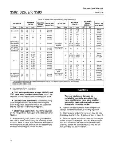
Table 10. Fisher 3582 and 3583 Mounting Information MAXIMUM TRAVEL
ACTUATOR Type
Size
mm
Inch
MOUNTING TRAVEL PIN HOLES POSITION(2) SET NO.(1)
513 & 513R
20 32
19 19
0.75 0.75
2 2
Normal Normal
656
30 40 60
51 89 102
2 3.5 4
4 4 4
Inverted Inverted Inverted
70
102
4
3
Inverted
70 87
102 102
4 4
2 1
Inverted Inverted
30 34 40 40
54 54 79 89
2.125 2.125 3.125 3.5
3 3 3 3
Normal Normal Normal Normal
46 46 47 47 60 70
79 105 79 105 105 105
3.125 4.125 3.125 4.125 4.125 4.125
2 2 2 1 4 2
Normal Normal Inverted Inverted Inverted Inverted
70 87
102 102
4 4
1 1
Normal Normal
657-4 Without Side-Mounted Handwheel 657-4 With Side-Mounted Handwheel
657-8
667-4 Without Side-Mounted Handwheel 1. 2. 3. 4.
Type
657 & 667 Without Side-Mounted Handwheel
657 & 667 With Side-Mounted Handwheel
MAXIMUM TRAVEL
Size
mm
Inch
30 34 40 45 45 50 60
19 19 38 19 51 51 51
0.75 1.125 1.5 0.75 2 2 2
70
51 2 52−76 2.0625-3 78−102 3.0625-4
MOUNTING HOLES SET NO.(1) 657 667
TRAVEL PIN POSITION(2)
3 3 2 1 1 1 1
4 2 3 4 1 2 2
Normal Normal Normal Inverted(3) Normal Normal Normal
2 3 3
1 2 1
Normal Normal Inverted(4)
80
76
3
2
2
Normal
87
51 52-76 78-102
2 2.0625-3 3.0625-4
2 2 3
2 2 1
Normal Normal Inverted(4)
100
102
4
4
4
Inverted
34 40 45 50 60 70 80
19 38 51 51 51 102 76
0.75 1.5 2 2 2 4 3
2 1 1 4 3 2 2
2 2 4 1 1 2 2
Normal Normal Normal Inverted(4) Inverted(4) Inverted Normal
2 2
2 1
Normal Inverted
87
76 3 78−102 3.0625-4
The indicated set number should be considered a reference point only, due to the variables related to making up the stem connection. Normal position is shown in figure 4. Travel pin position for 657 is normal. Travel pin position for 667 is normal.
4. Mount the 67CFR regulator: D 3582 valve positioners (except 3582NS) and 3583 valve stem position transmitters, mount the regulator on the integral boss on the bypass block. D 3582NS valve positioners, use the mounting plate with provision for separately mounting the 67CFR regulator. Separately mount the positioner and the regulator on the mounting plate. D 3582i valve positioners, mount the regulator on the integral boss that is part of the 582i converter housing. 5. As shown in figure 5, the mounting bracket has four sets of holes for mounting the assembly to the actuator. Refer to table 10 to determine which set of mounting holes to use, then attach the assembly to the lower mounting pad on the actuator.
12
ACTUATOR
CAUTION To avoid equipment damage, be certain the connector arm clears the valve positioner or valve stem position transmitter case as the actuator moves through its complete stroke. 6. Position the actuator to its mid-travel position using a handwheel or manual loading regulator. 7. Slip the round end of the travel pin (key 60) into the rotary shaft arm (key 2) slot as shown in figure 4. 8. Slide the square end of the travel pin into the pin holder and pin lock (keys 61 and 59). Place the pin lock and holder into the slot in the connector arm (key 48). Screw the cap nut (key 62) onto the pin lock (key 59), but do not tighten.