Fusion Reactor Design: Plasma Physics, Fuel Cycle System, Operation and Maintenance 1st Edition Takashi
Okazaki
Visit to download the full and correct content document: https://ebookmass.com/product/fusion-reactor-design-plasma-physics-fuel-cycle-syst em-operation-and-maintenance-1st-edition-takashi-okazaki/
FusionReactorDesign
FusionReactorDesign
PlasmaPhysics,FuelCycleSystem,Operationand Maintenance
TakashiOkazaki
Author
Dr.TakashiOkazaki
2660-29Mawatari
Hitachinaka-shi
312-0012Ibaraki
Japan
CoverDesign:Wiley
CoverImage:©dani3315/iStock/Getty Images
Allbookspublishedby WILEY-VCH arecarefully produced.Nevertheless,authors,editors,and publisherdonotwarranttheinformation containedinthesebooks,includingthisbook, tobefreeoferrors.Readersareadvisedtokeep inmindthatstatements,data,illustrations, proceduraldetailsorotheritemsmay inadvertentlybeinaccurate.
LibraryofCongressCardNo.: appliedfor
BritishLibraryCataloguing-in-PublicationData A cataloguerecordforthisbookisavailablefrom theBritishLibrary.
Bibliographicinformationpublishedbythe DeutscheNationalbibliothek TheDeutsche Nationalbibliothekliststhispublicationinthe DeutscheNationalbibliografie;detailed bibliographicdataareavailableontheInternet at <http://dnb.d-nb.de>
©2022WILEY-VCHGmbH,Boschstr.12, 69469Weinheim,Germany
Allrightsreserved(includingthoseof translationintootherlanguages).Nopartof thisbookmaybereproducedinanyform–by photoprinting,microfilm,oranyother means–nortransmittedortranslatedintoa machinelanguagewithoutwrittenpermission fromthepublishers.Registerednames, trademarks,etc.usedinthisbook,evenwhen notspecificallymarkedassuch,arenottobe consideredunprotectedbylaw.
PrintISBN: 978-3-527-41403-1
ePDFISBN: 978-3-527-83292-7
ePubISBN: 978-3-527-83294-1
oBookISBN: 978-3-527-83293-4
Typesetting Straive,Chennai,India PrintingandBinding
Printedonacid-freepaper
10987654321
v Contents Preface xxv 1CharacteristicsoftheFusionReactor 1 1.1TheFusionReactorasanEnergySource 1 1.1.1TrendsinWorldEnergyConsumption 1 1.1.2EnergyClassification 1 1.1.3NuclearFusionPowerGeneration 2 1.2NuclearFusionReaction 3 1.2.1NuclearReactionUsedintheFusionReactor 3 1.2.2CrossSectionoftheFusionReaction 4 1.2.3FusionReactionRate 5 1.3PlasmaConfinementConcept 7 1.3.1MagneticConfinement 7 1.3.1.1LinearSystem(Open-EndSystem) 7 1.3.1.2ToroidalSystem 9 1.3.2InertialConfinement 13 References 15 2BasisoftheFusionReactor 17 2.1PowerFlow 17 2.2FusionReactorStructure 19 2.3PowerGenerationConditionsoftheFusionReactor 20 2.3.1PowerFlowofthePowerPlant 20 2.3.2PlantEfficiency 21 2.3.3FuelSupplyScenario 22 2.4CorePlasmaConditions 22 2.4.1Break-EvenConditionandSelf-IgnitionCondition 22 2.4.2LawsonCriterion 22 2.4.3TypicalReactorConcepts 24 2.5RequirementsofPlasmaintheFusionReactor 24 2.5.1FusionTripleProduct 25 2.5.2 β Value 25 2.5.3CurrentDriveEfficiency 25
vi Contents 2.6OperationScenario 26 2.6.1PulseOperation 26 2.6.2Quasi-steady-stateOperation 27 2.6.3Steady-stateOperation 28 2.7StepwiseDevelopmentResearchoftheFusionReactor 28 2.7.1ExperimentalReactor 29 2.7.2PrototypeReactor 29 2.7.3DemonstrationReactor/CommercialReactor 29 References 29 3BasicsofPlasmaAnalysis 31 3.1BoltzmannEquation 31 3.2PlasmaAnalysis 32 3.2.1VelocityInformation 33 3.2.2NonlinearEffects 33 3.2.3ExternalElectromagneticField 33 3.2.4NumericalSimulation 33 3.2.5MainPlasmaTheories 33 3.3MagnetohydrodynamicEquation 35 3.3.1MacroscopicPhysicalQuantity 35 3.3.1.1MomentumFlowTensorP(r, t) 36 3.3.1.2PressureTensorp(r, t) 36 3.3.1.3EnergyDensity ��(r, t) 36 3.3.1.4InternalEnergyDensity U (r, t) 36 3.3.1.5EnergyFluxVectorQ(r, t) 36 3.3.2ParticleNumberConservationLaw(EquationofContinuity) 37 3.3.3MomentumConservationLaw 38 3.3.4EnergyConservationLaw 39 3.4KineticEquation 39 3.5LinearizedKineticAnalysis(OneDimension) 41 3.6LinearizedKineticAnalysis(ThreeDimensions) 43 3.7Quasi-LinearTheory 46 3.8TurbulenceTheory 49 3.8.1WeakTurbulenceTheory 49 3.8.1.1Wave–ParticleInteraction 51 3.8.1.2Wave–Wave(3Waves)Interaction 52 3.8.1.3NonlinearWave–ParticleInteraction 52 3.8.1.4Wave–Wave(4Waves)Interaction 52 3.8.2StrongTurbulenceTheory 53 3.9NeutronTransportAnalysis 53 3.9.1TransportEquation 53 3.9.2InteractionBetweenNeutronsandMaterials 54 References 55
Contents vii 4PlasmaEquilibriumandStability 57 4.1PlasmaEquilibrium 57 4.1.1PlasmaPressure 57 4.1.2EquilibriumEquation 59 4.1.3TokamakEquilibrium 61 4.1.4PlasmaCrossSection 63 4.2MHDStability 64 4.2.1EnergyPrinciple 64 4.2.1.1MHDEquation 64 4.2.1.2LinearizedIdealMHDEquation 66 4.2.1.3EnergyPrinciple 67 4.2.2EnergyIntegral 68 4.2.3MHDInstability 69 4.2.4MHDModeandResonantSurface 69 4.3PlasmaPositionalInstability 71 4.4KinkInstability 74 4.4.1Characteristics 74 4.4.2DispersionRelation 74 4.4.3StabilizationMethod 76 4.5InterchangeInstability 77 4.6BallooningInstability 78 4.6.1Characteristics 78 4.6.2EnergyIntegral 79 4.6.3StabilizationMethod 81 4.7ResistiveInstability 82 4.7.1TearingMode 83 4.7.1.1Characteristics 83 4.7.1.2BasicEquations 84 4.7.1.3MagneticIslandWidth 85 4.7.1.4MagneticIslandEvolutionEquation 86 4.7.1.5StabilizationMethod 88 4.7.2NeoclassicalTearingMode 88 4.7.2.1Characteristics 88 4.7.2.2DifferenceintheLogarithmicDerivativeDuetoBootstrapCurrent 89 4.7.2.3MagneticIslandEvolutionEquation 89 4.7.2.4StabilizationMethod 89 4.8DriftInstability 90 4.8.1DensityGradient 90 4.8.2DensityGradientandTemperatureGradient 90 4.8.3ResistiveDriftMode 92 4.8.4InfluenceofDriftWaveonPlasmaTransport 95 4.9ResistiveWallInstability 96 4.9.1Characteristics 96 4.9.2StabilizationMethod 97
viii Contents 4.10InstabilityDuetoHighEnergyParticles 98 4.10.1AlfvénEigenmode 98 4.10.1.1Characteristics 98 4.10.1.2DispersionRelation 99 4.10.1.3InstabilityConditionandStabilizationMethod 100 4.10.2FishboneOscillation 102 4.11SawtoothOscillation 102 4.12EdgeLocalizedMode 102 4.13LockedMode 103 4.14FutureChallenges 103 Appendix4A 103 Appendix4B 107 References 111 5PlasmaTransportandConfinement 113 5.1ConfinementTime 113 5.2PlasmaTransport 114 5.2.1DiffusionbyCollision 114 5.2.2DiffusionbyTurbulence 116 5.2.2.1BohmDiffusion 116 5.2.2.2Gyro-BohmDiffusion 118 5.2.2.3EnergyConfinement 119 5.3ScalingLawofEnergyConfinement 119 5.3.1ParameterDependenceofEnergyConfinementTime 119 5.3.2ScalingLaw 120 5.3.3L–HTransitionThresholdPower 122 5.3.4ImprovedConfinementMode 122 5.4EdgeLocalizedMode 124 5.4.1TypesofEdgeLocalizedMode 124 5.4.2EnergyReleasedbyELM 125 5.4.3MeasuresAgainstELM 127 5.5 β Limit 127 5.5.1PlasmaCurrentProfile 128 5.5.2PlasmaPressureProfile 128 5.5.3ShapeofPlasmaCrossSection 129 5.5.4NeoclassicalTearingMode 129 5.6DensityLimit 129 5.7ConfinementofHigh-EnergyParticles 129 5.8Disruption 130 5.8.1PlasmaBehaviorinDisruptionandCauseoftheOccurrence 131 5.8.1.1PlasmaBehavior 131 5.8.1.2CausesofDisruption 133 5.8.2EffectonEquipment 133 5.8.2.1ThermalLoad 133 5.8.2.2ElectromagneticForce 134
Contents ix 5.8.3CountermeasuresAgainstDisruption 135 5.9FutureChallenges 137 References 137 6PlasmaDesign 141 6.1ParticleandEnergyBalancesofPlasma(OneDimension) 141 6.1.1ThermalConductionLossPower 143 6.1.2ConvectionLossPower 143 6.1.3 α HeatingPower 143 6.1.4AdditionalHeatingPower 144 6.1.5Joule(Ohmic)HeatingPower 144 6.1.6Electron-IonEnergyTransfer 144 6.1.7RadiationLossPower 145 6.2ParticleandEnergyBalancesofPlasma(ZeroDimension) 145 6.2.1Zero-DimensionalParticleandEnergyBalances 145 6.2.2PlasmaTemperatureandDensityinSteady-StateOperation 146 6.3Burn-UpFraction 148 6.4PlasmaCircuit 150 6.5ReactorStructure 152 6.5.1RadialBuild 152 6.5.2MagneticFluxRequiredforOperation 153 6.5.3MagneticFluxtoBeSupplied 154 6.6FutureChallenges 155 References 156 7Blanket 157 7.1FunctionsRequiredfortheBlanket 157 7.2TritiumProduction 157 7.2.1NecessityofTritiumProduction 157 7.2.2TritiumBreedingRatio 159 7.2.3TritiumDoublingTime 159 7.2.4ImprovementofTritiumBreedingRatio 160 7.2.4.1 6 Li(n,T)α ReactionCrossSection 161 7.2.4.2 7 Li(n,n′ T)α ReactionCrossSection 161 7.2.4.3TritiumBreedingMaterial 161 7.2.4.4NeutronFlux 163 7.2.4.5BlanketCoverage 164 7.2.5RecoveryofTritium 165 7.3TakingOutofThermalEnergy 165 7.3.1EnergyMultiplicationFactoroftheBlanket 165 7.3.2PowerGenerationEfficiencyandCoolantTemperature 166 7.3.2.1TemperatureofBreederandMultiplierMaterials 166 7.3.2.2TemperatureoftheBlanketStructuralMaterial 167 7.3.2.3Coolant 167 7.3.3TemperatureProfile 168
x Contents 7.3.4PowerGenerationMethod 170 7.3.4.1PowerGenerationMethodsofFissionReactorandThermalPower Plant 171 7.3.4.2CharacteristicsofFusionPowerGeneration 172 7.3.4.3CombinationofCoolants 173 7.3.4.4FusionPowerGeneration 175 7.4RadiationShieldingFunction 175 7.4.1BlanketThickness 175 7.4.2LowRadioactivation 176 7.5Maintenance 176 7.5.1ExtensionofLife 176 7.5.1.1WearAmountofLithiumbyBurningofTritiumBreedingMaterial 177 7.5.1.2WearAmountofBerylliumbyBurningofNeutronMultiplier Material 178 7.5.1.3WearAmountofFirstWall 179 7.5.1.4NuclearDamageDuetoDisplacementDamage,HydrogenandHelium Productions,Swelling,etc. 179 7.5.1.5ChangeinThermalLifeofStructuralMaterialsDuetoCycleThermal Fatigue 179 7.5.2MaintenanceMethod 179 7.5.2.1WearAmountandReplacementFrequency 179 7.5.2.2RemoteMaintenanceMethod 180 7.6BlanketDesign 181 7.6.1BlanketClassification 181 7.6.2DesignConditions 181 7.6.3BlanketConcept 181 7.6.3.1BlanketConfiguration 181 7.6.3.2SizeofaBlanket 183 7.6.4DesignExample 185 7.7FutureChallenges 187 References 189 8Plasma-FacingComponents 191 8.1FunctionsRequiredforPlasma-FacingComponents 191 8.1.1RequiredFunctions 191 8.1.1.1ImpurityControl 191 8.1.1.2PlasmaParticleControl 191 8.1.1.3ThermalTreatmentofPlasmaThermalEnergy 192 8.1.2LimiterandDivertor 192 8.2DivertorCharacteristics(inSteadyState) 193 8.2.1BasicCharacteristicsofDivertorPlasma 193 8.2.2Two-PointModel 194 8.2.3AttachedStateandDetachedState 196 8.2.4Two-DimensionalDivertorAnalysisModel 197 8.2.5MeasuresforReducingParticleandThermalLoads 200
Contents xi 8.2.5.1ImpurityControl 200 8.2.5.2ParticleControl 200 8.2.5.3AverageHeatFluxtotheDivertorPlate 200 8.3DivertorCharacteristics(inNon-steadyState) 201 8.3.1ELM 201 8.3.2Disruption 202 8.3.2.1ThermalLoad 202 8.3.2.2ElectromagneticForce 203 8.4StructuresofLimiterandDivertor 203 8.4.1ShapeandTypeofLimiterandDivertor 203 8.4.1.1TrendsinImpurityControlResearch 203 8.4.1.2LimiterandPumpedLimiter 204 8.4.1.3Divertor 204 8.4.1.4ComparisonofPumpedLimiterandDivertor 205 8.4.2ComparisonofSingleNullDivertorandDoubleNullDivertor 206 8.4.3ShapeofDivertor 206 8.5DivertorDesign 208 8.5.1DesignConditionsandDesignItems 208 8.5.2MaterialSelection 210 8.5.3StructuralConcept 212 8.5.3.1HeatReceivingPlateStructure 212 8.5.3.2EddyCurrentSuppressionStructure 213 8.5.3.3ReductionofStressandStrain 213 8.5.3.4CoolingTube 213 8.5.4DesignExample 214 8.6FirstWall 217 8.6.1ParticleLoadandThermalLoad 217 8.6.2First-WallStructure 218 8.6.2.1OverallStructure 218 8.6.2.2ProtectionStructure 218 8.6.2.3FlowPathCrossSection 218 8.6.2.4AmountofWear 220 8.6.3DesignExample 220 8.7FutureChallenges 222 References 222 9CoilSystem 227 9.1FusionReactorCoils 227 9.1.1TypesofCoils 227 9.1.2NecessityofSuperconductingCoil 227 9.2BasicsofSuperconductingCoils 228 9.2.1CharacteristicsofSuperconductivity 228 9.2.2SuperconductingMaterials 228 9.2.3ManufacturingMethodsforSuperconductingWires 229 9.2.3.1NbTi 229
xii Contents 9.2.3.2Nb3 Sn 230 9.2.3.3Nb3 Al 230 9.2.3.4MgB2 231 9.2.3.5Bismuth-BasedOxide 231 9.2.3.6Yttrium-BasedOxide 231 9.2.4SuperconductingWires 231 9.2.4.1HysteresisLoss 231 9.2.4.2StabilizingMaterials(Stabilizers) 232 9.2.4.3Twist 232 9.2.4.4CoolingPerformance 232 9.2.5ThermalLoadandCoolingMethods 232 9.2.5.1ThermalLoad 232 9.2.5.2CoolingMethods 233 9.2.6ConductorStructure 234 9.2.6.1CriticalCurrent 235 9.2.6.2LimitedCurrent 236 9.2.6.3StabilityMargin 236 9.2.6.4CoilAverageCurrentDensity 237 9.2.6.5ConductorDesign 237 9.2.7CoilStructure 237 9.2.7.1Structure 237 9.2.7.2StructuralMaterial 238 9.3BasicsofToroidalMagneticFieldCoil 238 9.3.1FunctionsforToroidalMagneticFieldCoil 239 9.3.2CoilCurrentandNumberofCoils 239 9.3.2.1CoilCurrent 239 9.3.2.2NumberofCoils 239 9.3.2.3StoredEnergy 241 9.3.3ElectromagneticForceGeneratedinCoil 241 9.3.3.1ExtensionalForce 241 9.3.3.2CenteringForce 242 9.3.3.3OverturningForce 242 9.3.4CoilShape 242 9.3.4.1Shape 242 9.3.4.2Three-ArcApproximation 243 9.3.5MaximumMagneticField 245 9.4DesignofToroidalMagneticFieldCoil 245 9.4.1ConductorDesign 246 9.4.1.1SelectionofSuperconductingMaterial 246 9.4.1.2CoolingMethod 246 9.4.2DesignofCoilStructure 246 9.4.2.1CoilStructure 246 9.4.2.2SelectionofStructuralMaterials 246 9.4.3SupportStructure 247 9.4.3.1SupportStructurefortheCenteringForce 247
Contents xiii 9.4.3.2SupportStructurefortheOverturningForce 249 9.4.3.3SupportStructureofOwnWeight 249 9.4.4DesignExample 249 9.5BasicsofPoloidalMagneticFieldCoil 254 9.5.1FunctionsofPoloidalMagneticFieldCoil 254 9.5.2WaveformPatternofCoilCurrentforControlofPlasmaPositionand Shape 255 9.5.3PositionofPoloidalMagneticFieldCoil 256 9.6CurrentControlofPoloidalMagneticFieldCoil 256 9.6.1MagneticFieldConfigurationtoDeterminethePlasmaShape 256 9.6.2ControlofPlasmaPositionandShape 257 9.6.3GenerationTypesofPoloidalMagneticField 258 9.6.4Function-SpecificCoilSystem 259 9.6.5HybridCoilSystem 260 9.6.5.1NumberofPFCoils 260 9.6.5.2DeterminingthePFCoilPosition 260 9.6.5.3DeterminingthePFCoilCurrent 260 9.7DesignofPoloidalMagneticFieldCoil 263 9.7.1ConductorDesign 263 9.7.1.1SelectionofSuperconductingMaterial 263 9.7.1.2CoolingMethod 263 9.7.2DesignofCoilStructure 263 9.7.2.1CoilStructure 263 9.7.2.2SelectionofStructuralMaterials 263 9.7.2.3SupportStructure 264 9.7.3DesignExample 264 9.8BasicsofCentralSolenoidCoil 265 9.8.1FunctionsofCentralSolenoidCoil 265 9.8.2MagneticFieldofCentralSolenoidCoil 266 9.8.3SuppliedMagneticFlux 266 9.9DesignofCentralSolenoidCoil 267 9.9.1ConductorDesign 267 9.9.1.1SelectionofSuperconductingMaterial 267 9.9.1.2CoolingMethod 268 9.9.2DesignofCoilStructure 268 9.9.2.1CoilStructure 268 9.9.2.2SelectionofStructuralMaterials 268 9.9.2.3SupportStructure 268 9.9.3DesignExample 268 9.10FutureChallenges 270 References 271 10PlasmaHeatingandCurrentDrive 273 10.1NecessityofPlasmaHeatingandCurrentDrive 273 10.1.1PlasmaHeating 273
xiv Contents 10.1.2CurrentDrive 274 10.2BasicsofNBIHeating 275 10.2.1IonizationofNeutralParticleBeam 275 10.2.2TrajectoryofIonBeam 276 10.2.2.1DirectionofInjection 276 10.2.2.2TrappedCondition 277 10.2.2.3TrajectoryofBeamIon 278 10.2.3PlasmaHeatingbyEnergyRelaxation 279 10.3BasicsofNBICurrentDrive 281 10.3.1DrivenCurrent 281 10.3.2CurrentDriveEfficiency 282 10.3.3ShineThroughRate 284 10.3.4CurrentDriveEfficiencyObtainedbyExperiments 284 10.4BootstrapCurrent 285 10.4.1TrappedElectronOrbitandBootstrapCurrent 285 10.4.2RatiooftheBootstrapCurrent 286 10.5BasicsofRadioFrequencyHeating 287 10.5.1DispersionRelation 287 10.5.2DispersionRelationofColdPlasma 288 10.5.3DispersionRelationofHotPlasma 289 10.5.4DispersionRelationofPlasmawithMaxwellDistribution 290 10.5.5CharacteristicsofRFWaves 291 10.5.5.1PhaseVelocityandGroupVelocity 291 10.5.5.2CutoffandResonance 292 10.5.5.3Polarization 292 10.5.6PropagationCharacteristicsofRFWaves 293 10.5.6.1WhentheWaveNumberVectorisParalleltotheMagneticField 294 10.5.6.2WhentheWaveNumberVectorisPerpendiculartotheMagnetic Field 296 10.5.7PrinciplesofPlasmaHeating 297 10.5.7.1LandauDamping 298 10.5.7.2TransitTimeDamping 298 10.5.7.3CyclotronDamping 299 10.5.7.4AbsorptionPower 299 10.5.8PropagationinNonuniformPlasma 300 10.6VariousRFWaves 301 10.6.1AlfvénWave 301 10.6.2IonCyclotronWave 303 10.6.2.1Right-handedCutOffandLeft-handedCutOff 304 10.6.2.2DensityatWhichtheWavecanPropagate 305 10.6.2.3CharacteristicsoftheSlowWave 305 10.6.2.4CharacteristicsoftheFastWave 305 10.6.3LowerHybridWave 307 10.6.3.1ResonanceandCutOff 307 10.6.3.2AccessibilityCondition 309
Contents xv 10.6.4ElectronCyclotronWave 310 10.6.4.1AbsorptionPower 311 10.6.4.2ResonanceandCutOff 311 10.6.4.3PropagationPath 311 10.7BasicsofRFCurrentDrive 313 10.7.1GeneralTheoryofRFCurrentDrive 313 10.7.1.1VariousNoninductiveCurrentDriveMethods 313 10.7.1.2NormalizedCurrentDriveEfficiency 314 10.7.1.3CurrentDriveUsingMomentumoftheWave 315 10.7.1.4CurrentDriveUsingAnisotropyoftheVelocitySpace 316 10.7.1.5CurrentDriveEfficiency 316 10.7.2CurrentDriveUsingMomentumoftheWave 316 10.7.2.1Fokker–PlanckEquationinOneandTwoDimensions 316 10.7.2.2DrivenCurrentDensityandCurrentDrivePowerDensity 318 10.7.2.3LHCD(One-DimensionalAnalysis) 318 10.7.2.4DCElectricField 318 10.7.2.5LHCD(Two-DimensionalAnalysis) 320 10.7.3CurrentDrivewithAnisotropyoftheVelocitySpace 321 10.7.3.1Two-DimensionalFokker–PlanckEquation 321 10.7.3.2RelativisticEffect 323 10.7.3.3TrappedEffect 324 10.7.4CurrentDriveEfficiencyObtainedbyExperiments 327 10.7.4.1FastWaveCurrentDrive(FWCD) 327 10.7.4.2LHCD 328 10.7.4.3ECCD 329 10.8NBISystemDesign 330 10.8.1DesignRequirements 330 10.8.1.1RequiredFunctions 330 10.8.1.2DesignRequirements 330 10.8.1.3SystemEfficiency 330 10.8.2SystemConfiguration 331 10.8.2.1Positive-ionNBI 331 10.8.2.2Negative-ionNBI 332 10.8.3Negative-ionSource 332 10.8.3.1Negative-ionGenerator 332 10.8.3.2Accelerator 334 10.8.4BeamTransportSystem 334 10.8.4.1BeamProfileControlUnit 334 10.8.4.2NeutralizationCell(Neutralizer) 334 10.8.4.3ResidualIonBendingMagnetandResidualIonDump 335 10.8.4.4VacuumExhaustSystem 335 10.8.5DesignExample 335 10.8.6FutureChallenges 336 10.9SystemDesignoftheIonCyclotronWave 337 10.9.1DesignRequirements 337
xvi Contents 10.9.1.1RequiredFunctions 337 10.9.1.2ICRFExcitationMethod 338 10.9.1.3SystemEfficiency 338 10.9.2SystemConfiguration 339 10.9.2.1RFSource 339 10.9.2.2TransmissionSystem 339 10.9.2.3InjectionSystem 340 10.9.3DesignExample 340 10.9.4FutureChallenges 342 10.10SystemDesignoftheLowerHybridWave 342 10.10.1DesignRequirements 342 10.10.1.1RequiredFunctions 342 10.10.1.2LHWExcitationMethod 343 10.10.1.3PlasmaDensityinFrontoftheLauncher 344 10.10.1.4SystemEfficiency 344 10.10.2SystemConfiguration 344 10.10.2.1RFSource 345 10.10.2.2TransmissionSystem 345 10.10.2.3InjectionSystem(Launcher) 346 10.10.2.4PhaseShifter 347 10.10.3DesignExample 348 10.10.4FutureChallenges 350 10.11SystemDesignoftheElectronCyclotronWave 350 10.11.1DesignRequirements 350 10.11.1.1RequiredFunctions 350 10.11.1.2ECWExcitationMethod 351 10.11.1.3SystemEfficiency 352 10.11.2SystemConfiguration 353 10.11.2.1VariousSystemConfigurations 353 10.11.2.2RFSource 354 10.11.2.3TransmissionSystem 355 10.11.2.4InjectionSystem(Launcher) 355 10.11.3DesignExample 356 10.11.4FutureChallenges 357 Appendix10A 358 Appendix10B 363 Appendix10C 369 Appendix10D 373 Appendix10E 377 References 380 11VacuumVessel 385 11.1FunctionsRequiredforVacuumVessel 385 11.2HoldingUltra-HighVacuumandHigh-TemperatureBaking 385 11.2.1DegreeofVacuumintheVacuumVessel 385
Contents xvii 11.2.2HoldingtheUltra-highVacuum 386 11.2.3High-TemperatureBaking 387 11.3EnsuringElectricalResistance,PlasmaPositionControl,andToroidal FieldRipple 387 11.3.1ElectricalResistanceoftheVacuumVessel 387 11.3.2EnsuringElectricalResistance 390 11.3.3PlasmaPositionControl 391 11.3.4ToroidalFieldRipple 391 11.4SupportingtheElectromagneticForceandIn-VesselEquipment 392 11.4.1SupportingtheElectromagneticForce 392 11.4.2SupportingtheVacuumVessel 392 11.5CoolingPerformance,RadiationShielding,Confinement,Assembly,and Maintenance 394 11.5.1CoolingPerformance 394 11.5.2RadiationShielding 394 11.5.3ConfinementofRadioactiveMaterial 394 11.5.4AssemblyandMaintenance 395 11.5.4.1Assembly 395 11.5.4.2Maintenance 395 11.6DesignofVacuumVessel 396 11.6.1StructuralStandard 396 11.6.2DesignItems 396 11.6.3DesignExample 398 11.6.3.1HoldingUltra-highVacuum 398 11.6.3.2SurfaceCleaningSystem 399 11.6.3.3EnsuringElectricalResistance,PlasmaPositionControl,andToroidal FieldRipple 400 11.6.3.4SupportingElectromagneticForceandIn-vesselEquipment 400 11.6.3.5CoolingofVacuumVessel,RadiationShielding,andConfinement 400 11.6.3.6Assembly 401 11.6.3.7Maintenance 401 11.7FutureChallenges 402 References 402 12FuelCycleSystem 405 12.1FunctionsRequiredfortheFuelCycleSystem 405 12.2ConfigurationoftheFuelCycleSystem 405 12.3FuelingSystem 407 12.3.1FuelingMethod 407 12.3.2FuelingAmount 407 12.4GasExhaustSystem 408 12.4.1ExhaustGasesbySource 408 12.4.2PlasmaVacuumExhaustSystem 408 12.4.2.1TypesofVacuumExhaustPump 408 12.4.2.2Configuration 409
xviii Contents 12.4.2.3InitialUltimatePressure 409 12.4.2.4HeliumPumpingSpeed 411 12.4.2.5CryopanelArea 412 12.4.2.6HeliumAccumulationontheCryopanel 412 12.4.2.7ExhaustTime 413 12.5FuelClean-upSystem 414 12.5.1KindsofRecoveredGasandAmountofExhaustGas 414 12.5.2ConfigurationoftheFuelClean-UpSystem 414 12.6HydrogenIsotopeSeparationSystem 416 12.7AtmosphereDetritiationSystem 418 12.8WaterDetritiationSystem 418 12.9FuelStorageSystem 419 12.10MaterialAccountancyofTritium 420 12.11DesignExample 420 12.11.1FuelCycleSystem 420 12.11.2FuelingSystem 421 12.11.3TokamakExhaustProcessingSystem 422 12.11.4HydrogenIsotopeSeparationSystem 422 12.11.5AtmosphereDetritiationSystem 422 12.11.6WaterDetritiationSystem 423 12.11.7FuelStorageSystem 423 12.12FutureChallenges 423 References 424 13Cryostat 425 13.1FunctionsofCryostat 425 13.2CryostatStructure 425 13.3ThermalShield 425 13.3.1DesignRequirements 427 13.3.2Structure 428 13.4DesignExample 429 13.5FutureChallenges 432 References 433 14NuclearDesign 435 14.1ItemsRequiredforNuclearDesign 435 14.2RadiationShielding 437 14.2.1MainShield 437 14.2.1.1EquipmentShieldingandBiologicalShielding 437 14.2.1.2InstallationPositionofShields 438 14.2.1.3ActivationofAirandCoolingWater 439 14.2.2EvaluationMethodofRadiationShielding 440 14.2.2.1IntensityofNeutronSource 440 14.2.2.2NuclearData 440
Contents xix 14.2.2.3AnalysisCode 440 14.2.2.4AnalysisProcedure 440 14.3DoseRate 441 14.4NuclearHeating 441 14.5RadiationDamage 442 14.5.1SurfaceDamage 442 14.5.1.1Sputtering 442 14.5.1.2Blistering 444 14.5.2BulkDamage 444 14.5.2.1DisplacementDamage 444 14.5.2.2DamageDuetoNuclearTransmutation 445 14.6RadioactiveWaste 447 14.7DesignExample 448 14.7.1NeutronFlux 449 14.7.2dpaDistribution 449 14.7.3HeliumProduction 450 14.7.4DoseRate 450 14.7.5DoseRatebySkyshine 452 14.7.6NuclearHeatingandSoon 452 14.8FutureChallenges 453 References 453 15OperationandMaintenance 457 15.1FunctionsRequiredforOperationandMaintenance 457 15.1.1HighPlantAvailability 457 15.1.2MaintenanceMethodConsistentwiththeReactorStructure 457 15.1.3RemoteMaintenancewithHighEfficiencyandHighReliability 458 15.2OperationPeriod 458 15.3EquipmenttobeInspectedandMaintained 459 15.4FrequencyofMaintenance 461 15.5RemoteMaintenanceMethods 461 15.6ProcessofRemoteMaintenance 463 15.7In-VesselTransportSystem 465 15.8DesignExample 466 15.8.1FrequencyofMaintenanceandMaintenancePeriod 466 15.8.2In-VesselTransportSystem 466 15.8.2.1MaintenanceofBlanketModule 466 15.8.2.2MaintenanceofDivertor 467 15.8.3Ex-VesselTransportSystem 468 15.8.4PipingCutting/WeldingTool 469 15.8.5FailureofMaintenanceDevice 469 15.8.6HotCellBuilding 469 15.9FutureChallenges 470 References 471
xx Contents 16CoolingSystem 473 16.1FunctionsofCoolingSystem 473 16.2ConfigurationofCoolingSystem 473 16.2.1OperationMode 473 16.2.2CoolingMethod 474 16.2.3HeatReservoir 474 16.3CoolingPerformance 476 16.4DesignExample 478 16.4.1ConfigurationofCoolingSystem 478 16.4.1.1TokamakCoolingWaterSystem 478 16.4.1.2ComponentCoolingWaterSystem 479 16.4.1.3ChilledWaterSystem 480 16.4.1.4HeatRejectionSystem 480 16.4.2DecayHeatRemovalinEmergency 480 16.4.2.1EmergencyPowerSupply 480 16.4.2.2NaturalCirculationMode 480 16.5FutureChallenges 480 References 481 17PowerSupplySystem 483 17.1FunctionsRequiredforthePowerSupplySystem 483 17.2CharacteristicsofthePowerSupplySystem 483 17.2.1PowerSupplyCapacity 483 17.2.2EquipmentandFacilitiestoWhichPowerIsSupplied 484 17.2.3TechnologiestoReduceCoilPowerSupplyCapacity 485 17.2.3.1HybridCoilSystem 485 17.2.3.2Superconductivity 485 17.2.3.3Steady-stateOperation 486 17.2.4ConfigurationofPowerSupply 488 17.3PowerSupplyforToroidalMagneticFieldCoil 489 17.3.1Self-inductance 489 17.3.2PowerSupplyVoltage 490 17.3.3StoredEnergyandCoilProtection 491 17.3.4ProtectionResistor 491 17.4PowerSupplyforPoloidalMagneticFieldCoil 492 17.4.1Inductance 492 17.4.1.1MutualInductance 492 17.4.1.2Self-inductanceofPFCoil 492 17.4.1.3Self-inductanceofCSCoil 493 17.4.2PowerSupplyVoltage 494 17.4.3PowerSupplyCapacity 494 17.4.4StoredEnergy 495 17.4.5CoilProtection 495 17.4.5.1AttheTimeofQuench 495
Contents xxi 17.4.5.2AttheTimeofPlasmaDisruption 495 17.5DesignExample 495 17.5.1CoilPowerSupply 496 17.5.2PowerSupplyofPlasmaHeatingandCurrentDriveSystem (H&CD) 497 17.6FutureChallenges 498 References 498 18OperationControlandDiagnosticSystems 501 18.1FunctionsofOperationControlandDiagnosticSystems 501 18.2BasicsofControl 502 18.2.1ControlMethod 502 18.2.2TransferFunction 503 18.2.3TransientResponseofaSystem 504 18.2.4FeedbackControl 504 18.2.5PIDController 505 18.2.5.1IdealPIDController 505 18.2.5.2PracticalNoninterference-TypePIDController 505 18.3OperationControlSystem 507 18.3.1CentralControlSystem 507 18.3.2PlasmaControl 507 18.3.2.1ControlofFusionPower 508 18.3.2.2MHDControl 509 18.3.2.3DisruptionControl 509 18.4DiagnosticSystems 511 18.4.1PassiveandActiveMeasurements 511 18.4.2ProbeMeasurement 512 18.4.2.1ElectrostaticProbe 512 18.4.2.2MagneticProbe,MagneticLoop,andRogowskiCoil 513 18.4.2.3DiamagneticCoil 513 18.4.3ElectromagneticWaveMeasurement 514 18.4.3.1PassiveElectromagneticWaveMeasurement 514 18.4.3.2ActiveElectromagneticWaveMeasurement 518 18.4.4ParticleMeasurement 522 18.4.4.1PassiveParticleMeasurement 522 18.4.4.2ActiveParticleMeasurement 528 18.5DesignExample 529 18.5.1OperationControlSystem 529 18.5.1.1PlantControlSystem 530 18.5.1.2InterlockLevel 530 18.5.1.3PlasmaOperation 531 18.5.2DiagnosticSystem 533 18.6FutureChallenges 535 References 536
xxii Contents 19Safety 539 19.1RequirementsforSafety 539 19.2RadioactiveMaterials 540 19.2.1Radioactivity 540 19.2.2ExposureDose 541 19.2.3AbsorbedDose 541 19.2.4DoseEquivalent/EffectiveDoseEquivalent 541 19.2.5EquivalentDose/EffectiveDose 542 19.2.6CommittedEffectiveDose 543 19.2.7TritiumConcentrationLimit 544 19.2.8BiologicalHazardPotential 544 19.3HowtoEnsureSafety 545 19.3.1SafetyFeatures 545 19.3.2GoaloftheSafety 546 19.3.2.1InNormalTime 546 19.3.2.2InEmergency 547 19.3.3BasicConceptofEnsuringtheSafety 547 19.3.3.1BasicConcept 547 19.3.3.2ImplementationofEnsuringSafety 548 19.3.4BasicConceptoftheSafetyDesign 548 19.3.5EvaluationoftheSafetyDesign 550 19.3.6WasteDisposal 550 19.4DesignExample 551 19.4.1DoseLimit 551 19.4.2BasicConceptofEnsuringtheSafety 552 19.4.3ImplementationofEnsuringtheSafety 552 19.4.3.1ReductionofRadioactiveMaterials 552 19.4.3.2ConfinementBarrierofRadioactiveMaterials 552 19.4.3.3EnergyThatDamagestheConfinementBarriers 553 19.4.3.4ZoningManagement 555 19.4.4SafetyDesign 555 19.4.5EventAnalysis 556 19.4.5.1EventsforAnalysis 556 19.4.5.2SafetyAnalysisCode 558 19.5FutureChallenges 558 References 560 20AnalysisCode 563 20.1HowtoDesign 563 20.1.1DesignFlow 563 20.1.2FlowofReactorDesign 563 20.1.2.1RequirementsasPowerReactor 564 20.1.2.2ConstructionofReactorConcept 564 20.1.2.3ClarificationofConstraints 565 20.1.2.4PlasmaDesign 565 20.1.2.5DesignofReactorStructure 566 20.1.2.6PlantDesign,Safety,andEconomicEvaluations 566
Contents xxiii 20.2VariousTypesofAnalysisCodes 566 20.2.1PlasmaAnalysisCode 566 20.2.2EquipmentAnalysis/DesignCode 567 20.2.3SafetyAnalysisCode 567 20.2.4DetailedAnalysisCode 567 20.3ReactorDesignSystemCode 567 20.3.1RoleoftheCode 567 20.3.2VariousSystemCodes 568 20.4SystemCodeforReactorConceptualDesign 570 20.4.1PowerBalance(EnergyBalanceperUnitTime) 570 20.4.2RadialBuild 571 20.4.3Volt-Second 572 20.4.4ShapeofTFCoil 573 20.4.5ElectromagneticForceActingontheTFCoil 573 20.4.5.1TensileStressDuetoVerticalForce 574 20.4.5.2BendingStressDuetoCenteringForce 575 20.4.5.3BendingStressDuetoOverturningForce 575 20.4.6BuckingCylinder 575 20.4.7RadiationShield 577 20.4.8VerticalBuild 577 20.4.9PowerSupplyCapacity 578 20.4.9.1TFCoil 578 20.4.9.2PFCoil 578 20.5SystemCodesforEconomicEvaluation 579 20.5.1CostofElectricity 579 20.5.2InitialCapitalizedInvestment 580 20.5.3DirectCostofConstruction 580 20.5.4AnnualCostofComponentReplacementatSpecificIntervals 581 20.5.5AnnualCostofOperationandMaintenance 581 20.5.6AnnualFuelCostandAnnualCostofWasteDisposaland Decommissioning 581 20.6SystemCodesforPlasmaDynamicsEvaluation 582 20.6.1ParticleBalanceandEnergyBalance 582 20.6.1.1ParticleBalanceEquation 582 20.6.1.2EnergyBalanceEquations 583 20.6.2 β Limit 584 20.6.3DensityLimit 584 20.6.4ThermalLoadonPlasma-FacingWall 585 20.6.5DistributionofNuclearHeatingRate 586 20.6.6ImpurityContaminationModelinPlasma 586 20.6.7HeatTransferModelofReactorStructure 587 20.6.8AnalysisExample 588 20.7FutureChallenges 590 References 590 Index 593
Preface
Manybooksonplasmaphysicsandfusionreactorengineeringhavebeen published–manypopularbooksrangingfrombasictospecializedonesforgraduate studentsandresearchers.Fusionresearchiscurrentlyintheconstructionstageof theexperimentalreactorandhasenteredanewstageofstudyingaprototype reactor.Reactordesignresearchisbecomingmoreimportant.However,there seemstobefewbooksonfusionreactordesign.Ithoughtthatasystematicand easy-to-understandintroductorybookonthedesignoffusionreactorsisneeded. Therefore,Idecidedtoputtogethermyexperienceindevelopmentresearch includingplasmaheatingandcurrentdrive,blanket,divertor,andsafetyintoan introductorybookonfusionreactordesign.
Afusionreactorconsistsofmanyinterrelatedequipmentpieces,soitisimportant toproceedwiththedevelopmentbasedontheunderstandingoftherelationships betweenthosepieces. FusionReactorDesign,whichexplainstheunderlyingrelations,hasbeenwrittenforuniversityandgraduatestudentswhoaregoingtostudy plasmaphysicsandfusionreactor.Forresearchersandengineersinthisfield,I wouldbegreatlyhappyifthisbookwouldserveasacatalysttoproceedtofurther researchanddevelopmentofadvancedtechnologiesinthisfield.Thisbookiscenteredaroundatokamakfusionreactor.Butitwouldbeanunexpectedjoyifitcould serveasareferenceforotherconfinementfusionreactordesigns.
Inapaper,todescribethedevelopmentofmathematicalformulasconcisely, ittakestimetoreaditandderivetheformulas.Inthisbook,Ihavetriedtoshowthe derivationofformulasinasmuchdetailaspossiblesothatthedevelopmentofthe formulascanbefollowedsmoothly.Also,tomakephysicalandstructuralimages easiertounderstand,Ihavetriedtouseasmanyfiguresaspossible.Andnumerical calculationsareshownasexamplestogetconcreteimages.
AnoverviewoffusionreactorsisgiveninChapters1and2.Chapters3–5outline theplasmaphysicsnecessaryforfusionreactors:Chapter3describesthebasics ofplasmaanalysis,Chapter4describesplasmaequilibriumandstability,and Chapter5describesplasmatransportandconfinement.Chapter6describesthe plasmadesign.InChapters7–18,eachequipmentpieceofthefusionreactorhas beenexplained,whichincludesblanket,divertor,superconductingcoil,plasma heatingandcurrentdrivesystem,vacuumvessel,fuelcyclesystem,operationand
xxv
maintenance,etc.Eachchapterdescribesthefunctionsrequiredforequipment,the factorstobeconsideredforachievingthosefunctions,theanalysismethodforevaluatingthefactors,requiredtechnology,designexamples,etc.Chapter19describes safetyandChapter20describesanalysiscodesnecessaryforreactordesign.
Thebookdiscussesthedevelopmentsthathavebeenevolvinginthefield,andalso therearesomecasesthatrequirephysicalclarificationandtechnologydevelopment. FromChapter4onward,suchcasesarelistedasfuturechallenges.Astheplasma analysisdiscussedinChapter3isappliedinthesechapters,futurechallengesof plasmaanalysisareshownthere.
Needlesstosay,itisimportanttomakeequipmentassimpleaspossibleandto designreactorsmostcost-efficientlyaspossiblefromtheoutsetofdevelopment.A fusionreactorisahugeandcomplicateddevice,anditisalsoacombinationofparts ofvarioussizes,soitisimportanttoconstructeachpartcarefully.Ihope Fusion ReactorDesign willhelpacceleratethefusionreactordesign.
Inwritingthisbook,Ireferredtomanybooksandliterature.Thisbookisbased onabookpublishedinJapaneseinJanuary2019withmodifications.Thebook is“KakuyugoRosekkeiNyumon”,MaruzenPlanet,MaruzenPublishingCo., Ltd.(Englishtranslation:“Introductiontofusionreactordesign”).Therefore, someJapanesearticlesarereferredtointhebook,soIhavetoapologizeforthe inconvenience.Ifthereareinadequateexplanations,errors,misunderstandings, etc.inthebook,Iwouldgreatlyappreciatereaders’feedback.
Booksandliteraturearelistedinthereferencesection.Booksandliteraturethat werereferredtowhendrawingthefiguresarecitedinthetext.Figuresreprinted frombooksandliteraturearepublishedwiththepermissionofauthorsand/or publishers.Throughthisbook,Ihavebeenabletointroducethoseexcellent achievementssofarinthefield.Iwouldliketoexpressmygratitudetothe concernedpeopleandrelatedorganizations.
ThepublicationhasbeengreatlysupportedbyDr.MartinPreuss,Ms.Daniela Bez,Ms.AneettaAntony,Mr.RanjithKumarNatarajan,Ms.ClaudiaNussbeck, Ms.BhavaniGaneshKumarandDr.GudrunWalteratWiley-VCH.Iwouldliketo expressmydeepestappreciationfortheirsupport.
July2021
xxvi Preface
TakashiOkazaki
CharacteristicsoftheFusionReactor
Manykindsofnuclearfusionreactionsandplasmaconfinementconceptscanbe consideredinfusionreactors.Thischaptershowsthecharacteristicsofthefusion reactor.
1.1TheFusionReactorasanEnergySource
1.1.1TrendsinWorldEnergyConsumption
Energyisnecessaryforhumankindtoliveandwork.Humanbeingshaveestablishedacivilizedsocietybydevelopingandutilizingenergysources.Figure1.1-1 showsthetransitionofworldenergyconsumptionbyfuel.Theworldenergy consumptionincreasesasthepopulationincreasesandtheeconomygrows;these areexpectedtofurtherincreaseinthefuture.Meanwhile,withtheincreaseinthe useoffossilfuelssuchascoal,oil,andnaturalgas,carbondioxideemissionshave greatlyincreased,causingenvironmentalproblemssuchasairpollutionandglobal warming.Forthefuturesurvivalandgrowthofhumanbeings,itisimportant thattheincreaseinenergyconsumptionandcountermeasurestoenvironmental problemsarecompatible.
1.1.2EnergyClassification
Energytakenfromnatureiscalledprimaryenergy,andenergyconvertedintoaform thatmakesprimaryenergyeasytouseiscalledsecondaryenergy.Table1.1-1shows theclassificationofenergy.
Primaryenergyincludesfossilenergyfromfossilfuels(coal,oil,naturalgas,shale oil,shalegas,methanehydrate,etc.),nuclearfissionenergyfromnon-fossilfuels, hydroelectricpowerenergy,andrenewableenergy(hydroelectricpower,solarlight, windpower,geothermalpower,solarheat,heatexistinginnaturesuchasatmosphericheat,biomass,etc.).Hydroelectricpower,aformofrenewableenergy,is particularlytargetedatthesmallandmediumscale.Secondaryenergyincludeselectricitygenerated,oilproducts,gasproducts,heat,etc.Secondaryenergyisdelivered andconsumedasfinalenergy.Finalenergycanbecategorizedaselectricpowerand fuel.Electricpower,asfinalenergy,isdiscussedhere.
FusionReactorDesign:PlasmaPhysics,FuelCycleSystem,OperationandMaintenance, FirstEdition.TakashiOkazaki.
©2022WILEY-VCHGmbH.Published2022byWILEY-VCHGmbH.
1 1
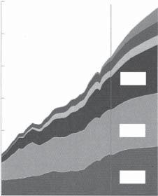
Figure1.1-1 Transitionofworld energyconsumptionbyfuel (Gtoe:gigatoe;toe:tonneofoil equivalent).Source:Ref.[1]. ©2015BPp.l.c.
Althoughthermalpowerthatcombustsfossilfuelscanbestablysuppliedona largescale,alargeamountofcarbondioxideisgeneratedduringthepowergenerationprocess.Thedevelopmentofprocessestocontrolthiscarbondioxideemission isongoing.Continuousconsumptionoffossilfuelswillresultindepletionofthe resourceinthefuture.Furthereffortsareneededtoextendminableyears.
Nuclearfissionpowercanbegeneratedandsuppliedstablyonalargescale.The fuelsupplycapacityiscomparabletothatoffossilfuels,andcarbondioxideemissionisminimal.Inaddition,socialacceptabilityofissuessuchassafety,disposalof radioactivewaste,managementofplutonium,etc.isimportant.
Hydroelectricpowergeneration(largescale)haslowcarbondioxideemission, butthereisageographicalrestrictionandlessroomfordevelopment.Renewable energyalsohaslowcarbondioxideemission,butitisimportanttomitigatethe effectsofclimateandsunshinehours.Therefore,consideringthecharacteristics oftheseenergies,itisimportanttomakeaproperlycombinedpowersupply configuration(energymix).
1.1.3NuclearFusionPowerGeneration
Thenuclearfusionreactorisroughlycategorizedbythetypeoffusionreactionto beused,namely,thefirst-generationDTreactor,thesecond-generationDDreactor,andthethird-generationp11 B(proton-boron)reactorandD3 Hereactor.Inthe first-generationreactor,deuterium(D)andtritium(T)areusedasfuels.Deuterium isanabundantandalmostinexhaustibleresourceavailableinseawater.Tritium israreinnature,andtherefore,itneedstobegeneratedbythereactionbetween lithiumandneutronsgeneratedfromthefusionreaction.Lithiumcanberecovered fromseawaterbesidelithiummines.Therefore,itcanbesaidthatthenuclearfusion reactorhasabundantresourcesasafundamentalalternativeenergysource.
Also,nuclearfusionpowergenerationhasnocarbondioxideemissions.Inthe caseofaDTreactor,tritium,whichisaradioactivematerial,isused.Sinceneutrons aregeneratedinthereaction,thereactorstructuralmaterialisactivatedandradioactivewasteisrequiredtobedisposed.Theradioactivewastegeneratedisalllowlevel.
2 1CharacteristicsoftheFusionReactor Oil Coal Gas World energy consumption by fuel ( Gtoe ) Renewable Hydroelectric Nuclear fission Year 1965 0 3 6 9 12 15 18 20002035
Table1.1-1
Classificationofenergy.
PrimaryenergySecondaryenergyFinalenergy
FossilenergyCoalThermalpower generation Electricpower Oil
Naturalgas
NuclearfissionenergyNuclearfissionpower generation
HydroelectricpowerenergyHydroelectricpower generation(largescale)
RenewableenergyHydroelectric power
Hydroelectricpower generation (small/mediumscale)
SolarlightPhotovoltaicpower generation
WindpowerWindpower generation
FossilenergyCoalCoalfuelFuel
OilOilfuel
NaturalgasGasfuel
RenewableenergySolarheatHeat,steam
Biomass
Geothermal
Theissueofactivationisfurtherreducedbecauseneutronenergyproducedinthe secondgenerationissmallerthaninthefirstandnoneutronisgeneratedinthethird (seeSection1.2.1).
Currently,nuclearfusionpowergenerationisinthedevelopmentstagewithan experimentalreactor.Fusionpowergenerationhasahighpossibilityofproviding astable,large-scalesupply.Thereisahighpossibilitythatitwillbecomethekey energysourceinthepowersupplyconfiguration.
1.2NuclearFusionReaction
1.2.1NuclearReactionUsedintheFusionReactor
Nuclearfusionisthefusionofatomicnucleiofcertainelements.Whentheatomic nucleiarebroughtclosetoeachother,theyelectrostaticallyrepeleachother.When collidingwithaforcegreaterthanitsrepulsiveforce,thenuclearforceworksandthe nucleifusetogether.Invariousnuclearfusionreactionsusedasenergysources,the repulsiveforcebetweennucleineedstobesmall;thatis,thenuclearfusionreaction
3
1.2NuclearFusionReaction
occursatlowenergy,thereactioncrosssectionislarge,andthereactionisexothermic.Thenuclearfusionreactionscurrentlyconsideredareasfollows:
Inordertocausethesereactions,amethodofinjectingparticlesacceleratedbyan acceleratortosolidorgastargetscanbeconsidered.Butthismethodmostlycauses elasticscatteringbetweenacceleratedparticlesandextranuclearelectronsoftarget particles.Sincethenumberofparticlestobeacceleratedislimited,alargenuclear fusionreactionmaynotbeexpected.Therefore,themethodconsideredinvolves,asa whole,amixtureofionsandelectronsthatareelectricallyneutral;thatis,aplasma isformedandconfinedinacertainspace,andthetemperatureisraisedtocause thefusionreaction.Inthismethod,sincethecollisionfrequencyincreases,thereis ahighpossibilityofafusionreaction.Sinceituseshightemperatureandthermal motion,thisreactioniscalledathermonuclearfusionreaction.
NuclearfusionreactionsoccurintheSun.Itisnotpossibletoallowunlimited releaseofenergythroughfusionreactionsontheEarth.Inordertogeneratepower usingthenuclearfusionreaction,itisessentialtocontrolthereactionsothatitgraduallyoccurswithinalimitedspace.Thisiswhythereactioniscalledacontrolled thermonuclearfusionreaction.
1.2.2CrossSectionoftheFusionReaction
Asdescribedabove,thenuclearfusionreactionoccursinthecollisionprocess betweenparticlesoftheplasmainathermalequilibriumstate.Ingeneral,thelikelihoodofoccurrenceofthecollisionprocessisexpressedusingacrosssection.The collisioncrosssectionwhentheparticlebeamisinjectedintothetargetisdefined as �� = (numberofcollisionsoccurringpertargetparticleperunittime)/(injected particlebeamintensity).
Figure1.2-1showsaschematicdiagramofbeaminjectedintoatarget.Letusconsiderthecasewheretheparticlebeamwithdensity n,velocity ��,andbeamcross section S isinjectedintoathinplatewiththickness Δx containingtargetparticlesof density N .Theintensityoftheinjectedparticlebeamis n��.Let Δn bethedecreasein
4 1CharacteristicsoftheFusionReactor
2 1 D + 2 1 D → 3 2 He(0.82MeV)+ 1 0 n(2.45MeV), (1.2-1) 2 1 D + 2 1 D → 3 1 T(1.01MeV)+ 1 1 p(3.03MeV), (1.2-2) 2 1 D + 3 1 T → 4 2 He(3.52MeV)+ 1 0 n(14.06MeV), (1.2-3) 2 1 D + 3 2 He → 4 2 He(3.67MeV)+ 1 1 p(14.67MeV), (1.2-4) 2 1 D + 6 3 Li → 24 2 He(22.4MeV), (1.2-5) 1 1 p + 7 3 Li → 24 2 He(17.3MeV), (1.2-6) 1 1 p + 6 3 Li → 3 2 He + 4 2 He + 4.0MeV, (1.2-7) 1 1 p + 11 5 B → 34 2 He + 8.7MeV, (1.2-8) where 2 1 Disdeuterium, 3 1 Tistritium, 1 1 pisproton, 1 0 nisneutron,and 4 2 Heishelium (α particle).
Figure1.2-1
Schematicdiagramofbeaminjectedinto atarget.
beamparticledensityduetocollision.Thisdecreaseoccursduetodeflectionofthe beamduetoCoulombscatteringandnuclearreaction.Itisassumedthatthecross sectionrequiredhereincludesalleffects.
Thevolumeatwhichthebeamparticleintersectsthetargetis SΔx .Thenumberoftargetparticlesinthevolumeis NSΔx .Thetimeforthebeamparticlesto passthroughthisregionis Δx /��,andthenumberofcollisionsoccurringduringthat timeis ΔnSΔx inthisregion.Therefore,sincethenumberofcollisionsoccurring pertargetparticleperunittimeis ΔnSΔx /(Δx /��)/(NSΔx ),thecollisioncrosssection becomes
�� = ΔnSΔx ∕(Δx ∕��)∕(NSΔx )
n�� = Δn NnΔx (1.2-9)
Let n(x )betheinjectedparticledensityafterpassingthroughthetargetmaterial bythedistance x .Anegativesignisaddedtothedecrementoftheparticledensity ofthebeaminEq.(1.2-9).Thenitbecomes
dn dx =−�� Nn. (1.2-10)
Whenitisintegrated,itbecomes
n(x )= n0 exp(−�� Nx), (1.2-11)
where n0 istheparticledensitybeforebeinginjectedintothetarget.Notation barn(=10 24 cm2 )isusedastheunitofcollisioncrosssection.Whenthemacroscopiccrosssectionisrepresentedby Σ= �� N ,themeanfreepathofthebeamis �� = 1/Σ.
Thetypicalfusionreactioncrosssectionsobtainedbyexperimentareshownin Figure1.2-2[2].TheDDreactionshowsthesumofthecrosssectionsofEqs.(1.2-1) and(1.2-2).Intheexperiment,oneparticleisfixedinthelaboratoryandthe otherparticleisinjectedtoobtainthecrosssection.TheDTreactionhasalarger crosssectionfromalowerenergyregionthanotherreactions.Forthisreason, thefirst-generationrealizationofafusionreactorusingtheDTreactionisbeing pursued.
1.2.3FusionReactionRate
Toobtainthepowerofanuclearfusionreaction,itisconvenienttousethefusion reactionrate R representingthenumberofreactionsoccurringperunitvolumeand unittime.Whenconsideringthecollisionbetweenplasmaparticlesinthermalequilibrium,Eq.(1.2-9)isnotdirectlyusedandtheaverageoperationinthevelocity spaceisnecessary,sincetheplasmaparticlesarenotatasinglevelocity.
1.2NuclearFusionReaction 5
N n
Δx
S
Target Beam υ
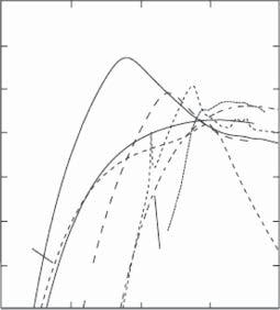
Figure1.2-2 Crosssectionsoffusion reactions.Source:Atzeniand Meyer-ter-Vehn[2].©2004Oxford UniversityPress.
dR = dn1 dn2 �� (��r )��r , (1.2-12)
where ��r = | |vr | |.
WhenEq.(1.2-12)isintegratedinthevelocityspace,thereactionrateintheunit volumeoftheplasmaandunittimeisobtainedas
R = n1 n2 ⟨����r ⟩ (1.2-13)
Here,thefusionreactivityisgivenby ⟨����r ⟩ = ∫ v1 dv1 ∫ v2 dv2 �� (��r )��r f1 (v1 )f2 (v2 ) (1.2-14)
Avelocitydistributionfunctionofthermalequilibriumisusedtoobtain ⟨����r ⟩.Going forward,thisissimplydenotedby ⟨����⟩
IntheDTreaction,sincethereactionenergy Ef = 17.6MeVisgivenbyEq.(1.2-3), thenuclearfusionpoweroutputgeneratedperplasmavolumeis
Pf = nD nT ⟨����⟩DT kEf (1.2-15)
Here, nD and nT arethedensitiesofDandT,respectively,and k = 1.60 × 10 19 J/eV, 1eV = 1.60 × 10 19 J/(1.38 × 10 23 J/K) = 1.16 × 10⁴ K.
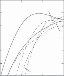
ThefusionreactivityisshowninFigure1.2-3[2].Whentheplasmatemperaturein thefusionreactorusingDTreactionisnear10–30keV, ⟨����⟩DT canbeapproximated to
⟨����⟩DT = 1.1 × 10 24 T 2 ikeV (m3 ∕s). (1.2-16)
Here, T ikeV = T i /1000isintheunitofkeV[3].
6 1CharacteristicsoftheFusionReactor Fusion cross section σ (barns) 10–4 10–3 10–2 1 10–1 10 Center-of-mass kinetic energy (keV) 1 10 100 1000 10 000 10–5 102 DT p11B D3He DD TT TT T3He D3He Li3He
Let n1 , v1 ,and f 1 (v1 )bethedensity,velocity,andvelocitydistributionfunctionof thebeamparticlesand n2 , v2 ,and f 2 (v2 )bethedensity,velocity,andvelocitydistributionfunctionofthetargetparticles,respectively.Whenparticleswithdensity dn1 = n1 f 1 (v1 )dv1 includedinvolumeelement
v1
dn2 = n2 f 2 (v2 )dv2 containedinvolumeelement
v2
vr = v1 v2
d
ofvelocityspacecollidewithparticleswithdensity
d
ofvelocity spaceatrelativevelocity
,thenumberofcollisionsoccurringinunittime, dR,becomes
Figure1.2-3 Fusionreactivity.Source:Atzeni andMeyer-ter-Vehn[2].©2004Oxford UniversityPress.
1.3PlasmaConfinementConcept
Plasmaisanelectricallyalmostneutralionizedgasconsistingofionsandelectrons. Whenplasmaisconfinedinacontainersuchasmetal,ithitsthecontainerwalland becomesaneutralgas.Therefore,variousplasmaconfinementconceptshavebeen proposedaslistedinTable1.3-1.
Theconfinementconceptsaredividedintomagneticconfinement,whichusesa magneticfield,andinertialconfinementinwhichtheplasmainertiaconfinesthe plasmabeforeitstartstoexpand.
1.3.1MagneticConfinement
Themagneticconfinementconceptshavealinearsystem(open-endsystem)anda toroidalsystem.
1.3.1.1LinearSystem(Open-EndSystem)
Thesimplestoftheopen-endsystemsisthesimplemirror.AsshowninFigure1.3-1, itconsistsoftwocircularcoils,andcurrentflowsinthesamedirection.Inthiscase, thereisanendlossfromtheopenendofthemagneticmirrorthattheplasmaleaves alongthemagneticfieldlines[4].Thetandemmirrorisanimprovementofthesimplemirror.AsshowninFigure1.3-2,theendlosscanbesuppressedbyarranging thecoilsintandem[5].
InthecuspfieldofFigure1.3-3,currentsflowintwocircularcoilsintheopposite direction.Azeropointinthemagneticfieldiscalledtheminimummagneticfield. Thisalsohasplasmaendloss.Inthe �� pinch,aplate-shapedcoiliswrappedaround acylindricalcontainer,andalargecurrentisinstantaneouslyflowedinthiscoilto induceamagneticfield,inwhichplasmaisconfinedasshowninFigure1.3-4.
Theratioofthemagnitudeofthemagneticfieldatbothendsofthemirrormagneticfieldandtheoneatthecenterofthedeviceiscalledthemirrorratio.Asthis ratiobecomeslarger,moreparticlesarereflectedatbothendsandconfinedwell. Theyin-yangcoilisacoilmadetoincreasethemirrorratio.
1.3PlasmaConfinementConcept 7
1 101001000 10–19 10–18 10–17 10–16 10–15 10–20 Ion temperature Ti (keV) Fusion reactivity 〈 συ 〉 (cm 3 /s) 10–14 p11B D3He DD TT DD p11B T 3He DT
Table1.3-1 Plasmaconfinementconcepts.
ClassificationConcepts
Magnetic confinement
Linearsystem(open-endsystem)Simplemirror,tandem mirror
Cusp
�� pinch
Inertial confinement
Toroidal system
NorotationaltransformsystemFieldreversedmirror (FRM)
Fieldreversed configuration(FRC)
Rotational transform system
Axisymmetric system
Non-axisymmetric system
Tokamak
Sphericaltorus
Spheromak
Reversedfieldpinch (RFP)
Internalconductor system
Helicalsystem (stellarator,torsatron, heliotron)
Nonplanarmagnetic axis
Bumpytorus
LaserGlasslaser
Carbondioxidelaser
Excimerlaser
ChargedparticlebeamElectronbeam
Lightionbeam
Heavyionbeam
8 1CharacteristicsoftheFusionReactor
Coil
Figure1.3-1 Simplemirror. Coil
Figure1.3-2 Tandemmirror.
Figure1.3-3 Cusp. Coil
Figure1.3-4 �� pinch. Coil
1.3.1.2ToroidalSystem
Inordertoeliminatetheendlossintheopen-endsystem,animprovedtoroidalsystem(torussystem)isconsideredbyconnectingbothends.However,asshownin Figure1.3-5a,themagneticfieldislargeatthecenterofthetorusanddecreasesasit goestotheoutsidewiththeradialdirection.ThentheLarmorradiusoftheparticle ischangedandtheparticledriftsinthedirectionasshowninFigure1.3-5b,when connectingbothendsofthetoroidalmagneticfieldsimply.Astheelectronsandions driftintheoppositedirection,chargeseparationoccurs,anelectricfieldisinduced, andtheplasmaparticlesescapeoutofthesystembya E × B drift.Inordertoprevent this,amagneticfield(poloidalmagneticfield)isneededtoconnecttheupperpart andthelowerpartoftheplasmaandshort-circuitthespacecharge.
Combiningthetoroidalmagneticfield Bt andthepoloidalmagneticfield Bp constitutesmagneticfieldlines.Whenturningaroundthetorusalongthemagneticfield line,theangleofrotationinthepoloidaldirectioniscalledtherotationaltransform angle.Thetoroidalsystemisclassifiedbythemethodofmakingthispoloidalmagneticfield,thatis,rotationaltransform.
1.3.1.2.1NoRotationalTransformSystem
Thefieldreversedmirror(FRM)andthefieldreversedconfiguration(FRC)arein thenorotationtransformsystemwithoutthetoroidalmagneticfield[4].IntheFRM showninFigure1.3-6,aparticlebeamisinjectedintothemirrormagneticfieldfrom theoutsidetogenerateacurrentinthetoroidaldirection.Apoloidalmagneticfield isgeneratedbythecurrent,andthedirectionofthemagneticfieldatthecenterof
Figure1.3-5 Charge separation.(a)Profileof toroidalmagneticfield. (b) E × B drift.
1.3PlasmaConfinementConcept 9
z R B2 E × B B 0 E + + + Ion Electron Toroidal magnetic field B
radius R (a)(b)
magnetic field
region
Major
Toroidal
Plasma
