Rail Engineer • December 2015
69
station announcements of trains approaching at over 160km/h. Initial results indicate that FOS can fulfil this requirement. Although it is not certain whether FOS can be developed to the safety integrity level required by signalling systems, this trial shows its potential for other applications in the near future. In Britain, FOS is now used to detect rocks falling onto the Oban line from the steep slopes of Ben Cruachan.
Axle counter system For signalling, the axle counter system consists of the wheel sensor, axle counters and communication with the signalling interlocking. Modern wheel sensors are mounted on the inner face of the rail below flange height. They have two upward facing magnetic coils. Wheels are detected when the voltage of the alternating current in the coils is suppressed as a wheel flange passes over them. This is not the simple piece of kit it might be thought to be. The coils need to be immune to electromagnetic interference, for which Frauscher has developed the V.Mix technology. This combines three inductive processes (inductivity, field deflection and eddy current/ hysteresis) to increase the sensor’s resistance to electromagnetic interference, linear eddy current brakes and electromagnetic rail brakes. Coils also have to operate consistently between -40°C and 100°C, despite significant changes to the conductivity and permeability of the coils’ iron cores over this temperature range. The axle counter is the electronics that interprets the wheel sensor output. To do this, the counter’s evaluation board (EB) converts analogue signals from the wheel
sensor coils to a digital pulse. As well as counting the number of axles over the sensor, the EB also detects direction and speed by comparing signals from the two wheel sensor coils. It also has a logic circuit that counts axles in and out of each signal section to determine whether the section is occupied or clear. The axle counter unit also incorporates a power supply with over-voltage protection. If not directly wired to the interlocking, it also has a communications board to transmit clear/occupied section data and receive requests for resets. Resets may be required as axle counters, unlike track circuits, do not continuously detect trains. Instead, they use logic to determine whether a section is clear using data from individual wheel sensors. When normal operation is disturbed, for example by equipment failure or engineering
work, the normal logic does not apply and a potentially disruptive system reset is required.
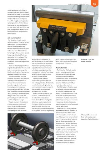
Frauscher’s RSR123 Wheel Detector.
Automatic reset The Frauscher FAdC axle counter system has a high availability as it is designed to largely eliminate such disruptive resets without compromising safety. As Phil Blacker of Atkins explained, this approach assumes that trains cannot fly or materialise out of nowhere. The FAdC system offers two ways of doing this: counting head control or supervisor track sections. The basis of counting head control is that, as the axle counter system knows where trains are, it also knows when a train is approaching a wheel sensor. Hence, it can identify wheel sensor signals that are not trains, for example maintenance trollies. Supervisor track sections are two adjacent track sections. If there is an abnormal operation of the middle wheel sensor, the sensors at each end of the supervisor section will still count the same number of axles into and out of the larger section. The supervisor track sections overlap so that each track section is part of two of them. If there is a track section fault, the sensor concerned can be automatically reset provided one of its supervisor track sections is clear. UK standards do not yet allow for axle counter resets using counting head control and supervisor track sections. However, use of these
Wheel profile camera and laser unit requires exact detection of wheel location.