


CIRAS
reporting app


reporting app


Report it in confidence, on the go.



CIRAS is the confidential safety hotline for transport. Download the CIRAS reporting app on Google Play or the App Store to raise your health, safety and wellbeing concerns. We protect your identity and share your concern with the right people, so they can act.





14|
HS2's underground heroes
Rail Engineer hails the individuals who’ve played a role in one of the high-speed network’s most complex tunnelling operations.
Senceive wireless rockfall monitoring solution
Senceive has developed a rockfall detection system for sites vulnerable to blockage or damage caused by falling rocks and debris.
Geotechnic Minimal Viable Product
Paul Darlington talks to Gerry Manley about how changes to legacy earthworks can be made safely and cost effectively.

22|
The final of the IMechE Railway Division’s Young Members annual presentation competition was held in London on 8 May.
SPL Powerlines: milestone met at East Kilbride
Regional Director Lee Pounder chats to Rail Engineer about the significant progress made during this 16-week blockade.
Re-imagining and electrifying rail freight
Rail freight has seen little innovative progress in comparison to passenger rail and infrastructure. David Shirres finds out why.
UK electrification: the messages about freight
Freight electrification must be cost-effective, incremental, and prioritised, if we are to achieve net zero, says Peter Stanton.
RIA’s promotion of innovation since 2009
RIA’s 16th Innovation Conference featured 61 exhibition stands where new ideas and strategies were showcased to the industry.
GCRE's innovation day
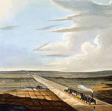
Railway 200: Creating the modern railway
Mark Phillips explores the early innovations in track design and construction that helped lay the groundwork for the modern railway.
Railway 200: 162 years of the Underground
Malcolm Dobell examines 162 years’ development of the London Underground, which has helped the capital become a world-class city.
Fleet Cyber Security
The Fleet Cyber Security Conference discussed practical measures to reduce cybersecurity risks to rolling stock fleets. Malcolm Dobell reports.
Is ETCS affordable?
David Shirres considers Scotland’s Railway, which sees the cost of retrofitting ETCS to rolling stock as disproportionate.
Planning for ERTMS and timetable implications
ERTMS and ETCS offer significant benefits but, asks Clive Kessell, have the practicalities of achieving them been thought through? 42|
An event in March hosted by GCRE highlighted the projects that have been supported through the Railway Construction programme competition.
Industry Gauging Seminar 2025
The IMechE’s Railway Division recently hosted a wellattended seminar covering the critical subject of railway gauging. Rail Engineer was there.
Easter works 2025
Major infrastructure renewals and upgrades were delivered over the Easter holiday. We provide a snapshot of this substantial programme.
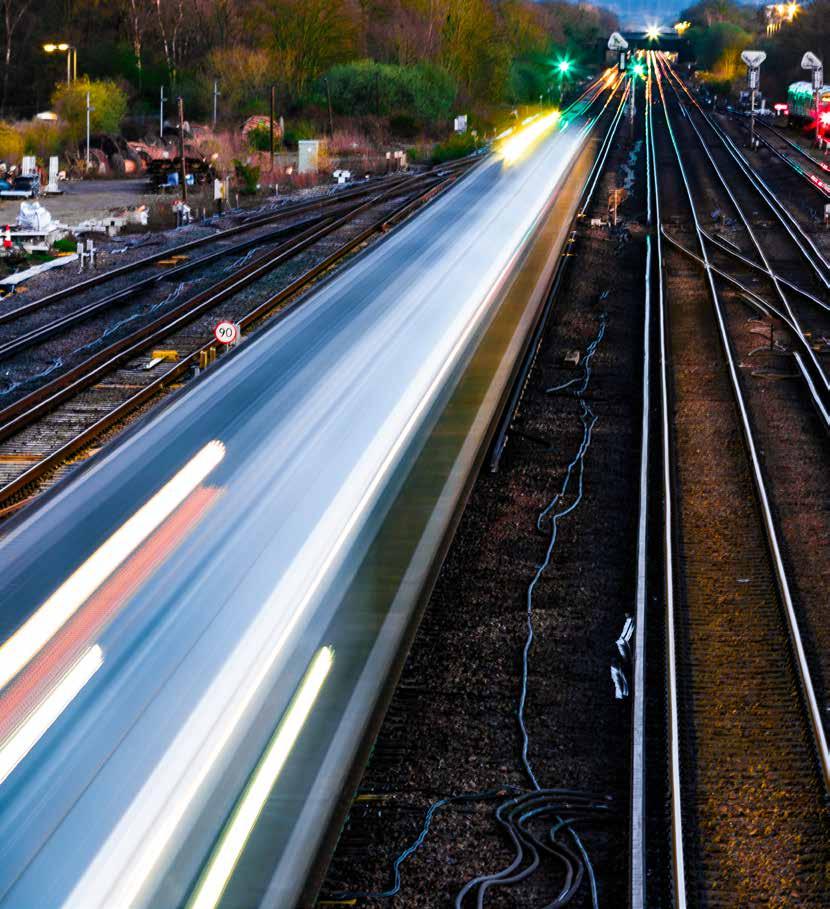
The creation of Great British Railways (GBR) to eliminate industry fragmentation by bringing track and train together has been universally welcomed. Yet it is taking some time to achieve this. Following problems implementing the 2018 timetable, Keith Williams was tasked with recommending a new industry structure. His report recommended the creation of GBR and was published as the Williams-Shapps Report (WSR) in 2021. It is likely that GBR will be created in 2027 after the Government’s Rail Reform Bill becomes law, probably in 2026.
Compared with the WSR, the public sector is to have a greater role. Another difference is that there is no longer a commitment to produce a 30-year long term strategic plan.
This is needed to specify how the newly integrated railway can be best engineered to provide the best service for its passenger and freight customers at the minimum whole life cost. This can only be done by considering trains and infrastructure as a whole system with a full understanding of the whole life costs and benefits of all possible options.
A 1999 Railtrack report on the failure to implement ETCS Level 3 on the West Coast Main Line had a useful table showing how various factors affect capacity on metro and mixed traffic railways. This showed that, while signalling can offer metros significant capacity benefits, on a mixed traffic railway signalling only offers marginal benefits. This is because the primary capacity constraints are infrastructure configuration and the route’s differing train performance and service patterns.

However, recent statements by senior figures indicate that this is not understood. In a recent interview, Lord Peter Hendy wrongly suggested: “wouldn’t you rather do that (invest in ETCS) than build third, fourth, fifth, or six tracks on major main lines.”
Furthermore, there are serious concerns about ETCS’s affordability. Scotland’s Railway, for example, considers that the cost of retrofitting rolling stock is disproportionate. As we describe, this issue is not addressed in Network Rail’s ETCS strategy. Nevertheless, ETCS does offer significant benefits, some of which are described in Clive Kessell’s feature ‘Planning for ERTMS and timetable implications.’
A further misleading statement was made by a Department for Transport (DfT) Permanent Secretary at a recent Transport Select Committee hearing who implied that the only benefit of electrification is decarbonisation. Yet this is just one of electrification’s many benefits, not the least of which is additional capacity. Mixing 110mph passenger trains with diesel-hauled freight trains that struggle to achieve 45mph on gentle gradients creates a significant capacity constraint on the congested southern part of the West Coast Main Line.
Our re-imagining freight feature shows how using electric instead of diesel freight train haulage can save one train path per train. This issue is covered further in Peter Stanton’s feature on freight electrification. This shows how electrification can deliver more capacity than ETCS. Furthermore, the industry is now able to deliver cost effective electrification as shown by Matt Atkin’s feature on the East Kilbride project. This is the latest part of Scotland’s rolling electrification programme which has been shown to reduce electrification and operational costs as well as increasing passenger numbers.
Currently, the Westminster rail investment criteria seems to be minimising capital cost with little account taken of whole life benefits. An example is the promotion of discontinuous electrification using battery trains on lines with freight or 100mph trains for which this is not an appropriate technology.
As highlighted in an article by Malcolm Dobell, gauging also needs to be considered. Although Transport Scotland’s High Level Output Statement (HLOS) devoted three pages to gauging, it is not mentioned in the DfT’s HLOS.
The above shows why GBR needs a whole system engineering strategy. This needs strong engineering leadership that considers all railway engineering disciplines to derive the best whole system approach.
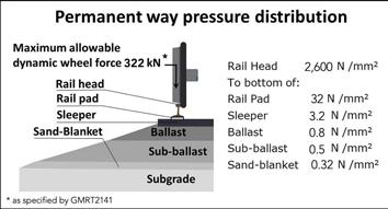
In a Railway200 feature, Mark Phillips describes the early development of railway track. The Stockton and Darlington Railway was a success because it had wrought iron rails. This is an early instance of how the railway is a highly efficient engineered system which offers many benefits, one of which is the way railway track distributes heavy loads. It seems likely that there will still be railways in 200 years time.
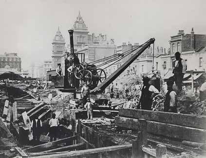
Another Railway200 feature outlines the first hundred years of the London Underground since the Paddington to Farringdon line opened in 1863. This shows how the Underground has continually evolved with innovations in tunnelling, electrification, and train design making it a world-class transportation system.
Although the early railways introduced many new technologies, today many consider that the rail industry has a poor record of innovation. Our report on the 2025 Railway Industry Association (RIA)’s innovation conference looks back at previous conferences to consider railway innovations introduced since 2011. Readers can consider for themselves whether this constitutes a poor record of innovation.
Paul Darlington describes 12 innovations that were on show at the recent Global Centre of Rail Excellence (GCRE) innovation demonstration day. These were winners of an ‘Innovation in Railway Construction’ competition, funded by Innovate UK and the Department for Business and Trade, to drive innovation in the rail industry.
With increasingly complex connected systems that needed to take advantage of such innovations, cyber security is a key issue. Our feature on the Fleet Cyber Security Conference stressed the importance of making assets secure by design.
Work valued at £87 million was delivered over the Easter weekend within 1,190 possessions across the rail network as we


DAVID SHIRRES RAIL ENGINEER EDITOR
A strategy that considers an optimum infrastructure / rolling stock solution.
describe. We also describe the work to complete the first bore of HS2’s 5.8km Bromford tunnel near Birmingham and the people involved in this work. Development of the railway’s future engineers is the aim of the IMechE’s ‘Future of Rail’ competition, which we also cover.
Specifying earthworks in a cost-effective manner is the subject of our feature ‘Geotechnic Minimum Viable Product’ which explains the techniques used to ensure earthworks are safe while budgets are reduced.
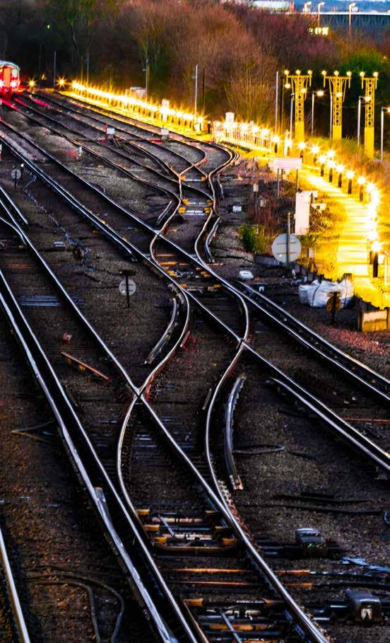
An excellent example of railway engineers delivering a cost-effective solution 40 years ago was the introduction of Radio Electronic Token Block (RETB) signalling on Scotland’s Far North line. This cost £400,000 to provide, saved £500,000 in operating costs in its first year, and quite possibly saved the line from closure.
A key test for new technology is whether it can achieve such overall cost reductions. This reinforces the need for an informed engineering strategy that takes full account of all associated costs and benefits.
Editor David Shirres editor@railengineer.co.uk
Production Editor Matt Atkins matt@rail-media.com
Production and design Adam O’Connor adam@rail-media.com
Engineering writers
bob.hazell@railengineer.co.uk
bob.wright@railengineer.co.uk
clive.kessell@railengineer.co.uk
david.fenner@railengineer.co.uk
graeme.bickerdike@railengineer.co.uk
malcolm.dobell@railengineer.co.uk
mark.phillips@railengineer.co.uk
paul.darlington@railengineer.co.uk peter.stanton@railengineer.co.uk
Advertising Craig Smith craig@rail-media.com
Gary Simpkins gary@rail-media.com
Rail Engineer
Rail Media House, Samson Road, Coalville Leicestershire, LE67 3FP, UK.
Switchboard: 01530 816 444 Website: www.railengineer.co.uk
Rail Engineer Videos http://rail.media/REYouTube
Editorial copy to Email: news@rail-media.com
Free controlled circulation Email: subscribe@rail-media.com
The small print
Rail Engineer is published by RailStaff Publications Limited and printed by PCP Ltd.

© All rights reserved. No part of this magazine may be reproduced in any form without the prior written permission of the copyright owners.
Part of: www.rail-media.com
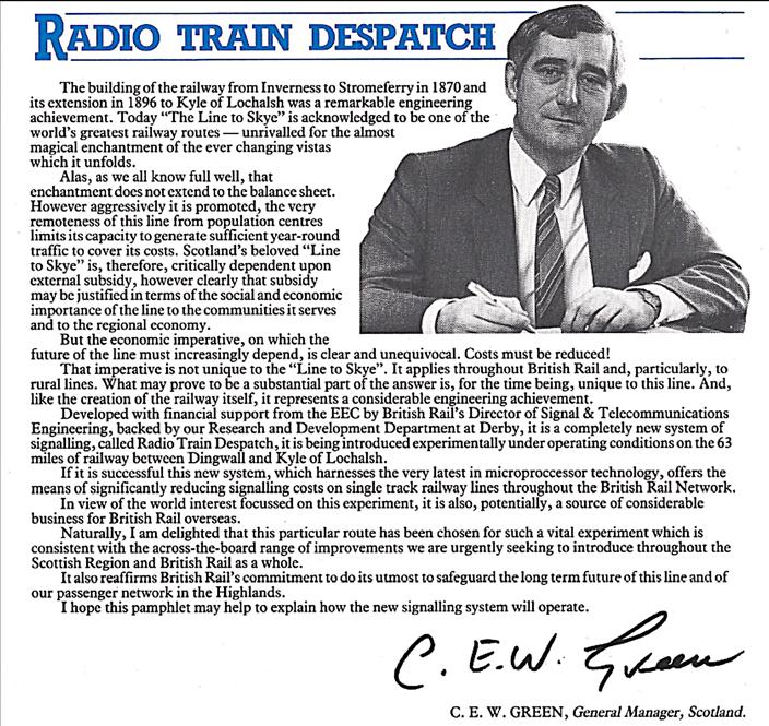
In 1985, Radio Train Despatch, technically known as ‘Radio Electronic Token Block’, was introduced on the single line between Dingwall and Kyle of Lochalsh.
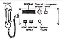
Prior to the introduction of RETB, a driver could not proceed onto a single line section unless the signaller had given him/her a brass key token for the section. RETB replaced this brass token with an electronic token issued by the Dingwall control centre, to a cab display unit which displays the section for which the driver has authority.
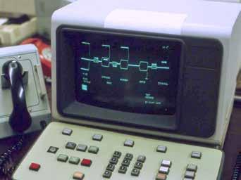
This token is coded to ensure it can only be received by the locomotive for which it is intended. Microprocessors control the interlocking and provide the signaller with a visual display of the traffic on the line
It cost £400,000 to introduce this system on the Far North Lines which, by eliminating signalboxes, saved £500,000 in operating costs in its first year.
Rail Engineer is grateful to the Friends of the Far North Line for their permission to reproduce part of the pamphlet issued by ScotRail to mark the introduction of RETB.
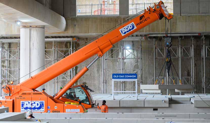
On Thursday 29 May, HS2 revealed the first section of platform to be installed for Britain’s new high-speed railway.
In the underground box at HS2’s Old Oak Common station, engineers have begun installing the platform slabs which passengers will use when boarding or alighting high-speed trains in the future.
Six platforms are being built at the super-hub station in West London for high-speed services. Each will be served by HS2’s fleet of 400-metre trains.
These are being built in advance of a further eight surface-level platforms for Great Western Mainline, Elizabeth Line, and Heathrow Express services.
All six high-speed platforms are being installed at the same time, with construction taking place from either end of the station box. They are laid out as three ‘island’ style blocks.
The platforms are the first to be unveiled anywhere on Britain’s new high-speed railway and give a glimpse of what future passengers can expect when services begin running.
To construct the platforms, 1.59-metre-high invert walls have been poured. 1,960 pre-cast concrete slabs, measuring up to 4 metres by 2 metres, are then lifted into place on top with a void below to allow installation of services.
The pre-cast concrete slabs are being made offsite by Explore Manufacturing in Worksop, Nottinghamshire, an example of how Britain’s manufacturing industry is building for the nation’s future.
The structure of the huge 850-metre-long underground station box at Old Oak Common was completed this year, including the 45,000-square-metre base slab. The station is being constructed by HS2’s station construction partner, Balfour Beatty VINCI SYSTRA (BBVS JV).
Huw Edwards, delivery director for stations and placemaking at HS2 Ltd, said: “The installation of the first passenger platforms represents a real step forward in taking HS2 from purely a construction project to the future of Britain’s railways.
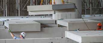
“Whilst there is still much more work to do, standing where passengers will alight HS2 services is a reminder of what this railway will achieve - creating connections between people and places, that will benefit generations to come.”
Steve O’Sullivan, Balfour Beatty VINCI SYSTRA project director at HS2 Old Oak Common station, commented:
“The installation of the first high-speed platforms at Old Oak Common marks a defining moment in the delivery of HS2. It’s a powerful symbol of progress, not just in terms of engineering, but also highlights the change in project focus from the current civil phase of the works to the building, fit-out, and the mechanical, electrical and public health phase of the works. Our teams at BBVS are proud to be laying the foundations of what will become one of the UK’s most important interchange transport hubs.”
Later this year, HS2 will begin installation of the eight platforms that will be used by conventional rail services – the Great Western, Elizabeth Line, and Heathrow Express. The BBVS JV team is also working a level above the base slab where the platform construction is taking place to construct the ground floor level of the station. From there, the superstructure of the station can be built, creating the vibrant station environment.
Tunnelling work to connect the station to the HS2 network is being undertaken by HS2’s London tunnels contractor, Skanska Costain STRABAG JV. In the eastern section of the underground box, the team are preparing to launch two giant tunnelling machines towards Euston.
In the western side of the box, the team will excavate a short tunnel connecting the station to the Victoria Road Crossover Box nearby using the sprayed concrete lining method. From there the new high-speed line will run through the Northolt Tunnel.
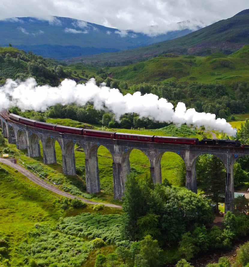
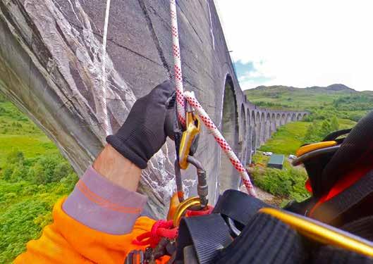
The iconic Glenfinnan Viaduct in the Scottish Highlands, made famous worldwide by the Harry Potter films, has undergone an extensive, £3.4 million maintenance programme to safeguard its future for generations to come.
Network Rail, along with principal contractor AmcoGiffen, assessed the condition of the viaduct. Concrete repairs were carried out across the structure sympathetically, taking care to replicate its heritage appearance. New safety handrails for staff working at height were installed, along with renewing ballast retention systems at the ends of the structure.
Engineers also worked in the River Finnan, protecting the piers from erosion caused by the fast-flowing river. Meanwhile, rope access technicians descended from the viaduct, reaching and restoring areas that would otherwise be inaccessible.
Laura Craig, scheme project manager at Network Rail, said: “This project was years in planning due to the complexity of navigating such a large-scale, historic structure. Our highlyskilled team faced numerous challenges, from preserving the viaduct's original integrity to implementing modern engineering solutions. Every step of the process required meticulous attention to detail and a deep respect for its heritage.
“It’s an honour to look after the Glenfinnan Viaduct, knowing how much it’s loved all over the world. We’re proud to see it standing strong and it’s a testament to the dedication and hard work of everyone involved.”
structure
The Glenfinnan viaduct opened in 1901 and is the largest mass concrete viaduct in Scotland, spanning more than 1,000 feet. The build cost £18,904 at the time, around £2 million in today’s money.
Historic Environment
Scotland has designated the structure as Category A, the highest level, meaning it’s of significant architectural and historical interest. As part of its preservation, Network Rail refrains from cleaning off efflorescence marks from the rain as it drains through, ensuring the character of the structure remains.
Ann MacSween, head of planning, consents and advice services at Historic Environment Scotland, said: "We welcome Network Rail's investment into the careful repair of this iconic structure.
“Glenfinnan is the most impressive of several mass concrete railway viaducts and bridges along the West Highland Line, which was built 1897-1901. These bridges were mostly designed with an exposed concrete finish, rather than being faced in stone, and are the earliest railway bridges of this style in Scotland.
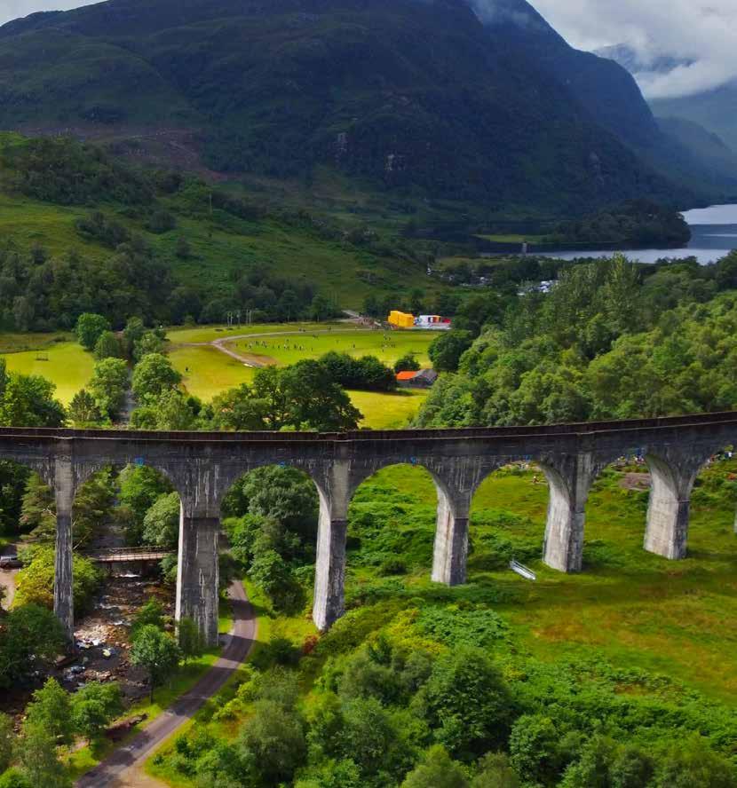
“Over a century after it was first built, Glenfinnan Viaduct still stands strong today, in no small part due to Network Rail's excellent care."
The viaduct is an icon of Scottish tourism, drawing thousands of visitors each year. Many pass over the arches aboard ScotRail trains, as well as the ‘Hogwarts Express’ Jacobite steam train operated by West Coast Railways. Countless more tourists make the trip to Glenfinnan to admire the spellbinding views from the ground.
James Shuttleworth, West Coast Railways’ commercial manager, said: "Having run ‘The Jacobite’ for over three decades and celebrated its centenary in 2001, we truly appreciate the historic significance of the viaduct. The recent restoration work has further highlighted its importance, not only as a vital piece of railway heritage, but also as a beloved film star in Harry Potter, for which we
proudly provided The Hogwarts Express."
The restoration of the viaduct is part of a broader programme of work in the Glenfinnan area.
A two-year, industry-leading pilot project enhanced the natural habitat by planting
trees across approximately 200 hectares to protect, restore and expand rainforest and peatland habitats. Additionally, deer fencing has been installed at Ardmolich to safeguard the newly planted native woodlands from overgrazing.
HS2 celebrated another construction milestone on 9 May when the 1,600-tonne tunnel boring machine (TBM), Mary Ann, broke through at Washwood Heath, Birmingham, marking the end of her mission to excavate the first bore of what will soon become the longest railway tunnel in the West Midlands.
The 125-metre-long machine began constructing the 3.5-mile (5.8km) Bromford Tunnel, which starts at the Warwickshire village of Water Orton and extends to the northeast Birmingham suburb of Washwood Heath, in July 2023.
The result of years of meticulous planning, the undertaking required pinpoint precision, flawless preparation, and a highly committed team. Led by HS2’s West Midlands contractor Balfour Beatty VINCI, a 450-strong team worked around the clock for just under two years.
During the 22-month-long mission, the team on board the machine spent 649 days and nights working at depths of up to 40 metres, navigating Mary Ann under the Park Hall Nature Reserve, the M6 motorway, and the River Tame – which crossed the tunnel four times, with a headspace as low as five metres.
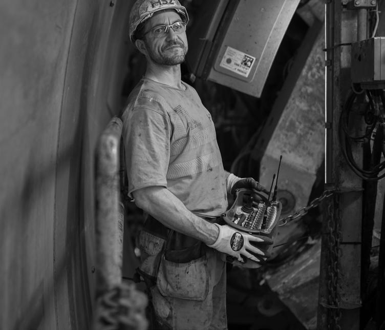
It is fitting, then, that we celebrate the magnificent achievements of the individuals who’ve played a role in one of the most complex tunnelling operations on the entire HS2 network. Here we give some of those inspiring individuals a voice and cast a spotlight on their role in the project.
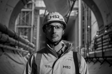
The team was led by Tunnelling Director Jules Arlaud (pictured right). Jules was mobilised to the West Midlands when BBV’s first giant tunnelling machine arrived from Germany. He already had a string of successful worldwide missions under his belt and his next challenge was to join –and eventually lead – the team responsible for constructing two of the five twin-bore tunnels on the HS2 network.
“It’s been a challenging drive beneath critical live infrastructure and through complex ground conditions,” says Jules.
“I’m incredibly proud of our entire team, whose expertise, dedication and resilience have made this possible.
“This achievement follows years of design, planning and preparation from BBV, in close collaboration with HS2 and our partners. The team will now move onto the next phase of work inside and outside of the tunnel, while our second TBM, Elizabeth, has completed 60% of the second drive.”
At the coalface
A team of 16 worked the TBM with 61-year-old Lead Miner Steve Rocke in charge. After 43 years on the job, this was his last assignment, after which he returned to his family in Hull, and his beekeeping hobby.
Pilot Harsh, from Kolkata, works in tandem with Steve. They share a tiny office space with three crew members who monitor the technical and mechanical side of the drive. If the cutterhead needed repairing or maintaining, one of the miners must enter the excavation chamber to fix

it. “It can be like working inside a balloon,” says Steve. “So, we calculate to the second how long they’ve got.”
Air pressure levels inside the tunnel determine whether a hyperbaric intervention is required on the miner’s return and Tunnel Agent Josh Knight makes that decision. He assesses the miner’s safe working time and calculates how long he must spend in the decompression chamber afterwards. From a mini submarine-like space inside the TBM, the miner must inhale pure oxygen to avoid the painful decompression sickness, known as the bends.
“Hyperbaric interventions don’t happen often”, explains Josh. “Thankfully, we’ve only had to do it once so far on this mission.”
Around one million tonnes of spoil were excavated during Mary Ann’s 3.5-mile drive, and those at the back of the operation are just as integral to the machine’s daily advance. As the cutterhead rotates, excavated material is extracted and mixed with slurry. The solids and liquid are then separated at an on-site slurry treatment plant.
The treatment plant is where most new starters learn the ropes and is where
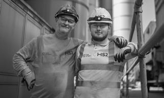
21-year-old Dylan Kehoe works alongside his father, Greg. The duo (pictured above) from South Wales moved to nearby Minworth to work on HS2.
Dylan was recruited by Solihull-based Rorcon, as part of the drive to upskill a new generation of tunnellers. After an initial stint as a labourer, the company supported him to achieve his Level 3 Supervisor NVQ, enabling him to climb the ladder to treatment plant operative. The experience has left him hungry for more.
“If you work hard, the progression opportunities are there,” said Dylan. “I’ve worked my way up from being a labourer and hope to progress into mining next, so I can work on the tunnel boring machine.”
During his 40-year career, Dylan’s father Greg has worked on some of the UK’s biggest tunnelling projects, from Crossrail to the London super sewer, Tideway. He, Dylan, and Erdington-based new recruit Edward East worked in sync to keep pace with the TBM’s miners.
Every tonne of excavated earth is compressed to extract the groundwater. Recycled slurry is pumped to the front of the giant digging machine to maintain ground pressure, while the excavated material goes back to the treatment plant and through the slurry circuit. The trio monitors the vast network of machinery that controls the pressing, dilution, and pump process, and are in constant contact with the TBM team underground. The miners need to know the water’s coming and rely on Greg’s analysis of the ground conditions.

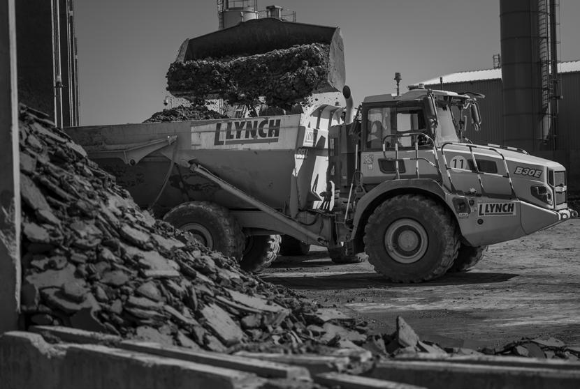
“The toughest bit is keeping pace with the mining,” explained Greg. “It’s a balancing act to keep the water tanks at the right level, so we’ve got the volume we need for the machine. Too much, or not enough is never a good thing.”
Subterranean support
There’s little glamour in tunnelling. Whether onboard the giant moving factory, or supporting the machine’s drive from the rear, the team works long, hard hours. Seven 12-hour shifts are rewarded with a three-day break, then it’s another stint of 7/12s before a long awaited fourdays off.
The same is true for the ring builders and grouters who scurry along the metal stairwells and corridors. Excavating the ground is just one part of the job - Mary Ann must also build the tunnel. At peak production, the TBM advanced at around 30 metres per day, lining the tunnel with segments to form precision-placed concrete rings.
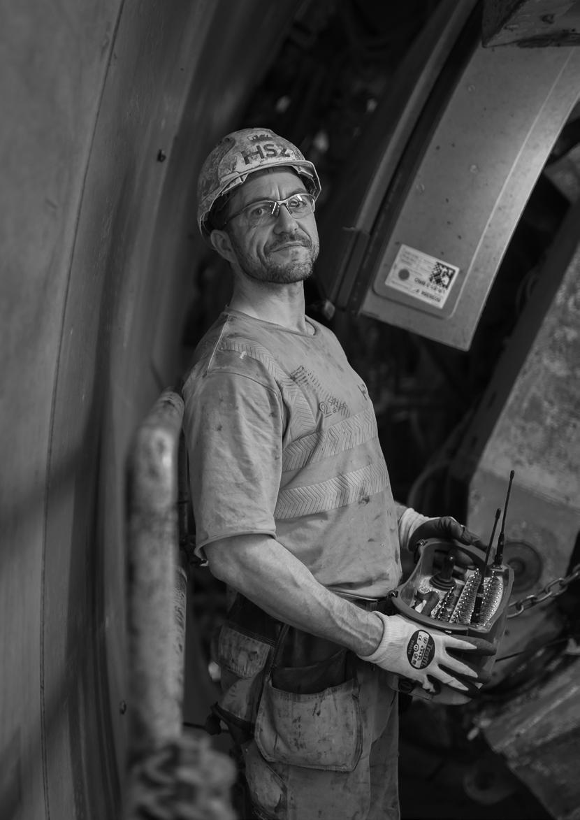
Gary Jones (pictured right) and his two-man team dictated the installation of 20,000 of these precision-designed segments, manufactured at Balfour Beatty VINCI’s pre-cast factory at Avonmouth near Bristol.
Crane operators lifted and loaded the huge concrete segments onto an electric vehicle (EV) which was driven into the tunnel. Gavin Davis from Doncaster was at the wheel. Years of experience have earned him the accolade of being the only driver that can manoeuvre the 16-wheel EV in a three-point turn. When he arrived with another haul of segments, Gary and his crew lifted, shifted, and locked them into place.
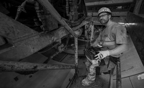
“On a good shift, we’ll build five or six complete rings,” explains Gary. That 2,971 rings were required in total gives a sense of the scale of the task.
The grout which seals the segments into place is made at the onsite batching plant. Tunnelcraft Apprentice Jevon Lynch, recruited at an HS2 careers fair, was rewarded with a permanent job running the grout batching plant after passing his Tunnelling NVQ.
“I’ve done a bit of everything in my twoyear apprenticeship,” says Jevon,” from helping to build the TBM to working with the crew onboard. Getting a permanent job sets me up for a career in the industry, which is exactly what I need with a baby on the way.”
Despite its most recent success, it’s not the end of the project for our tunnelling heroes. TBM Elizabeth is already hard at work on the second drive of the Bromford
Tunnel and her breakthrough is expected later this year. Once complete, Bromford Tunnel will be the longest railway tunnel in the West Midlands and, in the not-toodistant future, will be used by millions of passengers travelling to Birmingham’s new terminus station – Curzon Street –just two miles away.
The Washwood Heath site, where Mary Ann broke through, and covered by Malcolm Dobell in Issue 208 (MayJune 2024), will become the nerve centre for HS2’s operations. Next to the tunnel portal, HS2’s Depot and Network Integrated Control Centre will be built. From this site, trains will be serviced and stored, and the real time operation of the railway will be controlled.
Rail Engineer celebrates the efforts of all involved and salutes their continued grit and determination under some very difficult conditions. Here’s looking toward the second breakthrough at this critical site.

Engineers at Senceive have developed a rockfall detection system for sites considered vulnerable to blockage or damage caused by falling rocks and debris.
While the UK rail network does not generally face the same degree of risk from rockfall as some European routes, for example those in the Alps and Pyrenees, a significant number of rockfall events each year cause delay, disruption, and danger.
It is 20 years since the Milton Keynes-based remote monitoring specialist pioneered wireless monitoring applications for the rail sector and 10 years since its first successful application of the now widely adopted InfraGuard™ slope monitoring technology at Barnehurst in South London.
The rockfall solution uses intelligent slope monitoring features built into InfraGuard to address the unique challenges posed by rockfall hazards, providing near real-time detection of sudden events, rapid alerts, and high-quality photo verification for quick, actionable insights.
Robust & reliable
Rock slopes, unlike soil slopes, are characterised by the unpredictable movement of individual boulders or localised debris, which can be missed by a typical wireless slope monitoring system because material can fall in between tilt sensor locations. This poses a significant threat to railways, and a bespoke solution was needed. Enter Senceive’s latest development, created in close collaboration with Network Rail, the world’s largest user of wireless slope monitoring technology.
In early 2024, Network Rail commissioned trials at a test site in Switzerland, which allowed Senceive to demonstrate an innovative wireless detection system specifically tailored for rocky slopes. The system revolves around monitoring the effects of rockfall debris impacting fences and barriers and provides a robust, reliable solution with a high detection rate and a minimal incidence of false alarms.
Events can be detected in three ways:
» Rockfall detected by draw wire sensors. This method is based on sensors detecting the extension of draw wires fixed to the fence as a result of loading by rockfall debris. It is particularly sensitive to the gradual accumulation of material over an extended period.
Site trials in a Swiss quarry allowed various boulder impacts and sensor configurations to be evaluated.
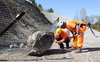

Fences, barriers and netting do not always prevent material encroaching on the track.
» Impact on catchfence detected by tilt sensors. This approach is based on impact sensors in the Senceive NanoMacro tilt nodes mounted on catchfence stakes detecting a sudden acceleration or shock. It is ideal for detecting instantaneous events such as a small-to-medium sized boulder hitting the fence.
» Rotation of catchfence stakes detected by tilt sensors. This approach is based on the detection of rotational movement by the highly sensitive tilt sensors in the same NanoMacro nodes described above. Because it requires movement of the catchfence stakes, it is the most reliable way of detecting a large-scale rockfall event that hits the fence with significant force.
An event detected by any of these three methods will trigger the system to accelerate reporting and send high-resolution site images. Equipped with cameras capable of detecting football-sized objects from 50 metres in any lighting conditions, this system enables rapid decision-making, helping to significantly reduce the risk of infrastructure disruption, accidents, and derailments.
Resilient infrastructure
Senceive Nano tilt sensors mounted on a catchfence protecting an Austrian railway.
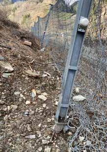
Built for the most rugged and remote locations, the wireless monitoring solution operates independently, requiring no external power or fixed communications infrastructure. This makes it an ideal choice for deployment in challenging, inaccessible areas where rockfall presents a serious risk to rail infrastructure. It is a modular system and can be fitted to virtually any fence.
A recent deployment in the north of England was achieved within a few hours using plastic mesh fence supported by steel stakes. Tilt nodes were fixed to the stakes, a wireless cellular gateway was added, and the system was reporting data before the team left site.
By integrating these detection capabilities with proven technology, Senceive’s rockfall monitoring system allows operators and engineers to respond quickly and effectively to rockfall hazards, ensuring safer, more resilient infrastructure.


Railway asset engineers and their project colleagues currently face a huge challenge to keep the railway safe and reliable, with a budget said to be 25% less than what is required to maintain the current asset condition.
All asset types face the same challenge, but geotechnical earthworks face another challenge with climate change and the need to keep the assets safe in the extreme weather events we are experiencing. Not only do the existing earthworks need to kept safe, but they also have to support change with for example new electrification schemes. This can require a combination of elements including new Overhead Line Equipment (OLE) structures; bridge works – reconstruction, jacking, and parapet raising; track –lowering, lifting, and slewing; and signalling, with new signals and signal gantries.
All this has to be delivered on an asset which in many cases does not comply with modern geotechnic standards. There are
over 190,000 earthwork assets (approximately 19,000km) which were constructed well before the development of geotechnical engineering techniques. Earthwork construction during the 19th century was undertaken on a huge scale, which has left a legacy of over-steep embankments and cuttings, made with questionable construction techniques.
‘Embankments and cuttings on the early railways’ By A.W. Skempton, says that: “Thomas Telford’s report (1829) on a railway embankment, clearly shows they were formed by end-tipping at the full height; a process, moreover, of which Telford specifically disapproved on the grounds of delayed consolidation and an increased tendency for slipping.
“Shortly after opening the line another very similar slip occurred… as a quick first-aid measure Brunel had a row of timber piles driven at the toe of the slope, penetrating 8ft into undisturbed ground”.
To make matters even more challenging, Rail Engineer reported in December 2023 how historic mining features affecting railway earthworks must be managed safely and efficiently to ensure projects such as new electrification can be delivered cost effectively. Rail Engineer recently met up again with Gerry Manley, to learn how changes to earthworks can be made safely and cost efficiently to accommodate electrification work on the Midland Main Line, and the concept of a Minimum Viable Product (MVP).
Minimum Viable Product
There are several ways that mining risk to legacy earthworks can be managed during construction projects, and it is something which can be very time consuming and expensive. The MVP principle
however is that a project can only deliver interventions to meet the client’s requirements, standards, legislation, and budget.
The term MVP came from the production industry and is a version of a product with just enough features for it to be usable. It aims to avoid over engineering products and to minimise cost. It contrasts with the traditional ‘stealth mode’ method of product development, where businesses make detailed plans for products, spanning a considerable time period and incurring huge costs.
Rail needs to be an affordable option for travellers and freight operators, otherwise customers will use other modes of transport which are not as inherently safe or carbon friendly. So, over engineering rail assets can result in increasing the overall societal risk of transport. This is why cost must always be a factor in managing safety and is a fundamental part of So Far As Reasonably Practical (SFARP) legislation and MPV.
The Construction (Design and Management) Regulations 2015 (CDM 2015) also recognise SFARP and say that the principal designer must, as far as reasonably practicable, ensure the elimination of the risks associated with the design. If this is not possible (for instance because of disproportionate costs) then the remaining risks must be reduced or controlled. This is also one of the founding principles behind the management of mining risk for electrification projects and an MVP.
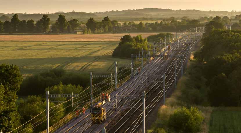
The Midland Main Line (MML) electrification is a significant upgrade to the railway which has been ongoing since 2015. The project involves electrifying sections of the line to allow electric trains to operate, thereby supporting the UK Government's environmental goals and improving the overall efficiency of rail transport.
The electrification is part of a broader initiative to modernise the rail network and reduce reliance on diesel engines. Gerry explained that an early mining report of just one short 2.4km section of Route Section Three from Syston North Junction to Sheet Stores Junction and Trent Sidings, suggested that 100 bore holes would be required to determine the mining risk. This could have cost approximately £4 million and had significant programme impact. However, using the Guidance for Electrification in Mining Risk Areas & Associated Civils (Issue 205, Nov-Dec 2023) and applying MVP avoided the need for the time consuming and costly bore holes, while managing the risks arising from electrification work on the existing assets, including earthworks, in an area with a mining history.
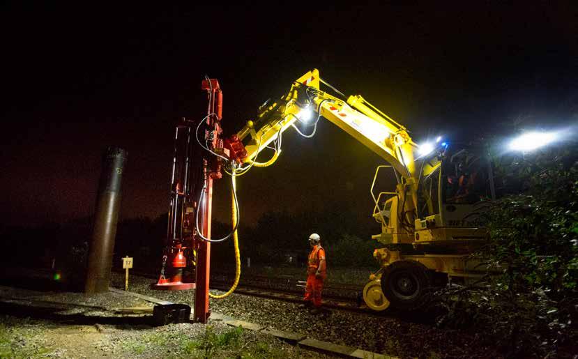
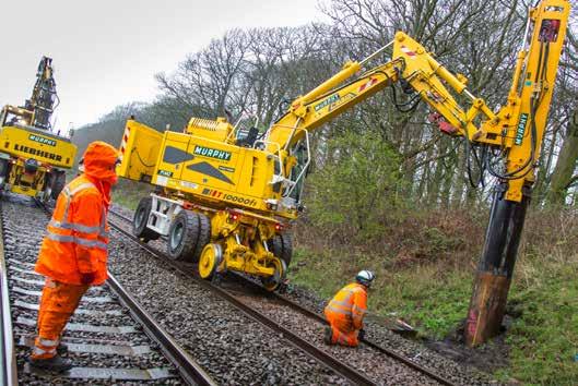
The foundations for new OLE structures can be split into two groups, either laterally loaded piled foundations or vertically loaded pad foundations, including mass gravity foundations.
Laterally loaded piled foundations are the most common, so these should be considered first. These are typically either driven / vibrated Circular Hollow Section (CHS) piles or augered. Augered piles take longer to install and
are more expensive than CHS. Therefore, in the absence of significant mining issues, CHS is generally the more attractive option and offers best value. However, where there are noise or vibrational concerns, augered piles may be more appropriate. If there is evidence to indicate mining void migration and/ or Loss of Surface Support (LoSS) in the area, this needs to be considered and, where appropriate, low vibrational auguring may be considered. Pad foundations are more expensive, time consuming, and disruptive to construct than either CHS or augered piles, but they may be appropriate where shallow bedrock prevents piling or the use of Overhead Line Equipment Master Index (OLEMI) side bearing foundations, for example. On earthworks, pad foundations also impose their load vertically directly onto the top of embankment slopes, where laterally loaded piles have nominal vertical load making them much more appropriate.
Gerry explained that there has been much discussion over the years on whether laterally loaded piles in embankments should be designed to withstand earth pressures in the event of embankment instability. However, this would result in significant increase in size of foundation, and substantial cost escalation, required to essentially allow a failing embankment
to ‘flow’ around the pile foundation. There is little benefit to be gained following a landslip from having a vertical OLE stanchion with the track ‘hanging in the air’. Plus, the prediction of which earthworks will be prone to future instability is not an exact science, but rather sound engineering judgement of what could happen.
So, a leaning OLE stanchion can prove a very useful indicator of potential earthwork instability before any effect on track is evident and impact on the safe operational railway. Therefore, not only would designing piles to accommodate such loads result in substantial cost increase and be contrary to MVP, but it would also remove a potential valuable early indication of earthwork movement.
Trials were undertaken on the Transpennine Route Upgrade West projects looking at the risk of mining to electrification schemes. This established that, where the depth to bedrock exceeds 20 metres, CHS piles were appropriate in similar ground conditions without the need to consider mining risk any further. Where depth to bedrock is less than 20 metres, further consideration of other factors is required, to determine whether CHS piling is within acceptable risk limits. These include: (i) whether the stiff glacial till is ≥ 10 metres thick (a glacial till is a
product of the glacial processes and are complex, hazardous soils); (ii) if multi-seam extractions are present; and (iii) if worked seam strata dip > 20°. The trials also established that auger pile construction vibration was significantly less than that from typical railway traffic.
There are a range of options available for new signal structures. These range from straight post, cantilever, and gantry. There are also various foundation options, from mass gravity pads, screw piles, CHS piles and augered piles.
For cantilever and gantry structures, foundation options are very similar to those for OLE structures, including typically up to six-metre pile length. Generally, on an electrification scheme there are very few new signal structures compared to the number of OLE structures. Therefore, where possible, employing the same foundation type could be advantageous and cost effective as they can be installed with the same resources and in the same time frame.
In cuttings and level ground, and on embankments with sufficient cess width for pad foundation, straight post signal pad foundations do not
typically exceed 1.5 x 1.5 x 1.2 metres deep, and are therefore considered ‘lightweight elements’.
For straight post signals on embankment crests or upper slopes, pad foundations may be difficult to construct, so CHS, augered or screwed piles are likely to be more appropriate.
The concept of a Geotechnic MPV approach for electrification project work is a very welcome initiative to provide a more consistent mature ALARP and effective approach to managing mining risk.
In the years ahead there will need to be significant efforts and resources required to manage earthworks. However, there is likely to be an unprecedented level of competition for funding, between different assets and regions within Network Rail, and competition between railway funding and other public funding. The industry needs to identify new ways of working, like the geotechnic MPV to drive down cost, and it cannot afford to remove every risk on the network. Otherwise, there will be no investment and routes will close.


DAVID SHIRRES
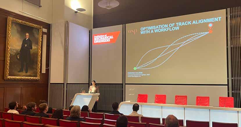
Fareena Saleemi gives her presentation under the watchful eye of George Stephenson.
The final of the Institution of Mechanical Engineers’ (IMechE) Railway Division’s Young Members annual presentation competition – The Future of Rail – was held in London on 8 May. The competitors were winners of heats held at the Railway Division’s centres throughout the UK and were competing for a prize of £1,000.
The competition is open to all young railway engineers including apprentices, undergraduates, and those in the early stages of their career. Entrants must deliver 10-minute presentations about their contribution to work in any aspect of the rail industry and which can describe project work, research, technical developments, or novel technology.

The event started with heats run by the Railway Division’s Scottish, North West, Midlands, South West, and South East Centres in February and March at which over 20 young engineers gave presentations on a diverse range of topics. The final was held at the IMechE’s imposing headquarters at Birdcage Walk in London. It was organised by the Railway Division’s Young Members (RDYM) committee and hosted by its vice-chair, Ellie Smith.
Winner of the North West Centre’s heat was software engineer Kathryn Hurst of Digital Transit. She gave her presentation on the Tram Overspeed Advisory Device (TOAD) which she produced for Blackpool Transport. This enabled the town’s heritage trams to comply with the recommendations of the RAIB report into the Croydon tram crash in respect of an in-cab overspeed warning. To do so, TOAD had to be small and easy to install, be powered from the tram’s 24v DC system, have a speedometer, and provide an in-cab warning.
Kathryn described how geofences were set up and defined in a configuration file so that if a tram approached them at an excessive speed
an alarm would sound. She described how the microprocessor was coded, the components required and how the system was tested. After first producing a proof-of-concept prototype, testing, driver feedback and experience, two further design iterations were required before the design was finalised. However, production of the final design is currently on hold while Blackpool Transport have suspended heritage tram operations.
Ewan Martin, a project engineer from Brodie Engineering (Scotland) described his role in the C8 overhaul of a Class 180 diesel multiple unit. This involved revising block cards to provide more detail to track the work, providing engineering support, liaising with stakeholders and reviewing progress.
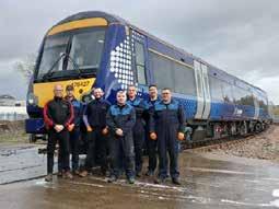
As there were only three days to complete the overhaul’s 14 jobs, timely engineering advice was essential, this included clarifying specification of relays and relocating door button earth studs. To communicate this advice, Ewan trialled new ways to improve communication. He felt he had learned much from this project, not the least being that as nothing and nobody is perfect, and processes and people can always be better.
Next to give a presentation was Fareena Saleemi, a graduate track engineer working for WSP who won the South Eastern Centre’s heat. Her presentation was entitled ‘Optimisation of track alignment with a workflow’. She noted producing an optimum track alignment starts with defining standards and identifying constraints. However, ensuring this is exhaustive while being flexible to changed initial requirements can be quite challenging. Hence her presentation considered how software can simultaneously evaluate multiple track alignment options.
Fareena explained that as constraints are not all absolute, weighted factors such as cost, operational efficiency, safety, and sustainability need to be considered for each alignment option. She illustrated her presentation with
a brief to develop a new 1,000km passenger railway between Quebec City and Toronto which required the analysis of 28,000 square miles of land with lakes, wetland, and rivers for which there were numerous valid alignments. Using automation, the options that best addressed these constraints were quickly identified. Hence, she had no doubt about the benefits of using automation in this way at the early stages of a project lifecycle.
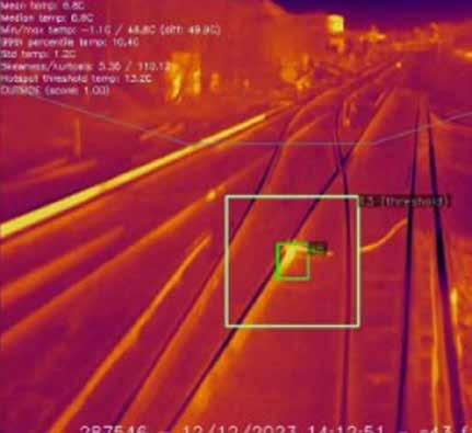
Winner of the South West Centre’s heat was Aamina Shah, a systems engineer from Angel Trains. Her presentation was entitled ‘Hot or Not? The Use of Thermal Cameras in Third Rail Monitoring.’ Aamina advised that thermal imaging cameras can be used to detect loose and defective third rail components, as well as faulty braking equipment on passing trains. When monitored over time thresholds can be developed to allow machine learning to automatically determine the requirement for rapid defect response or preventative maintenance.
Aamina’s presentation explained the practicalities of fitting both removable and fixed front facing thermal imaging cameras to Class 507 and 707 units which concerned power supplies, water ingress, and calibrating them to take account of emissivity of third rail components. These cameras were used in conjunction with a forward-facing video camera and an Automated Intelligent Video Review system to produce the required alerts and reports. It was found that this system effectively detected defects which included a defective lug with a 48°C temperature exceedance.
An everday occurrence
The final contestant was Shahrukh James, a system engineer from Alstom who had won the Midlands Centre’s Future of Rail heat.
His presentation had the intriguing title of ‘An everyday consequence and its impact to the £18.9 billion railway’. The Elizabeth line was the railway concerned, and the everyday occurrence was dropping litter, specifically by train doors. Litter affecting door incidents had caused 87 incidents over a four-month period making this by far the most significant cause of delay.
Shahrukh explained that the first attempt to solve this problem was the provision of a 3D-printed deflector which was only partially successful. Attention was then turned to the door leaf monitor switch which was being activated by litter when the door was open. It was therefore considered that a software change was needed to desensitise this switch so that it would not activate when the door was in the last 300mm of its opening cycle or the first 300mm of its closing cycle. He advised that this combination of hardware and software changes eliminated this door litter problem.
Deliberations and a result
Following the presentations, the judges retired to deliberate. They were: Tom Scott of Angel Trains (RDYM chair); Farzana Hampshire (RD Board); Callum Nicolson of Vanguard STS (last year’s winner); Oliver Joris of Ford Motor Company (IMechE Young Members Board Chair); and Mark Elliot of Network Rail (Railway 200).
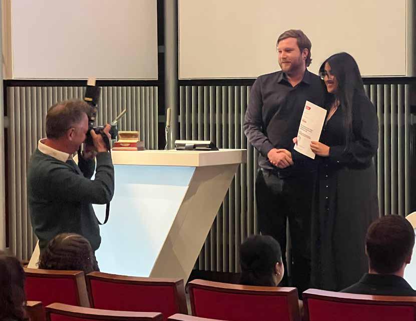
Tom Scott commented that, given the quality of the presentations, the judges had had a difficult task choosing the runners up and the winner. Announcing the results in reverse order, the second runner up was Ewan Martin, the first Runner up was Shahrukh James, and the winner was Aamina Shah. As they do every year, the industry’s young engineers excelled themselves throughout the heats and at the London final. Their presentations gave a fascinating insight into the impressive work by young engineers across the country, who are the future of rail.
Any young engineer who would like to enter the 2026 competition should contact their local Railway Division Centre, details of which are available at the very bottom of the link below: https://www.imeche.org/industry-sectors/ railway/railway-division-how-we-are-governed


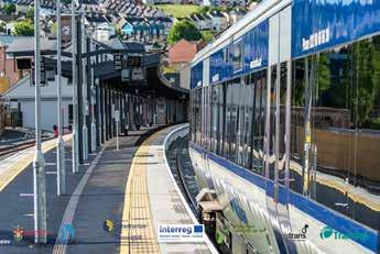








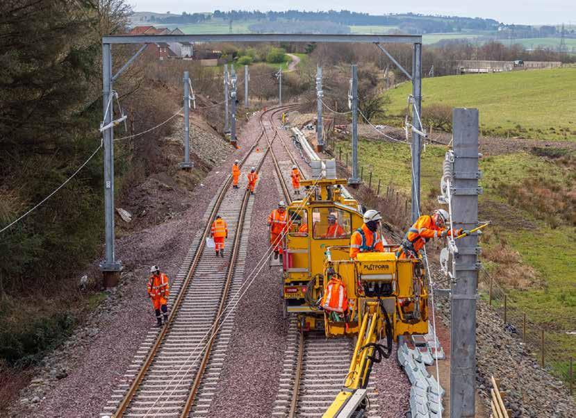
SPL Powerlines UK (SPL) has just completed a major milestone on the East Kilbride Enhancement project as it prepares to enter into service the latest electrified route in Scotland. Regional Director Lee Pounder took some time out to chat with Rail Engineer about the significant achievements following the completion of the recent 16-week blockade of the branch line.
Quiter, cleaner services
The East Kilbride Enhancement project is a £143 million investment at the centre of the Scottish Government’s Rail Services Decarbonisation Action Plan, the strategic roadmap to eliminate greenhouse gas emissions from Scotland’s domestic passenger rail services by 2045.
A significant aim of the project is to electrify the railway line between East Kilbride and Glasgow Central, enabling the introduction of quieter, cleaner electric trains along the corridor.
At just over 7.5 miles, the branch line plays an important role in enabling passengers in the South Lanarkshire region to
reach Glasgow. Diesel units have served the route for decades but from December 2025, electric traction will replace them. Stage 4 of the project involved a 16-week blockade running from 25 Jan to 18 May 2025, during which an ambitious programme of major works was completed. The work included double-tracking 1.4km of railway between East Kilbride and Hairmyres; the installation of over 22km of overhead electric power lines; the erection of new footbridges at Busby, Clarkston, and Giffnock stations; the renewal of the railway bridge over East Kilbride Road in Busby; and lowering the track under four
key bridges. Industry-leading contractor SPL Powerlines led the project, which involved 23 wire runs, 6.8 miles of earth wire, 364 OLE foundations, 98 booms, 22 switches, and 16 surge arrestors.
Originally scheduled to take place in 2020, like a great many plans around that time the programme was interrupted by the Covid pandemic, and during this period, the original plan was reworked.
“The brand new Hairmyres Station is now significant for intermodal use, and it is also particularly vital for patients, staff, and visitors to Hairmyres Hospital, as well as offering travel opportunities for commuters and leisure passengers,” says Lee.
“There have been upgrades along the line of the route at Giffnock and Clarkston, along with a number of new bridges and structures installed to accommodate electrification.

There have been two access for all schemes along the line of route, 50 new signals installed, and three track lowers removing the requirement to dismantle bridges which is a significantly more efficient way to do electrification.”
Seamless coordination
Years in the planning, the programme of works was executed flawlessly with all contractors working together in parallel, minimising disruption to passengers. As a testament to this high level of integration, SPL Powerlines was able to hand back four additional planned weeks of disruptive access.
“We managed to coordinate track, civils, signalling, and electrification, involving six main contractors and multiple sub-contractors, into a defined timeline. Achieving all this hinges on a long, laborious process of closely examining all the contractor activities – the mileages they’ll be working on, the access points they need to use to on-track people and plant, and deconflict the works safely. By planning the works this way it saves significant time and costs seen on programmes that previously relied on planning works sequentially,” Lee says.
“It’s important to acknowledge that we’ve had the benefit of working with some very good project managers, engineers, construction managers, and programme planners on this project, who have been able to
review and interpret all of the project requirements enabling the integration of all of the works.”
Additionally, the successful execution of the programme could not have been achieved without SPL Powerline’s excellent relationships across the industry.
“We benefit from operating in a region with mature relationships,” says Lee. “We operate under what we call the hub and spoke model, where Network Rail is the ‘hub’ and all of the ‘spoke’ contractors sit on the outside of the wheel. All the contractual relationships go back to Network Rail, and we have informal relationships with all the contractors around the outside of the wheel. Those relationships are at the level where we can have very meaningful conversations. We have a genuinely joined-up way of thinking for the greater good of Scotland’s Railway and its passengers.”
Cutting edge techniques
SPL Powerlines’s success has also been aided by innovative ways of working and the employment of some quite revolutionary technology.
For instance, the majority of OLE masts were prefabricated at its compound, Robslee Drive, and delivered to the site already assembled. This way of working, says Lee, brought many benefits.
“Staff are working safely in a much more controlled environment, with the added benefit of reducing the need for people to be going on the track at night. On the back of that, we get a much better product. When we have people working in a yard similar to a factory, the production line methodology improves quality significantly reducing the need for reworks out on site. Ultimately, that means we become more efficient.
“Given the current cost challenges, these maximal gains are really driving the single track kilometre (STK) rate here in Scotland, so much so that the efficiencies that we’re achieving are now commonly talked about in the industry.”
When it came to wiring, SPL Powerlines used its Zeck wiring unit which enables the contact and catenary wires to be installed at full tension on site. The Zeck wiring unit boasts an automatic wire tensioning system and a control panel with a touch screen display, making it easy to operate and ensuring precise wire installation.
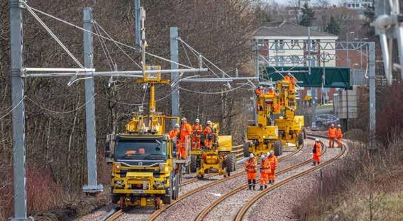
Additionally, the unit is designed to minimise environmental impact and reduce noise levels and carbon emissions.
“I believe it’s one of only two units currently in the UK. It’s been successfully used in England over several years, however this is only the second time it’s been used in Scotland,” says Lee. “It’s been a significant and worthwhile investment for SPL Powerlines which enhances our technical expertise.”
With work on the East Kilbride project underway 24/7 over 16 weeks, the safety and wellbeing of the workforce was at the forefront of SPL’s mind, and the firm employed new technology and innovative strategies to keep workers safe, healthy and happy.
“One of the major innovations was the use of Tended’s geofencing and geotagging system,” says Lee. “We had a geofence around our whole work site, and had all the significant assets tagged including point, marker boards, as well as our compound limits. All our safetycritical staff were geo-tagged as were our plant and engineering trains, so we knew exactly where they were at any given time.
“If you speak to any of our engineering supervisors, they’ll confess it has totally changed the game. They no longer had to go outside to find out what was happening or make endless calls – instead they had a large monitor in front them showing the whole worksite, and the location of engineering trains, plant and workgroups in real time.
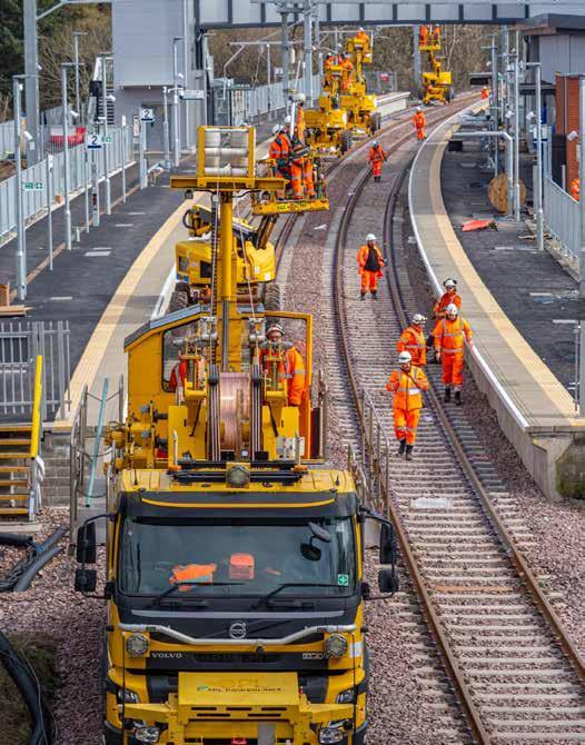
“The technology massively reduced the risk of anybody being in the wrong place at the wrong time. Anyone walking into an area that was out of bounds was immediately alerted by their alarm. It was a game changer and I’m not sure the technology has ever been deployed on a similar scale – it was an incredibly successful deployment of digital innovation” says Lee.
“With regard to health and wellbeing, 16 weeks is a significant amount of time and, as we were working around the clock, we ensured that regular breaks were scheduled,” Lee adds. “We also used that time as an opportunity to monitor staff fatigue. All the contractors went above and beyond in this respect. We ran a health and safety campaign throughout the blockade which saw multiple organisations come along and offer various health checks, both physical and mental. Again, credit is due to all the contractors who were involved in that – it was all very well received by the entire workforce.”
Undoubtably, the latest phase of the East Kilbride project has been a major triumph, but SPL Powerlines is certainly not sitting on its laurels. This is just one key milestone and several more remain, including the reopening of the upgraded East Kilbride station this summer, and the introduction of electric trains at the end of the year.
“While we have broken the back of the construction work, the actual testing, integration works, and final checks and balances you see in any major electrification work all still need to take place,” says Lee. “We need to ensure that when we fully energise the line of route, it’s done in a safe and controlled manner. The end of this blockade means that we are bang on programme, but there’s still a lot of work to do and we can’t afford to be complacent.”
Given SPL Powerline’s success during this latest blockade, this is unlikely to be the case.


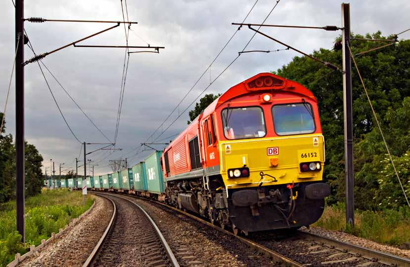
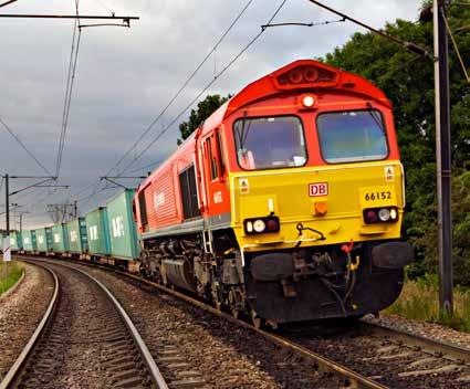
Over the past 20 years the railway has adopted many new technologies on modern passenger trains and infrastructure equipment which have provided significant benefits. However, rail freight has seen little new technology. Most freight trains are hauled by a diesel locomotive introduced in the 1990s. Freight wagons, with no electrical supply, have a maximum speed of 75mph, the speed of the original freightliners when they were introduced in the 1960s. Freight trains are also governed by an operating regime which is little changed since British Rail days.
Though there is an active rail freight research and innovation programme, there are significant opportunities to transform the rail freight sector. To learn more about the potential for such a transformation, Rail Engineer was glad of the opportunity to speak to Karl Watts who led
the introduction of the tri-mode Class 93 locomotive when he was chief executive of the Rail Operations Group.
In his current role as founder and managing director of Railmotive, Karl has produced two papers ‘Rail freight - a path to the future’ and ‘Intermodal Rail freight - a vision of the future’ which form the basis of this feature. The latter paper considers an intermodal freight train operation set in 2032 which takes advantage of the latest operational and technical innovations.
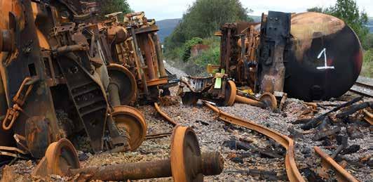
Freight train derailment at Llangennech caused by a wagon’s undetected brake fault.
: 00 CAPTION NOT REQUIRED CREDIT: Network Rail]
Over the past 20 years the railway has adopted many new technologies locomotive introduced in the 1990s. Freight wagons the speed of the original freightliners when they were introduced in the 1960s. Freight trains are also governed by
XM12 in 2032
[IMAGE: 01 CAPTION: Freight train derailment at Llangen Network Rail]
Though there is an active rail freight research and innovation rail freight sector. To learn more about the potential for such a transformation, speak to Karl Watts who led the introduction of the tri -mode Class 93 locomotive when he was chief executive of the Rail Operations Group.
In his current role as founder and managing director of Railmotive future’ and ‘Intermodal Rail freight - a vision of the future’ which form the basis of this feature. intermodal freight train operation set in 2032 which takes advantage of the latest operational and technical innovations.
XM12 is imagined to be an intermodal service from Thames Gateway to Trafford Park which operates in a ‘variable speed’ intermodal path which takes account of a new train classification system. Leaving Thames Gateway, it runs as a Class 6 train to reflect the low speed of the infrastructure. From Wembley, it runs as a Class 4 train to reflect its average speed of 60mph. This gives it a higher priority than Class 5 stopping passenger trains that average 42mph. Along the busy Trent Valley corridor it runs as a Class 3 train to reflect its 90mph maximum speed.
[IMAGE: 02 CAPTION NOT REQUIRED CREDIT: Not applicable]
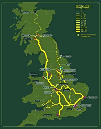
Intermodal rail freight services.
XM12 is imagined to be an intermodal service from Thames Gateway to Trafford Park which operates in a ‘variable speed’ intermodal path which takes account of a new train classification system Leaving Thames Gateway, it runs as a Class 6 train to reflect the low speed of the infrastructure. From Wembley, it runs as a Class 4 train to reflect its average speed of 60mph. This gives it a higher priority than Class 5 stopping passenger trains that average 42mph. Along the busy Trent Valley corridor it runs as a Class 3 train to reflect its 90mph maximum speed
[IMAGE: 03 CAPTION: Intermodal rail freight services CREDIT: As used in Feb 25 feature on Class 99]
of West Coast Main Line (WCML) slow line running times shows the importance of taking account of average train speed. Although its maximum speed is 110mph, the average speed of a stopping train between Tring and Harrow is 42mph. Yet the average speed of an intermodal train is around 60mph. Thus, the Class 4 train should have a higher priority than the Class 2 train. Furthermore, an intermodal train conveying time-sensitive goods worth £20 million could be considered to have more economic value than a lightly loaded passenger train.
By 2032 the rail industry will have a new AI-powered timetabling system to maximise network utilisation and ensure trains are pathed according to their performance. Train prioritisation for timetabling and regulation will also use a value-based system rather than a system that was introduced in the 1950s in which all passenger trains have priority over freight trains. The difference between these two systems is shown in Table 1
[TABLE]
By 2032 the rail industry will have a new AI-powered timetabling system to maximise network utilisation and ensure trains are pathed according to their performance. Train prioritisation for timetabling and regulation will also use a value-based system rather than a system that was introduced in the 1950s in which all passenger trains have priority over freight trains. The difference between these two systems is shown in Table 1.
Class 2025
XM14 is hauled by a high-powered electric or multimodal locomotive as by this time almost all diesel freight locomotives will have been
2032
1 Express passenger train Passenger, ECS, or parcels over 100mph average speed
2 Ordinary passenger train Passenger, ECS, or parcels over 75mph average speed
3 Specially authorised freight train Parcels train Freight train over 75mph average speed
4 75mph freight train Passenger, ECS, or parcels over 60mph average speed
5 Empty coaching stock (ECS) Freight train over 60mph average speed
6 60mph freight train Passenger, ECS or parcels over 40mph average speed
7 45mph freight train Freight train over 40mph average speed
8 35mph freight train Slow freight or engineering train
9 Class 373 train Exceptional service e.g., test train
0 Light locomotive Light locomotive
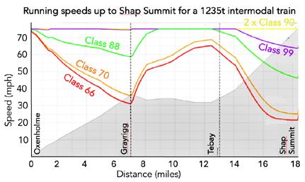
Speed distance graph of different locomotives hauling an intermodal train up Shap summit.
withdrawn. The container flats are 90mph, light weight, articulated, single axle wagons with independently controlled wheels which provide a self-steering vehicle. The wagons can also double the train’s traction power for short periods when accelerating or climbing gradients as each wagon has its own motor powered by a battery which is charged when it brakes.
With such high performance, XM12 can make three end-to-end trips between Thames Gateway and Trafford Park each day running for 19 hours a day – a 90% increase in the train utilisation levels in 2025.
XM12 is operated by the fictitious company Transmodal which is a global freight logistics company specialising in multi-mode freight transport. Rather than trade directly with freight companies, it trades with a logistic company offering a ‘port-to-door’ solution which maximises rail traffic and uses road transport for last-mile deliveries.
Although Railmotive’s vision is for a transformed intermodal freight operation, much of it relates to other freight train operations. The remainder of this feature considers current technology and developments which could deliver this vision.
Despite a large proportion of the core freight network being electrified, in Britain a mere 2.8% of rail freight traction energy consumption is from electricity. Hence few freight trains benefit from electric traction. As electric locomotives have typically twice the power of a diesel locomotive (electric Class 92 - 5MW, diesel Class 66 - 2.2 MW), they can haul heavier, faster trains.
As shown in the graph, a Class 66 diesel locomotive with a 1,235-tonne intermodal train slows from 60mph to 20mph as it climbs the fivemile 1 in 70 gradient to Shap summit, whereas 2 x electric Class 90 locomotives remain at their maximum speed of 75mph throughout this climb.
This illustrates the benefit of electric freight traction on the steeply graded lines between Lancaster and Glasgow.
However, it is not just the northern fells for which diesel freight is problematic. On the gentle 1 in 300 climb between Willesden and Tring, a Class 66 hauled intermodal freight can manage typically 45mph. This compares with 75mph for an electrically hauled freight which is a higher average speed than the stopping trains which enables electrically hauled freight to precede such trains without delaying them.
Although electric freight currently has higher fuel costs than diesel freight, Karl considers this additional cost is far outweighed by the savings from improved asset utilisation and reduced train crew cost that faster electric freights provide. Moreover, faster electric freight trains offer better use of the network as a slow diesel freight takes up two train paths. Surprisingly, the track access regime does not incentivise the provision of extra paths through the use of electric traction.
One reason for the lack of electrically hauled freight in the UK is the need for infill electrification on freight routes to provide electric haulage for the complete route.
The provision of an all-electric WCML freight service would require power supply upgrades. However, the total power capacity these provide could be minimised by intelligent OLE Supervisory Control and Data Acquisition (SCADA) which, for short periods, could automatically reduce peak locomotive traction demand when there are multiple electric trains in the same section.

On 15 January 2021, Rail Operations (UK) Limited signed a framework agreement with Stadler for the supply of 30 Class 93 tri-mode locomotives. The first of these arrived in the UK in 2023. Ride and static evaluations have now been completed and, after successfully completing initial tests with 400 tonne loads over Shap summit, a 2,000-tonne load test was imminent at the time of writing.
As described in Issue 189 (Mar-Apr 2021), the Class 93 is a tri-mode Bo-Bo locomotive. In electric mode, it can run on 25kV AC overhead lines with a power of 4,000kW. Its Caterpillar C32 engine has a nominal power of 900kW which can be boosted by 400kW for short periods (e.g., while accelerating or going up gradients) by its battery pack when operating on non-electrified lines. Shunting operations can also be powered by the batteries alone.
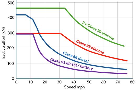
The capabilities of the Class 93 are shown by a comparison of its tractive effort curves with other traction. These curves show how the pulling force of all forms of traction diminishes with speed as power is the product of force and velocity. Diesel traction has a far greater reduction of tractive effort at speed than electric traction. For example, a 2,460kW heavy-haul Class 66 diesel locomotive has a particularly high tractive effort at slow speeds, yet at 40mph it only has 30% of its low-speed pulling power.
In electric mode, the Class 93 has twice the tractive effort of the Class 66 at 75mph. With just a 900kW diesel engine, the Class 93 can manage 60% of a Class 66’s tractive effort at 75mph.
Another new electric locomotive that can operate off the wires is the Class 99 Co-Co locomotive described in Issue 212 (Jan-Feb 2025). Though such locomotives are a solution to the lack of freight infill electrification, the additional costs of such traction over conventional electric locomotives may well be greater than infill electrification. With hundreds of diesel locomotives requiring replacement in the next decade, rail freight companies would no doubt appreciate sight of a longterm electrification strategy.
Railmotive’s intermodal freight paper envisages a train of 12 x three-vehicle articulated sets formed of 10-tonne twin-axle platforms carrying 40-foot,
31-tonne containers at 90mph. Traditionally, such wagons have a 60-tonne payload but in practice the maximum weight of a container on rail is that of the maximum that can be carried on an HGV, which is 31-tonnes. As the wagons are designed for this lower payload they can have single axle suspension, which eliminates the need for bogies and so offers significant weight savings.
It is also envisaged that these wagons would have intelligent on-board systems including wheel flat prevention, brake monitoring, vibration sensors, condition monitoring, GPS, and data transmission like those on the iWagon as reported in Issue 206 (Jan-Feb 2024). However, rather than being powered from axle generator, these intermodal wagons would be powered from the locomotive jumper via a cable throughout the train. As intermodal trains operate in fixed formations, coupling each wagon’s cables together is a more appropriate solution than axle generators.
On the European mainland, it is proposed to introduce Digital Automatic Coupling (DAC) by 2030 for the provision of intelligent wagons and more efficient coupling of freight trains. However, an RSSB report (T1264) estimates that fitting DAC to around 14,000
wagons in the UK would cost £600 million. It concludes that autocoupling offers little benefit as ‘block trains’ are the norm in the UK and that DAC’s main benefit is providing wagons with an electrical supply for which there are more cost-effective solutions.
Railmotive also envisages that wagons will use the ActiWheel system which is being developed by SET. This independently controls each wheel to provide a self-steering vehicle which significantly reduces track forces. This system monitors wheel distance from the track centre then calculates the speed of each wheel for the train to remain centred. It has a permanent magnet synchronous traction motor within the monobloc wheel so does not need a transmission system. Furthermore, as its electric braking works down to zero speed, it does not require friction braking.
This system was successfully demonstrated on a Class 230 unit in 2019. However, introducing such a new radical arrangement will require a robust safety case.
A significant potential benefit of the ActiWheel system is that it could more than double a freight train’s traction power for short periods of time when climbing steep gradients or accelerating.
Freight locomotive tractive effort curves.
This could be done by powering the ActiWheel motors by batteries which are charged when the train brakes.
The Railmotive paper considers how the fictitious global freight and logistics transport company Transmodal offers multi-mode freight transport by trading with a logistics company which is not rail specific as its model considers all container transportation modes to deliver ‘port-to-door’ at any one moment in time. Nevertheless, this is expected to ensure that every train will convey a minimum of 90% payload. Furthermore, this is likely to facilitate the operation of services from ports and terminals with currently unviable low container volumes. This type of operation is that used by iPort Rail. As reported in Issue 201 (Mar-Apr 2023), a Railway Industry Association (RIA) Unlocking Innovation event in Doncaster focused on rail freight and included a visit to iPort Rail which was opened in 2018. As explained at this event, the challenge is to bring
transport elements together for road hauliers to shift their operations from long haul to final mile. For them, using rail freight for long haul with a few short HGV journeys per day is more profitable than long haul HGV operations.
To do this, iPort Rail is working with third party logistics provider Eco2loco to fill the space on its trains and has developed RAILX container booking system to do this. This enables customers to instantly book a container on a train as trainline does for passengers.
Around a fifth of freight train movements are Very ShortTerm Plan (VSTP) movements. Finding the paths for such moves is a cumbersome process as the required data is in various documents that are not well integrated. This is dependant on the experience and skills of planners and has long lead-times making it more difficult for the freight industry to compete with a more dynamic road freight industry. To address this problem, University of Hull’s Logistics Institute has developed NR+ which digitises various documents such as Sectional Appendix, Load Books, RT3973 library, and engineering access statements into a single efficient graphic database. In essence this provides a ‘Google Maps’ for freight train planning.
The University of Hull’s Logistics Institute has also developed the Rail freight Energy and Emissions Calculator (REEC) which uses data from its NR+ system together with other information such as gradient profiles to assess the duration, energy consumption, and emissions of individual freight train moves. It does so by breaking the route into 10 metre segments to which an algorithm is applied. This is based on theoretical equations which have been adjusted and validated using On Train Monitoring Recorder data from hundreds of journeys.
NR+ and REEC are now managed by the University of Hull’s subsidiary Lampada Digital Solutions which, in 2023, won a Network Rail tender to develop the Digital Freight Train Loads book which now has 600 active users.
Much of RSSB’s freight research supports Railmotive’s vision for 2032. Examples of this are:
» Impact of Heavy Axle Weight on infrastructure (Report T1265). In partnership with the University of Southampton, a model was developed to assess future route options for heavy axle weight rail freight traffic on the network.
» Revision W10 and W12 freight gauges (T1327). These gauges were not suitable for some wagon-container combinations for which costly and time-consuming analysis of individual freight vehicles were needed to assess the safe use of new containers on specific trains. This result increased the allowable wagon and container combinations that can run on W10 and W12 cleared routes such as those possible with lower wagons that the ActiWheel system makes possible.
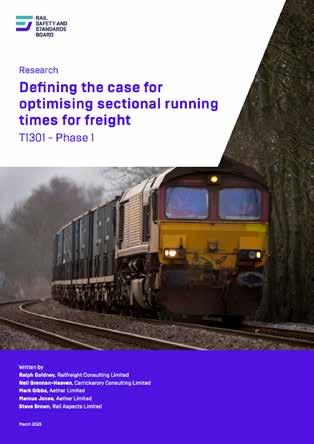
» Optimising freight sectional running times (T1301). This project provided more accurate definition of the maximum trailing load for a freight train by considering a locomotive’s available power and the train’s resistive forces. In all cases studied, it was found that sectional running times (SRT) were too conservative and that heavier freight trains could be run.
» Coupler strength limitations of freight train loads (T1256). The allowable loads for different types of couplers were specified by British Rail in 1969. This research re-examined the engineering principles behind Network Rail’s coupler ‘traction rating’
designation used to set the loading limits and found that they could be re-calculated to allow up to an extra four wagons per train.
» Efficient freight train regulation (T1263). This report was completed in March 2023 and quantified the impact of the current regulation regime, noting that no account is taken of the energy or environmental impact of stopping freight trains. It also produced a good practice guide for timetable development which showed that there was significant potential for improved regulation to reduce freight train journey times.
In 2023, rail freight carried 16 billion tonnekilometres of freight which is 10% of UK domestic freight. In its recent report, Rail Partners considered that this contributes £2.45 billion to the UK economy each year. Furthermore, as well as producing 76% less CO2 per tonne than road haulage, rail freight’s societal costs which include congestion, noise, and accidents are a fraction of those of road haulage.
Yet these benefits are not captured in freight pricing. The Rail Partners report shows that rail freight’s energy and track access / road levies charges are respectively 22% and 113% higher than road haulage.
In December 2023, the previous government set a rail freight growth target of 75% by 2050 which is 2.3% per annum. Given rail freight’s higher costs and network capacity constraints, this is a challenging target. However, as this feature shows, with modern technology, electric traction, and freight-friendly operating practices, it should be possible to achieve and exceed this target, with trains such as XM12 offering an even more efficient service.
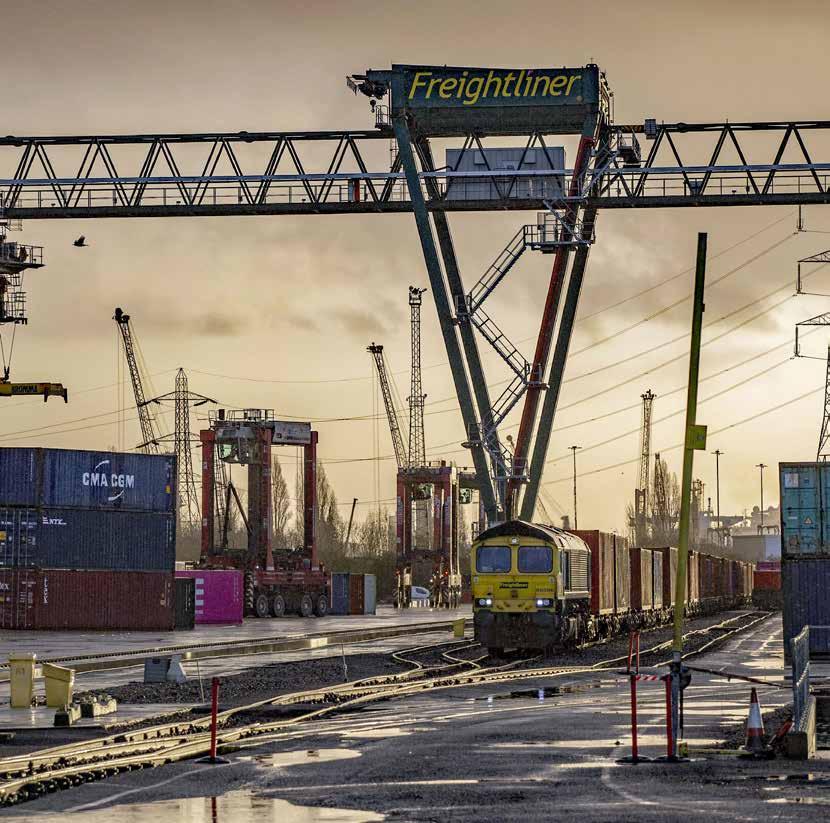
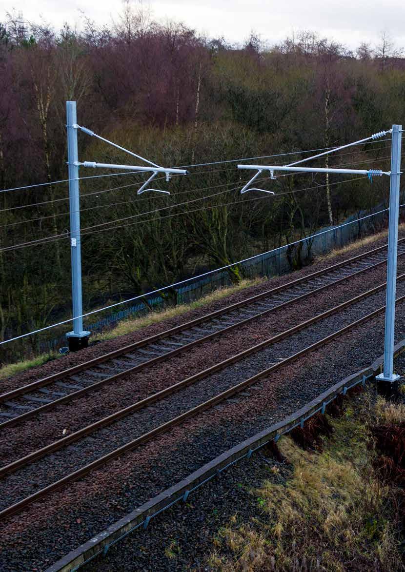
Much of the debate about electrification has tended to centre on operations on routes primarily focused on passenger services, with most of the political comment relating to that.
This is a welcome situation in terms of political support but the railway system in the UK was initially developed for freight and more particular goods, and until the 1960s that traffic was a major portion of the railway income. However, while the Beeching report and associated studies concentrated on passenger services and the impact on personal travel in local communities, a major impact was inflicted on freight traffic and the associated business and facilities.
As the railway infrastructure retreated, freight feeders were severed and the wagon flow that fed the newly developed large marshalling yards in parallel withered away. Allied to that, the view of the government at the time was that a substantial percentage of the railway business could transfer its traffic to the rapidly expanding road system being developed by taxpayers. The net result was that Doctor Beeching effectively killed off much of the railway goods traffic. However, he also proposed the concept of Freightliner container services, to this day a major component of freight movement on rail.
As the debate on the extension of main line traction system installation develops, we now find ourselves needing to view route electrification in relation to freight operations.


The most important message is to keep it low cost, keep it focussed on freight traffic, and tackle it incrementally. Short infills are good, we must avoid the temptation to grow proposals into huge multifunctional projects.
In line with current environmental thinking and government leadership, the impact of transport on the environment is a high-profile issue. Net zero has to be examined across all industries and the whole economy in which, tonne-fortonne, moved rail yields the least greenhouse gas and pollution when compared to other transport modes.
As mentioned, British Railways modernised mineral traffic and introduced containerisation but placed passenger services first and foremost. However, rail in total has a potentially significant role in delivering net zero across all industries and the whole economy by maximising the modal shift of container trunk traffic from road to rail.
To set the debate, there is a societal issue related to UK history, where more than two generations have passed since the British Railways era passenger-centric view came into being. Changing that culture will be challenging work.
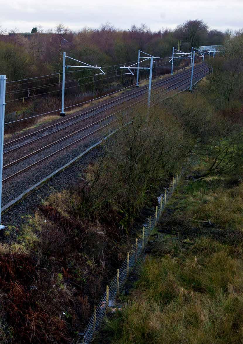
Peter Dearman, past president of the Permanent Way Institution and senior visiting lecturer at Sheffield Hallam University, argues for two objectives on behalf of the industry:
» One: immediately prioritise freight infill wiring short sections and routes where those infill works will increase electric haulage of existing freight. Some container trunk routes are today operated by diesel traction along 100% of their journey for want of a few miles of missing wire.
» Two: immediately gauge clear the container traffic routes from the East Coast Ports to allow freight industry colleagues to substantially increase the trunk route container traffic between the ports and the distribution hubs. These routes have been clearly identified by the freight operators. Peter argues that the earliest possible completion of these gauge clearance works will provoke a large-scale modal shift to rail. Even with diesel operation, the carbon benefits will be substantial. Later, against the background of much increased traffic, and in later stages of the investments to green the economy, the case for electrification will then be easier to justify.
Ultimately, Peter strongly believes that there must be a rebalancing of the main line rail industry culture which prioritises passenger traffic. This is imperative if the railway is to fully deliver its potential in the greening of the economy as a whole.
Overall, freight electrification should be at minimum cost. The industry needs a new willingness to apply frugality.
In terms of that frugality, 75mph is fast enough and there is no need to build 100mph Overhead Contact systems for freight. Similarly, the traction power works should be sensibly engineered, 25-0-25 feeding being used to minimise the number of supply points and maintain voltage at the pantograph.
Advantage must be taken of new traction unit development, and the capability of Class 93 trimode locomotives can allow short dead sections of discontinuous electrification, which should be leveraged.
Such developments as the Furrer and Frey moveable overhead contact system, demonstrated at Wellingborough recently, illustrate the commitment of electrification designers and constructors to bring forward novel power and contact system hardware suited to the freight business.
There are considerable opportunities to add infill schemes to current main line electrified routes at minimum cost with a surprisingly high impact. Thus, a long-distance haul without change of traction becomes distinctly viable.
Having reviewed the environment in which infill electrification may extend and flourish, it is worth a study of where improvements in the traction connectivity might be applied. Presentations at industry events have often referred to the difference in connectivity between UK nations and several examples exist of freight terminals being connected to the electrified network in Scotland but not in England at the other end of a traffic flow. Thus, a flow may well be diesel-hauled for a distance under the wires.
Some major examples of significant terminals which are not connected to the electrical traction systems include the not insignificant ports of Felixstowe and the more recent development of Thames Gateway in Essex; adjacent to the channel tunnel high-speed one link. The latter has been the subject of a study in the provision of contact system equipment at an economical price.
Another east Coast port not connected is Hull, with the approaching route also not wired! The lack of electrification connectivity is not limited to traditional coastal ports, and a major example is that of Doncaster freight terminal. The Scottish end of the conundrum is not without relevance with connection needed at Motherwell.
The Transpennine Route Upgrade is a major scheme with significant potential gains for freight but, even there, access for freight is not total. At present, access to Trafford Park is not available to electrified traction although it must be noted that the proposals in connection with the football ground may lead to a new terminal developmenthopefully connected as new!
Perhaps of a greater scale, but with potential gains in relieving current routes, would be an electrified route into Manchester? A similar major connection would be Leeds, Harrogate, and York to link up two electrified routes.
Mention was made earlier of the Furrer and Frey retractable OLE, recently demonstrated at Wellingborough (though not currently wired),
which could allow the economical wiring of ‘Normal’ sidings and allow the handling of containers away from major sites; again, to be connected to electrified routes.
Recent developments in bi- and tri- mode locomotives have been interesting in terms of ‘last mile’ traction off the wires but these may not be a solution for the type of major freight flow traffic that is really needed as part of the move to net zero, albeit there may still be ‘spot development’ of special flows which may be of short duration.
Grasp the opportunity
There has been discussion of freightfocused electrification infills since the IMechE Professional conferences earlier in the century.
The opportunity to make real growth in long distance freight haulage is still there for relatively minimal wiring and power feeding of short routes off the existing electrified mainlines. That opportunity is here without huge investment and the industry is ready to move.
While we have concentrated on freight infills, it is impossible to ignore the mainlines still not electrified with their relevance to passenger, freight, and parcels traffic. Full electrification of the Midland Main Line and Great Western Oxford and Bath spring to mind with heavy aggregate flows, and one could dream of bringing the stone out of Derbyshire with electric traction. As a finale can we remember the ‘Electric Spine’, now buried in history, which could have brought electrified freight all the way from the south coast to the east coast mainline.
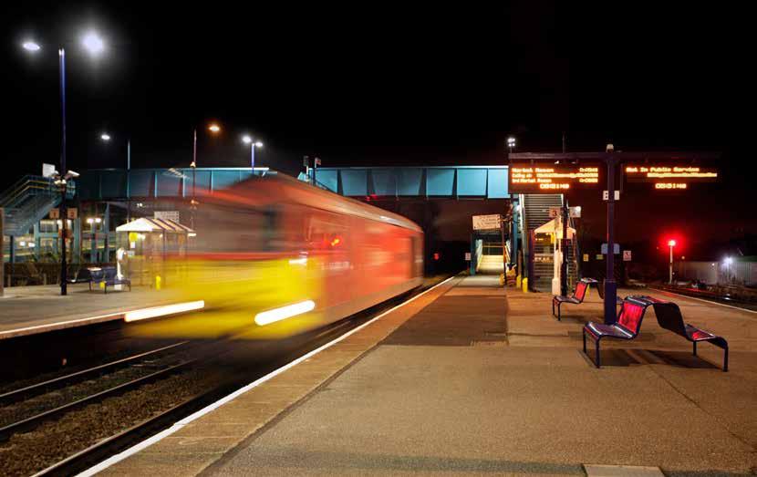
This article is inspired by conversations with Peter Dearman and other industry colleagues and provides their personal but informed views of how freight flows with electric traction could be brought into use. Here’s hoping the country show the will to proceed.






Connecting the UK rail industry for over 28 years.


In 2011, Sir Roy McNulty’s rail value for money studyRealising the potential of rail in Great Britain - concluded that GB rail cost £3 billion per annum more than it should and that a 30% reduction in cost per passenger-kilometre should be achievable.
It found that these high costs were due to the fragmentation and misaligned incentives. It also considered that “the history of innovation in the GB rail industry has often not been impressive” and recommended the creation of a leadership group to drive innovation which was felt could deliver 18% of the required savings. Unfortunately, as shown by the table, UK rail’s cost to the taxpayer per passengerkilometre has increased by 92% since 2009/10. Though UK rail has failed to keep its costs down, many new technologies have been introduced since the McNulty report. Hence, this feature looks back to consider whether it is still the case that UK rail has an unimpressive innovation record.
included the Transport Strategy Board (TSB) in 2007; Rail Research UK Association –universities working in with industry (2011); and RSSB’s cross industry Enabling

RIA’s Innovation Conferences
RIA held its first Innovation Conference in 2009. This was a one-day seminar for around 50 delegates. At that time only 18% of the mobile phones sold in the UK were smartphones and innovation was rarely talked about within the rail industry. Your writer attended his first RIA Innovation Conference, which welcomed 177 delegates, in 2013. Much of this conference explained the role of organisations that had recently been established to promote innovation. These

Innovation Team (2012). In 2011, Network Rail launched its new approach to innovation which included challenge statements to advise the supply chain of the problems it faced. 2012 saw the launch of the Rail Technical Strategy as well as RIA’s Unlocking Innovation programme.
The TSB, which became Innovate UK in 2014, launched its first Accelerating Innovation in Rail competition in 2011. Another of its initiatives was Knowledge Transfer Partnerships to help businesses
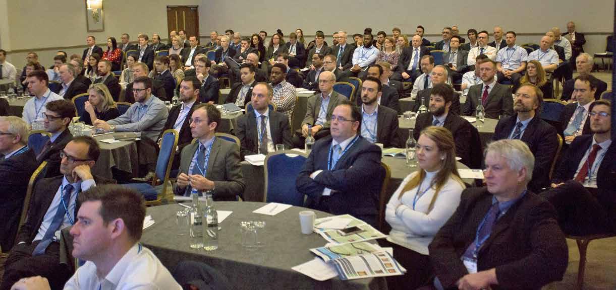
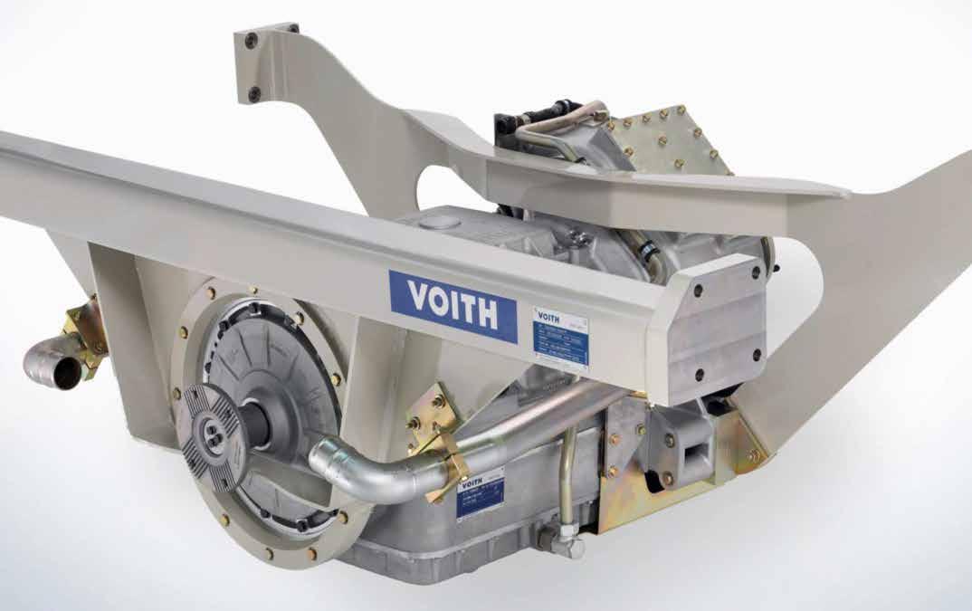
develop new products with the help of an expert academic adviser. Also, in 2013, the Department for Transport required new franchises to include R&D spend. Thus, although the overall rail industry innovation leadership group that McNulty had proposed was not established, various organisations had been set up to promote innovation. However, potential innovators did not have a clear route to progress their ideas, though RIA did much to clarify the roles of these organisations. RIA’s conferences have also showed the difficulties of implementing innovations. The 2017 conference revealed arguments about ownership of the data from the trainmounted energy harvesting sensors which could benefit both the train operator and Network Rail. In 2018, it was shown that train operators with short franchises cannot find a business case for DMU gearboxes offering 16% fuel savings.
These conferences always had thoughtprovoking keynote presentations. In 2017, it was explained how cloud computing and smartphones provide mobility as a service by integrating all Helsinki’s public transport. This significantly increased the use of public transport which is paid for by a monthly subscription. In 2018, a Siemens presentation showed how improvements in remote condition monitoring were the key to reducing cost of offshore wind power from £200 to £52 per MW/hr.
The 2025 conference
RIA recently held its sixteenth innovation conference in Newport, South Wales. The event was attended by almost 500 delegates and had 61 exhibition stalls. Away from the conference hall, there were exhibition spotlights at 19 of these stalls. At pitch sessions, innovators presented their ideas to innovation managers from train operating companies. A hackathon also offered the opportunity to showcase their digital innovations using data from the Rail Data Marketplace (RDM) to tackle defined industry challenges.
In the conference hall there were keynote presentations, ‘fireside’ chats, technical talks and panel discussions. As always it was a worthwhile thoughtprovoking event.
Many of the speakers were from organisations supporting innovation.
Geoff Ogden, chief transport planning and development officer for Transport for Wales (TfW), explained his organisation’s innovation accelerator programme which, this year, will focus on revenue generation and cost efficiency, modal shift and engagement, as well as operational excellence.
Dr Alan Peters of Connected Places Catapult (CPC) explained how CPC’s
refreshed strategy applies effective procurement routes, fosters a culture of innovation, and promotes data sharing infrastructure and international collaboration.
Paul Corcoran of the Rail Supply Group (RSG) explained the purpose of the rail sector’s innovation charter which includes clear commitments related to procurement and bidding, supply chain collaboration, data sharing, and intellectual property ownership. He emphasised the importance of behaviours and advised that those in the industry should not wait until rail reform to change its behaviours.
Since 2017, Innovate UK has run seven First of a Kind (FOAK) competitions which awarded 128 companies innovation funding for specific themes. Klara Ludinova described the eighth FOAK completion in which organisations can apply for a share of up to £4.7 million across four themes of Platform Train Interface, Personal Safety, Bridge Strikes, and AI for complex processes. The successful companies have to develop a prototype, conduct field testing, and demonstrate their solution. Projects can last between three and seven months and must be completed by March 2026.

UKKRIN panel discussion.
Gareth Evans describes RD&I partnerships at Network Rail worshop.
The UK Rail Research and Innovation Network (UKRRIN) was established in 2018 to create a collaboration between academia and industry, with centres of excellence in rolling stock, infrastructure, digital systems, and testing. In a panel discussion Professor Paul Plummer of the University of Birmingham (digital systems), Professor Paul Allen of the University of Huddersfield (rolling stock) and Rod Anderson from the University of Southampton (infrastructure) reflected on UKRRIN’s successes. Paul Allen made the point that the industry should make best use of UKRRIN’s high-cost facilities such as the rolling stock rigs at Huddersfield.
Simon Jones, the chief executive of the Global Centre for Rail Excellence (GCRE), described how GCRE had recently showcased 12 projects through a £7.4 million ‘Innovation in Railway Construction’ competition as described elsewhere in this issue.
As reported in Issue 210 (Sept-Oct 2024) GCRE has plans to construct two 7km loops on top of a Welsh hill, one to test rolling stock and one to test infrastructure. Seventy million pounds of Welsh and UK government funding has been used to establish this project. GCRE is now in discussions with a potential funder for the hundreds of millions needed
to complete this facility which 200 companies across the international supply chain have expressed their desire to use.
Network Rail’s RD&I
Network Rail Chief Technology Officer Robert Ampomah described how Network Rail aims to use innovation to meet its key priorities of: cost efficiency, boots off ballast, use of data, and weather resilience. He advised that Network Rail wished to grow innovation partnerships and was committed to RSG’s innovation charter to attract and support SMEs.
On day two, Martin Taylor, Network Rail’s Wales and Western infrastructure director, told delegates that his region has £4 million available for research and development.
He wished to see this used to create digitally enabled teams and encourage innovations that deliver the outcomes our customers desire. He illustrated his presentation with examples of innovations which included optimised earthing, the PodFlo possession safety critical communication app; climate adaptation pathways, and drones.
Network Rail’s ‘Unlocking RD&I’ workshop had presentations on funding, procurement, and partnerships. Head of Strategy James Heslop advised that Network Rail’s CP7 funding settlement included £146 million for RD&I from which it is expected that cross-industry collaboration will raise an additional £70 million of co-funding. He explained that good RD&I proposals must be aligned with the railway technical strategy, have a benefits case endorsed at route level, consider commercially off the shelf solutions and have a procurement case. He advised that Network Rail’s RD&I programmes typically offer a benefit cost ratio of 2.5 and rarely fail.
Sourcing Manager Adam Titmus explained the implications of the 2023 Procurement Act in respect of prototypes and development. He considered that this encouraged innovation and simplified the bidding process by, for example, auditing

accounts after award. Head of Rail Technology Gareth Evans described how partnership funding potential is identified for each Network Rail challenge statement.
In addition to its UK funding partners such as Innovate UK, UKRRIN, and the Manufacturing Technology Centre, Network Rail has an International Research & Development partnership programme. This includes collaborations with ProRail (Netherlands), BaneNor (Norway), Trafikverket (Sweden), the Korean Rail Research Institute SBB (Switzerland), and Canada’s national railways.
Passengers and freight
Shamit Gaiger is managing director at the West Coast Partnership development which is to introduce HS2 services. She advised that customers were the heart of its decision making and how innovation was embedded into the company’s thinking. However, it is difficult to see how innovations can overcome the severe capacity constraints from the decision to cancel HS2 Phase 2a. Speaking to Rail Engineer after her presentation Shamit advised that there were plans to address this issue which will be revealed in due course.
LNER Managing Director David Horne, described its annual accelerator programme, FutureLabs, and the company’s recent innovations. These included seat sensors to identify unoccupied seats and at-seat QR codes for at-seat ordering. He advised that LNER was to remove Off-Peak fares and introduce a new non-refundable 70-minute flex fare that can be used within 70 minutes of the booked departure time.
From Avanti West Coast, Managing Director Andy Mellors stressed that the pandemic requires the industry to be more agile and that it is more important than ever to work together. In this respect he mentioned Avanti’s Superfare tickets for which customers are given 24-hour’s notice of their train having booked a morning, afternoon, or evening departure slot, 56 to seven days beforehand. Avanti is also collaborating with RSSB on a social value programme
which had an impact of £212 million per year by initiatives such as its Feel Good Field Trips programme that 8,000 children have so far experienced.
Richard Thorp is chief operating officer of London St Pancras High Speed, formerly HS1. His presentation explained that although there is a huge demand for international rail travel, St Pancras station is currently a huge constraint. Furthermore, as the HS1 route is now over 15 years old, renewal volumes are increasing exponentially. Hence the company’s challenges for its CP4 are automated inspections, predictive maintenance, optimised planning, and better use of data. He considered that as it is difficult to change how people work, it is important to think beyond the technology to the people who will be using it.
RIA also launched its report ‘The Journey to Equality: creating a railway for all’ which showed what needs to be
done to improve accessibility across the railway network. This highlights the challenges faced by disabled people for which readily available solutions are available.
While the modern passenger train has the latest electrical control systems, a freight wagon has no electricity supply at all which makes it difficult to innovate. As reported in Issue 206 (Jan-Feb 2024), the iWagon has an electric supply that enables wagons to have wheel slide protection and provide real-time event data. Sanjay Albert, Knorr-Bremse’s director of engineering and innovation advised that 31 wagons are about to be certified for unrestricted use and that over 1,000 wagons have been targeted for retrofitting.
The 61 stands at the conference showcased numerous innovations. What follows is a necessarily small selection of these new technologies some of which related to conference presentations. For example, the Knorr-Bremse stand had a model iWagon, Arcadis were demonstrating its Enterprise Decision

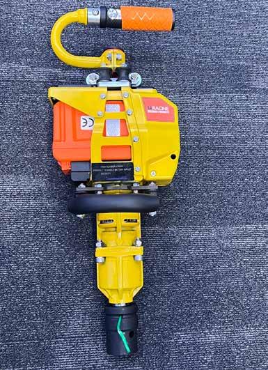
(Above left) Lightweight battery powered impact wrench on Unipart stand. (Above right) Tended wearable positioning alarm.
Analytics which help manage asset decisions, and Telent showed how AI has enhanced automated incident reports from its station management system.
The Transmission Dynamics stand explained how its train-mounted PANDA-V pantograph and overhead line monitoring system can now interact with the Intelligent Pantograph Network to prevent dewirements. It does so by instructing trains to drop their pantographs when approaching significant OLE faults found by a PANDA-V.
Other train mounted infrastructure monitoring systems included those from CrossTech and OneBigCircle. Fugro also has a train-mounted gauging system.
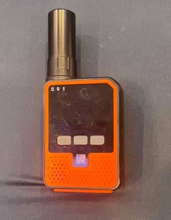
& Western region, offers possession management for the digital age to ensure everyone has access to critical information in real time. Also keeping track workers safe is Tended’s geofencing technology which warns workers if they leave their safe zone. This uses Real Time Kinematics GPS technology which is accurate to centimetres as it is related to the known location of a fixed base station. This system can also be used to monitor the position and speed of vehicles on site.
Another safety related system on display was the COMET incident investigation system which includes human factors analysis to ensure root causes are identified and lessons learnt from them.
One of the most significant announcements at the innovation conference came from Toufic Machnouk, managing director of GBRX, which has been created to deliver one of the core missions of Great British Railways (GBR): driving strategic innovation across
Toufic Machnouk addresses the conference.
For those working on track, Unipart offered lightweight battery powered hand tools designed to minimise hand-arm vibration while PodFlo, which is now in use

track and train and improving how the railway works for people.
In his presentation, Machnouk outlined GBRX’s role in confronting long-standing barriers to technological progress within the rail sector. He emphasised that innovation must be understood not simply as creativity, but as a structured process to solve problems and deliver meaningful improvement.
While the railway has adopted a range of technical innovations over time, Machnouk highlighted that many of its fundamental systems, from mechanical signalling to planning processes, routewide data management, and energy use, have seen little transformational change.
He identified two critical blockers to innovation:
» The complexity of changing working practices within a highly regulated environment.
» The challenge of evolving a vast, tightly engineered industrial asset base across a fragmented commercial structure.
To address these systemic barriers, GBRX is establishing a Portfolio Board to align and oversee innovation resources across the sector. It will also launch an Innovation Platform to give potential suppliers and partners a structured route into the railway system, providing clearer pathways for ideas to be developed, tested, and adopted at scale.
As always, the RIA Innovation Conference was thought provoking with many worthwhile innovations on display. However, it is difficult to assess what is new each year, so it is perhaps more meaningful to consider the innovations introduced since the first RIA Innovation Conference in 2009, as shown in Table 2.
Previous conferences have shown that some of the barriers to innovation that McNulty identified in 2011 have been eased. For example, there has been a significant increase in the use of passenger trains for infrastructure monitoring while, in 2017 there were arguments about who owned the data from such monitoring.
Furthermore, the demise of short passenger train franchises should remove barriers to investment in kit such as gearboxes offering a 20% reduction in fuel consumption, but whether there is sufficient government finance for such profitable investment is questionable. Indeed, it is this, rather than innovation technology, that has been the barrier to the removal of mechanical signalling that Machnouk mentioned in his GBRX presentation, as well as other profitable investments such as rail electrification.
Rail Minister, Lord Peter Hendy’s shares McNulty’s view that the railway has been held back by the slow adoption of innovations. However, as Table 2 shows, since 2009 there have been some impressive innovations. For example, new trains have a quantum leap in technical capabilities and much has been done to automate infrastructure monitoring.
To advise the supply chain of the problems it faced, Network Rail first issued challenge statements in 2011. It spends around £50 million per annum on its RD&I programme which has an estimated return of £3 for every £1 spent and includes many worldwide innovation partnerships. This would seem to be the approach that GBRX is to adopt for the whole industry, in particular the track train-interface which presents particular problems as the implementation of ETCS has shown.
As we reported in Issue 201 (Mar-April 2023), an ORR report on Network Rail’s introduction of new technology shows
Machnouk is right to emphasise that innovation is a process as this report showed that incorporating new technology into existing processes was a significant barrier. Furthermore, there is a need to update planning processes. At the 2017 conference concern was expressed that it would probably take Network Rail six months to advise what is needed to increase the weight of a freight train from 2,000 to 2,600 tonnes. This issue’s rail freight feature indicates that there has been some progress in this respect.
The above indicates that much good use is being made of the latest technologies. Yet, as McNulty recommended 14 years ago, a strategic body is needed to drive innovation across the industry as a whole and co-ordinate the work of existing rail innovation bodies. It is good to see that, as part of the implementation of GBR, the establishment of GBRX belatedly implements this 2011 recommendation. Rail Engineer wishes GBRX well and looks forward to reporting how it will drive innovation across the whole industry.
Table 2.
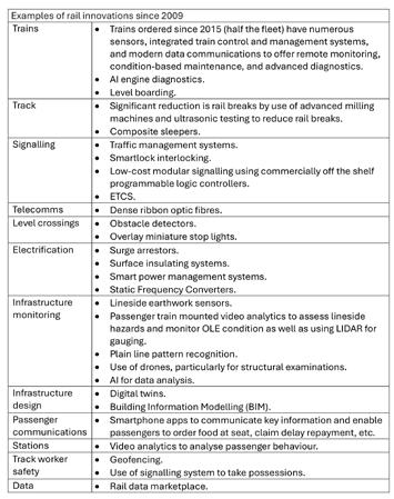
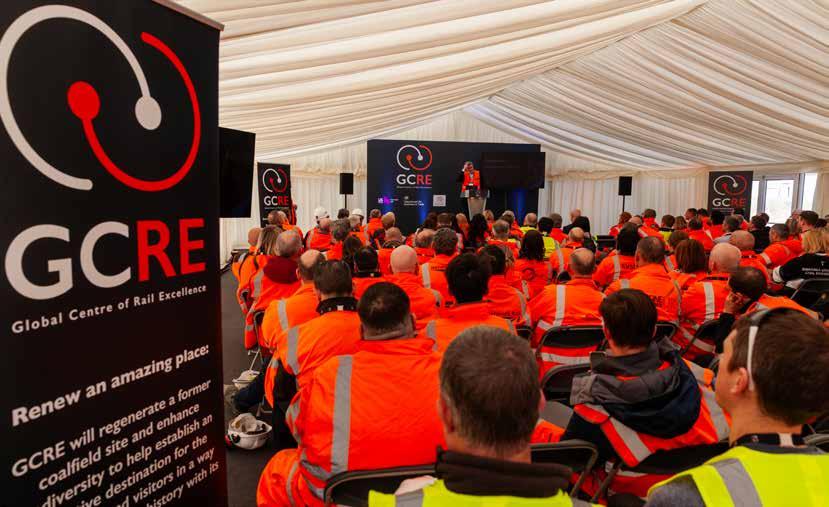


An event in March hosted by Global Centre of Rail Excellence (GCRE) highlighted the projects that have been supported through the Railway Construction programme. The programme competition, which started in 2022, has been funded by the Department for Business and Trade and delivered by Innovate UK, with teams installing their projects at the GCRE site.
GCRE was established in 2021 with a commitment of £50 million from the Welsh Government. The UK Government has provided £20 million and a further £7.4 million is being provided through Innovate UK for Research and Development. The site spans the former Nant Helen opencast site and Onllwyn Washery, and the Neath Port Talbot and Powys local authority area in South Wales.
Subject to raising the required funding, the GCRE facility will include two electrified rail test loops, one a 7km-high speed rolling stock track with a maximum speed of around 177km/h (with potential for 201km/h) and another infrastructure test track. The facilities will include
a dual-platform test environment, rolling stock storage and maintenance facilities, operations room, staff accommodation and connections to the main line. There will also be visitor and conference facilities, a business park and a hotel. At the event, 12 projects took the opportunity to showcase their equipment and technology including self-healing concrete, new drone technology, and more cost-effective forms of electrification and signalling. The demonstrations were established across the extensive GCRE site, with two inside the centre’s offices, seven around the sidings near the main building, and three close to the boundary with Network Rail.

With its Indus system using telecoms fibre cables to remotely sense activities, Focus Sensors has developed multiple fibre sensing use cases to benefit the rail industry. These include enhanced safety, with intruder detection at large sites reducing need and cost of physical barriers and cameras. Additional uses include monitoring embankment slips, geotechnical changes and track stability, ground saturation monitoring, finding water leaks, and detecting wheel impacts.
During the day, Focus Sensors demonstrated accurate detection of intrusion using GCRE’s trackside optical fibres. A pre-defined 8-metre x 2-metre alarm zone was established, and this alarmed only when an intrusion into the area occurred, with no false positive alarms from the 200 visitors and innovators moving and working around the site. Focus Sensors is now trialling the system alongside a working railway on the Anglia route, part of Network Rail’s Eastern region.
Based locally in Central Newport, Wales, Ingram Networks Ltd is developing an ultrafast train communications system to transform passenger Wi-Fi. It says its solution is suitable for all environments (rural and urban), and the technology will improve the customer experience and improve the productivity for those wishing to work during their journey.
Ingram Networks are in active discussions with Transport for Wales, and intend to use the GCRE facility to showcase their solution to other operators both in the UK and worldwide.
Universal Signalling Ltd was founded in 2022 to commercialise intellectual property which has been under development by the founders since 2018. Universal Signalling says its goal is to bring revolution to the worldwide railway signalling market through a blend of technology, operating model, and open interface specification.
Working alongside a number of supporting partners including Birmingham Centre for Railway Research and Education (BCRRE), Universal Signalling are to deploy an overlay of its Universal Interlocking system to the GCRE track and look forward to being part of GCRE’s journey, through the construction phase and into operations.
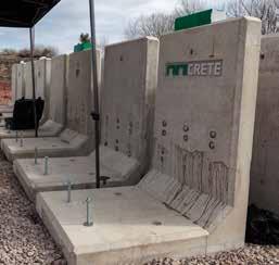
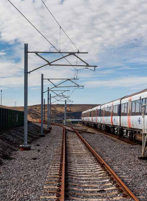
Following the demonstration day, Universal Signalling announced the securing of the first tranche of its pre-seed investment round. This was led by SFC Capital, with additional funding provided by a group of business angels. GCRE said this was a great output from the day and exactly the kind of thing they wanted the projects involved to achieve.
Furrer+Frey AG, a supplier of overhead contact line systems in Switzerland and around the world, had two projects on display at GCRE. The first, called CODES (COst-reducing Dynamic Electrification gradient System), demonstrated a design to allow for the easy adjustment of the height of a catenary. The second was a composite cantilever that is both lighter and less susceptible to corrosion than traditional overhead contact line system cantilevers and called ICAGE (Innovative CAntilever for Greener Electrification).
Mimicrete, based in Cambridge, demonstrated its self-healing concrete for retaining walls. Founded in 2021, Mimicrete is an advanced materials science company, developing self-healing concrete. The technology was developed via a doctorate within the University of Cambridge’s Geotechnical and Environmental
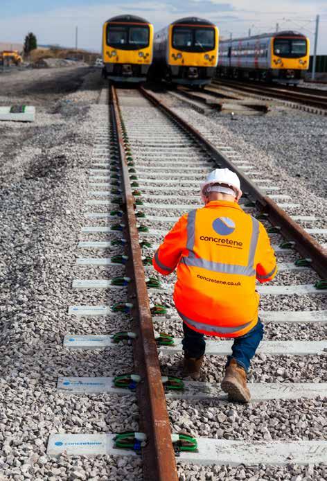
Research Group in the Department of Engineering. The self-healing concrete solution can heal concrete cracks as soon as they open up. This avoids further cracking, subsequent structural issues, and the need for repair and early replacement. It can also both lengthen concrete lifetime and reduce the need for overengineering. Other benefits include reducing the amount of concrete required and the associated carbon emissions, and structural monitoring and maintenance costs.
Concretene is a graphene-enhanced admixture for concrete that delivers savings on cost and CO2 emissions. Over the course of a year, Concretene worked with Cemex Rail to deliver a lower-carbon concrete sleeper and cast 60 sleepers for installation at the GCRE site. These used 3.75kg less cement per sleeper (7% CO2 reduction) and met the testing standards of both Cemex and Network Rail for G44-type sleepers
The sleepers were installed by local contractor KGJ Price and Concretene says its secondgeneration sleeper is already in development and that a 15% reduction in CO2 should be
achievable. It added that very productive discussions had taken place with representatives from DBT, Network Rail, Vossloh, Arup, and others regarding the potential deployment of its sleepers in depots and on the network.
AUS Ltd demonstrated is Composite Twin Track Cantilever (CTTC), which is compatible with both old and new infrastructure. AUS Ltd was founded in 1998 and is located in Clayton West, Huddersfield, West Yorkshire. It manufactures and supplies specialist equipment to the electrical supply, rail, arboriculture, and telecoms industries. AUS Ltd said its CTTC was born from relentless innovation and fruitful collaboration with The University of Huddersfield, which has propelled it to the forefront of railway construction.
Based in Cambridge, RoboK, is a computer vision start-up whose mission is to make industrial workplaces safer and higher performing using AI. It has developed innovative, privacy-preserving, and cost-effective AI technology to make the most of CCTV cameras. To reduce the chance of injury and encourage better behaviour, RoboK’s AI solution can be used to highlight issues of concern. The tool can also be used to determine whether a level crossing of a railway line is being used correctly by members of the public.
Drone Evolution, based in Caerphilly, South Wales, demonstrated the use of tethered drones in rail. Drones have much to offer rail inspection and surveying, but they typically only stay in the air for around 20 minutes before their batteries need to be changed. However, by powering the drone via a tether attached to a ground station the drone can stay in the air for extended periods of time. This also limits some of the risks associated with drones, such as flyaway.
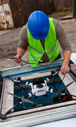
Silicon MicroGravity is a privately held company based in Waterbeach, north of Cambridge. Its objective is to solve complex challenges and create value through the application of gravity and motion detection, by capturing gravitational and motion data at sensitivities not easily or economically achievable with traditional technology. It has identified applications for its platform technology across a large range of areas including inertial navigation for robotics, autonomous vehicles, civil engineering, and security. Its demonstration at GRCE showed what is possible for gravity sensing in rail construction.
EneRail Ltd was originally founded within the University of Birmingham and based at UKRRIN on the University of Birmingham campus. It provides technology and expertise to deliver savings, and decrease carbon emissions associated with power systems through performance improvements. Rail systems use a considerable amount of energy in day-today operations and using the right strategy for controlling the driving of trains can significantly influence energy saving performance. EneRail has developed technology to provide enhanced control strategies for drivers to achieve energyefficient operation. It can model the route and vehicle, calculate the optimal driving control strategy, and present the results to the drivers in smart ways.
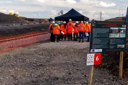
After an excellent day of innovative rail industry engineering demonstrations, Simon Jones, GCRE Ltd chief executive, said: “It has been genuinely fantastic for the GCRE to play host to the Innovation in Railway Construction programme and to see the 12 teams at the demonstration day that have been funded to bring their ideas to life.
“We’ve seen creativity and ingenuity from teams as they have tackled some of the biggest challenges in rail, giving us a glimpse of what a more sustainable and more affordable rail network looks like.
“What has been unique about this programme has been the ability of the teams to take their technology and demonstrate it to a live industry audience, in real time. That has had an impact already as we know there are teams involved in the programme that have already seen new overseas interest and leads, new contracts, and, in some cases, new investment in their companies.
“That’s exactly what we hoped for and it shows the power of what GCRE can do, as a purpose-built site to support technologically advanced rail innovation and, particularly, the commercialisation of new ideas into new business and export opportunities.”


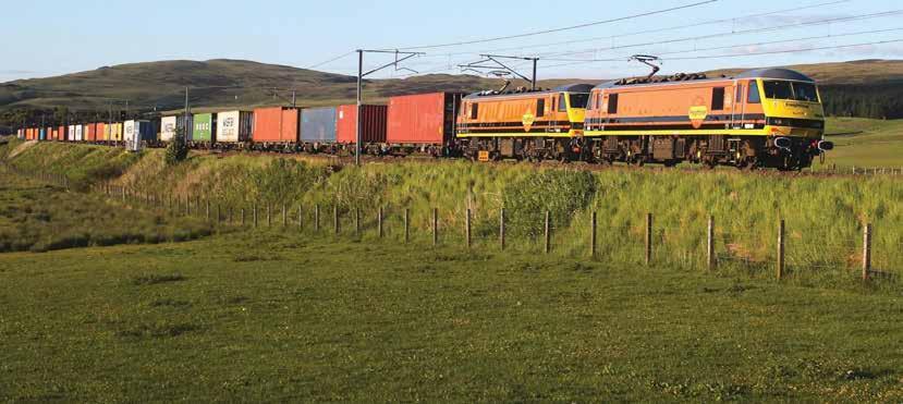
The Institution of Mechanical Engineers Railway Division recently held a railway gauging seminar, attended by 60 delegates. A similar event was previously reported on in Issue 202 (May-June 2023).
Paul Long, Freightliner’s head of traction and rolling stock and a member of the industry Vehicle/Structure System Interface Committee (V/S SIC), gave the freight keynote. He said that bulk/heavy haul using L1 gauge locomotives and W6A gauge wagons are relatively straightforward from a loading gauge perspective. Axle loads are another matter (as discussed later).
Paul gave examples of new opportunities such as hydrogen/ ammonia transport for fuel and carbon dioxide for storage. Intermodal (container) traffic also presents opportunities but there are challenges.
heavier than usual requiring a particular wagon type, and curtain sided containers that present new risks. Furthermore, containers are not necessarily 20 feet or 40 feet long as some users have developed 50-foot containers.
As an example, many of these bio-fuel plants are located where the line has never been gauged for the wagons proposed for the service. A route might have sections cleared for the proposed train, sections that have never been assessed, and sections not clear. That said, Paul thought that progress is being made with the objective of:
RSSB’s completed research project T1327 explored revised W10 and W12 gauges to increase freight access to the GB rail network which offered small gains that Paul said would lead to big opportunities. He concluded with a plea for an easy tool for planning freight routes. The current process of working out what train can run where, and when, involves assessing timetables, wagons and locomotive gauges, weight, and J tables which RSSB defines as: “a set of tables that set out the acceptable combinations of load units and vehicles for freight gauges W6a, W7, W7a, W8, W8a, W9, W9a, W9plus, W10, W10a, and W12”.
(Below) HS2 tunnel segment pallets loaded onto container flat wagons
While containers are generally standardised, all sorts of container loads present interesting challenges. He gave examples of carrying HS2 tunnel sections strapped to container cradles, carrying batteries in containers that are
» Changes to existing profiles and definitions to reflect, for example, that not all container wagons are high deck and 60 feet long.
» Using modern gauging simulations, and
» Applying all gauges everywhere
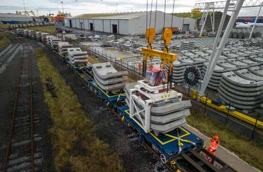
Paul likened the process to wartime decryption at Bletchley Park. The task can take 10 person-days over two months that may require modelling and Network Rail inspections.
As Paul said: “If it takes two months to say ’maybe’, the load will probably go by road.” Hence his desire for an easy tool to plan freight routes.
Steve White, Southeastern’s managing director gave the passenger keynote. He welcomed the creation of Great British Railways but observed that Southeastern and Network Rail Kent Route are ahead of the game having formed an integrated South East Alliance. This is expected to deliver benefits from whole system thinking, optimising service and access, making better use of trainborne technology, and ensuring new rolling stock is ‘best fit’.
This approach will benefit the new metro trains which Southeastern is procuring to replace the1990s Networker units which brought a step change in safety, customer facilities, and comfort. Southeastern wants its next metro fleet to take a similar step forward with the following features:
» Improved accessibility to maximise unassisted boarding.
» Brighter and more spacious interiors.
» Air conditioning (which Networkers lacked).
» Improved customer information.
» More reliable trains with improved acceleration and braking.
» Equipped with batteries to keep trains running in the event of power supply failure as well as enhancing safety in stations, depots and sidings.
The Alliance approach is particularly important for the power supply (improved acceleration and air conditioning) and for accessibility which involves changes to trains and infrastructure as well as to culture and processes.
A key, though challenging objective is delivering unassisted boarding. The Southeastern metro fleet will number over 200 units and serve 236 platforms. Most of the platforms date back to the19th century and heights vary considerably from station to station, platform to platform, and even along the same platform. Although the standard height is 915mm, the lowest point measured was 500mm and the highest 1500mm. Public funding is scarce, Steve said, and by working together to optimise train and infrastructure, maximum compatibility will be achieved at a lower cost than the current process where a TOC has to demonstrate that its new trains will fit the infrastructure that is in place. By fully understanding what the network looks like, the Alliance can seek the optimum solution be it train and/or infrastructure changes.
Understanding the railway
At the heart of this is gauging. A different Steve White (Steve W), Southeastern’s head of major contracts and Rebeka Sellick, Cordel’s business development director, presented Cordel’s work to help Southeastern understand its railway. Steve W said that Southeastern’s challenge is to maximise unassisted boarding and alighting, adding that specifying ‘rebuild all the platforms’ or a train floor height of 915mm above rail is easy. Yet the first would incur huge cost and the latter is not simple, considering the complexities of tolerance stacking as well as mechanical gap fillers. He referred to the National Technical Specification Notice for People with Reduced Mobility that includes a specification of ‘level access’ (<75mm gap, +/- 50mm step) and considers boarding aids such as ramps or lifts. However, there is no industry definition of ‘unassisted boarding and alighting’. One might think that, by now, the heights and offsets of platforms would be well understood, but this is far from the truth.
The RGDS takes inputs from many sources – from Network Rail staff filling in spreadsheets manually to automated links from third party vendors and key feeds from NR’s Infrastructure Network Model. It adds gauging domain knowledge quality assurance checks to facilitate Network Rail decision-making. At the end of the process, RGDS provides greater transparency of the currency, accuracy and completeness, and delivers the NGD, Network Rail’s four-weekly statement of the infrastructure gauge.
Separately, Cordel has gained Network Rail standards approvals but had not delivered gauging data in the UK. The South East Alliance identified the lack of up-to-date gauging data for its platforms, and contracted Cordel to address this. Cordel installed its train mounted sensors – LiDAR and video – to survey the network. It then processed this data using AI tools to feed into the RGDS, and through to publication in the NGD.
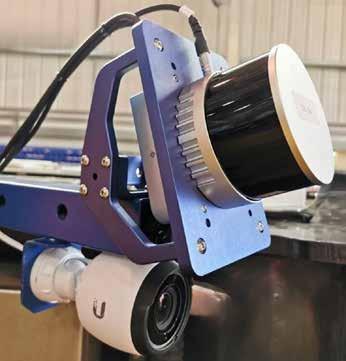
Going beyond the Network Rail standards of a measurement every five or 10 metres, Cordel is producing granular measurements along the line. For the South East Alliance’s platform exam question, the system allows the height and offset to be obtained automatically at one metre intervals, and for platform furniture details to be measured down to centimetre accuracy.
The granular detail enables rolling stock to be procured with a better understanding of the platforms, avoiding issues like ramps deploying onto platforms with insufficient usable width. Furthermore, other useful information such as platform cross fall can be obtained.
With this material, engineers can make decisions balancing all the risks and benefits. For example, resource could be targeted to raise the lowest platforms with the worst adverse crossfall by installing Harrington humps where the usable width is adequate.
Rebeka took up the story. As reported at the last seminar, Cordel won Network Rail’s contract to develop the Railway Gauging Data Solution (RGDS) as the source of the truth for NR’s National Gauging Database (NGD). After the 18-month development and testing phase, the RGDS went live on schedule on 31 July 2023.

2
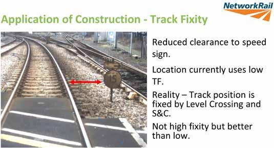
Mark Ward, principal engineer, track in Network Rail Technical Authority discussed improving clearance calculation on which much time is spent, yet collisions with structures are extremely rare. One factor is that clearances are calculated assuming all dynamic movements/tolerances are at extreme limits at the same time. Two key developments are probabilistic gauging (discussed later) and better defined track fixity. GIRT7073 requires that effective track position (EFT) is considered when undertaking gauging calculations. EFT is defined as: “a position that the track could credibly occupy in relation to structures or an adjacent track at some point within its maintenance cycle, giving the smallest clearances.” EFT’s constituents are lateral alignment, vertical alignment, cross level error, and side wear. The first three items relate to track fixity with tolerances shown in Table 2.
These figures do not allow for asymmetric values e.g., where track is strutted against
a platform. All this is defined in RIS-7773-INS, and Mark suggested that there is scope to improve track fixity data requirements. This matters because when clearance is tight, accurate assessment of track fixity can affect whether there is a predicted foul or not. For example, the track fixity might be recorded as low despite the track having high fixity from being fixed to a structure.
Probabilistic gauging
V/S SIC's chair, Dr David Johnson, technical director and Ian Johnston, head of engineering at D/Gauge, presented the path to probabilistic gauging. As Ian advised, all gauging, whether modelled or by old traditional methods using expanded polystyrene applied to the target vehicle, is risk based. Probabilistic gauging is no exception.
The essential difference between traditional absolute gauging processes and probabilistic gauging is how the various variables are used. The former uses fixed allowances, such as those described above in track fixity, and tends to assess the sum of those allowances to estimate the worst case. In contrast, the latter uses statistical distributions based on real variability. This technique is already routinely used to assess electrification clearances and
to enable reduced clearances and so avoid many bridge reconstructions.
David explained that the process technique is in everyday use in other engineering industries having been developed for the US space programme and was first proposed for the railway in 2004 where it has taken a long time to become accepted. But now RSSB is intending in 2025 to publish standard RIS-2774RST ‘Probabilistic Gauging’. It sets out a methodology and a standard set of parameters so that the vehicle/structure interface is modelled in the same way by everyone involved with a new train introduction/ modification. David estimated that probabilistic gauging alone would allow roughly half the current number of substandard/foul clearances to be listed as clear. David also, slightly tongue in cheek, estimated that the risk of an infrastructure strike is some 1,000 times lower that the estimated probability of the world ending today!
An integrated approach
Scotland’s railway has had a deep alliance between operators and infrastructure manager for many years.
Network Rail's Andrew Blakeley is a systems engineer for Capital Delivery in Scotland's Railway and recently undertook a maternity cover secondment
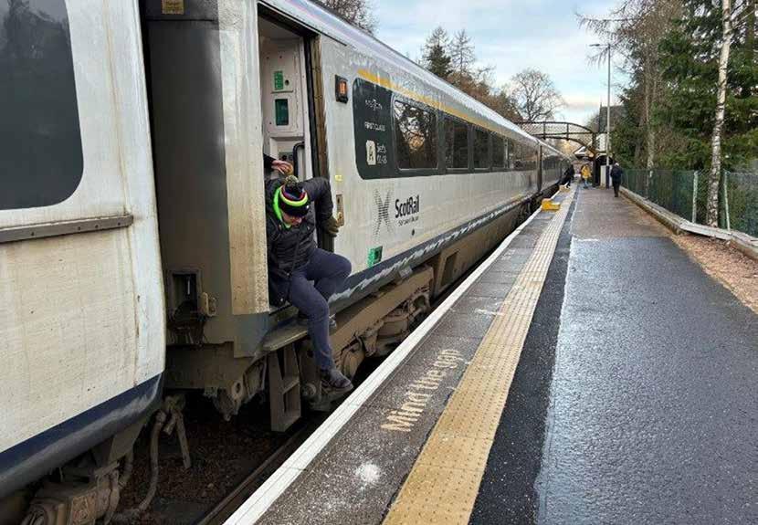
to work as senior gauging engineer. He outlined an integrated approach to gauging. His entertaining talk included the non-engineer view on gauging which essentially is “gauging is a nightmare”. There were many nods in the audience at this point. He explained that Scotland takes the issue of gauging very seriously. The Scottish Government’s 20-page High Level Output Statement included three pages of gauging requirements. As a result, there is a Scottish Gauge strategy document which outlines the approach, although Andrew dispelled the thought that trains might need to shape shift as they cross the border from England. This has led a three-step gauging approach for renewals and enhancements:
» Step 1 – Avoid: recommends that infrastructure is not placed close enough to the track to trigger a requirement for gauging calculations.

» If that is not possible, then Step 2 – Comply: requires that projects comply with existing infrastructure gauges. This means that projects can be sure their design will comply and be signed off. Platform faces are examples.
» Step 3 – Managing noncompliance: this is clearly non-preferred as it brings uncertainties and risk for the infrastructure project as well as making it much harder to introduce new or cascaded rolling stock.
Zoe Boreham, Alstom’s WCE senior expert – gauge, highlighted the importance of a gauging strategy when a new vehicle is being produced. Many people/organisations are involved with gauging a new vehicle. One body – often the train manufacturer – might be in the lead, but customers, sub-suppliers, infrastructure managers, and various approval/certification bodies might all be involved. A good gauging strategy needs to
Very low platform at Dunkeld and Birnam; note footsteps. This platform is being reconstructed.
What should a gauging strategy contain?
1 Introduction -What is the vehicle?
2 Objective - Define the strategy to be adopted to achieve gauging acceptance
3 Key stakeholders -Who are the key stakeholders
4 Requirements -What are the requirements related to gauging
5 Interfaces
• Gauge compliance
• Shoe gear
• Pantograph sway
• Compatibility with train detectionsystems
• Tripcocks
• Electrical clearance
6
Overall Approach to Gauging –which method will be used?
• Using standard vehicle gauges
- Passenger vehicle gauges: PG1 for 20m vehicles, PG2 for 23m vehicles, PG3 for 26m vehicles
7
8
9
10
11
• Using comparative gauging - Needs to be a like for like comparison.
• Absolute gauging - Calculation of clearance between the rolling stock and infrastructure or rolling stock on adjacent tracks.
• Hybrid gauging any combination of the 3 methods above
The routes -Absolute gauging is route specific
The swept envelope model details
• Is it a hybrid model or are all vehicles modelled?
• The track data used to generate the vehicle movements
• Loading conditions and suspension failure cases used
• Effect of cross wind
• The bogie model
• The static cross sections and how these will be managed so the model will represent the as built unit
• Passenger footsteps
• Tolerances to cover variation is dimensions, normal maintenance condition and wear, and suspension stiffness
• Details of the swept envelope validation process
The assessments:
• Structure clearance, passing clearance, stepping distance, pantograph sway, electrical clearance, depots and private sidings assessments
Management of substandard clearances
• Review with Network Rail Gauging Engineer
• Resurvey infrastructure
• Comparative gauging analysis
• Probabilistic gauging
• Operations restriction
• Re-design vehicle
• Infrastructure works to improve clearance
Project Timescales
12 Conclusions
cover all the information that these organisations might need to play their part in the gauging process and a typical contents list is shown in Table 3.
- For freight W gauges where they are cleared is published in the Sectional Appendix
Edward Garner, team lead – dynamics, gauging & testing at AtkinsRéalis Rail & Transit, assesses gauging compatibility and compliance for new and existing vehicles. He presented the consultant’s
incorrect curve radii or cant, transition curve data and platform measurements, as well as lack of confidence in six-foot data. Moreover, data is often out of date with, for example, 87% of structure data over three years old. He then went on to discuss aspirations relating to data quality improvements and making newer data readily available. Table 3
view of the challenges and aspirations within the gauging industry. It should simply take infrastructure gauging data, apply vehicle models, and deliver the result to the customer in the required timescales. However, often challenges with the first two lead to late delivery. Survey data can have errors such as vegetation taken as structures,
Vehicle models can be an issue too, sometimes far too complicated or too simplistic, causing slow or overly conservative assessments respectively. Where comparative gauging is preferred, the comparator vehicle model might be unavailable due to IPR issues. Guidance notes in tandem with updated railway group standards could vastly improve the quality of the gauging models, reducing the time taken to assess them and improving the usefulness of the results.
Tony Ellis, RSSB’s professional head of passenger operation said that there has been a lot of focus on accessible boarding and alighting at platforms but risk also has to be considered. These include, steps/gaps, boarding ramps, adverse crossfall, lack of tactile paving, unattended pushchairs, boarding ramps, trap & drag, passenger behaviour, and aerodynamics of passing trains. The overwhelming majority of the platform edge risk relates to
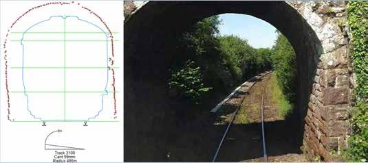
falls from the platform when no train is present.
Rail Engineer suggests that plans to deliver unassisted boarding will help reduce this risk, although providing gap-free level boarding does not necessarily close the gap between train and platform away from doorways.
Platform train interface
The final presentation provided a case study that drew together many of the ambitions and processes described earlier in the seminar. Andrew Brice, head of profession for permanent

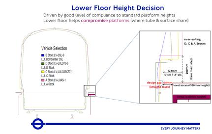
way engineering and David Watkinson, senior engineering lead, both at Transport for London described how the platform train interface issue was managed when three fleets on London Underground’s District, Circle, Hammersmith and City, and Metropolitan lines were replaced by a single fleet designated as S stock.
The Underground sub surface platform height is 950mm and this value probably suffers less variability than is seen on the main line railway, although on some sections the trains share platforms with tube-size trains where the platform height is nominally 840mm. The legacy fleet floor height was a nominal 1100mm above rail. This was the height originally proposed for the new fleet until it was decided to lower the train floor to 980mm to deliver level access at most stations.
Andrew and David described the general challenges of gauging on the Underground where the objective is to maximise the train size, and
(Top) Example of vegetation that data shows as a gauge restriction.
(Left) Passenger fatality risk at PTI versus non-PTI.
(Below left) Comparison of PTI for S stock and the three fleets it replaces on straight track.
(Below right) The effect of canted curves on the PTI.
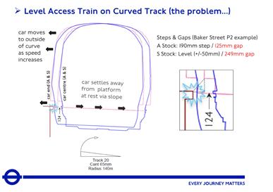
Street platforms 1 and 2 solution.
The rear platform barrier service platform 1 in area A will be moved to the other side of the platform to serve platform 2 instead. Trains in platform 2 will therefore be able to stop 28 metres further along the platform. This and cutting out the three pairs of doors on the rear car will remove all the very wide horizontal gaps on the curves section shown in area B. In addition track slewing and adjustment to Platform 1 will reduce the curvature and hence the gaps in area C.
the challenges brought about by level access. The aim was to achieve a design gap on level track of 64mm which, with tolerances, would be within the Rail Vehicle Accessibility Regulation requirement of <75mm. The challenge was on curves as shown in the adjacent diagram.
This was particularly difficult at Baker Street where platform 2 is on a tight concave curve as the Metropolitan line diverges from the Circle line. This has proved to be quite an intractable problem with various mitigations tested and/ rejected. David described the proposed final solution outlined in the diagram which is expected to eliminate the issue of large gaps at this location.
Even for stations where smaller gaps were theoretically possible, tight control of platform edge nosing stones was required and, in places, adjustments to track as well. Finchley Road, for example, had a gap of 140mm at one end of the platform and a significant ‘foul’ at the other.
A process, described as ‘chasing millimetres’, was aimed at improving RVAR compliance (<75mm gap). Standard platform offsets were reduced from
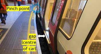
711mm to 695mm, then to 690mm for designated RVAR locations. The risks (principally of platform strike) were considered ALARP, both because dynamic vehicle models were very conservative due to the build-up of tolerances and via observational evidence of known tight spots during initial S Stock runs.
London Underground worked with D/Gauge to consider geometric transitions more accurately, along with probabilistic techniques to demonstrate risk. During the resulting PTI improvement works on curved platforms, both approaches were used separately in trials - 'Transitional' at Monument and ‘Probabilistic’ at Finchley Road – to support not cutting nosing stones back at pinch points.
The end result was that 118 out of 249 platforms were made compliant with RVAR dimensions, 58% of platforms have a horizontal gap less than 150 mm at every doorway,
although 8% have a horizontal gap of above 250mm at one S stock doorway at least.
The seminar clearly showed the importance of collaboration, innovation, and planning in gauging. There were two key messages.
First, everyone wants to be able to contribute to and use a gauging database populated with up-to-date and validated information. Freight operators want to know quickly whether ‘this’ load on ‘that’ wagon can travel from ‘here’ to ‘there’ – a sort of Google Maps for the railway (without the risk of a high load meeting a low bridge).
Passenger operators want certainty about the platformtrain interface so they can deliver solutions that enable unassisted boarding and alighting.
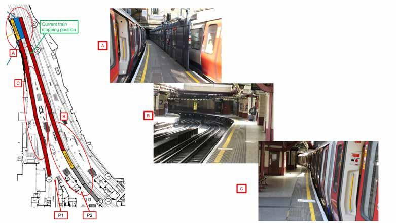
Second, beyond knowing the art of the possible today, the overall strategy should be to continue to upgrade infrastructure built to a variety of shapes and sizes over a couple of centuries. The infrastructure gauge should be standardised for passenger and freight operators to be able to deliver the smoothest railway service to satisfy more customers.
With thanks to the presenters for their assistance with this article.


Railway 200 celebrates the dawn of the ‘Railway Age’, inspired by the opening of the Stockton and Darlington Railway on 27 September 1825. Looking back through the history of various rail developments, it is clear that this should be recognised as a momentous date, because, for the first time, all those developments coalesced to create the first railway as we have understood them ever since, both nationally and globally. The arrival of the railways was possibly the most significant feature of the early part of the industrial revolution, leading as it did to rapid and profound changes in society, business and cultural life.
The coming of the railway was transformative in many ways. It almost annihilated the effects of distance for the traveller, and enabled and encouraged people to explore further afield and to seek employment far from home. It gave manufacturers advantages by reducing the cost and the duration of transport of goods. New markets became readily accessible. In conjunction with the telegraph and newspapers, it would convey opinions as well as people and goods and thereby have effects on political life. It had political effects in linking distant regions (levelling up, anybody?!), while at the same time strengthening central authority.
A ‘proper’ railway
What is the definition of a ‘proper’ railway? It needs to fulfil the following criteria: specialised track; accommodation of public traffic; conveyance of passengers; mechanical traction; and some measure of public control. ‘Specialised track’ means both the provision of a specially formed track with parallel rails to guide vehicles with appropriate wheels and the sole and complete occupation of land on which that
track is laid. ‘Accommodation of public traffic’ distinguishes a railway from a tracked system as part of a private enterprise, for example a mine, a factory, or docklands.
From this definition it can be seen why the opening of the Stockton to Darlington Railway in 1825 is widely celebrated as the first commercial passenger carrying railway. While there had been several examples of ‘tramways’ taking passengers in horse-drawn, rail-borne coaches, it was the first passenger carrying railway powered by mechanical means and not by horse.
Interestingly, after the initial enthusiasm for steam-powered traction, the Stockton and Darlington Railway found that reverting to horse power for much of the journeys over the next few years was more efficient and economical! This remained the case until further development of locomotive design proved it to be the better option. During this period of gaining confidence from improved locomotives, passenger coaches continued to be largely hauled by horse, with freight traffic using the steam power available. Horsepower was not relinquished from the line until 1833.
Woodcut engraving of Stephenson's Locomotive for the Stockton and Darlington Railway from the book "Das Buch der Erfindungen, Gewerbe und Industrien, 2. Band (The book of inventions, commerce and industries, Volume 2)", published by Otto Spamer, Berlin and Leipzig (1877).
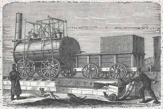
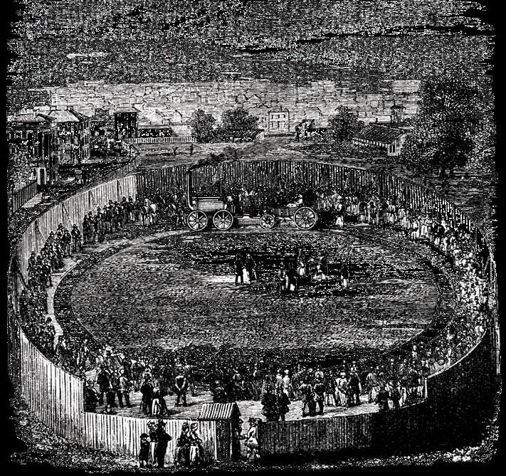
The Stockton and Darlington Railway almost started life as a canal. The coal mines in Durham had a very healthy market for their output in London. The easiest part of the conveyance of the coal was by sea from Stockton-on-Tees. The difficult part was getting it from the coalfields to the port at Stockton. At first, it was proposed that a canal would be built from a point where the coal could be brought by wagon on tramroads from the mines down to a suitable level and then conveyed for the remainder of the journey to Stockton by water transport. In fact, three canals were proposed, the last one being objected to by the residents over whose land it would cross. However, these same residents took the initiative to propose a tramroad as an alternative. Once again, the proposed route was objected to, this time by a fox-hunting lord. After a further change in route
and the replacement of the original surveyor by the appointment of George Stephenson, the proposed railway was authorised by Act of Parliament in 1823. Stephenson advocated the use of steam locomotives on the railway. Originally the track had been planned as a plateway, but locomotives required the track to be built using edge rails instead. Also, as Stephenson had begun experimenting with wrought iron, this material was specified in place of cast iron which, as described later, frequently broke under the weight of steam locomotives. As first built, the railway used the fairly usual system at that time of short rails laid on stone blocks. What differentiated the Stockton and Darlington from previous enterprises, and was almost certainly fundamental to its success, was that it seems to have been the first instance of the large-scale use of wrought iron for the permanent way.
By 1825, the various features necessary to create a new form of transport were all there, including:
Track in many forms, from short wooden or iron rails, usually simply supported on stone blocks, or even from stone ‘rails’, had been used in tramroads in many places over a long period. While canals were important carriers of heavy goods such as coal or stone, tramroads or mineral lines provided an efficient adjunct to bring the goods down to the canal level. These were the canal feeder lines and there were many such lines, particularly in the mining areas of north-east of England and, in Wales, in the Forest of Dean and in the Neath and Swansea valleys.
A suitable locomotive had been developed by Stephenson after Richard Trevithick had demonstrated in 1804 the practicality of a steam locomotive as opposed to stationary engines.
Passenger transport by rail had been trialled at Oystermouth on the Swansea and Mumbles Railway in 1807, showing that tracked conveyance need not be restricted to freight.
The powers given to the Stockton and Darlington allowed users other than the owners to offer carriage of goods and people, being the beginning of a public, rather than a fully private, railway as was the case for mineral and dock railways. In fact, the carriage of passengers on the railway was carried out entirely by external contractors, and not by the proprietors of the line.
But what about development of the track? It might be imagined that the permanent way being specified for this first mechanically-powered, passengercarrying railway had evolved from the earlier forms of track used on the various ‘tramroads’ and mineral lines. This is not entirely the case. The majority of the older tramways used the L-section plateways rather than the ‘edge’ rail. This was to allow the load carrying vehicles, fitted with flangeless wheels to be used on roads as well as on a guided rail system.
Additionally, the preferred method for achieving the correct gauge was to fix the plates to stone blocks rather than using sleepers or any other form of cross-ties. The stone blocks were drilled to allow oak plugs to be installed to receive the fastenings. The absence of any cross-ties avoided any obstruction for the horses walking between the plates. Incidentally, the commonly used term ‘platelayer’ for a permanent way lengthman has its derivation from the days of these plateways.
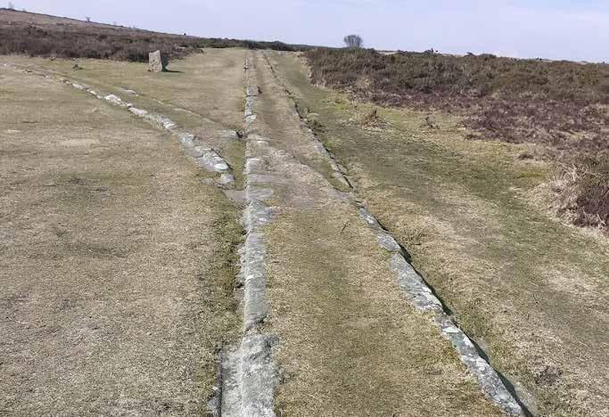
Going a little further back in time, what was the gestation of the metal plateways, with the concept of the flange on the track, rather than the wheel? It may have evolved from trackways using only stone as the construction material. A good example of this is the track system used to carry granite from the Haytor Quarries on the edge of Dartmoor down to the Stover Canal for sea transfer from the Teign estuary. This was used to build such structures as London Bridge and the British Museum. This particular track system, built in 1820, was actually contemporaneous with the metal plateways in common use by that date, but the use of stone was evidently still favoured.
The granite available on the spot was used to build the track, which is formed simply from blocks between 4-8 feet long and about 1 foot square, beautifully crafted into an L-shaped cross-section. The workmanship and labour involved

in producing these must have been enormous, but the finished product was very robust, hard wearing, and long lasting. So much so, that large extents of the Haytor trackways are still very evident and in good condition to this day. In terms of maintenance and repair, they are a striking contrast to the early days of the alternative track forms in use. Once locomotives started to be used on metal rails, whether supported by stone blocks or timber sleepers, much experimentation with the rail profiles, weight, and material was necessary before some degree of reliability became established.
Cast iron rails had been adequate for horse-drawn traffic, but when Richard Trevithick demonstrated his first steam locomotive at Penderryn Colliery in 1804 it quickly became apparent from the number of breaks that occurred that wrought iron would be needed for the increased loading. Similarly, while the first true railways continued for a while to use stone blocks for support, once speeds and loading increased they became inadequate to prevent gauge spread and sleepers became the norm.
So, it is not really true to say that the track form for modern railways evolved from the original tramroads, because after those modern railways came into being the tramroads continued for several decades with their own established system. In fact, both railways and tramroads continued to independently evolve and develop their own systems suitable for their respective uses. They each had a pair of parallel metals in common, but from 1825 onwards they had to fulfil different purposes.
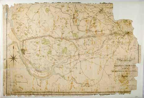
At the start of the nineteenth century, Liverpool and Manchester were respectively dependent on the Bridgwater Canal for the import of raw materials, cotton, coal, grain and livestock, and the export of cloth and other finished goods. From 1800 onwards, businesses in both great cities were looking for a more efficient means of conveyance. In 1822, William James carried out a survey for a possible railway route. A young Robert Stephenson was also in the surveying party. This work was later taken over by the latter’s father, George Stephenson, around the same time as the opening of the Stockton and Darlington. Five years later, there was another historic day, 15 September 1830, when the Liverpool and Manchester Railway was opened. The works had been a major civil engineering project with many large structures, designed with easy gradients apart from a section requiring cable haulage at the Liverpool terminus. The line is particularly famous for Stephenson’s determination in overcoming the problems presented by Chat Moss, a four-mile-wideswamp. He cut drains and laid floating beds of brushwood and heather for month after month until a bottom was touched 25 feet down and a stable embankment rose 5 feet above the surface of the bog. The track for most of the 31-mile route was of short, fish-bellied rails, quite light at only 35lb/yd and supported on stone blocks. The exception to this was over Chat Moss and one or two other short sections, where Stephenson specified timber sleepers to reduce the static load. The gauge, now becoming established practice, was set at 4 foot, 8.5 inches.
By 1832 it was becoming obvious that the Liverpool and Manchester Railway was having track problems. The directors asked George Stephenson to investigate and report on stronger rails. Also at this time, the directors of the Newcastle and Carlisle Railway were using the Walker Foundry to carry out a series of tests on elliptical (fish-bellied) and parallel rails to decide on the best design. However, consultation with a number of engineers only resulted in a lack of agreement. The results were passed to George Stephenson but is not known whether he used these in his report to the board. Apparently, Robert Stephenson also used the results to support a report he gave to the directors of the London and Birmingham Railway in 1834.
The tests were carried out on 15foot elliptical and parallel rails which were each nominally 50lb/yd. Trials
View of the railway across Chat Moss, from Bury's Liverpool and Manchester Railway, 1831.
were made with various distances between supports with progressively increasing loads being applied and the deflections measured. Deflections were lower in the case of the elliptical rails, and this led to a belief in their better strength. Consequently, the Newcastle and Carlisle was laid with these. It was not until a few years later that it was realised that the wrong conclusions had been drawn from the tests. The tests had actually been of ultimate strength, as the rails had been loaded to beyond the elastic limit. The loads applied to achieve this deformation were far in excess of the axle loads to be carried. Soon after this realisation both the Newcastle and Carlisle and the Liverpool and Manchester were re-laid with parallel rails.
Various rail profiles were being trialled throughout these early days of railway development, including the T-section, the inverted and flanged U-section, and the H-rail or I-rail, known as double-headed, which evolved to a stabilised design as the bullhead rail. This rail section became the established stalwart for most railway construction right through until the 1930s, when some experimentation with the more modern flat bottom rail commenced. Meanwhile, over on the Great Western Railway, Brunel decided in 1833 not only to adopt a broad gauge of 7 foot. ¼ inch, confident that this would give better comfort at higher speeds, but also to use a completely different form of track construction, being inverted U section rail (pictured below inset) directly fastened to longitudinal baulk timbers. These timbers were joined at intervals by transverse members or transoms. This system enabled, at least initially, a comparatively light rail section of 43lb/yd.

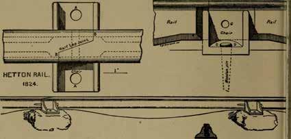
(Above) George Stepnensons Fish-Belly Rail, Manchester & Liverpool Railway, A. D.1829.
Apart from the rails themselves and their fairly quickly accepted best means of support being timber sleepers, there were, of course, many other components and associated aspects of permanent way design to be developed. How to ensure continuity of the rail head across joints, how to fasten rails to sleepers and how to provide the ability to switch rail vehicles between routes were three of the most significant needs.
bullhead rail system was to prove its superiority by the ease with which the rails could be secured by oak keys to cast iron chairs screwed to the sleepers. It could also be easily removed and replaced.
The subject of the design of switches and crossings is too vast to go into detail about here. Suffice to say that even such a simple trackway as that at Haytor Quarries needed junctions to facilitate the access of wagons to several loading areas. A photograph of such a ‘switch and crossing’ makes it look as though there were no moving parts, but, in fact, the wheels were guided by ‘point tongues’, made of either oak or iron, provided to choose one route or the other at the crossing ‘nose’.
(Below) First passenger transport on the English railway line Stockton - Darlington stock illustration.
Originally, joints between rails were simply a case of butting one up to the next on a common support, with both rails then being clamped to that support, whether it be a stone block or a sleeper. Quite soon, a degree of sophistication was introduced by having the two rail ends fabricated such as to overlap each other on the common support. It seems that fishplates, which themselves evolved through various designs, were not generally introduced until 1847.
Various methods of fastening the rails to blocks or sleepers were trialled, ranging from direct fixing of the rail foot to the support or with the use of some kind of ‘baseplate’. Eventually, the
To many railway historians, the Liverpool and Manchester Railway should have the honour of being the first example of a ‘proper’ railway, in that it fulfilled all the attributes as defined earlier in this article. Unlike the Stockton and Darlington Railway, it never even contemplated the use of haulage by horse, championing steam haulage. Also, for the first time, the owners of the line provided the locomotives and rolling stock and ran all the services.
However, the Stockton and Darlington Railway deserves its own place in history, as being the enterprise which really initiated the beginning of the creation of a completely new form of transportation, available to all. It would go on to very quickly bring radical changes to people’s way of life, bring national and global opportunities, and would form a new culture and heritage loved and appreciated to this day.

Simply working & sustainable


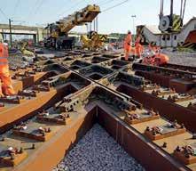
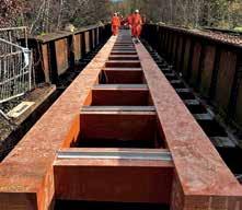
SEKISUI CHEMICAL GROUP : Enhancing Lives, Preserving the Planet. At Sekisui, we’re dedicated to advancing the quality of life worldwide while championing the protection of our planet.


ALL HISTORIC IMAGES: LONDON TRANSPORT MUSEUM COLLECTION
PHOTOGRAPHER ACKNOWLEDGED WHERE KNOWN


(Below) View of broad gauge steam locomotive hauling a train approaching platforms at Baker Street. Broad gauge operations ceased by 14 March 1869.
Just 38 years after the birth of the modern railway in 1825, the first underground railway was opened in London. In case anyone is unaware, the Underground is usually known as The Tube, strictly a term for the small gauge deep lines. Here, we will canter through 162 years of its development and innovation that has helped shape London as a world class city, with occasional references to political events for context, but this is just an outline.
The first 100 years (approximately)
The Metropolitan Railway from Paddington to Farringdon opened in 1863 with the aim of reducing on-street congestion. Originally, it was a partnership between the Metropolitan Railway and the Great Western Railway, the latter keen to extend its broad gauge (seven-foot) lines into the city of London.
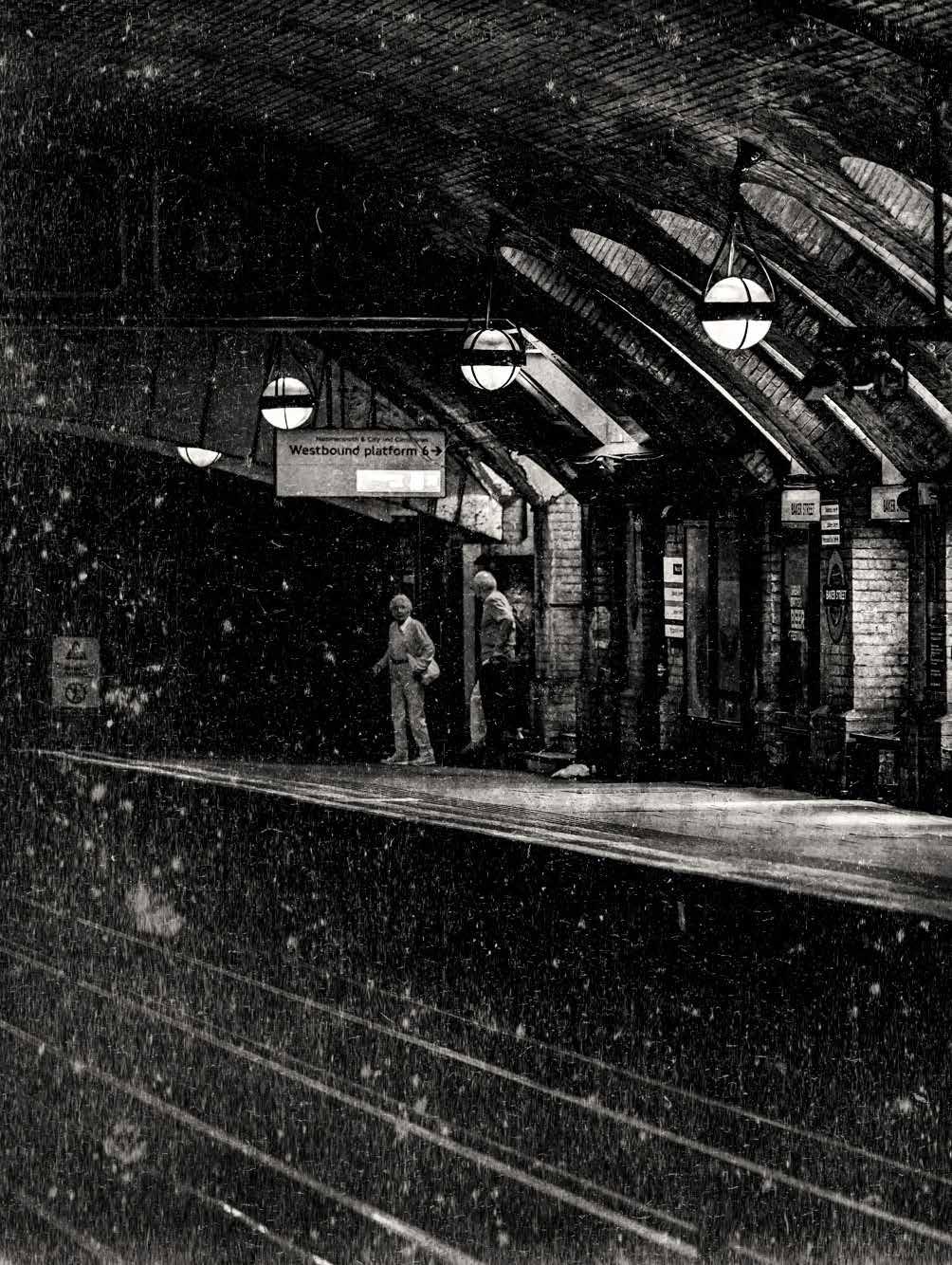
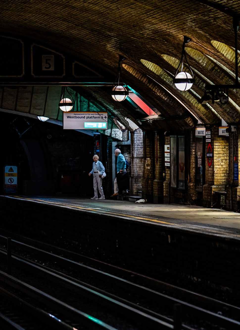
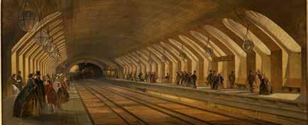
The parties fell out and no broad gauge ever ran to Farringdon. It was built using the cut and cover technique – digging a huge trench in the road, building reinforced sides, and then reinstating the road surface as the tunnel roof. It was operated by steam trains and contemporary reports suggest that conditions underground, even with steam trains, were not as unpleasant as in the street at that time. Incredibly, steam haulage on the Metropolitan line survived until 1961 (Rickmansworth to Amersham).
Since then, the London Underground has grown into a vast system and has witnessed, and often led, many technical innovations. Electrical and telecommunications systems have developed hand-in-hand with metros and, even in 1863, the electric telegraph was a feature.
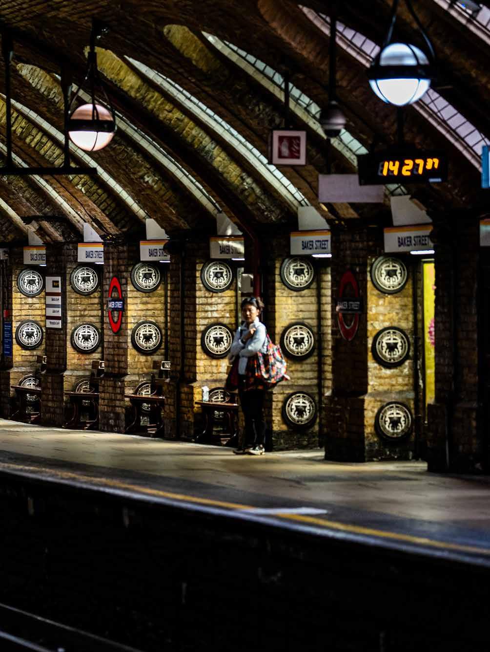
The Metropolitan Railway was a great success and was extended both east and west. A different company, the Metropolitan District Railway, built a line from Gloucester Road to Tower Hill allowing the Circle line, a joint operation with the Metropolitan Railway to start running in 1870, still steam hauled. As an aside, the original builders of these cut and cover steam lines incorporated many ventilation outlets which proved to be very beneficial more than 130 years later when airconditioned trains were introduced.
It became clear that the scale of disruption caused by cut and cover construction could not be tolerated if the underground was to be expanded. It helped that London is built largely on clay, and engineer James Henry Greathead invented a tunnelling technique which used a circular shield to protect miners when digging into the clay prior to erecting cast iron linings. Cost of tunnelling has always been an issue.
The City and South London Railway (C&SLR) was the first line dug with the Greathead shield. The tunnel was only 3.2 metres in diameter but this
was tolerable as the Victorians were quite short. The C&SLR initially ran from King William Street in the City to Stockwell and opened in 1891. It was electrically powered using locomotives hauling cars known as padded cells due to their tiny windows. Passengers accessed the cars via lattice gates at each end of each car, controlled by a staff member.
Metropolitan Railway cutand-cover construction at Praed Street, Paddington circa 1866.
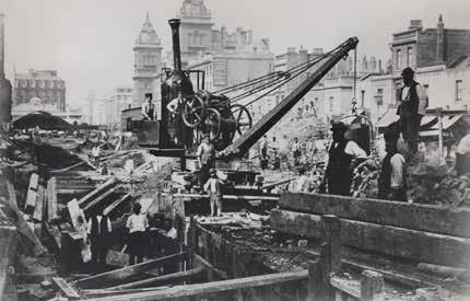
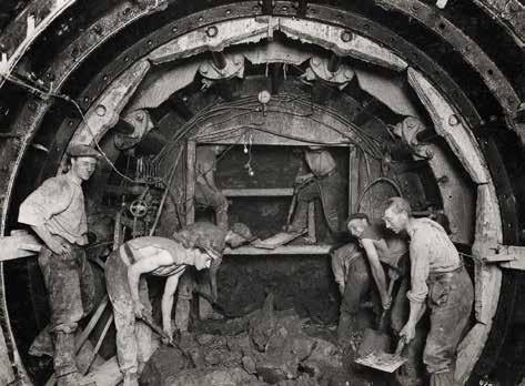
(Above) Work on the Northern Line using the Greathead Shield 1923, Topical Press.
(Below) Original CLR Locomotive and coaches, 1900-1910. The locos were blamed for causing vibration in buildings above the railway.
(Inset) As a result of the issues with the locomotives, lighter motor coaches were developed, seen here at White City circa 1903-06.
In 1900, the second tube line opened. The Central London Railway (CLR), running between White City and Bank, was originally known as the ‘Twopenny Tube’ because of its flat fare of two pence (less than one pence in 2024 currency). Its tunnels were slightly larger than the C&SLR’s at 3.32 metres diameter. Along with extensions, the original tunnels were enlarged during the 1930s to approximately the standard diameter of 3.56 metres. Again, locomotive-hauled trains were used, although trains were longer and its locomotives were more powerful and heavier, the latter factor leading to complaints about vibrations in buildings above the line.
The CLR pioneered so-called hump stations where the lines had down gradients exiting from stations aiding acceleration, and up gradients approaching stations reducing brake wear.
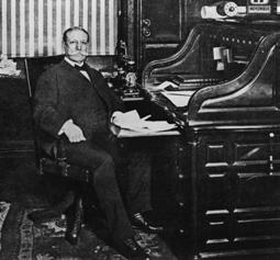
(Above) Charles Tyson Yerkes on 17 November 1900. Yerkes succeeded in developing London's Edwardian Underground system by financing three Underground lines: the Bakerloo, Piccadilly, and Northern lines. He also financed the conversion of the District line from steam to electric power. Yerkes also created the Underground Electric Railways of London. He died in 1905, before any of the new railways opened.
In the meantime, there was pressure to end steam haulage underground. There was debate between the Metropolitan District and the Metropolitan Railways about the type of electrification to use. The Metropolitan Railway proposed AC power whereas the Metropolitan District Railway proposed a nominal 600 VDC insulated return system using two conductor rails. After arbitration by the Board of Trade, the latter system was chosen. Power stations were built, respectively at Lots Road, Chelsea adjacent to the Thames and at Neasden.
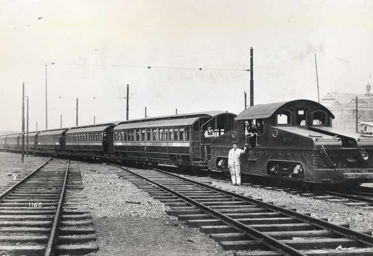
Electrification was implemented in 1905, along with the adoption of multiple unit control and the adoption of powered signalling and tripcock/trainstop protection to stop a train if it passed a signal at danger (SPAD). Many of these innovations were imported from the USA following the influence and ownership of the American, Charles Tyson Yerkes.
Yerkes was a key figure in the history of London’s Tube described by the London Transport Museum (LTM) thus: “Yerkes used shrewd and sometimes shady tactics that proved necessary to realise a modern Tube network for the twentieth century. He founded the Underground Electric Railways Company of London (UERL) in 1902, which brought together several modes of transport under one umbrella, ultimately moving towards a unified and cooperative transport system.”
When originally built, cut and cover station platforms were accessed by stairs, and deep tube platforms by lifts which were sometimes hydraulically operated. In 1911, the first escalators were introduced to serve the Piccadilly line at Earls Court.
While there was some initial reluctance, the public soon took to them and the escalators’ ability to move large numbers of people meant that many central London stations were reconstructed over the following decades to replace lifts by escalators. This has left stations with many abandoned shafts and passageways which have often been adopted by engineers for ventilation or other purposes. The LTM runs a popular programme of tours to many of these sites branded Hidden London.
By 1919, the central parts of what became the Piccadilly and Bakerloo lines had been built and the period following the end of the First World War saw the introduction of the first trains with compressed air powered sliding doors. It would take until the early 1950s until the last train with hand worked doors was withdrawn.
After various consolidations and company amalgamations, by 1920 the UERL controlled all lines apart from the Metropolitan Railway. The C&SLR had been extended south to Tooting and northwards to Euston. In the 1920s it was decided to amalgamate the Charing Cross, Euston, and Hampstead line with the C&SLR to become the Northern line we recognise today. A new depot in the ‘village’ of Golders Green was opened to receive the first of what became a large fleet of so-called standard stock built with various designations from 1923 and 1934. Interestingly some of those vehicles were delivered to the depot using steam traction engines. Although, in practice, the trains were far from standard, they could couple to each other. The post-1930 standard stock
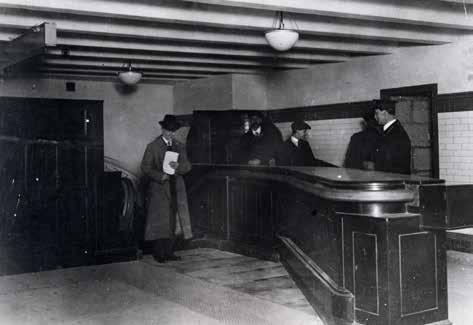
incorporated innovations such as electropneumatic brakes (also retrofitted to earlier trains).
1933 saw the formation of the London Passenger Transport Board, an arm’s length public company that took over the Underground Group, the Metropolitan Railway, all bus, trolleybus and tram operation in Greater London. Its chairman and managing director were Lord Ashfield and Frank Pick (pictured below), respectively. The two leaders created an integrated organisation, developing and/ or influencing standards many of which are still relevant today.
(Above) Upper landing of the escalator connecting the District and Bakerloo/ Northern line platforms at Charing Cross (now Embankment) station circa March 1914 similar to the 1922 Earls Court machines. Note original system where passengers move to the side when exiting an escalator.
(Below) Piccadilly line 1931 “standard”-tube stock motor car no 3130, built by the MetropolitanCammell Carriage & Wagon Finance Co, and Birmingham Railway Carriage & Wagon Cobuilt. trailer car no 7063: Topical Press.
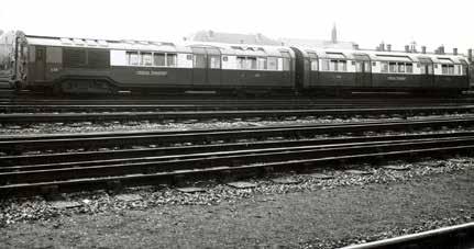
Clockwise from top left: 1) 1935 tube stock prototype with streamlined front; 2) This had a central driving position (seen here with the seat reversed); 3) the third prototype had a conventional flat front adopted for the production 1938 tube stock; 4) seen here on the Bakerloo line in 1958: 1-3) Topical Press, 4) Dr Heinz Zinram.
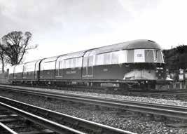
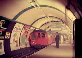
(Right) P-stock motor car. This one was reconstructed from two cars badly damaged in the Second World War 'blitz'. The left hand section was originally a trailer car and the right hand section was originally a motor car. It was rebuilt at Acton Works: Topical Press.
(Bottom right) First aluminium bodied R49stock car, en-route to the 1951 Festival Of Britain exhibition demonstrating the aluminium construction with the left hand one third left unpainted: Daily Herald.
William Sebastian Graff-Baker (18891952), Assistant Chief Mechanical Engineer of the Underground Group from 1922, and Chief Mechanical Engineer (Railways) LPTB, from 1935. W S Graff-Baker headed the design team at Acton Works responsible for the experimental streamlined 1935-tube stock, 1938tube stock, and the O, P and Q38 surface stock cars: Walter Bird.
The 1930s brought many extensions to serve and/or promote London suburban development, although some of the extensions were not completed before the Second World War and some were abandoned following the creation of the green belt after the war. An important development of the small gauge tube trains was moving all the electrical equipment from a large compartment behind the driver’s cab onto the underframe. This allowed almost one extra car length of passenger accommodation on a seven or eight car train. Prototype trains, including an unsuccessful attempt at streamlining, were built in 1935, leading to a large order for the 1938 tube stock (with further cars built in 1949). These operated on the Northern, Bakerloo, and Piccadilly lines, and even on the surface gauge East London line for a while. The last two trains were withdrawn in 1988 after 50 years’ service, although one lovingly restored four-car set remains in active service with the LTM. This type of tube train configuration was to last for over 90 years and was pioneered by engineer William Sebastian Graff-Baker.
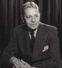
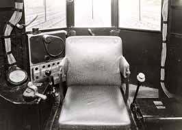

The District, Circle, and Hammersmith and City lines also received new trains in the 1930s. These large profile trains, O and P stock, featured distinctive flared sides in keeping with the style consciousness of that decade.
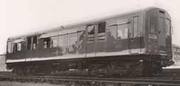
However, the biggest innovation was the Underground’s first use of regenerative braking, long before power electronics made this feature routine. This was provided by Metadyne machines, a type of DC rotary transformer. Each one weighed four tons and cannot have been all that reliable as, in the 1950s, conventional resistance controllers almost identical to those on the 1938 tube stock were fitted instead.
In the 1950s, even though finances were tight, innovations continued. For the District line, the R stock was developed which looked almost the same as the previous O and P stock, and the first batch was of steel construction. The second batch, known as R49, used aluminium construction for the first time and every car was motored.
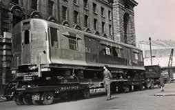
Eight car R-stock District line train made up of five aluminium R59-stock non-driving motor cars, and three steel-bodied R38-stock driving motor cars, painted to match: Dr Heinz Zinram.
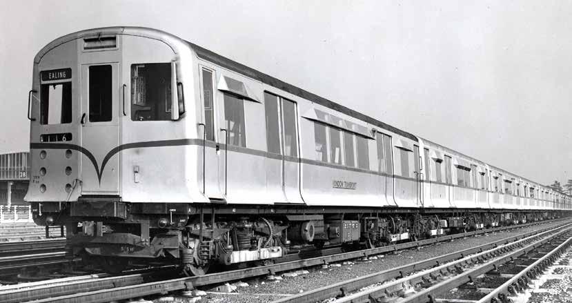
In contrast, the 1950s tube stocks retained steel underframes although unpainted aluminium body panels were employed and –innovative for its time – rubber suspension was used on the bogies, a feature that has persisted ever since.
This decade was also a time of innovation in signalling and control aimed at more efficient operation. The department was led by Chief Signal Engineer Robert Dell. In 1957, the first programme machine was introduced. This was a device where the timetable was encoded on a punched roll of material which moved across contacts to control points and signals somewhat like a punched roll in a player-piano.
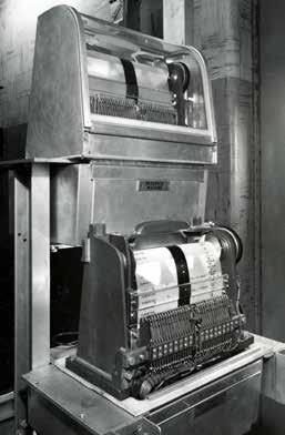
They were a key element in the development of operational centres controlling each line rather than individual signal boxes, but have now all been replaced by computers.
In the 1960s, after nearly 20 years of planning, funding was found to build the Victoria line. With the benefit of hindsight, it was wrong to build it to tube gauge as by today’s standard the trains and stations are too small. But, at the time, funding was tight and the cost of building bigger tunnels was deemed to be too high. There was a lot of innovation in civil engineering. Test tunnels were built in 1960 using an experimental, hydraulically powered, rotary shield ‘drum digger’ which was a forerunner of today’s tunnel boring machines.
(Left) Two programme machines at Watford (Metropolitan line) interlocking machine room 1958. Plastic rolls used on the programme machine contain the complete timetable for a whole day. The holes punched in the rolls permit the completion of an electric circuit which in turn operates the signal interlocking through relays. This in turn adjusts the points and signals: Dr Heinz Zinram.
(Below) Kinnear - Moody drum digger in Victoria line station tunnel at Green Park, being hauled through after completing southbound running tunnel from Victoria – 1965: H K Nolan.
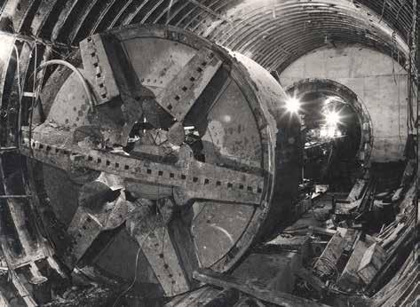
‘Umbrella’ bridge constructed over Oxford Circus to permit the new Victoria line ticket hall and escalator shafts to be constructed underneath; 1963. Bottom right photo shows in use. Top L, HK Nolan, Top R, Bottom L, W H R Godwin, Bottom R, Brooks.
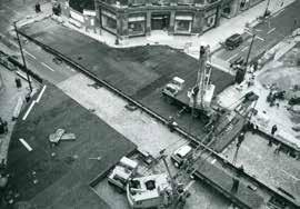

Concrete tunnel lining segments were used for the first time too, and there were other innovations. The new ticket hall at Oxford Circus station was to be located under the busy road junction and the Underground’s engineers developed a so-called Umbrella Bridge to allow construction to take place without interrupting traffic.
The line was laid out largely ignoring streets, unlike most previous lines, allowing shallower curves and the two final termini (Walthamstow Central and Brixton) included overrun tunnels and shallow angle crossovers on the station approaches allowing trains to run into these stations on the normal braking profile. These features enabled efficient operation of the world’s first automatically controlled passenger railway. The technology for this was largely developed by the Underground’s engineers and was manufactured by the Westinghouse Brake and Signal Company (WB&SC, now Siemens Mobility). This system was electronic, but in the days before integrated circuits let alone microprocessors!
The automatic 1967 tube stock trains (the first tube trains with rheostatic brakes) were to be operated by one person and there was a requirement for continuous communications between the control centre and drivers. Whether because of unavailability
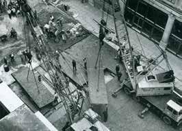
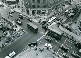
of frequencies or concerns about propagation of radio signals through tube tunnels, it was decided to use a system where the audio signal was sent to/from the train via a frequency modulated ‘carrier wave’ system superimposed on the conductor rails/collector shoes (think Powerline plugs for distributing home networks over the mains cables).
Other innovations included CCTV to help the driver check that the rear of the train was clear before closing the doors; trainborne public address; and a train-to-train radio system to allow the driver of a failed train to speak directly to the driver of an assisting train.
The first century of Underground innovation in London was marked by significant advancements and milestones. From the pioneering days of the Metropolitan Railway to the later efficient, and expansive network, the London Underground has continually evolved to meet the needs of its passengers. Innovations in tunneling, electrification, and train design have all contributed to making the Tube a world-class transportation system.
As we look to the 1970s onwards, electronics, computers and systems integration will become significant features, demonstrating that the London Underground remains a vital part of the city's infrastructure.
Warren Street station
Victoria line 1969: Dr Heinz Zinram.

To be continued…



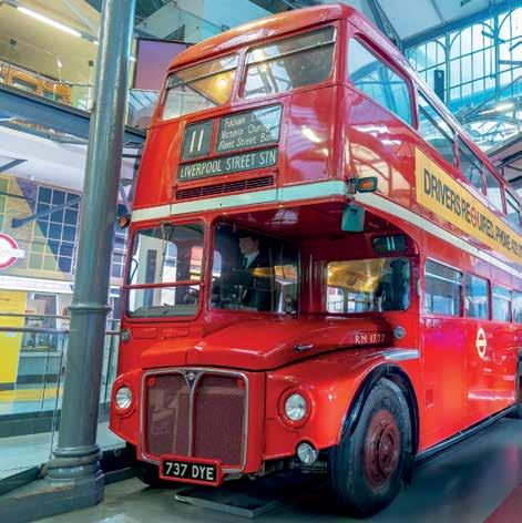


In March 2025, Rail Partners, the Rail Delivery Group (RDG) and the Rail Safety and Standards Board (RSSB) hosted the Fleet Cyber Security Conference, at Thinktank Birmingham Science Museum. The event brought together fleet operators and owners and their supply chain to share cyber security best practice and real-world case studies. The conference discussed practical measures the rail industry is using to reduce cybersecurity risks to rolling stock fleets.
It was a follow up to its Fleet Software Integration and Cyber Security event in February 2024, covered in Issue 208 (May-June 2024). Last year’s event highlighted the issue, outlined some of the tools and techniques available to operators, and explained the difference between Information Technology (IT) systems (generally fairly standard suites of applications on relatively standard hardware) and Operational Technology (OT) systems (generally bespoke software and hardware systems controlling the rolling stock). Speakers also explained that it is sensible to have what is known as a demilitarised zone
between IT and OT with no direct connection between them.
This year, there was more focus on both dealing with cyber threats, and the development of standards and processes to support operators working with increasingly complex connected systems. The fact that the general public now has access to on-train systems through Wi-Fi was also highlighted as a risk that could be exploited by socalled bad actors.
Nicole Jennings, chief delivery officer at RDG previewed the forthcoming Rail Cyber Security Strategy, emphasising that
managing cyber security is vital, given the fact that rail systems are increasingly digital and interconnected. Cyber security is a risk that is consistently evolving, so rail operators cannot eliminate the risk but can mitigate the impact using a consistent and systematic approach to information security. The Strategy is due to be launched in Summer 2025.
Nicole said that the Strategy will help operators to understand cyber risks and the impact of cyber incidents; protect railway assets by safeguarding the confidentiality, integrity and availability of digital systems; and detect abnormal behaviours in people, assets, and/or systems and respond in a way that reduces the impact of cyber security incidents.
There will be five objectives: » Everyone should understand cyber risks, their role in mitigating them, and how to recognise and respond to threats.
» Everyone has a clear picture of exposure, together with their role in identifying weaknesses and assessing potential impacts.
» Security measures are applied uniformly across cyberspace, physical locations, and organisations.
» Security is embedded from design to decommissioning, with continuous adaptation to emerging risks.
» Strong monitoring and detection processes are in place to help in acting quickly to minimise damage.
Security and safety
These five points are quite similar to the process that a railway would carry out to identify and manage hazards and risks, as became apparent when James Walker, head of digital safety at ORR, and Darren Fitzgerald, principal electrical and systems rolling stock engineer at RSSB, spoke.
James identified the links between security and safety in a useful diagram.
Although described separately in English, Rail Engineer notes that ‘security’ and ‘safety’ are the same word in many languages. It was no surprise that ORR expects duty holders to manage the risks arising from software and cyber security failures such as overcrowding, disruption, and signalling system failures. This means that duty holders should manage their software-based system so that software design, operation, maintenance, and cyber security risk is managed in the same way as any other risk as part of their safety management systems.
The approach should be managing security risk, protecting against cyber-attack, detecting cyber events, and minimising the impact of such events. Safety and security specialists should therefore work together to identify and mitigate risks.
James outlined the findings of some ORR inspections. He commended some good practice such as dedicated cyber/information security teams and good support for cyber security throughout the organisation. In contrast, he said, there were many areas for improvement in areas such as coordination of approach to
manage safety and security, lack of cooperation between safety and security teams, together with supply chain and change management assurance issues.
Darren Fitzgerald outlined applicable standards, describing how the Purdue Enterprise Reference Architecture (PERA) model can be applied to on-train networked systems.
(Left) Links between safety and security. (Below) PERA model.
He also outlined the likely scope of the forthcoming IEC 63452 proposed standard on Railway Applications – Cybersecurity which will cover the areas listed in Table 1. It is likely to be published in March 2026.
Darren also introduced Technical Note 2312 Rolling Stock – Cyber Security Essentials. It covers security compliance, physical security and other measures, management of change including control and configuration of assets and systems, system interfaces, and an appendix listing standards with potential cyber security implications. Finally, forthcoming RSSB developments include an update to RIS2700-RST Verification of Conformity of Engineering Change to Rail Vehicles I with appendices on software and cyber security. There will also be a training course – An introduction to rolling stock digital systems – which will include an overview of system models, a high-level introduction to software, and how to understand cyber security in a basic format. Table 1
Key areas to be covered in IEC 63452
Northern Trains’ Cyber Management Process.
Credit: George Copeland/ Marc Silverwood
Northern Trains
Northern Trains’ Operator-Supplier interface. Credit: George Copeland/Marc
Silverwood Northern Trains
Northern’s experience
George Copeland and Marc Silverwood described Northern Trains’ progress with cyber security over approximately the last 10 years from being a railway with no on-board OT systems to today where Northern has more than 360 ‘digital’ trains, over 650,000 WiFi users, and more than 36,000 digital assets across its fleet.
In 2021, one of Northern’s suppliers suffered a cyberattack which took Northern’s on-train systems offline. However, after a team effort they were only offline for an hour. This experience led Northern’s board to establish an on-board systems team of approximately 10 engineers and it has clearly established roles and responsibilities defined for cyber throughout the organisation and with key suppliers. Some activities involved protection against
Apoorv Shrivastava from RSSB discussed the work of the industry led Asset Integrity Group (AIG) which aims to bring cross-asset activities together as part of RSSB’s overall Rail Health and Safety Strategy with a mission where “Asset integrity [is] at a level where it isn’t noticed”. He introduced RSSB’s very readable ‘Cyber security for railway asset managers’ publication.
attacks via, for example, ontrain Wi-Fi, while other tasks included physical security of on-train equipment – e.g., equipment cupboards secured by non-generic keys.
George and Marc emphasised the importance of change control, explaining that an apparently straightforward connection of one on-train system to another can cause unexpected cyber risks. Comment was made that the usual process of handover of new trains and/or other equipment to an operator at a point in time is not appropriate for cyber risks which are constantly evolving, and a more enduring commercial arrangement is needed to ensure an ongoing relationship to enable new threats to be dealt with. Northern explained its cyber security management process and its operatorsupplier interface.
Apoorv outlined some of the work sponsored by the AIG including model risk assessments that others can adapt or follow a similar process. He further emphasised the increasing reality that cyber security is just another specialism in overall asset management, as well as safety/ risk management. Good asset management involves asset knowledge, asset competence, and strategic influence. For complex assets, the skills/ disciplines required are broad and include cyber competence. RSSB is also facilitating a rolling stock Industry 100 (i100) project. I100 is an initiative from the National Cyber Security Centre to facilitate close collaboration with the best and most diverse minds in UK industry.
During a panel session, it was clear from the questions that the importance of having
the right people specifying and assuring cyber security of systems is not always recognised. Moreover, there needs to be cooperation between all the actors involved with rolling stock – ROSCOs and TOCs, as well as train manufacturers and their suppliers.
Unusually, this seminar included a workshop session covering various stages of managing a cyber-attack, highlighting the importance of preparedness and expertise. Your writer has participated in many such tabletop exercises over the years, generally dealing with events such as collisions or derailments. The basic process for dealing with a derailment is similar to that for dealing with a cyber-attack, but the experts who need to be involved are different. However, unlike a derailment, not being able to immediately see what has happened further emphasises the importance of preparation and protection.
Manufacturer’s view
Bruno Corasolla from Hitachi Rail presented a manufacturer’s view. He further emphasised the importance
of collaboration with transparency and feedback loops across the supply chain, from funders through to software developers. He felt that standards such as IEC62443 will help, together with ensuring compliance and sharing best practice (i.e., integrating cybersecurity measures into all stages of the supply chain).
Part of the challenge is that systems are increasingly complex, technology changes continuously, there can be resource constraints, and there are issues with diverse stages of maturity. Rail Engineer heard the solution to all this is commitment, collaboration, and more collaboration, while prioritising cyber.
Summing up
George Bearfield from Rock Rail, who gave the keynote at last year’s event, summed up the day, asking if cyber security really is that that complicated, and what should be done. He said that IT and OT is now well understood and stressed the importance of making assets secure by design (another parallel with safety), using the standards to help.
George acknowledged that cyber competence is improving. He said that it is important to understand system risks and vulnerabilities, and penetration testing can be a valuable tool. Indeed, for systems that have evolved with many changes, penetration testing can be useful as a penetration tester has to understand the system and data flows in order to carry out the tests. This is something that usually cannot be learned from the documentation.
While progress has been made, George concluded, the landscape keeps changing especially with the current unstable world political situation.
This was another valuable event organised by Rail Partners, RSSB, and RDG in collaboration. However, while Rail Partners has now shut down as a result of the planned industry changes, Rail Engineer understands that RSSB and Rail Delivery Group will work together to promote future events.
With thanks to David Gould at RDG and Mark Oakley at RSSB for their assistance.
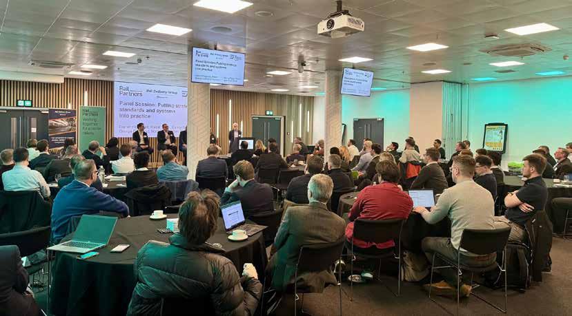


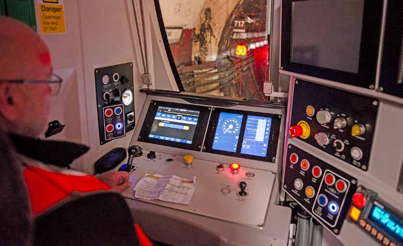
Network Rail’s report ‘CP7 delivery plan – Our approach to digital signalling (OADS) in CP7’ states that “ETCS (European Train Control System Level 2) is cheaper to deploy and maintain than conventional signalling and requires less infrastructure out on track,” adding “this means we can replace more life-expired signalling in each control period.”
The OADS report also states that ETCS improves the safety and performance of the network. However, it acknowledges that, although the capacity benefits of ETCS have yet to be quantified at a network level, ETCS offers significant performance opportunities. For example, it avoids limitations associated with signal positioning and signal sighting. It would therefore seem that there is a strong case for the ETCS programme, especially as Network Rail considers that the Signalling Equivalent Unit (SEU) renewal rate for conventional signalling is £420,000 and that for ETCS installation is £315,000. Yet elsewhere, the OADS report acknowledges that there are fleet modification and capability-building costs. It estimates that these amount to £0.9 billion.
The OADS report also notes that Scotland’s Railway has no plans to implement ETCS in CP7 as it has other strategic priorities. The priorities of the Scottish signalling strategy are to: maintain safety and operational performance; reduce whole railway system net cost; and avoid high unit costs and premature obsolescence. Rail Engineer understands that these are common priorities throughout Network Rail. Nevertheless, Scotland has no plans for ETCS.
It is therefore important to understand why Scotland’s railway considers that there are other, more cost effective, ways of achieving objectives that are generally common throughout Network Rail.
The Scottish view
Network Rail Scotland’s signalling strategy is described in Appendix B of Scotland’s Railway CP7 Delivery Plan which is entitled ‘Signalling Scotland’s Future’ (SSF). Although this identifies potential benefits of in-cab signalling on some lines, it also considers that large implementation costs currently outweigh the potential benefits.
A significant difference between the Scottish approach and that of Network Rail’s OADS report is that the Scottish report considers that the high cost of retrofitting a wide range of existing rolling stock to the current ETCS specification is disproportionate and far greater than money saved in signalling assets. It reaches this conclusion by drawing lessons from other in-cab signalling projects on comparable networks across Europe.
The SSF therefore recognises that, in view of these affordability challenges, ways must be found to extend the signalling infrastructure’s lifespan.
Furthermore, the introduction of new stock may require costly ETCS infrastructure upgrades. This was the case when new Class 197 units were built
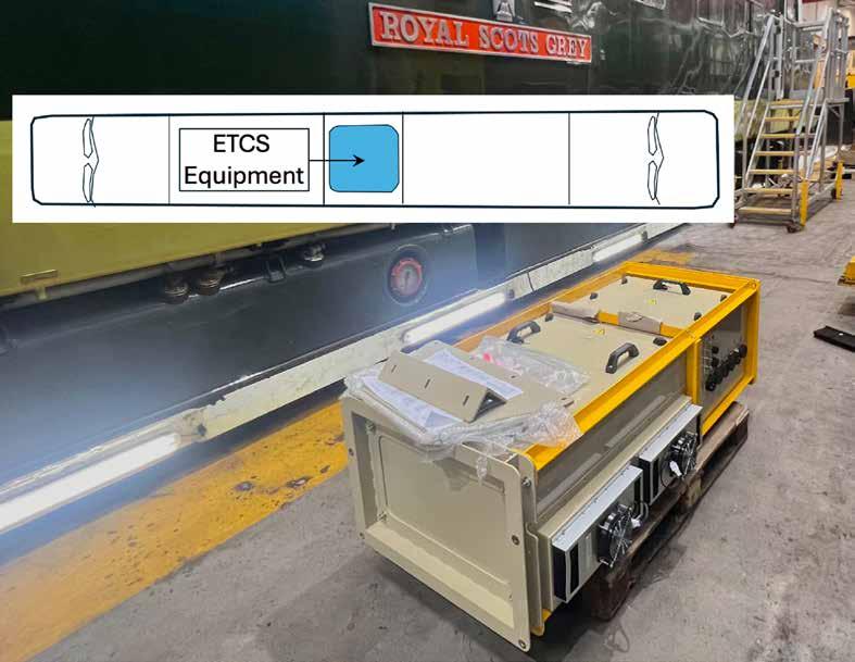
for the Cambrian line. These have the CAF AURIGA ETCS system compliant with the latest specification. However, before they could be used on the Cambrian line its ETCS had to be upgraded to baseline 2.3.0d at a cost of £3 million.
The SSF report considered an alternative ETCS implementation strategy of restricting ETCS deployment to lines that only operate new fleets. However, as demand for passenger and freight services changes over time, restricting rolling stock deployment options on key lines of route was deemed to be unacceptable.
This report also notes that Scotland’s Railway delivers signalling at much less cost than the national average of £420,000/SEU. For example, on a recent project for Aberdeen and Central Scotland the average SEU cost was £356,000. This further weakens the case for ETCS deployment.
Furthermore, the SSF report notes that once ETCS has been implemented there are high costs associated with future infrastructure changes. For example, Rail Engineer understands that
flood prevention works on the Cambrian line requiring the track to be raised required ETCS software changes costing in the order of millions of pounds.
A new train ordered today with ETCS onboard equipment will probably use that supplier’s equipment and, broadly, the cost will be ‘lost’ in the overall cost of designing, building, testing, commissioning, and assuring the fleet. Retrofitting ETCS is another matter, and its high cost was recently highlighted in a European Commission (EC) report on ERTMS on-board deployment. This showed that, for a fleet of 20 vehicles, the average retrofitting costs have grown from €450,000 to €900,000 per vehicle, and upgrade costs have increased from €200,000 to €400,000 between 2018 and 2022.
In all the publicity about retrofitting ETCS to the modern steam locomotive Tornado, cost has not been mentioned. Yet Rail Engineer has been advised that it is costing around £10 million to fit ETCS to a Deltic diesel locomotive. It
is also reported that it cost £11.3 million to design and fit prototype ETCS to a Class 387 Electrostar train operated by Govia Thameslink Railway. Hence the cost of a first-inclass ETCS retrofit is around £10 million. Of the 1,200 or so cabs that need to be fitted with ETCS equipment for the East Coast Digital Programme (ECDP), 700 will be retrofits for about 20 different classes of locomotives, on-track plant or passenger units with each class requiring a first-in-class design. ETCS fitment will often require power supply to be reinforced (or provided from scratch), finding the required space and providing mountings for all the equipment and sensors. The EC report on onboard deployment considered that such fitment costs are only 50% of the total deployment costs with the remaining costs being design, validation and assurance. This illustrates that the cost for one off vehicles or very small fleets might be disproportionately high.
New trains may have ETCS or be ‘ETCS ready’ with available space and possibly the required wiring in place. Yet they may incur additional
The large ETCS equipment box for Deltic locomotive which is fitted in that compartment that had a coach steam heating boiler.

costs if the hardware and software have to be upgraded to the latest baseline, especially if ETCS has to be integrated into the vehicle’s train control and management system. Recently, it cost £33 million, or £175,000 per cab, to upgrade the Thameslink Class 700 fleet.
Network Rail aims for a gradual ETCS rollout around the country starting with the East Coast Digital Programme (ECDP) on the East Coast Main Line (ECML). The next phase is between Biggleswade and Fletton, south of Peterborough where there will be no lineside signals. Hence all passenger trains, freight locos, on-track machines, and monitoring vehicles on this section will have to be ETCS equipped.
Thereafter, Fletton to Stoke Tunnel near Grantham is planned to be completed in the early 2030s. This section
will have a conventional signalling overlay so that trains on routes crossing the ECML at Peterborough and Grantham do not need to be ETCS fitted.
Hence the early ETCS programmes will require high numbers of trains to be ETCS-fitted and many of these will require retro fitment. However, in the long term, as ETCS is rolled out and new trains purchased a diminishing number of trains will require retrofit.
The Signalling Scotland’s Future strategy recognises the benefits of ETCS but considers it will only be affordable if:
» Transitions must avoid any disproportionately expensive retro fitment to any of the rolling stock which operates on the route.
» Overlaying ETCS on conventional signalling
during a transition period is affordable.
» ETCS deployment must not reduce the flexibility of deployment of existing rolling stock.
» The process to alter safety critical software and data relating to the railway infrastructure must be improved so that it’s no longer disproportionately expensive.
Network Rail’s OADS report and the Scotland’s Railway SSF report reach quite different conclusions in respect of the affordability of ETCS. This is because the SSF report identifies factors that add to installation and upgrade costs that are not mentioned or are understated in the OADS report. In particular, the SSF highlights the high cost of retrofitting ETCS to existing stock which reflects concerns in a recent European Commission (EC) report. The OADS report allows £0.9 billion for fleet fitment which at emerging prices in the EC report is 1,000 trains or about a quarter of the UK passenger fleet, excluding freight locomotives.

Although ETCS offers various benefits, it is difficult to see how the UK railway can afford a large scale ETCS implementation programme unless the affordability issues that Scotland’s Railway have identified are addressed.
Editor’s note: Our feature “Planning for ERTMS and timetable implications” provides more information about Network Rail’s approach to the implementation of ETCS


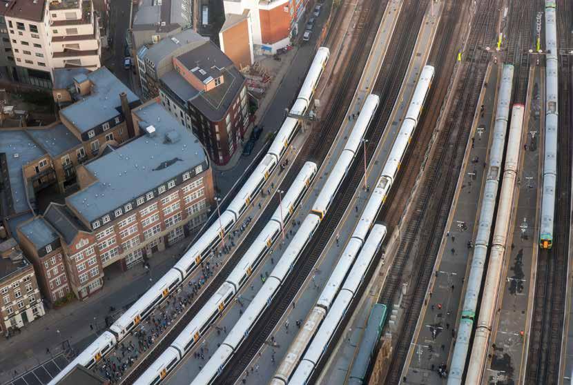

Much has been written and continues to be written on European Rail Traffic Management System (ERTMS) / European Train Control System (ETCS) and the benefits it can bring to the railway. In short these may be summarised as the reduction or even elimination of lineside signal infrastructure, the creation of greater capacity, and lower costs. All are admirable objectives but have the practicalities of achieving them really been thought through?
A major challenge could be optimising train timetable planning in an ETCS world. A recent talk given to the IRSE London & SE Section by Nadia Hoodbhoy, a principal engineer for Control & Command within Network Rail, was indicative of the multitude of factors needing to be considered.
ERTMS and the challenge
Just a brief reminder as to what ERTMS is all about. It has three component parts:
» ETCS which is the signalling aspect and has three levels - L1, L2, and L3. L1 is essentially a standardised Train Protection System which is discontinuous but prevents drivers ignoring lineside signals. L2 provides Movement Authorities (MA) to drivers in the cab with fixed block sections and can result in lineside signals being removed or in conjunction with lineside signals. L3 moves toward a total radio-based system incorporating moving block where trains can close up in dense traffic areas and hopefully traditional train detection systems, e.g. track circuits and axle counters, can be dispensed with.
» GSM-R and its intended replacement FRMCS, which is the radio link to connect all the data and transmit it between control centres and trains.
» The European Traffic Management Layer (ETML) aimed at producing a standardised Traffic Management System (TMS) but which has never got off the ground. TMS information is alternatively provided by proprietary systems.
Pragmatism has introduced a variation on ETCS L2, known as Hybrid Level 3 in which a mixture of trains fitted either with L2 or L3 can operate on the same sections of track with an L3-fitted train followed by another L3 fitted train being given an MA that allows a closer spacing using moving block principles. Should the following train only be fitted with L2 equipment, then an MA can only be given to the end of a fixed block section. If all trains on the route are fitted with either L2 or L3, then lineside signals can be removed. However, it is more likely that the route will also carry non-fitted trains and thus signals have to be retained.
Widespread opinion is that conventional signalling is too expensive and that moving to ERTMS is the only way to significantly reduce costs. How is this measured? The method is by assessing the cost of a Signalling Equivalent Unit (SEU) that gives comparisons for different technologies to signal and control a typical section of railway. At present, an SEU costs in excess of £419,000 for conventional signalling (at pre-Covid price levels) and £315,000 for an ETCS Level 2 with signals removed. Even this is viewed as too much and a programme named Target 190 was launched in 2019 to reduce the SEU to £190,000 as part of the predicted future budget and in line with market evaluations at that time.
As part of this, there are three components:
» Technology embracing EULYNX as a standardised specification for interfaces and elements within railway signalling systems including interlockings, automatic train operation (ATO), traffic management systems, and optimised train detection methods.
» Data comprising signalling option selection and future control,
command and signalling (F-CCS) timetabling.
» Process and tools for how F-CCS design and validation is decided together with the creation of option selection rules.
The Target 190 covers only the infrastructure elements of ETCS. The fitting of rolling stock has also to be considered and these are a significant cost but cannot be measured on a route mileage basis. Retrofitting and software upgrades are proving to be very expensive and only when a modular approach to fleet fitment is available will these reduce. Once a critical mass of trains are equipped, then the whole ETCS programme will show the benefits to be gained.
The aim is for ‘safe, affordable, and deliverable signalling’ combining ‘innovation, standardisation, and automation’. Some may view this as patently obvious and in essence it has always been part of a forward-looking signalling concept. So, what is different now and how (maybe if) it will be achieved?
The target is to come up with a generic operational concept that will feed into all future signalling projects and enable business continuity. Delivery support will be crucial and thus signalling engineers from both the infrastructure owner and supply chain industries will lead to a train control system framework.
The principles for network change are already in place but are rarely co-ordinated so these need to be linked to long-term deployments. As has been stated many times in the past, the collection and accuracy of data is essential for asset information and improvements to this task are already underway in a series of projects to be delivered through the Network model. At the current time, all of this is conceptual but would lead to scheme redesign options with continual feedback and adjustment mechanisms in place. A market study into timetabling and train planning tools took place in 2024 which resulted in a requirement for new methodology and tools being required. From this, the development of an integrated tooling ecosystem to underpin the end-to-end design and validation process is underway and will be known as the Synthetic Environment.
Horizon scanning and development of the proof of concept for this has been completed. The principal suppliers were consulted by way of interviews and
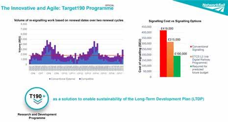
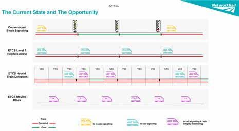
questionnaires with observers present. New assistive tools, specialised train planning tools and microscopic operation simulation tools would be required, all leading to a revised way as to how re-signalling schemes are progressed.
If the increased capacity claim that ERTMS promises is to be realised, then the timetable planning process must also change. The existing tools for timetable compilation are designed for conventional signalling and need to be modified for ETCS operation. Different driver behaviour will emerge and much greater opportunities for ATO should be part of the deliverables. Currently, there is poor integration with the scheme design process.
How then to modernise train operational planning to unlock the full benefits. The work to achieve this is viewed as a three-stage approach:
1. Specify high level targets for F-CCS and from this produce timetable recommendations.
2. From these recommendations, work out the needs of F-CCS and produce a timetabling road map.
3. Undertake a market study to explore how a timetable partner evaluation can be achieved.
These factors are being studied by Birmingham and Delft universities in collaboration with Network Rail and other international rail communities. Feedback from operational experience on the Cambrian Line and the Thameslink central core (both with several years of ETCS operation but very different kinds of railway – one a rural backwater, the other a highdensity urban railway) has proved useful.
The timetabling developments seen as needed must take account of:
» In-cab signalling and resultant higher speeds.
» Full supervision of train movements meaning that trains can run closer together and more flexible use of the track.
» Automated operational control which with ATO leads to greater precision as to a train’s whereabouts.
Three principles then emerge:

A much closer alignment of signal engineers and operators will be needed and, importantly, operators will need to understand what ERTMS can offer. The relationship between systems that provide ETCS technology, traffic management (TMS), driver advisory systems (DAS), train path allocation, rolling stock characteristics, braking performance, routing, platforming, and run times have to be harmonised or even incorporated into a single system.
KPIs would be required and set down during the strategic planning stage. These would lead to different upgrade options, each of which would need to be assessed in line with operators submitting train path requests.
Currently, no such single system exists that is capable of covering these requirements and it will require a collaborative development including industry and innovation partners if one is to emerge. The challenge is considerable as there are so many factors and variables in the requirements list.
Change required
For the UK, the transition to Great British Railways (GBR) will assist in focussing minds but considerable business change will also be needed. It is interesting that in Germany a similar Capacity and Traffic Management system to automate planning and dispatching requirements was put out to industry with the result that no such product existed and thus no offer was forthcoming.
This demonstrates the challenge for industry so, if this article spurs any organisation out there to believe they can offer a solution, I am sure Network Rail (and GBR) would be delighted to listen!
Thanks are extended to Nadia for supplying additional facts and ensuring accuracy of content.
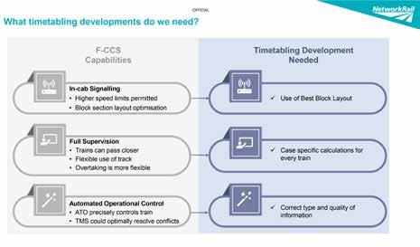
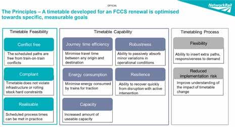
Editor’s note: This article reflects Network Rail’s view as specified in its ‘CP7 delivery plan – Our approach to digital signalling’. However, rolling stock sources and the ‘Signalling Scotland’s Future’ report produced by Network Rail Scotland have a different perspective, particularly in respect of affordability. This difference is explained in our feature “Is ETCS affordable?”

Over the Easter weekend, Network Rail and its supply chain partners successfully completed a diverse programme of work valued at approximately £86.6 million, across 1,190 possessions nationwide.
Major infrastructure renewals and upgrades were delivered across the country, including both asset renewal and enhancement schemes aimed at supporting future network improvements. Of these, 16 projects were classified as RED under the Delivering Work Within Possessions (DWWP) standard, indicating a higher risk of overrun and/or a greater potential impact in the event of delays.
The following pages highlight the tremendous effort and dedication shown by all those involved.
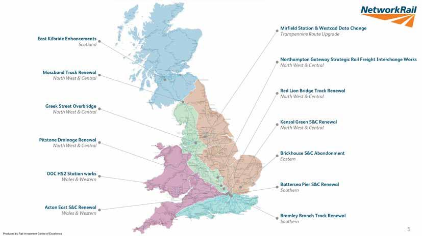

Brickhouse S&C abandonment: Network Rail tasked the South Rail Systems Alliance (SRSA) with recovering the points at Brickhouse Crossover and replacing them with plain line track over two consecutive weekends. This possession facilitated the decommissioning and removal of the disused Brickhouse Crossover, made redundant by the enhanced operational capacity at the new Beaulieu Park station. During the third weekend, the team experienced delays in achieving key milestones after the worksite was handed over approximately an hour later than scheduled. This was due to a signaller routing error. Further delays arose as the fine lining of sleepers took longer than expected. These issues were documented in the duty manager’s report and milestone times were revised accordingly to reflect the on-site conditions. Despite the delays, there were no concerns about meeting the scheduled handback, as the team was confident in recovering lost time during top stoning and tamping operations — a goal they successfully achieved. All planned works were completed, and the site was handed back on time with no outstanding issues.
Mirfield Station & Westcad data change: As part of the Transpennine Route Upgrade (TRU), significant works were undertaken at Mirfield Station to enable the commissioning of a new station concourse and temporary
Platform 1. The project included a Category 6 renewal of 748 metres of track, along with the slewing of the Down Slow line to a temporary position. A 170-metre formation dig was carried out at either end to facilitate tie-ins. Other works included the installation of station hoarding, signage, lighting, and the removal and replacement of Station Information and Security Systems (SISS) and telecommunication systems.
Signalling enhancements featured a TS11 Westcad data change, Westcad screen amendments, the installation of new signal HM563 and a banner repeater, and the relocation of the Automatic Warning System (AWS). Additionally, a Coach-Based Automatic Selective Door Opening (CASDO) system was installed on the new platform. These upgrades facilitate the demolition of the old island platform and allow for the continued construction of the new island platform behind hoarding, ahead of the full station opening at Christmas.
Northampton Gateway SRFI: Northampton Gateway Strategic Rail Freight Interchange (SRFI) is a third-party funded project for the client Segro PLC, including associated track, signalling, electrification and plant, Overhead Line Equipment (OLE), earthworks and drainage, civils and telecoms enhancement, and new works. The scheme will renew the signalling
Mirfield Station Upgrade.
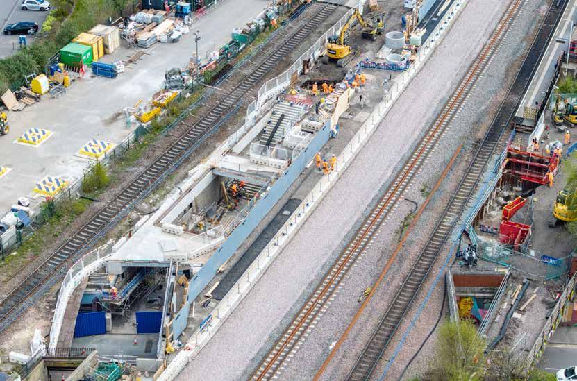
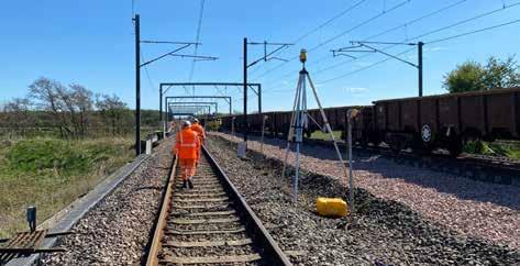
equipment controlled by the Rugby Signalling Control Centre (SCC), Northampton Panel. It will also see the introduction of a new sidings depot accessed via two new crossovers located on the Hanslope Northampton and Rugby Line (HNR). When at full capacity, the depot will handle 16 trains per day, supporting the Network Rail strategy for freight growth.
The project was commissioned over weekends 3 and 4, bringing into use previously installed infrastructure. The project included 22 new AZLM axle counters, signals and points on the HNR Lines; installation of telecoms infrastructure; Rugby SCC Northampton panel data change and VDU updates; a Solid State Interlocking (SSI) Data Change; and the introduction of new depot sidings and the interface between the SSI data and the Tiefenbach data system to control the new signalling system within the depot.
Pitstone Drainage renewal: 196 yards of drainage was installed in the six foot between the fast lines of the London Euston to Rugby Trent Valley Junction line (LEC1) over a 29-hour possession. This included 182 metres of new drainage pipes and five concrete catch pits surrounded by new ballast and pea shingle. The site was then tamped to ensure consolidation of the track before reopening to the passage of trains.
This was the second of two weekends of work on this renewal which will improve the drainage around the crucial fast lines in this busy
section of railway. The improved drainage will increase the longevity and performance of the track going forward. The team will revisit over weekend 6 when 200 yards of drainage will be installed on the slow lines.
During the works, four machines at Cheddington Station were broken into and lifting chains, hooks and around 3,000 litres of diesel were stolen. This delayed Road Rail Access Point (RRAP) installation and drainage works until attachments could be replaced. Despite this, all planned works were completed with a comfortable right time linespeed handback.
Mossband track renewal: This project was based around a conventional renewal with a track stand-down period to allow the subcontractor to complete waterproofing works. The scope included a Category 11 rerail, resleeper, and reballast operation, covering a total renewal length of 0.43km. The works were successfully delivered within a 51-hour possession of the West Coast Main Line over the Esk Viaduct. During this time, ballast, sleepers, and rail were replaced on the Up line between 6 miles 894yds and 6 miles 1360yds – a total of 466 yards. Waterproofing was completed on the bridge deck between 6 miles 948yds and 6 miles 1271yds, covering 323 yards. One minor incident occurred when a Road Rail Vehicle (RRV) accidentally knocked over a tripod, which struck a staff member causing an injury to their nose.
Red Lion Bridge track renewal: This work saw a 400 yard Cat 14 (Rerail, Resleeper, Reballast, Formation) renewal on the busy LEC1 Up Fast line over a 31-hour possession. The works strategically targeted ongoing asset condition issues to enhance performance on this key route.
All planned Cat 14 renewal works were completed with a right time handback. The site was fully welded and the 60mph Temporary Speed Restriction (TSR) handback was achieved.
Kensal Green S&C Renewal: This project involved the formation renewal of NR60 Mk1 C Crossover 2324A&B and Turnout 2325A, incorporating High Performance Switch System (HPSS) Mark 2 Point Operating Equipment (POE). Additionally, 250 metres of new plain
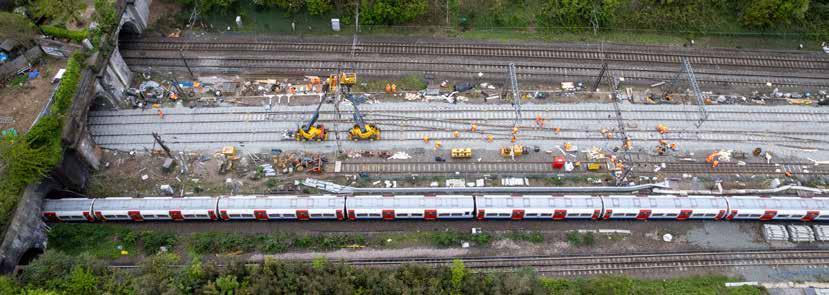
line were installed, and heavy refurbishment was carried out on Turnout 2325B, including the installation of a new full set of switches and conversion to HPSS Mark 2 POE.
All works were completed as planned, with no accidents or incidents recorded during on-track activities. The site was fully welded, stressed throughout, and successfully handed back at the full line speed of 75mph. One off-track incident occurred during the unloading of speed boards from a van, resulting in a minor eye injury to a member of staff. This did not result in any lost time and has been noted as a lesson for future manual handling practices.
Greek Street Overbridge Replacement: The Easter workscope served as a critical enabler for the upcoming August Bank Holiday works, which will involve the removal and replacement of the Greek Street Overbridge – a 53 metre by 27 metre twin-span structure supporting a major roundabout in Stockport. The primary aim of these preparatory works was to facilitate the future bridge replacement, as the existing structure has reached the end of its service life.
Key activities completed during the four-day blockade included upgrading the overhead electrification system; saw cuts at all four corners of the wing wall and breakdown; deconstruction of the bridge including road parapet removal; and 80 core drillings to a depth of three metres on the abutments.
While the main scope was successfully delivered on time, no opportunity works were completed during this phase.
The Battersea Pier S&C renewal: This work addressed a life-expired layout comprising points 725, 726A/B, 727, 729A/B, and 730, where deteriorating components necessitated a full renewal. The layout was renewed like-for-like with a POE upgrade to In-Bearer Clamp Lock (IBCL) as well as retaining HW2121’s for two point ends. The layout was installed in panel form and due to be fully welded together with Modular tie plates with long bearers under the associated crossing within the modular tie area. Interfacing with structures, part of the layout was installed with Delkor Basle plates on composite sleepers to aid the stiffness transition on and off the structure (Spicers Wharf bridge).
Some challenges were encountered, including public interface concerns due to track materials passing debris netting on Spicers Wharf bridge, misalignment between the lead times for bespoke Delkor base plates and the design programme, and cable management issues on site caused by space constraints.
Bromley Branch Track Renewal: Works Delivery London Bridge successfully completed a 38-chain track renewal of all three main track components (sleepers, rail and ballast), during
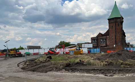
a 72-hour Easter blockade between Grove Park and Bromley North. The works included the full renewal of all track components within the worksite limits; the installation of new sleepers, rails, ballast and breathers at the London end of the site; and the full tamping of the renewal length to restore geometry and ensure compliance with alignment and ride quality standards.
All works were delivered on time, safely, and to the specified quality standards.
Acton East S&C Renewal: The project at Acton East Junction involved a Cat 71 full renewal of six point ends (8120 A&B, 8121 A&B, and 8122 A&B) with HPSS Mark 2 Point Operating Equipment (POE). The scope also included associated OLE adjustments and the relocation of signal SN6131 to accommodate an enhanced track layout.
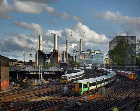
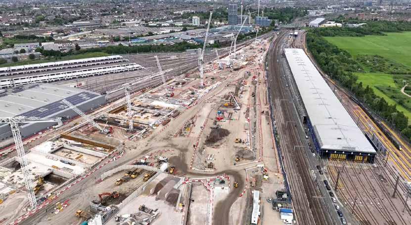
The renewal supports the Poplars Electrification scheme through improved track alignment. All planned track renewal works were successfully completed, with points 8122 A&B installed and commissioned, alongside the completion of signalling and OLE modifications. However, testing and commissioning for points 8120 A&B and 8121 A&B were not completed during the initial possession. Access was later granted for Midweek 6 for Week 4 to complete these outstanding tasks.
The possession overran by two hours and 42 minutes (handback at 07:42 vs planned 05:00). The signalling design at Acton East was found to be incorrect and this is being reviewed as a matter of urgency by the Programme Engineering team. This is a priority area of focus and has been escalated for response within senior levels of the South Rail Systems Alliance (SRSA) and the wider AECOM organisation. There are also improvements being implemented in respect of DWWP compliance and overall deliverability readiness.
Old Oak Common HS2 Station Works: This project involved a range of OLE, signalling, and E&P works to support increased rail traffic capacity into Old Oak Common station and the future HS2 route. Key OLE activities included sealing-end changeovers and recoveries, installation of Auto Transformer Feeder (ATF) cables to the new J05/34A position, cable jointing, pressure testing, and section proving. In the S&T scope, a new foundation for signal SN171 was constructed using two six-foot auger concrete piles, alongside the installation of 140 metres of linear drainage in 30-metre sections. The signalling and E&P works included the installation of a new Up Relief Cess Functional Supply Point (FSP) cable, limited to cable pulling with no terminations. A new signalling trough route was also installed at the western end of the site. In addition, mast and boom installations were planned on the retaining wall structure at the Down Poplars Cess / Up Relief Cess location.
All HS2 planned works were successfully completed except for the mast and boom installation, which was deferred due to the overrun of the Acton East S&C renewal. Lessons learned are to be linked with the Acton overrun review.
Of the planned 1,190 network-wide possessions that took place between 18 and 21 April, 17 service-impacting possession overrun incidents occurred. The most significant possession overrun involved a Capital Delivery S&C track renewal at Acton East Junction, where issues were encountered with the initial dig followed by further signal testing issues. This resulted in 5,267 minutes of delay to passengers of 14 train operators and three freight operators. However, given that the total number of possession overrun delay minutes incurred was 6,160 minutes across 17 incidents, and the total number of booked possessions (at T-0) across the wider business was 1,190, this represents a successful possession handback rate of 98.6% –only slightly below the regularly-achieved 99% right time handback rate.
Over the Easter weekend, there were a total of two reported incidents, both of which were accidents. Neither was classified as a lost time injury.
Both accidents occurred on worksites delivering a major ‘red-ranked’ scheme. The accidents took place at Mossband Track Renewal and Kensal Green S&C renewal.
The dedication shown by staff working over Easter to improve the safety and reliability of the network is a testament to the professionalism of the entire rail industry. We extend our sincere thanks to everyone who gave up their time during the holiday period.





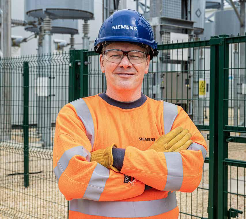
SIEMENS MOBILITY
We understand that collaboration across the rail industry is crucial for reducing cost and driving transformation.
siemens.co.uk/mobility