by rail engineers for rail engineers
STRUCTURES & INFRASTRUCTURE
STRUCTURAL FAILURE AT YARNTON PG.30
SIGNALLING & TELECOMS
BIRMINGHAM NEW STREET
Explore the work to upgrade signalling and control in the area around New Street station.
PHASE 7: OPEN HEART SURGERY PG.42
www.railengineer.co.uk
LEVEL CROSSING & TRACKSIDE SAFETY PG.12
LEVEL CROSSING
SAFETY PG.60
Among the safest in Europe, Great Britain’s level crossings still pose a risk to the public.
2024 – ISSUE 207
MAR-APR
RAIB releases its report into this collapsed wing wall which was struck by a train.
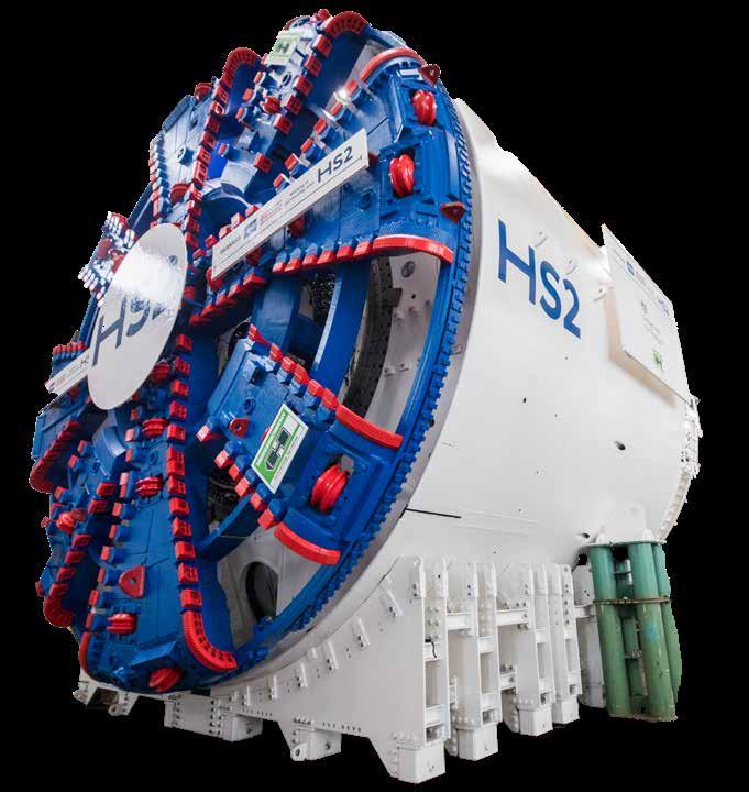
FOCUS: HS2’s ENGINEERING PHOTO: HS2
Train operations
Freight safety
Public behaviour
Passenger operations
Health and wellbeing
Passenger and staff assaults
Occupational health and safety
Level crossings
Fatigue
Safety and health: Asset integrity
We’re with you every step of the way

Leading joined-up thinking to support safer, smarter rail
Britain’s rail network originates from an industry with a uniquely collaborative culture – and every inch is underpinned by dedication to safety and health. But the network’s complexity means we can only get the full benefits of everyone’s safety when we join up the different areas of collaboration, to see the whole system. This lets rail direct its resources to where they’ll do the most good.
T he new Rail Health and Safety Strategy will lead us in this direction. Drawn on detailed consultation across the industry, and led by industry risk groups, it has been designed by industry, for industry.
Discover RSSB’s role in unlocking whole-system solutions. Read the new Rail Health and Safety Strategy: www.rssb.co.uk/thestrategy

42
64
30| 34|
42| 38|
46|
50|
12| 14|
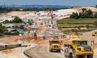
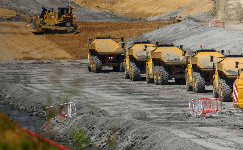
HS2 update: Overview
HS2 hits peak construction this year, with work in motion and a workforce of 30,000 at 350 active sites.
HS2 update: Tunnels
With 104km of tunnelling underway on a scale never seen in the UK, HS2 remains Britain’s largest infrastructure project.


72 CONTENTS
Sekisui’s FFU: Newark flat crossing four years on Newark flat crossing is yet another example of the application of FFU technology on Network Rail infrastructure.
Gripple SwiftLine Rail Dropper
Recently approved by Network Rail, this new dropper changes the game for OLE maintenance and repair.
Birmingham New Street Phase 7: Open heart surgery in the Midlands
Paul Darlington reports on the work to upgrade signalling and control in the area around New Street station.
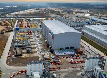
Siemens Mobility boost for Chippenham
Clive Kessell probes the decision making behind Siemens Mobility’s £100 million investment into the building of new premises.
Cyber security in rail
Protecting data and systems remains a low priority in rail and instances of hacking occur all too frequently.
54| 22|
HS2 Structuresupdate:and earthworks
Over 50 viaducts and a huge amount of earthworks are required to create Britain’s first domestic high-speed railway.

Company profile: GGP Consult
Consulting engineering firm GGP Consult provides resources and expertise to over 50 countries around the world.
56|
60|
64|
68|
72|
National Railway Museum inspires future engineers
The UK has an impressive railway engineering heritage and the National Railway Museum attracts over 650,000 visitors each year.
Level crossing safety
Great Britain’s level crossings are among the safest in Europe but still pose a significant risk to the public.
Improving level crossing safety using technology
Paul Darlington reports on how technology can deliver new engineering solutions and improve level crossing risk management.
Getting the on track experience
The ‘Practical Track Challenge’ run by the PWI gives officebased professionals an understanding of track work.
Ayr hotel fire closes railway for eight months
David Shirres reflects on the fallout of the recent fire at Ayr station hotel and considers the building’s future.
14
Structural failure at Yarnton
Mark Phillips examines the RAIB’s report into the collapsed wing wall which was struck by a train at Yarnton.
PHOTO: SIEMENS MOBILITY
PHOTO: DAVID SHIRRES
Rail Engineer | Issue 207 | Mar-Apr 2024 3
PHOTO: ISTOCK.COM/SOLSTOCK PHOTO: HS2


We make no apologies for returning to the subject of HS2 which was cut back as it “no longer reflected post-lockdown changes in travel”. Yet, as Matt Atkins describes, recent ORR figures show a trend of increasing rail passenger numbers. The last quarter’s 21% increase brings journeys up to 90% of the prelockdown levels. Cancelling HS2 phase 2 is apparently not a problem as the Network North proposal claims to double West Coast Main Line capacity to 250,000 seats a day, yet the reality is that it now offers little benefit north of Birmingham. It is not unreasonable to expect that the basis for figures used to justify major policy announcements should be made public, yet the Department for Transport (DfT) refuses to divulge how this HS2 capacity figure was derived. Readers can draw their own conclusions as to why this should be the case.
HS2’s former chief engineer, Andrew McNaughton once described HS2 as the work of generations. He was right to do so, though it will be more generations than he first thought. The problems that HS2 was to resolve have not gone away.
Years of work developing HS2 produced a solution that is unlikely to be much different from that developed by others trying to solve the same problem. Though it will take decades, it is quite possible that the full HS2 Y network will eventually be built. In the meantime, a huge amount of work is being done to construct HS2 phase 1. There are many reasons why this is an expensive railway. One is overheads and procurement arrangements from which lessons must be learnt. Parliament has also willed expensive environmental mitigation such as green tunnels which cost three times more than cuttings. HS2’s route requires costly engineering. Its 47km leaving London and 15km into Birmingham is almost all in tunnels or on viaducts, while its complex Delta Junction has 13 viaducts. High levels of construction inflation have also added £10 billion to HS2’s 2019 estimate.
UK Rail passenger journeys (millions)
In this issue we focus on the project’s impressive engineering and describe how innovative techniques are delivering cost reductions. This includes reusing millions of cubic metres of sometimes contaminated earthworks on site. We explain the bio-remediation of spoil from the derelict Washwood Heath site and how CL:AIRE and DIGGER enabled 26 million tonnes of spoil to be reused, avoiding the need for large numbers of HGV movements. The caterpillar shape of the Victoria Road crossover box also reduced the excavations required. There were also cost savings from constructing viaducts with all major components manufactured off site for HS2 which is a UK first. Another first for HS2 is the double composite design of some of its viaducts whose benefits we describe.
HS2’s 104km of tunnelling is a logistical exercise of feeding tunnel boring machines (TBMs) with concrete segments and removing their spoil. We describe the deployment of these machines to explain why the Northolt tunnels need four TBMs and how TBM Dorothy’s cutterhead is boring three tunnels.
HS2’s website has a legacy section with 200 papers describing the project’s innovations. A significant HS2 legacy is building a diverse, skilled, and talented workforce across its supply chain, of whom 4% are apprentices. Some of these engineers feature in website video clips where they, quite rightly, proudly explain the engineering for which they are responsible. Despite HS2’s curtailment, hopefully such engineers will be able to support the rail industry for years to come.
2000 200 0 400 600 800 1000 1200 1400 1600 1800 2000 2002 2004 2006 2008 2010 20122014 2016 2018 2020 2022
DAVID SHIRRES RAIL ENGINEER EDITOR DAVID SHIRRES Engineering HS2
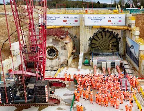
TBM Cecilia’s breakthrough at Chiltern Tunnel North Portal on 24 March PHOTO: HS2 EDITORIAL 4 Rail Engineer | Issue 207 | Mar-Apr 2024
Inspiring future engineers is one of the aims of the National Railway Museum’s masterplan to increase visitor numbers. As we describe, the museum’s new Wonderlab and planned Railway Futures Gallery should encourage young people to engage and get excited by railway engineering.
Developing rail engineers by giving them a safe, practical on track experience is the aim of the Permanent Way Institution’s practical track challenge. As we report, this year 38 participants benefited from this worthwhile initiative which was held at the Bo’ness Heritage Railway in Scotland. The support of all the companies involved has to be acknowledged without whom this event would not have been possible.
Lessons from the collapsed wing wall at Yarnton are described by Mark Phillips who highlights key issues from the Rail Accident Investigation Branch’s report into this incident. These include the need to accurately measure bulges over time and improve structural defect risk scoring. Also at risk of collapse was an abandoned hotel which is closing the railway at Ayr for eight months. We describe why and suggest that there are lessons to be learnt to avoid this situation reoccurring elsewhere.
Birmingham New Street’s 1960s signalling equipment was becoming increasingly difficult to maintain and did not have the flexibility needed to reliably run 1,200 trains a day through its constrained infrastructure. Resignalling the station was done in seven phases over many years. In a comprehensive feature, Paul Darlington explains how the final seventh phase of this project was delivered and the benefits of its various innovations.
The innovations being developed to improve level crossing safety are explained in another feature. Although Britain’s
level crossings are among the safest in Europe, there are many near misses and, sadly, occasional fatalities, particularly at footpath crossings. We explain how Network Rail’s report ‘Enhancing Level Crossing Safety 2019 to 29’ has a strategy to reduce this risk.
With ever greater connectivity, cyber threats present an increasing risk to railway systems. For example, trains were stopped in Poland after hackers accessed an open channel VHF radio. Clive Kessell’s feature shows that this is a complex topic. Yet its key messages are to maintain awareness of this threat and ensure basic precautions are taken.
Rail Engineer was present at the Siemens Mobility press conference in Chippenham when it announced a £100 million investment in new premises which are expected to open in 2026. This will ensure that the company’s skilled local workforce of 800 people will continue to serve the UK signalling market. At this event, Chancellor of the Exchequer Jeremy Hunt advised that the Government will back this plan as part of the UK’s manufacturing revival which will be encouraged by tax reliefs of up to 25%. Unfortunately, tax reliefs were not enough to save the thousands of jobs at Alstom’s Derby plant and its associated supply chain.
The risk to such plants was highlighted in a 2023 Railway Industry Association’s report which warned of the consequences of the hiatus of rolling stock orders. It also called for a long-term industry strategy to create a smoother train order profile. Yet, it is now almost three years since the Williams Shapps report committed to the production of such a strategy. Sadly, the Derby closure is an example of the consequences of the lack of a plan for Britain’s railways.
Production
Production and design
Lauren Palin lauren@rail-media.com
Adam O’Connor adam@rail-media.com
Engineering writers
bob.hazell@railengineer.co.uk
bob.wright@railengineer.co.uk
clive.kessell@railengineer.co.uk
david.fenner@railengineer.co.uk
graeme.bickerdike@railengineer.co.uk
malcolm.dobell@railengineer.co.uk
mark.phillips@railengineer.co.uk
paul.darlington@railengineer.co.uk
peter.stanton@railengineer.co.uk
Advertising
Asif Ahmed asif@rail-media.com
Craig Smith craig@rail-media.com
Rail Engineer
Rail Media House, Samson Road, Coalville Leicestershire, LE67 3FP, UK.
Switchboard: 01530 816 444
Website: www.railengineer.co.uk
Rail Engineer Videos
http://rail.media/REYouTube
Editorial copy to
Email: news@rail-media.com
Free controlled circulation
Email: subscribe@rail-media.com
The

PHOTO: HS2 Editor David Shirres editor@railengineer.co.uk
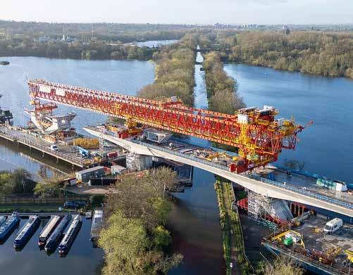
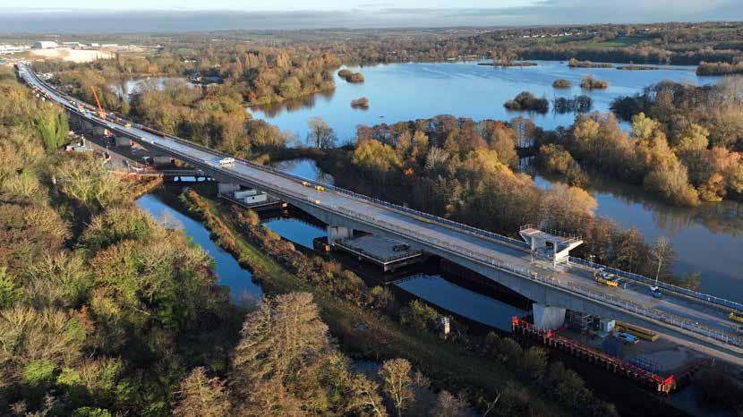
HS2’s Colne Valley Viaduct construction crosses the Grand Union Canal
Editor Matt Atkins matt@rail-media.com
small print Rail Engineer is published by RailStaff Publications Limited and printed by PCP Ltd. © All rights reserved. No part of this magazine may be reproduced in any form without the prior written permission of the copyright owners. Part of: www.rail-media.com THE TEAM 5 Rail Engineer | Issue 207 | Mar-Apr 2024
Passenger journeys on the rise
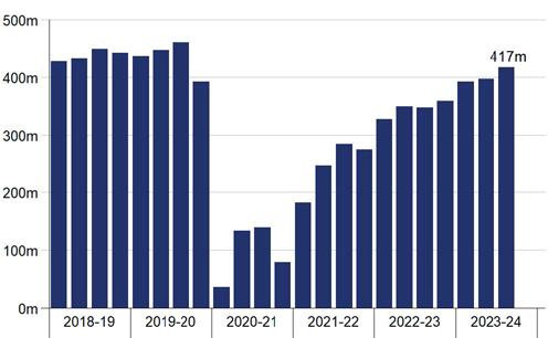
A total of 417 million rail passenger journeys were recorded in Great Britain between October and December 2023, according to the Office of Road and Rail (ORR).
The organisation’s report ‘Passenger rail usage October to December 2023’ shows a 20% increase on the 348 million journeys in the same quarter of 2022. This mirrors the percentage increase for rail journeys for the year January 2022 to December 2023, which saw 1,570 million journeys.
According to the ORR’s report, a total of 15.2 billion passenger kilometres were travelled in Great Britain in Oct-Dec 2023, and total passenger revenue for the quarter was £2.6 billion.
These figures continue to show a rising trend in the recovery from the pandemic lockdowns although the number remains lower than prelockdown levels, at 90% of the 461 million in Oct-Dec 2019.
PASSENGER JOURNEYS
Elizabeth line saw the largest increase in journeys, which were up by 40%, driven in part by the increased number of services following the opening of the central section of the line.
Transpennine Express and Avanti West Coast both planned at least 40% more trains compared with the reduced timetables in Oct-Dec 2022, resulting in a large increase in passenger journeys. ScotRail saw a 34% increase compared with the previous year, but only a 12% increase in trains planned.
Heathrow Express saw the smallest increase in passenger journeys at 5%, followed by c2c and London North Eastern Railway, both up 6%.
Open access operators recorded 2.3 million passenger journeys combined, an increase of 14% on the 2.0 million in the same quarter of 2022.

The report shows that all train operators enjoyed a greater number of passenger journeys. This was due to fewer strike days impacting passenger services than during the same period in 2022.
The report also broke down the statistics by sector. The London and South East sector recorded 293 million journeys in the latest quarter, making it the largest sector. This was a 19% increase on the 245 million journeys in the same quarter in the previous year. The Long Distance sector recorded 34.8 million journeys, an increase of 21%, while the Regional sector recorded 87.7 million journeys, up 22% OctDec 2023.
UK passenger journeys April 2018 to December 2023
ALL GRAPHS: ORR Rail Engineer | Issue 207 | Mar-Apr 2024 NOTICES 6
MATT ATKINS
PASSENGER KILOMETRES
Just over 15 billion passenger kilometres were travelled in Oct-Dec 2023, a 20% increase compared on the previous year. Again, this remains lower than prelockdown levels.
All operators saw a greater number of kilometres travelled during the period. Elizabeth line recorded the largest increase (up 43%), and the smallest increases were shown by Heathrow Express (5%), London North Eastern Railway (6%), and c2c (8%).
Avanti West Coast and Transpennine Express ran reduced timetables in the previous year, which caused a large increase in passenger kilometres compared with OctDec 2022 (both up 39%).
Of the open access operators, Hull Trains, Grand Central, and Lumo, all saw large increases in kilometres travelled (between 23% and 28%).
The London and South East sector recorded 293 million journeys, making it the largest sector. This was a 19% increase on the 245 million journeys in the same quarter in the previous year. The Long Distance sector recorded 34.8 million journeys, an increase of 21%, and the Regional sector recorded 87.7 million journeys, a 22% increase on Oct-Dec 2023.
PASSENGER REVENUE
Total passenger revenue in Great Britain was £2.6 billion in Oct-Dec 2023. Adjusted for inflation, this was 20% more than the £2.2 billion generated in the same quarter in the previous year. Again, this remains below prelockdown levels, at 79% relative to the £3.3 billion in the same quarter in 2019.
Passenger revenue per journey was £6.27, a slight decrease compared with the £6.28 in the same quarter in the previous year.
Passenger revenue per kilometre was 17.2 pence, slightly lower than the 17.3 pence in the previous year.
With a total revenue of £1.3 billion, London and South East remained the largest sector in the latest quarter, though of the three sectors, it recorded the smallest increase in revenue (up 19% on the £1.1 billion in the previous year). The Long Distance sector showed the largest growth with £839 million of revenue in the latest quarter compared with the £694 million in the previous year, up 21%.
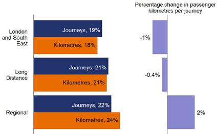
Percentage change in franchised passenger journeys, kilometres and kilometres per journey,
A total of £2.3 billion was generated across all ordinary fare tickets, compared with the £2.0 billion in the same quarter in the previous year. Of these, Advance tickets saw the largest increases (up 26%).
Off-Peak tickets saw the smallest percentage increase (up 15%), with £1.0 million in the latest quarter compared with £897 million in the previous year. Season tickets also generated more revenue in the latest quarter, with £208 million compared with £185 million in the same quarter the previous year (up 13%).
Overall, the change in revenue per kilometre was relatively small across all ordinary fareticket types. Anytime or Peak tickets showed a slight decrease (down 1%), Off-Peak tickets showed a slight increase (up 1%), and Advance tickets showed the least change (up 0.3%). However, season tickets showed a larger change (up 5%).
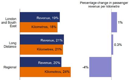
Percentage change
by sector, in Oct-Dec 2023 compared with Oct-Dec 2022
in franchised passenger revenue, kilometres and revenue per kilometre, by sector, in Oct-Dec 2023 compared with Oct-Dec 2022
Rail Engineer | Issue 207 | Mar-Apr 2024 7 NOTICES
TRAIN AND VEHICLE KILOMETRES
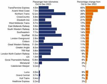
According to the report, Oct-Dec 2023 saw 123 million passenger train kilometres travelled - a 16% increase on the 106 million recorded in the same quarter in the previous year. Passenger train kilometres include only the distance covered by the train itself and so does not account for the number of carriages.
TransPennine Express (up 65%) and Avanti West Coast (up 42%) recorded the largest due to reduced timetables being operated in the previous year. No operators recorded fewer passenger train kilometres compared with the previous year, due to more strike action in the previous year.
INDUSTRY RESPONSE
The report clearly represents a step in the right direction for the industry, but reaction has been mixed. Industry bodies remain concerned that passenger numbers have not yet reached pre-lockdown levels, and that the lack of any long-term strategy will stymy further growth.
A spokesperson for Rail Partners said: “Although the latest ORR data shows an increase in passenger numbers, passengers are still not using trains at the levels seen before the pandemic lockdowns.
“This underlines the urgent need for rail reform to create a new public body to oversee the railways, but also to give operators the commercial freedoms to attract customers back to rail.
“Increasing passenger numbers will grow revenues, reduce taxpayer support, encourage modal shift and help Britain to reach net zero.”
Darren Caplan, chief executive of the Rail Industry Association (RIA) commented: “The return to rail continues apace and this substantial 20% uplift year-on-year is a really encouraging increase in the number of passenger journeys and revenues.
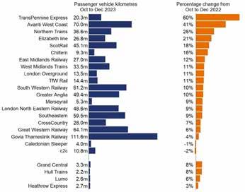
Passenger vehicle kilometres (for locomotive hauled trains this includes the distance travelled by the locomotive) also saw a sizeable increase, with 750 million passenger vehicle kilometres operated in Oct-Dec 2023. This is a 13% increase on the 663 million kilometres in the same quarter in the previous year. However, it remains below pre-lockdown levels, at 92% relative to the 816 million seen in OctDec 2019.
Only c2c and Caledonian Sleeper saw a reduction in vehicle kilometres operated, down 2% and 1%, respectively. TransPennine Express, (up 60%), recorded the largest increase. All open access operators saw an increase, with Grand Central and Hull Trains showing the largest increases (both up 8%).
“These new ORR and DfT figures are a reminder that the railway will need more capacity in the future, especially with the recent RIA-commissioned Steer report forecasting passenger numbers to grow between 37% and 97% to 2050, depending on which policy levers the UK Government adopts in the coming years.
It is clear that there needs to be rail reform and a long-term rail strategy, including a plan for more capacity, to deliver the connectivity, economic, levelling-up, and sustainability benefits everyone wants to see.”
The full report can be viewed here:
 Passenger train kilometres by operator, Oct-Dec 2023, and percentage change from Oct-Dec 2022
Passenger vehicle kilometres by operator, Oct-Dec 2023, and percentage change from Oct-Dec 2022
Passenger train kilometres by operator, Oct-Dec 2023, and percentage change from Oct-Dec 2022
Passenger vehicle kilometres by operator, Oct-Dec 2023, and percentage change from Oct-Dec 2022
Rail Engineer | Issue 207 | Mar-Apr 2024 NOTICES 8
Rail Reform Bill – too little too late
On 20 February, the Government published its Draft Rail Reform Bill. This proposes the creation a new Integrated Rail Body (IRB) that brings together decisions on infrastructure and train operations. The IRB would become Great British Railways (GBR) as proposed in the WilliamsShapps report that was published in May 2021.
This report was the result of the Williams review which was established in September 2018. This in turn was the Government response to the May 2018 timetable debacle which highlighted how, in England, strategic decisions about trains and infrastructure only come together at Westminster.
Reaction to this draft Bill has been largely positive as the principle of GBR being a new strategic decision-making body is welcomed throughout the industry. It is common ground that bringing infrastructure and operational decision making together will tackle misaligned incentives which are the root of many of the railway’s problems and the reason why customer needs are not always put first.
WHY A DRAFT?
It is not clear why only a draft Bill has been prepared. The official reason is that:
NO WISP
A key aspect of the WilliamsShapps report was its proposal that GBR would produce a ‘Whole Industry Strategic Plan’ (WISP) to identify key strategic priorities for the whole rail network over the next 30 years. Although the first such plan was to be published in 2022, to date no such plan has been published.
Having a WISP addresses a weakness of the current structure that no organisation has the financial, technical, and operational authority to oversee the design, investment, and management of the major changes to track infrastructure and on-train systems required for programmes such as decarbonisation and digital signalling.
Yet, in contrast to the emphasis on private finance, there is no requirement for a WISP in the draft Bill, nor does its impact analysis refer to the need for a whole system technical authority.
“Given the scale and complexity of the changes being made to the sector, the draft bill will undergo pre-legislative scrutiny to provide parliamentarians and experts across industry the opportunity to review and test the legislation in draft.”
Yet surely the almost three years since GBR was first proposed should have been sufficient time to do this. Moreover, with a general election looming it could now be 2025 or even 2026 before a Rail Reform Bill becomes an Act of Parliament.
This is because this draft Bill is intended to ensure that GBR maximises private sector input by giving it a statutory duty to produce an annual report on private sector involvement. In contrast, the Labour Party’s plan is for an integrated publicly owned railway. Hence an incoming Labour Government would produce its own Rail Reform Bill which would then have to wait its turn in a crowded Parliamentary timetable.
Hence, whilst it is good to see proposed legislation to progress the formation of GBR, producing a draft Bill which does not have cross-party consensus adds years to the rail reform timetable. It is also disappointing that the engineering benefits of a whole system technical authority do not now seem to be recognised.


 DAVID SHIRRES
Draft Rail Reform Bill - gov.uk
Rail Engineer | Issue 207 | Mar-Apr 2024 9 NOTICES
250,000 seats a day on the WCML?
In the Parliamentary debate on the cancellation of HS2 phase 2, Transport Minister Mark Harper claimed that what remains of HS2 will deliver “a massive increase in capacity to the West Coast Main Line (WCML)” by providing 250,000 seats a day. This figure was subsequently repeated by the Prime Minister and Rail Minister who advised that it applies “across the primary long-distance operator on the West Coast.”
Yet without HS2 phase 2a, there is to be no WCML capacity increase north of Lichfield. Furthermore, with no HS2 station in Manchester it will not be possible to run the planned two-unit 400-metre HS2 trains to the city. Instead, there can only be single 200-metre unit HS2 trains which are
shorter than the current 265-metre Pendolino trains.
Furthermore, 250,000 seats a day is equivalent to running 17 x 605-seat Pendolinos an hour, 24 hours a day. This is clearly not credible.
ESTIMATING WCML HS2 CAPACITY
The table below estimates minimum and maximum capacity increases from HS2 phase 1. It shows a massive capacity increase between London and Birmingham with little benefit north of Birmingham unless all HS2 Manchester trains have a Liverpool portion and stop to split at Crewe. For many reasons, including an additional 10-minute journey time, this is a far from ideal arrangement.
Shadow Transport Minister Stephen Morgan has twice asked Rail Minister Huw Merriman to provide the evidential basis for the claimed 250,000 seats per day for HS2 phase 1. In neither case did he receive an answer. Since November, your writer has also unsuccessfully been trying to obtain the basis for these figures by pursing various stages of a Freedom of Information (FOI) request.
After the DfT press desk refused to provide this information, I submitted an FOI request in December. In January I was advised that more time was needed to consider my request as “a complex public interest test needs to be carried out to determine whether the information should be disclosed.”
ASSUMPTIONS:
1. Current WCML capacity north of Lichfield - 8 x Aventi; 1 x West Midlands and 4 x freight train paths.
2. HS2 offers no WCML capacity increase north of Lichfield.
3. Max capacity: Old Oa Common - 8 tph; Euston - 10 tph.
4. 400-metre-length trains north of Birmgham: Min - 1tph to Edinburgh/ Glasgow split at Crewe; Max - as Min plus 3 tph to Liverpool/ Manchester split at Crewe.
5. Trains operate at this average rate of 14 hours per day.
KEY
TPH: Trains per hour
SPT: Seat per train
SPH: Seat per hour
WCML Passengers per houraverge hourly service Present With HS2 phase 1 - Minimum With HS2 phase 1 - Maximum TPH SPT SPH HS2 from OOC % increase HS2 from Euston % increase TPH SPT SPH TPH SPT SPH Birmingham Pendolino 3 607 1821 2 607 1214 2 607 1214 1 x HS2 unit 3 1100 3300 3 1100 3300 Total 3 1821 5 4514 148% 5 4514 148% Other WCML Pendolinos 7 607 4249 2 607 1214 0 607 0 Voyager 1 200 200 1 200 200 1 200 200 1 x HS2 unit 4 550 2200 3 550 1650 2 x HS2 unit 1 1100 1100 4 1100 4400 Total 8 4449 8 4714 6% 8 6250 40% Grand Total PAX per hour 6270 9228 47% 10764 72% Total seats per day 87780 129192 150696
Rail Engineer | Issue 207 | Mar-Apr 2024 NOTICES 10
DAVID SHIRRES
It was considered that my request was subject to FOI Act clause 35 (1) which enables requests to be refused if the information requested relates to policy in development (i.e. the HS2 timetable) as disclosing it would detract from the time and space required by ministers and officials to develop policy options. The public interest of giving ministers such space must be balanced against that of letting the public understand how the capacity numbers were derived.
PUBLIC INTEREST TEST
In February, my FOI request was refused on the basis that the public interest is best served by not divulging this information. Yet, although it is perfectly reasonable to keep possible policy options confidential until they have been announced, my request was not for policy options (i.e. possible HS2 timetables) but for the baseline capacity information needed to derive such timetables.
For this reason, I requested an internal review of this decision and also referred to FOI clause 35(2) which states that once government has decided a policy, any statistical information used to provide an informed background is no longer subject


to FOI clause 35(1). Hence, the 250,000 seats a day figure used to justify the cancellation of HS2 should be exempt from clause 35(1).
On 22 March, I received a four-page letter explaining why it was not in the public interest to divulge the information I requested. Amongst other things, this letter advised that the 250,000 seats a day figure was not considered to be statistical information mentioned in clause 35(2) as “some of the information underpinning the assumptions and calculations used to derive the seat capacity is derived from comparable assumptions, estimates, and other judgements and opinions rather than being traceable back to factual data.”
This seems to substantiate my view that 250,000 seats a day was a guess. As shown by the table on the previous page, this is not a complex calculation.
FOI clause 35 is a dry subject, and so it is to be hoped that this explanation of its niceties has not been too dull. Yet this is an important subject as government transparency is in the public interest. Hence, anyone who wishes should be able to find out how figures used to justify polices have been derived. The public should also have confidence that the data used to develop policies is not uninformed assumptions.


www.railuk.com UK rail news as it happens. Over 15,000 rail articles. Daily email update. Latest rail video. Rail Engineer | Issue 207 | Mar-Apr 2024 11 NOTICES
HS2 update: Overview
The forecast date for initial HS2 services between Old Oak Common and Birmingham Curzon Street is between 2029 and 2033. Although this may seem some time away, this year HS2 hits peak construction with work well underway and a workforce of 30,000 at 350 active sites.
This work is being delivered by four main works contracts for which stage 1 is design and development and stage 2 is delivery and execution. In 2017, stage 1 of these contracts was awarded as shown below.
In April 2020, a ‘notice to proceed’ to stage 2 was issued to the companies concerned. This enabled construction work to formally start in September 2020. After almost three-and-a-half
SCS
Align JV comprising Bouygues, Volker Fitzpatrick, and Sir Robert McAlpineC
EKFB comprising Eiffage Genie Civil, Kier Infrastructure and Overseas Limited, Ferrovial Construction, and BAM Nuttall
BBV
years, work has begun on two thirds of HS2’s viaducts, over half of its bridges, and a third of the tunnelling has been completed.
With its civil engineering now well advanced, this year will be HS2’s peak construction year. 2024 will also see the award of contracts for the installation of track, signalling, and overhead line work. Although the HS2 route is now one long building site, it will not be that long before it starts to look like a railway. Yet before then there is still much complex civil engineering work to be done. HS2 has been described as a ‘project of megaprojects’.
Readers are invited to judge the truth of this statement for themselves as Rail Engineer provides an overview of HS2’s tunnels and viaducts.
Chilton tunnel southern portal - May 2023
Colne Valley viaduct – December 2023
PHOTO: HS2
PHOTO: DAVID SHIRRES
Area Chainage (km) Includes Let to joint venture South 0 to 25.8 Euston,
DAVID SHIRRES
Northolt tunnels
Colne
comprising Skanska Construction (UK) Limited, Costain Limited and STRABAG AG Central 25.8 to 47.5
viaduct, Chiltern tunnels
Central 47.5 to 125.7 Chiltern
north
Long
Wood
tunnel
portal to
Itchington
south portal
North Everything north of 125.7 Long
Itchington Wood tunnel, Delta Junction, Bromford tunnel, Birmingham approaches viaducts
is a joint venture between Balfour Beatty and VINCI
Rail Engineer | Issue 207 | Mar-Apr 2024 12 STRUCTURES & INFRASTRUCTURE

THE ROUTE
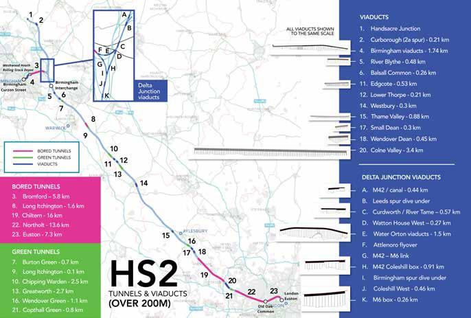
Without doubt, the most complex and expensive part of HS2 is from Euston to the Chiltern tunnel’s northern portal. Of this 47.2 route km, only 6.1km is on open ground as 37.7km is tunnels and 3.4km is the Colne Valley viaduct which will be Britain’s longest railway bridge.
The 109.5km from the Chiltern tunnel to the HS2’s Interchange station in Solihull is primarily through open countryside. This stretch has 22 viaducts of which five are over 300 metres long. They are Wendover Dean (450 metres); Small Dean (315 metres); Thame Valley (880 metres); Westbury (320 metres); and Edgcote (515 metres). To preserve the ancient woodland above it, a 1.7km tunnel has been bored under Long Itchington Wood. This part of the route also has five cut and cover ‘Green’ tunnels totalling 7.1km. It also has two railway crossings. A new bridge carries the new East West rail line over HS2 at Calvert (80.1km). Another bridge takes HS2 under the Coventry to Leamington Line at Kenilworth (142.2km).
HS2’s Delta Junction is immediately north of its Interchange station in Solihull. The Delta Junction has grade separation at its three junctions and is made up of embankments, cuttings, and a total of 13 viaducts taking high speed tracks over motorways, local roads, existing rail lines, rivers, and floodplains. The viaducts include six precast segmental viaducts, four composite viaducts, and three low viaducts.
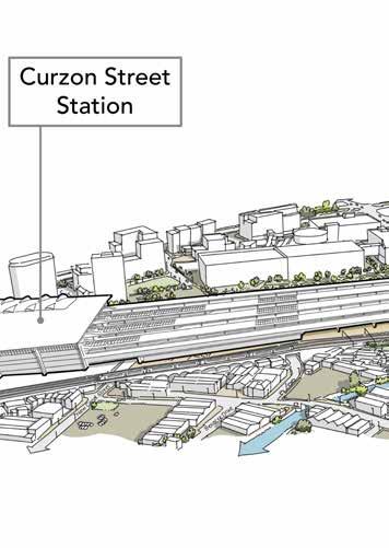
Immediately after the Delta Junction, the 11.3km Birmingham spur starts with the 5.8km long Bromford tunnel which emerges at the eastern end of the Washwood Heath train maintenance depot. The spur is on a series of viaducts 1.7km long, immediately before it terminates at Curzon Street station 175.68 km from Euston.
Going north, the planned flyover over the Leeds spur (166.4 km) is 2km beyond the Delta Junction. Whether this will remain as passive provision is not known. Beyond that, HS2 again crosses the M42 on a box structure. From there, HS2 generally runs through open countryside to a point north of the city where a flyover was planned for HS2 phase 2a (185.8km) which now may well not be built. HS2 phase 1 ends at Handsacre junction 192.77km from Euston.
As at the start of 2024, 45km of tunnels have been dug and work is underway on two thirds of the project’s viaducts and over half of its bridges. The project is currently an unsightly building site passing though some areas of natural beauty. Yet by 2025, most of its civil engineering will be completed and a start will be made installing track and other railway systems.
The bare earth of the project’s excavations will then start to be covered by grass and vegetation. HS2 will then start to look like a railway and blend into the countryside as all railways do.
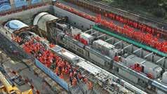
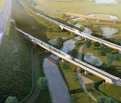
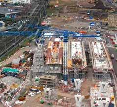
PHOTO: BASEMAP FROM HS2
PHOTO: HS2
PHOTO: HS2 PHOTO: HS2
Curzon Street Station construction site – January 2024
Delta Junction visualisation at Coleshill
Launch of Northolt Tunnel Boring Machines from South Ruislip - October 2022
Rail Engineer | Issue 207 | Mar-Apr 2024 13 STRUCTURES & INFRASTRUCTURE
HS2 update: Tunnels
Of HS2’s 208 route km, 52.2km is in tunnels. There will be 44.3km of twin bored tunnels comprising of Euston (7.3km); Northolt (13.6km); Chiltern (16.0km) Long Itchington Wood (1.6km); and Bromford (5.8km), as well as six cut and cover ‘green’ tunnels totalling 8km. In addition, an 850-metre logistics tunnel in London has been built to deliver materials and remove spoil between Old Oak Common and HS2’s London logistics hub.
This is a total of 104km of tunnelling which is being done on a scale never been seen in the UK. This explains why HS2 is Britain’s largest infrastructure project.
BORED TUNNELS
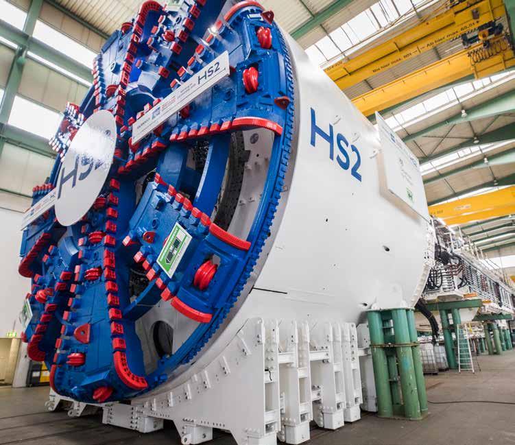
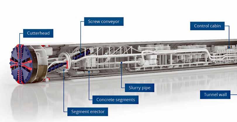
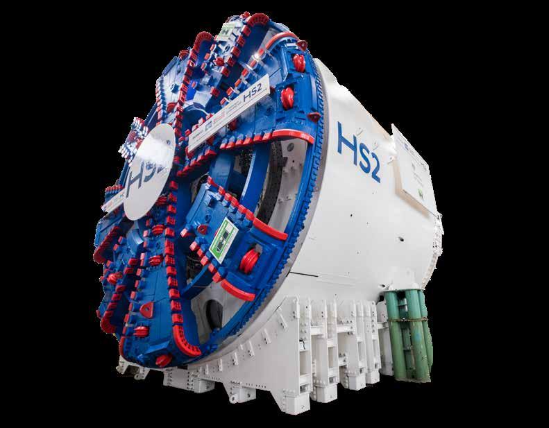
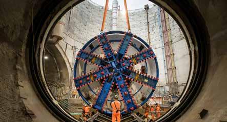
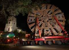
Ten new tunnel boring machines (TBM) have been procured from Herrenknecht to dig HS2’s 10 tunnel bores. These machines are typically 170 metres long, have a cutting head between 8.6 and 10.3 metres diameter and weigh 2,000 tonnes. Different types of TBM employ different methods of supporting the tunnel face during excavation depending on the ground conditions. With significant variation in ground conditions along the route, each one is designed for the specific conditions of its bore. TBMs are not generally redeployed for new tunnelling projects. TBMs typically advance 15 metres per day. Their main components are a rotating cutterhead, spoil disposal system of either slurry pipes or a conveyor, and a tunnel segment erection system.
All have shields to protect the machine until segments are installed. They also require a high voltage supply of typically 10MW. Multi-purpose vehicles (MPVs) run through the excavated tunnel to supply the TBM with concrete segments. The TBMs place seven 35cm-thick tunnel segments to form a 1.9-metre-long tunnel ring immediately behind the excavation. Each segment weighs 8.5 tonnes and has grout injected between it and the tunnel wall. Behind the TBM is a bridge under which a concrete invert is poured to provide a level surface for the MPVs. The TBMs operate continuously and require a crew of around 17 people on each shift to operate them. They have a control room, welfare facilities, and a rescue chamber. TBM personnel took refuge in such a chamber in May 2022 while they waited for smoke to clear after an MPV caught fire in the partly excavated Chiltern bore. The control room monitors the pressure at the cutterhead and the amount of spoil removed compared with the volume excavated.
ALL PHOTOS: HS2
DAVID SHIRRES
Rail Engineer | Issue 207 | Mar-Apr 2024 14 STRUCTURES & INFRASTRUCTURE
A typical TBM


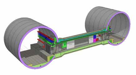
The rings along the alignment are uniform, expect where there is a cross passage between the tunnel bores. Here, strengthened ring segments are needed to allow other segments to be removed for the cross passage. These passages provide an escape route for passengers in an emergency and also house mechanical and electrical equipment.
There are cross passages between the two tunnel bores, 15 to 20 metres long, and every 500 metres. These are dug by a remote-controlled excavator and immediately reinforced by a steel-fibre reinforced sprayed concrete primary lining, after which a sheet membrane waterproofing system and a secondary cast in-situ concrete lining is provided.
The bored HS2 tunnels have ventilation shafts about every 3km. These regulate the tunnel air temperature, extract smoke in the event of a fire, and give emergency services access to the tunnel.
 INSIDE HS2’S LONGEST TUNNEL (YOUTUBE.COM)
BIM model of typical tunnel cross passage section
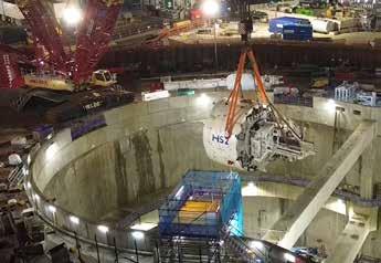
TBM Emily’s cutterhead lowered into the Victoria Road crossover box
INSIDE HS2’S LONGEST TUNNEL (YOUTUBE.COM)
BIM model of typical tunnel cross passage section
TBM Emily’s cutterhead lowered into the Victoria Road crossover box
Rail Engineer | Issue 207 | Mar-Apr 2024 15 STRUCTURES & INFRASTRUCTURE
TBM in the Herrenknecht factory ready for shipping to HS2
A headhouse at the top of each shaft contains ventilation and fire control systems.
HS2 considers that, with the use of TBMs, there should be very little ground settlement from tunnelling operations. Nevertheless, this is an understandable concern for those who may be affected. HS2 is providing all those with properties within 30 metres of its tunnels or other excavations with a settlement deed which records the protection that HS2 provides to the property in a legal document.
EUSTON TUNNELS
Following the government’s Network North announcement in October, it is considering alternative funding arrangements to construct the 7.3km twin bore tunnels between Old Oak Common (OOC) and Euston, which have 14 cross passages and two ventilation shafts.
Nevertheless, the two TBMs required, costing tens of millions of pounds, have already been procured. These are earth pressure balance (EPB) TBMs with a cutting head of 8.5 metres diameter. EPB TBMs operate in soft ground conditions by mixing the excavated material into a paste which is injected into the evacuation chamber behind the cutters so that the chamber pressure balances that of the surrounding soil and groundwater.
This year, these machines will be placed at the end of the OOC station box ready to start excavating the 7.3km tunnel to Euston. HS2 anticipates that this tunnelling will start in 2026. The final fitting out of OOC station cannot be completed until the Euston tunnel TBMs have tunnelled out of the OOC box. Furthermore,
concrete segments are supplied to the TBMs through the OCC box which also receives spoil from the TBMs.
This is possible due to the construction of the Atlas Road logistics tunnel which is another significant cost already incurred to support the Euston tunnelling. This is a 6.2-metre-diameter, 853-metrelong tunnel, from the OOC station box to the HS2 rail logistics hub at Willesden.
The Atlas Road tunnel TBM was one that had been refurbished by Herrenknecht after it had bored two Crossrail tunnels. It was named Lydia, after local school teacher Lydia Gandaa who launched it from HS2’s Atlas Road site in April 2023. It completed its bore by breaking into the OOC box in January.
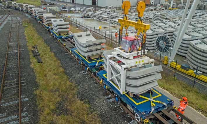
This tunnel services both the Northolt East and Euston tunnels. It will have a conveyor to take the excavated London clay to HS2’s logistics hub when it will be taken by rail for reuse at sites in Kent, Rugby, and Cambridge. Assuming the Euston tunnels are built, over 83,000 tunnel segments manufactured at SRABAG’s Hartlepool plant will be delivered by train to the logistics hub and then through the logistic tunnel to the TBMs.
OLD OAK COMMON TUNNEL
HS2’s shortest tunnel is the 360-metre Old Oak Common tunnel between the OOC station box and the Victoria Road crossover box. Due to its short length and varying diameter at the station approach, this tunnel will be constructed by a cyclic excavation and support method. This uses excavators to dig a short length which is then rapidly sprayed with concrete to stabilise it. Work on this tunnel will start later this year.
Rail Engineer | Issue 207 | Mar-Apr 2024 16 STRUCTURES & INFRASTRUCTURE
First train with segments for London tunnels leaving the Hartlepool factory – December 2023
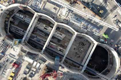
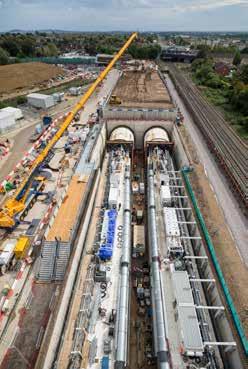
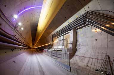
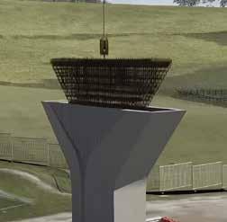
VICTORIA ROAD CROSSOVER BOX
Although this box is an open structure, it is an integral part of HS2’s tunnels. It forms a launch platform for the Northolt tunnel’s TBMs, provides tunnel ventilation, and houses the crossover before OOC station. This has now become a critical asset as it will be used by every HS2 service whilst OOC is HS2’s London terminus.
The box is 130m long, 24-metres deep, and 42-metres wide at its widest point. The initial design was for a rectangular box, though further optioneering developed its caterpillar shape. This reduced the amount of concrete required by 40% and avoided the need for temporary propping during construction.
The Victoria Road Ancillary Shaft has also been built adjacent to the crossover box. This will provide ventilation, emergency access and house signalling equipment. It has an internal diameter of 25 metres, is 25 metres deep, and was constructed with precast rings at the top, with a sprayed concrete lining at the bottom.
Enabling work to clear the 42,000 square metre crossover box site was completed in March 2019. This was done by a Costain Skanska joint venture and involved the demolition of eight buildings from which more than 98% of waste material was sent for reuse and recycling.
The first stage in the box’s construction was the provision of 77 x 44-metre tension piles to support the base slab (i.e. 19 metres below the slab). Reinforcement for the box’s diaphragm walls was then installed into the ground in 70 discrete panels and concrete for these walls was then poured. Excavation of the crossover box was done in three stages. Firstly, there was a 2-metre excavation to install a capping beam and the top props. A further 13 metres was then excavated for the installation of the intermediate row of props, then the final 10 metres was excavated to the level of the base slab. In total 240,000 tonnes of clay were excavated. The 3.3-metre-thick base slab was constructed in three different pours. The first and largest pour was of around 1,000 m3 of concrete. Headwalls of 1.5 metres thick were then built to support the diaphragm wall structure when the TBM breaks through the wall.
NORTHOLT TUNNELS
The 13.6km twin-bore Northolt tunnels face HS2’s most variable ground conditions, with the eastern section being completely bored in London Clay. Yet west of the Greenpark Way ventilation shaft where the TBMs will be extracted, there are gravels, sand, silt, and some quite high-waterbearing areas.
Although the EPB TBMs can deal with such varying ground conditions these tunnels require four TBMs. Two EPB 9.08m diameter shield TBMs are to bore the 5.5km from the Victoria Road crossover box, immediately west of OOC, to the Greenpark Way shaft. The other two TBMs have EPB 9.82-metrediameter shields which will also finish their bore at this ventilation shaft after boring 7.9km from the tunnel’s West Ruislip portal.
The use of four TBMs reduces the tunnelling time by about 12 to 18 months. Also, the eastern part of the tunnel is slower that the western part can be bored at a smaller diameter to reduce the excavated arisings.
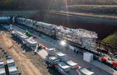
Two TBMs named Sushila and Caroline were delivered to their West Ruislip launch site at the Northolt tunnel’s western portal in December 2021. They were named after local teacher, Sushila Hirani and astronomer, Caroline Herschel. Sushila was launched in October 2022. Caroline started her bore shortly afterwards. At the time of writing, Sushila and Caroline have bored respectively 4km and 3.5km. All four Northolt tunnel TBMs dispose of their spoil by conveyors.
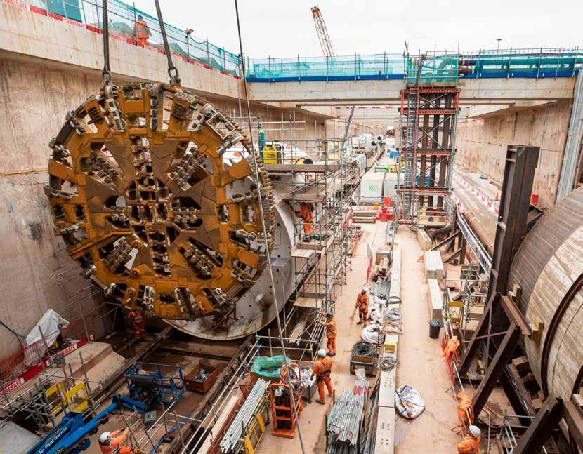
Part of TBM Anne being lowered into the Victoria Road Crossover Box
TBMs Emily and Anne in the Victoria Road Crossover Box ready to start the eastern Northolt tunnels
Rail Engineer | Issue 207 | Mar-Apr 2024 17 STRUCTURES & INFRASTRUCTURE
TBMs Caroline and Sushila at the Northolt tunnel West Ruislip portal prior to their naming
The TBMs that will bore the eastern part of Northolt tunnel have been named after Emily Sophia Taylor, a midwife who became Ealing’s mayor and Lady Anne Byron, an educational reformer and philanthropist. Emily was launched from the Victoria Road crossover box at the end of February. Anne was launched in April.
The Northolt tunnel will have 20 cross passages with fire doors at each end. Construction of these at its western end will require ground freezing and dewatering in view of the soil conditions.
It will have four ventilation shafts from 30 to 40 metres deep. Of these, the Greenpark Way shaft must be built to allow for extraction of the four TBMs. One design constraint was that HS2’s Down line was to be directly under the main line to High Wycombe. During design development, the requirement for HS2 tunnels to be at least one diameter apart was relaxed so that the Down line tunnel need no longer be under Network Rail’s tracks. This allows shafts from both bores at Greenpark Way, with one being a satellite shaft. TBM extraction is possible from both these shafts although the satellite shaft will be capped after the TBM has been removed.
CHILTERN TUNNELS
The 16km-long Chiltern tunnels were almost exclusively excavated in chalk. They are 80 metres below ground level at their deepest point, though are only 20 metres below the River Misbourne, where care had to be taken to monitor and protect the rare chalk stream. The first 200 metres of their long bores passed under the M25 and so necessitated a lot of work with National Highways to get the necessary approval for these bores which resulted in very little ground movement.
Variable density (VD) TBMs with a 10.24-metrediameter cutting face have been used for these bores. VD TBMs have various slurry face support technologies including earth pressure balance. In addition, these Herrenknecht TBMs offer a continuous tunnelling technique with a newly developed centre of thrust system to more effectively maintain the specified alignment.
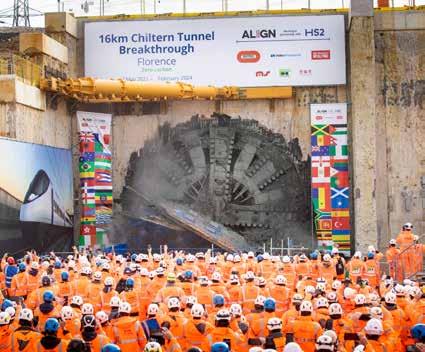
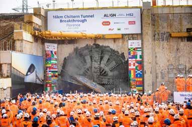
These TBMs are named after founder of modern nursing, Florence Nightingale and astronomer Cecilia Payne-Gaposchkin. Florence was launched from Chiltern tunnel’s eastern portal in May 2021 followed two months later by Cecilia. Florence completed her bore on 27 February. At that time Cecilia had completed 98% of her bore. This is an average excavation rate of 15.6 metres per day, though the record was 44 metres in a single day.
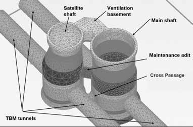
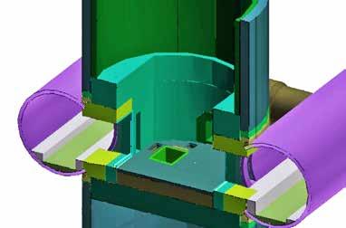
The Chiltern tunnels have 38 cross passages, 10 to 15 metres long, and five ventilation shafts, the deepest of which, at Chalfont St Peter, is 63 metres below ground level. There is a complex interface between the 18-metre-diameter ventilation shaft and the twin 9-metre shafts tunnel bores which are 25 metres apart centre to centre and so intersect with the ventilation shaft walls. There are three openings in the tunnel lining at this point. The largest, for tunnel ventilation, is 5 metres high and 4 metres wide. There are also two service openings for cables.
Arrangement of Greenpark Way ventilation shafts
Florence completing her 33-month, 16km tunnel bore under the Chilterns
Chiltern tunnel bore with cross passage visible to the right
Rail Engineer | Issue 207 | Mar-Apr 2024 18 STRUCTURES & INFRASTRUCTURE
Arrangement of Chalfont St Peter ventilation shaft and Chiltern tunnel bores
The ventilation shaft is built in advance of the tunnel so that the TBMs can advance through its walls which are formed by 1.2 metre thick Dwall panels. After that, openings are formed in the tunnel wall and the access passageways, with required reinforcement, are created.
Unlike the Northolt TBMs, Florence and Cecilia dispose of their spoil mixed with water through slurry pipes. There are also pipes for water to supply water to the TBM as well as conduits for HV electrical cables.
The slurry treatment plant at the south portal produces chalk cake material for use in HS2’s designated landscaping scheme. The plant’s input flow rate is up to 1,250m3 /h per TBM. On average, it produces 2,650m3 of filter cake per day. There was also a temporary pre-cast segment factory at the tunnel portal which produced the 112,000 segments needed for the Chiltern tunnels.
LONG ITCHINGTON WOOD
The 1.6km twin-bore Long Itchington Wood tunnel protects the ancient woodland above it and was excavated through mudstone and clays. A single VD TBM with a 9.92-metre-diameter cutting
face has been used for these bores. This has been named after Dorothy Hodgkin, the first British woman to win the Nobel Prize in Chemistry.
Dorothy was launched at the tunnel’s north portal in December 2021 and completed its bore in July 2022 after seven months. The TBM was then partially disassembled and returned to the north portal. Its gantries were then brought back through the tunnel, whilst nine larger items including the cutterhead (160 tonnes) and tailskin (130 tonnes) were transported by road.
When Dorothy was relaunched in November 2022, it only took four months to complete its second bore in view of the experience gained from the first bore. The 500,000 tonnes of mudstone excavated from both bores was processed at an on-site slurry treatment plant. From there, it was separated out before being transported by a 254-metre enclosed conveyer and used to build embankments along the route of the railway.
Dorothy has since been dismantled and many of her component parts were sent to be reused in the second Bromford Tunnel where the rebuilt TBM has been named Elizabeth.
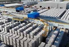


 Tunnel segment factory and yard at Chiltern tunnel’s southern portal
Dorothy about to start her first bore
Tunnel segment factory and yard at Chiltern tunnel’s southern portal
Dorothy about to start her first bore
Rail Engineer | Issue 207 | Mar-Apr 2024 19 STRUCTURES & INFRASTRUCTURE
Dorothy’s cutter head returning to the north portal for its second bore – September 2022
BROMFORD TUNNEL
The 5.8km Bromford tunnel ends 5km from HS2’s Birmingham Curzon Street station. Hence the linespeed through the tunnel (230km/h) is much less than that through Long Itchington Wood tunnel (360km/h). As a result, Bromford is a smaller 8.62-metrediameter tunnel. It is being bored through mudstone with some sandstone.
An 8.56-metre-diameter VD TBM is being used to bore these tunnels. The first one was launched in August and is named after Mary Ann Evans who is better known by her pen name George Elliot. At the time of writing, Mary Ann had bored 1.5km. A second has been assembled using the gantries and the centre part of the cutterhead from Dorothy. This TBM was launched in March and has been named Elizabeth after Dame Elizabeth Cadbury, who spent her life campaigning for the education and welfare of women in Birmingham.
 Dorothy’s cutter head at Bromford about to become part of TBM Elizabeth – December 2023
Rail Engineer | Issue 207 | Mar-Apr 2024 20 STRUCTURES & INFRASTRUCTURE
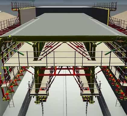
Graphic of formwork used to construct the Copthall tunnel roof
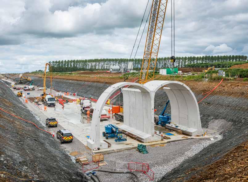
GREEN TUNNELS
Green tunnels are cut-and-cover structures, backfilled above with restored or enhanced vegetation. They shield the local environment and neighbours from the noise and visual impacts of passing rail traffic.
At Copthall, between the Northolt tunnel and Colne viaduct, the HS2 Act specified a deep cutting. However, following a 2018 affordability exercise, it was decided to replace this cutting with a cut-and-cover tunnel. This avoided 400,000 m3 of excavated material and removed the need for off-site disposal of 1.35 million m3 and so has significant programme, community, and environmental benefits. Backfilling above this tunnel also limits long term heave by limiting the unloading effect of the removal of London Clay.
This 600-metre tunnel has a reinforced concrete box structure which is being constructed using innovative wall and roof travelling formwork systems that eliminate the need for formwork cranage. These 40-metre wall and roof travellers also significantly reduce the cycle time for pouring each 20-metre wall or roof sections.
The tunnel design includes several natural ventilation ‘chimneys’ which avoids the need for tunnel ventilation equipment.
North of the Chilterns there will be five green tunnels with a total length of 7.9km: Wendover (1.1km); Greatworth (2.7km) Chipping Warden (2.5km) Long Itchington Wood at the bored tunnel’s south portal (0.1km); and Burton Green (0.7km).
These tunnels are built using a series of M-shaped arches. The arches are made up of five precast units which are 20.4 metres wide, 2.5 metres long, to form two 8.4-metre-high tunnels. At
Chipping Warden and Greatworth these are placed on a 300mm reinforced concrete base slab, at other tunnels this slab is cast in situ. The tunnel is waterproofed using a double layer, compartmentalised membrane system which is placed in position by a bespoke gantry system. The M-arches are then backfilled to the depth required by the local topography. The deepest section, at Chipping Warden, has 18 metres of backfill.
Fire door openings in the centre wall are provided every 300 metres for train evacuation. In common with the TBM tunnels, the green tunnel will have 100-metre-long, progressively porous portals, to reduce noise from the pressure waves as trains enter and exit the tunnels at 360km/h.
TUNNEL LENGTHS
On the UK’s 16,000km rail network the total length of its tunnels is 186km which is around one per cent of the network. Britain’s 19th century railway builders tried to avoid expensive and difficult tunnels which were then generally only necessary to build a reasonably level railway through challenging terrain. Early railway builders generally did not have to contend with a dense built environment.
Those who planned phase one of HS2 faced not only extensive built up areas but environmental pressures to build green tunnels. As a result, of HS2’s 208 route km, 52.2km (25%) is in tunnels. As shown in this feature HS2’s tunnel engineering is impressive, yet tunnelling is an expensive option.
At the time of writing HS2 has completed 46.3km of its 75.9km of bored tunnels. Readers who wish to follow the progress of HS2’s tunnelling can do so at https://tunneltracker.com/
Rail Engineer | Issue 207 | Mar-Apr 2024 21 STRUCTURES & INFRASTRUCTURE
Work starts on the Chipping Warden green tunnel which requires 5,000 tunnel segments
HS2 update:Structures and earthworks
Along its 208 route km, HS2 requires over 50 viaducts of which 16 are over 300 metres long. One of these is the 3.4km Colne Valley viaduct which will soon be the UK’s longest railway viaduct. Less newsworthy is the huge amount of earthworks needed to create Britain’s first domestic high-speed railway.
This update features the Colne Valley viaduct, other viaducts of novel construction, as well as those required for HS2’s delta junction outside Birmingham over the motorway network. It also provides examples of the scale and complexity of HS2’s earthworks.
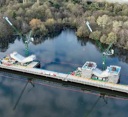
COLNE VALLEY VIADUCT
Between its Northolt and Chiltern tunnels, HS2 crosses the flat Colne Valley which is a mosaic of farmland and woodland with 200km of rivers, canals, and over 60 lakes. A hundred years ago it was not so attractivethe result of the extensive sand and gravel extraction for London’s building boom in the early 20th century. Following this, much of this area was restored as wetlands with lakes up to 400 metres long.
DAVID SHIRRES
All PHOTO: HS2
Temporary bridge and Colne Valley viaduct V piers – May 2023
link road – Feb 2024 Rail Engineer | Issue 207 | Mar-Apr 2024 22 STRUCTURES & INFRASTRUCTURE
Viaduct section moved over M42
M6
HS2’s route across this environmentally sensitive area requires a 3.4km viaduct which has to be blended into this landscape. To do this, its design was inspired by a skipping stone’s flight across the water. The result is a series of elegant spans 10 to 15 metres above the surface. Above the lakes these are up to 80 metres long, whilst shorter 50-metre spans cross wooded areas.
Before piles could be driven to support the viaduct’s piers, over a kilometre of temporary jetties had to be constructed. Cofferdams around each set of foundations were also required as were bases for the tower cranes required at each pier. The viaduct’s 56 piers support a thousand deck segments, each with a slightly different shape due to the viaduct’s gentle curves. Forty-five of these piers weigh around 370
tonnes and sit on concrete piles up to 55 metres deep. They are cast in-situ with special formwork. Eleven V piers support the 80-metre-long spans over the lakes. These 1,800-tonne structures are supported on six 60-metredeep piles which required a 520 cubic metre concrete pour taking nine hours. Due to their complexity a full-sized mock-up was first built to test working practices including formwork placement.
As on other HS2 structures, Ground Granulated Blast Furnace slag (GGBF) is being used as a cement replacement. When it is ground fine, GGBF has good cementitious properties and, when mixed with Portland cement, it provides a strong concrete with a lower carbon footprint. The Colne Valley viaduct is the largest UK use of GGBF.
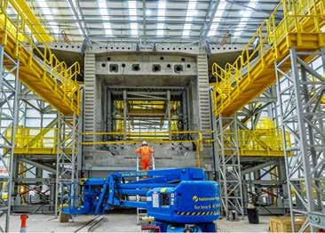
To minimise construction traffic on local roads, the jetties built across the lakes provide a continuous road inside the project. The 140-tonne viaduct segments are made on site at a large purpose-built temporary factory close to the north abutment. This also reduces road movements as does the use of dedicated slipways on the M25 for construction traffic. At peak construction, this factory casts around 12 segments every week using a ‘match-casting’ technique in which each segment is poured against the previous one to ensure the whole deck fits perfectly.
A 700-tonne launching gantry positions the segments. This is 160 metres long, 18 metres high and 18 metres wide. It was originally built in 2004 and had been used in Hong Kong and Singapore. After it arrived in the UK in 49 containers, it took several months to assemble. Prior to its use it had to be assessed against applicable UK standards, including those for wind loading. Using this gantry determined the maximum segment weight and hence the number of segments required.
The gantry has two long trusses with two moveable main and secondary base supports. Between the trusses are trollies and cranes for it to simultaneously place segments either side of a pier. It uses its supports to advance over the already completed bridge deck so that its truss can extend to the next pier. It then positions a single segment on top of this pier on which one of its main supports is then placed.
Single segments are then placed either side of this pier. Props are secured under these segments and the gantry anchored to the pile cap before further segments can be placed. This increases the stabilising lever arm from two to six metres to resist the bending moment from placing further segments away from the piers. These then form an even cantilever either side of the pier. Epoxy is applied to the face of each segment as it is positioned after which the cantilever is temporarily tensioned to compress the epoxy whilst it sets. Once the span’s final segment is inserted, it is post tensioned with permanent steel strands. At peak rate, the gantry can position six segments per day.
The viaduct’s construction began in early 2021 when the first piles were installed. The last of its 292 piles were installed in January 2023. By then, 500 metres of the viaduct had been completed after the launching gantry commenced operation in spring 2022. As of February, over 700 of its 1,000 deck segments have been installed.
The installation of track and railway systems which start after construction of this 3.4km-long viaduct will be completed in 2025. It will then have stolen the title of the UK’s longest railway bridge from Dundee’s Tay Bridge by 100 metres.
First segment produced for Colne Valley viaduct – Feb 2022
Launching girder between Colne Valley viaduct piers 55 and 56 – Nov 2022
Rail Engineer | Issue 207 | Mar-Apr 2024 23 STRUCTURES & INFRASTRUCTURE
Colne Valley segment factory
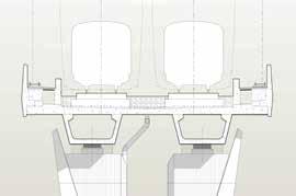
DOUBLE COMPOSITE VIADUCTS
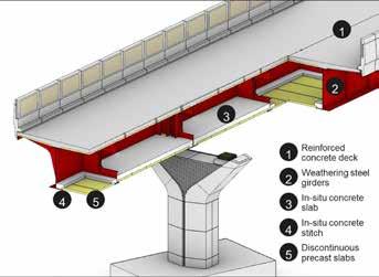
The 450-metre Wendover Dean and 345-metre Small Dean viaducts near Wendover have respectively nine and five piers, giving them average spans of 45 and 57.5 metres. Though successfully used in Europe, these viaducts are two of five HS2 viaducts that are the first in the UK with an innovative double composite design. This is described in an HS2 learning legacy technical paper by Razvan Capra, Pere Alfaras Calvo, and Paul Van Hagen of Acardis/EKFB.
For over a hundred years, steel-concrete composite bridges have been built with a top concrete slab in compression and a steel structure resisting tensile forces. However bending moments over intermediate piers can cause the concrete slab to crack unless there is sufficient steel reinforcement to control the tension forces.
The double composite section design adds a concrete slab to the lower part of the structure around its piers. This reduces the structural steel required by 10 to 15% and simplifies steel fabrication. There has recently been increased interest in this new form of construction as highspeed railway projects benefit from it.
These HS2 viaducts have an in-situ reinforced concrete slab over the pier regions. Outside this area there are precast concrete planks connected by an in-situ stitch pour. This provides increased damping and enhances the superstructure’s torsional resistance. For high-speed rail, this provides an improved dynamic response and limits noise from wheel-track induced vibrations. The resultant closed box section also creates a suitable enclosure for services and drainage.
Although they offer significant advantages, such bridges require additional construction stages for their in-situ concrete slabs and precast planks. They also add to the weight of the superstructure which may require bigger bearings and might slightly increase the viaduct’s cost.
A particular construction advantage is that the deck is launchable and so can be built at ground level and pushed over its piers. This allows the use of more factory-built precast sections and reduces working at height.
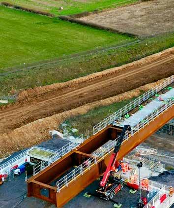
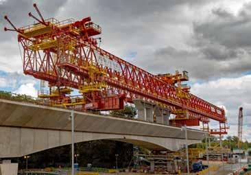
The first bridge slide of the Wendover Dean viaduct took place in January when 90 metres of bridge beam was slid over Teflon pads at nine metres per hour onto its first two piers. Due to its length, the deck is being assembled in three sections with each one pushed out before the next section is attached behind it. The deck’s steel girders are delivered to site in 25-metre lengths which are welded together on the assembly platform. As the deck is slid over, it bends under its own weight. An angled beam fitted to the front of the deck raises it when it reaches the next pier. The piers consist of a stem with a hammerhead on top. The stem is constructed by first installing a steel reinforcement column, then placing a pre-cast shell around it before pouring the concrete. Then, a 50-tonne pre-cast hammerhead shell is placed on top of the stem, a reinforcement cage is lifted into it and concrete is poured into it.
Construction of the Small Dean viaduct is less advanced. This requires piers to be built between the Chiltern main line railway and A413 road which needs to be diverted to accommodate the piers.
 Wendover Dean Viaduct after the first deck beam slide – Jan - 2024
Section view of double composite viaduct
Wendover Dean Viaduct after the first deck beam slide – Jan - 2024
Section view of double composite viaduct
Rail Engineer | Issue 207 | Mar-Apr 2024 24 STRUCTURES & INFRASTRUCTURE
Steel reinforcement lowered into pre-cast hammerhead shell
Other double composite viaducts are being constructed at Westbury (320 metres), Turweston (70 metres) and Lower Thorpe (210 metres).

MODULAR VIADUCTS
The 880-metre Thame Valley and 515-metre Edgcote viaducts have respectively 34 and 20 piers giving them both average spans of around 25 metres, i.e. half that of the double composite viaducts.
These are the first UK viaducts to have all their major components manufactured off site. The Thame Valley viaduct requires 68 x 42-tonne fully formed pier sections and 72 x 97-tonne deck beams together with parapet and ancillary beams. On site, the pier sections
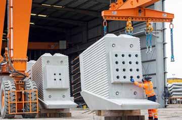
are plugged into their pile caps. Once the beams have been placed on the pier tops, they are braced until the deck slab is cast which is the only substantial in-situ concrete required. After this parapet beams are fitted.
The pretensioned hollow beams are coupled to each other through thickened end walls using post tensioned bars. In this way a continuously tensioned deck is created, with all main elements of the structure always in compression.
As well as improving site safety, the factory production of such enormous parts enables work to be done to millimetre tolerances. This is also expected to save around five months construction time.
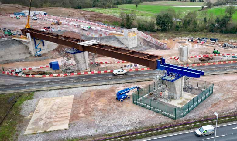
DELTA JUNCTION VIADUCTS
Just north of HS2’s Birmingham Interchange station is the triangular Delta junction where HS2 trains from London will be routed to Birmingham or the West Coast Main Line (WCML). The junction has 10km of HS2 tracks with 13 viaducts crossing a network of motorways, local roads, railways, and rivers.
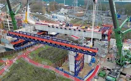
The junction’s west chord has the River Cole east and west viaducts and the M42/M6 link viaducts which had the first part of the first deck slid into position in February. Its full 158-metre composite deck will be positioned in April.
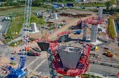
The east chord has Coleshill North and South Viaducts, Watton House viaducts and the River Tame East and West viaducts. The first 39-metre span of the 472-metre River Tame West viaduct was completed in December. The north chord has the separate single-track Water Orton northbound and southbound viaducts which, at up to 20 metres high, will be amongst HS2’s tallest structures. These two 700-metre-long viaducts will be supported on 32 piers, the first of which was completed in August.
 VIDEO OF WESTBURY VIADUCT SLIDE
Completed Thame Valley viaduct piers at Pacadar factory on the Isle of Grain - May 2023
First span of River Tame viaduct in place – Dec 2023
First completed Water Orton viaduct pier – Aug 2023
VIDEO OF WESTBURY VIADUCT SLIDE
Completed Thame Valley viaduct piers at Pacadar factory on the Isle of Grain - May 2023
First span of River Tame viaduct in place – Dec 2023
First completed Water Orton viaduct pier – Aug 2023
Rail Engineer | Issue 207 | Mar-Apr 2024 25 STRUCTURES & INFRASTRUCTURE
Thame Valley viaduct cross section
A total of 153 piers will be built for the Delta Junction’s viaducts. Of these, 15 were completed by the end of 2023. There are three types of viaducts:
» Precast segmental viaducts with 45-metre standard spans (River Tame East and West; Water Orton 1 and 2; Coleshill East and West).
» Composite viaducts having concrete decks and weathered steel structures with standard spans of more than 45 metres (M42/M6 Link Road East and West; River Cole East and West).
» Low viaducts with standard spans of 25 metres with standard concrete deck and precast beams. (M42 Coleshill North and South; Watton House).
A 55,000 sq. m factory at Kingsbury employing 1,000 people started producing concrete viaduct segments in June. This will produce the delta junction’s 2,742 segments which weigh between 50 and 80 tonnes at a rate of eight per day.
INTO BIRMINGHAM
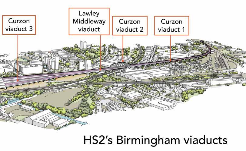
The last two kilometres to HS2’s Birmingham Curzon Street station are on five connected viaducts: Duddeston Junction viaduct; Curzon Street viaducts numbers 1, 2, and 3, and the Lawley Middleway viaduct.
After passing the HS2’s Washwood Heath depot, the line crosses the Derby to Birmingham railway at Duddeston junction on a 370-metre-long viaduct with a 1 in 33 gradient to connect it to the 690-metre Curzon No 1 viaduct which will be 30 metres high where it crosses the River Rea. From this point, the line drops at 1 in 200 to Curzon Street Station.
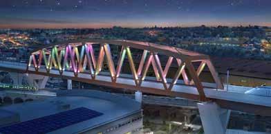
The 150-metre-long Curzon No 2 viaduct has a 25-metre- high truss in weathering steel incorporating dynamic colour lighting. This will be 40 metres above ground level as it crosses the Birmingham and Bushbury railway which is on a 15-metre-high brick viaduct.
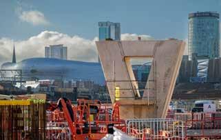
The 213-metre Lawley Middleway viaduct between Curzon No 2 and Curzon No 1 viaducts widens out at its western end for the start of the Curzon Street station throat. The 300-metre Curzon No 3 viaduct is around 5 metres above ground level and widens into four separate decks on V piers to accommodate most of the station throat. This arrangement maximises daylight and space in the public area below. Where it crosses the Digbeth Canal, this viaduct has four inverted steel piers to reference Birmingham’s canal heritage.
 Start of viaduct deck slide over the westbound M42 M6 link roads - Feb 2024
Graphic of completed Curzon No 2 viaduct
Start of viaduct deck slide over the westbound M42 M6 link roads - Feb 2024
Graphic of completed Curzon No 2 viaduct
Rail Engineer | Issue 207 | Mar-Apr 2024 26 STRUCTURES & INFRASTRUCTURE
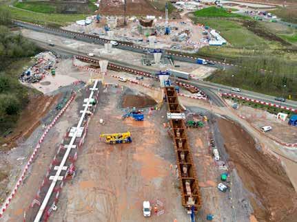
First pier for the Curzon 3 Viaduct – Jan 2023
Work on Curzon No 3 viaduct is well advanced. Its first V pier was completed in January 2023. By November, its first two 90-metre decks and 26 piers had been completed.
EARTHWORKS
Whilst not so newsworthy or visually striking, HS2’s earthworks are a huge undertaking that present significant challenges. Phase 1 requires around 50 embankments of which the longest is at Grendon Underwood which is 3km long and up to 3.5 metres high. Sixty-six cuttings are required, of which the longest is the 4.1km Calvert cutting. The 750-metres-long, 30.5-metres-deep Lower Thorpe cutting is HS2’s deepest. Tens of millions of cubic metres have been excavated to create HS2’s cuttings of which 95% were reused on site.
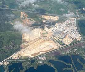
Work to prepare the 65-hectare site at Washwood Heath for HS2’s train maintenance depot and control centre was completed in December. This heavily contaminated derelict site required over a million cubic metres of excavations which included rubble from demolished car factories and other industrial plants. Excavations were up to seven metres deep and were remediated by screening and bioremediation to remove oils and fuel contamination. This enabled all excavated materials to be reused on site, which eliminated the need to import and export aggregate materials and saved 54,400 HGV movements on local roads.
The reuse of excavations between the Chiltern and Long Itchington Wood tunnels is described in another learning legacy paper by EKFB’s
environmental design manager, Zara Rostance. This explains the use of the Definition of Waste Code of Practice (DoWCoP) managed by CL:AIRE (Contaminated Land: Applications in Real Environments), a charity committed to supporting all those involved in sustainable land reuse. The DoWCoP sets out good practice when assessing if materials are to be classified as waste and determining when treated waste can cease to be waste for a particular use.
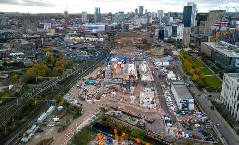
 Curzon Street Station site after first concrete pour of No 3 viaduct’s deck span – Nov 2023
Rail Engineer | Issue 207 | Mar-Apr 2024 27 STRUCTURES & INFRASTRUCTURE
Earthworks at Wendover Dean – June 2022
In HS2’s central section, it is estimated that there have been 35 million cubic metres of excavations of which made ground (any material affected by people) is approximately 1 million cubic metres. The most significant challenge is re-locating natural materials with distinct chemical fingerprints and leaching characteristics to geologically contrasting environments. This requires a detailed assessment of materials management at the scheme design and applying the four DoWCoP acceptance criteria as follows:
1. Protection of human health and environment – Advising site teams of constraints using graphical information systems with layers showing local wildlife, archaeological sites, and made ground. Regular meetings were held to inform the Environment Agency (EA) and CL:AIRE of site activities and project requirements.
2. Suitability of use – Zoning system agreed with the EA for re-use of made ground according to geology, aquifer classification, proximity to surface water and human health. Summarised Earthworks Quantity Schedules showing quantity and types of material in a section were compared with area material requirements.
3. Certainty of use – gaining HS2 Act schedule 17 consent for landscaping specification well in advance of the work to provide certainty of where material can actually be re-used.
4. Quantity required – Using EKFB’s DIGGER (Digital Graphical Earthworks Reporting) automated material tracking system to monitor excavated material movements from the place of origin to the final destination. This uses various data streams including GPS excavator trimble tracking and drone surveys to create a digital 3D earthworks model.
Reducing imported materials in this way reduces HS2’s carbon footprint. In 2022, the reuse of 25.6 million tonnes provided a reduction of 2.5 million HGV movements. Zara concluded her paper by emphasising the importance of effective engagement with the EA, local authorities, and CL:AIRE.
LEAVING A LEGACY
The London and Birmingham Railway’s (L&BR) proposal to build the world’s first long distance inter-city railway was the subject of much opposition and turbulent meetings in towns along the route. After a failed attempt, it eventually got its Act of Parliament approved in 1833. For its day, building the line was comparable to HS2. Twenty thousand men worked on it for five years and it required the movement of 12 million cubic metres of material.
When the line opened in 1838, there were six trains a day between the two cities and the train journey took five-and-a-half hours. This line’s legacy was demonstrating the feasibility and desirability of building railways between population centres, not least because of the economic activity they generate. This is still the case today as shown by the volume of freight and passenger traffic carried by the bottom part of the WCML which would have astounded the L&BR’s promoters.
Over almost 200 years, the London to Birmingham railway has been developed into one of Europe’s busiest rail corridors. In contrast, HS2 was designed as a high-capacity railway from the start. Although Government has chosen not to use this capacity, HS2 will offer Birmingham significant benefits which already include a large increase in inward investment. Hopefully, at some time in the future the decision to deny other cities the benefits of high-speed rail may be reversed as its benefits become more generally accepted.
Rail Engineer | Issue 207 | Mar-Apr 2024 28 STRUCTURES & INFRASTRUCTURE
Excavators and dump trucks fitted with automated material tracking as part of the DIGGER system
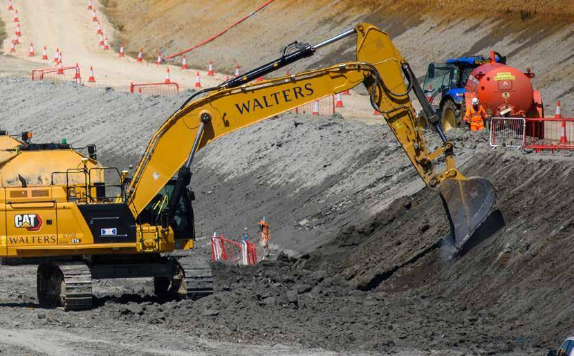
HS2’s other legacies will include adding to the UK’s iconic railway structures. The care taken to ensure its structures fit into the landscape includes specifying that bridge design teams must include an architect.
The project has also shown how major construction projects can reduce embodied carbon and use innovative designs that also offer environmental and safety benefits. Its Learning Legacy website has almost 200 papers which describe innovations and lessons learned with the aim of passing on new knowledge to improve UK productivity.
A significant legacy is building a diverse, skilled, and talented workforce across the project’s supply chain, of which 4% are apprentices. The intention is that this workforce will benefit the UK infrastructure industry for years to come.
Thus, despite being curtailed with reduced benefits, there is no doubt that HS2 will leave a lasting legacy.
HS2’S LEARNING LEGACY WEBSITE


Rail Engineer | Issue 207 | Mar-Apr 2024 29 STRUCTURES & INFRASTRUCTURE
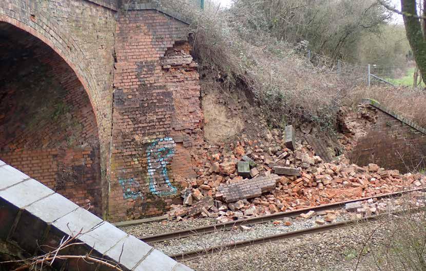


Structural failure at Yarnton
As is often the way with incidents and accidents, it is not one failure alone that is the cause but a series of isolated factors which can together conspire to lead to an unhappy outcome. This was certainly so in the case of a collapsed wing wall which was then struck by a train at Yarnton. The Rail Accident Investigation Branch (RAIB) has recently published its report into the circumstances and causes of the collision. It is not the intention of this article to paraphrase the RAIB report. Rather it is to inform structural examiners, examining engineers, asset managers, and maintenance contractors of the findings and lessons learnt from the incident, which potentially have system wide implications.
THE INCIDENT
The incident occurred in the early evening of 10 February 2023 at Yarnton, on the Oxford to Worcester line. Forward facing camera images from two recent trains showed the wall still standing, and a third train passed the site safely 19 minutes before the incident. At 18:35, the 17:34 Great Western Railway service from London Paddington to Hereford made an emergency brake application after striking fallen debris from the collapsed wall. Fortunately, there were no injuries to passengers or train staff and the train did not derail, but the incident resulted in damage to the train, preventing the completion of its journey.
The line remained closed while checks were carried out, but after reopening it had to be closed again after further ground movement of the slope above
the remains of the wall. It remained closed for several days until the completion of extensive work to stabilise the slope. The incident also necessitated closure of the roadway above for some time until it reopened with single lane working on 28 February.
HIDDEN DEFECTS
The wing wall in question formed part of a heavily skewed road over rail bridge. It is of an unremarkable type, in brickwork, similar to many other structures dating from the original construction of the railway. Unfortunately, though, for those now responsible for its inspection and maintenance, it had acquired hidden defects.
Owing to the skewed nature of this overbridge, the wing wall is formed in elevation as a long triangle, 13 metres in length and 5.3 metres in

RAIB Rail Engineer | Issue 207 | Mar-Apr 2024 30 STRUCTURES & INFRASTRUCTURE
MARK PHILLIPS
PHOTO:
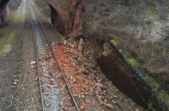
height, supporting a considerable extent of the road embankment. Throughout many years of examination, bulging of the wing wall and drummy areas of brickwork had been noted and monitored in some detail. Eventually this had led to a recommendation that repairs could no longer be postponed and this was budgeted for and was carried out in 2013. The specification was to ‘pin and grout’ throughout the areas of bulging with the aim of arresting any further outward movement of the wall and to ensure that structural support of the embankment was guaranteed.
Most unfortunately, because no record drawings existed from the original construction of the wall and neither of any subsequent work which might have been carried out to it, the internal circumstances and condition of the wall were unknown. That is, until after the collapse of the wall in February 2023, when the dangerous condition of the wall was revealed.
At some unknown date in the distant past a second skin of brickwork had been built in front of the original wall, presumably as an attempt to strengthen it in response to signs of distress. However, this second wall was found to have not been bonded into the original wall as would be expected. It was merely a facing, 100mm deep, a single brick thickness, and, as seen externally, apparently with header bricks to tie into the original wall. But these bricks were only halfbricks, known as ‘snap headers’ and they made no effective bond with the original wall. Adding insult to injury, there was also found to be a 100mm void between the two walls. Not only did the second outer wall fail to add any strength to the original
wall, but it also masked the hidden ongoing deterioration of the inner wall. Furthermore, regarding the actual collapse, it contributed a considerable additional volume of debris brought down onto the track, worsening the scale of the collision.
Because of the void between the two walls, the pinning and grouting work in 2013 would have been ineffective, with the majority of the grout falling into the void and achieving no bonding contribution. This became another ‘hidden defect’, in that asset engineers put more faith in this repair than it deserved and possibly led to their assigning higher scores in condition marking than was warranted.
STRUCTURAL EXAMINATIONS
The wing wall (as had all the other structural elements of the overbridge) had been subject to the standard routine regime of examinations, receiving detailed reports every three years and intermediate annual visual examinations.
In the 10-year interval between the 2013 minor pin and grout works and the collapse in 2023, the examination reports drew attention to ongoing deterioration with the bulging of the wall and the drummy areas of brickwork remaining of concern. However, it was not easy for examiners to make successful and accurate comparisons of deterioration between one detailed examination and the next. For example, a recommendation following the 2014 detailed examination report was made by the examining engineer to “Rake out fractures to sound material, point in and apply tabs to monitor for movement at future examinations.”
This recommendation applied to several areas of the bridge, but included the south-west wing wall, the wall which collapsed. It appears that the tabs were never actually installed. Also, while photographic records of the bulging and fractures were used at successive examinations, the angles from which the images were taken were not consistent and were of a low resolution, making deterioration difficult to judge. Network Rail now has a revised standard which specifies the requirement for high resolution images.
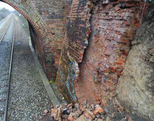 PHOTO: RAIB
Rail Engineer | Issue 207 | Mar-Apr 2024 31 STRUCTURES & INFRASTRUCTURE
PHOTO: RAIB

With a lack of any quantitative measurements of the amount of bulging and comments on successive detailed examination reports such as “…appears to be no visual change” and “...similar condition to the last exam. No new major defects and no worsening of existing defects,” the asset engineers would have had confidence that the 2013 repair had stabilised the wall. More detailed measurements would probably have led to recommendations to investigate the bulging and would have discovered the void between the original structural wall and the skin wall.
Ironically, the final visual examination in January 2023, three weeks before the collapse, did note from comparison of photographs while on site that the bulging appeared to have increased and that there was deterioration throughout the wing wall. However, these observations, were not deemed serious enough to immediately notify the asset engineer and this latest report was still under review by the examining engineer at the time of the collapse.
RISK ASSESSMENT
Network Rail has a company standard setting out the requirements for bridge condition marking so that each structure can be given a unique measurable score using the Bridge Condition Marking Index (BCMI). A score of 100 means that the structure is in perfect condition, whereas a score of 40 or less would normally trigger detailed examinations at a more frequent interval. Yarnton Road bridge had an overall BCMI score of 28 and the south-west wing wall had a score of 20.
There is also a risk assessment system to assist in the prioritisation of structural repair to an identified defect by assigning it a risk score. The score is the examining engineer’s judgment of the overall risk remaining should the defect not be rectified within one year. The score is derived from a 5 x 5 matrix to which severity factors are attributed for likelihood of a failure and the consequences should that occur, up to a maximum possible score of 25.
A risk score of 12 or more would normally lead to planning of remedial work. Following the 2014 and 2018 detailed examinations, risk scores of six and eight respectively were given. The slight increase in the later score was probably because the 2014 report noted that fractures to the wing walls had been pinned and grouted, but the 2018 report noted that no evidence of this could be found and also that the majority of the fractures were open.
The RAIB report suggests that the severity of consequence was underscored in both years and that this was possibly a result of scoring the structure as a whole rather than the wing wall specifically. Higher scores would possibly have led to remedial work being planned much earlier.
PLANNED REMEDIAL WORKS
Yarnton Road bridge’s low BCMI score and its poor condition did lead to it being proposed for major repair work in 2014 which was given a provisional start date of 2019/2020. In May 2019, that was changed to 2022/2023. This was again later changed to 2023/2024 due to resourcing limitations.
The scope of works proposed was to rectify defects identified in the most recent detailed and visual examination reports, particularly addressing the wing walls which were in poor condition throughout, with bulging, numerous fractures, spalled bricks, and drummy areas. There would be stitching across fractures and tying back bulging areas to sound material, all with the aim of achieving a theoretical BCMI score of 58.
Significant structural strengthening was not proposed at this stage, but that monitoring points would be put in after the repairs. If these showed ongoing movement was taking place, then work such as ground anchors or a reinforced concrete facing would be considered as the next intervention.
In January 2023, Network Rail rescoped the renewal programme because of insufficient budget. The Yarnton Road project was moved back to a provisional date of 2029. However, this was only a holding date pending completion of a deferred renewal risk assessment to justify the deferral. The risk assessment had not yet been done and the results might have indicated that an earlier date was needed. The RAIB report also comments that even had the work been done, the scope of that work is unlikely to have been adequate to have prevented the failure. This would only have been possible with the full knowledge of the internal condition of the wall and the specification of appropriate and more substantial remedial work, such as that outlined above.
POST-INCIDENT CHECKS
The other three wing walls at Yarnton Road were checked by drilling core holes. No other voids were found. However, another similar bridge not far away with bulges and fractures was found to have voids in all four wing walls. A temporary speed restriction was imposed until remedial works had been completed.
SUMMARY
In conclusion, the RAIB report identifies four Recommendations and four Learning Points and makes some other observations.
Full details can be found in report No.1/2024 here:

PHOTO: RAIB Rail Engineer | Issue 207 | Mar-Apr 2024 32 STRUCTURES & INFRASTRUCTURE


What is RailwayPeople.com?
RailwayPeople.com is the largest dedicated rail job board in the UK.

How can it help me?
With the top career opportunities updated daily, your next move is a fingertip away.

What should I do?
Visit www.RailwayPeople.com to find your new career and become an essential part of the UK’s rail industry to help the nation build back better.


Find your new career... ...today
PSSSST... NEW WEBSITE COMING SOON!
SEKISUI’S FFU:
Newark flat crossing four years on
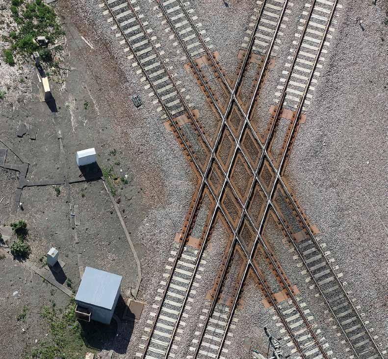
ALL PHOTOS PROVIDED BY SEKISUI Rail Engineer | Issue 207 | Mar-Apr 2024 34 STRUCTURES & INFRASTRUCTURE


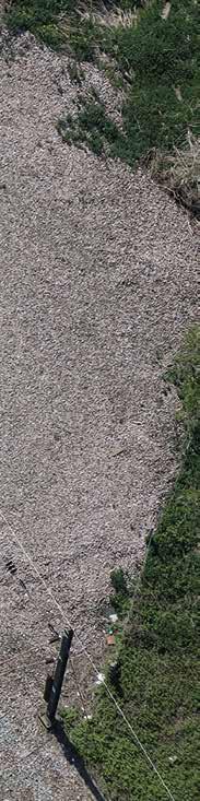
Sekisui manufactures synthetic wood baulks made from Fibre-reinforced Foamed Urethane (FFU). Network Rail engineers installed the first FFU baulks and sleepers as replacements for traditional hardwood on military canal bridges in Kent during 2014. The FFU product was first introduced on Japanese Railways in 1980 and early installations are still performing to specification. FFU is now widely used on railway infrastructure in 33 countries to support track on bridges, decking for level crossings, plain line sleepers, and switch and crossing (S&C) bearers.
Newark flat crossing is an example of a unique and large application of FFU technology on Network Rail infrastructure which required the development of the long FFU synthetic bearers forming a lattice track support 16 by 16 metres. Sekisui holds full Network Rail Product Acceptance Certification PA05/07176 for this project which became operational following complete track renewal in August 2019. The FFU was used to replace the traditional hardwood to support the track.
FABRICATED TO REQUIREMENT
The FFU baulks can be fabricated and milled to meet site specific geometry requirements including providing holes, notches, pockets, and variable cross level to individual design requirements. Key benefits over hardwood include longevity with over 50 years’ service life. FFU is form retentive, not prone to splitting or absorption of water, and does not rot or deteriorate in sunlight so it contributes significantly to ‘whole life cycle cost reduction’ by reducing track maintenance and renewal interventions. The product does not require maintenance inspectors to complete micro-drilling during service life and is fully recyclable.
Situated just north of Newark Northgate station, the flat crossing is located where the east-west Nottingham – Lincoln line crosses the East Coast Main Line (ECML). It is one of the most complex track structures on the route, with no fewer than 16 crossing noses, and carries 160km/h inter-city trains running north-south and heavy freight traffic on the east-west line.
Prior to the 2019 renewal, the supporting lattice that holds the cast crossings into position was made up from hardwood and typically required replacement every 15 years. The last renewal occurred in 2003. Network Rail found that procuring suitable hardwood timbers of 16 metres for a further renewal proved problematic. This led to the decision to adopt alternative technology which ultimately led to lower whole life costs by reducing track maintenance requirements and track renewal interval.
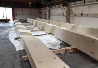
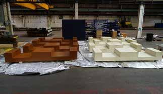
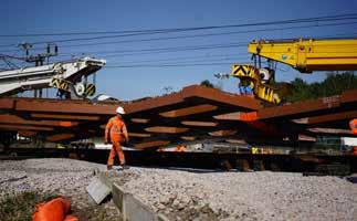
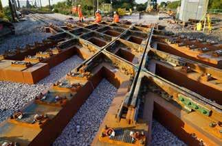

Thanks to close co-ordination between the various partners, the installation weekend went to plan.
After the end of services on 25 August 2019, the old trackwork was removed and the supporting ballast replaced, including the installation of geocells to strengthen the formation.
Whilst FFU has been used in various countries, this project is the first time that something on this scale has been fabricated outside Japan. The new bearers are expected to more than double the life of the lattice layout and reduce maintenance intervals, significantly contributing to a favourable business case. Network Rail engineers are considering how FFU could be utilised in other applications, including plain line sleepers, S&C bearers, and level crossings. Installation of FFU for waybeam bridges has full product approval.
NIGEL
KEIGHTLEY
16-metre-long special prepared FFU baulks
End cross baulks fixing two long bearers
Lifting the crossing into its final track position
Rail Engineer | Issue 207 | Mar-Apr 2024 35 STRUCTURES & INFRASTRUCTURE
Crossing placed on the prepared track bed
NEWARK FLAT CROSSING
For the Newark flat crossing renewal Sekisui offered to provide 16-metre one-piece beams, matching the existing wooden bearer layout. The FFU baulk material was manufactured in Japan to a maximum length of 8 metres. To produce the required 16-metre bearers, Sekisui partnered with Progress Rail to assemble the beams at a facility near Nottingham. This was the first time that this has been done outside Japan. From Spring 2024, FFU will also be manufactured in a new factory in the Netherlands.
The bearers were constructed from 30mm thick, 8-metreslong layers of FFU; these were manufactured in Japan and shipped to the UK for final assembly. Two densities of FFU - 740 and 1,000 kg/m3 (FFU 74 & FFU 100) - were combined in laminated form to give an increased compressive strength near the surface.
Specialists from Sekisui worked with staff from Progress Rail to assemble the bearers. These were combined with the other railway elements including the rails and Cast Manganese Crossings manufactured by Progress Rail to complete the huge crossing lattice assembly, weighing more than 40 tonnes. The design was complex, with the interlocking components designed to ensure that the construction matched the specification.
After eight weeks, the novel FFU bearers were finished, numbered, painted, and assembled into the lattice form in the factory to confirm fit. The crossings were then attached by Progress Rail, drilling into the new material which behaves like hardwood. The trackwork was renewed using CEN56 HP rails instead of the previous 56 kg/m BS113A rails, along with new cast steel crossing inserts. Once everything had been fitted accurately each component was marked and the crossing partially dismantled for transport to site. The various components were taken to Newark by rail at the end of July 2019 and reassembled on a site adjacent to the line ready for installation.
MAINTENANCE COMPARISON AFTER FOUR YEARS
Over four years after the renewal of Newark Flat Crossing utilising FFU, Network Rail Track Maintenance Engineers (TME) in Doncaster report significant reduction in maintenance requirements.
The TMEs gave feedback comparing the same time-period after the 2003 renewal:
2003-2007 hardwood timber renewal - track geometry deterioration, ride quality issues, splitting of timbers, failure of screws, several rail management interventions to cast crossings, including cracking of castings leading to early replacement of ironwork.
2019-2023 FFU renewal – stable track geometry with no ride quality issues reported, no screw failures, no deterioration in the FFU material, reduced rail management intervention and no cracking or premature replacement of cast crossings.
In terms of rail management, since the introduction of FFU, Network Rail’s TMEs have reduced the cyclical inspection and maintenance requirements from four-weekly to eight-weekly. There is now only minimal crossing nose profile grinding required and two small casting weld repairs have been done to date.
Sebastian Smith, route engineer (track) East Coast Route, York, commented that his team viewed the project as “a success, with the FFU seeming to offer a fit and forget characteristic which is very beneficial to a maintainer”. He is delighted with the project, stating: “the decision to install based on whole life cost is proving to be correct”.
Sebastian is looking forward to introducing FFU into Switch and Crossing layouts in the next Control Period, as well as a continued Waybeam Bridge renewal programme on the East Coast Route.
Many thanks to Simon Hunt, track maintenance engineer, Doncaster and Sebastian Smith, route engineer (track) East Coast Route, York for their input to this article.
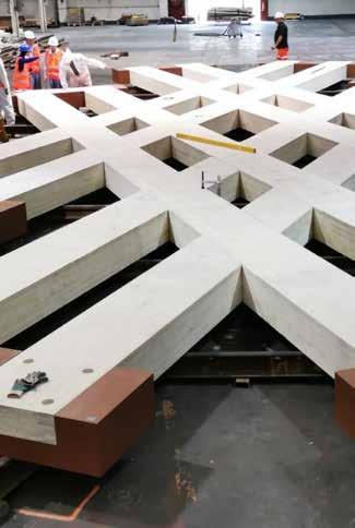
FFU: A BACKGROUND
Developed in conjunction with Japanese National Railways, FFU synthetic sleepers are made using the pultrusion process. Continuous glass fibres are soaked and mixed with polyurethane, and then hardened at a raised temperature, moulded, pulled, and cut to length. This creates a high-quality material that has the life expectancy of plastic and the weight of natural wood. It can also be worked like natural wood.
First installed in Japan in 1980, and adopted for standard sleepers since 1985, FFU has subsequently been installed on several projects in Europe over the past 20 years, particularly turnouts and bridges. FFU sleepers are currently used on more than 1,950km of track around the world.
Tests of the original 1980 FFU sleepers, undertaken by the Railway Technical Research Institute in 2011, predicted that the sleepers could safely continue in use for another 20 years, giving a total life of around 50 years. FFU sleepers have also been certified by Germany’s Federal Railway Office for use on tracks operating at up to 230km/h and 22.5 tonnes axle load.
Rail Engineer | Issue 207 | Mar-Apr 2024 36 STRUCTURES & INFRASTRUCTURE
Pre-assembling and approval of lattice before the installation of cast crossings
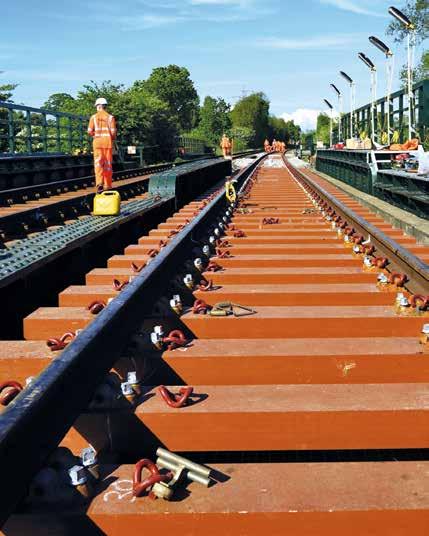

Synthetic Sleeper
Simply working & sustainable
Since 1985 we have installed more than 1,850 km of track 1.7 billion load tonnes | equivalent of 50 years use
Application: Ballast, Slab Track, Steel Construction and Direct Fastening
Can carry Axle loads of up to 65 tons
Use on High Speed Rail up to 300 km/h
Maintains long term track geometry
Contact with ballast similar to timber sleepers
Workable properties like timber sleepers
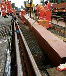


RAILWAY TECHNOLOGY SEKISUI CHEMICAL GmbH Patrick Childs | T: +44-(0)796-6598055 E-Mail: childs@sekisui.de www.sekisui-rail.com
State of the Art


shaking up
UK rail electrification
The commitment made in the UK Government’s Decarbonising Transport Plan for an ambitious programme of railway electrification is both complex and challenging. With progress sat at just over a third of the 13,000km of track in Great Britain’s rail network electrified, the rollout required is extensive. To achieve its targets, Network Rail has called on suppliers for support –challenging the status quo and developing innovative solutions to promote efficient, effective, and safe electrification projects.
One such innovation is the SwiftLine Rail Dropper from Gripple. Recently approved by Network Rail and the Federal Office of Transport (FOT) in Switzerland, this new dropper changes the game for overhead line equipment (OLE) maintenance and repair, helping contractors maximise possession windows and complete faster and safer dropper installations.
ALL PHOTOS PROVIDED BY GRIPPLE
SwiftLine Rail Dropper
Rail Engineer | Issue 207 | Mar-Apr 2024 38 FEATURE
DEVELOPMENT
Maintenance, repair, and improvement work to OLE is one of the most challenging aspects of any electrification project. Having the right solutions on hand is essential to ensuring work can be completed safely and efficiently. Hanging vertically to connect the catenary and contact wires at regular intervals, OLE droppers are an essential component of electrified railways, providing support and conductivity to both wires and ensuring long-lasting stability across the network. The challenge with rail droppers arises with installation. According to research undertaken by the University of Sheffield as part of the UK Rail Research and Innovation Network (UKRRIN), installing rail droppers is one of the most timeconsuming aspects of an OLE project. It is one of the reasons highlighted for the slow rollout of electrification. With OLE possession windows already placing extreme time pressure on engineers, the need for a faster, easier-to-install rail dropper is paramount.
Familiar to the rail industry, with its ground-anchoring systems used for embankment stabilisation, Gripple saw this as an opportunity. Applying the same technology it already applies to catenary suspension in other markets, Gripple identified similarities between the problems OLE installers were facing and those it was already solving in the building services sector. Taking a collaborative approach to innovation, Gripple engineers took on board the feedback from contractors and other industry stakeholders, understanding the challenges they face and solving them. The result is a game-changing solution – faster, safer, and easier to install than any other dropper on the market and set to make a massive difference to electrification projects up and down the country.
ADDRESSING CHALLENGES
Gripple prides itself on being a problem-solver. On designing products that tackle the real on-site challenges facing contractors every day. Its SwiftLine Rail Dropper is no different. As with many major infrastructure projects, the biggest challenge facing OLE engineers is time. Possession windows are never long enough, and with large fines facing firms that exceed the allocated time for maintenance and repair, it’s in everyone’s interest to install efficiently.
Conventionally, OLE droppers are supplied as a kit and need to be cut to length and assembled on-site. This is extremely time consuming with great care and attention required to ensure the correct and accurate installation.
Designed to be quicker, safer, and easier to install, Gripple’s SwiftLine Rail Dropper comes pre-cut and pre-assembled, giving contractors a ‘plug and play’ solution straight out of the box. This completely removes the need to cut, crimp, and fix on-site, saving installers hours on assembly times and significantly reducing the likelihood of human error.
Available in a choice of pre-cut lengths, the Gripple SwiftLine Rail Dropper offers infinite height adjustability meaning one dropper can meet a variety of drop lengths. This saves time on specification and installation and vastly reduces the risk of waste if the drop length is measured incorrectly. The pre-assembled design also allows for tool-free installation with minimal training, making projects simpler and safer, limiting the time engineers spend working at height and in the dark.
Similar challenges occur with the contact clamp torque. Installed and set manually using hand tools, often in the dark, at height, and under significant time pressure, setting the correct torque is susceptible to user error. Exposing projects to high replacement costs or delays to ensure accurate installation. To address this, the SwiftLine Rail Dropper features an innovative Auto-Torque contact clamp, using a pre-set lever clamp to provide a set clamping force, guaranteeing ‘right-first-time’ installation and the correct torque every time.
Improving the speed of installation while ensuring a fully conductive product, the SwiftLine Rail Dropper utilises Gripple’s unique Volt Lock System. Housed within the catenary wire top dropper and including a roller which both grips the dropper wire and ensures constant contact with the copper housing of the product, this unique feature makes the product fully conductive at all times and allows for greater adjustability and speed of installation when fixing to the contact wire.
QUALITY AND TESTING
While the demand for innovation in the rail sector has never been greater, it must be approached with care. Products used in UK rail infrastructure must first be subject to Network Rail approval, providing assurances that products are fit for purpose, safe and reliable, and do not pose risks to the railways.
Rail Engineer | Issue 207 | Mar-Apr 2024 39 FEATURE


The Gripple SwiftLine Rail Dropper went through an unprecedented level of testing to ensure it would exceed the requirements of Network Rail and the BS EN 50119 standards, evidencing its unrivalled durability and reliability.
In the pursuit of further input from industry stakeholders, Gripple has continued to engage key players to test the SwiftLine Rail Dropper. This includes recent installations on the Sandwell and Dudley Line between Wolverhampton and Birmingham. The feedback has been outstanding, with engineers citing the ease and speed of installation and the height adjustability as critical benefits when working within tight possession windows. Manufactured in the UK with complete transparency in environmental testing and product traceability, Gripple SwiftLine Rail Dropper offers OLE engineers and contractors the highest quality and most sustainable OLE dropper on the market. Boasting its own sustainability credentials, which includes carbonneutral UK operations and vertical integration, Gripple is supporting the
net-zero agenda, helping to provide transparency and continuity to its customers.
To help launch the product to market in the UK, Gripple has partnered with established rail supply chain experts Unipart Rail with the aim of making the SwiftLine Rail Dropper as accessible as possible to the market.
CONCLUSION
With no less than nine unique product features and the result of two years of robust testing and development, the Gripple SwiftLine Rail Dropper is an OLE dropper more advanced than anything else on the market. With installation times up to eight times faster than a traditional dropper, this product allows OLE engineers to take control of electrification projects, get more done in each possession window, and bring forward project completion dates. As the journey towards electrification continues, the Gripple SwiftLine Rail Dropper should be at the forefront of the transition and in the arsenal of OLE engineers up and down the UK rail network.
Rail Engineer | Issue 207 | Mar-Apr 2024 40 FEATURE
This isn’t just a rail dropper.
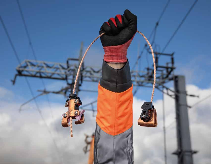
The Gripple SwiftLine Rail Dropper has the power to deliver your maintenance projects faster using fewer possession windows. Save budget and time using this innovative Network Rail approved solution delivering OLE repairs at pace. It’s fewer possession windows.
You’ve got to see it to believe it gripple.com/swiftline/

Available from Unipart Rail (Official UK Distributors) E: enquiries@unipartrail.com T: +44 (0)1270 847600 Gripple E: sales@gripple.com T: +44 (0) 114 275 2255


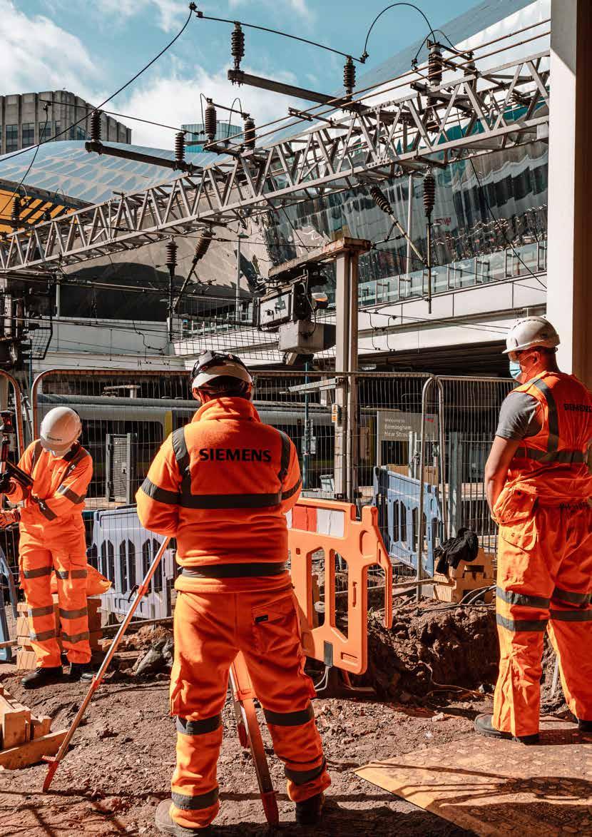
Rail Engineer has reported on the extensive West Midlands resignalling a number of times over the years, issue 160 (February 2019) covered the completion of phase 6 between Birmingham New Street (BNS) and Birmingham International stations. So, we were delighted to meet up with main contractor Siemens to learn how things had gone with the final phase 7 and the resignalling of the complex and tight BNS area, which resulted in the final closure of Birmingham New Street Power Signal Box (PSB) on Christmas Eve 2022 with control transferred to the West Midlands Signalling Centre (WMSC) at Saltley. The final phase presented a number of challenges for all involved.
Birmingham New Street station is the UK’s busiest interchange station outside London, handling over 140,000 passengers and around 1,200 trains daily – that is a train movement
around every minute. The interlocking, installed in the PSB in the 1960s, was one of the last remaining Westpac Mk1 geographical relay interlockings in the country. Problems such
BIRMINGHAM NEW STREET PHASE 7
ALL PHOTOS: SIEMENS MOBILITY OP EN HE ART SURGERY IN THE MIDLANDS Rail Engineer | Issue 207 | Mar-Apr 2024 42 SIGNALLING & TELECOMMUNICATIONS
PAUL DARLINGTON
as silver migration were a safety concern, and other assets such as lineside cables and interface relays were becoming fragile. The system wasn’t flexible enough to make the most of the limited infrastructure at the station and, with the increased footfall of passengers expected to increase over the coming years, signalling upgrades were needed.
The platforms at BNS are mainly covered with a large shopping centre above the station. The station’s structure, and its deeply urban nature, significantly reduce accessibility and space to located equipment. The layout of the station is also restrictive, with one bay, 12 through platforms, and four lines at each end of the station. The complex and tight layout results in signals often protecting fouling points that are very close to the signals. Passing a signal at danger, even by a small amount, is likely to infringe a fouling point and cause disruption. It’s also necessary for two trains to frequently occupy one platform, and to split a train or join two trains together.
To squeeze the track and platforms into the limited space, signalling design compromises have always been required. For example, Automatic Warning System (AWS) has never have been provided at BNS. Resignalling to modern standards has increased the challenges to identify and obtain the necessary derogations, and to achieve the operational requirements.
PLANNING AND DELIVERY
Work on BNS phase 7 started in 2017 with a twoyear single option development stage, followed by a three-year detailed design, construction, and testing stage. The early planning and definition of the staging approach was crucial to minimise disruption to passengers and freight customers, and required close cooperation between all stakeholders including the many Train Operating Companies (TOCs) and Freight Operating Companies (FOCs) involved.
Under the original programme a six-day commissioning blockade of BNS would have been required, along with four 29-hour blockades. A complete shut down for such a lengthy period would have caused unsustainable disruption. So, the concept of staged interventions was devised. This used Rules of Route access and a full blockade on 25-26 December 2022, together with early closure on 24 December and a later start to services on 27 December. Services through and around the station ceased for 72 hours while 352 staff implemented the final elements of the scheme.
This approach involved 83 compressed stages carried out over two years, with rehearsals of the major stages in order to reduce risk of disruption in the final commissioning stage. Non-disruptive access was used throughout, which further complicated the planning work required.
This stage working approach required 12 platform closures, with the affected platforms segregated from the adjacent platform to minimise disruption
and to maximise workforce safety. Through constant reviews the team managed a wide range of planned and unexpected events. During 2022, more than five million people visited the city during the Commonwealth Games, doubling the city centre’s footfall. The 70th anniversary of Queen Elizabeth’s accession to the throne and the resulting jubilee celebrations saw another surge of rail demand, as did travel around the time of the Queen’s funeral later that year.
The greatest challenge to the project however was Covid-19, which radically changed the way work could be delivered. Strict health and safety protocols had to be adopted to protect the workforce and minimise the risk of infection. Train ridership plummeted, but the importance of services to and through the station for key workers and critical freight services remained, and work had to continue with minimised disruption.
Over the four years of detailed design, the project integrated over 300 improvements of varying sizes that hadn’t been detailed within the original scope. This included on-track additional walkways to allow drivers to leave cabs safely.
SIGNALLING TECHNOLOGY
The Westpac Mk1 signalling was replaced by a processor-based Trackguard Westlock interlocking located in the WMSC along with the new control system. The Westlock manages Westrace Trackside System (WTS) equipment throughout the area, located in trackside location cases or relocatable equipment buildings, and connected over the Fixed Telecommunication Network (FTN).
Manufactured in the UK, this was the first deployment of this digital railway technology in the West Midlands, and introduced benefits such as faster route setting, the ability to operate with longer tail cables and improved immunity to traction interference, with the extensive use of fibre-optic instead of copper cables. Being processor based, the system is more flexible should modifications or changes be required and is capable of being used with ETCS.
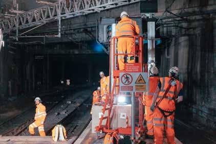
Rail Engineer | Issue 207 | Mar-Apr 2024 43 SIGNALLING & TELECOMMUNICATIONS
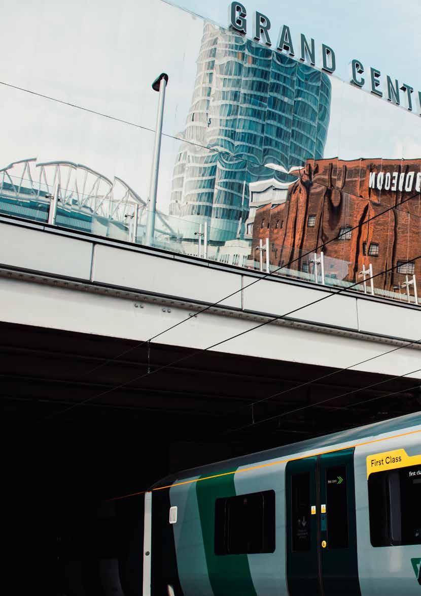
Several novel signal indicators and axle counter developments were required to reduce clearances, compared to normal signalling. Thales axle counters were used for train detection and the signals replaced with LED units. The sheer scale of the project is such that 114 signals, 228 axle counter sections, 30 location cases, and eight relocatable equipment buildings were installed along with 11,000 metres of cable troughing protects, 78,000 metres of power and fibre cabling, and 245,000 metres of tail cables. For the power system, 35 Functional Supply Points (FSPs), four Principal Supply Points (PSPs), two Distribution Network Operator Cubicles (DNOs), and two 25kV ‘take offs’ from the Overhead Line Equipment (OLE) were also installed.
Plug coupling was widely used for the points (requiring retrofitting of plug coupled connections for many assets) and new signals in order to allow rapid changeover during rehearsals and the main commissioning.
Special bespoke brackets were designed to hold the mid-platform signals. The brackets wrap neatly around the bulkhead cladding fixing on the structural concrete beams to provide sufficient headroom on the platforms. This required careful design to work around station lighting systems to ensure compliant illumination.
Cable management provided another challenge, with hundreds of cables from the equipment rooms fanning out to equipment located around the station. This required excavations on each platform, often by hand, to allow cross-platform cable routes to be installed. Most of this work was carried out during short overnight possessions with the platforms reinstated, cleaned, and reopened for passenger use each morning.
INNOVATIONS
A number of new approaches were taken, some for efficiency, and some to meet the specific needs of the project. Twenty-six Train Despatch Equipment Units (TDEUs) were installed to show train despatchers information about the current status of the signalling in order to improve the number of on time departures. These innovative units were developed to provide improved efficiency, reducing risk of human error, and safer train dispatch.
Two 900 square foot, climate controlled, equipment rooms were built on site at the ‘A’ end of the station to optimise the use of restricted space, to comply with the sub surface fire regulations, and to allow construction while the station remained open for passengers. Each room houses the equivalent signalling control equipment of four traditional REBs along with separate rooms for telecoms and Electrical & Plant (E&P) equipment. Combined with the longer tail cables that can be used with WTS, this allows a centralisation of the trackside control equipment, reducing the quantity of trackside location cases and reducing the risk of staff accessing and working in trackside locations in the confined environment.
At the ‘B’ end of the station, space was freed up by moving redundant equipment. This allowed the use of more traditional signalling REBs, although some ‘double stacking’ was necessary to fit everything into the space available.
In order to help drivers and signallers fully understand the new signalling, extensive use was made of simulator-based training. Twenty-six signallers used an interactive 3D representation of the routes into the station to familiarise themselves with the changes. A 3D model of a train cab was created to allow drivers to virtually learn the route. This not only provided a safe system to train but also allowed useful feedback to further improve operational effectiveness.
Relocatable temporary signals at platform ends were used in order to facilitate the platform closures required. These allowed the new signals to be installed during each stage and enabled rapid changes to the signalling layout. The bases and posts were designed to be modular and adjustable, allowing them to be relocated around the station for the following stages.
Traditionally, in Great Britain, signalling tail cables are limited to 200 metres in areas of OLE to reduce the risk of induced voltages causing failures or false operation. This traditionally meant that a suite of signalling location cases is required near to most signals. Longer tail cables allow fewer lineside location cases/REBs for a more efficient design, particularly where space is constrained. The cost savings to provide safe accessible location suites were significant.
The pioneering use of long tail cables in Network Rail, required extensive modelling, site testing of induced voltages, detailed analysis, and on-site equipment trials to demonstrate safe and reliable operation. This saved the need for five location suites and the methodology developed is now being replicated on projects across the country.
Thales axle counters were used, these being the local standard for train detection. However, a number of developments were introduced for the complex and compressed BNS track layout, with some clearances reduced by half following analysis and site testing. Reliability was enhanced through the use of two-out-of-three, rather than the traditional two-out-of-two processor architecture.
Communication between the axle counter processors was via fibre optic links. A direct communication link was also used between the axle counters and the Trackguard Westlock interlocking, the first time this had been done in Network Rail, and this removed the need for a relay interface. Duplicate axle counter heads with diverse cable routes were also used to allow automatic changeover between heads should one fail or suffer a cable strike.
Given the restrictive nature of the site, localised modelling was used to position key signals and indicators to exceptionally fine margins to achieve the requirements of the signal sighting process and assess potential ‘read-across’ issues.
Rail Engineer | Issue 207 | Mar-Apr 2024 44 SIGNALLING & TELECOMMUNICATIONS
CONTROL SYSTEM TECHNOLOGY
As part of phase 7, the BNS area was recontrolled using a processor-based Controlguide Westcad workstation located at the WMSC. Train operator staff are now co-located with Network Rail signalling staff so that they can work together to problem solve more cohesively and reactively. This reduces the impact of late running services or platform changes by use of the modern control system to increase route reliability and platform flexibility.
A number of modifications were made to vastly improve railway operations. Although the system delivered in the 1960s allowed for some bidirectional movement in the station area, this was not possible on the approaches. The phase 7 work created a bi-directional loop for Platforms 1 to 7 (via Monument Lane) and Platforms 7 to 12 (via Five Ways and the Gloucester line) in addition to connection to a number of new sidings. This improves flexibility and allows line speeds to be increased to reduce journey times.
Extensive telecoms work was also required. This involved designing and installing three new nodes on the FTNx IP telecoms network and 10 existing nodes were upgraded. A two-stage approach was taken to create the telecoms network to allow signalling rehearsal testing 12 months before the final commissioning, with a controlled changeover to the final configuration. At the WMSC the existing analogue telecoms concentrator was replaced with a digital system to improve call handling.
SUSTAINABILITY
All partners in the project committed to sustainable delivery, as they were very aware of the large number of railway neighbours that were likely to be affected by the work. One example was the creation of a new, award-winning site welfare/depot facility, around 2km from BNS on an undeveloped site. Having been cleared and improved, the new depot was fully solar powered, saving around 75,000kg of CO2 emissions over three years.
Electric tools and equipment were used to reduce emissions and to improve safety by reducing the flammable liquids on site. Battery-operated power tools, mobile elevating work platforms, solar powered
welfare units, and solar powered tower lighting all contributed to the sustainability objective.
Delivery of the PSPs and REBs at Monument Lane required a 1,000-tonne crane lift over the main lines to Wolverhampton from an adjacent park. A temporary access road and pad were constructed, which involved cordoning off a section of a primary school playing field. Siemens Mobility worked closely with the both the school and council, and supported the school with construction of a new sensory space and the city with a donation to the charity Trees for Life, to support the planting of more trees.
OCCUPATIONAL SAFETY
Getting everyone home safe every day is a Network Rail commitment, so as part of the safety strategy, and with most of the work under cover and in the confined station area, a plan had to be implemented for preventing dust inhalation. Tools with dust extractors were used to protect the teams. Throughout the Covid-19 emergency, even greater protection measures had to be implemented, so airfed face masks were used to overcome the hazards from the dusty environment, which then formed part of the project’s Covid-19 protection measures.
CONCLUSION
There was no chance of a lengthy closure due to the geographical location of BNS and the critical nature of the infrastructure to the economy. By adopting a collaborative approach, using detailed knowledge of the existing infrastructure and an innovative application of digital technologies, the team successfully delivered a major upgrade with minimal disruption, despite a wide range of challenges.
Passengers and freight operators are already seeing an improvement in their journeys through this central hub, with fewer unplanned stops outside the station and more on-time arrivals.
With thanks to Steve Bick, project director, and Andrew Cardiff, senior project manager at Siemens Mobility Limited for their help with this article.
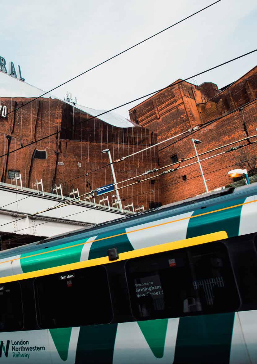

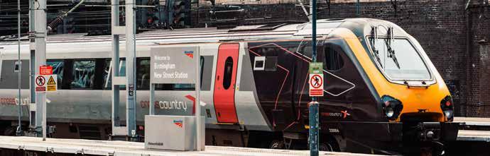
Virtual reality keeps Birmingham’s iconic power signal box alive - produced by eXtended Realities at the University of Birmingham Rail Engineer | Issue 207 | Mar-Apr 2024 45 SIGNALLING & TELECOMMUNICATIONS
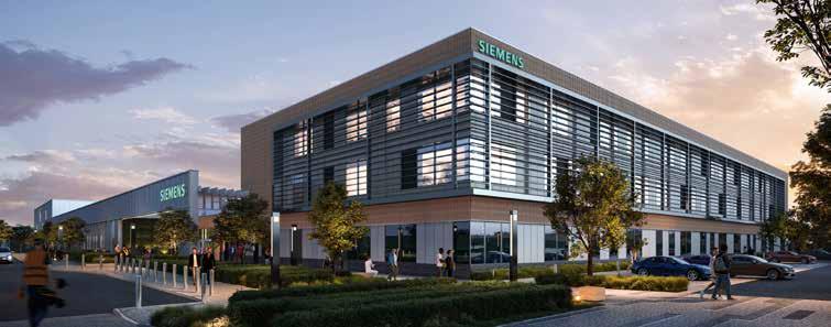
Siemens Mobility
BOOST for Chippenham
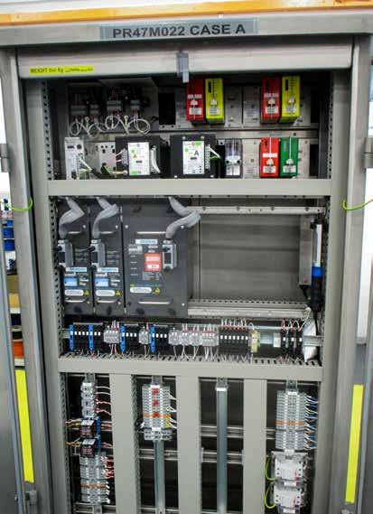


The recent announcement by Siemens Mobility to invest £100 million in the building of new premises in Chippenham was well received and duly reported by press releases on 4 March. Some of us were lucky to be invited to the associated press conference where the guest of honour was Chancellor of the Exchequer Jeremy Hunt. The press briefing gave details of what will be entailed but behind the scenes, the rail magazines were given the opportunity to probe deeper into the decision making behind the investment and the plans for Siemens Mobility’s future in the rail signalling business.
A BRIEF HISTORY
Those of us who have been in the railway signalling business for decades will associate Chippenham with the Westinghouse Brake and Signal Company. The origins go back much further than that. It was in 1856 that Saxby began to design and build signalling systems and equipment, and, in 1897, Saxby & Farmer opened a factory in Chippenham to meet the growing demand for signalling both in the UK and across the empire. In 1935, Westinghouse took control and continued to expand the site until the mid-Twentieth century. Eventually, Westinghouse was acquired by Hawker Siddeley in 1979 which was then then bought by BTR in 1992. Shortly after this, BTR merged with Siebe and became Invensys, continuing the signalling operation until finally Siemens acquired the business in 2013 to merge it with its signalling interests in Germany and other locations in Europe.
CLIVE KESSELL
PHOTO: SIEMENS MOBILITY
Rail Engineer | Issue 207 | Mar-Apr 2024 46 SIGNALLING & TELECOMMUNICATIONS
PHOTO: CLIVE KESSELL
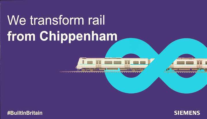
Some notable developments emanated from the site down the years, notably the London Underground Victoria Line automatic train control system in 1968 and participation in the development of solid state interlocking of which the first example was introduced at Leamington Spa in 1985. The Victoria Line system was replaced with a ‘distance to go’ radio based ATO system in 2012, which has performed very well since then. This pedigree of expertise was recognised by the German company, which made the site the leader of signalling development for both the UK and the wider market.
Siemens has been in Britain since 1900 where it was instrumental in introducing the first submarine cable link between England and India, then on to laying cables across the Atlantic. The company regards Britain as its second home and has many premises in the UK other than railway signalling. Another important part of Siemens is the factory at Poole where it designed the train mobile radio for GSM-R, although manufacture of the radios has now transferred to Chippenham. Radio communication is an essential element of the ERTMS progression.
Siemens is well established in the rolling stock business and its recently-opened factory in Goole will be manufacturing the new trains for London Underground’s
Piccadilly Line. Many other trains in the UK have been provided by Siemens including the Thameslink Class 700, the GN Inner Suburban Class 717, and the main line fleet for South Western Railway, and 587 of the trains supplied are maintained by Siemens depots around the country. Altogether, Siemens employs 5,500 people in the UK.
EXISTING CHIPPENHAM SITE
The expansion of the signalling business over the years led to a piecemeal development of the premises just on the north side of Chippenham railway station. It had its own rail sidings for many years and had several buildings geared to designing and manufacturing the signalling equipment of the time. It also had its own foundry to cast metal for the many structures and mechanical components as part of the signalling portfolio. The foundry no longer exists and is now only a pile of rubble.
Whilst the headquarters block remains, together with some factory units suitably adapted for the emerging signalling technology, some of the old buildings are in a derelict or semi derelict condition. This does not present the image of a modern-day signalling company, hence the need for new premises. Some of the land nearest to the railway has already
been developed into a retail park and the entire site (which Siemens does not own) will be used to develop housing and other local amenity facilities.
THE NEW SITE
The new factory and laboratories will be on greenfield land on the south side of Chippenham in the SouthPoint business park. Planning consent is at an advanced stage and the new premises are expected to open in 2026. The new building will incorporate all the latest sustainability standards promoting environmental and socially responsible structures.
As well as accommodating the officebased staff, there will be manufacturing, design, project engineering and research & development (R&D) facilities. Of the 800 staff who will transfer to the new site, 160 of these will be associated with R&D (there are a total of 300 staff working on R&D for signalling across the various Siemens UK companies). The aim is to have a seamless move so as not to disrupt design and production for the various signalling projects that the company has orders for. The skill sets that have been built up over the years are considerable, hence the decision to remain in Chippenham. It is intended that the research and manufacturing units will be the most modern of their kind in the whole world.
PHOTO: SIEMENS MOBILITY
Rail Engineer | Issue 207 | Mar-Apr 2024 47 SIGNALLING & TELECOMMUNICATIONS
PRESENTING THE OPPORTUNITIES
In the announcements made at the press briefing and subsequent interview sessions, Jeremy Hunt remarked that the government will back this plan as it is seen as a revival of manufacturing in the UK. The country must become a global leader of industry based upon technology. Manufacturing is 10% of the UK economy and this must grow. Artificial Intelligence, Life Sciences (medicines and vaccines), Film and TV, Automotive, Aerospace, and Railways, are all part of this growth plan. Emphasis must also be put on export. The old model of R&D in the UK but with manufacturing elsewhere in the world, is no longer acceptable. There is a need to shake off the negativity that so often prevails and restore our self-belief, he said. Tax reliefs of up to 25% will be there to encourage this objective.
Rob Morris, the joint CEO of Siemens Mobility, observed that much of the UK’s signalling infrastructure is approaching the end of its economic life. Some notable recent projects have included the CBTC on the centre section of the Elizabeth Line, the re-signalling at Birmingham New Street, the Core Valleys upgrade in South Wales and the ongoing East Coast Digital Programme (ECDP).
In the immediate future, contracts are in place for the work in mid-Cornwall to replace old mechanical signalboxes and the reopening of the Northumberland Line to Ashington. However, much more needs to be done and a long-term strategy has to evolve if the boom-and-bust type of business is to be avoided. The announcement of a five-year renewal programme for signalling will help this.
The ongoing Siemens Mobility product line will include both the deployment of ETCS and the continuance of modular signalling systems that have helped to reduce costs for secondary routes. The roll out of ETCS in the UK remains painfully slow, and even the much-publicised ECDP only covers from London to just short of Grantham, which is about a quarter of the entire route.
The company is well aware that the radio bearer for ETCS, which is currently GSM-R and obsolete in terms of its technology, has to be renewed in the next 5-10 years. The successor will be FRMCS based on 5G technology and Siemens intends to participate in that renewal once the business intent is made known. Another innovation is the possibility of cloud based interlockings where interlockings from different manufacturers can be remotely accessed to improve flexibility and reduction in cost. The existing Siemens interlocking types Westrace and Westlock will remain in production for both UK projects and others in the wider world.
Chippenham will work alongside the sister Siemens Mobility company in Braunschweig which has around 4,000 employees engaged on projects in Europe and around the world. €60 million has been invested here over the past five years. The Chippenham site already manufactures relays for Germany.
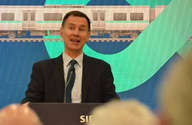

A nice touch to enhance the proceedings was to have Yasmin Rawle, a Strategy and Business Development graduate, tell of her involvement inside the company which goes back to four generations of her family. Employing graduates and apprentices will continue in increasing numbers once the new site is opened.
A final comment from Andrew Haines, the chief executive of Network Rail, emphasised the importance of rail growth in the UK where £43 billion is allocated to rail investment over the next four-year period of which re-signalling will be a significant element of this. Small and medium enterprises are predicted to be 50% of the suppliers to Siemens in the ongoing signalling modernisation.
THE FUTURE BECKONS
The news of Siemens Mobility’s investment has been well received by the local community, the signalling industry and, perhaps more importantly, existing employees. It ensures that a major contributor to signalling design and manufacture will remain in the UK, both to serve the home market of main line and metro operation as well as opening up new opportunities for export.
Whilst a few may shed a tear when the old site finally closes, it is no longer fit for purpose and it is time to move on. Rail Engineer will continue to keep in touch and report on progress with the new facilities as the building work gets underway.
Jeremy Hunt
Rail Engineer | Issue 207 | Mar-Apr 2024 48 SIGNALLING & TELECOMMUNICATIONS
Rob Morris

Cyber security in rail
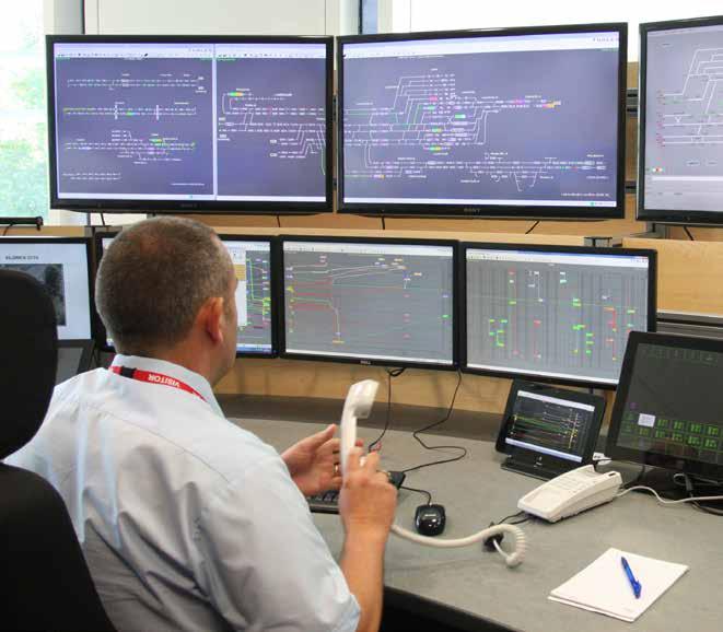
Rail Engineer has previously published articles on cyber security, and it is a subject that will be undoubtedly covered many times in the future. Protecting data and keeping systems safe is still not universally recognised as something we should all be doing, and instances of hacking with damaging and often costly results happen all too frequently. It is necessary to issue and re-issue ever present reminders about the threats and how they can be spotted and managed to avoid business disruption or unsafe situations.
Railways in general are well aware of the risks involved, and most administrations do understand the broader measures needed to keep the trains running safely and the operational processes intact. However cyber attacks do occur, often because the circumstances are not perceived as possible, and the resulting loss of service can be very embarrassing.
A recent IET webinar given by Stefano Saccomani and Richard Thomas from AtkinsRéalis told of the ever-changing face of cyber threats within the rail landscape.
KNOWN INCIDENTS
Three incidents were described and analysed:
» In October 2022, the train Danish operator DSB suddenly found that numerous trains were being cancelled. A crucial test environment provided by Supeo took down vital interfaces. The investigation found that a single failure of one system took down many other systems.
A third-party supplier was the single source of failure and the risks had not been properly assessed.
» In August 2023, the sending of emergency stop messages in Poland brought 20 trains to a halt. The impact of these stops affected many other services, and the problem took six hours to resolve. The cause was the VHF train radio system, an open channel with no encryption, which had been accessed by outsiders. The radio documentation could be accessed easily, with very poor assumptions made that the system would not be of external interest.
» In December 2023, again in Poland, a supply chain software malfunction caused a denial of service that affected train services. The train manufacturer was aware of cyber threats, but the software did not perform as well as intended. There was a general lack of awareness of the software’s state, made worse by additional interfaces that provided entry points to the system.
PHOTO: NETWORK RAIL
CLIVE KESSELL
Rail Engineer | Issue 207 | Mar-Apr 2024 50 SIGNALLING & TELECOMMUNICATIONS
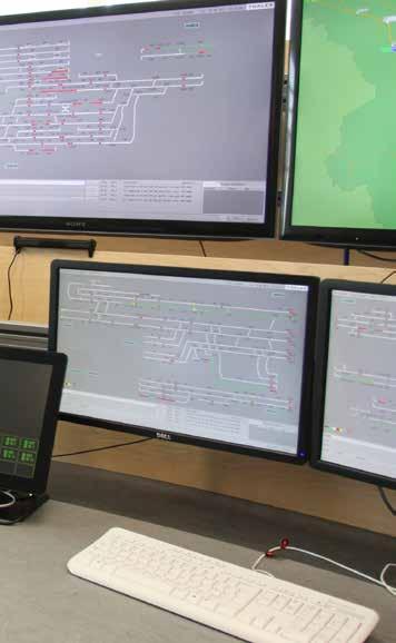
» These are just three examples of what can happen and impact on the operational railway, but other instances exist. More common is hacking of business services that promote train travel, sell tickets, make reservations and suchlike that interface with the travelling public.
THE DIGITAL RAILWAY
A phrase that crops up regularly in technical articles is the ‘Digital Railway’. The term is banded about by many people who do not really understand what it is all about or what is involved. In the past, most railway applications were individual systems, for example radio, customer information, train performance and reporting, all without much connectivity.
With the demand for better information all round, much greater connectivity is occurring as part of the digital transformation, leading to a diverse architecture and an extension of existing architectures. There is a convergence of Information Technology (IT) and Operational Technology (OT) with new dependencies and more access points. Software-based solutions are commonplace, even before the role of Artificial Intelligence (AI) is being considered. All of this is a hunting ground for hackers, whether or not the intent is criminal or otherwise.
REGULATION, LEGISLATION, AND STANDARDS
As can be expected, a host of guidance documentation has been prepared to help and direct organisations into protection measures against cyber attacks. These are at an international, national and railway level. Locating all these and then understanding them can be something of a challenge but much of the guidance amounts to common sense actions. These may not always be obvious until they are pointed out. In all of this it must be remembered that cyber security is a challenge for all rail engineering disciplines and, as is explained later, it is the connectivity of systems that is creating the digital railway. This connectivity is the potential window for hackers to access systems and it must be understood to a much higher degree.
» The Telecommunications (Security) Act 2021 enforced the need for providers of public electronic communications networks and services to take all necessary steps to prevent cyber threats from disrupting communications networks that are vital to the continuance of everyday business in the country. Ofcom has the duty to define the security requirements and to make sure that telecom providers take all necessary steps to comply. While initially aimed at the public telecom operators, the railway must be equally compliant in fulfilling the requirements of the Act. Since the advent of fibre optic cables and associated transmission, the telecoms arm of Network Rail has become the universal ‘pipe’ for many operational applications including signalling and electric traction control.
» Internationally, the subject is led by the IEC (International Electrotechnical Commission) and specifically its group TC9 Electrical Equipment and Systems for Railways. The IEC has been in existence since 1906 so is well established in the field of electrical standards and safety. For cyber security, the document IEC 63452 relating to safety levels for rail operators and suppliers, is embracing cyber security work with a new document IEC 62443 entitled Railway Cyber Security Regulations being produced. It is expected this will be published shortly.
» Nationally, the British Standards Institute (BSI) is co-ordinating and focussing these IEC documents for the UK rail applications. A committee is established to produce a guidance document.
» In Rail, the Rail Safety and Standards Board (RSSB) produces standards that impact on the whole industry and RIS 2700 RST gives guidance on the verification of control measures for engineering change to rail vehicles. From this, standard TN111 details types of cyber security control measures for rail vehicles.
» Within Network Rail the document TS 50701 is derived from IEC 63452 and gives guidance for rail applications.
 PHOTO: ISTOCK.COM/OLEMEDIA
Rail Engineer | Issue 207 | Mar-Apr 2024 51 SIGNALLING & TELECOMMUNICATIONS
If you’re already confused, it wouldn’t be a surprise. Understanding the best means for protecting against cyber attacks can be time consuming and the available documentation is hard to interpret. For rolling stock projects, it has been established that a separate assurance chain is needed from a regulatory viewpoint, hence the emergence of TN111. Rolling stock design and operation contains air gaps, in situ on board systems that link to the outside world, balise readers that link to the signalling system, and a multitude of radio and satellite links that give operational performance information. All these interfaces must be cyber assured.
MANAGING THE IT / OT DIVIDE
Both IT and OT have different assurance regimes, but a number of systems have to understand and manage the differences. The focus for IT is confidentiality of data whereas OT requires integrity and availability. For both of these, the connectivity of systems using telecom and data linkage is vital to the business objectives of the railway and the interfaces that have emerged create the opportunity for security breaches and cause operational limitations. Some of the systems where conflicts of interest may occur are:
» Digital Signalling. Very rarely are such projects undertaken at greenfield sites. As such, the design of a project must be aware of security already embedded in existing systems and designers should beware of assuming that the existing security is both fit for purpose and safe. There is a need to establish
a ‘road map’ to enhance and leverage security capability within the products being used to ensure the security of the eventual project solution. This will involve interfaces across many stakeholders, and it can be difficult to interrogate the security of different manufacturers. Expectations should be shared and agreed with every party at an early stage.
» Traffic Management Systems (TMS). To be effective, TMS must extract and assemble data from many sources, for example timetable data, train describer information, platform planning, rolling stock capability, train crew diagrams, and potential conflicting movements. All of these are vulnerable to cyber attacks which can impact on the resultant train plan. As such, there has to be a compromise between IT and OT that may end up recognising the vulnerability of the final information but without compromising safety.
» Driver Advisory Systems (DAS). Again, a number of inputs are required to produce the correct information as to the way a train is being driven. These include timing points along the railway, the current location of a train (derived usually from satellite positioning), train describer steps, train speed, and potential conflict with other train movements (this will be important for Connected DAS applications). These are all systems that can be accessed and hacked by third parties, and which represent an ever-present risk. It is therefore essential that DAS remains an advisory system and must never replace the information provided by the signalling system.
There will be other systems with multiple inputs that will impact on the business rather than the operational railway and can seriously affect the conducting of day-today business of selling train travel.
FUTURE DEVELOPMENTS AND MONITORING
The current regulatory regime has been mentioned but increased regulation of cyber security for critical infrastructure is on its way. The EU National Infrastructure Security (NIS) Directive is already in being, and the EU Cyber Resilience Act is expected in 2024. Other countries as well as the UK are providing new regulation. These include the USA, Australia, Singapore, and the UAE. All this is fine, but does it further confuse the future situation?
From all of this, there is a need to improve incident reporting requirements and an identification of critical dependencies. Logging and monitoring must be better managed in order to recognise when something is not performing as expected. Vulnerability management must recognise that assets cannot be introduced, proved, and then forgotten. Asset life is also a consideration for railways, especially where systems and products are intended to last several decades. Regular security updates will be needed over the entire asset life. Everyone has a part to play, and regular training on cyber awareness is needed. A positive and open reporting culture should lead to improved leverage and replication of best practice. As in safety practice, volunteer reporting of ‘near misses’ should be encouraged.
PHOTO: NETWORK RAIL
Rail Engineer | Issue 207 | Mar-Apr 2024 52 SIGNALLING & TELECOMMUNICATIONS
THE WAY FORWARD
Rail engineers will understand the V life cycle –requirements, development, design, build, test, integration, commissioning, maintenance, updates, and decommissioning. The V cycle tracks the interaction between these phases as a project progresses. Cyber security impacts on all of them and the people involved in each stage need to understand the risks that could arise.
Achieving this will secure some early wins so everyone should be educated to know:
» Security applies to all staff.
» Consideration of the whole life cycle.
» Establishment of a cyber security culture.
» An understanding of what is out there now and potential exposures.
» Investment in logging and monitoring and how it is practised.
» Knowledge on how to combat attacks and recover from them. More specialised staff must be able to identify data flows, their direction, and concentrations.
If this sounds too generalised and impractical for everyone to take in, then put in place some realistic measures that will help the overall security. Carry out an exercise to create proportionate assumptions which could contain knowing what is most likely to ‘stop the railway’. Determine where the ‘crown jewels’ are, namely the critical elements of running trains and how they can be compromised. Be rational but be organised to manage the architecture of systems through constant live monitoring.
SOME RECOMMENDATIONS
Previous articles on cyber security have detailed the obvious steps to avoid being infected with unwanted intrusion: forbidding staff to use personal USB sticks or disks that might contain malware to access systems; not leaving computers switched on overnight in unmonitored environments; checking the credentials of people who have access to systems especially third parties brought in to carry out updates. It all sounds blindingly obvious but is often forgotten.
More focussed recommendations are as follows:
» Know your ‘bill of materials’ both hardware and software.
» Run ‘day in the life’ exercises and exercises to identify root causes.
» Know the difference between a cyber attack and a software bug.
» Work together to perform incident management.
» Understand the whole life situation including how to carry out patching and updating.
» Know the vulnerability of assets and have an obsolescence plan.
» Plan for graceful transitions.
» Ensure training and documentation is regularly updated.
» Set clear requirements and expectations.
» Understand how a recovery situation will work.
Some of you may find this all a bit much to take in and that is understandable. There will be a need to employ cyber security experts, and larger organisations should already have these in place. Smaller companies should have someone
named for IT management and they will have responsibility for keeping systems safe. This might require calling in further expertise if problems occur.
Work on the basis that an attack will happen rather than believing you have the necessary steps in place and are safe from attack. Big organisations have suffered, for instance the British Library was attacked in 2023 with many of its processes seriously affected. Only now is it recovering from this.
There is no final solution as hackers are constantly finding new ways of accessing systems. Constant vigilance is needed. Above all, take the issues of cyber security seriously and don’t regard it as something that happens to other people.
For more information on cyber security, readers may like to refer to the following Rail Engineer articles:
» Understanding cyber security (issue 189, March-April 2021)
» Cybercrime and security in rail (issue 196, May-June 2022)
Rail Engineer | Issue 207 | Mar-Apr 2024 53 SIGNALLING & TELECOMMUNICATIONS
COMPANY PROFILE

GGP Consult is a privately owned consulting engineering company established in 1994. We are based in the UK on the outskirts of Hull, where our purpose-built offices overlook the famous Humber Bridge. Over the years, we have expanded to include GGPGeo and GGP Survey, with an additional office in York, and we’re shortly due to open another office in South Yorkshire.
We have a 120+ strong workforce with over 1,500 years of collective experience, and have completed 100+ international projects as well as 750 jobs last year alone. Having grown steadily since our formation in 1994, we now provide considerable resources to over 50 countries around the world with a wide range of expertise, including:
» Civil Engineering
» Structural Engineering
» Marine Engineering
» Seismic Engineering
» Mechanical Engineering
» Architecture
» Project Management
» Site Services
» Health & Safety
» Expert Witness
» Fabrication Detailing
WHAT
“...their personable approach and desire to exceed the client’s expectations are what sets them apart from their competitors - we commend GGP for being able to produce the highest quality designs at the most competitive rates...”

 The Rail team is headed by directors Chris Wiles and Brendon Hodgson. Both have over 25 years of experience.
OUR CLIENTS SAY...
ALL PHOTOS PROVIDED BY GGP CONSULT Rail Engineer | Issue 207 | Mar-Apr 2024 54 FEATURE
“I personally think our continued success is due to our professional attitude and our ability to provide a cost effective, innovative and flexible service, using the latest technology to solve problems and deliver economic projects. Each project is treated equally and overseen personally from start to finishwe are very hands on”.
Jim Gabbitas, our managing director & chairman
RAILWAY AND INFRASTRUCTURE SERVICES
With an ever-expanding portfolio of prestigious projects covering thousands of sites and tens of thousands of assets (new and old), our wealth of experience allows us to undertake every aspect of design development from concept to completion. We are also able to offer project management as well as client and agent services, where required. Whether it be lineside civils, lineside structures, stations and depots, temporary works, or level crossings, we can help.
We can also assist with civil engineering, structural engineering, signalling (civils and ground plan design), and architectural services along with many other aspects of multidiscipline design works, arrangement and management (e.g. P-way, M&E, ETE, and OLE). We focus on offering tried and tested cost-effective solutions and strive to be innovative, utilising the latest technologies and techniques - whether it be working in the office or on site - and always with the construction team and end users in mind.

GGP Consult 2 Hallam Road, Priory Park East, Hull HU4 7DY
Tel: 01482 627963
Email: user@ggpconsult.co.uk
https://ggpconsult.co.uk/


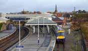
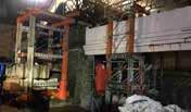
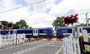

Lineside Civils
GGP Consult have worked on resignalling and capacity relief schemes for some of the UK’s largest rail infrastructure contractors.
Lineside Structures
Our architects and engineering professionals are well equipped to identity and develop designs, tailored to suit the client’s needs.
Stations and Depots
GGP Consult have worked on a wide range of station and depot projects including platform extensions, station refurbishments, and lighting designs.
Temporary Works
GGP temporary works provide support to major contractors and their sub-contractors during the construction phase of their projects.
Level Crossings
Our dedicated level crossing team provides greater resource flexibility and assurance to all of our clients. Works include in-house ground plan designs as well as civil and structural design & site services.
Site Services
GGP operate survey and ground investigation teams to provide greater resource flexibility and assurance to our clients when programme is paramount.
Rail Engineer | Issue 207 | Mar-Apr 2024 55 FEATURE
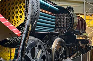
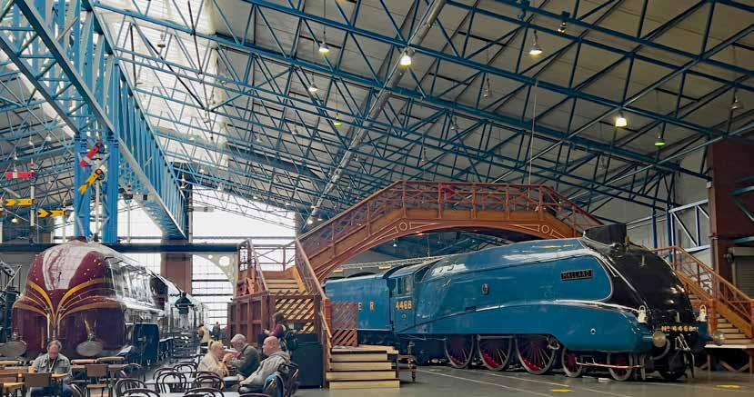
National Railway Museum inspires future engineers
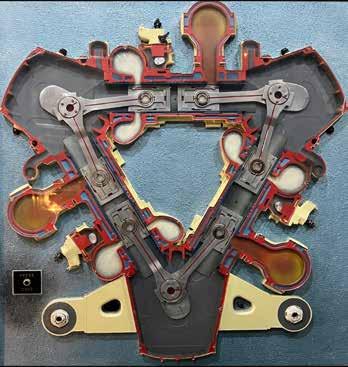
Railway engineers looking at the exhibits in the National Railway Museum (NRM) at York must surely be impressed by their predecessors’ achievements. An example is the museum’s 98-tonne Merchant Navy class steam locomotive which was built in 1949. This is sectioned to reveal how Britain’s last steam locomotives were designed to maximise their thermal efficiency and get the maximum power from their superheated steam.
A further example is the cross-sectional working model of a Deltic diesel engine showing its compact design. This shows how two of these engines could be fitted inside a Deltic diesel locomotive to give it a power output of 3,300hp. One of the museum’s star exhibits, its A4 class locomotive, Mallard, achieved the world record speed of 126mph for a steam locomotive in 1938, though after it did so it had to be sent to a workshop to repair an overheated big end bearing.
The UK certainly has an impressive railway engineering heritage in which there is great interest. The NRM attracts over 650,000 visitors each year whilst heritage railways have over 10 million visitors a year. Yet today’s railway engineering is much more impressive than the museum’s exhibits.
 PHOTO: DAVID SHIRRES
DAVID SHIRRES
Cross section of Deltic engine
Sectioned Merchant Navy locomotive
PHOTO: DAVID SHIRRES
PHOTO: DAVID SHIRRES
DAVID SHIRRES
Cross section of Deltic engine
Sectioned Merchant Navy locomotive
PHOTO: DAVID SHIRRES
Rail Engineer | Issue 207 | Mar-Apr 2024 56 FEATURE
PHOTO: DAVID SHIRRES
RAILWAY ENGINEERING TODAY
The speed of Mallard’s one-off record breaking run is now commonplace with most longdistance passenger trains running at 125mph. Today’s railways are a complex system in which trains, track, signalling, telecoms, and electrification systems have evolved together to form a highly efficient, high-capacity transport system which offers significant benefits because:
» Loads are efficiently distributed – typically a maximum dynamic wheel force of 350 kN gives a rail head pressure of 2.8 kN/mm which is progressively reduced through the rails, sleepers, and ballast to 0.5 N/mm.
» Low resistance to motion – the rolling resistance of steel wheels on steel rails is about 0.1% of the weight of the train compared with about 1% for car tyres on a road. At speed, close coupled railway vehicles have a lower aerodynamic resistance to motion than the same number of individual vehicles.
» High passenger and freight capacity –coupling many vehicles together offers high freight and passenger capacity. HS2 is designed for 18 trains an hour, each with 1,100 seats (i.e. 20,000 passengers per hour). A much wider three-lane motorway carries around 6,000 people per hour.
» Collecting electricity on the move – as part of a guided system, electric trains can receive megawatts of power as it is generated. Hence electric trains are powerful and highly efficient as they do not need to store or convert energy.
» Connectivity – new railways connect into the existing railway network to offer far more journey opportunities than those on the new form of guided land transport.
Today’s railway requires a complex interaction between different railway systems. Maintaining and enhancing such systems is a challenging and satisfying job. Yet the engineering of today’s railway is not that obvious, and, for many, today’s trains are just boxes on wheels. With the industry facing a significant challenge in developing and maintaining a skilled workforce that can keep pace with rapid technological changes, there is an urgent need to attract engineers. To do so, there is a need to demonstrate that railway engineering offers an interesting and rewarding career. Hence it is important to explain what railway engineering entails.
In addition to its exhibits the NRM is doing this with its recently opened ‘Wonderlab: The Bramall Gallery’ and it has a new gallery under construction. To learn more, Rail Engineer was glad of the opportunity to visit the museum to talk to Rob Scargill, lead curator of the planned Railway Futures gallery.
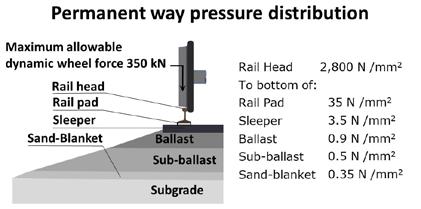
YORK’S RAILWAY MUSEUM
The NRM in York has the largest collection of railway objects in the world which includes over 260 locomotives. It currently attracts more than 650,000 visitors per year despite the ongoing construction work to deliver the masterplan. It was established on its present site, the former York locomotive depot, in 1975. It also operates the Locomotion railway museum in Shildon which has another 120,000 visitors a year. This opened in 2004 and is part of the Science Museum Group.
In 2018, the NRM announced its masterplan designed to increase its visitor numbers by 50%. This will unify the two halves of the museum as Leeman Road, which previously split the museum, is to be diverted as part of the York Central plans. The regeneration of the museum in this way is made possible by the development of the York Central site. This is a partnership between the NRM, Network Rail, Homes England, and York City Council which will provide up to 2,500 homes and 120,000-square-metres of office, leisure, and retail space.

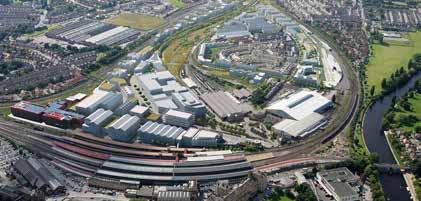
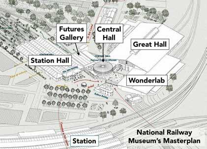 PHOTO: DAVID SHIRRES
PHOTO: NETWORK RAIL
PHOTO: NATIONAL RAILWAY MUSEUM
PHOTO: DAVID SHIRRES
PHOTO: NETWORK RAIL
PHOTO: NATIONAL RAILWAY MUSEUM
Rail Engineer | Issue 207 | Mar-Apr 2024 57 FEATURE
Aerial visualisation of York Central
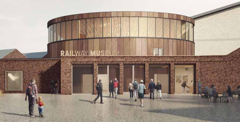
The museum’s masterplan includes a new Central Hall, a Futures Gallery, an interactive Wonderlab experience for families, redevelopment of the Station Hall which was originally York’s main goods station, and a new 2,000-square-metre hall at the Locomotion museum. This will house 47 additional rail vehicles. The NRM considers that this site will then be the world’s largest collection of historic railway vehicles under cover. This new hall will be the hub of celebrations to mark the 200th anniversary of the opening of the Stockton & Darlington Railway in 2025.
As environmental sustainability is an important aspect of the masterplan, there is a site-wide masterplan for energy and carbon reduction. This includes improved insulation, particularly for the Station Hall where the roof is to be replaced with one with much improved insulation. New buildings will have mixed mode ventilation giving natural ventilation in summer and mechanical ventilation with heat recovery in the winter. Elsewhere, more efficient heating systems are being installed.
Around £95 million will be invested to deliver the NRM’s masterplan and associated works to transform its museums at York and Shildon. This is made up of Government funding, Durham County Council funding, surplus museum land sales, industry contributions, and campaign funding. In March, it was announced that the masterplan is to receive a £15 million contribution from the Government’s Levelling Up Fund. This follows a contribution of £18.6 million in 2019 from the Government’s Cultural Investment Fund.
WONDERLAB
July 2023 saw the opening of first part of the master plan, Wonderlab: The Bramall Gallery, after five years in development. This is a purpose-built gallery aimed at children aged 7-14 to inspire them to get hands-on experience of solving engineering challenges to inspire the next generation of rail engineers. It is based on similar Science Museum Group interactive galleries at its Bradford and London museums.
At its opening, NRM’s director Judith McNicol said: “We want to ensure that children have great fun while developing a spark of interest in engineering that will contribute towards tackling the UK’s shortage in STEM skills.”
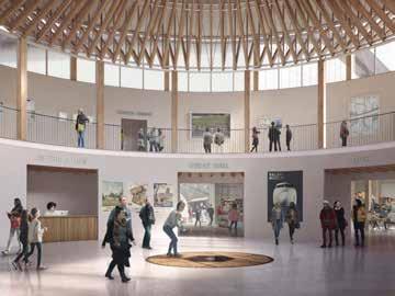
Wonderlab has 18 hands-on interactive exhibits which aim to encourage children to think like engineers and develop skills as they design, build and test to produce different outcomes. This includes a sandpit on which a landscape with railways lines was projected for which children can make cuttings and embankments, and includes a wind tunnel showing smoke trails over different shapes. Your writer managed to build a bridge with loose blocks and saw a thermal imaging camera show a heated brake disc when he applied the brake.

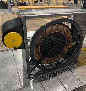
 New Central Hall PHOTO: NATIONAL RAILWAY MUSEUM
PHOTO: NATIONAL RAILWAY MUSEUM Central Hall interior
Heat from friction on a braked wheel shown in a thermal imaging camera
New Central Hall PHOTO: NATIONAL RAILWAY MUSEUM
PHOTO: NATIONAL RAILWAY MUSEUM Central Hall interior
Heat from friction on a braked wheel shown in a thermal imaging camera
Rail Engineer | Issue 207 | Mar-Apr 2024 58 FEATURE
PHOTOS: DAVID SHIRRES

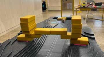
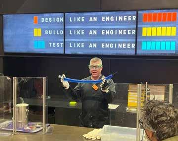

It also has regular demonstrations. One of these showed how carefully mixing fuel, oxygen, and heat can create explosions to power an engine.
RAILWAY FUTURES GALLERY
An important part of the museum’s masterplan is a new gallery adjacent to the new Central Hall which will encourage visitors to consider the role of railways in tomorrow’s transport systems. It won’t predict the future but will encourage visitors to imagine it by asking what they want the future railway to look like. The gallery will encourage visitors to imagine what future departures, journeys, and destinations will look like, and also showcase railway developments outside the UK.
Hence this will stimulate questions such as how journeys will be planned and started; how many passengers and goods travel in the future; what will be the passenger experience; how passenger and freight trains will be powered and maintained; what future train stations will be like; how people will travel to and from stations, and whether there will be better integrated transport.
The gallery will show rail’s extensive impact today and ask visitors to consider its future impact. To do so, visitors will be requested to consider challenges of the future such as the climate crisis, global inequality and energy supplies, as well as timeless railway challenges such as adhesion and capacity. How the railway can help deliver desirable futures will also be considered.
In 2022, Porterbrook announced that it would be supporting the new Railway Futures Gallery with a £2.5 million sponsorship agreement which builds on its decade-long relationship with the NRM. In recognition of this commitment this gallery is now known as ‘Railway Futures: The Porterbrook Gallery’.
A MASTERPLAN TO INSPIRE
In a recent blog, Judith McNicol notes that the invention of the railways was something Britain did for the world. She sees the museum’s masterplan as an opportunity to ensure that the museum is a place for people to engage and get excited by posing questions about the future: What does engineering need to look like and what are its opportunities? What, for a young person, could those opportunities look like?
She feels the museum’s masterplan will inspire “through using the past, homing in on the innovations that have changed the world as a springboard to look at what’s happening today, and the challenges of the future, particularly the sustainability credentials that the railways can deliver in terms of mass transport.”
Though it is natural to reflect on past railway engineering achievements when visiting the museum, it is important to understand how the past can be used to inspire the future. In this respect, the NRM is to be commended for its aim to capture the hearts and minds of the next generation of railway engineers.

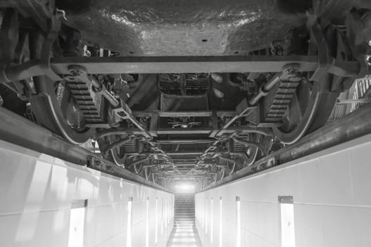
For example, some may worry about the cost of heating for which a railway solution in London is using waste heat from tube trains to provide heating and hot water to more than 1,350 homes, a school, and two leisure centres in Islington. Parents want their children to have exciting meaningful jobs and may not be aware of the need for people with diverse skillsets needed for the many roles that visitors might not associate with railways.
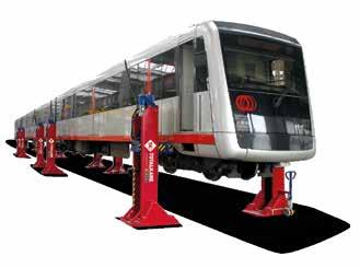
RAIL INSPECTION PITS SAFE INCREASE PRODUCTIVITY QUALITY LIGHTING SERVICING TRAINING LIFTING
lifting and testing equipment for all rail vehicle maintenance.
over 40 years’ experience of high quality, heavy duty vehicle lifting, Totalkare combines world class products with industry leading support to facilitate effective maintenance and repair. RELIABLE SYNCHRONISED
Reliable
With
MOBILE RAIL LIFTING JACKS
PHOTO: DAVID SHIRRES
PHOTO: DAVID SHIRRES
Your writer’s attempt at bridge building
Rail Engineer | Issue 207 | Mar-Apr 2024 59 FEATURE
Wonderlab demonstration
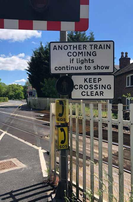
Level crossing safety
Great Britain’s railway level crossings are among the safest in Europe and operate on a network which is one of the most intensively used in the world. However, they still pose a significant safety risk to the public, and trains can be delayed if there is a fault or incident. Level crossings were provided when the railway was built in Victorian times and, if a railway was built today, it wouldn’t include them. The safest level crossing is a closed one, but that is not easy as they connect communities. Rural crossings in particular are increasingly being used for leisure purposes, and there are more deliveries to homes and business than ever.
Covid-19 has changed society. Since the start of the pandemic, people tend to exercise outdoors more often and interest in nature has increased. In July 2020, 46% of people responding to a survey by Natural England said they were spending more time outside than before the pandemic. Visits to the RSPB website have also increased by 69% year-on-year, with 79% of users being new to the website.
The days of the same postal delivery person using a level crossing to access an address are long gone. Shopping habits have changed with people spending more time at home and shopping online. In addition to Royal Mail, there are now a huge number of delivery companies all competing against each other, and time, to meet customer expectations. In rural areas, tractors using crossings are more powerful and faster, and the drivers are located in insulated cabs.
Since 2009, Network Rail has invested over £200 million to close crossings, build bridges, provide new barriers, new warning systems, and new signage. It has also worked to identify new safer rights of way and to educate people how to use level crossings more safely. Over 100 level crossing managers have been recruited and trained to gain a greater understanding of level crossings, the people who use them, and the surrounding communities.
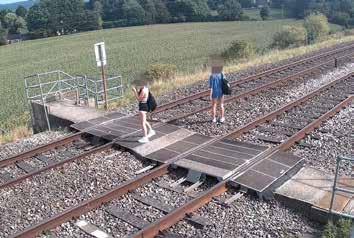 PHOTO: PAUL DARLINGTON
PAUL DARLINGTON
PHOTO: PAUL DARLINGTON
PAUL DARLINGTON
Rail Engineer | Issue 207 | Mar-Apr 2024 60 LEVEL CROSSINGS & TRACKSIDE SAFETY
Charfield level crossing 9 Sept 2023
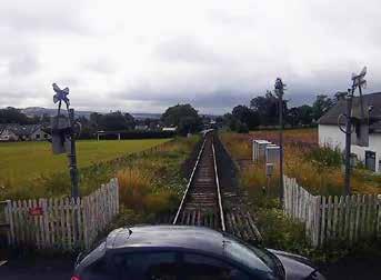
NEAR MISSES AND FATALITIES
The improvements have helped to reduce risk, but there are far too many near misses and sadly there are still fatalities on level crossings. The challenges to improving level crossing safety include the fact that there are more road journeys than ever, a growing population, increasing public demand for leisure train travel, with more services likely to be introduced, and more people using level crossings for leisure purposes. Network Rail says it is seeing a similar number of level crossing incidents, despite having fewer level crossings than five years ago. This means there are more incidents per crossing. When reducing risk at level crossings, the first option is always to consider if the crossing can be eliminated. Replacing crossings with a bridge, diverting the rights of way, or extinguishing the rights away entirely, has enabled Network Rail to close over 1,100 level crossings, but these have been ‘the low hanging fruit’ and closing crossings is becoming more difficult. A grade separated railway is expensive, but Britain is a crowded island and, even if funds and resources were available, in many cases it is not easy to provide grade separation.
There are still over 5,500 level crossings on the network, with the majority being footpath and User Worked Crossings (UWC). UWC’s are those where the user has to operate the gates or barriers for themselves when they want to cross the railway. They may also provide access to private land or property that’s effectively landlocked by the railway.
A passive level crossing is one where the user is required to decide whether or not it is safe to cross. Currently, 70% of all level crossings on the GB network are passive crossings, where users have to look and listen for an approaching train or call the signaller by telephone for permission to cross. This method increases the workload of the signaller, requires the user to contact the signaller, and between them they must correctly confirm that the crossing will be clear in order to allow the user to cross safely. So, telephone crossings are not ideal.
The remaining 30% of level crossings are provided with varying types of warning systems to inform crossing users when it is unsafe to cross. These are known as active level crossings.
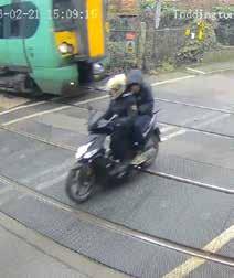
In terms of risk reduction, since 2009, level crossing risk, expressed in terms of Fatalities and Weighted Injuries (FWI), has reduced by around 37% and is currently sitting at around 11 FWI per year. Compared to other European railways, either on the basis of track incidents per track kilometre or by train kilometre, Network Rail has the second lowest number of crossing incidents after Ireland.
However, level crossings still represent around 6% of the system risk on the GB mainline railway. In the reporting year April 2022 to March 2023, there were five fatalities at level crossings, all of which were footpath crossings, demonstrating why the focus on reducing risk at these types of level crossings is particularly important. In addition, near misses at pedestrian level crossings is a continuing trend which is not reducing. So, more has to be done.
LADY HOWARD CROSSING
On Thursday 21 April 2022, a pedestrian was struck and fatally injured by a train at Lady Howard footpath crossing in Surrey. The pedestrian, with a dog and pushing a wheeled trolley bag, started to cross after a train had passed, but was struck by a second train travelling in the opposite direction to the first. The investigation by RAIB found that the pedestrian did look twice in the direction of the second train before starting to cross but was unaware that the second train was approaching when the decision to cross was made. This was because the front of this second train was hidden behind the first train, which was moving away on the line nearest.
RAIB reported that Network Rail had not provided any effective additional risk mitigation, having previously deemed the risk to users to be unacceptable. Network Rail had planned and budgeted to install integrated Miniature Stop Lights (MSL) at the crossing, but a shortage of resource meant that the delivery was delayed. Network Rail had fitted additional warning signs for users and a camera to monitor crossing use, but RAIB said there was little evidence that other effective options to mitigate the risk on an interim basis had been considered.
Burneside near miss
Rail Engineer | Issue 207 | Mar-Apr 2024 61 LEVEL CROSSINGS & TRACKSIDE SAFETY
Toddington near miss
The fatality at Lady Howard footpath occurred on 21 April 2022 and RAIB issued its final report in February 2023. However, as new evidence came to light, RAIB re-opened its investigation in August 2023 and published a revised final report in February 2024.
MSLs were commissioned at Lady Howard crossing in January 2024.
MSLs consist of red and green lights. The green light is lit the majority of the time and indicates that no trains are approaching. When a train reaches the ‘strike in’ point the light automatically changes to red, and an audible alarm sounds to indicate that users must not cross and the closure sequence commences. It is set at a distance calculated to allow users a safe amount of time to cross when trains are travelling at the maximum speed permitted on the line. The audible alarm also includes a spoken warning which is triggered if another train is approaching the crossing soon after the first one has passed. This message states “Warning – another train may be approaching”.
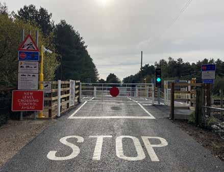
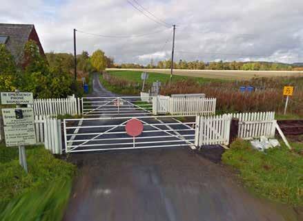
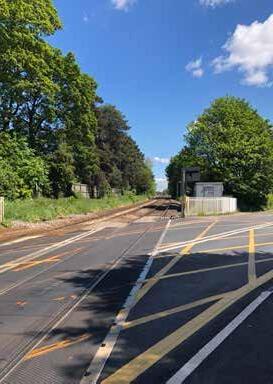
COULD SAFETY BE IMPROVED QUICKER?
The need to install safety improvements does not need to be questioned. Rail Engineer first reported on the Schweizer Electronics MSL eight years ago in June 2016. Schweizer said at the time that its experience in Switzerland was to receive an order on a Thursday, complete the design on the Friday, and install at the weekend. However, it took years to get the product approved for use in GB and Rail Engineer is doubtful if an MSL could be installed in four days here. MSL systems are now being regularly installed and yes, technology needs to be assessed and trialled robustly, and MSL’s interfaced to the signalling system will need design and testing; but could the delivery of safety technology be improved?
In 2015 RSSB reported on the need for a review of signing requirements at private road level crossings to determine the types of signs, signals, and markings that would be most effective in reducing road user errors and violations at these crossings. Rail Engineer reported on the welcome proposals in the article ‘Making user worked crossings safer’ in issue 177 (August 2019), but the new signs have taken years to reach agreement and only passed into legislation with the Private Crossing Signs and Barriers regulations, 2023, eight years after the RSSB report. The legislation currently only covers signs in the English language and work is ongoing with the Department of Transport to develop Welsh language signs. So how long will this take?
The development of the signage has been very much a collaboration between level crossing risk management professionals, human factors experts, and engineers. The signs are heavily pictogram based, to mitigate users potentially not having a detailed understanding of English. Over the next few
Rail Engineer | Issue 207 | Mar-Apr 2024 62 LEVEL CROSSINGS & TRACKSIDE SAFETY
PHOTO: PAUL DARLINGTON
years, Network Rail will be installing the new signs at all private crossings and public footpath level crossings in England and Scotland.
The legislation focuses on defining what the signs look like but doesn’t cover how to use them.
So, Network Rail has produced Module A 28a to the Level Crossing Design Handbook, to set out the application and positioning rules for the signs. This was published in March with a compliance date from April.
INSPECTION AND MAINTENANCE
Level crossings are inspected by a level crossing manager at a frequency based on the level of risk of a crossing. The only consistent factor of a crossing is that everything will be constantly changing! It is therefore important that a check is made for any defects or changes that may pose a risk to users, trains, or vehicles passing over the crossing.
For example, where a passive crossing requires a sighting distance, this can quickly be compromised by vegetation growth, requiring an intervention or even a temporary speed restriction. Network Rail cannot always quickly fell offending trees and may require a site-specific licence. Nothing is easy with level crossings. Even a speed restriction may not be the best way to reduce risk as a longer waiting time may encourage a user to cross in front of a slowmoving train. But even a slow-moving train can’t stop quickly, and users can stumble and lose their balance on a crossing.
The Network Rail maintenance teams undertake a programme of planned maintenance activities, and on some level crossings remote monitoring systems check asset health and performance, to enable timely interventions to tackle emerging defects.
RENEWALS
When level crossing equipment has reached the end of its life cycle, the asset will be renewed. Given the high cost of level crossings and their long service life, it is vital to select the safest crossing equipment most suitable for the site-specific risks. Very often, over the life of a crossing both the railway and the surrounding area, and the risks, may change significantly, and a comprehensive, suitable, and sufficient risk assessment must be produced to identify the right solution.
Automatic Half Barrier Crossings (AHB) were introduced many years ago and, when used properly, are safe and efficient, as the ‘road closed’ time is less than other types of crossing. An AHB is initiated automatically by an approaching train and there is no monitoring to check if the crossing is clear before a train is allowed to cross. As the name suggests, AHBs do not have full barriers, so people can easily ‘weave’ around the closed barriers. AHBs account for just 6% of the total crossing estate but hold 32% of the total level crossing modelled risk, therefore no new AHBs are being installed and measures to mitigate against weaving are being looked into.
HEALTH AND SAFETY STRATEGY
Leading Health and Safety on Britain’s Railway (LHSBR) is the rail industry’s health and safety strategy. Developed by leaders across a range of rail sectors, this strategy sets out the challenges and activities which need collaborative approaches to deliver a better, safer, and healthier railway across Great Britain. The strategy identifies 12 key risk areas where safety and health performance needs to be improved, of which level crossings are one of them.
This requires the industry to research and develop emerging technologies leading to cost effective level crossing upgrades, and to collaborate to deliver consistent messages to the public in relation to level crossings.
In response to LHSBR, Network Rail has produced the report ‘Enhancing Level Crossing Safety 2019 to 29’, which sets out the overarching strategy to manage and reduce level crossings risk, enable effective collaborations, and the delivery of targeted improvements. The document also sets out Network Rail’s goals to reduce safety risk, increase rail capacity and performance, and reduce operational and financial risk. The four key areas are, risk management, technology and innovation, competence management, and education and enforcement.
Society is changing and there is an increasingly diverse population, with potentially more vulnerable people using level crossings. Public attitudes and expectations are changing, and people expect that risks will be designed out of level crossing systems. The public expectation of what is safe enough can also change quickly when things start to go wrong.
New crossing technology can help improve level crossing safety, but level crossing safety cannot be improved by technology alone. Everyone, including government, the rail industry and its supply chain, and wider society, must work together to improve level crossing safety.


All photos credited to Network Rail unless otherwise stated.


- Here to help and support YOU during times of need
for
Registered charity: England and Wales 1160901, Scotland, SC047016 JOIN ONLINE TODAY www.tbf.org.uk TBF24_Advert_185x50.indd 1 01/03/2024 07:23
TBF
A wide range of benefits for you, your live-in partner and dependent children
less than 20p per day .
Rail Engineer | Issue 207 | Mar-Apr 2024 63 LEVEL CROSSINGS & TRACKSIDE SAFETY
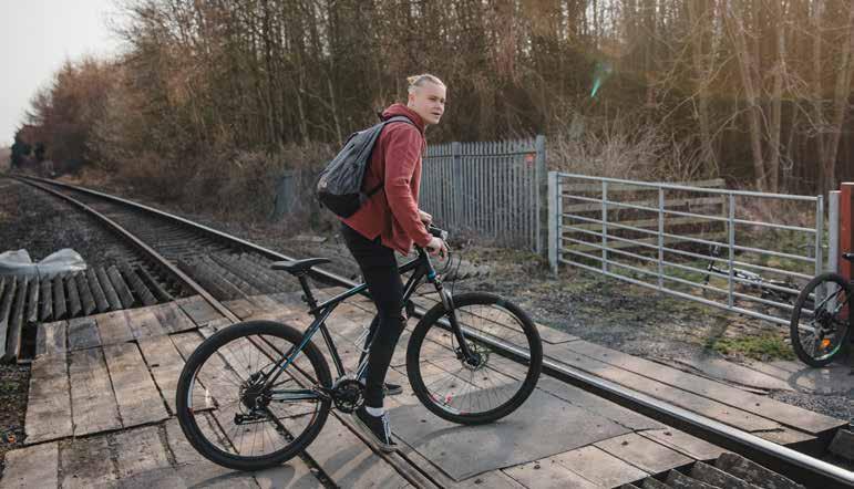
Improving level crossing safety using technology
Jonathan Evans, Network Rail’s technical head of level crossings engineering, recently delivered a presentation to the IRSE Midland & North Western Section, explaining how technology can help to improve level crossing risk management, together with the level crossing engineering solutions being developed by Network Rail. Jonathan explained that his team are part of the technical authority at Network Rail responsible for engineering approval. Colleagues across the wider part of Network Rail, including the level crossing safety teams, Route Services, and partners within the supply chain, also have a vital role in managing level crossing risk explained Jonathan.
WHISTLE BOARDS
The ‘passive’ 70% of all level crossings on the network require a user to stop, look, and listen in order to determine whether or not it’s safe to cross. Whistle boards are provided at many crossings where there is insufficient siting distance, so that as a train approaches it sounds its horn and provides the crossing user with an audible warning to mitigate the lack of visibility. However, it can be difficult to hear a distant train horn, particularly in noisy environments, and train horns are not sounded at night during the nighttime ‘quiet period’ - between midnight and 06:00. Because of this issue, the long-term goal is to eliminate whistle boards for level crossing purposes.
An incremental improvement is to provide a supplementary audible warning system, which detects an approaching train and provides an audible warning at the crossing. The Covtec system uses a radar to detect a train and a wireless comms link between a remote detection unit and the crossing sounder. The system uses ‘off grid’ solar power and is independent of the signalling system. It detects trains and sounds a recording of a train horn at the crossing. The system currently has no specific safety integrity and users are not provided with any visual indication of whether it’s safe to cross or not. Therefore, whistle boards currently have to be retained to guard against system failure and, of course, a sound warning does not assist users with hearing issues.
ISTOCK.COM/SOLSTOCK
PHOTO:
Rail Engineer | Issue 207 | Mar-Apr 2024 64 LEVEL CROSSINGS & TRACKSIDE SAFETY
PAUL DARLINGTON

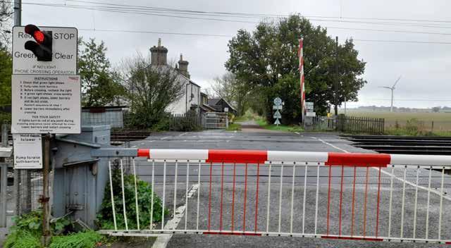
OVERLAY MINIATURE STOP LIGHT SYSTEMS
For many years, footpath and bridleway private crossings have been provided with an audible, visual, active warning solution using ‘miniature’, stoplights. These are called Miniature Stop Light (MSL) crossings. There are different types of MSL system:
» Integrated MSL. These were the original design of MSL and are built into the railway signalling system, which makes them costly and complex to install. However, as they form part of the signalling system, they are suitable for any location, including those where signals and stations lie between crossings and their ‘strike in’ points. A level crossing strike in point is the distance from a level crossing where a train initiates the closure sequence of the crossing. If a train is held at a signal or station, controls are applied to prevent the red light from showing at the crossing until the train is about to start moving again, avoiding excessive warning times.
» Overlay MSL (OMSL). These are separate from the railway signalling system. They can be installed at locations where the railway does not have complex features, such as nearby stop signals. These MSLs use a basic train detection system which detects trains a set distance from the crossing.
» Flex MSL. These use the same technology as OMSL systems but can receive inputs from a signal on each approach to a crossing. This allows them to be installed at locations where trains may be regularly stopped by a signal within the strike in area.
If the time between strike in and the train arriving at the crossing is longer than designed, it can result in red lights being displayed for prolonged periods and/or the OMSL system going into what is known as ‘dark mode’, where the lights at the crossing are turned off until the passage of another train resets the OMSL. Frequent long warning times or occurrences of dark mode are unacceptable as they diminish level crossing users’ faith in, and compliance with, the red and green lights at the
crossing. So OMSLs are not suitable where there are signals which could regularly delay a train’s arrival at the crossing.
However, one of the advantages of the OMSL is to allow for innovation in the form of the type of train detection, such as acoustic detection. There are now around 250 OMSL solutions in use across the network and they’ve made a significant improvement to safety. Further systems are regularly being installed.
The basic principle of the Wavetrain acoustic detection system is that sensors are attached to the rail located at the level crossing, which detect sound waves generated by an approaching train passing through the rails. Locating all of the equipment at the level crossing avoids the need to run cables to remote ‘strike in’ train detection equipment. The system also provides the potential to deliver more consistent warning times, irrespective of the speed of approaching trains. Although with modern, faster-accelerating trains this is not easy.
More traditional systems, which rely on fixed point train detection for ‘strike in’, have to be positioned for the maximum speed, and consequently they can give extended warning times for slower trains. Research has shown that extended warning times can affect the willingness of crossing users to wait.
A single-track version of Wavetrain OMSL is currently on shadow trial in East Midlands, and Network Rail hopes to progress this into an operational trial later this year. A shadow trial is one where the system is essentially fully functional in detecting trains but provides no warnings to crossing users to avoid any issues with it being incorrect while on test.
Originally, the lights for MSLs (as the name suggests) were quite small. They were based on automotive parts with a lens not less than 60mm diameter. Nowadays, MSLs for level crossings use a far larger 200mm diameter and comply with the British Standard for road traffic light signals. They also present a much more visible interface to the user. Network Rail has also developed an interface box to enable the larger units to be retrofitted to older MSL systems to improve their visibility.
PHOTO: NETWORK RAIL
Rail Engineer | Issue 207 | Mar-Apr 2024 65 LEVEL CROSSINGS & TRACKSIDE SAFETY
Currently, OMSL systems are only suitable for locations with simple approaches, usually without signals, junctions, or stations within their striking distance. As more OMSLs are rolled out, attention is turning to innovations that will allow the provision of OMSLs at more complex locations.
This does present challenges, but MSL’s interfaced with the signalling system are on trial at several locations. An interface with the signalling system avoids a prolonged warning which can lead to impatience or misuse. It may also be possible to develop a solution based on measuring the speed of an approaching train and initiate the necessary warning at the optimum time.
POWER OPERATED GATE OPEN
Care is needed when developing level crossing technical solutions to ensure that level crossing safety is improved and not degraded. An example is the Power Operated Gate Open (POGO). This was developed around 15 years ago, as a way of improving the safety and convenience for crossing users by providing buttons on both sides of a crossing to open and close the gates, and to reduce the number of times to cross the railway. Normally, a gated user-worked crossing would need to be traversed five times when crossing with a vehicle. There was also a risk of the gates being left open. The POGO appeared to be a good idea, but unfortunately the early implementations resulted in some near misses. The user expectation was that if the gate opened after a button was operated, then it must be safe to cross. Whereas, in practice, the POGO system had no knowledge of whether trains were approaching or not, as the user was still required to decide whether or not it was safe to cross.
POGOs were removed from use, but there have been a number of developments. POGOs are now used in conjunction with an MSL system with a link between the two systems, such that once the MSL has gone to red, the POGO system will not respond to a request to open the gates. The signage has also been improved; the operating buttons have been made more prominent, together with a yellow surround. It was found that some animals were capable of opening the gates with their tongues!
POWER SUPPLIES
Many level crossings on the GB railway are located in remote locations with no convenient power supply and an active level crossing will need a power supply. Even an IP telephone will need a power supply. Network Rail is therefore developing renewable power solutions using off grid power sources, such as solar and small wind turbines, together with methanol fuel cells to provide continuity of supply when the weather doesn’t supply sufficient power. Several systems are currently on trial.
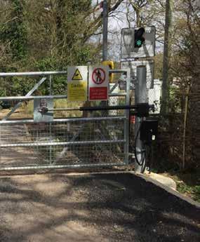
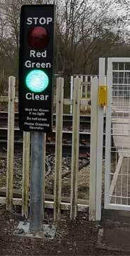 PHOTO: NETWORK RAIL
PHOTO: NETWORK RAIL
PHOTO: NETWORK RAIL
Rail Engineer | Issue 207 | Mar-Apr 2024 66 LEVEL CROSSINGS & TRACKSIDE SAFETY
PUBLIC CROSSING INNOVATIONS
Network Rail is also continuing to improve public road level crossings. There have been a small number of incidents over the years, where the visibility of the barriers has been called into question, resulting in a need for improved barrier boom lighting. New barrier boom lighting is therefore being introduced with the output of the lamps between 30 and 50 candelas, which is about 15 times brighter than the existing lamps, and the size is also being increased to double that of the original.
Another development, aimed at deterring weaving around half barrier crossings by road vehicle drivers, is the use of a retrofit barrier boom extension. The red retro reflective extension narrows the exit width by around half a metre and makes the boom more prominent. It is made from lightweight plastic which doesn’t significantly change the balance of the boom, and if someone felt they were trapped on the crossing they could push the extension out of the way.
The prototype extension has been trialled in some non-operational environments and has received positive stakeholder feedback. Six level crossings at a mix of place types have been identified on the network which will provide experience in a range of different contexts, from straight, fast roads to busy urban settings.
Obstacle detector operated level crossings have been a big success and Network Rail has been working with a new supplier, IDS of Italy, to develop a second generation of obstacle detection systems.
To improve availability and simplify the interface with the level crossing controller, the new system involves just three inputs and three outputs, and overcomes some component obsolescence issues with the first generation system. The new system uses a single radar to provide both the train protection and people protection functions, dispensing with the need for Lidar equipment. Two systems are currently in operational trial service.
ARTIFICIAL INTELLIGENCE
Artificial Intelligence (AI) video analytics is being looked at to support various things, including automating data for level crossing census from CCTV images. This has the potential to reduce the cost of obtaining census data and could make it feasible to monitor crossing usage levels much more regularly than today, which potentially supports improved risk management decisions.
The fundamentals of identifying objects within the crossing area is broadly similar to the crossing clear assist capability but comes with the added challenge of categorising what those objects are, and that is not as easy as might be first thought.
Future areas of development could include a new generation of barrier machines to improve the reliability and performance of current systems, and ways to detect open UWC gates and to encourage users to close the gates. Reducing the cost of level crossing systems also remains a key area of interest. This could possibly include standardised interfaces and more use of PLC based level crossing controllers. Eliminating whistle boards is another longer-term goal.
Work is already under way in Europe to interface level crossings with connected and autonomous road vehicles, and this is an area where technology can further help to improve level crossing risk management and level crossing safety. Jonathan finished by explaining this is another technology his team is looking at to reduce the safety risk of level crossings.

Rail Engineer | Issue 207 | Mar-Apr 2024 67 LEVEL CROSSINGS & TRACKSIDE SAFETY
PHOTO: PAUL DARLINGTON
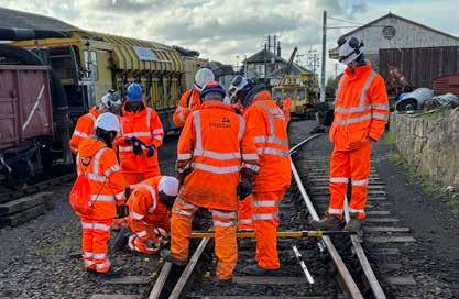
Getting the on track experience
The ‘Practical Track Challenge’ run by the Permanent Way Institution (PWI) aims to give office-based professionals an understanding of the practicalities of track work. This year’s challenge was the seventh such event with the first one being held at the Didcot Railway Centre in 2017. Since then, the event has been hosted at various heritage railways to provide participants with a low risk, on-track, daylight environment. This year’s challenge took place in Scotland at the 8km long Bo’ness and Kinneil Railway.
Visitors to the railway may find it hard to imagine that the first two kilometres of this line, including Bo’ness station, were built on a brown field site between 1979 and 1985. This ‘new’ line runs along the foreshore of the Firth of Forth to the site of Kinneil colliery which closed in 1983. From there, the railway is the refurbished colliery branch line which climbs above the Forth before turning south to join the Edinburgh to Glasgow main line at Manuel.
ORGANISING THE CHALLENGE
The challenge was organised by Andy Steele, PWI’s technical manager, and Jim Watson of the PWI’s Glasgow branch. It was supported by various companies who provided their services free of charge. The principal designer was Systra and the principal contractor was Story Contracting which was supported by Vital Rail. Plant was provided by McCulloch Group, Railcare and Swietelsky Babcock Rail. Cloburn Quarry at Lanark also provided 350 tonnes of ballast free of charge.


Rail (ORR), HS2, Transport for London, the Rail Safety and Standards Board (RSSB), and Network Rail. The PWI offers this event free of charge to its corporate member’s employees. Participants were split into groups which each had the opportunity to visit four sites: Progress Rail: a reballasting site; a resleepering site; and various activities at the Bo’ness yard.
FOUR DIFFERENT EXPERIENCES
The 38 participants at this two-day event came from a wide range of companies which included the Office of Road and
Progress Rail’s South Queensferry foundry is 10km further east along the Forth from Bo’ness. Here, delegates had the opportunity to see how this factory produces cast manganese crossings for Network Rail’s S&C. This included seeing the two five-tonne electric arc furnaces used for steel production and the in-house pattern making. The resleepering site was on the foreshore by Kinneil where the track crosses an oil pipeline from the North Sea to the nearby Grangemouth oil refinery. To do so, it has to cross the pipeline’s protective slab at an acute angle which requires a 200-metre-radius S-curve. The task here was spot resleepering 1 in 3 sleepers. This replaced about 60 obsolete F19 concrete sleepers that have Spring Hook Clip (SHC) fastenings with F23 sleepers having Pandrol clips as the SHC fastenings are not suitable for such sharp curves. The S-curve was then given a design tamp.
The 200-metre curve
PHOTO: HANNAH PERRSON
PHOTO: DAVID SHIRRES
DAVID SHIRRES
Old SHC clip (left) and new Pandrol clip (right)
Rail Engineer | Issue 207 | Mar-Apr 2024 68 LEVEL CROSSINGS & TRACKSIDE SAFETY
PHOTO: DAVID SHIRRES
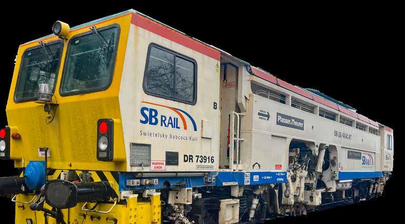
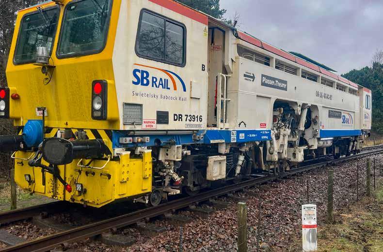
Reballasting was undertaken in a steep cutting, five kilometres from Bo’ness where the line has some drainage issues. Access to this site was made possible by steps provided by VPA. This location also had thin ballast which made it difficult to maintain the track level with good top alignment. For the track challenge, 10 track panels with a total length of 180-metres were reballasted. The track was lifted using McCulloch Panel Lifters, after which old ballast was removed and the track bed levelled. After the track panels were replaced, ballast to the site was delivered by a road rail excavator with two trollies that made several runs from lineside stockpile at Bo’ness. The excavator then positioned it ready for its design tamp.
At the Bo’ness station area, participants assisted the regauging of points which required baseplates to be removed and the replacement of rotten bearers. Baseplate holes were plugged with a DWG Spikefast resin. Slide chairs and fishplates had 40 years of black grease removed and were reoiled with Interflon and fitted with Staytite bolts. Participants then hand compacted new ballast utilising Robel vertical tampers supplied by Torrent Trackside.
At Bo’ness there were display stands provided by CIRAS, McCulloch Group, Staytite, Torrent Trackside, Pandrol, and Robel where battery powered tools were on display. This included a rail saw that can make 16 cuts on a single charge.
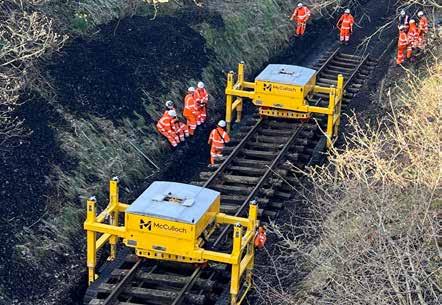
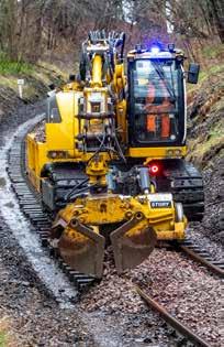
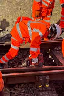 PHOTO: HANNAH PERRSON
PHOTO: DAVID SHIRRES
PHOTO: DAVID SHIRRES
PHOTO: DAVID SHIRRES
Ballast placement Fixing S&C baseplates
McCulloch panel lifters
PHOTO: HANNAH PERRSON
PHOTO: DAVID SHIRRES
PHOTO: DAVID SHIRRES
PHOTO: DAVID SHIRRES
Ballast placement Fixing S&C baseplates
McCulloch panel lifters
Rail Engineer | Issue 207 | Mar-Apr 2024 69 LEVEL CROSSINGS & TRACKSIDE SAFETY
Swietelsky Babcock Rail’s 08-16 4X4CRT tamper tamping the reverse curves
ON-TRACK PLANT
The use of a RailVac machine to extract ballast from S&C in the yard at Bo’ness was demonstrated. This on-track plant has a ballast vacuum extraction system to remove material between rails and sleepers without the need to remove them. The use of this machine avoids damage to other infrastructure such as cables and pipes. It is intended for use in areas where it is difficult to use standard excavators and can be quickly set up on site so operates efficiently in short possessions. Under its own power it can only travel at 20 km/h so it needs locomotive haulage during main line transits. The RailVac was built, and is operated by, Railcare AB which operates similar machines in Sweden.
Prior to its use at the resleepering and reballasting sites, a Swietelsky Babcock Rail 08-16 4X4C-RT tamper was on display at the Bo’ness station platform. This was built by Plasser and Theurer in 2000 and can tamp 440 metres/hr. It has four split head tamping units with a total of 16 tines. These units can be moved independently from each other which enables it to tamp most S&C units. Adjacent to the tamper unit is a track lifting frame with flanged rollers to grip the track. On board the tamper there is the opportunity to sit in both operator positions, one in the driving cab and one above the tamping units. Network Rail’s Neil Wightman explained how the driving cab operator controls the movement of the machine whilst the other operator controls the tamping units. Neil explains how the tamper measures track line, cant, and level prior to tamping using trolleys at the front, centre, and rear of the machine. The tamper’s computer then determines how the track needs to be adjusted for the optimum alignment. This is maintenance
tamping. An alternative approach is design tamping, when a previously developed track design is input to the tamper’s computer which then computes the difference between this design and the measured track.
Both the reballasting and resleepering sites had design tamps for which the track geometry files, as well as surveying services prior to the event, were prepared by a team led by Graham Hutchinson of Network Rail.
A WIN-WIN EVENT
The PWI packed a wide variety of track experiences into this twoday track challenge and are to be congratulated for organising and funding such a worthwhile event. It is a great way of developing railway engineers who would otherwise not get the chance to get up-close to trackwork and its associated plant and equipment.
Participants came from a wide variety of backgrounds who, whatever their role, will no doubt benefit from their exposure to the practicalities of track engineering. The event also gave participants the opportunity to learn from each other and form networks with those who they would otherwise not meet. Your writer, who is not a track engineer, certainly learnt much from this event.
The many companies which freely supported this event deserve credit, as do the PWI members who provided support and guidance on site. The Bo’ness and Kinneil railway’s cafe also provided excellent hospitality and the opportunity to visit its impressive museum.
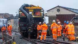
Last but not least, the event left the railway with some much-improved track. The track challenge is certainly a good opportunity to support the heritage rail community. All in all, this challenge was a win-win event for all concerned.
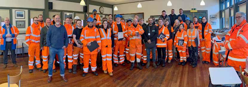 Railvac removing old S&C ballast
Tamper control cab
The tamper’s tines and track lifting frame
Participants and organisers
PHOTO: DAVID SHIRRES
PHOTO: DAVID SHIRRES
PHOTO: DAVID SHIRRES
Railvac removing old S&C ballast
Tamper control cab
The tamper’s tines and track lifting frame
Participants and organisers
PHOTO: DAVID SHIRRES
PHOTO: DAVID SHIRRES
PHOTO: DAVID SHIRRES
Rail Engineer | Issue 207 | Mar-Apr 2024 70 LEVEL CROSSINGS & TRACKSIDE SAFETY
PHOTO: DAVID SHIRRES


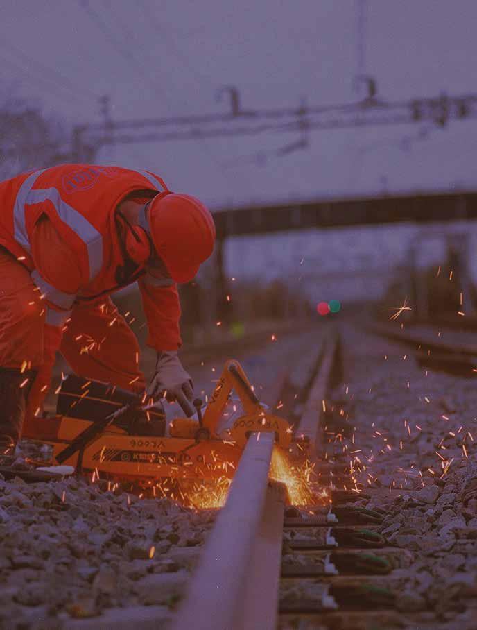


vital.uk.com 0161 836 7000 info@vital.uk.com
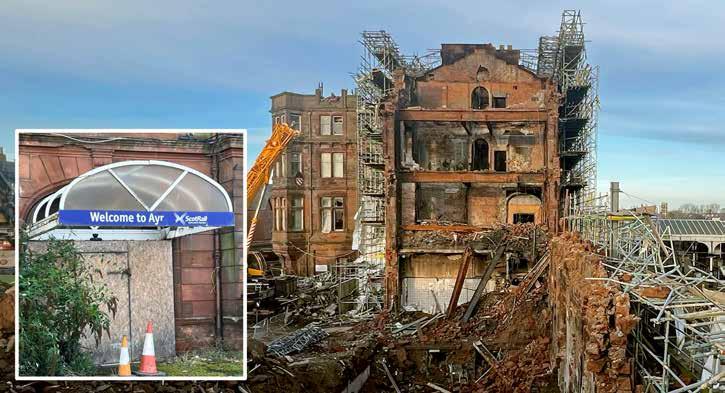
Ayr hotel fire closes railway for eight months
The impressive grade-B listed Ayr Station Hotel was built in 1885 in the French-Renaissance château-style and was an integral part of the station with the travel centre inside the hotel’s north wing. In 2010, it was purchased by a Malaysian businessman who abandoned it after it closed in 2012. With the hotel not being maintained, the following year South Ayrshire Council issued a Dangerous Building Notice (DBN). In response, Network Rail erected crash decks over the station entrance and to protect platforms by the hotel.
THE 2018 DBN
The building continued to deteriorate as the council unsuccessfully attempted to contact the hotel’s owner. As Rail Engineer reported in December 2018 (issue 170), in August that year, the council issued a further DBN and declared an exclusion zone around the hotel. Services from Glasgow were then short-formed and those between Stranraer and Ayr were suspended. After the hotel had been encapsulated and other work done, trains to Stranraer resumed in November and the normal train service to Glasgow resumed in December. This exclusion zone also closed the travel centre which was replaced by an outside ticket office in a portacabin.

Since then, the Council unsuccessfully continued to attempt to contact the absent owner and seek recompense from him through the British and Malaysian courts. In 2021, Transport Scotland commissioned a study to identify options for an economically viable future for the Station Hotel building. There were also strong representations from groups who wished to see the hotel restored to its former glory. Nevertheless, due to its unsafe condition, in December 2022 the council decided that the hotel’s south wing had to be demolished. At its September 2023 meeting, the council was advised that surveys were being undertaken so that a detailed programme of works for this demolition could be finalised. It was expected that this programme would be completed in February 2024.
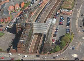

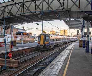 PHOTO: DAVID SHIRRES
DAVID SHIRRES
PHOTO: NETWORK RAIL
PHOTO: DAVID SHIRRES
PHOTO: DAVID SHIRRES
Ayr station 6th February 2024
Ayr station prior to the August 2018 DBN
Ayr Station Hotel on 18th November 2018 with scaffolding erected on south wing
PHOTO: DAVID SHIRRES
DAVID SHIRRES
PHOTO: NETWORK RAIL
PHOTO: DAVID SHIRRES
PHOTO: DAVID SHIRRES
Ayr station 6th February 2024
Ayr station prior to the August 2018 DBN
Ayr Station Hotel on 18th November 2018 with scaffolding erected on south wing
Rail Engineer | Issue 207 | Mar-Apr 2024 72 FEATURE
After 2018 DBN, it was possible to run 4-car electric trains to Ayr
Yet, in the five years since the 2018 DBN notice, the situation at Ayr station remained unchanged whilst £69,000 per month, totalling around £4 million over this time, was spent on scaffolding costs.
HOTEL FIRE

Matters changed dramatically on 25 September 2023 when an arson attack started a serious fire which left the building in a hazardous state. Train services were immediately suspended and the road by the hotel was closed. Trains from Glasgow were terminated at Prestwick and a reduced service ran between Girvan and Stranraer until the diesel units required maintenance and were unable to return through Ayr station to their depot.
The resultant exclusion zone was larger than the one declared in 2018 when it was still possible to run four-car electric trains from Glasgow to the station. After the 2023 fire the station was completely shut for 10 weeks until it was possible to introduce a shuttle two-car diesel unit service between Prestwick and Ayr in December. Glasgow to Ayr trains are normally seven-car electric multiple units.
A contractor started work to make the hotel safe in October. By December, the south wing had been demolished to the extent necessary to open the adjacent road. In January, the council advised that this work would continue until in mid-March when it was expected that train services would be able to resume. However, on 5 March it was announced that a severely damaged wooden supporting beam in the north wing had been discovered.
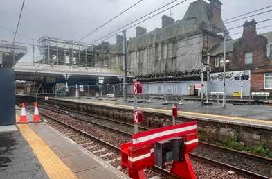
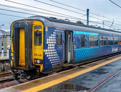
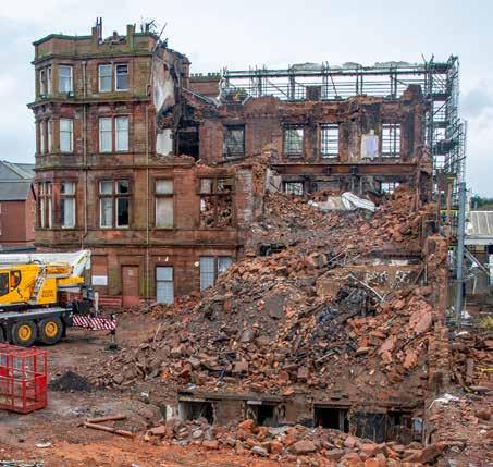
Once sufficient demolition work has been done to enable the exclusion zone to be lifted, Network Rail’s engineers will have to inspect the unused lines to confirm their safety. ScotRail have also warned that drivers will require route retraining which would further delay for the resumption of services. As a result, according to the National Rail website, disruption to rail services is now expected to continue until 2 June. It is now over 10 years since South Ayrshire Council issued its first DBN. During that time the station has become increasingly unsightly, passengers have had to buy their tickets in the open, and the train service has been seriously disrupted. In 2017/18, 1.67 million passengers used Ayr station. The following year, this number was reduced by 200,000 after the disruption from the 2018 DBN. The disruption following the September fire will also have significantly reduced passenger numbers.
 PHOTO: DAVID SHIRRES
 PHOTO: DAVID SHIRRES
PHOTO: DAVID SHIRRES
PHOTO: DAVID SHIRRES PHOTO: DAVID SHIRRES
only 70 metres available on one platform this is the end of the line
the
With
for
Prestwick shuttle
2-car class 156 DMU at Ayr on the Prestwick shuttle
Rail Engineer | Issue 207 | Mar-Apr 2024 73 FEATURE
South wing of hotel almost fully demolished on 15th March 2024
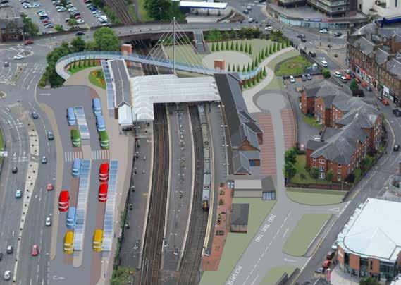
Ayr is a seaside town that attracts many visitors who could well be put off visiting the town for its lack of an attractive rail service. There are also concerns of a significant reduction in numbers coming to the town for the Scottish Grand National in mid-April, and a two-day music festival in early May. It would seem clear that the condition of Ayr Station Hotel has had a significant adverse effect on the town’s economy.
THE LAW

Yet what could the cash-strapped council have done with this Grade B listed hotel when faced with an unresponsive overseas owner? The council has exercised its powers under section 29 of the Building (Scotland) Act 2003 which gives local authorities an obligation to carry out whatever work is necessary to protect people and property adjacent to a dangerous building, and recover associated costs from the owner.
However, if, as in this case, the dangerous building is listed, the council can’t legally remove any more of the structure than is absolutely necessary. Yet section 21 of the 1997 Planning (Listed Buildings and Conservation Areas) (Scotland) Act allows planning authorities to revoke listed building consents as they consider expedient. The council appears not to have considered this option.
Network Rail could also have applied to the Cabinet Secretary for Transport for consent to invoke section 15 of the 1842 Railway Regulation Act to compulsorily acquire the hotel and deal with it. However, this would make Network Rail entirely liable for the hotel.
THE FUTURE STATION
In January, South Ayrshire Council launched a consultation exercise on its Ayr Town Centre Framework plan which includes five specific projects to improve the town centre, one of which is a new station and transport interchange. This is one of the options from the Transport Scotland study on the future of the hotel and station. The proposed station offers easier access from the town centre by a new footbridge over the site of the nowdemolished south wing of the hotel. To create a new transport interchange the town’s bus station is to be moved adjacent to the station. It is envisaged that this new interchange will open in 2028.
The graphic of the new interchange shows that, except for the south wing, the hotel buildings will be retained. However, with the recent announcement on the condition of the north wing, it seems quite possible that this will also be demolished.
The new station will certainly be a huge improvement. Yet in the meantime it seems Ayr’s normal train service will not resume until at least eight months after the hotel fire. Having an adjacent dangerous building shut the railway for eight months is surely unprecedented and it is difficult to imagine that this situation would have been tolerated had it occurred next to a major rail route.
No doubt there are lessons from the sad saga of Ayr’s Station Hotel. Any such lessons need to be shared throughout the rail network to avoid a lengthy suspension of rail services should a similar situation occur elsewhere.
 PHOTO: SOUTH AYRSHIRE COUNCIL
Rail Engineer | Issue 207 | Mar-Apr 2024 74 FEATURE
Proposed transport interchange at Ayr station


What is RailwayPeople.com?
RailwayPeople.com is the largest dedicated rail job board in the UK.


How can it help me?
With the top career opportunities updated daily, your next move is a fingertip away.
What should I do?


Visit RailwayPeople.com today to find your next role and become an essential part of the UK’s rail industry to help the nation build back better.


Rail Engineer | Issue 207 | Mar-Apr 2024 75 CAREERS Find your role! visit: www.RailwayPeople.com / email: rp@rail-media.com / telephone: 01530 816 450
updatedroles daily
Job

SIEMENS MOBILITY
People you can trust with rail transformation
We understand that collaboration across the rail industry is crucial for reducing cost and driving transformation.
siemens.co.uk/mobility
