by rail engineers for rail engineers
NOV-DEC 2025 – ISSUE 217
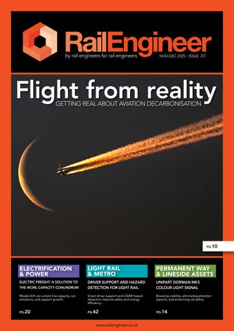
Flight from reality GETTING REAL ABOUT AVIATION DECARBONISATION
PG.10
ELECTRIFICATION & POWER
LIGHT RAIL & METRO
PERMANENT WAY & LINESIDE ASSETS
ELECTRIC FREIGHT: A SOLUTION TO
DRIVER SUPPORT AND HAZARD DETECTION FOR LIGHT RAIL
UNIPART DORMAN MK3 COLOUR LIGHT SIGNAL
Modal shift can unlock line capacity, cut emissions, and support growth.
Smart driver support and LiDAR hazard detection improve safety and energy efficiency.
Boosting visibility, eliminating phantom aspects, and enhancing rail safety.
PG.20
PG.42
PG.14
THE WCML CAPACITY CONUNDRUM
www.railengineer.co.uk
Synthetic S l e e pe r Simply working & sustainable
S U S TA I N A B I L I T Y
R A I LW AY T E C H N O L O G Y
State of the Art
SEKISUI CHEMICAL GROUP: Enhancing Lives, Preserving the Planet. At Sekisui, we’re dedicated to advancing the quality of life worldwide while championing the protection of our planet.
SEKISUI CHEMICAL GmbH Patrick Childs T: +44 (0) 7966 598 055 E-Mail: childs@sekisui.de www.sekisui-rail.com
14 CONTENTS 06| 08| 09|
3
WDF Digitalisation Forum: driving the future of rail
Infrastructure managers, suppliers, and technical specialists gathered for three days of collaboration in Vienna.
Railway Mission reception highlights mental health needs
A new mental health training scheme for rail staff was unveiled at the House of Commons.
Renewing Scotland’s trains
Transport Scotland reveals its plan to deliver improved, more efficient services for rail passengers.
18 20
10| 14| 18| 20| 24| 32| 38| 42|
64
Flight from reality: getting real about aviation decarbonisation David Shirres asks the hard questions about the Government’s plans to decarbonise air travel.
Unipart Dorman Mk3 colour light signal
Modern LED colour light signals improve visibility, prevent phantom aspects, and keep railways safe.
Can connectivity transform rail operations today? Siemens Mobility explains how today’s technology can unlock tomorrow’s digital benefits without the long wait.
Electric freight: a solution to the WCML capacity conundrum
David Shirres examines how electric freight can unlock line capacity, cut emissions, and support growth.
Railway 200: 183 years of UK railway electrification
We track 183 years of UK railway electrification, from early experiments to modern policy challenges.
Managing cracks and fractures on trains
Discover how rail manages cracks and fractures using standards, data, monitoring, and condition-based maintenance strategies.
Railway 200: 162 years of the Underground – 1970 onwards
Malcolm Dobell explores five decades of Underground evolution including the projects he’s been involved with.
Driver support and hazard detection for light rail Research shows how smart driver support and LiDAR hazard detection improve safety, consistency, and energy efficiency.
46| 50| 54| 58| 64|
Inside a Rail Operations Centre
Clive Kessell visits the York ROC and explains the huge benefits offered by such facilities.
Introducing ETCS to the GWML
Explaining the background and difficulties of the project to introduce ETCS on the line to Heathrow.
RIA SigEx 2025
The conference considered signalling innovations, cost reductions, and practical solutions to improve safety and efficiency.
RIA’s conference looks to the future
RIA’s annual conference explored rail reform, GBR, investment priorities, and future collaboration across the industry.
Attracting the next generation of engineers
Paul Darlington explores how rail must modernise and embrace digital skills to attract future engineers.
Rail Engineer | Issue 217 | Nov-Dec 2025
EDITORIAL EDITORIAL
Scientific and engineering realities
Rail Engineer | Issue 217 | Nov-Dec 2025
The WCML is amongst Europe’s British Rail busiest mixed traffic railway. Yet 1974 advert. its capacity is reduced by mixing 125mph passenger trains with slow diesel freight trains that can barely manage 20mph over Shap and Beattock summits. As shown by our ‘Electrifying Freight’ feature, WCML capacity could be increased by hauling freight trains with electric locomotives which, if they could run at 90mph, would eliminate the timetable conflict between freight and passenger trains. Although WCML is an electrified railway, most of its freight trains are diesel hauled due to power supply limitations and the lack of end-to-end electric freight routes. In this respect, electrifying the 6km line to London Gateway, which has over 40 trains a day, would support additional WCML electrified freight. Investing around £15 million on this freight infill electrification would benefit both rail freight and passenger businesses. Achieving the UK’s legally binding commitment to reach net zero GHG by 2050 requires the nation’s transport to be weaned off its annual consumption of 50 million tonnes of petroleum. This is a huge problem as, by weight, batteries have a twentieth of a diesel vehicle’s energy carrying capacity. As we explain, achieving aviation net zero by 2050 is almost certainly an impossible challenge as proposals in the government’s Jet Zero Strategy (JZS) are not credible. This is because it does not consider the costs or practicalities of its proposals, nor does it follow the recommendations of the independent Climate Change Committee. The JZS’s proposals such as sustainable aviation fuels (SAF) are well publicised, yet JZS accepts that such aircraft carbon reduction measures will only reduce aircraft GHG emissions by 36%. Moreover, fuelling all planes by SAF biofuels could require half the UK’s agricultural land. It is not generally understood that government policy is that the residual 64% of GHG emissions to be sucked out of the air. As we show, doing this by offsets would require the creation of a forest of trees covering an area of Surrey, Sussex and Kent combined plus Direct Air Carbon Capture and Storage (DACCS) which has not been used anywhere at scale. Although Government supports the uptake of public transport and active travel, there is little emphasis on modal shift. Furthermore, with the Midland Main Line (MML) electrification 'paused' there is little appetite for rail electrification. In contrast the devolved administrations in Wales and Scotland have specific policies on modal shift.
PHOTO: BRITISH RAIL
Railways are inherently highly energy efficient and have a unique ability to use high-powered electric traction. This makes them a particularly carbon friendly transport mode. Greenhouse gas (GHG) emissions per passenger from a domestic flight are 27 times those of an electric train. Per tonne km, HGV GHG emissions are respectively around 15 and 4 times those of electric and diesel freight trains. Modal shift to rail can therefore reduce GHG emissions as well as offer other benefits such as reduced in energy use and road congestion. However, a significant shift to rail requires additional rail capacity. The M6 in the Midlands and the M74 in Scotland carry respectively 16,000 and 6,000 HGV movements per day. Much of this traffic should be carried by rail, yet there is no capacity on the West Coast Main Line (WCML) for it. Powers to construct HS2 phase 2a to provide much needed capacity expire in February, sadly it seems doubtful whether they will be extended. PHOTO: MDS TRANSMODAL
4
5
THE TEAM Editor
Despite the benefits of electrification, the only example of a UK rolling programme was the Southern Railway's 3rd rail electrification programme between the two world wars.
David Shirres editor@railengineer.co.uk
Production Editor Matt Atkins matt@rail-media.com PHOTO: DAVID SHIRRES
Transport Scotland also recognises that electrification offers whole life benefits and so, in the past 15 years, has increased Scotland’s electrified rail mileage from 23% to 40%. Its recently published proposals to replace the aging two thirds of its rolling stock fleet include a long-term aim to electrify lines that carry freight. Our Railway 200 feature about rail electrification is a tale of both achievements and lost opportunities which explains why the UK only has 38% of its network electrified compared with the European average of 56%. Moreover, UK electrification has been delivered in a highly inefficient manner due to the historic government boom and bust authorisation of electrification schemes. We conclude another Railway 200 feature on the history of the London Underground following part 1 in Issue 214. This shows how technology, politics, and finance have combined to influence the development of London’s Tube network which continues to stimulate London’s economy. The engineering challenges of managing cracks and fractures on trains are described by Malcolm Dobell. His informative feature includes consideration of applicable standards, aerospace practice, TfL’s Case for Continued Safe Operation process, freight fleet maintenance, aluminium metallurgy and vibration monitoring. Challenges faced by signal engineers to improve efficiency and safety while reducing costs are considered by Paul Darlington in his report on the Rail Industry Association (RIA)’s Control, Command and Signalling (CCS) conference, SigEx 2025. This considered cost reductions from the use of Commercial Off The Shelf systems, repetition of standard
DAVID SHIRRES
solutions and the reduction of design and verification costs. Introducing ETCS on the line to Heathrow cost triple the original estimate. We explain the background and difficulties of this complex project which was the first UK main line ETCS fitment. It is essential that the lessons learnt from this project are shared for future ETCS schemes. In the 1960s/70s, the introduction of Power Signal Boxes improved train regulation by providing a wide view of train movements. Their 21st century equivalent are Regional Operation Centres (ROCs) which incorporate all rail operational activities into a single building and show train movements on screens to provide an even wider view. Clive Kessell visited the York ROC and explains the huge benefits offered by such ROCs. We also describe how emerging technology and aspects of main line signalling could be used on trams. This includes the use of Intelligent Obstacle Detection Systems and Smart Driver Advisor Systems to minimise energy consumption. RIA’s annual conference was certainly topical as the Transport Secretary addressed the event immediately before presenting the Government’s Great British Railways (GBR) Bill to Parliament. We report on how she, and others at the conference, discussed the issues associated with the creation of GBR. When considering the complexities of railway engineering, it is possible to forget the people who make the railway work. Hence, we are glad to report on the work of the Railway Mission who do much to support rail workers in challenging situations. We also have an article considering how the industry can attract the next generation of engineers. With the festive season fast approaching, on behalf of all who produce Rail Engineer, I would like to wish our readers a happy and safe Christmas, especially for those working on the railway over the holiday period.
Production and design Adam O’Connor adam@rail-media.com
Engineering writers bob.hazell@railengineer.co.uk bob.wright@railengineer.co.uk clive.kessell@railengineer.co.uk david.fenner@railengineer.co.uk graeme.bickerdike@railengineer.co.uk malcolm.dobell@railengineer.co.uk mark.phillips@railengineer.co.uk paul.darlington@railengineer.co.uk peter.stanton@railengineer.co.uk
Advertising Craig Smith craig@rail-media.com
Rail Engineer Rail Media House, Samson Road, Coalville Leicestershire, LE67 3FP, UK. Switchboard: 01530 816 444 Website: www.railengineer.co.uk
Rail Engineer Videos http://rail.media/REYouTube
Editorial copy to Email: news@rail-media.com
Free controlled circulation Email: subscribe@rail-media.com
The small print Rail Engineer is published by RailStaff Publications Limited and printed by PCP Ltd. © All rights reserved. No part of this magazine may be reproduced in any form without the prior written permission of the copyright owners. Part of:
RAIL ENGINEER EDITOR www.rail-media.com
Rail Engineer | Issue 217 | Nov-Dec 2025
6
NOTICES
Wayside Digitalisation Forum WDF: DRIVING THE FUTURE OF R AIL Digitalisation is rapidly reshaping how railways are monitored, managed, and maintained, and the need for shared understanding across borders has never been greater. Against this backdrop, the Wayside Digitalisation Forum 2025 in Vienna, Austria offered a dedicated platform for infrastructure managers, suppliers, and technical specialists to explore the latest developments in digital signalling and wayside technology. Bringing together a broad mix of international expertise, the event set out to compare practical experiences, examine emerging standards, and discuss the organisational changes needed to support modern, interoperable systems. What followed was three days of open dialogue, technical depth, and forward-looking collaboration.
Rail Engineer | Issue 217 | Nov-Dec 2025
Spanning three busy days from 15 to 17 October, the forum focussed on how digital technologies are reshaping signalling systems and wayside infrastructure, drawing major rail operators, technology providers, system integrators, and specialists from across the globe. Delegates emphasised the benefit of exchanging practical insights from digitalisation projects worldwide, with particular attention to cross-border standardisation and the reduction of system complexity.
Inspiring interactions Technical sessions were structured around multiple themes, covering digital signalling, system architecture, predictive maintenance, and cross-system integration. Presenters from Europe, North America, Asia, and Australia shared a wide range of experiences, giving the audience a global view of the hurdles and possibilities of digital signalling modernisation. Each programme stream included generous breaks, creating ample space for informal conversations and networking. Highlights of the event included: » Digital Interlocking as a platform for ETCS rollout, featuring insights, from DB InfraGO’s Donauwörth project amongst others. » EULYNX and modular signalling architectures, addressing how standardisation enables a flexible, interoperable future, emphasised in a presentation from the EULYNX consortium and others. » Predictive maintenance and digital twins, presented by ÖBB and international technology partners. » Monitoring and diagnostics, with contributions from Network Rail, KONUX, and others. » Operational value through digital diagnostics, including best practices from Infrabel.
NOTICES
Reducing compexity One of the most popular topics throughout the forum was how standardisation – particularly through initiatives like EULYNX – can make signalling systems interoperable across borders while reducing engineering and operational complexity. “We had challenging discussions about this in both panels,” said Michael Leining, managing director at Nextrail, who moderated the two panel discussion sessions on stage. “System integration was the other big topic that we were speaking about,” he added. ”There are challenges for all the infrastructure managers as well as suppliers to handle system integration when it comes to standardisation.” All participants emphasised that digital transformation requires not only technological advances but also organisational and regulatory alignment.
A signal of success The Wayside Digitalisation Forum 2025 was a resounding success – a testament to the sector’s collective commitment to progress – and fostered an exceptional atmosphere of collaboration and openness. Participants valued the technical depth of the sessions as well as the cross-industry networking opportunities the event presented, that will help accelerate global efforts to digitalise railway infrastructure. The message from Vienna was clear: the digital transformation of rail signalling is well underway, and collaboration across industries and borders is the key to making it a sustainable success.
UK rail news as it happens.
Daily email update.
“With WDF Vienna 2025, our ambition was to bring the global wayside community together and elevate the conversation on digital signalling,” said Christian Pucher, programme director at WDF. “The engagement, debate, and openness we experienced exceeded all expectations. The next challenge is to translate ideas into action – and shaping the future of signalling – together.”
Latest rail video.
Over 15,000 rail articles.
www.railuk.com Rail Engineer | Issue 217 | Nov-Dec 2025
7
8
NOTICES
DAVID SHIRRES
Railway Mission reception highlights mental health needs PHOTOS: DAVID SHIRRES
A reception held at the House of Commons on 27 October celebrated the Railway Mission’s work and unveiled a new training initiative to provide mental health support for rail staff. The event, hosted by Lillian Greenwood MP and sponsored by Net Company, underscored the Mission’s essential role in supporting the wellbeing of the railway workforce. The Railway Mission was established in 1881. It currently has over 20 Chaplains who provide support to around 10,000 people in the industry each year. This includes post incident support. Last year, Chaplains engaged with 3,300 rail staff involved in 483 incidents of which 278 were rail suicides and 57 were attempted suicides. Liam Johnston, the Railway Mission’s executive director, opened the event by emphasising that the railway is not just about infrastructure but is primarily about people. The Mission’s chaplaincy service supports everyone in the industry, he said, from executives to new recruits, offering compassionate care and a listening ear during life’s most difficult moments. He then handed over to Lillian Greenwood, the MP for Nottingham South and former chair of the Transport Select Committee who was hosting the event. As a passionate advocate for railways and sustainable transport she was proud to support the vital work of the Railway
Mission. The reception was a chance to recognise the dedication of frontline staff who make a real difference every day. She advised that Rail Minister Lord Peter Hendy, who also was a strong supporter of the Railway Mission, was to join the reception later. Claire Keville, business manager for the Mission, then highlighted the mental health challenges facing rail workers. She revealed that in 2021 a rail health survey had shown that: » One in three rail workers had a mental health condition, compared to one in six in the general UK workforce. » Anxiety levels among rail workers were found to be 1.5 times higher than the national average. » Ten percent of rail employees exhibited signs of Post-Traumatic Stress Disorder (PTSD) – double the national average. Claire warned that these figures are likely to worsen without proactive intervention. She explained that the unique pressures and traumatic incidents common in the rail environment make workers especially vulnerable to mental health issues, leading to increased sickness absence and burnout. In response to these challenges, Railway Mission has, in collaboration with the Chartered Institution of Railway Operators, developed P Coaching. This new training initiative is designed to help rail staff build resilience and manage their mental
Rail Engineer | Issue 217 | Nov-Dec 2025
Lillian Greenwood MP. health. Claire described how the program was born out of conversations with senior industry leaders who required internal, costeffective training tailored to the realities of rail work. P training was launched in successful pilot programs for Carlisle Support Services and Northern Trains. It is designed to give rail professionals the skills to manage the mental and emotional demands of those working in the rail industry. Richard Davis, UK head of Net Company, which sponsors the Railway Mission, spoke about the importance of supporting people in high-pressure industries. Drawing parallels between rail and technology workers, he emphasised everyone suffers if they cannot be their best selves, whether in or out of work. Davis praised the Railway Mission’s work and reaffirmed Net Company’s commitment to supporting the initiative. Liam Johnston concluded the reception’s speeches with a call for collaboration across government, industry, and support organisations. He encouraged those present to connect with chaplains, explore the new training initiative, and continue building a culture of care within the railway family.
NOTICES
DAVID SHIRRES
Renewing Scotland's trains ScotRail currently operates 145 diesel and 203 electric trains, two thirds of which are approaching the end of their usable life. These operate InterCity services between Glasgow or Edinburgh to Aberdeen or Inverness, suburban services generally in Scotland’s central belt, and rural services including Scotland’s scenic routes. In November, Transport Scotland published its fleet transition strategy explaining how ScotRail’s older trains are to be replaced. These are: » Diesel High-Speed Trains (HSTs) built in the 1970s operating Inter-City services. » Diesel Class 156 and 158 units serving suburban and rural services built in the late 1980s / early 1990s. » Diesel single-car Class 153 units carrying cycles operating rural services built in the late 1980s. » Electric Class 318 and 320 units operating suburban services built in the mid-1980s to 1990. » Electric Class 334 units operating suburban services built between 1999 and 2002. The strategy offers a flexible and financially sustainable approach to achieve the long-term aim of making Scotland’s railway net zero by 2045. It recognises the need to align infrastructure enhancement and train procurement in an uncertain and challenging financial environment. As shown below, it considers transitional, electric, battery-electric, and independently powered train fleets.
PHOTO: DAVID SHIRRES
ScotRail InterCity HST.
maintain in a reliable condition and so soon need to be replaced. Although electrification is the preferred end-state for InterCity services, delivering this for HST fleet replacement would require high annual capital investment and cause significant service disruption. Hence, in December 2024, Transport Scotland began the procurement to replace the HSTs by either younger lower-emission diesel trains cascaded from elsewhere in the UK or new bi-mode electro-diesel trains.
Electric trains Electric trains - which are reliable, efficient, and cost less to build and maintain - and sufficient electrification is the preference for InterCity and the main Suburban passenger services. The strategy recognises that this also benefits freight and other services. The strategy proposes the replacement of electric trains on the Glasgow inner suburban services, which carry 23% of ScotRail’s passengers. These are currently operated by three different classes of units which are typically over 35 years old. Replacing these with modern trains of a single class offers significant cost savings. In addition, the strategy proposes associated power supply upgrades. There is currently no requirement to procure trains for longer distance suburban services which are operated by modern electric units, the Class 380s (built around 2009-11) and Class 385s (built 2015-19).
Battery-electric trains Transitional fleets Being almost 50 years’ old, ScotRail’s oldest trains are its HSTs which are becoming increasingly expensive to
The strategy recognises the rapid development of battery-trains which can be charged from the overhead line electrification system. Where there is no
freight market, or as a transitional measure on InterCity routes, battery-electric trains deliver the same carbon benefits as an electric train with reduced capital investment. Taking this into account, the plan is to replace diesel trains with battery electric trains on routes from Edinburgh to Tweedbank, Perth, and Dundee through Fife which carry 7% of ScotRail’s passengers. Work has already started on the required discontinuous electrification in Fife for which a further £342 million funding, including the procurement of 69 trains, was announced in September. The only feasible net zero carbon options to replace diesel trains on Scotland’s lengthy rural routes are battery-only or hydrogen trains. However, these are still commercially and technically immature and require further development. In the meantime, more modern Class 170 and Class 158 diesel units currently operating on the Fife and Borders routes will replace life-expired units operating on rural routes. In the 20 years since Transport Scotland was established, Scotland’s rail passengers have benefited from a modernised network with a rolling electrification programme. This strategy is a pragmatic plan to continue to deliver better and more efficient services for Scotland’s rail passengers.
Rail Engineer | Issue 217 | Nov-Dec 2025
9
10
FEATURE
Flight from reality GETTING REAL ABOUT AVIATION DECARBONISATION
DAVID SHIRRES
I
n 2024, aviation’s greenhouse gas (GHG) emissions were 38 million tonnes of carbon dioxide equivalent gases (MtCO2e). In addition, the global warming effect of aircraft contrails is at least as harmful as GHG emissions. Aviation now accounts for 8% of UK GHG emissions which makes it the UK’s sixth highest-emitting sector. This is not surprising, as a transport mode that lifts its passengers seven miles up and propels them at 500mph will always require much more energy than surface transport.
Rail Engineer | Issue 217 | Nov-Dec 2025
At the Railway Industry Association’s (RIA) annual conference, I asked Secretary of State for Transport Secretary Heidi Alexander if it was government policy to drive modal shift to more carbon friendly modes as achieving net zero aviation GHG emissions is far from certain. She did not answer the modal shift question though the DfT press office subsequently advised that action is being taken to support the uptake of public transport and active travel. There are, however, no plans to follow the French example of banning domestic flights with a rail alternative of less that 2.5 hours. As shown in the table, GHG emissions per passenger on a London to Glasgow flight are 27 times greater than those of a rail passenger.
FEATURE PHOTO: ISTOCKPHOTO.COM/OVERSNAP
Responding to my question, Ms Alexander said that she “would probably take issue a little bit” about my views on net zero aviation. She described the sustainable aviation fuels (SAF) mandate which will steadily increase the current 2% of jet fuel that has to be SAF. She also mentioned improvements in aircraft efficiency and airspace modernisation to reduce flight distances. Yet the Government’s Jet Zero Strategy (JZS) shows that such measures will only reduce aircraft GHG emissions by 37% by 2050.
Jet Zero Strategy The JZS considers that, with no mitigation, UK aviation emissions will be 52 MtCO2e by 2050. It describes the aircraft GHG emission measures mentioned by Ms Alexander but does not consider the cost of SAF which a DfT report considered to be “high and uncertain”. SAF is currently at least twice the cost of conventional jet fuel. Furthermore, a Royal Society report showed that replacing all UK aviation fuel with SAF produced from biofuel would require half the UK’s agricultural land. The JZS also considers that, after implementing aircraft GHG emission reduction measures, the remaining residual emissions will have to be sucked out of the atmosphere. It predicts that this will be done by removing 19 MtCO2e by direct air carbon capture and storage (DACCS) and 14 MtCO2e by offsetting schemes (forestry and renewable energy). In this way the JZS believes that aviation net zero can be achieved by 2050 without any requirement to limit aviation growth. The JZS additionally forecasts that UK domestic services will have zero emission planes by 2030 as there are now small aircraft powered by batteries and hydrogen. Yet this claim ignores the fact that aircraft weight increases exponentially with length. Moreover, replacing the 60 tonnes of fuel used in a transatlantic flight would need a battery weighing 800 tonnes. As an alternative, Airbus is considering liquid hydrogen (as used in Saturn V moon rockets) which has 10 times the energy density of
batteries. However, this hydrogen would take up a third of the fuselage. Moreover, powering all UK planes by green hydrogen would require more than half the UK’s current electricity generation to produce it.
The CCC view The Climate Change Act required the creation of the independent Climate Change Committee (CCC) to advise government. Unlike the JZS, the CCC has consistently recommended a reduction in aviation demand growth. It also considers that the full cost of decarbonising aviation should be reflected in the cost to fly and estimates that, by 2050, this would add £300 to the cost of a return transatlantic flight. The CCC considers that the JZS is “high risk” due to its reliance on unproven technology as DACCS has yet to operate anywhere at scale. As CO2 constitutes only 0.04% of the atmosphere, DACCS would require filtering of a volume of air equivalent to 30,000 Millenium Domes per day to remove the 19 MtCO2e of GHG required by the JZS. This would also require costly carbon capture and storage infrastructure which CCC figures indicate would require 5% of current UK electricity consumption and cost £billions per annum. A CCC report on the effectiveness of offsetting found that it suffered from inaccurate claims, funded carbon reduction measures that would have happened anyway, and that different carbon credits were being used to fund the same project. Hence, the CCC concluded that emissions should only be reduced by offsetting as a last resort. A mature tree absorbs 25kg of carbon per year, offsetting the 14 MtCO2e of GHG required by JZS would require 600 million trees occupying a forest the size of Surrey, Suffolk, and Kent combined. The CCC’s 2019 Net Zero report considered that aviation demand growth should be limited to 60% above 2005 levels by 2050. Its 2023 report to Parliament recommended that there should be no airport expansion without a demonstrable reduction in aircraft emissions.
Rail Engineer | Issue 217 | Nov-Dec 2025
11
12
FEATURE This is also the view of the Parliamentary Environmental Audit Committee. Government chose not to follow the advice of the independent body set up to provide climate change guidance. Instead, it relies on the JZS’s unconvincing claim that aviation net zero by 2050 is achievable. In the last two years, aviation emissions have increased by 26% to 38 MtCO2e. With continuing aviation growth this makes it unlikely that the JZS target of 35 MtCO2e by 2030 will be achieved. The CCC considers that if this target is not met, policies to further reduce demand for flights will be required.
Telling it as it is The UK aviation sector is an essential part of the UK economy and supports Britain’s aerospace industry. It also provides international connectivity to allow UK companies to access global markets and brings tourists, who spend billions of pounds, to the UK. Yet aviation is the most carbon intensive form of transport and, as both the CCC and JZC recognise, it is only possible to eliminate less than half of aircraft GHG emissions. The scale of tree planting, air filtering, energy consumption, and costs associated with removing of 31 MtCO2e of GHG from the atmosphere each year show that JZS proposals for atmospheric carbon removals are not credible. Furthermore, it is not clear who will pay for the significant costs of DACCS and carbon credits which offer no benefit other than removing GHG.
The JZS advises that its aim is to “future proof aviation so passengers can look forward to guiltfree travel.” Yet, as this feature shows, it does this by disguising wishful thinking as certainties. The government’s aviation policy is therefore based on the false promise that aviation net zero is possible. Instead of relying on JZS, government should follow the CCC’s advice. The reality of current, and likely future, aviation emissions should also be made clear to potential flyers so that they can choose whether to fly or, if possible, take more environmentally friendly surface transport. Given aviation’s importance to the economy, it would not be unreasonable to accept that aviation cannot achieve net zero, though some form of demand management is surely necessary. For domestic flights, policies that encourage modal shift to rail would be a good idea.
PHOTO: DAVID SHIRRES
Rail Engineer | Issue 217 | Nov-Dec 2025
Pearsons Engineering Services is a well established railway maintenance company specialising in the inspection, repair and maintenance of railway infrastructure and the installation of new railway facilities.
Services offered include: • Railway track inspection and examination • Railway track maintenance • Railway track repairs and renewals • S&T inspection, repairs and maintenance • Drainage solutions • Vegetation control (Herbicide application) • Site surveys • Minor civil engineering works • Crane rail inspections and repairs • 24-hour callout facility • Consultancy services available for any of the above
Pearsons Engineering Services Ltd Wincanton House, Wincanton Close, Derby, DE24 8NB Tel: 01773 763 508 | Email: info@pearsonsengineeringservices.co.uk
pearsonsengineeringservices.co.uk
14 PHOTO: ISTOCKPHOTO.COM/COLDSNOWSTORM
P-WAY & LINESIDE ASSETS
PAUL DARLINGTON
Unipart Dorman
Mk3 Colour Light Signal
R
ail vehicle drivers need information telling them when to move and where to stop. For the majority of railways this is achieved using lineside signals. Lineside signals consist of visual devices (coloured lights, mechanical devices, signs) positioned at pre-determined locations at the lineside for the driver to see and react to. In the early days of railways, lineside signals were mainly mechanically-operated semaphore signals and, although many examples can still be found on the network, all modern systems use Colour Light Signals (CLS). While these may look like road traffic lights, CLS actually predated them. With road vehicles, drivers are ‘driving on sight’ and can change direction or stop in the distance they can see. Railways are very different, and a rail vehicle will obviously go wherever the rails and points take it. A rail vehicle cannot stop quickly (one travelling at 200km/h will have a typical braking distance of over 2.5km), so except for very low speed railways, driving a rail vehicle is not a ‘drive on sight’ operation. Railway tracks are divided into ‘block’ sections, with normally only one rail vehicle allowed in any one section at a time. The driver of a rail vehicle is likely not to be able to see all sections ahead, so a 'block' signal is positioned at the start of each section to indicate if the section is clear of another rail vehicle. An approaching rail vehicle must stop at the signal unless the signal displays an indication to proceed.
Rail Engineer | Issue 217 | Nov-Dec 2025
Signal visibility Because a rail vehicle takes a considerable distance to stop, a signal displaying ‘stop’ may not be visible to the driver at the location where they need to start slowing down. To ensure adequate advance information is provided to the driver so they can brake appropriately, one or more ‘distant’ signals are provided on the approach to each stop indication. Good driver signal visibility is therefore essential, and the driver must know the meaning of the information displayed by lineside signals and how to respond. Drivers need to be able to read the signal, observe the information displayed, understand what it means, and then drive accordingly. Signals must be clearly applicable to the driver of an approaching rail vehicle, be readily distinguishable from adjacent signals and
P-WAY & LINESIDE ASSETS signals further ahead on the line. All the illuminated lights that comprise the aspect of the CLS must be displayed for a sufficient length of time for the driver to observe the aspect, taking into account the highest approach speed. The signal must also be visible under all conditions and at all times of day and night, including where sunlight or nearby artificial lighting might make readability difficult. The information conveyed by the signal aspect must also be unambiguous, so that the driver is certain of the action they must take. LED technology, first introduced to UK rail by Unipart Dorman, has enabled signal heads to be much more compact and lighter than traditional filament lamp (bulb) signals. While the visibility of a signal from a distance is important, a driver also needs to be able to see the aspect when stopped close to the signal. Signals must be highly reliable, for both safety and rail vehicle performance reasons, and the use of LEDs in signals has made the sudden failure of a signal very infrequent compared with traditional filament lamps.
Phantom aspects Visibility of signals can be problematic in locations where, at some times of the day and year, the sun is either shining directly into the signal, shining directly behind it, or reflected by a nearby building. These are known as ‘phantom aspects’ where the signal aspect appears to be lit but is not. A red (stop) signal aspect may also look like a yellow (proceed) aspect with disastrous consequences. Signals facing East (at
sunrise) or West (at sunset) are naturally the most vulnerable to phantom aspects, especially those on falling gradients. Modern rail vehicle windows can be more angled, which also increases the risk of phantom aspects from reflections below the horizon. Phantom aspects are not a new problem, and the issue applies to all types of signals irrespective of their manufacturer. A national Network Rail audit of the alignment of Unipart Dorman signals in use at the time identified several issues that could affect the ability of a driver to reliably read, interpret, and act upon the information presented at the signal. An investigation concluded that there had been issues when installing, inspecting, testing, and commissioning the signals. Many of the signals were not aligned optimally, some not even pointing in the direction of the driver. This was partly due to the variety of the traditional signal structures in use, and that it was impractical to verify the alignment from the signal head on non-accessible structures. It was also identified that the training and information for people involved in the process had not been sufficient and had not considered the manufacturer's requirements. Traditional ‘fixes’ for the alignment of signals were also found to actually make things worse not better! The problems resulted in the issue of Network Rail Special Inspection Notice ‘Unipart Dorman Phantom Aspect Mitigation NR/SIN/192’ in December 2020 and Notice Board ‘Alignment of Unipart
Dorman Signal Heads NB 179 issue 3’ in May 2022. NR/SIN/192 applied to signals with Unipart Dorman LED signal heads that performed the function of a mid-platform or platform starting signal (on a platform or less than 200 metres beyond a platform). The SIN identified that 4-aspect Unipart Dorman LED signals could display a phantom top yellow in the unilluminated upper aperture caused by sunlight or headlamp reflection at low angles, and by rail vehicle windscreen reflection of sunlight (or other source of sufficient intensity) from potentially any angle. It also identified that both the 3- and 4-aspect signals could have their light output swamped and the aspect(s) appearing yellow, whatever the aspect colour was being displayed. It required that the potentially affected signals were accurately aligned vertically on their respective alignment points, and no higher. NB 179 provided guidance on how best to align the affected signals to mitigate the effects of phantom aspects following scientific research, technical investigation centre recommendations, and experience.
Unipart Dorman Mk3 CLS Resolution of these problems resulted in the much-improved Unipart Dorman Mk3 CLS. This is an all new, CLS design with improved anti-phantom performance that can be retrofitted into the previous Dorman Mk1 Classic and Mk2 iLS/ CLS LITE signal heads. Mk3 has new electronics and patented optical assembly, with a universal ‘close up’ display. It is
Rail Engineer | Issue 217 | Nov-Dec 2025
15
16
P-WAY & LINESIDE ASSETS
OFFICIAL
Dorman LED Signal Mk3 The close-up viewing ‘spot’ is central and increasingly visible the closer to the signal. This allows the signal to be positioned universally.
available as 110V current & DC proved versions, and a 24V version with DC proving. All signals in the range are fully compliant to NR/L2/ SIG/19820/E03 Iss 1 and GKRT0057 Iss 2 and, after thorough off-rail trials by independent optical experts and extensive industry consultation, it received full product approval with certificate PA05/07576. Prior to the full approval, extensive testing had been undertaken, with dozens of signals, across the network with no reported problems. With the exception of the internal optics, Mk3 is identical to its Unipart Dorman Mk1 and Mk2 predecessors, allowing it to be installed on conventional structures and the straight or offset signal posts in the Unipart Dorman folding Assisted Lift Trunnions. The Mk3 also retains all the maintenance free properties /
Rail Engineer | Issue 217 | Nov-Dec 2025
of the previous CLS versions, including the self-cleaning features. Previous versions of the signal had an extra row of LEDs at the top of the displayed aspect that allowed the driver to view the aspect when standing next to the signal. When the signal is mounted below a driver’s eye level this extra array is mounted in the bottom half of the aspect. Mk3 improved on this configuration with a central viewing hotspot, and this also removed the need to stock upper, lower, left, or right close up viewing module configurations. The improved Mk3 has been designed so it allows less light to enter the signal, thereby reducing the risk of phantom aspects, but maintaining the light output from the signal. The placement of the LEDs and the surrounding mask has also been redesigned to ensure the light output meets the requirements of the latest Network Rail requirements, while virtually eliminating phantom aspects. All Mk3 modules now have a tinted outer lens which reduces stray light transmissivity from sunlight and reflections from rail vehicle windscreens. This applies both into and out of the module when it is not lit. Unipart Dorman says that there is now also exceptional antiphantom aspect performance
delivered by a redesigned close tolerance mask coated in ‘super black’ paint, and that the ‘future proofed’ electronic design allows the signal to be used with relay, SSI, and CBI interlocking systems. This has included extensive testing at Network Rail training centres with various interlocking systems. The 24V signal is also being considered as a battery-backed solution of mechanical signalled areas with no 110V supply. Yes, it would be great to re-signal these areas, but the industry needs to find cost effective creative and innovative solutions, as signalling renewals are continually being deferred because the schemes are unaffordable. When LED signals were first introduced it was thought they would need replacing after 10 years, but it was found that they continued to perform far longer. However, every asset has to be replaced at some point and many LED signals are now approaching the end of their life, requiring replacement as per Network Rail’s Technical Instruction TI180. With the Mk3 CLS being compatible with the Mk1 and Mk2 housings this makes renewals easier, saving time, cost, and carbon, along with the far better phantom aspect performance. The future of signalling may be cab-based, but at best some parts of the network will have to wait for Control Period 9 (2034 - 2039) for ETCS cab-based signalling, and it could take even longer. So, LED lineside signals are likely to be required for many years to come. The author thanks Peter Williams, the author of NR/ SIN/192 and NB 179, for his assistance with this article. Peter carried out the audit referred to and was instrumental in the years of collaborative effort by the Network Rail product approval team, asset engineers, and Unipart Dorman, to resolve the problems and introduce the Mk3 CLS.
18
FEATURE
Can connectivity TRANSFORM RAIL OPERATIONS TODAY?
A
s the industry waits for FRMCS to arrive, rail operators face a growing need for smarter, realtime connectivity. Siemens Mobility explains how today’s technology can unlock tomorrow’s digital benefits without the long wait.
Siemens Mobility in-cab v4 GSM-R radio.
Creating a real-time datalink between trains and rail infrastructure offers a powerful opportunity to improve railway performance. A safe and reliable connection enables data-driven capabilities such as smart infrastructure monitoring and enhanced speed advice for train drivers, which can save significant costs for the railway. However, train communications currently use GSM-R, which is a 2G technology with very little data handling capability. While the Future Railway Mobile Communications
System (FRMCS) promises a 5G-enabled future with transformative data capabilities, implementation is not possible until the publication of the ‘1st edition’ specification, which is expected in 2028. Furthermore, adoption from that point onwards still has many challenges to overcome until roll-out is possible within the UK. This delay in reliable real-time connectivity means the industry is missing opportunities to reduce costs through smart data enabled capabilities today. The pressure to increase performance and cut costs PHOTO: SIEMENS MOBILITY
means the rail industry can’t afford to wait to unlock the digital potential offered by a 5G connection between track and train. Equally, investment in completely new solutions and technology represents a significant cost. So, the challenge is clear, how can the rail industry bridge this connectivity gap with existing technology, in order to unlock the benefits of advanced connectivity today, rather than waiting for tomorrow?
Bridging the connectivity gap Fortunately, the rail industry already has part of the connectivity solution installed on all trains operating on Network Rail’s infrastructure in the UK, in the form of the GSM-R cab radio. By enhancing existing GSM-R radios with robust 4G LTE and GNSS/GPS capabilities, enabled through a straightforward antenna upgrade, the rail industry can enjoy the seamless, real-time data flows to and from the train and trackside equipment. This Siemens Mobility solution, called Datalink Services, opens the door to transforming assets into smarter components of a more intelligent and efficient rail ecosystem.
Connected rail capabilities Datalink Services provides the platform for capabilities such as Trainborne Condition Monitoring (TBCM) thanks to its ability to enable real time data flows.
Rail Engineer | Issue 217 | Nov-Dec 2025
19
FEATURE
PHOTO: SIEMENS MOBILITY
Siemens Mobility Graphical Driver Control Panel (GDCP) used for enhanced visual C-DAS display.
TBCM uses the Global Positioning System (GPS) and accelerometer embedded in Siemens GSM-R cab radios to continuously monitor track conditions and detect anomalies early. This is especially important considering intensified rainfall, ageing infrastructure, and poor drainage are contributing to a rise in track failures. In fact, £38.6 million was spent by Network Rail on landslide repairs in 2022. Reactive methods of identifying track faults, such as driver reports of ‘rough rides,’ can mean that they aren’t identified in time to run preemptive repairs. TBCM can help address this, and has been proven during trials to identify track defects up to six months in advance, enabling timely, cost-effective intervention. Another performance and safety boosting capability enabled by Datalink Services is the Connected Driver Advisory System (C-DAS). Driver advisory systems are powerful tools for optimising train performance, but their full potential is only realised with reliable, real-time connectivity. C-DAS, supported by Datalink Services, uses real time traffic data to provide drivers with dynamic, precise speed guidance. This significantly reduces overspeeding incidents, enhances safety protocols,
and refines speed profiles across the network before traffic management is implemented. If the industry adopted C-DAS today, it could save millions of pounds annually in disruption costs caused by overspeeding. Deploying the technology would provide audible speed notifications specific to each area, helping to mitigate many of the communication failures that are frequently identified as the root cause of overspeeding incidents. Furthermore, C-DAS has demonstrated the capacity to boost fuel and traction power efficiency by up to 15%, representing a potential annual saving of £150 million across the UK fleet. Both TBCM and C-DAS have already been validated through pilot schemes in Scotland and the South West Rail infrastructure, demonstrating that Datalink Services are a viable, proven option for Britain’s rail industry.
Seamless integration Steve Parsons, Business Development Lead for Mobile Communications at Siemens Mobility UK&I says: “The industry is very excited about the adoption of FRMCS, but until that’s available, we have the opportunity to create intelligent, cost effective, digital connectivity that can deliver real benefits today.”
He explains that a critical consideration for any interim solution is its ease of deployment and minimal disruption to existing operations. Siemens Datalink Services have been engineered with this in mind. The estimated cost for upgrading the entire UK fleet represents a cost-effective investment for the scale of benefits that could be delivered across the network. Furthermore, the installation process is designed for efficiency, with equipment engineered as a fit-and-form match for existing antenna mountings. This allows for integration during planned train maintenance schedules, ensuring minimal impact on service delivery.
Embracing the future While the long-term vision of FRMCS rightly guides strategic planning, the rail industry cannot afford to defer critical operational enhancements. The Rail Reform vision of transforming every train into a dynamic mobile monitoring platform doesn't have to be a distant aspiration. With Siemens Datalink Services, you can harness existing, proven technology to make this a powerful reality now. Steve Parsons | Business Development Lead for Mobile Communications | Siemens Mobility UK&I | +44 7921 248627
Rail Engineer | Issue 217 | Nov-Dec 2025
20
ELECTRIFICATION & POWER
A SOLUTION TO THE WCML CAPACITY CONUNDRUM
DAVID SHIRRES
WCML intermodal freight hauled by Class 90 electric locomotive.
N
etwork Rail considers the West Coast Main Line (WCML) to be the busiest mixed traffic railway in Europe. It carries 125mph passenger trains from London to the West Midlands, North West, and Scotland and is used by 90% of intermodal UK rail freight which has a maximum speed of 75mph. Traffic on the line has been steadily increasing. In 1994 there were seven daily passenger trains from Glasgow to London. Now there are 26. PHOTO: TRANSPORT FOR THE NORTH
In 2006 Network Rail commissioned an in-depth study to find the best way of providing additional capacity as, with increasing traffic, the WCML between London and the North West was forecast to be full by 2020. The study found that the provision of a new high-speed line was the best solution and was the basis for the development of the HS2 project. The 2006 study correctly forecast that the WCML will by now be at full capacity south of Crewe, yet following the curtailment of HS2 two years ago there are no proposals to address the capacity issue between Rugby and Crewe that was identified 20 years ago.
North of Preston
Intermodal rail freight network.
Rail Engineer | Issue 217 | Nov-Dec 2025
Although passenger traffic on the northern part of the WCML is much less than its southern end, this is a two-track railway on which passenger traffic is mixed with freight traffic. As all railway operators know, mixing fast passenger trains with slow freight trains destroys capacity. Furthermore, trains between Preston and Scotland must twice climb to 1,000 feet above sea level on the steeply graded lines to Shap and Beattock summits. Although the WCML is electrified, most freight
PHOTO: NETWORK RAIL
Electric freight:
21
ELECTRIFICATION & POWER
PHOTO: RSSB
were electrically hauled. As well as going much faster over the summits of the northern fells, electric freight offers greater acceleration and therefore faster average speeds. This view is reinforced by RSSB report T1301 on the optimisation of sectional freight running times. This concluded that existing timings do not recognise the benefits of higher-powered electric traction.
services are diesel hauled by 2,400kW Class 66 locomotives which can only manage slow speeds up these climbs. The sectional running time for the 16km climb up to Beattock summit for a freight train is 27 minutes compared with seven minutes for a passenger train which goes over the summit at its 90mph linespeed. Hence, over this section the freight train consumes three passenger train paths. The typical speed of an intermodal freight hauled by a Class 66 over Shap Summit is 25mph with the resultant loss of at least one train path. This compares with 48mph for a single 4,000kW Class 88 electric locomotive. Some Freightliner trains use 2 x Class 90 electric locomotives and go over the summit at the freight train’s maximum speed of 75mph.
With extensive use of diesel traction, there are few daytime intermodal freight trains north of Preston where the WCML timetable flights passenger and freight trains into windows, each of about 30 minutes. Thus, to the lineside observer there are no trains for much of the time as slower freight trains are given a head start. If, as can happen, a passenger train catches up with a freight train, the freight may have to be looped to let the passenger train to pass. The freight train then spends a lot of time of braking and accelerating which further reduces capacity and can slow down following passenger trains. Yet those within the rail freight industry consider that there is potential to operate many more daytime intermodal freight trains between the flights of passenger trains if freight trains
(Left) Running speeds up to Shap Summit for a 1235t intermodal train, from RSSB report T1301.
Diesels under the wires There are various reasons why so many trains are diesel hauled under the WCML wires. One is that, at some locations, the WCML power supply is at its limit and so can’t support more electrically hauled freight trains. In addition, the higher cost of electricity disincentivises the use of electric locomotives although their use reduces journey times which, depending on the nature of the service, can offer savings from improved asset utilisation and reduced train crew cost. Another reason is that currently freight operators have no routes that can be hauled end-to end by electric locomotives. Hence a locomotive change is needed if WCML freight is to be electrically hauled. This is costly as it requires two locomotives, two drivers, and someone to couple and uncouple them, and adds time to the journey. This would
(Below) Class 66 diesel locomotive under WCML wires. PHOTO: NETWORK RAIL
Rail Engineer | Issue 217 | Nov-Dec 2025
ELECTRIFICATION & POWER PHOTO: STADLER
Class 99 locomotive.
Container ship Emma Mersk at London Gateway can carry up to 7,500 40ft containers.
not be required if short key freight lines could be electrified, for example the unelectrified 6km single line to the port of London Gateway which carries over 40 trains per day. This number is set to increase with plans for a second rail terminal at the port. One objection to such infill electrification is that this is unnecessary now that there are freight bi-mode locomotives such as the Class 99. Yet the Class 99 locomotives cost around £5 million each. More importantly, from a rail freight business perspective, the lease cost of the Class 99 is much greater than that of 35-year-old Class 90 locomotives whose capital cost has been written off. These costs compare with that of £10 - 15 million to electrify the 6km single line to London Gateway. Thus, there would seem to be a compelling
PHOTO: DAVID SHIRRES
22
Rail Engineer | Issue 217 | Nov-Dec 2025
case for electrifying this line. This would help deliver the Government’s rail freight growth target, make the best use of existing underutilised electric locomotives and as described in this article, benefit WCML passengers.
Faster freight Due to the slow speed and acceleration of diesel-hauled freight trains, between Preston and Carlisle there are few daytime freight paths. Between Preston and Carlisle passenger trains typically average 80mph with a single stop at Oxenholme or Penrith and 105mph between Carlisle and Carstairs. On this basis, if it were possible to run freight trains at 90mph, it may be possible to significantly increase in daytime freight paths. More importantly, 90mph freight trains could potentially create additional train paths on the congested section of
the WCML north of Rugby. Currently, no solution has been proposed to alleviate this congested line for which traffic demand is predicted to increase. As it will be at least a decade before a new line or other infrastructure enhancements can provide the required additional capacity, 90 mph freight is an option that is worth exploring. This would require electric traction and so would need: 1. Sufficient electric locomotives, this may require some rail freight operators to acquire electric locomotives. 2. Enhanced power supplies. 3. Wagons with 140km/h bogies, this would require a significant investment as only a limited number of container flats use megafret bogies designed for 140km/h running. 4. Freight trains to slow down to 75mph when running next to passenger platforms. 5. Freight infill electrification.
23
ELECTRIFICATION & POWER PHOTO: NETWORK RAIL
Though this would involve significant costs, this is likely to be far less than the cost of infrastructure investment to deliver extra capacity and would be deliverable in a much shorter timescale than such enhancements. It should be noted that digital signalling cannot resolve the capacity constraint of mixing slow and fast trains. It also needs to be recognised that faster freight potentially offers significant benefits to both passenger and freight businesses.
Electric freight Freight Network Study showing the requirement for London Gateway infill electrification.
In the longer term, the introduction of 90mph freight trains potentially offers significant benefits along the entire WCML, especially the congested section north of Rugby for which there is currently no plan to increase capacity. Hence progressing this concept would be a worthwhile initiative. The chart is a WCML timetable graph showing trains north of Preston between 1200 and 1400 on which actual diesel and electric freight train times from Realtime trains have been overlaid. This shows the significant conflict between diesel daytime freight and passenger services which is not such a problem for electric freight. The graph also shows how a 90mph freight service would almost keep pace with WCML stopping passenger trains. The rail freight business is one of the few commercial successes of rail privatisation. However, it has tight profit margins and must compete with road freight which has energy and track access / road levies costs that are respectively 82% and 47% lower than rail freight. Hence it is neither realistic nor reasonable to expect rail freight businesses to carry all the costs
of substantially increasing electric freight haulage as this also benefits rail passengers. Furthermore, if the rail freight business is to invest in new locomotives, clarity about future electrification is required. The Government intends to publish an infrastructure and rolling stock strategy by mid2026 as part of the introduction of Great British Railways. If this strategy is to follow the promised whole system approach, it must address the need for electric rail freight and recognise its significant benefits for both the rail freight and rail passengers. PHOTO: NETWORK RAIL
Between 06:00 and 18:00 there are around 4,000 HGVs carrying containers on the M6 north of Preston alongside the WCML, on which only a handful of intermodal trains can operate during this time. Much of this long-distance road freight should be on the railway. Rail freight produces 76% less CO2 per tonne than road haulage while road freight has significant societal costs, which include congestion, pollution, noise, and accidents. Yet the WCML currently does not have the capacity to carry additional intermodal traffic. As this feature shows, electricallyhauled freight trains could both provide additional capacity and run at speeds that don’t disrupt passenger trains. Electric locomotives are also more reliable than diesel locomotives and so are less likely to fail and cause significant delay to passenger trains. Although electric freight train haulage offers additional train paths, rail freight companies have little incentive to stop using diesel locomotives. Hence the track access charge should be reduced for higher performing electric freight trains that offer additional capacity. The provision of freight infill electrification, and particularly the short line from London Gateway, would also eliminate a barrier to the use of electric traction.
Rail Engineer | Issue 217 | Nov-Dec 2025
24
ELECTRIFICATION & POWER
Railway
DAVID SHIRRES
183 YEARS OF UK RAILWAY ELECTRIFICATION
G
PHOTO: DAVID SHIRRES
Brighton’s Volks railway opened in 1883.
eorge Stephenson, engineer of the Stockton and Darlington railway, is renowned for his early steam locomotives. Yet, in 1847, the year before his death, he advised a visitor that "I have the credit of being the inventor of the steam locomotive, but I tell you, young man, I shall not live to see it, but you may, when electricity will be the great motive power of the world.”
Stephenson would have been aware of Michael Faraday’s discovery of electromagnetic induction in 1821, and of the first practical electric motors which were produced in the 1830s. In 1842 (183 years ago), Robert Davidson trialled the first ever railway electric locomotive between Edinburgh and Glasgow. However, this was not a success as it only managed 4mph and its batteries were not rechargeable. To his credit, Stephenson saw the potential of electric traction from these early experiments. Yet Britain’s early railways focused on improving steam traction, leaving those outside the UK to develop electric rail vehicles. In 1866, Siemens developed a dynamo that paved the way for industrial-scale electricity generation. In 1879, Werner von Siemens in Germany demonstrated the world’s first electric passenger train at an exhibition in Berlin.
In the USA, heavy-duty electrical engineering developments resulted in America having 250 electric streetcar systems by 1893. A pioneer in the development of electric streetcars was Frank Sprague who developed nosesuspended, axle-hung traction motors and multiple unit control. The first UK electric train was the twofoot-gauge 1883 Volks electric railway along Brighton’s seafront which was originally electrified at 50V DC. This is now the world’s oldest operational electric railway. In 1885, Blackpool opened Britain’s first electric tram system. This used a conduit system to pick up the electric current from the third rail below the road surface. However, this was vulnerable to Blackpool’s sands and, in 1899, was converted to a 550V DC overhead tram wire.
Early underground railways The UK’s first heavy-rail electric railway opened in 1890. This was the 3.2-mile City & South London Railway (C&SLR) which ran from a station near Bank to Stockwell and was also the world’s first deep tube railway. This had a 75kW 3.6-metre-long locomotive with windowless coaches and was powered by a 500V DC third rail system. Subsequently, part of it was converted to what became London Underground’s standard fourth rail system. This kept the return current from the running rails and so prevented corrosion in metal tunnel linings. The C&SLR electrification used American traction technologies which were adopted by subsequent underground railways. It was
PHOTO: DAVID SHIRRES
Rail Engineer | Issue 217 | Nov-Dec 2025
PHOTO: LONDON TRANSPORT MUSEUM
ELECTRIFICATION & POWER
followed by the Waterloo and City Line which opened in 1897 which used a 530V third rail system. Although it used American rolling stock, Siemens provided the electrical generation and distribution equipment The world’s first Metro railway, the subsurface line between Paddington and Farringdon was electrified in 1902. This was steam-hauled when it opened in 1863. By 1910, deep tube lines in central London had opened as follows: Central (1900), Bakerloo (1906), Piccadilly (1906), Northern via Bank (1907), and Charing Cross (1909). The development of the Underground railway network had a significant impact on early main line electrification. This demonstrated the reduced cost and improved acceleration of electric traction and resulted in many railways using the thirdrail system.
Liverpool also had the first railway to be converted from steam to electric operation. This was the 6km Mersey Railway between Birkenhead and Liverpool which opened in 1886. However, the smoke from frequent hard-working steam trains in the long, steeply graded Mersey tunnel resulted in passengers deserting trains for the ferries. Westinghouse considered that the railway would be profitable with electric traction and so funded its electrification which was commissioned in 1903. This was a 600V DC fourth rail system.
Another world-first for Liverpool was the 37km electric inter-urban railway to Southport operated by the Lancashire and Yorkshire Railway (L&YR). It was initially a 600V DC fourth rail system though was later converted to 625V DC third rail. By 1915, lines to Ormskirk and Headbolt Lane had been electrified giving Liverpool 76 route km of electrified railways. The North Eastern Railway (NER) decided to electrify its lines to Tynemouth and South Shields as it faced stiff competition from the new electric tramways. This 600V DC third rail electrification was
Windowless underground C&SLR trains.
Liverpool Overhead Railway.
Early conductor rail electrification The first UK main line to be electrified was the Liverpool Overhead Railway which used a 525V DC third rail system. It was also the world’s first elevated railway when it opened in 1893 and was subsequently extended over the full 10km length of Liverpool’s docks. Steam-haulage was too heavy for its overhead structures and presented a fire risk to the dock’s inflammable cargos.
Rail Engineer | Issue 217 | Nov-Dec 2025
25
26
ELECTRIFICATION & POWER
Postcard of old 6.6 kV AC EMU on Heysham line.
LBSCR electrification work.
commissioned in 1904. This reduced costs by 50% and doubled passenger numbers. In later years British Rail (BR) would describe this as the “sparks” effect. In 1914, the London and North Western Railway (LNWR) ran its first electric service between Willesden Junction and Earls Court. With work delayed by the First World War, electric services between Euston and Willesden Junction did not start until 1917. Electric trains reached Watford in 1922, the same year that the Broad Street line was electrified at 630V DC. Where there was inter running with Underground trains, the negative fourth rail between the running lines was bonded to the running rails at earth potential. Electric trams taking passengers from the railways was also the impetus for the London & South Western Railway (LSWR)’s ambitious electrification programme which electrified over 100km of services from London Waterloo with the 600V DC third rail system. This included services to Wimbledon, Shepperton, Hounslow, and Surbiton on which electric trains were introduced in 1915 and 1916. The L&YR electrified the Manchester to Bury line in 1916. This was intended to be the
Rail Engineer | Issue 217 | Nov-Dec 2025
start of Manchester’s suburban line electrification programme. However, the Great War and subsequent economic difficulties stopped more lines being electrified. This had a third rail system energised at 1.2kV DC which was the maximum third rail voltage permitted by the Board of Trade and so had a specially profiled side-contact conductor rail encased within a timber guard.
Early overhead electrification The UK’s first high-voltage overhead railway was from Lancaster to Morecambe and Heysham which totalled 34 single track kilometres (stk). This was electrified by the Midland Railway at 6.6kV 25Hz AC in 1908 to assess the practicality of further electrification. Various lessons were learnt from this
including optimum wire tension and stagger. Its trains had commutator AC traction motors as, at the time, on train highcurrent rectification was not practicable. Although this trial was a technical success, there was no further MR electrification. However, these lines were again used as a trial in 1952 for 25kV AC overhead electrification. 6.6kV AC overhead electrification was also the choice of the London Brighton and South Coast Railway (LBSCR) after it obtained powers to electrify its suburban lines in 1903. The company electrified 75 route km with this overhead system. Its first electric service operated between London Bridge and Victoria via Peckham in 1909 later Crystal Palace and West
ELECTRIFICATION & POWER had a double copper contact wire. It used 820kW 76 ton 0-4+4-0 locomotives based on American practice which could haul a 1,400-ton train on the level at 40km/h. Each bogie had two 750V motors connected in series. It was found that five electric locomotives could do the work of 13 steam locomotives. They were also less expensive to maintain with twice the distance between repairs than a steam locomotive.
Up to 1956 After these early schemes, the two world wars constrained investment in electrification except for the SR’s third rail electrification programme. The SR was a 100% privately-owned company which, from 1925 benefited from low-interest rate UK Government loans intended to stimulate infrastructure investment. This enabled the SR to make a strategic investment in a steady rolling programme of electrification between 1925 and 1939. When war brought this programme to a halt, 2,814 stk of third rail had been electrified which is almost 70% of the current Southern DC third rail network.
The total cost of this programme was £20 million. In today’s prices this is around £500 million or £0.2 million per stk. Thus, the SR delivered a profitable, lowcost electrification programme which attracted more passengers due to the better acceleration of electric trains which, for example, enabled more station stops to be made. Electric trains were also far cheaper to operate than steam trains. This was the only example of a rolling electrification programme in the history of Britain’s railways. With the aftermath of the war and railway nationalisation, there was no further third rail electrification until 1959. Thereafter, a further 1,349 stk of Southern third rail electrification was delivered up to 1994 to bring the third rail network up to its current 4,163 stk. However, instead of a continuous rolling programme, this was delivered as a series of projects that had to be individually approved. Between the wars there was little electrification north of the Thames. There was some expansion of the Newcastle
1929 Southern Electric suburban area.
PHOTO: LONDON TRANSPORT MUSEUM
Croydon. This was a success as, with frequent station stops, improved acceleration halved journey times. However, in 1925 the LBSCR became part of the Southern Railway (SR) which decided to standardise on third rail electrification and so had converted all this overhead line system to third rail by 1929. The Great Central Railway (GCR)’s decision to build a large dock complex near the small settlement of Immingham required the company to bring dockers from neighbouring towns. Hence it built the 11km Grimsby & Immingham electric railway. This had a 500V DC system with a simple trolley wire. As GCR had power stations powering cranes and lock gates, the railway had a cheap supply of electricity. Its substations, supplied by Siemens, generated electricity at 6.6kV AC which was then transformed and rectified to 500V DC using Westinghouse rotary converters. 1915 saw the first electrified freight railway. This was the 30km line from Shildon to Middlesborough which had heavy mineral traffic. To provide sufficient power this was electrified at 1.5 kV DC and
Rail Engineer | Issue 217 | Nov-Dec 2025
27
ELECTRIFICATION & POWER (Right) 1.5kV DC Class 26 locomotive hauled passenger train on the Woodhead line which closed in 1981.
and Liverpool third rail systems and, in 1931, the 14km railway between Manchester and Altringham was electrified with an overhead 1.5kV DC system. In the 1930s, the London & North Eastern Railway (LNER) started work on two 1.5kV DC overhead electrification schemes which had to be deferred until after the war. One was Liverpool Street to Shenfield which was eventually electrified in 1949 and extended to Chelmsford and Southend Victoria in 1956. The other was the steeply graded line between Manchester and Sheffield via Woodhead which carried coal trains. This was the first UK electric railway to use regenerative braking as the electricity generated by braking trains on the descents on both sides of Woodhead tunnel fed current into the overhead wires.
PHOTO: DAVID SHIRRES
28
PHOTO: DAVID SHIRRES
result of the development of 25kV AC electrification in Europe in the early 1950s, the availability of reliable highcurrent mercury arc rectifiers and that high-voltage AC systems offered a significant cost reduction by reducing the number of electrical substations required. This also followed successful trials on the Morecambe and Heysham line which, as a trial in 1952, was the first UK line to be electrified at 25kV AC. The 1956 BR Modernisation Plan covered a 15-year period and envisaged an extensive electrification programme as part of its plan to replace steam locomotives as shown in Table 1. The plan envisaged the purchase of 1,100 electric locomotives and regarded diesel traction as a halfway house to electrification. Within its 15-year period, the plan envisaged 400 route km of Southern third rail electrification and 1,500 route km of 25kV overhead electrification (as shown in the table), though it noted that many more main-line services Adopting 25kV AC had a traffic density that gave In 1952, a report concluded 11F - Railway200 Electrifica3on - 01.docx them a good economic case for that all future electrification 2977 words electrification. should be the overhead 1.5 By 1970, these routes had all kV DC system except for extensions to the Southern third been electrified except for lines out of Kings Cross and beyond rail system. Yet just four years Colchester. Much of the London later another report concluded suburban electrification was that overhead 25kV AC should Tables able to use structures of the be the standard. This was the
(Above) Class 307 unit built at a 1.5kV DC EMU for Liverpool Street electrification.
original 1.5kV DC overhead system. When these lines were converted to 25kV AC electrification a safety concern was that overhead linemen would continue to use the thick rubber gloves that they used on 1.5kV DC lines. Fortunately, this was not a problem. Due to restricted clearances, many of the London and Glasgow suburban lines were electrified at 6.25kV AC which requires electric multiple unit (EMU)s to have dual-voltage transformers. Six weeks after the introduction of the new electric service in 1960, the Glasgow EMU fleet was withdrawn from service after five transformer failures including two explosions. It was found that the secondary transformer windings could not withstand over-voltages from rectifier backfires and irregular operation of the dual voltage system. In just two months, a modified transformer was satisfactorily tested. Seventyseven motor coaches were then fitted with the new transformers within five months to enable electric services to resume after 10 months. The 13km Styal line near Manchester was electrified in 1958 as a trial line for 25kV EMUs, locomotives, and fixed equipment. This was the first stage in the Manchester / Liverpool to
Table 1 - Overhead Electrification in British Railway’s 1956 Modernisation Plan Route Route km Commissioned Liverpool Street suburban 90 1960 London, Tilbury, and Southend 135 1960 to 1961 Glasgow suburban 305 1960 to 1962 Euston to Birmingham, Liverpool, and Manchester inc. Stoke and 540 1958 to 1967 Northampton Kings Cross to Leeds inc. Hertford Loop 340 1977 – suburban services 1988 – to Leeds Chelmsford to Ipswich, Harwich, Clacton, and Felixstowe 135 1959 to1962 1985 – to Ipswich Felixstowe not electrified Total 1,545
Rail Engineer | Issue 217 | Nov-Dec Table 2025 2 - Key OLE electrification projects since those in the
29
ELECTRIFICATION & POWER
PHOTO: BARRY LEWIS
Euston electrification which was delivered in stages from the north to London. Its completion in 1966 enabled electric trains to operate a new high-speed regular interval timetable which reduced the journey time between London and Manchester to 2 hours 30 minutes, saving nearly an hour.
Further OLE electrification
PHOTO: DAVID SHIRRES
In 1981, a joint Department 11F - Railway200 Electrifica3on - 01.docx did not take account of BR 2010 saw the first significant of Transport / BR review (Above) 25kV AC Class 86 2977 words experience and so made unduly electrification project for concluded that a longlocomotive near Wigan. onerous design assumptions 14 years. This was part of term rolling programme which significantly reduced the new Airdrie to Bathgate of electrification would be installation productivity. line which was completed profitable. Unfortunately, this By 2016, GWEP was up to time and budget. As the was not to be. So, as shown to three years late and its line was electrified as it was in the graph, electrification costs had almost doubled. It built, its electrification was at was done in fits and starts. was eventually delivered at a significantly reduced cost Between 1985 and 1991, BR £3.4 million per stk which, with no disruption. This lesson delivered Tables the East Coast Main was not considered when the Line (ECML) electrification to East West rail project was time and budget at a cost of Electrification in British Railway’s 1956 Modernisation Plan authorised. £0.4 million per stk at Table today’s1 - Overhead Route Route km Commissioned A few years later there was a prices as reported in Issue 158 Liverpool Street suburban 90 1960 massive spike in electrification (December 2017). Before and London, Tilbury, and Southend 135 1960 to 1961 delivery because of the after this project, BR was able Glasgow suburban 305 1960 to 1962 Great Western Electrification to deliver smaller schemes to Euston to Birmingham, Liverpool, and Manchester inc. Stoke and 540 1958 to 1967 ensure that skilled electrification Programme (GWEP) and other Northampton schemes announced in 2009. teams weretonot disbanded. Kings Cross Leeds inc. Hertford Loop 340 1977 – suburban services 1988 – to Leeds By 2012, it was planned to have After an average of 220 Chelmsford to Ipswich, Harwich, Clacton, and Felixstowe 135 1959 to1962 no less than 11 simultaneous stk of electrification per year 1985 – to Ipswich electrification projects in 2016. was delivered in BR’s final 15 Felixstowe not electrified This was inevitably inefficient years, little electrification was Total 1,545 with mistakes made due to delivered in the first 15 years of lack of experience. GWEP also rail privatisation.
Table 2 - Key OLE electrification projects since those in the 1956 Modernisation Plan British Rail 1974 Weaver Junction to Glasgow 1977 Kings Cross to Royston 1983 St Pancras to Bedford 1986 Paisley to Ayr / Largs 1987 Colchester to Harwich / Norwich 1988 Cambridge Junction to Leeds 1991 Doncaster to Edinburgh 1991 Carstairs to Edinburgh 1992 Cambridge to Kings Lynn After privatisation 1995 Leeds to Skipton 1998 Paddington to Heathrow 2003 Crewe to Kidsgrove 2010 Airdrie to Haymarket 2017 Glasgow to Newbridge Junction 2018 Gospel Oak to Barking 2018 Springburn to Alloa 2019 Holytown to Midcalder 2019 Windsor Bridge to Blackpool 2020 Airport Junction to Cardiff / Chippenham 2021 Bedford to Corby 2024 Kettering to Wigston
at today’s prices, was eight times more than the BR ECML electrification. As a result, the Westminster Government curtailed GWEP by omitting Swansea, Oxford, and Bristol, and cancelled the planned Midland Main Line electrification. Their view was that electrification was the wrong technology as bi-mode trains can deliver the same benefits. The Scottish Government had a different view. Around the same time, the Edinburgh to Glasgow electrification programme was significantly overspent. Yet in Scotland the benefits of electrification were recognised so the question was asked “was what can be done to fix this?” Other
The Airdrie to Bathgate line was electrified as it was built.
Rail Engineer | Issue 217 | Nov-Dec 2025
30
ELECTRIFICATION & POWER
schemes in Scotland were then delivered in a cost-effective manner as part of a steady rolling programme. The Welsh Government also has a different approach to rail electrification as its Core Valley Lines (CVL) are the first to have large-scale discontinuous electrification. The CVL network is 215 track km of which 170km has been electrified and so uses battery EMUs.
Why rail electrification?
PHOTO: DAVID SHIRRES
Class 800 bi-mode Azuma unit.
In 2021, the Railway Industry Association (RIA) published its ‘Why Rail Electrification?’ booklet. In its foreword, Professor Felix Schmid, then chair of the IMechE’s Railway Division, states: “Today’s high-speed railways, intensive suburban services, and high-capacity metro operations are only possible with electric trains. Their high acceleration rates result in lower journey times or allow more stops to serve the market better. Freight also benefits, thanks to longer trains requiring fewer paths. Better acceleration and higher speeds improve integration with passenger services.” This history of electrification explains why, compared with the European
Rail Engineer | Issue 217 | Nov-Dec 2025
average of 57% only 38% of the UK network has been electrified in an inefficient boom and bust manner. It is a story of lost opportunities due short-term thinking by decision makers who have little understanding of what an electric railway offers. Currently, there is no money for electrification, and some believe that bi-mode trains and battery technology has made further electrification unnecessary. This view is influenced by the shadow of the awful GWEP programme, despite electrification cost savings since then. Yet whilst the CVL shows there is a role for battery traction, a whole system view needs to be taken to determine the best traction policy. It is thus hoped that when Great British Railways brings track and train together, it will have the authority to decide how best to invest available funding in both infrastructure and trains as did the SR in the 1920s and BR did for the ECML. Much of this article is derived from the book ‘Lines of Power’ by John Buxton and Donald Heath which is recommended further reading.
Help and support for you, your live-in partner and dependent children during times of need. A comprehensive range of health, welfare and financial support for less than 20p a day.
JOIN
ONLINE
TODAY
www.tbf.org.uk Registered charity: England and Wales 1160901, Scotland SC047016.
32
FEATURE
Managing cracks and fractures on MALCOLM DOBELL
I
n Issue 195 (Mar-April 2022) and Issue 196 (May-Jun 2022), Rail Engineer reported on a February 2022 IMechE event which featured several case studies on rolling stock cracks and fractures.
In his keynote address at a similar event in September 2025, Andrew Skinner, head of engineering at Great Western Railway (GWR) said that the day was about: (i) using data to avoid issues from cracks, materials, and fatigue including insights from aerospace; (ii) the importance of the wheel/rail interface; (iii) why standards matter; and (iv) using data to move from risk to condition-based maintenance. It would also include several case studies describing how cracks or wear issues were resolved. This article will cover the standards, tools, and techniques aspects of the event, while a followup article to be published later will cover the case studies.
Aviation comparison Dr Muhammad Khan, head of the Centre for Life-cycle Engineering and Management at Cranfield University, introduced fracture mechanics theory in the context of aerospace structures and machined components. There are many parallels between aerospace and rail, albeit aerospace has a much greater weightsaving imperative. This has led to very good understanding about material properties, and application of and the nature of loads and their consistency. Aerospace structures are predominantly designed based on damage tolerance. This is a methodology that requires structures to tolerate damage safely for a predictable period, allowing time for detection during inspections before the damage becomes critical. Fracture mechanics formulations are used to predict remaining life (through crack growth and its rate) and quantify inspection intervals. This is not easy. Modern airframes use fibreglass, aluminium, steel, titanium, and carbon composites, and the material used in various locations is mainly dictated by the material properties and applications/nature of loads. It is also influenced by the shape.
Rail Engineer | Issue 217 | Nov-Dec 2025
The situation is rather different for aerospace machined components which are designed based on weight optimisation and either: » Safe-Life: Components such as wheels/axles, landing gear struts, and engine rotating parts are designed to be used only for a fixed number of cycles or flight hours and must be replaced before that life is reached. No cracks or damage are tolerated. » Indefinite-Life: Components such as control levers, pins and hinges, small brackets, and fixings are designed so that the stress levels are well below the material’s endurance limit, meaning fatigue failure should not occur if limits are respected. That said, there is still a trade-off between the design safety factor and the ever-present aerospace challenge of weight reduction, which means that inspection is still required because hidden defects or corrosion and/or fretting fatigue can lead to failure. Dr Khan concluded that the principles of fracture mechanics and formulation are same for both aerospace and rail, but while aerospace has a very good idea about the material properties, application of loads, and the nature of loads and their consistency, many sources of load in the rail sector are not fully codified and can be higher than allowed for in standards.
Standards Neil Dinmore from RSSB outlined the UK standards regime (see panel) emphasising those applicable to the prevention and management of cracks and fractures on the railway. He said that most structural failures originate with fatigue, which can be caused by poor design, manufacture, and maintenance, as well as corrosion, damage, or ignorance. Standards have been developed to help prevent most of these causes: » Design: UIC 566 (carbodies), UIC 515 (bogies), British Rail Load Case Documents, CP/
FEATURE WHAT IS A STANDARD? TfL, outlined TfL’s fracture management process. This relies on identification and then safety assessment. For some of the older fleets there is an information source known as a fracture map which shows all high stress areas and/or areas which have experienced cracks/fractures in the past, providing an appropriate inspection periodicity for these locations. Newer fleets are supplied having had much more attention to loads/stresses than before. All fleets, however, are subject to emerging issues leading to reliance on identification by maintenance staff during routine inspection. If a new crack is found it is subject to a process called ‘Assurance of Fractured Rolling Stock Components’ which involves collecting knowledge regarding fractures, understanding the initiation and growth of fractures (in general and railway specific), and developing a rationale for continued safe operation. This last factor involves proposing possible mitigations to allow a safe service to operate while determining the root cause and developing a permanent solution. The output of this process feeds into a Case for Continued Safe Operation (CCSO), which is a document providing a structured argument for safe operation with supporting objective evidence containing: » A risk assessment based on failure likelihood and consequence leading to a top-level event (e.g., derailment or collision). » The likelihood is based on data from percentage fleet check and analysis of the impact of any mitigations. » The consequence is determined through failure mode analysis of the event. » Actions to be taken to manage the risk, broadly grouped into three stages: (i) Immediate: quantification of issue and immediate safety mitigation; (ii) Medium term: Safety mitigation to further lower risk; and (iii) Long term: Provide permanent solution and reduce risk as low as reasonably practicable.
According to BS EN 45020 (itself a standard), a standard is: A document established and approved by a recognised body, that provides, for common and repeated use, rules, guidelines and characteristics for activities or their results, aimed at achieving the optimum degree of order in a given context. In other words, an agreed way of doing things which may include requirements and/or recommendations in relation to products, systems, processes or services. Standards can also be used to describe a measurement or test method or establish a common terminology within a specific sector. Standards can help facilitate trade between countries, create new markets n, enable innovation and cut compliance costs. One of the earliest GB standards was created as a result of the expansion of railways and introduced the requirement to standardise time throughout the land. One of the first engineering standards was about metal fatigue, based on research by August Wöhler into rail axle fatigue in 1858. For GB rail, the use of standards is mandated by legislation: » The Railways (Interoperability) Regulations 2011 (as amended) - RIR » The Railways and Other Guided Transport Systems (Safety) Regulations 2006 - ROGS This legislation effectively mandates the standards regime in use on UK main line rail as shown in the diagram below from the RSSB website: The former mandates use of National Technical Specification Notices (GB versions of Technical Specifications for Interoperability) which in turn call up European and International standards where appropriate. Despite Brexit, the UK continues to be involved in European (CEN/CENELEC) and International standards (ISO/IEC) with volunteers either supporting standard drafting committees or UK committees that feed into the drafting committees - known as mirror groups. Mirror groups report on CEN/CENELEC and ISO/IEC activities, prepare a common GB view for input to ENs and ISOs and review/update British Standards. RSSB provides the secretariat to railway related mirror groups. Railways not subject to the Interoperability Regulations (Metros, Heritage, Light Rail) are not bound by any particular standards, but the overall legislative requirement of ROGS means that these railways have to develop their own standards, or adopt National, European and/or International standards in their safety management system and as part of managing risks ALARP.
DDE/115, - these are now covered in EN 12663 (bodies), EN 13749 (bogies). » Fatigue: BS 5400-10, BS 8118, BS 7608, EN 1993/1999 – these are now covered in the BS EN 17149 series. » Manufacture: EN 15085 series (welding), component standards. » Maintenance: NTSN, RIS-2004-RST. » Corrosion: CR/PE0102 - BS EN ISO 9466, TN2302, TN2309.
Also, not necessarily covered in standards, all UK railways include training and communication as part of their safety management systems.
Transport for London crack risk management Matt Brown, Senior Engineering Leader – Mechanical Principles Engineer and LU Asset Performance Mechanical team leader,
Once a permanent solution has been implemented that reduces the safety risk to as low as reasonably practicable (ALARP), the CCSO can be closed.
Wheel Rail Interface Freight wagon defects can and do lead to cracks and fractures both in wagon components and in rails. Mike Briggs, director of data science and AI at RSSB and Adam Bevan, professor of railway systems engineering at University of
Rail Engineer | Issue 217 | Nov-Dec 2025
33
FEATURE Huddersfield explored the use of existing lineside Wheel Impact Load Detector (WILD) data to assess network risk and prioritise interventions. WILD installations were originally provided to detect extremely high impact loads which can lead to rail breaks. However, they collect the wheel load at each individual wheel and can therefore identify issues such as wheel damage, load imbalance, frame twist, damaged or failed primary springs, and other suspension defects. The wheel load data, together with wagon identification from RFID tags, is recorded and monitored over time to identify trends. It was explained how this data is being used in a freight condition-based maintenance tool - an AI enabled tool to improve freight fleet maintenance. The tool can identify defects from measured wheel loads and had identified defects that would not otherwise have been detected during routine maintenance. Brian Whitney, engineering expert (track and S&C) at Network Rail explained how the organisation can increasingly use information from measurement trains to provide track defect information accurate to 30mm, allowing work to be planned without first visiting the location, reducing ‘boots on the track’, and achieving efficiencies. One very promising innovation is the Fault Navigator application. The whole railway has now been photographed and accurately located. It has also been found that a form of machine recognition of ballast layout acts as a unique identifier. The Fault Navigator app on a phone or tablet can be used to accurately locate faults. When looking for a fault, the phone is scanned over the area concerned. These images are compared with the central cloud database, and a virtual pin is dropped into the image when the phone is in the correct location. Brian reported that the latest news is Network Rail’s vision to procure a comprehensive service that will replace the existing methods of collection, manage operations, and deliver the necessary output data to Network Rail. The intent is to replace the current monitoring fleet that has an average age of over 50 years.
PHOTO: NETWORK RAIL
34
Overview of Aluminium metallurgy Dr David Howse, Technology Fellow – Arc Welding Engineering at TWI, was unable to attend the event but provided a presentation which explained some of the issues and challenges involved in welding aluminium alloys. There are some important factors to be born in mind before getting into detail: » Welds are always potential points of weakness in a structure and will always contain imperfections to some extent. » The cost of implementing proper controls around welding necessarily involves time and money which can add to project costs. » The cost of failure in meeting relatively basic requirements for welding can be in the order of hundreds of millions in reclamation and or repair costs. » Failures often occur around welds but are not necessarily related to poor welding practice. There are three main root causes of weld failures related to: (i) fabrication, e.g., lack of fusion and porosity; (ii) design, such as incorrectly specified joint types, sizes or materials; and (iii) environment, use or design including unexpected corrosion or higher than expected loading, particularly cyclic loading. This begs the question: Why design in Aluminium? David suggested five main reasons, especially in transport: (i) Aluminium is relatively lightweight at one third the density of steel; (ii) it generally has good corrosion resistance; (iii) it is easily formed and has ductile behaviour at relatively low temperatures; (iv) it has good electrical and thermal properties; and (v) its yield
(Left) Link to Network Rail's monitoring contract opportunity. Rail Engineer | Issue 217 | Nov-Dec 2025
strength can be relatively high – up to 450 MPa for some heat treated alloys. David outlined many of the ways in which welds can fail. Cracking: Welding relies on heating to a molten state, ‘free’ mixing, and solidification. For any metals, highly alloyed types simply do not solidify in a homogenous manner and form very weak and brittle phases that crack on solidification. These alloy types can be more difficult to weld, with some simply considered unweldable. Loss of strength: For the weldable alloy types, higher strength may be derived from either heat treatment and/or work hardening. The cycle of welding – i.e., heating to local high temperature and cooling – will effectively remove this effect leaving a lower strength state present at the fusion zone (>60% of original). Lack of fusion: Aluminium has a high affinity for oxygen and forms a tenacious and more inert oxide film with a high melting point. The melting point for aluminium oxide is approximately o 2,060 C, whereas for aluminium it is o approximately 660 C. The oxide layer is a benefit for corrosion resistance but more problematic for welding as this needs to be removed or broken down to allow the molten material to fuse to the underlying ‘clean’ metal and create a sound joint. It also means that the molten metal needs to be protected from the atmosphere during welding. This is usually achieved by Inert gas welding, i.e. Tungsten Inert Gas (TIG) or Metal Inert Gas (MIG). However, aluminium's high thermal conductivity means that the heat needed to melt and weld the parts will be conducted away faster, requiring concentrated heat sources.
FEATURE
SLEEPER SPACING
INDEPENDENT
LEVEL CROSSING SYSTEMS
developed for farm / accomodation crossings and for Road Rail Access Points
special, non-slip innoSTRAIL surface
„one size fits all“ suitable for most common rail and sleeper types
moulded in two halves for quick and easy installation which can be done manually
STRAIL (UK) Ltd. | Tannery Lane // Send / Woking // GU23 7EF // Great Britain Head Office +44 (14 83) 22 20 90 // info@strail.com
www.strail.com
@strail_official
@kraiburg strail
STRUCTURAL PRECAST FOR
RAILWAYS
www.moore-concrete.com sales@moore-concrete.com
CONTACT US
028 2565 2566 EXT 3
Rail Engineer | Issue 217 | Nov-Dec 2025
35
36
FEATURE
PHOTO: TWI
Porosity: Aluminium has a very high solubility for hydrogen in the liquid phase but very low solubility in the solid. Hydrogen dissolved in the molten weld metal is therefore expelled from the solidifying weld pool, forming bubbles of gas in the solid weld. Note: Some porosity is always expected, and allowed for, in most application standards, e.g. allowable 1% affected cross sectional area.
Cross section of a particularly porous weld.
IMAGE: TWI
Mechanical Weld Failures: There are several causes including: Failure by static overload: This is determined by the strength of the weld metal and its size, so the size of the weld is important. Fillet weld strength is determined by its throat thickness. Lack of fusion will affect strength and can be very difficult to detect by surface inspection techniques.
also move expected fatigue initiation from the toe of fillet (growing inwards) to root of fillet (growing outwards) and is not easily detectable until the failure is through to front surface. Excessive gaps are not easily inspected for if the weld is made on both sides, so it is best to inspect and record before welding. If the welds are well designed and made, the joint should only fail by fatigue from the toes of the external welds. Mention of design led to a description of simple elements for welding control: Design: Clearly specify weld sizes and design in proper access to make the welds, having determined expected loading and environment. Fabrication: Standards apply to the development of the welding method and welder skill/competence. The method requirements are in BS EN ISO 15614 part 1 for Steel, BS EN ISO 15614 part 2 for Aluminium, and for welder skill in BS EN ISO 9606 parts 1 and 2. Completed welds are inspected to verify quality using a number of techniques including visual inspection; surface inspection
IMAGE: BSI
Left: Red line shows throat thickness: Right: Value t2 is the throat thickness for this weld – a particularly weak point as it is not the full thickness of the parent metal. t1 is the effective ligament for a partial penetration butt weld.
Dimension ‘a’ shows the reduced effective throat thickness because of the excessive gap ‘h’. Cyclic load failure (fatigue): this is a progressive failure mode and earlier than expected failure may be caused by poor fit up during manufacturing, such as incorrect root gaps for fillet welds. The resultant reduced throat size and reduced stiffness can lead to reduced fatigue life. This may reduce stiffness to the point where fatigue propagation occurs unexpectedly. It can
e.g. Dye Penetrant Inspection; and/or volumetric inspection e.g., X-radiography or ultrasonic testing (UT). The method is determined by the criticality and possibly the complexity of the weld. Railway welding is covered by the BS EN ISO 15085 series of standards: Railway applications - Welding of railway vehicles and components. This suite is in five parts, covering manufacture, design, production, inspection, testing, and documentation. Summarising, David said that the design should clearly state the performance class and specify the types and sizes of welds required. The fabricator must assure the quality of the welded product in the specific environment where the component or structure is manufactured. Inspection must be defined by performance class, and welding co-ordination has to be carried out by competent and experienced personnel.
Rail Engineer | Issue 217 | Nov-Dec 2025
You should always question whether these elements are in place and remember there is no such thing as a perfect weld!
Vibration monitoring David Vincent, a technology director (digital transformation) at Hitachi Rail, presented on ‘managing fractures by moving from risk to condition based maintenance. His premise was that although industry standards mandate that defects must be repaired when they reach a level of concern, these defects all start small and if we can detect and diagnose them soon enough then we can schedule in earlier repairs, maintaining better condition assets with less overall effort. Vibration monitoring, as one component of monitoring and predicting changes in condition can deliver the asset knowledge that is necessary to maintain assets to a known good condition. Condition based maintenance is about having improved knowledge of the asset and maintaining it in good condition, using smaller planned interventions without stressing maintenance systems. Standards are frequently directed at limiting a defect size before it develops into a failure. This standard limited approach leads to larger maintenance actions with little option for planning, but many monitoring systems such as visual inspection are only capable of operating at this level. Using vibration sensors in this way has led to improvements in rolling stock maintenance, as covered most recently in Rail Engineer 212 (Jan-Feb 2025). Can this approach also be used for infrastructure leading to better condition assets at less cost? Rail Engineer concluded that while standards are key components of train design, it is equally important to understand the environment in which trains will operate, hence the work by Messrs Bevan and Briggs and the monitoring equipment described by David Vincent. Indeed, during discussion, Neil Dinmore observed that some requirements in standards have been introduced and/ or reinforced to require designers to take more account of the environment, especially track quality. This was a lesson learned from the cracks in anti-roll bar/yaw damper bracket on Class 8XX trains, which we will examine in the second part of this article early next year.
www.rail-media.com
Connecting the UK rail industry for over 28 years. NEWS RECRUITMENT EVENTS NEWS RECRUITMENT EVENTS NEWS RECRUITMENT EVENTS
38
LIGHT RAIL & METRO
Railway
162 YEARS OF THE UNDERGROUND - 1970 ONWARDS
MALCOLM DOBELL
(Below) 1973 tube stock. (Inset) 1983 tube stock.
I
n Rail Engineer Issue 214 (May-June 2025), we described the first 100 years or so of the London Underground. This second article, covering approximately the last 50 years, includes many events your writer witnessed, led, or was involved in.
The 1970s were times of inflation, three-day weeks, industrial relations issues, and declining passenger numbers. However, the Piccadilly line was extended to provide the first rail link to Heathrow Airport accompanied by new 1973 tube stock, which was the first fleet with electrically controlled emergency brakes eliminating the traditional Westinghouse air brake. This change led to the provision of a cab-based electronic panel that could indicate train faults to the driver (a data link between cars and the use of integrated circuits for the first time; the forerunner of today’s train control and monitoring systems). The Jubilee line was opened in 1977 running from
Rail Engineer | Issue 217 | Nov-Dec 2025
Charing Cross to Baker Street and taking over the Stanmore branch of the Bakerloo line. The tripcock/trainstop system was, and is, an effective control for the risk of a collision following a SPAD. There remained a risk that a train might not stop at a terminal station and crash into buffers and/or the tunnel end. Sadly, this risk was realised at Moorgate on the Northern City line (now part of Great Northern). On 28 February 1975, a six-car 1938 tube stock train failed to stop at the Moorgate terminus. The train collided with the end of the tunnel so hard that the first
rescuers thought it was a fourcar train. Forty-three people died and seventy-four were injured. As a result of this accident, a new system called ‘trains entering terminal station’ protection was developed and rolled out. This provided a train stop approximately halfway down a terminal platform which would not lower unless the train speed was proved to be less than 10 miles/hour.
The 1980s Passenger numbers had been declining for many years since the Second World War, but this was about to change. Control of London Transport had been passed to the Greater London Council (GLC) in 1970 but, in 1981, an incoming Labour administration led by Ken
LIGHT RAIL & METRO Livingstone was committed to reducing fares. After some legal challenges, fares were reduced and point-to-point fares were replaced by zonal fares. The latter had been proposed by an enlightened London Transport management, as zonal fares were an essential prerequisite for automatic fare collection technology that was available at the time. Normally, zonal fares would result in some people’s fares rising, but a general fares reduction meant that there were no losers. Zonal Travelcards (season tickets) were available on tube and bus, and the system was soon extended to suburban main line travel. The zonal fares system paved the way for the later introduction of Oyster cards and use of contactless credit / debit cards. London Transport was transferred back to the government in 1984, two years before the GLC was abolished. In the 1980s there was a general move to encourage competition among suppliers and also to give suppliers more responsibility. Hitherto, the Underground had carried out the overall design and systems integration of its trains acting as its own main contractor. It was, for example, quite usual to purchase traction control from one supplier and traction motors from another. A contract would be placed with Metro-Cammell for car bodies, possibly for bogies too, and for assembly. Another company installed the wiring. Separate contracts were placed for all the other equipment fitted to the trains (traction control, motors, wheelsets, suspension, brakes, heaters, lamps, etc.) and these items were shipped to Metro-Cammell for assembly. The future involved placing contracts with a supplier as main contractor. The 1983 tube stock built for the Jubilee line was the last of the old procurement method and the first of the new. The line needed about 30 trains but, because of the decline
in traffic, the order had been reduced to 15 trains. After the fares reduction mentioned earlier, passenger numbers rose significantly and it was rapidly decided to order a further 16 trains, but using Metro-Cammell as main contractor, involving significant knowledge transfer from customer to supplier. In terms of technology, electronics were making their mark, and three prototype trains were built using power electronic ‘chopper’ control of DC motors with a through train databus. Other innovations such as welded aluminium bodies, outside sliding doors and even steering bogies were tried on these trains. Sadly, there was a serious fire in a wooden escalator at King’s Cross on 18 November 1987 which cost 31 lives. Following a public inquiry chaired by QC Sir Desmond Fennell, there were major changes to the Underground. Management responsibilities were clearly defined where they had been blurred, and many fire detection and suppression systems were introduced, (which provided some interesting challenges when the 2013 150th anniversary steam train runs were being planned). The programme also included replacement materials for those that perform badly in a fire including replacing all escalators that still used wooden steps and balustrades. Work to upgrade materials on trains allowed significant cosmetic upgrades
and the standards that were developed have helped make today’s Underground trains some of the most fire-resistant in the world. The 1990s saw great change. The Central line was upgraded with new 1992 tube stock, designed and built by British Rail Engineering at Derby (now Alstom), and new signalling with ATO and ATP that was gradually rolled out. This included the gradual adoption of Westinghouse Westrace computer based interlockings. As mentioned, a number of fleets were refurbished both to make them more attractive to customers and to replace materials whose fire performance was no longer acceptable. The opportunity was taken to paint the hitherto unpainted trains as an epidemic of graffiti had been impossible to be completely removed from the unpainted aluminium surface. The Jubilee line was extended (JLE) to Stratford in 1999 to unlock development at Canary Wharf. Just one of many challenges was replacing the nearly new 1983 tube stock with new GEC-Alsthom (now Alstom) 1996 tube stock trains powered
(Above) 1992 tube stock. (Inset) 1995 tube stock.
Rail Engineer | Issue 217 | Nov-Dec 2025
39
LIGHT RAIL & METRO
(Above) 1996 tube stock. (Below) S stock (L) and 2009 tube stock (R) showing difference between surface and tube stock. PHOTO: TED ROBINSON
40
by AC motors controlled by variable voltage, variable frequency inverters. A new innovation was platform edge doors on the new underground platforms. The Northern line needed new trains but this was unaffordable due to the capital demands of the JLE. One supplier proposed building trains that would be paid for on a service provision basis, a process that became the private finance initiative (PFI). The Northern line project went ahead as a PFI and the fleet, although built by GECAlsthom, the same supplier as the 1996 tube stock, had many technical differences including traction control, bogies, and compressors. Another PFI contract was let - converting London Underground’s power system to take the majority of its electricity from the national grid resulting in the closure of Lots Road power station. The 1990s was the time when the main line railways were privatised, something that affected the Underground very little except for the Waterloo and City line which joined London Underground from British Railways, having been built by the London and South West Railway in 1898.
A new century As a result of decisions made by the incoming Labour government in 1997, the 2000s led to more change. A Greater London
Rail Engineer | Issue 217 | Nov-Dec 2025
Authority was set up in 2000 along with the creation of a new transport body Transport for London (TfL), which took over management of the franchised bus network first, along with other functions such as regulation of taxis and major London roads. There was pressing need to modernise several tube lines in the style of the Central line and the Government decided that this would be carried out by private finance; becoming known as a Public-Private Partnership (PPP). Mayor Ken Livingstone was opposed to this move, so London Underground remained with the Government until the deals were done in 2003. The PPP provided for the consortia Metronet and Tube Lines to maintain the network and to modernise most of the lines, while London Underground operated the railway. In parallel, further PFI contracts were let: a comprehensive operations communications network and trunked radio system known as Connect, and a major upgrade of fare collection and checking including introducing Oyster cards, known as Prestige.
One of the earliest outcomes of any of the PPP contracts followed a late change to the Tube Lines contract requiring a further upgrade to the Jubilee line due to the success of the JLE. Trains were extended from six to seven cars, requiring extra platform edge doors, alterations to platform barriers, and alterations to power supply, sidings, and signals. Four additional trains were also obtained. The changeover from six to seven car trains took place during the Christmas holidays 2005. The 2012 Olympic and Paralympic Games were awarded to London in 2005, shortly before a major terrorist attack on three trains and a bus, killing 52 people and injuring 770 others. Line upgrades ordered as part of the PPP contracts started to be delivered in the 2010s despite all the PPP contracts coming to an end around then for a variety of reasons. Bombardier and Invensys (successor to the Westinghouse
LIGHT RAIL & METRO Brake and Signal Company) upgraded the Victoria line by overlaying the new signalling system over the old, allowing the old trains to run on the old system, whilst the new 2009 tube stock could operate with the new system. Once all the old trains were removed, track circuits were replaced and interlockings (which originally acted as an interface between the old interlocking and the new ATP) were reset to their designed function. This enabled full performance which, at 36 trains per hour, is 50% higher than the original 1960s design and about 10% better than was specified in the PPP. Although there was more capacity and journeys were quicker, changes to the power supply and regenerative braking meant that the significantly bigger service uses less electricity than before the upgrade. Alcatel, which became Thales and now Hitachi Rail, provided its Seltrac ATO/ATP system for the Northern and Jubilee lines. The sub-surface network of District, Circle, Hammersmith & City, and Metropolitan lines were re-equipped with 1,402 cars of S stock, the first air-conditioned trains on the Underground and the first time the sub surface network had had a common fleet. Resignalling was more challenging and, after two false starts, a contract was let with Thales for another Seltrac installation which is still being gradually rolled out. Other innovations included permitting contactless credit and debit cards to operate ticket gates, Wi-Fi in tube stations, and all-night running on Friday and Saturday nights on several tube lines. What customers probably noticed most was a general improvement in service
dependability. This was enabled by the PPP performance regime, but, for staff and management, the opportunity to showcase the network during the worldwide gaze on the 2012 Olympics was probably the most significant factor that delivered a performance culture that persists to this day. In 2013, 150 years of the Underground was celebrated by running a steam train with wooden bodied cars around parts of the Circle line ably assisted by the 100 year-old electric locomotive Sarah Siddons, something that was managed with rigorous attention to safety.
Present day On to the 2020s, and the early years were dominated by financial issues arising from Covid-19. On 20 September 2021, the Northern line extension to Battersea Power Station opened. ATO continues to be rolled out on the sub surface lines and 4G and 5G mobile coverage is being rolled out throughout the Underground tunnels and stations. Probably the biggest event in the 2020s, was the opening on 24 May 2022 of the central section of the Elizabeth line. Despite a nearly four-year delay, the ridership of the line has significantly surpassed forecasts having already reached a total of
over 600 million journeys, amply justifying its construction. By end of 2026, the first airconditioned trains on the small gauge Piccadilly line are due to be rolled out.
2024 tube stock.
Economic growth Throughout this article, technology, politics, and finance have combined – or clashed – to commission and enable improvements to London’s Tube network. It’s easy to get fixated on the process of design, finance, and operation of a metro system, and it’s fair to say the costs are significant. When immersed in these issues, as your writer was for just over a quarter of the Underground’s history, it’s sometimes hard to remember that we’re there to stimulate economic activity by enabling people’s journeys. But as the Battersea Power Station extension, Elizabeth line and, long before, extensions into suburbia remind us, that’s what it’s all for. History has a habit of repeating itself and, back in the day, the Metropolitan Railway became something of a property developer. Now, in the 2020s, TfL’s Places for People organisation is promoting property development all over again. Another factor worth remembering is that all the lines carry far more passengers than was envisaged by the various organisations that originally planned and built them. With thanks to long-time friend and colleague Graham Neil for help on this article.
Elizabeth line Woolwich opening day.
Rail Engineer | Issue 217 | Nov-Dec 2025
41
42
LIGHT RAIL & METRO
PAUL DARLINGTON
DRIVER SUPPORT AND HAZARD DETECTION FOR LIGHT RAIL
The University is home to one of UKRRIN’s four Centres of Excellence – the Centre of Excellence in Digital Systems (CEDS). Together with a growing number of industrial members and managed by a coordinating hub run by the Rail Safety and Standards Board (RSSB), UKRRIN is a key part of innovation in the rail industry, bringing together academic centres with industrial partners from the rail supply chain. These include Siemens, Bombardier, SMRT, Unipart, Hitachi, Thales, British Steel, AtkinsRéalis, RIA, AECOM, Pandrol, Progress Rail, and Aggregate Industries. UKRRIN was formed by a consortium of universities, in collaboration with existing industry testing and trialling facilities such as Network Rail’s Rail Innovation and Development Centres. The other UKRRIN centres are: » Digital Systems (led by University of Birmingham, in partnership with Lancaster University, Imperial College London, Swansea University, and University of Hull). » Rolling Stock (led by University of Huddersfield, in partnership with Newcastle University, Loughborough University, University of Cambridge, University of Bristol, Brunel University, and University of Nottingham). » Infrastructure (led by University of Southampton, in partnership with the University of Nottingham, the University of Sheffield, Loughborough University, and Heriot-Watt University).
Light rail
I
n October, Dr Ning Zhao, assistant professor in the Electronic, Electrical and System Engineering department at University of Birmingham and a member of the Birmingham Centre for Railway Research and Education (BCRRE), gave a presentation
titled ‘Towards Integrated Driver Support and Hazard Detection in Modern Tram and Metro Systems’ for the Institution of Railway Signal Engineers (IRSE). It focused on extending the safety features used in traditional main line signalling into the world of trams and providing systems more appropriate for light rail, and featured the latest technology. The work is also supported by Professor Stuart Hillmansen and Mr Yiqing Liu.
Dr Zhao explained an optimised smart Driver Advisory System (DAS) and a real-time Intelligent Obstacle Detection System (IODS) which has been field-tested across several light rail tram networks. The systems have demonstrated significant energy savings, improvements in driver consistency, and operational safety improvements. The presentation covered the deployment results, driver acceptance data, and implications for future digital light rail systems worldwide.
UK Rail Research and Innovation Network BCRRE has been involved with research in the rail industry for over 50 years. A team of over 145 researchers and support staff combine academic excellence with real-world innovation through industry collaboration and a focus on whole systems thinking across rail and in the context of wider transportation. BCRRE is also the lead academic partner in the £92 million UK Rail Research and Innovation Network (UKRRIN), a collaboration between academic centres of excellence and the rail industry. It was awarded the 2017 Queen’s Anniversary Prize for Higher and Further Education. Students study railway systems, including BEng/Meng, MSc students taught in Birmingham, PGCert/PGDip/ MSc students taught in Singapore, and PhD students.
Rail Engineer | Issue 217 | Nov-Dec 2025
Light rail tram and metro systems have an important role in providing urban transportation. The Office of Road and Rail (ORR) defines light rail as “an urban transportation system that generally uses electrically-powered, rail-guided vehicles along exclusive rights-of-way at ground level, on raised structures, in tunnels, and in streets. Light rail systems generally use lighter equipment that operates at slower speeds when compared to mainline or heavy rail metro/urban railways.”
LIGHT RAIL & METRO
The systems include: » Tramways – operating in a highway environment or other public space. » Metro – light rail that operates entirely on segregated tracks, but using lighter weight vehicles than found on the national railway or London Underground networks. » Tram-train – where light rail vehicles can operate on segregated alignments and additionally, on mainline “heavy” railway lines shared with conventional trains. » Very Light Rail (VLR) – lighter weight versions of light rail for routes where the level of patronage is lower than for many urban mass transit systems.
Signalling The signalling for light rail systems include ‘line of sight’ principles, when operating relatively slowly in urban centres (and similar to driving road vehicles), through to conventional aspect signalling on higher speed lines. From a commercial point of view the competition to light rail tram and metro systems is from road vehicle bus transportation. Therefore, the cost of signalling systems used on traditional heavy rail systems can be unaffordable. Smart autonomous driving systems developed for road vehicles may provide solutions for light rail systems. However, this is not always the case, as the operating and driving characteristics are different for light rail compared to road vehicles. BCRRE’s research into autonomous systems for light rail comes in two parts, with the objectives of enhancing safety and efficiency. The first is to provide intelligent ‘smart’ driving assistance to drivers in order to save energy, with the second part providing tram protection using LiDAR or cameras to identify hazards up to 500 metres ahead to the smart driving system, helping drivers to control the trams in an emergency.
Edinburgh trams Dr Zhao began by explaining the BCRRE smart driver advisory system development, trial test, and application. Any rail vehicle on a movement goes through four phases / modes. These are: (i) motoring or accelerating mode; (ii) cruising mode; (iii) coasting mode; and (iv) braking mode. The aim and objective have been to find the most appropriate train movement sequence to minimise energy usage within a constant total journey time. It was found that in their training drivers had not properly learned the benefit of and the need for appropriate coasting, especially in off peak services where the journey time would not be affected, but significant energy savings could be made. A number of algorithms have been developed, implemented, and evaluated in the optimisation for different scenarios. The result is that an impressive up to 21% energy saving can be achieved according to several trial tests and applications results. A case study was undertaken on Edinburgh Trams, operated by Transport for Edinburgh. This connects York Place in the city and Edinburgh Airport with 15 stops and a total length 14km, with a 750V overhead line power supply system. The route was modelled taking into account the gradients and curves and various driving styles evaluated to identify the most efficient. A simple tram smart Driver Advisory System (DAS) has been developed with the optimal driving strategy embedded into the DAS for the trial testing. The driver controls the tram in accordance with the instructions displayed by the DAS and the DAS is able to work standalone or connected to the tram CAN bus system to obtain and display real-time train operational data. From talking to other tram operators around the world it was thought that any savings would be in the order of 2%, however the Edinburgh Trams trial concluded with the following findings.
Rail Engineer | Issue 217 | Nov-Dec 2025
43
44
LIGHT RAIL & METRO
Direction
Normal operation (kWh)
st
1 Optimised operation (kWh)
nd
2 Optimised operation (kWh)
Inbound
55.19
50.10 (-9.2%)
46.97 (-14.8%)
Outbound
48.48
40.18 (-17.1%)
40.28 (-16.9%)
Following the excellent results obtained in the field tests, Edinburgh Trams has implemented the optimal driving trajectory in practice. Training has been carried out for Edinburgh Trams drivers to help implement the energy saving features of the optimisation system, and Edinburgh Trams is now using the optimal driving strategy in their daily services for all drivers and trams. There was a concern that the drivers needed to observe the smart DAS screen which could be a driving distraction, so simple bespoke line side ‘coasting’ boards have been developed and deployed. Edinburgh Trams has also won an award for deploying and using the BCRRE smart driving technology. Other trials, including Nottingham Express Transit (NET), Manchester Tram (Metrolink), Beijing Yizhuang Metro Line, and Guangzhou Metro Line No.7, have resulted in similar energy savings. Another key benefit observed on several light rail networks is that the technology improves driving consistency across different drivers. Traditionally, timetable planning must account for variations in individual driving behaviour and skill levels. With the support of the smart driving system, however, driver performance becomes much more consistent, resulting in highly repeatable driving patterns. This allows for more efficient and reliable timetable design, achieving a level of performance comparable to that of more expensive ATO systems used in light rail.
Intelligent Obstacle Detection System (IODS) The ultimate objective of IODS is to project the light rail vehicle using LiDAR or cameras to scan the area ahead and monitor objects in front of the train in real-time and intelligently predict their movement trend. The information can then alert and assist the rail vehicle or the driver to make judgments as early as possible, thus reducing the accident risk.
20 to 50 metres ahead. This may be acceptable for road vehicles, but isn’t far enough ahead for rail. Camera-only solutions can also have difficulties in poor light and weather conditions. While research may continue with camera obstacle detection, LiDAR has already demonstrated that it can recognise vehicles and pedestrians within a 500-metre range in front of a moving rail vehicle. The system will therefore will be able to detect and classify potential track obstacle hazards such as vehicles, pedestrians, debris, vegetation buildup, and structural defects.
The technology was trialled at BCIMO before it went into administration, and on the Coventry Very Light Rail (CVLR) vehicle, and is capable of detecting pedestrians, vehicles, and other potential hazards ahead of the tram, as well as intelligently predicting their movement trajectories. This enables the system to provide timely warnings and guidance to the driver, supporting safer and more proactive driving decisions. The combined use of camera and LiDAR technologies ensures robust performance across a range of environmental conditions, including poor lighting and adverse weather. The system has demonstrated high accuracy and reliability over a long distance, making it suitable for integration into modern light rail operations. A video comparing LiDAR and camera obstacle detection, and the benefit of LiDAR can be found using the QR code.
Future collaboration The integrated solution is part of the broader ambition to advance train autonomy. Dr Zhao’s team is continuing the collaboration with CVLR to further develop automated tram operations, while also adapting the system to support wider sensing applications (e.g., bridge strike prevention). These efforts demonstrate the versatility and scalability of the proposed solution. Dr Zhao explained how BCRRE evaluated LiDAR and camera technology, and developed an Intelligent Obstacle Detection System specifically for railways. It was identified camera detection technology, which is used in road vehicles and can typically detect
Rail Engineer | Issue 217 | Nov-Dec 2025
The team welcomes collaboration opportunities with industrial partners across the rail sector. Dr Zhao can be contacted at n.zhao@bham.ac.uk.
PSSSST... NEW WEBSITE
COMING
SOON!
Find your new career... What is RailwayPeople.com? RailwayPeople.com is the largest dedicated rail job board in the UK. How can it help me? With the top career opportunities updated daily, your next move is a fingertip away. What should I do? Visit www.RailwayPeople.com to find your new career and become an essential part of the UK’s rail industry to help the nation build back better.
...today
46
FEATURE
INSIDE A RAIL OPERATIONS CENTRE
CLIVE KESSELL
M
any of us will remember the introduction of the 1960/70s Power Signal Boxes (PSB) that covered large areas of route and replaced many traditional mechanical boxes. Not only did these make considerable cost savings, but improved rail operational control was achieved by means of the staff on ‘back row’ desks who could make train regulation decisions based upon the much wider view of emerging train movements. Huge mimic diagrams showing the whereabouts of every train plus entry exit push button route setting was the technology of the day. These PSBs have now largely been replaced (the oldest – Plymouth – commissioned in 1960 is still in operation). Many have been superseded by Integrated Electronic Control Centres (IECC) which introduced screen-based pictures of train movements with route setting carried out using a tracker ball and cursor, each area of railway being controlled from a signaller’s work station. Improved transmission technology enabled even larger areas of control to be achieved. New technologies such as automatic route setting (ARS) and automatic code insertion (ACI) for when trains terminate and start a new journey, all became possible with the emerging digital technology. Separate from the signalling centres were Regional Control Offices that carried out all the routine activities of train and crew rostering, timetabling amendments,
advice to stations on passenger information, plus management of any incidents. These became fragmented with privatisation, although attempts were made to continue the responsibilities of both infrastructure and train operations under a single roof. A new vision was required for the 21st century which has led to the introduction of an even wider area of control and the merging of all rail operational activities into a single building. Some of these are housed in new accommodation while others have utilised existing power box sites if sufficient space was available. Many of these are up and running, and judged successful in yielding the expected benefits. I was privileged to visit the York Rail Operations Centre (ROC) to see what transpires within. The building opened in 2014 with due ceremony and as one would expect, security is significant. The centre houses a regional control room, a signalling centre and an adjacent electrification control room (ECR).
Rail Engineer | Issue 217 | Nov-Dec 2025
Regional control An entire floor is dedicated to the control activities over what was once the old Eastern Region of British Rail covering from Kings Cross to the Scottish border including West and South Yorkshire, Lincolnshire, but not East Anglia which had become a separate region before privatisation. Several organisations exist on this floor, including Network Rail, LNER, Northern, Govia Thameslink Railway, and a number of the Freight companies. Being in one room makes for easy decision making on a person-toperson basis. Other TOCs which run trains within the area such as TransPennine Express and CrossCountry have their centralised control activities elsewhere e.g., Manchester, but a close liaison is maintained with York.
FEATURE Signalling the railway
All the usual operations tasks are performed here: staff and crew rostering, rolling stock utilisation and maintenance schedules, the impact of engineering work and planned possessions, updating of passenger information utilising Darwin system feeds, and passing this information out to stations to change displays or verbal announcements. The control undertakes short term planning activities when changes to the train service are required, usually caused by out of course running. These include short turn backs and additional station stops. The controllers can talk directly to trains when the circumstances warrant it by means of the GSM-R radio network. Critical these days is weather forecasting, and risk analysis is undertaken as to potential impact of bad weather as information is received on a regular basis from the meteorological offices. Wind speeds are of particular interest and if these exceed 60mph, then speed restrictions will be imposed. Incident management is a regular occurrence and something will usually happen every day. Trespassing and people intent on suicide are an ever-present risk and often they are linked. Drivers are sometimes reluctant to drive past a trespasser in case a suicide results. Cable cuts and theft can cause havoc to train services and there are known hot spot areas where these regularly occur. Once an incident occurs, a new facility is the creation of a map on a big screen showing the geographical area of the incident including all local roads and access points. Knowing the boundaries of the emergency services is very important as calling the wrong service can result in significant time delay. The screen information is compiled from local Wi-Fi sources. Infrastructure problems remain the usual cause of disruption, be it points
failures, track circuit or axle counter faults, overhead electrification de-wiring, level crossing mis-operation, and such like. The impact of social media is important. The railway should always be ahead of public offerings with updates or changes to rail services, but this can be a challenge. This is particularly important down in the London area where the train service is very intensive, especially with Thameslink trains that run through the capital to destinations south of the Thames. These services will be given priority at junctions and two track sections (Welwyn tunnels and viaduct) to avoid late running into London Bridge and other routes south of Blackfriars. The control office is staffed on a 24-hour basis with most controllers working a 12hour shift pattern which proves popular as it allows three or four days off at a time. Most of the controllers have previous railway experience so are aware of railway operations and the circumstances that can arise. It was good to see an almost equal mix of men and women.
Signalling is controlled on a separate floor. The areas covered do not necessarily coincide with the control room as they result from Power Box closures. To date, York signals the East Coast main line from Kings Cross to Stoke tunnel, which is just short of Grantham, and covers the areas previously signalled by Kings Cross and Peterborough PSBs. A gap then exists as northwards from there is Doncaster PSB which is still active. York ROC re-takes control over the former York PSB area to just short of Darlington, while the existing Tyneside IECC controls from there to the Scottish border. This might seem somewhat illogical, but it is perfectly manageable, and similar situations exist in other ROCs e.g. Exeter which controls either side of Plymouth but not Plymouth itself. The ECML work stations are like previous IECC layouts but to assist the signallers with an overall view of the entire route, large ceiling hung screens are provided which can be seen from all the work stations. In time, it would be logical for all of the East Coast signalling to be controlled from the ROC but there are no immediate plans for this to happen. In the London area, the route controllers and train operations controllers for GTR are now co-located with the signallers as an aid to speed of communication and decision making. An earlier section of the signalling floor has work stations covering the former Leeds and Sheffield PSB areas and additionally areas of north Lincolnshire right through to Cleethorpes. This section does not have the advantage of the highlevel screens.
Rail Engineer | Issue 217 | Nov-Dec 2025
47
48
FEATURE
Railways on the eastern side of England have a number of level crossings including a few remaining on the ECML. On the secondary routes, most of these have been converted to Obstacle Detection operation with full barriers but where road traffic is heavy including those on the ECML, CCTV viewing and control is used. There is only limited use of ARS and as yet there is no Traffic Management System (TMS) in place for the areas covered. Some localised automatic priority routing facilities are in place using proprietary technology, for instance at Kings Cross. Many of the signals which were designated automatic in PSB days (viz on plain line these would reset to yellow and green following the passage of a train) have been made controlled signals thus giving the signallers greater control when out of course running occurs. In talking to the signallers, the use of GSM-R is universal and much appreciated in avoiding drivers having to descend from the cab to use the signal post telephone. These latter are hardly ever used, and it will be a challenge for Great British Railways as to whether these need to be retained. Like the controllers, the signallers work 12-hour shifts and many have been recruited ‘off the street’. The ROC has several training rooms equipped with simulators which are vital in getting signallers used to the real railway. The training rooms are also used for project led alterations to track layouts and associated infrastructure changes.
ETCS As is well documented elsewhere, the southern end of the ECML is to be the first application of the European Train Control System (ETCS) with all lineside signals removed. So far, only the short section from Finsbury Park to Moorgate has been commissioned with such confidence that the signals were physically removed on the day of changeover. The system is working well but the work station from where this section is controlled still shows ‘phantom’ signals that represent the movement authorities that can be allowed. Extensive testing took place before the changeover, made easier by all trains using the branch being of the same type and duly fitted with the onboard equipment. More challenging will be the next section from Welwyn to Hitchin which is currently under test and will be commissioned next year. Here, lineside signals must be retained for a period of time to cater for unfitted rolling stock and drivers not trained on ETCS usage. A special project room in the ROC has been set up to develop and teach the new operating procedures and opportunities.
Electrification control Although not visited on the day, the overhead electrification system on the ECML previously controlled from Hornsey and Doncaster Electrification Control Rooms (ECR) is located at York in an adjacent building. The ECR operation
Rail Engineer | Issue 217 | Nov-Dec 2025
is soon to be moved into the ROC in order to have everything under one roof. The entire UK electrified network is being re-controlled and managed under the Traction Power Centralised Management System (TPCMS) project. York is one of six ECRs that control the 25kV network nationally. Software upgrades are currently being introduced and the project should be completed by the end of this year. Rugby ROC is the only one so far to include electrification control within the same premises but will soon be joined by York. The TPCMS programme was explained in Issue 212 (Jan-Feb 2025).
In summary This was a fascinating visit. Above all it demonstrated the huge benefits that a ROC can bring, both in operational efficiency and cost reduction. It is a moving feast as more and more facilities will be integrated into the ROC as older areas of signalling are closed and new technical systems are introduced. Traffic management must be one of these as it will give controllers an insight into how train services are running way beyond the distance of the immediate ROC areas. As the railway embraces digital technology to an ever-widening extent, so the ROCs will make good use of the innovations coming into fruition. Thanks are extended to Sam MacDougall for allowing the visit to take place and for explaining the various aspects of work.
50
FEATURE
Introducing ETCS TO THE GWML
PHOTO: STADLER
CLIVE KESSELL
M
uch has been reported on the progress of the European Train Control System (ETCS) on the East Coast Main Line. Though this is not the first main line deployment, it will be the first with lineside signals removed. Many of you will know that, back in the mid1990s, the Great Western Main Line (GWML) was originally equipped with a trial Automatic Train Protection (ATP) system, known then as BR-ATP but latterly called GW-ATP. This was before ETCS was to become the European standard and it gave the then British Rail an opportunity to evaluate both the benefits and likely cost of introducing ATP to the national network. A limited number of main routes on the GWML were duly equipped and many, but not all, trains were fitted with the on-board kit. Included within the programme was the branch to Heathrow airport which opened in 1998 and was extended to Terminal 5 in 2008, plus the associated trains. Although, for various reasons, the system failed to prevent the accidents at Southall and Ladbroke Grove, it operated
Rail Engineer | Issue 217 | Nov-Dec 2025
successfully but was recognised as old technology which would be difficult to keep operational in the longer term. Another emerging factor was Crossrail, (now the Elizabeth Line), where the trains would be running to Heathrow and ultimately to Reading. More recently, new trains (the Class 387) were introduced on to the Paddington Heathrow service and it was deemed undesirable to fit the trains with GW-ATP. As such, the decision was made not to proceed with GW-ATP as a future BR standard ATP system but instead to move forward with ETCS which was then being developed within
Europe. Recognising that this would delay the introduction of an ATP system for several years, an agreement was reached to develop the Train Protection and Warning System (TPWS) as an upgrade to AWS to give an improved train protection facility in the interim period. TPWS has proved to be remarkably successful, which is fortuitous as ETCS has taken much longer than envisaged to reach maturity. It was hoped that TPWS would be agreed for use on the Heathrow branch but high-level decision making ruled that the branch must not become less safe than the protection GW-ATP provided. TPWS was therefore not approved which meant that ETCS would need to be fitted to the branch and extended back towards London. The technology and software at this time was being deployed in various European countries but was not completely developed as an accepted technology in the UK.
FEATURE
Project scope Introducing ETCS has so far embraced two stages: Stage A covered the Heathrow tunnels and branch back to Airport Junction and Stage B extended the coverage eastwards from Airport Junction to Ealing Broadway. ETCS would be borne on the GSM-R radio link meaning that 100% coverage would be required on both the surface railway and in tunnels. Both the Class 387s and the Elizabeth Line Class 345 trains would need to be fitted to serve Heathrow airport. The Class 345s were already being fitted with the Siemens Trainguard CBTC system for the central London section but would now be fitted with ETCS as well as TPWS and AWS, with some difficult transitions between the various systems.
Project planning The project was thus faced with having to provide the ETCS technology on both the Heathrow branch and superimposed on to a mixed traffic railway from Airport Junction eastwards towards Paddington already equipped with GW-ATP, TPWS, and AWS. Only when the design was assured could installation and operational testing begin on site. Establishing the detailed parameters for the project was indicative of things to come. An early problem was the constant changes of staff inside Network Rail. In the end, it required 253 items within the project to be scrutinised and transferred from Alstom into the project portfolio. This involved weekly online meetings with people from the UK, Belgium, France, Netherlands, and Cyprus participating, these locations representing the design offices involved as well as the customer organisations. With participants from Network Rail, the Network Rail Independent Safety Assessor (ISA), the Network Rail Assessment Body (AsBo), the Network Rail Approval Body (ApBo), the Alstom ISA, and the Alstom ApBo, one gets a picture as to the procedures that emerged. Each of these required an expert to review the various recommendations. Included was a requirement to list the hazard and safety requirements. It took 35 meetings to sort out the project hazard log. The AsBo people attended these meetings as an observer. The risk assessments included: » Speed restriction process. » Transition failures when moving from ETCS to conventional signalling. » Heathrow branch entry controls. » Balise groupings. » Out of area staff responsibilities. » Test logs. A Safety Integration Forum was established with a monthly meeting to co-ordinate the activities of Network Rail, the relevant TOCs including the Elizabeth Line, Heathrow Airport Express, and the AsBo. Rolling stock issues emerged for the different classes of train – the Class 345s and 387s – plus any rolling stock in regular use on the Western and Wales route that was being fitted with ETCS as part of the nationwide fitment programme. These latter could well use ETCS on the Stage B section, which would now have
ETCS, GW-ATP, TPWS, and AWS. It is no wonder that, with so many variables and challenges, it took far longer and cost a lot more than originally envisaged.
Project design and initial testing Once the design was underway, it required extensive modelling and laboratory testing by Alstom principally at its Charleroi premises in Belgium. Included in this was the installed ETCS equipment on the Bombardier manufactured Class 345s which had been built at Derby. Bombardier train building interests have since been acquired by Alstom but other than placing the contract under a single company, this was of little value. Since ETCS was already an established design, providing the generic elements was relatively straightforward but adapting the design to the site-specific requirements took considerable effort. Included within these were: » How to operate ETCS Level 2 in the areas concerned. » Procedures for normal, abnormal, degraded, and emergency situations. » Considerations for technical training, operations rules, local work instructions, sectional appendix updates, driver briefing and training. » Interoperability requirements and compliance with Group Standards. It begged the question as to whether the operating philosophy was driven by the technical solution or whether the technical solution was driven by operating requirements? Testing was initially achieved by a simulation of the actual trackside hardware, first with an Alstom on board kit and then with Bombardier-supplied train equipment. Limited witnessing of the tests took place with Network Rail, ApBo, and ISA representatives present. Understanding the GSM-R radio link behaviour was, with hindsight, not covered adequately. Having a lab test facility in the UK within Network Rail would have been advantageous.
Dynamic testing With equipment installed, thoughts then turned as to how on site, dynamic testing was to be achieved. Factors for consideration included: » What is needed and who is responsible. » Limited availability of possessions and track access. » Virtual balise covers to allow balise installation (on the stage B section). » How to test things once the Radio Block Centre (RBC) becomes operational. » Having a safety justification to support the testing arrangements. » Operational aspects including train length, train speed and acceleration / deceleration profile, stopping patterns and stopping locations, reversals within and outside the area. » Multiple train messaging at the same time. PHOTO: HALÁSZ ISTVÁN
However, a contract was placed with Alstom to equip the route with ETCS as an overlay to the existing signalling system. The ongoing project has been a significant challenge, not because the technology was deficient but because the levels of testing and satisfying the various safety and approval bodies became a project in itself. A talk given recently to the London & South East section of the IRSE gave chapter and verse of all that took place.
Rail Engineer | Issue 217 | Nov-Dec 2025
51
52
FEATURE Passengers on the platform at Heathrow Airport station.
PHOTO: CLAUDIAC8
During the installation work, the positioning of compliant balise locations proved difficult because of point and crossing work, curvature, and derailment containments with Paddington station proving to be particularly troublesome. As a result, several derogations were needed to cover: » Balise height. » Fitting of balises on narrow curves. » Balise proximity to TPWS and GW-ATP track equipment. » Balise spacing (Hayes & Harlington bay platform). » Train disconnection when leaving the area.
work. This was not confined to technical matters but also the operational readiness and comprehension of the failures which were occurring. In such circumstances, it is human nature to engage in the blame game. The radio link is a critical element of ETCS L2 operation and it was easy to blame GSM-R coverage and functionality for some of the failures, most of which were found not to be attributable to that system. That said, 100% coverage is vital as any train stopped where radio signals are poor generates a big problem.
Achievements and lessons Transitions for trains entering or leaving the ETCS area and changing to TPWS / AWS needed to be robust and reliable. It was not intended to fit the Heathrow tunnels with TPWS but, to ensure continued train operation in the event of an ETCS failure, TPWS grids were installed at the entry signals. A further safeguard was to ensure the entry signal on to the Heathrow branch could only be cleared if the RBC confirms that the train is equipped with a working ETCS Level 2 system thus ensuring that any trains going to Heathrow had ETCS fitted. Temporary speed restrictions (TSR) were not sufficiently accommodated if trains entered or left the ETCS area too fast. This factor required the Network Rail TSR process to be revised.
Entry into service Despite extensive testing, many problems emerged once the system went live. The commissioning took place over a weekend in November 2023. Initially all went well with the first two trains passing through and transitioning satisfactorily but the third train came to a halt as did the fourth, although the fifth was OK. By Monday morning, the railway was effectively not working. With many trains grinding to a halt, the main problem was trains not changing to ETCS at Hanwell, just west of Ealing Broadway. A primary cause was found to be trains reversing at end destinations and associated change of driving cabs failing to re-set the system. It took time to bottom these problems out but, with hindsight, there was insufficient structure to manage, investigate, and resolve the faults. Basically, the lack of experience and competence with working on ETCS led to a lack of understanding on how the system was supposed to
Rail Engineer | Issue 217 | Nov-Dec 2025
This project was certainly a learning curve. It has however achieved: » The installation and operation of ETCS Level 2 on the Heathrow Branch. » The fitting of the Class 387 and 345 trains with ETCS equipment. » The extension of ETCS from Airport Junction to Ealing Broadway. » The planning required to further extend ETCS from Ealing to Paddington. Although this has been an overlay scheme with lineside signals retained, around 70% of the expected benefits have resulted. The cost of the project tripled from initial estimates and changing the parameters meant a restart on four occasions. The overheads associated with hazard identification, safety assessment, and safety approval might appear to be excessive and all these activities do not come for free. Could there be an easier way to ensure a fit-forpurpose system without compromising system safety? Might more in house resources help fulfil these tasks? It is important that the problems and challenges encountered on this project are shared for future ETCS schemes. The dissemination of information is vital as it could result in the same mistakes being made in different parts of the country. Some form of centralised knowledge base would seem sensible. ETCS has some critics as to whether it is cost effective but, within a few years, it will be the only show in town so achieving a full understanding of both the technical and operational issues is essential for future roll outs. Thanks are expressed to Darren Dykstra from Network Rail and Simon Errington from Synergy Rail for sharing their experience.
FEATURE
01483 763 558 www
www.woking-homes.co.uk administration@woking-homes.co.uk Registered charity no. 1120447
“I’ve never found a more perfect example of how older people should be cared for than Woking Homes.” Former Chairman, Age UK, Waverley
Woking Homes is a railway charity providing residential and respite care primarily for former railway employees and their close family. Our team provide outstanding care at affordable rates in a friendly, caring and homely environment.
To find out more about permanent or respite stays, visit our website or get in touch.
Rail Staff Christmas COLLE Carol Service DPROONCECETDIOSN
2025
TO CH ATED with EVERYARITY London’s Transport Choir WELCOOMNEE
St Mary’s Somers Town Eversholt Street, London NW1
Thursday, 18 December, 2025 12:30 HOURS [PLEASE DRESS FOR THE SEASON] Followed by light refreshments
CONTACT OTSA Ltd Ms. Annika Fila T +44 20 7886 3107 otsa@otsa.net
SPONSORED AND SUPPORTED BY
RailStaff_Advert_2025_90x130.indd 1
27/10/2025 11:04
Rail Engineer | Issue 217 | Nov-Dec 2025
53
54
FEATURE ALL PHOTOS: IRSE
PAUL DARLINGTON
RIA SigEx 2025 R educing cost, increasing efficiency and safety, and benefiting sustainability were all topics referred to throughout the Rail Industry Association (RIA) SigEx 2025 Control, Command and Signalling (CCS) exhibition and conference. Held in October at York Racecourse, RIA organised the event in partnership with Network Rail and over 200 people attended. The event connected decision-makers, offered insightful presentations, and provided much to see and discuss in the exhibition hall. The exhibitors included Unipart, Complete Cyber, Bender, Firstco, The Formal Route, Amey, Sella Controls, SEI Interconnect Products (Europe) Ltd, Frauscher UK Ltd, Hitachi, Phoenix Contact, Universal Signalling, Arentis, Ibstock, the Institution of Railway Signal Engineers (IRSE), Sopra Steria (Graffica), Mallatite, Luso Electronics, Prover, and Tilt Consulting. The morning began with a presentation from James Dzimba, Head of CCS at Network Rail. James explained that the industry is under immense pressure, with assets that are life-expired and a very challenging economic situation. The fundamental challenge for the industry is that traditional
Rail Engineer | Issue 217 | Nov-Dec 2025
signalling is very expensive. The industry must deliver safer control systems, but ones that are affordable. ETCS has a lot to offer, but it requires significant change, which is expensive, and establishing a business case and obtaining funding for less busy routes is extremely challenging. At best, some parts of the network will have to wait until Control Period 9 (2034–2039) for ETCS. James showed a graph illustrating signalling renewals continually being deferred because the schemes are unaffordable. The need is for the industry to collaborate and innovate far better in order to find ways of delivering interoperable and safer control systems at lower cost.
In the question session it was highlighted that developing more cost-effective signalling technology would also not be cheap and may stifle competition if it is not made interoperable. It was also noted that other parts of the world need cheaper signalling systems, so there may be international support for development, and a successful UK company could find a larger global market for innovative solutions. Amar Sansoa from Sella Controls described its nextgeneration, proven PLC-based control systems, and explained that Commercial Off The Shelf (COTS) systems can deliver cost savings and reliable, safe, flexible, scalable signalling solutions. Ian Maxwell from the IRSE discussed the challenges and opportunities for lowering the cost of signalling. Ian stressed these were his personal views, not those of the IRSE or the Government. He explained that there are two key factors in developing low-cost signalling solutions.
FEATURE The first is the limited proportion of the network that might be suitable for such a solution. Secondly, the cost of equipment is often only a small part of the total cost. Therefore, focusing on reducing the amount of signalling equipment may not achieve significant cost reduction. In many cases, the substantial costs are incurred by ensuring solutions meet the customer’s needs, are compliant with standards, and are safe. Finding ways of streamlining these activities can save costs on all projects, whether complex or simple.The best way to reduce cost is through repetition of standard solutions and modular solutions. These have been used a number of times, with the most recent in Great Britain being ‘Modular Signalling’. It aimed at cost reductions but failed to become an adopted solution primarily because it was too restrictive on the locations where it could be applied. So why can’t the industry make this work? Ian concluded by saying that there will always be a desire for simpler solutions for sections of railway with
low-capacity demands, but the development of new solutions is expensive and only justified if there are sufficient volumes for its application. It makes more sense to explore ways to reduce the costs of the majority of the signalling rather than special solutions used only on specific and limited areas. Again, the physical equipment is only a small part of the total project costs. The major costs are associated with processes such as design and verification, and the best way to reduce these costs is by using standard product modules and minimising bespoke features.
Level crossing safety Following a series of short spotlight exhibitor presentations, attendees heard from Jonathan Evans, head of level crossing engineering at Network Rail. Jonathan began by explaining the trends with level crossings. Over the last three years there has been a welcome reduction in the number of passive level crossings, with either closure (approximately 1% of the crossing population) or replacement with an active level crossing (approximately 4.5%). Unfortunately, this still leaves over 60% of the level crossing population as passive level crossings. A passive level crossing provides no warning of a train’s approach, other than by the train driver who may use the train horn. It is the user’s responsibility to stop, look, and listen to check whether it is safe to cross. Active level crossings warn the user of a train’s approach through the closure of gates, barriers, or miniature stop light systems. In terms of level crossing incident risk, there has been a steady reduction. However, this has now plateaued and it is very difficult to reduce level crossing risk further. The near miss trend for both pedestrians and vehicles is a concern with incidents still occurring. In particular, in terms of pedestrian incidents there is a worryingly small increase. In February this year, the national level crossing conference held
(Above) James Dzimba.
(Left) Ian Maxwell.
Rail Engineer | Issue 217 | Nov-Dec 2025
55
56
FEATURE
(Above) Amar Sansoa.
(Right) David Clarke.
in Birmingham welcomed a long period with no level crossing pedestrian fatalities reported. Unfortunately, since February there have been several level crossing fatalities, mainly pedestrian but also some vehicles. Therefore, the industry cannot ‘rest on its laurels’ said Jonathan and must do more to reduce level crossing risk. In terms of challenges, many objectives of the ‘Level Crossing Strategy’ (see Enhancing level crossing safety 2019-2029) have been delivered, but there is still much to do. Work is underway with the University of Southampton to understanding human behaviour and decision making at level crossings. This sets out to help improve safety at level crossings by developing a deeper understanding of how people behave at them, and creating decision support tools for level crossing managers, engineers, safety teams and investigators. Whilst investments in technology, signage, and awareness campaigns have reduced risks for all level crossing users, unsafe and non-compliant actions continue to be contributory factors to incidents. Understanding human behaviour at and near to level crossings is therefore a key component in accident prevention. Currently there is
Rail Engineer | Issue 217 | Nov-Dec 2025
no structured process that can be used to apply human factor insights to the design of level crossings. Signage at level crossings has been improved over the last 10 years, but more can and must be done. Jonathan said work will commence shortly to simplify and improve level crossing signage even further. He also welcomed any other suggestions from RIA members to reduce level crossing risk, such as by encouraging users to operate level crossings properly and safely. Public highway behaviour improvement is also being looked at and flexible tips to discourage half barrier weaving
are being trialled. Improved barrier lights are also being rolled out, and new LED barrier lights were on display on the Unipart stand in the exhibition hall. To reduce the whole life cost of level crossings, Jonathan welcomed the earlier presentation by Sella Controls and its COTS PLC level crossing controllers to replace bespoke controllers. Jonathan also wanted to look at digital CCTV systems for remote level crossing operation, as currently only analogue CCTV systems are approved. Barrier machine reliability is being looked at, and Jonathan said another area to reduce costs is to identify better and more efficient ways of deployment. Why does design, V&V, installation, and testing cost many times the product cost? The use of Machine Learning (ML) and Artificial Intelligence (AI) to improve level crossing behaviour and design is also something Jonathan believes can add value. His final point was to say how important it was to help signallers know where trains are when they have to provide users permission to use a level crossing by telephone. This would be covered later by Universal Signalling.
FEATURE Innovation Acceleration Forum Susan Millington, Network Rail’s head of programme management, explained the Innovation Acceleration Forum. This aims to support collaboration, transparency, and agility, and to make it easier for the supply chain to develop ideas and deploy them. Susan said the Forum: “… ensures good ideas don’t get lost, and instead get reviewed, refined and scaled… Not one single organisation can solve these challenges on their own, which is why we set up the forum; to bring together innovators, suppliers and the Network Rail team so the solutions that can make a difference get on the network.” RIA also sits on the forum. The forum offers support to quickly turn ideas into reality for the good of the railway and passengers, Susan added. She highlighted some of the organisations the forum has already been working with, including Universal Signalling, whose chief executive, Dr Sam Bemment, presented next. Universal Signalling’s goal is to radically reduce the cost of projects by reducing the time it takes to deploy them. The company is promoting its Universal Interlocking approach to achieve this - as signalling projects should take days not decades to implement said Sam. Sam explained the company’s U-Beacon Universal Positioning System. This consists of three elements: train side – balise reader and comms unit; track side – RFID tags already used on freight wagons; and a service side – which provides the safety verification and validation. The system is being trialled on 17.6km (11 miles) of the Central Wales line from Llandeilo to Llandovery stations. This is to provide signallers information to help with managing eight public use level crossing telephones.
Currently there is no signalling technology on the route to identify exactly where trains are. The project is a great example of innovation and a new way of working using COTS technology to reduce costs and time when deploying systems. It is exactly the sort of initiative other presenters had identified the industry needed more of. Sam said signalling projects take traditionally many years to complete with a relatively short time of activity ‘on the ground’. All of this costs. On a typical signalling project only 17% of the overall cost is equipment, with the other 83% labour, in the form of design, verification and validation, installation, and testing. Supported by staff from Network Rail Wales and Borders, the installation was carried out in three overnight line blocks. A peak installation rate of 1.5km per hour verified the cost and time assumptions. This is a very impressive supply and install cost of only £30 per beacon, with the installation technique still evolving. The beacons were fixed to concrete, wood, and composite sleepers, and a steel bridge deck. In a change to normal railway practice, there was zero design work ahead of arriving at site. This eliminated the major portion of the project cost. Instead, an as-built design record was generated in real-time by a proprietary automated survey trolley. Further verification will be performed by in-service trains, saving further time and cost.
GSM-R hand portable There was much to see in the exhibition hall and hear about in the spotlight presentations. This included Comms Design (part of Unipart) demonstrating the Funkwerk focX®2. This is a ruggedised handheld terminal, equipped with a radio module for the GSM-R network. It also interfaces with public networks (LTE 4G/5G), WLAN, and Bluetooth, and can run apps.
Could this be provided on trains as a back up to the train radio, and see the end of costly signal post telephones? The final part of the day addressed the West Coast North plans and the supply chain's capabilities in signalling and telecoms, with Scott Wardrop at Network Rail, Gethin Jones and Phil Waddingham from Amey, and Nathaniel Colman from AtkinsRéalis presenting 'Right First Time’ with delivering cost efficient signalling solutions in a safety critical environment.
(Below) Nathaniel Colman.
RIA concluded the excellent day by thanking its partner Network Rail and sponsors Sella Controls | A Hima Company, Amey, and Silver Sponsor Phoenix Contact. After the conference, RIA announced it has entered into a new partnership agreement with the IRSE. This will result in the organisations going forward collectively, as appropriate, on rail policy matters and providing mutual support on external affairs including events. IRSE and RIA will also cross-promote respective organisational initiatives and workstreams including on-thought leadership and training courses.
Rail Engineer | Issue 217 | Nov-Dec 2025
57
FEATURE
RIA’S CONFERENCE LOOKS TO THE FUTURE DAVID SHIRRES
T
his year’s Railway Industry Association (RIA) annual conference looked to the future with its theme ‘Resetting the Railway to Growth’.
Opening the conference, RIA’s Chief Executive Darren Caplan welcomed recent government transport investment announcements, though remained concerned about the lack of electrification projects and the consequent loss of expertise needed to keep electrification costs as low. He noted that despite annual international rail markets growth, UK rail turnover has contracted,
Darren Caplan opens the conference.
PHOTO: DAVID SHIRRES
58
Rail Engineer | Issue 217 | Nov-Dec 2025
and business confidence is low. RIA’s main ask of government is for predictable long-term work pipelines to end the boom-and-bust cycle which makes it difficult for suppliers to recruit and invest and puts businesses at risk. Darren was pleased to see the Great British Railways (GBR) Bill going to Parliament. He asked Government to form a genuine partnership with the supply chain as part of rail reform. Despite current challenges, RIA remains optimistic about rail’s long-term prospects as, with a 16% annual increase in passenger numbers since 2024, the UK is on track to nearly double passenger numbers by 2050.
The Minister’s view Secretary of State for Transport Heidi Alexander addressed the conference immediately before presenting the GBR Bill to Parliament. She considered rail reform to be a unique opportunity to repair what's broken and restore pride in our railways. She explained that public ownership is a necessary foundation for reform, but not sufficient on its own. GBR is required to unify the industry under accountable leadership to end blame-shifting among multiple bodies to create a simpler railway that delivers a better passenger experience and a fairer deal for taxpayers. She considered that active engagement with the supply chain is essential for rail reform and had heard what Darren said about boom and bust rather than feast and famine. To address this, work has started work on an infrastructure
FEATURE and rolling stock strategy which will be published in summer 2026. This strategy will be a plan for the longer term and will get better value for money from rolling stock procurement. It will have a joined-up approach that considers the interaction between rolling stock and the infrastructure. Having seen how the DLR, Elizabeth line, and the new Northumberland Line have supported regeneration, she said she understood the benefits that railways bring. Hence, over the next four years £25 billion has been allocated to HS2 and over £10 billion is to be spent on projects such as the TransPennine route and East West Rail. However, electrification of the Midland Main Line (MML) was paused as it's not affordable, although this is being kept under review. She considered this was the responsible thing to do as it allowed money to be spent elsewhere, such as the £2.2 billion settlement for Transport for London (TfL). She also advised that there will be a decision on Northern Powerhouse Rail in due course and stressed that GBR will have a statutory duty to promote rail freight.
GBR – ORR’s view John Larkinson, chief executive of the Office of Rail and Road (ORR), explained that GBR will increase the ORR’s workload as it will have to approve business plans, oversee ticketing, and manage long-term asset issues. The ORR has also to ensure value for money within the five-year funding cycles for infrastructure maintenance and renewal. ORR’s role to agree train paths will become GBR’s responsibility. However, as not all operators will be in GBR (Freight, Scotland, Wales, Mersey Rail), it will consider any appeals on GBR access decisions. Larkin considered that the formation of the Passenger Councils will offer more transparency in decisionmaking. He also stressed that the ORR would ensure that safety standards are maintained as GBR is established.
GBR - Green Signals A live Green Signals podcast at the conference took place the day after the GBR Bill had been presented to Parliament. This gave Richard Bowker a chance to look at the Bill and its accompanying documents. He found that the
government's response to the GBR consultation, ‘A railway fit for Britain’s future’, had much “ideological twaddle”, and he felt that was a shame as the Government deserves a lot of credit for producing the Bill so quickly.
As at present, GBR will have committed funding for five-year periods for its infrastructure operations, maintenance, and renewals spending. This will not include the cost of passenger services for which funds will be allocated by the spending review process. GBR will have a duty to produce five-year business plans, though Richard
Heidi Alexander with conference host Natasha Kaplinski.
PHOTO: DAVID SHIRRES
Rail Engineer | Issue 217 | Nov-Dec 2025
59
60
FEATURE
PHOTO: DAVID SHIRRES
Steve White addresses the conference.
was unsure how this could be done if one funding stream is committed for five years while the other one is not. He felt that GBR’s allocation of train access will help optimise network capacity. Yet there was concern about how this would apply to freight and open access. Hence there needed to be a clear objective and fair criteria for rail capacity allocation. Finally, Richard noted that the Bill is just the first step and felt that the biggest unanswered question was how GBR would be organised.
GBR – unified operations The Southeastern franchise became a publicly-owned operation when it was taken over by DfT OLR Holdings (DFTO) in 2021. As part of the transition to GBR, in June 2025, Southeastern and Network Rail (Kent) unified their operations to become the South Eastern Railway (SER) whose managing director is Steve White. In his presentation Steve explained how this involves merging teams, common training, aligning departments, and fostering collaboration between drivers, engineers, and planners. This cultural integration is being achieved by joint barbecues and building trust through open communication and shared experiences.
Rail Engineer | Issue 217 | Nov-Dec 2025
In the first 150 days, rapid progress had been made with proactive weather management and timetable enhancements for better punctuality. The integrated organisation can now write business cases based on whole system benefits which are more likely to be funded. Steve was pleased that SER now had the authority to make decisions. Two years ago, he had been told that the timetable couldn’t be changed - now there is a fundamentally different timetable which has improved punctuality. However, he cautioned about over-promising and underdelivering as this transformation is a gradual process requiring patience and trust. He advised that the chief executives from Network Rail, DFTO, and DfT are currently overseeing the transition to GBR. The DfT and DFTO will merge in 2026 and this combined organisation will merge with Network Rail to become GBR in 2027. A GBR chief executive cannot be appointed until the Bill becomes the law.
Operators – Avanti Avanti West Coast Managing Director Andy Mellors stressed the need to make rail the preferred mode of transport by delivering dependable service and improving the customer’s experience. He advised that
cancellations attributable to Avanti have been reduced and were now below 1.5%. However, punctuality remains a challenge which is being addressed by joint improvement plans with Network Rail. Andy advised that Avanti is one of only two DFT operators returning a premium to government and has delivered over £1 billion in social value since December 2019. It had invested £350 million in new trains and £117 million in upgrades to its Pendolino fleet. Although passenger numbers have recovered to 94% of preCovid levels, 70% of travel is for leisure. Hence revenue remains lower.
Operators – TfW Marie Daly, chief operating officer for Transport for Wales (TfW), explained how, since TfW took control of the Core Valley Lines in 2020, it had completed 170km of electrification and invested £800 million in 148 level boarding trains of which 102 are now operational. It had also built a new depot and control centre, introduced tap-in, tap-out technology, provided new stations, and improved existing ones. As a result, customer satisfaction was up 10% yearon-year, and passenger growth is among the industry’s highest. Furthermore, strong industrial relations have also been
FEATURE
Operators – TfL TfL Chief Executive Officer Andy Lord advised that TfL’s £2.2 billion funding settlement will support projects such as the Piccadilly line upgrade, Docklands Light Railway fleet, and new trams and future projects like the Bakerloo and Central line upgrades. With passenger numbers at 93% of pre-Covid levels, TfL has had an operational surplus for two consecutive years. This was achieved by driving efficiencies and diversifying income streams though, with low government subsidy, fares remained high. Future plans include making half the Tube step-free by the end of the decade, rolling out 4G/5G across the network, and working to end violence against women, aiming to increase confidence in public transport safety. He advised that TfL’s supply chain spend supported 100,000 jobs, two-thirds of which were outside London.
Operators – Freightliner Freightliner Chief Executive Officer Tim Shoveller was concerned that, compared with Europe, Britain’s railways had high costs which reduced the competitiveness of the rail freight business. With intense competition, high track access charges and energy costs, rail freight companies struggle to make profits and that is not financially sustainable. Despite its environmental advantages of 75% less carbon emissions than road freight,
and less congestion and road damage, the UK’s rail freight market share is only about 8%, compared to 14% in Germany. He welcomed the government’s target of 75% rail freight growth by 2050 but noted that this is not particularly ambitious. He explained that protecting existing freight access rights is critical for encouraging private investment in new terminals and services. Shoveller also strongly advocated infill electrification projects to enable end-to-end electric freight journeys to improve efficiency, reliability, and network capacity. Faster and more reliable electric locomotives could then create more space for passenger trains.
HS2 – Green Signals The Green Signals podcast also interviewed former Rail Minister Huw Merriman, chair of Liverpool and Manchester Railway Partnership Board. His answers revealed how the decision to cancel HS2 was taken and how Northern Powerhouse Rail (NPR) should be progressed. He advised that the cancellation of HS2 phase 2 was a complete surprise as there had never been any such discussions within the
DfT. Late into the process, his civil servants had to advise the Prime Minister on HS2’s cancellation. This put them in a difficult position as they reported to him. Merriman considered this was a political decision which he regretted as the Conservative Party used to be the party of business. He thought it was a really bad decision. Merriman reflected on his decision not to resign after the HS2 cancellation. He thought that some of the Network North projects were quite useful and that if you stay you can hold people to their commitment to deliver these projects. He considered that, with increasing traffic on the congested West Coast Main Line, a new rail link such as that proposed by the Mayors of Birmingham and Manchester is vital. He considered that this proposal was still alive though noted that the powers to acquire land for HS2 Phase 2a expire in February. He was confident that Government wanted to keep this option open. The vision for NPR is for new rail lines connecting towns and cities across the north to grow their economies. A YouGov poll had shown that there was strong public support for this.
Green Signals interviews Huw Merriman.
PHOTO: DAVID SHIRRES
maintained with trade unions to avoid industrial action. She emphasised that TfW intended to create a seamless, smart, and sustainable transport system of trams, trains, and buses. To do so it is investing in real time data, integrated ticketing, and digital platforms. Future plans include completion of the South Wales Metro and a multi-billion-pound investment in integrated transport for North Wales.
Rail Engineer | Issue 217 | Nov-Dec 2025
61
FEATURE is likely to be announced at same time as the HS2 reset. Due to HS2, regeneration, which includes an integrated economic zone and tens of thousands of new homes, is expected to add £10 billion to the West Midlands economy in the next ten years.
An Irish view
Yet despite a strong case, there has yet to be a government announcement supporting NPR. He felt that it was crucial for Government and the region to work in the same room to build the best possible business case and that this currently isn't happening. Crossrail’s success was due to TfL, London, and government working together, not just to build a railway but also to ensure regeneration which made land value capture help to pay for the railway.
HS2 – WCPD
Toufic Machnouk addresses the conference.
The West Coast Partnership Development (WCPD) is designing future high-speed services. Its managing director, Shamit Gaiger advised that future customers are at the heart of every decision. For example, WCPD is considering how personalising services can increase revenue and improve customer experience. Shamit reassured the conference that work is being done to address capacity challenges in the Northwest and Manchester. She advised that a pragmatic solution to the problem of short HS2 train sets was being developed. This
Rail Engineer | Issue 217 | Nov-Dec 2025
Major projects in Ireland and Northern Ireland were discussed by a panel comprising John Glass, director of infrastructure and projects for Translink and Dr Sean Sweeney, programme director, MetroLink Dublin. They described the recent All-Ireland Strategic Rail Review which aims to triple passenger numbers by 2050. Of its proposed £31 billion investments over the next 25 years, a quarter will be spent in Northern Ireland. Glass acknowledged that Northern Ireland faces funding constraints and considered that this investment required private finance which may be difficult to obtain due to political instability. In contrast, the Irish Republic has significant infrastructure investment funds. Yet he noted that the new Belfast Grand Central Station is driving significant increases in usage as the previous station prevented network growth. He also described how Northern Ireland’s integrated bus and rail system was putting passengers first as, unlike the rest of the UK, the region had not privatised its buses. PHOTO: DAVID SHIRRES
62
Metrolink is a new 19km underground line with 16 stations. Sweeney explained that it will boost Dublin’s public transport capacity and support the city’s growth. Contracts for this project will be let next year. He was critical of those who attempt to push all the risk onto contractors. No matter what form of contract, if there's a problem, it will be the government's fault. Hence, he considered that clients should do everything they can to help the contractors get things built. Both speakers stressed the critical role of public communication for large infrastructure projects as information quickly becomes outdated and public support is vital, especially with the disruption caused by such projects. They also spoke of the need for international contractors due to Ireland’s limited local expertise and workforce. RIA is hosting an All-Ireland Rail Summit in Belfast on 18 February.
GBRX GBRX Managing Director Toufic Machnouk advised that GBRX had been created to ensure effective adoption of innovative technologies despite significant barriers in the rail sector which include fragmentation, many different organisations, standards, trade union engagement, and procurement laws. Machnouk emphasised that true innovation makes real, tangible changes. He
FEATURE
PHOTO: DAVID SHIRRES
recognised the challenges of integrating new technologies with legacy infrastructure and that investment had to be balanced between traditional and new solutions. Hence, policy and strategy are also crucial for solving capacity and infrastructure issues. Toufic advised that GBRX is developing an AI action plan which included an AI incubator to address safety, assurance, and competence in critical environments. The skills scarcity and the introduction of new technologies require knowledge transfer as large numbers of experienced staff retire. Toufic advised that apprenticeship programmes are also addressing this skills gap.
Network Rail’s new CEO Jeremy Westlake, Network Rail’s new chief executive, started his talk by referring to his time in aviation optimising supply chain working. This taught him the importance of good visibility of work, and suppliers understanding innovation requirements so that they could, with confidence, invest in R&D and their workforce. Hence, he recognised the importance of the supply chain and wanted to know what suppliers wanted from Network Rail. He advised how Network Rail had paved the way for GBR by setting up integrated delivery units which was the basis for the recently unified South Eastern
Railway. He had recently been to Old Oak Common’s station box and seen blockade working on the Transpennine Route Upgrade project. There, he had been inspired by what everyone had delivered by working closely together. He felt that forming effective working relationships need not wait for legislation. After talking for just five minutes, the remainder of his 30-minute slot was devoted to questions which raised the following issues: » Network Rail’s focus is safety, reliability, and train performance. The industry had responded well to recent incidents. At Huntingdon, the train had been stopped at the platform eight minutes after the initial report. The line had been reopened at Shap within 40 hours of the derailment. » The importance of working closely with the supply chain to give companies early visibility of what Network Rail is doing and when. However, a show of hands showed that many delegates were not convinced. Westlake acknowledged that Network Rail must try harder. » Investing in technology to improve asset reliability. Westlake didn’t worry about business cases for such kit which often pays for itself within a year. » Improving the adoption of innovation and getting better at implementing new ideas,
particularly from SMEs. » Looking at track and trains together to a make full life cycle decisions to optimise the system, rather than just part of it. » Budgeting to give regions agility to redeploy funds while ensuring that the centre can move money between regions and have funds to invest work in new requirements. » Training programmes that provide the required new skills and encourage people to think differently, and personnel going around all parts of the industry to learn different things. » Better use of asset knowledge with properly integrated data pools to enable maintenance teams to plan and visualise what needs to be done. » Minimum Viable Product is not about buying cheap and nasty. It needs to be carefully defined to consider the whole life cycle.
Jeremy Westlake answering questions.
Westlake concluded by extorting delegates to anticipate what the industry needs and make their proposals. He acknowledged that the enhancement pipeline may have dropped but wished to assure suppliers that there are sufficient funds to invest if they have a compelling case. All in all, this conference was an informative and fascinating two days for which RIA is to be commended.
Rail Engineer | Issue 217 | Nov-Dec 2025
63
FEATURE
PAUL DARLINGTON
Attracting THE NEXT generation
OF ENGINEERS
T
his article is based on a paper from this year's Institution of Railway Signal Engineers (IRSE) presidential programme by John Smith of Mott MacDonald and titled ‘Semaphores to radio waves: exploring the technological divide in UK signalling’. John’s paper explored how the industry can engage ‘Generation Unlimited’, from the perspective of a new entrant to the industry. John looked at barriers to talent acquisition and retention, how the industry should adapt to be attractive to new engineering entrants, and how legacy knowledge can be transferred as engineers retire. The paper looked at the issues from a signalling perspective, but they apply across all engineering disciplines. He began by explaining that Generation Unlimited is a global UNICEF partnership aimed at ensuring that all young people are engaged in education, training, or employment by 2050. For the UK rail industry to attract and engage a strong workforce will require changing how the industry presents, works, and evolves.
The challenge The railway sector competes for talent with industries which are generally more dynamic and less encumbered by complex governance and stringent safety requirements. To engineering students, other industries such as robotics, automation, and Artificial Intelligence (AI) may be perceived as more agile, innovative, and glamorous. Rail can be assumed by some as not being innovative. John shared his experience when joining Mott MacDonald in 2021 as a signalling design graduate. A few people said “Where is all this design work coming from? Surely you just need to place a signal where you want trains to stop, right?”.
Rail Engineer | Issue 217 | Nov-Dec 2025
This highlights a fundamental challenge in attracting young talent and shows that the innovative nature of rail is not immediately visible. Unlike other sectors where technological advancement is more apparent, rail must embrace opportunities for technological innovation and make efforts to make innovation obvious to the public, particularly to student engineers and technologists. Retaining talent within all industries is another challenge. No longer do careers start with recruitment and end with retirement, with various factors causing individuals to ‘leak’ from the pipeline and exit their career. In the rail industry there is often a steep initial learning curve, with an extensive range of technologies and processes that new entrants must grasp. PHOTO: ISTOCKPHOTO.COM/BERNARDBODO
64
The rail network has many old systems which are relatively simplistic in their principles, and highly robust. There are also more modern solidstate and computer-based installations that have shorter lifecycles. Consequently, older systems remain operational, while newer ones have started to face obsolescence due to the limited availability of components and knowledge. Engineers and technologists entering the industry encounter a complex landscape, with a specialised vocabulary, and a wide array of technologies spanning multiple disciplines. This technological diversity demands substantial effort to comprehend, with mastery of every technology being difficult. Modern systems often lack accessible technical documentation, making designing and working with the systems challenging without engaging the manufacturers. This may further discourage the retention of talent.
Attracting future talent The railway industry has a number of characteristics that many others don’t. It combines legacy and heritage with huge social and economic impact. It connects communities, can reduce carbon emissions, and shape the future of sustainable transport. A key trend relevant to the railway sector is the changing proportion of students pursuing traditional engineering subjects, versus computing. According to data from the Higher Education Statistics Agency (HESA), enrolment on first degrees in ‘Computing’ increased by 21% between the 2019/20 and 2023/24 academic years. In contrast, numbers for engineering and technology degrees remained relatively stable. The combined number enrolling on first degrees in science and engineering rose by just 12%. Notably, in 2023/24, enrolment in computing degrees surpassed that of engineering and technology, with 96,710 students compared to 92,335. There is an increase in the studying of computing subjects, which is unlikely to change. Therefore, we are likely to see a pool of talent which is increasingly driven by things such as computer science, cybersecurity, and AI, while the number of people pursuing traditional engineering might stagnate or even fall. The industry therefore must adapt to become more attractive to talent and keep up with the rapidly changing landscape.
Areas of focus The first and currently most relevant group to engage is Generation Z, who were born between 1997 and 2010, with a working life spanning approximately 2015 to 2075. Generation Z seeks purpose and social value in their work, flexible working arrangements, continuous learning opportunities, and inclusive, diverse workplace
PHOTO: HS2
FEATURE
cultures. University attendance is high among this group, with increasing numbers pursuing computing-related qualifications. To attract this generation, the rail industry must visibly demonstrate its commitment to Equality, Diversity and Inclusion (EDI). Research consistently shows that Generation Z actively seeks diverse workplaces and are deterred by environments lacking in representation. Progress has been made in addressing gender disparities and improving representation for women in engineering, although women do continue to face stereotypes, bias, and limited advancement opportunities. However, other categories of difference, such as ethnicity and LGBTQ+ inclusion do not attract the same research attention. The industry must modernise its technical practices as Generation Z expects to work with up-to-date design and modelling tools. In order to attract and retain talent from Generation Z, the industry must commit to upgrading and standardising the tools available. Looking ahead, Generation Alpha, born between 2010 and 2025, will enter the workforce from around 2028. Their expectations are likely to build on those of Generation Z, with an even stronger emphasis on digital fluency. While computers are ubiquitous in office-based work, many processes in the industry remain rooted in a paper-based approach. Generation Alpha may reject workflows that rely on manual data entry, seeking to adopt a more automated and AI approach. Generation Beta, born between 2025 and 2039, will be the first to grow up entirely in a world where AI is embedded in education and the workplace, and AI may be a necessity, not a novelty. As AI tools become more accessible, bespoke development may no longer be limited to specialist firms. Just as coding has now become a skill for anyone with the inclination to learn, so too may the creation of AI tools. To engage Generation Beta, it is likely that the rail industry must embrace automation and adopt AI-driven design practices, moving into a highly abstracted, intelligent design environment.
Rail Engineer | Issue 217 | Nov-Dec 2025
65
FEATURE
Transferring legacy knowledge The industry must also address the pressing challenges of the present, such as the retention of legacy knowledge. With an estimated 10-20% of rail professionals expected to retire within the next five to 10 years, the risk of losing critical expertise is significant. Much of the UK’s railway infrastructure is decades old and more. Although the design life of a signalling system is typically 30-40 years, there are many signalling installations which dwarf those numbers. Historically, it has not been uncommon for signalling systems to significantly outlast the careers of those who designed them. The industry must therefore strike a careful balance, attracting new talent and embracing digital transformation while maintaining competence in legacy systems. One solution is the use of knowledge-sharing sessions. These are regular meetings where experienced professionals present technical topics. While valuable, this style of knowledge sharing has limitations. Sessions are time-bound, often informal, and typically confined within organisations. The knowledge shared is rarely formalised or easily accessible for future reference. A more robust solution, widely adopted in technology and software companies, but practically unheard of in rail, is the use of Wikis. This does not mean Wikipedia, which is publicly editable and therefore not a robust source of knowledge. Instead, standalone Wikis, both on the open internet and on organisational intranets, focus on a particular subject area and can be managed/moderated by selected individuals. Meaning that they can constitute a reliable source of knowledge if implemented correctly. Mentorship and shadowing remain essential, particularly in signalling design. The UK’s IRSE licensing scheme, along with rigorous checking and verification procedures, ensures that a wide range of safety-critical tasks cannot be undertaken without a clear understanding of the implications, and sufficient competence. However, these processes are focused on quality assurance rather than personal development. While some mentors and checkers take opportunities to help develop the individual being mentored, the processes are (and should be) primarily used to manage competence with a view to keeping the railway safe and efficient to run.
Inspiring tomorrow’s workforce The first barrier to attracting the next generation to rail is the public perception of the industry. The way in which rail innovates is not always immediately obvious, meaning that the industry is not at the forefront of the minds of engineers and technologists when starting their careers. The second barrier, a steep initial learning curve and wide spectrum of technology, presents an
Rail Engineer | Issue 217 | Nov-Dec 2025
PHOTO: HS2
66
obstacle to retention of talent. The continuing challenge of equality, diversity, and inclusion in the engineering industry in general may also be a factor which causes talent to leave the industry prematurely, an effect known as the ‘leaky pipeline’. Trends in higher education enrolment indicate a preference for studying computing subjects. For the industry to be attractive to future generations of engineers and technologists, and to compete with more fashionable career paths, the industry must function much more like a software company. In the long-term, it may need to abandon design processes with roots in paperbased systems, and move towards an integrated, 3D design philosophy. EDI is a key challenge in engineering and is an issue that will continue to become increasingly relevant in attracting future talent. Implementation of the measures discussed will take considerable time, and the industry still faces the challenge that around 10-20% of rail professionals will retire in the next five to 10 years. Transferring of legacy knowledge is therefore a key area to ensure competence is retained across the spectrum of technology. Young Rail Professionals is an example of a vibrant community which connects and inspires up-and-coming talent. There is an opportunity for institutions, such as the IRSE, to promote the acquisition and retention of talent in the industry. This could include creating an informal forum for which membership is not a pre-requisite. Participation could also be maximised by engaging with the community via social media channels. This community could also be a mechanism to engage with schools and universities, to raise awareness of the career opportunities and scope for innovation in the industry. John joined Mott MacDonald’s signalling design team as a graduate electrical engineer in 2021 and still works for the company. He is an enthusiastic young rail professional, specialising in signalling schemes and detailed wiring design. With a strong foundation in engineering and a passion for innovation, John is excited by the transformative potential of digital signalling across the UK rail network and is committed to the modernisation of rail infrastructure in the UK. A recording of his paper presentation can be found by following the QR Code:
CAREERS
READY TO TAKE THE NEXT STEP IN YOUR CAREER? LIVE ROLES AVAILABLE ACROSS THE UK
CONTACT US TODAY TO DISCUSS YOUR NEXT OPPORTUNITY ADVANCE-TRS.COM
01483 361 061 | info@advance-trs.com
Find your role!
Job r upda oles te daily d
What is RailwayPeople.com? RailwayPeople.com is the largest dedicated rail job board in the UK. How can it help me? With the top career opportunities updated daily, your next move is a fingertip away. What should I do? Visit RailwayPeople.com today to find your next role and become an essential part of the UK’s rail industry to help the nation build back better.
visit: www.RailwayPeople.com / email: rp@rail-media.com / telephone: 01530 816 450
Rail Engineer | Issue 217 | Nov-Dec 2025
67
SIEMENS MOBILITY
People you can trust with rail transformation We understand that collaboration across the rail industry is crucial for reducing cost and driving transformation. siemens.co.uk/mobility