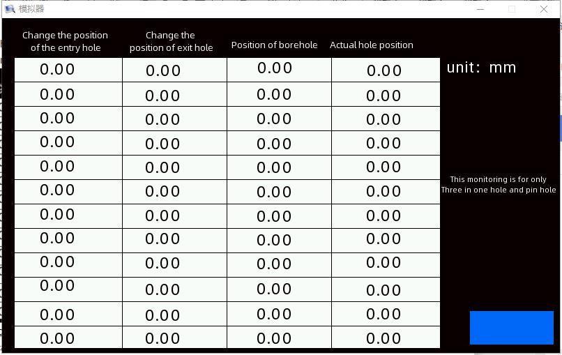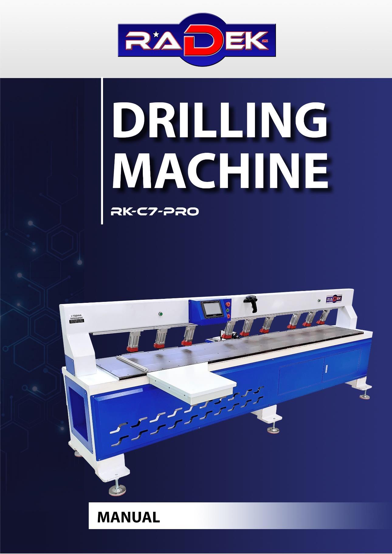
I. Functional characteristics/ functional characteristics
Modern panel furniture generally uses three-in-one hardware for splicing installation. The side hole machine mainly completes the function of side drilling for the plate after the opening of the material opener.
The control system of the side hole machine of our company adopts the way of scanning first and then punching holes, which has the characteristics of high precision and fast speed. It has 11 working modes, such as opening three-in-one hole, left and right wood pin hole, fixed hole, fixed length slot, through slot, both sides blind hole plus center hole, scanning code, foot plate and so on. The control system uses laser ranging sensor to quickly scan the plate, determine the two sides of the plate and the edge of the hole, calculate the hole position or slot position according to the established working mode, and finally carry on the drilling or slotting operation.
The control system of the side hole machine of the company adopts the way of scaThe company side hole machine control system can set the number of mechanical stations, servo axis, tool number. Realize a system compatible with a variety of models.
The control system of side hole machine adopts bus control mechanism, which has the characteristics of high precision, stable work and simple wiring.The error of three-in-one hole is less than 10 wires, and the maximum working speed of walking motor can reach 3000 rpm.
The technical features are as follows:
1. Three holes can be punched randomly.
2. The drilling error is less than 10threads.
3. Walking shaft motor can work at a maximum speed of 3000revolutions per minute.
4. left and right wood pin holes are optional.
5. Two three-pin holes are optional.
6. repeated holes,short spacing hole automatically remove.
7. Automatic filtering of burrs less than 3mm.
8. hole diameter identification,less than or greater than the set value of the hole automatic filtering.
9. Plate edge recognition,fast reversing during plate finding and scanning,and automatic switching of long feed mode.
10. the sequence of three stations drilling,that is,according to the station ready according to the sequence of drilling.
11. The return zero method of positive offset reverse change can solve the change problem of the rotary head behind the zero position sensor. Forward offset reverse zero return mode to solve the problem of zero change behind the zero sensor.
12. User password authorization setting function,convenient for users who need to pay by installments.
13. Blind hole and fixed slot mode.
14. Scan code mode. Parameter comment popover Parameter Notes
二、Electrical wiring instructions
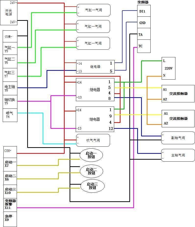
Electrical wiring schematic (for reference only):
1、 Single switch point of
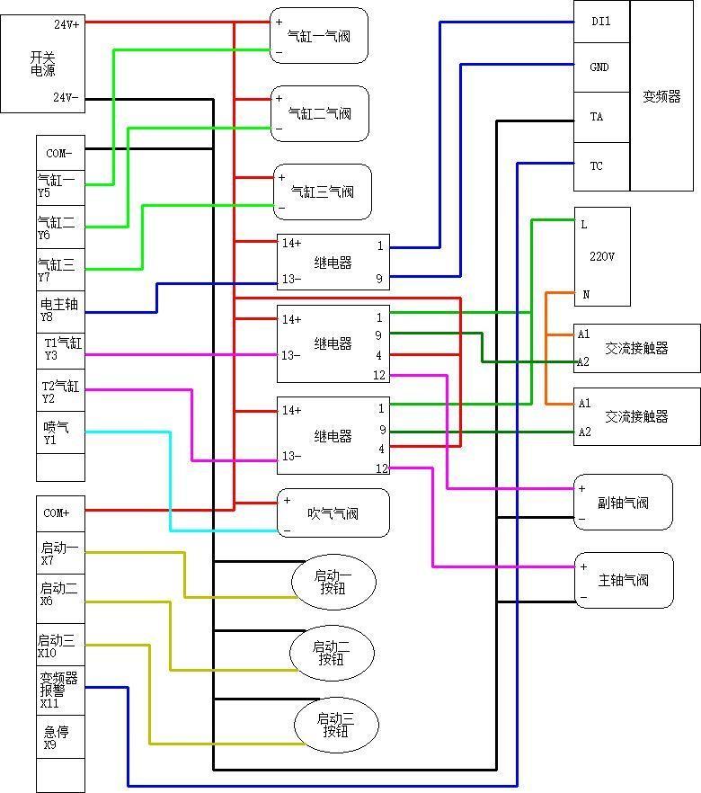
2、 Double switching point
The company's side hole machine control system using drive control integrated machine as the main control unit. Drive control integrated machine as shown below:

Figure 1: Drive control integrated machine
1. controller terminal description
Terminal mark Name of name
L1,L2,L3 Main circuit power input terminal
U 1,V 1,W 1 A shaft servo motor connection terminal
U 2,V 2,W 2 B shaft servo motor connection terminal
PE
Ground terminal
Note
Connect single-phase or three-phase AC (select appropriate voltage specification productmodel). power supply accordingto
Connectwithservomotor.
Connectwithservomotor.
Connect with power grounding terminal groundingterminalforgroundingtreatment. and motor
CN3 Connector RS-485communications.
CN1A,CN1B I/O
CN2A,CN2B
P+, D ,C ,
Connecttheuppercontroller.
Servo motor encoder connector encoderconnectingthemotor.
Use of internal brakeresistance
When using the built-in regenerative resistor, connect theP+and D to open the P+andCends.
Use of external brakeresistance
External regenerative resistor or regenerative unit connecting terminal
Use of external brakeunits
When the capacity of the built-in regenerativeresistorisinsufficient,the P 、 D is placed between the open circuit (remove the short connection) and the externalregenerativeresistorisconnected betweentheP、C.
The P+ and P- of the brake unit are connected to the P+ and end of the servo respectively,andtheP、DandP、 Careinan opencircuitstate.
Wiring of connector CN2A
Connector CN2A input pin signal for controller.


5
9 X01

6 Y07
Output signal 07 16 Y06
Output signal 06 24 BK_B+ +ofBshaft servo lock contact signal
7 Y05 Output signal 05 17 Y04 Output signal 04 25 BK_AA shaft servo lock contact signal -
8 Y03 Output signal 03 18 Y02 Output signal 02 26 BK_A+ +ofAshaft servo lock contact signal
9 Y01 Output signal 01
2.1. System terminal definition tables
Terminal definition Signal definition explain
C OM-
C OM+
External power input negative
A negative common end Y01-Y 12 as the output end
External power input positive A positive common end X 01-X12 as the input end
Input signal incoming signal
X01 Z axis origin Normally on switch by default,valid at low level
X 02 Not used
X 03 X axis origin Normally on switch by default,valid at low level
X 04 Y axis origin Normally on switch by default,valid at low level
X 05 3 start input Station Normally on switch by default,valid at low level
X 06 Station II start-up input Normally on switch by default,valid at low level
X 07
Station 1start-up input Normally on switch by default,valid at low level
X 08 Laser sensor
Default normally closed switch, low level valid
X 09 scram
X 10
X 11
Saw blade alarm
Frequency converter alarm
X 12 Not used
Y 01 Jet whiff
Default normally closed switch, low level valid
Default normally closed switch, low level valid
Default normally closed switch, low level valid
Output signal output signal
Blowing output control.*1
Y 02 T 2 cylinder Control T2 cylinder ejection in double output point mode.*1*3
Y 03 T 1cylinders Control T1cylinder pop-up in point mode.*1*3
Y 04
Y 05
Auxiliary shaft inverter
Double frequency conversion mode control shaft inverter start. *1*2*5
Presser 1 1 pressure cylinder.*1 1
Y 06 Presser 2 2 pressure cylinder.*1 2
Y 07 Presser 3 3 pressure cylinder.*1 3
Y 08 Main Transformer Start In dual frequency converter mode, spindle frequency converter start control. or in singleconverter mode, spindle and sub-axis inverter start signal. *1*2
Y 09 Main Transformer Start In single output point mode, the control signal of spindle and accessory shaft switching is 1/4
Y 10 Saw blade start Saw blade T 4 shaft start signal*1
Y 11 Not used *1
Lock control signal (DP26 core, C N2 terminal)
Lock control signal (DP26 core, CN2 terminal)
1 A shaft lock output negative
10 A shaft lock output positive
2 B shaft lock output negative
11 B shaft lock output positive
3 shaft lock output negative
12 C shaft lock output positive
The third bit P A 510 the servo A shaft needs to be set to 3
The third bit P A 510 the servo B shaft needs to be set to 3
The third bit P A 510 the servo C shaft needs to be set to 3
*1: The output point is a low-level output, i.e. a low-level output when valid and a high-resistance state when invalid.
*2: Inverter startup requires an intermediate relay connection.
*3: Double output point mode means that the ejection cylinder of the spindle and the accessory shaft is controlled separately by two output points (Y2,Y3), which can be retracted at the same time. The dual output point mode can be set in the servo gain parameter screen. *4: Single output point mode means that the ejection cylinder of the spindle and the accessory shaft is controlled by one output point (Y9). In any case, one axis must be ejected and the other axis retracted. Single output point mode and double output point mode can not be used at the same time, can be set in the servo gain parameter screen. *5: Dual frequency converter mode means that the main shaft and the auxiliary shaft are driven by separate frequency converters, respectively. The starting of the spindle and the auxiliary shaft does not affect each other. This mode can be set in the servo gain parameter screen.
2.2Electrical wiring diagram
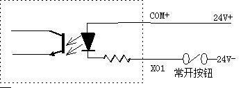

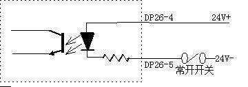
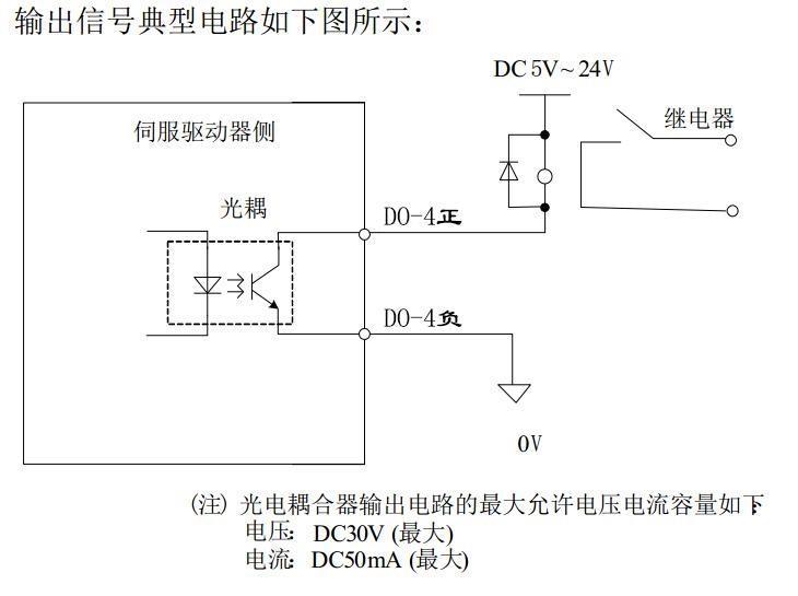
III.Operation screen description
3.1.Do not hit the pin hole mode
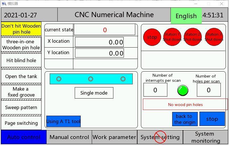
Single board mode: only scan a board at the current station, will return to punch.
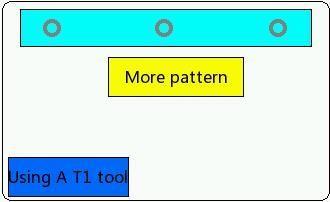
Multi-plate mode: scan all the boards on the worktable from the first starting point of the station to the position of the maximum travel of X axis, and then return to punch. Note: the multi-plate mode is only applicable to the mode without wooden pin holes. If the wooden pin holes are drilled, only the single board mode can be used. Three-in-one hole + wooden pin hole mode
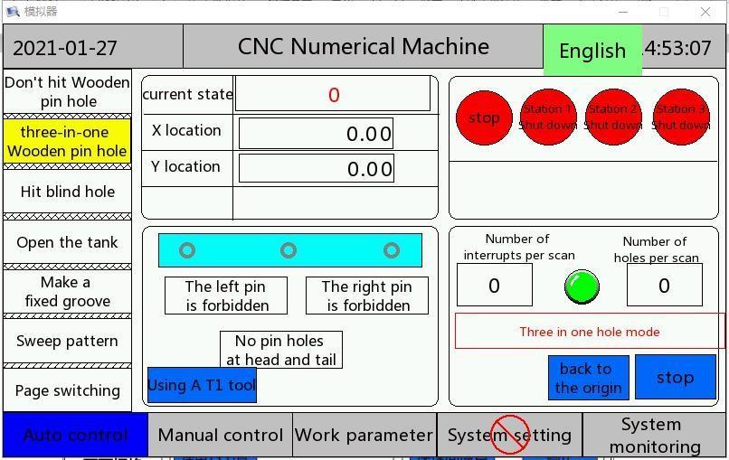
Head and tail no pin hole: in the left and right side of the board only three-in-one hole position, no pin hole.
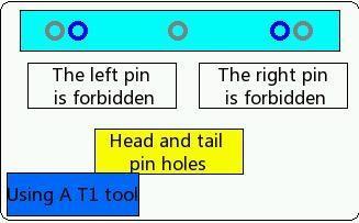
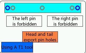
Head and tail export hole: three-in-one hole in the front hole position of the left and right side of the board, and one wood pin hole on the outside of the front face. (as shown in the blue hole above)
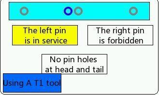
Left wooden pin enabled: when there are three or more positive faces on the board, hit a wooden pin hole on the left side of the three-in-one hole in the middle.(as shown in the blue hole above)
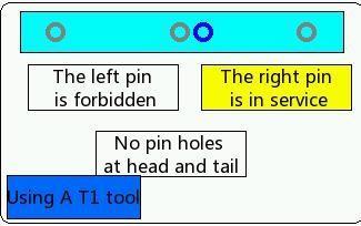
Right wood pin enable: when there are three or more positive faces on the board, hit a wooden pin hole on the right side of the three-in-one hole in the middle.(as shown in the blue hole above)
3.3. Blinding hole pattern
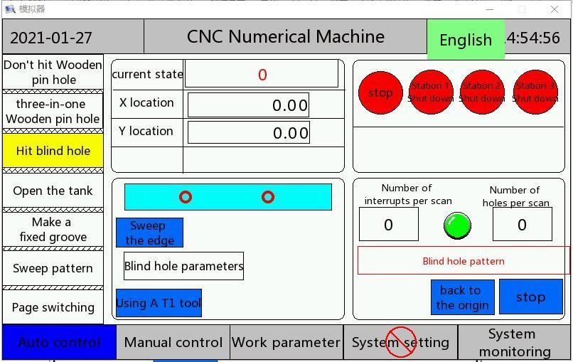
Blind hole parameters

Group number :0~9, a total of 10 groups, each group can set 21 blind holes.
Blind hole depth: the common depth of each group of blind holes.
Edge cleaning compensation: probe scanning board left edge compensation.
Choice: for this set hole can be hit, X for this set hole do not hit
This mode is based on the left side of the board and sets the blind hole according to the serial number.
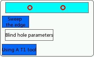
Edge mode: the board is located on the left side of the ruler. The system punches holes according to the position in the blind hole parameters. The edge compensation is on the second page of the system setting, and there is a separate X axis bias compensation for each axis. In the side mode, the three stations work at the same time.
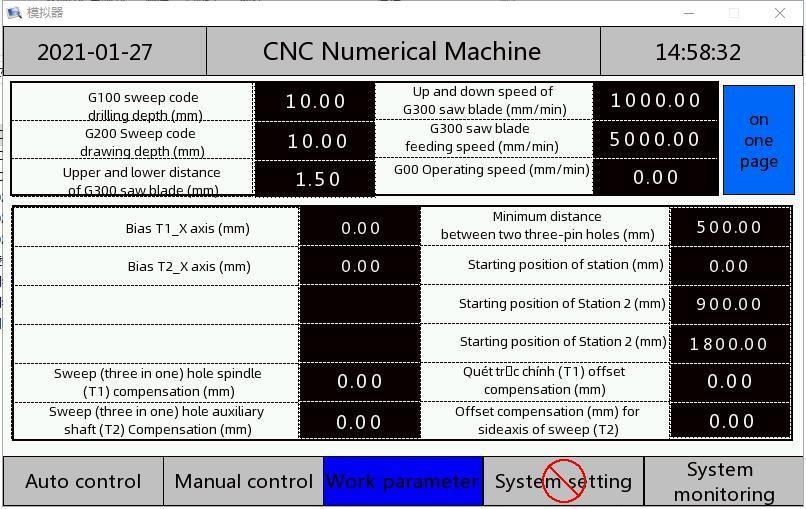
Side one T1_X axis bias: after returning to the origin, T1 the distance between the center point of the tool and the ruler. The value is positive.
Side one T2_X axis bias: after returning to the origin, T2 the distance between the center point of the tool and the ruler. The value is positive.
Side one T3_X axis bias: after returning to the origin, T3 the distance between the center point of the tool and the ruler. The value is positive.
Side one T4_X axis bias: after returning to the origin, T4 the distance between the center point of the tool and the ruler. The value is positive.
3.4. Open slot mode

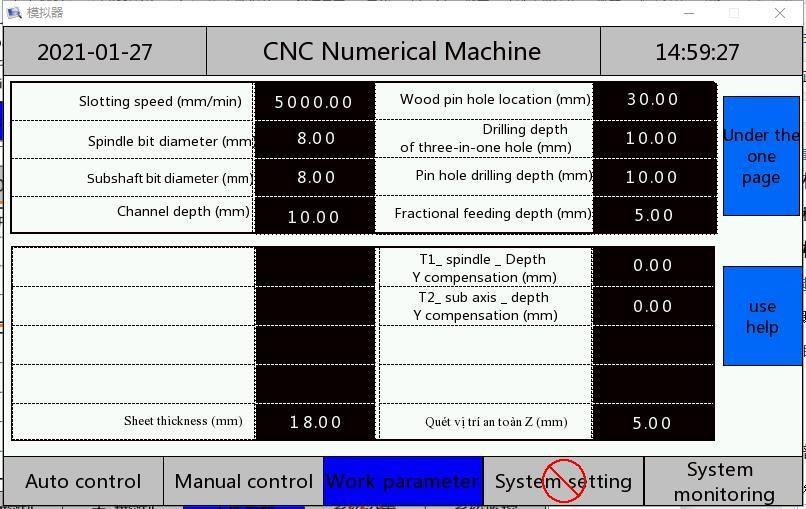
In the working parameter interface, set the parameters needed for slotting.
Slotting speed: the slotted speed shared by all slotted modes.
Split feed depth: the shared feed depth of all slotted modes. This parameter is the maximum feed amount of one feed when slotting, to prevent the depth of one feed from being too large, resulting in a broken knife or knife heating.
Groove depth: the true depth of the opening slot.
Bit diameter: the actual diameter of the bit, used for slotting tool diameter compensation. This mode is used to pull all sides.
3.5. Open slot mode
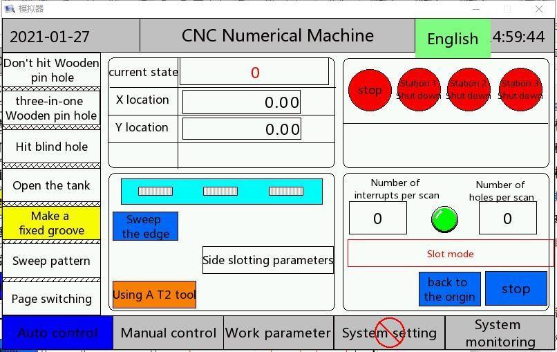
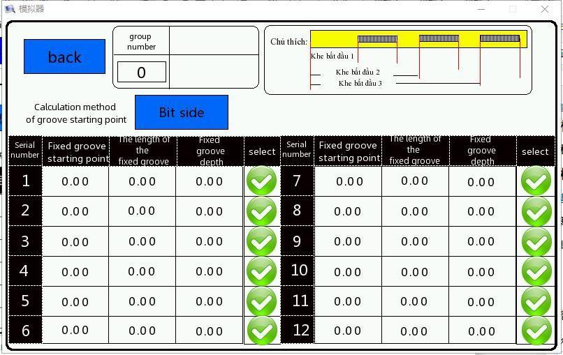
Group number :0~9, a total of 10 groups, each group can set 12 different starting points, different length, different depth slot.
Edge cleaning compensation: probe scanning board left edge compensation.
Starting point: the starting coordinate of the slot.
Fixed slot length: the true length of a fixed slot.
Fixed groove depth: the true depth of the fixed groove.
Selection: the number of this set of fixed slot can be hit, fork number for this set of fixed slot can not be hit.
This mode is based on the left side of the board and opens the slot according to the serial number.
3.6. Blind hole mode on both sides
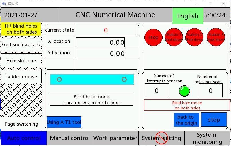

Blind hole left margin on both sides: base on the left side of the board, to hit the position of the left blind hole.
Two sides blind hole left distance compensation: probe scanning board left edge compensation.
Blind hole on both sides of the right distance: based on the right side of the board, to hit the right blind hole position.
Compensation for the right edge of the blind hole on both sides: compensation for the right edge of the probe scanning board.
Left margin on both sides of the blind hole:the position of the left blind hole to be played based on the left side of the board.
Click on the hole mode switch to set a hole in the center of the two blind holes. 3.7.
Scan pattern
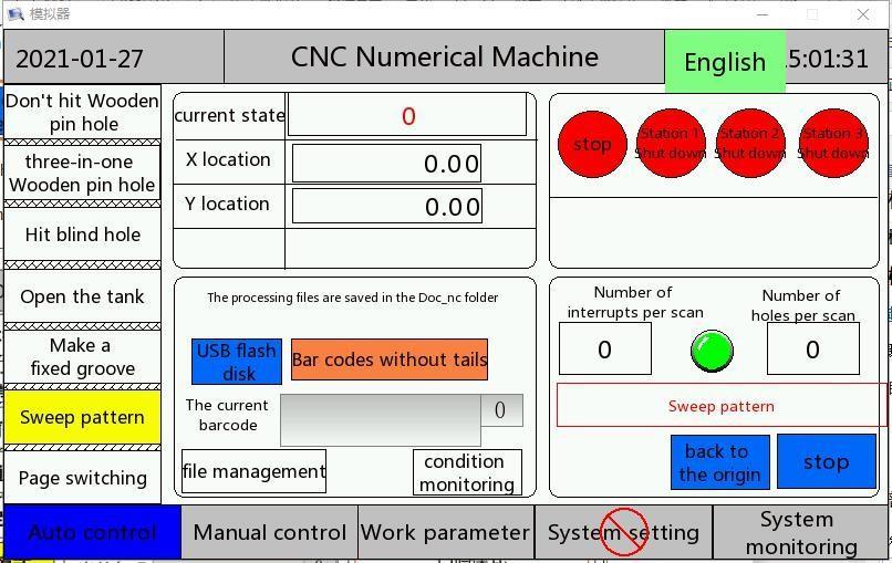
First,create a folder called "Doc_nc" in the root directory of your USB drive,as shown in the figure below
Then put the suffix name. nc G code action file in this folder.Insert the U disk into the USB mouth on the back of the touch screen.
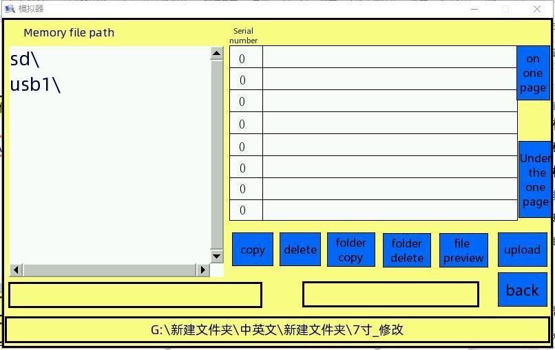
Click the File Management button to enter the file interface, usb1\" path in the red box appears in the memory file path, Enter this path, Find the Doc_nc" folder, Click on the folder copy, U all files in the Doc _nc folder on the disk will be copied into the touch screen memory, Enter the file management screen again to see more Doc _nc folders in memory. Select any in Doc _nc folder in the U disk. nc any file or Doc _nc folder in memory. nc documents. Click "File Preview ", The table shows the currently selected. nc file G code, this feature is used to see if the G code action is edited correctly.Click the folder Delete button to delete the Doc _nc folder in the touch screen memory.


3.7.1, scan code operation


At the automatic control screen, press the U disk button for 2 seconds to switch to memory mode. Press the memory button for 2 seconds to switch to U disk mode. U disk mode indicates that the current selection is in U Doc_nc folder in the disk directory. nc documents. Memory mode indicates that the current selection is in the Doc _nc folder in the touch screen memory. nc documents.
There is already in touch screen memory or U disk. After nc the file, when scanning the bar code of the corresponding content with the scan gun, the status monitoring screen will automatically pop up.(For example, a status monitor automatically pops up when a file named 123456 nc is scanned for a barcode of 123456)

3.7.2, G code description
Criteria G directives supported
Instruction
Meaning
G00 Fast moving
G01
G02
G 03
Linear interpolation
Round arc insertion clockwise
Anti-clockwise arc insertion
G 17 X Y coordinate plane used
G 18 X Z coordinate plane used
G 19
G 90
G 91
Standard characters supported
Character character
Y Z coordinate plane used
Use absolute coordinates
Use of relative coordinates
Meaning
X
Y
Z
X axis identifier, walking axis
Y shaft identifier, bore shaft
Z shaft identifier, lift shaft
R Expression of arc interpolation radius
i Coordinate representation X circular arc interpolation center
j Coordinate representation Y circular arc interpolation center
k Coordinate representation Z circular arc interpolation center
F Command speed
Supporting auxiliary functions M instruction Supported auxiliary function M instruction
M 601-M604
M 50
M 3
M43
Face-to-face instruction
Surface-changing instructions for nondesignated surfaces
T 1,T2 shaft motor starting
Saw blade T4 shaft motor start
M5 main motor stop, T1,T2 shaft motor stop
M 45
M30
Cut-off of saw motor T4 shaft motor
End of procedure
Extended support for G directives of G instructions extended support
G100 Hole, hole back to the previous Y axis position, drilling depth determined by the working parameters of the drilling depth.
G200 A reciprocating slot motion is carried out between the coordinates of the previous instruction and the current instruction coordinates. The pulse slotting depth is determined by the value of the split feed, and the total feed depth is determined by the G200 slotting depth in the working parameters
G300 The saw blade is slotted and the saw blade moves up and down. up and down distance and up and down speed are determined by G300 relevant parameters in the working parameters.
Program Example
M601// first T2//T2 Tools
M3// boot host
G00X56.524Y-10.000Z9.0// move to X56.524,Y-10,Z9.0 position
G00X56.524Y0.300// tool moved to the panel
G17G02R46.971X115.476Y0.300F5000.0// arc interpolation between X56.524 and X115.476
G00X115.476Y-10.000// tool moved to safe position
G00X184.524Y-10.000// tool moves to X184.524 starting point of the next arc groove
G00X184.524Y0.300// tool moved to the panel
G17G02R46.971X243.476Y0.300F5000.0// arc interpolation between X184.524 and X243.476
G00X243.476Y-10.000// tool moves to safety position M5// stop motor
T1// switch to T1 axis
M3// start-up motor
G00X160.0Y-10.000Z9.0// move to X160Y-10.0Z9.0 position
F10000 speed G01X160.0Y33Z9.0F10000// the position of the tool into the Y33 G00X160.0Y10.0Z9.0// tool back to -10.0 safe position M5// stop motor
M603// wait for change
T2//T2 Tools
M3// boot host
G00X100Y-10.000Z9.0// move to X100,Y-10,Z9.0 position
G200X150// slotted using T2 shaft from X100 to X150, slotted depth set by working parameters
M5// stop motor
T 1// switch to T1 axis
M3// start-up motor
G00X160.0Y-10.000Z9.0// move to X160Y-10.0Z9.0 position
G100X160// punch in the X160
G100X200// punch in the X200
M5// stop motor
M30// process closed
3.8. Foot plate and other slot mode
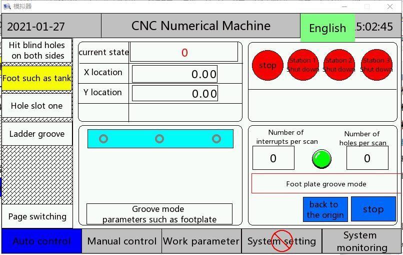
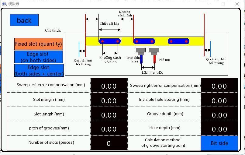
Side slot (both sides): open a slot with the same margin, length and depth on both sides of the board.
Edge slot (center + both sides): in addition to two side slots, a center slot of the same length and depth will be opened between the two slots.
Sweep left compensation: probe scan board left edge compensation. (For footboard, slot mode only)
Sweep the right side compensation: probe scan board right edge compensation. (For footboard, slot mode only)
Slot margin: the spacing between the edge of the slot and the edge of the board.
Slot length: the true length of the slot.
Groove depth: the true depth of the groove.
3.9. Hole slot one

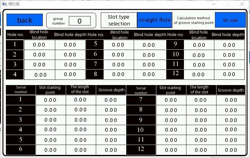
Support drilling in the specified position, slotted in the specified position function.
Slot Type Selection: Straight Slot and Arc Slot
3.10. Manual control
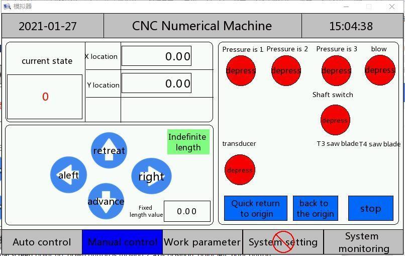
Manual screen point up, down button is moving Z axis position, point left, right button is moving X axis position, point forward, back is moving axis position. The speed of movement is determined by the manual speed of the corresponding axis in the system setting. The system can not be manually controlled in the state of emergency stop, reset and operation.
3.11.f working parameters
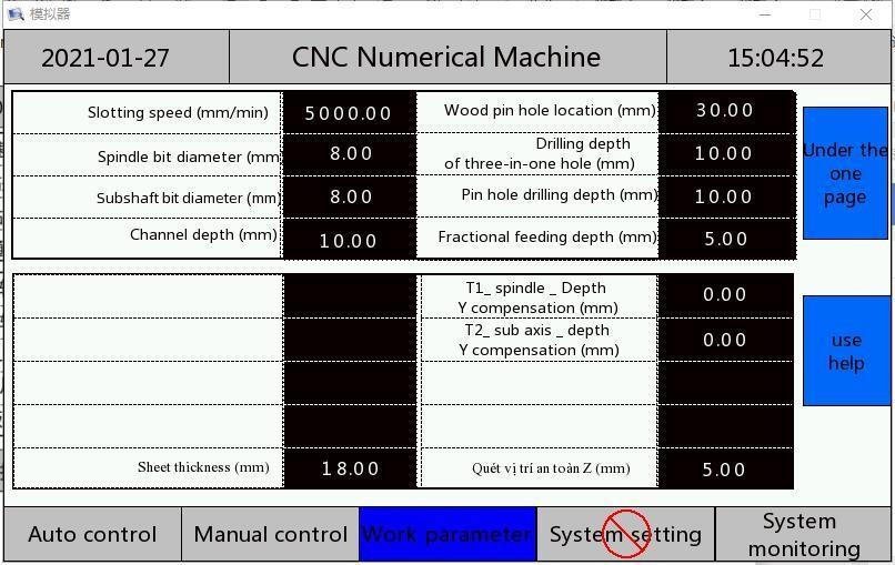
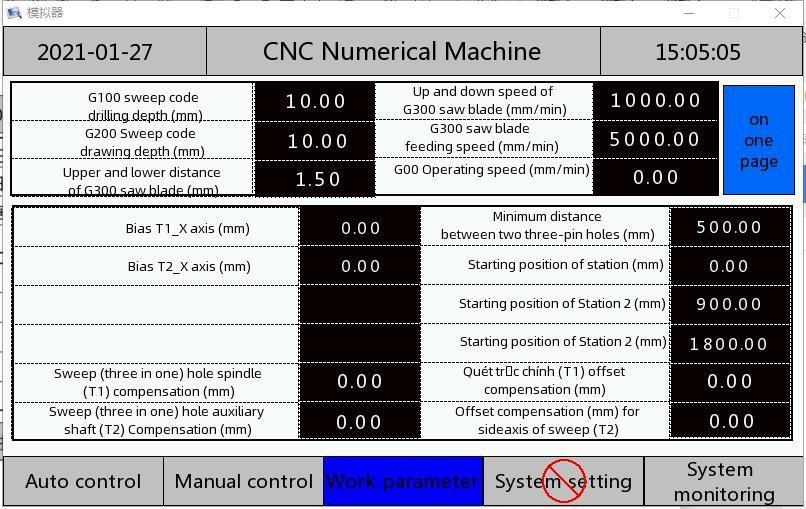
parameter name implication unit
Slot speed Set slot,open slot,G200instruction slot X axis running speed Mm/min
Diameter of spindle bit
Diameter of auxiliary shaft bit
Channel depth
Wood pin hole location
Three-in-one hole drilling depth
Drilling depth of pin hole
Split feed depth
T1 axis _ Z axis compensation
T 2 axis _ Z axis compensation
T3 axis _ Z axis compensation
The actual diameter of the spindle bit is applied to compensate the diameter of the cutter when slotted mm
The actual diameter of the auxiliary shaft bit is used to compensate the diameter of the tool when slotted mm
Slot depth when opening slot mode mm
Spacing between wood pin hole and three-in-one hole mm
The depth of the three-in-one hole in the scanning hole mm
Drilling depth of wood pin hole mm
Slotting operation time several times into the knife, each time into the depth of the knife mm
Distance from origin to platform table when using T1 tool mm
Distance from origin to platform table when using T2 tool mm
Distance from origin to platform table when using T3 tool mm
T4 axis _ Z axis compensation
T1 axis _ Y axis compensation
T2 axis _ Y axis compensation
T3 axis _ Y axis compensation
T4 axis _ Y axis compensation
Sheet thickness
Distance from origin to platform table when using T4 tool mm
Distance of the borehole axis from the origin to the workpiece surface when using the T1 axis tool mm
Distance of the borehole axis from the origin to the workpiece surface when using the T2 axis tool mm
Distance of the borehole axis from the origin to the workpiece surface when using the T3 axis tool mm
Distance of the borehole axis from the origin to the workpiece surface when using the T4 axis tool mm
The actual thickness of the workpiece plate, after the three-axis system reset, the system will reset to the height of 1/2 plate thickness from the table. mm
Scan Y secure location Any axis, the distance between the tip of the knife and the plate of the workpiece during scanning operation. mm
G100 sweep drilling depth When nc file uses G100 instructions, drill depth mm
G200 sweep depth When nc file uses G200 instructions, the depth of the slot mm
G300 saw blade up and down nc file uses G300 saw blade slotting, up and down action distance mm
G300 saw blade up and down nc speed of movement up and down when G300 saw blade is slotted Mm/min
G300 saw blade feed speed When nc file is slotted using G300 saw blade, feed speed Mm/min
Minimum spacing of two three pins
In three-in-one hole and wood pin hole mode, when the distance between the two scanning holes is greater than the set value, a pin hole is automatically inserted. mm
Start position The starting point of station one mm
Position 2 starting position Position of starting point of station 2 mm
Three starting positions The starting point of station 3 mm
3.11.1 Parameter description table:
3.12. System settings
Enter Password Enter System Setup Screen
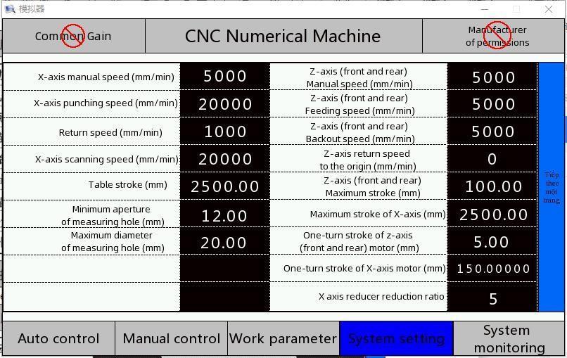
Next page
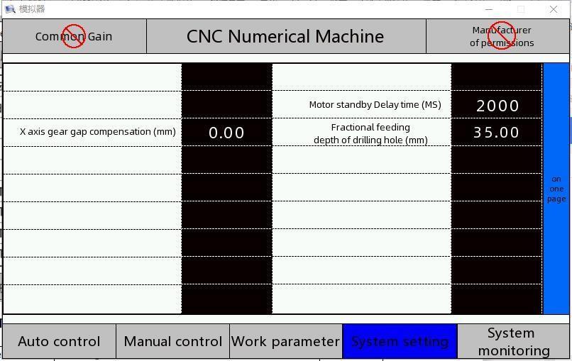
3.12.1. Table of System Settings Parameters
Parameter Name Meaning Unit X axis manual speed X axis movement speed during manual operation Mm/min
X shaft perforation speed
Velocity of movement of X axis during drilling Mm/min
Back to origin Speed of movement of X and Y axes back to origin Mm/min
velocity
X scanning speed X axis movement speed during scanning Mm/min
Worktable Trip Work table total itinerary. *3 mm
Minimum aperture of measuring hole
Maximum aperture of measuring hole
Minimum of effective aperture of scanning hole mm
Maximum effective aperture of scanning hole mm
Z axis maximum travel Trip from origin to safety lowest point mm
Z axis one lap stroke Generally refers to Z shaft lead mm
Y axis manual speed Y shaft speed during manual operation Mm/min
Y shaft feed speed Feed speed when drilling Y shaft. Mm/min
Y shaft retting speed Backoff speed Y shaft drilling Mm/min
Probe sweep hole compensation *5 mm
Y axis maximum travel Y axis soft limit mm
X axis maximum travel X axis soft limit, same as table stroke value 3 mm
Y shaft motor cycle stroke Generally refers to the Y shaft lead. *2 mm
X shaft motor cycle stroke Generally refers to the lead of the X shaft screw, or the circumference of the gear in the rack structure. *1*3 mm
X axle reducer deceleration ratio deceleration ratio of the reducer connected to the X shaft motor. *1*3
Z axis manual speed Speed of Z axis in manual operation, speed of Z axis in origin operation Mm/min
Z axis automatic speed
Adjusted speed of Z axis when switching axis Mm/min
Spindle offset compensation Spindle distance from the laser sensor, used in scanning mode. *4 mm
Main/subaxial bias
Time delay of motor stop
Edge T1X axis offset
Edge T2X axis offset
Edge T3X axis
Distance between spindle and accessory shaft, used in scanning mode mm
When the system stops working, the host starts to stop the delay time. msec
When used in edge mode, T 1 the X axis distance from the tool tip to the ruler. mm
When used in edge mode, T 2 the X axis distance from the tool tip to the ruler. mm
When used in edge mode, T 3 the X axis distance from mm offset the tool tip to the ruler.
Edge T4X axis offset
When used in edge mode, T 4 the X axis distance from the tool tip to the ruler. mm
:: The X shaft deceleration ratio and the X shaft motor cycle stroke setting method, if the X shaft motor connection reducer is 5:1 deceleration ratio, the reducer connection gear shaft circumference is 150 mm, the X shaft deceleration ratio is 5, the X shaft motor cycle stroke is 150
*2, Y shaft motor one-circle stroke setting method, the Y shaft is generally screw direct connection mode, if the screw pitch (lead) is 5, the drilling motor one-circle stroke parameters need to be set to 5.
Be sure to check that the mechanical parameters are set correctly for the first time. ::4. Spindle offset compensation, which refers to the horizontal distance between the laser ranging sensor and the borehole spindle, which is positive or negative for mechanical design reasons.
*5. Probe-scan compensation refers to the fixed bias error in the scanning due to the time difference of the sensor response when the control system performs the scanning hole operation, which is related to the scanning direction, the scanning speed and the sensor response rate. Therefore, the change value at different walking automatic speed needs to be adjusted slightly. When the automatic speed is 70 meters per minute, the value is 0.7, and when the automatic speed is 20 meters per minute, the value is 0.2. 3.13 Servo Gain
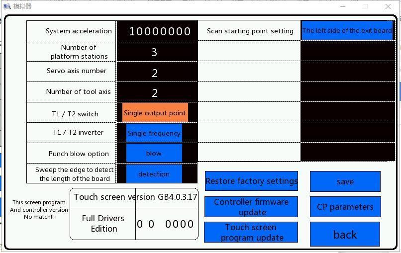
3.13.1 System mechanical parameters table
Parameter Name Meaning Unit
System acceleration when the system is running. mm/min acceleration squared
Platform stations
Number of work stations 2 or 3
Servo Axis Number The system uses several servo motors ,2 or 3
Number of tools The number of tools included in the system, if you use a saw blade, need to be set to 4.
T 1/T2 switching Double output point mode or single output point mode
T1/T2 inverter
Number of inverters used for T1 and T2 axes. Use the same frequency converter, set to single frequency converter mode. Use two frequency converters, set to double frequency converter mode.


