


Contents
preface
Safety rules and precautions
Main parameters of the machine
The installation
Adjustment
Power connection
Lubrication and maintenance
Common faults and troubleshooting
Final assembly drawing and parts list
:Drawing
preface
1.1、This machine is made with reference to the foreign product improvement, consummation, and strict implementation of GB12557-2000 standard.
1.2、This machine is equipped with two sets of gear, with double speed motor, can achieve 8 different feeding speed, to meet different needs. Can be used for planer, edge sealing machine, circular saw, vertical shaft milling and other mechanical automatic feeding.
1.3、Before use, please read this instruction carefully to ensure correct and safe use of the machine. This manual is placed next to the machine for the operator's reference for use and maintenance.
1.4、If you have any questions, please feel free to contact us.
1.5、The machine is constantly being improved and updated. All changes are subject to change without prior notice.
1.6、As a result of compacter level is finite, in the book unavoidably have error omission and inadequacy, beg a user to point out.
Safety rules and precautions
2.1、The host machine used with the machine must meet all safety specifications before use in combination.
2.2、The worktable of this machine should have dust cover to protect the cutting tool, and remove the sundries and tools on the worktable at any time to maintain the safety of the operator.
2.3、Make sure the switch of this machine and host machine is at the position of "stop" or "OFF" before power on.
2.4、The machine is strictly tested before it leaves the factory. It is not allowed to change parts or disassemble the machine at will, so as not to affect the
accuracy of material delivery. When the spare parts are damaged, the reason should be found out and the original spare parts should be replaced.
2.5、Maintain the sharpness of cutting tools and select the right feeding speed to ensure the quality of the work piece. Do not blindly increase the speed of material delivery, in order to avoid the risk of accidents, and cause abnormal mechanical wear.
2.6、If you want to stop the machine, you should stop the machine first, then stop the host machine, and leave after the host machine and the machine stop completely.
2.7、Any adjustment, maintenance, and operation must be performed when the main power switch is turned off and the machine is completely stopped.
2.8、Keep the machine clean at all times and check whether the screws are loose.
2.9、Ensure good working environment, sufficient lighting, proper use of dust collection system, dust cover, etc. (it is recommended to use environment: room temperature + 5 to 40 ℃, 30-95% humidity, voltage, rated voltage ± 5%)
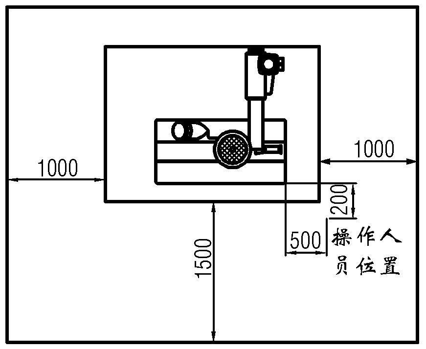
2.10 、 When operating, the operator should wear protective articles (such as eye patch, ear patch, protective clothing, etc.), and should not wear gloves, accessories or loose clothes. Hands and body must keep a certain distance from the machine, do not stand on the path of the workpiece or rebound (as shown on the right: minimum operating space).


2.11、The operator shall not operate during the period affected by alcohol, drugs or drugs.
The main parameters of the machine
3.1 electrical engineering
3.2 Speedometer (inside the plastic cover) 3.3
Feeding speed meter (for reference)


The
installation
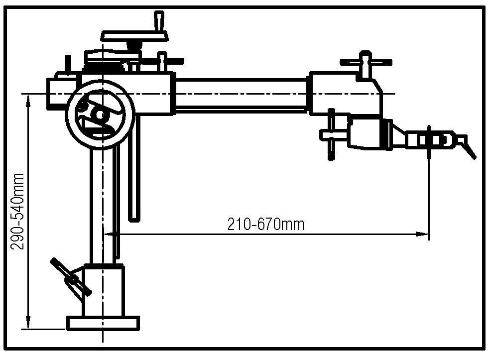
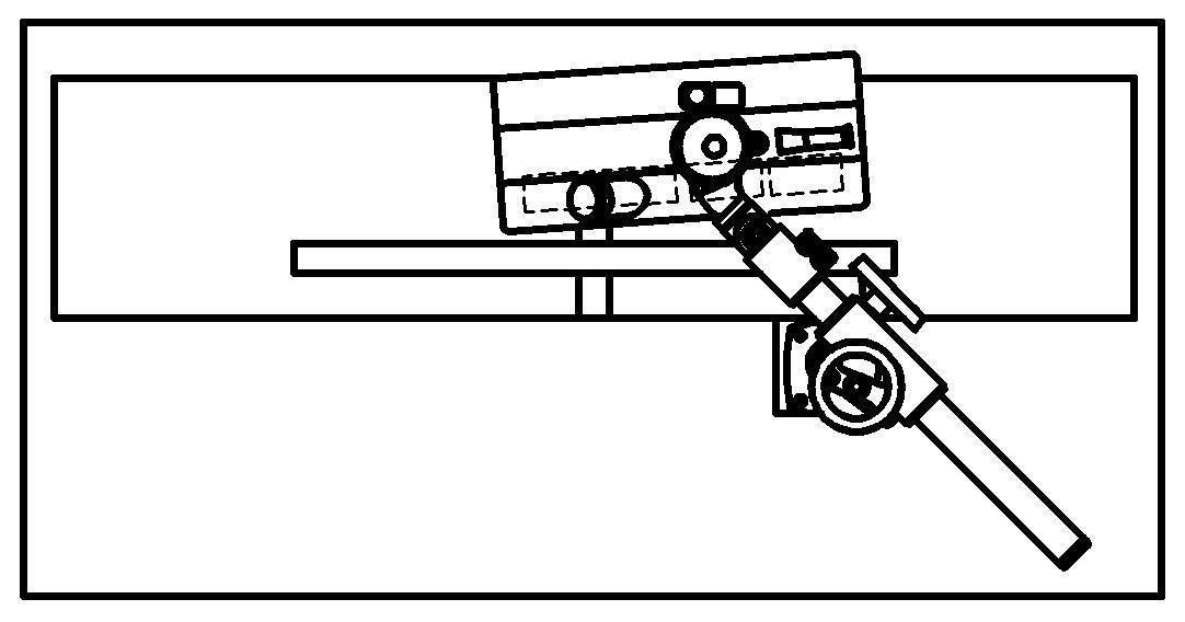
4.1、The horizontal and vertical extension of the tripod (as shown in figure 1).
4.2、
If the mesa of the machine is small, it is recommended to add base extension support (as shown in FIG. 2, which is generally provided by the user himself or purchased by the dealer or the original factory).
4.3 、 Instructionsfor the installation of the material feeder and various machines: (it is recommended to fix the tripod on the "right side of the feed side")


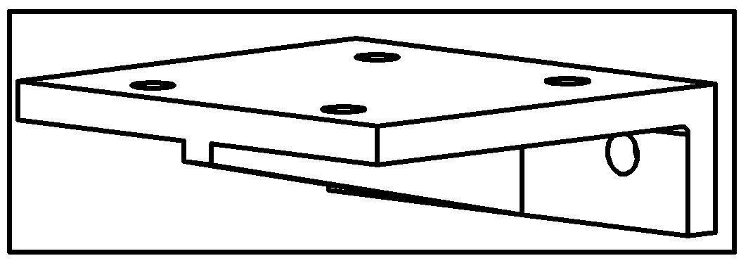
4.3.1、First, drill 4 M12 screw holes on the worktable of the host machine, and drill the specification diagram (figure 3).
4.3.2、 Installation with vertical shaft milling :(direct and profiling)
1 。 The vertical shaft milling guide plate to the appropriate position and fixed.
②The feeding wheel should be set before two wheels of cutting tool, so that the pressure of the wheel directly ACTS on the guide plate, but not on the workpiece between the two guide plates. (see figure 4)

③The height of the wheel shall be increased on the platform first, and the shaft shall be leveled between the shafts first. The height shall be reduced by 5-6mm (see figure 8-1) compared with the thickness of the processed object, so as to give the processed object a certain pressure. The distance between the feed wheel and the guide plate is 3-5mm larger than that between the discharge wheel and the guide plate (see figure 7-1), so that the processed object can move closely to the guide plate.
4.3.3、Installation of circular saw:
①The position of the saw blade should be fixed
Between the third and fourth rounds (see figure 5).
②。 The height of the saw blade should be 5-6mm higher than that of the processed material. Adjust the height of the material feeder to make the material lift the feeding wheel about 4mm when feeding (see figure 8-2).
Figure 5
③In order to ensure the workpiece canbe safely and accurately sent to the baffle, the feeding machine should be roughly aligned with the direction of the baffle (the discharging wheelis5-6mmcloserto thebafflethan the feeding wheel) (see figure 8-1).
4.3.4、:Installation of flat planer:
① All feeding wheels of the feeder must be located on the side of the fixed table top. The feeding wheel should be 5-6mm away from the cutter axis (see figure 6). The pressure should be as low
Figure 6

as possible (see figure 8-2).

7
4.5Assembly (figure 9)
4.5.1、
Figure 9
Fixed base: as mentioned above, after drilling the hole, remove the base (1) from the lifting column group (3), and fix it on the worktable with 4 M12 55 bolts and 4 plain washers.

C= Slight pressing
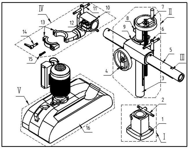
4.5.2 、 Insert expansion tube set into base: loosen no. 2 piece and insert no. 3 piece assembly.
4.5.3、Insert telescopic tube (5) : loosen (6) and (8) piece, take out (5) piece telescopic tube assembly, align one end of the row tooth with (9) piece and slide it in parallel. When the row tooth of the telescopic tube touches the axis of (4) piece, turn the handwheel clockwise to lead it in.
4.5.4、Install the head hanger set: loosen the screw (11) and the fast wrench (12), insert the head hanger set into the extension part of the telescopic pipe, and then tighten the screw and the fast wrench.
4.5.5、
Figure 10
Install the main machine of the material feeder (16) : screw out no. 14 and no. 15 pieces, remove the small half body (13) of the motor rotator, align the neck of the main mechanical and electrical motor of the material feeder and put the large part of the motor rotator (13), then install the small half body (13) back to the original position, and tighten the screws (13 and 14).
Adjustment

5.1、Adjustment of the tripod :(refer to figure 10)
①Rotation of telescopic tube: loosen the adjustable spanner (3) to rotate at any Angle:
② Up and down adjustment of the telescopic pipe: loosen the adjustable wrench (3 and 5) and turn the hand wheel (4);
③ Telescopic tube: loosen the adjustable wrench (3) and turn the hand wheel (2);
Figure 11
5.2 Adjustment of universal joints :(refer to figure 11)
① Adjustment of head hanger (4) : loosen two screws (6)
②Rotation of the main machine of the material feeder on the motor rotator: loosen the fast wrench (7).
③Rotation of rotary joint (2) : loosen the adjustable wrench (5).
④Rotation of the motor rotor (1) : loosen the adjustable wrench (3).


5.3、Position adjustment of the feeding wheel (refer to figure 15) : the end of the feeding wheel must be parallel to the processed object (as shown in the middle of figure 12). If the feeding wheelisinlinewiththeprocessedobject (as shown on both sides of figure 16), the screw can be loosened (6) for adjustment, and the fast wrench can be loosened (3) for adjustment (refer to figure 15).
5.4、Adjustment of pressing force: loosen the adjustable wrench (6) and rotate the handwheel (7).
Note: this machine is the design of the wheels bounce amount to 20 mm, when the thickness of "surface uneven or inconsistent, can also be processed at the same time, but must consider the thinnest processing still has certain pressure, the adjustment, should give full consideration to the thickness of the wood, such as tolerance size, please refer to the figure 8, the cutting amount is larger, can be appropriately increased value, but not more than 15 mm, otherwise it will cause the failure of the host.
5.5、Material tracking: to make the wood under the action of the material wheel, according to the main cutting machine baffle front and then do not run off, can be adjusted (as shown in figure 7).
6.6、Adjustment of material delivery speed:
Note: (1) the material speed and the host tool rotation speed match and the sharpness of the tool is the guarantee of the quality of processing products, wood hardness, cutting volume size is also the factor that determines the material speed.
② Feeding speed: motor speed + gear combination = 8-segment speed (table 3.2)
Loosen the fuselage plum handwheel, remove the plastic housing, you can see the transmission gear set and spare gear set. Remove the screw driver 38 and 39, replace the position of the transmission gear set or load the spare gear set.
Note: the replaced spare gear can be installed back to the matching tooth position and fixed with screws. When installing, please turn the lug on the gear inward, otherwise it will collide with the chain and damage the body. (figure 13)

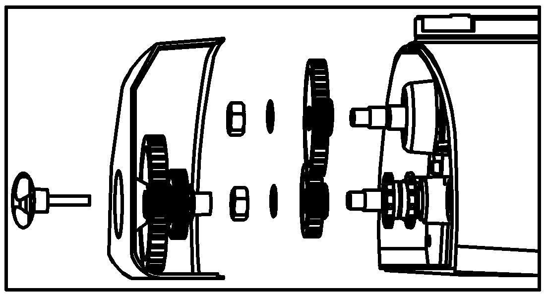
13
Figure 15
5.7 、: Side feeding adjustment duringnormal feeding of main engine:
① Loosen the speed wrench, will send material machine in motor spin counterclockwise on 180 °, let switch box on the right, feeding wheel on the left. (figure 18)
②Loosen the adjustable wrench (figure 11), (7) counterclockwise host 90 °, up, get out of the way to send box feedingwheelnext, and finally tighten adjustable wrench and check each part of the lock. (figure 15)
Note: the direction of feeding wheel is completely opposite to that of normal feeding. When working, please adjustaccording to the arrow on the motorswitch box. See attached drawing: schematic diagram of sign indicating position

Power connection
Note: please connect according to the power specification required by the motor shell and nameplate, the allowable range is 5%. Before connection, please make sure the switch of the material feeder is at (stop) or (OFF) position, which must be operated by registered professional electrician.
6.1 、 The power supply connected to the machine must meet the following conditions:
①Must be equipped with independent circuit breaker, rated current can not exceed 16 amperes.


②The electromagnetic starter must be installed in a place that is convenient for the operator according to the operator's operation habit, so as to stop the machine in case of emergency (press the red button of the starter).
6.2、 Connection of ground wire: the ground wire of the machine is of yellow and green color. After connection, it must meet relevant national electrical standards.
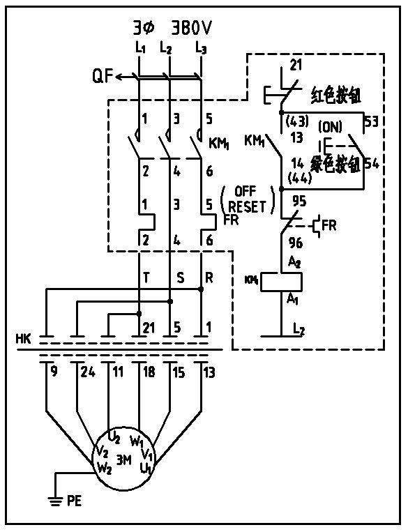
6.3、 Electrical schematic diagram (figure 16) :


Lubrication and maintenance (figure 17)


7.1 、 Open the plastic cover on the left


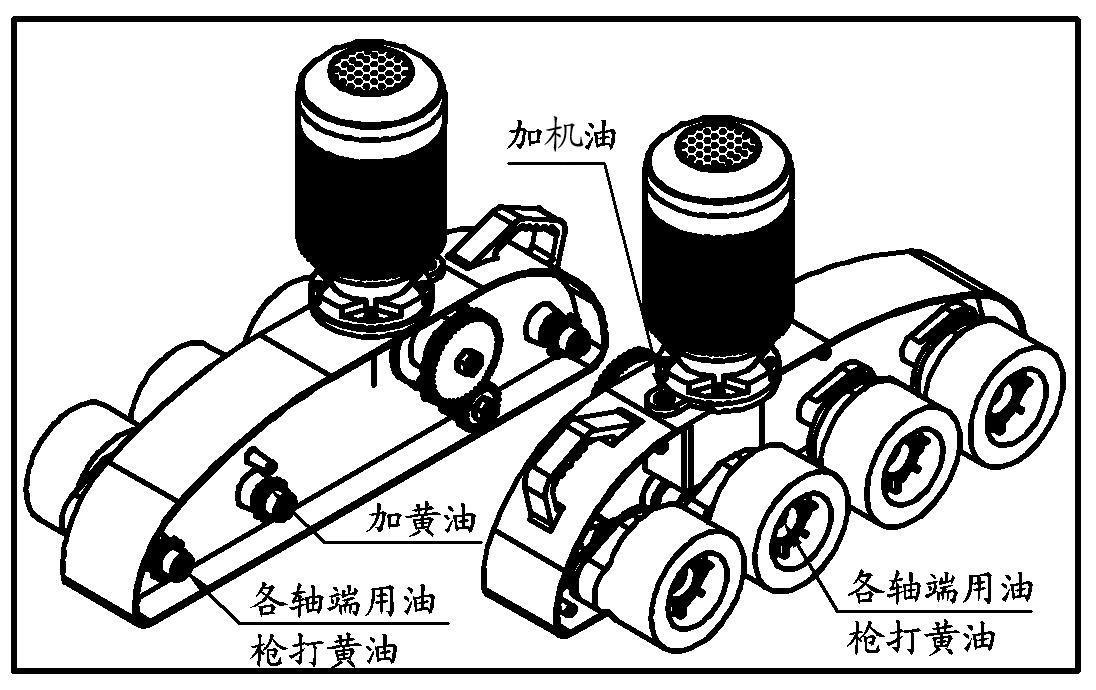


and right of the main engine and you will find 8 straight through pressure filling cups (grease nozzle) and transmission chains. Use the grease gun to fill butter (sodium base grease) at the oil cup every 100 hours or 5 working days.
7.2、Checkthechain,transmissionsprocketandgeareverythree months,and use the air gun to remove dust inside the body, and add butter to lubricate aReplacement of worm gear box oil :(use an open spanner to loosen the oil cover bolt on the housing and pour in the gear oil)
The new machine must be replaced after the running - in period (30 days or 200 hours). After that, change it every 500 hours or 3 months. Standard distance of oil: 38mm from the oil injection hole to the oil level; The recommended oil brand is N150 (anti-oxygen and anti-rust industrial gear oil, SY1172-2000).
Common faults and troubleshooting
Fault phenomenon The cause of the problem Elimination method
The machine is unable to start or has difficulty starting
Insufficient voltage, power supply, phase loss
Connect the voltage in accordance with the motor and check the wiring condition of the power supply line
The machine leaks oil and sounds abnormal
Seal ring is damaged and the gap between sprocket shaft and sleeve is too large
Replace the sealing ring and axle sleeve
Feed is weak and slippery
Poor lubrication of gear, sprocket and chain, abrasion of feed wheel
Add lubricant and replace feeding wheel
Insufficient pressure of feed wheel on workpiece Increase the spring compression
Product processing surface quality problems or feeding is Incorrect arrangement of feeding wheels
Adjust the position of the feeding wheel so that the pressure of the feeding
not smooth wheel on the workpiece ACTS on the guide plate or the worktable surface
Short
life of feeding wheel
When the feeding speed is too fast, the wheels slip on the wood and the cutting tool is not sharp
The wood is not fed on a predetermined trajectory The slant of feeding wheel and baffle is not enough
九、Assembly drawing and parts list
9.1.1、Main engine assembly drawing:
Adjust the feeding speed (refer to 3.3) and replace the sharp cutting tools
Adjust the inclination of feeding wheel and baffle (refer to 6.5)

9.1.2、Host parts list
9.2.1、Bracket assembly drawing
