1. Purpose and characteristics of machine tool 2. Contact
3. Working environment of electrical equipment 4. Vacuum system 5. Residual r isk 6. Operator training
Safety regulations:
Personal safety 9. Machine safety 10 Work area safety 11 Maintain safety
12. Machine parameters
13. Safety module and control system
14. Operation panel
15. Installation of the machine
16. Machine tool operation
17. Lubrication of the machine
18. Tool replacement
19. Cleaning of the machine
20. Inspection of safety devices
21. State of emergency
22. Tensioning the belt
23. Common faults and troubleshooting methods of machine tools
24. Risk analysis
25. Common components table
26. Electrical control principle (with circuit diagram)
27. Random accessories
28. Use of li fting height digital display
29. Counter function mode setting
30. Parameter group
31. Operating procedures
32. Warranty card
Dear Customer:
The machine you purchased may be different from this manual in some details, but as long as you adjust the operation according to the provisions of this manual, it will not affect the safe operation of the machine.
This machine is carefully designed and manufactured by our company with excellent quality. Ensuring the safe operation of the machine and the personal safety of the operating personnel is one of the important principles designed by our company. If it is operated correctly, it can fully guarantee safe production.
Operation of this machine must be performed by trained, responsible personnel with professional knowledge in accordance with regulations. Otherwise, there may be danger. The company is not responsible for losses caused by operational errors.
In order to help you use this machine safely and correctly, please read this manual carefully before installing and using this machine.
1. Purpose and characteristics of machine tool
This machine tool is a new generation of four-side woodworking planer developed by our company based on the market research of our company, based on the opinions of the majority of users, drawing on the advantage s of similar products at home and abroad. The machine is compact in structure and easy to adjust and operate. It is mainly used to process wooden products such as wooden squares, wooden boards, decorative moldings, wooden floors, etc. It is a key equipment for construction forestry, furniture manufacturing and other enterprises.
This machine cannot be used to process light metals (copper, aluminum) and wood-based composites (wood-cement).
2. Contact
Regarding the malfunction of the machine, the customer should describe the following information to us:
1) Machine model
2) Machine factory number
3) Voltage and frequency
4) Purchase date
5) Detailed information about work failures
6) Detailed information about the actions to be performed on the mach ine
7) Working hours per day
We reserve the right to update the machine without any notice.
3. Working environment of electrical equipment
3.1 Ambient air temperature -5 ° C ~ + 40 ° C, the average value of 24h does not exceed 35 ° C.
3.2 Altitude: The altitude of the installation site does not exceed 2000m.
3.3 Atmospheric conditions: the relative humidity of the air at the installation s ite does not exceed 50% at a maximum temperature of + 40 ° C, and a higher relative humidity may be allowed at a lower temperature, such as 90% at + 20 ° C, taking into account Take necessary measures due to condensation on the product due to temperature changes.
3.4 Pollution degree: Level 3.
3.5 Shock and vibration: The product should be installed in a place without si gnificant shaking, shock and vibration.
3.6 The external magnetic field at the installation site should not exceed 5 times the geomagnetic field in any direction.
4. Vacuum system
4.1 The machine should be connected to the dust suction system after installation, 4.2 Do not use the machine in the open air,
4.3 The machine is designed for industrial use, 4.4 Do not use the machine in an explosive environment.
4.5 The air volume of the dust suction system is greater than 5m³/s, and the wind speed is greater than 35-45m/s.
5、△ ! Residual risk
Don’t forget that any machine may be potentially dangerous. Deterministic safety depends on you. The machine will install appropriate protective covers to
ensure the safety of the operator. If they are used and maintained, the protective cover is effective. Even if the safety scheme is maintained and the machine is used in accordance with the regulations, in this operating manual, the following risks may increase:
The machine's cutters are rotating or stalling, Due to the risks caused by the operator in the wrong working position, Because the tool accessories are fixed by mistake, Due to incorrect electrical connection, the direction of rotation of the tool is different, Flashes caused by overheating of parts, It may be in contact with the tool when calibrating the tool, Rotating parts (belts, pulleys, chains, knives, etc.), The powder works without inhalation. Wood processing sawdust rebound may hit the human body.
6. Operator training
The machine operators are trained to use and adjust the machines. The machine operators carefully read this operation manual and pay special attention to safety regulations. especially:
6.1 The machine must cut off the power supply before maintenance, adjustment, and installation of the tool, so that all moving parts can be completely stopped. The work of the electrical system must be carried out by an electrician.
6.2 The operator must abide by the maintenance and safe operation rules of the machine tool.
6.3 It is strictly forbidden to disassemble any parts on the machine w hen the machine is running or when it is not completely stopped.
6.4 Choose the right tool.
6.5 Before starting shipping, you must fully check whether the knife shafts, guide rails, and various adjustment parts are locked, whether the blades are loose, man ually check
whether the knife shafts rotate freely, and confirm that they are correct before starting.
6.6 After starting each shift, please idly rotate the handle of the continuously variable transmission mechanism at high and low speed multiple t imes to prevent rust. It is strictly prohibited to turn the handle when the machine is stopped.
6.7 Before starting the machine every day, check whether all safety devices are reliable. The danger of machine operation should be notified to the operator to effectiv ely prevent the danger, and the safety should be tested regularly.
Important matters
Only the authorized operator can turn on or off the main power switch
7. Safety regulations:
7.1 The operator must read the manual carefully before starting the machine.
7.2 Read the warning signs pasted on the machine carefully.
7.3 Designate the only operator to use the machine.
7.4 Operators must be effectively trained on the risks and precautions for machine use.
7.5 Operators should be trained to periodically check the safety of the machine and the protective cover. If the safety protection device of the machine is faulty, it should be repaired or eliminated immediately. It is strictly prohibited to start the machine with incomplete safety protection device.
7.6 The operator is strictly forbidden to leave the work position when the machine is running and the operation is not completely stopped.
7.7 It is strictly forbidden to touch the parts that are in operation or have not stopped completely.
7.8 This machine has been manufactured to ensure the highest degree of safety and the best performance.
7.9 It is strictly forbidden to stand in front of the wood being fed into the machine.
7.10 The manufacturer is not responsible for compensation for damage caused by modifications implemented on the machine.
7.11 If you are under the influence of alcohol, drugs and medicine, please do not use
the machine.
Safety depends on you, please don't forget that any machine may be dangerous.
8. Personal safety
8.1 Before you start, you have read this manual. Please observe carefully before feeding. Your eyes are the best safety device.
8.2 The operator must wear protective glasses, face shields, hearing protection and other labor protection products, and must not wear too loose clothing, wat ches, jewelry, long hair t ied in the cap, it is recommended to use all nationally designated shoes to avoid accident Personal injury.
Before work begins, you must have the following methods to protect yourself:
a) The leather apron protects itself,
b) Eyeglasses or other appropriate protective eye circles,
c) Masks are a more practical method to resist dust inhalation,
d) take a more appropriate method for ear protection,
e) Gloves are a good way to handle sharp objects,
f) The shoes are reinforced with iron sheet and rubber sole.
9. Machine safety
9.1 Before starting the machine, the lubrication points of the machine must be lubricated.
9.2 The machine tool must have reliable grounding (the grounding terminal sign is in the distribution box).
9.3 Select the width of the feed wheel suitable for the width of the workpiece, adjust the height of the feed wheel and the appropriate pressure.
9.4 The processed wood shall not have hard objects such as nails, gravel, etc., and other objects shall not be placed on the machine work surface and other surfaces.
9.5 Pay attention to the sound and running condition of the motor to prevent the lack of phase operation. If there is an abnormal situation, immediately stop the machine and find an electrician for maintenance.
9.6 When using a saw blade to cut wood, you must install a wood anti-backlash
(backward) device to prevent the wood from flying out and hurting people.
9.7 During the processing, the feed roller must not be adjusted upwards, otherwise the workpiece may rebound and fly out.
9.8 The cutting direction of all cutters is opposite to the direction of wood advancement. Do not change it by yourself, otherwise, the wood may fly out and hurt people
9.9 Pay attention to the balanced state of the cutter shaft. It is stric t ly forbidden to install unbalanced cutters on the cutter shaft and they are well clamped.
9.10 Be very careful about any movements during work, and regularly check the protective cover and safety equipment. All protective covers have been f ixed and e ffective, otherwise, start- up work is not allowed.
9.11 Make sure there are no debris (tools, spare parts, etc.) on the work surface before starting.
9.12 Install the correct working direction when the tool is installed.
9.13 When installing a tool, the tool and parts related to tool clamping must be clean.
9.14 Do not use deformed tools, and pay attention not to exceed the speed l imit specified by the tool manufacturer.
9.15 All dust suction ports must be connected to the dust collection system. Make sur e that the dust collection system is turned on before starting work.
9.16 Adjusting the inspection machine with tools may be possible without a protective cover.
9.17 When the machine is running, do not try to remove waste or parts from the work area.
9.18 After the machine rotates for a certain period, the belt will be slack, you need to stop the machine and tighten the belt.
9.19 Remove wood chips regularly to prevent fire hazards.
9.20 The machine is firmly fixed on the ground.
9.21 Relevant safety signs and operation tips posted on the machine should be cleaned
and protected, and updated when they are blurred.
9.22 Do not process wood that is too large or too small.
10 Work area safety
10.1 Keep the work site clean and hygienic, and the stacked items shall not affect the sight of the operator and shall not occupy the passage.
10.2 The components of the machine should be cleaned of dust after every shift, and the dust in the electric box should be removed once a week (by an electrician).
10.3 The work area should have good lighting and sufficient space, so that the operator is always located outside the hazardous area.
10.4 A good ground level prevents the risk of waste and debris sliding down.
10.5 Only authorized operators can stay in the work area.
10.6 The operator must not stay on the rail where wood chips and tools rebound and spray. If this rail is another work area (another machine) or another passage, a barrier that gives full protection should be installed immediately.
11 Maintain safety
Don' t think that the electricity has been cut off during maintenance, check it yourself!
11.1 Any adjustment or disassembly of the machine must turn the main switch to the OFF position and indicate it with a sign.
11.2 There is a concealed buckle at A, which can be pulled out and locked with a lock. The key is kept by the designated operator. This method can be used for cleaning and maintenance to prevent other personnel from operating the main switch to bring danger.
11.3 Before cleaning the machine and removing any protective
cover for maintenance, the machine must be completely stopped.
11.4 The cleaning and maintenance operations of the machine (especially the work surface) and the surrounding ground are an important safety factor.
11.5 Use proper gloves when loading and unloading tools.
11.6 The tool requires regular maintenance. Replace it with spare parts.
11.7 Any failure of the machine, protective cover and cutter must be taken immediately measures.
11.8 Perform regular cleaning and maintenance work to remove wood chips and dust to avoid fire hazard.
12. Machine parameters
Working width
25-210mm
Working thickness 8-120mm
Feeding speed 10-45m/min
Main shaft diameter 1800mm
Spindle diameter φ40mm
Axial movement 0-20mm
Main shaft revolution 6800r/min
Pneumatc source Pressure 0.6Mpa
1st Bottom Spindle 5.5kw Right side spindle 5.5kw Left side spindle
First top spindle
Feeding beam rise&fall
General power
29.1kw
Trimming 145-160mm
First bottom spindle 125-140mm
Right side spindle 125-165mm
Left side spindle 125-165mm
First top spindle 125-165mm
Dust outlet diameter 140mm
Feeding Wheel diameter 140mm
Dimension 4100x1630x1750mm
Figure 1C-1
2. Power indicator
3. Emergency stop button
4. Operation panel switch lock
5. Emergency stop indicator
6. Start and stop the left vertical axis (green start red stop)
7. Start and stop of rear axle
8. Start and stop of the front upper shaft
9. Feeding jog forward
10. Feeding jog backward
11. Continuous feeding button
12. Continuous feeding stop button
13. Lighting switch
14. Right vertical axis start and stop 15. Front lower axis start and stop
18-1 Lifting and unloading of the machine
Remove all transportation and packaging parts before unloading. When the machine is lifted by a crane or a forklift, when the machine tool is hoisted, wire rope should be hung on the hooks at both ends of the top of the machine tool cover (Figure A, Figure B), and set on the crane hook to lift. Balance to prevent the machine from tipping over. If the eye bolt is installed above the hook, please note that the eye bolt is only used to fix the machine during transportation and cannot be used for lifting. If this screw is used for lifting, the machine manufacturer is not responsible for the consequences.
Figure A Figure B
△ !
Make sure that the crane, sling, and forklift lift the machine properly and safely. Avoid sudden transportation during the lifting of the machine. It is strictly forbidden to stand under the machine after lifting and during transportation.
18-2 Installation and horizontal adjustment
a) Before unpacking the machine, the installation location should be determined. The installation location should have good lighting and sufficient space (at least 500 LUX), with a suitable power cord and dust suction system.
b) The machine tool should be placed on a solid concrete floor. The thickness of concrete is not less than 150mm. Place a 10mm thick steel plate 3 under the screw hole of the bed foot, adjust the bolt 1 to keep the level of the machine tool within 0.2 / 1000mm, and finally tighten the nut
18-3 Electrical connection and grounding
Electrical connection and testing should be performed by a skilled electrician to determine that the company's power system can meet the power requirements of the machine. Check that the voltage of the power transmission line is consistent with the
machine. Check the direction of the saw axis after turning on the power. Because the machine is equipped with a phase sequence relay, if the wiring phase sequence does not meet the requirements of the machine, the motor shaft will not be started. At this time, the power should be turned off and the position of the two-phase line should be replaced. After the machine can start normally, che ck the direction of tool rotation.
18-4 Connection of vacuum system
△ !
For the safety of the operator, the machine must be connected to the vacuum system.
When working, the vacuum system is always open, and connect the exhaust pipe to the vacuum system with a hose of appropriate diameter (if they are plastic hoses, they must be made of non-flammable materials),
Exhaust pipe diameter: φ140mm
The normal operation of the vacuuming system will properly absorb the dust to ensure work safety and reduce risks.
Other factors to reduce the amount of dust in the working environment:
-Maintenance of tools, machines and vacuum systems
-Appropriate cutting speed and feeding speed
-Exhaust pipe proper adjustment, protective cover
-Proper use of protective devices against dust.
19. Machine operation (figure 1)
19.1.1 Height (up and down) adjustment (see Figure 1)
First release the locking handle 16, and then use the special wrench to turn 1, the front lower knife shaft will move up and down. Place a knife adjustment ruler on the workbench behind the tool (see Figure 2), let the blade touch the knife adjustment ruler, and then rotate the knife shaft by hand. When you feel a slight friction contact, the adjustment is good. Then lock the handle 1. Note: In order to eliminate thread clearance, the height of each cutter shaft must be raised from the bottom to the bottom, and locked when in place. When adjusting downwards, first reduce the excess and then increase to the required height.
19.1.2 Axial (front and rear) adjustment (see Figure 2)(figure 2)
Loosen the locking bolt 2 first, turn the screw 3, and the cutter shaft moves laterally. After adjustment, tighten the bolt 2 and lean on the small support plate 1 with the adjustment ruler. When the knife 5 and the adjusting blade feel a slight friction contact, the trimming knife is flush with the small backing plate, and the adjustment
is good. When the machine tool does not have a small backboard, it is not necessary to decorate the edge knife.
(figure 3)
Turn the handle 3 and move the front table 2 to move up and down to form the first lower planer knife eating amount, and then adjust the handle and tighten the handle. 19.2.2 Front leaning plate adjustment
When the handle 4 is turned and moved, the front guide plate 1 moves back and forth to form the amount of the right vertical planer. After adjustment, tighten the handle 3again. According to the bending degree of the wood, adjust the distance between the front leaning plate and the small leaning plate 4 (see Figu re 4), and the distance between the small leaning plate and the guide plate 3 behind the right vertical knife is 0.5 (generally adjusted at the factory). When there is no small leaning board, directly adjust the offset distance between the front leaning board and the rear leaning board 3
to be the amount of knife eaters. The panel 2 can be moved to accommodate cutters of different diameters.
(figure 4)
19.3 Right vertical knife shaft adjustment (see Figure 5)
(Figure 5)
19.3.1 Axial (front and rear) adjustment
Use the adjusting knife against the rear guide to bring the blade into contact with the adjusting knife (see Figure 5). Then turn the knife shaft by hand. When you feel a slight friction contact, the position is adjusted. Loosen the locking handle 3 (see Fig. 1) and turn the adjusting lever 14 , the r ight vertical knife shaft can be moved axially, and then the handle 3 is locked after adjustment.
19.3.2 Height (up and down) adjustment (see Figure 1)
Loosen the locking handle 15 and turn the adjusting lever 2 to move the knife shaft up and down. After adjusting, lock the handle 5 again.
19.4 Left vertical knife shaft adjustment (see Figure 1)
19.4.1 Axial (front and rear) adjustment
Loosen the locking handle 12 and turn the adjusting rod 4, the left vertical shaft can be moved axially. Lock the handle 12 after adjustment.
19.4.2 Height (up and down) adjustment
Loosen the locking handle 13 and turn the adjusting lever 5, the knife shaft will move up and down, and then lock the handle 13 after adjustment. (Figure 6)
3 2
1
19.4.3 Adjustment of the pressing devices on both sides of the left vertical knife shaft (see Figure 6)
The baffle 1 located behind the tool is leveled with the blade edge with a knife adjustment ruler. The position of the pressure plate 2 and the two pressure wheels 3at the front of the tool should be 3mm less than the distance from the blade to the plate. The baffle 1 and the pressing plate 2 are as close to the cutter as possible to improve the processing quality. After the upper and lower clamping devices of the knife shaft are adjusted, adjust the knife shaft laterally to the required processing width.
19.5 Upper knife shaft adjustment
19.5.1 Height (up and down) adjustment (see Figure 7)
Loosen the locking handle 6 and turn the adjusting lever 7 to move the knife shaft up and down. After adjusting, lock the handle 6 again.
Note: In order to eliminate thread clearance, the height of each cutter shaft must be raised from the bottom to the bottom, and locked when in place. When adjusting downwards, first reduce the excess and then increase to the required height.
In Fig. 7, 1 is the feed forward switch, 2 is the feed backward switch, and 3 is the tight stop switch. Installed at the rear of the machine shield for easy operation and adjustment.
(Figure 7
19.5.2 Axial (front and rear) adjustment
(See Figure 9) Loosen the locking bolt 8, there is one such locking bolt on the front and rear upper shafts, turn (Figure 8) the adjusting rod 3, the knife shaft can be moved axially.
19.5.3 Adjustment of front and rear pressure plate devices
(See Figure 8) Front pressure plate: Loosen bolt 7, turn handle 5, adjust the lowermost end of front pressure plate 8 to be about 3mm lower than the blade, and turn screw 6 to adjust the pressure of the front pressure plate spring. Rear pressure plate: Turn the handle 4 to move the rear pressure plate up and down. After adjusting, the bottom ofthe pressure plate 1 is about 1mm higher than the knife ruler. The front and rear pressure plates 1 and 8 can be adjusted according to the diameter of the cutter 2 to move the cutter closer or away. Try to keep the pressure plate close to the cutter.
(Figure 8)
19.6 Rear lower knife shaft adjustment
19.6.1 Height (up and down)
(Figure 9)
Loosen the locking handle 10 (see Figure 1) and turn the adjusting lever 8, the knife shaft can move up and down. Adjust the blade with the blade to be flush with the back platen. When leaving the factory, the back surface is about 0.2mm higher than the front surface.
19.6.2 Axial (front and rear) adjustment (see Figure 11)
Loosen the locking bolt 1, turn the screw rod 2, the cutter shaft can move axially, and then tighten the bolt 1 after adjustment.
(Figure 11)
19.7 Table roller adjustment (see Figure 12)
(Figure 12)
Two sets of active rollers are installed in front of and behind the machine table, and the adjustment is performed on the back of the bed. The nut 1 is used to adjust the height of the roller, and the screw 2 is used to adjust the rear locking. Generally, the front roller (tooth roller) is 2 to 3 mm higher than the table, and the rear roller (gloss roller) is 0.05 to 0.1 mm higher than the table.
19.8 Feeding system adjustment
19.8.1
Feed roller adjustment
The feed roller 1 can be moved on the shaft, generally it should be pressed against the middle of the workpiece (see Figure 13) to improve the processing quality. The lifting and feeding roller is raised and lowered accordingly to adapt to the work of different thickness. Each feeding roller can be adjusted up and down independently. Loosen the lower nut of the cylinder rod and turn the cylinder rod.
(Figure 13)
19.8.2 Pressure regulation of feeding system
The black knob on the air source triplet 9 located at the right end of the feed beam of the machine tool (see Figure 14). Pull up and turn the knob to adjust the pressure of the first and second groups of cylinders in the feeding syste m. The general air pressure is not less than 0.4MPa , Pay attention to regularly inject oil into the oil cup, and regularly drain the water in the water cup. In Fig. 15, 1 is a pneumatic pressure regulating valve, which adjusts the feeding wheels of groups 3,4, and 5. The pressure gauge above 1 shows its pressure. In Fig. 15, 2 is a pneumatic pressure regulating valve, which adjusts the feeding wheels of groups 5 and 6. The pressure gauge above 2 shows its pressure.
19.8.3 Adjustment of feeding speed
Rotate the handle 3 in Figure 15 to adjust the speed of the feed roller. When the amount of knives is large, the wood is hard, or the surface of the processed parts is required to be clean, the lower feeding speed should be selected; otherwise, th e higher feeding speed should be selected.
19.8.4 The pneumatic switch in Fig. 15 can control the first two groups of feeding wheels to go up or down
(Figure 14) (Figure 15)
20 Lubrication of the machine
20.1 A manual lubrication pump is installed at the lower left of the machine, as shown in Figure 16, the manual pump oil can lubricate two working surfaces.
20.2 Each main shaft bead is equipped with a grease nipple, which can be lubricated with a grease gun to lubricate each knife shaft bead and feed wheel bead.
(Figure 16) (Figure 17)
20.3 Lubrication and maintenance of machine tools
Regular lubrication of the refueling point should be implemented according to Table 2.Always keep the appearance of the machine tool clean and the guide rails of the moving parts clean.
Lubricated parts
Recommended lubricants Lubrication cycle
Outer diameter of each spindle Oil N46
Horizontal shaft lifting screw and nut Oil N46
Horizontal shaft lifting rail Oil N46
Vertical shaft lifting screw and nut
Vertical shaft lifting thrust bearing
Oil N46
Calcium base grease ZG-3
Screw nut of vertical shaft forward and backward Oil N46
Vertical shaft guide Oil N46
Vertical shaft thrust bearing Calcium base grease ZG-3
Front guide plate connecting rod shaft Oil N46
Feeding lifting column Oil N46
Feeding lifting worm gear box
Industrial gear oil N460
Once in three shifts
Once in three shifts
Once in three shifts
Once a week
Once every six months
Once a week
Once in three shifts
Once in three mouth
Once in three shifts
Once in three shifts
Once a year
Feed reducer Industrial gear oil N460
Feed roller pin Oil N46
Left vertical knife front pressure plate pin Oil N46
Front horizontal platen pin
Rear horizontal plate guide rail
21. Tool replacement
N46
N46
Once every 4000 hours
Twice a shift
Once a shift
Once a shift
Once a shift
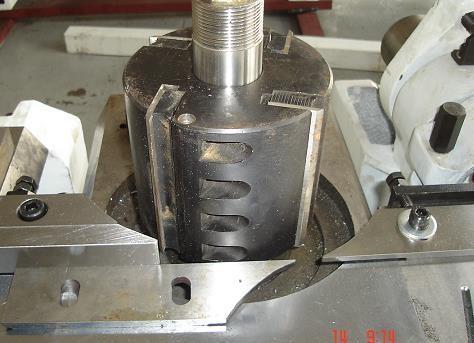
21.1 Each cutter shaft is equipped with a shield as shown in Figures 19 and 20, which has a danger sign and the direction of rotation of the cutter. Install the tool in the direction shown on the shield. When installing the tool, both hands should wear appropriate gloves to prevent the hand from being scratched by the tool.
21.2 Before replacing the tool, press the emergency stop button, the machine must be completely stopped before opening the cover door, and lock the control circuit with the 5operation panel switch in Figure 1C-1. The key should be kept by the operator. Turn the main power switch to the OFF position.
21.3 Check whether the cutter is sharp and remove all dust from the cutter. The machine is equipped with many washers. All dust should also be removed before the gasket is assembled.
21.4 Use special tools provided with this machine to load and unload knives. (Figure 19) (Figure 20)
22. Cleaning of the machine
Daily machine cleaning can extend the life of the machine and is an important safety factor. Here are some regulations. Weperform proper vacuuming and cleaning every night:
1) Countertops, backboards and all cavities (as shown in Figures 21 and 22, worktops, backboards, etc.)
2) Clean all movable parts and components exposed to dust ever y week. (Figure 21) (Figure 22)
23. Inspection of safety devices
-The safety device of the machine should be effective at all times. Check the emergency stop button every 2 weeks: when the machine presses any emergency stop button under normal operation, all driving devices can be stopped immediately.
-Check the validity of each travel switch every 2 weeks and the validity of each button switch.
-Check regularly whether each protective device is effective.
-The technician in charge of the inspection shall inform which areas have been inspected and the results of the inspection.
24. State of emergency
If the room where the machine is installed is flooded, the power should be cut off immediately. Before starting work again, the machine must be tested by a skilled technician.
If there is a fire, immediately turn off the power and use a fire extinguisher to spray the flame. Before starting work again, the machine must be tested by a skilled technician.
To be precise, the safety regulations are unobstructed in the working area around the machine, so that even if a hazard occurs, the operator can leave safely. The machine cannot be used in explosive rooms.
25 Belt tensioning
After the machine is used for one cycle or many working hours, the belt will be slack. At this time the belt will need to be tensioned, which will increase the time the machine stops. The best tension is to apply a 3kg force in the middle of the belt, and you get a bend of about 5mm.
The tensioning is proceeded as follows:
1) Stop the machine, turn the main power switch to the OFF position, and lock it with a lock. The key is kept by the operator and hangs the information being maintained here.
2) Remove the rear door.
3) The upper shaft and the lower shaft directly loosen the bolts that fix the motor, and use the weight of the motor to tension the belt and tighten the bolts.
4) The left and right vertical shafts are shown in Figure 3. Loosen the nut 1, t ighten the belt after tightening the bolt with a 17-19 rigid hand and tighten the nut.
5) Re-fix the back door.
(Figure 23)
26. Common machine tool failures and troubleshooting methods
Fault phenomenon Causes or troubleshooting
a. Check the circuit and motor;
1. Cannot feed or the feed wheel stops halfway when feeding, or is not smooth
2. The entire feeding mechanism does
b. Check whether the transmission opening and closing pulley is working properly;
c. Check whether the flat key of the feed reducer falls off;
d. Check whether the universal joint is bent or broken;
e. Check whether the feeding roller pressure and material density are correct.
a. Check whether the lifting limit switches SQ2, SQ3, SQ4 (down), SQ1 (up) are connected, and the motor is missing phase.
not go up and down
3. Noisy
4. The motor can not start, there is a strange noise when starting
5. The indicator light of the power supply is off, and the motors will not start after pressing each start button
27. Risk analysis
b. Check whether the flat key of the elevator speed reducer falls off;
c. Check whether the lifting nut is worn.
d. The feed beam touches the upper knife shaft seat limit switch and lowers the upper knife shaft a little.
a. Check if the bearing is damaged
b. Check whether the knife is installed correctly
a. Motor overload, (eliminate the cause of overload)
b. Motor running without phase
c. Relay failure (check the relay)
a. Check if the main circuit is missing
b. Check whether the control fuse FU is blown and whether the output voltage of the control transformer is 220V.
c. Check whether the emergency stop buttons SB11 and SB12 are in the closed position, and whether the overload indicator HL11 is illuminated.
of the tool caused by cutter rotation above the first tool, and the machine also has a fully enclosed outer cover (see Figure 24 and outline drawing)
2. These safety devices must be kept forever.
Working position
The wood chips produced by the cutter processing wood fly out and cause harm to the human body Serious Low 1. Fully enclosed outer cover, and warning signs are affixed at the feed inlet,
2. The operator should not stand on the track where wood chips fly out when the wood is being aligned with the cutter
Replacing knives
The damage of the sharp blade to the human body Serious Low
Wear work clothes, shoes and suitable gloves when changing tools
(Figure 24) (Figure 25)
28. Common components table
Table 3 List of rolling bearings
Name Model Model and installation location
Deep groove ball bearings SKF 6009-2Z/P5 Front end of upper horizontal axis
Deep groove ball bearings SKF 6306-2Z/P5 Rear end of upper horizontal axis
Deep groove ball bearings SKF 6009-2Z/P5 Front end of lower horizontal axis
Deep groove ball bearings SKF 6306-2Z/P5 Lower end of horizontal axis
Deep groove ball bearings SKF
6009-2Z/P5 Vertical shaft
Deep groove ball bearings SKF 6306-2Z/P5 Vertical shaft lower end
Deep groove ball bearing
Deep groove ball bearing
Deep groove ball bearing
6006-2RS Front end of feed roller
6005-2RS Feed roller rear end
6006-2RS Feed roller under table
Thrust ball bearings 51102 Horizontal axis lift
Thrust ball bearings 51104 Vertical shaft lifting
Thrust ball bearings 51104 Joystick
Table 4 Details of wearing parts
29. Electrical control principle (with circuit diagram)
QF0 is the machine tool power switch. SB1 and SB2 are emergency stop buttons. The power indicator light is on to indicate that the main power switch is on; the overload indicator light is on to indicate that a motor is o verloaded. The corresponding circuit breaker has cut off the control power and all the motors have stopped running. B 3, SB5 , SB7 , SB9 , and SB 11 are the start buttons of each tool axis, respectively, and the start buttons have indicator l ights. SB 4 , SB6 , SB 8 , SB 10 , SB 12 are the stop buttons for each tool axis. SA is the selection knob of the feeding method. The knob has two working positions, one is jog feeding and the other is continuous feeding. The continuous mode has a self-locking function. In the continuous mode, the feeding state can only be released by pressing the "stop feeding" button. Return can only be jogged. The li fting of the feed roller works in a jog mode. SB16 and SB17 are the up and down buttons of the feed roller. The beginning of the stroke SQ1, SQ2 and SQ3 are designed to ensure that the feed roller does not exceed the stroke and does not touch the device when it is raised or lowered.
30. Random accessories
Product instruction manual
One product certificate
One copy of packing list
Note: 1. For reasons such as design improvement, if the machine tool does not match the manual, the machine tool ordered by the user shall prevail.
2.Ifthereisanyincomprehensionorunclearness,pleaseaskthecompany.Thecompany willnotberesponsibleforanylossescausedbyblindoperation. Theproductiscontinuouslyimproved.Whentheshapeandparametersarechanged,the actualsampleshallprevail,withoutnotice.