SAFETY
For Your Own Safety, Read Instruction Manual Before Operating this Equipment
The purpose of safety symbols is to attract your attention to possible hazardous conditions. This manual uses a series of symbols and signal words which are intended to convey the level of importance of the safety messages. The progression of symbols is described below. Remember that safetymessages by themselves do not eliminate danger and are not a substitute for proper accident prevention measures.
Indicates an imminentlyhazardous situation which, if not avoided, WILL resultin death or serious injury.
Indicates a potentially hazardous situation which, if not avoided, COULD result in death or serious injury.
Indicates a potentiallyhazardous situation which, if not avoided, MAY result in minor ormoderate injury. It may also be used to alert against unsafe practices.
This symbol is used to alert the user to useful information about proper operation of the equipment.
Safety Instructions for Power Tools
1. KEEP GUARDS IN PLACE and in working order.
2. REMOVE ADJUSTING KEYS AND WRENCHES. Form a habit of checking to see that keys and adjusting wrenches are removed from tool before
turning on.
3. KEEP WORK AREA CLEAN. Cluttered areas and benches invite accidents.
4. DO NOT USE IN DANGEROUS ENVIRONMENT. DO NOT use power tools in damp or wet locations, or where any flammable or noxious fumes may exist. Keep work area well lighted.
should be in accordance with amperage rating. An undersized cord will cause a drop in line voltage resulting in loss of power and overheating. Your extension cord must also contain a ground wire. Always repair or replace extension cords if they become damaged.
10. WEAR PROPER APPAREL. DO NOT wear loose clothing, gloves, neckties, rings, bracelets, or other jewelry which may get caught in moving parts. Non- slip footwear is recommended. Wear protective hair covering to contain long hair.
11. ALWAYS USE SAFETY GLASSES. Also use face or dust mask if cutting operation is dusty. Everyday eyeglasses only have impact resistant lenses, they are NOT safety glasses.
12. SECURE WORK. Use clamps or a vise to hold work when practical. It is safer than using your hand and frees both hands to operate tool.
13. DO NOT OVERREACH. Keep proper footing and balance at all times.
14. MAINTAIN TOOLS WITH CARE. Keep tools sharp and clean for best and safest performance. Follow instructions for lubricating and changing accessories.
15. USE RECOMMENDED ACCESSORIES. Consult the instruction manual for recommended accessories. The use of improper accessories may cause risk of injury.
16. REDUCE THE RISK OF UNINTENTIONAL STARTING. On machines with magnetic contact starting switches there is a risk of starting if the machine is bumped or jarred. Always disconnect from power source before adjusting or servicing. Make sure switch is in OFF position before reconnecting.
17. MANY WOODWORKING TOOLS CAN “KICKBACK” THE WORKPIECE toward the
operator if not handled properly. Know what conditions can create “kickback” and know howto avoid them. Read the manual accompanying the machine thoroughly.
18. CHECK DAMAGED PARTS. Before further use of the tool, a guard or other part that is damaged
should be carefully checked to determine that it will operate properly and perform its intended function. Check for alignment of moving parts, binding of moving parts, breakage of parts, mounting, and any other conditions that may affect its operation. A guard or other part that is damaged should be properly repaired or replaced.
5. KEEP CHILDREN AND VISITORS AWAY.All children 19. NEVER LEAVE TOOL RUNNING UNATTENDED. and visitors should be kept at a safe distance from TURN POWER OFF. DO NOT leave tool until it work area. comes to a complete stop.
6. MAKE WORKSHOP CHILD PROOF with padlocks, 20. NEVER OPERATE A MACHINE WHEN TIRED, OR master switches, or by removing starter keys. UNDER THE INFLUENCE OF DRUGS OR ALCOHOL. Full mental alertness is required at all
7. DO NOT FORCE TOOL. It will do the job better and safer at the rate for which it was designed.
8. USE RIGHT TOOL. DO NOT force tool or attachment to do a job for whichit was not designed.
9. USE PROPER EXTENSION CORD. Make sure your extension cord is in good condition. Conductor size
times when running a machine.
21. NEVER ALLOW UNSUPERVISED OR UNTRAINED PERSONNEL TO OPERATE THE MACHINE. Make sure any instructions you give in regards to the operation of the machine are approved, correct, safe, and clearly understood.
1. SAFETY ACCESSORIES. Always use the blade guard and riving knife on all ''through-sawing'' operations. Through-sawing operations are those
when the blade cuts completely through the work-
No list of safety guidelines can be complete. Every shop environment is different. Always consider safety first, as it applies to your individual working conditions. Use this and other machinery with caution and respect. Failure to do so could result in serious
personal injury, damage to equipment, orpoor piece. work results.
2. KICKBACK. Be familiar with kickback. Kickback happens when the work-piece is thrown towards the operator at a high rate of speed. Until you have a Statistics prove that most common accidents clear understanding of kickback and howit occurs, DO NOT operate this table saw! among table saw users can be linked to kickback. Kickback is typically defined as the
3. WORKPIECE CONTROL. Make sure the work-piece high-speed expulsion of stock from the table is placed in a stable position on the table and is saw toward its operator. In addition to the either supported by the rip fence or the crosscut danger of the operator or others in the area table during cutting operations. being struck by the flying stock, it is often the
4. PUSH STICK.Always use a push stick when ripping narrow stock.
5. OPERATOR POSITION. Never stand or haveany case that the operator's hands are pulled into the blade during the kickback.
part of your body directly in-line withthe cutting path
Preventing Kickback of the saw blade.
6. REACHING OVER SAW BLADE. Never reach behind or over the blade with either hand while the saw is running. If kickback occurs while reaching over the blade, hands or arms could be pulled into the
spinning saw blade.
7. USING THE RIP FENCE AND THE CROSSCUT FENCE TOGETHER DURING ACUTTING OPERATION. When using the crosscut fence, the work-piece should never be contacting the rip fence while the saw blade is cutting.
8. STALLED BLADE. Turn the saw off before attempting to "free" a stalled saw blade.
9. COMFORTABLE CUTTING OPERATIONS. Avoid
Never attempt freehand cuts. If the work-piece is not fed perfectly parallel with the blade, a kickback will likely occur. Always use the rip fence or crosscut fence to support the work-piece.
Make sure the riving knife is always aligned with the
blade. A misaligned riving knife can cause the workpiece to bind or stop the flow of the cut, resulting in an increased chance of kickback. If you think that your riving knife is not aligned with the blade, check it immediately!
Ensure that your table slides parallel with the blade; otherwise, the chances of kickback are extreme. Take the time to check and adjust the sliding table.
Use the riving knife during every cut. The riving awkward operations and hand positions where a knife helps maintain the kerf in the work-piece after sudden slip could cause your hand to move into the it is cut, therefore, reducing the chance of kickback.
spinning saw blade.
10.EXPERIENCING DIFFICULTIES. If at any time you are experiencing difficulties performing the intended operation, stop using the machine! Contact your agent.
11. BLADE HEIGHT. Always adjust the bladeto the
DAMAGED SAW BLADES. Never use blades that
Feed cuts through to completion. Anytime you stop feeding a work-piece that is in the middle of a cut, the chance of binding, resulting in kickback, is greatly increased.
Yourself from Kickback
Even if you know how to prevent kickback, it may have been dropped or otherwise damaged. still happen. Here are some tips to reduce the
13. RIVING KNIFE ALIGNMENT. Only operate the saw likelihood of injury if kickback DOES occur: if the riving knife is aligned withthe main blade.
Like all machines there is danger associated with this Sliding Panel Saw. Accidents are frequently caused by lack of familiarity or
failure to pay attention. Use this machine with
Stand to the side of the blade during every cut. If a kickback does occur, the thrown Work-piece usually travels directly in front of the blade.
Always wear safety glasses or a face shield. In the event of a kickback, your eyes and face are the most vulnerable part of your body.
Never, for any reason, place your hand behind the respect and caution to lessen the possibility of blade. Should kickback occur, your hand will be operator injury. If normal safety precautions are pulled into the blade. overlooked or ignored, serious personal injury may occur.
Use a push stick to keep your hands farther away from the moving blade. If a kickback occurs, the push stick will most likely take the damage that your hand would have received.
SITE CONSIDERATION S
General Condition:
1. Electrical connection: Steady state voltage: 0.9-1.1 of nominal voltage.
Frequency: 0.99-1.01 of nominal frequency continuously; 0.98-1.02 short time
The mains connection must have maximum16A fuse.
Electrical supply which has protection devices of under-voltage, over-voltage, over-current as well as a residual current device (RCD) which maximum residual current rated at 0.03A.
2. Altitude are not exceeding 1000m, Maximum ambient air temperature is +40 OC, minimum ambient air temperature is not less than +5 OC,
Storage and transportion temperature range is -25 OC~+55 OC.
The relative humidity does not exceed 50% at a maximum temperature of +40 OC, higher relative humidity may be permitted at lower temperature (e.g. 90%@ 20 OC).
Floor Load
This machine represents a moderately large weight
load in a small footprint. Most commercial shop floors
3600mm
Lighting and Outlets
Lighting should be bright enough to eliminate shadow and prevent eye strain. Electrical circuits should be dedicated or large enough to handle combined motor amp loads. Outlets should be located near each machine so power or extension cords are not obstructing high-traffic areas. Be sure to observe local electrical codes for proper installation of new lighting, outlets, or circuits.
Dust Collector will be adequate for the weight of the machine. Some floors may require additional support. Contact an
As a rule, this machine must be vacuumed during use. A architect or structural engineer if you have any question time relayed socket is available as an accessory. In about the ability of your floor to handle the weight. addition, the vacuum performance must be sufficient to achieve the required negative pressures and a
To ensure sufficient upright stability of the machine it should be bolted to floor For this purpose 4 holes are provided in the machine' s bracket of workstand
maximum air speed of 20m/sec at the connector.
Read the manual before assembly and operation. Working Clearances Become familiar with the machine and it's operation before beginning any work. Serious
Working clearances can be thought of as the distances between machines and obstacles that allow safe operation of every machine without limitation. Consider existing and anticipated machine needs, size of material to be processed through each machine, and space for auxiliary stands and/or work tables. Also consider the relative position of each machine to one another for efficient material handling. Be sure to allow yourself sufficient room to safely run your machines in any foreseeable operation.
Consider existing and anticipated needs, size of material to be processed through each machine, and space for auxiliary stands, work tables or other machinery when establishing a location for your saw. See above figure for the maximum working clearances of the Sliding Panel Saw. personal injurymay result if safety or operational information is not understood or followed.
A. Crosscut Table–Provides a wide, stable platform for
K. Blade Angle Hand-wheel–Adjust the angle of the supporting full-size panels during crosscutting saw blades. operations.
L. Mitre Gauge–This gauge aligns the wood for a B. Flip Stops–Used for quick measurements for cross-cut. crosscutting.
M. Rip Fence–Fully adjustable with fine adjustments.
C. Crosscut Fence–Used during crosscutting Fence face can be positioned for standard cutting operations. Features a scale and multiple flip-style operations, or in the lower position for blade guard stopblocks for precise, repeatable crosscutting clearance during narrow ripping operations. operations.
N. Fence Assembly Lock Down lever–Secures the
D. Roller–Used for supporting full-size panels during fence assembly into position along the fence rail. crosscutting operations.
E. Sliding Panel–Conveniently glides the work-piece
P. Fine-Adjust Knob–Precisely adjusts the fence. through the blade with effortless precision and ease.
F. Blade Guard–Fully-adjustable blade guard allows
Q. Rip Fence Rail–Provides the support for rip fence.
R. Support Leg–Provides the support for the extension high visibility of the cutting operation while table. maintaining maximum protection around the saw blade.
G. Rear extension table
H. Power Switch–Start/stops the machine and has emergency stop function.
J. Blade Elevation Hand-wheel–Adjust the height of the main saw blade.
S. Main Blade Angle Lock Knob–Secures the angle of main blade.
T. Hold Down w/Mitre Gauge–Holds the work-piece for sliding or mitre cutting.
U. Riving Knife–Maintains kerf during cutting
Scoring Blade Alignment Screw–Adjusts the operations. This function is crucial to preventing lateral movement of the scoring blade. kickback caused by the kerf closing behind the blade.
V. Main Blade–Performs the cutting operations.
Scoring Blade Lock Screw–Locksthe scoring blade after adjusted.
3. Scoring Blade Elevation Screw–Adjusts the height
W. Scoring Blade–Small cutting blade that rotates of the scoring blade. opposite the main saw blade. The blade scores the workpiece before the actual cutting operation is performed; thus, preventing tear-out in laminate materials. The scoring blade is adjustable forward and backward, up and down, and in thickness of kerf.
1.
2.
UNPACKING
The Sliding Panel Saw is shipped from the manufacturer in a carefully packed crate. If you discover the machine is damaged after you have signed for delivery, please call Customer Service immediately for advice. When you are completely satisfied with the condition of your shipment, you should inventory its parts.
The Sliding Panel Saw is a heavy machine. DO NOT over-exert yourself while unpacking or moving your machine you will need assistance and power equipment. Serious personal injury may occur if safe moving methods are not followed.
Some metal parts may have sharp edges on them after they are formed. Please examine the edges of all metal parts before handling
them. Failure to do so could result in injury.
Piece Inventory
After all the parts have been removed from the carton, you should have:
Main crate
Main saw unit
Cast iron extension table
Steel plate extension table w/support leg
Rear extension table w/support
Swing arm assembly (inside main saw unit)
Cross cut table
Roller,cross cut
Blade guard
2-1/2"dust hose
Dust port
Mitre gauge
Hand wheels (2)
Hardwares
Tools
13-15 mm open head wrench
Arbor wrench
Arbor pin
3, 4, 5, 6 mm "L" wrench
Push stick
( Some parts are inside the main saw unit)
Edge shoe
Rail crate
Rip fence
Rip fence rail
Rear support rail
Sliding table
Sliding table carrier
Support leg, slidingcarrier
Cross cut fence
Hold down w/fence
Flip stop
Clean Up
The unpainted surfaces are coated with a light oil to protect them from corrosion during shipment. Remove this protective coating with a solvent cleaner or citrusbased degreaser. To clean thoroughly, some parts may need to be removed. For optimum performance from your machine, make sure you clean all moving parts or sliding contact surfaces that are coated. Avoid chlorinebased solvents as they may damage painted surfaces should they come in contact.
Do not use gasoline or other petroleum-based solvents to clean with. They have low flash points which make them extremely flammable. A risk of explosion and burning exists if these products are used.
Many of the solvents commonly usedto clean machinery can be toxic when inhaled or ingested. Always work in well ventilated areas
far from potential ignition sources when dealing with solvents. Use care when disposing of waste rags and towels to be sure they do not create fire or environmental hazards.
ASSEMBLY
Moving & Placing Saw Base Unit
The Sliding Panel Saw is a heavy machine. Serious personal injury may occur if safe moving methods are not followed. To be safe, you will need assistance and power equipment when moving the shipping crate and removing the machine from the crate.
Use lifting straps with a minimum of 500 kgs lifting capacity. If the lifting strap breaks, serious personal injury may occur.
1. Remove the top of crate and position the forklift forks together and directly above the saw.
2. Place four lift rings onto Saw Base Unit and place two lifting straps over the forks and attach the lifting rings
3. Insert a wood block for protecting the main switch.
4. Lift the saw base unit and move it to your predetermined location.
5. Before lowering the saw into position, place four rubber blocks under the frame.
6. Lower the saw on the floor.
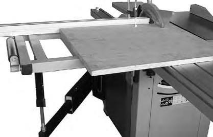
Install the extension table
Take out the cast iron extension table, steel plate extension table and rear extension table from the Saw Base Unite crate.
The cast iron extension table is heavy part that weighs over 35 kgs. To be safer, you will need assistance.
1. Attach the Cast iron extension table to major table with 4-M8x20 hex head screws/ washers. 2. Center the extension table over the edges and tap it. Check the surface alignment.
Tighten 4-screws with 13 mm open head wrench.
Attach the steel plate extension table to cast iron extension table, Aligned and tighten them as “install the cast iron extension table”.
3.
Fig 1
Fig 4
Fig 2
Table Wood Block
Major Table
Fig 3
Install the support leg
1. Attach the support leg to steel plate extension table with 2-M8x20 Hex head screws, washers and nuts. And tighten them.
2. Adjust the support leg ensure the steel plate extension table at the same lever with the cast iron extension table.
Install the rip fence rail
1. Place 5-M8x25 square head screws, washers and hex nuts onto major table and extension tables (washers and nuts inside table). The nuts only need to be turn a few turn so there is an adequate gap to fit
Install the rear extension table the rip fence rail.
2. Remove the left end cap of rip fence rail. Slide the slot on the rip fence rail over 5-bolts. Adjust each bolt
to fit the rail closely to table.
3. Push the rail against the tables and hand tight each hex nut. The rail needs further adjustment.
4. Put the left end cap onto rail, and tighten it with taping screws.
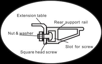
Install the rear support rail
Attach the rear support rail onto the cast iron and steel plate extension tables, with 4-M8x25 square head screws, washers and nuts, tighten them.
1. Attach the rear extension table to the rear portion of major table with 2-M8x16 hex head screws washers, hex nuts.
2. Place the bracket onto rear panel of saw base unit with a M8x16 hex head screw, another end of bracket
mounted to rear extension table with a M8x16 hex head screw.
3. Align the rear extension 0.5mm lower than themajor table.
Install the main blade elevation & angle handwheel
1. Fitting the elevation handwheel(1) and angle handwheel (2) onto the elevation and angle shaft.
Rip Fence Rail
Fig 5
Support Leg
Rip Fence Rail
Fig 8
Fitting the rip fence and align the rail
1. Move the blade tilt to 0˚ (blade 90˚ to table), and raise the main blade as the way up.
2. Fit the profile of the rip fence carrier into the opposite profile on the rip fence rail.
3. Slide the rip fence touch the main blade.
4. Tap the right end of rip fence rail to ensure the '0' scale on rail aligned with the red line on lens of rip fence carrier.
Install the swing arm assembly
1. Place 4 M8x30 hex head screws to mount the swing arm assembly to the saw base unit, and keep the arm on horizontal level.
2.Place the cross-cut table support (A) onto the swing arm assembly, and hand tighten the lock nuts. The support needs further adjustment.
Install the Sliding panel assembly
1. Place 2 sets of star-type screws (include8mm washer, insert, screw guide) into the lower slot of sliding panel carrier ( see above 14).
2. Put the sliding panel assembly onto the sliding panel supports, and lay two star-type screws as fig 15 show.
Install the support leg to the sliding carrier.
3. Tighten two star-type screws.
4.
Fig 10
Fig 12
Fig 14
Adjust the sliding panel level:
1. Place a level rule (cross cut fence) on to major table
Install the cross cut fence
1. Drop the cross cut fence into the forward or rear guide and sliding panel. pin hole.
2. Loosen 4-M8x25 hex screws(A) , adjust the M8x40 hex screw(B) to adjust the sliding panel level(fig 13).
3. Then re-tighten 4-M8x25 hex screws (A)
4. To fine adjust, using 3 mm “L” wrench to adjust 4-
2. Tighten the knurled nut.
3. Turn the “Z” lock plate to quick aligning the fenceto table.
4.Turn the star type screw and clamped the fence in M8x12 set screws(C) position.
Install the push handle and lock pin
1. Sliding the M12x1.75 T-nut into the sliding panel and
5. Slide the flip stop(D) intothe fence.
6.Place a T-nut into the top slot of fence, thread the thread in push handle(D) with a 17 mm open end stud of hold-down on fence. wrench.
2. Insert the star-type lock pin (E) into sliding panel, and lock the M10 hex nut on the opposite side.
Install the cross cut table
1. Slide two M8x70 carriage bolts with T-lblocks into the side slot of sliding panel. Attached the crosscut table to sliding panel.
2. Use 2 wing nuts mounted the cross cut table to sliding panel.
3. Use 2 M6x30 Hex head scews mounted the cross cut table to support(B)
4. Adjust 4-M12 thin hex nut (C) to adjust the cross cut table on the line with sliding panel.
5. Then tighten 4-M12 thin nut (C)
7.If need, put the hold down arm onto the stud (E).
Install the hold down/Mitre Gauge
1. Slide the hold down/Mitre Gauge onto the sliding table and push it as far as possible. And lock the hold down/mitre gauge on table with the star-type lock handle (A) locked.
2. Aligned the Mitre Gauge fence onit.
Fig 18
D Fig 15
Install the dust port
Place the dust port onto the bottom of rear panel,
tighten it with 4 M6x12 pan head screws washers and
Install dust hoses
1. Install the 2” dust hose onto the blade guard with 2” nuts (nuts inside stand). hose clamp.
Install the blade guard
The riving knife cuts 3 slot for different blade size.
For PS10 the blade guard mounts to the 254 slot.
For PS12, if using the 254 mm blade place the blade guard onto 254 slot; if using the 305 or 315 mm place the blade onto 315 slot.
2. Put the 2” dust hose onto dust hose support, keep free with the working table.
3. Another end of 2” dust hose clamps to the main dust port on the bottom of rear panel.
4. Install 4” dust hose to main dust port with 4” hose clamp
Install the dust hose support
To install the dust hose support onto the rear portion of steel plate extension table with 2 M6x20 hex head screws washers and nuts( nuts under the table).
Fig 19
Fig 22
Fig 24
Fig 20
Fig 23
Fig 21
REPLACEMENT & ADJUSTMENT
Replace the main blade
Disconnect the saw from the power source!
The main blade dimension suitable for MJ12 machine is 254x30x3( outer diameter, core diameter, thickness), 305x30x3, 315x30x3mm.
But any time you change blade thickness, the appropriate sized riving knife and scoring blade must also be changed to match the size of main blade you install.
To change main blade:
1. Move the blade tilt to 0˚ (Blade 90˚ to table) on the control panel and raise the blade as far as it will go.
2. Move the sliding panel all the way to the right and remove two M6x12 pan head screws to expose the
internal blade guard that covers theblades and
3. Remove the blade guard from the riving knife to expose the mounting assembly.
4. Remove the table insert.
5. Insert the arbor pin into the hole on blade inner flange and locks the blade.
6. Using the arbor wrench, remove the arbor nut that secures the main blade (turn clockwise to loosen).
7. Remove the arbor flange and the old main blade.
8. Install the new main blade, replace the arbor flange
Replace and adjusting the scoring blade
Disconnect the saw from the power source!
Suitable for machine is 90x20x3( outer diameter, core diameter, thickness) mm Tapered Scoring Blade.
To replace scoring blade:
1. Move the blade tilt to 0˚ (Blade 90˚ to table) on the control panel and raise the blade as far as it will go.
2. Move the sliding panel all the way to the left and riving knife. remove two M6x12 pan head screws to expose the
internal blade guard that covers the blades and riving knife.
3. Remove the blade guard from the riving knife to expose the mounting assembly.
4. Remove the table insert.
5. Insert the arbor pin into the hole on blade inner flange and locks the blade.
6. Using the arbor wrench, remove the arbor nut that secures the main blade (turn anti-clockwise to loosen). and nut, and tighten the arbor nut to secure the
main blade.
If you changed blade diameter sizes during this procedure, now is the time to adjust the riving knife. (Just for MJ12 )
If the kerf thickness is different from your old blade, the scoring blade kerf and riving knife thickness must match the new main blade kerf.
9. Make sure the correct size riving knife is installed and aligned with the blade.
10. Move the internal blade guard back into itsoriginal position, next to the blades, and center thesliding panel.
11. Align the scoring blade to the main blade
7 Remove the arbor flange and the old scoring blade.
8. Install the new scoring blade, replace the arbor flange and nut, and tighten the arbor nut to secure the scoring blade.
Fig 26
To align scoring blade:
Loosen the clamping screw (A). Lateral adjustment is made via adjusting screw (B). the height setting is made via setting screw (C). retighten the clamping screw (A). Adjust the scoring blade laterally so it is in line with the main sawblade.
Replace and adjust the riving knives
Disconnect the saw from the power source!
1.Move the blade tilt to 0˚ (Blade 90˚ to table) on the control panel and raise the blade as far as it will go.
2. Move the sliding panel all the way to the right and remove two M6x12 pan head screws to expose the internal blade guard that covers the blades and riving knife.
3.Remove the blade guard from the riving knifeto expose the mounting assembly.
4.Remove the center bolt in the mounting assembly to remove the mounting plate.
5.Remove the currently installed riving knife and install the correct riving knife.
6.Replace the mounting plate and thread inthe center bolt without completely tightening it.
The riving knife is carved with different blade size, just put the carved line under table.
The center carriage bolt is mounted in a horizontal slot, so the riving knife can move far or near the main blade.
7.Position the riving knife about 3mm to 8mm away from the nearest carbide tooth on the mainblade.
Note For a quick gauge, use the 3mm hex wrench to find the correct spacing between the blade and the riving knife.
8.Tighten the center bolt to secure the riving knife in position.
9.Move the internal blade guard (from step 4) back to its original position, and move the sliding panel back to center.
Replace the main belt
Disconnect the saw from the power source!
1.Move the blade tilt to 0˚ (Blade 90˚ to table) on the control panel and raise the blade as far as it will go.
2. Move the sliding panel all the way to the left and remove two M6x12 pan head screws to expose the internal blade guard that covers the blades and riving knife.
3.Remove the blade guard from the riving knife to expose the mounting assembly.
4. Remove the main blade.
5.Remove 3 M8x18 Allen screw and remove the chip house.
Note To remove lower 2-M8x18 Allen screws, the main blade angle system tilt to 30˚, to remove the upper 1-M8x18 Allen screw , the main blade angle system tilt to 0˚.
6. Remove the 4 Allen screws on the top and bottom of left panel, and remove the left panel.
7. Loosen motor amount 4-M8x40 hex head screws(A) and loosen the tension bolt(B).
8. Remove the V-belt.
9. Replace new V-belt, tighten motor bolts and the tension bolt, close the left panel, and re-mount blade inner guard, blade, blade guard. Fig 28 3- 8mm
Fig 29
2. Raise the main blade up as far as it will go.
Replace the scoring belt
Disconnect the saw from the power source!
1. Move the blade tilt to 0˚ (Blade 90˚ to table) on the control panel and lower the blade as far as it will go.
2.Remove the 4 Allen screws on the top and bottom of right panel, and remove the left panel.
3.Push the tension pulley as far as it will go as arrow show.
4. Remove the old belt and replacenew belt.
5. Re-mount the right panel.
3. Mark the center of the blade with a felt tip pen. This will allow you to take your measurements from the exact same place on the blade.
4.Move the sliding panel all the way to one end, and using a precision ruler, measure the gap between the edge of the panel and your mark on the blade as shown in Fig 32.
Sliding Table
Mitre Slot B A
5. Move the other end of the sliding panel in front of the blade and measure the gap.
If the gap is the same on both sides, then the sliding panel is already parallel with the main blade.
If the gap on one side is different than the other, then continue with step6
Sliding Panel Parallel Adjustment
Disconnect the saw from the power source!
Now is the point in the assembly process to make the sliding panel parallel with the main saw blade and secure the sliding panel to the saw base.
Besides the tools included with the saw, this procedure
6. Move the end of the sliding panel that needs to be adjusted in front of the blade.
7. Loosen the two hex head screws (C) and light tap the sliding carrier support to adjust the gap.
8. Repeat steps 7 until the gap between your mark on requires you to have a precision ruler, a felt tip pen, and the blade and the edge of the sliding panel is even at the assistance of another person. both ends.
To adjust the sliding panel parallel with the main blade:
1. Set the blade to 0˚ on the control panel (90˚ with the cast iron table).
9. Tighten the four hex head screws (C) andsecure supports in place
10. Now tighten the two star-type screws that secure the sliding panel to the base.
Fig 31
OPERATIONS
Your safety is important. To preventing work-piece kickback, slide the edge shoe into sliding panel when needed.
The edge shoe can slide into the front or rear portion of sliding panel.
Rip Cutting
The sliding panel saw has the capability of rip cutting full size panels. The sliding panel removes the burden
of sliding a large and heavy panel overa stationary
table surface.
This saw also has the capability of ripcutting smaller
3. Install the crosscut fence in the guide pin holes and lock it in place with the knurled nut.
Note First, drop the crosscut fence into the forward guide pin hole, turn the "Z"lock plate to align the fence, then tighten the knurled nut
4. Set either flip stop to the desired width-of-cut.
5. Load the workpiece onto the table saw.
6. Mount the hold down arm onto the stud and lock the work-piece in place.
7. Once all the necessary safety precautions have been taken, perform the cutting operation.
Rip cutting using the traditional table saw technique:
1. Slide the crosscut table out of the way.
2. Lock the sliding panel into a stationary position.
3. Position the rip fence to the desired width-of-cut.
4. Once all the necessary safety precautions havebeen boards, using the machine as a traditional table saw. taken, load the workpiece onto the table saw and Smaller, lighter boards are easier to slide across the perform the cutting operation. stationary cast iron table surface to the right of the saw blade.
Determine which cutting operation will be best suited for the workpiece to be ripped.
To use the sliding table, read the instructions titled “Rip cutting with the sliding panel.”
To use the machine as a traditional table saw, skip ahead to “Rip cutting using the traditional table saw technique.”
Rip cutting with the sliding panel:
1. Mount the crosscut table to the sliding panel.
2. Slide and secure the crosscut table to the end of the sliding table opposite the sliding table handle.
Crosscutting
With the crosscut fence mounted in the forward position, the sliding panel saw has the capability of crosscutting full size panels.
With the crosscut fence mounted in the rear position, this machine also has the capability of crosscutting smaller panels.
Fig 38
Fig 39
Fig 36
Fig 34
Fig 35
This machine has the capability of crosscutting workpieces while using the hold down w/mitre gauge.
Lastly, this machine has the capability of crosscutting
workpieces while using the rip fenceas a cut-off gauge.
Determine which cutting operation will be best suited
5. Mount the hold down arm onto the stud and lock the work-piece in place.
6. Once all the necessary safety precautions have been taken, perform the cutting operation.
Crosscutting smaller panels:
1. Mount the crosscut table to the sliding panel.
2. Install the crosscut fence in the rear guide pinholes and lock it in place.
Note First, drop the crosscut fence into the rear guide pin hole, turn the "Z"lock plate to align the fence, then tighten the knurled nut
3. Set either flip stop to the desired width-of-cut.
Note If the workpiece extends to the left of the saw blade more than 1200mm, then the crosscut fence slide needs to be extended.
4. Load the workpiece onto the table saw. for the workpiece to be crosscut.
5. Mount the hold down arm onto the stud and lock the
If you will be crosscutting full size panels, then skip work-piece in place. ahead to “Crosscutting full size panels.”
6. Once all the necessary safety precautions have been If you will be crosscutting smaller panels, then skip taken, perform the cutting operation. ahead to “Crosscutting smaller panels.”
If you will be crosscutting workpieces using the hold
Crosscutting using the hold down: down, then skip ahead to “Crosscutting using the
1. Mount the hold down onto the sliding panel. hold down w/mitre gauge.”
If you will be crosscutting workpieces using the rip fence as a cut-off gauge, then skip ahead to “Crosscutting using the rip fence as a cut-off gauge.”
Crosscutting full size panels:
1. Mount the crosscut table to the sliding panel.
2. Install the crosscut fence in the forward guide pin holes and lock it in place.
Note First, drop the crosscut fence into the forward guide pin hole, turn the "Z"lock plate to align the fence, then tighten the knurled nut
3. Set either flip stop to the desired width-of-cut.
Note If the workpiece extends to the left of the saw
blade more than 1200mm, then the crosscut fence
2. Load the workpiece onto the table saw. Secure it using clamp.
3. Once all the necessary safety precautions have been taken, perform the cutting operation.
Crosscutting using the rip fence as a cut-off gauge:
1. Mount the crosscut table to the sliding panel.
2. Install the crosscut fence in the rear guide pin holes and lock it in place.
Note First, drop the crosscut fence into the rear guide pin hole, turn the "Z"lock plate to align the fence, then tighten the knurled nut
3. Position the rip fence to the desired width-of-cut.
4. Load the workpiece onto the tablesaw.
5 Mount the hold down arm onto the stud and lock the slide needs to be extended. work-piece in place.
4. Load the workpiece onto the table saw.
6. Once all the necessary safety precautions have been taken, perform the cutting operation.
Miter Cutting
Note If the workpiece extends to the left of the saw
The cross cut table built two scales for forward and rear blade more than 1200mm, then the crosscut fence mount fence to perform mitre cut. slide needs to be extended.
Also the sliding panel built a scale for hold down to
4. Load the workpiece onto the tablesaw.
5. Mount the hold down arm onto the stud and lock the work-piece in place.
6. Once all the necessary safety precautions have been taken, perform the cutting operation.
To perform a miter cut using the hold down w/mitre gauge:
1. Mount the hold down onto sliding panel and fit a cut fence.
2. Position the hold down w/mitre gauge at the perform mitre cut. desired angle and use the ratchet lever to lock the mitre gauge in position.
Lastly, this machine has the capacity of mitre cutting work-piece using the mitre gauge.
To perform a miter cut using the cross cut fence:
1. Mount the cross cut fence onto the cross cut table.
2. Position the cross cut fence at the desired angle and use the ratchet lever to lock the cross cut fence in position.
3. Load the workpiece onto the sliding panel. Secure the workpiece with clamp.
4. Once all the necessary safety precautions have been taken, perform the cutting operation.
3.Position the flip stop according to the length of the workpieceyou want to cut off to the left of the blade.
Fig 44
Fig 41
Fig 46
Fig 45