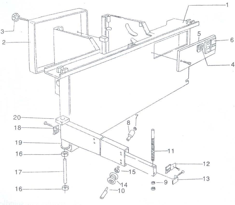
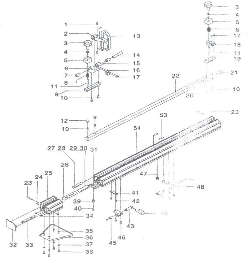
2. Technical data
2.1 Machine identification
The typelabel attached to the machine stand isused todetermine the machine identity andfurther important key data.
Meaning of the specified designations:
Type: Machine designation
Number: Machine-specific identification number
Year of manufacture: Year of manufacture
Saw blade min Ø: Diameter of the smallestpermitted saw blade
Saw blade max Ø: Diameter of the largestpermitted saw blade
The name plate on the machine frame plays a role as the machine mark and offers important parameters of the machine.
Meanings of the name plate contents.
Check character
To document that the machine complies with the basic health and safety requirements as defined in Appendix I of Guideline 98/37/EWG for modifying Guideline 89/392/EWG (operator´s manual)the machine is identified by the CE symbol.
2.3 Noise characteristic values
Emitted noise level [dB (A)]
Idle LWA= 98,3
Operating LWA = 103,2
Emitted noise level at the work - place [dB (A)]
Idle LPA = 91,0
Operating LPA = 94,4
Tool
Saw blade 315 x 3,2 / 60 WZ
Rated speed = 4405 rpm
For the emission figures stated a measurement tolerance of K = 4 dB (A) applies.
The specified figures are emission levels and therefore not necessarily the level for safe working.Although there is a relationship between emission and immission level there is no reliable method of deriving from this whether additional precautionary measures are required to protect the user.The factors that influence the current level of immission present at the workplace include the length of exposure, other sources of noise such as neighboring machines and their numbers for example or other processing operations linked to noise emission. In addition the level for assessing noise can differ from country to country. Despite this information is suitable for enabling the user of the machine to obtain a better estimation of the danger and the risk.
2.4 Dust emission data
In accordance with the "Principles for Testing Dust Emission (work place based dust concentration) of Woodworking Machines" issued by the trade association "Wood", the dust emission values measured are under 2 mg/m3. Thus, when the machine is connected to a correctly operating extraction system with an air speed of least 20 m/s, measured after joining both connection sockets, a permanent, safe maintenance of the dust emission value for wood dust prescribed in Germany is guaranteed.
For this reason the machines also bear the GS symbol with the additional clause "wood dust tested". On the basis of TRGS 553, this exempts the owner from obligatorily testing at the workingplace of these machines.
2.5 Intended use
The sliding table saw series and the workpiece guide equipment supplied is intended exclusivelyto be used for the following purposes:
Cutting laminated and unlaminated sheet materials such as chipboard, woodworkingboards, MDF boards and material to be processed in a similar way
Solid wood
Veneer with suitable clamping
Gypsum
Paperboard
Processing of other materials such as nonferrous metals and composite
materials made of NF metals and plastics requires our approval as regards the approval of the individual material and the saw blade intended for cutting it.
Only use the machine to cut pieces which can be securely held and guided.
Saw blades:
Care should be taken to choose the correct saw blade for the job, which will depend (for example) on whether you are ripping or crosscutting and the type of material being cut!
Only one-piece (CV) or composite (HM) circular saw blades of at least 250mm and maximum 315 mm diameter as well as routers/milling blades up to a cutting width of 15 mm are allowed for the main saw
Blade:
For the scoring blades saw blades of maximum 120 mm diameter are allowed
The use of HSS saw blades and oscillating router equipment is not allowed
Site/use:
The machine is not suitable for operation in the open air, in damp environments or in areaswhere there is a danger of explosion
Use of the machine according to specifications also includes connection to a suitably dimensioned industrial extraction system
Adherence to the manufacturer’s specifications as regards operating, maintenance and servicing conditions and following the safety precautions given in the Operator´s manual
Sliding table saw series may only be used, equipped and maintained by persons who are familiar with the unit and have been instructed in the dangers involved. Responsibilities for use, equipping and maintenance must be clearly defined. Service work must be carriedout by our service department.
The applicable accident prevention regulations as well as the other generally recognizedsafety and medical rules applying to the workplace are to be noted
Only original factory spare parts may be used. The manufacturer does not accept any liability for damage caused by using non-original spare parts. Modifications made to the machine by users and the use of non-original parts on the machine exclude any liability by the manufacturer for any resulting damage
Machine workstations:
In line with specifications the sliding table saw will be operated from the following workplaces:
at the workstation on the left-hand side of the sliding table view in the direction of feed in the front part of the machine (main workstation)
on the front opposite side of the machine to the right of the sliding table when working withthe rip fence
The space for any workpiece acceptor is on the rear opposite side of the machine behindthe table length extension, not under any circumstance in the area of travel of the slidingtable and the telescopic tube of the swivel arm! Otherwise there is a danger of injury through impact in the knee area!
Important information:
– Any other use which goes beyond this is taken as not in accordance with specifications. The manufacturer is not liable for any damage that may result; the risk is borne by the user alone.
– Modifications made to the machine by users and the use of non-original parts on the machine exclude any liability by the manufacturer for any resulting damage.
3. Safety
3.1 Explanation of symbols
You will find this symbol all information relating to health and safety in this Operator’s manual where there is a danger to life and limb. Please read this information carefully and take particularcare in these cases. Please pass the safety information on to other users. As well as the informationinthisguidethegenerally-applicablesafetyandaccidentpreventioninstructions mustbe noted.
3.2 Health and safety instructions
Operating any machine tool, in particular woodworking machines with manual feed, involves a high risk if the machine is operated incorrectly. For this reason please always comply with the safety instructions summarized in this chapter as we as with official and other regulations governing health and safety at work (e.g. accident prevention regulations)!
Never operate the machine without using the protective equipment provided for the procedure involved (see also the section entitled "Safe use of the sliding table saw (- working examples -)" and do not change anything that could affect safety.
Check before working with the machine that the protective and operating equipment is securely attached and not damaged.
Before changing tools, rectifying faults and during regular servicing work ensure that the machine cannot be turned on by mistake by securing the main switch with a padlock.
Only saw blades and routing tools corresponding to European Norm EN 847-1 may be used.
Only saw blades with the dimensions described in Table 1 may be fitted. The diameter ofthe mounting hole must be 30 mm in any event. Use of loose spacing rings is not permitted.
The speed must be chosen so that the highest reliable speed when the tool is equipped with hard metal saw blades or routing cutters is not exceeded.
The use of HSS saw blades and cracked or reformed saw blades is not permitted.
Always wear working clothes and remove rings, bracelets and watches.
Ensure that the workplace is unobstructed and that nothing slides around and that there is sufficient lighting.
Do not work on any work pieces that are too large or too small for the power of the machine.
Take up a working position so that you are always standing to the side of the saw blade outside a possible recoil area (area directly in front of the saw blade).
Before the machine is switched on loose parts must be removed from the immediate vicinity of the saw blades.
Only start cutting when the saw blade has reached its full speed. Always use the upper safety hood.
The upper safety hood must be set to the height that matches the thickness of the workpiece to be cut. When working with a tilted saw blade replace the narrow hood with the wide hood.
Always use the riving knife except for insert cuts. It may not be thicker than the width of the cut and thinner than the master blade. It is to be set so that the gap to the tooth tip is a maximum of 8 mm. Only riving knives may be used for which the slot width does not exceed13+0.5mm.Thesuppliedrivingknifecoverstheentirediameterrange of the sawblades that can be used from 250 to 350 mm. As regardstheir thickness they are matchedto the commercially-available carbide tipped saw blades that are as wide as the cut. If other saw blades, e.g. CV saw blades are used, the width of riving knife necessary must be selected so that this lies between the cut width and the main blade width. This type ofriving knife is available in the trade of directly from us.
For cutting inserts a recoil protector should be used, e.g. the front side of the clamping shoe. This is to be attached in the groove of the sliding table whereby the carriage with the clamp must be secured so that it does not move. After insert cutting the riving knife and the upper safety hood are to be refitted immediately.
Always ensure secure work piece guidance and use the appropriate fences (rip fence, fence scale, crosscut fence on cross slides, cross stop).
For lengthwise cutting of narrow work pieces (gap between saw blade and rip fence smaller than 120 mm) the push stick must be used.
Only make crosscuts with the cross slides attached to the sliding table. Ensure that the cut-off work pieces are not caught by the rising tooth tip and catapulted out.
Electrical locking of the cover plate on the dust channel below the machine table in the area of the saw blades. When the cover plate is open it is not possible to turn on the machine and when the machine is running the drives are switched off if the cover plate isopened.
Automatic brake which stops the main saw blade in less than 10 seconds after the machine is switched off, regardless of the diameter and speed of the blade.
Enhanced flow design of the sawdust catcher and of the upper safety hood to reduce dustemission below 2 mg/m³, provided the machine is connected at both extraction sockets toan industrial extraction system with at least 20 m/s air speed.
Good ergonomic design of the controls in easy-to-reach positions on the machine stand.
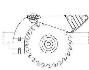
3.3.1 Safety hood mounted at the riving knife
To protect the saw blade above the table, there must be an adjustable removable protection device.
3.3.2 Riving knife
The correct setting of the riving knife plays an important role as far as safety is concerned. The distance of the riving knife to the toothed ring in the area of the cutting height may not exceed 8 mm. The most practical distance is approx. 5 mm. When positively guided riving knifes are used,this distance automatically ensures that the height setting of the riving knife with the tip approx. 2mm below the top tooth is also correct.
3.3.3 Table length extension
The table length extension prevents the work piece tipping over after cutting and makes workingsafer.
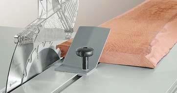
3.3.4 Clamping shoe
The clamping shoe is used for trimming planks and fixes the work piece securely on the sliding table
3.3.5 Push stick
For cuts less than 120 mm the push stick must be used to prevent your hands getting near the saw blade when working. The push stick holder is located close to the work area on the rip fence.
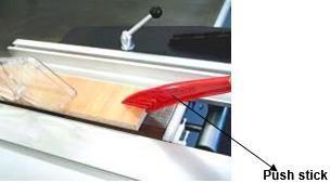
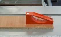
3.3.6 Push block (through-sawing)
Push blocks should be used for cutting narrower work pieces and if necessary, for pressing the work piece against the fence. A push block can easily be made by the operator and be fitted withthe push block handle suppled with the machine.
3.3.7 Kickback
Do not use the crosscut fence and the rip fence at the same time. Use of both fences at once cancause the material to bind on the saw blade, resulting in a kick back.
3.3.8 Freehand
Do not cut freehand, use a hand or clamping devices for fixing the workpiece.
3.4 Other risks
Even when the machine is used in accordance with specifications, despite compliance with all safety regulations, because of the construction of the machine which is determined by the purposefor which it is used, the following risks might still arise:
Touching the main saw blade and the scoring saw blade in the cutting area.
Touching the main saw blade and of the scoring saw blade below the table level when thesliding table is right forward or right back.
Backstroke of the workpiece or of parts of the workpiece.
Catapulting off of individual teeth with carbide-tipped saw blades.
Breakage and spinning off of the saw blade.
Sticking between the motorized tilt movement of the saw blade and the rip fence orworkpieces located in the tilt area.
Contact with live parts when electrical installations are open
Long-term effects of noise when working for long periods without hearing protection
Emission of dust that can damage your health if operating the machine without dustextraction.
Avoid any dangers that may arise from these other risks by taking extra care when settingup, operating and maintaining the machine!
3.5 Working safely with the sliding table saw
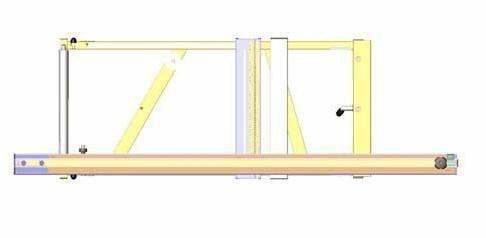
3.5.1 Cross slide fenceSizing and mitre cutting
The cross slide is placed on the end bolts of the swivel arm and the circular bar of the upper carriage and clamped with the clamping screws. Depending on the size of the material to be handled this can be done at any point on the upper carriage. For the mitre fence there are twopositions on the cross slide.
Position 1
Use: For handling boards
The operator pushes the workpiece in the cutting direction against the fence
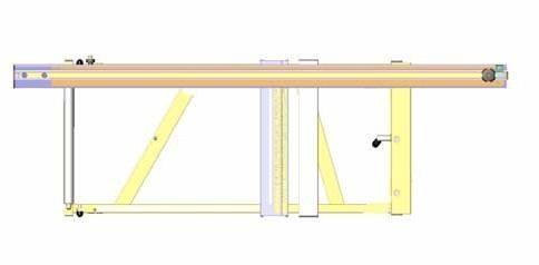
Position 2
Use: For handling wood and boards up to 600 mm width
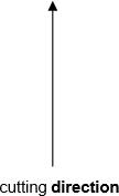
The operator pulls the workpiece against the cutting direction to the fence
3.5.2 Crosscut-mitre fence

Function description – Crosscut mitre fence adjustable to an angle of 49°, angle displayed onscale
Additional clamping in the 90° position
Movable C-profile that can be locked into position as additional workpiece support
Controls
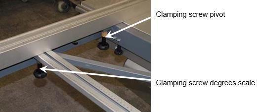
Changing the mitre fence:
Release the clamping screw degrees scale
Unscrew the clamping screw pivot
Move the mitre fence into the 2nd position
Screw the clamping screw pivot back
Tighten the clamping screw
Setting the angle
Release the clamping screw
Set the mitre fence to the angle and tighten the clamping screw
Note:
For dimensions that have to be set with the hinged bar it should be noted that the individualtilt stop is actually against the fence of the cutout!
3.5.3 Rip fence
Adjustment For parallel cutting the rip fence is set to the desired dimension. The dimension setis readoff via theedgeof thealuminum profilebar.The scalecanbeadjusted inaccordance withthe relevant tool thickness after the clamping screw has been released.
For cuts less than 120 mm wide the material must be fed with a push stick and the extendedfence must be in a flat position.
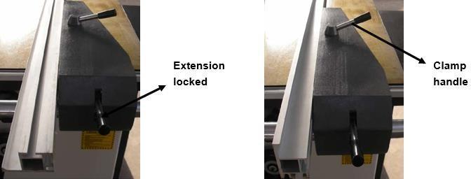
The extended fence of the rip fence is adjustable in the cutting direction and in the profile height.It is clamped in the desired position using a star knob screw.
Crosscutting For crosscutting shorter workpieces, for removal (e.g. tenon cutting) or other procedures in which pieces falling off could jam between fence and saw blade, the extension fence is pulled far enough forward for its rear end to be in front of the saw blade.
Flat and narrow workpieces
When handling flat and narrow workpieces the flat extension fence is used. This gives more spaceto guide the workpiece and the fence can be positioned closer to the saw blade, especially whenthe saw blade is tilted, without hitting the safety hood. Flat position of the extension fence
3.5.4 Working examplesGeneral
Then sliding table saw series is a universal machine which can be used for different cutting jobs.To do this however it is necessary to equip the machine accordingly.
Tool
The first important point is to only use undamaged saw blades, to correctly ad- just the riving knifeand to move the upper safety hood so that it is positioned closely above the workpiece to be cut.This last point is also of great importance for correct functioning of the extraction facility mentionedabove.
Speed
Ensure that the correct speed is set and after switching on the machine, only begin to push the workpiece forward when the saw blade has reached full speed.
Position of hands
The hands lie flat with the fingers closed on the workpiece; the thumbs are adjacent with a sufficient safety margin to the saw blade.
You will find further notes on safe working in the following description of the individual work processes.
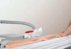
Edge cutting (trimming)
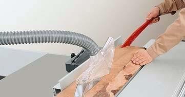
Ripping of narrow
workpieces(workpiece width
< 120 mm) Tool: Ripping circular saw blade.
Operation: Adjust rip fence to the desired cutting width. Lower the safety hood in accordance with the height of the workpiece. Move workpiece against the fence with the sliding table; use the push stick in thearea of the saw blade and push the separated workpiece until it is beyond the riving knife. For short work-pieces use the push stick right from the start.
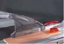
Cutting of strips
Tool: Circular saw blade for fine cutting.
Operation: Set the aluminum scale of the rip fence to the lower guide surface. Place the workpiece on the sliding table and use your left hand to push it against the rip fence.
Move the workpiece forward with the sliding table, using thepush block in the area of the saw blade and continue to push the strip until it is beyond the rivingknife.
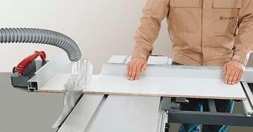
Crosscutting of wide workpieces
Tool: Circular saw crosscut blade
Operation: Place the workpiece against the mitre fence, usethe left hand to press it firmly against the fence while movingit forward.When the flip stop is used, this is to be flipped up
before pulling the workpiece back after cutting and the workpiece withdrawn from the saw blade or the workpiece is only to be removed beyond the rising blade tip.
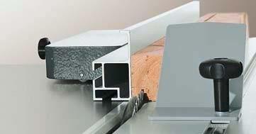
Rebating
Tool: Circular saw blade for fine cutting
Operation: For rebating select the cutting sequence so thatthe strip cut out falls away on the side of the saw blade opposite to the fence. Lower the safety hood onto the workpiece and ensure good workpiece guidance (left hand pushes the workpiece against the rip fence.)
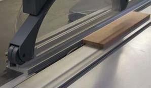
Concealed cutting, routing
Tool: Milling router permitted for manual feeding (maximum width 15 mm). Operation: Close the table opening by a table strip matched to the milling router. Set the tool to the desired routing depth. Leave the riving knife and the rear tool cover in place. On feeding push the workpiece firmly onto the table (otherwise there is the danger of an unintentional insert process). For crossrouting of narrow workpieces always use the mitre fence.
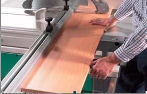
Crosscutting against the rip fence
The material is laid against the mitre fence of the cross slide. The desired dimension is set on the rip fence, the extension fence is pulled back to in front of the saw bladeafter unclamping it and the item to be cut moved with the sliding table. With the extension fence withdrawn the workpiece cannot stick between saw blade and fence.
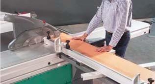
Crosscutting short and narrow workpieces
Tool: Circular saw blade for fine cutting.
Operation: Set the magnetic guide piece (not included withthe machine) so that workpiece offcuts cannot come into contact with the rising part of the saw blade. Onlyfeed theworkpiece using the mitre fence. Do not remove fallen pieces from the vicinity of the tool with your hands.
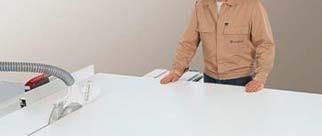
Dividing up large boards
With this operation the dimension can be set either at the rip fence or at the mitre fence. If you wish to cut out manypieces with the same dimensions from a larger board, thebest way to proceed is to first cut off parallel strips at the rip fence and then cut these to the desired dimensions.
However as soon as the part pieces are greater than the cutting width of the machine the dimension is set at the mitre fence of the machine.
4. Transport
When transporting the sliding table saw with a crane or fork lift (only fixed length forks) only lift the machine a little and protect it from shocks!
4.1
Packing
The form of packing depends on the transportation method and distance, if no requirement undercontract, the packing shall be executed according to the relevant regulations on machine tool export packing of the state, and attention shall be paid to the marks on outside of packing.
4.2
Degree of dismantling
The degree to which the sliding table sawis dismantled is governed by the transport conditions and by the options available on the machine.
Basically the sliding table saw is delivered divided into a number of installation modules.
4.3
Sensitivity
Particular care should be taken when transporting the sliding table saw to prevent damage from external forces or lack of care when loading and unloading.
During transport buildup of condensation as a result of variations in temperature as well as shocksare to be avoided.
4.4
Storage
If the sliding table saw or the assembly modules are not assembled immediately after delivery they must be carefully stored at a protected location.
When this is done they should be correctly covered so that no dust and no moisture can get in.
The sliding table saw is delivered with a preservative for the bare, non-surface treated parts whichprotects these parts for around 1 year. If it is stored beyond this period further preservation measures should be undertaken.
The distribution box of sliding table saw is mounted on the rear side of machine body and has output line. There is a terminal box on the side and it only needs to connect according to the mark.

After the lead is connected the direction of rotation of the main saw motor is to be checkedby briefly turning the machine on and if necessary corrected by swapping two external leads in the mains connection box.
Note the arrow indicating direction of rotation on the saw blade cover! 25A fuses are to beprovided on the operating side.

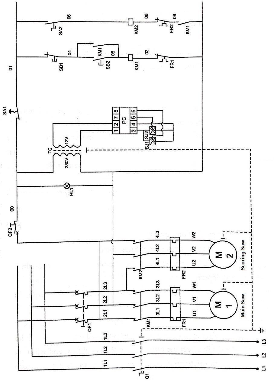
Annex 1 (This circuit diagram is suitable for three-phase circuit diagram of nonelectromagnetic brake.)
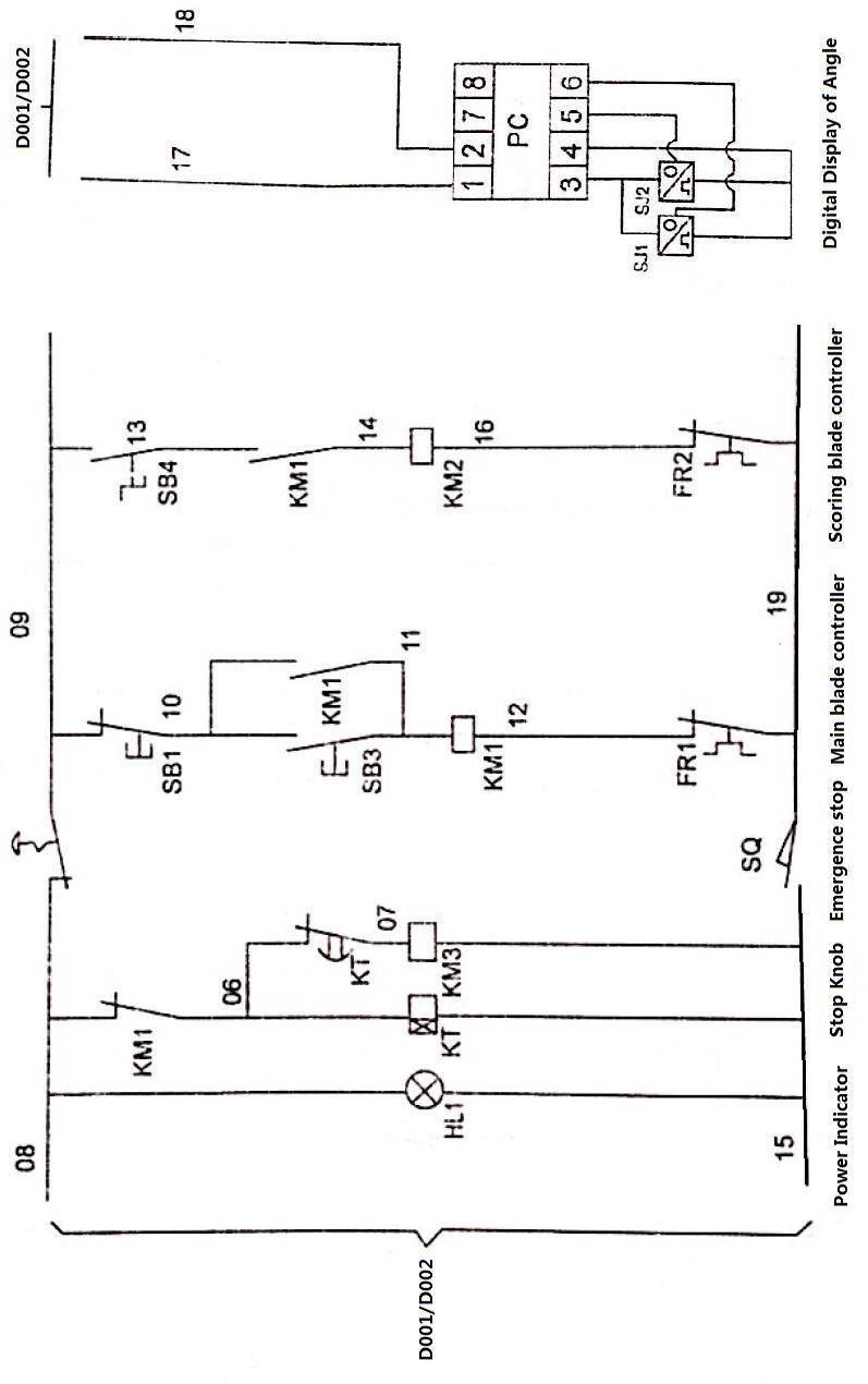
Annex3 (This circuit diagram is suitable for electromagnetic brake.)
Annex 5 (This circuit diagram is suitable is single-phase motor with electromagneticbrake.)

Checking the main table
Main table
Place a straightedge on the sliding table, carriage in mid position. Move carriage backwards andforwards, main table must lie about 1/10mm lower.
Adjustment of the main table
Loosen the locknuts on the 4 fixed bolts, adjust the table plate, tighten the nuts. Then lay the straightedge in parallel to the sliding table on the main table.
6.1 Free cut adjustment of sliding table
CheckingFree cut adjustment of sliding table
Set saw blade to max. cutting height, cut a short piece of a test piece (where possible MDF) at the mitre fence. The difference in the noise between the cutting and non-cutting teeth allows youto determine whether the sliding table is set correctly. On the passage of the rising teeth a slight fluttering noise should be heard compared to the noise of the cutting teeth.
Adjustment
Release the sliding table attachment at both ends and in the middle (where present). Release thelock nuts on the fence screws. Make the appropriate adjustments and retighten the lock nuts. Then readjust the sliding table and tighten all securing screws again
6.2 Free cut adjustment of rip fence
CheckingFree cut adjustment of rip fence
Set saw blade to max. cutting height, cut a short piece of a test piece (where possible MDF) at the mitre fence. The difference in the noise between the cutting and non-cutting teeth allows youto determine whether the sliding table is set correctly. On the passage of the rising teeth a slightfluttering noise should be heard compared to the noise of the cutting teeth.
Adjustment
Release the bolts connecting the table extension to the circular rod. Then, by adjusting the centerlocknuts, change the position of the circular bar and thereby of the rip fence.
When a scorer is used ensure that both free cuts are set to approximately the same!
6.3 Adjustment angle cut
CheckingAngle cut
Before the angle cut is checked the adjustment of the sliding table must be checked and correctedif necessary.
The angle cut is checked at the mitre fence as follows:
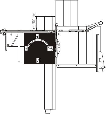
A sharp quality saw blade, D = 350 mm/ 3.5/2.5/72 teeth alternate teeth, at n=5000 1/Min is usedas a tool. Take a 1000x1000 mm plank or sheet of MDF, thickness at least 19 mm. Make 5 cuts (see Fig.), laying the last cut side against the mitre fence for the next cut (turn the board in a counterclockwise direction). On the 5th cut, cut off a strip about 10 mm wide. Measure the widthof the strip at both ends with a gage. The difference between the two dimensions divided by 4 gives the angular error per meter cutting length
Adjustment
The mitrefence is clamped in the position shown in the illustration (appr. 300 mm from the end ofthe table) and in a further position (appr. 1300 mm from the end of the table). In these two positionsthe angle cut is checked and adjusted, as described above. The adjustment may not exceed an allowable max. tolerance of < 0.2 mm
6.4 0° position of the saw
bladeChecking
Lay 2 strips (appr. 70 mm wide) on edge in front of the mitre fence, cut them in this position and push the cut surfaces together. If the setting is exact, the cut edges are parallel, i.e. there is no air gap detectable between the cut edges.
Adjustment
Recalibrate the machine!
7. Machine operation
The raise on lower the saw blade: it just needs to adjust the up/down handwheel on the right sideof the machine body.
To reduce or enlarge the angle: adjust the angel handwheel in the front of machine, and turn rightis to enlarge angle, while turn left is to reduce.
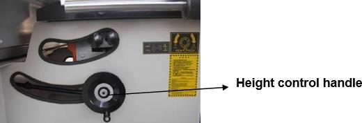
Height adjustment

Angle adjustment
Angle control handwheel has a 0-45° display attached to the push button plate for displaying thecurrent angle value.


