2. Main uses, performance and characteristics of the machine
This machine is suitable for cutting ordinary steel plates with a thickness of 0.6-6 mm and a width of 2500, 3200, and 4000 mm. The strength of the sheet to be sheared is based on 450N/mm2. If sheets of other strengths need to be sheared, the thickness of the sheet to be sheared should be adjusted accordingly.
This machine adopts steel plate welded body and slider. The fuselage and slider undergo vibration aging treatment to remove welding and machining stress to ensure the accuracy and accuracy of the machine tool are maintained. The shearing of the slider is driven by the hydraulic cylinder and the nitrogen cylinder returns, which can effectively realize the overload protection of the machine tool; the machine tool works stably, has a small size, light weight and good rigidity.
Adjusting the cutting edge gap is quick and convenient. The machine is equipped with front and rear stoppers, and the back stopper adopts mechanical transmission. The rotating display shows the value and can be manually fine-tuned. The adjustment is convenient and reliable. The front stopper uses a ruler to count and the stopper is positioned. In addition, the stroke of the upper tool rest can be adjusted arbitrarily to improve the efficiency of cutting narrow sheets. The machine is also equipped with a guardrail to ensure safe operation.
3. Machine hydraulic transmission system
The hydraulic system of the machine (see Figure 1) mainly consists of 10MCY141B axial piston pump 2, electromagnetic relief valve 3, pressure material 6, nitrogen return cylinder 7, main oil cylinder 8 and collar air reservoir 9. The entire system More reasonable.
The pressure oil required by the system is supplied by the 25MCY-1B axial piston pump 2. The maximum working pressure of the system is 20MPa. The return stroke of the upper tool rest is completed by a nitrogen cylinder, and the pressure of the nitrogen cylinder is about 5MPa.
Working principle of hydraulic system (see Figure 1)
The upper tool rest shears downward: When the electromagnet YV1 of the
electromagnetic relief valve 3 is electrically actuated, the oil output by the plunger pump 2 passes through the electromagnetic relief valve 3 and enters the pressure cylinder and the upper chamber of the main oil cylinder at the same time. When the piston of the pressing oil cylinder presses down to the sheet after overcoming the tension of the tension spring, the oil pressure begins to rise. When the oil pressure rises to overcome the nitrogen pressure of the return cylinder 7, the upper tool rest moves downward for shearing, and this process continues That is to say, the program action between the pressing cylinder 6 and the upper tool rest is realized.
Upper tool rest upward return stroke: When the upper tool rest moves down to the bottom dead center, the electromagnet YV1 of the electromagnetic relief valve 3 loses power under the action of the travel switch, and the upper tool rest begins its upward return journey under the action of the return nitrogen cylinder. At this time, the oil in the upper chamber of the main cylinder flows back to the fuel tank through the electromagnetic relief valve. At the same time, the piston of the pressure cylinder also returns upward under the action of the tension spring. The oil in the pressure cylinder also returns to the tank through the electromagnetic relief valve 3. When the upper tool rest returns to the starting point, the entire shearing process ends.
Hydraulic system faults and troubleshooting
Fault phenomenon cause
The oil circuit is established and cannot be pressurized
The tool holder does not move when the force is applied
Method of exclusion
Poor contact of the electrical plug of the electromagnetic reversing valve Repair electrical plugs
The valve core of the electromagnetic reversing valve is stuck or roughened by debris and does not operate. The sealing port of each valve core of the combination valve has debris and does not function as a seal. Each throttle hole in the combination valve is blocked.
The upper tool rest returns slowly or cannot return to the top dead center
The action sequence of the upper tool rest and the pressing cylinder is not coordinated
Insufficient nitrogen pressure in nitrogen cylinder
Check for disassembly and washing
Nitrogen cylinder charging increases pressure
Common hydraulic faults of QC12Y shearing machine
1. The valve core is clogged due to lack of pressure in the system. Disassemble the solenoid valve and regulating valve. Use the M8 screw to pull out the pressure plate. Take out the valve core spring. The valve sleeve does not need to be taken out. Clean it with gasoline, including the inside of the valve body. Clean and put it back as it is. If that doesn't work, clean the regulating valve and solenoid valve. Before cleaning, drain the oil inside the tank, clean the tank and filter it.
2. Check whether the main motor is fully started. Because the motor has high power, the starting mode is ▲ start.
3. According to "Electrician Inspection", the green light on the front operation panel is not on. "Motor power is above 18.5KW)
Hydraulic components detailed list
1 Mesh oil filter Q=160L/min WU 160×100-J
2
Axial piston pump P=32MPa Q=25L/min 25MCY14-1B Working pressure 18MPa
3 Combination valve self made
4 pressure gauge switch
5 pressure gauge
6 Solenoid directional valve
P=32MPa d=8mm KZF-L8H-S
P=25MPa φ=100mm Y-100-NZh
P=31.5MPa d=8mm SWH-G02-B2-E24-20
7 ball valve P=32MPa d=15mm CJZQ H15L
8 relief valve P=31.5MPa d=6mm F2ZB-H16F-4
9 inflation valve
10 pressure gauge P=16MPa Y-60-NZh Figure 1
4. Machine structure
1. Rack:
The frame structure is welded by steel plates and has good rigidity. The two cylinders are fixed on the left and right columns. There is an auxiliary tool rest on the workbench to facilitate micro-adjustment of the lower tool rest to ensure that the gap between the upper and lower blades on the machine tool is consistent. There is also a feeding roller ball installed on the work surface, which is easy to operate.
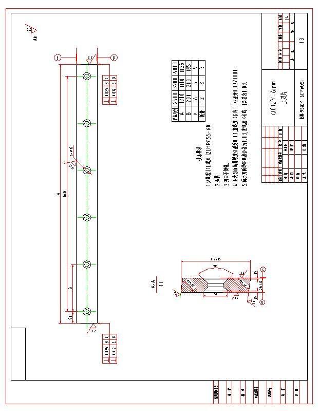
2. Upper tool rest: It is a steel plate welded structure with good rigidity. It uses the eccentric sleeve (9) as the fulcrum to swing back and forth to complete shearing driven by the left and right oil cylinders and the accumulator return cylinder. (Figure II)
The blade vertical supporting surface of the upper tool rest forms an arc-shaped backing plate to ensure the consistency of the gap between the upper and lower blades during the shearing process.
3. Pressing device: It consists of several pressing cylinders installed on the support plate in front of the frame. After the pressing cylinder is filled with oil, the pressing head presses against the tension of the tension spring (18) to compress the sheet. After shearing is completed, it is reset by the tension of the tension spring.
The size of the pressing force increases with the thickness of the sheared plate.
4. Front and rear stoppers:
Front stopper: Place it on the work surface and use a ruler to indicate the value to adjust the movable stopper to achieve the required stopper value. It is more convenient to use the front stopper when cutting thin steel plates.
The back gauge (see Figure 5) is installed on the upper tool rest and swings up and down with the upper tool rest. The adjustment of the back gauge is driven by a 0.55KW motor, which is driven by a screw rod after being reduced by gears. Press the adjustment button "+ ” (or “ - ” ), the baffle plate can be adjusted forward (or backward). When the motorized adjustment cannot reach the required adjustment value, the manual adjustment wheel (56) can be rotated for manual fine-tuning to ensure The required adjustment value, so the adjustment of the backgauge is convenient and reliable.
The adjustment range of the backgauge is 20~700mm. When the length of the sheet to be cut is greater than the maximum backgauge distance, the baffle plate (43) can be opened to the final position and passed through the slope on the bracket (47) Lift the baffle (43) to cut the sheet of any length.
5. Machine electrical system
This machine uses 50HZ, 380V three-phase power supply. The machine's motor uses single-phase 380V, and the alignment light uses single-phase 220V. The control transformer adopts two-phase 380V. The output 220V of the control transformer is used for the control circuit and alignment lights, of which 27V is supplied to the electromagnetic reversing valve. 6V supply indicator light.
The machine's telegraph box is located on the left side of the machine tool. The operating components of the machine, except for the foot switch SF, are all concentrated on the button station in front of the machine tool. The function of each operating procedure component is marked by an image symbol above it.
The machine operating sequence is described as follows: open the electrical box door, close the power switches QF1 and QF2, turn on the machine power, and close the electrical box door. Turn on the key button SA1 ( ) and turn on the control circuit power. The indicator light HL1 ( ) is on, indicating that the power is on.
Press button switch SB4 or SB5 ( ) to increase or decrease the backgauge opening to the required size. The specific size of the backgauge opening is displayed by the counter on the lower left side of the button. The maximum and minimum dimensions of the backgauge opening. It is equipped with a travel switch (SQ3 SQ4) to limit the maximum opening distance of the stopper to 500mm (600 mm) and the minimum opening distance to 20mm.
Press the button switch SB3 ( ) to start the oil pump motor. The button switch SB3 itself has an indicator light to prompt the oil pump motor to work.
Turn the knob switch SA3 ( ) to select the cutting specification. When SA3 is turned to the ( ) position, it is a "one stroke", and when SA3 is turned to the
Electrical code Name and purpose
SB 3 HL 2 Button oil pump 1《a》Green 1
SB 4 Stopper forward 1《a》black 1 LAY 3 -11
SB 5 control 1《a》black 1 LAY 3 -11
SB 1 Material blocking φ35mm red 2 LAY-11ZS/1 switch
SA SA SA 3 2 4 Cut continuous/single Alignment switch
SA 1 key switch
Single board 2 places
Single board 2 positions Vc=360 1th=6a2 "a"
( ) position, it is a "continuous stroke". When SA3 is in the first stroke position, press the foot switch once and the upper tool rest of the SF machine will cut downwards. Release the SF upper tool holder to stop shearing downward. and immediately rise to top dead center. Cut again and then depress SF. It must be noted that when the sheet is not completely cut, do not release the foot switch SF to prevent the sheet from being sheared. When SA3 is in the continuous stroke position, press the foot switch SF (the depressed The time should not be too long, otherwise it will become one cut) The machine will cut continuously. Turn SA3 to one stroke and continuous shearing will stop.
Turn the knob switch SA2 to one stroke, ( ) turns on the light, and the sheet to be sheared can be sheared by moving it. Turn the knob switch SA4 to the (1) position to start shearing counting, and turn it to the (0) position to stop shearing and counting.
Note: 1. The machine must be reliably grounded
2. When the knob switch SA3 is in the continuous position, the oil pump motor must be started first, and then the foot switch is pressed.
1 Time Relay
Electrical code Name and purpose
Fuse Holder With fuse core 3A With fuse core 2A With fuse core 4A With fuse core 2A With fuse core 2A With fuse core 2A
M 1 M 2
Three-phase AC asynchronous electric motor Oil pump motor
Back gauge motor
3-50HZ 220/380V 900r/mmE-class
7.5KW B 5 1500r/mm
0.55KW B 3 double output shaft
System usage instructions:
Reference point logarithm
1. : Press this key and the logarithmic indicator light will flash. Use a ruler to measure the current position of the rear gear. After inputting the value, press the again to return to the main state. picture.
Loop/single step logarithmic state. Press the logarithmic key
2. : In the single-step state, it can only run the current program. It only has the counting function to determine a certain number. The main tool rest or slider moves down once, and the number is subtracted once until the value is zero. The running light extinguished.
Press OK key to exit the
3. this button repeatedly, and the cycle light will turn on. When the current program running times is zero, it will immediately jump to the next program to run. This cycle repeats. To stop running, you need to press the run/stop , and the running light will go out.
Programming key
ENT the programming
4. : After pressing key, the words in the program box start to flash. At this time, you can enter the program number (0-9)tobechanged,then press toconfirm,then thecountcolumnflashes, enter the program number to be run. times, press to confirm, then the rear gear value column flashes, enter the required value, press to complete programming, and press key to exit.
5. program
6. : Press this button to immediately select the to be run or modified.
Manual mode description:
Run/Stopthe + Program selection the programming ENT again
: Press this button to immediately stop the motor, and press it again to start running the program.
Press key (when the running light is off), the rear gear box will flash and enter the manual state. Press the rear gear operation. or key again to start the
Press to stop the manual state: Press this key to select the program to be run or modified. ENT + Run/Stop again
6. Machine lifting and installation
1. Lift the machine according to the method shown in the lifting and lifting diagram (see Figure 10)
2. Basics of the machine:
① For foundation dimensions, please refer to the installation foundation diagram (see Figure 11)
② The soil around the foundation must be compacted, and the depth depends on the specific conditions of the soil.
3. Machine installation
When the machine is installed and fixed, the rolling ball cover on the work surface should be removed, use a one-meter ruler to measure on the two pads, and then use a level to make vertical and horizontal corrections so that the tolerance within every 1000mm should not be greater than 0.2mm.
7. Machine lubrication
1. Each main lubrication point of this machine adopts oil gun injection dispersion lubrication. The lubrication points are as follows:
Lubrication
point serial number Lubrication point name
One point each on theupper
1 and lower ends of the left Small 16 and right return cylinders
Lubricating oil types and brands
The swing fulcrum of the Calcium based grease
2 upper tool rest is one point each on the left and Small twenty four ZG 3 GB491 65 Machinery oil right. N46GB443 84B
One point on the left and 3 right of the gap Small 48 adjustment shaft bushing
4
One point each on the left and right cylinder piston rods middle 8
5 A little spacer for the left and right cylinders middle 8
4 #Graphite lithium grease Q/SY1000-65
Note: 1. Mix 50% calcium-based grease and 50% mechanical oil before use.
2. Graphite lithium grease must be mixed with 30% mechanical oil.
3. In principle, the oil in the fuel tank should be changed once every six months.
10 Machine lifting diagram
Figure
11 Installation foundation diagram
Figure
8. Machine adjustment and operation
1. Adjustment of cutting edge clearance:
Whether the blade gap adjustment is appropriate is an important factor that affects the shearing quality and extends the blade life. It is recommended to select the gap value according to the table below.
When adjusting the gap (see Figure 2), loosen the locking screw (4), then turn the handle to the required scale value, and then tighten the screw (4).
The ball valve (on the right side of the machine tool, outside the oil cylinder) is used to measure the uniformity of the gap between the upper and lower blade ports. Specific method: In a single stroke, when the upper tool rest reaches the bottom dead center, quickly turn the ball valve to close the oil circuit to make the upper tool rest
stop at the bottom dead center, and then continue to open and close the ball valve slightly to make the upper tool rest move in the full stroke. As it rises step by step, the uniformity of the cutting edge gap can be measured step by step.
Knife edge gap adjustment method:
1. Rotate the transfer switch to the single position, step on the foot switch, completely overlap the knife edge and quickly close the ball valve (the ball valve is on the other side of the electrical box).
2. Turn off the power
3. Open the ball valve slightly and let the upper knife rise slowly. Close the ball valve every 100mm and check that the knife edge gap measurement part is at the 20mm position of the knife edge coincidence point. But first, adjust the scale to the 0.05 position and lock it.
4. See the figure for the adjustment method:
After aligning the position of the blade, loosen the nut and measure the clearance. The positive rotation clearance of the ejector becomes smaller and the clearance of the rod becomes larger. In the optimal state of the gap, a feeler gauge of 0.03mm can be easily inserted, but a feeler gauge of 0.05mm cannot be inserted. After the completion of the arrangement of the rod and The ejector pin presses against each other and the ejector pin and the movable tool holder press against each other and the locking nut is tightened.
5. Disassemble the pressure plate and check whether the internal hexagonal rod is tightened.
6. After cutting for a period of time, recheck the uniformity of the knife edge gap.
2. Preparation before operation:
(1) Clean the dirt on the surface of each component, and note that the engraved line on the ball valve should point to the open position.
(2) Inject grease into each lubricating part.
(3) Add HL46 hydraulic oil to the tank.
Ground the machine, turn on the power supply, and check the coordination of the actions of each electrical appliance.
3. Operation:
(1) Start the machine and run it dry for several cycles. After ensuring that there are no abnormalities, try cutting sheets of different thicknesses (from thin to thick).
(2) During the shearing process, open the pressure gauge switch and observe the oil line pressure value. If it is abnormal, adjust the relief valve to make it meet the requirements.
(3) During operation, if any abnormal noise or fuel tank overheating is found, stop the vehicle immediately for inspection. The maximum temperature of the fuel tank is <60℃.
9. Machine safety technology and maintenance
1. The operator must be familiar with the structure and performance of this machine. This machine is operated by multiple people at the same time, so a dedicated person must be responsible for directing production.
2. Do not put your hands between the upper and lower blades to avoid accidents.
3. Do not place all miscellaneous tools on the workbench to avoid accidents caused by rolling into the knife edge.
4. The sharpness of the blade should be checked regularly. If the blade is found to be blunt, it should be polished or replaced in time. To polish the blade, you only need to polish the thickness of the blade.
5. All parts of the machine should be checked regularly, the machine and surrounding areas should be kept clean, and the wires should be well insulated.
6. The mesh oil filter installed on the oil suction port of the oil pump should be checked and cleaned regularly to ensure that the oil filter maintains the proper oil flow. If the oil filter is blocked, the oil flow will be reduced and the oil pump will be sucked out, affecting the performance of the oil pump. life.
7. The nitrogen cylinder must not be filled with oxygen, compressed air or other flammable gases. When filling with nitrogen, it should be done slowly.
8. Fill the nitrogen cylinder with nitrogen using a filling tool. The filling pressure is 8MPa.
9. The nitrogen must be drained before removing the nitrogen cylinder.
10. Rolling bearing detailed list
11. Gear details list
12. List of wearing parts purchased by users
1. Geometric accuracy inspection
seri
al numb er Simplified drawing Test items Allowance test tool Actual value Testing method
Move the tool holder to the position where the upper and lower blade edges overlap. When the gaps between the two
Blade edge ends are equal, clearance
G1 uniformity
0.06
feeler gauge Inspect ors measure the blade edge gap δ every 150 degrees starting from a distance of 50 degrees from the blade end face. The error is calculated as the difference between the maximum and minimum gaps.
G2
Parallelis
Level I accuracy is 0.10 over 1000 lengths; Level II accuracy is 0.20 on a length of 1000;
m of lower blade and stopper Inside diamet er microm eter feeler gauge
Level III accuracy is 0.50 over 1000 lengths;
Inspect ors
Adjust the jaws of the front feeding clamp to the maximum and minimum positions respectively, and measure the distance between the stopper and the lower blade at multiple places, at least three measurements per meter. The error is calculated by the maximum reading difference within any 1000 length.
2. Working precision
seri
al numb er
Simplified drawing
P1
strai ghtne ss of speci men 0.35 over 1000 lengths
Paral lelis m of speci men 0.25 over 1000 lengths Vernie r calipe r Inspect ors
Testing method
Place the test piece on the platform, place an inspection ruler with a length of 1000 against the shear surface of the test piece, and use a feeler gauge to measure the gap between the two. The error is calculated based on the maximum gap value.
Use a vernier caliper to measure the width of the specimen at multiple locations (no less than three locations per meter), and the
error is calculated as the maximum difference in readings within any 1,000 lengths.
Note: 1. The accuracy inspection sequence specified in this standard does not represent the actual inspection sequence. For the convenience of assembly and disassembly of inspection tools and inspection, inspection may not be performed in the specified order.
2. During the accuracy inspection process, adjustments to mechanisms and parts that affect accuracy are not allowed.
3. Inspection conditions for workpiece accuracy:
i. Requirements for test pieces for working accuracy inspection: width;
A. The length of the specimen is the shearable plate
b. The width of the test piece is 20 times the thickness of the test piece, but not less than 80mm;
c. The thickness of the specimen is half of the shearable plate thickness;
d. The tensile strength of the specimen σb≤450Mpa
ii. The number of test pieces should be no less than 3.
iii. No inspection will be conducted within a length of 10 times the plate thickness from the end of the specimen.
4. When the actual measured length is less than the length specified in the tolerance, it should be converted according to the actual measured length, and the conversion result is rounded to the nearest micron in accordance with GB8170.
Preface
This manual describes operation of E21S numerical control device and is meant for operators who are instructed for operation of the device. Operator shall read this manual andknowoperation requirements before using this device.
Copy right is preserved by ESTUN. It is not allowed to add or delete part or all of the manual content without ESTUN’s consent. Do not use part or all of manual content for the thirdparty’s design.
E21S device provides complete software control and has no mechanical protection devicefor operator or the tool machine. Therefore, in case of malfunction, machine tool must provide protection device for operator and external part of the machine tool. ESTUN is not responsible for any direct or indirect losses caused by normal or abnormal operation of the device.
ESTUN preserves the right to modifying this manual in the event of function adding or printerror.
Chapter 1 Product Overview
1.1 Product introduction
This product is equipped with the shear machine dedicated numerical control device whichis applicable to various users. Based on ensuring work precision, the cost of numerical control shearing machine is reduced significantly.
Features and functions of this product are as following:
Back gauge can be controlled.
Cut-angle can be controlled.
Cut-gap can be controlled.
Stroke time can be controlled.
Intelligent positioning control.
Unilateral and bidirectional positioning which eliminates spindle clearance effectively.
Retract functions.
Automatic reference searching.
One-key parameter backup and restore.
Fast position indexing.
40 programs storage space, each program has 25 steps.
Power-off protection.
1.2 Operation panel
Operation panel is shown in Figure 1-1.
Figure 1-1 Operation panel
Key
Table 1-1 Description of key functions
Function description
Delete key: delete all data in input area on left bottom of displayer.
Enter key: confirm the input content. If no content is input, the key has the similar function to direction key
Start key: automatic start-up, top left corner of the key is operation indicator LED. When operation is started, this indicator LED is on.
Stop key: stop operation, top left corner of the key is Stop indicator LED. When initialize normal start-up and no operation, this indicator LED is on.
Left direction key: page forward, cursor remove
Right direction key: page backward, cursor remove
Down direction key: select parameter downward
Function switch: switch over different function pages
Symbolic key: user input symbol, or start diagnosis.
~ Numeric key: when setting parameter, input value.
Decimal point key: when set up parameter, input decimal point.
Manual movement key: in case of manual adjustment, make adjustment object move in forward direction at low speed.
Manual movement key: in case of manual adjustment, make adjustment object move in backward direction at low speed.
High speed selection key: in case of manual adjustment, press this key and press simultaneously, make adjustment object move in increasing direction at high speed, then press , make adjustment object move in decreasing direction at high speed.
2.1 Programming
The device has two programming methods, which are single-step programming andmulti-step programming. User can set up programming according to actual demand.
2.1.1 Single-step programming
Single-step programming is generally used for processing single step to finish work pieceprocessing. When controller is power on, it will automatically enter single-step program page. Operation steps
Step 1 After starting up, the device will enter setting up page of single-step programautomatically, as shown in Figure 2-2
Figure 2-2 Single-step program setting page
Step 2 Click , select parameter that needs to be set up, press numerical key to inputprogram value, press to complete input. [Note] Parameter can only be set when Stop indicator is on.Setting range of singe step parameter is shown in Table 2-1.
Table 2-1 Set up range of singe step parameter
Parameter name Unit Range Remarks
X mm/inch - Current position of X axis, unable to be modified.
A ° - Current position of A axis, unable to be modified.
G mm/inch - Current position of G axis, unable to be modified.
XP mm/inch 0~9999.999 Program position of X axle.
DX mm/inch 0~9999.999 Retract distance of X axle;
Parameter
Remarks
DLY s 0~9.99 In case of single step, delay time for X axle concession.
CUT s 0~9.99
There is a delay time for the cutter goes to the next work-step, after it leaves the top dead center.
[Note] Only the parameter CutDelay En. is set to 1, displaying this parameter.
F None 0~3 Functions configure output.
PP None 0~9999 Number of preset work piece.
CP None 0~9999 Number of current work piece.
End
Operation example
Step 3 Press , system will execute according to this program, as shown in Figure 2-3
PP: 0 metric
Figure 2-3 Single step operation page
On single-step program page, program back gauge position to 80.00mm, retract distanceto 50mm, concession waiting time to 2s, and work piece to 10.
Step 5 Set up parameter to 50mm, 2s, 10 by numerical key.
Step 6 Click , system execute according to this program.
2.1.2 Multi-step programming
Multi-step program is used for processing single work piece of different processing steps,realize consecutive implementation of multi-steps, and improve processing efficiency.
Operation step
Step 1 Power on, the device enters to single-step parameter set up page automatically.
Step 2 Click , switch to program manage page, as shown in Figure 2-4.
Figure 2-4 Program management page
Step 3 Click , select program serial number, or input program number directly,such as input “1”.
Step 4 Click , enter multi-step program setting page, as shown in Figure 2-5 PROGRAM1
Range: 0~25
Figure 2-5 Multi-step program setting page
Step 5 Click , select multi-step programming parameter which requires set up, inputsetting up value, click , and the configuration takes effect.
Step 6 In completion of set up, click , enter step parameter set page, as shown in Figure2-6
PROGRAM1 1/ 5ST
Range:0~9999.999mm
Figure 2-6 Step parameter set page
Step 7 Click , select step parameter that needs to be set up, input program value,click , and the setup takes effect.
Step 8 Click to switch over between steps. If the current step is the first step, click to enter the last page of step parameter setting; if the current step is the last one, click to enter the first page of step parameter setting. Multi-step parameter setting range is shown in Table 2-3.
Table 2-3 Multi-step parameter setting range
Parameter name Unit Range Remarks
ST None 0-25 Set up total processing step number of this program
PP None 0~99999 Number of work piece to be processed, decreasing piece when more than zero; negative increasing count.
CP None 0~99999 Number of finished work piece
DLY s 0~9.99 Time between retract signal and concession execution.
Parameter name Unit Range
Remarks
CtDly s 0~9.99 There is a delay time for the cutter goes to the next work-step, after it leaves the top dead center.
[Note] Only the parameter CutDelay En. is set to 1, displaying this parameter.
X mm/inch None Current position of X axle, can’t be modified.
XP mm/inch 0~9999.999 Program position of X axle.
DX mm/inch 0~9999.999 Distance of X axle concession.
RP - 1~99 Repeat times required by this step.
F - 0~3 F function configure output
Step 9 Click , system will operate according to this program, as shown in Figure 2-7 PROGRAM1 Rp:1/54
Select “PP”, input “50”, click , the setup takes effect.
Similar to step 3 and step 4, set “DLY” to 3 respectively.
Click to enter first step setup page of step parameter.
Select “XP”, input 50, click , the setup takes effect.
Similar to step 7, set up “concession distance” and “repeat times” to 50, 1 respectively.
Click to enter second step setup page of step parameter, the setup method is similar to that of step one.
Click again, to enter third step setup page of step parameter, the setup method is similar to that of step one and step two.
Click , return to setup page of the first step.
Click , system will operate according to this program.
In completion of multi-step programming, you should back to starting step before launching the system; otherwise, the program will start position processing at currentstep.
Press left and right direction key to circulate page turning and browsing among all stepparameters.
Program can be called and revised again.
In completion of processing all work pieces (50 in the example), the system stops automatically. Restart directly will start another round of processing 50 work pieces.
2.2 Parameter setting
User can setup all parameters required for normal operation of the system, includingsystem parameter, X axle parameter.
Step 1 On program management page, click to enter programming constant page, asshown in Figure 2-8 On this page, programming constant can be set.
CONST
mm/inch: 0
中文/English: 0 Pulse Time: 0.020 Version: V1.10
0:mm 1:inch
Figure 2-8 Programming constant page
Range of programming constant setup is shown in Table 2-5.
Table 2-5 Range of programming constant setup
Parameter
X-tea. in mm 0-9999.99 0 Input current X axle position when teach enable.
mm/inch - 0 or 1 0 0: mm 1: inch
中文/English - 0 or 1 0 0: 中文 1: English
X-tea. In mm 0~9999.999 10 Input current X axle position when teach enable.
G-tea. In mm 0~9.99 0 Input current G axle position when teach enable.
Pulse Time s 0.000~1.000 0.020 The duration of the pulse signal
Version - None - Software version information, V refers to version, 1 indicates version number, and 0 indicates version level.
Step 2 Input password “1212”, click to enter system parameter setting page, asshown in Figure 2-9
X-digits: 3 X-safe: 1.000 Step delay: 3.33
En.: 1
Delay: 9.99 X-tea.in: 200 G-tea.in: 5
Range:0~3
Figure 2-9 System parameter setting page
Step 3 Step up parameter, parameter setup range is shown in Table 2-6
Table 2-6 System parameter description
Parameter
X-digits - 0-3 1
Decimal point displayed by X axle position parameter
X-safe mm 0-9999.999 10 X axle keeps low speed in this range
Step delay s 0-9.99 0.5 Interval between valid change step signal and change step operation executed
CutDelay En. - 0 or 1 0 0: disable 1: enable
MaxCut Delay s 0~9.99 0 Set the maximum cut delay time.
A-Enable - 0 or 1 1 0: disable 1: enable
A-Max ° 2.50 or 3.00 3.00 The max value of the Cut-Angle.
G-Enable - 0 or 1 1 0: disable 1: enable
G-Encoder Dir. - 0 or 1 0 0: Decrease 1: Increase
GMF - 1~99999999 40 Multiplication factor of G-axis, used for the convert between pulses and mm.
GDF - 1~99999999 1 Division factor of G-axis, used for the convert between pulses and mm.
Step 4 Click , return to programming constant page. End
2.3 Manual movement
In single-step mode, axle movement can be controlled by pressing key manually. Thismethod helps user to adjust machine tool and work piece.
Step 1 On single step parameter setup page, click , or to enter manual page, as shown in Figure 2-10
Step 2 Click , operate at low speed in increasing direction. Click , operate at lowspeed in decreasing direction. Click , click at the same time, and operate at high speed in increasing direction (this operation is valid only when using frequency converter as the drive). Click , click at the same time, and operate at high speed in decreasing direction (this operation is valid only when using frequency converter as the drive).
Step 3 Click return to single step parameter setting page. End
Figure 2-10 Manual page
Chapter 3 Alarm
The device can detect internal or external abnormity automatically and send out alarmprompt. Alarm message is available on alarm list.
Step 1 On programming management page, click to enter programming constant page.
Step 2 On programming constant page, click to enter “Alarm history” page to view allalarm history. As shown in Figure 3-1, the latest 6 alarms, alarm number and causes can be viewedon this page.
ALARM RECORD
A.24 Mach. Not ready
Figure 3-1 Alarm history pageAlarm history and message is shown in Table 3-1.
Table 3-1 Alarm number and alarm message
Alarm number Alarm name Alarm description
A.01 Pieces reached Count reaches preset value
A.02 X.Pos < min.
A.03 X.Pos > max.
X-axis current position beyond the minimum limit
X-axis current position beyond the maximum limit
A.04The current position of the X-axis beyond the soft limit
A.05 A Axis MAX
A.06 A Axis MIN
A.07 G Axis MAX
A.08 G Axis MIN
A-axis current position beyond the maximum limit
A-axis current position beyond the minimum limit
G-axis current position beyond the maximum limit
G-axis current position beyond the minimum limit
Alarm number Alarm name
A.11 Finished work
A.12 Out of UDP
Alarm description
When count reaches preset value, system shut down automatically.
In single step and multistep mode, slider is not on upper dead center.
A.22 Encoder abnor. Encoder voltage is too low
A.24 Mach. not ready
The pump signal is invalid
A.25 Angle Abnormal Angle input error
A.26 X Stop Err
A.28 X V2 Err
A.29 X V3 Err
A.32 XPos < 0
A.41 Para. error -
A.42 Power off -
A.43 System fault -
The backgauge motor is abnormal stop.
The speed of backgauge motor is abnormal on the Low-Speed Mode.
The speed of backgauge motor is abnormal on the High-Speed Mode.
X-axis position has exceeded the zero point in manual mode, you should turn back.
Appendix Common fault and troubleshooting
Fault phenomena
When power on, the device will not display.
When X axle programming is operating, back gauge motor does not move, but Y AXIS motor moves.
When program is operating, motor does not move.
Motor can’t switch from high speed to low speed.
When system is in multi-step programming, the program can’t change step.
When system is in multi-step programming, the program can’t count.
When programming is operating, the device loses control.
Trouble shooting
The electrode of power supply terminal is connected error; please see the information of power nameplate.
Voltage is too low.
Electrical outlet is not connected.
Two motors are reversed. Reconnect.
When programming is operating, system actual position will not display or change.
Check whether mechanical part has been locked or slider returns to upper dead center.
Check whether the motor wiring is connected well.
Check whether high-low speed signal has been sent or motor power is too small.
Check whether the parameter of distance conversion is correct.
Check when slider is on upper dead center, STEP terminal is connected to +24V or not.
Check when slider is on upper dead center, STEP terminal is connected to +24V or not.
Check whether encoder cable is connected or not.
Check whether the motor-direction wiring is correct (X+, X-, A+, A-, G+, G-).
Check whether encoder wiring is correct or encoder cable is connected well.