


The software responsible for creating toolpaths and transforming vectors is called Vectric Aspire. Every drawing or design consists of lines (vectors), and we need to assign processing toolpaths to them with appropriate parameters. To begin, we start the Aspire software, where the main workspace appears, offering several options.

To start a new file where we will define all parameters, we click on the Create a new file option. To open an already created file, we select the Open an existing file option.
This same function can be performed by clicking on the File button and selecting New to open a new file or Open to access an existing one. You may notice that the Import option is inactive, which is because newly created or existing designs require a workspace to be attached to. Therefore, we must first create a new file.

After clicking on Create a new file, a new workspace appears where we need to define the length, width, and height of the workpiece. These options can be found in the Job Setup section.


In the Job Setup section, we have options to adjust the workpiece, processing method, and its dimensions. In the Job Type subsection, we have the options Single Sided, Double Sided, and Rotary. The Single Sided option is the most commonly used, and we select it when we want to process only one side of the workpiece.
With the Double Sided option, we process both the top and bottom sides of the workpiece. Once we finish processing one side, we need to flip the workpiece. The Rotary option is for a rotary axis, used to process cylindrical or turned pieces.
In the Job Size subsection, we enter the dimensions of the workpiece: in the Width (X) field, we input the width of the workpiece, in the Height (Y) field, we input the length, and in the Thickness (Z) field, we input the material’s thickness/height. In the same section, under Units, we select mm.
In the Z Zero Position subsection, we determine the surface for zeroing the Z axis. We have the option to choose between the machine bed and the material surface. We select the Material Surface option to inform the software that the Z axis will be zeroed at the material surface for processing.
In the XY Datum Position subsection, we define the point where we will zero the X and Y axes. It is important to align the zeroing points both in Aspire and physically on the workpiece on the machine.

If we select the Double Sided or two-sided processing option, we gain access to several additional settings. In the Z Zero Position subsection, we need to select a point for zeroing both surfaces of the workpiece. In the Flip Direction Between Sides subsection, we choose the orientation for rotating the workpiece.
Once we have set all the parameters for the workpiece, we press the OK button, and a new workspace will appear.


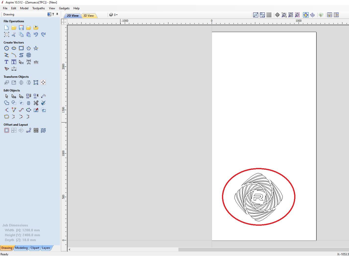
On the main workspace, we can find all the primary sections with tools for processing vectors. Starting from the top left corner, we have the menu bar with the main options and functions. On the left side, we have the sections File Operations, Create Vectors, Transform and Edit Objects, as well as Offset and Layout. With these functions, we can draw, modify, copy, cut, join, move, or rotate vectors.
In Create Vectors, we have options for drawing all types of vector shapes and text. In Transform Objects, we have tools for moving, proportionally changing dimensions, or rotating vectors. In Edit Objects, we have tools for merging and cutting vectors, changing angles, rounding edges, etc.
By clicking on the Toolpaths button in the top right corner, a new window opens containing all the functions and tools for assigning paths and the type of processing to the vectors.


To add a prepared design, go to the top left corner and click on File, then select Import, followed by the Import Vectors option. Once we have set up the workpiece, we will notice that the Import option becomes available for use.
By clicking on Import Vectors, a new window will appear where we need to select the design we want to attach to the workspace, then click Open.
Once we click the Open button, we will notice that our drawing has been transferred to the workspace, and we can start creating toolpaths for processing. To move the drawing to a different location on the workpiece, we need to select the Transform Mode option from the Edit Objects section. The Transform Mode option provides tools for moving, resizing, and rotating the selected vectors.

When we click on the Transform Mode option, all selected vectors will turn pink, with 8 points for resizing, 4 points for rotation, and a central point for repositioning.
As long as the Transform option is active, we can use these tools. Once we are done with positioning, rotating, or resizing, we need to click on the first arrow from the Edit Objects section, named Selection Mode, to exit the Transform Mode and return to the standard selection mode.


For precise dimensioning of selected vectors, we choose the Set Selected Objects Size tool from the Transform Objects section. This opens a new window where we can specify the position for anchoring the vectors during resizing in the Anchor section. Then, in the Width (X) and Height (Y) sections, we input the desired final dimensions of the vectors along the X and Y axes.


For precise positioning of vectors on the workspace, we need to choose the Move Selected Objects option from the Transform Objects section. In the X Position and Y Position fields, we enter the coordinates where we would like to move the design on the axis. In the Anchor section, we select the reference point that the drawing will be relocated according to.

Once we’ve finished positioning the drawing, we need to define the toolpaths for processing. We click the Toolpaths bar on the right side or select Toolpaths from the main menu bar in the top-left corner and choose the Show Toolpaths Tab option, which opens the desired toolbar.


From the Toolpaths menu in the Toolpath Operations section, we can find all the tools for defining toolpaths. There are several options for processing with different methods and tools. In our case, we will work with two of them: Profile Toolpath (2D Profile Toolpath) and Pocket Toolpath
The Profile Toolpath (2D Profile Toolpath) option is designed for cutting and separating material, while the Pocket Toolpath is used for defining toolpaths for engraving grooves and is an excellent method for removing large quantities of material from the piece.
When selecting the 2D Profile Toolpath option, a new window opens where several sections require input of the remaining parameters. In the Cutting Depths section, we enter the final depth we want to achieve in the Cut Depth field. In the Tool section, we select the appropriate tool for the job and adjust all of its parameters.

By clicking on the Select... button, a new window named Tool Database opens, where all the tools entered in the database are listed. In the Metric Tools subsection, we find a list of all the tools from the metric system. If the desired tool is not present in the list, we can add it by clicking the plus sign in the lower-left corner.


The newly added tool will be added to the previously selected list (Tool Type). You can now select it from the list and proceed with further setup.

After pressing the Select button, a new window named Tool Database opens, where all the tools entered into the database can be found. In the Metric Tools subsection, we have a list of all the tools from the metric system. If our tool is not in the list, we can add it by pressing the plus sign in the bottom left corner. The newly added tool will be added to the previously selected list (Tool Type).
In the Geometry section, in Units, we select millimeters, and in Diameter, we enter the diameter of the tool. In the No. Flutes section, we enter the number of flutes on the tool. In the Cutting Parameters section, in the Stepover window, we enter the value for how many millimeters the tool should overlap the previous pass. In the Feeds and Speeds section, in the Spindle Speed window, we enter the value for the spindle speed. In the Feed Rate window, we enter the value for how fast the head/tool should move while processing the material, i.e., how fast it should cut the piece. The field Pass Depth determines how deep the selected tool can enter in the material. In the Plunge Rate window, we enter how many millimeters per minute the tool will plunge into the material. The software saves all the parameters for each tool and documents them in the tool database.
To select one of the tools from the list, all we need to do is select it and click the Select button.

After selecting the desired tool, the next step is to press the Edit Passes button in the field below, labeled Passes.
In this section, we determine how many times the tool will penetrate the material along the same path to achieve the desired depth. In our case, the final depth for this operation is 3.5mm, and if we select 3 passes, the software will divide the final depth by 3, giving us a result of 1.16mm per pass (each time the tool passes along the selected vectors).
The machine will go over the selected vectors 3 times, and each time, it will progressively penetrate the material by 1.16mm.


In the Specify Pass Depths window, we can individually control each pass, meaning we can determine how deep the tool should penetrate the material with each pass. To confirm, we press the OK button.
The next function is Machine Vectors, where we have options for where exactly along the vector the tool should pass.

With the Outside / Right option, the software will generate toolpaths for the tool from the outside of the vectors. This function is used when we want to cut a piece with precisely defined dimensions.

If the tool we are cutting with has a diameter of 6mm, the software will generate the toolpath 3mm away from the outer side of the vector to achieve the exact dimensions. If we select the On (on line) option, the final piece will have dimensions of 97mm x 247mm, instead of the previously set 100mm x 250mm.

If we want to engrave or carve a design, we can select the On (on line) option, meaning that at the end of the process, the cut where the tool passed will have a width of 6mm, the same as the tool’s diameter.

The Inside/Left option allows us to carve a groove with precisely defined dimensions because the tool will move along the inner side of the vectors. The effect is illustrated in the images above.
The Ramp Effect is essential for the correct processing of the material. This effect controls how the tool enters the material. Directly plunging into the material at a 90-degree angle with an End Mill cutting tool is impractical because the lower segment, which first enters the material, does not have a cutting edge at the bottom and cannot remove the material properly.
For this reason, we use the Ramp Effect, which allows the tool to enter the material at a predetermined angle, set in the Ramp field within the Specify Ramp segment. We select Angle and enter the desired value in degrees in the adjacent field. In the Type section, we choose the method by which the tool will enter the material:
- Smooth enables linear movement during entry, - Zig Zag follows a step-like pattern, - Spiral provides a spiral entry motion.


The final step is to save the Toolpath and prepare it for export by clicking the Calculate button.

The software displays a graphical representation of the toolpaths, showing where the cutting tool will move during machining. The blue lines indicate the paths over the design (vectors), while the red lines represent the movement of the tool when it is above the material, transitioning between different vectors.
In this window (Preview Toolpaths), we have options to simulate the entire toolpath, allowing the software to generate a visual preview of both the final product and the machining process.
Once we have finished simulating the toolpaths, we need to switch back from 3D view to 2D view by clicking the 2D button located in the upper segment of the interface on the left side.

In the Toolpaths segment on the right side of the interface, we can see our Toolpath. When we select it, the entry and exit points along with the cutting direction of the tool are displayed on the design.

We have one more part of the design left to assign toolpaths to (the letter in the center of the drawing). To do this, we need to select the vectors and then, in the Toolpaths segment, choose the desired function.

From the Toolpath Operations segment, we select the Pocket Toolpath option. This function is a different operation and is not the same as the 2D Profile Toolpath.
The first operation is already completed, and the software displays it in the Toolpaths segment (in our case, it is named Profile 1). The second operation (Pocket Toolpath) will be performed with a different tool and different parameters.
This function allows us to create recesses in the material with precisely defined dimensions. In our case, we will use this function to remove material from the inside of the letter “R”, achieving an engraved effect.

As before, it is important to enter the final depth value in the Cutting Depths segment under the Cut Depth field.
From the Tools segment, we select the appropriate tool and click the Select button.
In the Passes section, we enter the appropriate number of passes, and just below, we can notice a new type of function where we define the pattern by which the tool will remove the material.
We have a choice between Offset and Raster methods.


We select Ramp Plunge Moves, set the adequate distance and click the Calculate button

As before, by clicking the Calculate button, a new window in 3D view appears, showing a graphical representation of the toolpaths for vector processing and options to simulate the process.

We can notice in the Toolpaths section that we have one more path, which is the Pocket Toolpath path that we just configured, named Pocket 1. When selected, we can see the toolpath when the tool is out of the material (marked by a red line) and the processing paths inside the letter (marked in blue).
We now need to save both generated toolpaths (Profile 1 and Pocket 1) in a .NC file so that they can be processed by the machine.
We select one of the Toolpaths and in the Toolpath Operations section, click on the last button named Save Toolpath. A new window with the same name will appear, where in the Post Processor section, we select RADEK (.nc .cnc). After selecting one of the paths, click on Save Toolpath(s).


A new window Save As will appear, where we can name our file and choose the location where it will be saved.


We repeat the same process for the second Toolpath. This completes the task of setting up the toolpaths and parameters.

Next, we need to transfer the newly generated files into the NC Studio software, through which we will execute the G-code for processing the workpiece.
The software responsible for controlling and operating the RK-609-ECO model is NC Studio. This software performs all standard operations, including parameter settings, regulating axes, spindle, and distances, and processing G-code commands and files.
After installing the software, you need to connect your personal computer to the control board, which directly communicates with the CNC drivers and controls the machine. If the control board is not attached to the computer, the software will not start.
The control board is attached to the PCI slot on the motherboard of the computer, where it is powered and facilitates communication between the computer and the machine.


After we start up NC Studio, we are greeted with the main interface of the software, where we have 4 main sections containing additional commands and options

Every time the machine is started, it is strictly necessary to perform the homing process. If this process is not executed, the machine cannot function properly, and there is a high risk of serious damage to the working elements. In order for the machine to know its position, it must touch the limit sensors located at the ends of the axes, with each axis having its own limit sensor. We will perform this process by clicking the Operation button from the main menu bar and selecting the Move to Reference Point option. In the newly opened BKREF window, click the All Axis button. This will start the homing sequence, which is necessary for the machine to function correctly. The homing process MUST be performed every time the machine is started.
To add a new file for processing, click the File window in the top-left corner and select the New and Open and Load option. After adjusting the already attached file, it is necessary to set the origin points of all the axes on the workpiece, which can be done by selecting the Jog option (active movement of the axes) in the Panel section. Setting up the origin point is carried out by clicking the w.coord. in the NC State section.


In the Panel (Manual Movement) section, there are several options for moving the axes. These allow you to control the movement of the CNC machine manually, such as:
X-axis movement: Allows you to move the machine along the X-axis. Y-axis movement: Allows you to move the machine along the Y-axis.
Z-axis movement: Allows you to move the machine along the Z-axis.
Speed control: Adjusts the speed at which the axes move.
Incremental movements: Allows you to set how far the machine moves with each command (e.g., 1mm, 0.1mm, etc.).
Jog buttons: Manual controls for moving the machine in a specific direction (left, right, up, down). These options allow for precise manual adjustments, making it possible to move the machine to specific locations or reset the position of the workpiece as needed.

The X+ and X- buttons are responsible for moving the X-axis, Y+ and Y- for the Y-axis, and Z+ and Z- for the Z-axis. To the right of these buttons are the intervals according to which the axis will move. The Jog option, when selected, enables continuous movement as long as one of the X, Y, or Z buttons is held down. The other values allow movement according to a pre-set distance. For example, if you select 5mm and click on X+, the X-axis will move exactly 5mm to the right. Rapid Movement or quick movement of the axes can be performed by holding down the Ctrl key in combination with any of the axis movement buttons.
Manually, we drive the axes to the edge of the workpiece and lower the Z-axis until the tool touches the surface of the piece and can rotate freely.
Next, in the NC State section, in the W. Coord. (Work Coordinates) window, you need to click on each field individually to zero the axes. This will reset the machine’s coordinates, ensuring that the axes are aligned correctly for the operation.

The axis is successfully zeroed when the coordinates in the W. Coord. field change to 0.000, we need to click on the field where these values are displayed.
In the adjacent sections Feedrate and Spindle rev., you can set the machine’s working speed (how fast it will cut through the workpiece) and the spindle rotation speed.

The status of the limit sensors can be viewed in the IO State window, where a red filled checkmark indicates that the sensor is properly calibrated and functioning.

Above the NC State section, there is an indicator displaying the status of the limit sensors.

To start processing the design, press the Start button in the upper section of the interface, and the machine will begin operating.

If we want to return the axis at the origin point we need to click on the “return to origin” button located right below the Operation tab from the main menu bar. After we click this button the machine starts moving towards its current origin point.
