
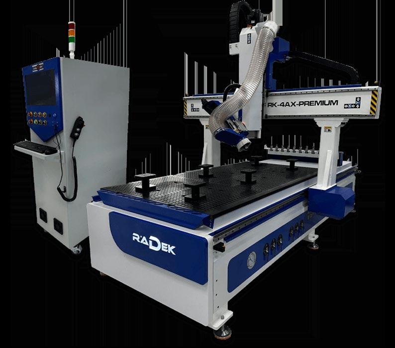


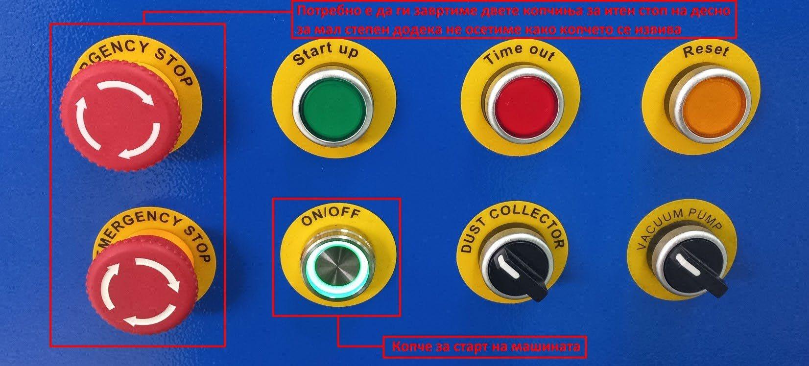
By generating the G-code, we’ve finished all the steps in Haixun Speed Design and Haixun Speed Production, and the only thing remaining is to import the code into the machine and set up all the processing parameters. The main controller is LNC, and all machine functions are operated through it. To start the machine, rotate both Emergency Stop buttons slightly to the right to restore power, then press the ON/OFF button.
As soon as the software loads up we are greeted with the main interface
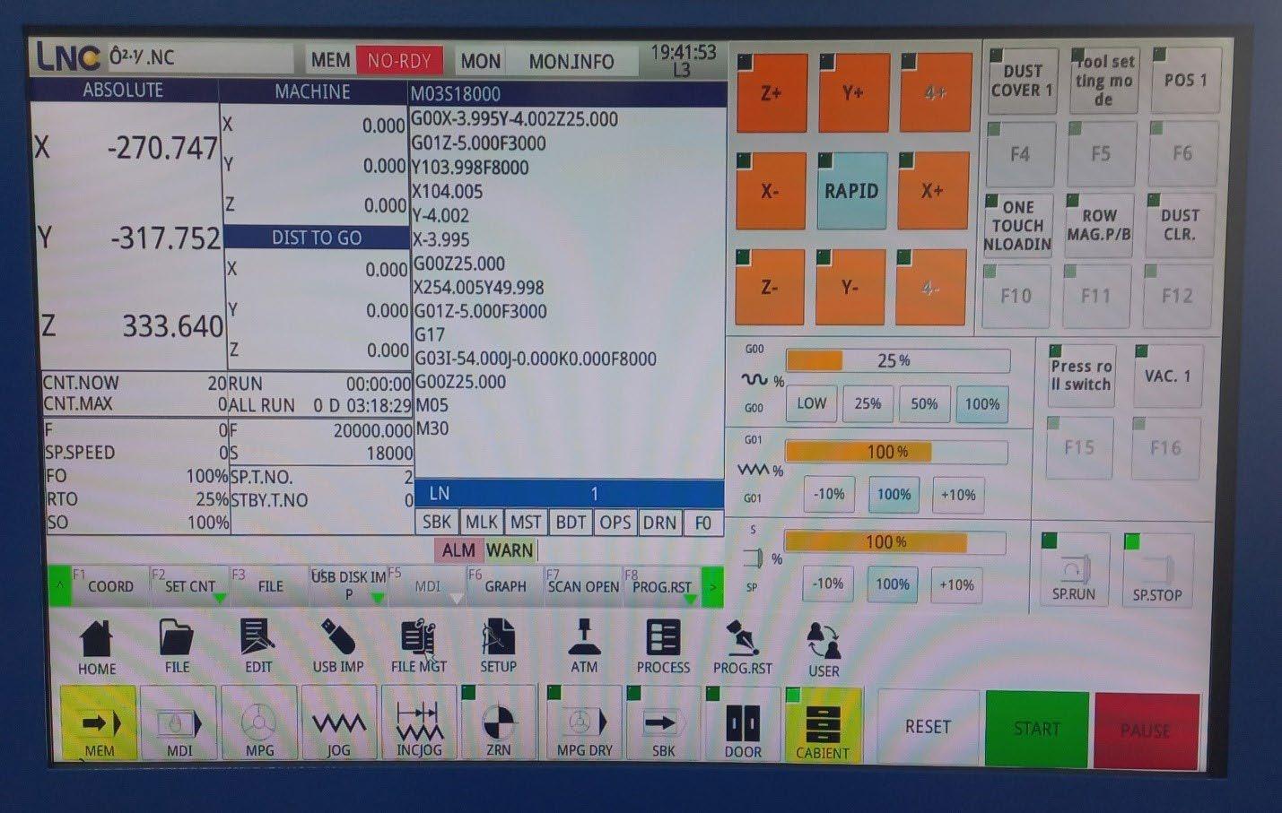
The main interface is divided in 3 sections:
Section with coordinates and G code preview
Section for control of the axis and all elements of the machine
Section with main and most frequently used tools
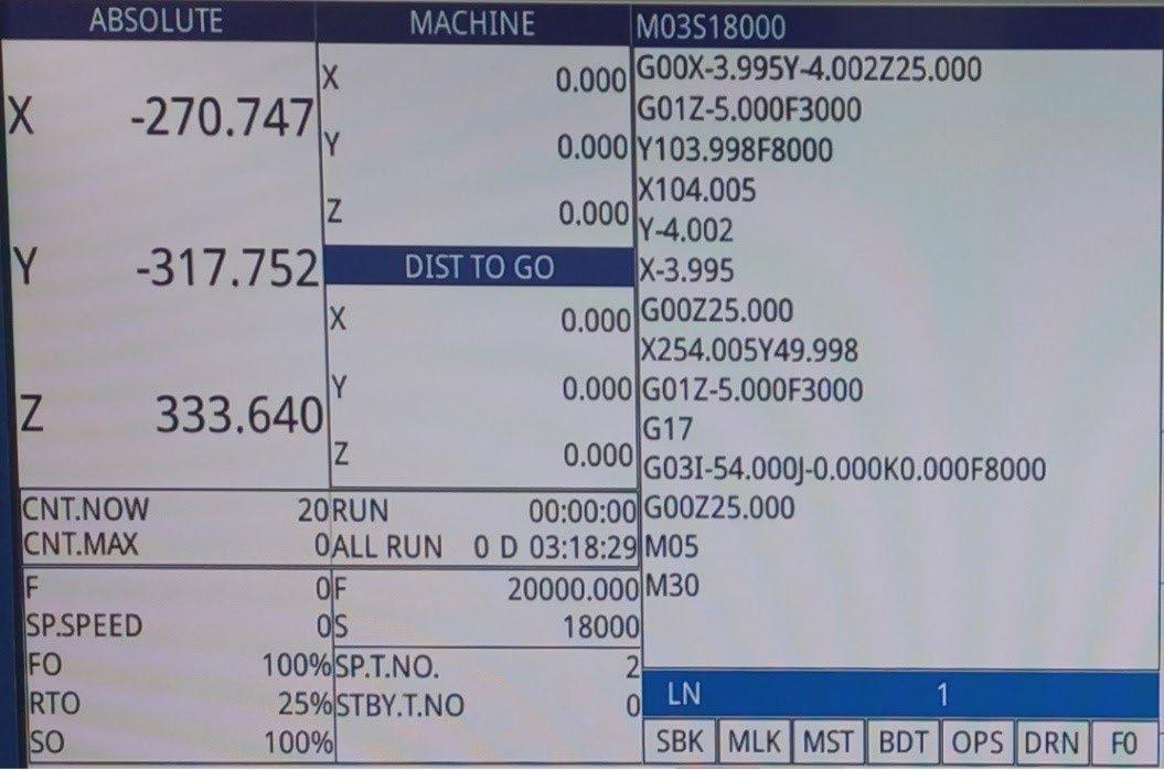
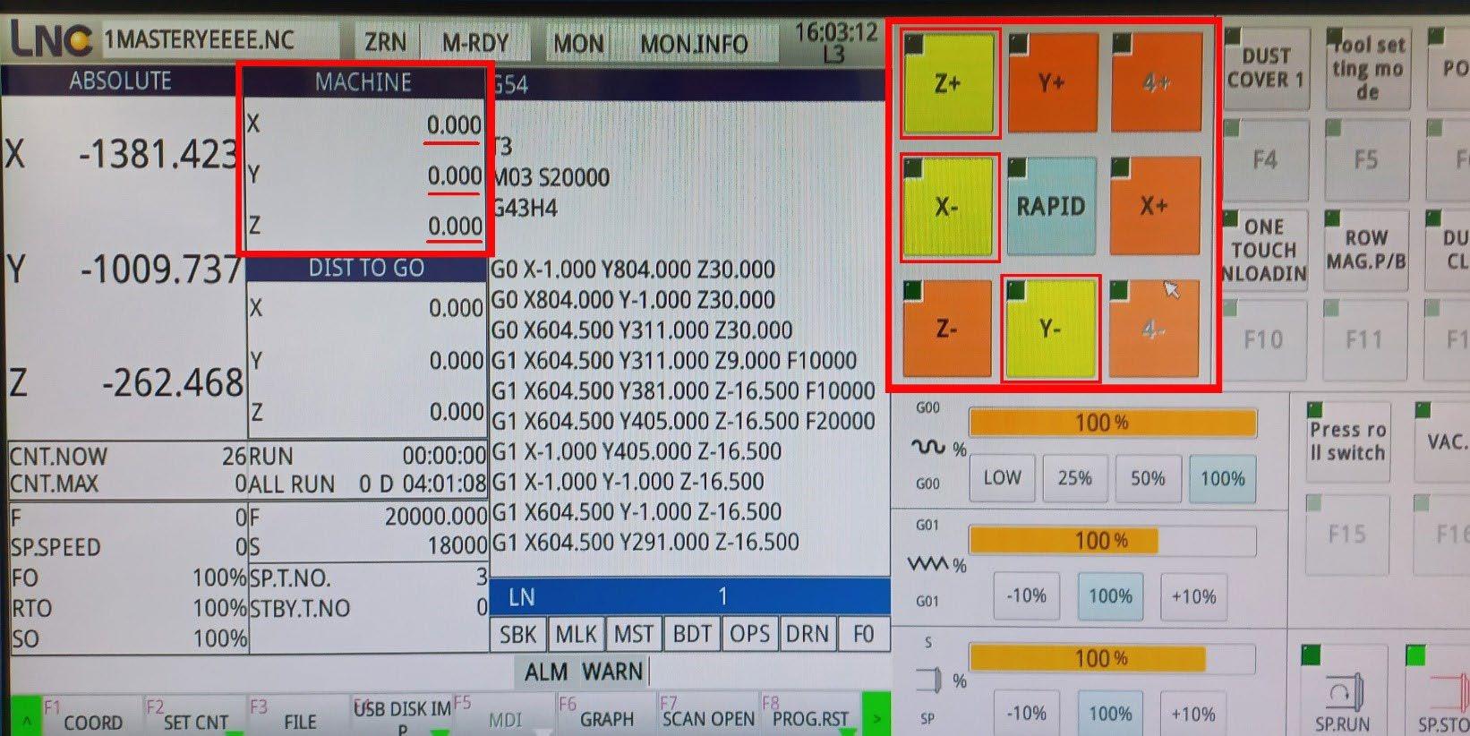
In the section for coordinates and code preview, there are several windows:
The ABSOLUTE window displays the zeroed position, i.e., the position of the axes when they are zeroed on the workpiece.
The MACHINE window shows the actual coordinates of the axes after homing the machine. (For proper operation, it is necessary to home all axes after every machine startup.)
The DIST TO GO (or Distance to Go) window shows the remaining travel distance for the axes.

The window on the far right allows us to review the entire G-code for the design. (For example, the first line M03 S18000 indicates that the M03 function will start the spindle, and S18000 shows that it will rotate at 18,000 RPM.)
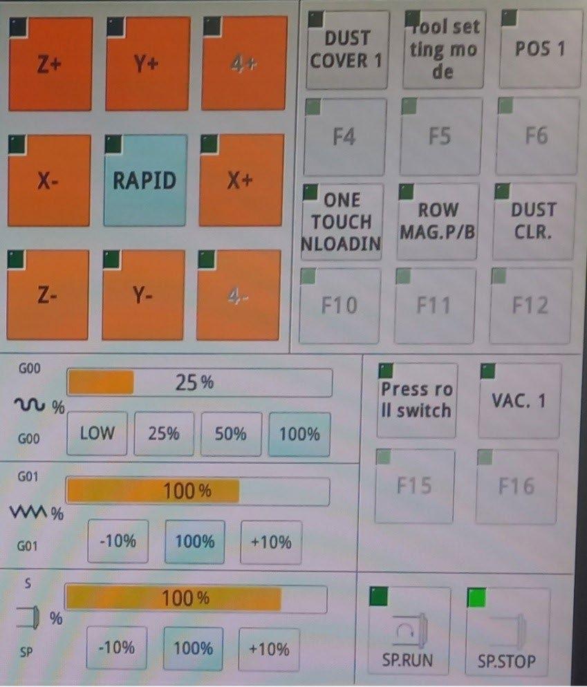
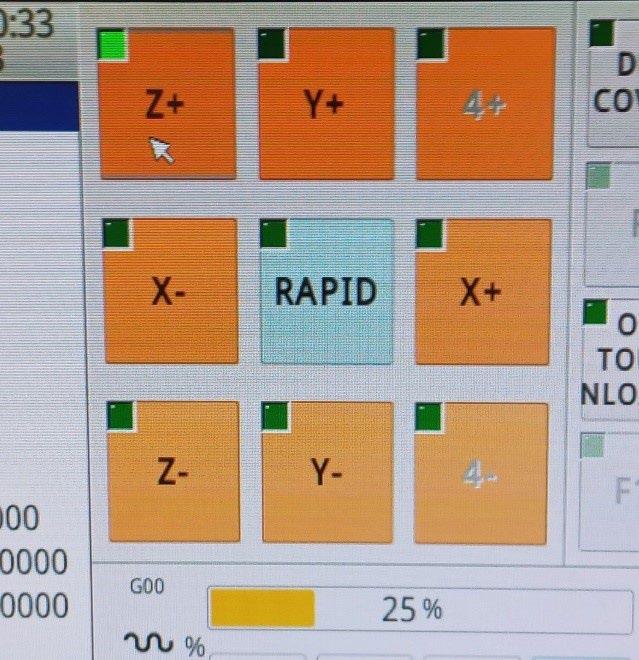
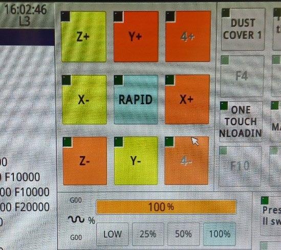
In the adjacent section, we can find all the buttons for active axis movement as well as control over all machine elements.
The orange buttons are the ones that move the axes, and they are labeled:
X+ and X- buttons move the X axis (the head) left and right Y+ and Y- buttons move the Y axis (the bridge) forward and backward
Z+ and Z- buttons move the Z axis (the spindle) up and down 4+ and 4- buttons are used to move the rotational axis if the machine has 4 axes (X, Y, Z, and rotational)
The blue RAPID button allows us to move the axes at maximum high speed! As long as it is pressed and the green triangle in its upper-left corner is lit, all the axes will move extra fast.
To move the axes, it is necessary to select one of the options JOG or INCJOG (incremental jogging). To move them using the MPG controller handle, the MPG option must be clicked.
On the right side of the orange buttons for axis movement, there is a panel with all the auxiliary elements of the machine, such as: the dust extraction system, clamping rollers, vacuum pumps, positioners, tool magazine, work surface cleaning system, and the dust cover for the spindle itself.
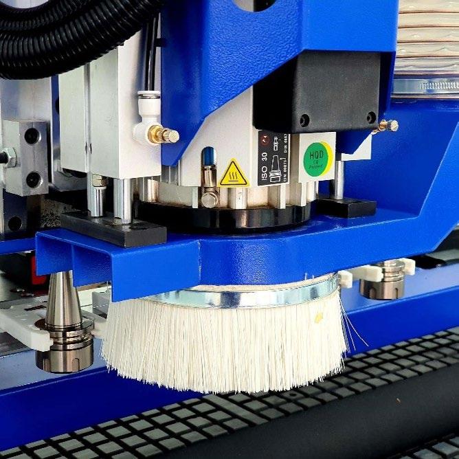
When we click the Dust Cover 1 option, a dust cover on the spindle pneumatically lifts for tool changes and lowers during operation.
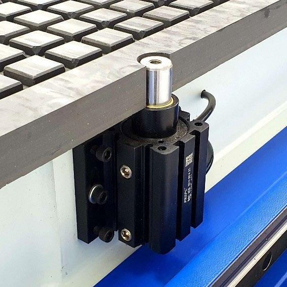
By pressing the POS1 button, we command the pneumatic positioners at the front end and left side to activate, allowing easy and efficient alignment of the workpiece on the table
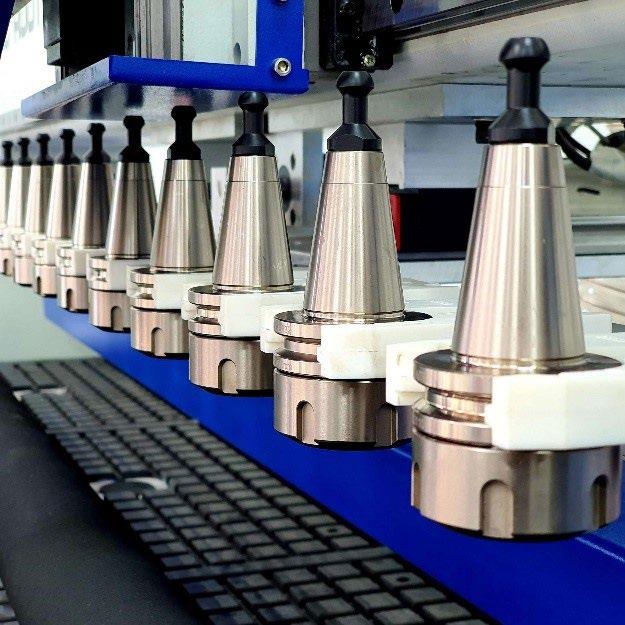
The ROW MAG. P/B button is responsible for manually moving the tool magazine forward and backward. The magazine, when in the closed position (back), is located under the bridge. It moves forward automatically only when the machine needs a tool change, or we can manually call it to change the tool order or any of the tools.
The VAC1 and VAC2 buttons are for activating the vacuum pumps. If the buttons are not pressed and do not light up yellow, we cannot start the pumps.
The SP. RUN button activates the spindle, and when its pressed the spindle starts rotating. The SP. STOP button deactivates the spindle. The bottom section contains the main tools for controlling the machine.
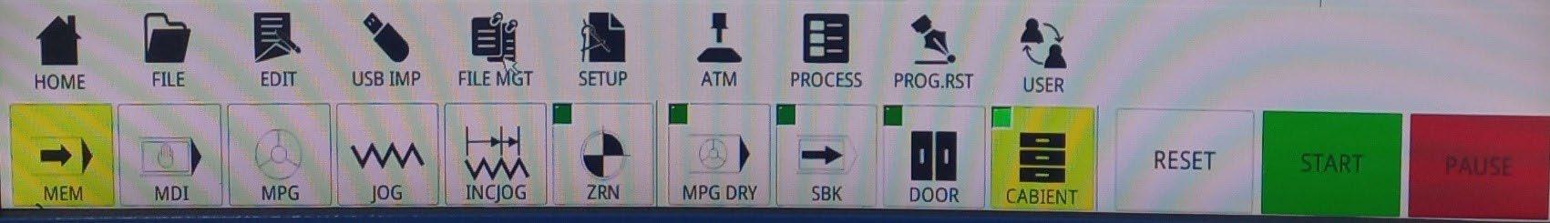
The HOME button begins the homing sequence of the machine.
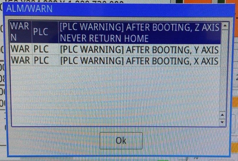
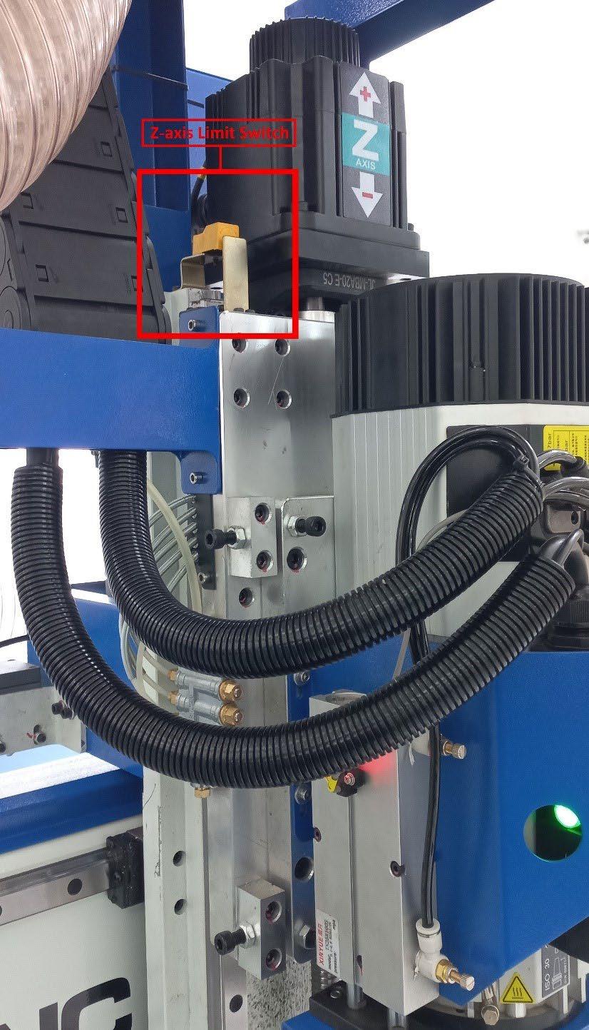
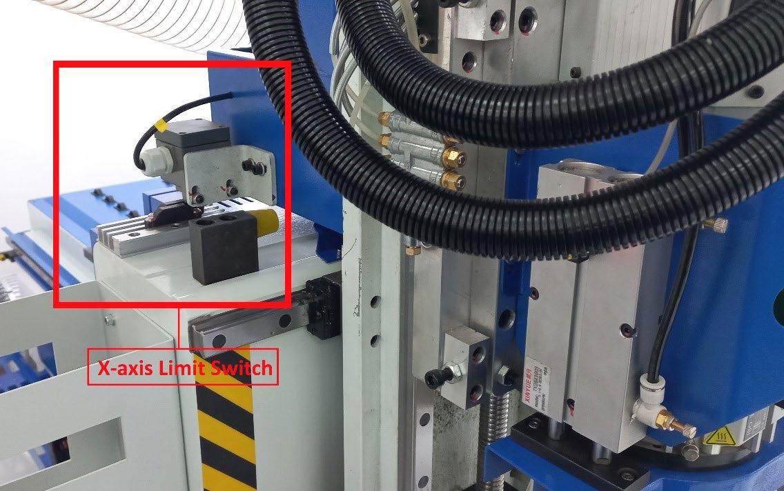
With each startup of the machine, it is necessary to perform the HOMING sequence. This process is important because the machine itself doesn’t know the position of the axes until the Limit sensors are activated. Only when the switch passes over the sensor does the machine get an understanding of where the axes are located in real space, and as long as the Homing sequence hasn’t been completed, the machine will display the alarm PLC Warning!
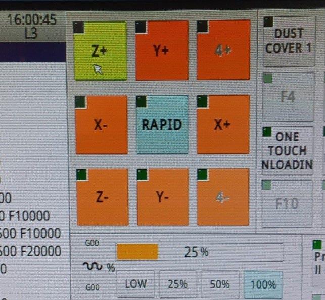
The HOMING operation is performed by clicking the ZRN button, and the first operation is to home the Z axis.
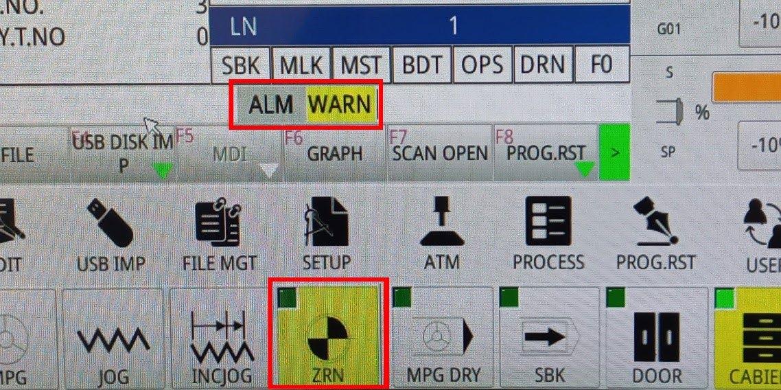
By clicking the Z+ button (while in ZRN mode), we activate the Z axis. The Z+ button lights up green in the upper-left corner, and the axis begins to move upward toward the limit sensor at a low speed. Once it makes contact, it automatically stops, moves slightly backward, and rechecks the distance to the sensor. When the sequence is complete, the Z+ button lights up yellow, indicating that the machine has homed the Z axis.
Once the Z axis is complete, we can proceed with the remaining axes (the Z axis always has priority and is homed first).
Click the X- button and wait for the head to travel to the left side of the bridge, where the limit sensor for the X axis is located. Once it makes contact, the X- button lights up, indicating that the X axis has been successfully homed.
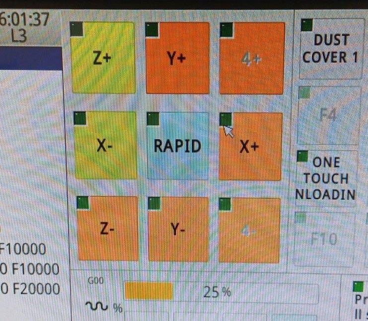
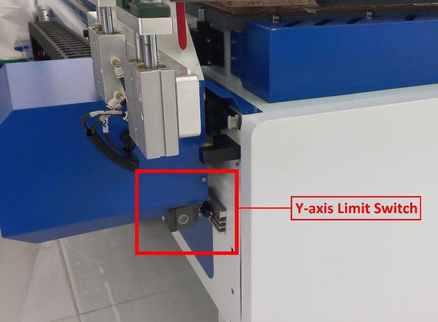
Next, click the Y- button and repeat the procedure one last time. The bridge begins to move forward toward the front of the machine, where the limit sensor for the Y axis is located. When the button lights up yellow, the Homing process is complete.
When all 3 buttons (X-, Y-, and Z+) light up yellow, the Homing sequence of the machine is complete, and we can proceed with transferring our file. An additional indicator of successful homing is the coordinate values in the Machine window, which will change to zero.
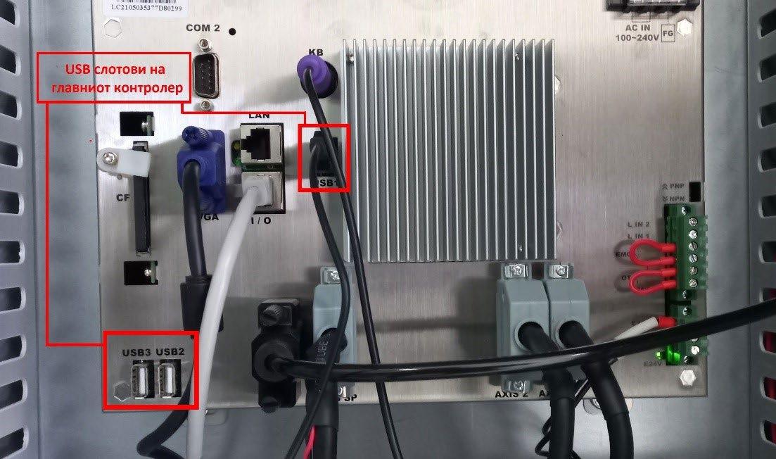
The next step is to upload our file to the controller. We need to have the file on a USB stick and connect it to one of the USB ports on the controller.
In the user interface, we search for the USB IMP (USB import) button, and by pressing it, a new window appears with two columns: on the left, a column with all the files in the machine’s internal memory, and on the right, a column with files from the connected USB stick
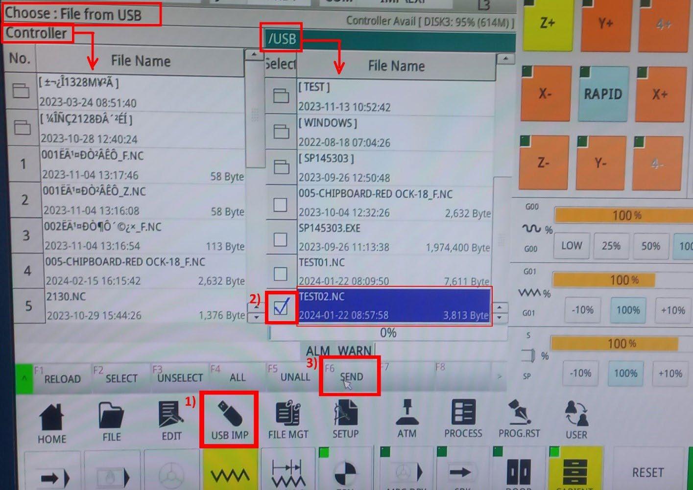
In the right column (/USB), select the file that you want to be copied to the internal memory and click SEND.
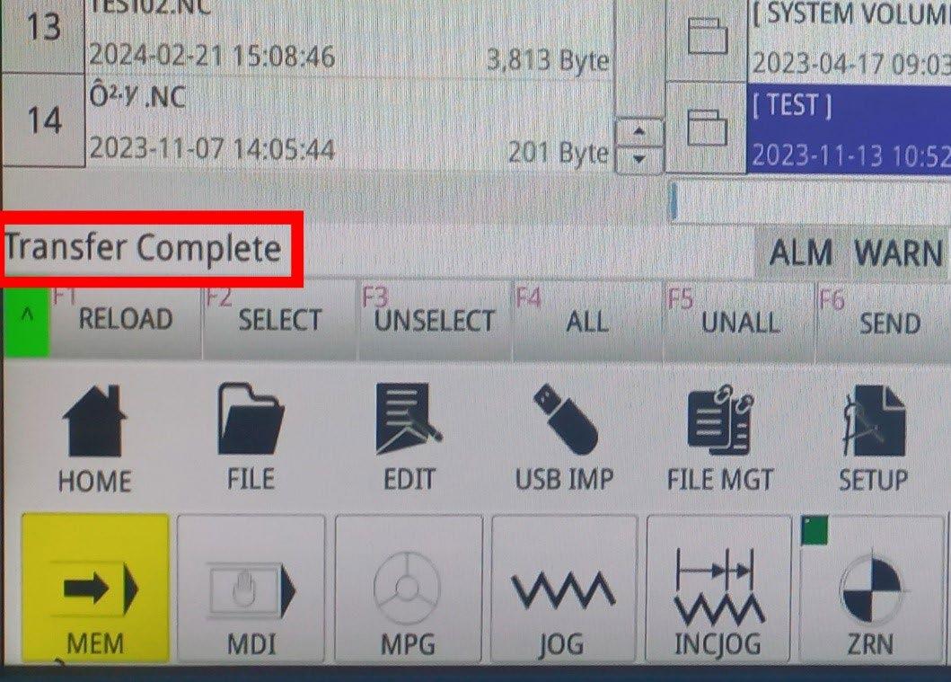
After the file is transferred, the system will display the message Transfer Complete, and then we need to select the transferred file from the internal memory
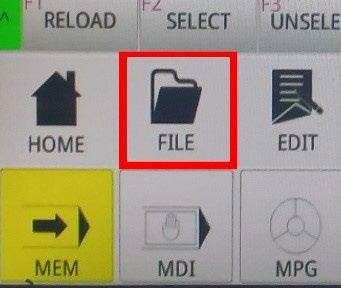
By pressing the FILE button, a new window opens, displaying all the files transferred to the machine’s internal memory. Find the desired file in the list, select it, and click OK
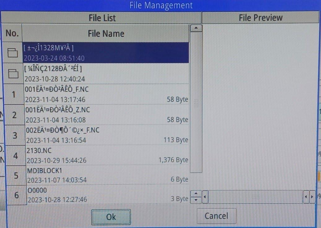
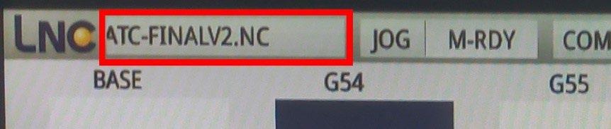
An additional indicator of a successful Upload & Load can be found in the upper-left corner of the interface, where the name of the file will be displayed in the window
In the File Preview section, we can check the G-code, and if we want to make any changes to it, we will do so using another option located in Edit.
The window has two sections: on the left side, there is a column where the G-code of our file is located, and on the right side, there is a graphical representation of the code.
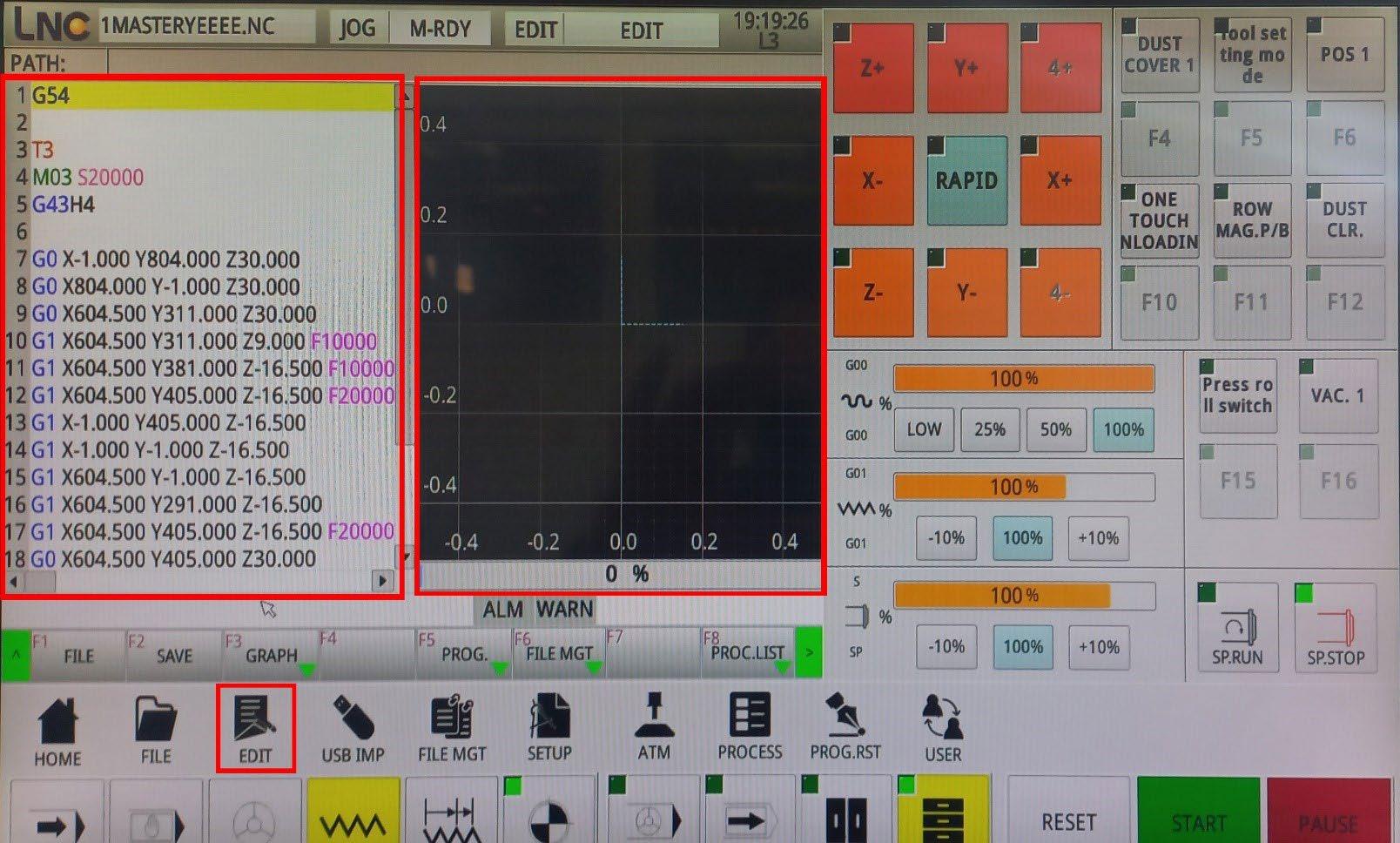
After making any changes, it is necessary to save the modification by pressing the SAVE button.
If we want to transfer a file from the machine to the USB, rename a file, or delete it, we click the FILE MGT button, and a section will appear where, on the left side, we have a list of files from the internal memory, and on the right side, there is a window where we can preview the selected file.
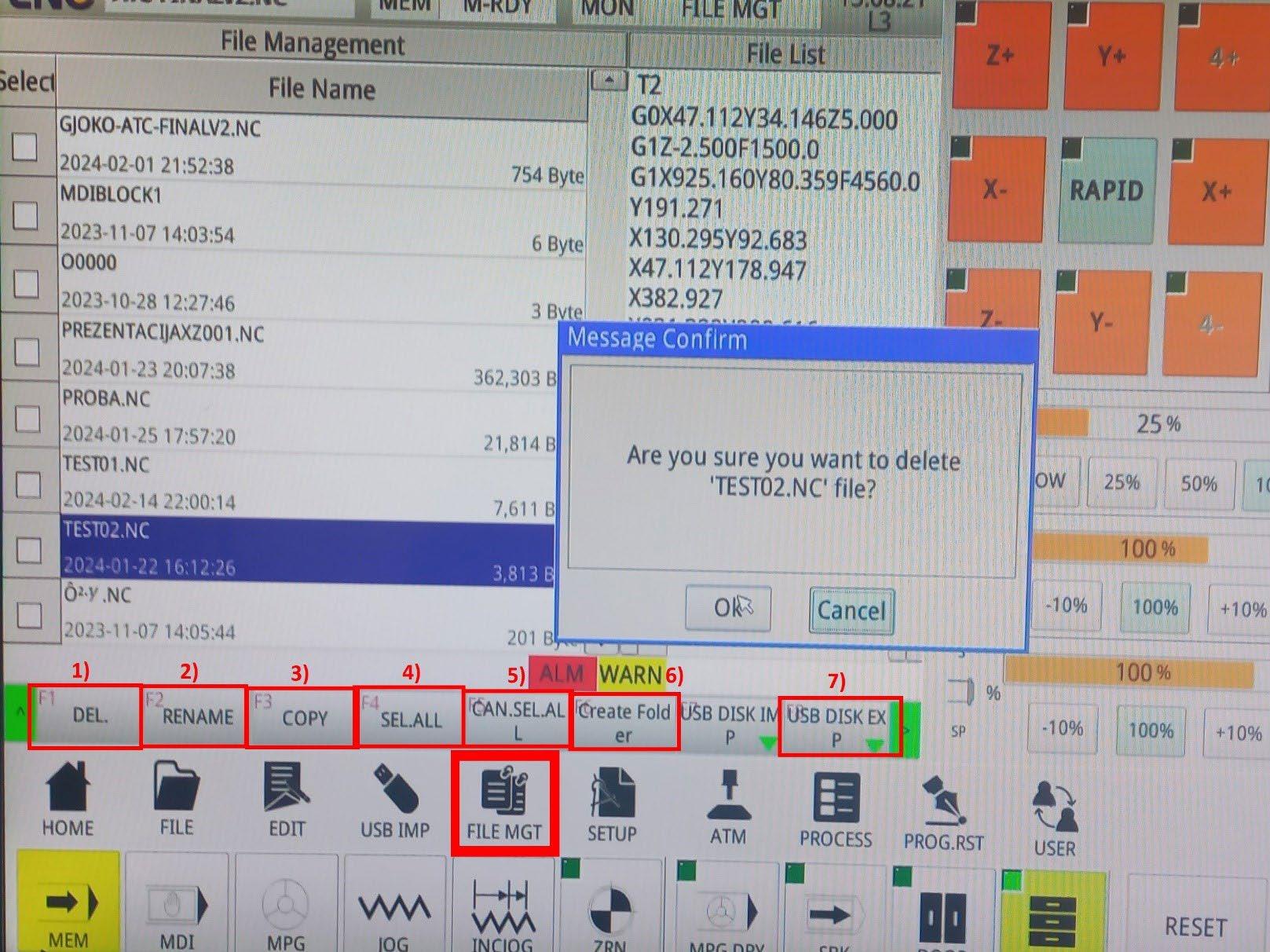
1. The DEL (delete) button allows us to delete the selected file.
2. With the RENAME button, we can rename the files.
3. The COPY button copies the selected file.
4. The SEL.ALL (select all) button selects all files in the list.
5. With the CAN.SEL.ALL button, we deselect the files.
6. The Create Folder button creates a new folder.
7. With the USB DISK EXP (USB disk export) option, we can transfer a file from the internal memory to the USB disk.
The next step is to position the workpiece on the table, and we can start with adding the origin points (zeroing the machine) and preparation for machining. By clicking the POS 1 button, we activate the positioners on the worktable and, with their help, align the workpiece. Once we ensure that the plate is correctly positioned, we deactivate the positioners and click Home, then JOG, to move the axes to the desired position on the workpiece and reset them.
After positioning the axes on the workpiece, we need to enter the SETUP menu where we will reset the X and Y axes.
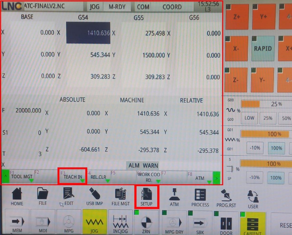
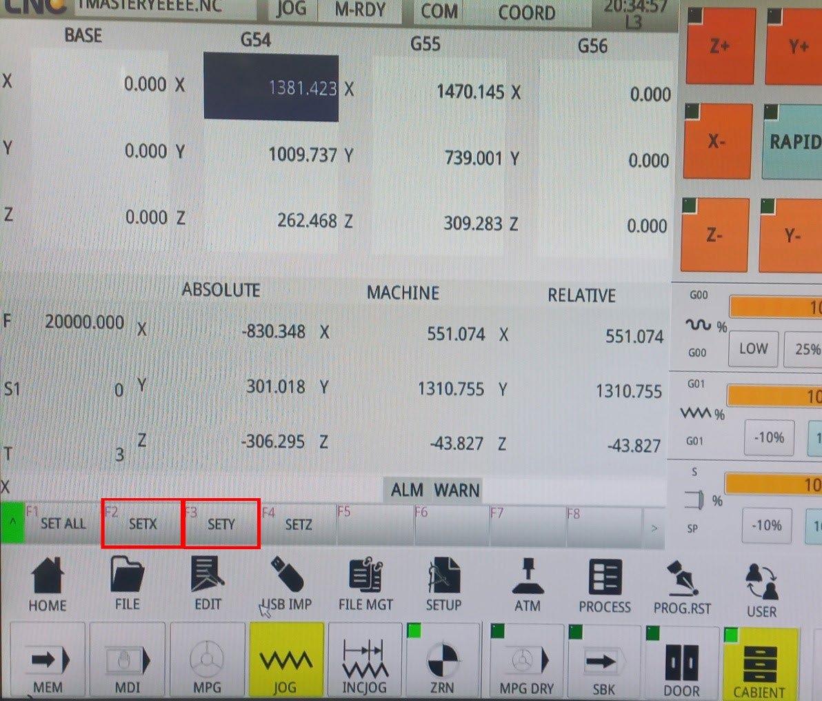
Once we ensure that the X and Y axes are in the correct position, we click the TEACH IN button, and a new section will open where we need to click SETX and SETY
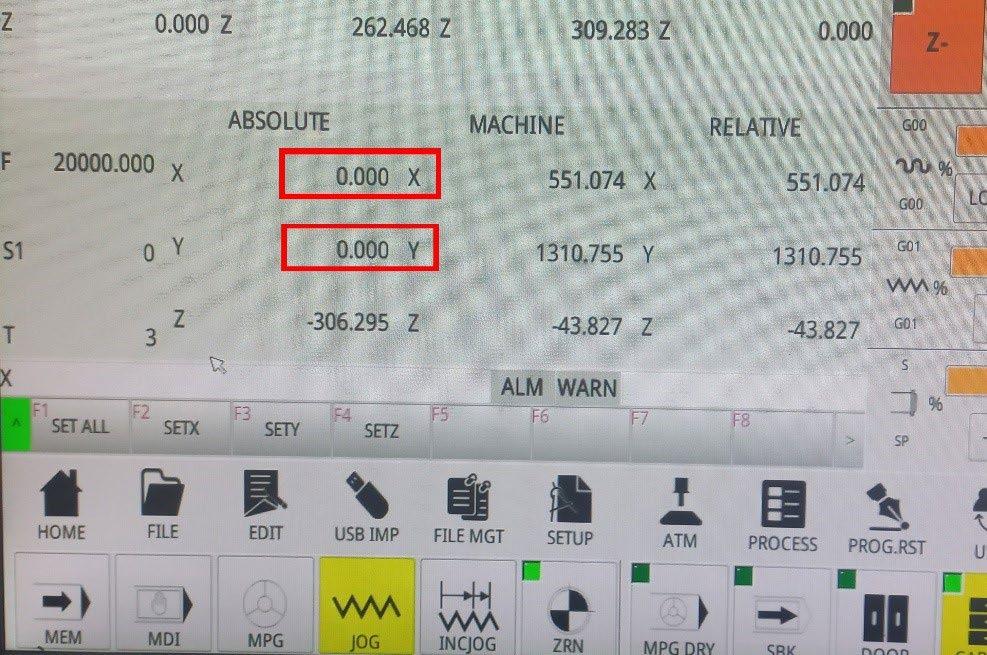
The main indicator for zeroed axes is the coordinate values in the ABSOLUTE table, where the zeroed axes will have new coordinates of 0.000.
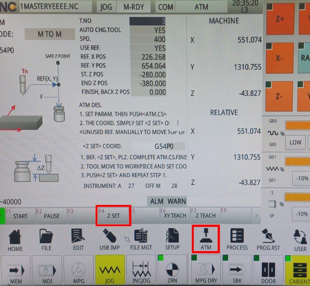
We may notice that the Z axis still has the original coordinates, and this is because it has not yet been zeroed. This can be done by pressing the ATM button, and in the newly opened window, click the Z SET option.
A crucial point when zeroing the Z axis is to start the vacuum pumps before zeroing, as the vacuum itself pulls the workpieces towards the table by 2-3mm. The tip of the tool, during the zeroing process, should gently touch the surface of the plate and rotate freely. Those 2-3mm can play a significant role in the final product.
We can check if the axis has been zeroed in the ABSOLUTE table, where the coordinates for Z should be 0.000.
Once we ensure that all the axes are zeroed in the desired position, we can start processing the workpiece.
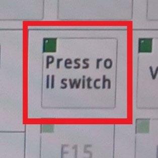
We press the PRESS ROLL SWITCH button to lower the rollers onto the workpiece and turn the DUST COLLECTOR knob to the right to start the dust extraction.

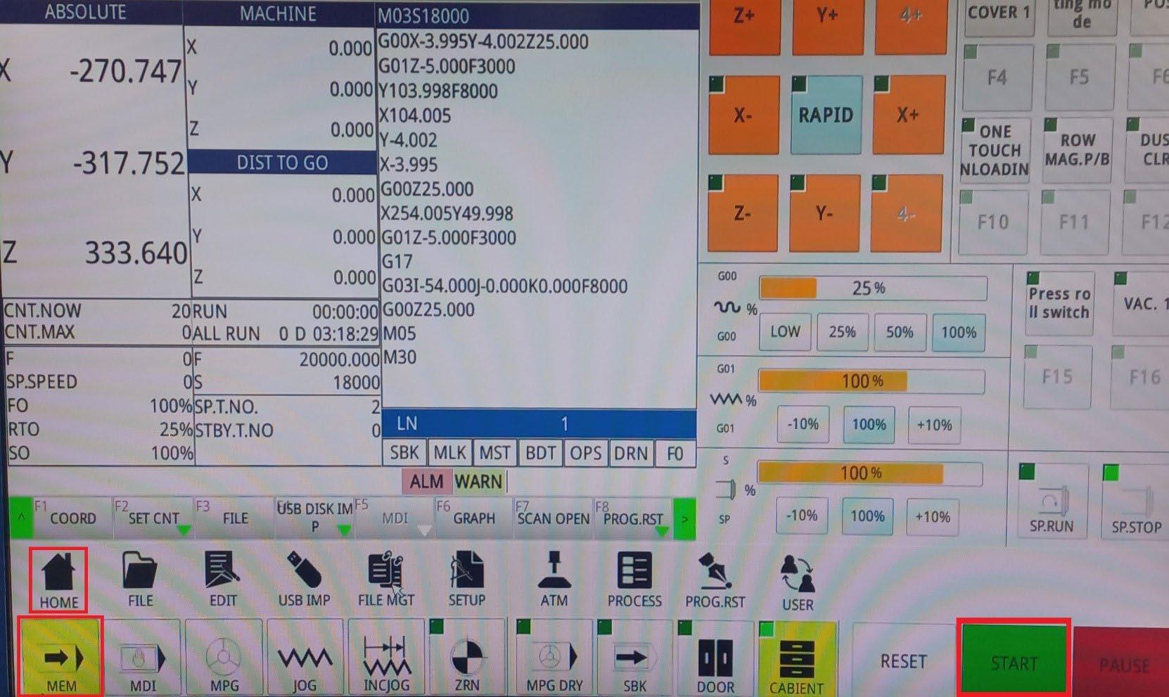
On the controller, we click MEM and then the START button. This executes the G code and the machine begins the processing.
It is recommended to be present next to the machine cabinet during processing in case it is necessary to press the emergency stop.