
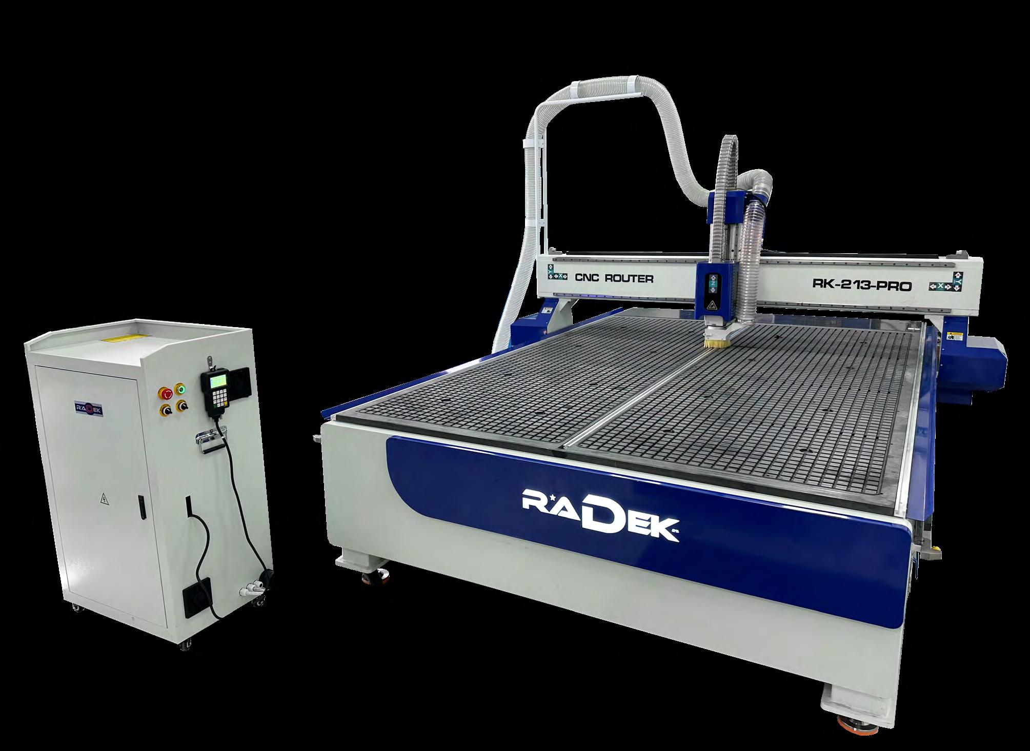


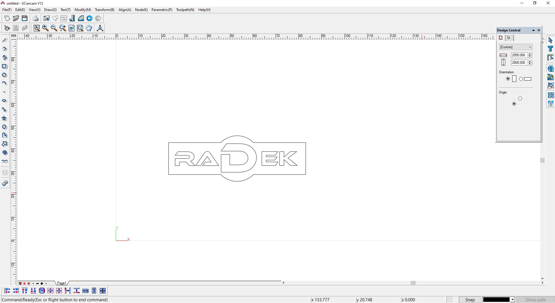
Ucancam
To begin creating our design, we need to assign paths and processing methods to the vectors in the drawing.This process is carried out using the Ucancam software. In Ucancam, we import the previously prepared drawing and define all processing parameters, such as:
The thickness and dimensions of the workpiece
The size, dimensions, and specifications of the cutting tool
The final depth and processing pattern
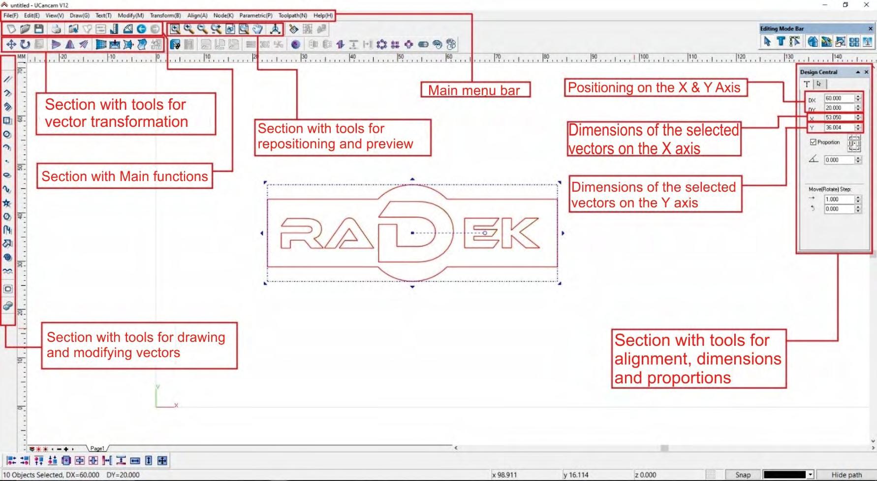
Once we launch the program, we are greeted by the Ucancam interface, where we can identify key tool sections, including:
The main menu bar, located at the top left
The toolbar below it, which contains various functions and operations
The left-side panel, featuring commonly used tools for shapes and vectors
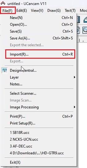
To upload the desired drawing, go to the main menu bar, select File, and then click Import.

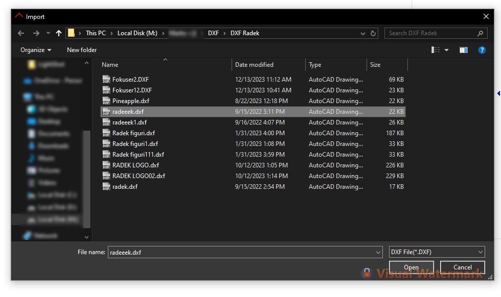
Clicking the Import button opens a new window titled Import, where you need to locate the desired DXF file. To upload it, simply select the file and click Open.
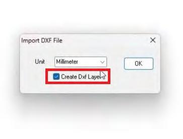
After clicking Open, a small new window titled Import DXF File appears. Here, you need to uncheck the Create DXF Layer option and press OK.
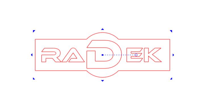
Clicking the OK button generates a frame around the imported design, visually representing the space it will occupy and its placement on the workpiece. To finalize the position, adjust the frame as needed and left-click once it is in the desired location.
Once the vectors are imported onto the workspace, the next step is to assign further processing parameters.
To do this, first select the vectors to which you will assign toolpaths, then click on the Toolpath segment in the main menu bar. This will open a window with various tools and functions, from which you select the Profile Machining option.
Each selected vector changes to red and shows blue indicators in each corner to adjust proportions. There is also an indicator for rotating the vectors freely and a central point for repositioning them.

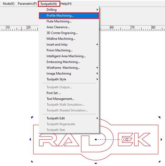
By clicking on the Profile Machining option, a new window with the same name opens, where we can adjust the mandatory processing parameters based on the requirements.
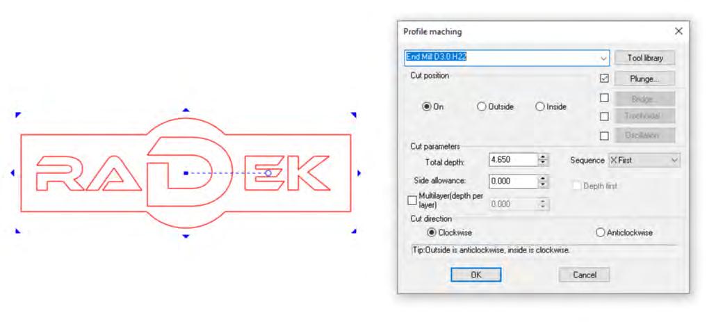
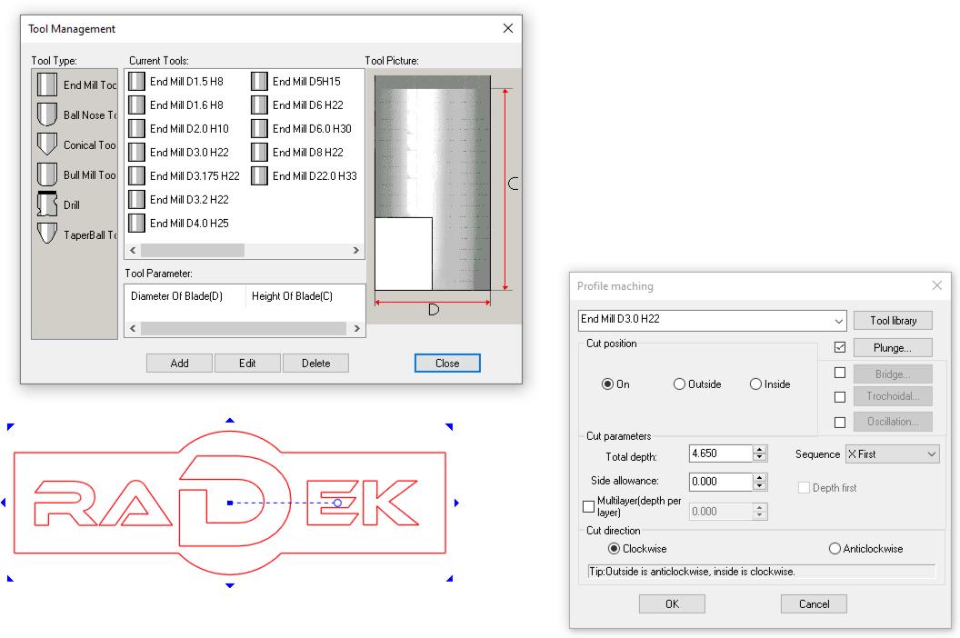
The first step is to select the appropriate tool from the tool database. This is done by clicking the topleft field next to the Tool Library button, which opens a menu/list of different tool types. If the desired tool is not found in the list, we can click on the Tool Library button again to access the Tool Management window, where we will find a detailed list of tools from the database. In the Tool Type section, all the groups and types of tools are listed. By selecting a type in the adjacent Current Tools window, a list of all tools of that type in the database appears. In the Tool Picture section, a graphical representation of the selected tool is shown.
To select a tool, we click on it twice in the Current Tools section. To modify the characteristics of the selected tool, we click on Edit, and to add a new tool to the existing list, we click on Add.
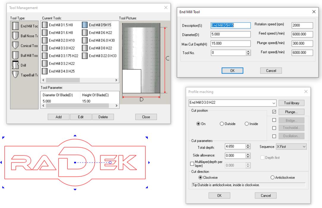
In the newly opened window, we enter the necessary parameters, such as:
Description: The description/name of the tool.
Diameter: The tool’s diameter.
Max. Cut Depth: The maximum depth the tool can penetrate into the material.
Tool No.: The tool number (useful when using an automatic tool changer system).
Rotation Speed: The tool’s rotations per minute.
Feed Speed: The speed at which the machine will process the material (how fast the tool will cut).
Plunge Speed: The speed at which the tool will penetrate the material.
Fast Speed: The axis movement speed when the tool is not in contact with the material.
Once we set up the cutting tool, we need to select the toolpath from the lower section, named Cut Position. This determines whether the tool will travel directly along the lines of the drawing, or from the outer or inner side of the lines.
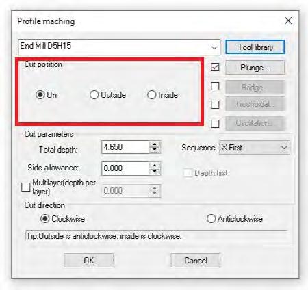
The On option (along the line) is useful when engraving on the surface of the material.
The Outside option (outside the line) is ideal when cutting a piece to precise dimensions. The software will account for the tool’s thickness and position the tool outside the line by half the diameter of the cutting tool.
The Inside option (inside the line) is used when hollowing out a section with exact dimensions. In this case, the software will consider the tool’s thickness and cut along the inside of the line by half the tool’s diameter, ensuring accurate dimensions.
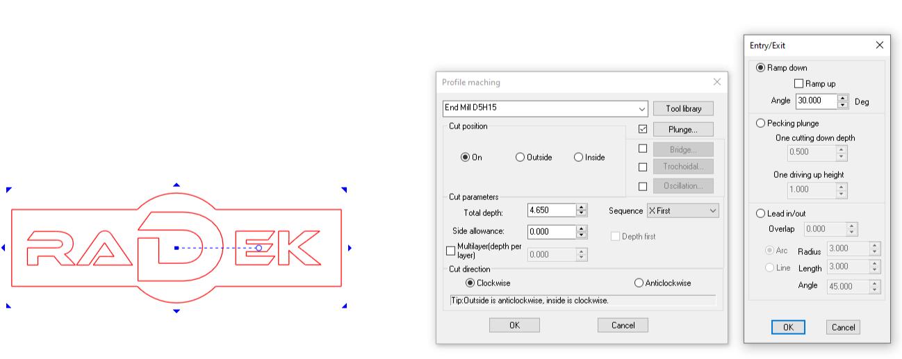
The next setting option is Plunge, which determines how the tool enters the material. There are three available methods: Ramp Effect, Pecking Plunge, and Lead In/Out. The Ramp Effect sets the angle at which the tool enters the material, resulting in a diagonal movement. Pecking Plunge controls how many small incremental steps the tool takes to penetrate the material at the same point.
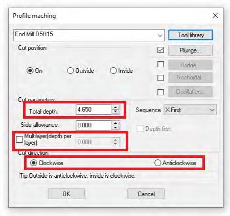
In the Cut Parameters section, the Total Depth field is used to enter the final depth the tool should reach.
In the Multilayer section, we specify the depth increment per pass that the machine will use to achieve the final depth. For example, if the final depth is 20mm and we set 4mm in the Multilayer field, the machine will repeat the same movements over the same design five times to reach the total depth of 20mm.
In the Cut Direction section, we select the direction in which the tool/spindle rotates.

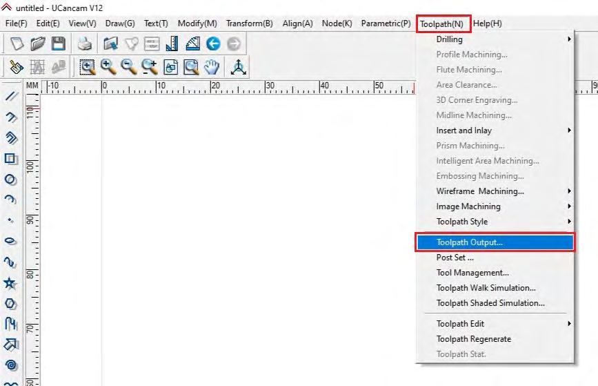
Once all parameters are set, we click the OK button and notice that the vectors change color from red to blue. All blue vectors have assigned toolpaths for processing. The next step is to save the toolpaths as an NC file.
To do this, we select all toolpaths and, in the Toolpath menu, choose the Toolpath Output option.
With the Toolpath Output option, we configure the Origin Point (starting position) and the Safe Z Height (the safe lifting height for the Z-axis). We then process the toolpaths using the desired processor and save them in the required file format (.NC file in our case). Area Clearance
The Area Clearance option is used to process all designs where we want the machine to remove material inside the selected vectors. For example, we can carve out a section of the material in a circular, square, or any other recessed shape with a specific depth. The carved area will have the exact shape of the selected vector, while the depth is defined manually. To access this option, we select the desired vectors, open the Toolpath menu from the main menu bar, and choose Area Clearance.
A new window named Area Clearance will appear, containing the main processing parameters.
In the first field, we select the appropriate tool from the Tool Library. In the Machining Strategies field, we can choose between two options: Raster and Offset.With the Raster option, the tool processes the material axis by axis. It first moves along the X-axis and, at the end of the toolpath, shifts along the Y-axis before continuing again along the X-axis.
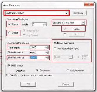
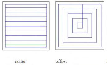
With the Offset option, the toolpaths are generated in a way that starts from the center of the machining area and progressively move outward in concentric circles until reaching the edge of the vector.
In the adjacent field, we notice the Sequence option, which is responsible for setting the processing sequence/order. We have several options to choose from: Layer First, Depth First, X First, Y First, and Near First.
With the Layer First option, the first step for the tool is to complete the first layer of all selected vectors, continuing with the same approach until all layers are processed.
With Depth First, the toolpaths are generated so that the tool achieves the final specified depth for a given vector before moving on to the next, processing each vector to its final depth before continuing to the next point/vector.
With X First, the machine processes the vectors along the X-axis first. The same applies to Y First, where the machine processes vectors along the Y-axis first.
With Near First, the machine orders the processing based on the proximity of the vectors in the drawing. After completing the first vector, it selects the nearest one for the next processing step.
The Ramp option allows us to determine how the tool will enter the material, either by moving in a zigzag pattern or by entering with a helical motion (drawing circles stacked one over the other, similar to a classic spring structure).
In the Machining Parameters section, we set the final desired depth in the Total Depth field.
In the Overlap Ratio option, we enter a value to determine the percentage overlap of the toolpaths during processing. This ensures that the surface is processed smoothly and evenly.
With the Multilayer Machining option, we define how many passes the machine will take to reach the final depth. For example, if the final depth is 20mm, we can set the machine to progressively enter the material by 4mm per pass. This means the final depth will be achieved in 5 passes, with the tool going 4mm deeper into the material each time.
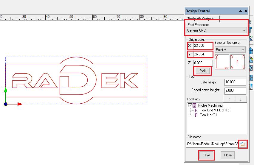
We need to ensure that the vectors and generated toolpaths are selected before choosing the Toolpath Output option.
In the newly opened window, we enter the coordinates for the starting position in the respective fields and click Pick. In the Post Processor window, we select the appropriate process. Then, in the File Name field, we enter a name for the file and click the Save button.
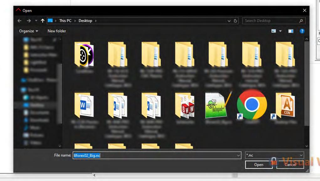
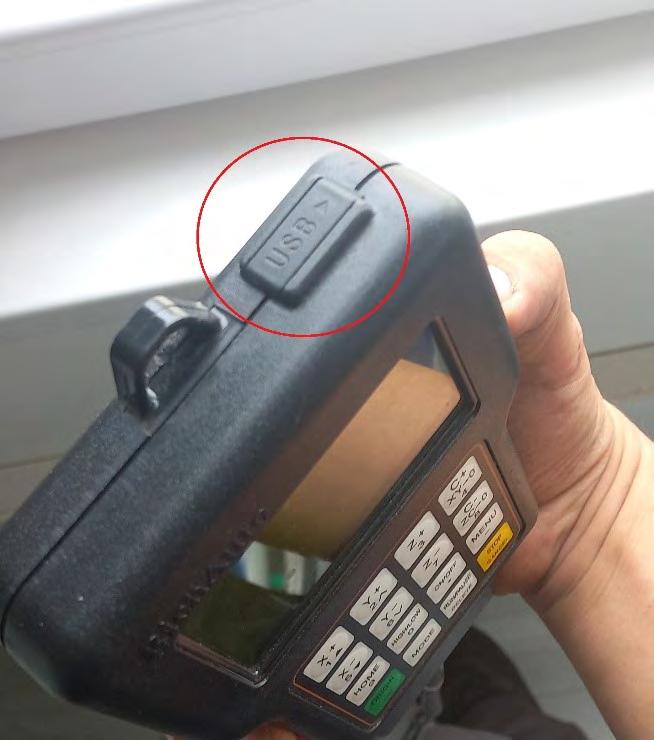
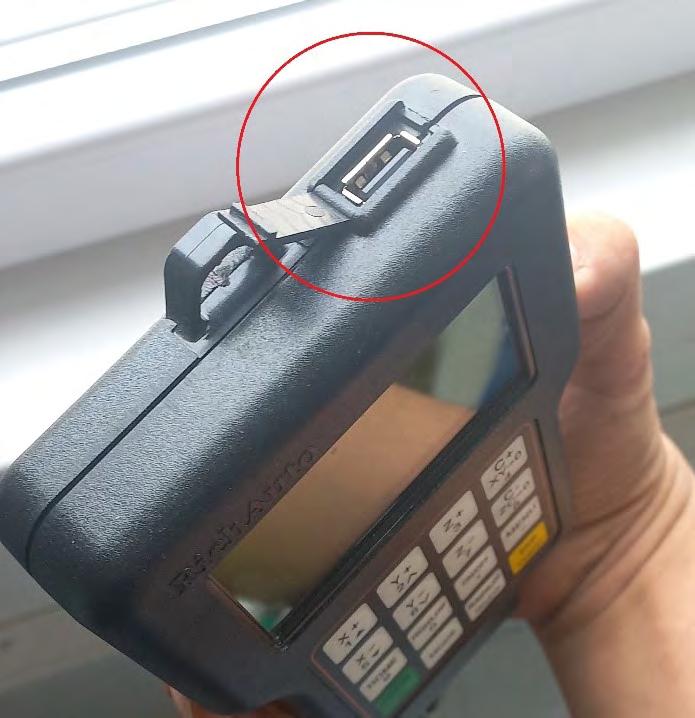
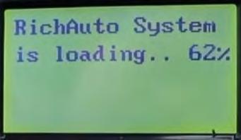
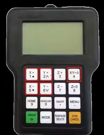
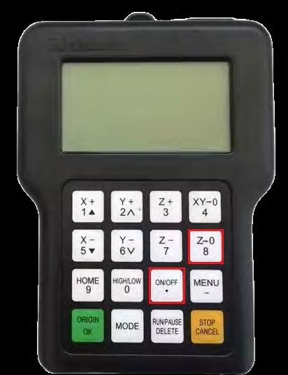
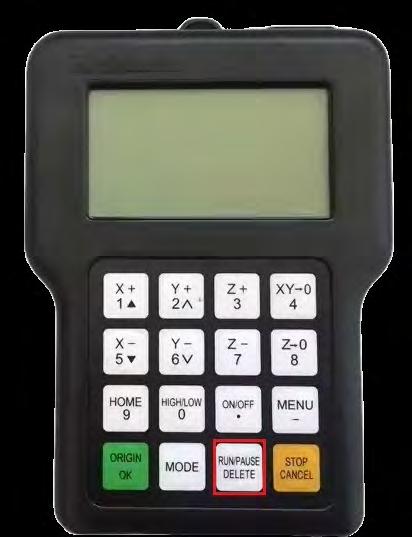
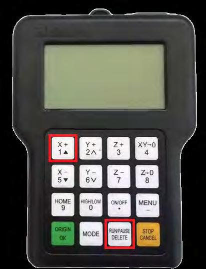
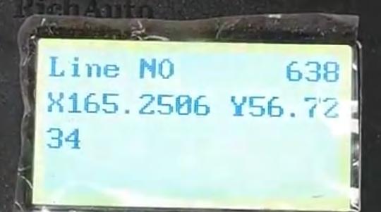
With this procedure, we have completed the generation of the G-code with the toolpaths. The next step is to transfer the file to a USB stick and insert it into the slot of the RichAuto pendant, the controller responsible for executing the G-code files and controlling the machine during operation.