


The software responsible for creating toolpaths and transforming vectors is called Vectric Aspire. Every drawing or design consists of lines (Vectors) to which we need to assign toolpaths with the appropriate parameters.
To begin, we launch the Aspire software, which presents us with the main workspace, where several options are available.

To start a new file, where we will define all the necessary parameters, we click on “Create a new file.” To open an existing file, we select “Open an existing file.”
The same function can be performed by clicking on “File” in the menu bar and then selecting “New” to create a new file or “Open” to open an existing one.
You may notice that the “Import” option is inactive. This is because newly created or existing designs require a workspace to be attached to. To enable importing, we first need to create a new file.

After clicking on “Create a new file,” we are presented with a new workspace, where we need to define the length, width, and height of the workpiece. These options can be found in the Job Setup section.

In the Job Setup section, we have options for configuring the workpiece, its processing method, and its dimensions.
Job Type Subsection
This subsection provides options for setting up how the workpiece will be processed:
Single Sided – The most commonly used option, selected when machining will be done on only one side of the material.
Double Sided – Used when both the top and bottom of the workpiece need to be machined. The workpiece must be flipped after completing one side.
Rotary – Used for rotary axis machining, suitable for cylindrical or spherical workpieces.
Job Size Subsection
Here, we input the dimensions of the workpiece:
Width (X) – The width of the material.
Height (Y) – The length of the material.
Thickness (Z) – The thickness/height of the material. We also set the units to mm.
Z Zero Position Subsection: This defines the surface used to zero the Z-axis where we have two options:
*Machine Bed *Material Surface
We select Material Surface, which tells the software that the Z-axis will be zeroed on the top surface of the workpiece.
XY Datum Position Subsection


This determines the zeroing point for the X and Y axes. It is important to match the zeroing points in Aspire with the physical origin points set on the machine.
If we select the Double Sided option for two-sided machining, several additional options become available.
In the Z Zero Position subsection, we must choose a zeroing point for both surfaces of the workpiece. In the Flip Direction Between Sides subsection, we select the rotation orientation for flipping the workpiece when switching sides.

After setting all the parameters for the workpiece, we press the OK button, which takes us to a new workspace.

On the main workspace, we can find all the key sections with tools for vector processing. Starting from the top left corner, we have the menu bar with the main options and functions. On the left side, we find the sections: File Operations, Create Vectors, Transform Objects, Edit Objects, Offset and Layout. These functions allow us to draw, modify, copy, trim, merge, move, or rotate vectors. In Create Vectors, we have tools for drawing various vector shapes and text. In Transform Objects, we find tools for moving, proportionally resizing, or rotating vectors. In Edit Objects, we have tools for joining and trimming vectors, modifying angles, rounding corners, etc. By clicking the Toolpaths button in the top right corner, a new window opens, containing all the functions and tools for assigning machining paths and selecting the processing type for vectors.


To add a prepared drawing, go to the top left corner, click on File, then Import, and select Import Vectors.
We can notice that after setting up the workpiece, the Import option is now available for use. By clicking Import Vectors, a new window appears where we need to select the drawing we want to upload to the workspace and then press Open.

After clicking the Open button, we can see that our drawing has been transferred to the workspace, and we can begin creating toolpaths.
To move the drawing to a different location on the workpiece, we need to select the Transform Mode option from the Edit Objects section.
The Transform Mode option allows us to move, resize, and rotate the selected vectors.
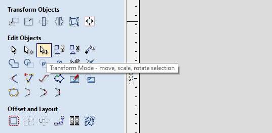
When we click on the Transform Mode option, all selected vectors turn pink and gain: 8 points for resizing, 4 points for rotation, and 1 central point for repositioning.
As long as Transform Mode is active, we can use these tools. Once we finish positioning, rotating, or resizing, we need to click on the first arrow in the Edit Objects section, named Selection Mode, to exit Transform Mode and return to the normal selection mode.


For precise dimensioning of the selected vectors, we select the Set Selected Objects Size tool from the Transform Objects section. This opens a new window Where In the Anchor section, we choose the position to anchor the vectors during resizing (either from the center, corner, or side).
In the Width (X) and Height (Y) sections, we enter the desired final dimensions for the vectors along the X and Y axes.This tool allows for precise control over the scaling of the selected vectors.


For precise positioning of the vectors on the workspace, we need to select the Move Selected Objects option from the Transform Objects section.
In the X Position and Y Position fields, we enter the values where we want the design to be moved along the coordinate axes. In the Anchor section, we choose the reference point from which the drawing will be relocated. This ensures that the movement is relative to the selected anchor point, allowing for precise placement on the workspace.

Once we have finished positioning the drawing, we need to define the machining toolpaths.
We click on the Toolpaths bar on the right side or select Toolpaths from the main menu bar in the upper left corner. Then, we choose the Show Toolpaths Tab option, which opens the desired toolbar.
This toolbar contains all the necessary functions for creating and managing machining toolpaths.


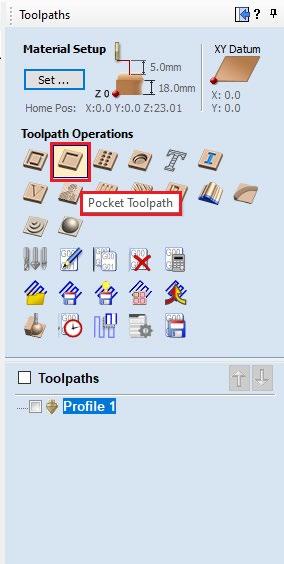
From the Toolpaths menu, in the Toolpath Operations section, we can find all the tools for defining machining toolpaths. There are various processing options using different methods and cutting tools. In our case, we will work with two of them: Profile Toolpath (2D Profile Toolpath) – Used for cutting along the outline of a vector. Pocket Toolpath – Used for clearing out material inside a selected area.
The Profile Toolpath (2D Profile Toolpath) option is used for cutting and trimming the material, while the Pocket Toolpath option is designed to create toolpaths for pocketing recesses and is an excellent way to remove large amounts of material from the workpiece.
When selecting the 2D Profile Toolpath option, a new window opens where several sections require input of additional parameters.
In the Cutting Depths section, under the Cut Depth field, we enter the final depth we want to achieve.
In the Tool section, we select the appropriate cutting tool and configure all its parameters.
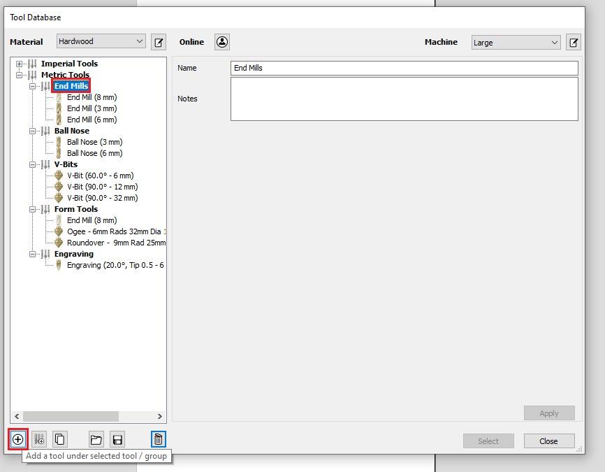
By pressing the Select... button, a new window named Tool Database appears, where all the tools stored in the database are listed.
In the Metric Tools subsection, we have a list of all tools in the metric system.
If our tool is not on the list, we can add it by clicking the plus (+) button in the bottom left corner.

The newly added tool will be added to the previously selected list (Tool Type).

In the Geometry section, under Units, we select millimeters, and in the Diameter field, we enter the tool’s diameter. In the No. Flutes field, we enter the number of cutting edges on the tool.
In the Cutting Parameters section, under the Stepover field, we enter the value that determines how many millimeters the tool will engage with the material per pass.
In the Feeds and Speeds section: Under Spindle Speed, we enter the spindle rotation speed. In the Feed Rate field, we enter the speed at which the tool moves while cutting the workpiece. In the Plunge Rate field, we specify how many millimeters per minute the tool will descend into the material.
The software saves all parameters for each tool and documents them in the tool database. To select a tool from the list, simply highlight it and click the Select button.

After selecting the desired tool, the next step is to press the Edit Passes… button in the Passes section below.
In this section, we determine how many passes the tool will make along the same path to reach the specified depth.
In our case, the final depth for this operation is 3.5mm, and if we choose 3 passes, the software will divide the final depth by 3, resulting in 1.16mm per pass (one complete pass along the defined vectors). The machine will follow the defined vectors three times, with each pass progressively cutting 1.16mm deeper into the material.


In the Specify Pass Depths window, we can individually control each pass, meaning we can specify the depth of each cut and how much the tool will engage with the material per pass.
To confirm the settings, we press the OK button.

The next function is Machine Vectors, where we have options to specify exactly where along the vector the tool will pass.
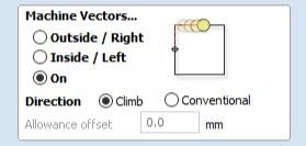
With the Outside / Right option, the software will generate toolpaths for the tool to cut along the outside of the vectors.
This function is used when we want to cut out a piece with precisely defined dimensions.

If the cutting tool has a 6mm diameter, the software will generate the toolpath 3mm away from the outside of the vector to achieve the exact dimensions of the final piece. If we had selected the On (On the Line) option, the final piece would have dimensions of 97mm x 247mm instead of the originally specified 100mm x 250mm.

If we want to engrave or groove a design, we can select the On (On the Line) option. This way, at the end of the process, the cut where the tool has passed will have a width of 6mm, which is the same as the diameter of the tool.

The Inside/Left option allows us to groove a recess with precisely defined dimensions, as the tool will move along the inside of the vectors. The effect of this is illustrated in the images above.
The Ramp effect is essential for correctly processing the material. With this effect, we control how the tool will enter the material. A direct 90-degree entry into the material with an End Mill cutting tool is illogical because the bottom segment that first enters the material doesn’t have a cutting edge on the underside, so it cannot remove the material. For this reason, we use the Ramp Effect, which allows the tool to enter the material at a predefined angle. We enter this value in the Ramp section under Specify Ramp...

We select Angle and input the desired value in degrees in the adjacent field. In the Type section, we choose the method by which the tool will enter the material: Smooth provides a straight-line motion for entry. Zig Zag creates a stepped pattern. Spiral generates spiral movements for entry.

The final step is to save the toolpath and prepare it for export by clicking the Calculate button.
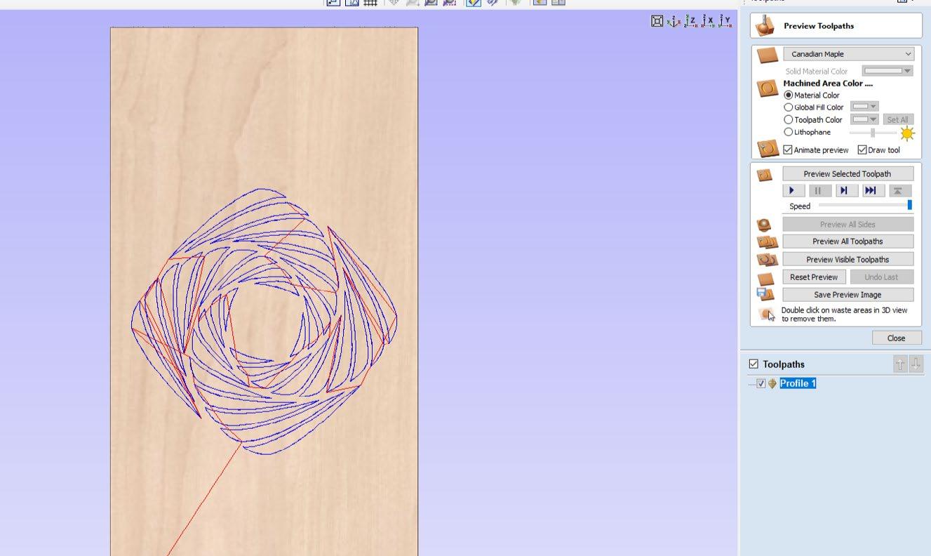
The software provides a graphical representation of the toolpaths and shows where the tool will move during the processing. Blue indicates the toolpaths on our drawing (vectors), while red shows the path of the tool when it is outside the material, moving from one vector to another. In the Preview Toolpaths window, we have options to simulate the entire toolpath, and the software generates a graphical representation of the final product and the processing steps.
Once we finish simulating the toolpaths, we need to switch back from the 3D view to the 2D view. This can be done by clicking the 2D button in the top section of the interface on the left side.

In the Toolpaths section on the right side of the interface, we have our toolpath. If we select it, the entry and exit points, as well as the direction of the tool’s movement, will be displayed on the drawing.

There is one last part of the drawing (the letter in the center of the design) that still needs toolpaths. We can do this by selecting the vectors, and then in the Toolpaths section, we choose the desired function to apply the toolpaths.

From the Toolpath Operations section, we select the Pocket Toolpath option, which is a different operation from the 2D Profile Toolpath. The first operation is already completed, and the software shows it in the Toolpaths section (in our case, named Profile 1). The second operation (Pocket Toolpath) will be performed with a different tool and different parameters. This function is used to create pockets (recesses) in the material with precisely defined dimensions.
In our case, we will use this function to remove material from the interior of the letter “R” and achieve the effect of an engraved letter.
As before, it is important to enter the value for the Final Depth in the Cutting Depths section, under the Cut Depth field.
From the Tools section, we select the appropriate tool and click the Select button.
In the Passes section, we enter the appropriate number of passes. Just below that, we can notice a new type of function where we define the pattern by which the tool will remove material. We have the option to choose between Offset and Raster patterns.


We select the Ramp Plunge Moves, Write a name for our file and click on the Calculate button.

As before, by clicking the Calculate button, a new window opens in 3D view, where we can see a graphical representation of the toolpaths for processing the vector and options to simulate the process.

We can see in the Toolpaths section that there is another toolpath, which is the Pocket Toolpath—the one for which we just adjusted the parameters. It is named Pocket 1. When selected, we can see the path of the tool while it is outside the material (shown with a red line) and the toolpaths for processing the interior of the letter (shown with blue).
The final step is to save the two generated toolpaths (Profile 1 and Pocket 1) in a .NC file so that they can be used to process the material with the machine.
We select one of the toolpaths, and in the Toolpath Operations section, we click the last button named Save Toolpath. A new window with the same name will appear, where, in the Post Processor section, we choose RADEK (.nc, .cnc). We select one of the toolpaths and click Save Toolpath(s) to save the toolpath for further processing.


A new Save As window will appear, where we can name our file and choose the location where we want it to be saved.


We repeat the same process for the second toolpath. With this, we have finished setting the toolpaths and parameters.

The next step is to transfer the newly generated files into the NC Studio software, through which we will execute the G-code for processing the workpiece.
To begin the cutting or engraving process, we first need to prepare the machine for operation. This process consists of several steps:
Placing the appropriate tool for the job
Setting up a MDF backing board
Placing and securing the workpiece
Turning on the machine, the computer, the cooling pump for the spindle, and the vacuum pump
Preparing the NC file
Placing the appropriate tool for the job
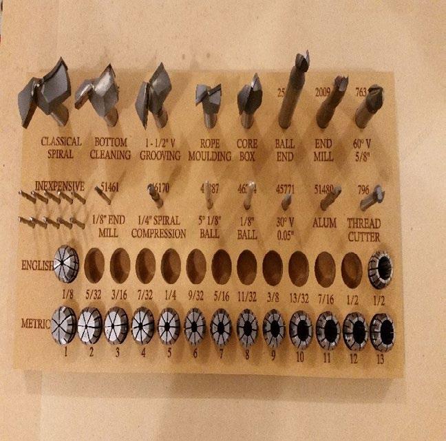
Depending on the operation, we choose the appropriate tool. Using a wrench, we loosen the nut holding the collet, insert the tool into the collet, and then tighten it, making sure not to over-tighten the nut.

Placing the backing board and workpiece
Under the workpiece, we place a backing board, such as MDF, to ensure a good vacuum, which is crucial for securing the workpiece. The workpiece MUST remain static during the operation of the machine.
If the machine operates without a vacuum pump, we use clamps to secure the backing board and the workpiece to the worktable.
We place the workpiece on the backing board, and after turning on the vacuum pump, we need to check if it is properly secured.

Turning on the machine, computer, cooling pump, and vacuum pump
Once the previous steps are completed, we turn on the machine. This is done by deactivating the emergency stop and pressing the ON button on the machine.

We turn on the computer through which we control the machine. The cooling pump for the spindle is powered on.


The vacuum pump is turned on using the switch.

The software responsible for controlling and operating the RK-132-ECO model is NC Studio. This software performs all standard operations such as parameter setting, axis calibration, spindle and distance adjustments, and processing of G-code commands and files.
After installing the software, it is necessary to connect the personal computer to the control board, which directly communicates with the CNC drivers and controls the machine. If the control board is not connected to the computer, the software will not start.
The control board is attached to the PCI slot on the motherboard of the computer, where it is powered and facilitates communication between the computer and the machine.


When we start the NC Studio program, it greets us with a workspace consisting of four main windows and several subsections with commands.

The first and most important function is to home the machine (Homing sequence), which we do by clicking the Operation button from the main menu bar and selecting the Move to Reference Point option. In the newly opened BKREF window, we need to click the All Axis button. This starts the homing sequence, without which the machine cannot operate properly. It is essential to perform this process every time the machine is started.
To add a new file for processing, we click on the File window in the upper left corner and select the New option, then Open and Load. Once we have set up the already attached file, we need to reset the axes on the workpiece. This is done using the Jog option (active movement of the axes) in the Panel section, and the reset is performed in the NC State section.

In the Manager section, we have access to all the uploaded files.

In the Panel section (Manual Movement), we have several options for moving the axes.

The X+ and X- buttons control the movement of the X axis, Y+ and Y- for the Y axis, and Z+ and Z- for the Z axis. To the right of these buttons are the intervals for movement. The Jog option, when selected, allows continuous movement as long as one of the X, Y, or Z buttons is held down.The other values allow movement based on a pre-defined distance. For example, if we select 5mm and click X+, the X axis will move exactly 5mm to the right. Rapid Movement (fast movement of the axes) is performed by pressing and holding the Ctrl key in combination with any axis movement button.
We manually move the axes to the edge of the workpiece and lower the Z axis until the tool touches the surface of the material and can rotate freely.
Next, in the NC State section, within the W. Coord. (Work Coordinates) window, we individually press each field to zero out the axes.

The axis is successfully zeroed when the coordinates in the W. Coord. field change to 0.000. If they are the same as the opposite coordinates on the left in the M. Coor. section, we need to click on the field where they are displayed.
In the adjacent Feedrate and Spindle rev. sections, we set the machine’s working speed—how fast it will cut through the workpiece—and the spindle rotation speed.

The status of the limit sensors can be viewed in the IO State window, where a red-filled circle indicates a properly calibrated and functional sensor.

Above the NC State section, there is an indicator for the limit switches, showing their current status.
