


The StarCAM software is responsible for generating and optimizing toolpaths for the machine to process the material and setting all remaining parameters. To start processing a drawing, it must be in DXF format (Vectors).

After processing the DXF file in StarCAM, we will transfer the newly generated .CNC file to the machine’s directory, where the part will be processed.
The first step is to connect the USB token for the StarCAM software to the personal computer and launch the program.
A StarCAM window will appear with several options, from which we need to select the StarCAD application.

After clicking the button, a new window named StarCAD will appear. Here, we need to import the previously generated DXF file and further process it by defining cutting paths, setting parameters for where each external and internal cut should start, specifying the cut type, and generating the file required by the machine for processing.

To import our DXF file into StarCAD, we need to click on File > In File from the menu in the upper left corner. This will open a new window titled Open, where we need to locate the desired file and import it into the software.


In the Files of Type section, we select DXF (.dxf), locate and select the desired file, and click Open. For a quick preview of the drawing, the Open window includes a section on the right side where the selected drawing is displayed.

Clicking the Open button brings up a new window named Edit DXF, where our drawing is displayed along with several additional options for making modifications to the drawing.

By pressing the OK button, our drawing is placed on the workspace, and we can now define toolpaths and processing parameters. The next step is to click on Output > AutoPath Setup from the menu bar.

A new window, Auto Set Paths, will appear, offering various options and parameters for processing.


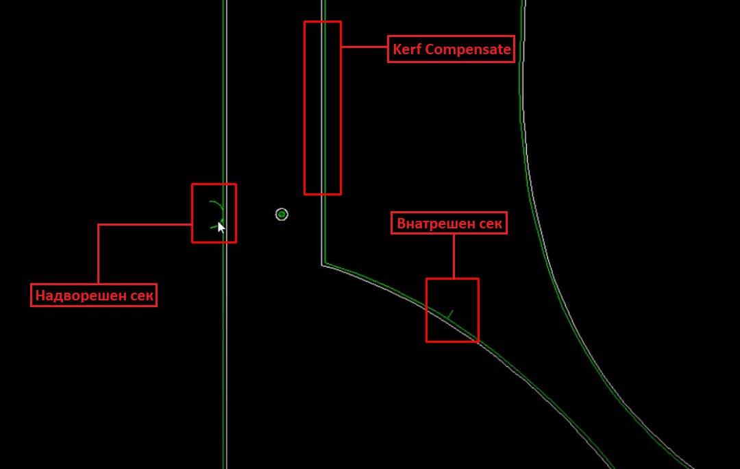
In the Entries/Exits Set field, we define how the machine will start and finish external and internal cuts. Depending on the drawing, we can choose a quarter-circle, semicircular, or rectangular cut.
When the machine begins cutting the sheet, the first cut must start outside the vectors (lines) of the drawing. All internal vectors within the drawing are processed in a way that the first internal cut is made on the scrap parts of the material. This ensures that the final product matches the design exactly and does not have unwanted cut marks.
In the Outline Section we define the cutting parameters for all external lines. In the Entry & Exit subsections, we specify the entry and exit cuts for the external lines of the drawing. In the Type field, we select the type of cut. In the Radius field, we set the angle of the cut.
In the Inline Section we define the cutting parameters for all internal lines. In the Entry subsection, we have the following options: Pierce in Corner: Starts the cut at the corner of the drawing and is used in most cases. Break Longest Entity: Starts the cut from the middle of the internal lines. The choice depends on the shape and type of the drawing.

In the same window (Auto Set Paths), we select the Contours Kerf / Tabs Set section and check the Parts contours size kerf option from the Kerf Compensate field to set tolerances during processing. This option significantly improves the finish of the manufactured part.

To save the file and all parameters, click the NC button located in the upper central region. Upon pressing the NC button, a new window titled Save As will appear, where we enter the name of the drawing. In the Save as Type field, we select either the .CNC or .NC option.


After pressing the Save button, several windows will appear with the remaining parameters to finalize the settings.

In the first window, Whether you need to quickly move to the starting point?, click the Yes button. This will open a new menu from which we select the Coordinate Points option.

In the newly opened window, enter zeros and click OK.

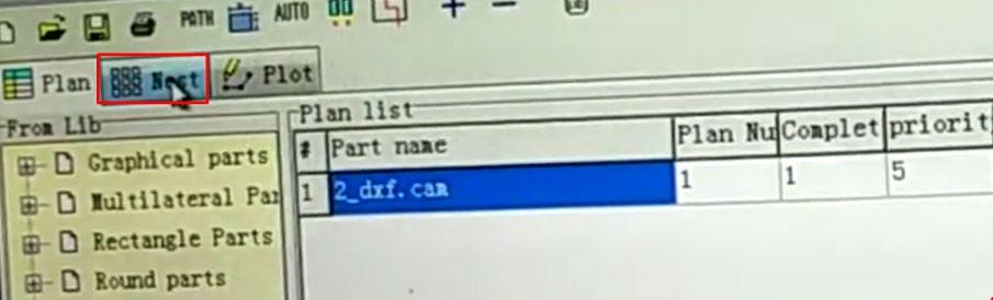
From the main window of StarCAM, we select the StarCUT software, which is responsible for nesting and organizing multiple pieces. All the functions mentioned above from StarCAD can also be performed in StarCUT.

By clicking the StarCUT button, the main workspace opens. From here, we need to select AutoPath Setting from the Nest Setup menu in the toolbar.


This opens the familiar Auto Set Paths window, where we will set the parameters and tolerances for cutting.
In the Entries/Exits Set window, there are two main sections: Outline and Inline.
The Outline section is responsible for all cuts on the outer side of the drawing, while the Inline section is responsible for all internal cuts.
Both sections have subsections: Entry and Exit.
The Entry option determines how the cut will enter the line for processing, and it can take various forms, such as rectangular, semicircular, quarter-circle, etc.
The Exit option defines how the cut will exit the line for processing.

In the central part of the window, there is an option called Internal same as External. When this option is checked, the software will generate both external and internal cuts using the same method. The same parameters set for the external cuts will apply to the internal parts of the drawing.
The next step is to go to the Nest Options window. In the Nest Settings section, under NEST Start, select from which side of the workpiece the drawing will be generated.

The next step is to select Nest Setup from the main menu, then choose Plate Setup, which will open a new window titled CUT.


In the CUT window, under the Plate DataInfo section, we enter the dimensions of the workpiece.
- In the Length field, enter the length.
- In the Width field, enter the width.
- In the Thickness field, enter the thickness of the material.

The next step is to attach our drawing, which can be done by pressing the + (Add Part) button.
This will open a new window where we need to select DXF files as the file type, locate our drawing, and import it into the software. After selecting the file, click Open, which will open another window for previewing the opened file. Once ready, click OK.
On the right side of the interface, a window named Parts Preview will appear.
Clicking the Move Entries button opens a new window titled Entries and Exits, where we define the position for the entry and exit cuts. By clicking on any point on the external or internal lines, we set the position for the starting and ending cuts.
At the moment we click, a blue indicator appears, showing where the cut will be placed.


Once we finish setting the entry and exit points, click the OK button.
The next step is to click on the Nest section, which opens a new window containing a graphical representation of our drawing and all the toolpaths that the machine will follow during the processing.


The green lines represent all the vectors from our drawing, the blue dashed line shows the toolpath the machine will follow during processing, indicating where the cut will start and where it will finish. The yellow line represents the area where the machine will operate, specifically showing the limits of the movement of the head/torch.
In this section, we can copy parts and create a template for processing.
Once we’ve finished reviewing and editing the design, we need to select the NC Output option from the central toolbar by clicking the NC button.

A new window will appear where we enter the name under which we want to save our file, specify the location, and choose the format (either .CNC or .NC). After selecting the desired format, click the Save button.
This opens another CUT window, where if we choose Yes, we are given the option to review the code and toolpaths. If we click No, the window will close, and the file will be saved successfully

With this, we have completed the file processing and can transfer it to a USB stick to begin preparing the machine for processing.
Once we finish preparing the drawing, we transfer it to a USB stick and get the machine ready for material processing.
Preparation Steps:
Check Plasma Pressure: Ensure the plasma cutter has a pressure range of 4 to 6 bars.
Check Oil Level: Verify the amount of machine oil in the manual dispenser’s canister. If the machine hasn’t been used for a while, move it along the axes and operate the handwheel to evenly lubricate the linear rails and prevent damage.
Check Grounding Connection: Ensure the grounding clamp is securely attached to the machine. If it’s not connected, attach the clamp to the grounding pins or the physical stop on the sides of the machine.
Start the Machine:
Deactivate the emergency stop.
Press the ON/OFF button to start the plasma unit. Activate the fuse located at the rear of the unit to power up the plasma cutter.
Test Plasma Arc Generation:
On the XPTHC control panel, adjust the IHS HEIGHT on the right potentiometer to set the distance between the torch and the material.
Adjust the cutting voltage on the left potentiometer. For example, for a 3mm thick steel plate, the voltage should be around 120V, and the cutting height should be set to “15,” which results in a 4mm distance between the torch and the material.
Finally, the StarFire Controller’s user interface will appear on the main control unit.


We gain access to the main sections of the software through the F1 to F8 buttons and ESC. By pressing the first button, F1 (ShapeLib), we enter the file containing preloaded designs from the machine’s internal memory. All that is left to do is adjust the parameters and select the starting point for the work.

We navigate through the main directory using the four yellow arrow keys (↑←↓→) on the right side of the controller. Once we position ourselves on the desired drawing, we select it by pressing the Enter button. This section (Library) contains all the previously prepared drawings. If we want to access our own drawings, we need to press F2 (Files) from the main menu, which will open a new window.


In this section, we have several options for preparing and selecting a file for processing. By pressing the F1 (Disk File) button, we gain access to the list of all files transferred to the machine’s internal memory. Pressing the F2 (U Disk) button will show a list of all files on the connected USB drive. Note: If the USB stick is not connected to the machine, the U Disk list will be empty and display the status “U Disk Not Found.”

We have the option to transfer selected files using F5 (CopyToUDisk) or (CopyToDisk) from the internal memory to the USB stick and vice versa. By pressing F7, we select the desired file and it takes us to the main interface.
In our case, we will choose one of the pre-prepared drawings from ShapeLibrary To return to the main menu, we press the ESC key, navigate back to the main menu, and press F1 (ShapeLib) to access the list of preloaded drawings and select one of them.

The next step after attaching the drawing in the main menu is to set or confirm the characteristics of the part. In the fields Size1, Size2, R9, we enter the dimensions according to the schematic shown in the lower-right corner of the interface by pressing the number buttons on the right side of the screen. Once we finish entering the values, we need to press Enter to save them. Next, in the Entry L field, we choose the starting line for the processing to begin. We press Enter and then select where the plasma torch should finish by using the Drop L option. It is recommended to select only the first parameter.

After setting all the parameters, we press the Apply button (F7) and then the OK button (F8) to confirm the settings.
From the main menu, we press the F3 (PartOption) button, which opens a new window where we can set the starting point for processing the part using the F1 (StartPoint) option. We can adjust the proportions of the drawing using F2 (Scale), create a template from the same drawing using F3 (Array), and set parameters for the initial piercing in the part using F5 (SelPierce).

Once we fill in the desired values (usually, PierceTime is 0.3), we press F7 (Save) to save the settings.

Back in the PartOption menu, by pressing F1 (StartPoint), we determine the starting position of the torch. Initially, the position is marked with a red cross. Once we press F1, the position and color change to blue. We continue pressing F1 until the cross is positioned at the desired location.

If we want to produce multiple identical copies of our design, we can do this by pressing the F3 button for the Array function. This allows us to create an array of the design, duplicating it as needed.

A new window appears where we enter the number of rows in the Rows field and the number of columns in the Columns field. By pressing the F1 button, the software generates the template.

The same process can be performed by entering the ShapeLibrary by pressing the F1 option from the main menu and selecting the F1 (Nest) option.


A new window appears, displaying a representation of the worktable along with several Nesting options.
Setting the Plate Size:
Press F5 (STEEL) to define the dimensions of the plate where the template will be generated. In the WIDTH field, enter the width and press ENTER. In the LENGTH field, enter the length and press ENTER. Enter an interval value of 0.000 and press ENTER again.
Loading a File:
Press F1 (Load) to load a file, which presents two options.

The F1 (GLIB) option provides access to all files in the ShapeLibrary, while the F2 (FILE) option allows access to all files stored in the internal memory or USB.

We navigate to the desired file using the arrow keys on the controller and press OK.
A new window appears where we need to enter the number of pieces we want the software to generate. After entering the value, we press Enter to confirm.

With this, the software generates the specified shapes and allows us to add extra shapes by pressing the F1 (LOAD) option again or to move and reorganize them. We can individually select any part and make direct changes only to the selected piece. The software provides a visual indicator by highlighting the selected part in red, while in the list on the top right corner, the selected part is marked in yellow.

By pressing F7 (OK), a new window appears where the software prompts us to name the new design and prepare it for processing. We enter the name using the numbers on the main panel and press Enter to confirm.

From the main menu, we press F7 (ManualMove) to begin zeroing the machine’s axes, determine the origin point and start preparing for processing.

By pressing any of the four arrow keys (↑←↓→), we manually move the head to the position where we want our Origin (starting point) for the drawing and select the F3 command. To save this point, we press F4 (REF0), and we can notice that the X and Y axis coordinates in the lower right corner are now set to 00000.000.

We need to set the processing parameters.
Set the voltage (Voltage) according to the thickness of the piece, enter the value, and press Enter. Change the speed (Speed), press Enter, and enter the current power (Amps) value, then press Enter. Although we prefer to set these values using the potentiometers on the plasma machine and the XPTHC panel, as it is a bit more practical.
With this, we have completed the zeroing and parameter adjustments, and the machine will begin processing the piece from this point.
The Piercing Time or the interval for piercing into the material can be adjusted by going to Settings > Plasma > Piercing Time. The recommended value is usually 0.3.
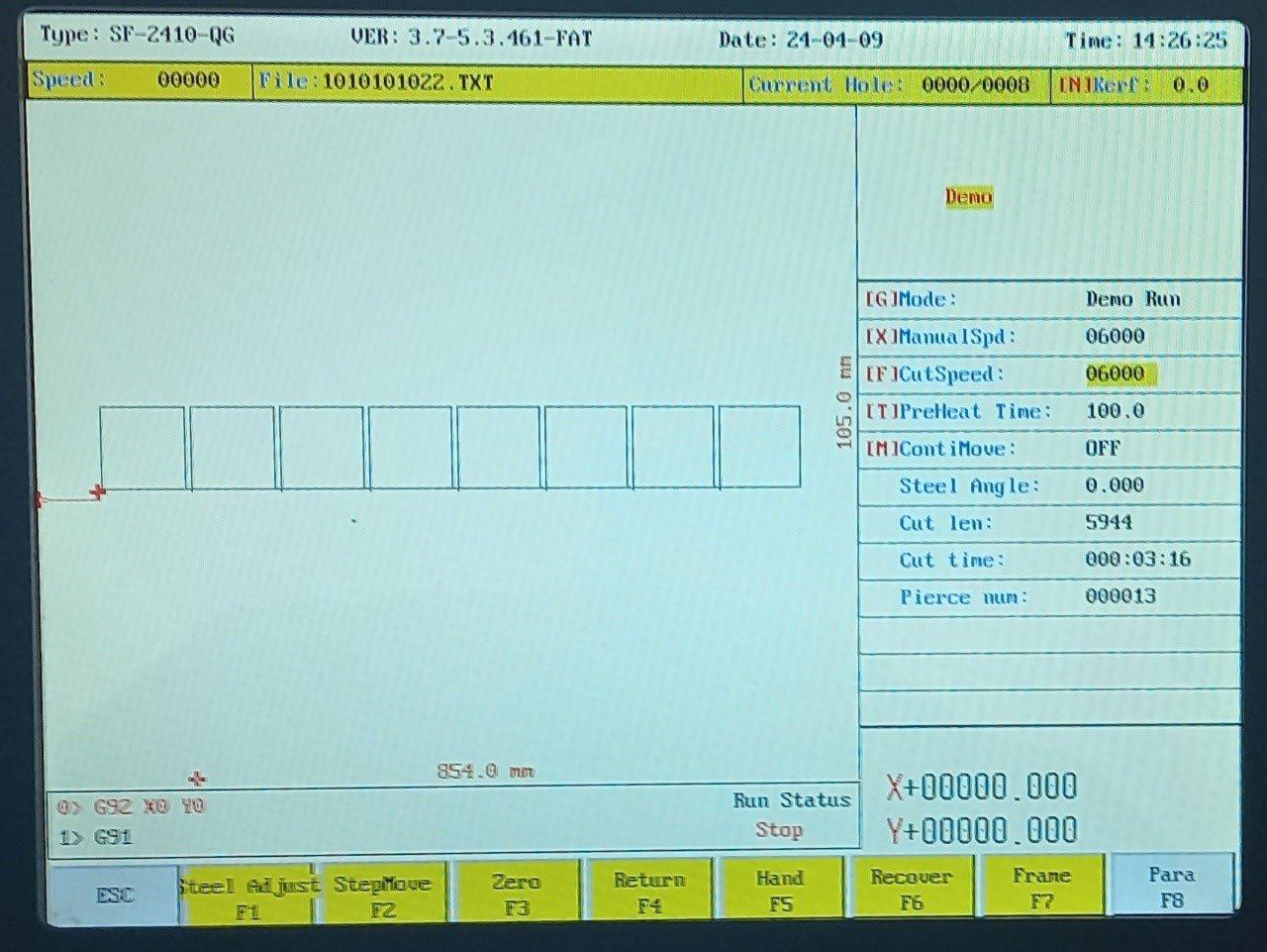
By pressing the F7 (Frame) button, we can check the section where the machine will perform the material processing. To see exactly how the machine will cut the design, press the (X) button on the right side of the controller, and in the top right corner, the “Demo” field will be highlighted. In this mode, the plasma will not generate a beam, but the machine will move the axes along the path where it would normally cut.
To adjust the cutting speed (working speed) for the material, press the F (yellow) button, which opens a new window with the option CUT SPEED [0-10000]. Here, you need to enter the desired speed in mm/ sec. Once the value is entered, press Enter to confirm. For thicker pieces, a lower speed should be selected, and for thinner ones, a higher speed. For example, for a 3mm thick sheet, the speed should be set to 4500mm as indicated in the top-right corner under SPEED: F
Next Step: Press Auto (F1)
Depending on the piece being processed, the voltage must be adjusted. This can be done by turning the left potentiometer left or right, with the voltage displayed on the indicator near the potentiometers. The right potentiometer adjusts the distance between the torch and the material surface. The torch height can also be adjusted from the main screen by pressing the S+ and S- buttons.
Additionally, the processing speed can be controlled using the blue F+ and F- buttons on the main screen.
Next Step: Select Amperage
Next, choose the amperage for processing the piece. Go to the plasma device and adjust the power by rotating the main potentiometer left or right to increase or decrease the arc’s power. For a 3mm thick piece, the optimal amperage is around 65A.
Start the Process
Press the I button in the bottom-right corner of the screen to start the machine, and it will begin processing the design.
Advanced Settings
To access advanced settings, press the Menu button located on the left control panel. Press and hold the Menu button for 2 seconds to adjust parameters P1, P2, P3, or for 4 seconds to adjust parameters P4 and onwards.
Parameter 1: Adjust spark voltage (e.g., from 50V to 150V)
Parameter 2: Gun delay (10 milliseconds)
Parameter 3: Adjust torch height (e.g., from 05 to 99)
Parameter 4: Adjust head distance from the cutting piece (e.g., from 00 to 99)
Parameter 5: Gun setting
0: Setting
1: Sample mode
Parameter 6: Logical limit setting
0: Normally open
1: Normally closed
Parameter 7: Automatic torch height adjustment
0: Slightly effective
1: Very effective
Parameter 8: Raise the torch after cutting the piece
Parameter 9: Change plasma cutting gas
Errors (E1 to E5) During Cutting
E1: Incorrect communication due to incorrectly connected cables
E2: Occurs when the torch hits or the corner signal is not well-adjusted
E3: Cutting problem. Check the connection from the controller to the plasma and from the voltage distribution module to the torch. Incorrect Piercing Time (go to Settings > Plasma > Piercing Time and set to 0.3)
E4: Excessive voltage for cutting. The problem occurs when the voltage is around 30V higher than recommended or the value is too high/low.
E5: Torch hitting the piece. This error can be cleared by pressing the Menu button.
Torch Consumables
Depending on the material type and thickness, the torch nozzles may wear out (as consumables). This usually happens after 10-12 processed sheets, and the effect is noticeable in the cut quality and arc shape. In such cases, the nozzles need to be replaced. Nozzles come in pairs and are of different sizes. The smaller one is installed first, followed by the larger one. The nozzles should be carefully screwed in and tightened.
After prolonged use, the nozzles may expand, resulting in a wide cut and poorly processed pieces. The most commonly used nozzles are 1.5.
Resuming a Job After Stopping
If there is an issue with a piece that has stopped or didn’t cut well, the process can be resumed from the point where it stopped. Follow these steps:
From the Auto menu, choose VIEW → select TEST MODE
Press the green I button to start, then stop.
Press F6 → N-PIER, and input the piece number.
Press the number and dot, then add zeros until the end, and press Enter. Press the plasma start button to resume. Once the work is completed, turn off all machines.
Machine Shutdown
To shut down the system:
CLOSE: To close the error message.
S+ “ ” S- “ ”: To adjust the torch height.
CUTTING: Check the torch, typically the plasma will run a 1-second test and create a hole. It will then show Error 3, as the machine doesn’t continue cutting.
X: Test mode (machine runs without plasma).
G: If pressed, the machine continues moving automatically if it’s in manual mode. In the right panel, the angle of the piece is shown, which can be adjusted in the ASSIST menu (F8).
Preheating
Plasma must be preheated along the edge of the cut to avoid imperfections.