Haixun Speed Design is the software responsible for precise design and arrangement of all types of cabinets, wardrobes, kitchen elements, nightstands, dressers, drawers, tables, as well as any type of furniture or any design.
The software interface is user-friendly and contains all the necessary tools for efficient and fast design of any type of furniture, including functions for grooving and implementing hardware and joining elements.
The process begins with Haixun Speed Design, where in the main menu, under the ‘Start’ segment and the ‘Function’ field, we select the ‘New Order’ button, which opens a new window where we can enter all the data related to the design we will work with such as: order number, material supplier, order and delivery date, client information, material cost, product manufacturing cost, and most importantly, all the details about the material we will be using (name of the material, it’s thickness and color, as well as its price).
Once we click the OK button, a ‘System Tips: Create order successfully’ window should appear, allowing us to proceed with the design and product parameters.
We can start by selecting the ‘New Product’ option from the ‘Function’ segment, which will give us access to a new window where we can start designing our product.
To start the design, click on the ‘BlankFrame’ button, which will open a new window titled ‘Add Component,’ where the absolute dimensions of the finished product need to be entered. This option will generate an empty three-dimensional frame to which we can attach elements on all sides. The product dimensions and material thickness are entered in ‘Parameter Information,’ under the ‘ParamValue’ column, while the height, width, and depth are indicated in the adjacent ‘Remark’ column.
The next step is to fill the empty frame with the desired elements (top, bottom, side, and internal panels), which can be found in the ‘SystemModule’ window. By double-clicking on the desired option, a new window called ‘Add Component’ will appear, where we can change the dimensions, thickness, and spacing of the components.
To add complex elements (such as drawers or doors, which contain hinges or rails), we first need to find and select them by double-clicking in the ‘Cabinet ➜ System Module ➜ desired folder’ window, which contains the desired elements.
To change the dimensions of any segment of the added elements, such as drawers, doors, or holders, we need to select the desired element, and in the ‘Module Parameters,’ we have options to modify the dimensions, position, and spacing of the element.
The empty frame (BlankFrame) can be divided into multiple segments, which we achieve using the ‘Split Space’ function, providing options to divide the space starting from the top or bottom, the front or back of the frame, or from the left or right.
When implementing built-in elements, we have additional options for positioning them within the selected empty frame. We can adjust the element’s position relative to the empty frame (up and down, left and right, and forward and backward), as well as its final dimensions, which are adjusted in the ‘Parameter Information’ in the ‘Add Component’ window.
To add and adjust drawers and hinges, we select the empty space where we want to implement the elements, and on the left side in Cabinet -> System Module -> Drawer, we can find a wide selection of pre-made drawer models. By double-clicking, we add them to our design, and the software automatically calculates the dimensions of the drawer sides.
The ‘Drawers Add’ window appears, displaying all the parameters for the drawer we’re adding to the design. It offers detailed options for the type of hinge, handle, and lock, as well as their positioning in the design. In the ‘Drawer’ section, we can adjust the dimensions of the drawer itself (with the software automatically generating these dimensions). The ‘Slideway’ section provides access to all parameters for the drawer rails, the ‘Handle’ section contains all the information about the handle, and in the ‘Lock’ section, we can configure everything related to the lock if we’ve chosen to implement one in the project.
1. In this section we select the number of drawers that we want to implement in the empty selection.
2. In this window we set the distance between the faces of the drawers.
3. Absolute dimensions of the drawer.
4. Alignment of the drawer in the empty selection.
5. Option for side grooves for rails.
6. Option for handle and handle holes.
7. Settings for the edged section (the part where the edge banding track is applied).
In the Slideway section, we have options for positioning and aligning the drawer slides, as well as all the specifications for the slides such as; manufacturer, length, width and thickness of the slides (The software itself generates the dimensions for the slides depending on the given dimensions of the empty frame in which we plan to implement the slides).
rail type alignment
The Handle section offers us options for the drawer handle, its positioning, dimensions and orientation. The software automatically generates the dimensions of the handle and the grooves in which it will be attached, so we need to input the correct values and dimensions for the handles that we plan to implement in our design.
The Lock section allows us to easily implement drawer locks in our design. In the adjacent fields we can change all the distances and dimensions for the locks.
CNC NESTING
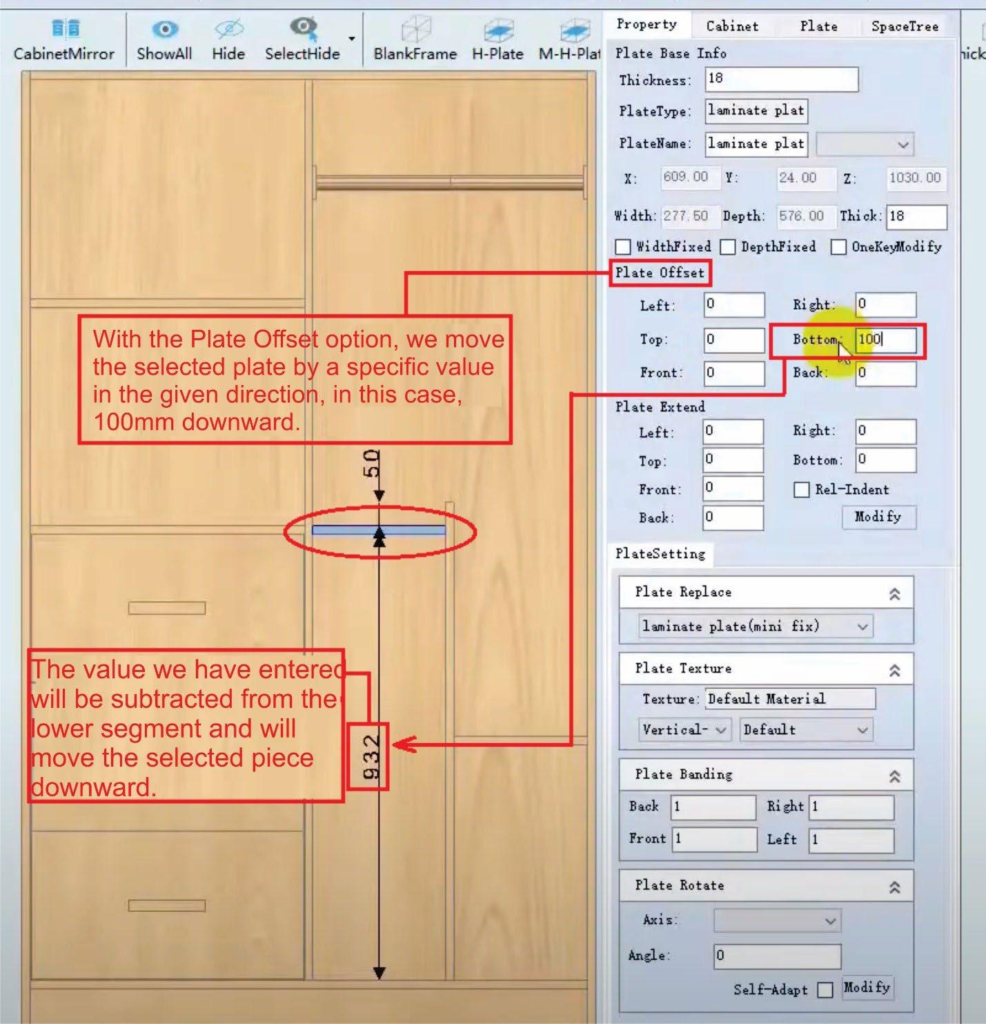
If we want to move one of the elements for a certain distance, we need to select the element itself and in the Property window, in the Plate Offset segment, we enter the desired value, by how much the element should be moved, and to determine the direction of movement, we need to enter the value in one of the fields: Left (Move from the left side), Right (Move from the right side), Top (Move from the top side), Bottom (Move from the bottom), Front (Move from the front side), Back (Move from the back side)
With the Plate Extend option, we can change/increase the dimensions of the attached plates in the design and this function works in the opposite principle of Plate Offset.
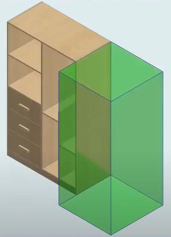
To attach a new blank frame to the existing design, we need to select a side/panel of our design to which we want to add the frame and by clicking on Blank Frame, we get a new blank frame pasted to the selected side
The new empty frame has the same orientation as the element/drawing it is attached to. To change the orientation, there are additional steps that we will discuss later.
CNC NESTING
We fill the newly added empty frame with elements and add shelves with the HorizontalPlate option. We select the space of the frame and from the segment for adding plates we click the HorizontalPlate option. We are greeted by the Plate Add window in which we have additional options with which we can select the number of shelves, the distance from the top and bottom to the first shelf and how much it should protrude or be recessed into the frame.
1. The average option allows Automatic generation and alignment of shelves in the Selected space. In the Adjacent field (marked With number 6) we enter the number of shelves that we want to be generated.
2. Sorting from above
3. Sorting from below
4. Protrusion outside the frame for a certain value
5. Protrusion from the internal Back side.
6. Number of shelves automatically generated with the Average option
If we want to cut a segment of the newly created element, we select the Chamfer option, which is located in the third segment of the top toolbar.
First step is to select the top shelf, and by pressing the Chamfer button, a new window called CornerCut opens.
1. In this field, we enter the value for how much to cut in width.
2. In this field, we enter the value for how much to cut in length.
3. Shelf thickness.
4. Option to cut through all pieces.
5. Option to align the shelves from the top by a specific distance.
6. Option to align the shelves starting from the bottom by a specific distance.
If we select the front element and add a new empty frame, the software opens a window with options for orienting the frame.
Each time we select an element that is oriented in a different direction from the one we are currently working in, the software will ask us in which direction we want to orient the empty frame.
The newly attached elements will be oriented according to the orientation of the empty frame and depending on which element (and from which side) they are attached to.
To add swing doors, we select the space where we want them to be implemented, and in the section Cabinet ➜ System Module ➜ Door Plate ➜ Swing Door, we can find various models and options for doors. Once we select the model we want to add to the design, a new window, DoorPlate Add, opens, where we can modify all the parameters.
1. The Hinge option allows us to implement hinges and holes for them, which the software will automatically generate if the Hinge option is selected.
2. Banding Setting is an option for configuring the edge banding of the doors. If we select this option, it signals the software to account for the thickness of the edge banding in relation to the doors, and it automatically generates their dimensions.
3. With the Handle option, we generate grooves for handles.
4. In this field, the material thickness for the doors is entered.
5. DoorType offers a choice between an external and internal type of doors.
The software automatically generates the dimensions of the doors based on the dimensions of the empty frame we have selected.
CNC NESTING
If we want any of the already added elements in the design to be divided into parts, we can do so using the Plate Cut option. A new window called Plate Segmentation opens, where we have options to divide the plate based on exact dimensions or in a ratio of one part of the plate to the other.
Additional options in the Plate Segmentation window are Divide Datum and Plate Gap. With the Divide Datum option, we can determine whether the cut/division will be made by height or by depth.
The Plate Gap function gives us the option to leave a space between the two segments created by the cut, based on a specified value.
Once we finish adding elements to the design, with the SlotAndHole option, we can check all the generated holes and grooves in the design.
In SlotAndHole, we have the options Hole Preview, Hole Modify, Add Hole and Slot, and Solid Preview Mode.
By clicking on the SlotAndHole ➜ Hole Preview option, we get a preview of all the grooves and holes in the design, which are automatically generated as we add elements. By clicking on the Hole Modify option, we can change the position of any of the grooves, and with the Add Hole and Slot option, we can add additional grooves and holes. By clicking on the Solid Preview Mode option and selecting any external plate, we make it transparent and gain better visibility into the interior of the drawing.
The software has a function to check the design and whether there are any conflicts between the added elements. By right-clicking in the empty space surrounding the design in our drawing, we get a menu window with several options, many of which are present in the work tabs. The functions we need to perform an element check are called Plate Check and Hardware Check.
If there are no conflicts between the plates and elements in the drawing, a message should appear saying “Plate is Normal” and “Hardware is Normal.”
Once we finish designing our model, we can save it by clicking the Designed button located in the top left corner and continue adjusting the remaining parameters to prepare the file for further processing in Haixun Speed Production.
After clicking the Designed button, a new window will appear with options for labeling, exporting, naming, adding, organizing in the order list, and many other useful tools.
From the top left corner, we click on the Start section, where we can add the drawing to the order list and have the software generate designs from the model. By clicking the Print option, a new window opens. When we click ➜ Export PDF, we get an isometric drawing of the design in PDF format.
CNC NESTING
To generate edge banding for the design, right-click in the empty space around the drawing and select the EdgeBanding Solutions option from the menu that appears, or choose EdgeBanding for manual adjustments.
After completing all the settings, we need to export the files from our drawing and add them to Haixun Speed Production for further processing and preparation of the G-code file.
First, we need to click on the ProductionInfo segment, which is the second-to-last option in the top menu, and select the ReportForm option. This will open a new window called Report, where we need to click on the ExportAll option.
This process generates multiple Excel files containing all the parameters and dimensions of the design.
The final confirmation that all files have been generated is the window with the message: Information: Export finished!
The next step is to start the Haixun Speed Production program, which is responsible for the quick and efficient optimization of all elements from the plate cutting design. The software automatically generates the orientation and position of all elements on the plates, eliminating material waste.
Haixun Speed Design export procedure generates 5 different files: 3 Excel files – named according to the order number 1 .bmp image – named according to the order number 1 .xml file – named right before exporting the file
Right after we start the program, we are greeted with a new workspace window where, in the RawMaterialSpecification section, we need to right-click on an empty area and select the “choose raw material” option from the menu.
Once we click on the “choose raw material” option we are greeted with a new window named choose raw material
1. This column contains checkboxes that, when ticked, will implement the selected plate for optimization and processing.
2. Name/type of plate, where we can name the plates based on our needs.
3. Length of the plate
4. Width of the plate.
5. Material thickness
6. Inventory (how many plates we have remaining).
7. Color.
It is necessary for all names and color names to be accurately labeled to avoid conflicts during optimization and G-code generation.
Once we select the material, we need to navigate to the adjacent segment to RawMaterialSpecification, called Boardsize.
In Boardsize, we right-click on an empty space again and select “import product information” from the newly opened menu. When working in Haixun Speed Design with the ReportForm ➜ ExportAll option, we generated several files, four of which are Excel files with the .xml extension, and one image. We need to select the file named after the project (in our case its “test”).
When the new window opens, the software will recognize the correct .xml file and will not display the Excel files at all.
Once we attach the file, the software will fill the tables with all the parameters/dimensions, and we will be left with optimizing the layout of the elements on the plates for processing.
The software will begin generating the layout of the plates once we click the calculation button.
After the software finishes the optimization, it takes us to the adjacent Optimization section, where we can review the orientation and arrangement of the elements on the plates for processing. In this section, we will set up the cutting tools and generate the G-code.
We have the option to manually move the elements on the workpiece using the moveboard function, or we can move them to another side (another processing plate) using the “to which page” option.
Right-clicking on any of the elements opens a menu with several options, where we can find all the options for moving and rearranging the elements.
If we want to change the processing order of the pieces, we first need to select the “check work order” option, which will display numbered indicators showing the current sequence. Next, we choose “set work order” and manually click on the plates to assign them a new order. The order will depend on the sequence in which we clicked the elements. Once we finish arranging, we right-click and select “setting finished.”
To add a new type of processing material to the Haixun Speed Production database, select the “raw material manage” option from the “material (O)” menu located in the top-left corner of the menu bar.
After selecting the option, a new window called “raw material manage” opens, where we have options to add and configure both new and existing materials for processing.
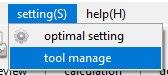
In order to add additional knifes (Tools) to our library we need to chose the option Tool Manage which can be located in the Settings (S) menu bar
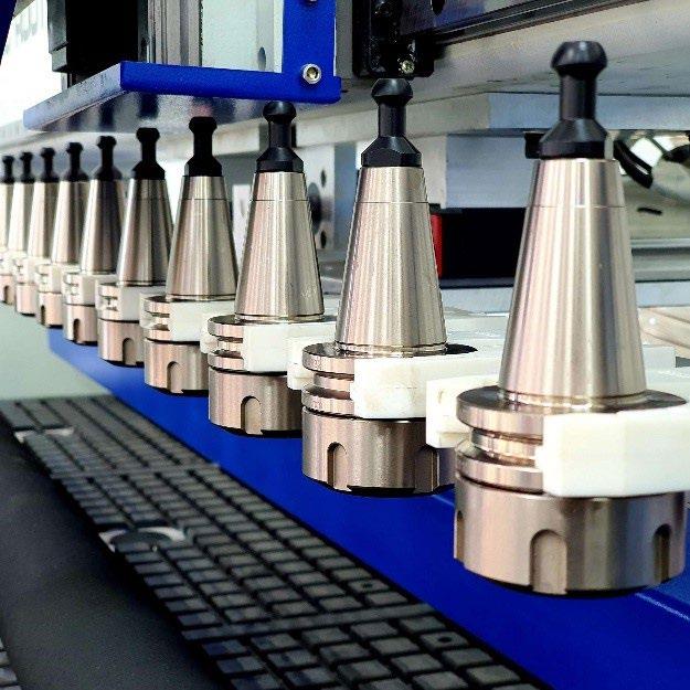
By choosing the option we are greeted with a newly opened window named Tool Management in which we can add or modify new and existing knifes in the database.
The “add” option adds a new blade to the list, while the “edit” option allows us to modify all parameters and values of the selected blade. The “delete” option removes the blade from the list. In the “Speed” section, we set the machine’s processing speed, including the cutting speed.
After configuring all parameters, we need to generate the G-code, which controls the machine by specifying movement directions, speed, blade changes, and other processing functions. To generate the G-code, we click the “generate G code” button.
A new window with additional parameters will appear, allowing us to finalize the export of the G-code file.
The “System Hints” window notifies us that the operation has been successfully completed.
The prepared G-code file is transferred to a USB stick and can then be added to the machine’s database.
CNC NESTING
By generating the G-code, we’ve finished all the steps in Haixun Speed Design and Haixun Speed Production, and the only thing remaining is to import the code into the machine and set up all the processing parameters. The main controller is LNC, and all machine functions are operated through it. To start the machine, rotate both Emergency Stop buttons slightly to the right to restore power, then press the ON/OFF button.
As soon as the software loads up we are greeted with the main interface
machine start button
we need to turn both emergency stop buttons to the right a small degree until we feel the button twists.
The main interface is divided in 3 sections:
Section with coordinates and G code preview
Section for control of the axis and all elements of the machine
Section with main and most frequently used tools
In the section for coordinates and code preview, there are several windows:
The ABSOLUTE window displays the zeroed position, i.e., the position of the axes when they are zeroed on the workpiece.
The MACHINE window shows the actual coordinates of the axes after homing the machine. (For proper operation, it is necessary to home all axes after every machine startup.)
The DIST TO GO (or Distance to Go) window shows the remaining travel distance for the axes.
The window on the far right allows us to review the entire G-code for the design. (For example, the first line M03 S18000 indicates that the M03 function will start the spindle, and S18000 shows that it will rotate at 18,000 RPM.)
In the adjacent section, we can find all the buttons for active axis movement as well as control over all machine elements.
The orange buttons are the ones that move the axes, and they are labeled:
X+ and X- buttons move the X axis (the head) left and right Y+ and Y- buttons move the Y axis (the bridge) forward and backward
Z+ and Z- buttons move the Z axis (the spindle) up and down 4+ and 4- buttons are used to move the rotational axis if the machine has 4 axes (X, Y, Z, and rotational)
The blue RAPID button allows us to move the axes at maximum high speed! As long as it is pressed and the green triangle in its upper-left corner is lit, all the axes will move extra fast.
To move the axes, it is necessary to select one of the options JOG or INCJOG (incremental jogging). To move them using the MPG controller handle, the MPG option must be clicked.
On the right side of the orange buttons for axis movement, there is a panel with all the auxiliary elements of the machine, such as: the dust extraction system, clamping rollers, vacuum pumps, positioners, tool magazine, work surface cleaning system, and the dust cover for the spindle itself.
When we click the Dust Cover 1 option, a dust cover on the spindle pneumatically lifts for tool changes and lowers during operation.
By pressing the POS1 button, we command the pneumatic positioners at the front end and left side to activate, allowing easy and efficient alignment of the workpiece on the table
The ROW MAG. P/B button is responsible for manually moving the tool magazine forward and backward. The magazine, when in the closed position (back), is located under the bridge. It moves forward automatically only when the machine needs a tool change, or we can manually call it to change the tool order or any of the tools.
The DUST CLR (or dust clear) button is for automatic cleaning of the work surface. The machine has a built-in system that pneumatically lowers a dust extraction element across the entire surface of the work table and moves the bridge from one end to the other, removing all the sawdust in its path.
The Press Roll Switch is the button with which we raise and lower the rollers on the machine. The rollers are attached to the bridge, and their function is to further secure the workpiece while the machine is operating.
The VAC1 and VAC2 buttons are for activating the vacuum pumps. If the buttons are not pressed and do not light up yellow, we cannot start the pumps.
The SP. RUN button activates the spindle, and when its pressed the spindle starts rotating. The SP. STOP button deactivates the spindle. The bottom section contains the main tools for controlling the machine.
The HOME button begins the homing sequence of the machine.
With each startup of the machine, it is necessary to perform the HOMING sequence. This process is important because the machine itself doesn’t know the position of the axes until the Limit sensors are activated. Only when the switch passes over the sensor does the machine get an understanding of where the axes are located in real space, and as long as the Homing sequence hasn’t been completed, the machine will display the alarm PLC Warning!
The HOMING operation is performed by clicking the ZRN button, and the first operation is to home the Z axis.
By clicking the Z+ button (while in ZRN mode), we activate the Z axis. The Z+ button lights up green in the upper-left corner, and the axis begins to move upward toward the limit sensor at a low speed. Once it makes contact, it automatically stops, moves slightly backward, and rechecks the distance to the sensor. When the sequence is complete, the Z+ button lights up yellow, indicating that the machine has homed the Z axis.
Once the Z axis is complete, we can proceed with the remaining axes (the Z axis always has priority and is homed first).
Click the X- button and wait for the head to travel to the left side of the bridge, where the limit sensor for the X axis is located. Once it makes contact, the X- button lights up, indicating that the X axis has been successfully homed.
Next, click the Y- button and repeat the procedure one last time. The bridge begins to move forward toward the front of the machine, where the limit sensor for the Y axis is located. When the button lights up yellow, the Homing process is complete.
When all 3 buttons (X-, Y-, and Z+) light up yellow, the Homing sequence of the machine is complete, and we can proceed with transferring our file. An additional indicator of successful homing is the coordinate values in the Machine window, which will change to zero.
The next step is to upload our file to the controller. We need to have the file on a USB stick and connect it to one of the USB ports on the controller.
In the user interface, we search for the USB IMP (USB import) button, and by pressing it, a new window appears with two columns: on the left, a column with all the files in the machine’s internal memory, and on the right, a column with files from the connected USB stick
In the right column (/USB), select the file that you want to be copied to the internal memory and click SEND.
After the file is transferred, the system will display the message Transfer Complete, and then we need to select the transferred file from the internal memory
By pressing the FILE button, a new window opens, displaying all the files transferred to the machine’s internal memory. Find the desired file in the list, select it, and click OK
An additional indicator of a successful Upload & Load can be found in the upper-left corner of the interface, where the name of the file will be displayed in the window
In the File Preview section, we can check the G-code, and if we want to make any changes to it, we will do so using another option located in Edit.
The window has two sections: on the left side, there is a column where the G-code of our file is located, and on the right side, there is a graphical representation of the code.
After making any changes, it is necessary to save the modification by pressing the SAVE button.
If we want to transfer a file from the machine to the USB, rename a file, or delete it, we click the FILE MGT button, and a section will appear where, on the left side, we have a list of files from the internal memory, and on the right side, there is a window where we can preview the selected file.
1. The DEL (delete) button allows us to delete the selected file.
2. With the RENAME button, we can rename the files.
3. The COPY button copies the selected file.
4. The SEL.ALL (select all) button selects all files in the list.
5. With the CAN.SEL.ALL button, we deselect the files.
6. The Create Folder button creates a new folder.
7. With the USB DISK EXP (USB disk export) option, we can transfer a file from the internal memory to the USB disk.
The next step is to position the workpiece on the table, and we can start with adding the origin points (zeroing the machine) and preparation for machining. By clicking the POS 1 button, we activate the positioners on the worktable and, with their help, align the workpiece. Once we ensure that the plate is correctly positioned, we deactivate the positioners and click Home, then JOG, to move the axes to the desired position on the workpiece and reset them.
After positioning the axes on the workpiece, we need to enter the SETUP menu where we will reset the X and Y axes.
Once we ensure that the X and Y axes are in the correct position, we click the TEACH IN button, and a new section will open where we need to click SETX and SETY
The main indicator for zeroed axes is the coordinate values in the ABSOLUTE table, where the zeroed axes will have new coordinates of 0.000.
We may notice that the Z axis still has the original coordinates, and this is because it has not yet been zeroed. This can be done by pressing the ATM button, and in the newly opened window, click the Z SET option.
A crucial point when zeroing the Z axis is to start the vacuum pumps before zeroing, as the vacuum itself pulls the workpieces towards the table by 2-3mm. The tip of the tool, during the zeroing process, should gently touch the surface of the plate and rotate freely. Those 2-3mm can play a significant role in the final product.
We can check if the axis has been zeroed in the ABSOLUTE table, where the coordinates for Z should be 0.000.
Once we ensure that all the axes are zeroed in the desired position, we can start processing the workpiece.
We press the PRESS ROLL SWITCH button to lower the rollers onto the workpiece and turn the DUST COLLECTOR knob to the right to start the dust extraction.
On the controller, we click MEM and then the START button. This executes the G code and the machine begins the processing.
It is recommended to be present next to the machine cabinet during processing in case it is necessary to press the emergency stop.