Before installing, operating, or repairing the machine tool, please be sure to read this instruction manual thoroughly and master the knowledge, safety information, and all precautions of the machine before using it.
This instruction manual is intended to provide you with permanent information for installing, operating and servicing your machine. It is important that this instruction manual is given to the person responsible for the machine tool so that it can be maintained and operated correctly. Here we provide you with experience information on operation and maintenance based on our many years of accumulation. If you follow the instructions, you will be satisfied with the machine tool you purchased.
Under normal circumstances, you can contact us by phone or fax (please specify the machine model and factory number). In order to resolve the issue, we want to know as many details about the issue as possible so we don't waste valuable time. This manual may not be copied or reproduced without permission. In the future, any modifications to machine tools will be the result of technical improvements and have nothing to do with the machine tools already sold. Please understand without prior notice.
2. Overview
2. 1. Terminology
1 ) Sheet metal bending machine - a machine that bends sheet metal with the relative movement of the mold.
2 ) Hydraulic sheet metal bending machine - a sheet metal bending machine that uses a hydraulically driven slider.
3 ) Rack - the frame that constitutes the ontology.
4 ) Column - the side column of the rack.
5 ) Slider - the component that installs the mold for reciprocating motion.
6 ) Mold - a tool for bending and forming plates.
7 ) Mold pressure plate - the part that fixes the mold on the slider and workbench.
8 ) Mold pile - a part used to lift the lower mold to convert the mold slot.
9 ) Nominal pressure - the maximum working pressure allowed by the sheet metal bending machine.
10 ) Foldable width - the rated width of the bent sheet.
11 ) Column spacing - the distance between the insides of two columns.
12 ) Slider stroke - the distance the slider moves between the upper and lower dead centers.
13 ) Slider stroke adjustment amount - the possible adjustment size of the slider bottom dead center position.
14 ) Maximum opening height - the maximum distance from the lower plane of the slider to the plane on the workbench.
15 ) Throat depth - the size from the center of the upper die of the C-shaped frame sheet metal bending machine to the bottom of the frame notch.
16 ) Backgauge distance - the distance from the backgauge stop gauge to the center of the upper mold.
17 ) Single stroke - every time it is started, the slider only reciprocates once.
18 ) Inching (inching) - generally refers to movement at regular intervals.
19 ) Top dead center - the uppermost limit position of the slider's motion
trajectory.
20 ) Speed change point - the conversion point from fast forward to working forward.
21 ) Bottom dead center - the lowest limit position of the slider's motion trajectory.
22 ) Hydraulic transmission - uses hydraulic means to transmit motion and power.
23 ) Upper transmission - the transmission system is located above the workbench.
24 ) Up-moving type - the slider reciprocates downward.
2.2. Main uses and product features
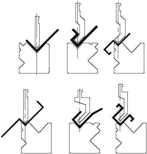
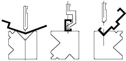
CNC hydraulic sheet metal bending machine is a device used to complete the overall bending and forming of sheet metal. Generally, after one stroke of the slider, it can be bent into a cross-sectional profile of a certain geometric shape. For example, through multiple bending, more complex cross-sectional shapes can be obtained. Therefore, it is widely used in electro mechanical, light industry, agricultural machinery, shipbuilding, automobiles, containers, switches, transformers and aircraft industries. It is an ideal sheet metal bending and forming equipment. CNC hydraulic sheet metal bending machine is assembled from a frame, slider, workbench, oil cylinder, hydraulic proportional servo system, position detection system, CNC system and electrical system. Under three different working conditions, including no-load speed, working speed and return speed, the position of the slider can always be maintained at synchronous speed (parallel to the worktable), and high-precision positioning can be achieved at the end of the stroke.
When the machine is running, the operator steps on the foot switch on the button operation station. Under the control of the numerical control system and the hydraulic servo system, the slider quickly moves from the top dead center to the shifting point at no-load speed (also known as the safety brake). The moving point refers to the conversion point between the no-load speed and the working speed of the slider, and its position can be adjusted), and then the slider continues to move downward at the working speed. When the slider moves to the bottom dead center (also known as the end of the stroke, its position can be adjusted), the positioning of the end of the stroke is completed through the hydraulic servo system and the pressure is maintained. At this time, the plate sandwiched between the upper and lower molds forms a required angle, and then the slider returns to the top dead center.
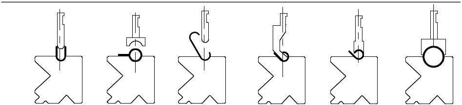
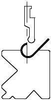
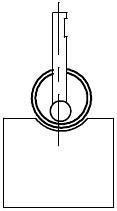
This chapter is attached with a working bending diagram (Fig . 1 Working bending diagram, P5 ) for your reference.
1 Working bending diagram
Figure
2.3.
Use environmental conditions
Ambient temperature: 0 ~ 55 ℃
Ambient humidity: 45 ~ 95 %; no frost
Vibration: 10~55Hz ; 0.7MM ; (maximum 2G )
Shock: 10G ( X , Y , Z )
Altitude: <1000m
Lighting conditions: ≥ 500LUX
Installation environment: no toxic gas; no metal fragments
2.4. Noise of machine tools and measurement methods
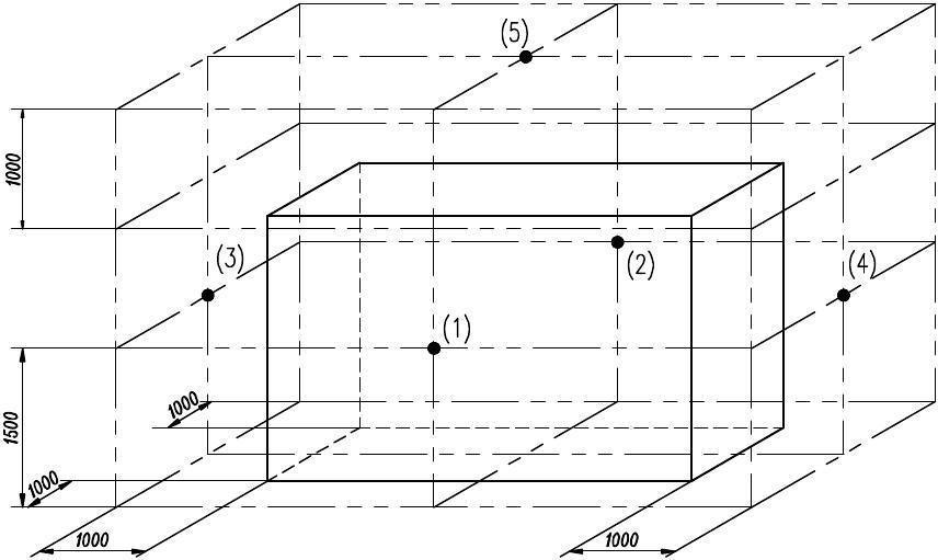
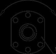
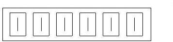
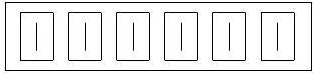
Use a sound level meter to detect the sound pressure level, and measure it at five measuring points (front, rear, left, right, and upper) (Figure 2 Noise measuring point distribution map). The machine tool is required to be in a dry running state without abnormal impact or squealing sounds.
Figure 2 Distribution diagram of noise measurement points
The allowable noise values are shown in the table below ( 1 ).
Table 1 : Noise standards Nominal
2.5. Precautions for use
1 ) The operator must be a trained professional.
2 ) The machine tool must be placed horizontally when installed. Machine tool distortion will affect the performance of the machine tool.
3 ) PPE devices (gloves) are required when maintaining and installing machine tools .
4 ) The machine tool is prohibited from operating under overload or severe eccentric load conditions, otherwise the machine tool may be damaged.
5 ) The materials used on the machine should be harmless.
6 ) If accessories need to be replaced, the model must be consistent with the original model. If you have any questions, please contact our factory ’ s after-sales service department.
2.6. Safety precautions
This manual will mention safety precautions in relevant chapters.
The severity of safety precautions is divided into two categories: "Danger" and "Caution":
Danger !
Risk of death or serious injury due to incorrect handling.
Attention !
Incorrect operation may cause moderate or minor injuries to personnel or damage to items.
3. Structure and working principle
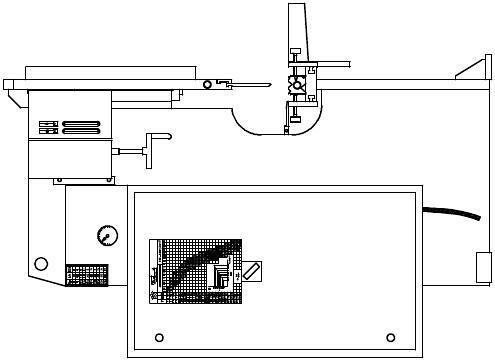
3.1. Machine tool appearance
Figure 3 Machine tool outline drawing
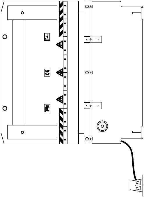
3.2. Machine tool structure
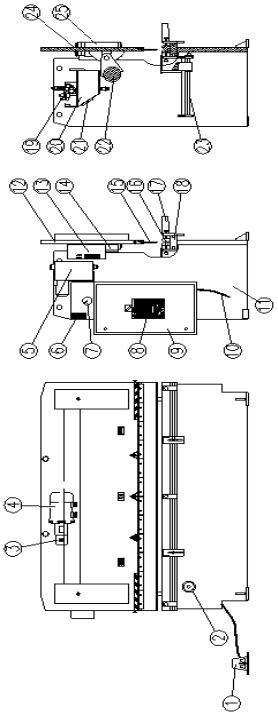
Figure 4 Schematic diagram of machine tool structure
3.3. Introduction to hydraulic system
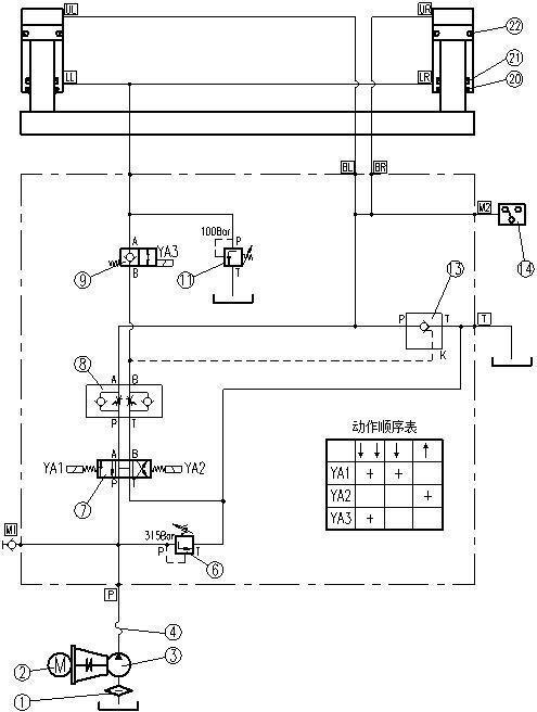
This machine tool adopts a hydraulic transmission system (Fig. 5 Hydraulic Schematic Diagram, P13). Two parallel oil cylinders drive the slider downward. The synchronization of the oil cylinders is ensured by the torsion axis. The hydraulic system adopts a manifold structure, and all hydraulic valves are installed on the manifold (Figure 36 exploded view of the manifold, P47), which improves the reliability and safety of the system and facilitates installation and maintenance.
System analysis:
When the machine tool fast forwards, electromagnets YA1 and YA3 are energized, valve 7 switches to the left working position, and valve 9 switches to the right working position. The pressure oil from the oil pump supplies oil to the upper chambers of the two cylinders at the same time. Since YA3 is powered on, the oil in the lower chambers of the two cylinders passes through valves 9, 8, and 7 and quickly returns to the oil tank. At this time, the dead weight of the slide causes the piston to decline faster than the oil supply speed of the oil pump. Negative pressure is generated. At this time, the hydraulic oil in the tank is sucked into the upper chamber of the oil cylinder through valve 13, and the slider forms a fast forward.
When the slider reaches the speed change point (the signal is sent by the travel switch), YA3 loses power, and valve 9 switches to the left working position. The oil in the lower chamber of the oil chamber generates a back pressure of 100 bar through valve 11, and the negative pressure in the upper chamber of the oil cylinder disappears. 13 valve closes by itself. At this time, the pressure oil from the oil pump enters the upper chamber of the oil cylinder through valves 7 and 8, and the slider forms a working flow.
When the slide reaches the bottom dead center (the signal is sent by the pressure gauge), YA1 loses power, YA2 gains power, valve 7 switches to the right working position, and the pressure oil from the oil pump flows to the lower chambers of the two cylinders through valves 7, 8, and 9. Oil supply, the oil in the upper chamber of the oil cylinder returns to the oil tank through valve 13, and the slider returns. When the
slider returns to the top dead center (the signal is sent by the travel switch), YA2 loses power, valve 7 returns to the middle working position, and the slider stops at the top dead center.
Figure 5 Hydraulic schematic diagram
3.4. Consumable parts
Table 3 Detailed list of wearing parts
4. Transportation and storage
4.1. Precautions for hoisting and transportation
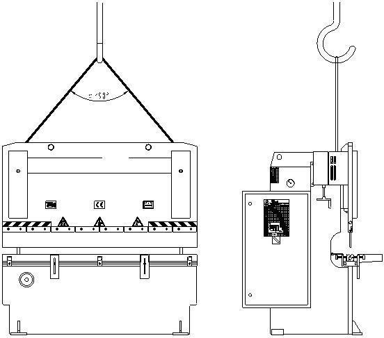
The machine tool is equipped with lifting holes for lifting and installation (Fig. 6 Lifting diagram).
When lifting the machine tool, the weight of the machine tool must be taken into consideration to select appropriate lifting equipment. Any carelessness during lifting may cause the rack to be deformed or damaged.
When transporting machine tools, choose appropriate transport equipment. The machine tool should be bundled firmly and covered tightly to avoid getting wet by rain. Drive slowly when the road is rough to avoid deformation or damage to the rack.
4.2. Storage conditions, storage period and precautions
The host needs to be transported and stored within the temperature range of -25 ~ 55 °C. If the transportation and storage time does not exceed 24 hours , the temperature can be as high as 70 ℃ . Moisture-proof, shock-proof and impact-resistant measures should be taken to avoid damage to the equipment.
5. Installation and adjustment
5.1. Installation of machine tools
Before installing the machine tool, the foundation must be prepared (first pouring) 10 days ago (Figure 9 Foundation Diagram, P17). After the machine tool is in place, the anchor bolts are poured with cement slurry (the second pouring is performed). Except for the four foot plates, the rest of the rack must not be in contact with the ground. After the cement slurry solidifies, perform horizontal adjustment on the machine tool.
5.2. Adjustment of machine tool level
Adjustment of the horizontal level: Place the levels 50mm away from both ends of the workbench (Figure 7), and adjust the foot adjustment screws to ensure that the horizontal (short direction of the workbench) level accuracy is within 0.2/1000mm.
Longitudinal horizontal adjustment: Since the workbench has a convex amount in the long direction (it is a curve with the middle part as the axis of symmetry), the equal height measuring blocks must be placed symmetrically on the workbench, and the inspection ruler must be placed on the equal height measuring blocks. , then place the level on the inspection ruler (Figure 8), adjust the foot adjustment screws to ensure that the longitudinal (longitudinal direction of the workbench) horizontal accuracy is within 0.2/1000mm.
After tightening the anchor bolts at the bottom of the rack, recheck that the accuracy is within 0.2/1000mm.
Precautions:
1) The surface where the level is placed should be free of oil, dust and other dirt.
2) If the longitudinal level is inconvenient to detect, the accuracy of the transverse level can be improved so that the horizontal errors on the left and right sides are in the same direction to ensure that the machine tool is not distorted.
5.3. Hydraulic oil
In the hydraulic system, hydraulic oil is the working medium that transmits power and motion. Whether a hydraulic system can work reliably and effectively depends to a large extent on the hydraulic oil used in the system.
5. 3.1 Cleaning of fuel tank
The hydraulic system of this machine tool has high requirements for the cleanliness of the hydraulic oil, and the cleaning of the oil tank is very important.
Every time the hydraulic oil is replaced, the oil cover must be removed, the bottom of the tank must be wiped with a towel (cotton yarn is not allowed to be wiped), and then clean kerosene or gasoline must be added for cleaning. Due to the limited area of the fuel tank cover, the arm cannot reach the end of the fuel tank. At this time, you can use a clean bamboo pole or wooden stick wrapped in a towel to wipe all corners. Unscrew the oil drain plug or gate valve at the bottom to drain the dirty oil. Use a clean Use a towel to dry the walls and bottom until clean. If necessary, roll flour balls on welds and hard-to-clean areas to pick up dust and debris. After cleaning, install the fuel tank cover.
5.3.2 Selection of hydraulic oil
The grade value of hydraulic oil is equal to the average value of its kinematic viscosity at a temperature of 40 °C.
The higher the working pressure of the hydraulic system, the higher the ambient temperature, and the slower the working speed, the higher the grade of hydraulic oil selected.
ISO for this machine tool VG46# anti-wear hydraulic oil ( the average kinematic viscosity when the temperature is 40°C is 46mm/s ). If the machine tool works below 5°C for a long time, the grade of hydraulic oil selected can be reduced (ISOV G32# ).
It is recommended not to use it at low temperatures (-5°C ). If used below -5°C, the machine tool should be run under no load for a period of time, and an oil heater should be installed on the circuit if necessary.
Under normal operating conditions, the oil temperature should not exceed 70 °
C. In special circumstances, an oil cooler can be installed on the circuit according to actual needs.
5.3.3 Filling of hydraulic oil
The oil used must be clean. Unscrew the nut of the air filter on the fuel tank cover and add oil to the fuel tank through the air filter. If you use a refueling device with a filter, you can open the fuel tank cover and refuel directly into the tank. Observe the oil mark. When the slider stays at the top dead center, the hydraulic oil should occupy 80 to 90% of the space of the oil mark (behind the oil tank) (Figure 10). See the technical parameters for fuel tank capacity (Table 3 Technical Parameters, P1 4).
Liquid level range
Figure 10 oil mark
—If the hydraulic oil used is not clean, it will affect the performance and service life of the system and components.
- After the machine tool has been working for a long time, do not touch the oil tank, oil pump, motor and other parts, as there is a risk of burns.
5.4 Electrical wiring
This machine tool uses three-phase power supply.
Electrical wiring needs to be carried out according to safety regulations.
The voltage should be checked frequently to see if it is normal.
The cross-section of the mains cable must be chosen so that the voltage drop does not exceed the limits stated above.
For power requirements and technical parameters of connecting cables (number of wires and cross-section), please refer to the "Electrical Instructions for Use".
Users need to connect the machine tool ground wire to the flat ground grid to
ensure the safety of personal equipment.
All markings on electrical components are also marked on each electrical diagram. (See "Electrical Instructions for Use").
Please refer to the "Electrical Instructions for Use" for the functions of buttons and indicator lights and the selection of operating methods.
After turning on the power, turn on the machine tool and observe the rotation direction of the oil pump motor. If the direction of rotation is opposite to the direction indicated by the arrow on the oil pump, any two phase lines of the three-phase power supply need to be interchanged.
6. Use and operation
6.1 Installation and adjustment of mold
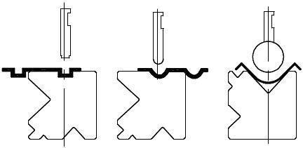
This machine tool can be installed with different types of upper molds (upper mold in Figure 11) and lower molds with different openings (lower mold in Figure 12, P22), which need to be replaced according to the condition of the workpiece.
Pmax=1000kN
R10
Figure 11 Upper mold
(Note: The attached upper and lower mold drawings are for reference only. The actual product shall prevail.)
Figure 12 lower mold
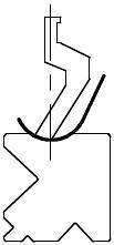
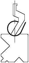
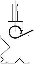
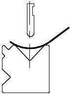
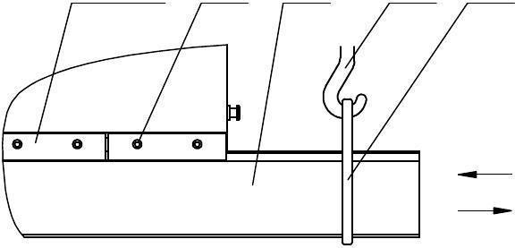
6.1.1 Replacement of upper mold
The mold ordered by the user may be different, but the replacement method is the same. Loosen the screws of the upper mold clamping plate so that the upper mold can slide freely (do not loosen too much to avoid the upper mold falling off and injuring someone), pull out the upper mold from the end, and then insert the required upper mold from the end (picture 1 3), please note that the upper mold stop must be hung on the upper die clamping plate, and tighten the upper mold clamping plate screws (do not crush them).
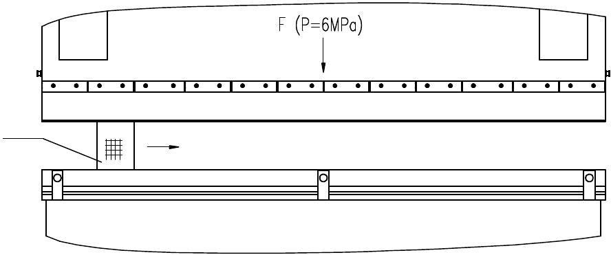
Start the main machine and place a piece of wood between the upper and lower molds (Figure 1 4). Manually operate the slider downward, and press the upper mold from left to right in order to ensure good contact between the upper mold and the slider, and then tighten the screws of the upper mold splint.
Press from left to right
Figure
Square wood
Figure 14
6.1.2 Replacement of lower mold opening
Generally, the opening width of the lower die is 8 to 10 times the thickness of the folded plate.
the adjusting screw c to the end, move the slider down to the bottom dead center, cover the slider and the ejector piles at both ends of the lower mold with the attached ejector chain, then return the slider and lift the lower mold. Turn over to the required surface (Figure 1 5), wipe the workbench and the bottom of the mold, move the slider downward, and carefully place the mold on the workbench.
formwork pile
Ejection chain
formwork pile
Lower mold
Adjustment screw c
Figure 15
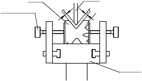
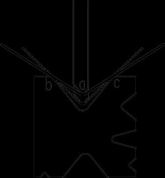
Move the slider down and control it at the appropriate position (there is a certain gap between the upper and lower dies), and check whether the gaps a and b between the upper and lower dies are equal over the entire length. If they are not equal, use the adjusting screw c to adjust the lower die so that the gaps a and b are equal over the entire length (Figure 1 6).
lower mold
Adjustment screw c
upper mold
Figure 16
workbench
Precautions:
1) When changing the mold, adjust the machine tool to the " jogging" working state, and adjust the slider's rapid stroke to the minimum.
2) Check the fixing bolts of the mold regularly.
3) Molds that are not used temporarily should be carefully placed on the shelf next to the machine tool to avoid damaging the mold.
4) When the machine tool is not used for a long time, please lower the slider to the bottom dead center.
Notice!
— When installing the mold and pressing the upper and lower molds, the working pressure of the hydraulic system must be around 6MPa to avoid damaging the mold.
—Each mold has a maximum load capacity, and its maximum load capacity must not be exceeded during use.
Danger!
—The machine tool must not be started without the mold in place. Do not put your hands or other parts of your body into the space between the upper and lower molds at any time. Doing so is very dangerous.
6.2 Adjustment of slider stroke
6.2.1
Top dead center adjustment
The user can adjust the position of the top dead center to control the opening height of the slider as needed.
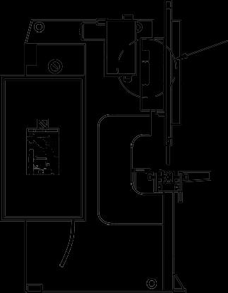
Loosen the top dead center bump block adjustment screw on the left side of the machine tool (Figure 17), move the top dead center bump block to the required position, and then tighten the screw.
6.2.2
Speed change point adjustment
The user can adjust the position of the speed change point as needed to control the position where the slider quickly drives to work.
Loosen the adjustment screw of the speed change point bumper block on the left side of the machine tool (Figure 17), move the speed change point bumper block to the required position, and then tighten the screw.
17
Figure
6.2.3 Bottom dead center adjustment
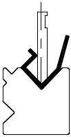
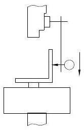
This machine tool adopts three-point free bending and controls the bending angle by controlling the depth of the upper mold entering the V-shaped opening of the lower mold (Figure 18). The deeper the upper mold enters the V-shaped opening of the lower mold, the smaller the bending angle.
Figure 18
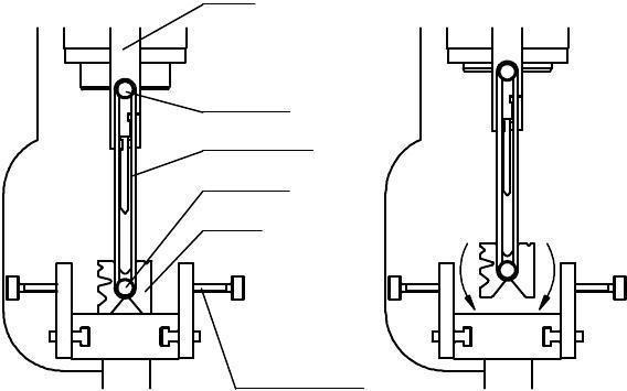
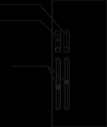
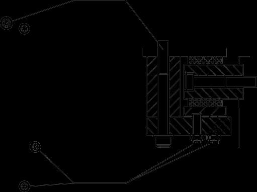
The depth of the upper mold into the lower mold is controlled by mechanical stops. During the downward movement of the slider, when the stopper d presses onto the screw rod e, the slider stops moving and reaches the bottom dead center. When the sprocket g is rotated, the sprocket f is driven by the chain to rotate accordingly, causing the screw rod e to move up and down (Figure 19), so that the position of the bottom dead center of the slider can be adjusted to meet the needs of different bending angles. . The sprocket g is driven by a motor, and the digital display on the boom operating station can display its position. The buttons on the boom operating station can control the mechanical stop to increase at high speed, decrease at high speed, and reduce inching.
Figure 19
6.3 Adjustment of backgauge
The backgauge is used for the rear positioning of sheets. Through the screw drive, the distance from the back gauge to the center of the upper mold can be changed, and the distance value is displayed by the digital display on the operating station. The buttons on the operating station can control the high-speed increase, high-speed decrease, and inching decrease of the back gauge.
The height of the backgauge stop gauge can be adjusted according to the working conditions, and is generally slightly higher than the upper plane of the lower die
20
6.4 Adjustment of front support material
The front support material is used to hold up the folded sheet material for bending, and it can also be used for front positioning.
First adjust the height of the front support material so that the plane of the support material and the upper surface of the lower mold are in the same plane.
The blocking fingers used for front positioning are fixed on the front support material with screws. Loosen the screws, adjust the blocking fingers to the appropriate position, and tighten the screws.
21
Figure
Figure
6.5 Pressure adjustment
The working pressure of the machine tool hydraulic system can be adjusted from zero to the maximum pressure of the hydraulic system. According to the bending working conditions, first determine the bending pressure, and then determine the required pressure of the hydraulic system.
6.5.1
Formula method
The required bending pressure can be calculated by the following formula:
In the formula:
P: Load (kN)
P= 1.42×L×σ b ×S 2
1000×V
L: bending length (mm)
σ b : Material tensile strength (N/mm 2 )
S: Material plate thickness (mm)
V: The opening width of the selected lower mold
Commonly used unit conversion relationships are as follows: 1Kgf≈10N 1t≈10000N=10kN 1MPa≈10Bar
example 1:
Nominal pressure Pf=1350kN;
The maximum pressure of the hydraulic system Py=33.5MPa; Plate thickness S=2mm; Length L=3000mm;
The selected lower mold opening V=8×S=8×2=16mm; The tensile strength of the sheet is σ b =450N/mm 2 .
Required bending pressure F1 = (1.42×3000×450×22)/(1000×16)≈480kN
In fact, this value should be added to 10% of the required bending pressure to get the actual bending pressure:
F2 = F1 +F1×10%=480+480×10%=528kN
The required pressure of the hydraulic system P=(Py × F2)/Pf=(33.5 × 528)/1350≈13MPa
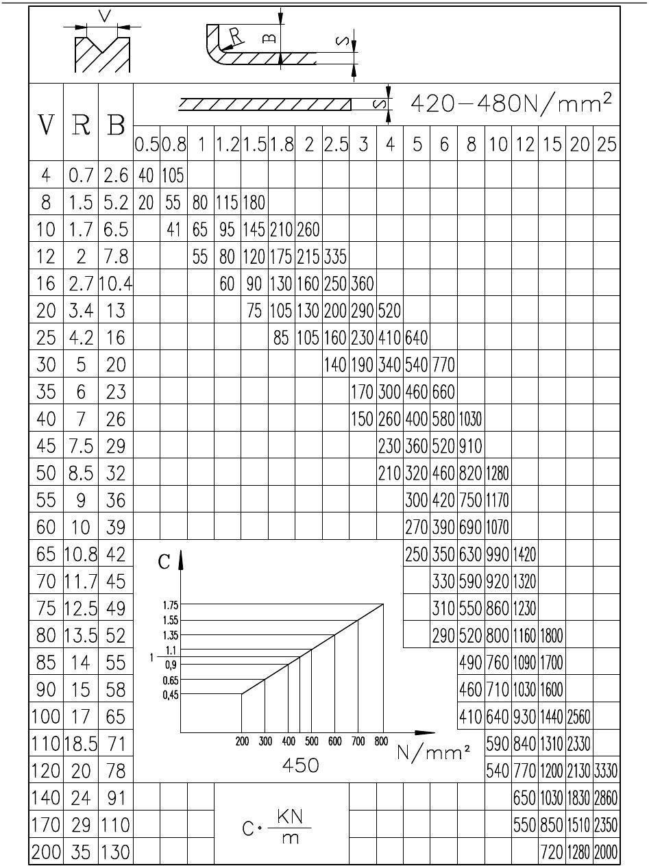
6.5.2 Look-up table method
For the convenience of calculation, the commonly used plate thickness, corresponding opening and bending pressure are drawn into a table (Figure 23 Bending pressure parameter table, P33) for easy query. When the value in the table is σ b =450N/mm 2 , the bending pressure per meter of length, in kN, is equal to the value calculated with the formula. If the plate σ b ≠ 450N/mm 2 , find the coefficient C corresponding to the tensile strength of the material, and then multiply C by the bending pressure found first to obtain the required bending pressure.
Example 2:
Nominal pressure Pf=1350kN;
The maximum pressure of the hydraulic system Py=33.5MPa;
Plate thickness S=2mm;
Length L=3000mm=3m;
The selected lower mold opening V=8×S=8×2=16mm;
The tensile strength of the sheet is σ b =600N/mm 2 .
Look up the table, when σ b =450N/mm 2 , the intersection of the two columns with plate thickness S=2mm and opening V=16mm is the bending pressure per meter length, F 3 =160kN
Check the function chart again, when σ b =600N/mm 2 , C=1.35
Then the required bending pressure F 1 = F 3 ×C×L=160×1.35×3=648kN
In fact, this value should be added to 10% of the required bending pressure to get the actual bending pressure:
F 2 = F 1 +F 1 ×10%=648+648×10%≈713kN
The required pressure of the hydraulic system P=(Py × F 2 )/Pf=(33.5 × 713)/1350≈17.5MPa
(F 1 - calculated bending pressure; F 2 - actual bending pressure; F 3 - bending pressure obtained from table lookup; P - required pressure of hydraulic system)
For the convenience of calculation, after the bending pressure F2 is obtained, the required pressure P of the hydraulic system can be found directly from the pressure conversion plate (Figure 22). (For example: when F2=900kN, P=225Bar=22.5MPa.)
According to the calculated required pressure of the hydraulic system, adjust the knob on the pressure gauge (Figure 22) to control the actual bending pressure.
Figure 22
— Be sure to adjust the working pressure according to calculations. If the working pressure is adjusted too small, the bending work cannot be completed; if the working pressure is adjusted too high, it will cause a waste of energy and affect the service life of the machine tool components.
Figure 23 Bending pressure parameter table
6.6 Instructions on the precision of parts
6.6.1
Effect of plate thickness on accuracy
When bending sheets with uneven thickness, the part will have an angular error. If the plate thickness differs by 0.1mm, when bending a small V-shaped opening, the angle error of the part will be about 2 ° to 3 ° ° ; when bending on a large V-shaped opening, the angle error of the part is less than 2° to 3° .
6.6.2
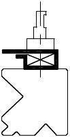
“Protruding” of bending machine
The workbench vertical plate and slide block of the bending machine have two points of contact with the frame. When P force is loaded over the entire length, the following deformation f will occur (Figure 24).
Figure 24
This machine tool uses pre-convexed workbench to offset the deformation of the workbench vertical plate and slider (Figure 25).
Figure 25
6.6.3 Unbalanced load
Offset loading refers to carrying out load work on the left or right side of the slider.
This machine tool generally does not allow off-load bending. Because when bending with eccentric load, the load column is elongated under the action of eccentric load force, so that there is non-parallelism between the workbench and the slider. At the same time, the torsion shaft is in danger of being damaged.
If eccentric load bending is required for processing special parts, the eccentric load force cannot exceed 10% of the bending pressure of the machine tool (Figure 26 eccentric load diagram).
6.6.4 Correction of bending angle error
When the bending angle is less than 110°, it can be corrected according to the formula ΔY=0.0055V×Δα.
(In the formula: ΔY bottom dead center correction value
V Select the opening of the mold Δα angle error value)
If the angle of the inspected part is greater than the drawing requirement, adjust the position of the bottom dead center downward according to the correction value ΔY; otherwise, adjust it upward.
Figure 26 Schematic diagram of eccentric load
7. Adjustment of machine tool accuracy
— During normal use, the following accuracy does not need to be adjusted. When the machine tool is overhauled, you can refer to the following methods to make adjustments. Since experience is very important during the adjustment process, it is not recommended that users make adjustments by themselves. You can contact the manufacturer.
7.1 Synchronization accuracy between slider and workbench
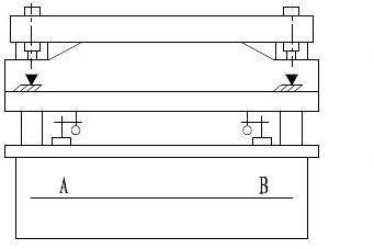
The torsion shaft is a component used to make the left and right cylinders run synchronously. During the movement of the slider, the parallelism between the slider and the workbench is ensured by the torsion axis.
There are bearing pairs at both ends of the torsion shaft installed on the left and right vertical plates. The left side cannot be adjusted, and the right bearing is installed in an adjustable eccentric sleeve. If the flatness error between the horizontal fitting surface of the upper mold on which the slider is installed and the lengthwise direction of the worktable is too large, the eccentric sleeve can be adjusted to reduce the parallelism between the left and right ends of the slider.
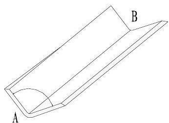
Remove the mold, stop the slider at any position (cannot fall on the mechanical stop), place a dial indicator on the workbench, touch the dial indicator probe to the horizontal joint surface of the upper mold where the slider is installed, and read The errors in the measured values at points A and B are found (Figure 27).
Figure 27
If the error is large, disassemble the gland at the right end of the torsion shaft, insert a cylindrical pin with an appropriate diameter into the optical hole of the eccentric sleeve (Figure 28), and rotate it left and right at a certain angle so that the error in the measurement values at A and B is less than 0.18mm. Then press the gland tightly so that the eccentric sleeve cannot rotate. Repeatedly check the errors of the two measurement values at A and B, and the operation is completed.
28
7.2 Parallelism between the slider and the workbench (equal height)
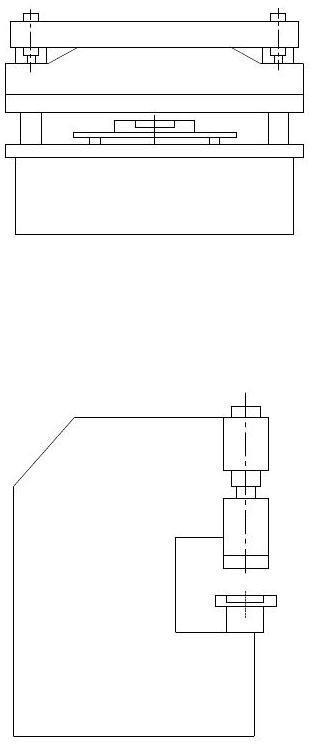
Adjust the screw rod e to the lowest position, place the two equal-height pads on the workbench (Figure 29), and then place the slider on the equal-height pads M and N (a=b), so that the slider is in contact with the two equal-height pads. There are no gaps between equal height gauge blocks. Remove the protective cover, loosen the chain, and rotate the sprocket f on the cylinder until the screw rod e hits the stopper d. Reinstall the chain and the slider can now move up and down.
Figure 29
Figure
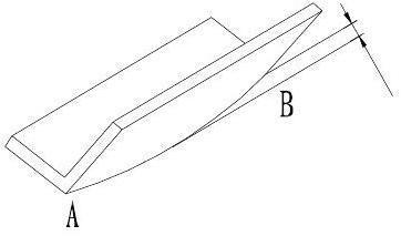
Stop the slider at the bottom dead center. When the system is boosted, use a dial indicator to check whether the equal height values at A and B meet the requirements (Figure 30).
30
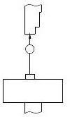
7.3 The verticality of the slider stroke to the worktable
Fix the dial indicator on the slider, place the square on the work surface, and put the dial indicator tip on the measuring surface of the square. When the slider moves downward 100mm, read the verticality error value from the dial indicator (Figure 31).
Figure
Adjust the set screw on the back of the guide rail (Figure 32) to adjust the verticality error of the slider stroke to the worktable. After the adjustment is completed, the gap between the guide rail surfaces is ≤0.05mm, and it cannot be too tight, otherwise the machine tool may not move quickly.
7.4 Back gauge accuracy
Figure 32
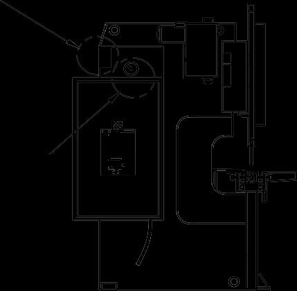
If you find that the backgauge beam is not parallel to the center of the mold during use, you can adjust it as follows.
Loosen the gland on the sliding block (only one of the two is loosened), inside is the nut for the transmission (Fig. 33). Turning the nut left and right can make the corresponding sliding block move forward and backward. Turn the nut to make the retaining beam parallel to the center of the mold, then tighten the nut.
8. Hydraulic system fault analysis and troubleshooting
Table 4 Hydraulic system fault analysis and troubleshooting
serial number Phenomenon Approach
1. Check whether the coupling between the motor and the oil pump has fallen off.
2. Check whether the motor rotation direction is correct
1 Oil pump cannot suck oil
2 No pressure on the system
3 Machine tool has no fast forward
3. Check whether the oil level in the fuel tank is too low
4. Check whether the oil pump suction pipe and filter are blocked
5. Check whether the oil temperature is too low
1. Check whether the pressure of the main relief valve (6) is adjusted to the rated value
2. Check whether the oil pump absorbs oil
1. Check whether the solenoid valve (9) is powered
2. Check whether the double one-way throttle valve (8) is adjusted too small
3. Check whether the machine tool guide rail is adjusted too tight
4. Check whether the torsion shaft is stuck
1. Check whether the YA1 end of the electromagnetic reversing valve (7) is powered
4 No progress in machine tools
5
No return trip for machine tools
6 Machine tool vibration and crawling
7 Fast forward and slow in changing jobs
2. Check whether the pressure of the main relief valve (6) is adjusted to the rated value
3. Check whether valve (13) is reset
1. Check whether the YA2 terminal of the electromagnetic reversing valve (7) is powered
2. Check whether the pressure of the relief valve (11) is adjusted too low
3. Check whether the pressure of the main relief valve (6) is adjusted to the rated value
1. Check whether the gas in the cylinder is exhausted
2. Check whether the oil pump sucks air
3. Check whether the guide rail is adjusted too tight
4. Check whether the double one-way throttle valve is adjusted to the appropriate position
5. Check whether the small slider of the torsion shaft is too tight
6. Check whether the cylinder sealing ring is too tight
1. Check whether the oil suction pipe of the liquid filling valve has fallen off
9. Maintenance and repair
9.1
Lubrication
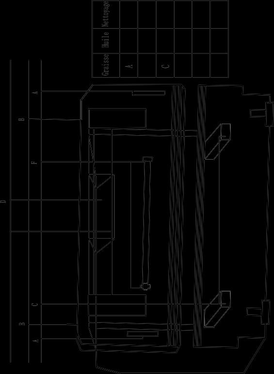
This machine tool minimizes the large number of lubrication points and is easy to lubricate (Fig. 34 Lubrication diagram). Necessary lubrication is an important means to ensure the use of machine tools. The operator must be familiar with all parts of the machine tool that need lubrication and lubricate regularly.
Main lubrication points: fulcrums at both ends of the torsion shaft; guide rails (lubricate every day for a period of time after the test run); two slide blocks of the torsion shaft; back gauge polished rod and screw rod; for exposed wearing parts (no lubrication points), every week Lubricate three times, such as: cylinder, block, nut.
9.2 Hydraulic system
a.Hydraulic oil
Figure 34 Lubrication diagram
Check the oil level of the fuel tank regularly
First oil change after 500 operating hours
From now on, change the oil every 2000 working hours.
b.Filter
The filter element needs to be replaced regularly to avoid affecting the cleanliness of the hydraulic system and causing poor oil suction.
c.Air filter
The air filter is installed on the fuel tank
The machine tool is cleaned for the first time two months after commissioning, and is washed in solvent (gasoline, trichlorethylene)
From now on, clean it regularly every four months.
d. Connection of hydraulic components
If oil leakage occurs, tighten the pipe joint. If this does not help, replace the joint. Sometimes, the high-pressure oil pipe in the hydraulic oil circuit needs to be replaced.
If there is leakage in the valve block, please replace the O-ring or combined sealing ring in time.
9.3 Mechanical parts
Regularly inspect all mechanical parts, chain drives and guide rails.
9.4 Relief valve
This adjustment is very important for the long-term operation of the machine tool.
The normal setting value is equal to the maximum allowable pressure (see Table 2 Technical Parameters, P11).
If our technical service engineers find that the adjustment value of the relief valve exceeds the regulations, our factory will not fulfill any obligations regarding the relevant guarantee.
- Do not adjust the relief valve unless necessary, as it will affect the performance of the machine tool.
1. General requirements:
a. The installation level of the sheet metal bending machine should be adjusted before accuracy inspection. After the machine tool is leveled, the vertical and horizontal directions should not exceed 0.20/1000;
c. Working accuracy should be inspected after full load test;
d. Measuring tools used for accuracy inspection and inspection should comply with the provisions of GB/T 10923;
e. When the actual measured length is less than the length specified in the tolerance, it shall be converted according to the actual measured length, and the conversion result shall be rounded to the number of microns in accordance with GB/T 8170;
f. The limit deviation of the length and width of the test piece is ±2mm, and the limit deviation of the thickness of the test piece is ±0.3mm.
2. Conditions for work accuracy inspection:
a. The length of the specimen; when the length of the workbench is ≤ 2000mm, it is the length of the workbench;
When the workbench length is >2000~3200mm, it is 2000mm; When the workbench length is >3200~5000mm, it is 3000mm; When the workbench length is >5000mm, it is 4000mm;
b. The width of the test piece should not be less than 100mm;
c. Thickness of specimen: 2mm for nominal force ≤1000KN;
Nominal force >1000~2500KN is 3mm;
Nominal force >2500~6300KN is 4mm; Nominal force >6300KN is 6mm;
d. The specimen material is A3 steel plate, its tensile strength σb≤450Mpa;
e. The number of test pieces should be no less than 3;
f. The opening size of the lower die for testing is 8 to 10 times the thickness of the specimen;
g. The test piece should be placed in the middle of the workbench;
h. The bending angle of the specimen is 90° ;
i. Start measuring 100mm from the end of the specimen;
J. The test pieces of thermally cut parts need to be mechanically processed to remove the thermal stress affected area.
Accuracy Inspection Sheet
Item Test items
Leveling of
G0 machine tools
a.Horizontal
b.Longitudinal
Inspection methods and diagrams Allowance mm Actual measure ment
a. Place the equal height measuring blocks symmetrically on the work surface, place the inspection ruler on the equal height measure blocks, then place the level in the middle of the inspection ruler and read the value .
a.Longitudina l 0.20/1000
b. Place the levels in the middle of the table 50 mm away from both ends of the worktable, and read the values.
b.Horizontal 0.20/1000
Flatness of workbench
Accuracy Inspection Sheet
a. Place the level on the work surface in the direction shown in the figure, with the total length at no less than 3 places, and take readings. The error is calculated based on the maximum reading difference.
b. Place the level on the work surface in the direction shown in the figure, with no less than 3 points in total length, and take readings. The error is calculated by the maximum difference in readings.
The parallel surface of the horizontal support that fits the upper mold faces the work surface
a. When the slider stops at the lower limit position, place a dial indicator at position A of the workbench, make the dial indicator probe touch the horizontal supporting surface that is in contact with the upper mold, and read the value. Repeat the above test at B. The error is calculated based on the maximum reading difference between the two dial indicators at AB.
a.Horizontal
G2
b. When the slider stops at the lower limit position,
b.Longitudina l
Place a dial indicator at position A of the workbench, make the dial indicator probe touch the horizontal supporting surface that is in contact with the upper mold, move it back and forth and read the value. Repeat the above test at B. The error is calculated based on the maximum reading difference between the two dial indicators at AB.
Accuracy Inspection Sheet
G3
Test items
Inspection methods and diagrams
Place a square on position A of the workbench, and fasten the dial indicator on the slider so that the dial indicator contact touches the test surface of the square. When the slider reaches its maximum downward stroke, read the value difference. Repeat the above inspection at point B (see serial number 3 for the measurement parts of A and B). The error is calculated based on the larger value between A and B.
P1
Verticality of slider stroke to work surface
Place the universal angle ruler against the outer surface of the bent specimen and measure the degrees in sequence (at least three places per meter). The error is calculated as the difference between the measured maximum and minimum angles and the specified bending angle of 900.
0.10/100
P2
Test piece bending angle Spend
Place the test surface of a 1,000-meter flat ruler against the edge of the bent specimen, and use a feeler gauge to measure the gap δ between the two. The error is calculated based on the maximum gap value within any one meter length.
Test piece bending straightness
0.65/1000
Preface
This manual describes operation of E21 numerical control device and is meant for operators who are instructed for operation of the device. Operator shall read through this manual and know operation requirements before using this device.
Copy right is preserved by ESTUN. It is not allowed to add or delete part or all of the manual content without ESTUN’s consent. Do not use part or all of manual content for the third party’s design.
E21 device provides complete software control and has no mechanical protection device for operator or the tool machine. Therefore, in case of malfunction, machine tool must provide protection device for operator and external part of the machine tool. ESTUN is not responsible for any direct or indirect losses caused by normal or abnormal operation of the device.
ESTUN preserves the right to modifying this manual in the event of function adding or print error.
Chapter 1 Product Overview
1.1 Product introduction
This product is equipped with press brake machine dedicated numerical control device which is applicable to various users. On the basis of ensuring work precision, the cost of numerical control bending machine is reduced significantly.
Features of this product are listed below:
Positioning control of back gauge.
Intelligent positioning control.
Unilateral and bidirectional positioning which eliminates spindle clearance effectively.
Retract functions.
Automatic reference searching.
One-key parameter backup and restore.
Fast position indexing.
40 programs storage space, each program has 25 steps.
Power-off protection.
1.2
Operation panel
Operation panel is shown in Figure 1-1.
Functions of panel keys are described in Table 1-1.
Figure 1-1 Operation panel
Table 1-1 Description of key functions
Key Function description
Delete key: delete all data in input area on left bottom of displayer.
Enter key: confirm the input content. If no content is input, the key has the similar function to direction key
Start key: automatic start-up, top left corner of the key is operation indicator LED. When operation is started, this indicator LED is on.
Stop key: stop operation, top left corner of the key is Stop indicator LED. When initialize normal start-up and no operation, this indicator LED is on.
Left direction key: page forward, cursor remove
Right direction key: page backward, cursor remove
Down direction key: select parameter downward
Function switch: switch over different function pages
Symbolic key: user input symbol, or start diagnosis.
Numeric key: when setting parameter, input value.
Decimal point key: when set up parameter, input decimal point.
Manual movement key: in case of manual adjustment, make adjustment object move in forward direction at low speed.
Manual movement key: in case of manual adjustment, make adjustment object move in backward direction at low speed.
High speed selection key: in case of manual adjustment, press this key and press simultaneously, make adjustment object move in increasing direction at high speed, then press , make adjustment object move in decreasing direction at high speed.
2.1
Chapter 2 Operation Instruction
operation procedure
Figure 2-1 Basic Operational Flow
2.2 Programming
The device has two programming methods, which are single-step programming and multi-step programming. User can set up programming according to actual demand.
2.2.1 Single-step programming
When the parameter X or Y displays ******** on the page, please do not enter the RUN page or Manual page, unless you have reset the teach function of X-axis or Y-axis.
Single-step programming is generally used for processing single step to finish work piece processing. When controller is power on, it will automatically enter single-step program page. Operation steps
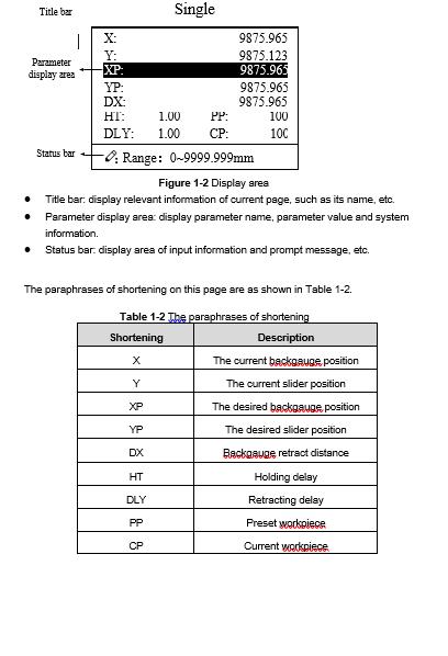
Step 1 After starting up, the device will enter setting up page of single-step program automatically, as shown in Figure 2-2.
Figure 2-2 Single-step program setting page
[Note] Parameter can only be set when Stop indicator is on.
Setting range of singe step parameter is shown in Table 2-1.
Table 2-1 Set up range of singe step parameter
X mm/inch - Current position of X axis, unable to be modified.
Step 2 Press , select parameter which needs to be set up, press numerical key to input program value, press to complete input.
Parameter
Y mm/inch -
XP mm/inch 0~9999.999
Remarks
Current position of Y axis, unable to be modified.
Program position of X axis.
YP mm/inch 0~9999.999 Target position of Y axis.
DX mm/inch 0~9999.999 Retract distance of X axis.
HT s 0~99.99 The time between concession signal valid and end hold time output.
DLY s 0~99.99 In case of single step, delay time for X axis concession.
PP - 0~9999
CP - 0~9999
Number of preset work piece.
Number of current work piece.
Step 3 Press , system will execute according to this program, as shown in Figure 2-3.
X: 9875.965 Y: 9875.123
C: 0 PP: 0 mm
Figure 2-3 Single step operation page
Operation example
On single-step program page, program bending depth to 100.0mm, back gauge position to 80.00mm, retract distance to 50mm, concession waiting time to 2s, holding time to 3s, work piece to 10.
Set up parameter to 50mm, 2s, 3s, 10, 0 by numerical key.
Press , system execute according to this program.
2.2.2 Multi-step programming
When the parameter X or Y displays ******** on the page, please do not enter the RUN page, unless you have reset the teach function of X-axis or Y-axis.
Multi-step program is used for processing single work piece of different processing steps, realize consecutive implementation of multi-steps, and improve processing efficiency.
Operation step
Step 1 Power on, the device displays the single-step parameter page automatically.
Step 2 Press , switch to program manage page, as shown in Figure 2-4.
Figure 2-4 Program management page
Step 3 Press , select program serial number, or input program number directly, such as input “1”.
Step 4 Press , enter multi-step program setting page, as shown in Figure 2-5.
Range:0~25
Figure 2-5 Multi-step program setting page
Step 6 In completion of set up, press , enter step parameter set page, as shown in Figure 2-6. PROGRAM1 1/ 5ST
Step 5 Press , select multi-step programming parameter which requires set up, input setting up value, press , and the set up takes effect.
Figure 2-6 Step parameter set page
Step 7 Press , select step parameter that needs to be set up, input program value, press , and the setup takes effect.
Step 8 Press to switch over between steps. If the current step is the first step, press to enter the last page of step parameter setting; if the current step is the last one, press to enter the first page of step parameter setting. Multi-step parameter setting range is shown in Table 2-3.
Table 2-3 Multi-step parameter setting range
Parameter name Unit Setting range Remarks
Step number of program - 0~25 Setup total processing step number of this program
Parameter name Unit
Preset work piece number - 0~9999
Current work piece number - 0~9999
Number of work piece to be processed, decreasing piece when more than zero; negative increasing count.
Number of finished work piece
Concession delay s 0~99.99 Time between retract signal and concession execution.
Holding time delay s 0~99.99
Time between concessionsignal and end pressurize output
X mm/inch - Current position of X axis, can’t be modified;
Y mm/inch - Current position of Y axis, can’t be modified;
X target position mm/inch 0~9999.999 Program position of X axis;
Y target position mm/inch 0~9999.999 Target position of Y axis; concession distance mm/inch 0~9999.999 Distance of X axis concession;
Repeat times - 1~99 Repeat times required by this step.
Step 9 Press , system will operate according to this program, as shown in Figure 2-7.
X: 5.000
Y: 12345.000
C: 0
PP: 12345 St: 1/ 5
Figure 2-7 Multi-step programming operation page
Operation example
[Background] One work piece requires processing 50 as shown below;
First bend: 50mm;
Second bend: 100mm;
Third bend: the other direction 300mm; [Analysis] according to work piece and technological conditions of machine tool:
First bend: X axis position is 50.0mm; Y axis position is 85.00mm, concession 50mm;
The second bend: X axis position is 100.0mm; Y axis position is 85.00mm, concession 50mm;
The third bend: X axis position is 300.0mm; Y axis position is 85.00mm, concession 50mm; Edit processing program of this work piece on No. 2 program. Operation procedure is shown in Table 2-4.
Table 2-4 Operation steps of multi-step programming example
Operation step Operation
Step 1
Step 2
Step 3
Step 4
Step 5
Step 6
On single step parameter setting page, press to enter program selection page.
Input “2”, press , enter multi-step general parameter setting page of program 2.
Select “Y target position”, input 85, press , and the setup take effect.
Similar to step 7, 8, set up “concession distance” and “repeat times” to 50, 1 respectively.
Press to enter second step setup page of step parameter, the setup method is similar to that of step one.
Press again, to enter third step setup page of step parameter, thesetup method is similar to that of step one and step two.
Press , return to setup page of the first step.
Press , system will operate according to this program.
In completion of multi-step programming, return to start step before launching the system; otherwise, the program will start position processing at current step.
Press left and right direction key to circulate page turning and browsing among all step parameters.
Program can be called and revised again.
In completion of processing all work pieces (50 in the example), system stops automatically. Restart directly will start another round of processing 50 work pieces.
2.3 Parameter setting
User can setup all parameters required for normal operation of the system, including system parameter, X axis parameter and Y axis parameter.
Step 1 On program management page, press to enter programming constant page, as shown in Figure 2-8. On this page, programming constant can be set.
Range of programming constant setup is shown in Table 2-5.
Table 2-5 Range of programming constant setup
Parameter
mm/inch - 0 or 1 0 0: mm, 1: inch
中文/English - 0 or 1 0 0: Chinese, 1: English
Release Time s 0-99.99 0.3
Continue time of unloading output after starting the system.
Pulse Time s 0.000-1.000 0.020 The duration of the pulse signal.
Version - - - Software version information, V refers to version.
1: indicates version number. 0: indicates version level.
Step 2 Input password “1212”, press to enter system parameter setting page, as shown in Figure 2-9. SYS PARA 1/ 1PG
Range: 0~3
Figure 2-9 System parameter setting page
Step up parameter, parameter setup range is shown in Table 2-6.
Table 2-6 System parameter setup range
Parameter Name Unit Range Default Remarks
X-digits - 0~3 1 Decimal point displayed by X axis position parameter
Y-digits - 0~3 2 Decimal point displayed by Y axis position parameter
X-safe mm 0~9999.999 10 X axis keeps low speed in this range
Y-safe mm 0~9999.999 5 Y axis keeps low speed in this range
Step delay s 0~99.99 0.5
Interval between validchange step signal and change step operation executed
X-tea.in mm 0~9999.99 10 In teach enable, input current position of X axis
Y-tea.in mm 0~9999.99 10 In teach enable, input current position of Y axis
Step 3 Press , return to programming constant page. End
2.4 Manual movement
In single-step mode, axis movement can be controlled by pressing key manually. This method helps user to adjust machine tool and work piece.
Step 1 On single step parameter setup page, press or to enter manual page, as shown in Figure 2-10.
Step 2
Step 3
Press , operate at low speed in increasing direction. Press , operate at lowspeed in decreasing direction.
Press , press at the same time, and operate at high speed in increasing direction (this operation is valid only when using frequency converter as the drive).
Press , press at the same time, and operate at high speed in decreasing direction (this operation is valid only when using frequency converter as the drive).
Press return to single step parameter setting page. End
Chapter 3 Alarm
The device can detect internal or external abnormity automatically and send out alarm prompt. Alarm message is available on alarm list.
Step 1 On programming management page, press to enter programming constant page.
Step 2 On programming constant page, press to enter “Alarm history” page to view all alarm history.
As shown in Figure 3-1, the latest 6 alarms, alarm number and causes can be viewed on this page.
ALARM RECORD
A.22 Encoder failure
Figure 3-1 Alarm history page
Alarm history and message is shown in Table 3-1.
Table 3-1 Alarm number and alarm message
Alarm number Alarm name Alarm description
A.01 Count reached prompt Count reaches preset value
A.02 XPos < minimum X position value is less than minimum value
A.03 XPos > maximum X position value is more than maximum value
A.04 YPos < minimum Y position value is less than minimum value
A.05 YPos > maximum Y position value is more than maximum value
A.06 X out of lmt. X position value is out of the limited value.
A.07 Y out of lmt. Y position value is out of the limited value.
A.11 Count reached shut-down
When count reaches preset value, system shut down automatically.
A.12 Beam is not on upper dead point In single step and multistep mode, slider is not on upper dead center.
A.13 X Un-teachIn
A.14 Y Un-teachIn
A.21
Oil pump not started
A.22 Encoder failure
A.25 Drive mode err
A.26 X Stop Err
A.27 Y Stop Err
A.28 X V2 Err
A.29 X V3 Err
A.30 Y V2 Err
A.31 Y V3 Err
A.32 XPos < 0
A.33 YPos < 0
Reset the teach function of X-axis
Reset the teach function of Y-axis
Oil pump signal loss
Encoder voltage is too low.
Neither the drive mode of X-axis and Y-axis is double-frequency converter, please check it.
The backgauge motor is abnormal stop.
The slider motor is abnormal stop.
The speed of backgauge motor is abnormal on the Low-Speed Mode.
The speed of backgauge motor is abnormal on the High-Speed Mode.
The speed of slider motor is abnormal on the Low-Speed Mode.
The speed of slider motor is abnormal on the High-Speed Mode.
X-axis position has exceeded the zero point in manual mode, you should turn back.
Y-axis position has exceeded the zero point in manual mode, you should turn back.
A.41 Parameter storage error -
A.42 Abnormal power failure -
A.43 System self-checking error -
Appendix Common fault and troubleshooting
Fault phenomena
When power on, the device will not display.
Trouble shooting
The electrode of power supply terminal is connected error; please see the information of power nameplate.
Voltage is too low.
Electrical outlet is not connected.
When X axis programming is operating, the back gauge motor does not move, but Y AXIS motor moves.
When program is operating, motor does not move.
Two motors are reversed. Reconnect.
Motor can’t switch from high speed to low speed.
When the device is in multi-step programming, the program can’t change step.
When the device is in multi-step programming, the program can’t count.
When programming is operating, the device loses control.
Check whether mechanical part has been locked or slider returns to upper dead center.
Check whether the motor wiring is connected well.
When programming is operating, the device actual position will not display or change.
Check whether high-lowspeed signal has been sent or motor power is too small.
Check whether the parameter of distance conversion is correct.
Check when slider is on upper dead center, START terminal is connected to +24V or not.
Check when slider is on upper dead center, START terminal is connected to +24V or not.
Check whether encodercable is connected or not.
Check whether the motor-direction wiring is correct (X+、X-、Y+、Y-).
Check whether encoder wiring is correct or encoder cable is connected well.