Skjemategning Animasjon Grafsimulering Visual Designer Internet of Things Kortutlegg www.proteus.no PROTEUS DESIGN Design Suite DESIGN SUITE PROTEUS DESIGN Design Suite DESIGN SUITE Ditt verktøy i arbeid og undervisning
Skjemategning
Mer enn 15 millioner komponenter!
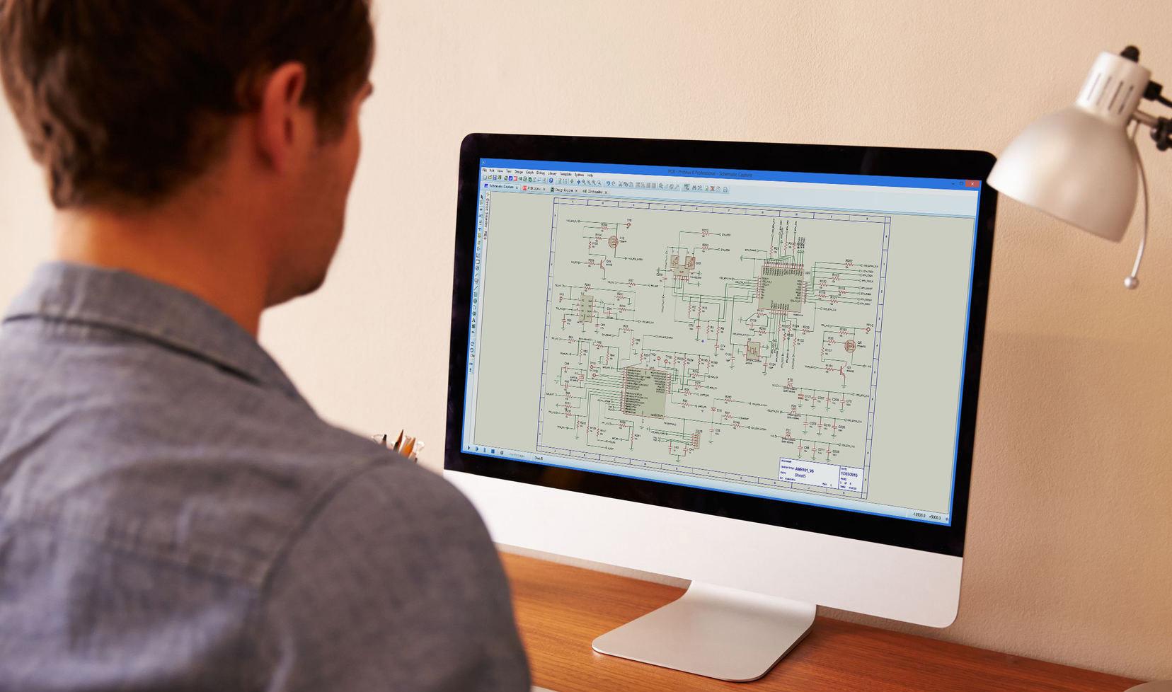
Skjemategnemodulen i Proteus er mye mer enn bare en skjemategnepakke.
Systemet kombinerer et kraftfullt tegnemiljø med full support for BOM (Bill Of Materials) og gjenbruk av lagrede moduler.
Du tegner, kjører animasjoner, simulerer og forbereder kortutlegget i skjemategnemodulen.
Du kan ha flere ark og lage hierarkiske oppsett i samme prosjekt.
Bruk av logiske terminaler gjør skjemaet oversiktlig og forbinder ark og undermoduler.
Gratis opplæringsbøker på norsk på våre nettsider!
www.labcenter.com
OPP L ÆR IN G SKJEMATEGNING – ANIMASJON – SIMULERING PROTEUS DESIGN SUITE Ø VI NG E R SKJEMATEGNING – ANIMASJON – SIMULERING PROTEUS DESIGN SUITE MI N IPR O S J EK T SKJEMATEGNING – SIMULERING – KORTUTLEGG PROTEUS DESIGN SUITE
Animasjon og simulering Analog Animasjon
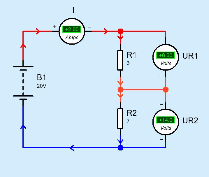
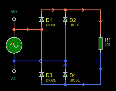
I analog animasjon kan du vise strømretninger som piler i skjemaet.
Du kan også vise spenningspotensialer med valgfrie farger.
Du kan selv velge bakgrunnsfarge, farge på komponenter (fyllfarge og omriss), farge og tykkelse på ledere mm.
www.proteus.no
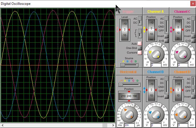
www.labcenter.com AC Amps +3 02 I1 AC Amps +2 99 I2 AC Amps +3 04 I3 L1 L2 L3 k W + 0 . 4 0 P1 k W + 0 . 4 0 P2 k W + 0 . 4 0 P3 k W + 0 . 6 0 P4 k W + 0 . 6 0 P5 3 WATTMETER 2 WATTMETER V1 V3PHASE Analog Animasjon Oscilloskopet har 4 kanaler. Her er det brukt prober med demping 1:10. Måling på trefasekopling
Logiske nivågivere og nivåindikatorer
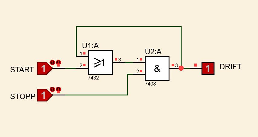
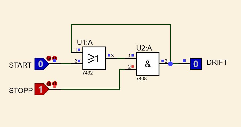
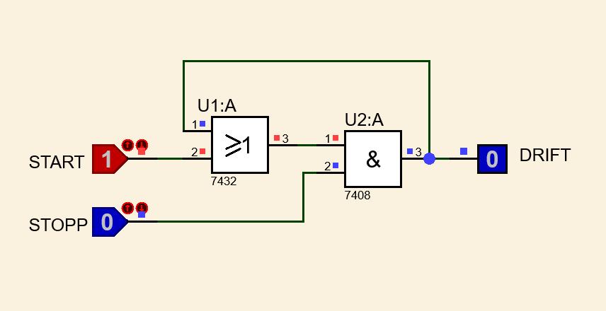
Logisk nivå på inn– og utganger er angitt med en liten firkant. Logisk 1 (Høy), Logisk 0 (Lav), Udefinert nivå (flytende).
Animasjon
simulering
Animasjon 1
og
Digital
2 3
www.proteus.no
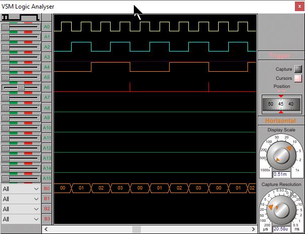
Skjemaet over viser en binærteller som er koplet til en logikkanalysator ved hjelp av terminaler (CLK, QA, QB og QC). Telleren avanserer for negative flanker av klokkepulsene. Tellesekvensen blir 0 – 1 – 2 – 3. Vi har satt LABEL (D0..D2) på utgangene for å kunne kople de til en BUSS. Data på bussen vises med orange farge nederst på analysatorskjermen.
www.labcenter.com
Animasjon
Digital
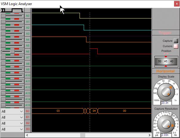
Her ser vi at vi får en
på QC hver gang QB
På
under ser
slik ut: 00 – 01 – 02 – 03
www.labcenter.com
«spiker» (glitch)
går fra HØY til LAV.
bussen
tellesekvensen
QA QB QC CLK
simulering Måling
Logic Analyser
QA QB QC
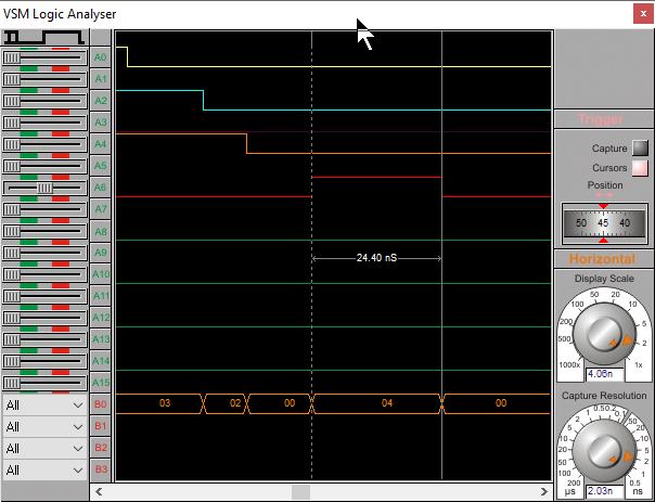
Vi har brukt Cursors på analysatoren for å måle pulsbredden til ca. 24 ns. www.proteus.no
Animasjon og
med
QA QB QC CLK
CLK
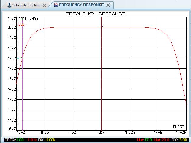
Skjemategning Måling i graf www.labcenter.com R 1 10k R 2 100k +15V -15V Uinn Uut Uut C 1 10uF R 3 1k 3 2 6 4 7 5 1 U 1 AD711 R 4 10k Figuren viser en operasjonsforsterker i inverterende kopling. Sinusgeneratoren Uinn er referanse og proben Uut måler forsterkningen i grafen. F R R u = 2 1 målt forsterkningen der den er 20 dB 17 dB Frekvensrespons
Som i skjemaet, kan du også forstørre i grafer.
AC-Sweep med variabel i grafen
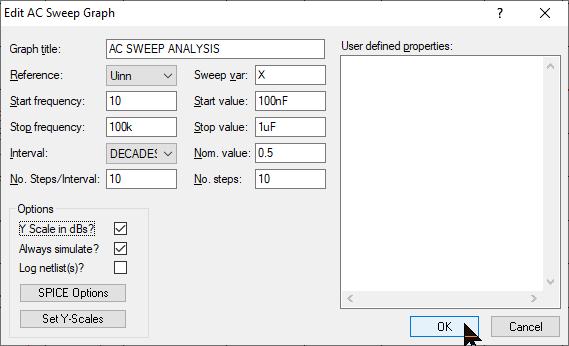
Vi ønsker at nedre grensefrekvens skal være 20 Hz. Hvilken verdi må kondensatoren C1 da ha? Vi endrer verdien fra 10 µF til «X», setter inn en AC Sweep Graph og stiller inn som vist under:
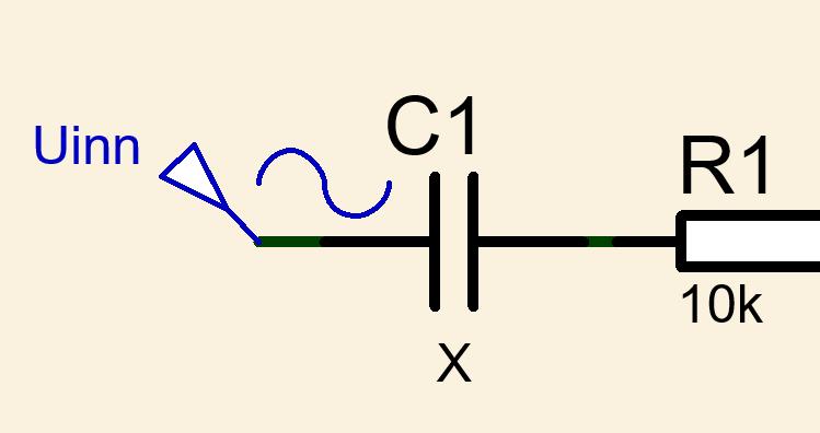
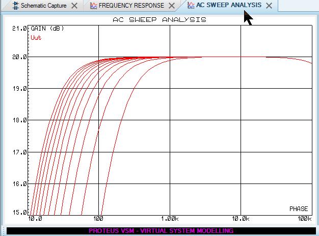
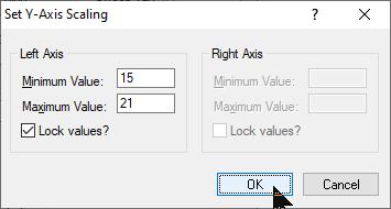
Vi har stilt inn at kondensatoren skal variere mellom 100 nF og Videre har vi satt at Y-skalaen skal vise fra 15 – 21 dB.
Ved å zoome inn og «snappe» kursoren til de forskjellige kurvene i grafen og deretter bevege den til 20 Hz, vil vi få vist forsterkningen og også verdien på kondensatoren i skjæringspunktet:
Her blir det naturlig å velge standardverdien 820 nF.
Analog simulering
1 2 3 4 1 2 3 4
www.proteus.no
www.labcenter.com Visual
S E TU P E ND LO O P E ND RT1 r eadCelcius reading => temp C temp C <tMin NO YES tMin : = temp C temp C >tMax NO YES tMax : = temp C RST BT N() NO YES tMax : = temp C tMin : = temp C tMin : = 100 tMax : = -100 Disp lay Temp E ND Disp lay Temp 100 ms LC D1 setCur sor col : = 0 row : = 0 LC D1 pr int "Temp : ",temp C LC D1 setPlaces places : = 1 MINMA XBT N() NO YES Disp lay Min Max E ND LC D1 setCur sor col : = 0 row : = 0 LC D1 pr int "Min : ",tMin LC D1 setCur sor col : = 0 row : = 1 LC D1 pr int "Max: ",tMax LC D1 clear Disp lay Min Max MINMA XBT N() NO YES LC D1 clear Gratis opplæring på våre nettsider! Enkel programmering av mikrokontrollere med Proteus Visual Designer
Designer for ARDUINO og Rasberry Pi
Visual Designer for ARDUINO og Rasberry Pi PB0/ICP1/CLKO/PCINT0 10
11 PB3/MOSI/OC2A/PCINT3 13 PB2/SS/OC1B/PCINT2 12 PD6/AIN0/OC0A/PCINT22 8 PD5/T1/OC0B/PCINT21 7 PD4/T0/XCK/PCINT20 2 PD3/INT1/OC2B/PCINT19 1 PD2/INT0/PCINT18 28 PD1/TXD/PCINT17 27 PD0/RXD/PCINT16 26 PB4/MISO/PCINT4 14 PB5/SCK/PCINT5 15 PB7/TOSC2/XTAL2/PCINT7 6 PB6/TOSC1/XTAL1/PCINT6 5 PC6/RESET/PCINT14 25 PC5/ADC5/SCL/PCINT13 24 PC4/ADC4/SDA/PCINT12 23 PC3/ADC3/PCINT11 22 PC2/ADC2/PCINT10 21 PC1/ADC1/PCINT9 20 PC0/ADC0/PCINT8 19 AVCC 16 AREF 17 PD7/AIN1/PCINT23 9 ARDUINO UNO IO7 IO6 IO5 IO4 IO3 IO2 IO1 IO0 IO8 IO9 IO10 IO11 IO12 IO13 AD0 AD1 AD2 AD3 AD4 AD5 RESET AREF +5V SS MOSI MISO SCK +5V LED & Reset RXD TXD IO10 IO11 IO12 IO13 IO13 IO0 IO1 AD0 AD1 AD2 AD3 AD4 AD5 IO14 IO15 IO16 IO17 IO18 IO19 RESET Arduino 328 SDA SCL B1 R7 1k D 4 2 1 4 3 Reset Button B2 R8 1k D 5 2 1 4 3 Min-Max Button -tc 26 00 100k 100k Grov e Temperature Sensor A 0 2 1 4 3 VSS SCL VDD SDA JHD-2X16-I2C I 2 C 3 4 1 2 LCD RGB Backlight www.proteus.no
PB1/OC1A/PCINT1
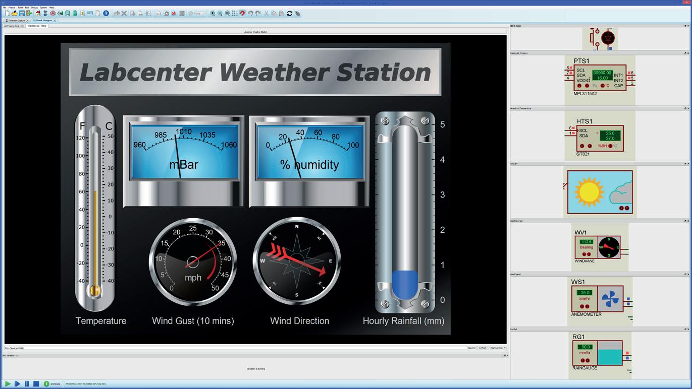
shields, via use the front dials, IoT Visual or Python interface to development tested Proteus executes the real simulate the with as front the press of point hardware, panel the mobile
or tablet and then use Visual Designer or Proteus VSM to program the physical hardware to work with the remote GUI.
IoT Internet of Things Made Easy
IoT Builder removes the necessity for the user to know about HTML, Javascript, Python and the TCP/IP interconnect. All of the complexity of the transport layer and the communication between the processor hardware and the
The front panel is drawn in the panel editor and the logic for the user interface is programmed at a high level with either flowchart blocks (Visual Designer) or C method calls (Proteus VSM). IoT builder is therefore well suited both for teaching the principles of IoT based applications to beginners and also as a rapid prototyping tool for more experienced developers.
IoT Builder is a unique product designed to make it quick and easy to control remote Arduino™ or Raspberry Pi® electronics from a mobile device.
Designed to work with Arduino Yun, ESP8266+Uno or Raspberry Pi 3
Complete IoT Workflow: The IoT Builder workflow is flexible and intuitive.
Start by designing the product hardware on the schematic by adding electronic shields, sensors and breakout boards via the peripheral gallery.
Design your hardware with a library of ready-made shields/hats. Design your front panel with buttons, switches, dials, displays and charts. Link the UI and the hardware with flowchart methods in your firmware. Simulate the entire system and single step debug to find & fix problems. Control the simulation or the real hardware from your phone or tablet.
Then use the controls gallery to create the front panel, adding and placing dials, buttons, charts, etc. in the IoT Builder editor. Finally, use Visual Designer flowchart methods or Arduino C / Raspberry Pi Python code to bind the user interface to the electronics.
At any time during development the entire system can be tested and debugged in the Proteus VSM simulation. This executes the same compiled HEX file as the real hardware and will also simulate the interaction of the front panel with the electronics.
www.labcenter.com
mobile phone
IoT Internet of Things Made Easy
Once everything is working as expected, the firmware and front panel can be deploying to the physical hardware at the press of a button. The final step is to point the target device at the hardware, watch it acquire the front panel over TCP/IP and then control the remote hardware from your mobile phone, tablet or PC.
What can I do with it ?
You can use IoT Builder to design a user interface (switches, buttons, rotary dials, displays etc) for your mobile phone or tablet and then use Visual Designer or Proteus VSM to program the physical hardware to work with the remote GUI.
IoT Builder removes the necessity for the user to know about HTML, Javascript, Python and the TCP/IP interconnect. All of the complexity of the transport layer and the communication between the processor hardware and the remote front panel is abstracted from the users program, leaving the programmer to implement desired functionality. The front panel is drawn in the panel editor and the logic for the user interface is programmed at a high level with either flowchart blocks (Visual Designer) or C method calls (Proteus VSM).
IoT builder is therefore well suited both for teaching the principles of IoT based applications to beginners and also as a rapid prototyping tool for more experienced developers.
How It Works:
Design your hardware with a library of ready-made shields/hats.
• Design your front panel with buttons, switches, dials, displays and charts.
• Link the UI and the hardware with flowchart methods in your firmware.
• Simulate the entire system and single step debug to find & fix problems.
• Control the simulation or the real hardware from your phone or tablet.
www.proteus.no
www.labcenter.com Kortutlegg Prosjektbeskrivelse Vi skal konstruere en audiomikser som består av fire kretser bygd opp med operasjonsforsterkere. Inn 1 Inn 2 Inn 3 Ut 1 Ut 2 Ut 3 Mikser ut Krets 4 Ut 4 Krets 1 Krets 2 Krets 3 Gen 1 Gen 2 Gen 3 Blokkskjema B C D E F G H J K www proteus no TITLE: BY: DATE: PAGE: Mixer Skjema 06 05 2 B Picard 1/1 REV: @REV Ut 4 -15V +15V 3 2 1 8 4 U4:A NE5532 Ut 1 Ut 2 Ut 3 R13 100k 3 2 1 8 4 U1:A NE5532 R2 9k 5 6 7 8 4 U1:B NE5532 Inn 1 R3 10k Ut 1 R1 1k +15V -15V 3 2 1 8 4 U2:A NE5532 R5 4k 5 6 7 8 4 U2:B NE5532 Inn 2 R4 10k Ut 2 R6 1k +15V -15V 3 2 1 8 4 U3:A NE5532 5 6 7 8 4 U3:B NE5532 Inn 3 R7 10k Ut 3 +15V -15V R8 1k R9 5k 78% RV1 5k * R10 100k R11 100k R12 100k Inn 1 Inn 2 Inn 3 Ut 4 1 2 3 4 5 6 7 J1 CONN-SIL7 +15V -15V Ut 1 Ut 2 Ut 3 1 2 3 J2 CONN-SIL3 Krets 1 Krets 2 Krets 4 Krets 3 Skjema Legg merke til bruk av Terminals i skjemaet under. Terminals med
navn er
TERMINALS i Bruk av Terminals gjør skjemaet oversiktlig, og det blir enklere å redigere!
samme
elektrisk forbundet med hver andre.
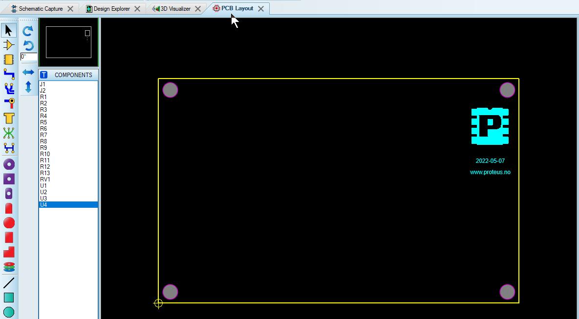
Kortutlegg 0 1 2 3 4 5 6 7 8 9 2022 Fra skjema til kortutlegg Når skjemet er ferdig (og simulert), velger vi fanen PCB Layout Alle komponentene fra skjemaet finner du i COMPONENTS 4 festehull og omrisset av kortet er ferdig. Logo og litt tekst er plassert Plassering av komponenter Du kan bruke verktøyet Auto-placer i Tools-menyen til plassere komponentene innenfor omrisset og deretter «rydde». Ofte plasserer vi komponenter som må stå på en bestemt plass før vi bruker Auto-Placer. 2022-05-07 www proteus no J1 J2 + 1 5 V –1 5 V I n n 1 I n n 2 I n n 3 U t 4 G N D U u t 3 U u t 2 U u t 1 Her er tilkoplinger plassert og tilhørende tekst er plassert på laget Top Silk. www.proteus.no
Skjemategning Kortutlegg
Kortutlegg U 1 U 1 U 1 U 1 J1 + 1 5 V –1 5 V I n n 1 I n n 2 I n n 3 U t 4 G N D J2 U u t 1 U u t 2 U u t 3 U1 R3 R2 R1 U2 R6 R5 R4 U3 R9 R8 R7 RV 1 U 4 R10 R11 R12 R13 2018-09-03-1 www proteus no www.proteus.no
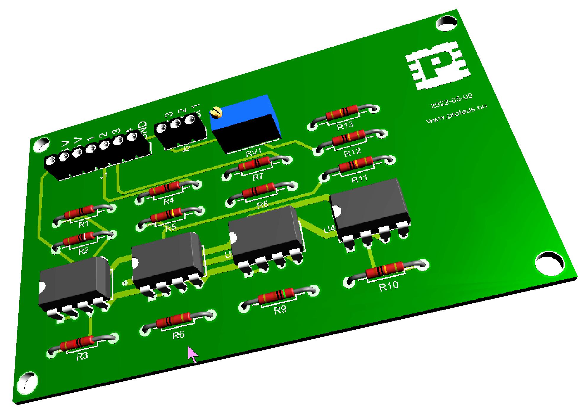
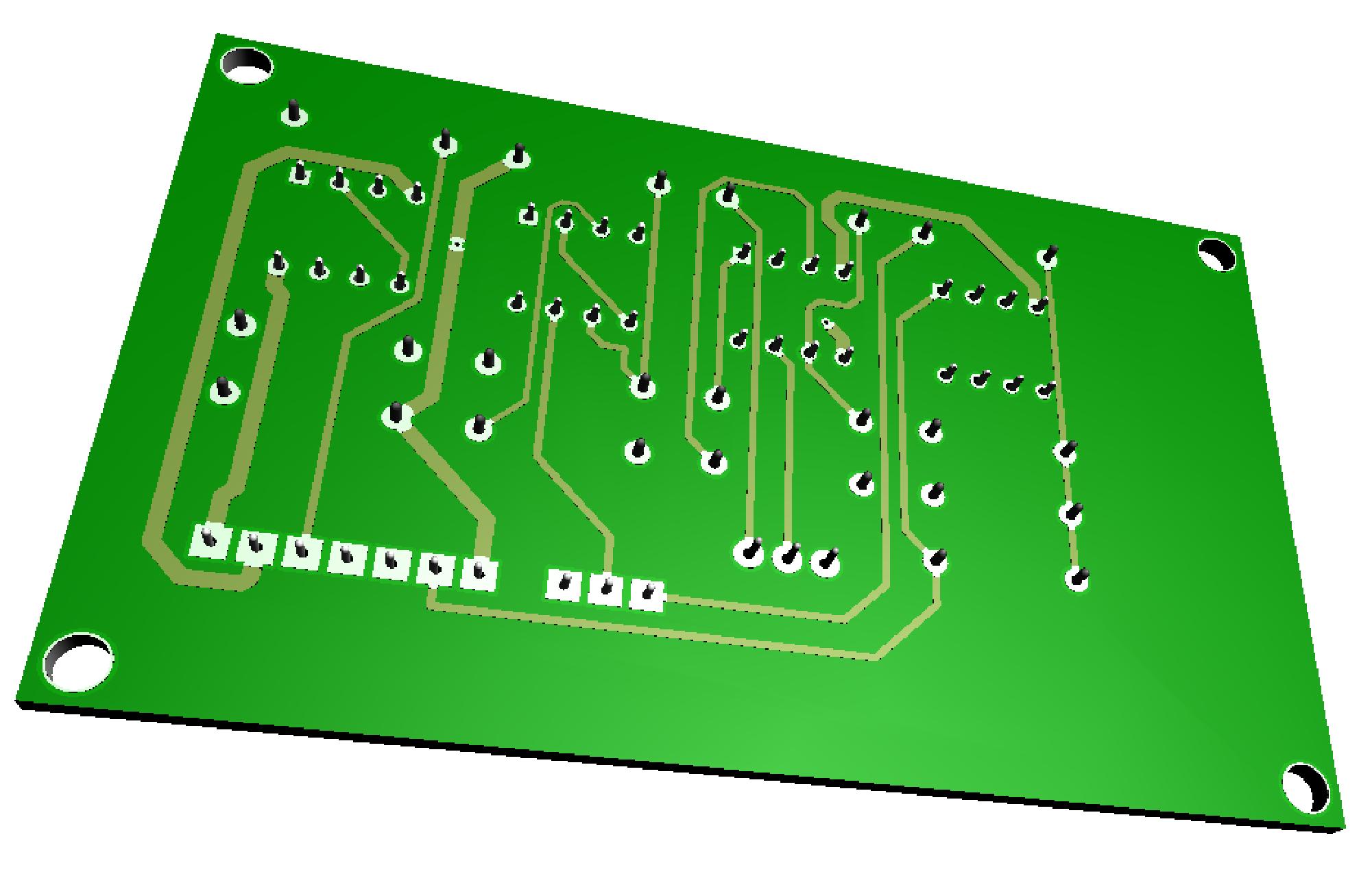
3D Visualizer Med PCB Level 2 eller høyere, kan du betrakte kortet i 3D.
Kortutlegg
www.labcenter.com
Animasjon og simulering
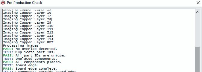
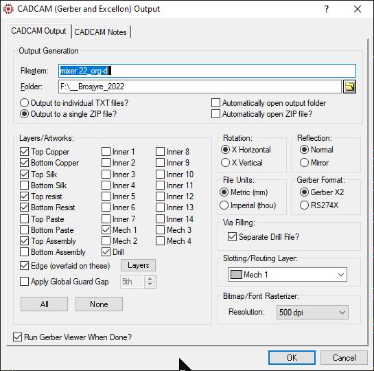
Data til kortfabrikant eller bor/fresemaskin Kun et klikk fra å generere produksjonsdata!
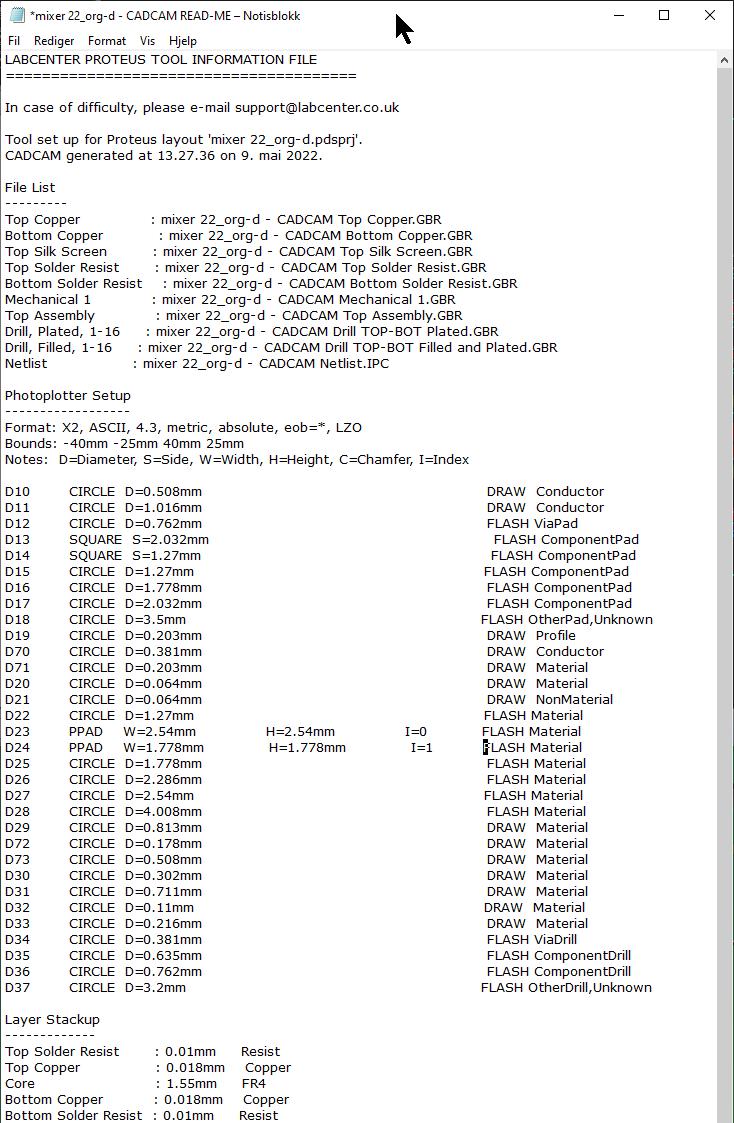
CADCAM www.proteus.no
Kontakt oss
gate
(+47)
450 pedtec
pedtec.no
www.proteus.no
Tordenskjolds
6a N-2821 GJØVIK
909 92
@
https://proteus.no