


All rights reserved. No part of this publication may be reproduced, stored in a retrieval system, or transmitted in any form or by any means (electronic, mechanical, photocopying, recording, or otherwise), without the prior written permission of:
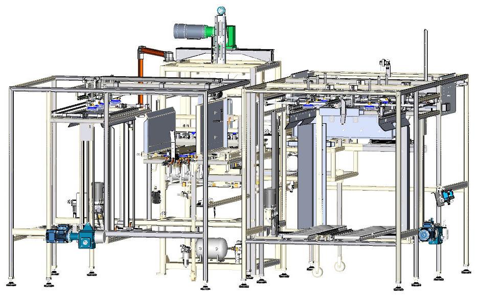
Pearson Packaging Systems
W. 8120 Sunset Highway Spokane, WA 99224
1-800-732-7766 www.pearsonpkg.com
Pearson Packaging Systems strives to ship up-to-date, accurate manuals with our machines. However, continual product improvement does not make this possible. Therefore, this document is provided "as is" at the time of machine shipment.
Please provide your machine serial number whenever ordering parts or referencing information to ensure Pearson Packaging Systems supplies you with the correct parts for your machine.
Pearson Packaging Systems disclaims any liability or responsibility to any person for loss or damages, including but not limited to, the following: expenses, which may arise or result from the use of any information contained in this manual; fines or penalties for the violation of any federal, state, or local regulations.
Pearson Packaging Systems will not be responsible for the unsuccessful operation of any of its products that have been modified in any way by anyone other than an authorized factory representative.
No patent liability is assumed with respect to the use of this information.
Most references to manufacturers or their products are registered trade names and are to be treated accordingly.
Printed in the United States of America
About this Manual................................................................................1-1
Operator Message Boxes
Machine Safety....................................................................................2-1
In This Chapter.
Machine Safety Features.
Machine Safety Precautions
Before You Operate Or Service The Machine For The First Time
At the Beginning Of Each Shift
Lockout/Tagout.
Electrical Safety
Pressurized System Safety
Robot Safety Procedures.
Personal Protective Equipment (PPE)
Energy Shutoff Points.
Emergency Shutdown Procedures
2-13
Machine Overview...............................................................................3-1
In This Chapter.
Machine Overview
Machine Specifications.
3-1
3-1
Machine Operation................... ........................5-1
In This Chapter.
Operator Control Station.
Pre-Run Steps.
Machine Start Up
Air Pressure Switch
Making A Box in Manual Mode.
Performance Checks.
Case Inspection.
Checking Box Construction
Machine Shutdown.
Product Clean Out.
5-9
5-10
5-11
5-13
5-13
5-14
5-15
5-16
Installation........ ..................4-1
In This Chapter.
Receiving the Machine.
Unpacking and Moving the Machine
Leveling the Machine.
Power Connections.
Final Checks.
Changeover Procedures......................................................................6-1
In This Chapter.
Overview.
In This Chapter.
HMI Display Screens
Troubleshooting
In This Chapter.
Preventive Maintenance......................
In This Chapter.
Cleaning Requirements and Precautions
Prevention of Early Oxidation
Maintenance of Areas Displaying Early Oxidation
General Housekeeping
Equipment Maintenance Schedule
General Lubrication
Service......................... ..........11-1
In This Chapter.
Part Replacement
Parts Lists
Part Ordering Procedures
Bill Of Material.
Assembly Drawings
Glossary.......................
11-1
Abbreviations
Glossary
This manual provides instruction on installation, machine safety, operation, preventive maintenance, troubleshooting and service procedures.
The features shown in this manual are st andard. Customer option information is referenced in the Option section at the end of this manual. Please review the Option section, if applicable, before starting up, loading, running or shutting down the machine.
The machine can be either right handed or left handed. The pictures in this manual are for reference and may not reflect the hand of the purchased machine
For the purpose of this manual, photocells, photo eyes, proximity switches, and limit switches are referred to as sensors.
Operator message boxes are used throughout the manual to bring attention to important information, cautions or warnings beneficial for safe and efficient machine operation. In some cases, the operator message boxes reflect the safety labels on the machine.
Operator message boxes include, but are not limited to, the following:
An imminently hazardous situation which, if not avoided, will result in death or serious injury.

Danger! Equipment starts automatically. Lock out/tag out before servicing.
A potentially hazardous situation which, if not avoided, could result in death or serious injury.
Warning! Moving Parts can crush and cut. Do NOT operate with guard removed. Follow lock out procedure before servicing.
Warning! Avoid injury. Do NOT operate machine without all guards in place.
A potentially hazardous situation which, if not avoided, may result in minor or moderate injury.
Pinch Points Any point at which it is possible for a portion of the body to be caught and injured between moving machine or equipment or work piece parts.
Caution A potentially hazardous situation which, if not avoided, may result in property damage (used without the safety alert symbol).
Safety Relates directly to a machine or operator safety issue or concern.
Important Information important to machine operation.
Note Additional relevant information or comments.
Safety is paramount during all phases of design, development, construction, and testing of Pearson Packaging Systems machines
This chapter explains machine safety practices that can help minimize operating hazards and create a safe machine operation and environment. It includes information about:
•Machine Safety Features
•Machine Safety Precautions
•Before You Operate Or Service The Machine For The First Time
•At the Beginning Of Each Shift
•Lockout/Tagout
•Electrical Safety
•Pressurized System Safety
•Robot Safety Procedures
•Personal Protective Equipment (PPE)
•Energy Shutoff Points
•Emergency Shutdown Procedures
1.Flat guards - keep the operator from reaching into unsafe access areas.
Never operate the machine when it is unprotected. Disconnect electrical power and air before removing any guards or shrouds or disabling any other protective device. Pearson Packaging Systems assumes no responsibility or liability for any personnel injury or equipment damage resulting from unsafe machine operation.
2.Guard door safety interlocks - shut down machine operation when doors are opened.
3. Machine Safety Labels - Provide information about potential hazards for persons using, operating, servicing or in proximity of a machine. The labels identify the degree or level of hazard seriousness.
1.Familiarize yourself with your company's safety and lockout/tagout policies and follow them. Prior to adjusting or servicing the machine, make sure you know which lockout/tagout procedure and safety guidelines apply. When in doubt, get answers from your supervisor before you begin.
2.Never reach into, clean, lubricate, adjust, climb on, or work on a moving machine for any reason, even when the machine is only being manually turned over or running at jog speed. ALWAYS follow your company's lockout/tagout policy prior to doing any of the above.
3.Electrical shock or unexpected machine movement can cause serious injury or death. For your safety, follow your company's lockout/tagout policy as required for each task.
4.Moving components can cause serious injury or death. Keep hair, body parts, loose clothing, etc. away from moving components.
5. NEVER deface or remove factory installed safety signs. If a safety sign is illegible, missing, or damaged in any way, report it to your supervisor. She/he will go through the appropriate procedure to obtain a replacement safety sign.
6.Machine mounted blades and knives can cause serious injury, including amputation: keep clear of blades and knives. When supplied, always install/use supplied blade edge and knife guards/shields as stated in the Instruction manual.
7.Hot surfaces/liquids may cause burns. Fluids under pressure can be very hot. Allow ample time for surfaces and system components/fluids to cool before servicing the system. Use an appropriate temperature measuring device (not your hand) to monitor the temperature.
8.If left around the machine area; tools, spare or loose machine parts, and debris can cause serious injury. Use Loctite products (or equivalent) to secure components that are not used as frequent adjusting devices. Keep the machine area clean. When tools and spare machine parts are not in use, store them in the appropriate locations.
9.Lifting heavy components and/or dropping them can cause back injuries, muscle strains, and broken foot bones. Obtain assistance when necessary and use adequate lifting and moving devices properly.
10.Tripping and slipping can cause serious injury. Keep walkways clear. Walking surfaces must be free of liquids (oil, grease, ink, coffee, etc.) and other debris. Equipment surfaces that are touched by hand (operator interface touch screens, control buttons, levers, etc.) must be free of liquids.
11.Disconnect/dump all power sources and dissipate stored energy prior to guards and/or access panels. Install and secure all guards and access panels after completing any adjustments, clearing a jam, and/or servicing the machine. Check affected safety devices to make sure they function properly.
12.The only personnel in the general work area should be those operating/servicing the machine. Restrict all others from the area.
13.Wear protective clothing (hard hat, eye/face shield, gloves, etc.) as necessary. Always wear steel mesh reinforced gloves and arm guards (or equivalent) supplied by your company and use supplied edge guards/shields when handling or working near sharp objects (blades, slitters, knives, etc.).
14.Use the proper tools and equipment for the task being performed. Check the tools routinely to make sure they are in proper working condition.
15.Follow the procedures in the Instruction manual when starting, adjusting, and servicing the machine and when clearing wraps/jams.
16.Check safety devices routinely and replace them at the first indication of defectiveness or failure.
17.Troubleshoot and correct any malfunctions immediately. Call Pearson Packaging Systems Service at 800-732-7766 with any questions.
18.Never blow compressed air toward any person. It is recommended to use protective eye wear when using compressed air.
19.Do not improvise repairs. Pearson Packaging Systems assumes no responsibility or liability for any machines altered in any way or by anyone other than an authorized Pearson representative.
1.Read the instruction manual relevant to the upcoming task before you operate/ adjust/service the machine. If you have questions, get answers before you begin the upcoming task.
2.Prior to clearing wraps/jams, mechanically adjusting, or servicing the machine, lockout/tagout the machine following your company's lockout/tagout policy pertaining to that type of task.
3.Take a walk around the machine, reading all safety signs on the machine and noting the locations of the Emergency Stop devices.
Prior to machine operation/servicing, know the locations of all Emergency Stop buttons/lifelines and the locations of potential hazards.
4. NEVER defeat or remove any of the safety devices. Each one performs a specific function and all of them are provided for your protection.
5. NEVER perform a task that you do not have company authorization to perform. Know which machine related tasks your company has authorized you to perform. Notify the appropriate person to perform all other tasks.
6. NEVER enter the machine area when you are under the influence of alcohol, drugs, or medications that can make you less alert or affect your judgment.
1.Remove rings, watches, necktie, etc. Bind long hair, roll up long sleeves that do not fit snugly to your wrists, tuck in loose shirt tails, and make sure all other clothing fits closely to your body.
2.Review machine operation, performance, and problems with the previous operator/service technician. Make sure all emergency stop features are functional (interlocks, buttons, lifelines, etc.). NEVER operate a machine if any of the emergency stop features are not functioning properly. Make sure all problems are satisfactorily resolved prior to machine start.
3.Make sure the machine is free of wraps/jams. Clear wraps/jams following the jam clearing information in the Instruction manual. Never clear a wrap, jam, or debris from the machine when the machine is in motion.
4.Make sure the machine and the machine area are free of tools and debris.
5.Make sure all machine guards and access panels are installed securely. NEVER operate a machine when any one of the guards or access panels are open, loose, or removed.
6.Make sure the machine is prepared to run in a safe manner by following the machine start information in the Instruction manual.
7.Prior to machine start, be aware of all personnel in the machine area and make sure everyone is clear.
It is the machine purchaser’s responsibility to establish and implement comprehensive lockout/tagout and safety policies for the protection of machine users. Pearson Packaging Systems has established the following guidelines for the lockout/ tagout policy to assist you in this effort.
1.Shut down the machine using the normal stop control.
2.Notify all personnel in the area that you will be placing a lockout/tagout on the machine and the reason for the lockout/tagout.
3.Turn off and lock out the main power Disconnect switch.
4.Turn off and lock out the main air supply valve prior to working on any pneumatic systems.
5.Lockout the energy isolating devices with an assigned individual lock. Hang “Do Not Start” tags on the start controls.
6.The “Do Not Start” tags CANNOT be used as the only means of lockout, they must be used in conjunction with approved locks and/or other lockout devices.
7.Clear personnel from the machine area and perform checks (using appropriate energy measuring devices) to ensure that the circuit/machine is de-energized.
8.After performing the checks, double check that the circuit/machine is de-energized by trying to operate it using the controls (screen template, pushbutton, switch, etc.) related to that machine function. The circuit/machine is locked out if the initiated function/component movement DOES NOT occur.
This machine uses electricity of sufficient voltage to cause serious injury or death if mishandled.
Note: Drive settings have been adjusted and set at Pearson Packaging Systems. Consult the machine documentation for drive settings.
1.Permit only trained/qualified electrical technicians to work on electrical components, regardless of whether the components are live or dead.
2.Know the location of all electrical disconnects, shutoffs, and similar devices and know what each disables. Refer to the machine assembly drawings for this information.
3.Keep electrical areas (and the machine in general) dry. Never work on electrical components while standing on or near wet surfaces.
4.Always assume a circuit/component is live until proven dead by proper testing. Always test circuits/components with appropriate test equipment (not your fingers).
5.Always be on the lookout for electrical wires and components that are frayed, cut, loose, broken, or exposed. Repair/replace such wires and components before machine power is restored and the machine is operated.
6.Prior to machine operation, make sure wires, motor plugs, cables and similar devices are securely connected.
7.Never remove a lockout device or “Do Not Start” tag unless you were the one who put it there. Notify everyone in the machine area when you remove your lockout/tagout that power is going to be restored to the machine.
The machine is equipped with a pneumatic system to move and control machine components. These systems are typically under pressures high enough to cause serious injury if mishandled.
1.Obtain company training/authorization prior to servicing a pressurized system.
2.Use the proper tools and equipment for the task being performed. Check the tools routinely to make sure they are in proper condition.
3.Fluids under pressure can be very hot. Allow ample time for the system fluid/ components to cool before servicing the system. Use an appropriate temperature measuring device (not your hand) to monitor the temperature.
4.Lockout/tagout the machine and relieve stored energy in the pressurized system following your company’s lockout/tagout policy prior to servicing/disassembling any portion of the system.
5.Never operate or pressurize a system that has worn/damaged components. Never adjust pressurized systems beyond the recommended setting/range. The Machine Setting section of the Instruction manual provides base pressure settings for all pressurized systems that are not run at line pressure. These base settings could require minimal adjustment to best suit actual running conditions. Do not increase/decrease machine stopping times without consulting Pearson Packaging Systems.
Observe the following safety procedures if the system is equipped with a robot. The ANSI robot standards (RIA R15.06-2012) list the following procedures for entering a robot cell.
Personnel entering the robot cell when drive power is available shall have total control of the robot. This shall be accomplished by the following:
1.Control of the robot shall be removed from the automatic mode.
2.Single point of control of the robot system shall be accomplished using PanelView.
3.Additional personnel within the safeguarded space must be furnished with an enabling device.
4.All robot emergency stop devices shall remain functional.
5.To restore automatic operation, the following shall be required:
a.All personnel must exit the safeguarded space.
b.Visual inspection of the “safeguarded space” to assure all personnel are clear.
c.Audible “Robot Clear” announced.
d.Restore safeguards required for automatic operation.
e.Initiate deliberate startup procedure.
f.In addition, do not walk under the robot tool with cargo; a drop hazard exits.
6.Refer to the Robot manual for additional safety instructions.
1.Always wear your company's approved PPE while operating the machine to minimize your injury risk.
2.For machines using hot melt adhesive heed the following warnings.
Hazardous vapors! Before processing any polyurethane reactive (PUR) hot melt or solvent-based material through a compatible Nordson melter, read and comply with the material’s MSDS. Ensure that the material’s processing temperature and flashpoints will not be exceeded and that all requirements for safe handling, ventilation, first aid, and personal protective equipment are met. Failure to comply with the MSDS requirements can cause personal injury, including death.
Molten Material! Wear eye and face protection, clothing that protects exposed skin, and heat-protective gloves when servicing equipment that contains molten hot melt. Even when solidified, hot melt can still cause burns. Failure to wear appropriate personal protective equipment can result in personal injury.
Hot surfaces! Avoid contact with the hot metal surfaces of guns, hoses, and certain components of the melter. If contact cannot be avoided, wear heat-protective gloves and clothing when working around heated equipment. Failure to avoid contact with hot metal surfaces can result in personal injury. The machine will not start unless all guard doors are closed.
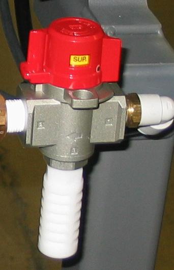
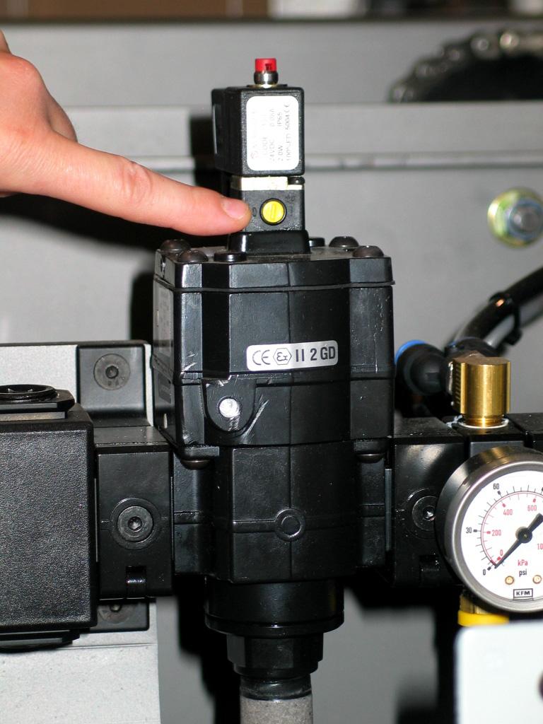
This machine is equipped with a Pneumatic Energy Isolating Valve. The isolating valve isolates the equipment from the main air source and exhausts any air remaining in the machine.
Note: Two styles of Pneumatic Energy Isolating Valves are used on Pearson equipment. Identify the style on your machine and follow the instructions provided.
1.To dump air from the system, rotate the red head of the valve to the exhaust position.
a.The yellow window will read EXH.
2.Follow your company's lock out/tag out procedures.
3.To return air to the system, rotate the red head of the valve to the open position.
a.The yellow window will read SUP.
4.Manual air override button is provided for inspection and troubleshooting the pneumatic system. It must be deactivated in normal run mode (gauge pressure will read zero).
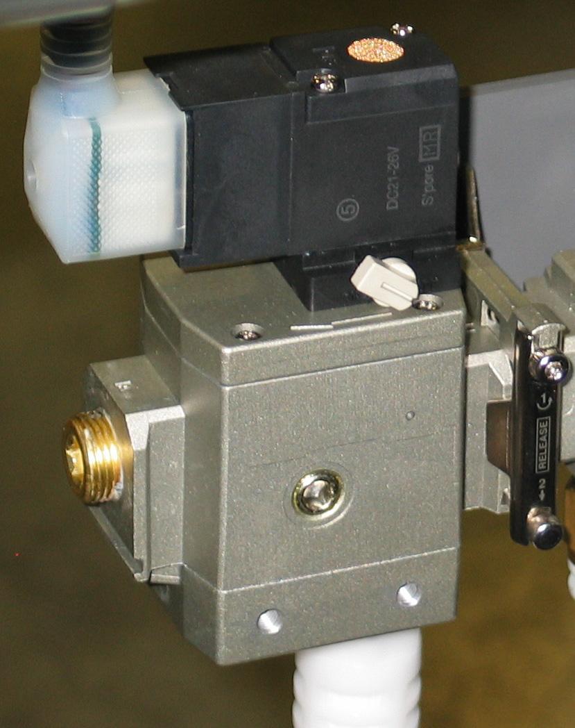
1.To dump air from the system, push the yellow slide plate to the closed position.
a.The slide plate will read Closed.
2.Follow your company's lock out/tag out procedures.
3.To return air to the system, push the yellow slide plate to the open position.
a.The slide plate will read Open.
4.Manual air override button is provided for inspection and troubleshooting the pneumatic system. It must be deactivated in normal run mode (gauge pressure will read zero).
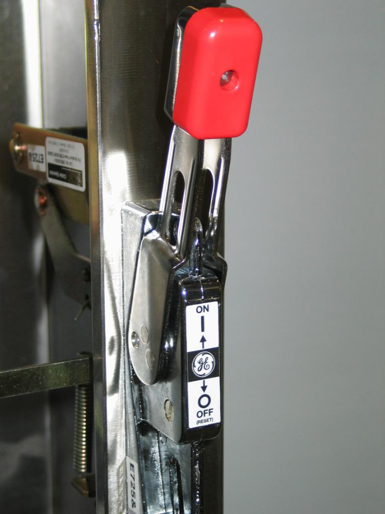
Electrical Disconnect
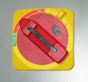
Note: The Electrical Disconnect is located on the front of the Main Electrical Panel.
1.To disconnect power from the Main Electrical Panel, turn the Electrical Disconnect to the OFF position.
2.Follow your company's lock out/tag out procedures.
3.To reconnect power, turn the Electrical Disconnect to the ON position.
1.In the event of an emergency, press the E-stop button, and follow your company's Emergency Shutdown Procedures.

This Page Intentionally Left Blank
Operations Manual BF30-2AS Bliss Former
This chapter provides a machine overview and machine specifications.
Machine Overview
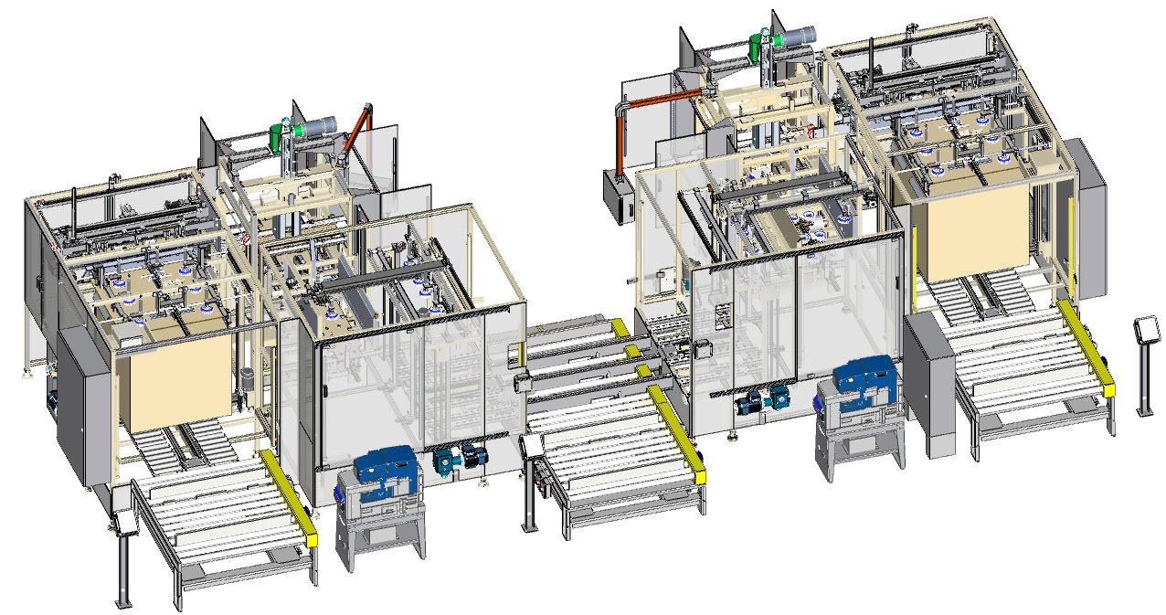
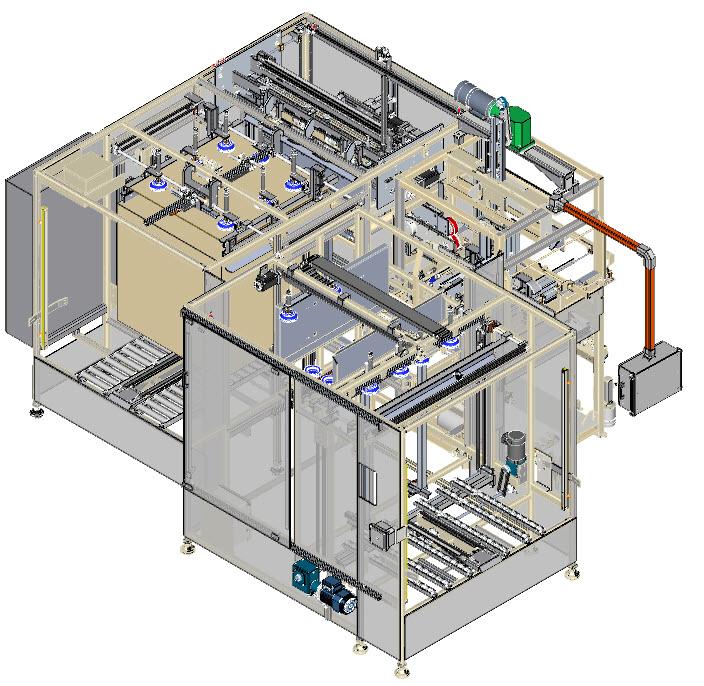
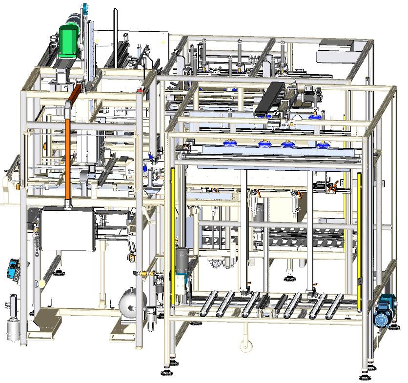
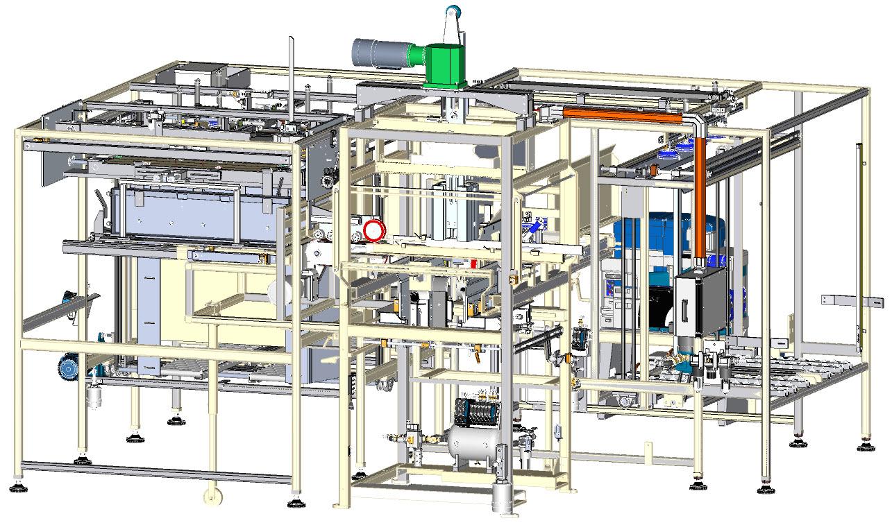
The Pearson BF30-2AS (A) is a 2-Piece Bliss Former with body wrap and insert autoloader and end panel insert blank slitter.
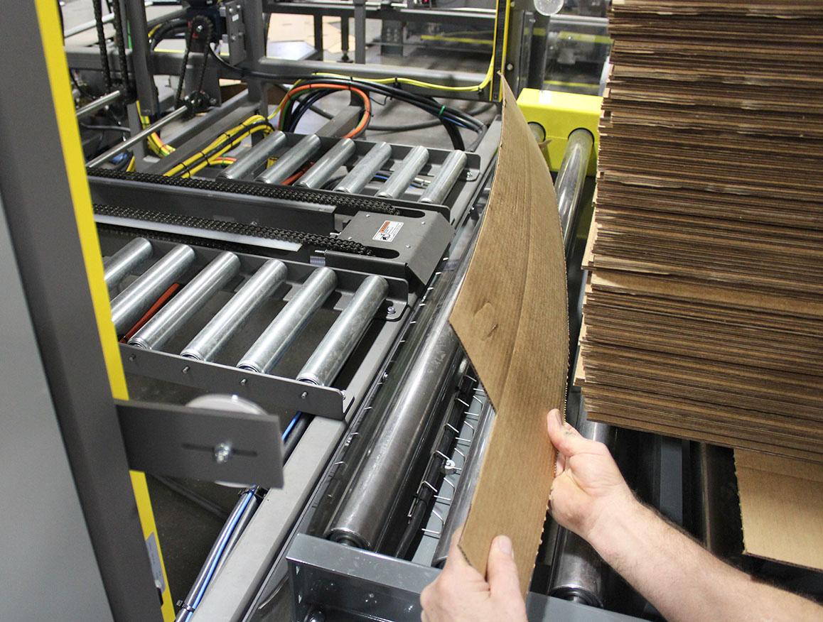
Pallets of body wrap blanks are loaded onto the material infeed conveyor (B) and the operator removes the dunnage. They are then are transported to a lift station (C) where a sheet feeder transfers the blanks into the body wrap hopper.
Pallets of end panel blanks are loaded onto a material infeed conveyor (D) for each BF30-2AS and the operator removes the dunnage. They are transported to a lift station (E) and elevated to a servo driven slitter (F) which cuts the corrugated sheets to the programmed width and loads the end panel insert hopper.
The case is formed from the body wrap and end panel insert with external flanges, resulting in a smooth inside and a solid one piece bottom.
Machine Specifications
•24 Volt D.C. Controls
•Maximum reliability with all production proven machine components
•Quick changeover features
•Vacuum assist feed systems
•Positive glue compression
•Welded tubular steel frame
•Belt Drive Feed System
•UL approved electrical control panel
•Allen Bradley Panelview 1000 Plus
Case Size Ranges
Please consult Pearson Packaging Systems regarding case size ranges.
Standard Electrical Specifications
Please see machine-specific electrical schematic.
Machine Footprint
Please see machine-specific floor plan.
Programmable Logic Controller
Allen Bradley CompactLogix
This chapter gives the steps, procedures and equipment necessary to operate the BF30-2AS H-Bliss Former.
Note: The Infeed end of the machine (A) is the “rear,” the discharge end (B) is the “front.” Facing the machine in the direction of flow (C), the “operator’s right” (D) is to the right, the “operator’s left” (E) is to the left.
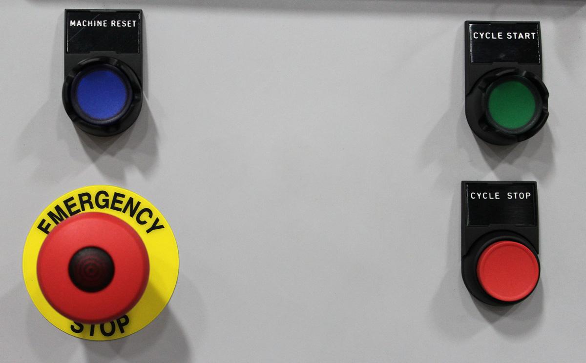
The Operator Control Station has the controls that start or stop machine operation in the event of an emergency.
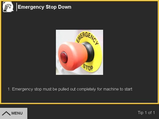
A controlled Emergency Stop button (E-stop) (A) is located on the right of the Operator Control Station. When the E-Stop button is pushed, power to the machine is disrupted and the machine immediately stops. The E-stop button must be pulled back out before the machine can be restarted.
The blue Machine Reset button (B) must be pressed when it is illuminated to reset the safety relays before the machine can be restarted. A reset is required whenever an E-stop has been pressed or a guard door has been opened. After it is pushed, the air dump comes on, and the Cycle Start begins to flash when the machine is ready to start.
The green Cycle Start button (C) starts the machine. It flashes when the machine is in standby mode and ready to start, and is on solid when the machine is running.
The red Cycle Stop button (D) causes the machine to come to a controlled stop. The machine cycles twice with the vacuum off before coming to a complete stop to completes any cases in process.
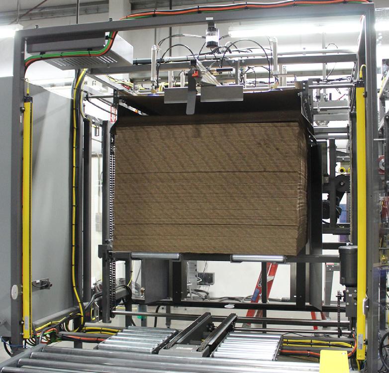
The end panel sheet and body wrap elevators are open and guarded by light curtains (A). A beacon light (B) indicates when the light curtain is muted to allow stacks of material to pass through.
The Light Curtain Override selector switch allows the operator to reset the light curtain if it is blocked when an E-Stop is pressed or the machine faults and shuts down.
1.To reset the light curtain turn and hold the Light Curtain Override switch.
2.Press the Light Curtain Reset when it starts flashing.
3.Press the Machine Reset button.
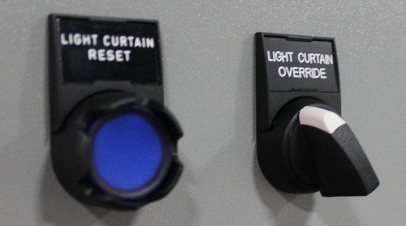
4.Go to the Manual functions in the HMI and jog the material out of the light curtain. See the HMI Chapter for more information.
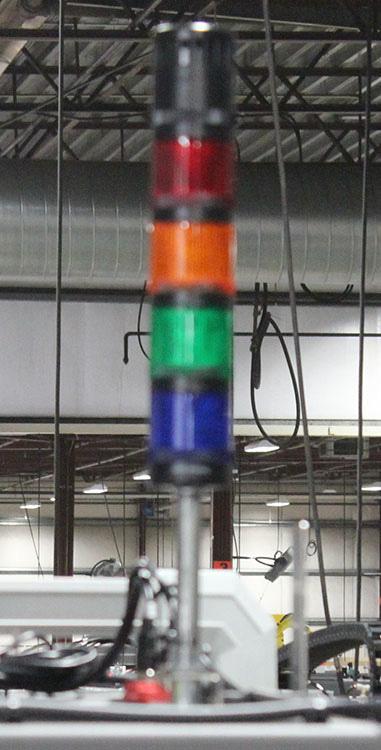
A four light beacon with a warning horn is located above the operator station.
RedFlashing: Alarm
Solid: E-Stop or door open
AmberFlashing: Hoppers low or material conveyor issue
GreenSolid: Machine running
BlueFlashing: Discharge high level
1.When the Machine Reset button is pushed, the horn will cycle on an off for three seconds before the Cycle Start button begins flashing.
2.When there is an alarm, or low air pressure, the horn will cycle on an off for three seconds. See the HMI for more information.
3.If air is detected when the machine starts the horn will sound continuously. It will not turn off after three seconds.
Note: Under no circumstances should you enter the machine if the system is pressurized.
The material handling infeed system has a system Emergency Stop button and System Reset button located on the electrical panel (A). Each of the three material infeed conveyors has a pedestal (B) with controls for that specific conveyor.
A controlled Emergency Stop button (E-stop) (C) is located on the electrical panel and on each of the control pedestals. When the E-Stop button is pushed, power to the material handling infeed conveyors is disrupted and the machine immediately stops. The E-stop button must be pulled back out before the machine can be restarted.
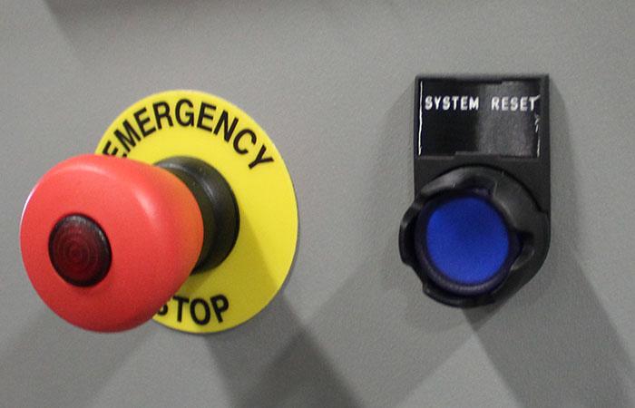
The blue System Reset button (D) must be pressed when it is illuminated to reset the safety relays before the material handling infeed conveyor system can be restarted. A reset is required whenever a system Estop has been pressed. After it is pushed, conveyor reset buttons on the pedestals come on begins to flash when the machine is ready to start.
A controlled Emergency Stop button (E-stop) (A) is located on the electrical panel and on each of the control pedestals. When the EStop button is pushed, power to the material handling infeed conveyors is disrupted and the machine immediately stops. The E-stop button must be pulled back out before the machine can be restarted.
The blue System Reset indicator (B) lights when the System Reset button is required. The system must be reset before the individual conveyor can be reset.
The rest of the buttons on the conveyor pedestal only control the specific infeed conveyor they are located near.
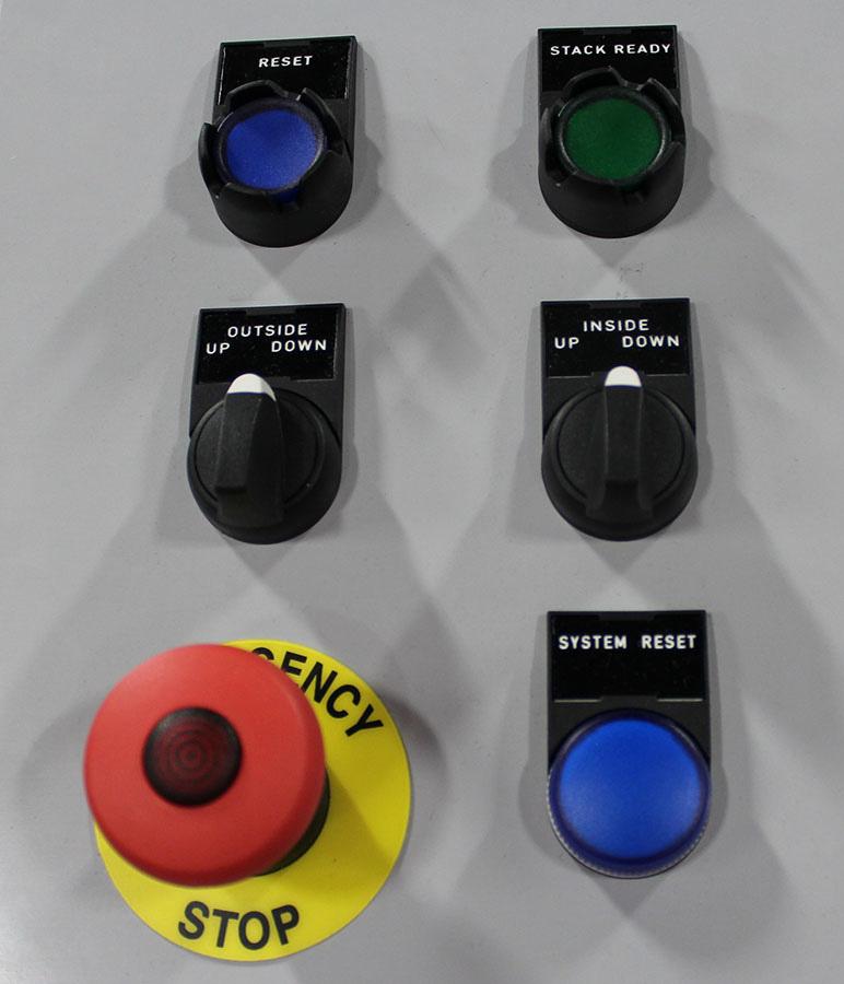
The blue Reset button (C) must be pressed when it is illuminated to reset the safety relays before the conveyor can be restarted.
The green Stack Ready button (D) is pressed after dunnage has been removed and the stack of material is ready to feed into the system.
The Inside Up/Down switch (E) raises and lowers the inside rails on the infeed conveyor.
The Outside Up/Down switch (F) raises and lowers the outside rails on the infeed conveyor.
1.Allow the hot melt adhesive system time to come up to temperature.
a.Check the level of hot melt adhesive and the temperature.
b.Ensure the hot melt adhesive is flowing freely.
Hazardous vapors! Before processing any polyurethane reactive (PUR) hot melt or solvent-based material through a compatible Nordson melter, read and comply with the material's MSDS. Ensure that the material's processing temperature and flashpoints will not be exceeded and that all requirements for safe handling, ventilation, first aid, and personal protective equipment are met. Failure to comply with the MSDS requirements can cause personal injury, including death.
Molten Material! Wear eye and face protection, clothing that protects exposed skin, and heat-protective gloves when servicing equipment that contains molten hot melt. Even when solidified, hot melt can still cause burns. Failure to wear appropriate personal protective equipment can result in personal injury.
Hot surfaces! Avoid contact with the hot metal surfaces of guns, hoses, and certain components of the melter. If contact can not be avoided, wear heat-protective gloves and clothing when working around heated equipment. Failure to avoid contact with hot metal surfaces can result in personal injury. The machine will not start unless all guard doors are closed.
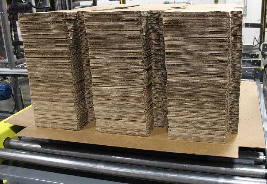
Load corrugated material onto the end panel and body wrap material infeed conveyors as follows:
1.Make sure the blue Reset button is not illuminated.
2.Place a stack of material on the conveyor.
3.Use Inside Up/Down switch to raise the inside dunnage rails to support the stack.
4.Remove the fork truck or lift.
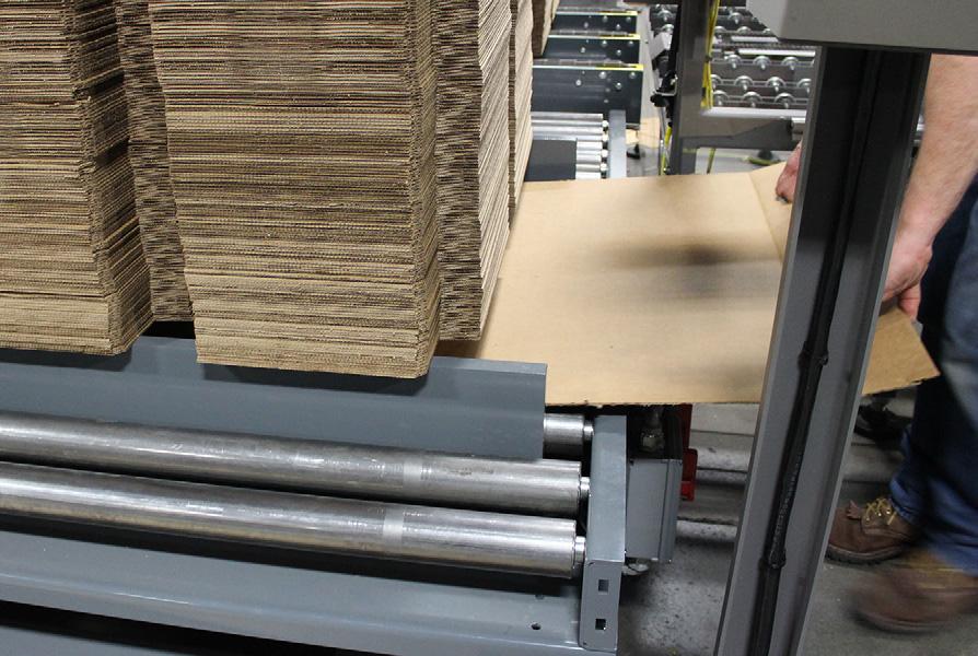
5.Tear off the end dunnage (A) at the scoreline on both sides and remove it.
Note: Be careful not to break the plane of the light curtain (B) when removing the end dunnage closest to the entry point on the end panel infeed conveyors.
6.Lower the inside rails and raise the outside rails (C). This can be done at the same time.
7.Remove the center dunnage sheet (D)
8.When all dunnage has been removed, lower the stack onto the conveyor.
9.Press the Stack Ready button.
Ensure all guards, shrouds, and other protective devices are in place before turning on the power. NEVER OPERATE THE MACHINE UNPROTECTED. Be certain all operators are wearing the appropriate protective gear. Pearson Packaging Systems assumes no responsibility for any injury to personnel or damage to equipment.
Verify all employees other than the operator are clear.
1.At the machine main electrical enclosure switch the main power disconnect to the ON position.
2.At the machine main air inlet open the safety ball valve to the FULL OPEN position.
3.Check the main air regulator pressure for 85 PSI. Adjust if necessary.
4.On the touch screen enclosure and at the remote mounted switch enclosure pull out the Emergency Stop button(s).
5.On the front panel of the hot melt tank move the circuit breaker switch to the ON position.
Note: Temperature settings will vary from 250° F to 350° F dependent upon type of hot melt being used. Check manufacturers recommended operating temperature.
6.Once the hot melt system has reached operating temperature the machine is ready to run.
7.With the machine E-stopped, go to the Operation Mode screen on the HMI and press the Auto Mode button.
Before proceeding with actual machine operation announce in a loud and clear voice CLEAR, listen for response and visually check that all personnel are out of harm’s way.
8.On the touch screen enclosure and at the remote mounted switch enclosure pull out the Emergency Stop button(s). The Machine Reset button will illuminate.
9.Press the Machine Reset button. The signal horns sounds, and the Cycle Start button begins to flash when it is enabled.
10.Press the Cycle Start button.
11.Observe the operation and output of the product.
1.The machine drives are on and the air supply pressure to the machine is 75 PSI or less for more than 10 seconds.
a.A horn will sound for a period of 5 seconds.
b.The machine will fault out and cease operating.
Note: Unless a pressure of 75 PSI or more is maintained to the machine, auto cycling is not possible.
2.If, allowing for normal pressure bleed off five seconds after stopping the machine, by use of either Emergency Stop button or opening one of the safety guard panels, air pressure of at least 10 PSI is detected by the air sensing switch, the horn will cycle on and off and the machine touch screen will flash a warning signal until:
a.The residual pressure has been released from the machine by turning to the off position the main air supply safety ball valve which is installed in-line, before the machines air supply dump valve.
b.Power has been restored to the machine.
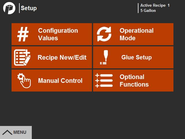
1.With the machine E-stopped, go to the Setup Menu on the HMI and select the Operational Mode (A).
2.At the Operation Mode screen, press the Manual Mode button (B)
Before proceeding with actual machine operation announce in a loud and clear voice CLEAR, listen for response and visually check that all personnel are out of harm’s way.
3.On the touch screen enclosure and at the remote mounted switch enclosure, pull out the Emergency Stop button(s). The Machine Reset button illuminates.
4.Press the Machine Reset button. The Cycle Start button begins to flash.
5.Press the Cycle Start button.
6.Go back to the Setup Menu and select Manual Control (C).
7.Touch the side arrow (D) to go to the next screen.
8.On the Manual Controls screen, use the Drives button (E) to turn the drives on. The material drive and exit conveyor motors start running. .

9.Touch the button labeled Touch To Pick Wrap (F). The body-wrap vacuum pick cylinders extends and pull one bodywrap blank from the bottom of the stack. The button changes to Touch to Kick Wrap.
10.Press Touch to Kick Wrap (G). The body-wrap travels through the material belt drive until it is centered under the mandrel blocker.
11.Press Touch to Kick End Panel (H). The end panel blank is driven against and formed around the mandrel blocker by the internal flange fold shoes.
12.When both pieces are in place the mandrel blocker drives the end panel blank into the body-wrap blank and down into the die frame assembly where it is formed into a completed container.
13.This completes one container cycle. When the box exits the machine, use the Drives button to turn the drives off. The material drive and exit conveyor motors will stop running.
14.Examine the container construction before proceeding to AUTOMATIC MODE.
Normal changeover and adjustments are listed in Case Adjustment Points and can be done by the machine operator. Machine performance adjustments should be done ONLY by knowledgeable personnel.
1.Ensure that blanks are properly loaded in the magazine. Remove badly deformed blanks or those out of tolerance with specifications.
2.Ensure reliable stripping of blanks from magazine.
3.Make certain the adhesive system is loaded and operating properly.
4.Ensure all sensors are clean, correctly adjusted and functioning properly.
1.Every hour one case should be removed from the line and inspected by observation and disassembly. This will ensure that any problem with the machine or the material is less likely to cause case failure. Cases should be inspected in the following areas:
a.End panel seated against the body-wrap. This is important to the stacking strength of the case. The end panels should be fully seated on the body-wrap.
b.Top of case tapered outward. It is normal for the top of the case to be slightly wider than the bottom, however, the amount of this taper should be no more than 1/8”.
c.Glue joints. When any case is torn apart, the corrugated liner on one side of the joint should be torn. This is called fiber tear. You also want to check the length of the glue lines. The end of each body wrap glue line should extend to within 3/8” to 1/2” of the end of the paper.
1.Check to see the end panel is seated evenly in the body wrap.
2.Check to see that completed box is all around square.
a.Measure on the diagonals (see illustration) are dimensions equal within plus or minus 1/8”?
a.Are overlaps even, did the material bend at a right angle on the score lines.
3.Tear open a glued portion of the box. Is the glue joint approximately 1/4” wide, did the corrugated material separate from itself along the glue line?
a.If these conditions are satisfied continue on to Automatic Mode.
b.If not, one or more machine components needs adjustment. Go to the Troubleshooting section of this manual or access the troubleshooting section of the touch screen control for possible cause and effects.
1.To stop automatic operations press the Cycle Stop button. The machine will complete the last container. The container remains on the mandrel blocker, the horizontal die plates in the up position.
1.Press any of the emergency stop red push buttons.
2.If emergency red push buttons are not within reach, open any of the SAFETY INTERLOCKED DOORS and the machine will instantly stop.
Note: All operating power is immediately cut and the air is “dumped” (all operating lamps go out). Suddenly stopping the machine in this manner will not damage the equipment.
Note: This machine is equipped with a pressure sensing device which serves two functions. The first is to prevent the machine from operating with inadequate air pressure. The second function is to sense any air pressure left after a system “dump.” A signal horn will sound and a RED warning panel will be displayed on the touch screen control indicating air pressure in the system DO NOT ENTER MACHINE. until air can be bled off.
Note: All emergency stops are maintained stops and must be pulled out and the Machine Reset button pressed before power to machine will resume.
3.Clear the cases from the set up section.
4.Pull out all emergency stop buttons, then restart machine operations.
Ensure all personnel are clear before restarting.
5.Press the Machine Start button.
6.Allow air pressure to build to machine.
7.Press the cycle start/stop button to begin machine sequence.
If the main electrical disconnect has been turned off, it many be necessary to clear any cases in process before restarting the machine.
To clean out product currently in the magazine in preparation for a product size change, follow the instructions below.
1.Remove the product from the magazines.
This chapter discusses the proper way to unpack and level the machine, pre-run preparation steps, how to connect the electrical and air supplies, and any final checks necessary before starting the machine.
Thoroughly inspect machine for shipping damages before and after removing from transport carrier's vehicle. Note any apparent damages and capture with video or digital photos. Indicate any areas of damage on shipping documents and with Pearson Technical at 800-732-7766.
Note: If the machine arrives with change parts, unpack the box carefully and identify all parts. Notify Pearson's Service Department at 800-732-7766 if parts are missing.
1.After inspecting the machine, use a fork lift or electric pallet jacks to slide the skidded machine to the work location.
To protect the machine feet from damage, leave the machine skidded when moving.
To prevent damage to the machine ensure the fork lift forks or pallet jack forks bear against the skid only when moving the machine. Do not use forklift on the underside of the frame.
2.Check for any loose bolts, nuts or fastenings. Tighten as necessary.
Note: It is not uncommon for bolts, nuts and fastenings to become loose during shipment due to vibration.
3.It is not uncommon for bolts, nuts and fastenings to become loose during shipment due to vibration.
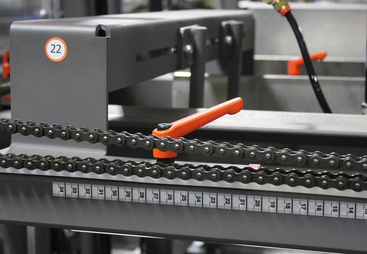
4.Check that drive chains are tight. If not, tension using a chain sag equivalent of 2% of the center distance.
5.Shipping bolts are identified by a yellow tag; (See Fig: 1 - Shipping Bolt Tag).

•4 ft. Minimum Bubble-type Level
•¾” Wrench or Socket
Note: A bubble-type level (4 ft. minimum) is useful when leveling the machine.
Prior to leveling the machine, place anti-seize on the leg leveler threads. Install the leg levelers.
Note: Optional leg extensions may be required if the machine deck exceeds standard elevation.
1.Refer to machine floor plan drawing for machine height.
2.Extend all leg levelers to desired machine height.
3.Adjust the leg levelers until the machine is level.
4.Perform a test run of the machine.
5.Make any necessary adjustments to the placement and/or leveling of the machine.
6.After the Pearson Packaging technician has reviewed the placement of the machine, bolt the machine to the floor to prevent movement.
Electrical Power
Note: A dedicated electrical circuit is recommended for this machine.
1.Refer to machine nameplate for voltage specifications.
2.Connect plant power to machine at the main electrical control panel. If in doubt, consult your electrical contractor.
Be sure all personnel are clear of the machine and guards are in place when starting. When the machine is connected to an air supply, the cylinders retract to the home position.
3.Using a volt meter, measure the applied voltages on the power feed to the machine main connections. Power should be ± 10% of nameplate voltage
4.Turn power on. Perform a motor rotation check of the motor. If the motor initially runs in the wrong direction, reverse the polarity. Recheck the motor.
The machine requires a clean, dry air supply with a constant pressure of 80 PSI.
Note: This machine is equipped with an electrical air supply and dump valve. Pressing the E-stop button exhausts compressed air in the machine circuit. Pulling out the E-stop button and pushing the Start button re-energizes the system.
Note: Size the air line to match the inlet line on the air prep unit.
1.Once air is connected, manually lock air (open) onto machine.
a.Check or perform a pneumatic integrity test of all hoses, fittings, and cylinders.
b.Correct any discrepancies found to leak or discharge air from pneumatic system.
2.The pressure is maintained at a constant level to the machine by use of a built in regulator.
a.The regulator may be set by pulling the regulator adjustment knob outward and turning the knob until the desired pressure reads on the gauge.
b.It will be necessary that the machine’s control power and main air output be on to set the air pressure. This is because the machine’s slow start feature will need to be open.
The values given in this chart should be used to select the minimum air line size (npt), and air compressor horsepower to supply a single Pearson Systems machine. The chart is based on a 100 PSI air supply with less than 2 PSI pressure loss. The distances are the pipe line length from the machine, back to the air compressor, or to a large header. The cubic feet per minute (CFM) value is the volume of free air which the machine uses. If more than one machine is supplied by the air line, all the CFM requirements of the machines must be totaled and the sum CFM used to determine the air line size. The air compressor horsepower rating is based on the volume of free air, at 100 PSI, that a 100% duty cycle compressor should be able to supply.
To determine the minimum air line size required, refer to the floor plan drawing to find the maximum CFM requirement. If more than one machine will be supplied, add the CFM requirement for each machine and find the total. Although the CFM required will vary with the production speed at which the machine will be used, we recommend installing a pipe size which will be sufficient at the maximum rated speed of the machine. This will avoid expensive rework in the future. Next, estimate the length of
pipe in feet, needed to reach the air compressor. Each elbow or tee fitting should be considered equal to 5' additional length. Fittings should therefore be kept to a minimum. Now find the row which is the CFM you need, and the column which is the pipe length, and this will show the minimum pipe size required.
Note: The pipe size given should be used for the entire run. Stepping down is not recommended.
1-1/41-1/41-1/41-1/41-1/41-1/21-1/222
1-1/41-1/21-1/21-1/22222-1/22-1/2
12-1/21-1/21-1/22222-1/22-1/22-1/2
2222-1/22-1/23333
Final Checks
Before making any adjustments to the machine: turn off main power; turn off air supply; follow lock out/tag out procedures.
1.Verify machine and case/tray set up before attempting to run case/tray.
2.Jog a product through the machine to ensure the machine is operating properly.
This Page Intentionally Left Blank
This chapter provides detailed instructions for changing from one product size to another.
Note: It is recommended that the following procedures be performed by a minimum of two personnel.
Note: When the air pressure to the machine has been shut off a mandrel locking cylinder engages and holds the mandrel in the full up position. DO NOT attempt this or the following procedures unless the mandrel is in the full up and locked position.
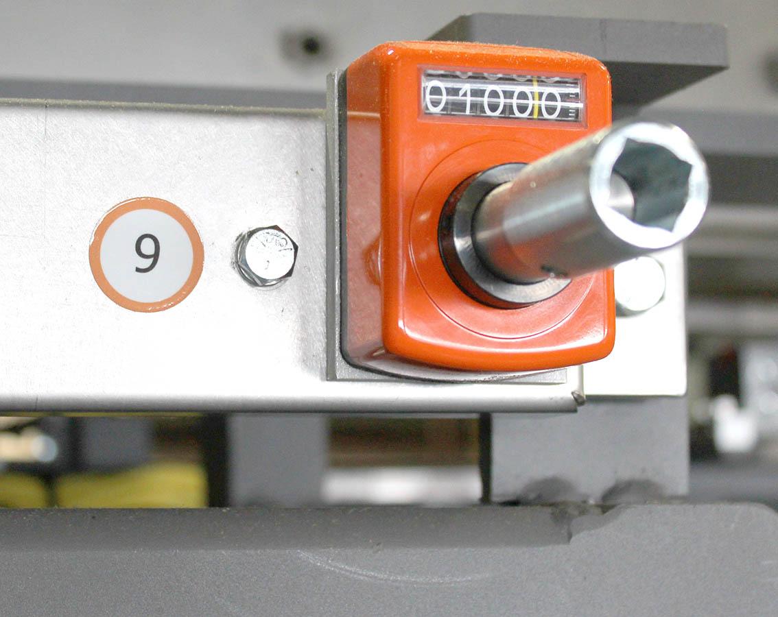
Note: With the crank handle provided, turn the end panel depth adjustment #9 lead screws counter-clockwise. This will increase the distance between the end panel magazines and provide more clearance for removing the mandrel blocker halves.
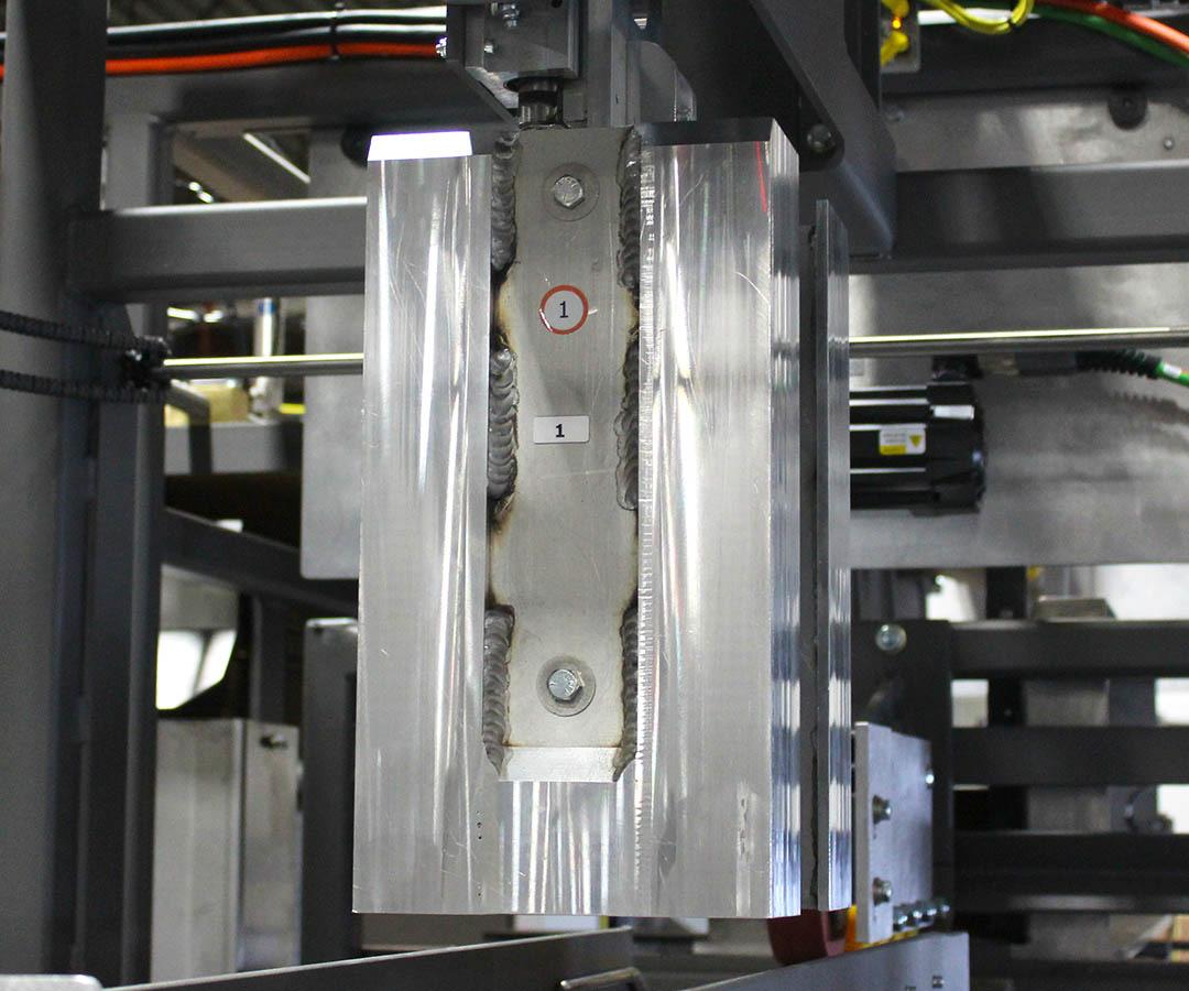
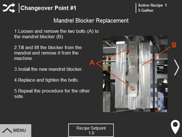
1.Loosen and remove the two bolts (A) to the mandrel blocker (B).
2.Tilt and lift the blocker from the mandrel and remove it from the machine.
3.Install the new mandrel blocker.
4.Replace and tighten the bolts
5.Repeat the procedure for the other side.
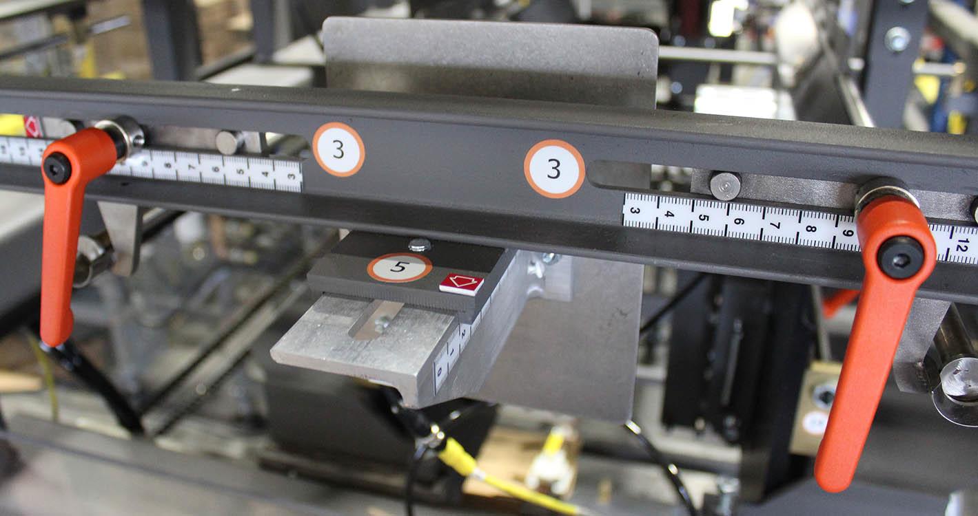
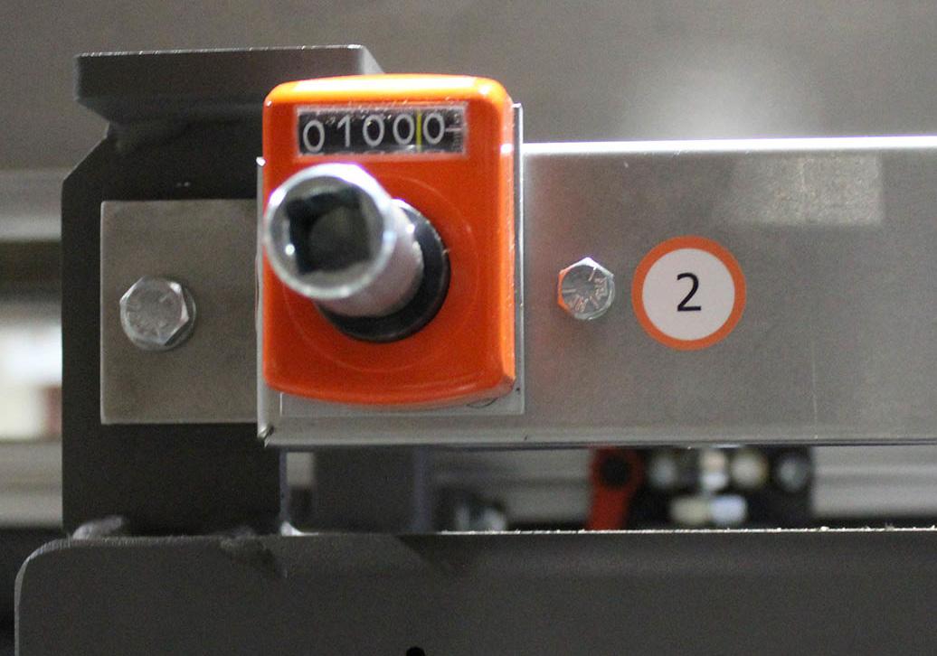
Note: Changeover points #2 and #3 are adjusted at the same time.
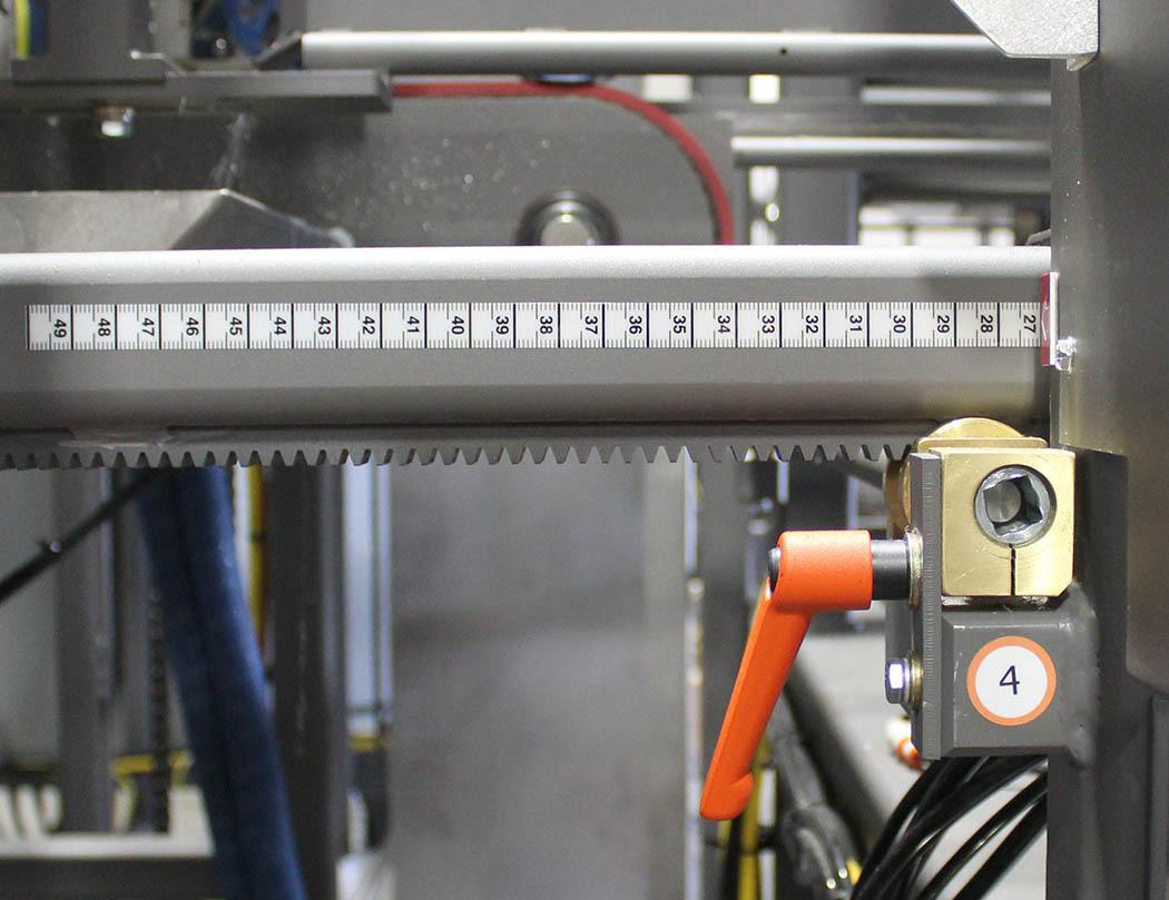
1.Loosen the two quick-release handles (A) for the body wrap guide rails (changeover point #3).
2.Use the crank handle to rotate the rod end (B) to adjust the body wrap magazine width to the appropriate setting on the digital counter (C).
3.Adjust the body wrap rails to the appropriate scale setting (D)
4.Tighten the quick-release handles.
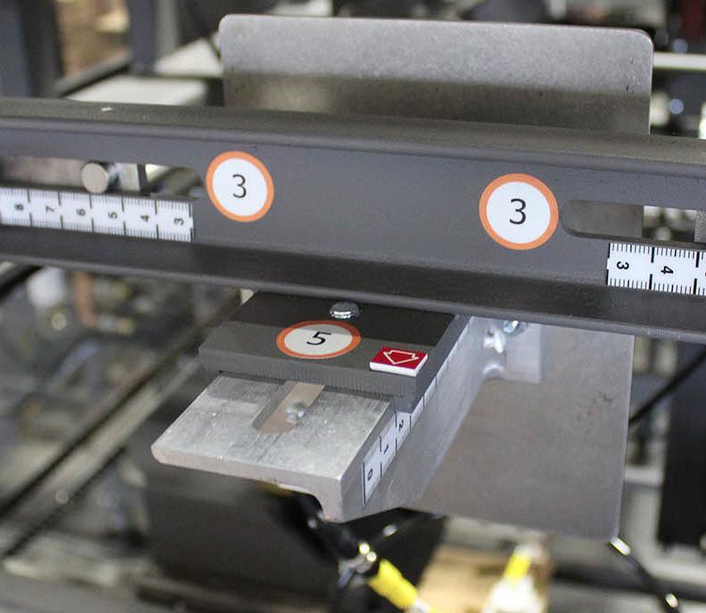
Body Wrap Magazine Dept h - Changeover Point #4
The body wrap blank needs to be centered under the mandrel blocker.
1.Loosen the quick-release handle (A)
2.Use the crank handle to rotate the rod end (B) to adjust the body wrap magazine depth to the appropriate scale setting (C).
3.Tighten the quick-release handle.
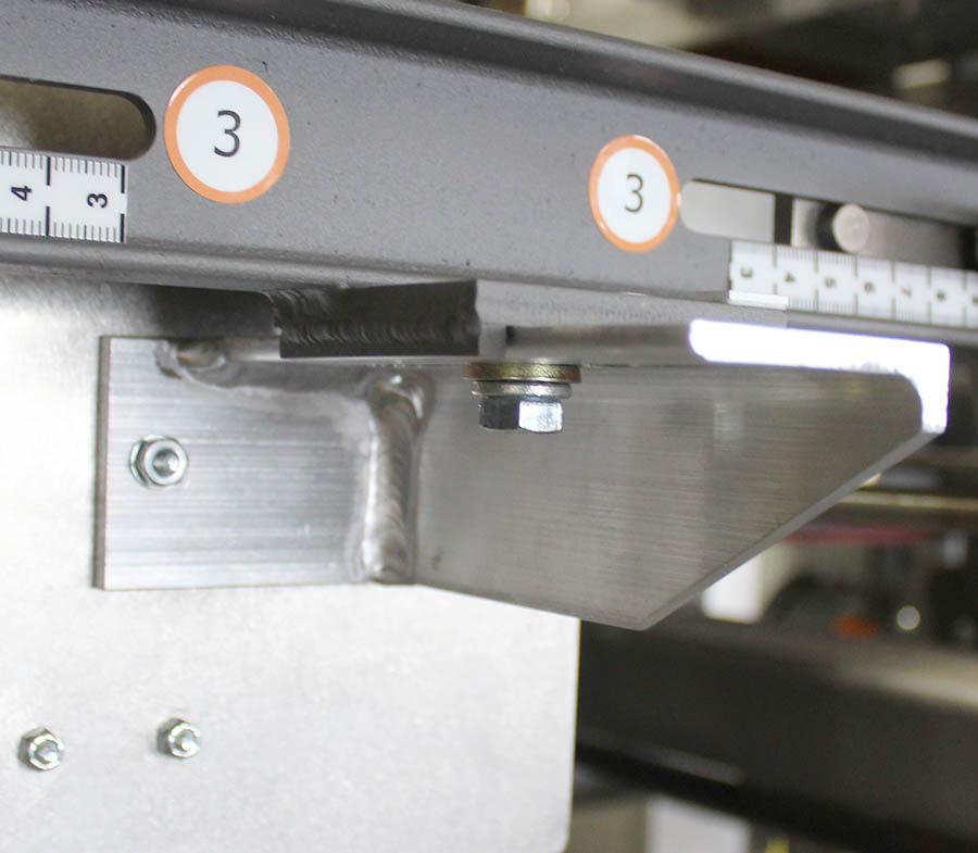
1.Loosen the bolt (A)
2.Turn the adjustment moving the body wrap magazine forward or backward until the edge of the plate is at the appropriate scale setting (B).
3.Tighten the bolt.
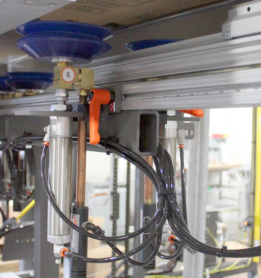
Trailing Body Wrap Vacuum Cups - Changeover Point #6
1.Loosen the quick-release handles (A) to each of the six vacuum cup assemblies (B).
2.Slide the vacuum cups assemblies to the appropriate box size. This adjustment is not scaled.
3.Tighten the quick-release handles.
1.Loosen the quick-release handle (A).
2.Slide the body wrap kicker to the appropriate scale setting (B)
3.Tighten the quick-release handle.
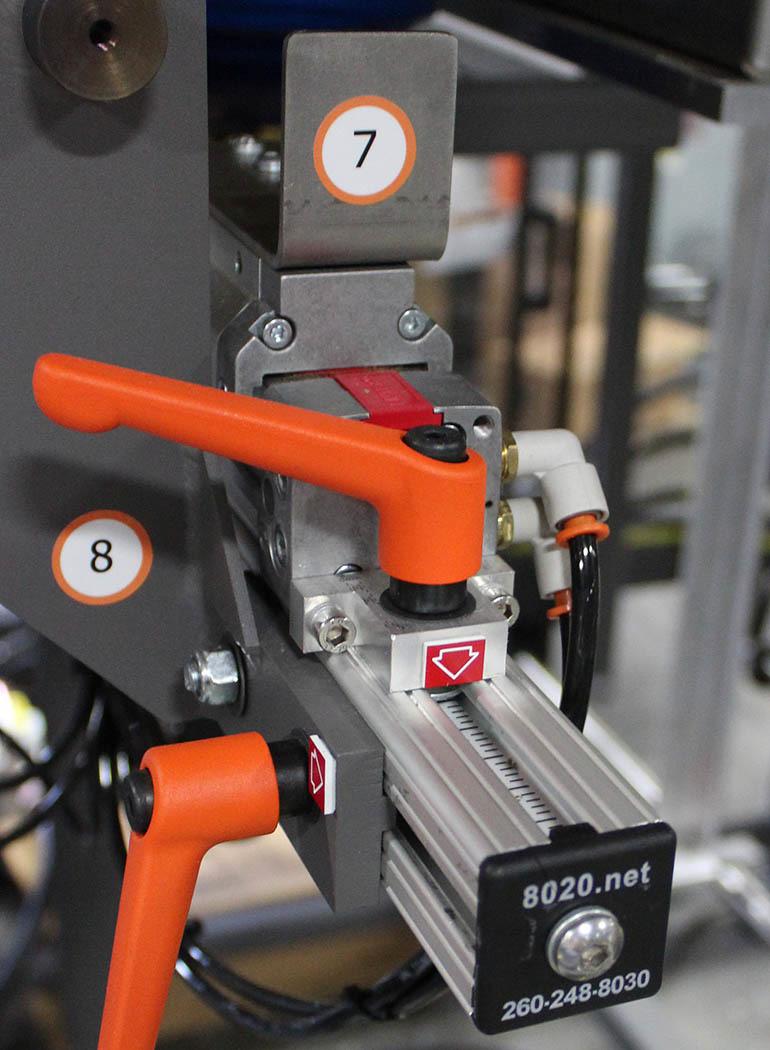
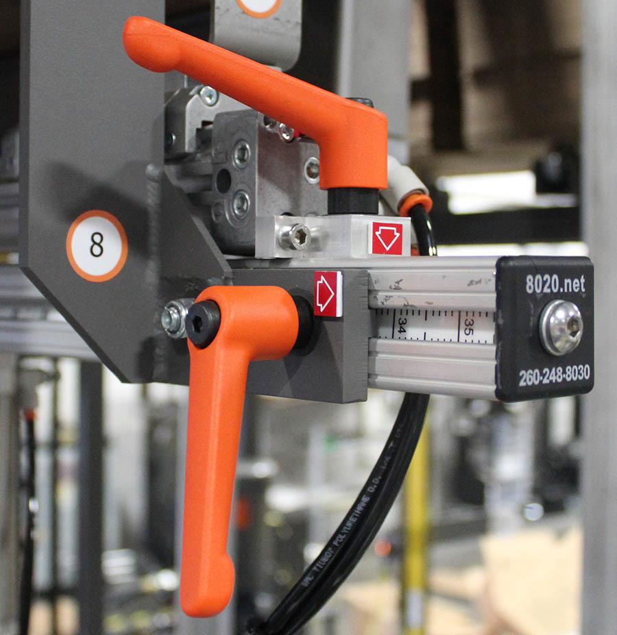
Body Wrap Kicker Backstop- Changeover Point #8
1.Loosen the quick-release handle (A).
2.Slide the body wrap kicker backstop to the appropriate scale setting (B)
3.Tighten the quick-release handle.
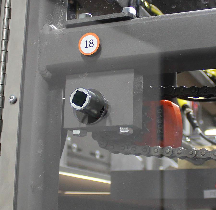
1.Use the crank handle to rotate the rod end (A) to adjust the body wrap magazine width to the appropriate setting on the digital counter (B).
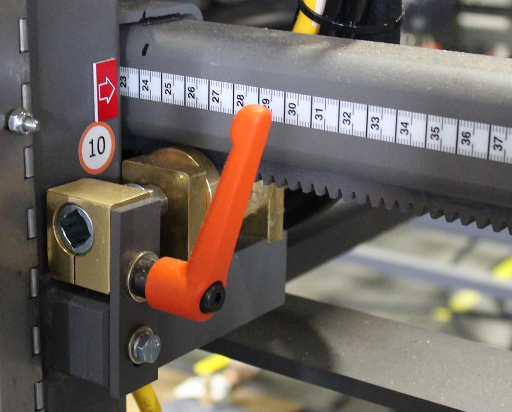
1.Loosen the quick-release handle (A).
2.Use the crank handle to rotate the rod end (B) to adjust the body wrap magazine width to the appropriate scale setting (C).
3.Tighten the quick-release handle.
Note: The distance between the end panel lower support plate and the mandrel blocker should measure 5/16”.
1.Loosen the two bolts (A).
2.Slide each assembly to the appropriate scale setting (B)
3.Tighten the bolts.
1.Use the crank handle to rotate the rod end (A) to adjust the end panel guide rails to the appropriate setting on the digital counter (B).
1.Use the crank handle to rotate the rod end (A) to adjust the end panel guide rails to the appropriate digital counter setting (B).
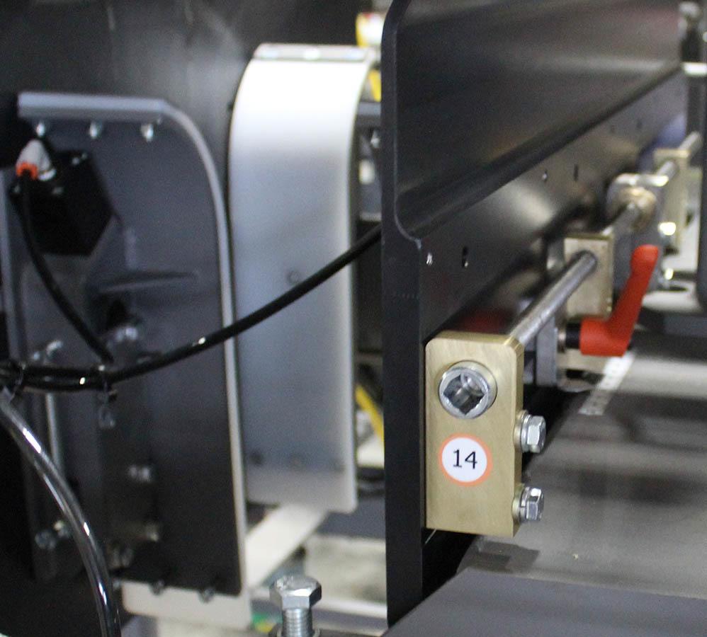
1.For each side, loosen the quick-release handle (A).
2.Use the crank handle to rotate the threaded rod end (B) to move end panel kicker backstop to the appropriate setting on the scale (C).
3.Tighten the quick-release handles.
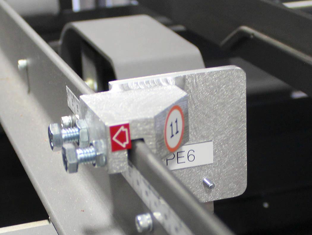
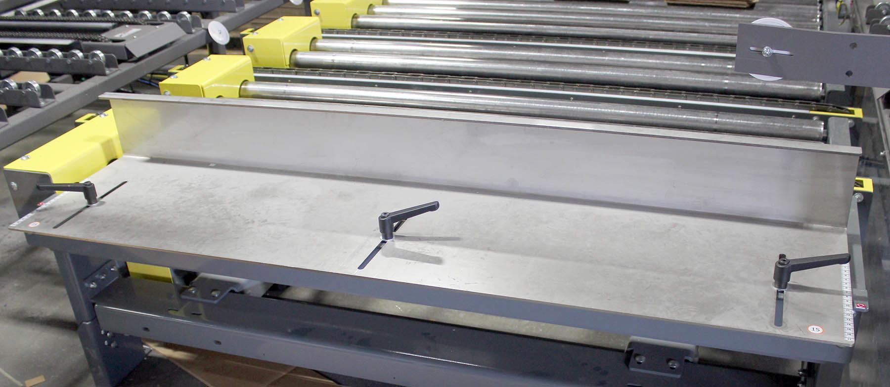
Body Wrap Conveying Bundle Mate rial Backstop - Ch angeover Point #15
1.Loosen the quick-release handles (A).
2. Move the backstop (B) to the appropriate setting on the scale (C).
3.Tighten the quick-release handles.
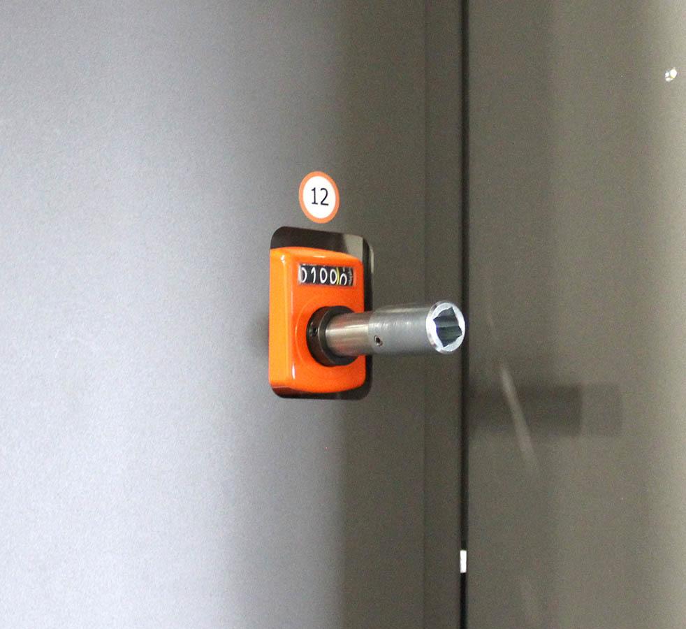
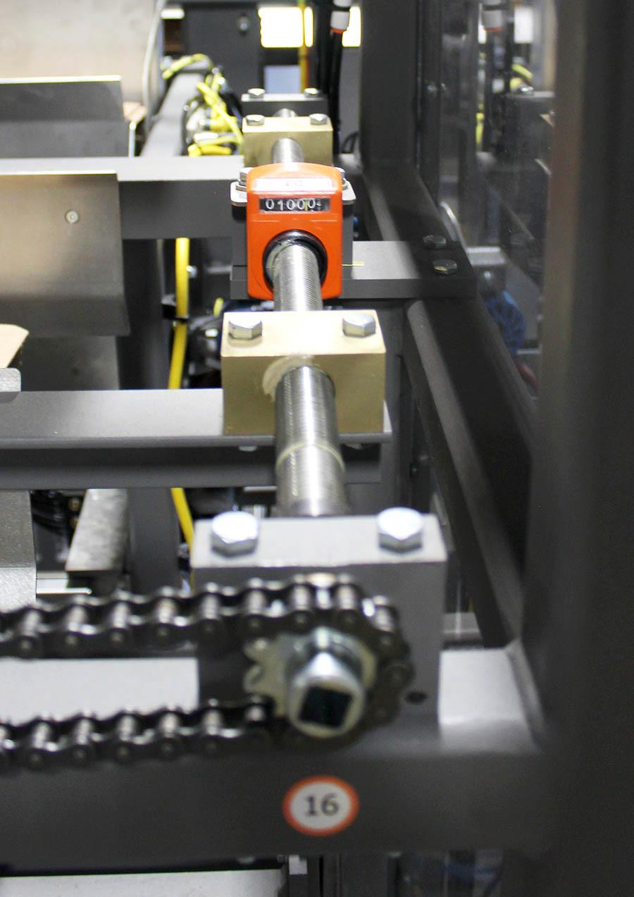
Body Wrap Bundle Feed Material Width - Changeover Point #16
1.Use the crank handle to rotate the threaded rod end (A) to adjust the width to the appropriate setting on the digital counter (B).
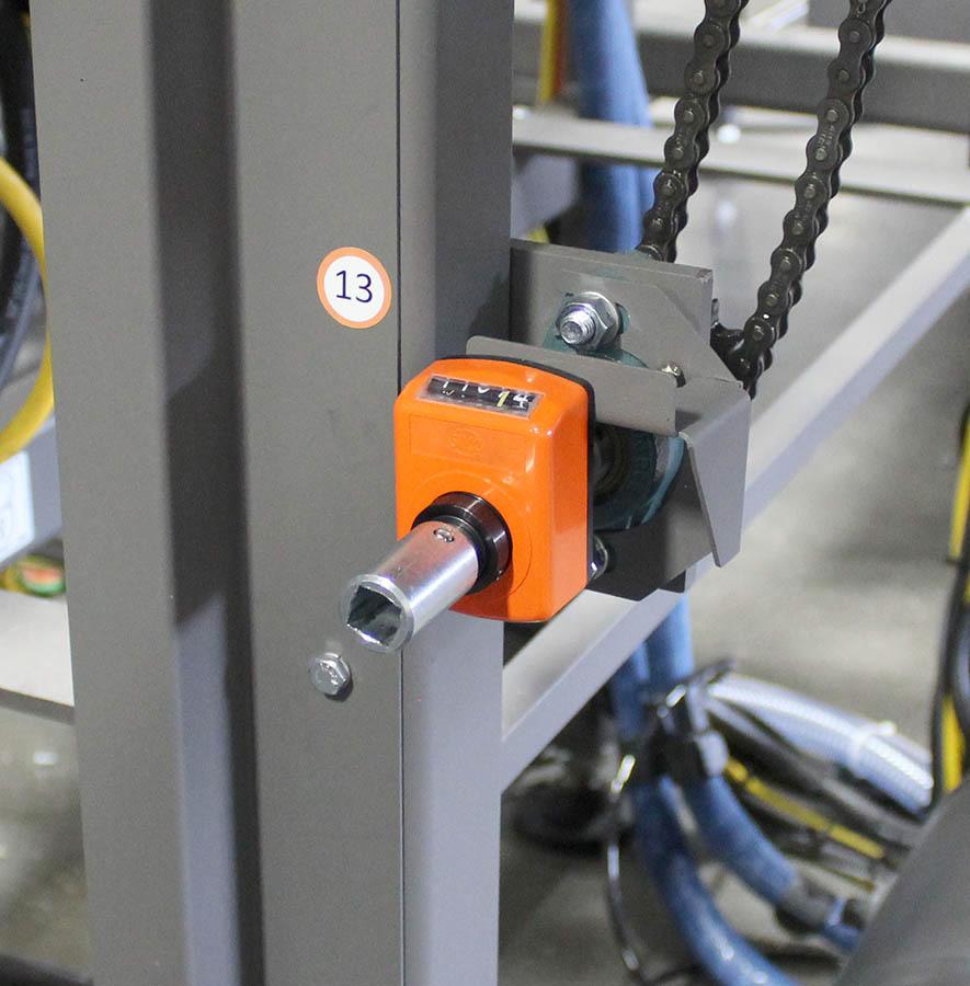
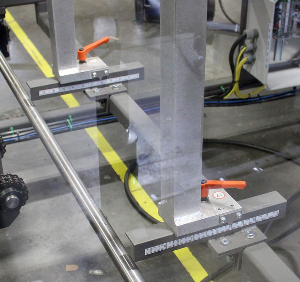
Body Wrap Conveying Bundle Mate rial Backstop - Ch angeover Point #17
1.Loosen the quick-release handles (A).
2.Move the backstop to the appropriate setting on the scale (B).
3.Tighten the quick-release handles.
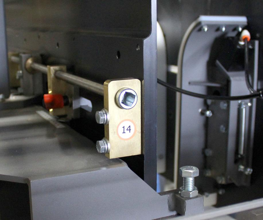
1.Use the crank handle to rotate the threaded rod end (A) to adjust the width to the appropriate setting on the digital counter (B).
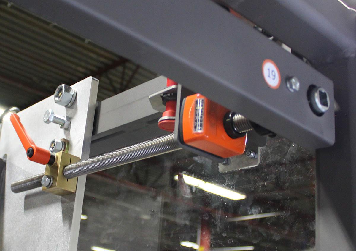
1.Loosen the quick-release handles (A).
2.Use the crank handle to rotate the rod end (B) to adjust the slitter carriage position to the appropriate setting on the digital counter (C).
3.Tighten the quick-release handles.
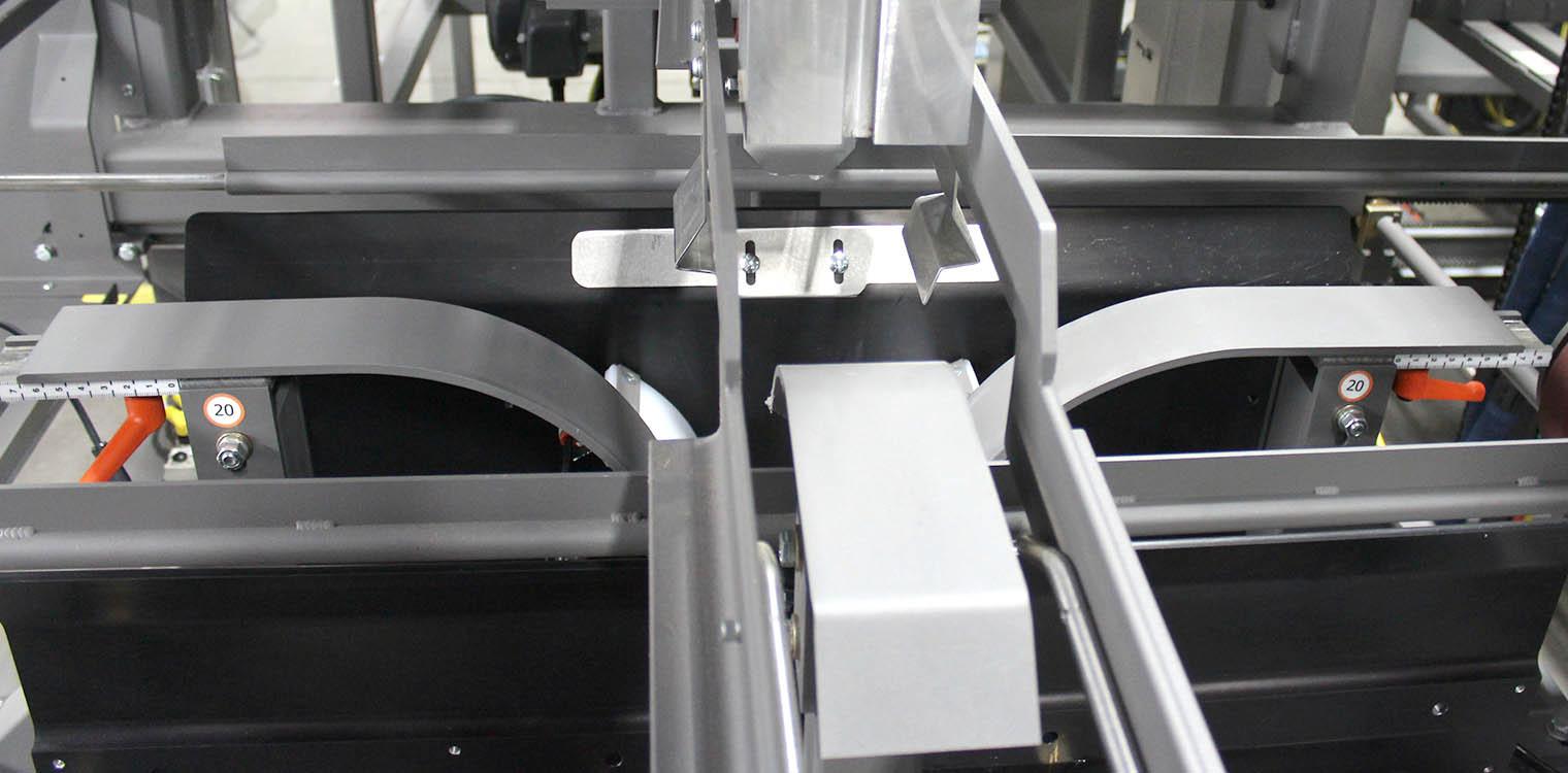
1.Loosen the quick-release handles (A).
2.Move the body wrap pre-folds to the appropriate settings on the scales (B)
3.Tighten the quick-release handles.
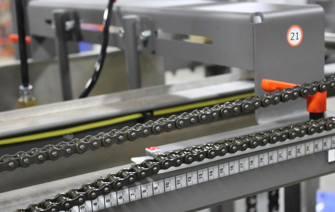
1.Loosen the two quick-release handles (A).
2.Move the trailing body wrap stack funnel to the appropriate settings on the scales (B).
3.Tighten the quick-release handles.
1.Loosen the two quick-release handles (A).
2.Move the leading body wrap stack funnel to the appropriate settings on the scales (B).
3.Tighten the quick-release handles.
This chapter provides information on the display screens located in the Allen-Bradley PanelView Plus 1000 Operator Interface; including the layout and function of each screen.
The Allen-Bradley PanelView Plus 1000 is an electronic operator interface — the operator gathers information from the LED display and presses the touch screen to perform a particular function. Some items in the PanelView can be changed directly by any operator (such as choosing case size) while other items require a password (such as servo motor parameters).
This section is intended to describe the screens and functions specific to the Pearson Packaging Systems BF30-2AS Bliss Former. For technical information about the Allen-Bradley PanelView Plus 1000, refer to the manual shipped with this machine or visit Allen-Bradley’s web site at http://www.ab.com.
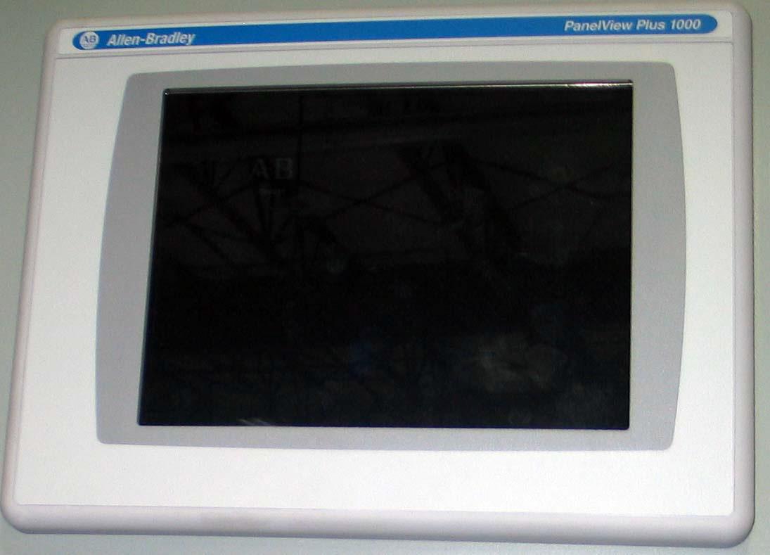
Fig: 1 - Allen-Bradley PanelView Plus 1000
Home is the first screen that appears on startup and displays during normal machine operation. It provides access to all the other screens in the HMI.
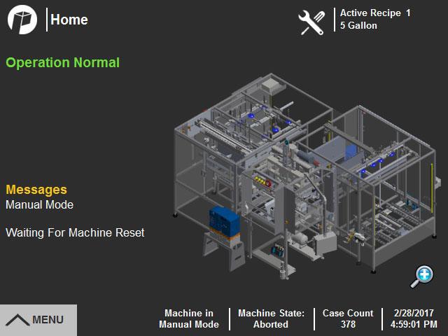
Legend Table
A Maintenance IconAppears when maintenance tasks are due. Press to go to the Maintenance screen.
B Active RecipeActive recipe display - Shows the currently active recipe.
C Alarm/Message DisplayDisplays status of machine, alarms and messages.
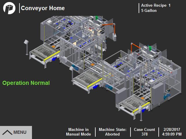
D MagnifierOpens the Conveyor Home screen, which displays a map of the system.
E Menu ButtonPress to open the Menu Bar.
F Machine Status DisplaysDisplays the current machine mode, machine state and case count.
G Pearson IconReturn to Home screen.
Menu Bar
Press the Menu button in the lower left corner of the screen to open the menu bar. The icons on the menu bar provide access to additional menu screens.

•Press Close (A) to close the menu bar.
•Press Login (B) to open the user login popup window.
IconAction DescriptionScreen Access


Returns to the Home screenChangeover Menu Setup Menu Sensor Menu Alarm Menu Maintenance Menu Help Menu
Opens Changeover MenuRecipe Select Changeover Values Map Guide
Opens Setup MenuConfiguration Values Recipe New/Edit Manual Control
Operational Mode Glue Pattern Values Optional Functions
Opens I/O MenuSensor Map Output Test Sensor Descriptions
Opens Alarm MenuAlarm History Alarm Status Alarm Descriptions Message History
Opens Maintenance MenuMaintenance Setup Required Maintenance Maintenance History Clean Lubricate Inspect
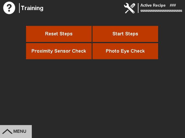
Opens Help MenuUser Manual Parts & Service Training
Wire Schematic Pneumatic Schematic
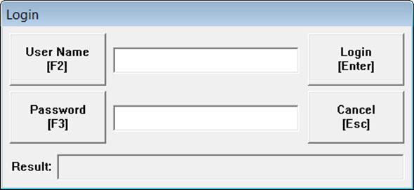
A login popup is provided for screens that require a maintenance login to make changes to machine values. The operator login is the default.
To log in:
1.Go to the Login window in one of the following ways.
a.Open the menu bar and press the Login button (A), then press Login (B) when the login popup appears.
b.Press a button for a function that requires login (C). These buttons are displayed, but appear shaded.
2.A window appears for entering username and password.
a.Press the User Name button (D) and enter the login name on the keypad.
b.Press the Password button (E) and enter the password for the login name on the keypad.
c.Press Login (F).
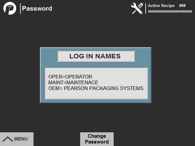
To change a password:
1.Press the Password button (G) in the Login Popup to view user names or change the password for Operator or Maintenance.
2.Log in at the appropriate level.
a.To change the Operator password, log in as an Operator.
b.To change the Maintenance password, log in as Maintenance.
3.Press the Change Password button (H).
4.Change the password and save.
Note: If the password is lost or forgotten, call the Pearson Packaging Service Department at 800-732-7766 for assistance.
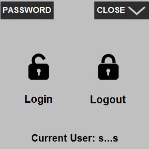
To log out:
1.When finished, press Logout (I) to go back to the default setting.
2.If the screens are not accessed within 12 minutes, the HMI automatically logs out.
3.To minimize the popup, press Close (J).
When an alarm or message is displayed on the Home screen, an indicator (A) appears at the affected area on the machine map.
•Red indicators are displayed at alarm locations.
•Yellow indicators are displayed at message locations.
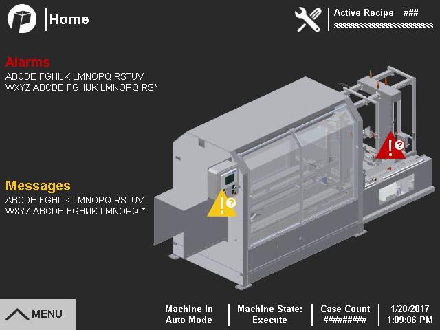
Press the indicator to go to a screen that contains details about the alarm or message, and instructions on how to fix the condition and resume operation.
Press the Changeover icon (A) on the menu bar to open the Changeover Menu Screen. Press the buttons (B) to access screens to assist with case size changeover.
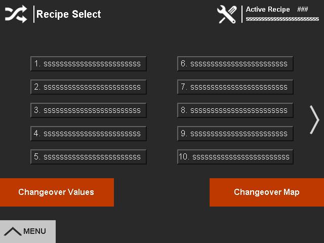
The Recipe Select screen lists the preprogrammed case size recipes.

Press the Changeover icon (C) on any of the screens to return to the Changeover Menu.
To change the case size, press E-Stop, then touch the recipe (D) for the next order to be run. A Recipe Changed message appears (E).
If there is more than one screen of recipes, press the side arrow (F) to scroll to the next page.
Changeover Values and Map can be accessed directly by pressing the buttons on the Recipe Select screen (G).

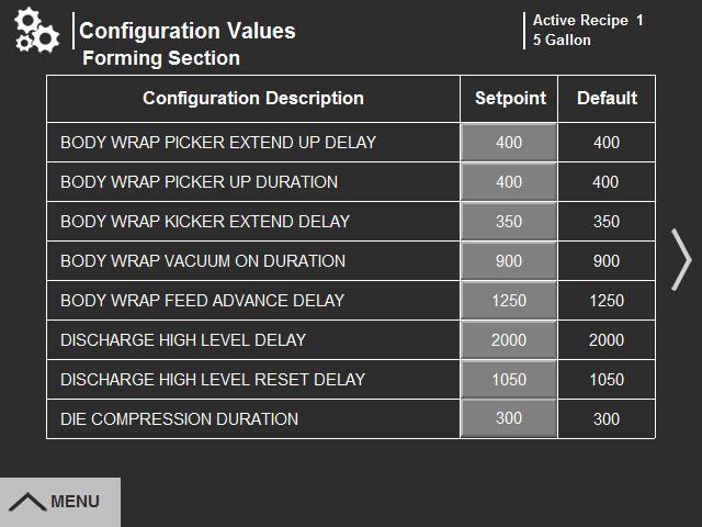
The Changeover Values screen lists the changeover setpoints for the selected recipe.
•Recipe Setpoint (A) is current setting value for the changeover point.
•The default is the value that was set at the factory.
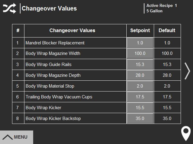
To edit recipe setpoints, log in as maintenance, then press the button for the setpoint to be edited. Follow the screen directions for changing the value.
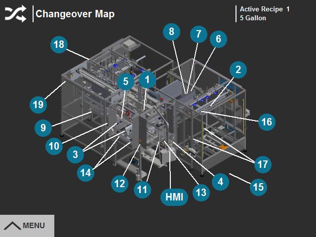
The Changeover Map screen shows a visual display of the machine showing the location of the changeover points.
Each adjustment is labeled with the adjustment number (B). Press the number to go to the guide screen for the specific changeover point.
Press the HMI button (C) to go to the Recipe Select screen.
The Guide screens contain instructions and pictures for all changeover points.
Press the arrows on the right and left sides (D) to advance to the next adjustment point screen.
Note: Depending on the number of adjustment points, there may be more than one Changeover Values screen.

Press in the lower right corner of the screen (E) to return to the Changeover Map screen.
1.Press the E-Stop.
2.From the Changeover Menu, go to the Recipe Select Screen (A).
3.Press the appropriate recipe to select the case size (B).
4.Press the Changeover Values button (C).
5.Check that the selected case size is displayed as the current case size.
6.Begin adjusting the machine starting with the first changeover point using the instructions from one of the following sources:
a.The HMI Changeover Guide screens, accessed from the Changeover Menu (D). Use the arrows (E) to move through the changeover guide.

b.The Changeover flipchart provided with the machine.
c.The Changeover chapter of this manual.
Press the Setup Menu icon (A) on the menu bar to open the Setup Menu Screen.
Press the menu buttons (B) to access screens to change operational modes, create and edit recipes, and view and edit configuration values. Machine specific screens may also be included.
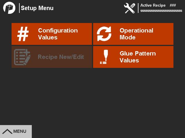
Configuration values are variables for each case. These include timer and counter settings specific to the case size and dimensions.
Press the Setup Menu icon (C) on any of the setup screens to return to the Setup Menu.
Maintenance login is required to edit configuration value setpoints (D).
Recipe New/Edit
The Recipe New/Edit screen is used to set up or copy recipes for a new case size. Maintenance login is required.
1.To add or change a recipe name, touch to select a recipe, then touch the edit button (A).
2.Add or change the recipe name and press Enter.
3.Press Yes in the popup (B) to confirm the change.
4.Enter or copy changeover values for the recipe.
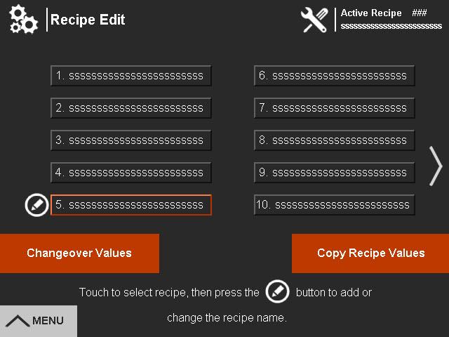

a.To enter values, press Enter Changeover Values (C) and edit the value for each changeover point.
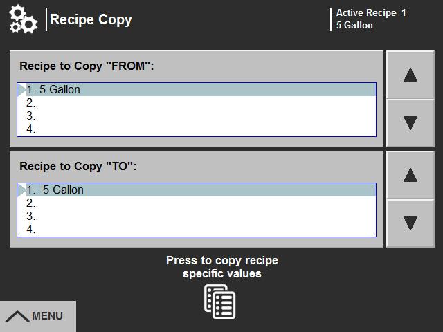
b.To copy changeover values from an existing recipe, press Copy Recipe Values (D).
•Use the arrows for the upper box (E) to scroll to and select the name of the recipe to copy from.
•Use the arrows for the lower box (F) to scroll to and select the name of the recipe to copy to.
•Press the copy button (G).
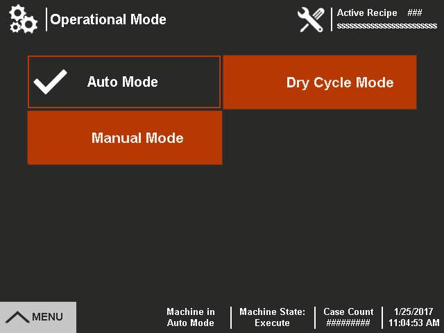
The Operation Mode screen allows the operator to place the machine in different operating modes. The current mode (A) is checked and also displayed at the bottom of the screen.
Control power must be off to change machine modes. The mode selection buttons do not appear until the E-Stop is pressed.
Manual ModeThis mode allows the operator to manually operate individual machine components. The Manual Control screen button (if applicable) only displays on the Setup Menu when the machine is in Manual mode.
Automatic ModeThis mode is used for routine production.
Dry Cycle ModeThis mode disables certain sensors, the vacuum and glue as needed to allow the machine to cycle automatically without product.
Maintenance Mode (if applicable) This mode is used for diagnosing problems with the machine. It jogs all axes at the same time with the capability to run cases without gluing them. The Maintenance Control screen button only displays on the Setup Menu when the machine is in Maintenance mode.
1.Select the Operation Mode screen from the Setup Menu.
2.E-Stop the machine. The mode selection buttons appear when control power is off.
3.Press the appropriate operation mode button.
4.Pull the E-Stop. The blue Machine Reset button lights.
5.Press the Machine Reset button.
6.Press the Cycle Start button to start the machine running in the selected mode.
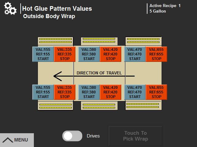
The Glue Setup screen displays recipe and factory setpoints for different glue patterns.
Maintenance login is required to edit glue pattern recipe setpoints (A).
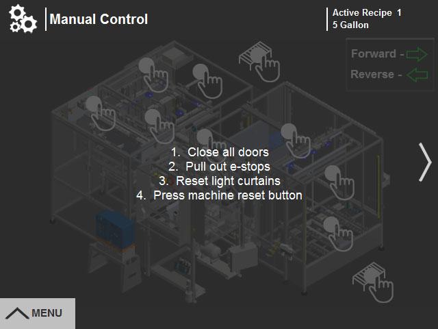
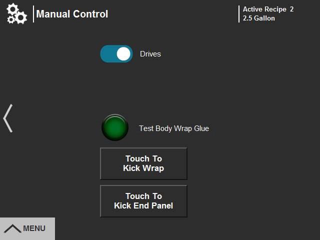
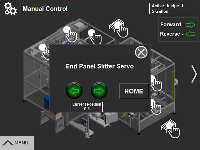
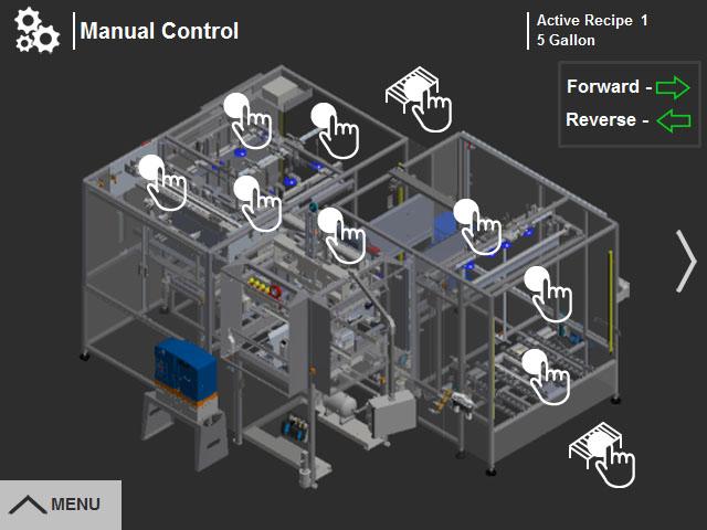
The Manual Control screen provides access to manual functions for areas of the machine. Control power must be on for the screen to be active. Follow instructions on the screen (A) to activate manual controls.
Press the side arrow (B) to go to the next Manual Control screen.
•The Drives switch (C) manually turns the material drive and exit conveyor motors.
•Press the Test Body Wrap Glue button (D) to test the operation of the body wrap glue.
•The Pick and Kick buttons (E) are used to manually build a test box. See “Making A Box in Manual Mode” on page 5-11 for the procedure.
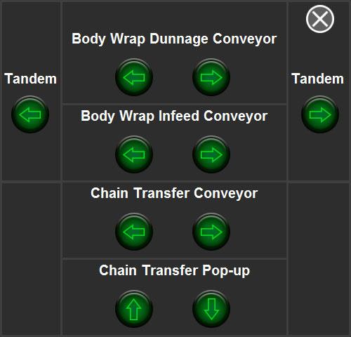
Each of the hand icons (F) on the machine map displays a manual controls pop-up window (G) for that area of the screen. Press the X (H) to close the pop-up.
Home buttons (I) are provided to send servos to the home position.
Arrow buttons (J) run conveyors forward or reverse and move components up and down. Tandem buttons (K) run two conveyors simultaneously.
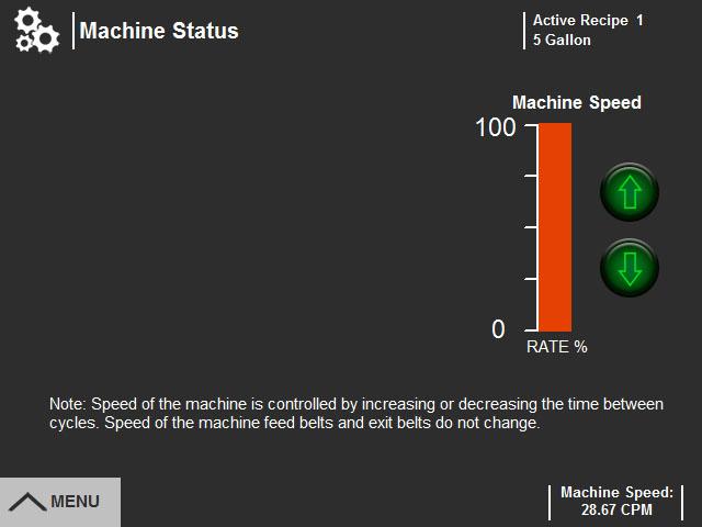
The Optional Functions button on the setup menu opens the Machine Status screen.
Use the arrows (L) to adjust the machine speed.
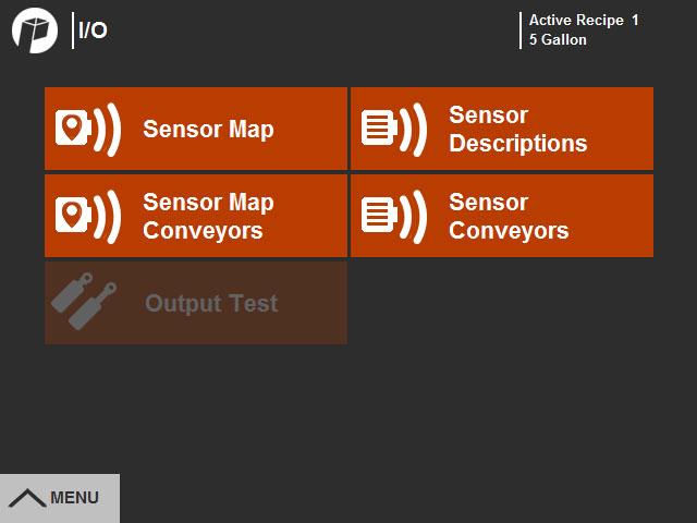
Press the I/O Menu icon (A) on the menu bar to open the I/O Menu screen. Press the buttons (B) to access the Sensor Map and Description screens, and the Output Test screen.
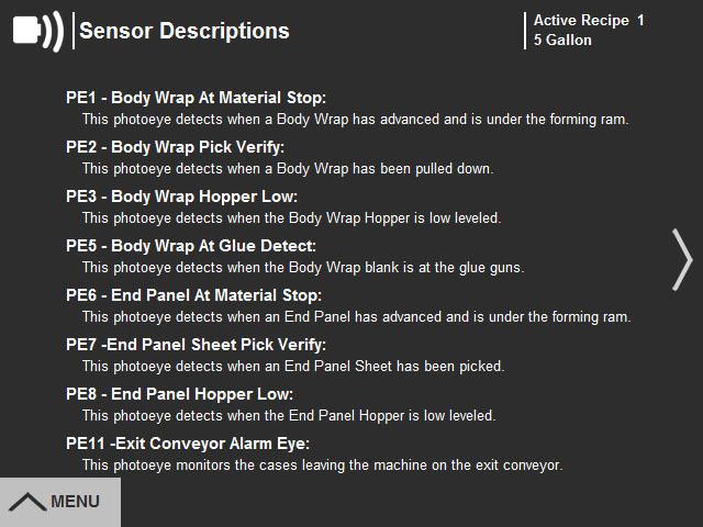
The sensor description screens explain the function of each sensor.
Press the side arrow (C) to go to additional sensor description screens.
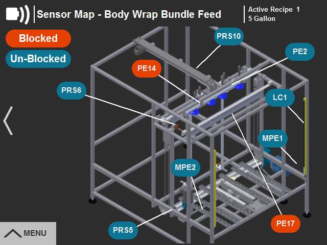
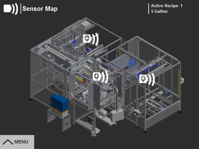
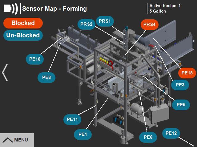
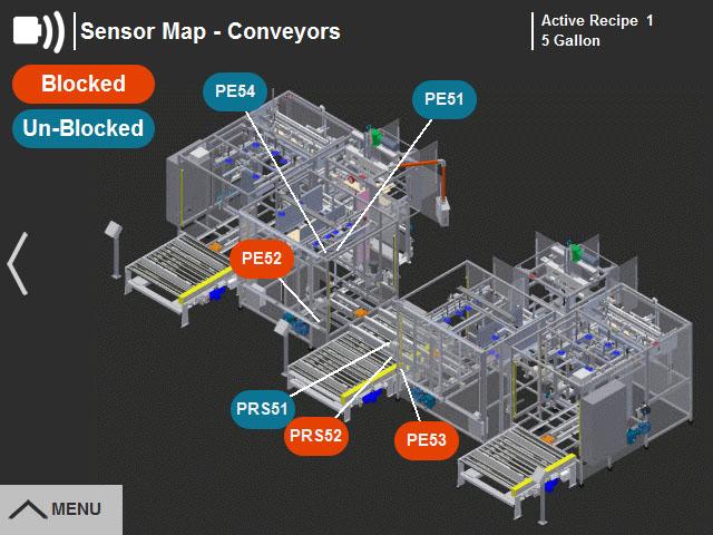
The Sensor Maps show all the sensors on the machine. As the machine operates the sensors on the map change color as they activate or deactivate.
Press one of the sensor icons (A) on the initial sensor map screen to display sensor maps for the body wrap bundle feed, forming section or conveyors.
Press the I/O Menu icon (B) on any of the sensor screens to return to the I/O Menu.
The Output Test screen allows the operator to manually energize the solenoids controlling the pneumatic mechanisms of the machine.
Maintenance login is required. Follow the instructions (A) to enable the output test buttons.
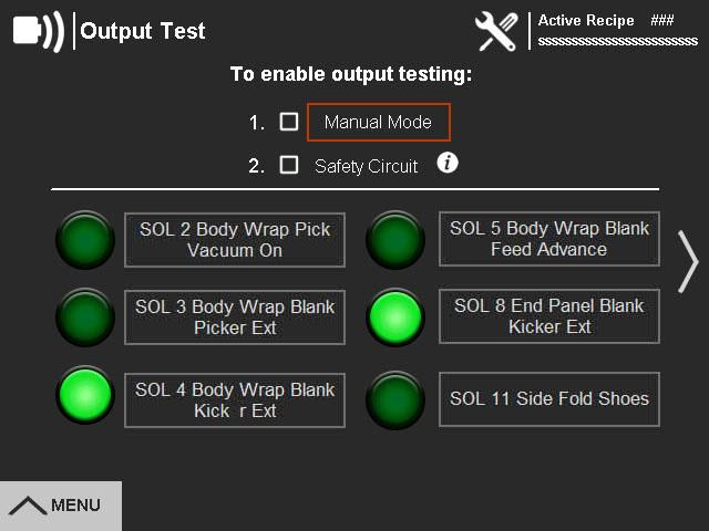
The information button (B) opens a popup window additional instructions.
To close the popup window, press the X in the upper right corner (C).
When the output test buttons have been enabled, press a button to activate the indicated mechanism (D).
Press the Alarm Menu icon (A) on the menu bar to open the Alarm Menu screen. Press the buttons (B) to access alarm and message screens.
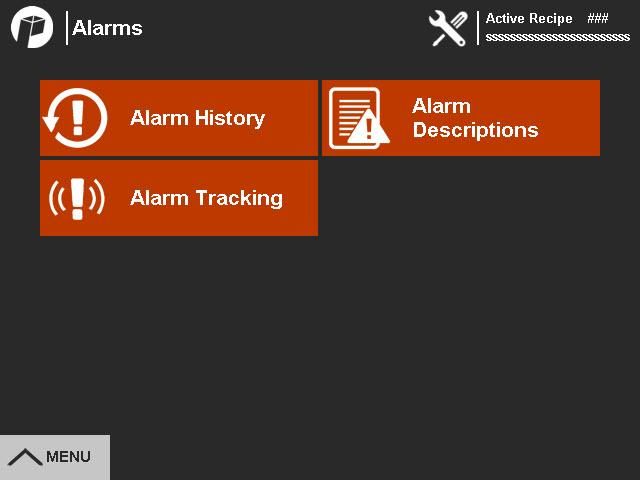
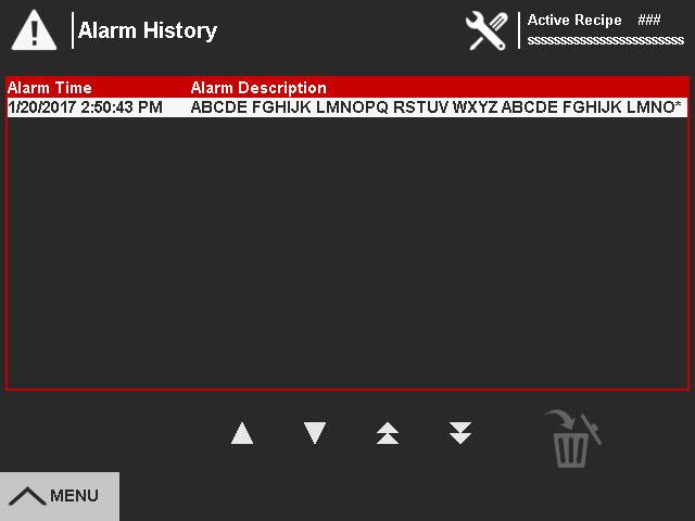
The Alarm History lists the alarms that have occurred on the machine.
Press the Alarm icon (C) on any of the screens to return to the Alarm Menu.
Use the directional arrows (D) to scroll up or down the list.
Press the Trash Can icon (E) to clear the Alarm History. Maintenance login is required.
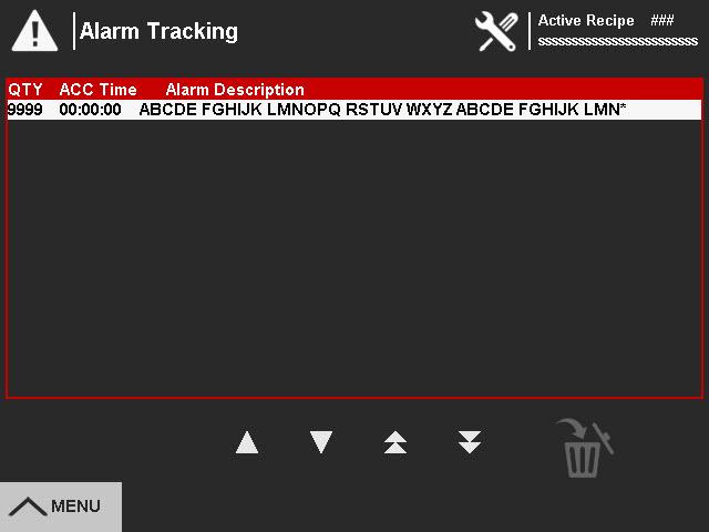
The Alarm Status screen is a data collection screen that accumulates the frequency and cumulative time the current alarm was active.
Use the directional arrows (A) to scroll up or down the list.
Press the Trash Can icon (B) to clear the Alarm Status.
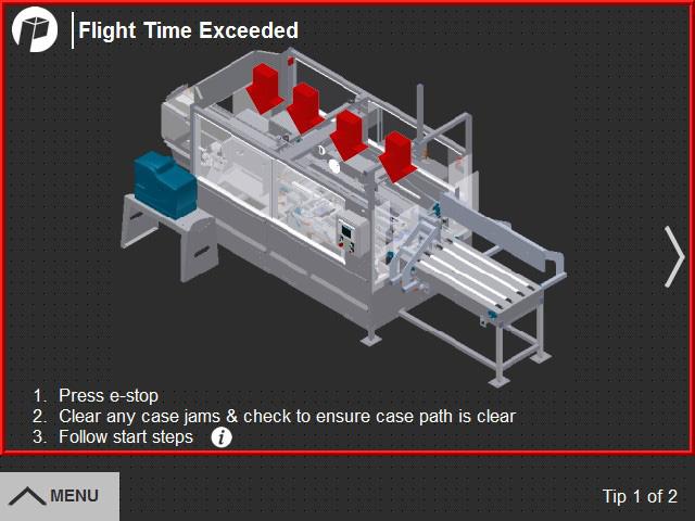
The Alarm Descriptions screen provides a menu of fault information screens. Press the alarm button (C) to open a fault screen with troubleshooting steps for the selected alarm.
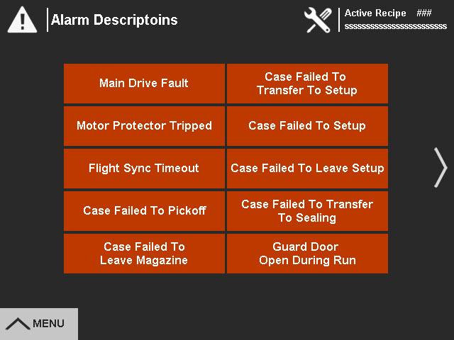
The information screen describes the steps for correcting the fault and resuming operation. Press the icon (D) to return to the Alarm Descriptions screen.
Press the Maintenance Menu icon (A) on the menu bar to open the Maintenance Menu screen. Press the buttons (B) to access maintenance screens.
Press the trash can (C) to clear the case counter.
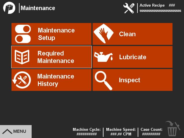
The Maintenance Setup menu displays a list of scheduled maintenance tasks for the machine (E). A maintenance login is required to make any changes.
Press the Maintenance icon (D) on any of the screens to return to the Maintenance Menu.
When scheduled maintenance tasks are due, the Maintenance icon (F) appears at the top of the screen. The tasks are displayed on the Required Maintenance screen.
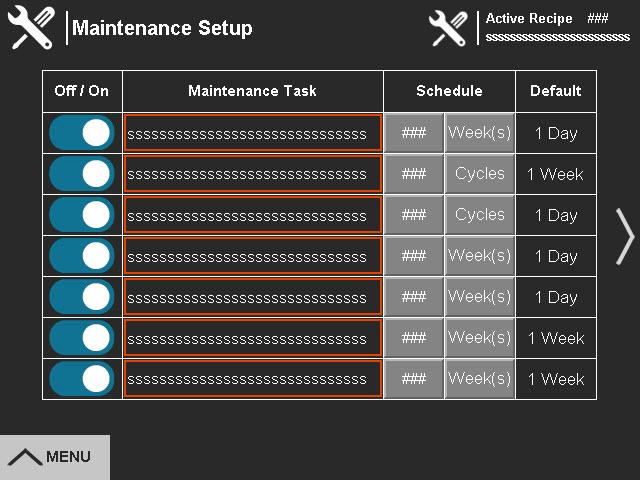
In addition to the factory set maintenance tasks, there are five additional spaces for customer configured maintenance tasks. Maintenance login is required to add tasks.
Add a task as follows:
1.Press an blank maintenance task name (A) and enter a task name on the keypad that appears.
2.Enter a schedule for the task.
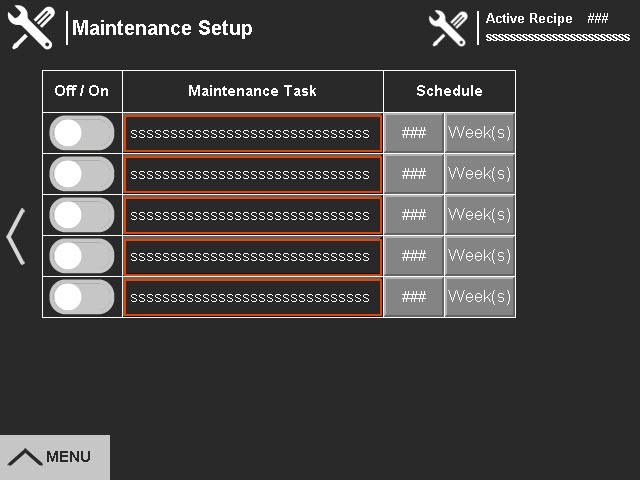
a.Press the first schedule button (B) to enter the number.
b.Press the second schedule button (C) to select the unit of time.
3.When the task has been created, press the on/off toggle (D) to turn the task On.
The Required Maintenance screen displays a list of maintenance tasks that are due to be completed. Use the direction arrows to scroll through the list (E).
Press the menu buttons (F) to go to the Clean, Lubricate or Inspect menus to access information screens about performing the required maintenance tasks.
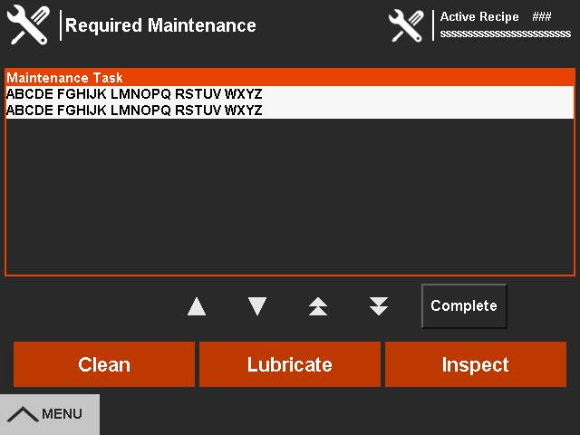
When a maintenance tasks has been completed, scroll to select it and press the Complete button (G) to clear it from the list.
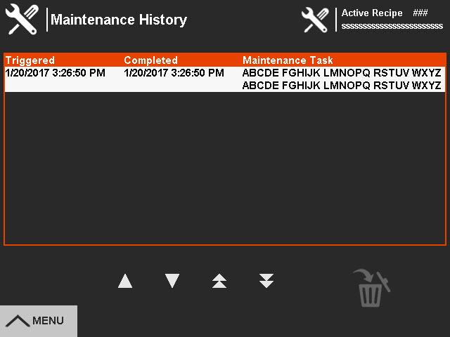
The Maintenance History screen displays a list of completed maintenance tasks. Use the directional arrows (A) to scroll up or down the list.
Press the trash can (B) to clear the maintenance history. Maintenance login is required.
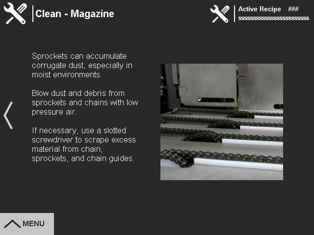
The Clean menu button on the Maintenance Menu opens a menu of points that require cleaning for the specific machine.
Lubricate and Inspect menu buttons open similar menus for lubrication and inspection points.
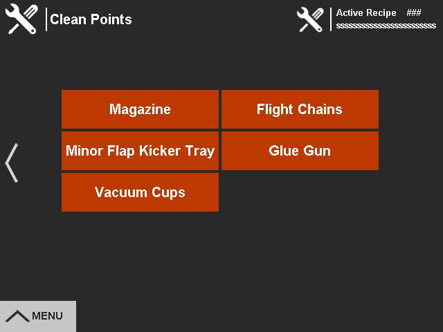
Press a menu button (C) to open an information screen that provides instructions for cleaning, lubricating or inspecting that point.
Press the side arrow (D) to return to the menu.
Help Menu
Press the Help Menu icon (A) on the menu bar to open the Help Menu screen. Press the buttons (B) to access machine documentation and contact information.
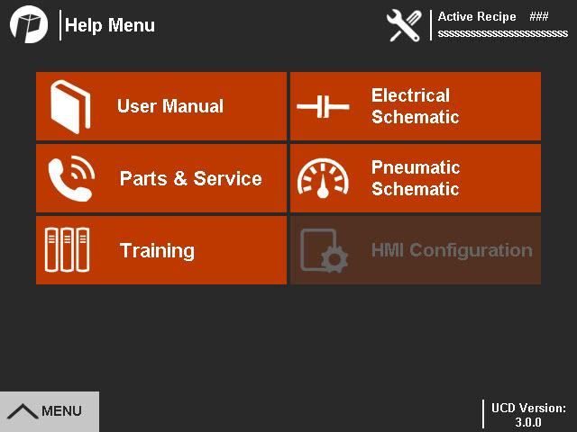
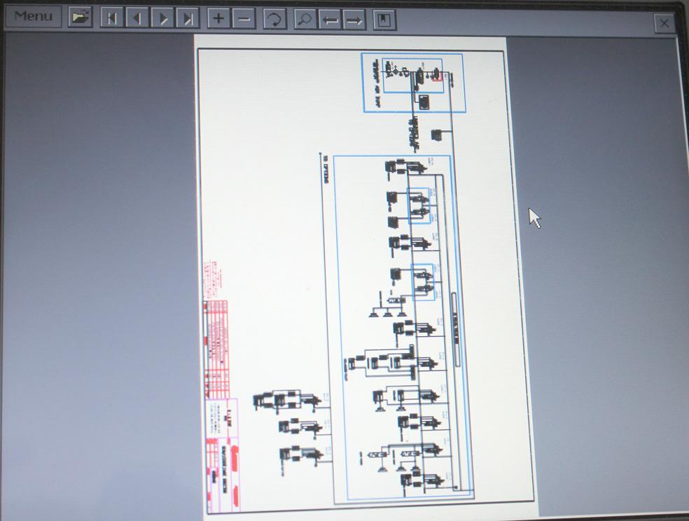
Press User Manual, Wire Schematic or Pneumatic Schematic to open the document in a PDF viewer.
To exit the viewer, press the X in the upper right corner (C)
If the schematic is oriented incorrectly, press the Rotate button (D) to turn it clockwise 90 degrees until it is correct.
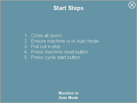
Press the Training button on the Help Menu to open the Training Menu.
Press the buttons (E) to access instructions for machine operations.
To close the popup window, press the X in the upper right corner (F)
This chapter provides troubleshooting scenarios and possible solutions.
Note: If the information provided in this chapter does not resolve or provide a resolution for the machine issue being experienced, please contact our Service Department at 800-732-7766. When prompted, enter 2 for the Service Department. Select the appropriate number for the service branch you would like to contact when prompted.
•Service Parts: Enter 1.
•Service Technical Support: Enter 2.
•Service Scheduling Coordinator: Enter 3.
•Service Engineering Quote Team: Enter 4.
Always disconnect electrical power and air before removing any guards or shrouds when performing troubleshooting. Removable guards are marked with appropriate safety labels. Never operate the machine when guards are missing. FOLLOW YOUR COMPANY'S LOCK OUT/TAG OUT PROCEDURES.
ProblemPossible Solution
Machine does not start.
Ensure all guard doors are closed securely.
Check guard door interlocks to ensure circuits are being completed.
Check that all E-stop buttons are reset (pulled out).
Check power circuit (supply voltage, fuses and disconnects).
Verify the motor is properly connected and no mechanical problems exist.
ProblemPossible Solution
Motor is not rotating.
Motor is not accelerating properly.
Verify the motor is properly connected and no mechanical problems exist.
Check motor overloads and fuses.
Check the frequency source.
Check the control input signals.
Check the parameter settings.
Verify the motor is properly connected and no mechanical problems exist.
Check motor overloads and fuses.
Check the frequency source.
Check the control input signals
Check the parameter settings.
Do not open the variable frequency drive units until three minutes have elapsed after switching off the power supply.
Machine fails to run.
HMI (if equipped) is off-line.
Drive system fails to run.
Turn on the main disconnect and follow startup procedures.
Check for motor overloads.
Check fuses.
Clear jams and check the functioning of the jam detectors.
Check both ends of HMI cable to verify it is not loose or unplugged.
Check HMI set up for communication baud rate. Rate should equal 9600. Consult Pearson Service department for instructions on accessing HMI Set up.
Check the drive chain
Check the motor/brake
Check the gearbox
Flight chain (if equipped) fails to run. Remove any debris jammed in the machine.
Turn on the main disconnnect and use the start-up procedure.
Ensure the flight lugs are not catching or rubbing on the sprockets.
Check the spur gears inside the overhead to be sure they are engaged.
Tension the chains, adjust pulley, check the motor, gear reducer pillow blocks, and chains for defective components. Lubricate, repair or replace defective components.
Troubleshoot the electrical system.
There is a main drive over-current. Verify the chains are not binding.
Verify the current of the Variable Frequency Drive (VFD) has not exceeded the preset allowed.
Verify overloads are set per electrical print.
Machine jams. Check the alarm banner on the HMI (if equipped).
Check the set-up.
Troubleshooting hot melt adhesive gun. Consult your Nordson Glue Manual.
Troubleshooting tape head. Consult your Dekka Tape Head Manual.
This chapter provides information on daily and weekly machine preventive maintenance.

Before performing any machine adjustment or maintenance, close the Pneumatic Energy Isolating Valve and the Electrical Disconnect. Follow your company’s lock out tag out procedures.
1. Next to regular lubrication, the most important item of preventive maintenance is REGULAR CLEANING!
a.Keep your machine clean for longer, safer trouble-free operation.
b.Keep dust out of the motors, chains, springs, and other key working parts.
c.Routinely use compressed air to blow dust from the machine.
Ensure personnel are clear of machine and wear proper eye protection! Never turn blower hose directly upon skin.
2.Regularly wipe off dirt, dust, and excess grease and oil.
Never hose-down or steam-clean this machine, as water and/or steam will harm electrical parts.
3.Keep the operator’s area free of debris or discarded cases and partitions.
1.To prevent early oxidation, use a soft, clean cloth to apply light-weight, foodgrade oil to the unpainted machine and metallic machine components on a monthly or as needed basis, dependent upon machine use and humidity level of the environment.
The monthly lubrication is variable depending on the machine operation time and environment. Machines operating on a 24 hour schedule or in an environment containing higher concentrations of dust, dirt or debris may need to be wiped down and lubricated more frequently.
Failure to regularly apply light-weight, food grade oil to the machine and metal machine components may result in premature oxidation.
1.Painted surfaces, which are displaying surface rust, should be lightly sanded and cleaned.
2.Wipe down the machine with a neutralizer, such as vinegar.
3.Spray a light coat of Steel-It, or equivalent corrosion-resistant paint, to touch up scratched areas to prevent further oxidation.
Remove paper dust from the machine at the end of every shift or as needed. Take special note around all sensors, (clean the lenses of all photo eyes with a soft dry cotton cloth), the material hoppers, around the drives, in the die compression cavity and around the working area of the machine.
The areas around the glue guns need to be cleaned at the end of each shift, this includes: Belt drives, glue drip pans, die plates and the mandrel blocker. After cleaning of the dry glue an application of spray silicone should be applied.
Wear protective clothing (hard hat, eye/face shield, gloves, etc.) as necessary. Always wear steel mesh reinforced gloves and arm guards (or equivalent) supplied by your company and use supplied edge guards/shields when handling or working near sharp objects (blades, slitters, knives, etc.).
Inspect the cutter blade daily. The blade can be used until either damaged or until the diameter of the blade has decreased to the point that the blade does not make contact with the end panel corrugate.
Daily Preventive Maintenance
1.General Visual Checks
a.Leaking glue hose(s).
b.Leaking glue gun(s).
c.Damaged or worn cutter blade.
d.Ripped or torn vacuum cups.
e.Damaged electrical components.
f.Frayed electrical cords.
g.Missing or inoperable guards.
h.All switches working properly.
i.All safety switches working properly.
j.Loose parts.
k.Oil spills on the machine or on the floor.
l.Air leaks.
m.Glue buildup on material path, glue shields, or drip pans.
n.Paper dust and debris jammed into machine components.
o.Faulty indicator lights.
p.Conveyor belt condition.
q.General machine condition.
2.General Housekeeping
a.Clean corrugated dust from all machine surfaces.
a.To prevent contaminants from entering the hot melt material, keep the hot melt tank lid and hot melt adhesive container(s) closed.
b.Clean accumulated hot melt from machine surfaces. Spray with a silicone release agent to make cleaning easier.
Note: Pay extra attention to the Hose Manifold block and the Pump Cylinder area.
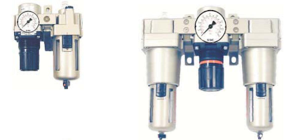
4.Pneumatic Oil and Water Separators.
a.Drain water from the filters before each shift and as required during the shift.
b.Check and fill air line lubricators (use #10 SAE nondetergent oil).
c.Check and adjust drip rate for the main pneumatic lubricator to one drop per 810 boxes.
d.Check for crazing and cracking of plastic bowls.
The monthly lubrication is variable depending the on the machine operation time and environment. Machines operating on a 24 hour schedule or in an environment containing higher concentrations of dust, dirt or debris may need to be wiped down and lubricated more frequently.
Excess or spilled lubricants can cause package damage. Spilled lubricants must be cleaned up to prevent slips or falls by personnel which may result in serious injury. Over lubricating is harmful to most components.
Lubricate lead screws, sprockets, connecting chains and gear racks weekly, or after each 40 hours of continuous use. Use lubricants B,C, and D respectively.
Note: Bearings on the feed wheel assemblies and discharge conveyor are factory sealed and need no further lubrication.
Note: Check and fill the air line lubricators on a daily basis. Use SAE 10 non-detergent oil only. Use of automotive type or detergent oils will damage the seals throughout the pneumatic system.
Note: Refer to the glue manuals for proper air line lubricator adjustments.
Note: Over time shafting may experience a build-up of contaminants. When necessary, clean shafting with a light oil saturated rag only.
Use of solvents may damage seals and cause premature failure of linear device.
Lubrication Schedule
LocationLubed ComponentFrequencyLubricant
Vacuum Pull Down Hoppers
Cylinder Rods WeeklyA
Vacuum Pull Down Hoppers Kicker Vee Guides WeeklyB
Motor Driven Components Gear Boxes
Motor Driven Components Drive Chains
Die Compression Section Die Frame Cam Bearings
Die Compression Section Die Frame Cam Bearing Slots
Mandrel and Blocker Section Bearing Rods And Linear Bearings
Refer to manufacturer’s data included with this manual
Weekly or after 40 hours of operation E
Weekly or after 40 hours of operation B
Weekly or after 40 hours of operation B
Weekly or after 40 hours of operation A
Mandrel and Blocker Section Linear Guides MonthlyA
Lubricant Codes
A10wt. SAE non-detergent oil
BLithium soap-based grease (medium consistency)
CSilicone lube spray (if possible with pinpoint applicator)
D As listed in the gear motors manufacturers data as supplied with this manual or a gear oil which meets AGMA #7 Compound Spec.
EAerosol chain and cable lubricant.
This chapter provides information on machine service including part replacement instructions, parts lists, part ordering procedures and how to use the Bill of Materials.
If the information provided in this chapter does not resolve or provide a resolution for the machine issue being experienced, please contact our Service Department at 800-732-7766. When prompted, enter 2 for the Service Department. Select the appropriate number for the service branch you would like to contact when prompted.
• Service Parts: Enter 1.
• Service Technical Support: Enter 2.
• Service Scheduling Coordinator: Enter 3.
• Service Engineering Quote Team: Enter 4.
Determine if part removal is absolutely necessary before disassembling any portion of the equipment. Refer to Troubleshooting for more information.
Before performing any machine adjustment or maintenance, close the Pneumatic Energy Isolating Valve and the Electrical Disconnect. Follow your company’s lock out tag out procedures.
For more information on removing parts, refer to the General Subassembly drawings included in the packet of drawings accompanying this manual. The bubble numbers on these drawings identify replaceable parts.
1.Before reassembling, wipe all parts with a clean dry cloth. Apply the proper type of lubricant to each working part, if necessary, being careful not to over lubricate.
Standard Purchased Parts
When available, Pearson Packaging Systems provides vendor data sheets to aid in identifying, servicing, and replacing standard purchased parts.
The Recommended Spare Parts (RSP) list for each machine is included in this manual. You can purchase the RSP at any time.
Replacement Parts
Pearson Packaging Systems will provide replacement parts for most components on your machine, including standard parts purchased from outside vendors.
a.To order any part, provide the following information:
b.Machine serial number.
c.Pearson part number.
d.Quantity required.
e.Description.
f.Purchase order number.
g.Shipping instructions.
1.To order parts under warranty, follow the steps above and provide the following information:
a.Serial number of the machine or original part P.O. #.
b.Pearson part number.
c.Quantity required.
d.Description of failure or justification for warranty replacement.
e.New Purchase Order Number (required).
f.Shipping instructions.
2.A Parts Replacement Return Authorization Number will be issued to accompany and identify the return. Parts must be returned within 30 days to remain under warranty.
The defective part will be returned to the vendor for evaluation. If the defective part is determined to be covered under the warranty, the new purchase order will be credited.
The Bill of Material (BOM), used to find part numbers and/or bubble numbers, is a listing of parts and purchased components used to assemble this machine.
The following instructions explain the layout of the BOM:
Titles and Columns
The column headings shown on each page of the BOM include Level, Sub Part/Rev, Part Description, Position, Quantity and Manufacturer/Manufacturer’s Part Number
Parts for the main machine are grouped under the main and sub assemblies that make up the machine. Examples of main assemblies include Guards (GRD), Electrical (ELE), and Modules (mechanical sections; MOD). Examples of sub-assemblies include Mechanical (BSA), Electrical Assembly (ASM) and Electrical Panel (PAN). Individual parts may be listed under a main assembly but most are listed under the sub-assemblies. Level designations are Level 1 – Main Assemblies, Level 2 – Sub Assemblies, Level 3 and 4 – Parts.
Sub Part/Rev
The part number for each machine component and the part revision number is included on the list. Use this part number when ordering spares from Pearson Packaging Systems, 800-732-7766.
Part Description
A brief description of the part, its size, color, material, etc.
Position
This column shows the bubble (position) number of a sub part with reference to the Assembly Drawing. This space is filled with an asterisk if no bubble number appears on the print.
Quantity
Indicates the total quantity of parts required.
Manufacturer/Manufacturer Part Number
Each part will have the manufacturer listed. Purchased components will also have the manufacturer’s part number listed.
3-D Assembly drawings are provided with the machine documentation. These drawings (dwf) represent the base machine configuration in fabricated parts. For machines that are built with alternate fabricated parts (i.e. stainless steel, anodized, etc) refer to the computerized Bill of Material for the alternate fabricated part numbers.
Abbreviations
Approx.: Approximately
CSL: Constant Scoreline
FBA: Fibre Box Association
Fig.: Figure
FOLF: Full Over Lap Flap
Hi-Cap Mag.: High Capacity Magazine
HP: Horsepower
hr: Hour
HSC: Half Slotted Case
HZ: Hertz
KD: Knocked Down
max.: Maximum
min.: Minimum
opt.: Optimum
Para. or ¶: Paragraph
PH: Phase
PMMI: Packaging Machinery Manufacturer’s Institute
psi: Pounds per square inch
RSC: Regular Slotted Case
SCF: Standard Cubic Foot
std.: Standard
typ.: Typical
Air Prep Unit: The air prep unit consists of a Lock out Valve, integral Filter Regulator, Soft Start Valve and an Exhaust Valve. The unit is used to filter and regulate the incoming compressed air to the rest of the system. The Soft Start Valve will slowly build the air pressure during startup. The Exhaust Valve will immediately dump the air from the system when a jam occurs, or when an Emergency Stop button is pressed.
Constant Scoreline: The machine’s constant, that when setting up, or conducting changeovers, is essential to locate the case and/or carrier material in a specific location for the equipment to operate consistently.
Cylinder Cushions: Cylinder cushions control the smoothness of the end of the stroke. Adjust the cushion so there is no hard stop and not much, if any, bounce. If a cylinder is allowed to bang or slam to a stop, the internal cushion seal will wear out. You will then need to replace the seal before you can make any further cushion adjustments.
Cylinders: Pneumatic cylinders are used to accomplish movement of parts.
Electrical Dump Valve: Safety valve that dumps air downstream of valve. Air downstream of valve is called “dumped air.” Air between Manual Dump Valve and Electrical Dump Valve is called “undumped air.”
Flow Controls: Flow control valves are used to control the amount of air to a component, affecting the speed at which the component reacts.
Fuses: An electrical safety device consisting of, or including a wire or strip of fusible metal that melts and interrupts the circuit when the current exceeds a particular amperage.
Gear Reducer: A mechanical component that changes the shaft speed of an electrical motor.
Glued Tabs: The glued joint of the case.
Half Slotted Case (HSC): A type or style of case with folding bottom flaps, but without top flaps.
Knock Down (KD): A blank case in its collapsed or flat condition. Normally how material is shipped to customers for packaging processes.
Main Air Filter/ Regulator (Combo): Protects machine components by filtering and regulating the air going into the machine. Acts as a water trap and needs to be drained and/or cleaned periodically.
Main Air Regulator: The main air regulator is an adjustable device attached to the air source of the machine. The regulator reduces the air flow to a constant rate. This is done in order to protect the components of the machine by restricting the volume at which air enters the system and to maintain air pressure at a level suitable for the devices.
Manual Dump Valve: A pneumatic energy isolating valve, required by OSHA (29 CFR 1910.147). In the exhausting position, isolates the machine from incoming main air. To prevent accidental start-ups while cleaning or servicing the machine, this valve can be physically locked out and/or labeled with a warning tag while in the exhaust position.
Motor: A device that converts electrical energy into mechanical energy using forces exerted by magnetic fields on current-carrying conductors.
Open Depth: The inside dimension of the case, from the bottom of the case to the top of the open flaps.
Photocell: A sensor used to detect either carriers or cases. Used to indicate an action has been accomplished, and that another action can now take place.
Pushbuttons: A device for opening and closing or for changing the connection of a circuit.
Reflector, Photocell: A reflective disk or strip used with a photocell to reflect a beam emitted by the photocell.
Regular Slotted Case (RSC): A type or style of case. This case will have open flaps that remain in the open or upward direction during the packaging process.
Relays: An electromagnetic device for remote or automatic control that is actuated by variation in conditions of an electric circuit and that, in turn, operates other devices (as switches) in the same or a different circuit.
RSC Tab Lock: A type or style of case. This case will have top flaps folded around the body of the case and held by tabs during the packaging process.
Score Lines: The pre-positioned indentations or perforations.
Skewing: The placement of the glued joint and if the joint is properly positioned, maintaining the design specification of the case.
Slow Build Valve: Prevents a surge of high pressure air during machine start-up. During start-up, air is allowed to enter the system slowly. When the system air builds enough pressure, the valve shifts and allows full volume through. If there is a large loss of air in the system (due, for example, to a leaking hose or a damaged air cylinder) during machine start, pressure in the system will not build and the valve will not open. The Slow Build Valve should be adjusted to reach full volume in 2 to 2.5 seconds, as the machine start delay pays out in 3.5 seconds.
Spring Loaded Ram Lock: If the machine start delay pays out before the slow build valve opens fully, the ram will try to fire; however, the lack of pneumatic pressure will prevent the ram lock from releasing. You must have full air pressure before the machine start delay pays out and the machine starts to cycle.
Switch, disconnect: A safety switch that, when turned to the “off” position, cuts the electrical power to the machine.
Switch, limit: A mechanical sensor used to detect that an action has been performed. Part of the control circuit of the machine.
Switch, pressure type, bellows: A safety switch that detects the amount of air pressure being fed to the machine. If the air pressure falls below a certain amount the machine will shut down.
Switch, proximity: A sensor that, without making physical contact, detects the presence of a metal target, within a specified range.
Switch, selector: An electrical control device that allows the activation of specific control circuits in the overall machine electrical program. Part of the control circuit of the machine.
Switch, safety, interlock: A two-part safety switch that allows the equipment to function properly when both parts are properly mated. If the two parts are disconnected (for example, by opening a guard door), power is removed from the machine.
Transformer: A device that reduces voltage in the control circuitry.
Valves: Pneumatic devices that direct the flow of air to and from other components (i.e., cylinders). Valves can be controlled electrically or mechanically.
All rights reserved. No part of this publication may be reproduced, stored in a retrieval system, or transmitted in any form or by any means (electronic, mechanical, photocopying, recording, or otherwise), without the prior written permission of:
Pearson Packaging Systems
W. 8120 Sunset Highway Spokane, WA 99224
1-800-732-7766 www.pearsonpkg.com
Pearson Packaging Systems strives to ship up-to-date, accurate manuals with our machines. However, continual product improvement does not make this possible. Therefore, this document is provided "as is" at the time of machine shipment.
Please provide your machine serial number whenever ordering parts or referencing information to ensure Pearson Packaging Systems supplies you with the correct parts for your machine.
Pearson Packaging Systems disclaims any liability or responsibility to any person for loss or damages, including but not limited to, the following: expenses, which may arise or result from the use of any information contained in this manual; fines or penalties for the violation of any federal, state, or local regulations.
Pearson Packaging Systems will not be responsible for the unsuccessful operation of any of its products that have been modified in any way by anyone other than an authorized factory representative.
No patent liability is assumed with respect to the use of this information.
Most references to manufacturers or their products are registered trade names and are to be treated accordingly.
Printed in the United States of America
About this Manual................................................................................1-1
Operator Message Boxes
In This Chapter.
Standard Option Overview.
Non-standard Options Overview
Installation Procedures
Machine Safety.
Machine Operation.
Troubleshooting
Preventive Maintenance
Service
Separate Glue Unit Disconnect............................................................3-1
In This Chapter.
Option Overview.
Installation Procedures
Machine Safety.
Machine Operation.
Troubleshooting
Preventive Maintenance
Service
3-1
3-1
3-1
3-2
3-2
3-3
This manual provides instruction on installation, machine safety, operation, preventive maintenance, troubleshooting and service procedures.
The features shown in this manual are st andard. Customer option information is referenced in the Option section at the end of this manual. Please review the Option section, if applicable, before starting up, loading, running or shutting down the machine.
The machine can be either right handed or left handed. The pictures in this manual are for reference and may not reflect the hand of the purchased machine
For the purpose of this manual, photocells, photo eyes, proximity switches, and limit switches are referred to as sensors.
Operator message boxes are used throughout the manual to bring attention to important information, cautions or warnings beneficial for safe and efficient machine operation. In some cases, the operator message boxes reflect the safety labels on the machine.
Operator message boxes include, but are not limited to, the following:
An imminently hazardous situation which, if not avoided, will result in death or serious injury.
Danger! Equipment starts automatically. Lock out/tag out before servicing.
A potentially hazardous situation which, if not avoided, could result in death or serious injury.
Warning! Moving Parts can crush and cut. Do NOT operate with guard removed. Follow lock out procedure before servicing.
Warning! Avoid injury. Do NOT operate machine without all guards in place.
A potentially hazardous situation which, if not avoided, may result in minor or moderate injury.
Pinch Points Any point at which it is possible for a portion of the body to be caught and injured between moving machine or equipment or work piece parts.
Caution A potentially hazardous situation which, if not avoided, may result in property damage (used without the safety alert symbol).
Safety Relates directly to a machine or operator safety issue or concern.
Important Information important to machine operation.
Note Additional relevant information or comments.
This chapter provides an overview, operation instructions, troubleshooting and preventive maintenance for this purchased option.
Allen-Bradley Beacon Indicator Light. Beacon indicator banks may come with the following features:
•Warning horn
•3-, 4- or 5- light bank

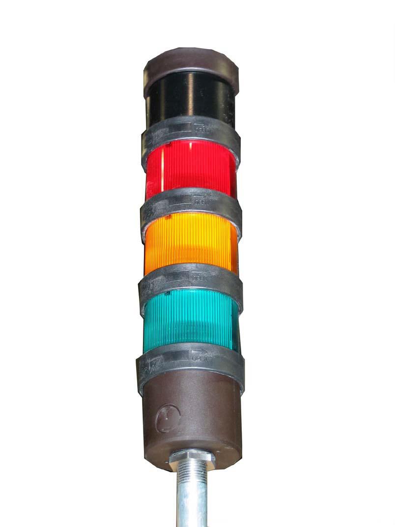
1.Beacon option, specific customer layout and functionality. Option to configure beacon option selected for customer defined layout and functionality.
2.Telemecanique warning signal horn with Telemecanique beacon indicator bank (4 or 5 light).
1.Remount the beacon indicator light.
a.The beacon light will be located inside the main electrical panel wrapped in bubble wrap.
b.Unwrap the beacon light.
c.Push the modules together at the alignment points and twist into the locked position.

Refer to the Machine Safety chapter of the manual.
1.Refer to the electrical schematic for the specific function assigned each light color.
2.Common configurations are as follows:
a.The red light illuminates when the machine is jammed.
b.The green light illuminates when the machine is running.
c.The amber light illuminates when the machine is discharge high leveled, or if the magazine is low leveled.
d.The blue light illuminates when adhesive is low.
3.An individual light may be programmed to remain solid for one function, and flash for a second function.
4.The warning horn may be programmed to sound for a set amount of time or remain on until the operator addresses the warning.
If the light fails to illuminate or flash …
1.Verify the bulb is functioning properly.
a.If the bulb needs to be replaced, unscrew the cover from the beacon.
b.Remove the bulb.
c.Insert the replacement bulb.
2.Replace the cover.
Review the Preventive Maintenance chapter of the manual.
To contact our Service Department, please call 800-732-7766. When prompted, enter 2 for the Service Department. Select the appropriate number for the service branch you would like to contact when prompted.
•Service Parts: Enter 1.
•Service Technical Support: Enter 2.
•Service Scheduling Coordinator: Enter 3.
•Service Engineering Quote Team: Enter 4.
This chapter provides an overview, operation instructions, troubleshooting and preventive maintenance for this purchased option.
Glue disconnect can be wired four different ways.
•The glue disconnect would have power supplied from the load side of the machine Main Disconnect (Default)
•The glue disconnect would have power supplied from the line side of the machine Main Disconnect
•Customer provided separate 230 VAC 3 phase electrical drop. (If this drop will be single phase, please notify Pearson.)
•Customer provided separate 480 VAC 3 phase electrical drop.
Please confirm which configuration is required.
This option is installed at the factory.
Refer to the Machine Safety chapter of the Equipment manual.
The Separate Adhesive Unit Disconnect Switch provides a separate electrical connection for the hot melt adhesive unit. This option requires a separate electrical drop by the customer.
The type of separate adhesive unit disconnect switch and location may be a standard per Pearson or be determined by the customer.
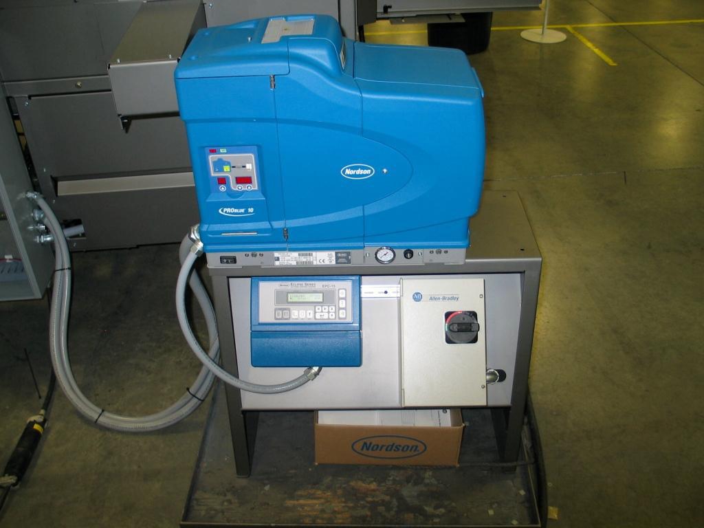
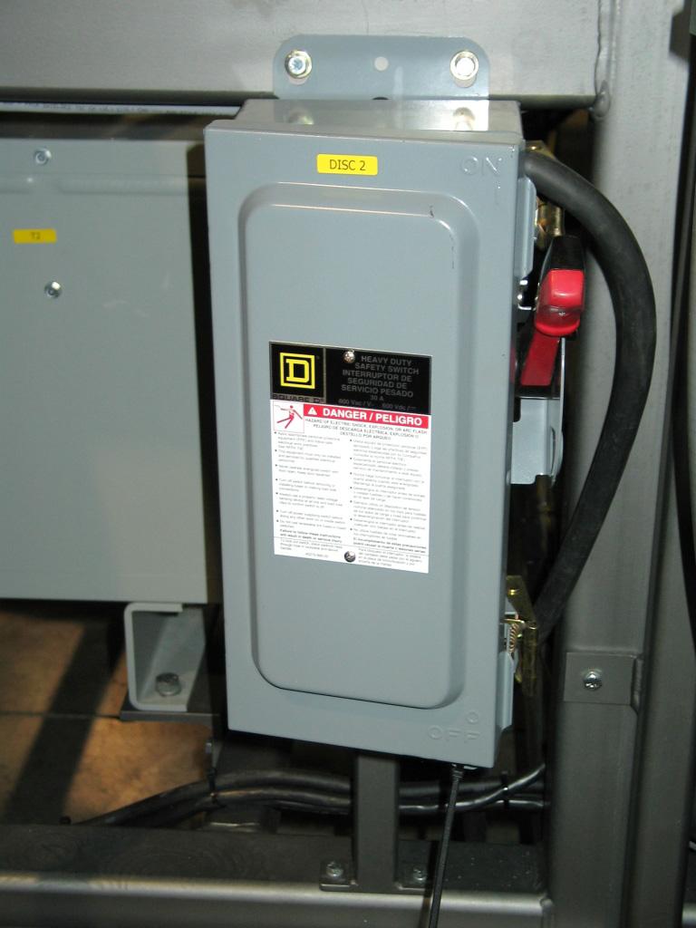
1.When performing the pre-run steps outlined in the Equipment manual make sure you include turning “on” the disconnect switch (A) on the glue unit.
Review the Troubleshooting chapter of the Equipment manual.
Refer to the Preventive Maintenance chapter of the Equipment manual.
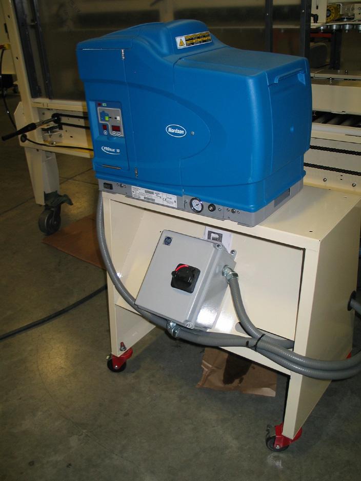
To contact our Service Department, please call 800-732-7766. When prompted, enter 2 for the Service Department. Select the appropriate number for the service branch you would like to contact when prompted.
•Service Parts: Enter 1.
•Service Technical Support: Enter 2.
•Service Scheduling Coordinator: Enter 3.
•Service Engineering Quote Team: Enter 4.
This Page Intentionally Left Blank