8 minute read
Big plans for small scale


Natural gas of fossil origin is a mix of gases where the main component is methane, which comprises between 75% - 95% of the mixture volume. The rest of the gases are ethane, propane, butane, pentanes, as well as traces of water, carbon dioxide, nitrogen, hydrogen sulfide, mercury, and others.
At the moment, natural gas is the least polluting fossil fuel, and this translates into a lower environmental impact as a result of its high hydrogencarbon ratio in its composition. This means that natural gas has a very important role in the medium- and long-term as the main energy raw material since it will allow the significant reduction of pollutant emissions.
LNG market evolution
Although in 1818 Michael Faraday managed to cool a gas resulting in the gas liquefaction procedure, it was not until the middle of the last century that liquefaction plants began to be developed at an industrial level. The natural gas market has suffered several corrections during the last 50 years, mainly due to the low price of other fuels, but the LNG market remained constant although at a low level in regions such as North America, Asia-Pacific, and the Middle East. In recent years, the LNG trade has significantly grown caused by the reduction in transport and distribution costs and, above all, due to its use for transport itself against dominant fuels in the sector such as gasoline and diesel. The prospects regarding the gas market indicate that the demand might increase by up to 50% by 2035.
Small/mid liquefaction plants
The liquefaction process consists of lowering the gas temperature down to -160˚C, resulting in a phase change from gas to liquid. With this change of state, its volume is reduced by approximately 600 times, making it much more efficient to store and transport. Both for large and smaller liquefaction plants, gas pretreatment is required before the liquefaction process. The objective of this pretreatment is to remove those impurities that could have an impact on the LNG characteristics or could solidify causing significant damage to the equipment making up the liquefaction plant. Specifically, the main impurities that must be removed are the following: � H2O, CO2, and H2S: Cryogenic processes work at much lower temperatures.
The water in these conditions either freezes solid or forms methane hydrates (H2O + methane and/or ethane). The CO2 and H2S, along with
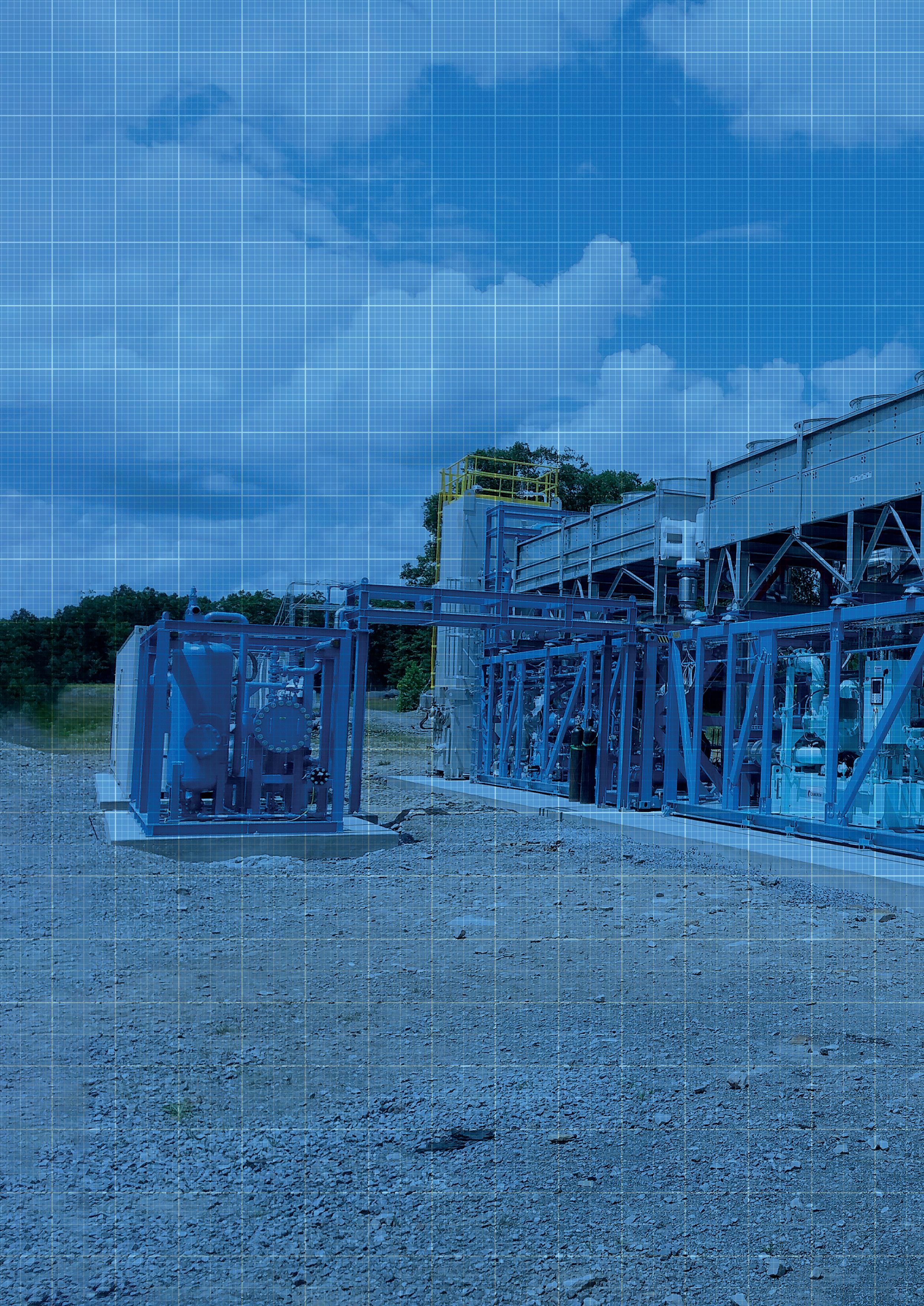
Figure 1. FNX liquefaction plant – NBC 2000.
Daniel Benavides, FNX Liquid Natural Gas, Spain, describes the growing importance of small/mid liquefaction plants for the worldwide LNG market, and demonstrates the different technologies applicable to these kinds of plants.

free water, form acids corroding pipes and other metal components. H2S is highly toxic. Carbon steel is highly susceptible to being eroded by the presence of a high content of CO2. When the gas is subject to cryogenic processes, CO2 removal is necessary because otherwise it solidifies and blocks the heat exchangers. � Nitrogen (N2): N2 content does not affect the liquefaction process, but it is an inert gas and increases transportation costs and heat absorption during the process. It also reduces the Btu content of gas. � Aromatics: Decrease the effectiveness of the gas purification processes (adsorption/absorption) and create operational problems by lacquering. � Mercury (Hg): Under the high pressures and low processing temperatures of cryogenic gas, Hg condenses from the gas phase and accumulates in the bottom of the cold box. Hg degrades aluminium alloys, causing deterioration of welds (Hg + H2O), and cracking in heat exchangers.
There are different technologies to remove these contaminants: � Absorption (liquids desiccants): Chemical absorption such as amines and potassium carbonate, physical absorption such as glycols and calcium chloride, mix absorption, and the direct conversion process (REDOX). � Adsorption (solids desiccants): Physical adsorption such as alumina, silica gel, or molecular sieve, TSA and PSA/
VPSA, and chemical adsorption such as scavengers. � Membrane permeability. � Refrigeration (condensation).
The final gas composition required before starting the liquefaction process must be as shown in Table 1.
Regarding the liquefaction technologies applicable to small/mid scale plants, there are two large welldifferentiated groups, the open loop or the closed loop type. In the open loop case, the process is based on an expansion by a Joule Thomson valve (JT valve) or a turbo-expander to achieve gas temperature reduction and liquefaction. Within this technology there are two main possibilities:
� Option A: Straight expansion. � Option B: Upstream compression stage to improve conversion rate.
It is important to mention that these types of technologies are continuously under development to increase their efficiency. For example there is the possibility to use the flash flow to cool down the inlet gas to achieve a reduction in the compressor requirements with a considerable saving of energy.
For closed loop technologies, there are different alternatives applicable to this process. On one hand, the first alternative is a nitrogen refrigeration cycle. This technology is based on the Brayton Cycle, or expander circuit, to lower the nitrogen temperature to use it to liquefy the natural gas or the biomethane. The main characteristics of this system are the simplicity, robustness, and reliability. It is even possible to improve the efficiency using the boil-off gas (BOG) to pre-cool the inlet gas or to increase the cooling stages.
On the other hand, another usable technology for this kind of plant would be a mixed refrigerant cycle, in particular a single mixed refrigeration (SMR), instead of dual mixed refrigeration (DMR), due to its simplicity and good efficiency. This cycle is based on the reverse Rankine cycle and the refrigerant composition is a mix of hydrocarbons such as methane, ethane, propane, and iso-pentane. This mixed refrigerant improves the process efficiency in comparison with the nitrogen cycle but with a significant impact on the CAPEX and with more complexity into the operational section.
Finally, within closed loop technologies, another kind of process is the cascade cycle. This system is based on a series of independent closed circuits with different refrigerant fluids such as propane, ethane, etc. The cascade cycle has a very good efficiency, but the CAPEX/OPEX is too high for a low production. This technology is used in large scale LNG plants, and for this reason it is not considered for small/mid scale plants. The FNX Liquid Natural Gas liquefaction plants’ NBC/BIO NBC/DNBC series use a nitrogen refrigeration cycle technology. This decision was made with the compromise between efficiency vs associated investment and operating cost in mind. The NBC/BIO NBC standard nitrogen closed loop refrigeration circuit is composed for the following equipment: main compressor, expander-compressor, air coolers, and a cold box main heat exchanger. The main difference with the DNBC is the integration of a two-stage expander-compressor into the closed circuit. Nowadays, to evaluate the efficiency the
Table 1. Treated gas composition
Compound Units LNG specification
Carbon dioxide ppmv 50
Hydrogen sulfide ppmv 4
Mercury µg/Nm3 0.01
Nitrogen ppmv 1.0
Butane plus (C4+) ppmv 2
Water ppmv 1
Figure 2. Fossil natural gas composition.

factor considered is the quantity of LNG produced per kWh. With FNX Liquid Natural Gas’ NBC technology, where the company could produce 28 - 56 tpd, it achieves a range of 880 - 960 kWh/t of LNG. For bigger plants where the company uses DNBC technology, it could produce 82 -164 tpd with a range of 585 - 575 kWh/t of LNG. It is important to emphasise the enhanced efficiency when the DNBC technology is considered due to the implementation of the second expander-compressor into the circuit.
Apart from these, other characteristics to help the company make the decision were the operation simplicity, robustness, and reliability. The nitrogen cycle allows the plant to work with standard process equipment for inert fluids, which also has a significant impact on both CAPEX and OPEX, and therefore becomes a very attractive option for plants below 400 m3/d LNG production.
Finally, due to the plant size, the liquefaction facility could be configured with modular structures in a finished skid format. The individual modules, which conform the complete liquefaction plant, are installed and tested in the company’s facilities, which allows them to be assembled as a plug and play format with all guarantees. Another important advantage associated with this modular design is its simplicity to transport and the small plant footprint required, which reduces the associated costs and allows FNX Liquid Natural Gas to install its plants directly at source locations, even if they are not easily accessible.
BioLNG – an emerging market
There are several factors that are pushing Europe towards increasing bioLNG production. Mainly the commitments reached for the ecological transition to reduce the carbon dioxide, the independence of fossil natural gas supply from third countries, and the increase of using LNG as reference fuel for long distance transport. BioLNG is achieved by increasing the quality standards of biomethane from biogas upgrading, through additional processing and then liquefying it in the same way as fossil fuels.
However, the main distinguishing element with respect to fossil applications is the facilities, because in this case the production will be associated with waste digestion plants, whose biogas generation flows normally shall not exceed 2000 Nm3/h.
Taking into account the implementation of different directives at a European level, emphasis is on the special importance of using gas produced from renewable energy. Biomethane has been identified as a possible solution to achieve the objectives set out in the Kyoto Treaty for the fight against climate change, establishing attractive economic subsidies for the gas. Therefore, the future scenario for bioLNG is a distributed production with a wide distribution and storage network that can be shared with existing fossil fuel facilities.
Conclusion
The clear and forceful commitment for the decarbonisation of the economy nowadays suggests that natural gas will be one of the best alternatives that exists for the transport sector. An LNG supply distribution network much more robust than the existing one shall be required, where small/ mid scale liquefaction plants shall have an important role.