
10 minute read
Leave refrigerants out in the cold


In 2018 - 2019, the LNG industry saw substantial investment in many large, conventional liquefaction projects needed to meet projected demand. However, the 2020 pandemic brought with it a glut of supply which drove natural gas demand down by 4%.1 As economies continue to recover, so too does demand for LNG. As projects become increasingly diverse in terms of geography and size, liquefaction processes continue to develop to meet customer needs for reliability, operability, efficiency, and cost. For example, in the floating LNG (FLNG) and small scale LNG markets, Reverse-Brayton (RB) liquefaction cycles, also known as gas-expansion processes, have gained acceptance.
LNG plants in arctic climates have some specific needs.2 First, the ambient temperatures can vary widely, by as much as 30˚C within a month and over 50˚C during a year. Second, the plants should be simple and robust to minimise outside operator attention. Finally, minimising plot space is important due to soil conditions and to allow weather protection to be installed.
The AP-C1™ liquefaction process efficiently responds to these needs by using an RB cycle while employing recent advances in coil wound heat exchanger (CWHE) technology. This article provides further insight as to how the AP-C1 process differentiates itself from more typical precooled, mixed-refrigerant, Reverse-Rankine (RR) cycles such as the AP-DMR™, AP-SMR™, and AP-C3MR™ processes.
The liquefaction process
The AP-C1 liquefaction process is a unique RB process that has been considered an alternative solution for a wide range of applications.3 Figure 1 shows a simplified layout of the AP-C1 process. Feed gas is sent through a CWHE where it is liquefied at high pressure to approximately -105˚C. The highpressure LNG is let down through two successive flashes, produces LNG product at approximately -160˚C, and is sent to storage. The cold gas streams generated by the successive flashes are sent to CWHEs where they are warmed against slip streams of feed gas to produce more LNG. The low-pressure, warm flash gas is sent back to feed through a multistage recycle compressor. To prevent nitrogen and non-condensable accumulation as well as to satisfy the fuel requirements, a fuel stream can be taken off at an interstage pressure from the recycle compressor.
As the name would suggest, the AP-C1 process shown in Figure 1 provides closed-loop refrigeration using feed gas as the refrigerant in an RB arrangement. The refrigerant is compressed, cooled in an aftercooler, and then split. The first portion is expanded to provide refrigeration to the precooling section of the CWHE. The second portion is sent to the CWHE precooling section, where it is cooled along with the feed and then expanded to provide refrigeration to the liquefaction section of the CWHE.


Michael Cacciapalle, Mark Roberts, Chris Ott, and Fei Chen, Air Products and Chemicals, Inc., USA, describe the advantages of gas-expansion processes and why these cycles are particularly attractive for arctic applications.
Specific power
The efficiency of different liquefaction cycles can be compared using specific power. Specific power is defined as refrigeration power required to produce one unit mass of LNG, kWh/t for example. A lower specific power indicates a higher liquefaction efficiency because less power is needed to produce 1 t of LNG. The specific power depends on many factors, including compressor and driver efficiencies, line sizes, ambient conditions, etc. In this article, to compare different cycles, specific power is normalised for each data point to calculate relative specific power. All processes are normalised using the same basis, so the relative specific powers can be compared. Also, to compare just the cycles, the specific power does not include any boil-off or tank flash recycle compressor power.
For each cycle, a design case was completed using rigorous and high-fidelity simulation software. The major equipment was sized based on the design case. Subsequent cases rated the equipment at off-design points namely where ambient temperatures were varied. Specific power for each cycle is resultant of these rigorous simulations. Figure 2 shows the relative specific power for each cycle over the ambient temperature range. Here are some key takeaways from Figure 2: First and most notably, when the ambient temperatures are approximately 10˚C to 15˚C colder than the design point, the AP-C1 process can be more efficient (i.e. lower specific power) than the RR processes. When the ambient temperature is 30˚C colder than the design point, Figure 2 shows that AP-C1 has a specific power approximately 10% better than either the AP-DMR or AP-C3MR processes. Second, while the AP-DMR and AP-C3MR processes certainly have their own distinct advantages, their efficiencies are very similar, only differing by approximately 2% in this example, even at the coldest ambient temperatures.
The AP-C1 process achieves this relatively high performance at colder temperatures due to the method of adjusting for low temperature operation. Methane is removed from the refrigeration loop, thereby lowering the compressor power requirement while also keeping the volumetric flow and head closer to design best efficiency point.
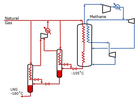
Figure 1. The AP-C1™ liquefaction process.
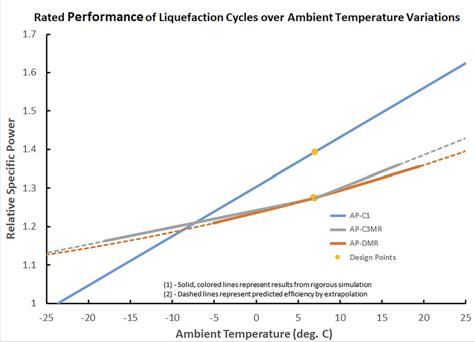
Figure 2. Liquefaction process efficiency comparison.
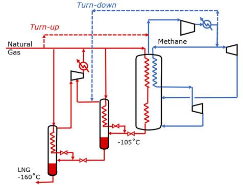
Figure 3. The AP-C1 process capacity control.
Simplicity of operation
Some of the other key differentiators for the AP-C1 process revolve around the fact that refrigeration is provided solely via sensible heat and not the latent heat of a boiling refrigerant. The AP-DMR and AP-SMR processes utilise mixed refrigerant and the AP-C3MR process utilises propane and mixed refrigerant to precool and liquefy natural gas. As liquid refrigerants are essential to operation, it is critical that composition, inventory, and condensation conditions are managed to create the required liquid refrigerants at varying ambient temperatures and production rates. With the AP-C1 process, capacity control of the refrigeration loop is very straightforward. As production increases or when ambient temperature increases, more refrigeration is required. High-pressure feed gas is sent to the suction of the methane compressor increasing the refrigerant loop pressures and therefore producing more refrigeration. Conversely, for reduced capacity or when ambient temperature is lower, less refrigeration is required. The refrigerant loop can be de-inventoried back to the feed which decreases the refrigerant loop pressures and produces less refrigeration. The ability to recover the methane refrigerant as LNG during turndown reduces or eliminates flaring during capacity adjustment and shutdown. Figure 3 shows how the methane refrigeration loop is inventoried and de-inventoried.
Use of aeroderivative gas turbines as drivers for the methane refrigeration compressor and the end flash recycle compressor provides more operating flexibility because the
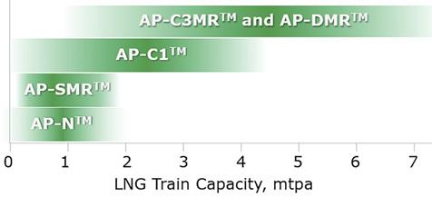
Figure 4. Train size comparison.
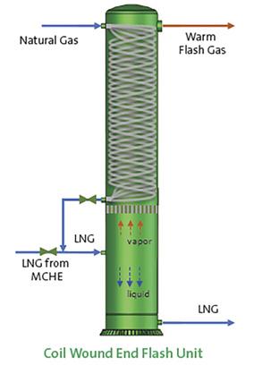
Figure 5. Integrated end flash unit.
drivers have a wide speed range. When production must be reduced for short periods of time, the refrigerant inventory can be kept constant by slowing the aeroderivative gas turbine and their associated compressors. This produces less refrigeration and therefore produces less LNG while keeping each compressor operating near its maximum efficiency point. This is compared to a fixed speed driver which has limited turndown capability before the compressor must be recycled. Below that flow, the power does not decrease.
No refrigerant production or storage required
The implicit advantages of all-vapour methane refrigerant are: no requirement for importing or fractionating refrigerants for make-up, no storage requirements, and very low flammable inventory. Arctic LNG opportunities are often in remote locations so eliminating the need for hydrocarbon refrigerant importation is very attractive for lean gas. For rich gas, while hydrocarbon refrigerants can be fractionated from the feed, reducing the field construction and operational complexity of a fractionation unit and storage is likewise attractive. Any liquid formed in the refrigeration loop upon start-up would be knocked out downstream of the cold expander before entering the cold end of the CWHE. These liquids would be sent to the LNG product.
Should the feed be very rich, hydrocarbon removal may be desirable to meet product LNG heating value specifications, in this case a much simpler heavy hydrocarbon removal fractionation system may be appropriate.
Train size
The defining characteristic of the AP-C1 process is that the refrigerant is all-vapour. While there are many advantages to this, there are also some limitations that should be considered for project-specific requirements. All-vapour refrigeration means that the shellside of the CWHE is entirely vapour and requires more flow area compared to a liquid, boiling refrigerant. Larger flow area coupled with the typically higher operating pressures of the methane refrigeration loop reduces the achievable heat exchange duty per unit of CWHE, pushing the design envelope for CWHE technology if large single-train capacity is required. A single-train capacity in excess of 4 million tpy in hot climates is feasible with the AP-C1 process, although some parallel equipment may be required. Figure 4 shows the approximate maximum single-train capacity for each of the liquefaction cycles discussed. Note that the AP-N™ process, while not discussed here, is a similar RB cycle where the refrigerant is nitrogen rather than methane.
Adapting CWHEs for the AP-C1 process
There are two end flash exchangers in the AP-C1 process that economise cold, low-pressure flash gas against fresh feed to produce more LNG. Since the duties of these CWHEs are much lower than the main exchanger, they are much smaller in diameter. Plot space optimisation may often be required when configuring the overall layout for these exchangers, vapour liquid end flash drums sized for low-pressure vapour flow, and the accompanying large bore piping. Recent advancements have made it feasible to integrate a CWHE with end flash drums. Rather than having a flash drum for vapour-liquid separation, the disengagement now takes place within the shell of the CWHE. Integration also reduces plot space and large bore piping runs.4 Figure 5 shows the proposed arrangement for the integrated end flash unit.
Summary
The choice of liquefaction process is undoubtedly multifaceted and requires a detailed evaluation of all project needs. There are many cycles – such as precooled, mixed refrigerant AP-C3MR, AP-SMR, and AP-DMR processes – that will produce LNG reliably and efficiently. However, gas-expansion cycles such as the AP-C1 process should also be evaluated as its unique features may better meet project-specific goals.
This article shows that gas-expansion cycles can provide significant power savings when operating at ambient temperatures well below the design point. Additionally, the process is operationally simple and flexible, especially operating in climates such as the arctic where monthly and annual ambient temperatures change significantly and rapidly. These features make it particularly attractive for arctic applications.
References
1. IEA, ‘Gas 2020 - Analysing the impact of the COVID-19 pandemic on global natural gas markets’, 2020. 2. SCHMIDT, W. P., OTT, C. M., LIU, Y. N., and WEHRMAN, J G.,
LNG-17, ‘Arctic LNG Plant Design: Taking Advantage of The Cold
Climate’, 2013. 3. ROBERTS, M., et.al, Gastech 2018, ‘Liquefaction Cycles for Floating
LNG: From Concept to Reality’, 2018. 4. OTT, C.M., Beard, J.D., and Pearsall, R., Gastech 2018,
‘Debottlenecking: Getting the Most Out of Your LNG Plant’, 2018.


