2014/15AdvancedInteractionBARCELONAMASTERINADVANCEDARCHITECTURETouchMediaOrionCampos

2
3 MASTER IN ADVANCED ARCHITECTURE Thesis Project Title: Touch Media
Director:
Carlos Gómez Author: Orion Gorrão Moreira Campos Research Line: Advanced Interaction BARCELONA
4
5 Thanks for the shared knowledge to: Carlos Gómez Ángel Muñoz Ramin Shambayati Guillem Camprodon AlejoGabrielHegouaburuPasetti Especial thanks to my great friends: Eel Tseng Prawit Kitticharnthira Dedicate with love to: My mother, my father and Júlia
6
7 01 Sumary 02 Technological Research 02 | 01 Beggining o Globalization 02 | 02 Telecomunication Revolution 02 | 03 Digital Revolution 02 | 04 Democratization of Technology 02 | 05 Current Eletronic (Visual) Devices 02 | 06 Conclusion 03 Conceptual Research 03 | 01 We have never Touched Anything 03 | 02 Conclusion 04 Biological Research 04 | 01 Touch Sense (Somatic Sense) 04 | 02 Homunculus 04 | 03 Conclusion 05 Similar Devices 05 | 01 Currently use of Vibration in Comunication Devices 05 | 02 Vibe-ing 05 | 02 Conclusion 06 Process06 | 01 Initial Concept 06 | 02 Electronic and Coding Tools and Methods Used 06 | 03 Electronic and Coding Evolution 06 | 04 Circuit Board Project and Method of Fabrication 06 | 05 Circuit Board Evolution 06 | 06 Hardware Method of Fabrication 06 | 07 Hardware Evolution 07 Final Prototype 08 Final INDEXConclusion
Sumary01
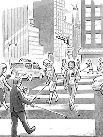
2. Movement disabled people, or long distant relation users which want to experience another type of connection that the visual devices cannot create.
3. People who want to experience and receive other types of information that couldn‘t been send by visual comunication devices.
This research aims to create a new way of comunication using and increasing our sense of touch by creating a wearable tool, which has an open use, but in this research will focus to give a critical answer to our major visual based society and the concept that we never touched Theanything.main areas where this new form of comunication can be used are:
1. helping vision disabled people, which could then could have another option to comunicate other than the braille language, since it is a form of comunication that is not open for an instant answer.
This project is the result of six months of teo retical research and three months of complete dedication at the research line Advanced Inter action, as part of the Master of Advanced Architecture program at the Institute of Advanced Architecture of Catalonia.
9
11 ResearchTechnological02
.
12
Globalizationof02|01
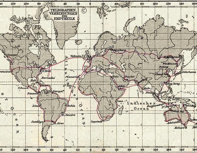
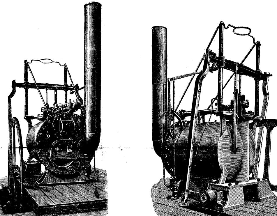
We live in a period based on the transfer of inInformationformation. always played an important role in the development of a civilization, and since the start of the globalization, which has started by the period of the great navigations in the 16th century, has started with a extremelly fast speed with the help of inventions made during the Industrial Revolution of the 19th century. Those inventions were based on the research of previous fields of physics, chemistry, and engineer knowledge in the 18 century, as the development of the steam engine and the research of electricity, which later helped the creation of the Steam Locomotive (Richard Trevithick, 1804) and the Electrical Telegraph (Francis Ronalds, 1816), which both of them contributed to the increase of comunication and connection in the world. The Electrical Telegraph, or just telegraph, can be concidered the first telecomunication de vice, and in a matter of decades after it crea tion, electrical telegraph networks permitted people and commerce to transmit messages across both continents and oceans almost in stantly, with widespread social and economicimpacts.Begining
MajorBottom:telegraph lines in 1891
Trevithick’sTop: No. 14 engi ne, built by Hazledine and Company, Bridgnorth,1804, one of the first high-pressu re steam engines.
13
RevolutionTelecomunicationsimultainously
“Telecommunication occurs when the exchange of information between two entities (communication) includes the use of technology. Communication technology uses channels to transmit information (as electrical signals), either over a physical medium (such as signal cables), or in the form of electromagnetic waves” Wikipedia, April, 8, 2015.
14
It was used transmitting electric charges, that would be translated into movement by the te legraph, and wih the wireless comunication, that started on the beggining of the 20th cen tury, it reached more distant people with less infrastructure required. Examples are the radio stations that would translate sound into eletro magnetic waves, that would later be captured and translated into movement of a vibrating surface, as a speaker on the radio equipment, which had a major and important development in rural areas arround the world. The same principle was used by the telephone, which enabled people to talk
02|02
Since the Industrial Revolution, comunication is mainly done by electronic devices, that works by electricity, which is a form of energy resulting from the existence of charged particles.
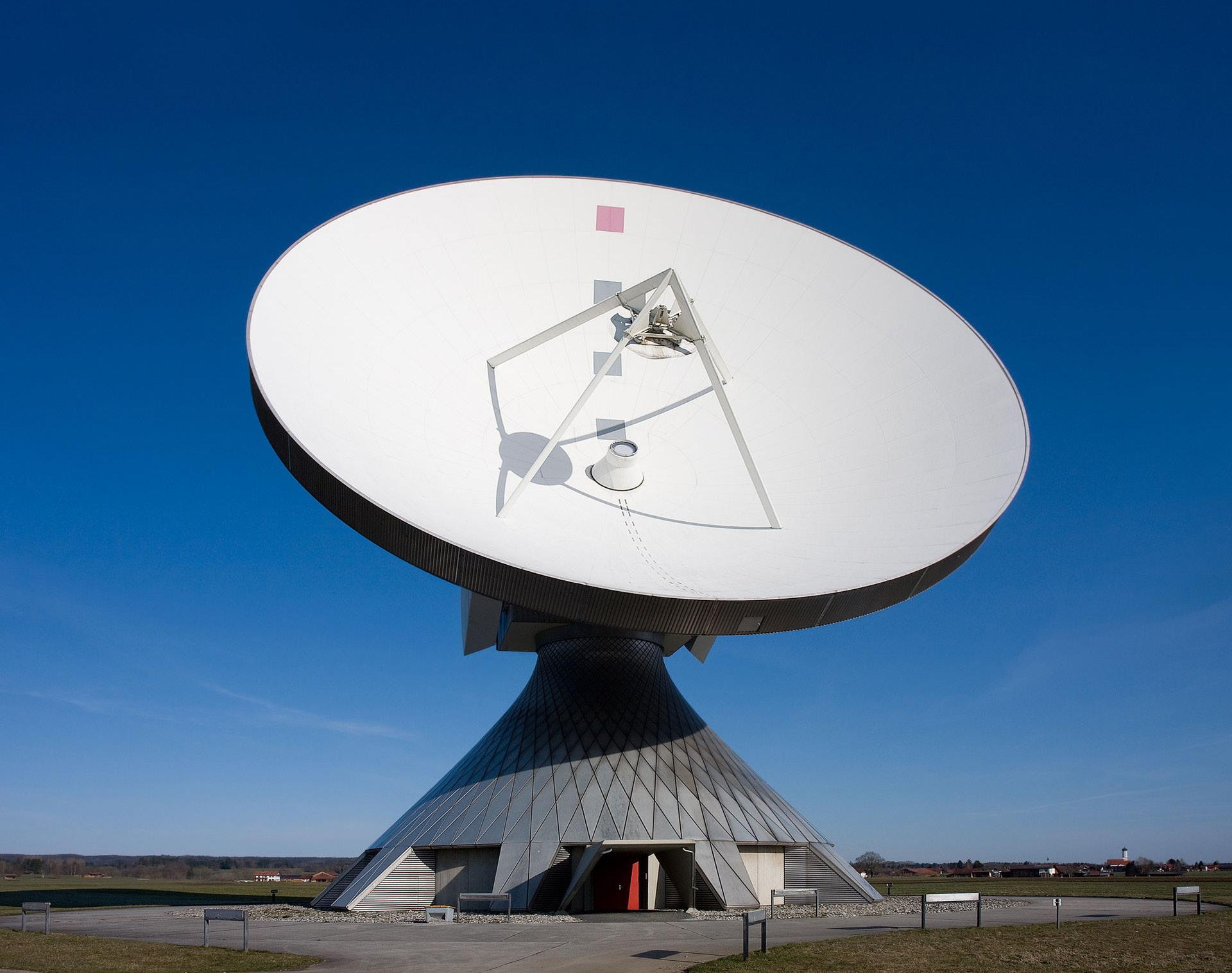
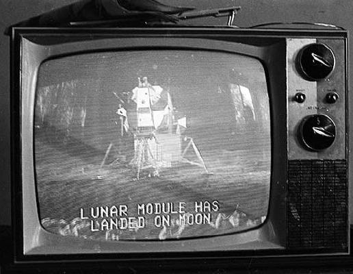
15 to each other and with the use of sattelites in orbit arround the world, could reach a bigger area. Satellites were used also for the television which now could send it information over seas and almost instantly, and started a new period of mass comunication, now made major by images.
ATop:satellite communication antenna at the biggest facility for satellite communi cation in Raisting, Bavaria, ABottom:Germany.picture of the landing of the first humans on moon, made during the Cold War, and broadcasted to all the world.
16

AfterGermans.theachievements
17
Later, with physical development of micropro cessors, the computation moved from a me chanical issue to a mainly electronical issue, which helped to miniaturize the computer, to the micro scale, which lead to the creation of the personal computer by apple in the 80’s at an affordable price. Revolution
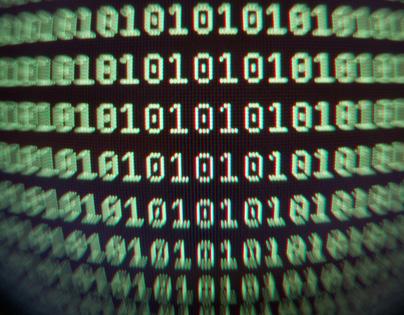
of Turing setting the begginig of computtation thinking through the use of logical deduction or the binary system, the “yes” or “no” method, the computation started to develop to more complex languages.
Digital
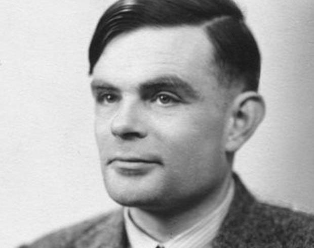
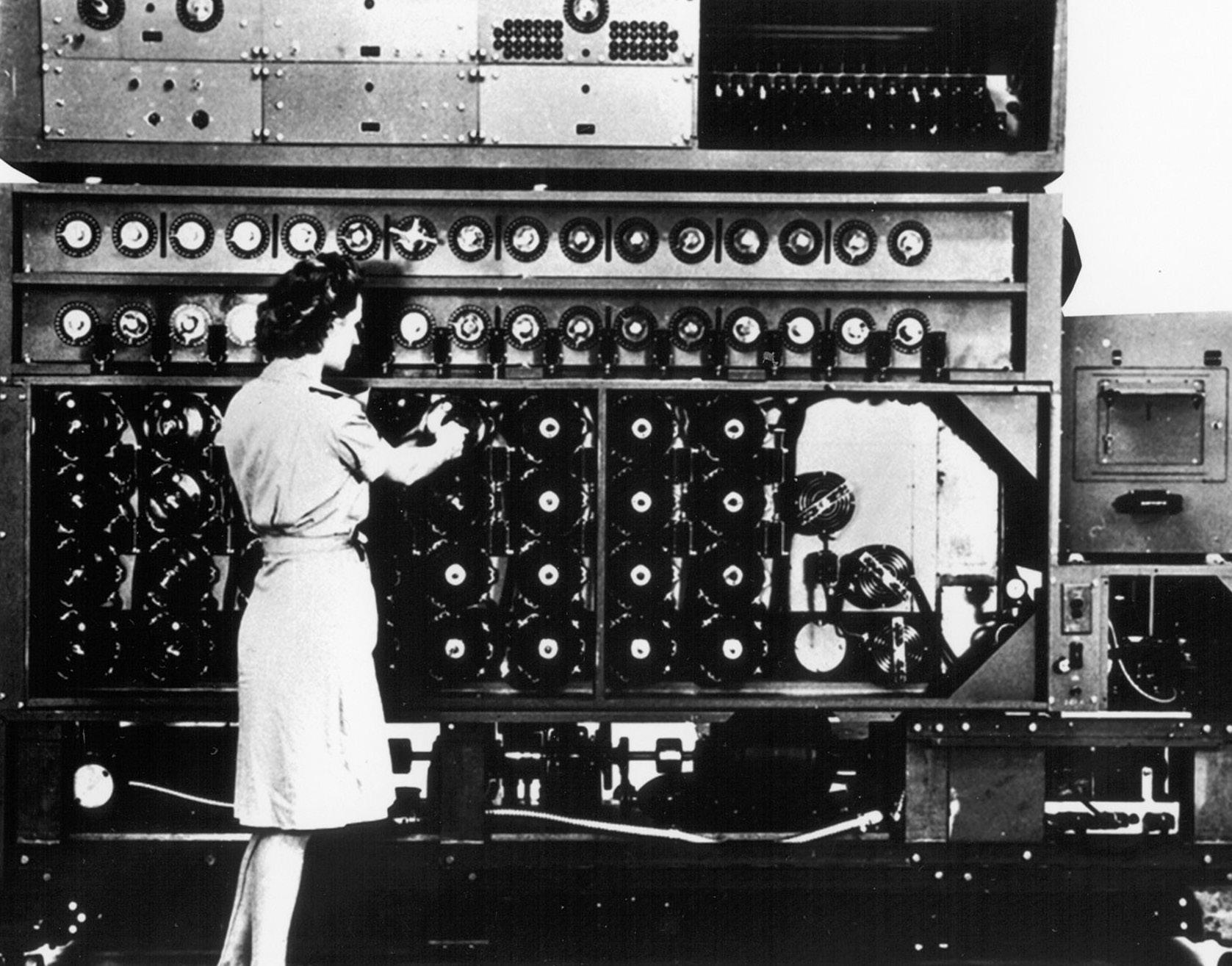
father of computation thinking. Bottom left: The bombe was an elec tromechanical device used by British cryptologists to help decipher fordablethethisputersmicroWithBottomBinaryTopWorldtedEnigma-machine-encrypGerman-secretmessagesduringWarII.right:thinking.right:thedevelopmentofprocessors,thecombecamesmallerandcausedadecreaseinprice,makingthemaf-forhomeuse.
During the Second World War, Turing worked for the Government in Britain’s codebreaking centre. For a time he led Hut 8, the section responsible for German naval cryptanalysis. He devised a number of techniques for breaking German ciphers, including improvements to the pre-war Polish bombe method, an electromechanical machine that could find settings for the Enigma machine, which later helped the British and the Allieds to win the war against the
02|03Topleft:AlanMathisonTuring,
Alan Mathison Turing was a british pioneering computer scientist and mathematician who is considered to be the father of theoretical computer science and artificial intelligence.
18
19

20
TechnologyDemocratization90’s,of
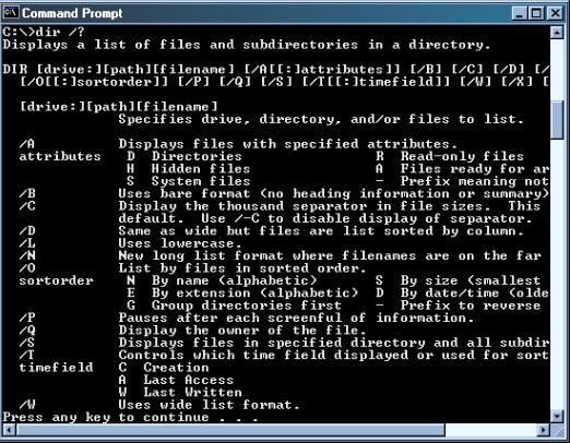
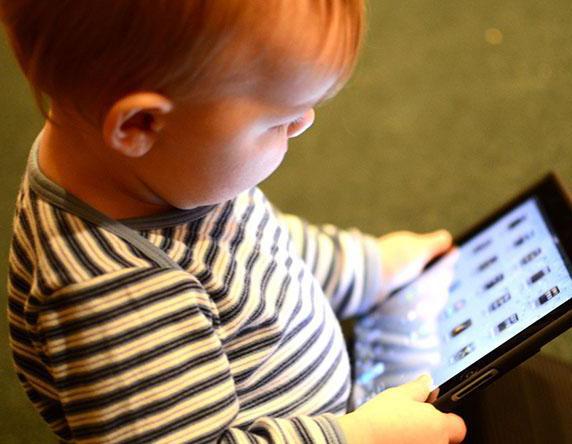
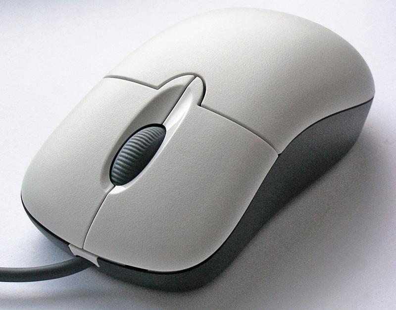
The democratization of computers among commom people of the society during the 80’s, occured not only by the decrease of the price of the Duringcomputers.the70’s and 80’s, companies like IBM and XEROX produced personal computers with an interface that demanded a bigger understanding of the logics in which the softwares were working. The common “Prompt Line” were common among the computers at this period where the only interfaces of the computer where a screen monitor and a keyboard. One of the main changes that ocurred in personal computers democratization was the implementation of the mouse in 1984 in the Macintosh 128K, which included an updated version of the original Lisa Mouse and the Ata ri ST in 1985 and in In 1982, when Microsoft made the decision to make the MS-DOS pro gram Microsoft Windows mouse-compatible and developed the first PC-compatible mouse. Those changes made easier for the user access the information of the computer. Another mainly change on the personal compu ters was the democratization by the creation of the touchscreen, which started to be inserted in cellphones and computers in the
02|04
21 but only became comercialy sustainable with the release of the NintendoDS in 2004. Until recently, most consumer touchscreens could only sense one point of contact at a time, and few have had the capability to sense how hard one is touching, so this shows how the technology is still under development, altought is widely use in the majority of comunication technologies that we have. Altough all those devices helped to democra tize this technology among non specialists, it created a generation of users, who don’t have even a basic idea of programing.
Top Typicalleft: MS Dos Comand Prompt, with the only in terface available being the keybord and screen.
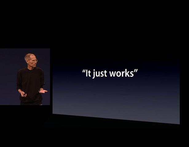
Top Typicalright:computer mouse Bottomdevice. left: Young users are alredy born in the visual touch screen world. In the image, an Ipad, a computer with a touch screen, first released in Ap ril 3, TheBottom2010.right:answerof Steve Jobs to people who ask how Apple computers works, saying that “you don’t need to worry about this, because it just works”.
22
23
24
creationuseAlso,mobile_phones_in_use)org/wiki/List_of_countries_by_number_of_(http://en.wikipedia.theamountofdataandthemorediaryofthosedeviceshasincreasedwiththeuseofthesocalled“socialmedia”.CurrentEletronic(Visual)Devices
The portability of personal computer had increased at a fast pace, and today there are avai lable smartphones, tablets, and other devices which gathered in one tool different functions of comunication, with a increasead cabability of processing information. Those devices play videos, music and do multitask actions better than the home computers of the previous decade, and they can fit into your pocket, your face, or your wrist. The number of those portable comunication devices increased at the last years, due to the low price. In countries like Chine, U.S.A., or Russia, there are 93.2, 103.1, and 155.1 cellphones for each 100 habitants 02|05
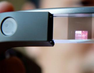
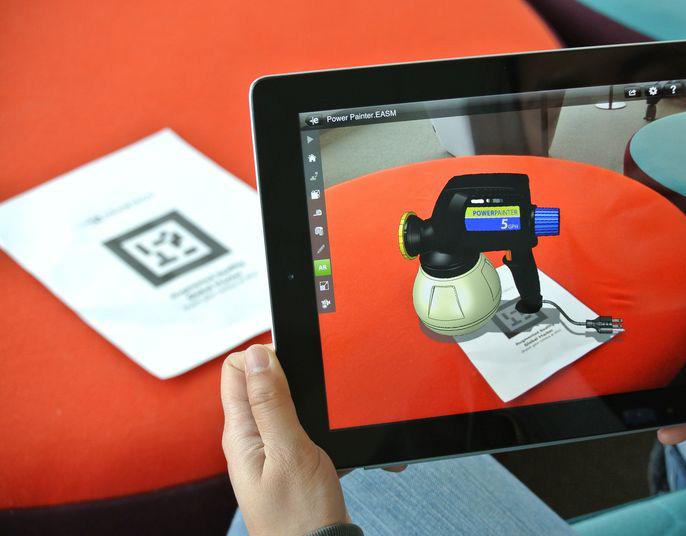
GoogleBottom: Glass, an attempt made by the Google Com pany to create a new way of using the smartphone, with the use of augmented reality, but still, a visual device.
TheTop: use of augmented rea lity apps or devices is beco ming more popular.
25
26
Conclusion02|06
All those digital and portable devices, that in recent years had become the default way of interaction with the world had been used to build an extremely rich and complex virtual enviroment. This virtual enviroment has been so sucesfull in gathering information that is slowly being concider as the main enviroment. This digital reality has characteristics that need to be concidered. Other than the political, the enviromental, and the economical aspects of this new way of intercation, there is a need of discuss the way of interaction with this devices, the relation with our body and with our senses.
27
29 Conceptual Research03
We Have
-
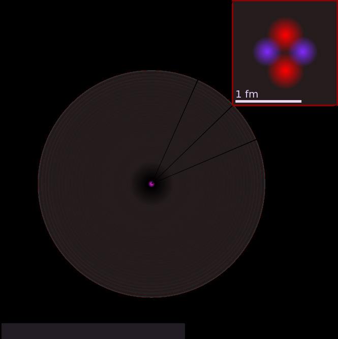
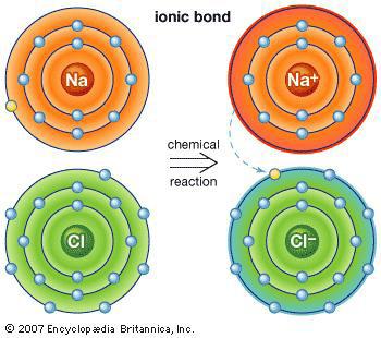
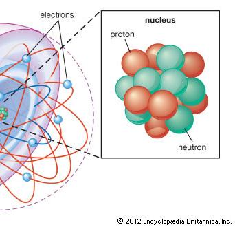
Touched Anything03|01 PhysicistTop: Michio Kaku explaining this concept at reaction.othertomssaltFormationBottomABottomwatch?v=OBZr1qmsQ0Utps://www.youtube.com/htleft:Helliumatom.right:ofthecommonmadebythetwoatthatdonttoucheacheveninthechemichal
30
All the objects from everyday life that we can bump, squeeze or touch are composed of atoms. This atomic matter is in turn made up of interacting subatomic particles, as a nucleus of protons and neutrons, and an orbiting cloud of electrons. Although these particles exist in enormous quantities, matter is mainly made by emptiness. This occurs because the size of tho se particles are extremely small in comparison with the space between them. And since matter is mainly made of empty space, it would be expected that everything could pass through each other, that human beings could pass through walls or travel along rocks. This doesn’t occur because although the space between those particles is an empty space, it is filled with electric fields that make this atom stable, and has this electric field that repulse each other. So an object which appears to be solid is actually made of subatomic particles that orbit in a electric field that repulse each atom to a speci fic distance, but never touching each other. In this sense, we never had touched anything, since even the matter that we are made, is made of atoms floating in an electric field. Never
31

32
It is physical proved that attoms don’t touch each other, only in extreme situations as radi oactivity transformations or nuclear explosi However,ons. it is poetic valid to try to increase our sense of touch, trying to at the end touch so mething with this
Conclusiondevice.03|02

33
35 Biological Research04
The somatosensory system is a complex sensory system. It is made up of a number of different receptors, including thermorecep tors,photoreceptors, mechanoreceptors and chemoreceptors. It also comprises essential processing centres, or sensory modalities, such asproprioception, mechanoreception (touch), thermoception (temperature), and nociception (pain). The sensory receptors cover the skinand epithelial tissues, skeletal muscles, bones and joints, internal organs, and the cardiovascular Althoughsystem.
(SomaticTouchlocation.SenseSense)04|01
-
Bottom NervousRight:sistem of the body.
touch (also called tactile perception) is considered one of the five traditional senses, the impression of touch is formed from several modalities including pressure, skin stretch, vibration and temperature. In medicine, the col loquial term “touch” is usually replaced with “somatic senses” to better reflect the variety of mechanisms involved.
36
The system works when activity in a sensory neuron is triggered by a specific stimulus such as pain, for instance. This signal then passes to the part of the brain attributed to that area on the body—this allows the stimulus to be felt at the correct
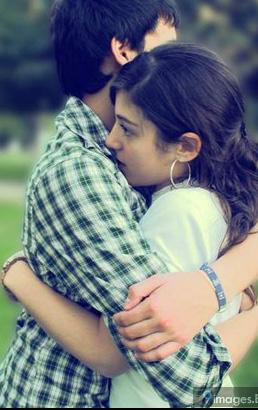
TicklingTop: is the act of touching a part of the body so as to cause involuntary twitching movements and/ or AlsoBottomlaughter.left:ahug is a touch that causes good sensations.
37


The somatosensory system is a complex sensory system. It is made up of a number of different receptors, including thermorecep tors,photoreceptors, mechanoreceptors and chemoreceptors. It also comprises essential processing centres, or sensory modalities, such asproprioception, mechanoreception (touch), thermoception (temperature), and nociception (pain). The sensory receptors cover the skinand epithelial tissues, skeletal muscles, bones and joints, internal organs, and the cardiovascular Althoughsystem. touch (also called tactile perception) is considered one of the five traditional senses, the impression of touch is formed from several modalities including pressure, skin stretch, vibration and temperature. In medicine, the col loquial term “touch” is usually replaced with “somatic senses” to better reflect the variety of mechanisms involved.
38
The system works when activity in a sensory neuron is triggered by a specific stimulus such as pain, for instance. This signal then passes to the part of the brain attributed to that area on the body—this allows the stimulus to be felt at the correct
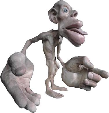
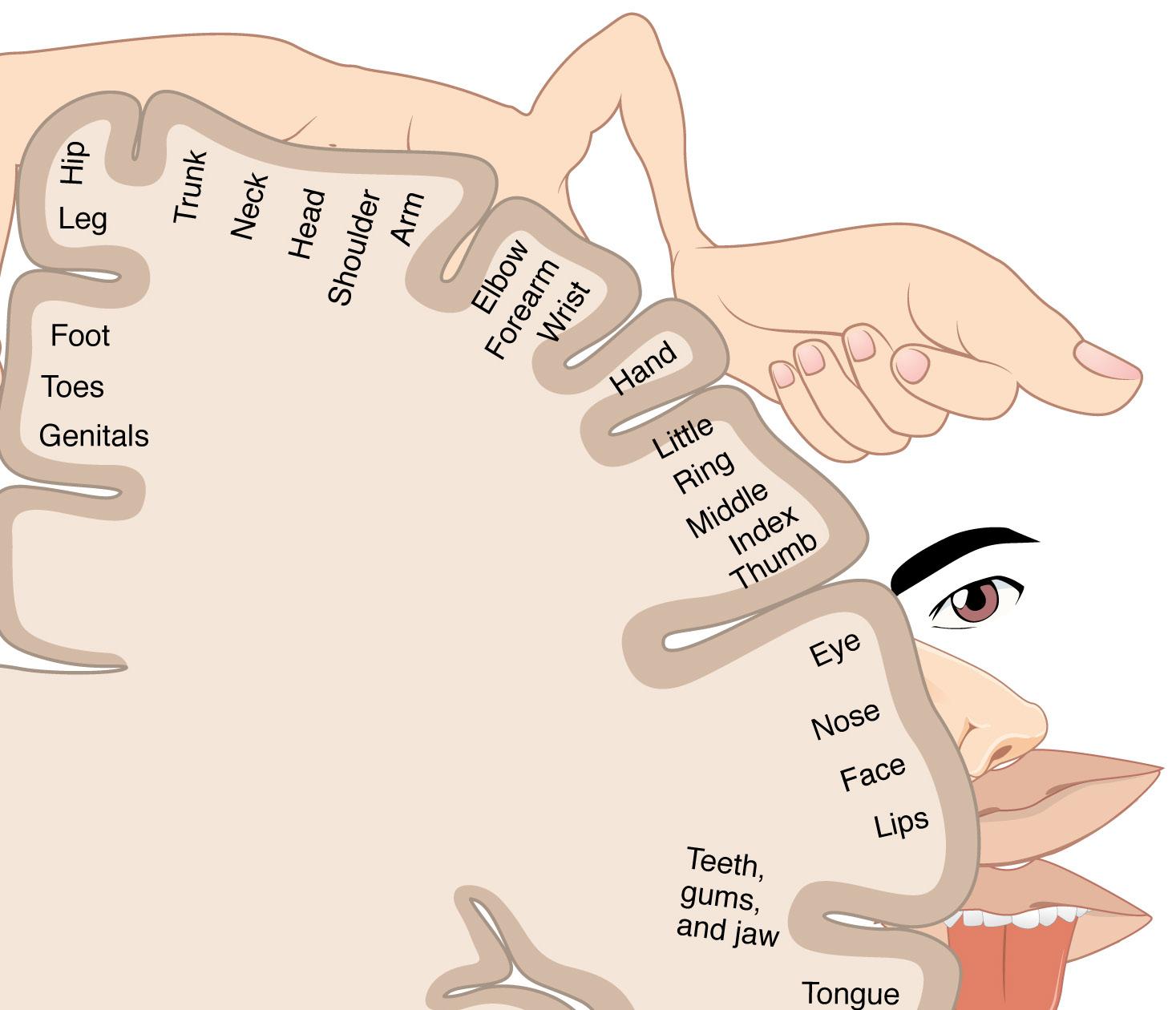
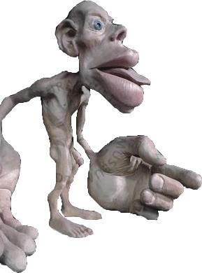
Homunculuslocation.04|02
ABottom:representation of the size of the human body based on the number of neuron’s endings.
TheTop: idea of the cortical ho munculus was created by Wilder Penfield.
-
39
40
Due to the big amount of Neurons endings on the hands and fingers are the biggest in the whole body (each finger has the same amount of neurons of both legs), the regions where the devices would be installed will be the hands and in the back. This last one because of the big area available for the second part of the device.
Conclusion04|03
41
43 Similar Devices05
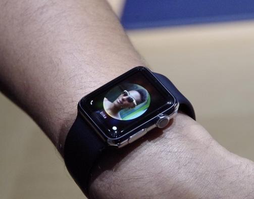
TheTop: Apple Watch and it mains difference from other smartwatches, it buzzes eloquently via haptic feedDurr,Bottom:back.a watch designed by Theo Tveterås and Lars Mar cus Vedeler whch vibrate each five minutes.
Currently Use of Vibration in Comunication Devices05|01
44
Vibrating devices are already used widly in cellphones and smartphones, but all of them use this ability as a secondary way of informing something. Usually users only set this way of comunication together with others types, as visual or audio. The iPhone takes it a bit further and allows for customizable vibration notifications—i.e, if some person is calling, the user get a rapid burst of buzzes or a few long vibrations. The new Apple Swatch also do this, and since it is directly in contact with the skin, it has broader possibilities of being the main way of informing the user.
Other than cellphones, the vibration action is being used also in watches, as the Durr watch, which instead of a visual way of inform the pass of time, is a collorfull disk that vibrates each five minutes.
45

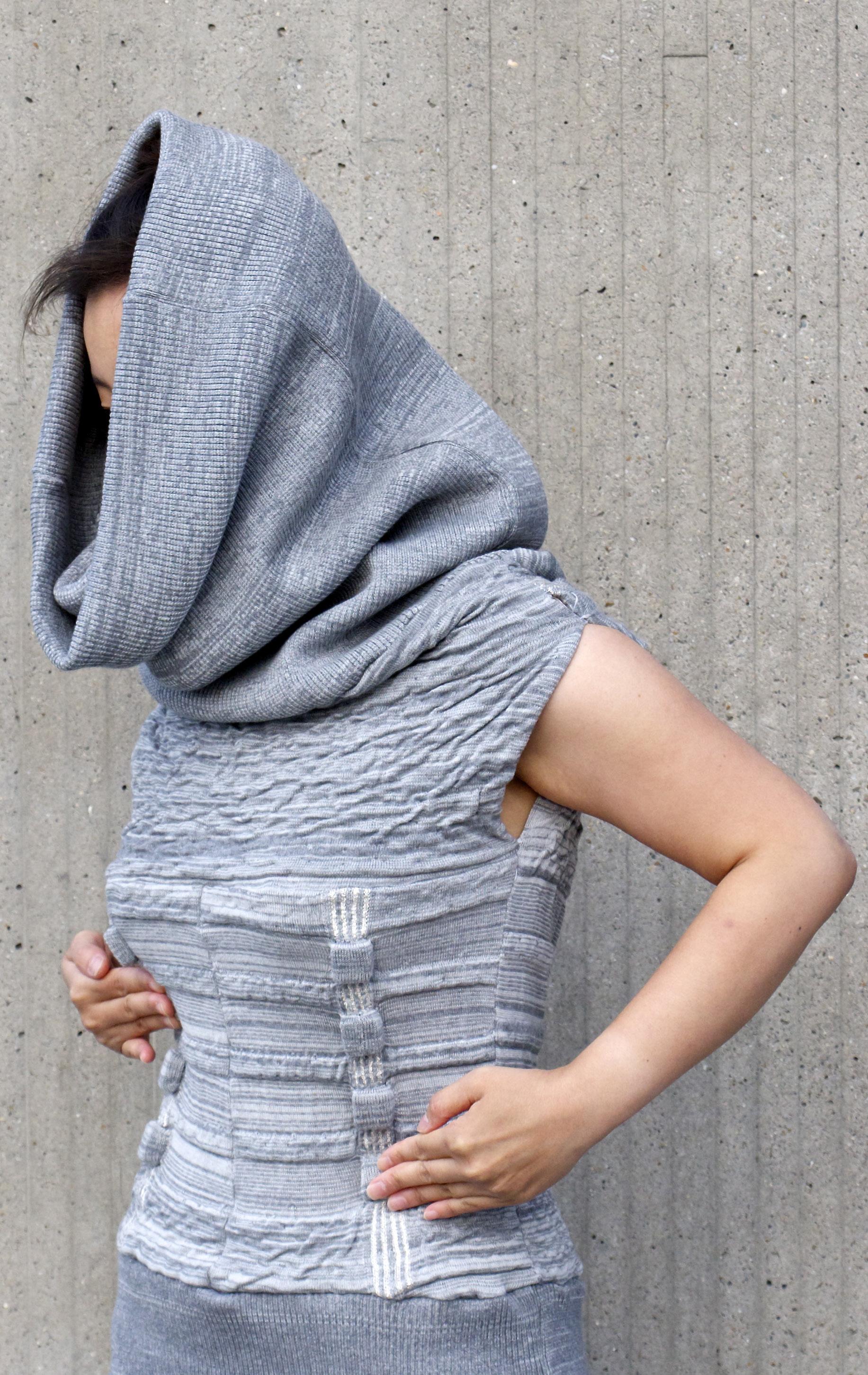
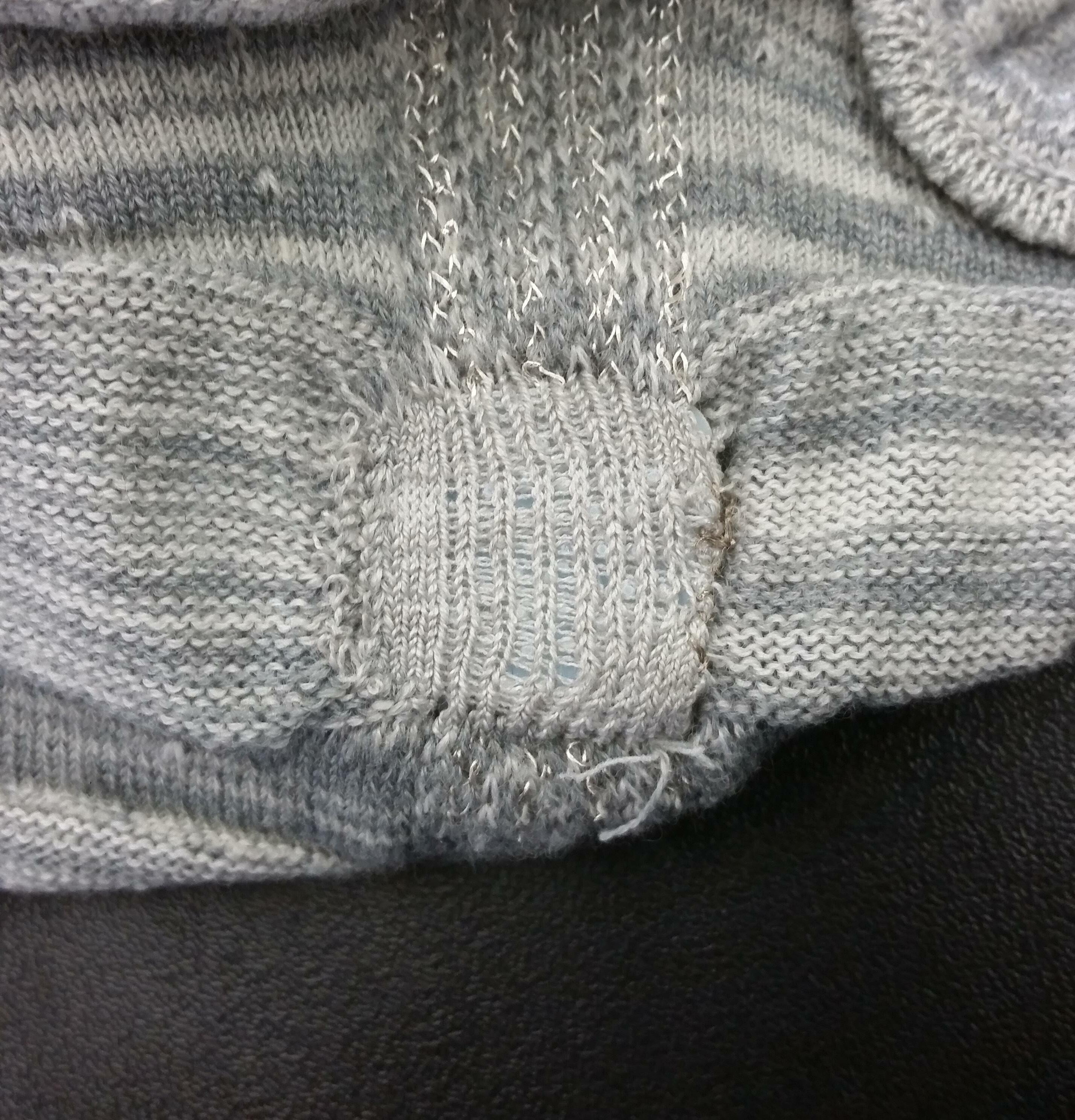
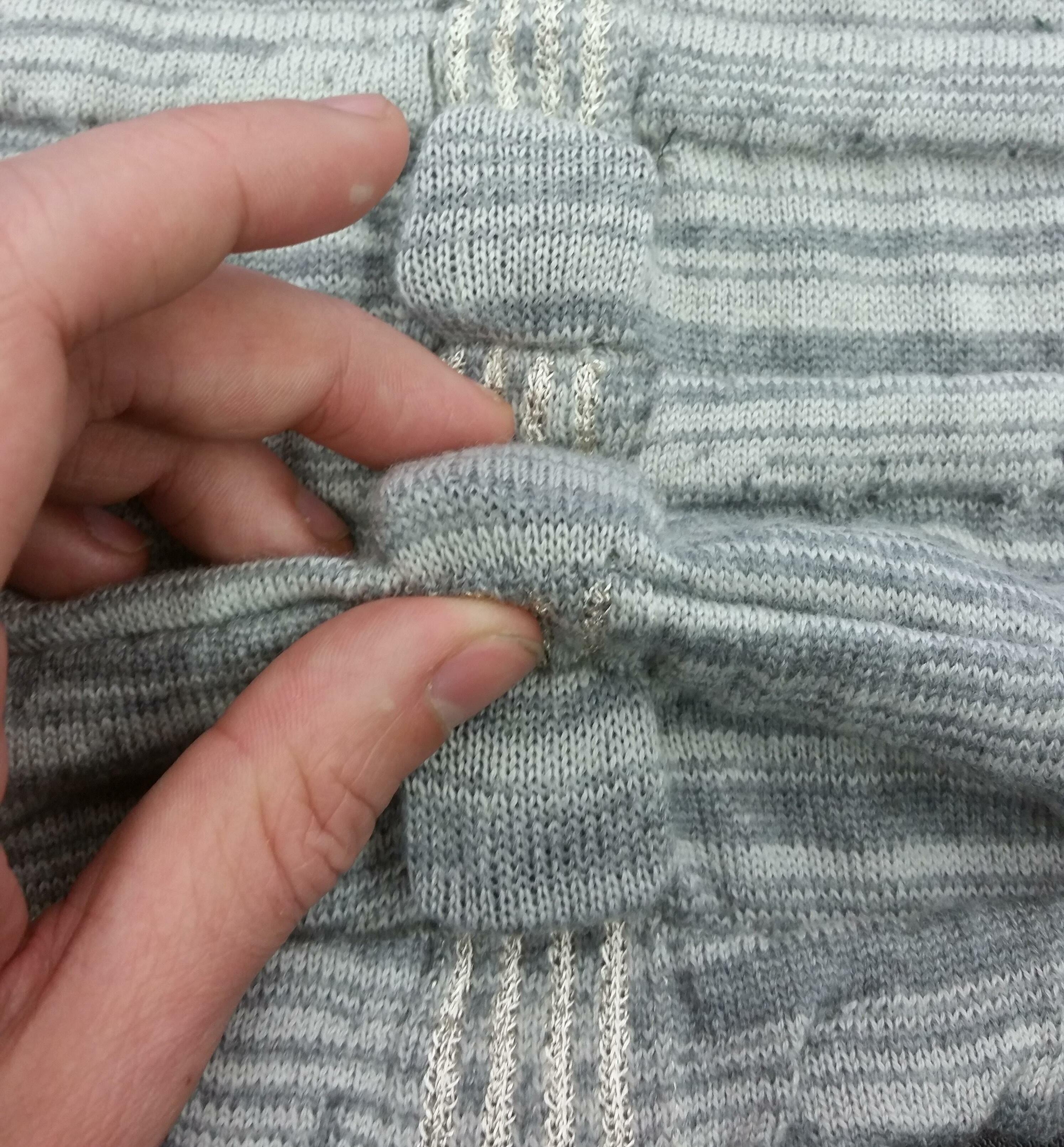
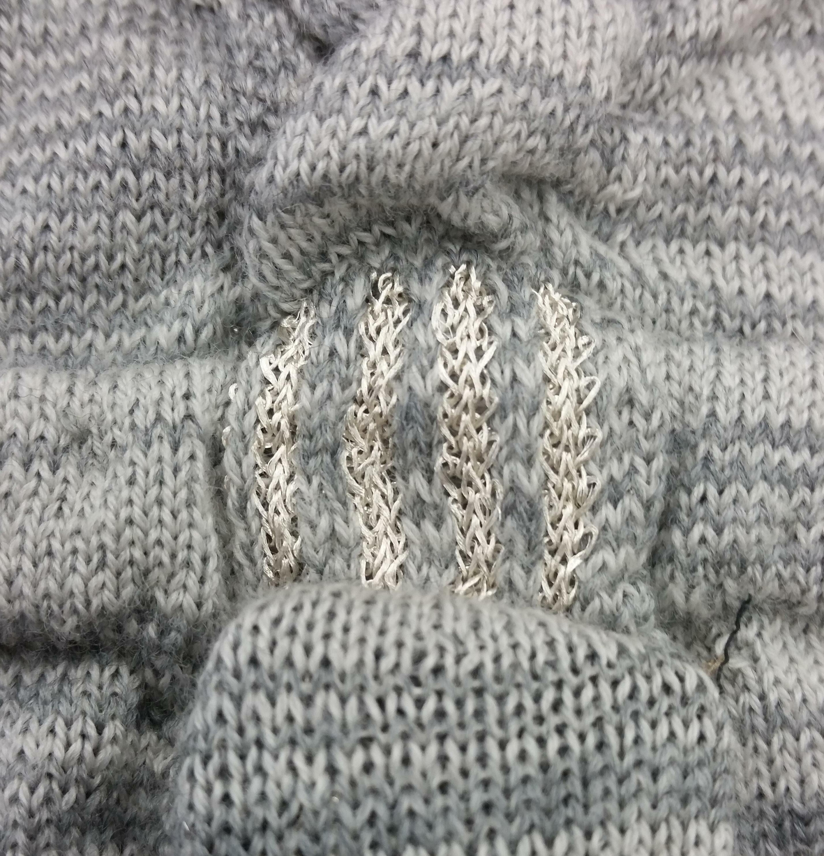
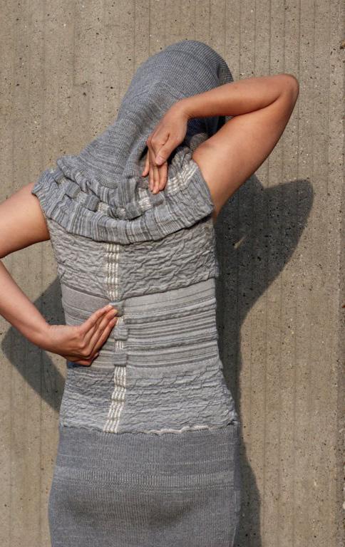
Vibe-ingbody.05|02 ImagesRight:
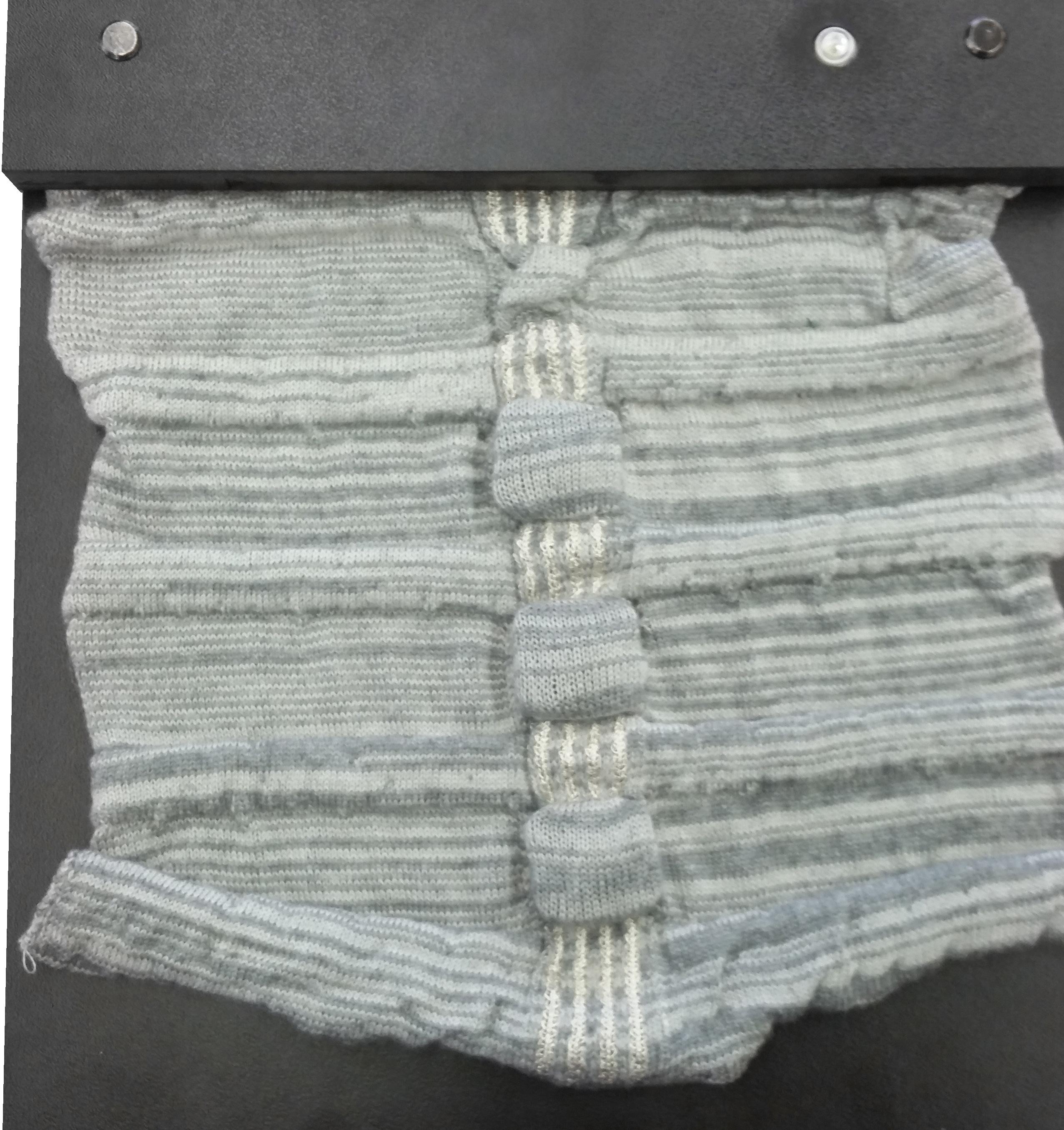
Vibe-ing is a self-care tool in the form of a garment, which invites the body to feel, move, and heal through vibration therapy. The merino wool garment contains knitted pockets, embed ded with electronic circuit boards that enable the garment to sense touch and vibrate specific pressure points on the body. With this design we aim to inform a multi-disciplinary audien ce about the opportunities of integrating textile and vibration for self-healthcare services at home or even in everyday activities. By in tegrating vibration actuators in textile pockets the design enables us to program the exact areas and the way of stimulation on the body depending on the specific person’s need for re habilitation and healing. Using fully-fashioned manufacturing technique becomes possible to customize the garment to the preferences of an individual of the Vibe-ing project.
Vibe-ing is a collaboration project between TU/e, TextielMuseum TextielLab Tilburg, and Metaronics. As part of Smart Textile Services (CRISP) project Eunjeong Jeon, Kristi Kuusk, Martijn ten Bhömer and Jesse Asjes have developed an improved version from Tender.
46
47
48
49
Conclusion05|03
50
Although the vibration, together with other ways, as a tool for informing is already extre mely used in cellphones and smartphones, this use is very poor. The smartwatches are starting to use the vibration as one of the priority ways of informing the user, but still is not developed, and also the wristle is a small area for make a rich experien ce with this small vibrators motors.
51
53 Process06
Questions and possible answers given through the project:
2. Research more about the physical aspect and represent the fact that we never touched anything. What sensations are better to block? Maybe we need to avoid the self touch and en hance the contact with others.
Initialothers.Concept06|01
1. Research our relation with the space by the touch, or our perception of the space by this sense. Where does the space begins? Enhance our perception of touch by additional senses. Enhance our movements to touch objects and the chemical and biological processes that delivers this information to our mind. The good sensation that a kind touch leaves in our body. Research the chemical and biological process for it.
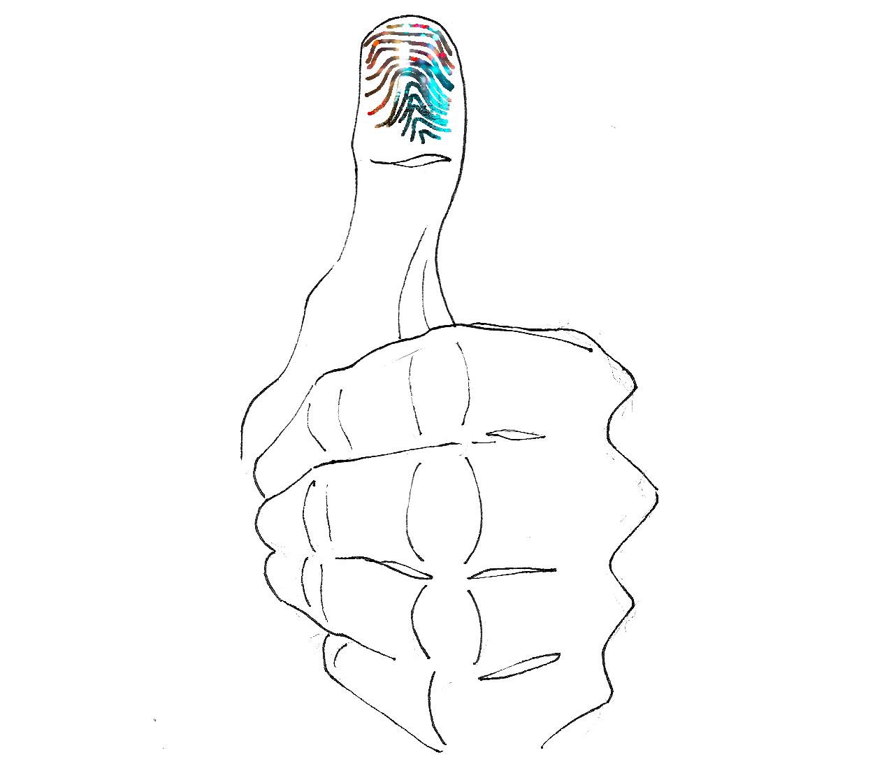
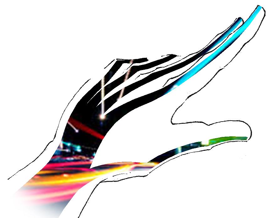
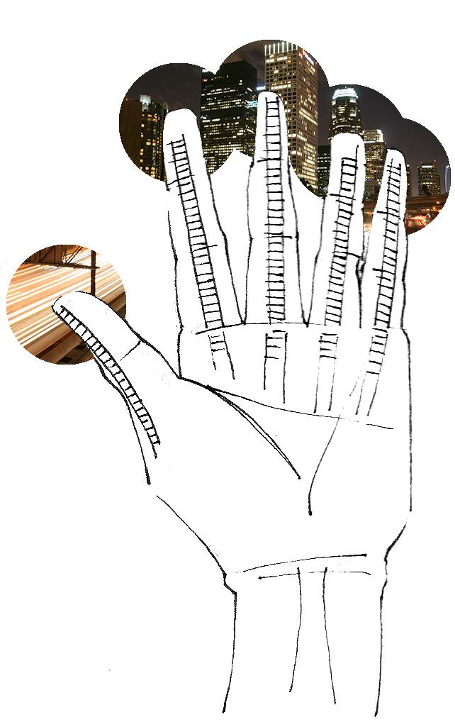
All images show sketches made until 13/02/2015.
54
3. Research about the political and sociological aspects of space and touch. Zygmunt Bauman’s non-space in which we live today that are free from people. We are used to live in a world overpopulated, but we lost the capacity to interact in it. Deal with the huge amount of communication devices that we have today. Improve human contact. One of the objects should be beautiful and attractive to others. Somehow should gave pleasure to the user and to
55
56
57

58

59

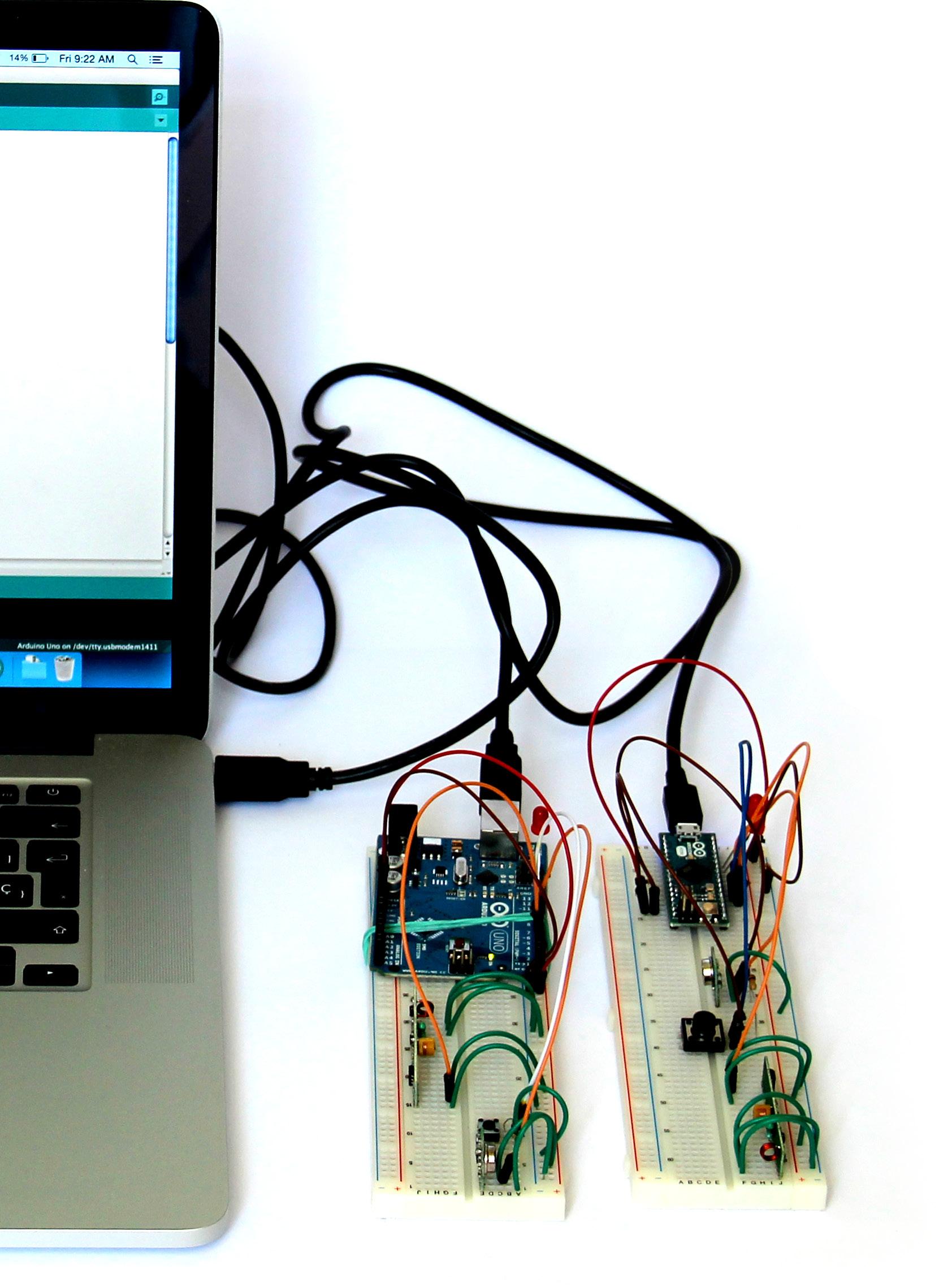
The whole prototype of the electronic and coding part of the project was done with the open-source computer hardware and software ArduinoArduino. is based on a family of microcontroller board designs manufactured primarily by SmartProjects in Italy, using various 8-bit Atmel AVR microcontrollers or 32-bit Atmel ARM processors. These systems provide sets of digital and analog I/O pins that can be interfaced to various expansion boards and other circuits.
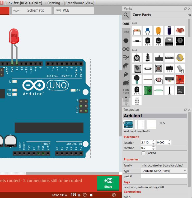
After the eletronic prototype part it was used the software Fritzing, which is an open source software initiative to support designers and ar tists. It was developed at the University of Ap plied Sciences of Potsdam. The main advantage of the software is the easy interface to document and record the layout of the created Arduinoleft: logo. Middle right: Typical screen of Fritzing. ty
The boards feature serial communications interfaces, including USB on some models, for loading programs from personal computers. For programming the microcontrollers, the Arduino platform provides an integrated development environment (IDE) based on the Processing project, which includes support for C and C++ programming languages.
pical tion.FritzingBottominteraction.Right:typicaldocumenta-
60
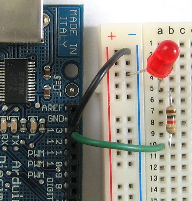
MethodsCodingElectronicbreadboards.andToolsandUsed06|02 Top
Bottom Arduinoleft:and Breadboard
Top ArduinoMiddleFritzingright:logo.left:UNO board.
61


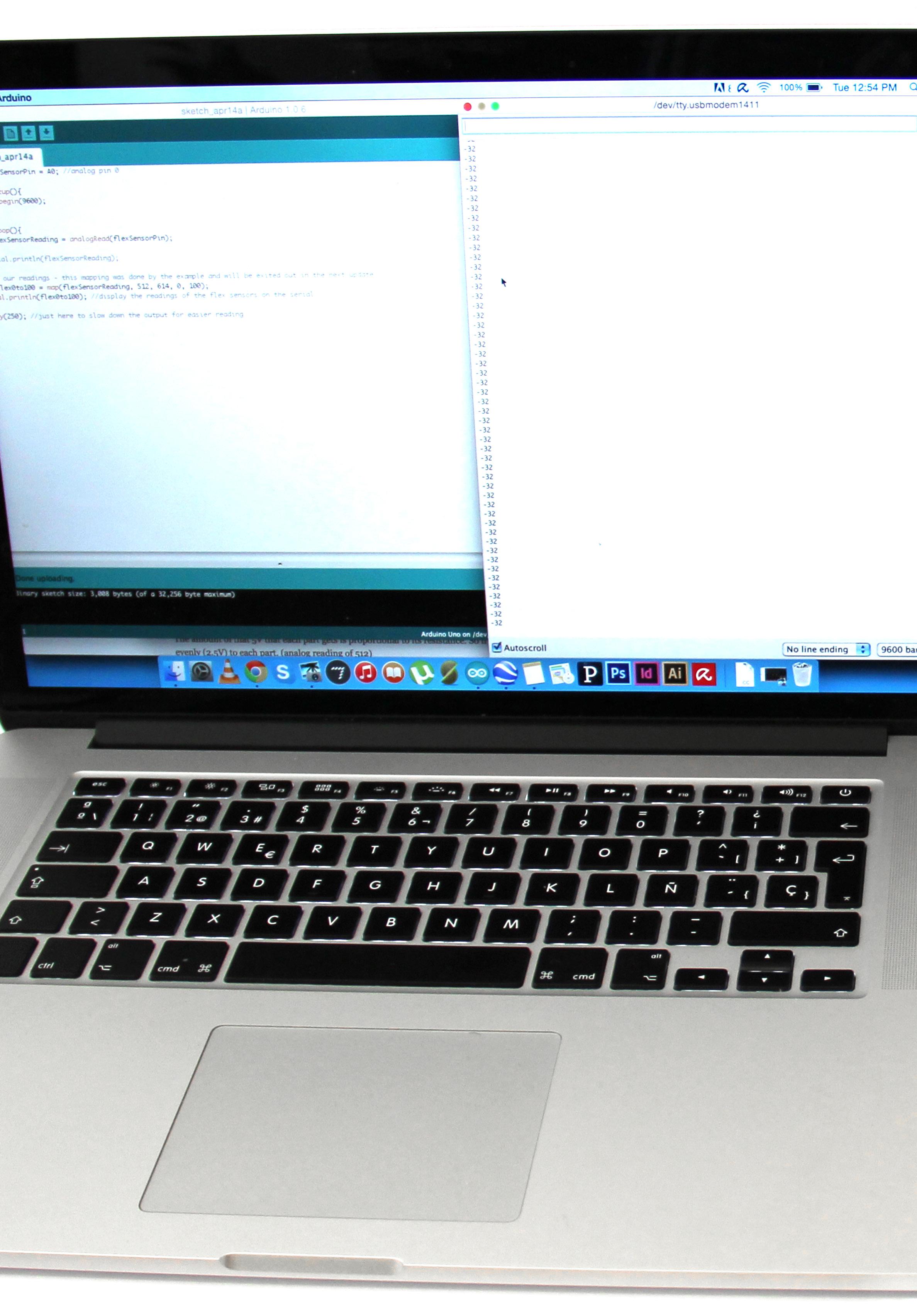
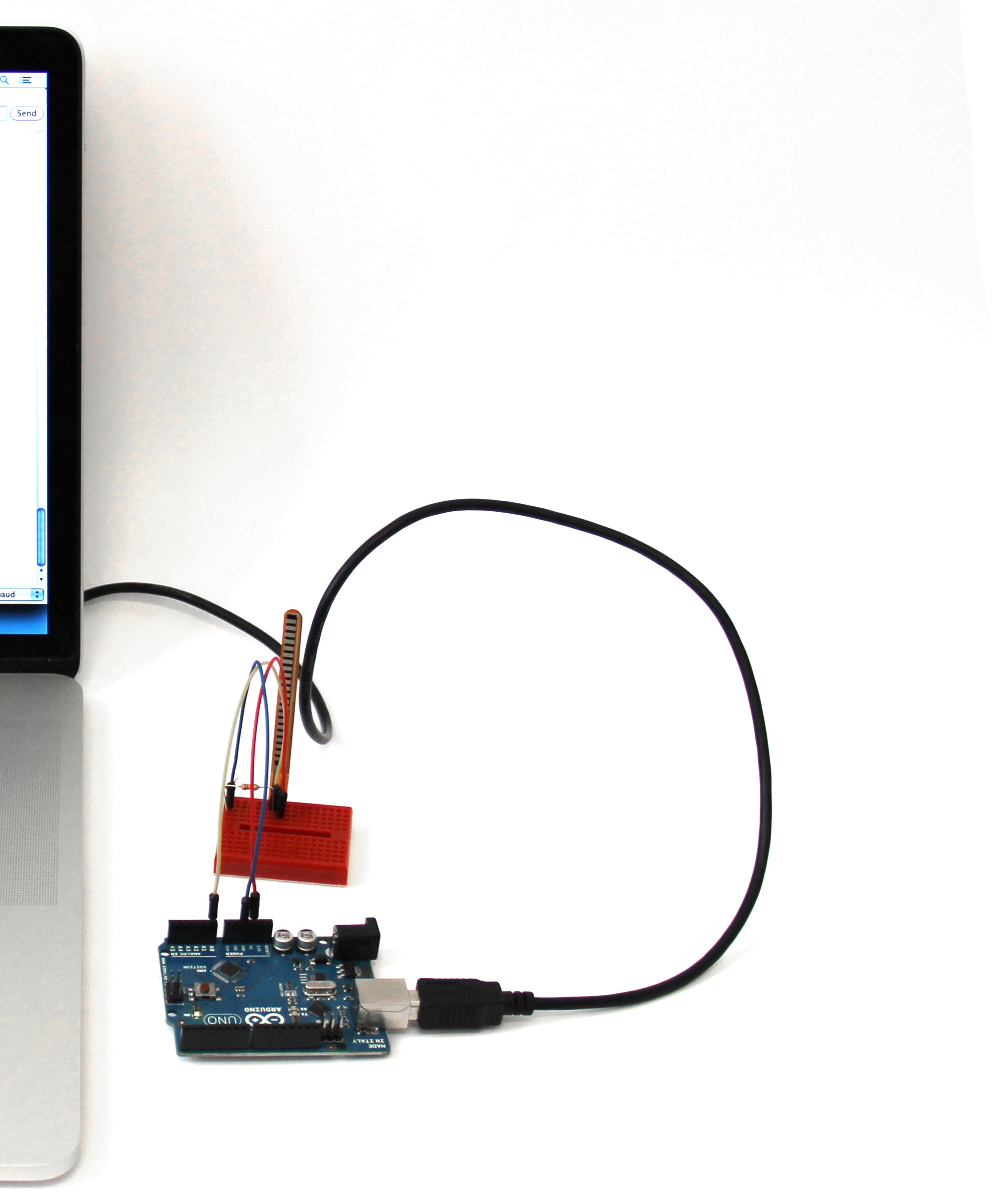
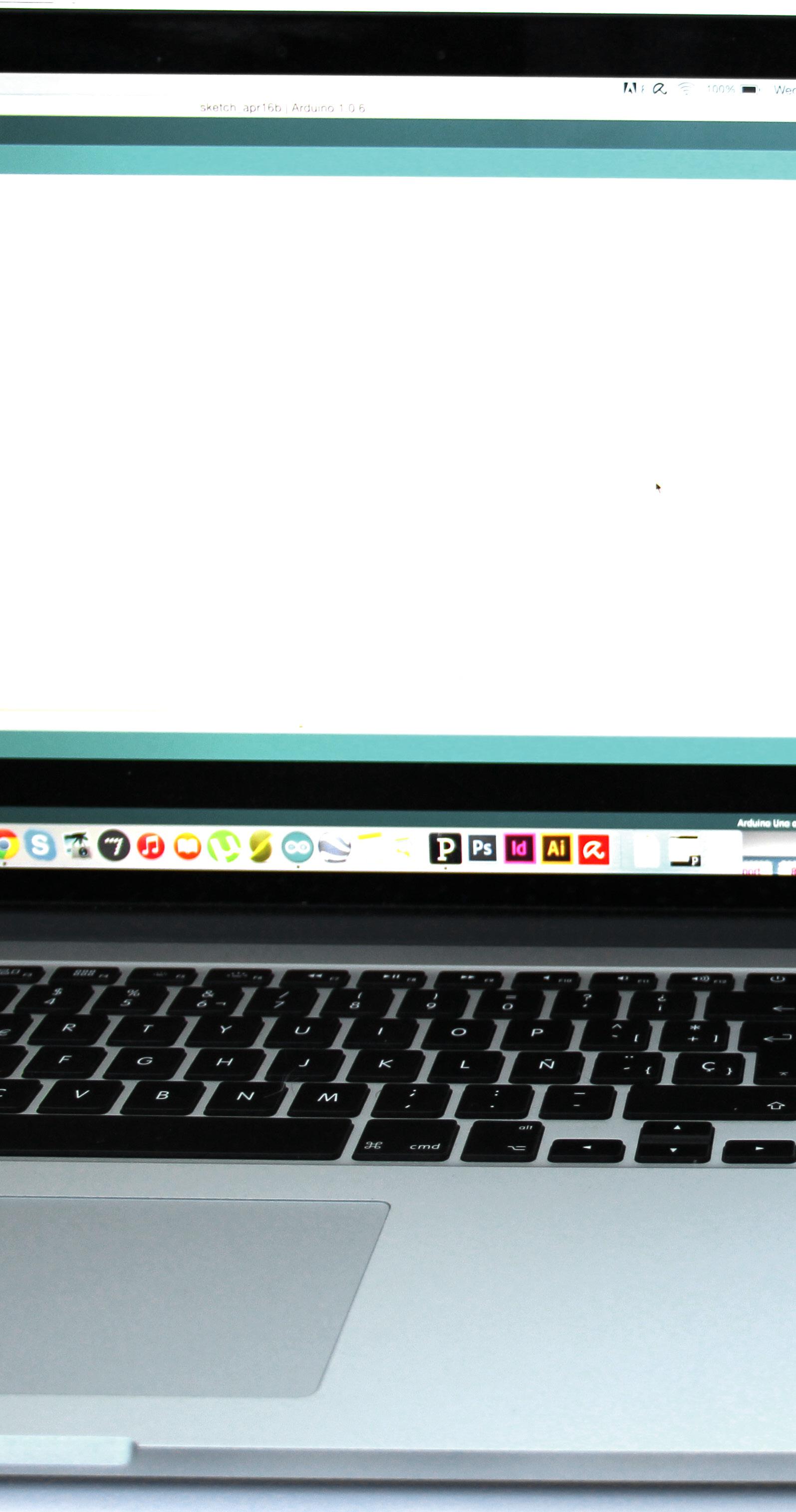
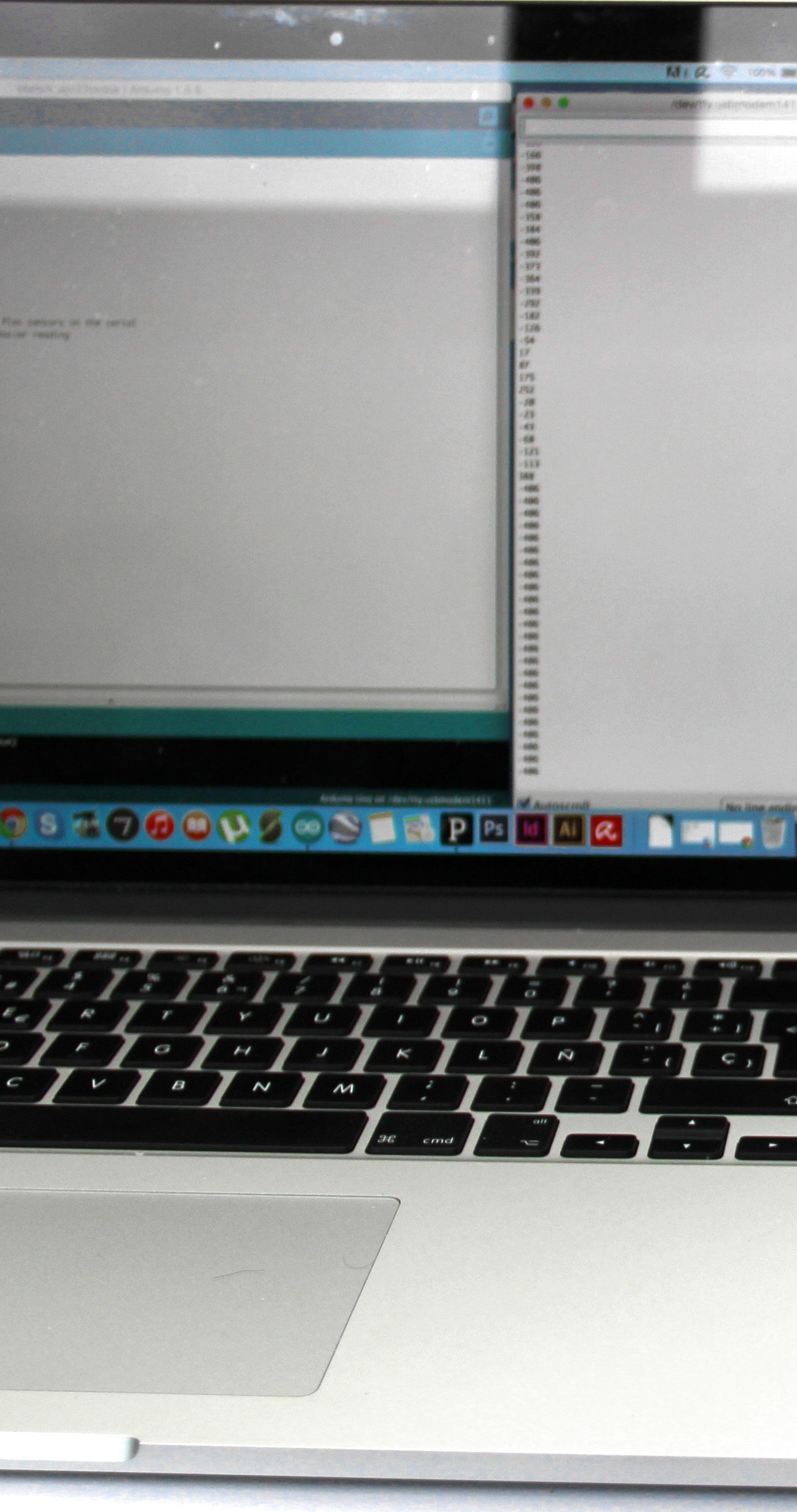
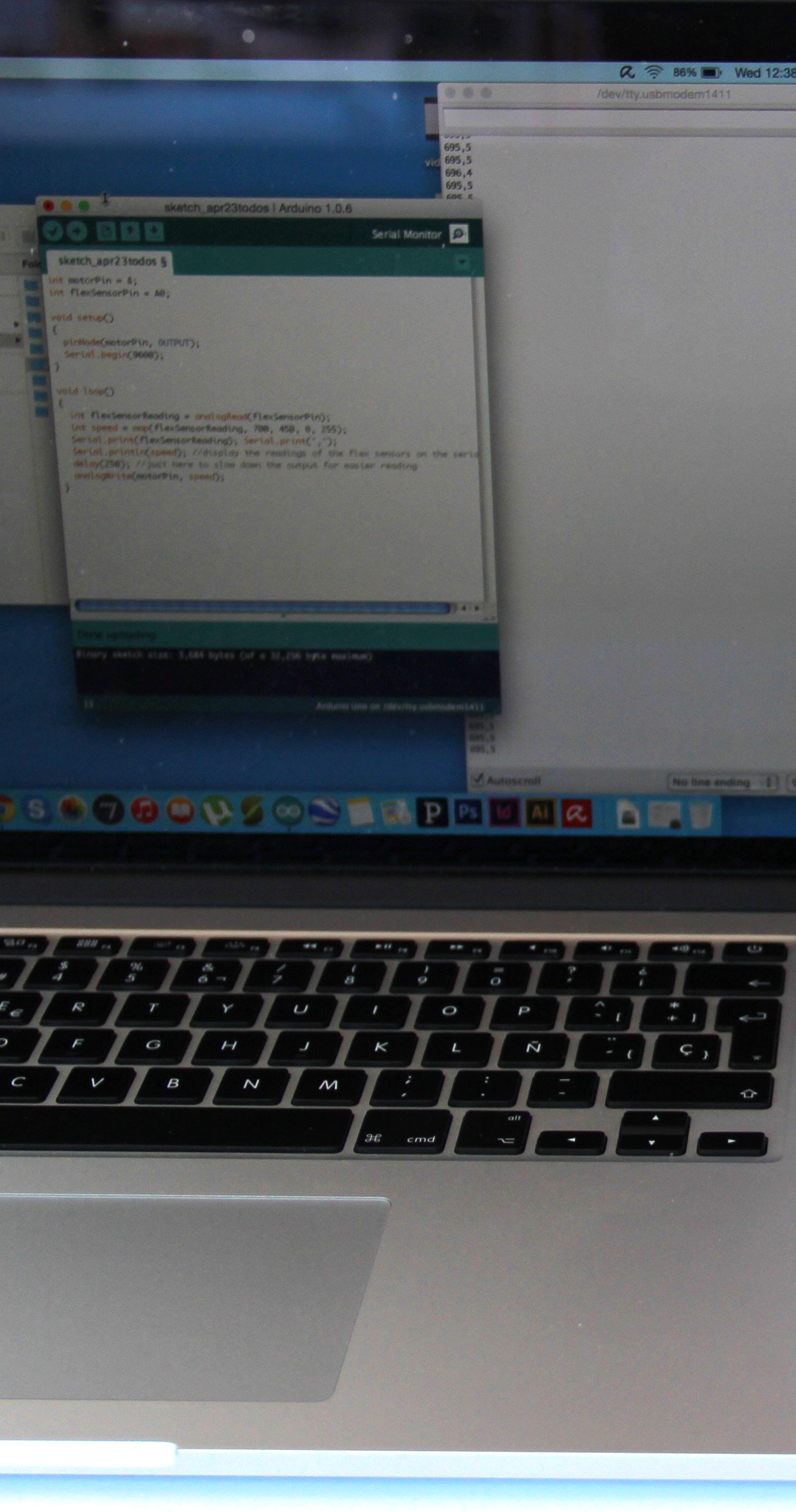
62 Electronic and Coding Evolution06|03 Process - 2015_04_13: First test with one bending sensor and Arduino. The Arduino read the values properly.
63
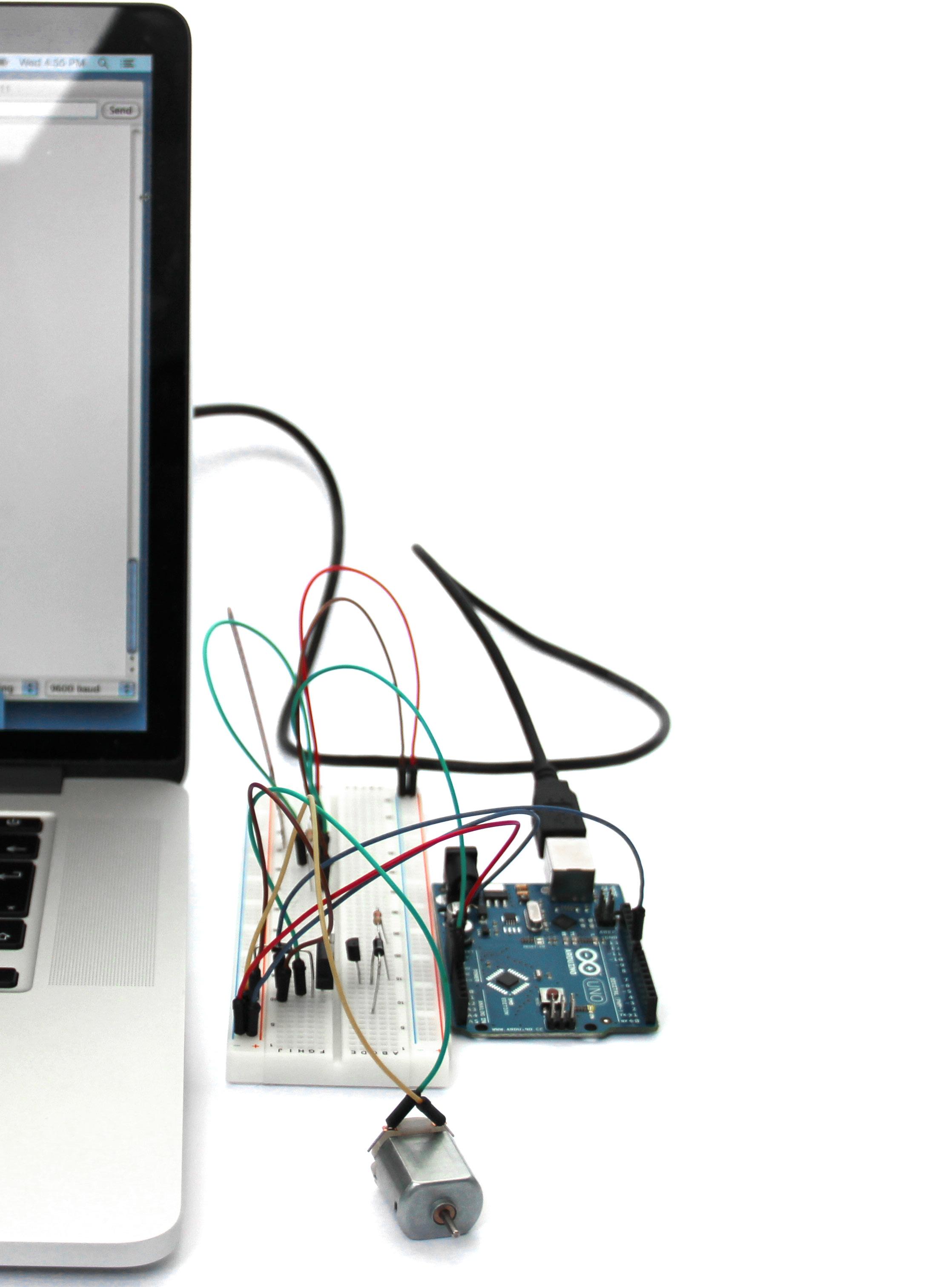
64 Process - 2015_04_16: First test with one bending sensor and a DC motor runing with Arduino. The Arduino was reading the values and and trans lating those values to the speed of the DC motor rotation. The rotation of the DC motor was varying properly, but it was needed an SWIFT component for each pair of bending sensors if this idea continue.
65

The issue is that the arduino is reading extremely diffe rent values, which cause the engine to rotate and stop the rotation.
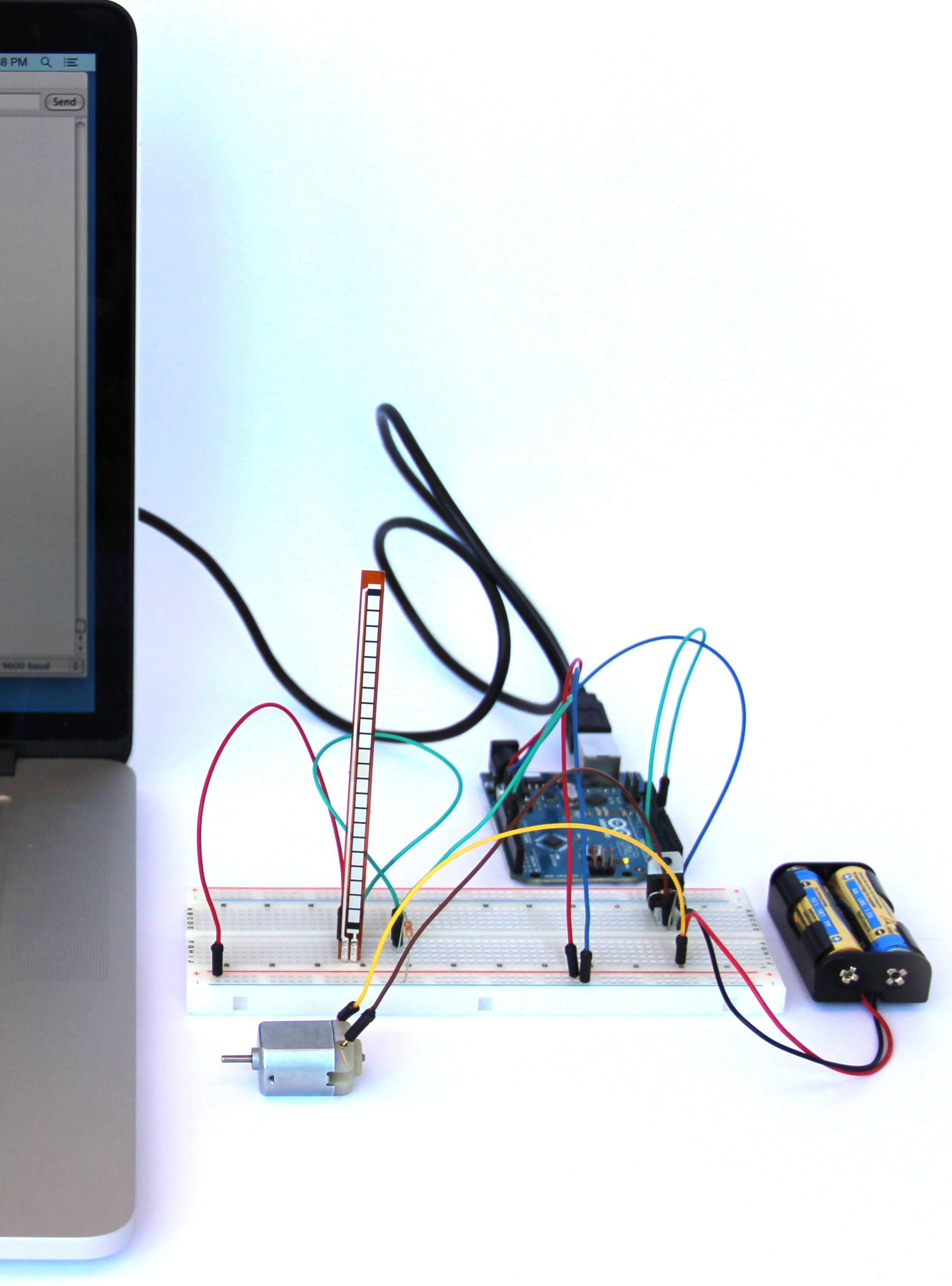
66 Process - 2015_04_23: Second test with one ben ding sensor and a DC motor runing with Arduino. Instead of the SWIFT com ponent, it was used a MOSFET component, together with a resistor, a transistor and a diode, which would be cheaper and could be used together in a group for each sensor.
67
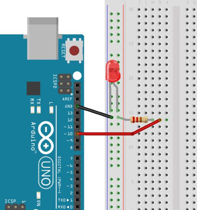
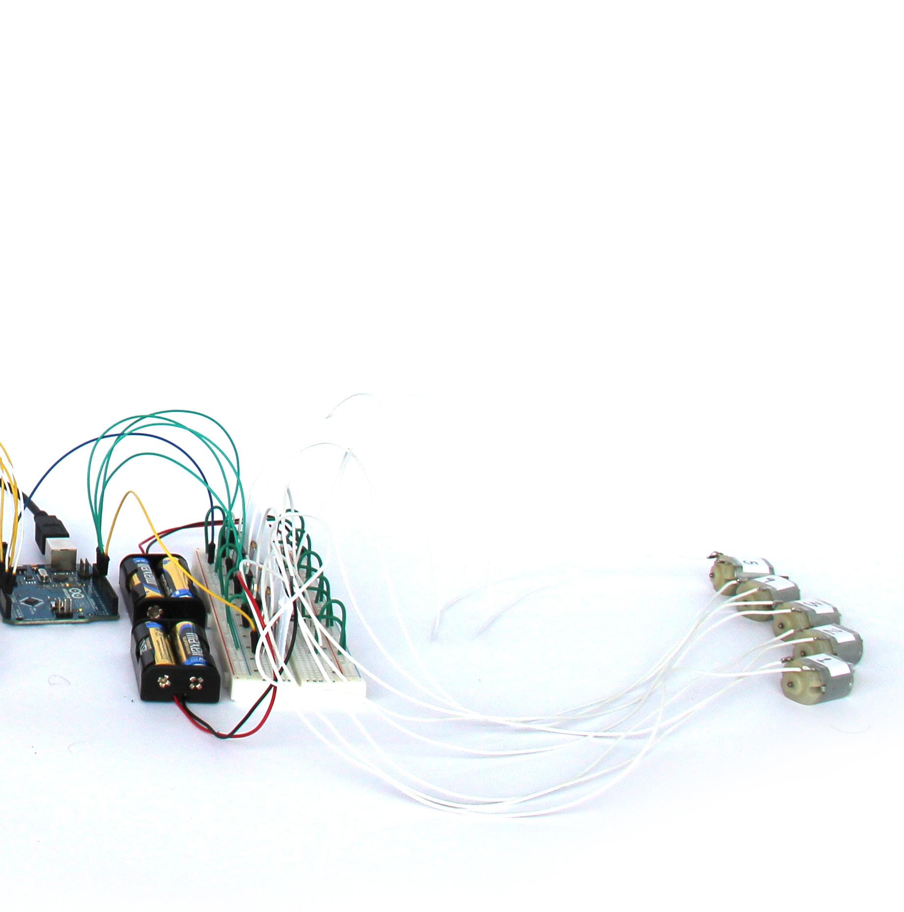
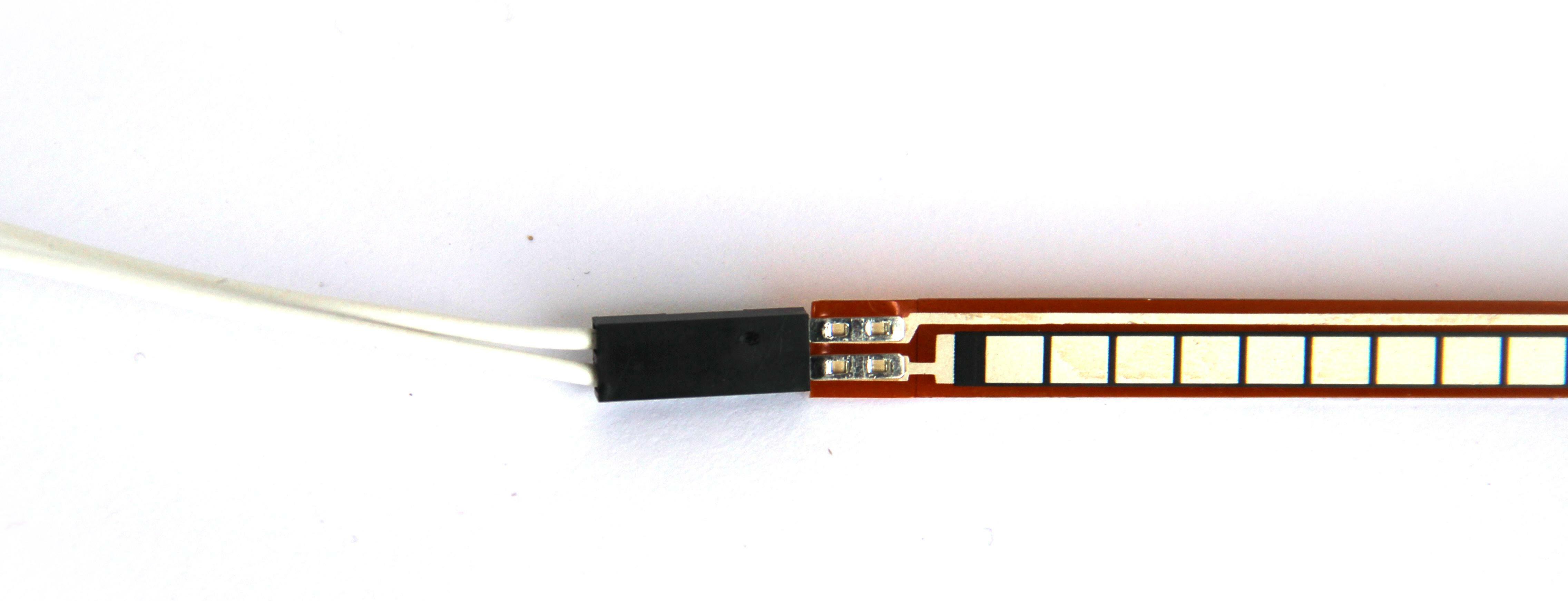
68 Process - 2015_05_05: First test with the final long bending sensor, and DC mo tor running smoothly. This was achieved also with the use of an extra pair of AA Thebatteries.arduino was reading properly the values from the flex sensor. The components were re duced to the minimum possible in order to have the desired effect. The used components are: (for glove part) 1x flex sensor; 1x 22KΩ resistor; (for back part) 1x TIP120 MOSFET; 1x 10KΩ resistor; 1x 4004 diode; 1x pair of AA batery; 1x 3V DC motor; (for everything) 1x Arduino; 1x Protoboard; and jumpers.
69
70 Process - 2015_05_05: Diagram of the Arduino and Breadboard configuration.


71


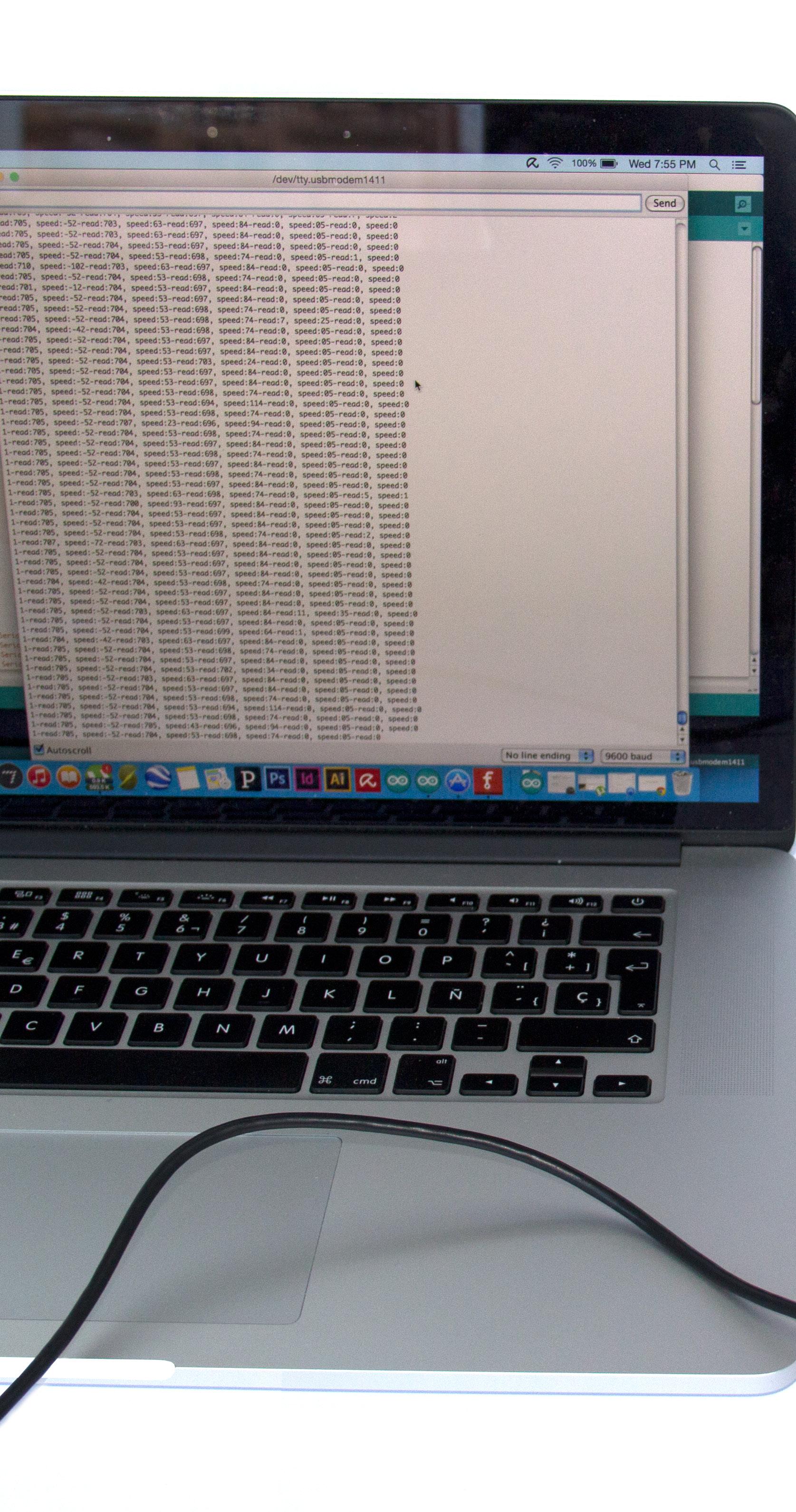
72 Process - 2015_05_06: After the test with one flex sensor and one DC Motor worked properly, it was repeated the same, but for five sensors and five DC Mo tors. For the first time the pres sure sensor was used and worked properly. The major change were on the script part and calibra ting all of them. The extra power suply wor ked, but an issued appeared. The extra power suply wasn’t enough for the five motors, so the last motor to receive the charge was run ning slower htan the first one.
73
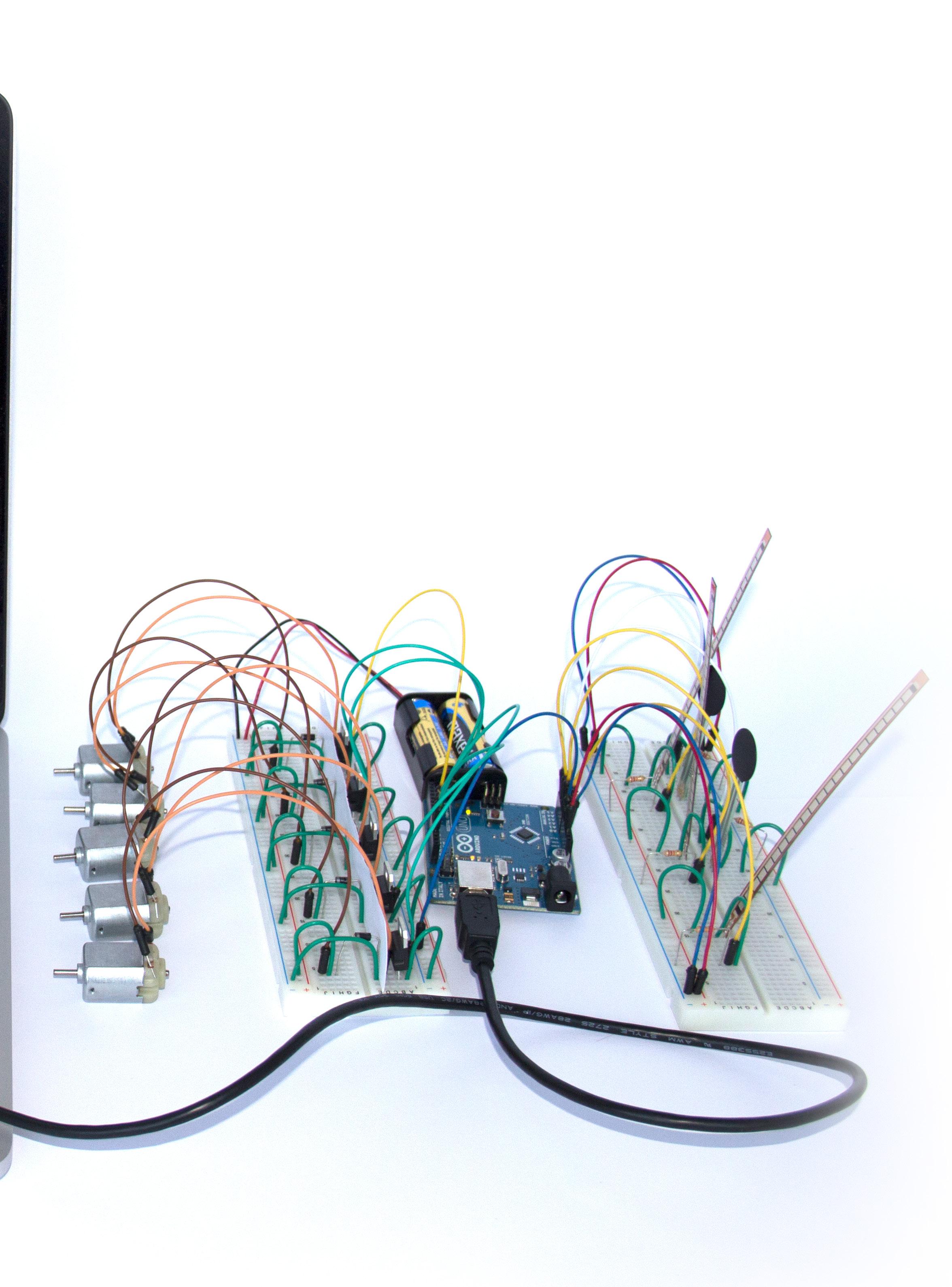
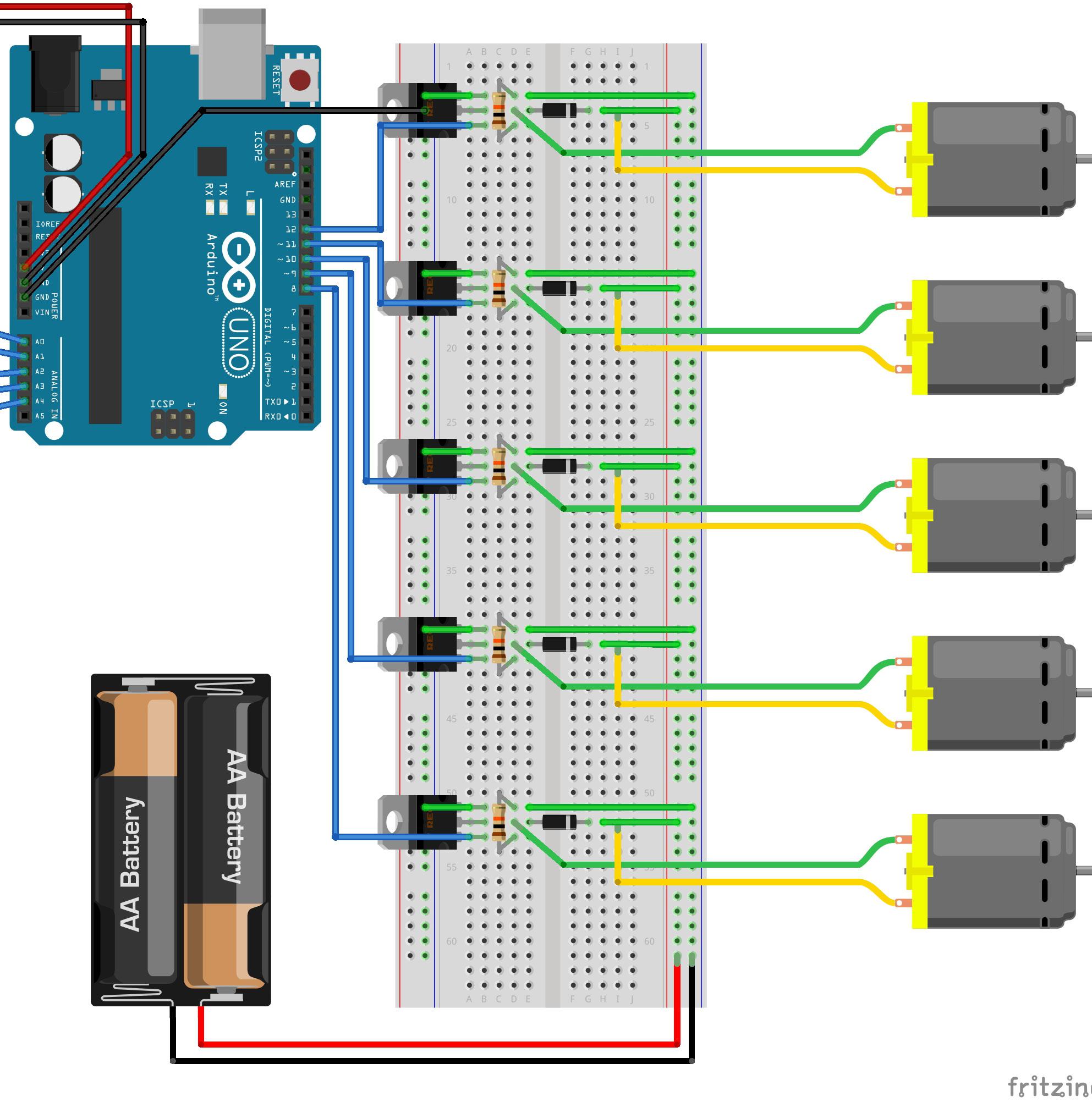
74 Process - 2015_05_06: Diagram of the Arduino and Breadboard configuration.

75
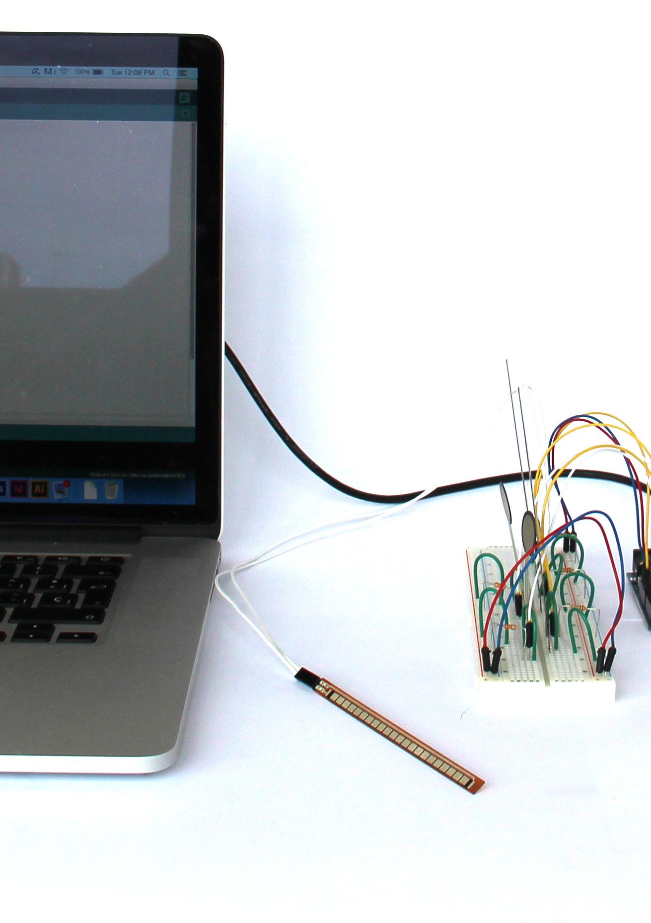
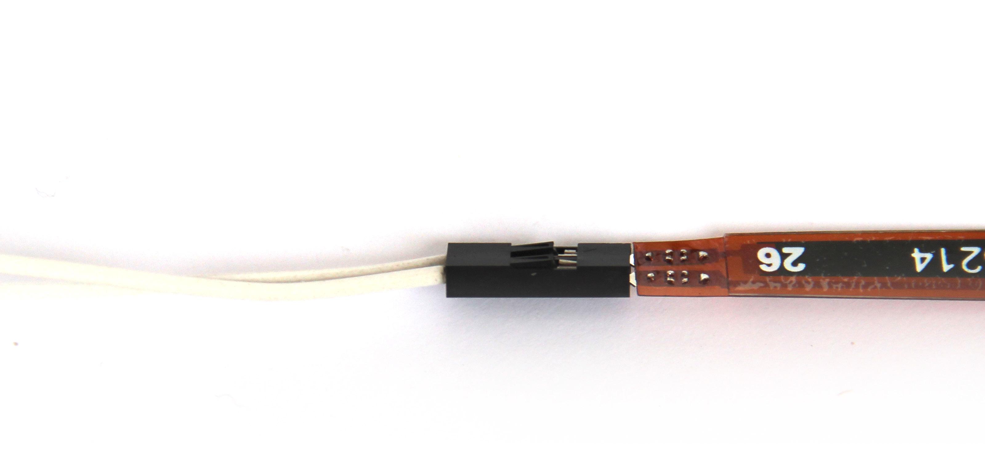
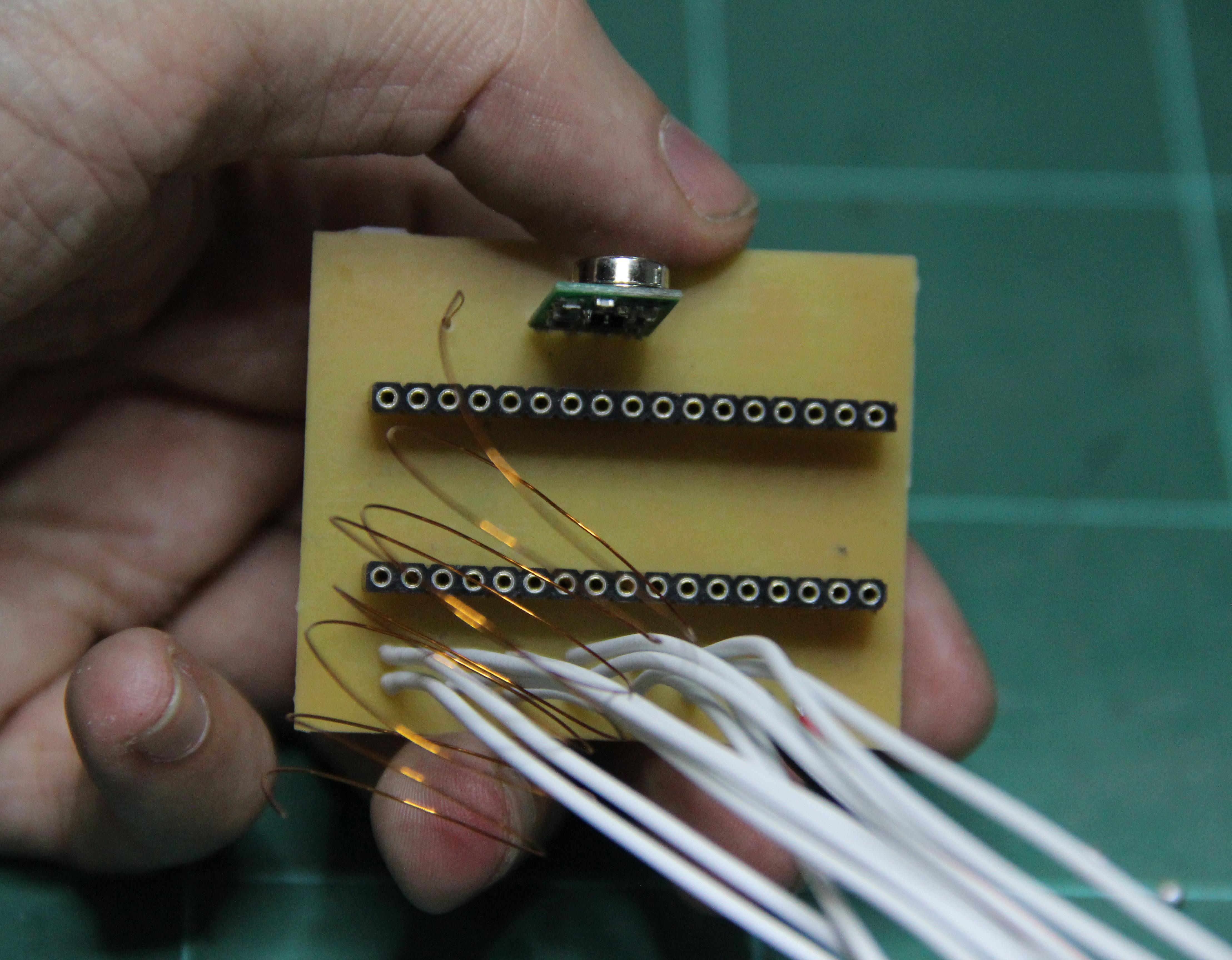
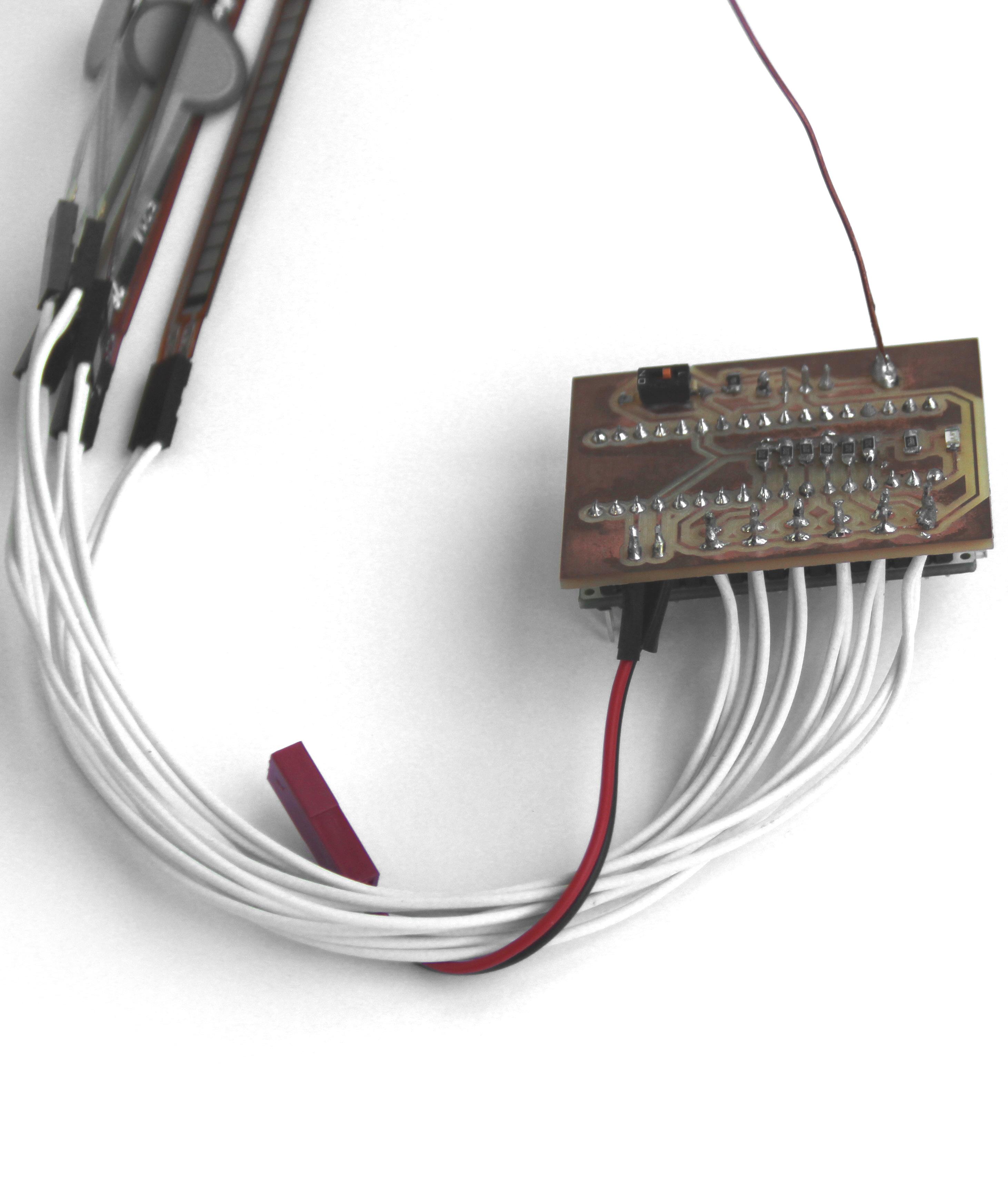
76 Process - 2015_05_15. The breadboard configura tion and the arduino script were manteined, the only difference is that the wires started to be produced. Jacks of two pins were used together with white wire, in order to be ease to be re moved if necessary and to do not appear very much on the user.
77
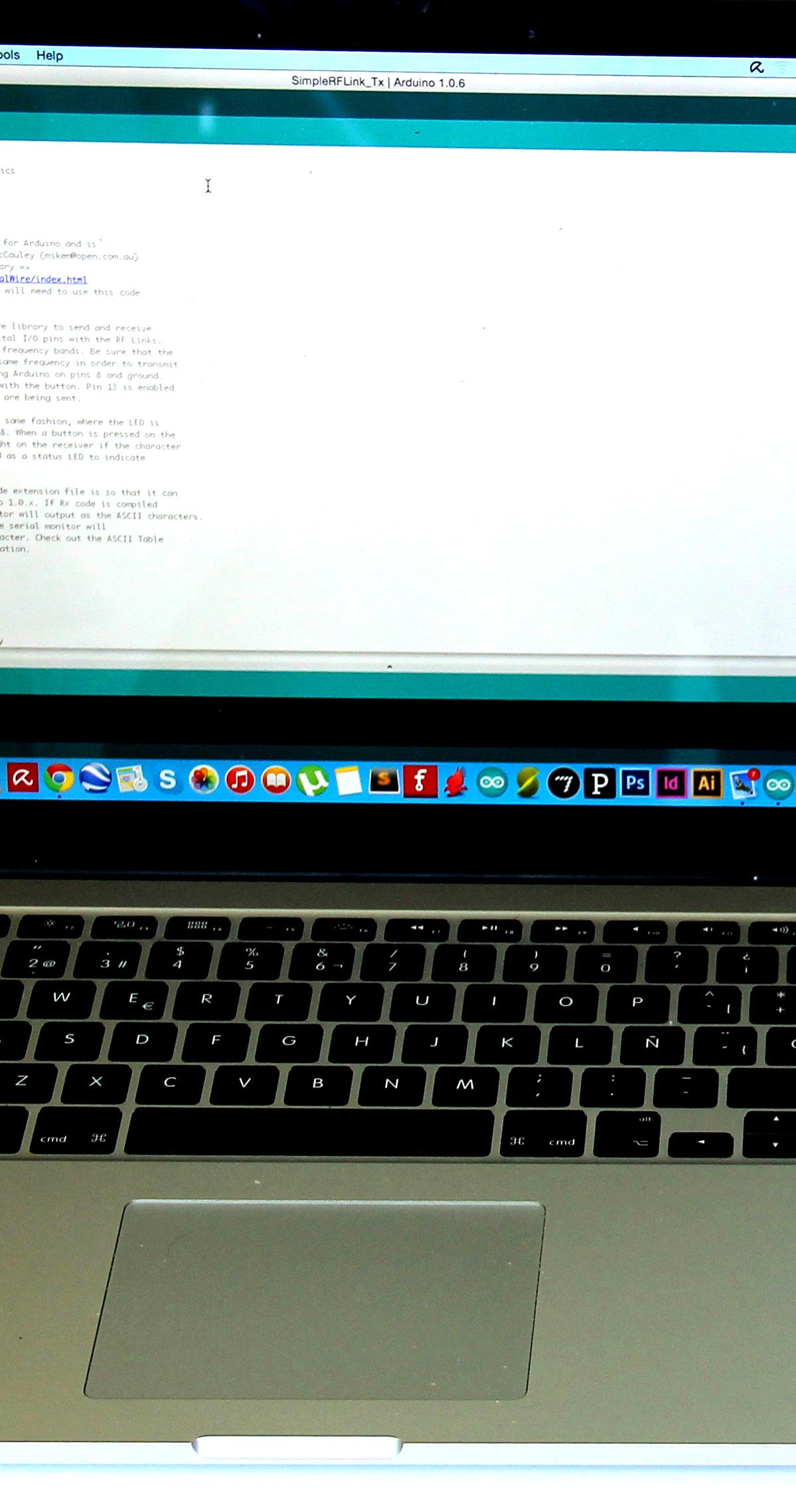
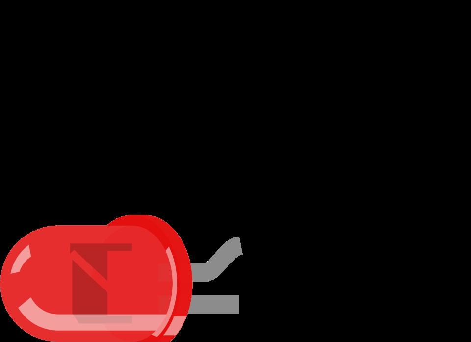
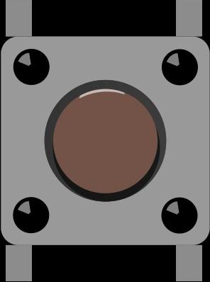
78 Process - 2015_05_21: The first test with the radio frequency receivers and transmitters were made and sucessfull one integer as data from one arduino was send and received by the second one lighting an LED, and vise versa. The components used were: (for the transmitter parts) 1x RF Link Transmitter (315MHz); 1x RF Link Transmitter 2x2x(434MHz);Pushbutton;10kΩresistors; (for the receiver parts) 1x RF Link Receiver4800bps (315MHz); 1x RF Link Receiver4800bps (434MHz); (for both) 1x Arduino UNO, 1x Ardui no Micro, Jumpers, Breadboards, and LED’s.
79
80 Process - 2015_05_21: Diagram of the Arduino and Breadboard configuration.


81


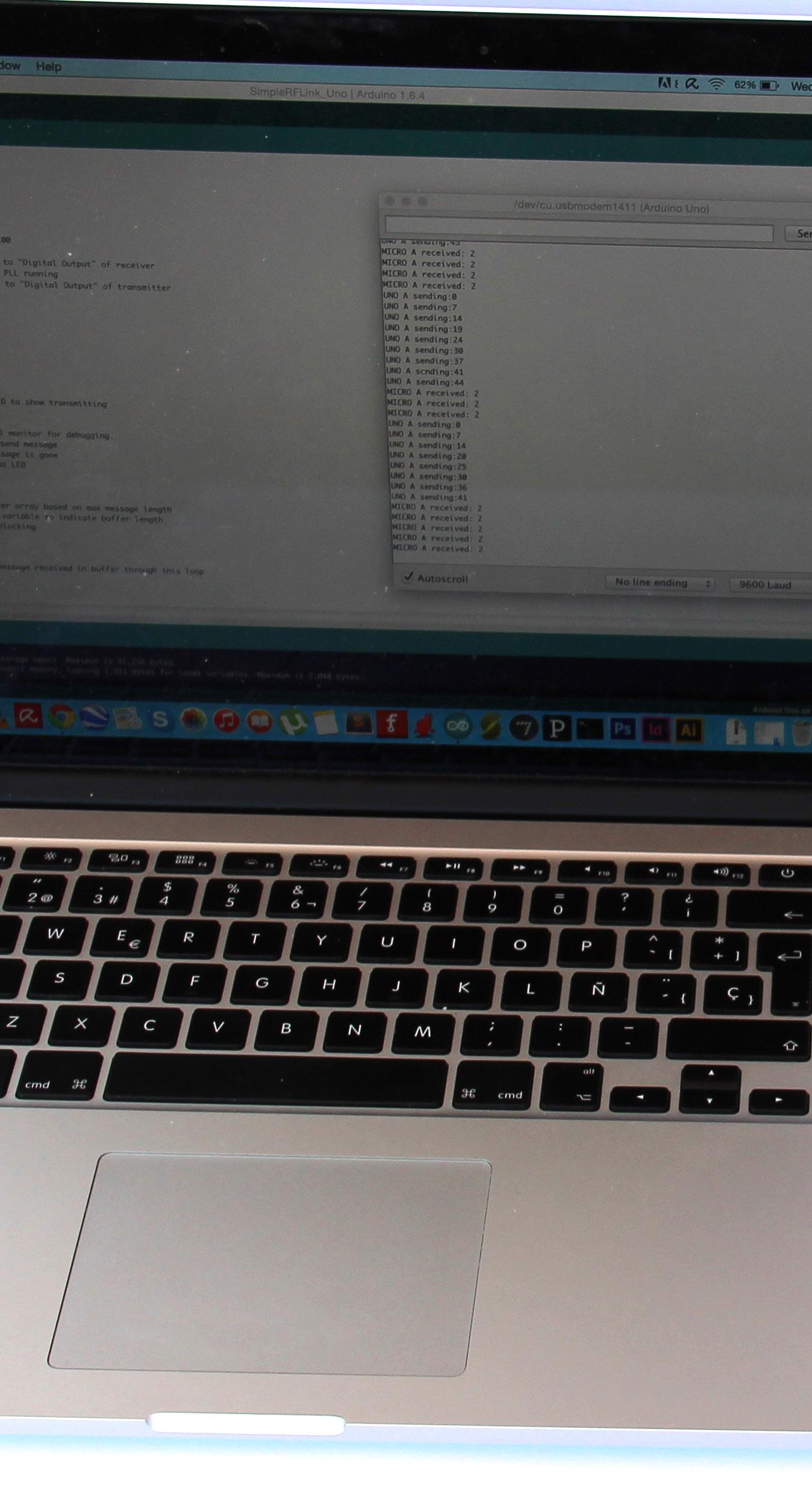
82 Process - 2015_05_27: The second test with the ra dio frequency receivers and transmitters were made and sucessfull not only one inte ger, but a String of integers were send and received from one arduino was send and received by the second one lighting an LED, and vise versa. The String was generated by one potentiometer in each board and the result is displayed in the Serial Mo nitor.
83
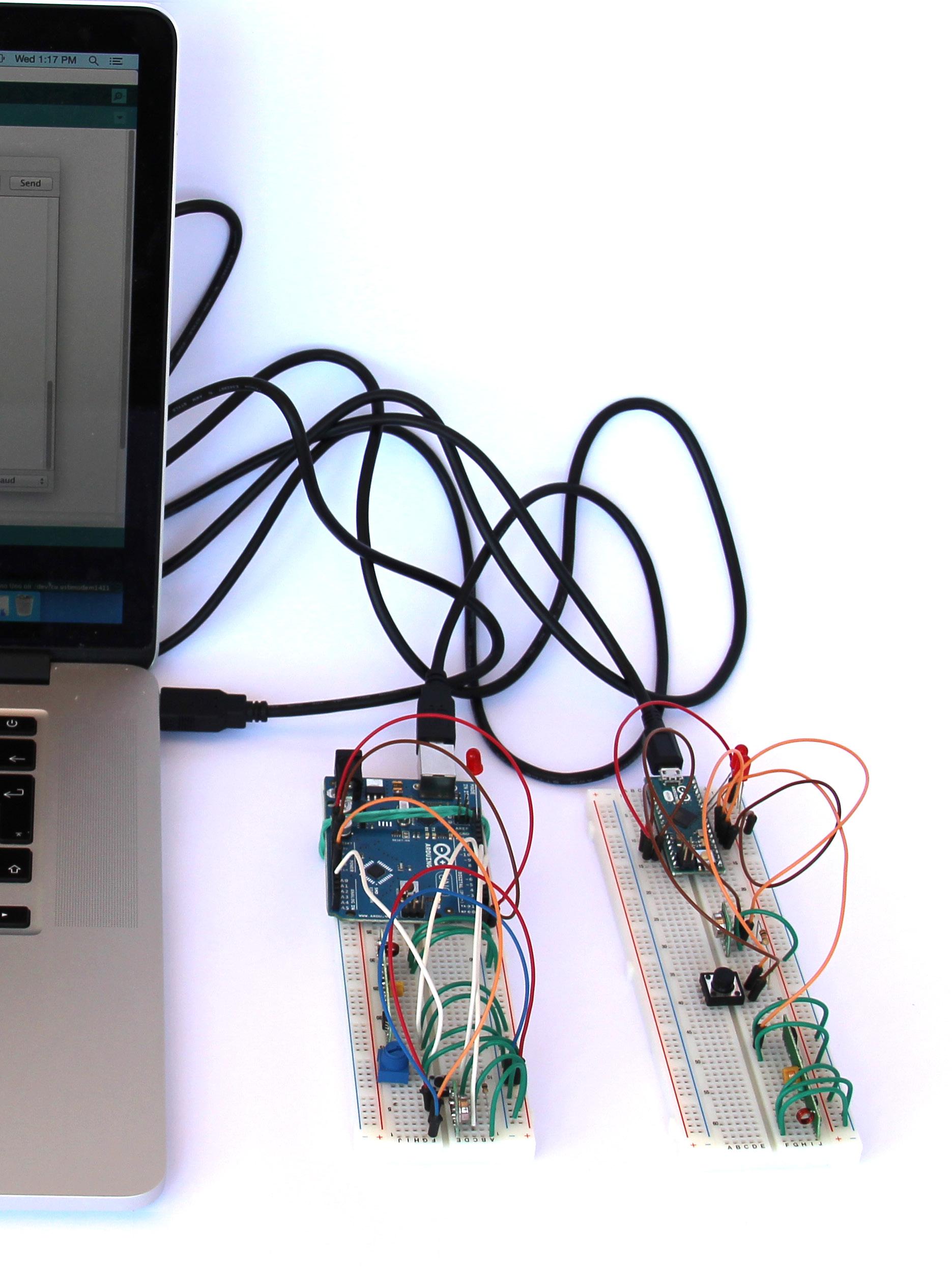
84
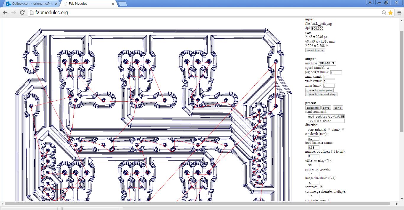
The software used for this was the Fabmodules.
-
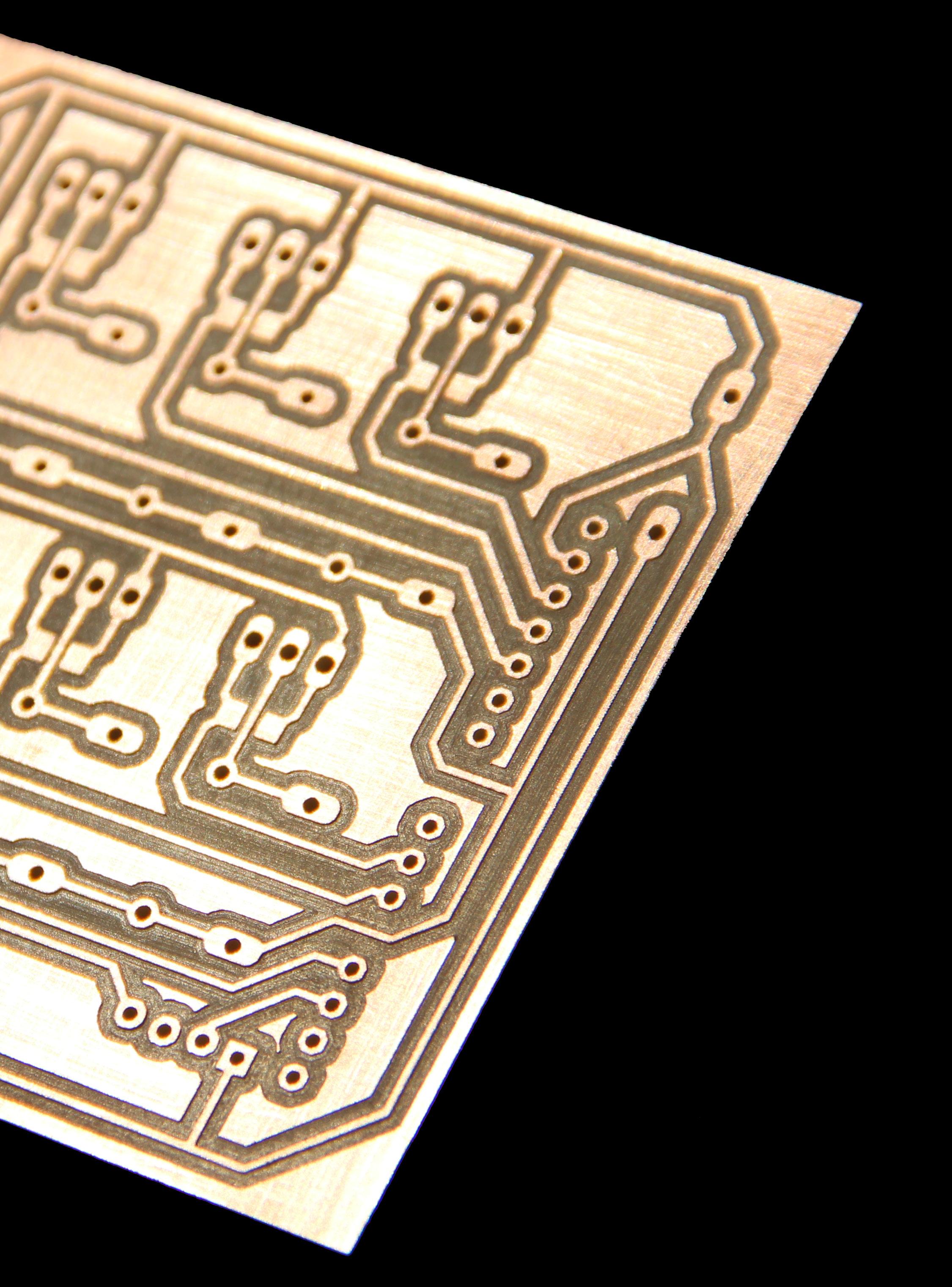
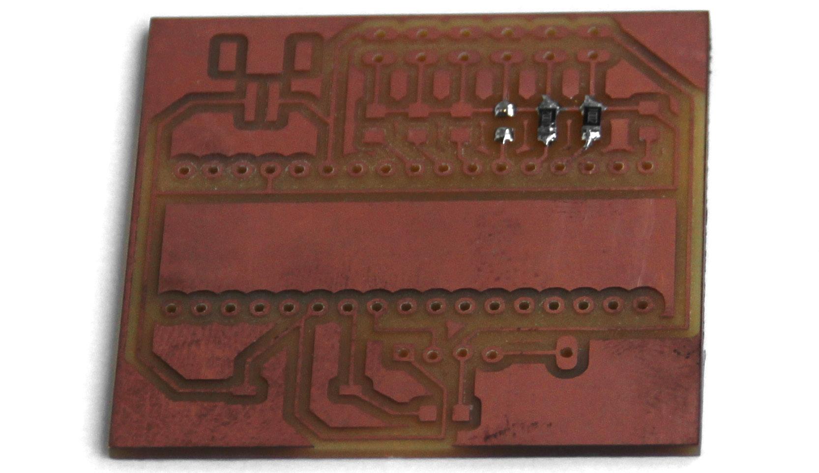
Circuit Board Project and Method of Fabrication06|04
Top CADleft:Soft EAGLE logo.
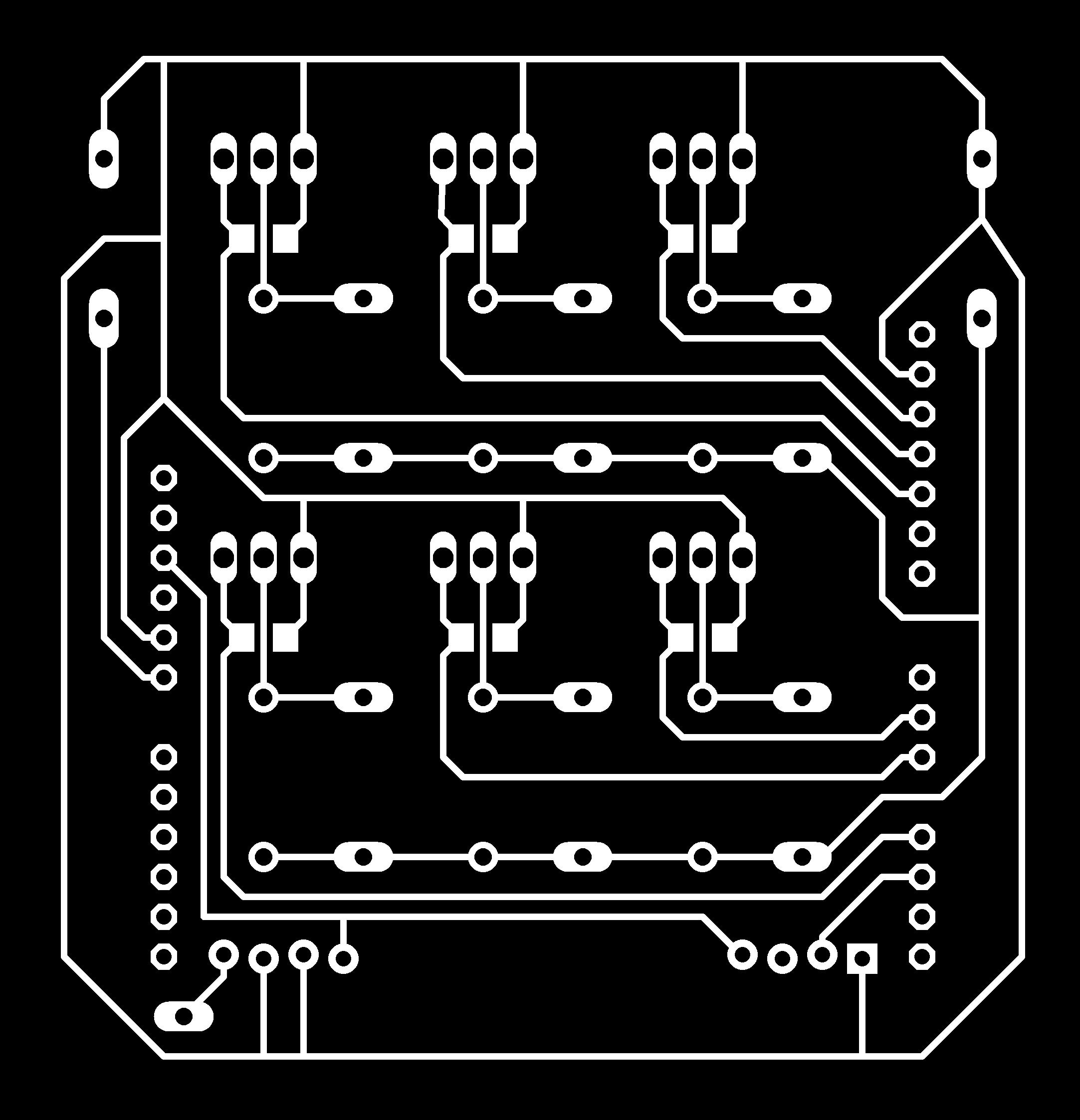
Top Eletronicright: eschematic of one of the circuit board drilled (the Arduino UNO one).
Middle left: Board layout of the same circuit MonocromeMiddleboard.right:image for printing the board generated by the software EAGLE.
After all the eletronic components were tested and improved at the protoboard, it was necessary to make a final shield for the Arduino in order to decrease the size of the circuit, made it user friendly, and more important, made it Itportable.wasused the software CAD Soft EAGLE for creating the schematic and the board design.
FabmodulesBottom: interface, for generating the CNC code for the CNC Router.
EAGLE (for: Easily Applicable Graphical Layout Editor, German: Einfach anzuwendender grafischer Layout-Editor) by CadSoft Computer is a flexible, expandable and scriptable EDA ap plication with schematic capture editor, PCB layout editor, auto-router and CAM and BOM tools developed by CadSoft Computer GmbH, Germany, since 1988. EAGLE is popular among smaller design houses and in academia for its favourable licensing terms and rich availabili ty of component libraries on the web.[citation needed] Hobbyists are attracted by the availa bility of freeware licenses. After the board was designed with the most efi cient use of the small space available, the CNC code was generated. Due to try and error pro cess, a more fast speed configuration was used, making only five offset paths of cut in each line.
85

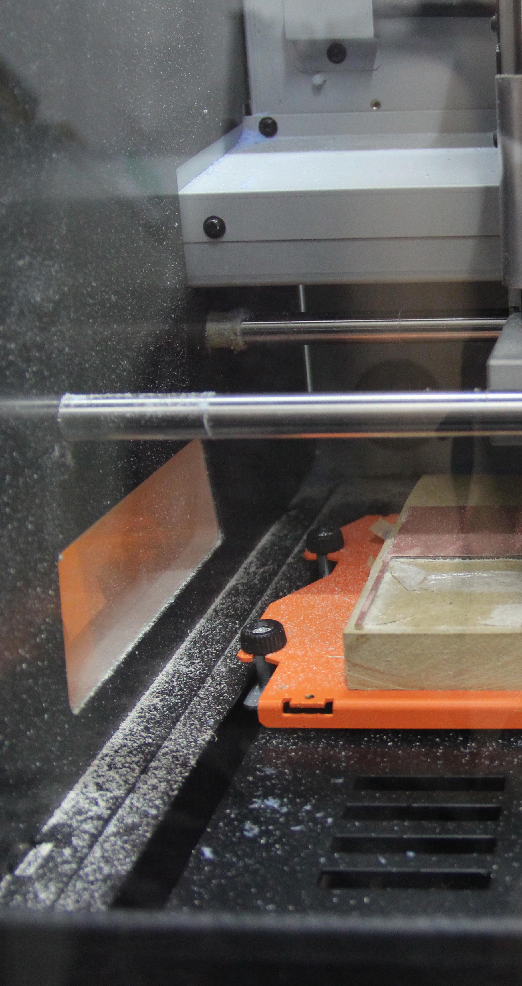
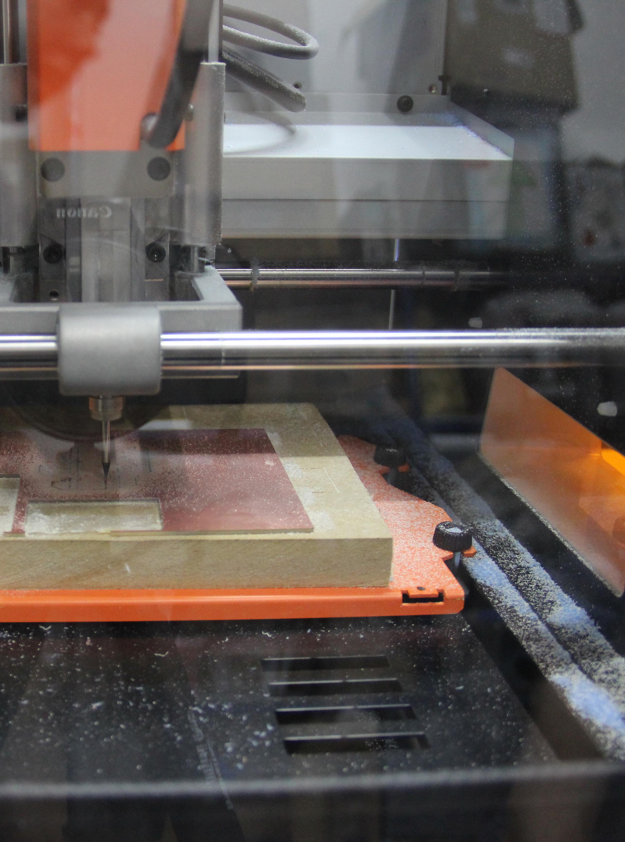
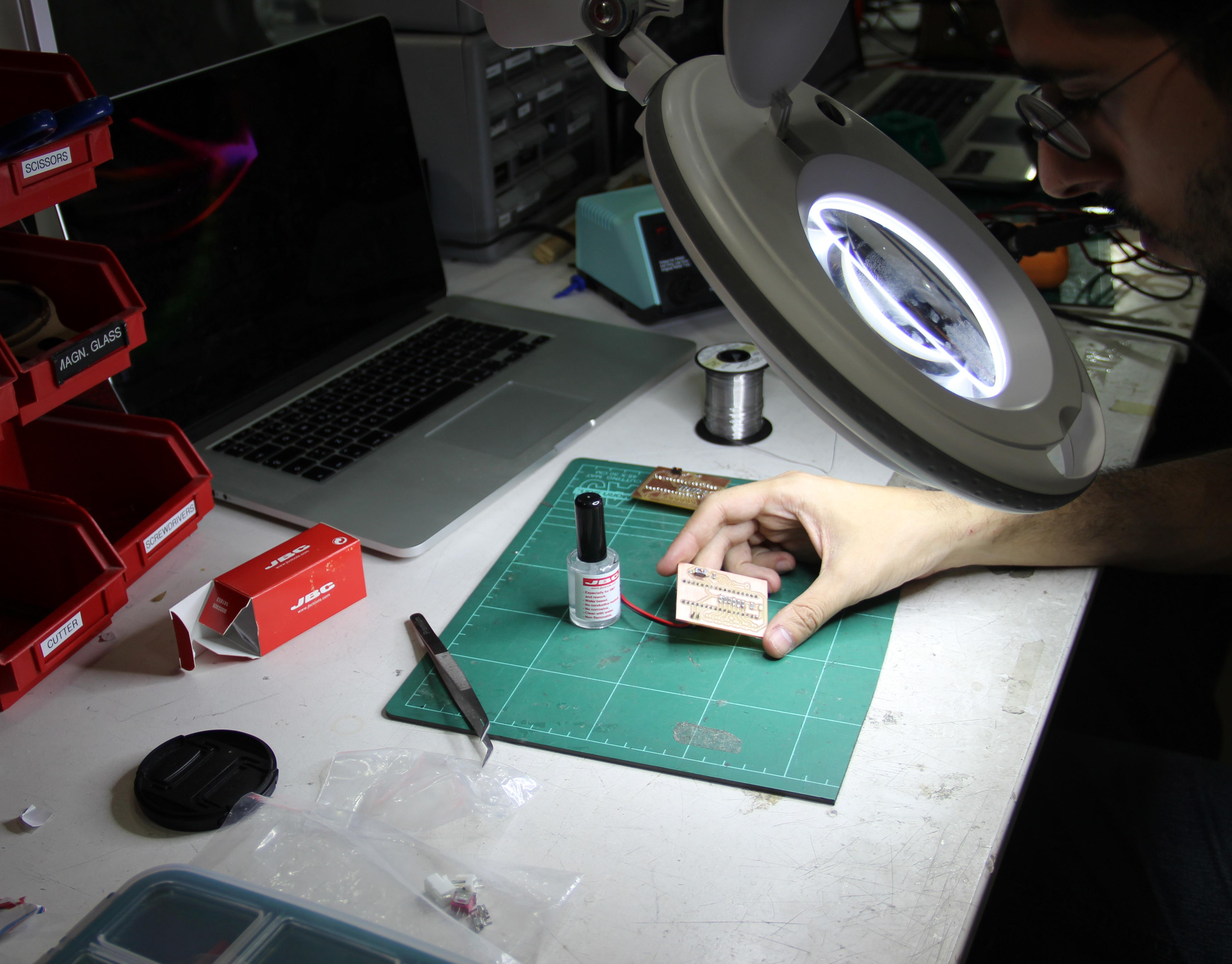
86 For milling the circuit boards (Arduino Shields), it was used a Holland Mill, with a 1/64 and 1/32 drill. The average of time on each board was two to three hours.
87
88 After the milling process, it is necessary to clean the Firstboard.the little copper grains that are generated during the milling process are re moved carefully with the use of a steel sponge. Then the circuit board is cleaned with acetone for removing the tape, alcohol and water. It is cleaned with a paper towel and the result is show in the picture.

89
90

91
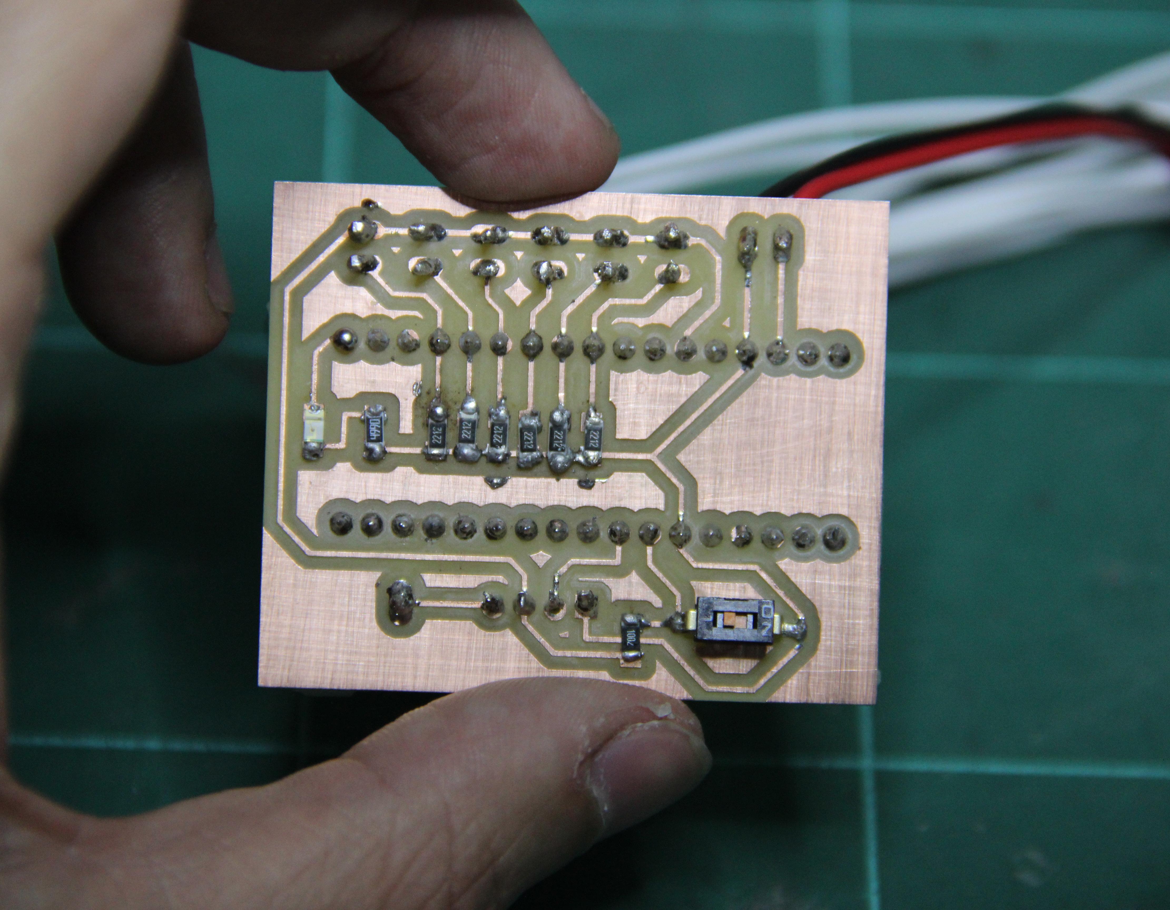
4. The final board, with all the correct components at the right location.
To achieve the desired le vel of qualit at the Arduino Shield (circuit board), the steps were:
2.3.1.
1. Milling the first good qua lity board, which unfortu nately, the desired electric plug wasn‘t available at the local electronic store, and needed to be change;
92 Circuit EvolutionBoard06|05
2. At this board, it was veri fied that the resistors were connected in series at the wrong side of the polarity of the circuit;
3. At this board, it was in dentified that the external batery positive input was connected to the wrong pin of the arduino, which would cause a short-circuit.

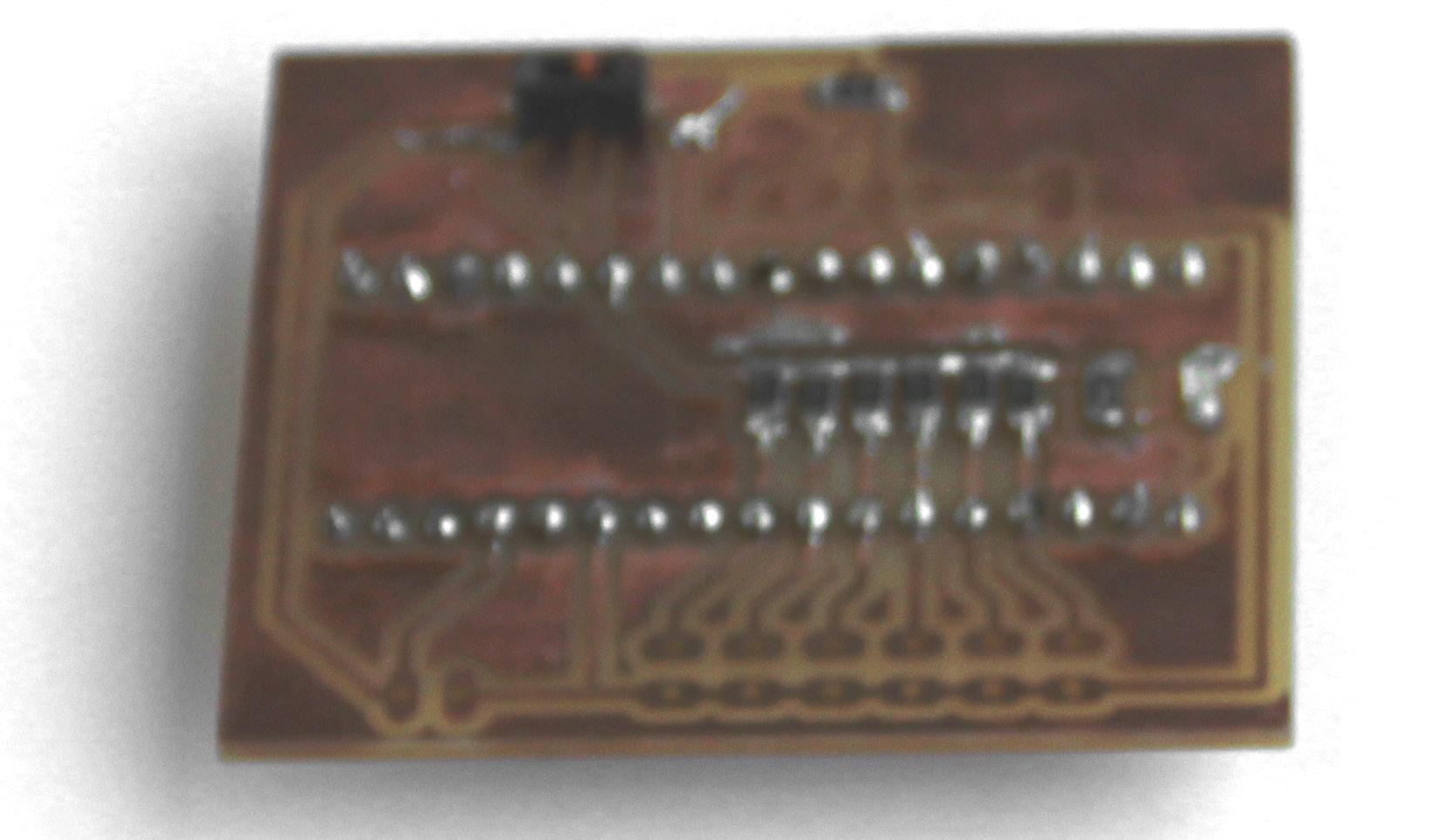
93 4.
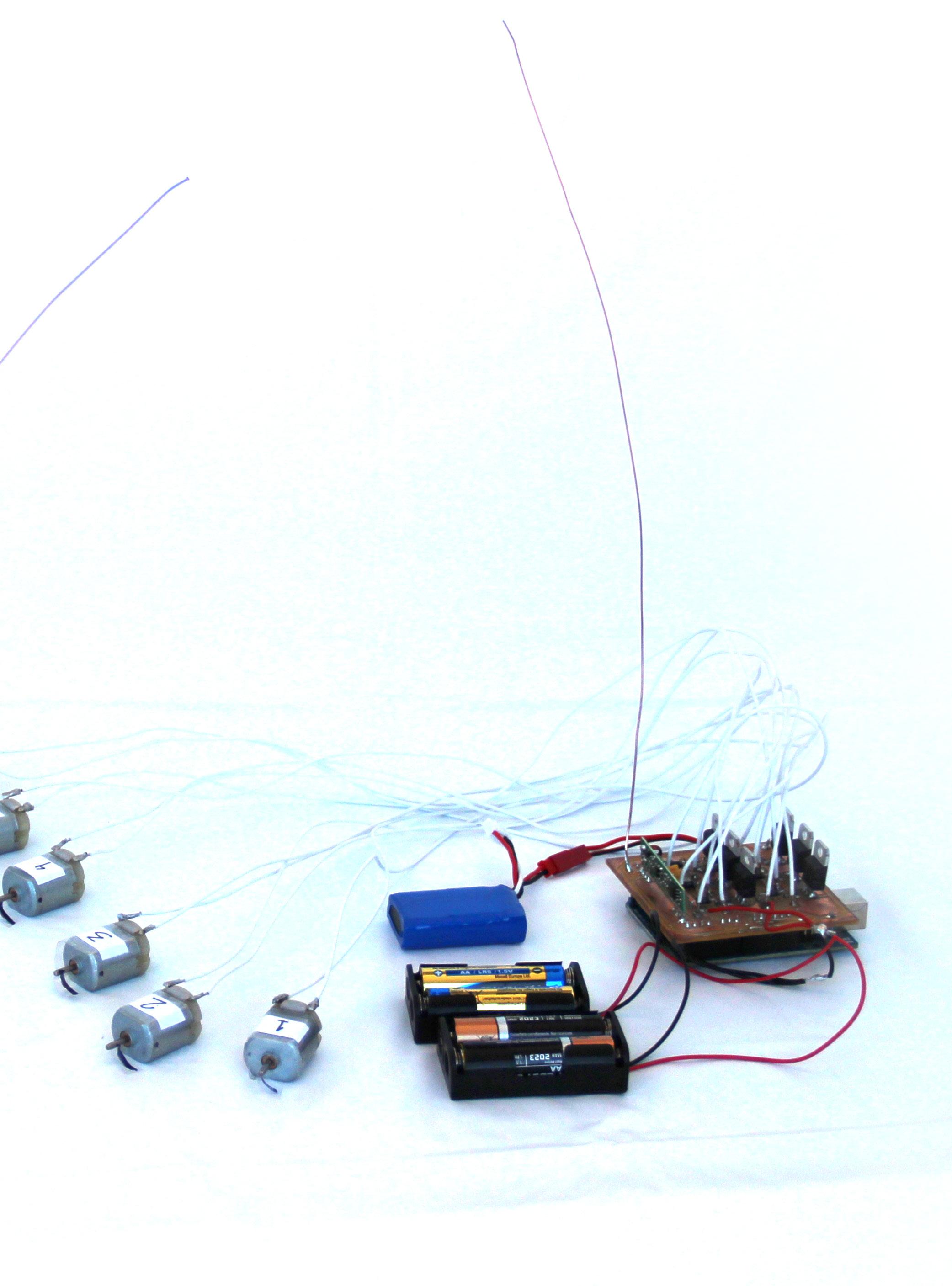
94 All the Arduinos, fabricated shiels, sensors, motors and batteries working properly.

95
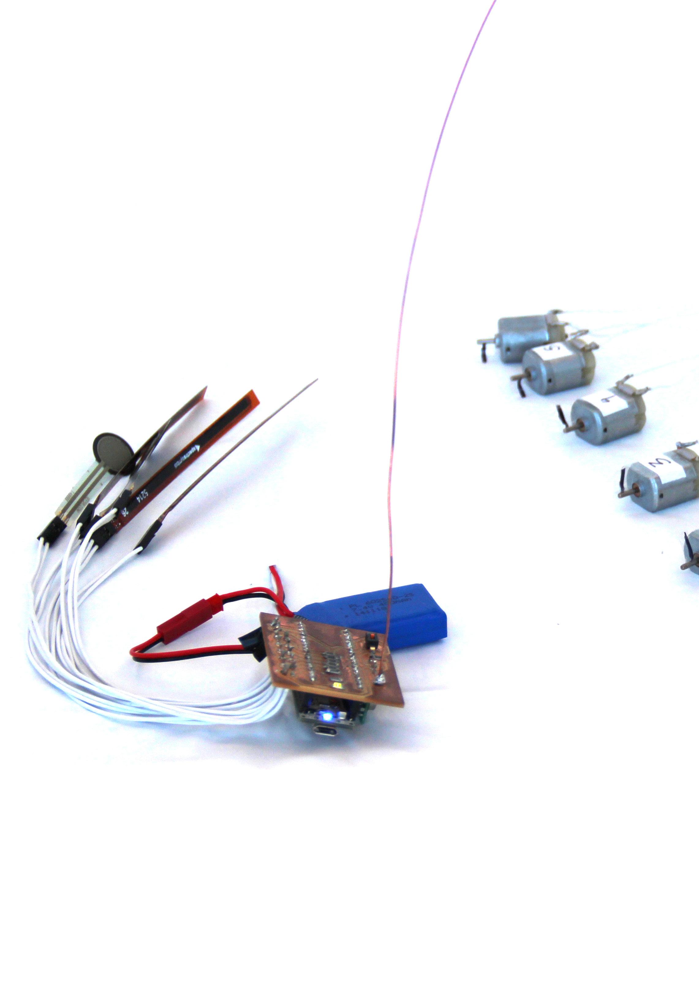
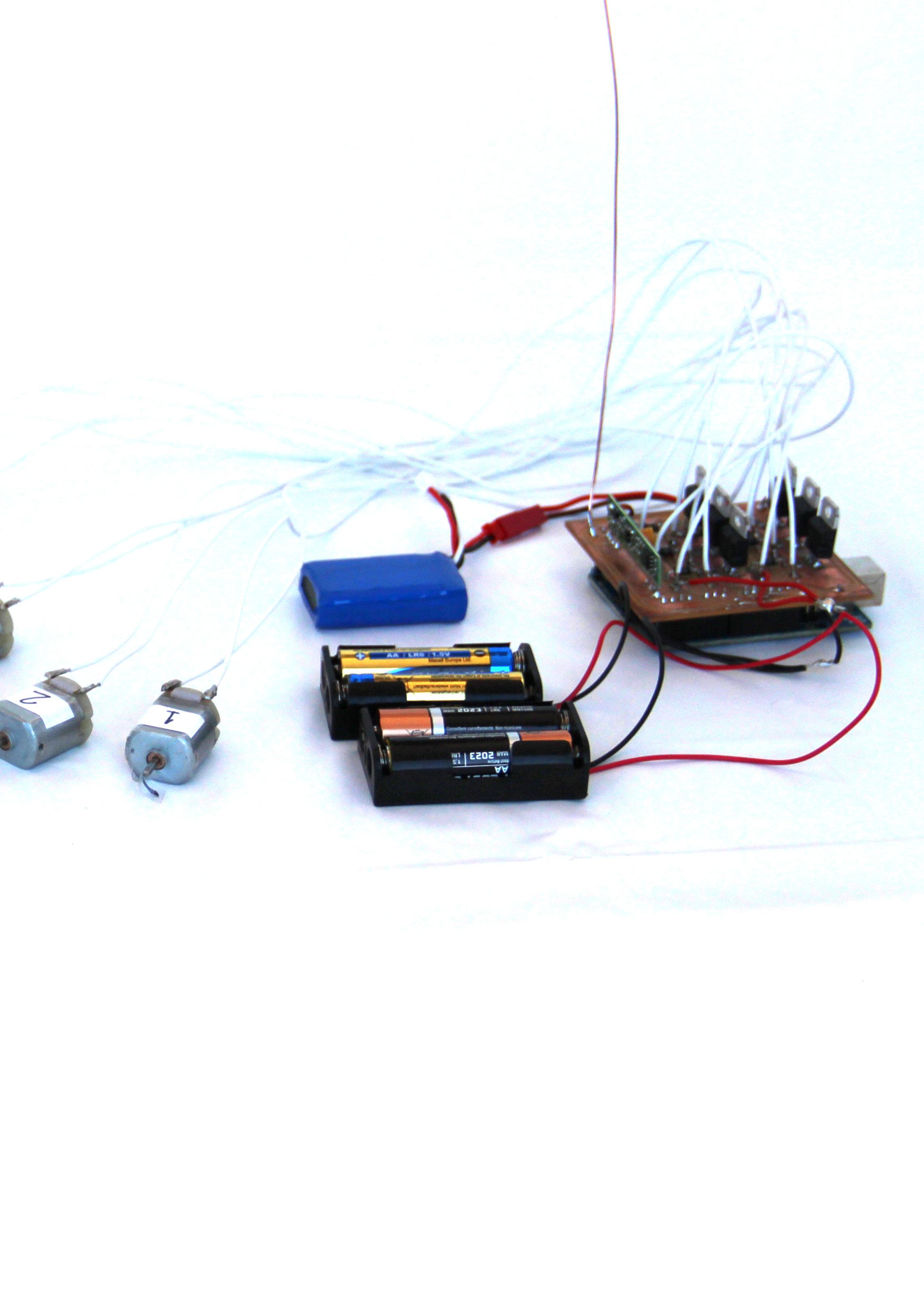
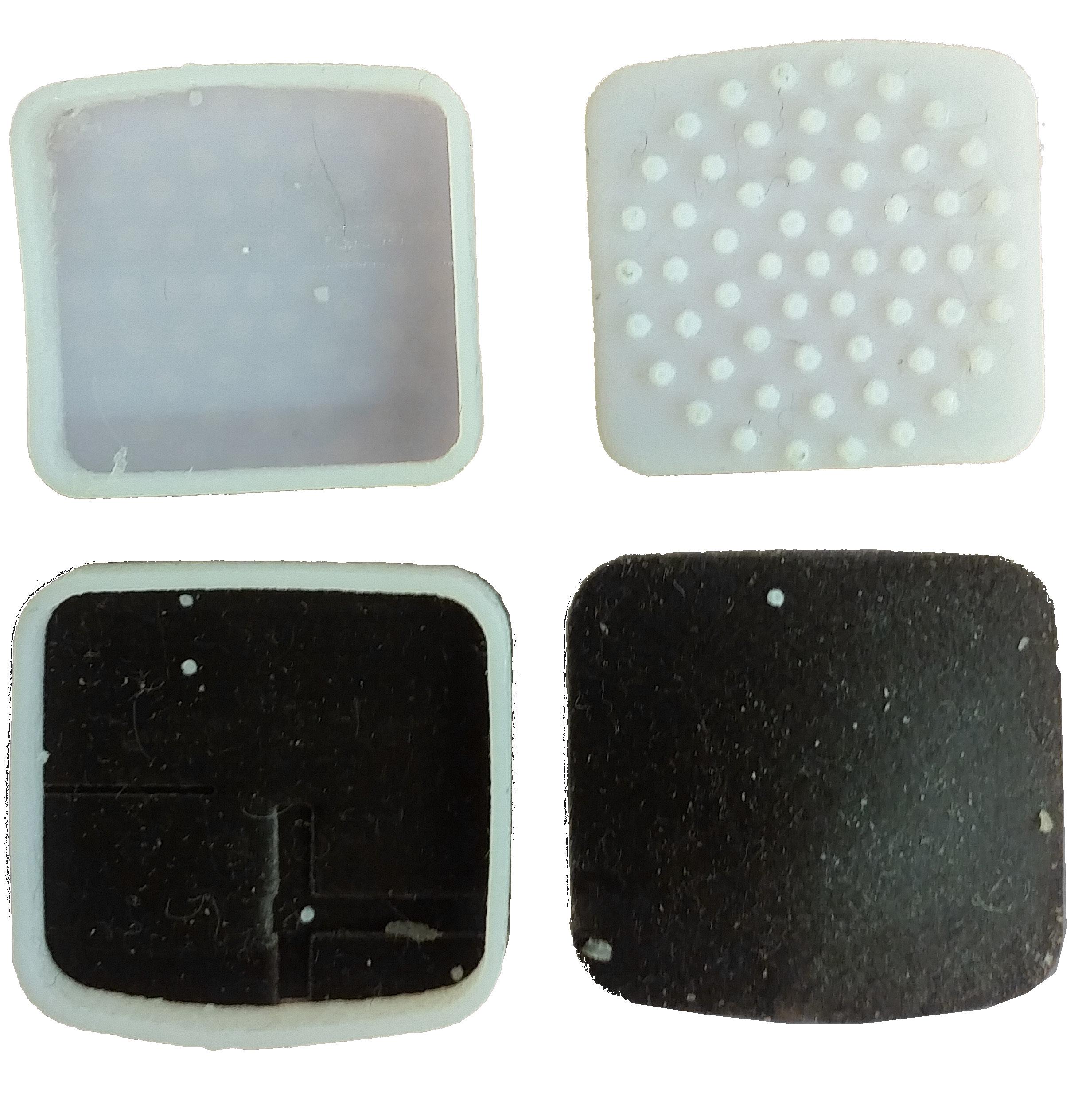
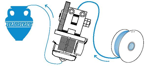
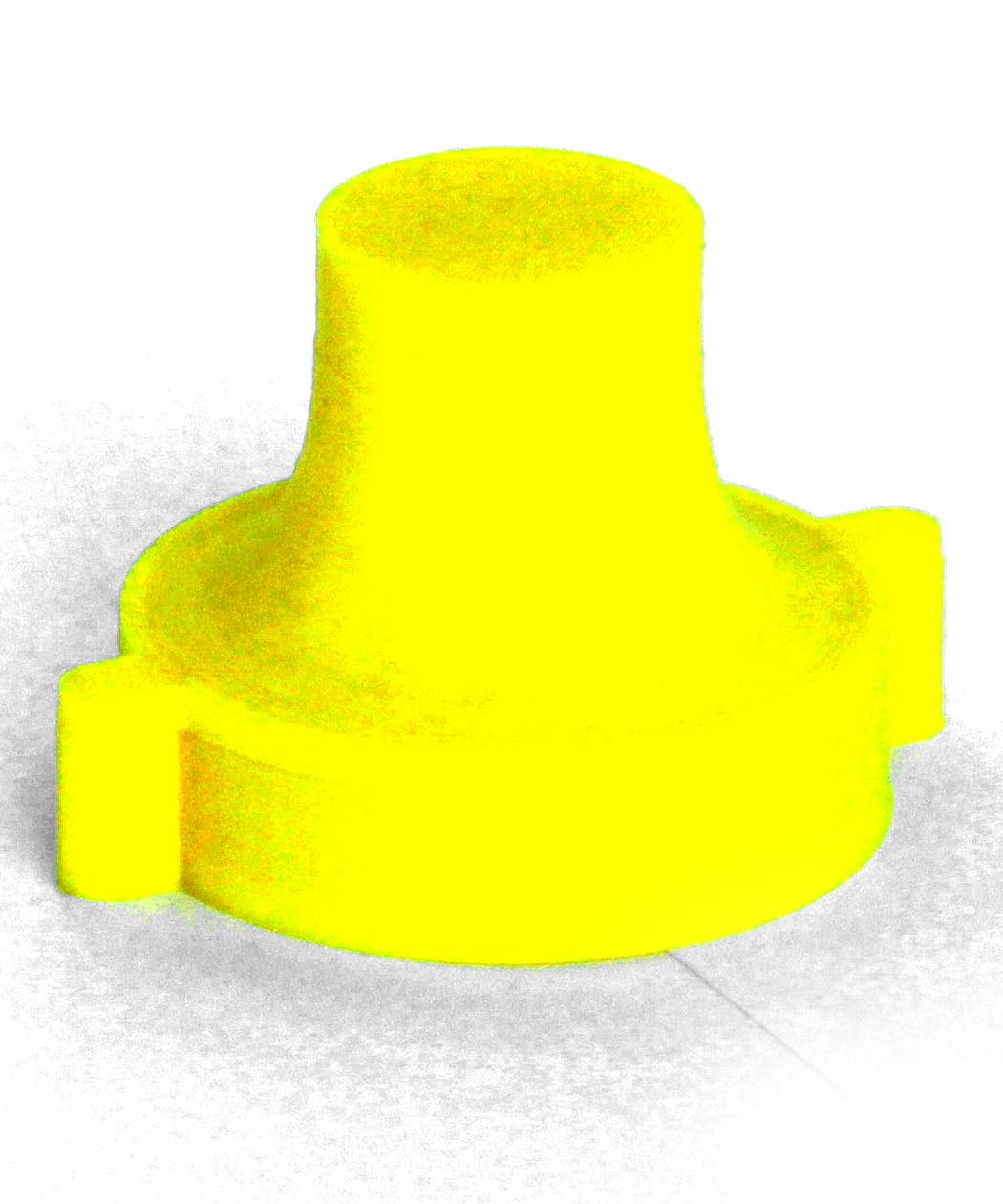
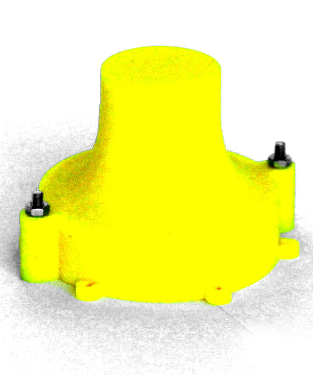
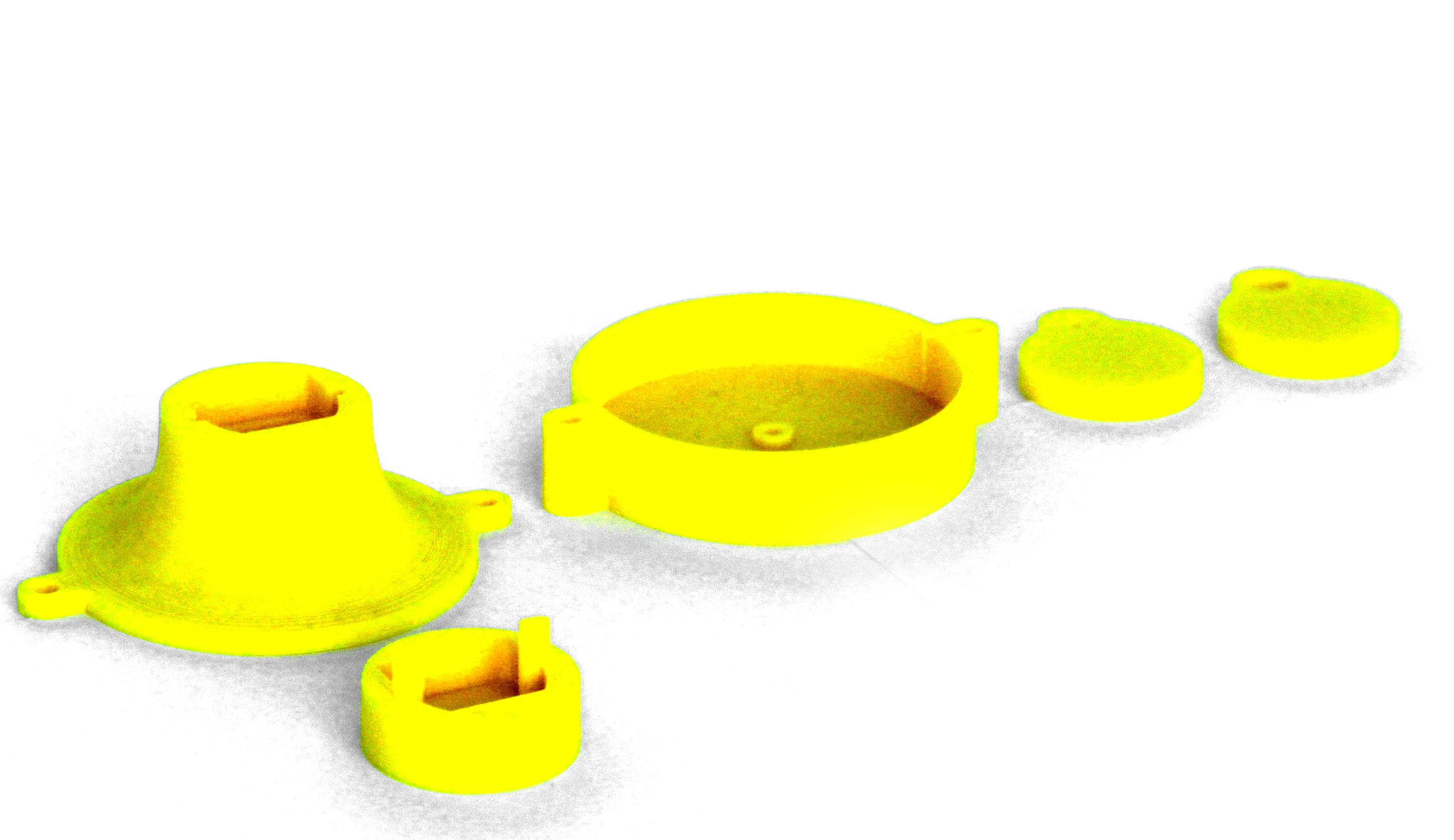
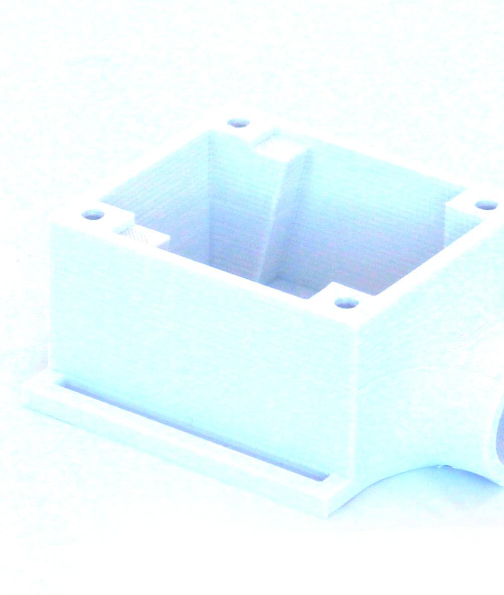
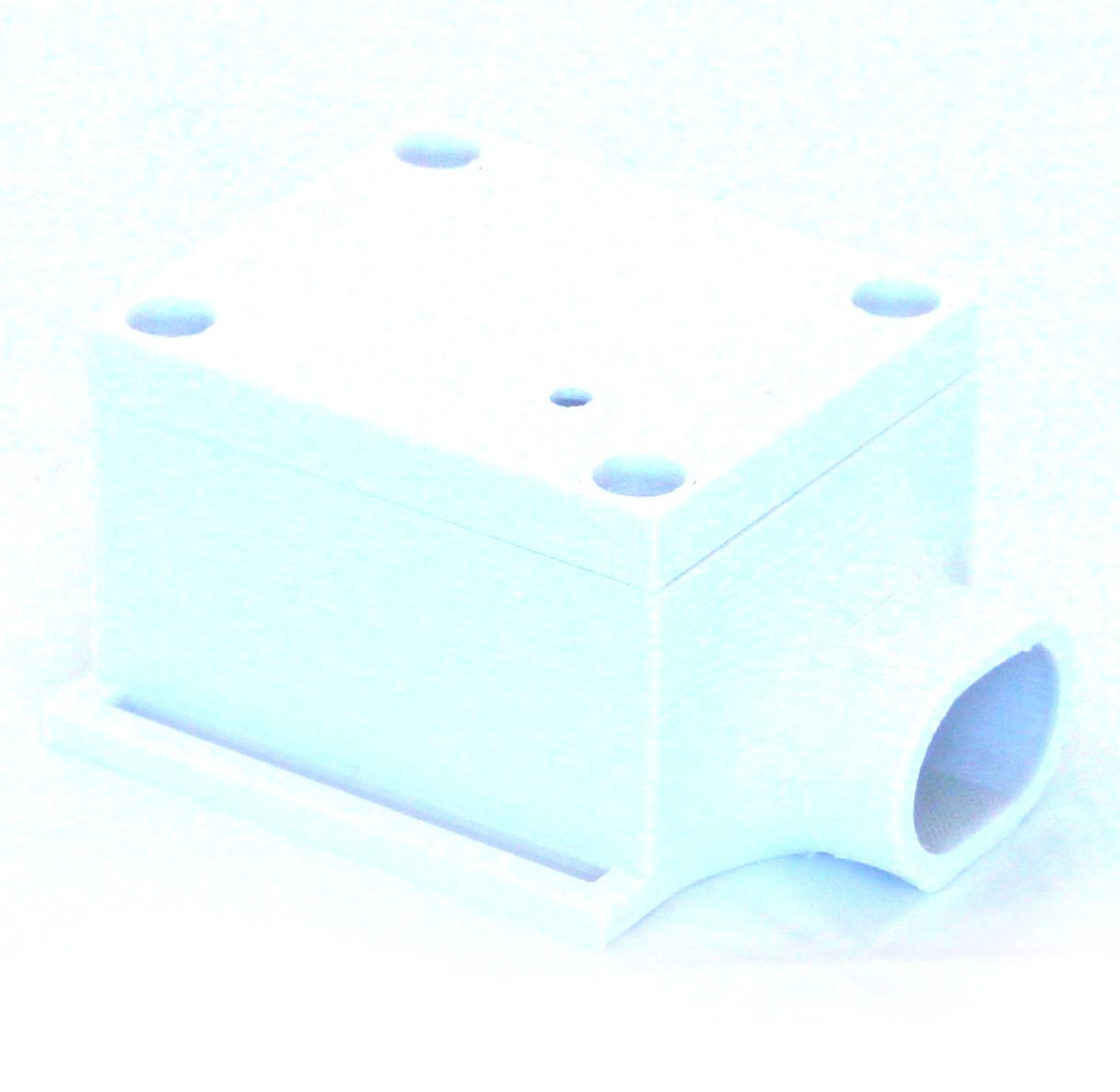
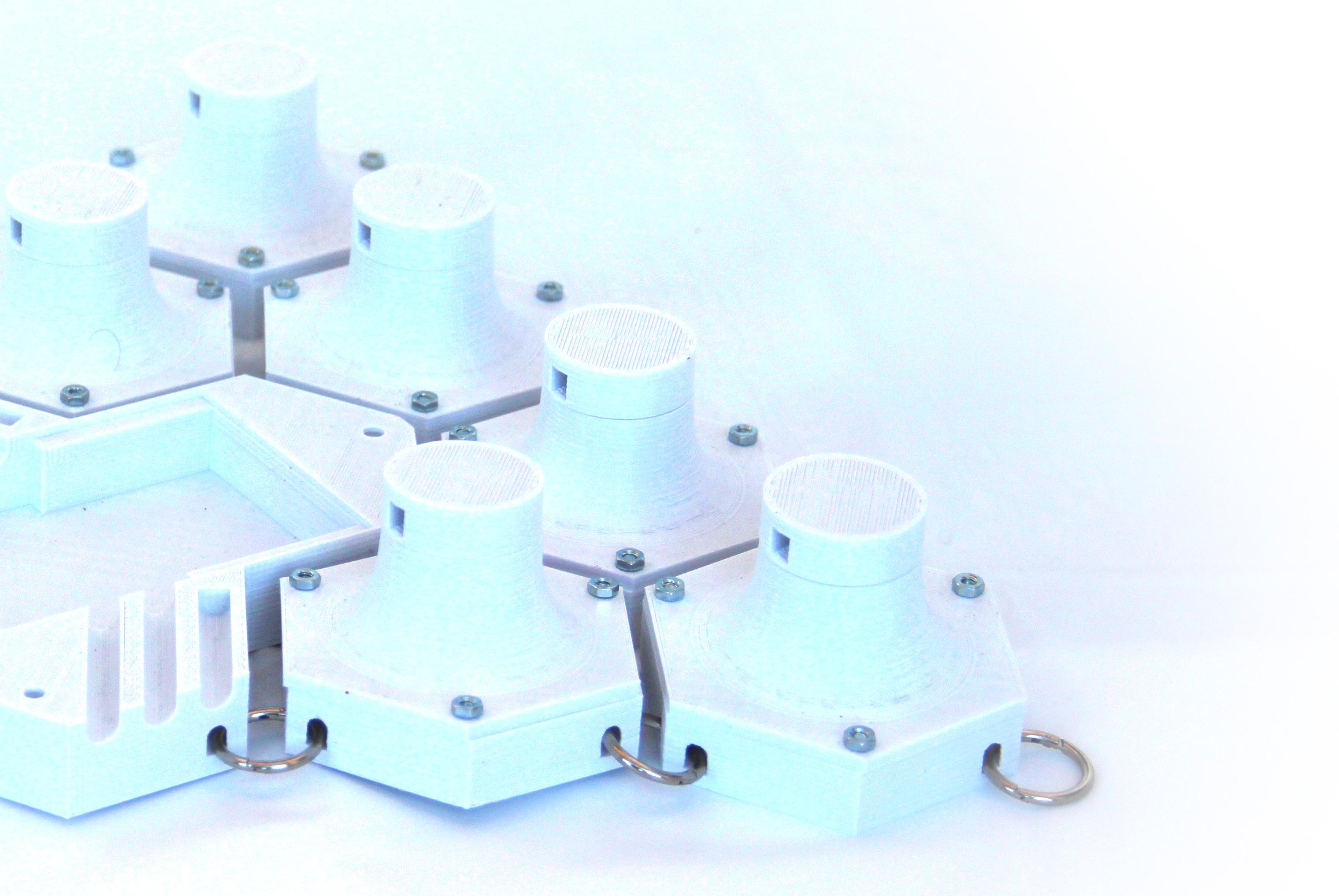
For fabricating the cases of the DC Motors, the Arduino‘s and the produced Shields, it was created a series of compartments using a 3D Prin ter. This option was choosed due to the geome try that would be created, and the possibility to change and inprove the final result easily.
interface sho wing the desired geometry to be 3D printed.
The method of 3D Printing used was an aditive one, using PLA filaments.
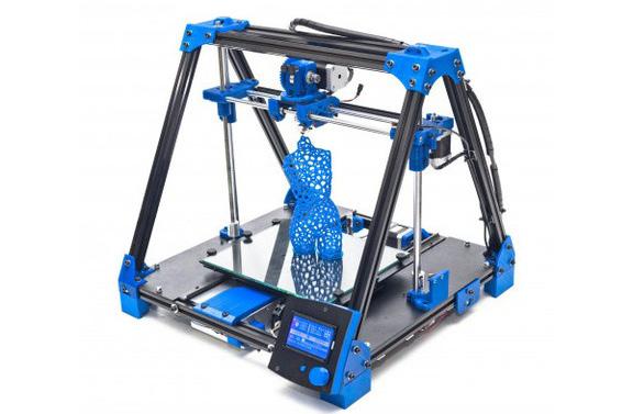
RepresentationMiddle: of the 3D printer process used. Bottom left: BCN3D logo. Bottom right: 3D printer used to make the components.
The 3d Printer was the BCN3D+, an open hard ware based on the mechanic of the RapRap Prussa, developed by the Universidad Politecnica de Catalunya and assembled by the author. The file for the machine to print is know as G-Code. This file is a series of numbers that represent the position of the nozller and the speed that the extruder need to go to the cur rent point from the previous point. this speed determines the size of the heated fillament. The G-Code was generated using the Slic3r software, a free software that generate the G-Code file, by configurations defined by the user, such as height of each layer, temperature, percentage of the fill of each solid, style of the fill, etc. The Slic3r software need as a basic input the base geometry to be 3d printed. This geometry was made using the Rhino software, but could be generated by any major 3dD modeler.
Hardware Method of Fabrication
06|06
98
Top TypicalTopSlic3rleft:logo.right:Slic3r
99

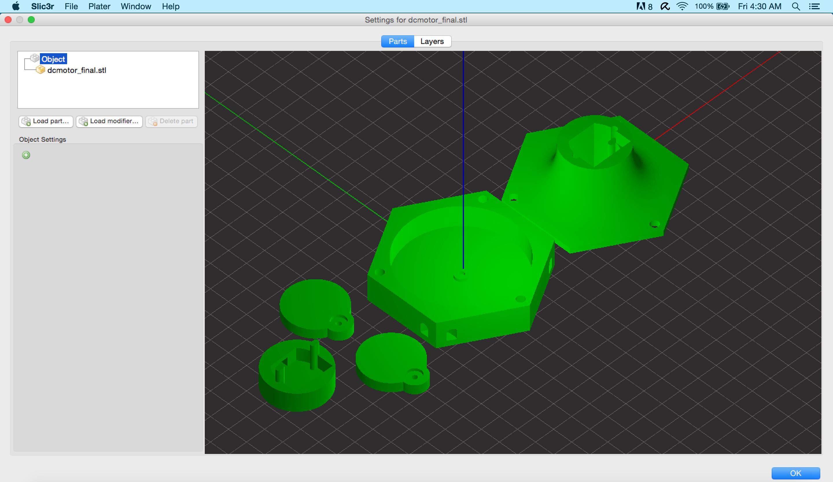
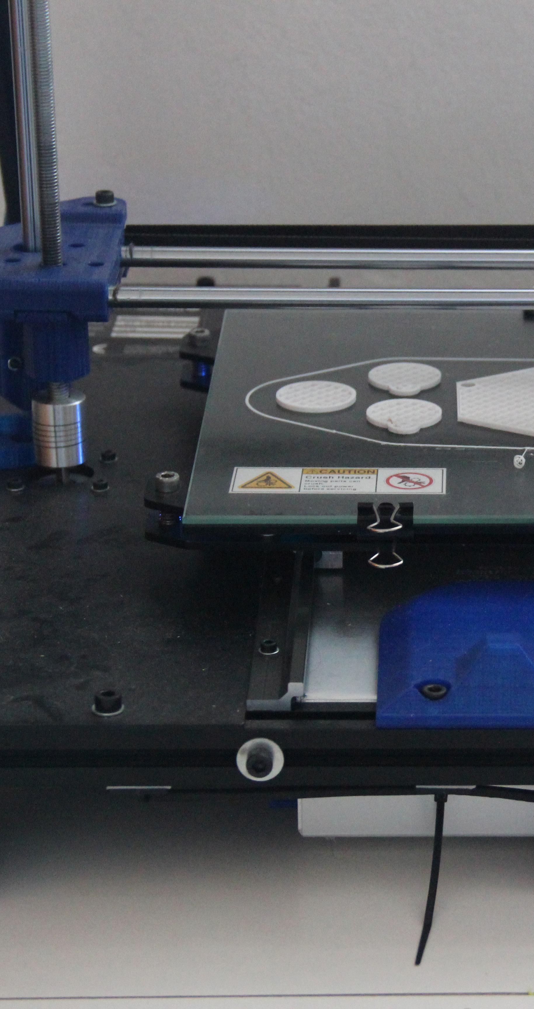
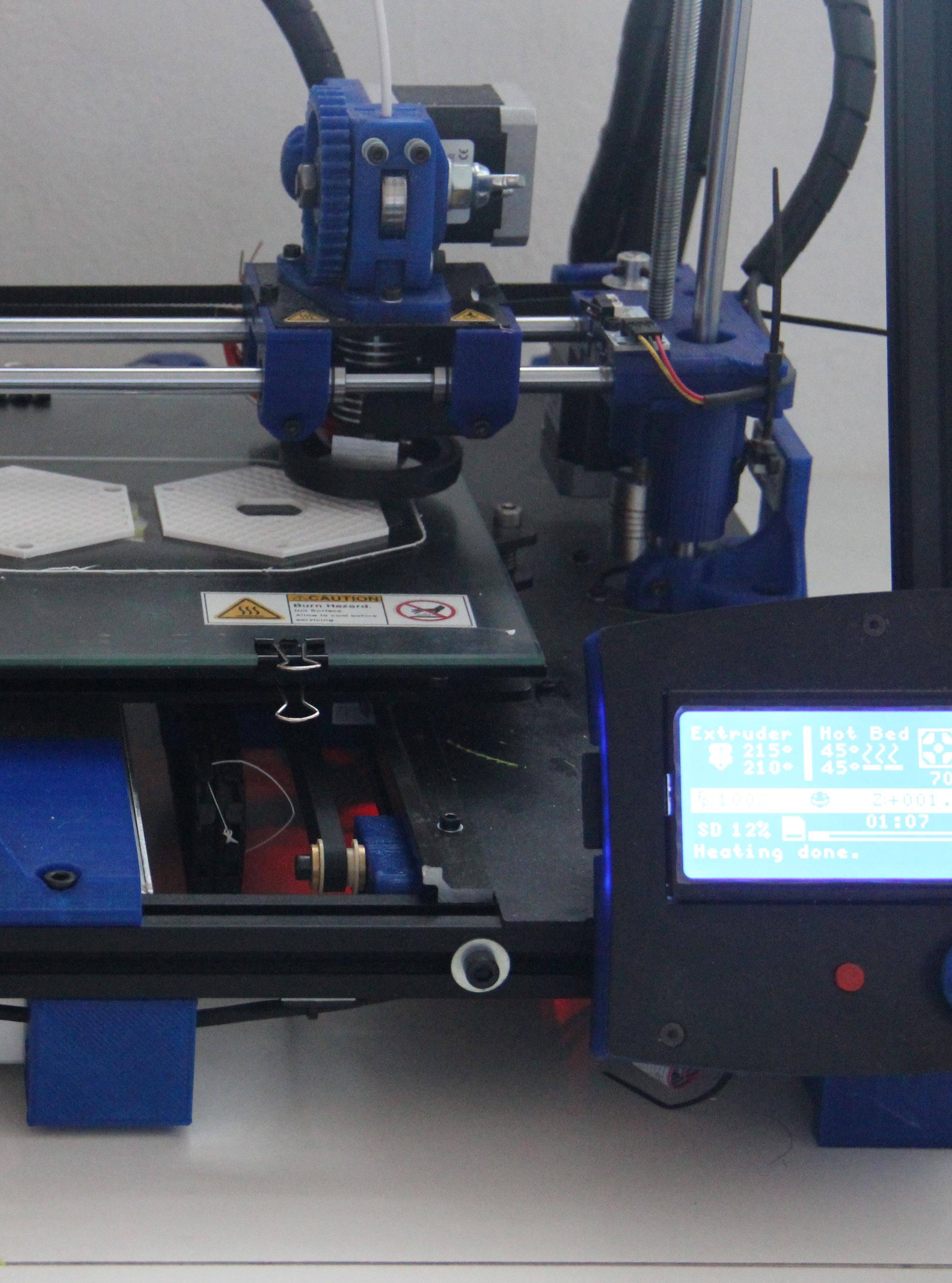
100 3D printed fabricating the back components, making layer by layer the desired geometry by adding the heated and melted PLA fill ament, which will be colled and become solid in the base.
101
3.
5.3.1. 6.4.2.
-
5.
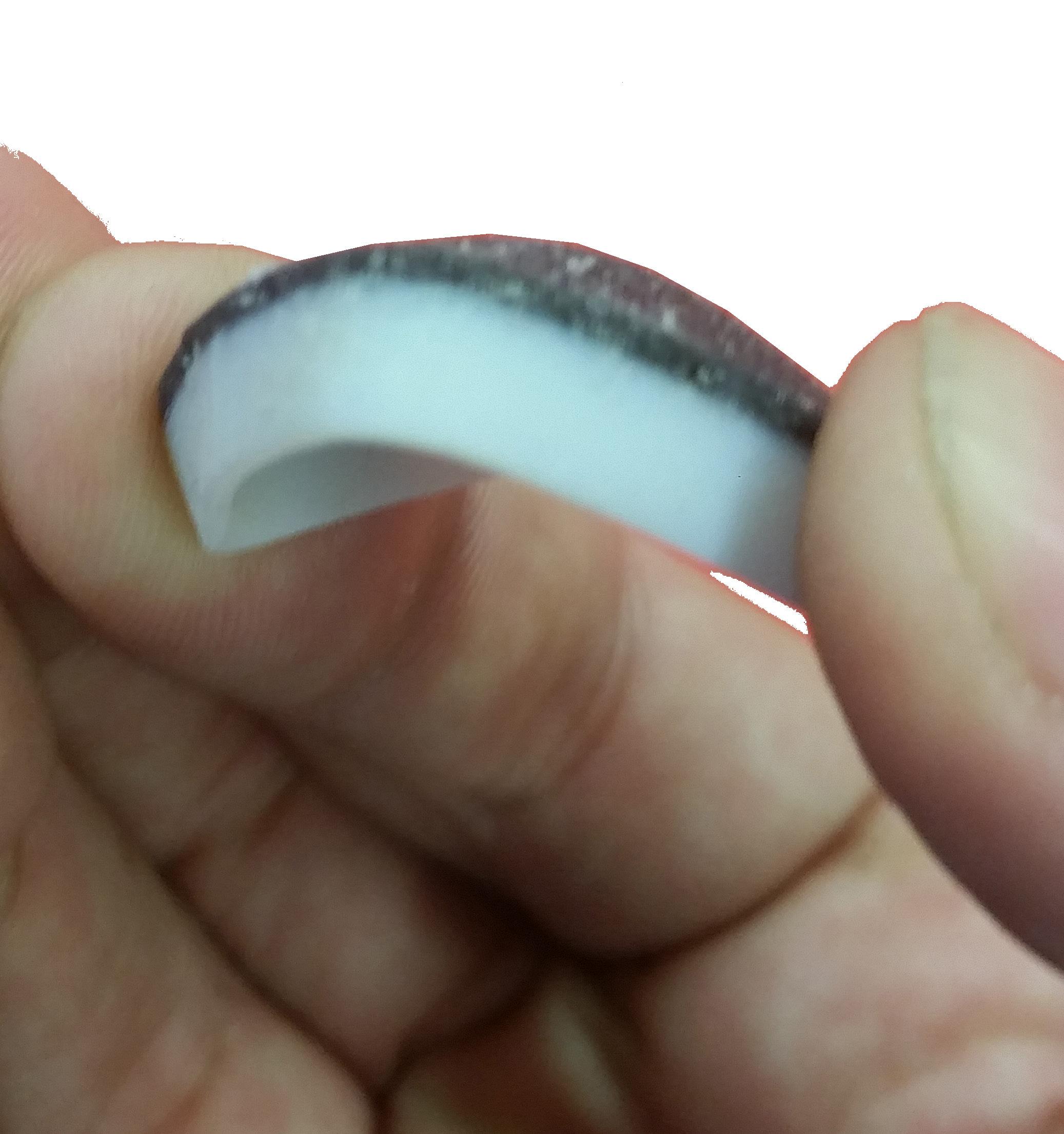
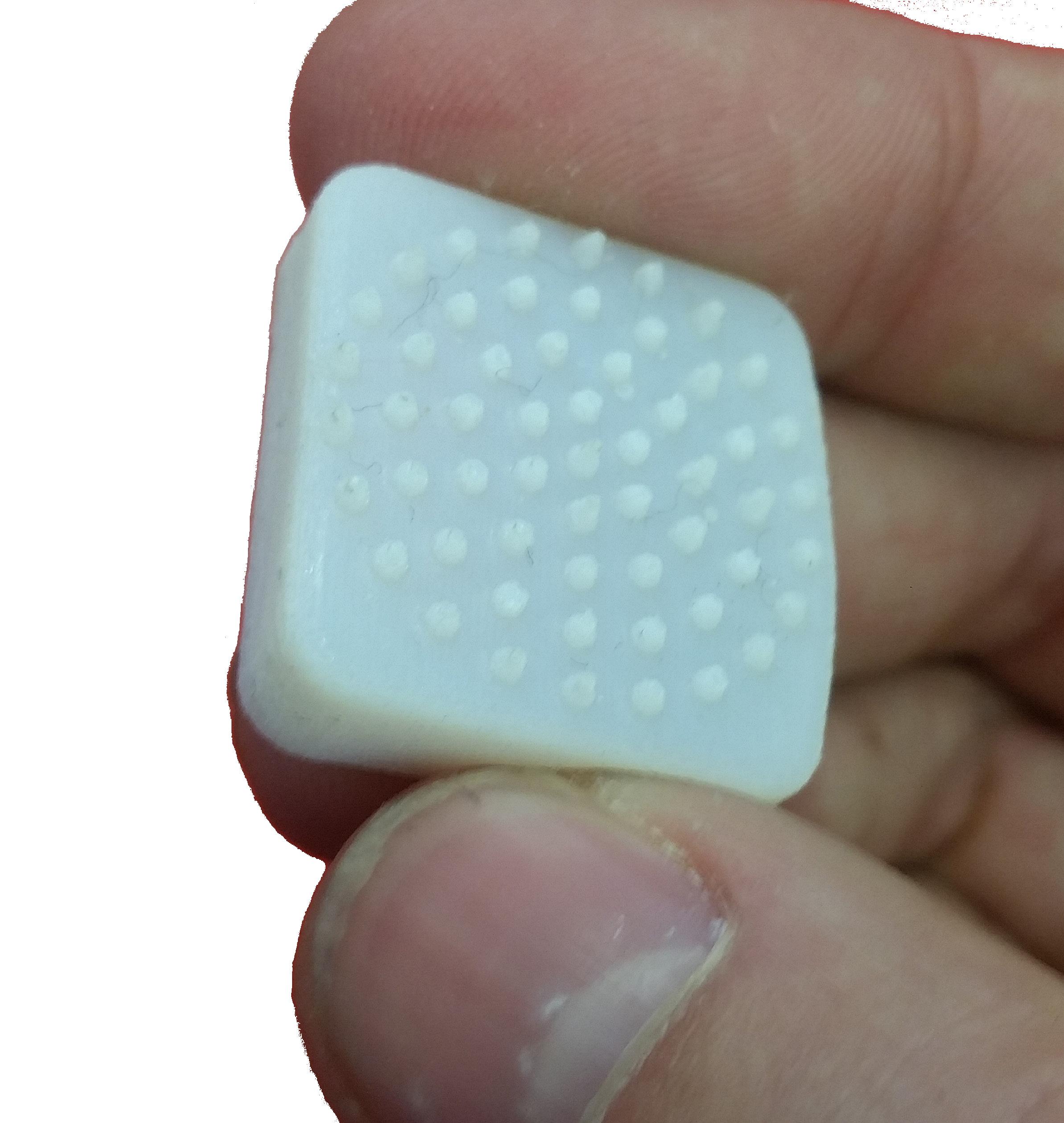
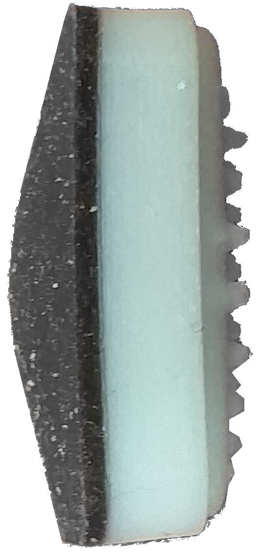
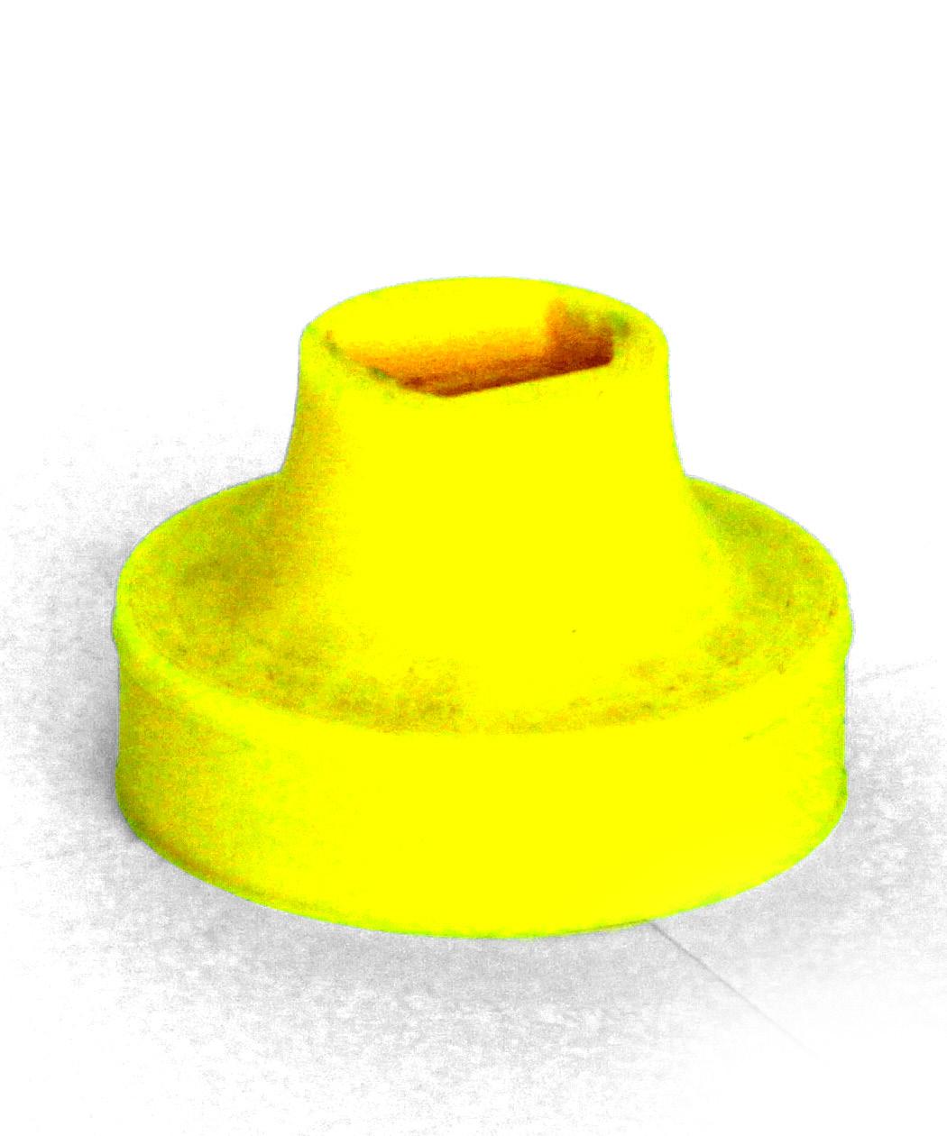
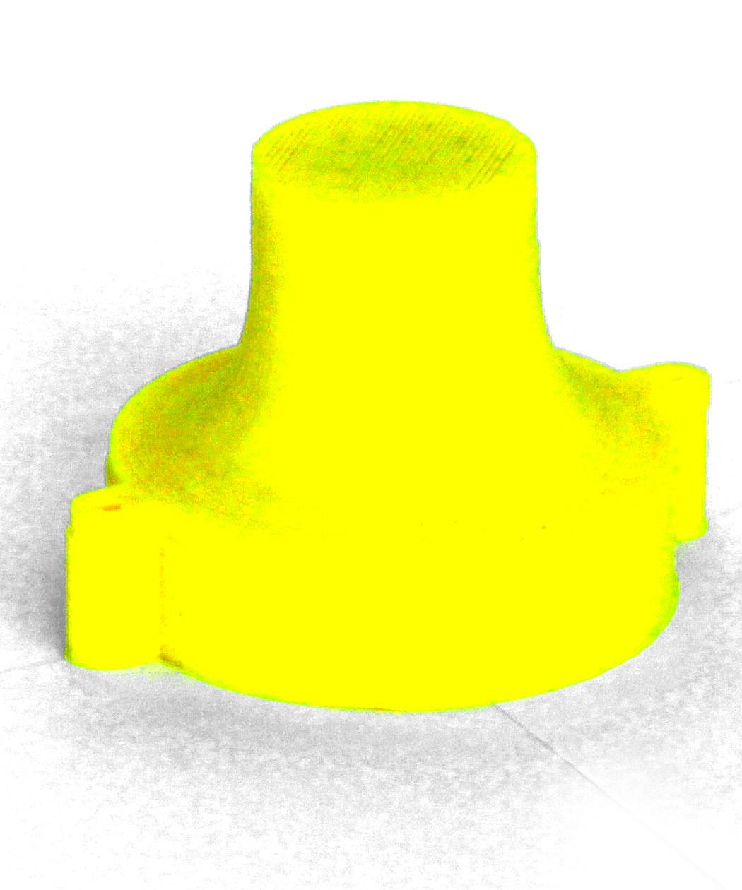
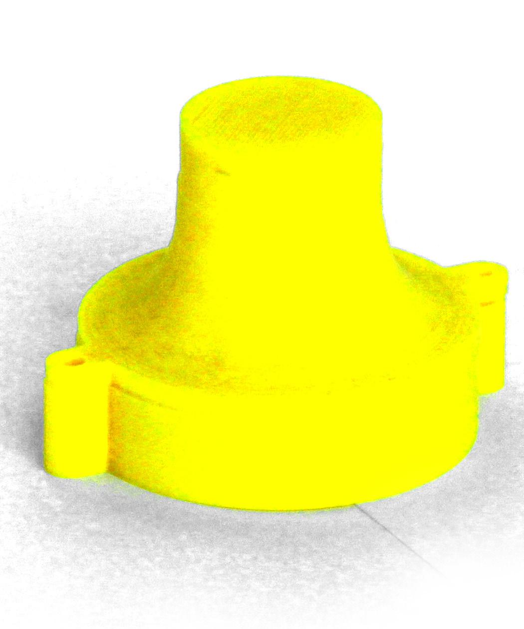
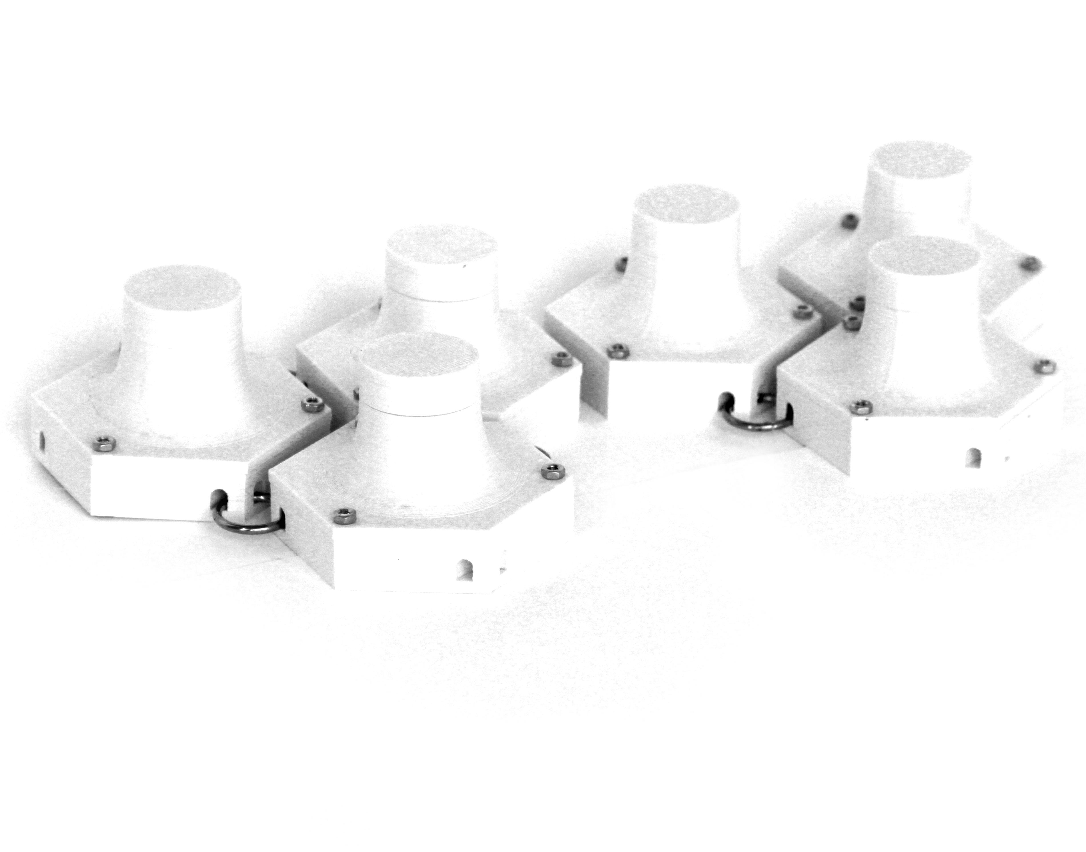
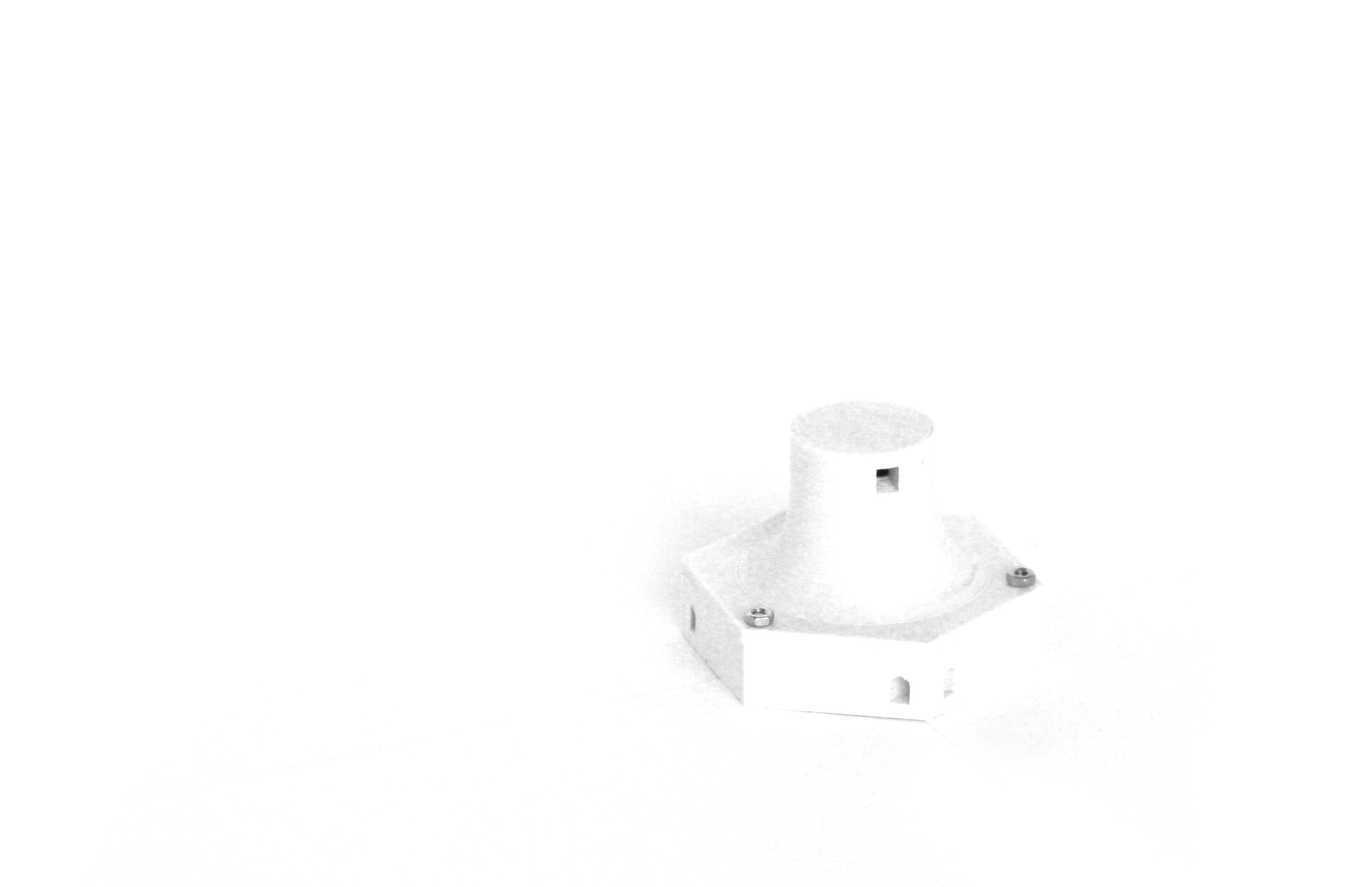
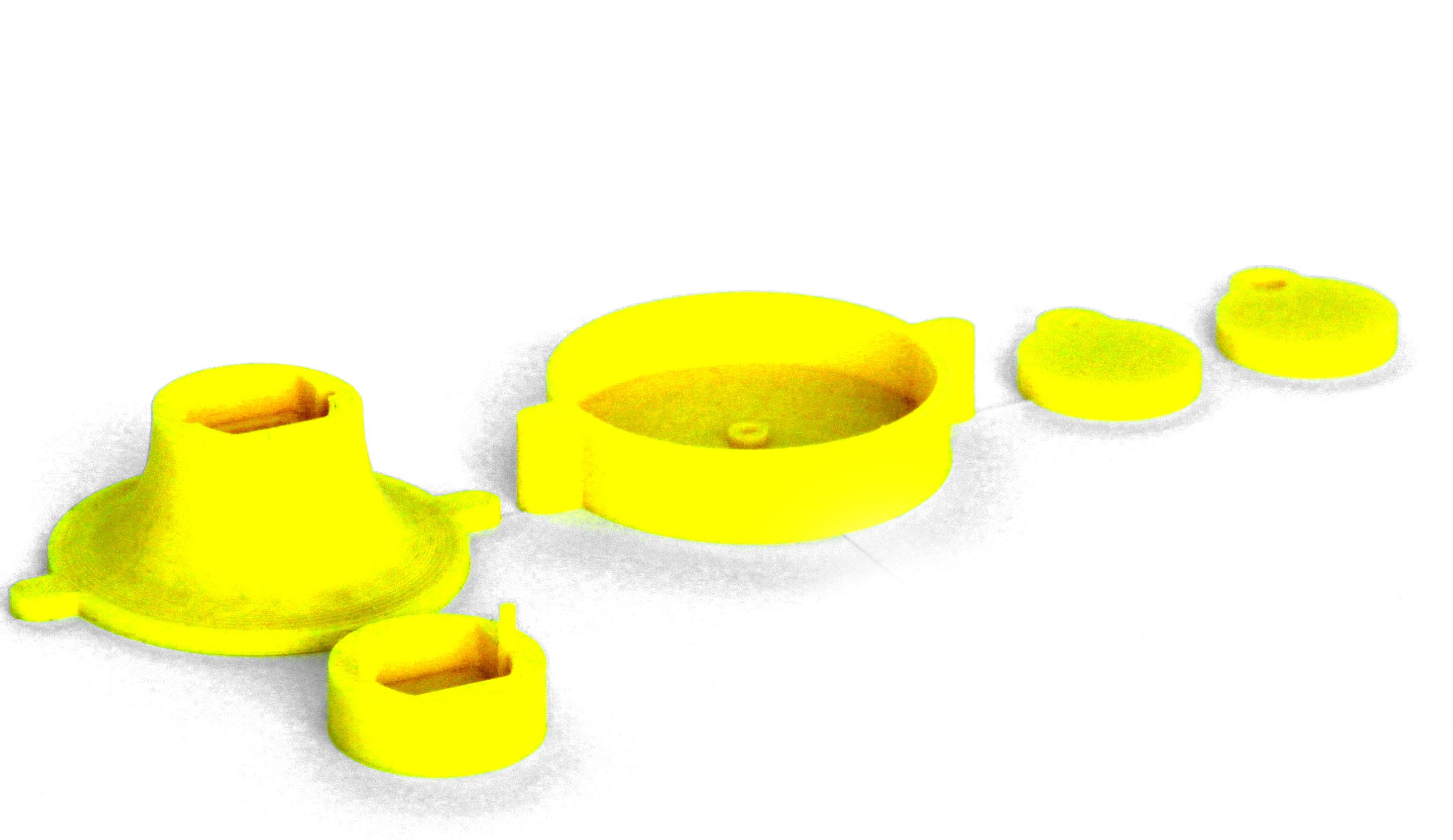
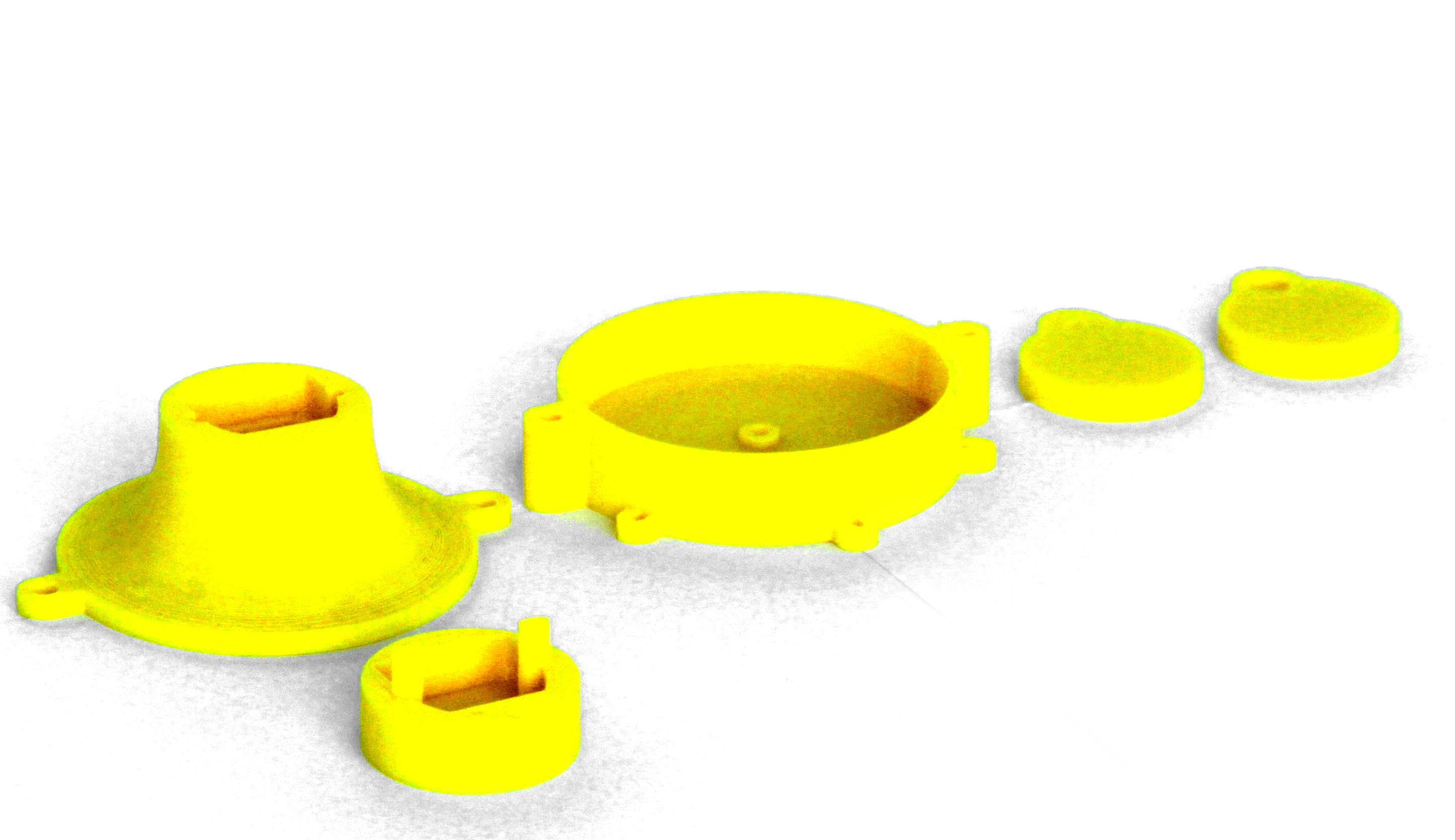
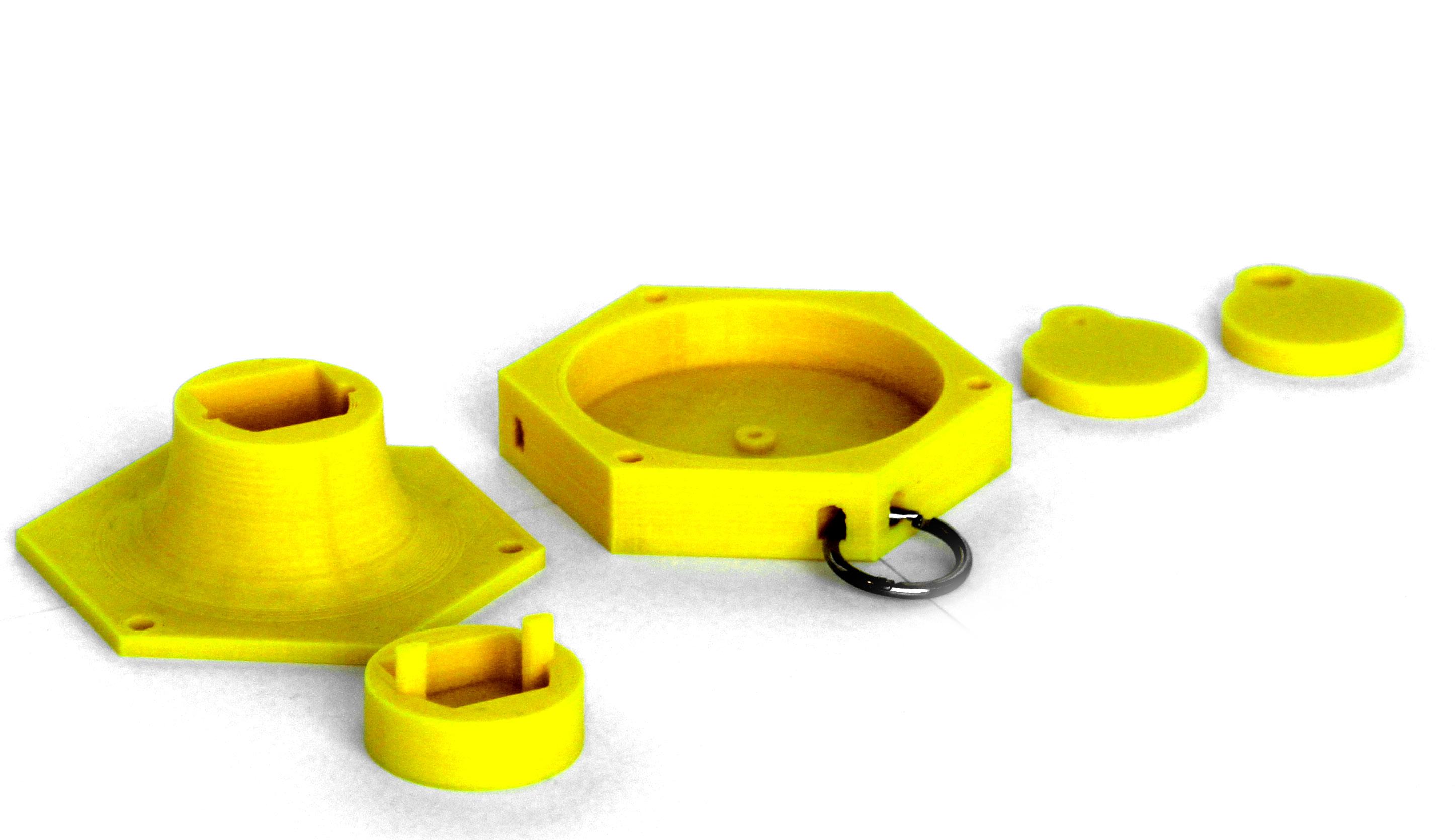
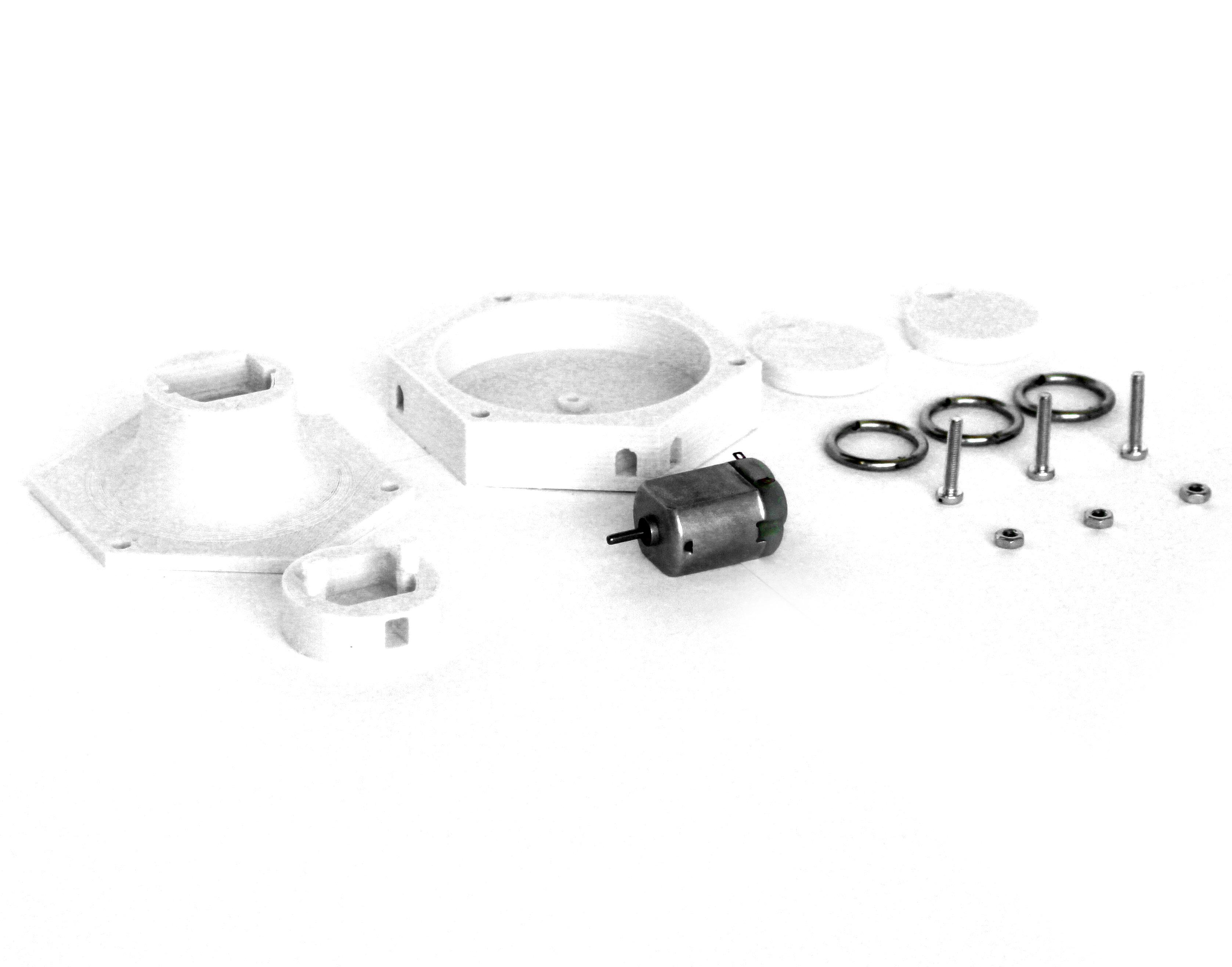
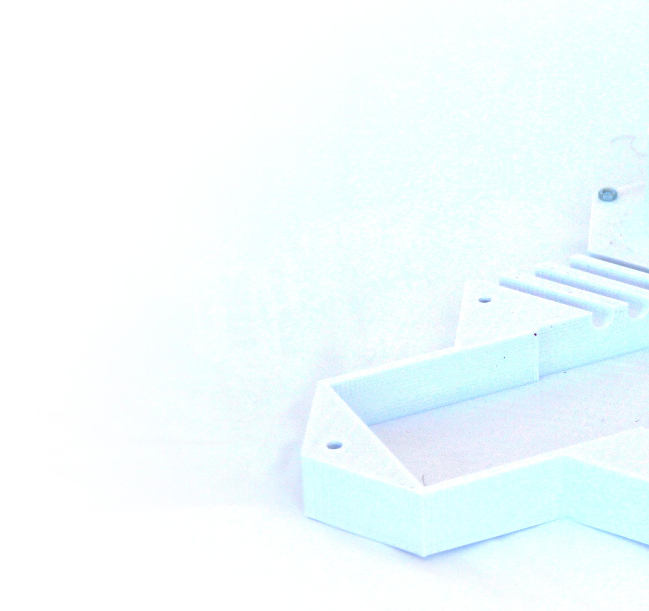
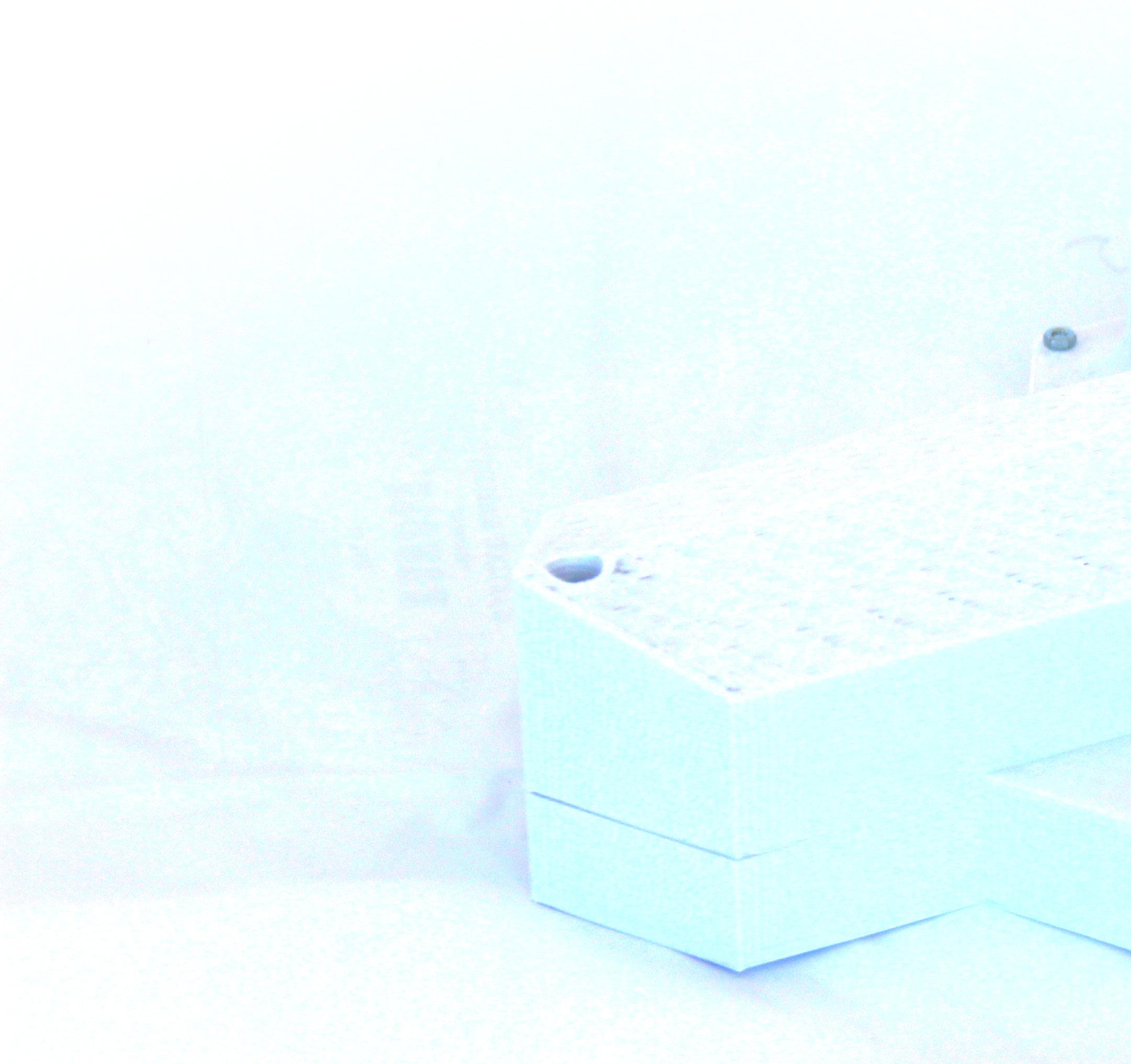
The whole process of de veloping a module to fit the DC Motor consisted on designing, 3D printing, and improving. At the photos it is possible to see this evo beggining of the DC Motor case; Designing a cap and a place to put the screws; Making the holes for the screws; Adjusting the size of the holes and the cap; Making little holes for se wing at a fabric; Change the overall form to a hexagonal form and small holes for pacing by the rings; and The final result of the ele ment, together in the net.
6.
2.
7.
4.
102 Hardware Evolution06|07
1.lution.The

103 7.
6.
7.
5.
4.3.2.1.
104 Also, the inside of the DC Motor compartment was developed carefully.
4.
1. The beggining of the DC Motor case; Designing a cap and a place to put the screws; Making the holes for the screws; Adjusting the size of the holes and the cap; Making little holes for se wing at a fabric; Change the overall form to a hexagonal form and small holes for pacing by the rings; and The final result of the element, with all the components of each unit.
2.
3.

105 7.6.5.
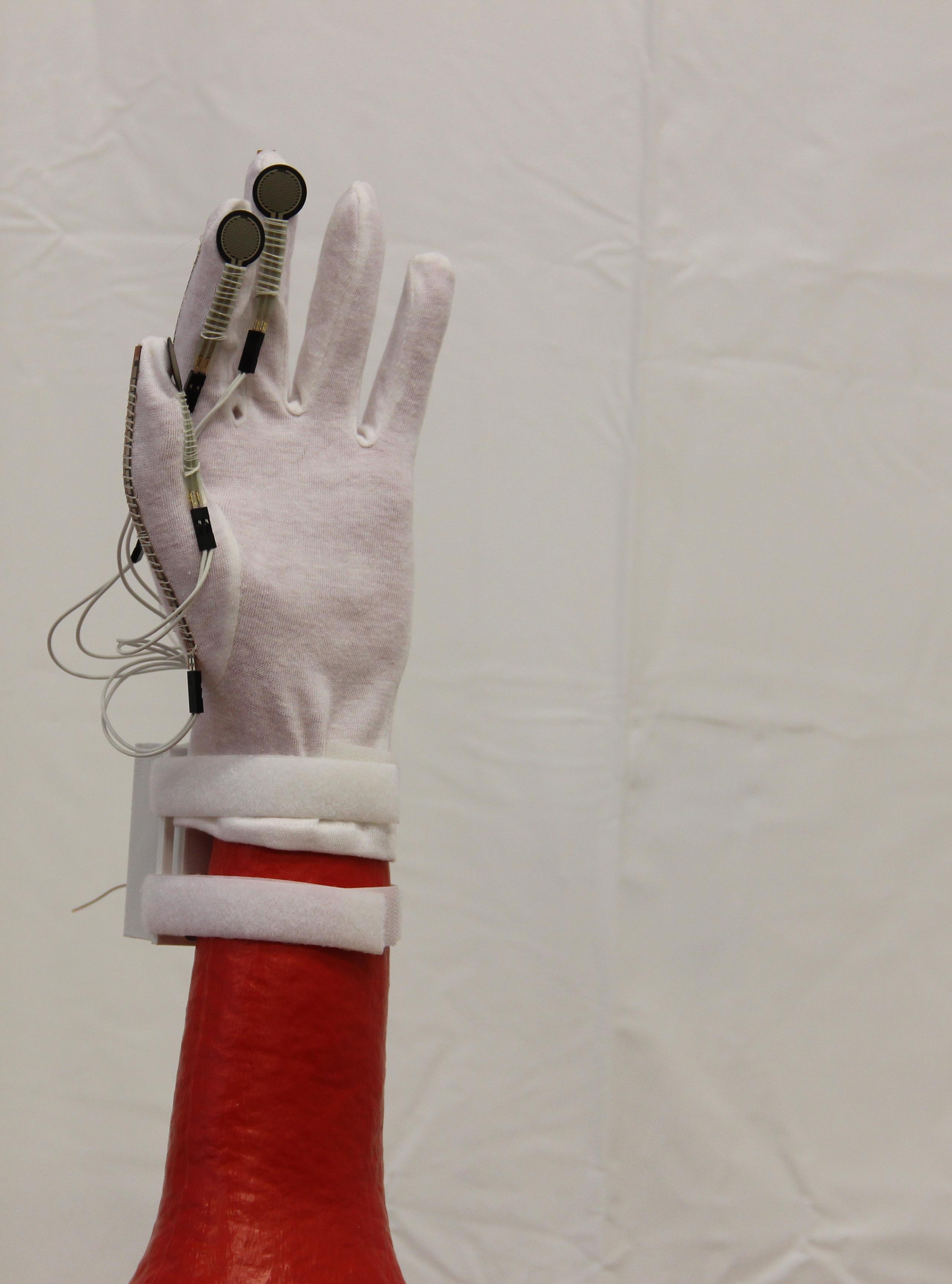
1. The first step was to de velop the clips for one fin ger, so the tip of the finger would be covered; 2. The clips were improved; 3. In order to make the user have more contact with the enviroment, the suport for the pressure sensor was opened; 4. The design changed and at this stage, the pressu re sensor and the bending sensor would have holes; 5. Instead of preasure clip, a screw was used; 6.Some improvements were made; and 7. The cotton fabric glove was used since it is flexible and more user friendly.
5.3.1. 6.4.2.
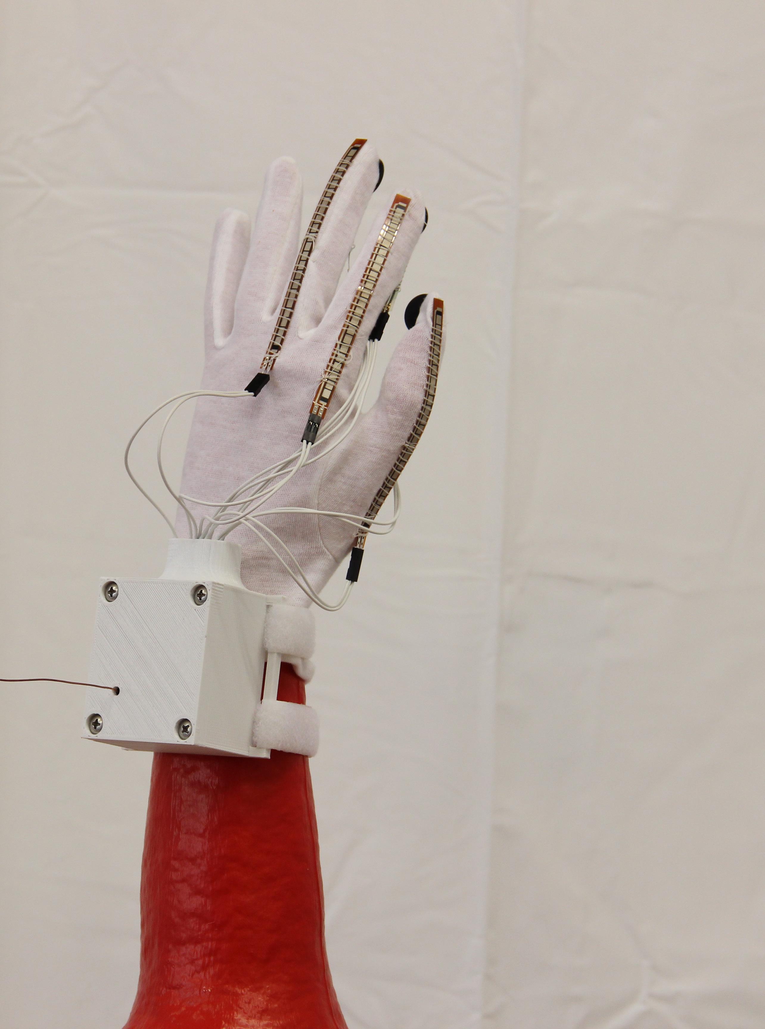
106 Also for the clips that would hold the bending sensors was developed clips. The evolution can be seen at the images.


107 7.

108 The final result of the 3D printed glove eletronics compartment open and closed.
109

110 The final result of the 3D printed back eletronics compartment open and closed.
111

113 Final Prototype07
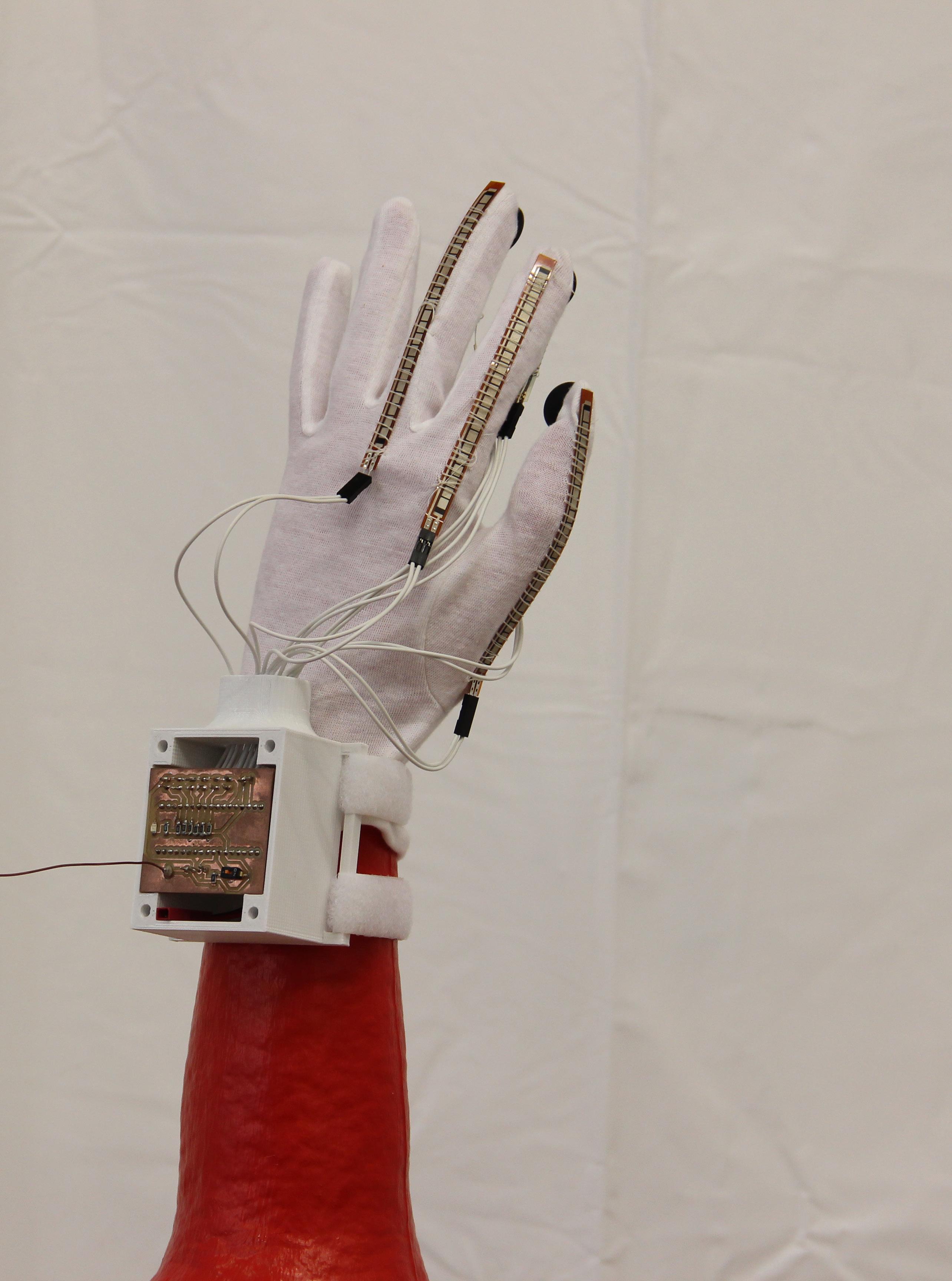
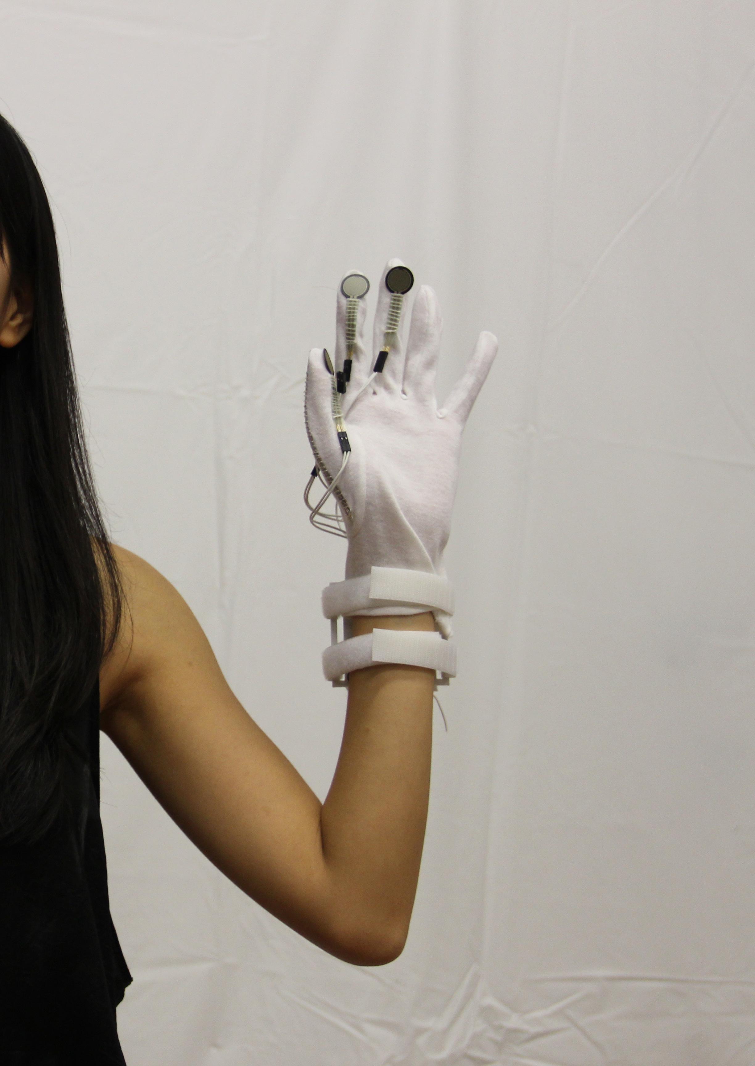
View of the palm of the glove device, showing the velcro stripes to attach to the wrisps, and the three pressure sensors sewed to the finger tips of the glove.
114

115
116
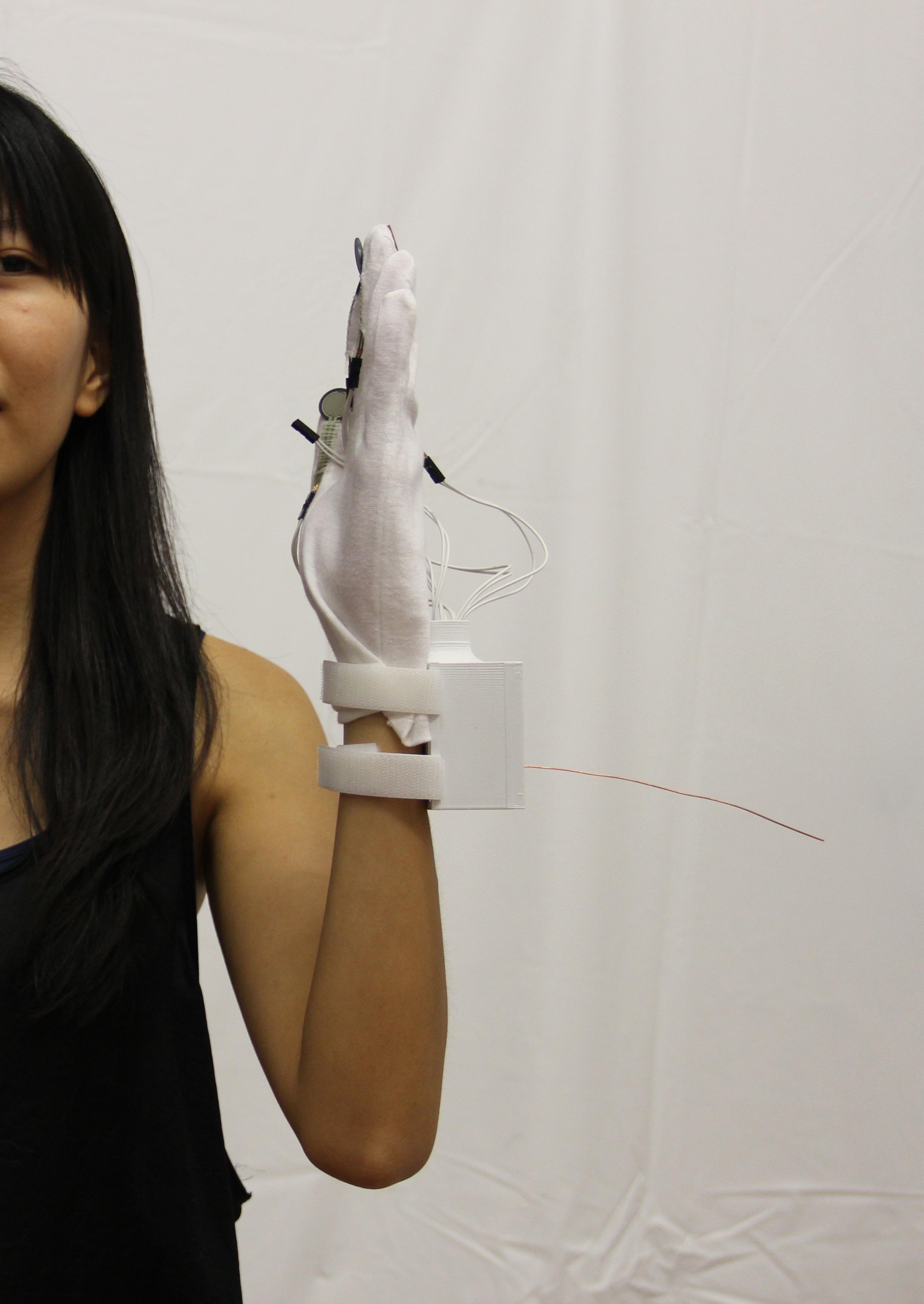
View of the top part of the glove device, showing the 3D Printed compartment, attached to the wrists with velcro, closed with screws, with the wires exit side, which collect the wires that are connected to all the sensors, including the ben ding sensors that are viewed from this side.
117
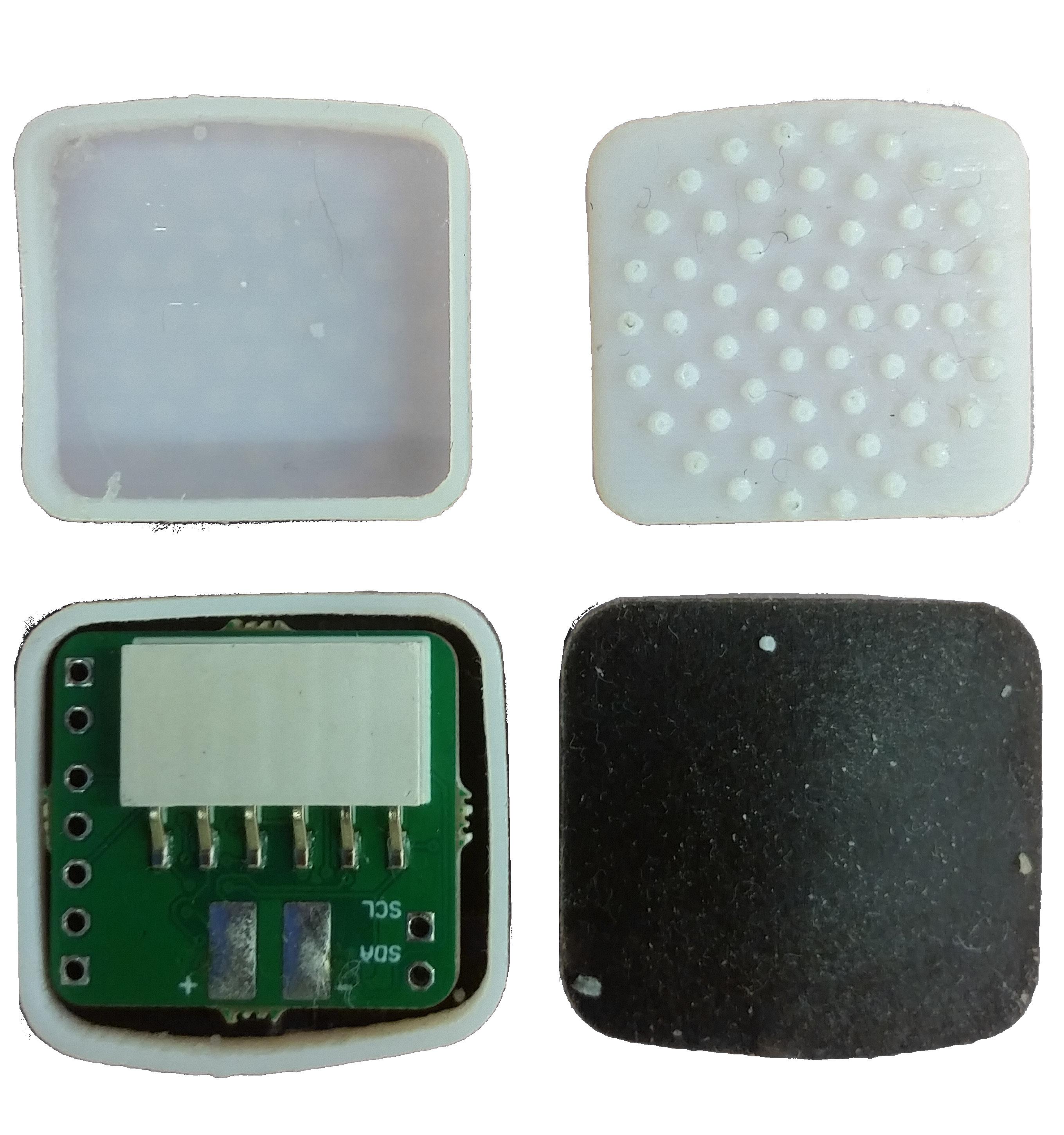
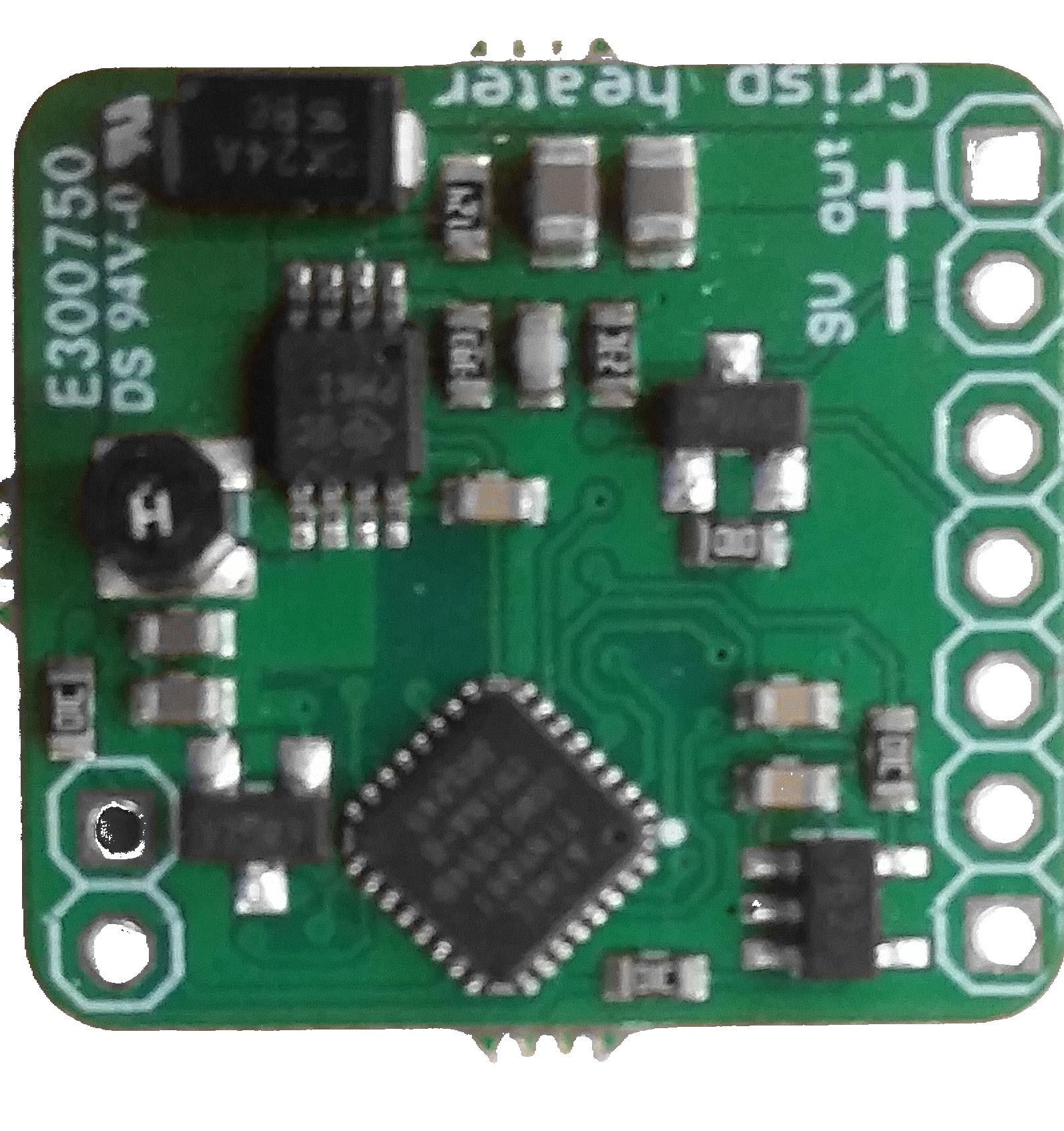
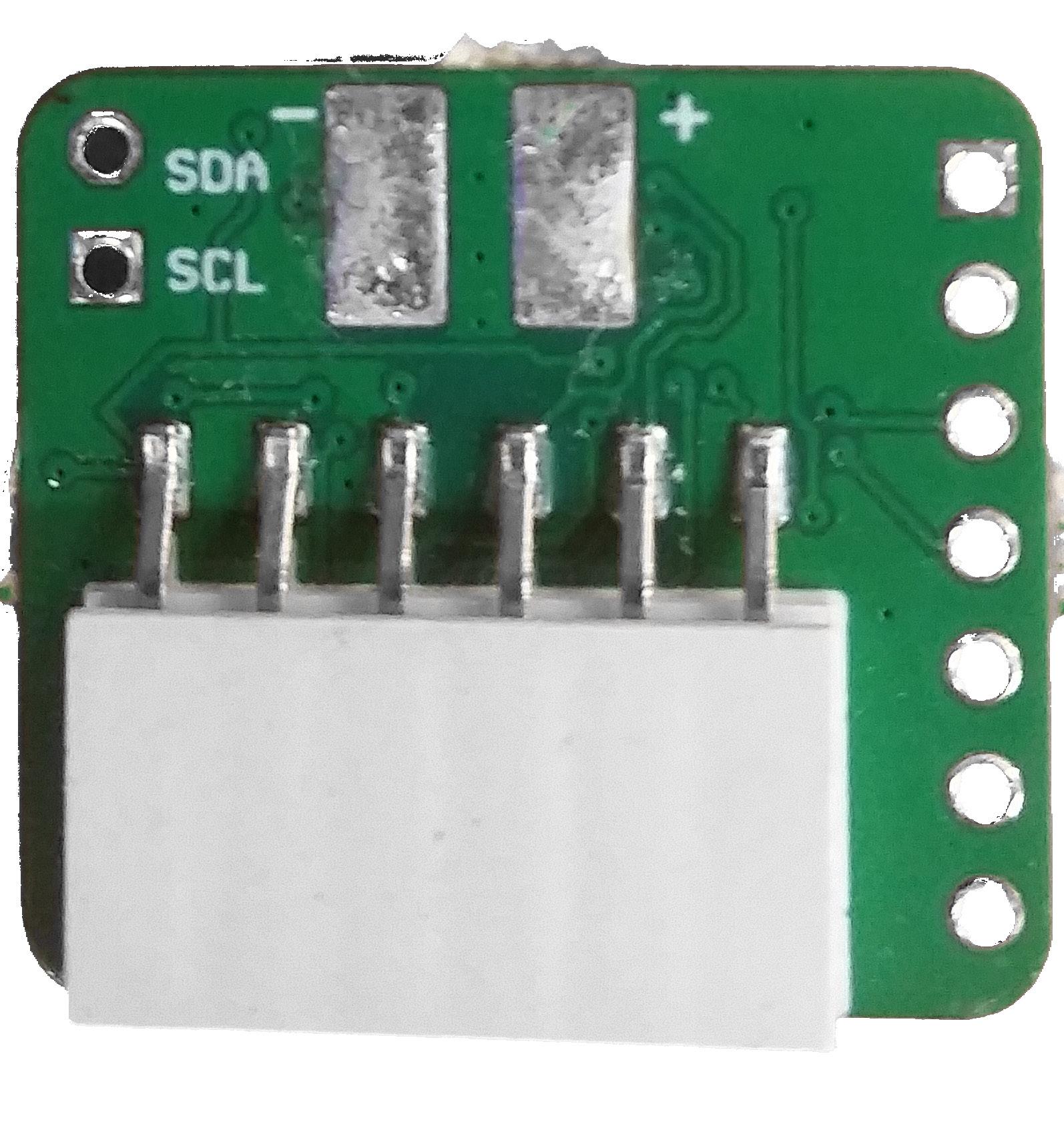
118 View of the top part of the glove device, showing the 3D Printed compartment oppened showing the fabri cated shield with the switch to start sending the infor mation collected from the sensors and processed by the Arduino MICRO.
119
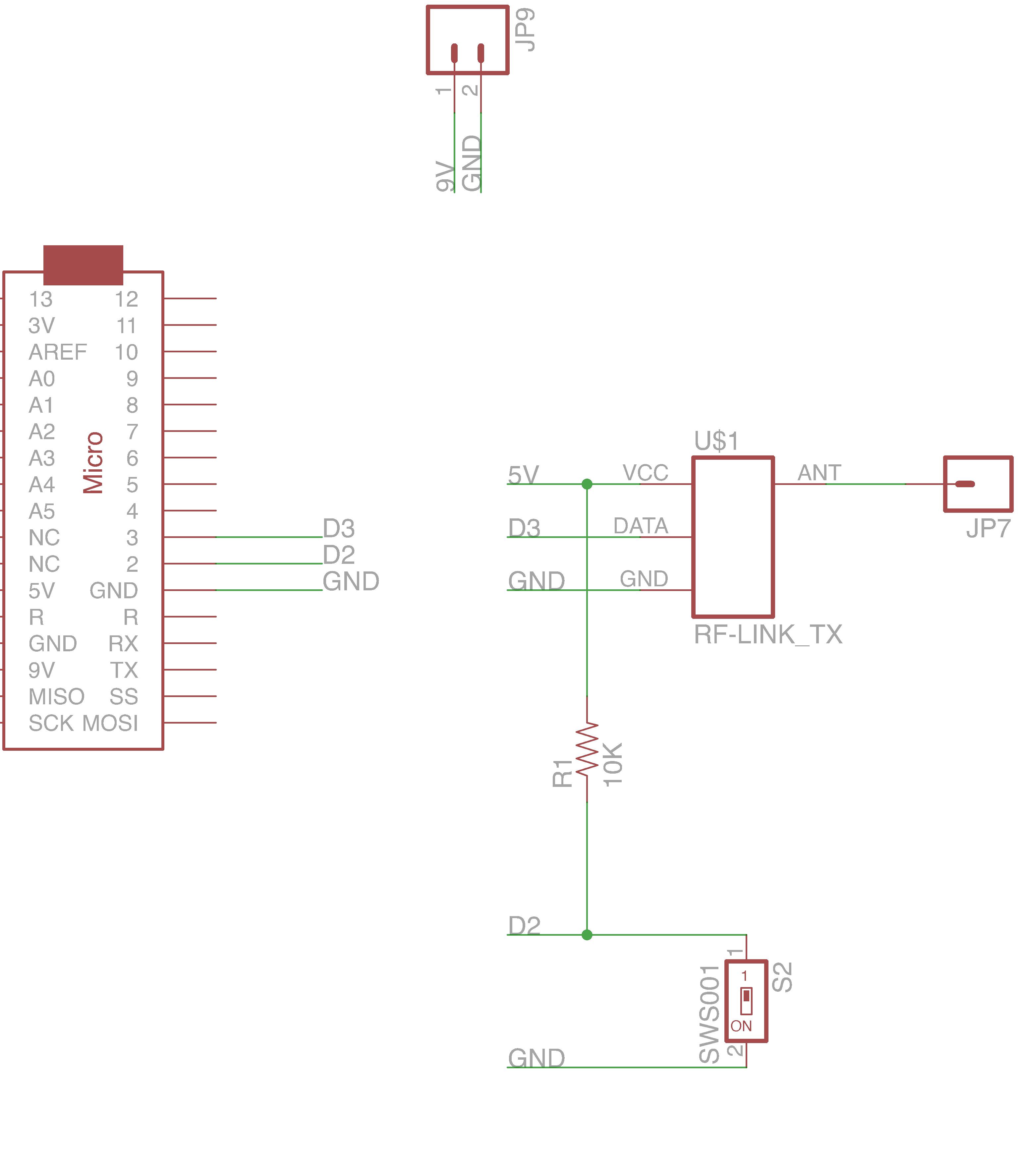
120 Schematic of the Arduino MICRO Shield produced.

121
122 #include <VirtualWire.h> int Sensor1Pin = A0; int Sensor2Pin = A1; int Sensor3Pin = A2; int Sensor4Pin = A3; int Sensor5Pin = A4; int Sensor6Pin = A5; int ledPin = 13; int Sensor1Data; int Sensor2Data; int Sensor3Data; int Sensor4Data; int Sensor5Data; int charSensor6Data;SensorUNOCharMsg[21];// The string that we are going to send trought rf void setup() { Serial.begin(9600); // LED pinMode(ledPin, OUTPUT); // Sensor(s) pinMode(Sensor1Pin, INPUT); pinMode(Sensor2Pin, INPUT); pinMode(Sensor3Pin, INPUT); pinMode(Sensor4Pin, INPUT); pinMode(Sensor5Pin, INPUT); pinMode(Sensor6Pin, INPUT); pinMode(2, INPUT); // button pinMode(13, OUTPUT);//LED for sending // VirtualWire setup vw_setup(2000); // Bits per sec vw_set_tx_pin(3);// Set the Tx pin void} loop() { if (digitalRead(2) == LOW) {Final code of the Arduino MICRO.
123 digitalWrite(13, true); //Flash status LED to show transmitting // Read and store Sensor Data Sensor1Data = map(analogRead(A0), 710, 450, 0, 255); Sensor2Data = map(analogRead(A1), 710, 450, 0, 255); Sensor3Data = map(analogRead(A2), 710, 450, 0, 255); Sensor4Data = map(analogRead(A3), 0, 850, 0, 255); Sensor5Data = map(analogRead(A4), 0, 850, 0, 255); Sensor6Data = map(analogRead(A5), 0, 850, 0, 255); sor2Data,„%d,%d,%d,%d,%d,%d“,sprintf(SensorUNOCharMsg,Sensor1Data,Sen-Sensor3Data,Sensor4Data,Sensor5Data,Serial.print(„MICROSensor6Data); sending: Serial.println(SensorUNOCharMsg);„); // Turn on a light to show transmitting vw_send((uint8_t *)SensorUNOCharMsg, strlen(SensorUNOCharMsg));vw_wait_tx();//Waituntilthe whole message is gone delay(500); } // Turn off a light after transmission digitalWrite(13, false); }
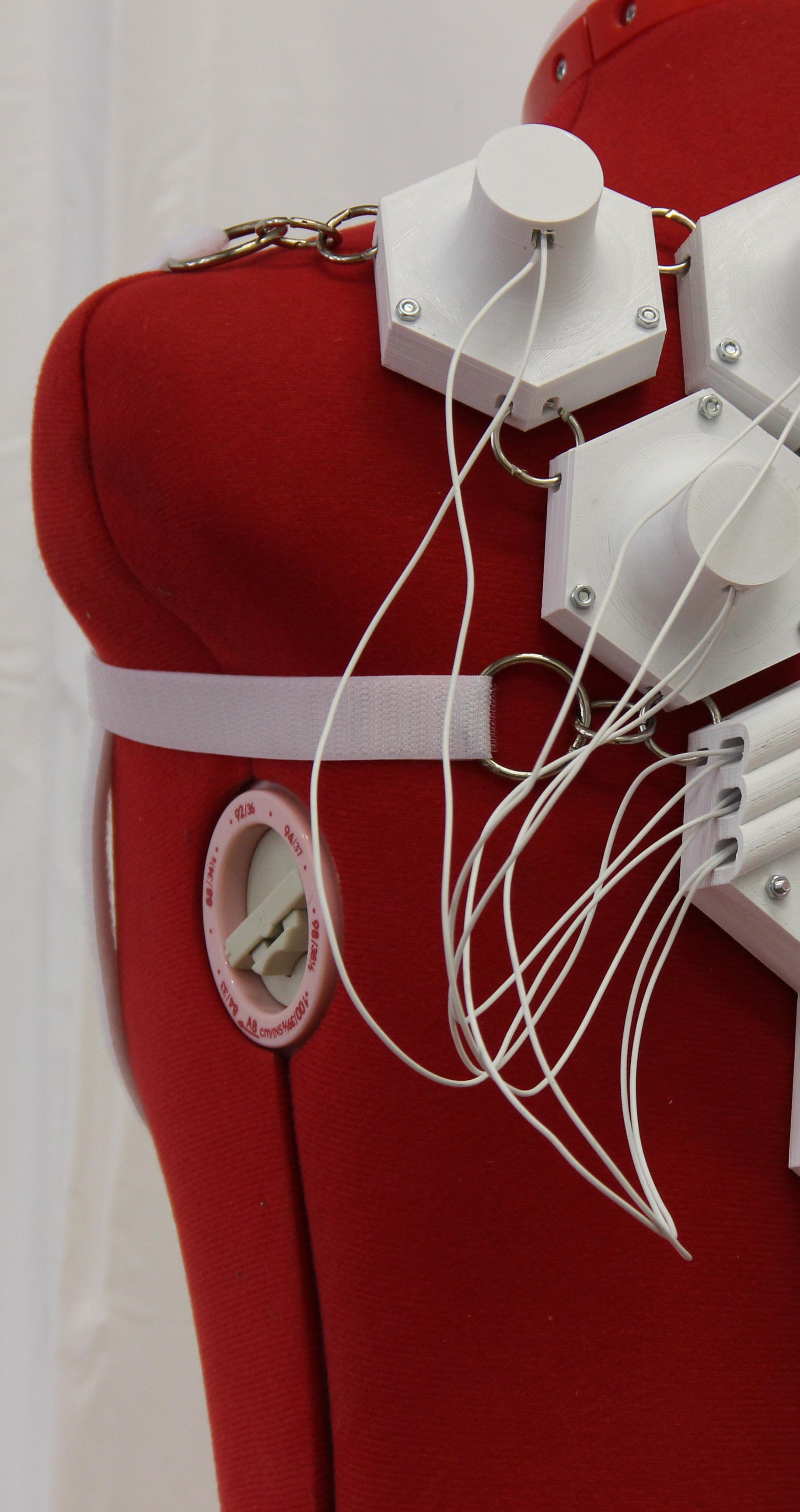
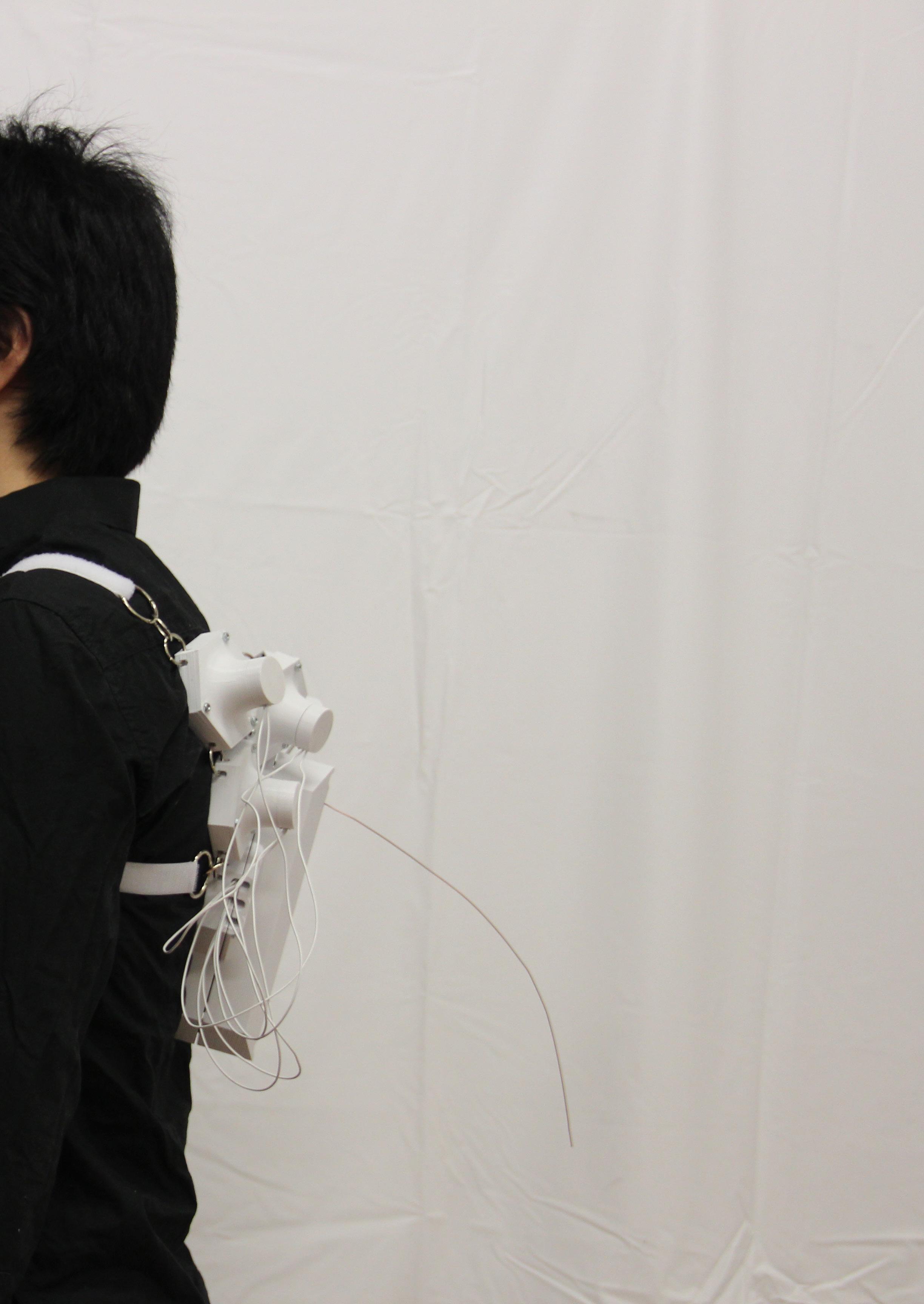
124 View of the back device, showing the velcro stripes on the chest of the user.

125
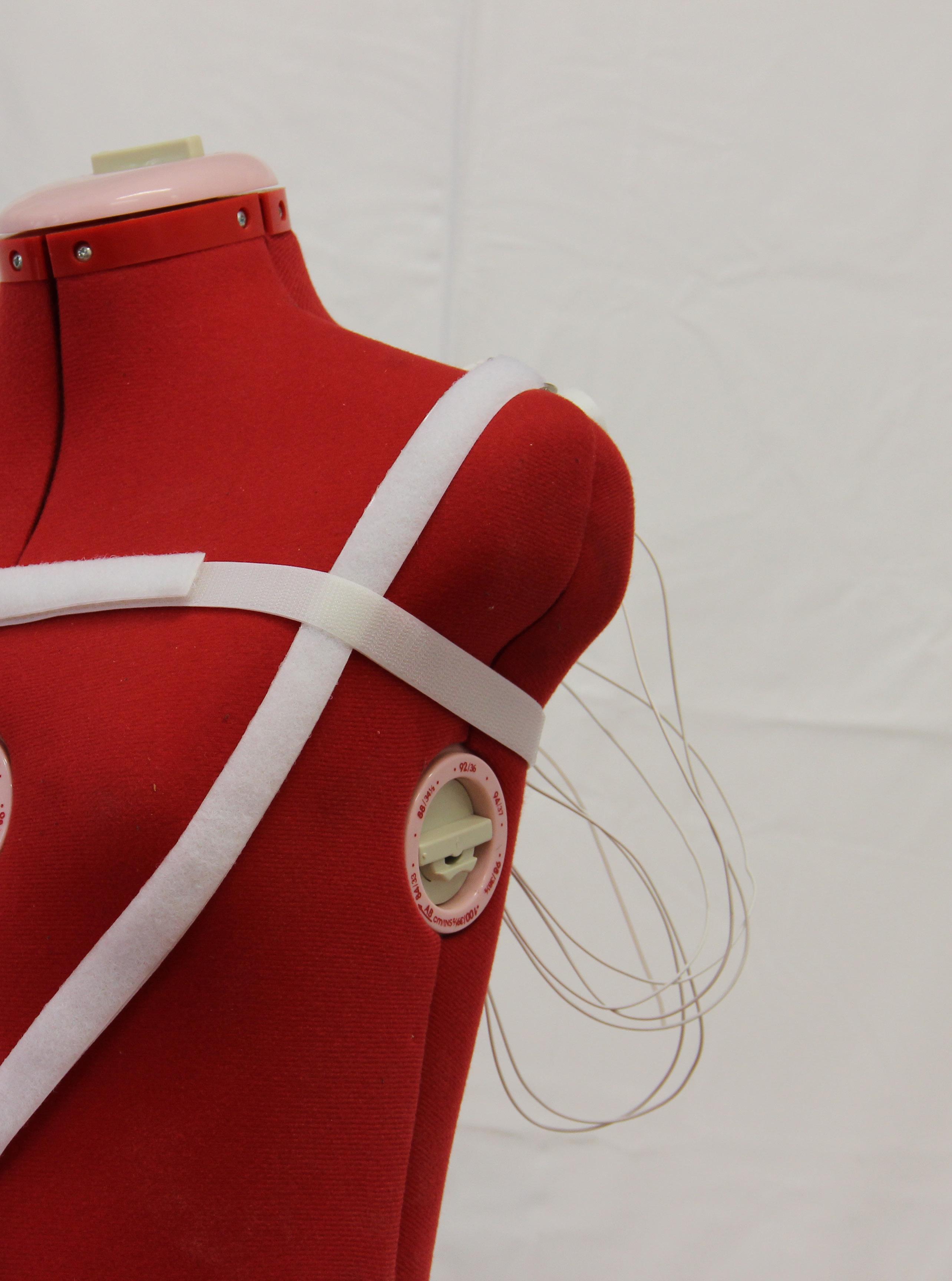
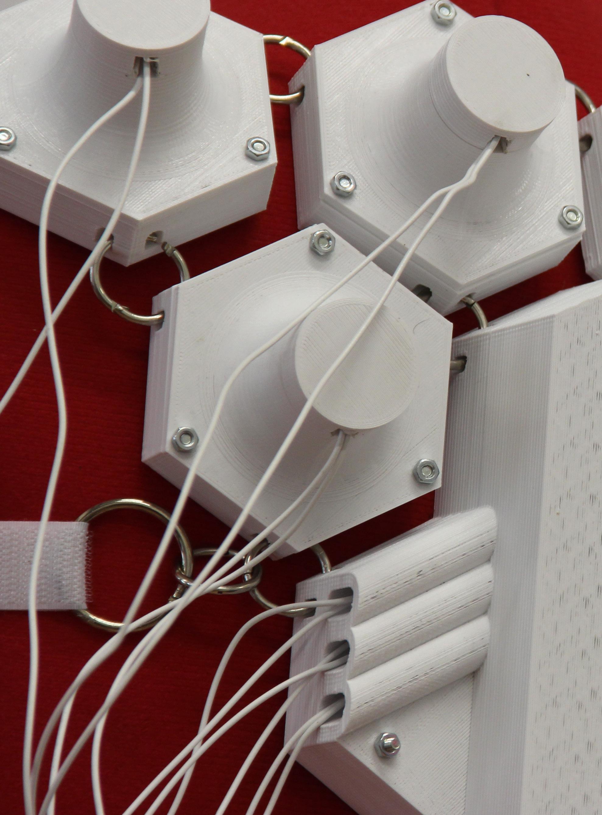
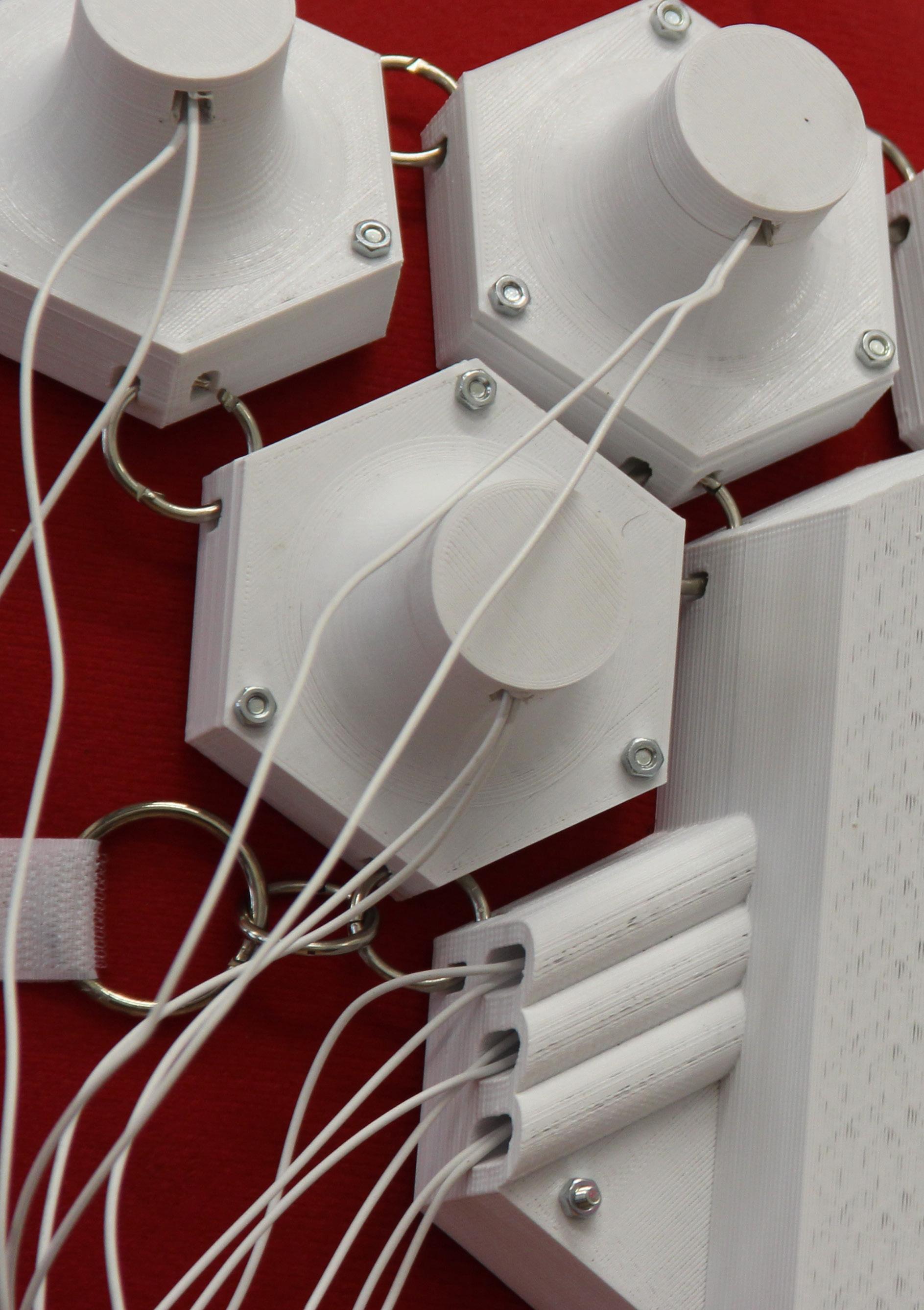
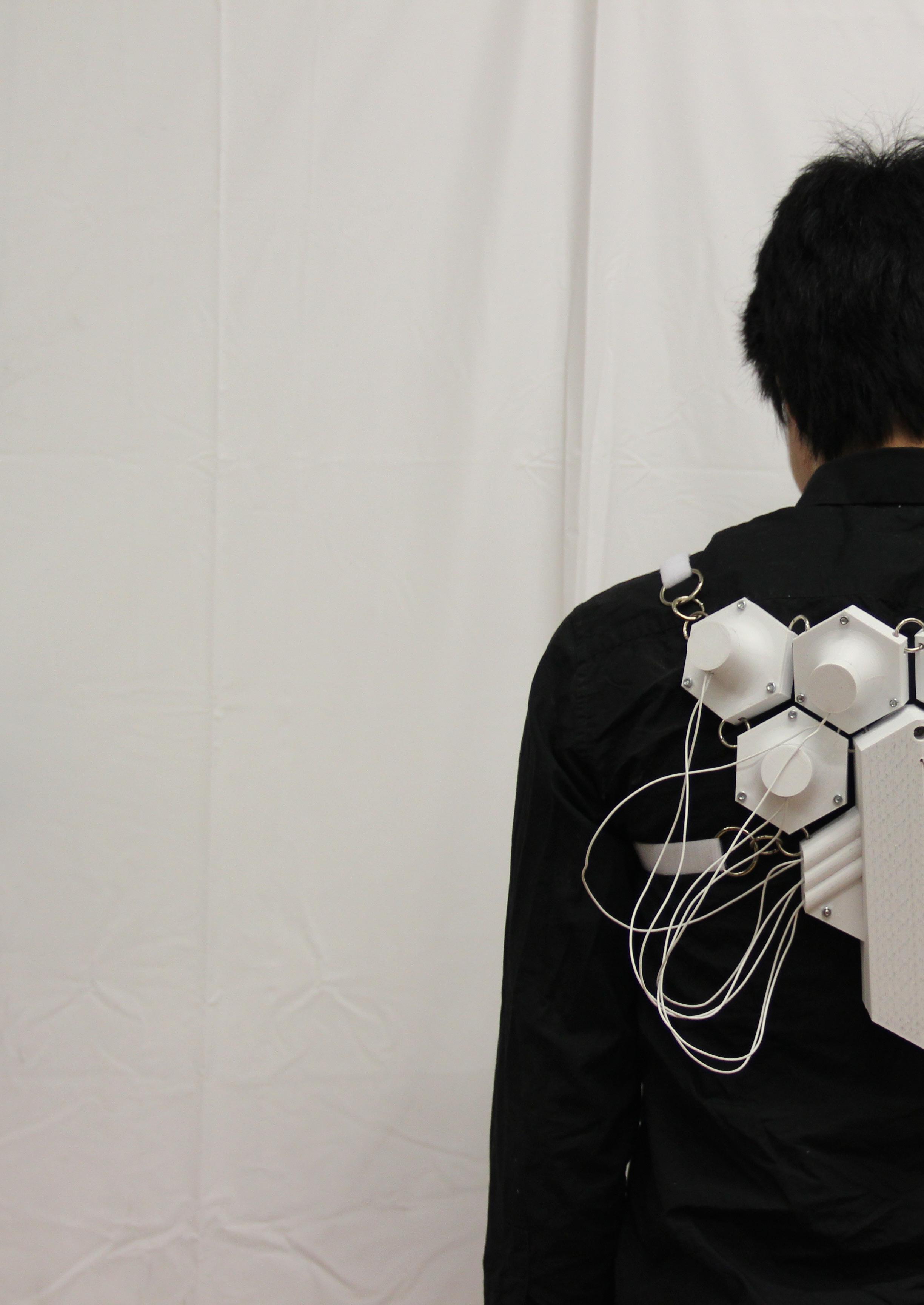
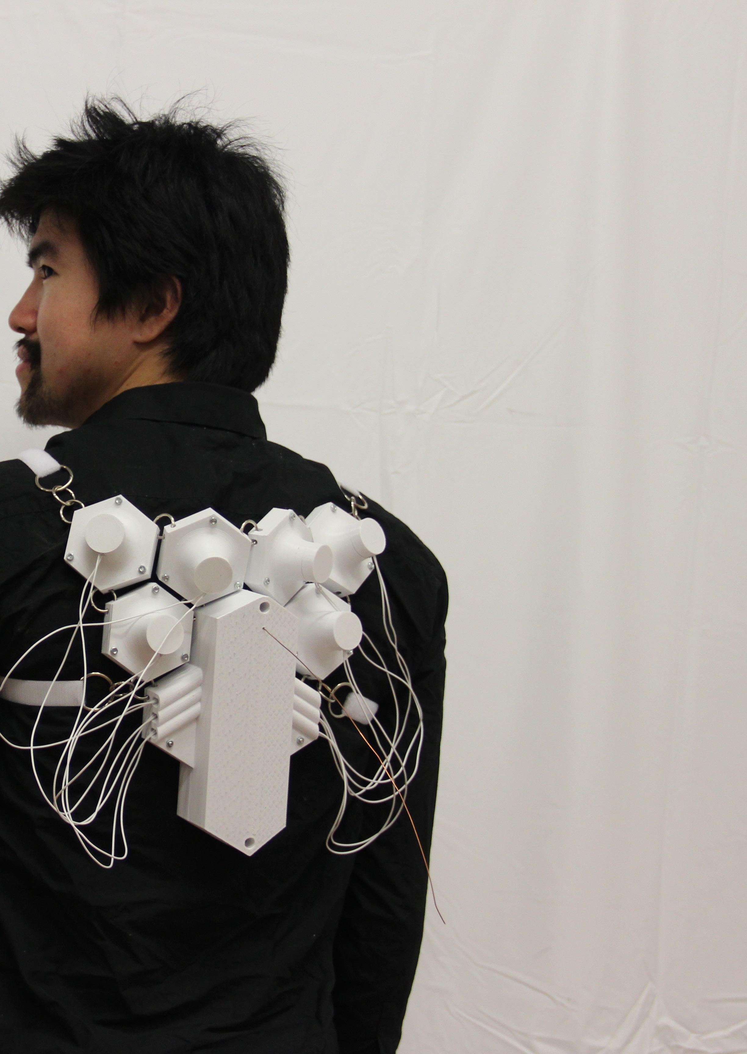
Main view of the back de vice, with the vibrator motors inside all the 3D Prin ted parts, joined with bolts, connected to the main compartment by wires, with the antenna popping out on top.
126
127
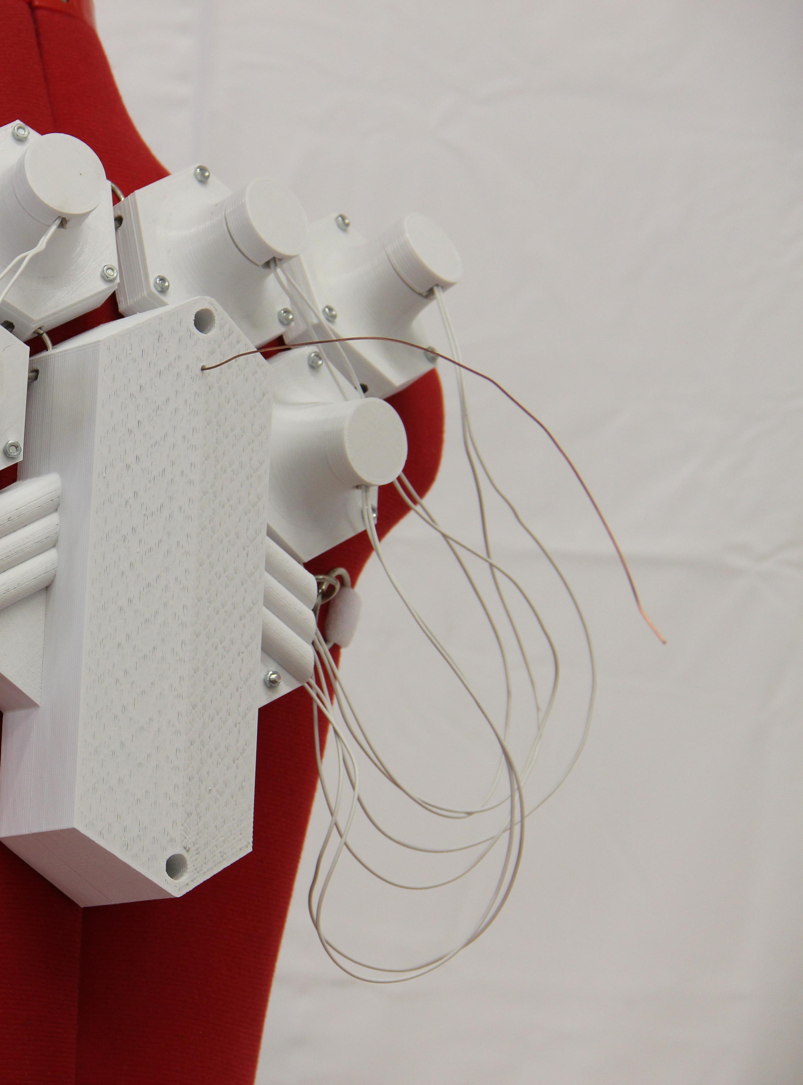
128 View of the back device, with the main compartment open showing the mounted shield on the Arduino UNO, the 7,4V battery feeding the Arduino, 4 1,5V battery feeding the motors and the antenna.

129

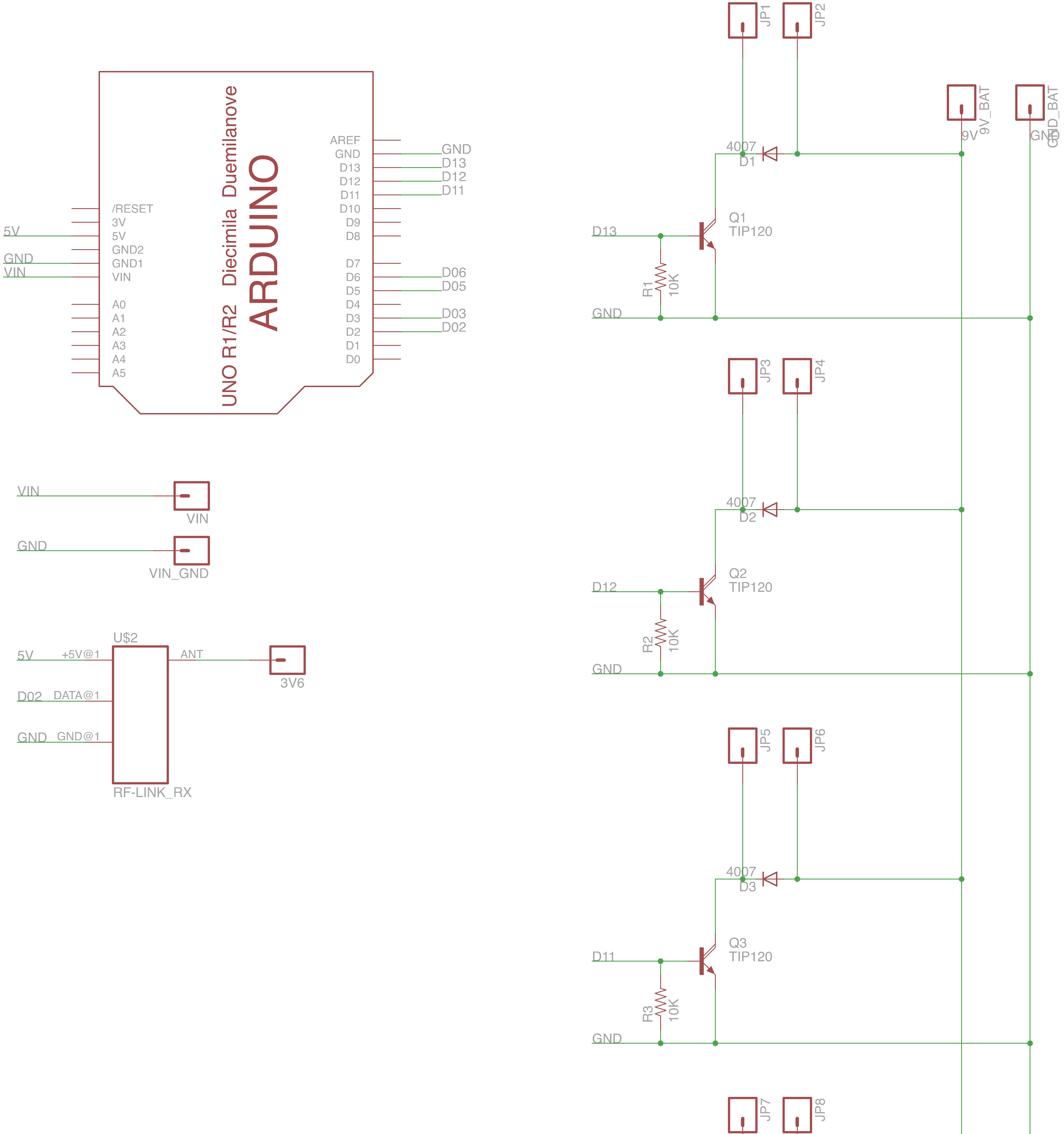
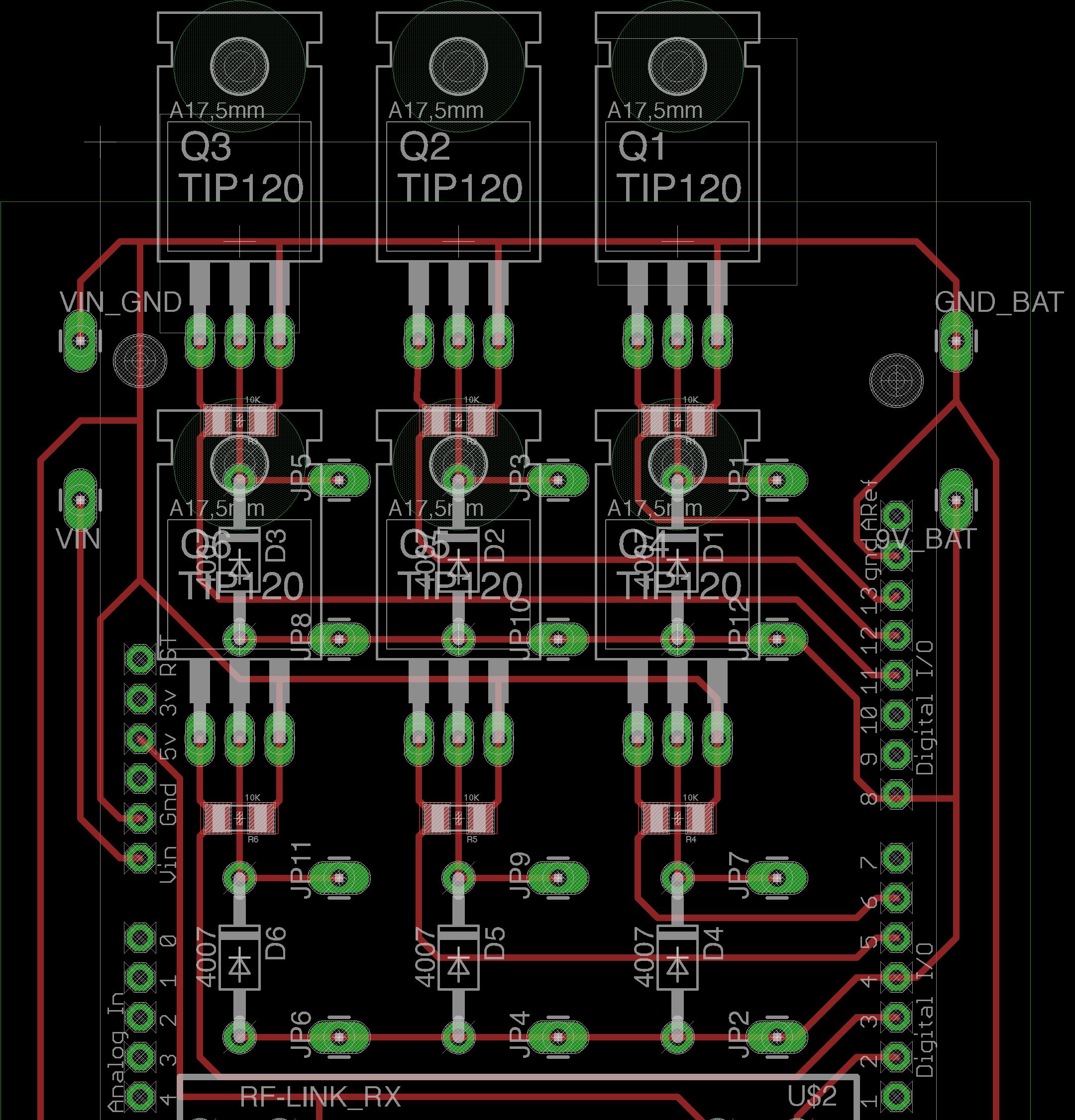
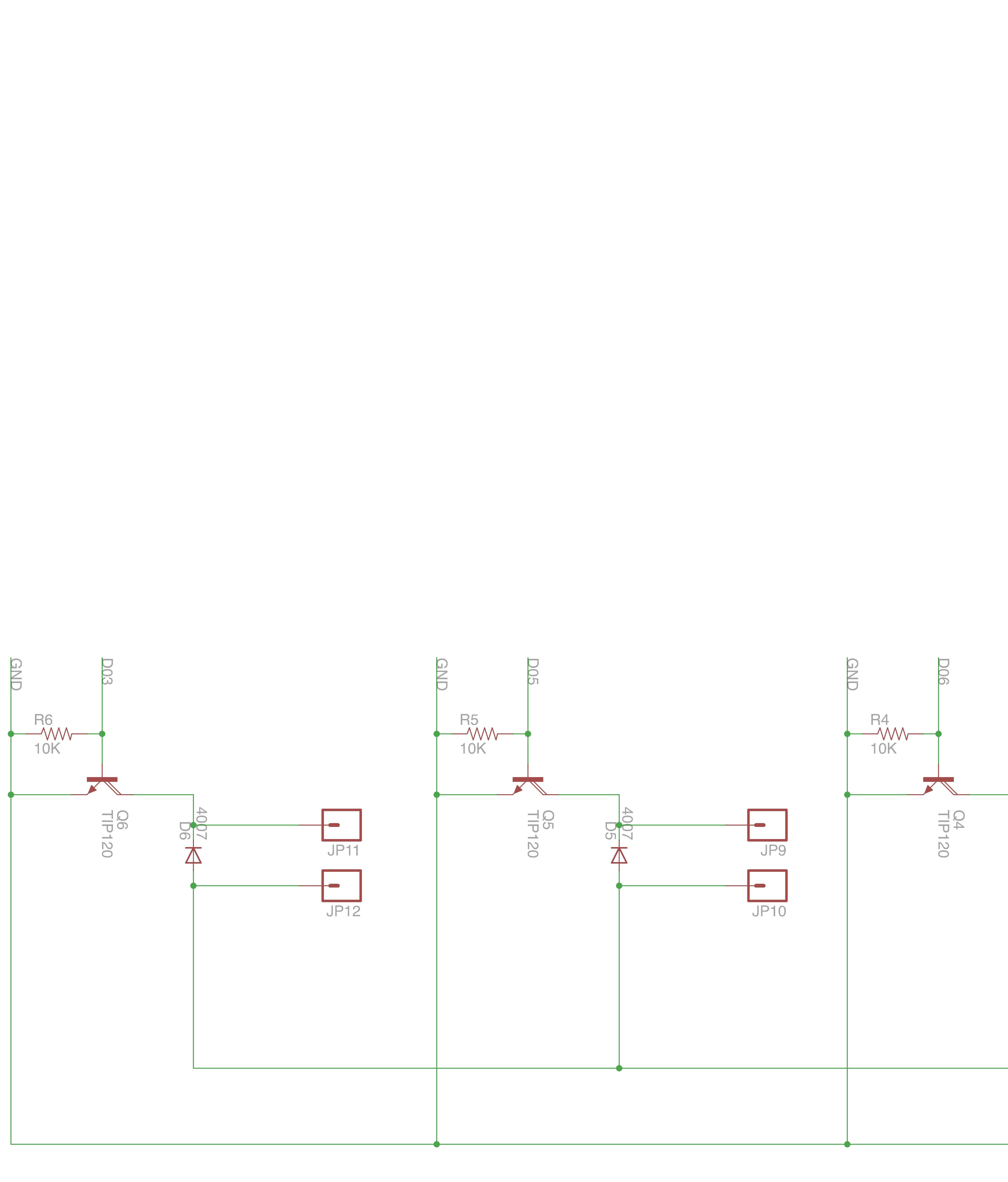
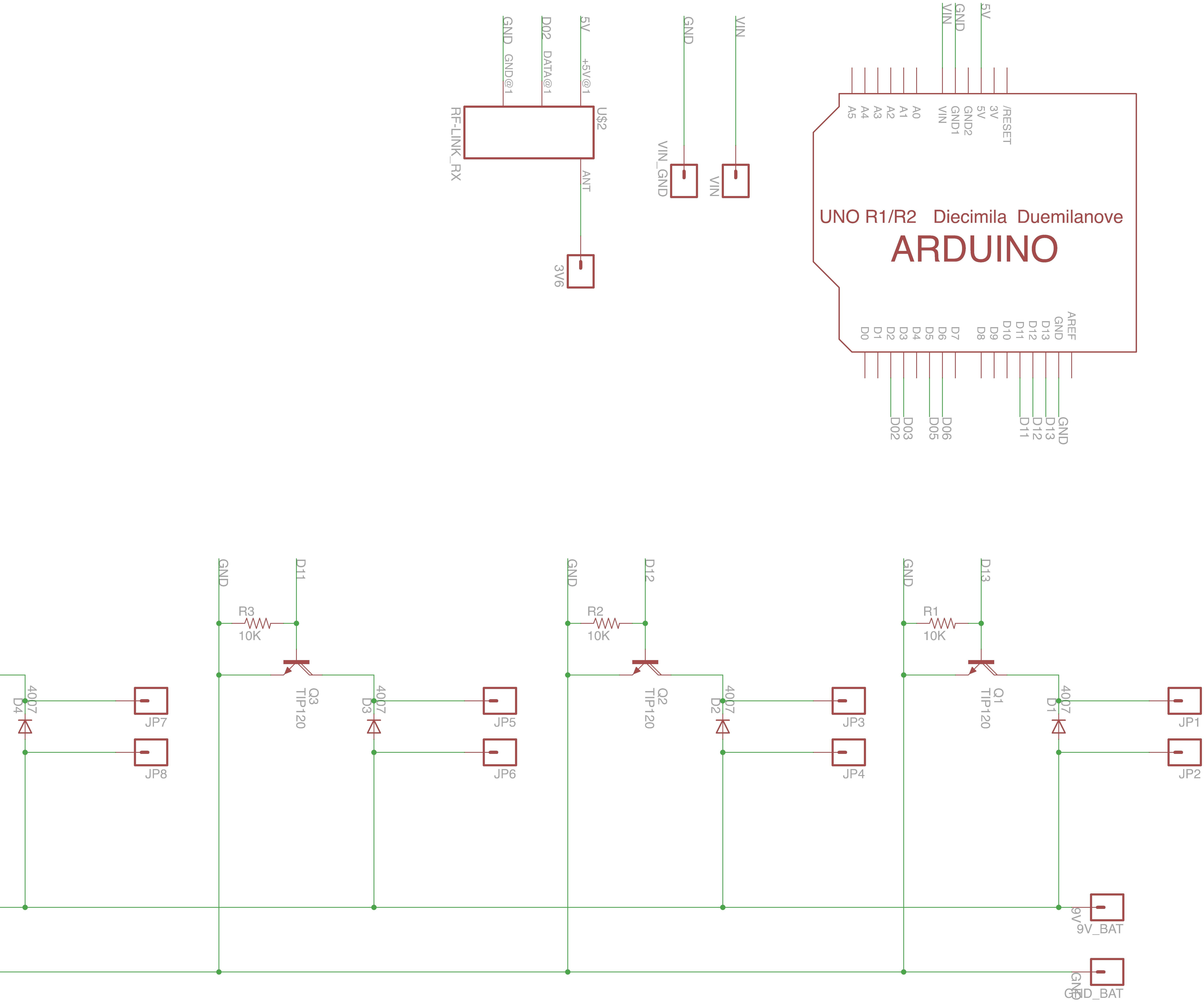
130 Schematic of the Arduino UNO Shield produced.
131
132 Final code of the Arduino UNO. #include <VirtualWire.h> int Sensor1Pin = A0; int Sensor2Pin = A1; int Sensor3Pin = A2; int Sensor4Pin = A3; int Sensor5Pin = A4; int Sensor6Pin = A5; int ledPin = 13; int Sensor1Data; int Sensor2Data; int Sensor3Data; int Sensor4Data; int Sensor5Data; int charSensor6Data;SensorUNOCharMsg[21];// The string that we are going to send trought rf void setup() { Serial.begin(9600); // LED pinMode(ledPin, OUTPUT); // Sensor(s) pinMode(Sensor1Pin, INPUT); pinMode(Sensor2Pin, INPUT); pinMode(Sensor3Pin, INPUT); pinMode(Sensor4Pin, INPUT); pinMode(Sensor5Pin, INPUT); pinMode(Sensor6Pin, INPUT); pinMode(2, INPUT); // button pinMode(13, OUTPUT);//LED for sending // VirtualWire setup vw_setup(2000); // Bits per sec vw_set_tx_pin(3);// Set the Tx pin void} loop() {
133 if (digitalRead(2) == LOW) { digitalWrite(13, true); //Flash status LED to show transmitting // Read and store Sensor Data Sensor1Data = map(analogRead(A0), 710, 450, 0, 255); Sensor2Data = map(analogRead(A1), 710, 450, 0, 255); Sensor3Data = map(analogRead(A2), 710, 450, 0, 255); Sensor4Data = map(analogRead(A3), 0, 850, 0, 255); Sensor5Data = map(analogRead(A4), 0, 850, 0, 255); Sensor6Data = map(analogRead(A5), 0, 850, 0, 255); sor2Data,„%d,%d,%d,%d,%d,%d“,sprintf(SensorUNOCharMsg,Sensor1Data,Sen-Sensor3Data,Sensor4Data,Sensor5Data,Serial.print(„MICROSensor6Data); sending: Serial.println(SensorUNOCharMsg);„); // Turn on a light to show transmitting vw_send((uint8_t *)SensorUNOCharMsg, strlen(SensorUNOCharMsg));vw_wait_tx();//Waituntilthe whole message is gone delay(500); } // Turn off a light after transmission digitalWrite(13, false); }


The project opened a broad range of possibilities for improvement.
Another weak point of the choosen radio frequency components was that radio frequency devices are extremely suitable by noise poluti on caused by eletrostatic that are each day in creasing in our society. The scenario get worst since the project is using so many eletric motors, which by definition generate a extremely big eletromagnetic field. The coil produced by the motors interfere a lot on the radio frequen cy receiver, being very frequent on this project to receive a “dirty data“. The sender part is not affected.
147 Final Conclusion08
The choose for a radio frequency board to send the data from one Arduino to the other had some advantages, a couple of backfires on the project happened. One of them was the delay of information that was intentionaly set from the time that the data is received from the arduino to the moment that it is translated to movent to the DC Motors vibrators. This delay needed to be long enough as one seconc to not over-fload the radio frequency receiver. Altough one second don‘t appear to be a long period, it jeopardize the sense of instant response of the device.
The touch sense demand to develop a langu age in order to comunicate through the touch
148
Theresense. would not be a substitute for a twitter send from a cellphone, or written message tel ling specific information. Other than this, the information sent could be of a specific feeling as love, or hate, or gratitude. The point that could be develop from this pro ject, but demand years of research are the areas that should be excited on the body in order to create this set of desired emotions. This would demand a better research on the phyical part of the motors and also a biological, medical and pysicological team.
The main advantages for using the radio frequency boards was the simpler code that they demand other than the internet one. Also this option was choosen to create an acesible pro ject to be reproduced later in the maker comunity, since it has been choosen a low cost ra dio frequency transmitters and receivers (each ranging fro 8€ to 12€). There are more stable already made shields, but their price range between 40€ to 50€, which would become hard to be freely reproduced.
The ideal way of comunication would be made the connection through internet, which would achieve the desired effect of creating a functi onal new way of comunication other than the cellphones and other common visual devices that are available today. Other than this, one of the main points to emphasize is that altough this project aims to create a new way of comunication, it would ne ver be the same of the existing way of comunications, which are based on the written langua ge and speak language, because those forms of languages are based on different senses, as the vision and hearing sense.
149