STARBUCKS - STUDIO X
Retail + Strategy
PNW Region
Status: Built - Completion Dates Vary Graphite Design Group
Expanded Info:
Client: Starbucks
Duration: 01/23 - Present
Responsibilities:
PA role through all Design Phases.
Test fit through Construction Administration on numerous projects across the Pacific Northwest region.
Overview
Through my time in working for Graphite Design Group, majority of the work has been focused on the retail studio, helping to manage the workflows and BIM strategies to maintain client standards, while also working as a project architect for multiple projects.
Studio X vs. AOR
The partnership between Starbucks and Graphite Design Group has many facets, and has evolved during my time there. Graphite is part of an experimental program called Studio X, which is where partner firms operate in the capacity of a store designer, where you are expected to learn all of the store design guidelines and adhere to their standards, starting from scoping, and continuing the process through the test fit, schematic design, and construction phases of the project all the way through punch walks.
In contrast, Graphite also works in the capacity of a standard AOR, where the design of the store itself is done by a Starbucks internal designer, which is then handed over, and construction documents are created and permitted.
Through my time at Graphite, I have worked both with Studio X, and as an AOR, gaining an understanding of the constraints that are present in both studios, and how to approach them in an efficient and effective way.
2 // Nicholas Place
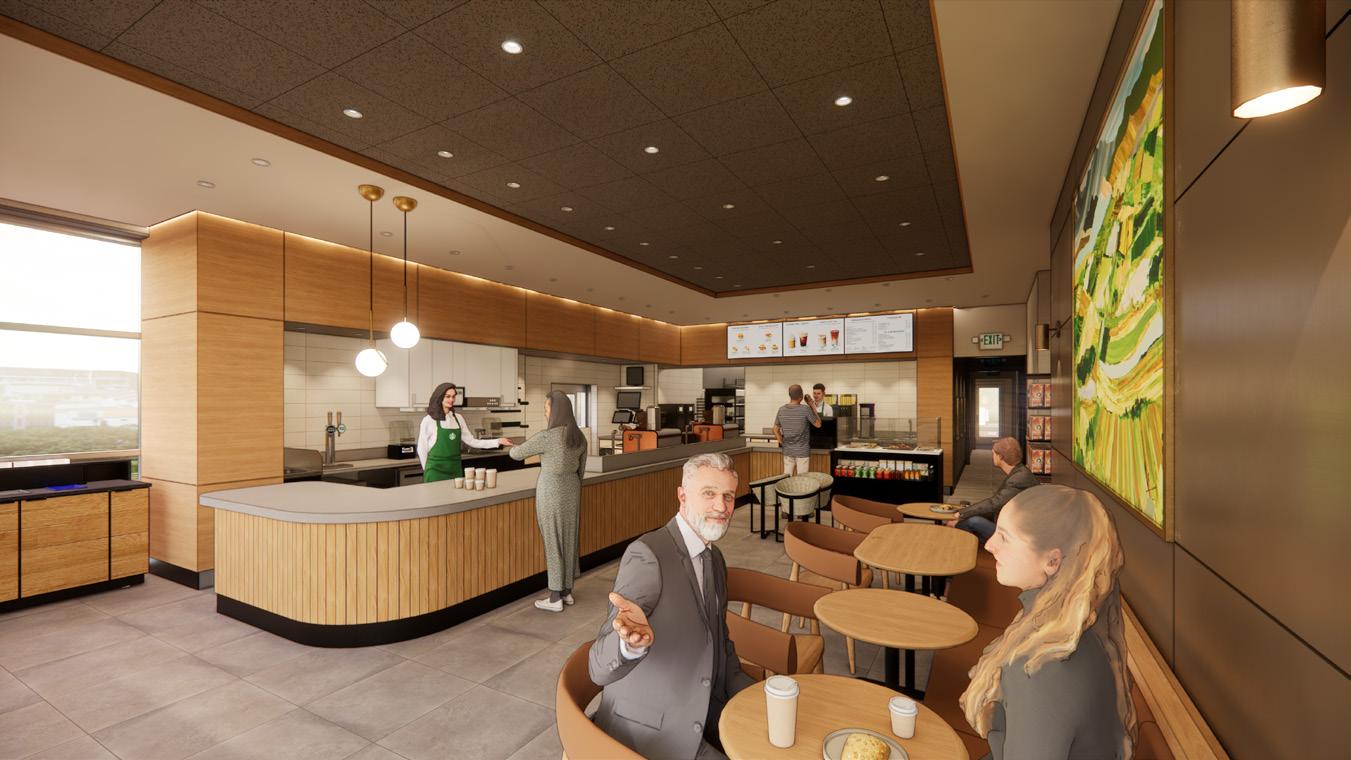
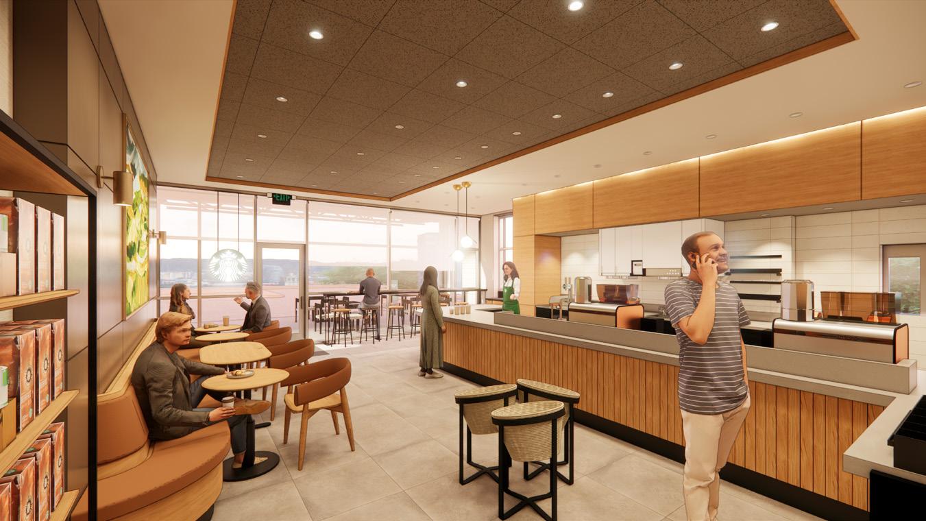
Cafe Entry
Rear Entry
Sit-Here Table
Testing Ground
Due to the repetitive nature of retail work, there is always a degree of repetition that comes with each project. However, while this can also get stale to work with, it presents an opportunity to quickly prototype and test new workflows, offering more effective ways to measure efficiency, which is usually never the case in larger commercial or mixed-use project types.
Through these constant new projects, I was able to build not only a custom template, but also a series of tools that evolved from a simple Dynamo toolkit with custom python nodes, all the way to a fully realized Revit plug-in, created with pyRevit and deployed team-wide.
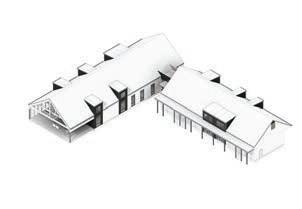
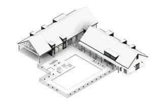
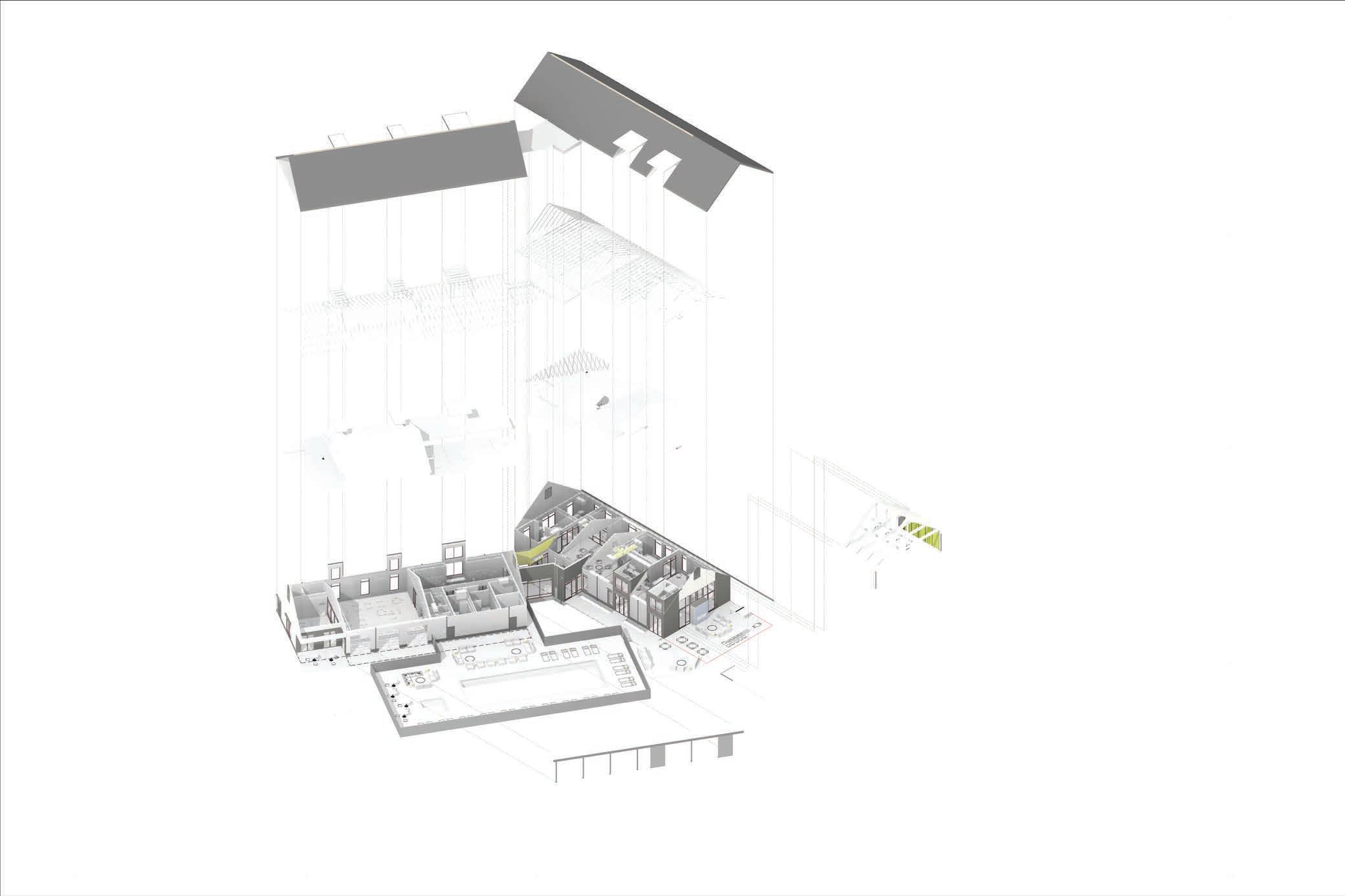
Nicholas Place // 3 PROJECT NAME: PROJECT ADDRESS: STARBUCKS COFFEE COMPANY 2401 UTAH AVENUE SOUTH SEATTLE, WASHINGTON 98026 (206) 318-1575 SHEET : ISSUE DATE: THESE DRAWINGS AND SPECIFICATIONS ARE CONFIDENTIAL AND SHALL REMAIN THE SOLE PROPERTY OF STARBUCKS CORPORATION WHICH IS THE OWNER OF THE COPYRIGHT IN THIS WORK. THEY SHALL NOT BE REPRODUCED (IN WHOLE OR IN PART), SHARED WITH THIRD PARTIES OR USED IN ANY MANNER OR OTHER PROJECTS OR EXTENSIONS TO THIS PROJECT WITHOUT THE PRIOR WRITTEN CONSENT OF STARBUCKS CORPORATION. THESE DRAWINGS AND SPECIFICATIONS ARE INTENDED TO EXPRESS DESIGN INTENT FOR A PROTOTYPICAL STARBUCKS STORE (WHICH IS SUBJECT TO CHANGE AT ANYTIME) AND DO NOT REFLECT ACTUAL SITE CONDITIONS. NEITHER PARTY SHALL HAVE ANY OBLIGATION NOR LIABILITY TO THE OTHER (EXCEPT STATED ABOVE) UNTIL A WRITTEN AGREEMENT IS FULLY EXECUTED BY BOTH PARTIES. PROJECT NUMBER: STORE NUMBER: DESIGN MANAGER: LEWISTON 1325 21ST ST, SUITE A LEWISTON, ID 83501 P-303 03/11/24 09910-079 3354 STUDIO X Typical Retail Model Composition
LEGEND Existing Mechanical Equipment to remain Existing Roof Assembly to remain Existing Mechanical System to remain Existing Structural Framing to remain Ceiling + Soffit Assemblies New Construction Partitions + Finishes New + Relocated Equipment Existing Exterior Wall Assemblies to remain 1 2 3 4 5 6 7 8 1 2 3 4 5 6 7 8 8
Working with Starbucks as a client presents many opportunities, as well as many challenges. There is a plethora of resources available to partner firms, through both their Store Development Resource Center, and their Store Design Catalog. Both of these resources are widely used, both in terms of tracking down the standard store design guidelines that are to be followed for each area of the store, all the way to their catalog, which includes official Starbucks inventory items, each indexed with their own custom Design ID. This information is linked to their BIM library, which is constantly updated, as new items are added and old items are retired on a quarterly (sometimes even sooner) basis. This information is then used to generate order reports for procurement at the end of the construction document phase of the project. Due to this dynamic library, keeping up with the changes can prove to be difficult.
In addition to their catalog for procurement, their BIM standards are also updated on a quarterly basis. However, in an effort to make the template user friendly to those unfamiliar with the Revit environment, numerous smart features are not taken advantage of, creating a lot of unnecessary work that is expected to be done manually. In response to this, I have developed a custom template using Starbucks standards, providing enhancements to the base template, accommodating their standard phasing requirements and scheduling in a lightweight way, ensuring that merging the custom elements are easily integrated with the next version of the template.
4 // Nicholas Place
Process + Complexities
Site Survey Test Fit MEP Pre-Design Package Structural Pre-Design Package HVAC Upgrade Scoping Store Design Catalog Store Design Guidelines Construction Documents IFC Model Order Report Record Drawing Package Survey Model 3D Capture Walkthrough Custom Template Central File Custom Template Standard Process Due Diligence Pre-Design & Resources Schematic Design Construction Document Kick-off Consultant Coordination Construction Documentation End CA & As-Builts
Automating the process
As mentioned previously, within the standard Starbucks template, there are quite a few areas that do not take advantage of the features available in Revit, making typical tasks quite cumbersome, which in turn is a detriment to the efficiency of team members, as well as the overall profitability of the project.
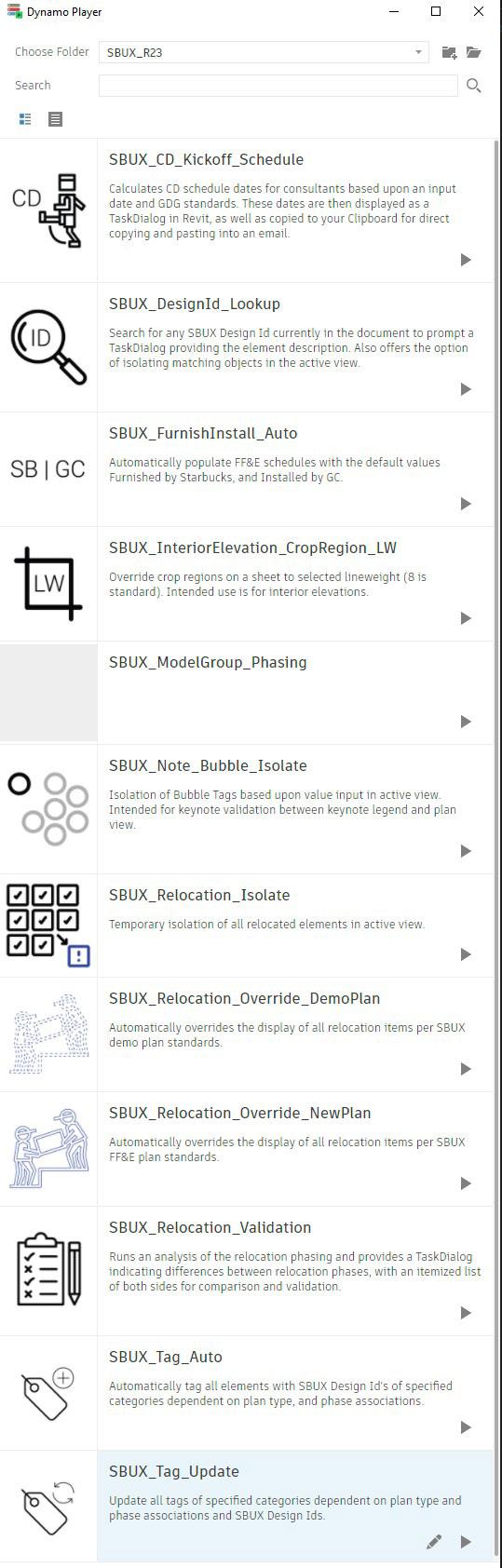
After a brief introduction to the Starbucks ecosystem, I started creating a custom toolkit to address Starbucks specific issues. This toolkit was created using Dynamo, and all run through the Dynamo Player for ease of use by the team once deployed. The Dynamo toolkit was created using custom python nodes, which was necessary for manipulation of the Starbucks custom shared parameters.
Additionally, instructional documentation was created for internal use to help assist team members understand how the tools are meant to be used and how to get the most out of their utilization.
Nicholas Place // 5
Dynamo Toolkit
Tool Evolution
As work on the toolkit progressed at a steady pace, the number of tools was increasing quickly, as was the need for easier deployment. In order to address these concerns, I transitioned the Dynamo toolkit into a fully functional Revit plug-in, using pyRevit. From there, I added a large range of tools, ranging from standard links, all the way to phase transferring between constantly updating templates.
Sections Expanded
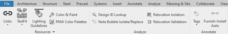
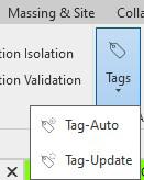
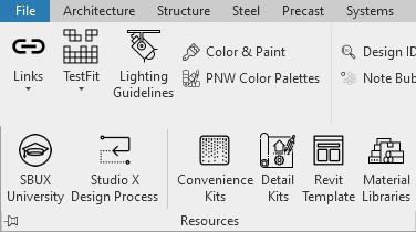
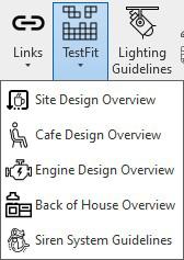
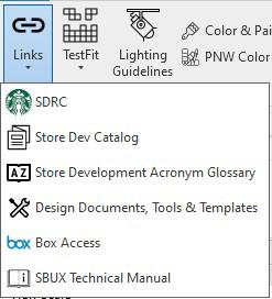
The composition of the SBUX toolbar is broken into different areas, all addressing different sections of the model and project environment. The first section is plainly just various resources that are often difficult to track down, whether they are stored locally, or online via the Starbucks portal. Additionally, there are links to local resources created and managed by Graphite, whether it is asset kits provided by Starbucks, or educational information created in-house for lunch + learns, or general processes that have been developed over time.
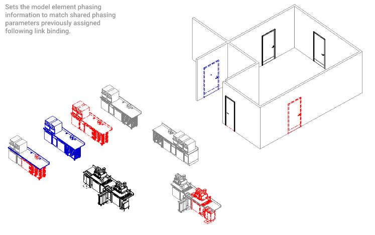
Additional tools have been added for analysis, specifically to deal with parsing Starbucks specific Design IDs within the document, and tools for analyzing and validating that phasing is being assigned correctly.
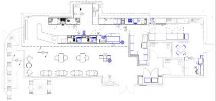
Additional tags have been added for custom annotation for Starbucks specific conditions. These tools take into account only Starbucks specific families of certain categories that are dependent by view, and assigns the appropriate tag by separate shared parameters as well as assigned phase.
6 // Nicholas Place
1 2
3 4
pySBUX Plug-In
1) Helpful links to Starbucks Documents + Portals
2) Links to Store Design Guidelines
3) Links to local SBUX Resources + Libraries saved on the Graphite Server
4) Tools for custom auto-tagging
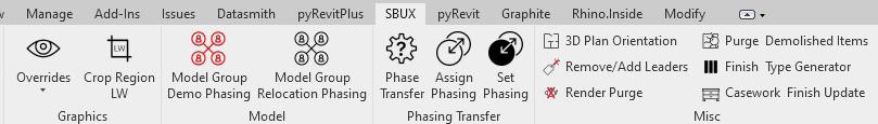
Sections Continued
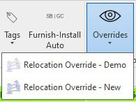
Graphic tools were added to help apply, and reset standard overrides typically applied to elements based upon phasing. An additional tool was also created to update the crop region of interior elevations, to eliminate the inefficient existing workflow of using filled regions as boundaries.
Unfortunately, one of the standard Starbucks standards in their library is the wide implementation of model groups instead of nested families. Due to this, when processing elements and assigning proper phasing, this creates a laborious process of manually grabbing all of the members of model groups and assigning the appropriate phases. To help address this, tools have been created to auto-assign all group members in all selected model groups to align with client standards.
As more projects kept coming, we ran into issues with our template, and ensuring that projects were using the “latest and greatest” whenever the CD phase commenced. In order to do this, we developed a process of phase transferring into new templates at different project phases. This process is currently aimed at inserting the active model into a new template at the test fit/ schematic design phase start. Due to how long the schematic design process takes at Starbucks, there is usually a quarterly release update by the time we start construction documentation, so models are also inserted into a fresh template prior to CD Kick-off.
Finally, there is a section of miscellaneous tools meant help speed up common processes in standard documentation, purging existing as-built models not created from a site survey, as well as render aids. Additionally there are tools for managing the material libraries through the creation of finish assemblies, following consistent naming conventions and thicknesses.
Nicholas Place // 7 5
5) Custom Phase Overrides
Starbucks Standard Phases
Starbucks Relocation Phasing
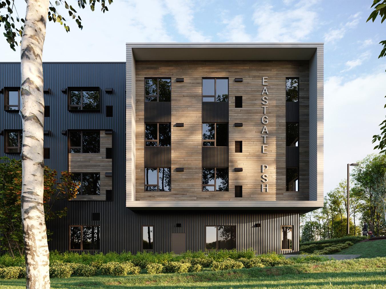
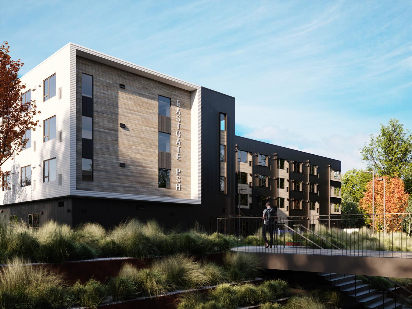
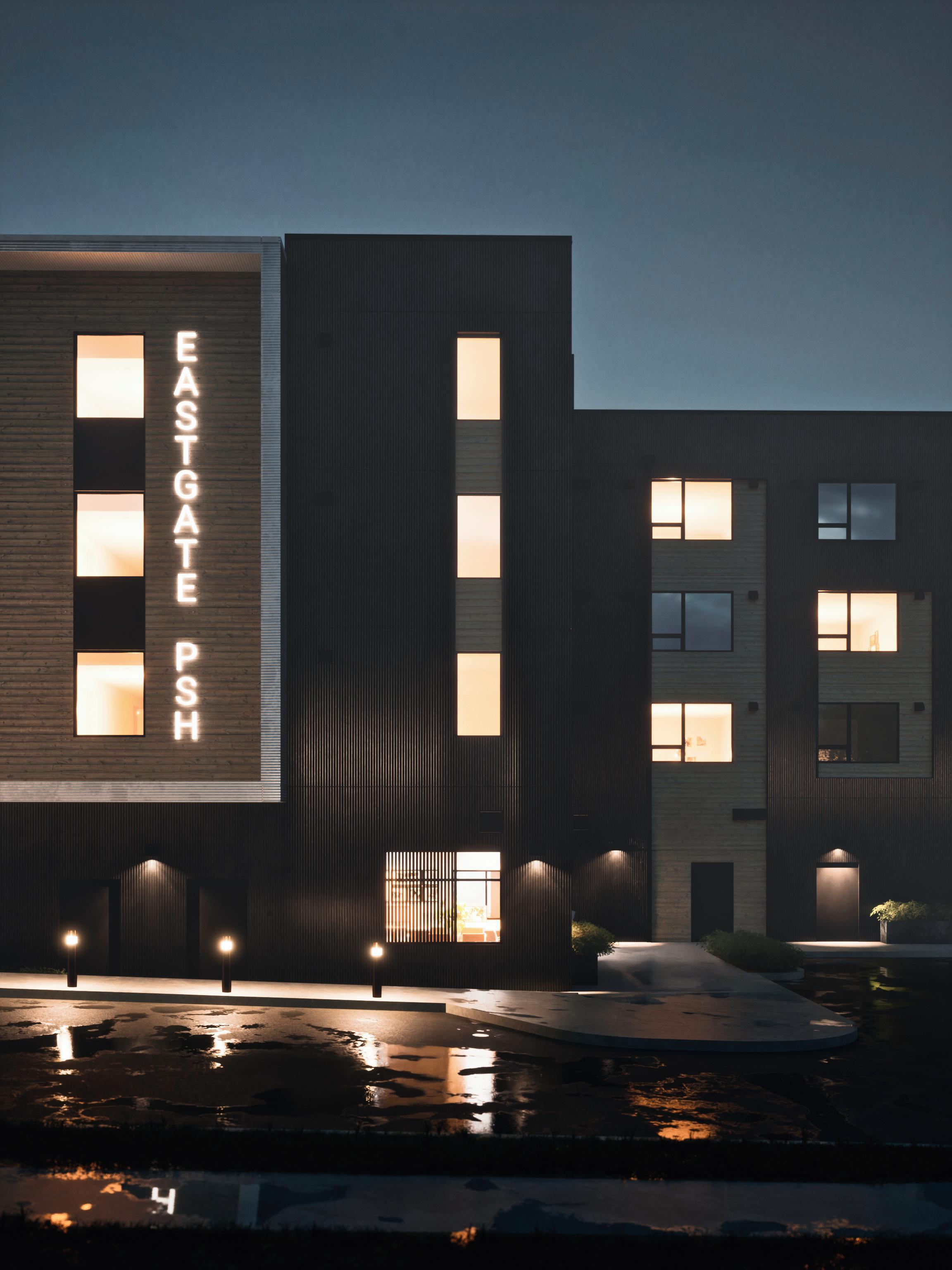
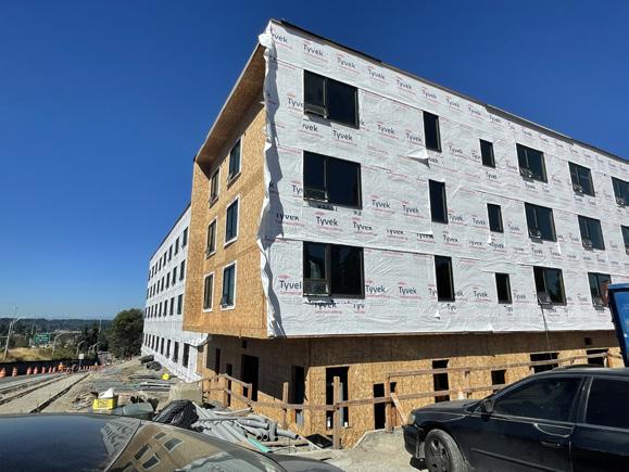
EASTGATE PSH
Permanent Supportive Housing
Bellevue, Washington
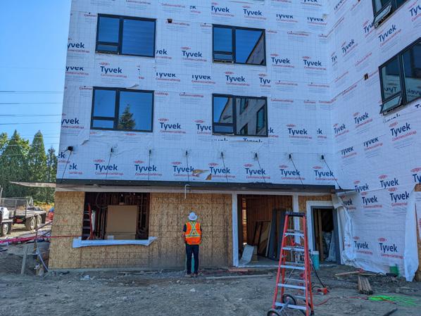
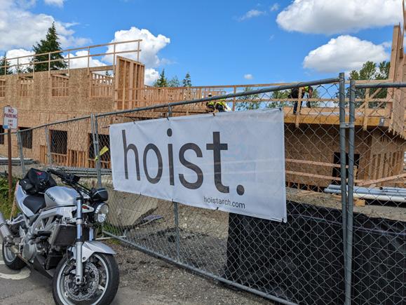
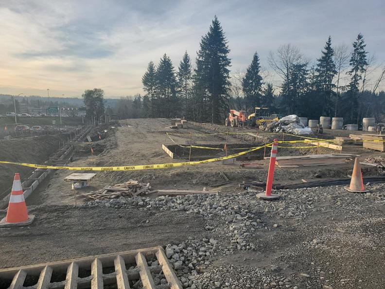
Status: Under Construction hoist.
Expanded Info:
Client: Plymouth Housing
Cost: ± $12.8 M
GSF: ± 54,000
Duration: 08/20 - Present
Responsibilities:
Project Lead through all Design Phases.
Schematic Design through Construction Administration.
Campus of Change
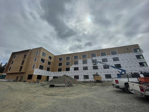
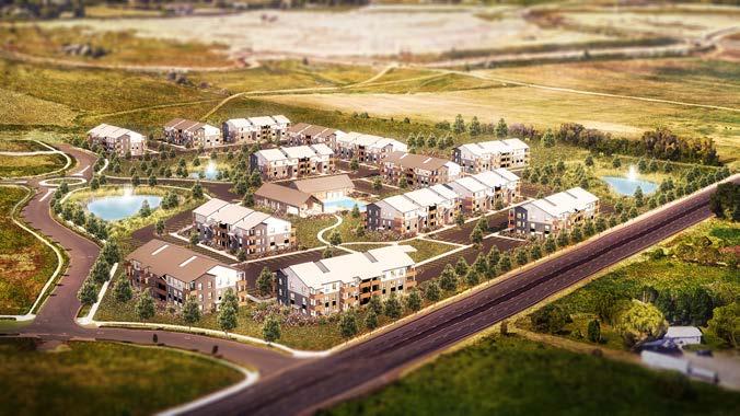
Located just off of I-90 in Bellevue, WA, Eastgate PSH is part of a master plan called “The Eastgate Housing Campus.” The campus consists of 3 unique phases; Phase I is a large residential apartment complex on the site’s lower shelf. Phase II is wholly a permanent homeless shelter (the first in Bellevue), following with Phase III, which consists of Eastgate PSH.
A New Model
This entire project is rather controversial within the city of Bellevue, stemming from this project containing the first permanent facilities within the city that cater to the homeless and a support structure for those leaving homelessness.
Plainly put, PSH is an acronym for Permanent Supportive Housing. The goal for these facilities are to offer formerly homeless citizens the opportunity to have a safe, affordable place to live while they transition back into society. With this, the entire upper shelf is comprised of a partnership between CFH (Congregations for the Homeless) and Plymouth Housing to offer this brand new arm of support to a community in need.
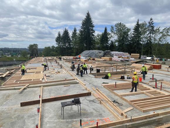
Pandemic Playbook + Concrete Strikes
Throughout the life of this project, there have been many issues and delays caused by both the Covid-19 Pandemic, as well as the months-long concrete strike that hit King County causing the project to be delayed for months on end. Coupled with the exponential cost of price escalations across the board, the need for a robust VE exercise became apparent, and successfully brought the project cost back down to reality.
8 //
Nicholas Place
N
Shelter View
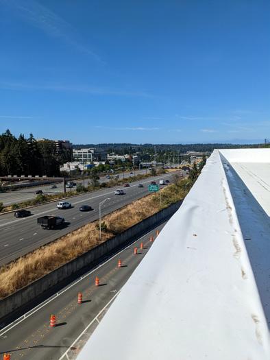
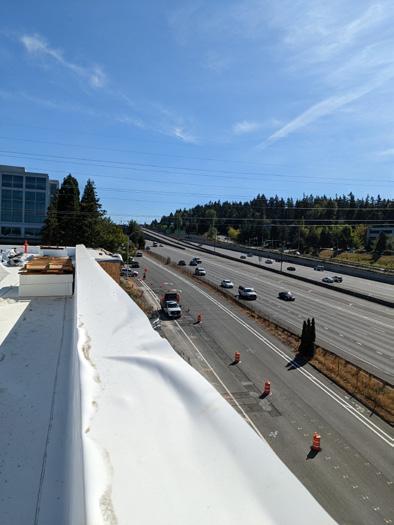
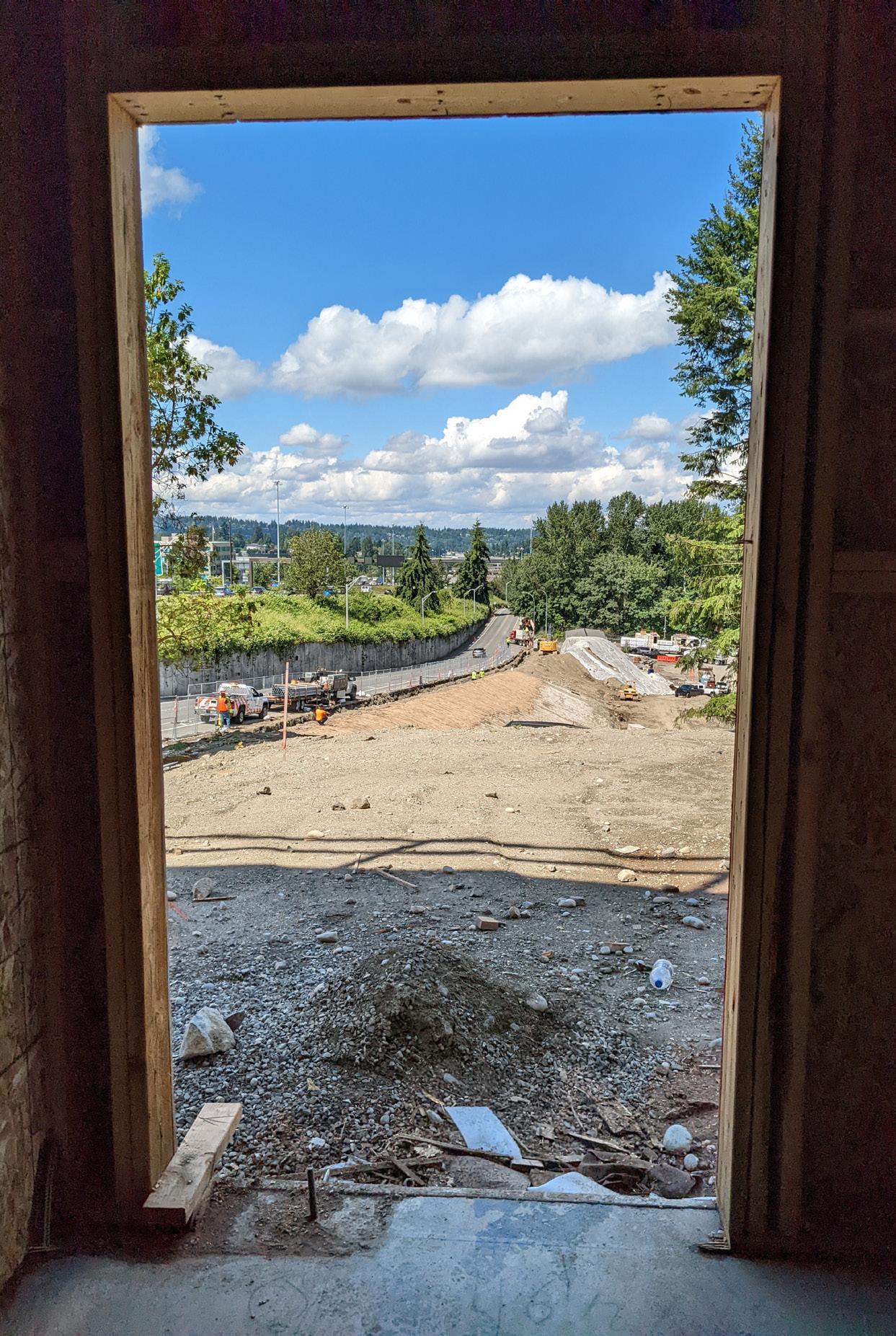
Highway View
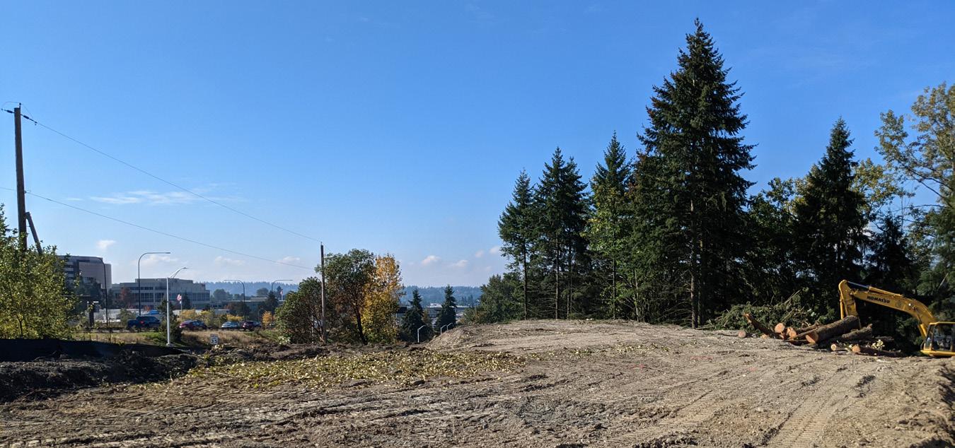
The Beginning.
credit: notion workshop
credit: notion workshop
The prominent location of the project site is situated right on the high-traffic location of I-90, right at the connection between Bellevue and the Seattle Metro Area.
Nicholas Place // 9 Vertical Circulation Cores Campus Master Plan N SE EASTGATE WAY S STGATE WAY VAN PHASE I POLARIS (360 UNITS) PHASE III HHA (95 UNITS) PHASE II CFH 100 BEDS EARLY LEARNING CENTER ENTRY LEASING LOBBY ENTRY HHA BUILDING CFH BUILDING MAIN ENTRY 0 3 8 3 4 W 1 4 0 N1°18'59"E 98.00' N83°20'35"W 705.06' N521248W 11813 N88 3 04 W 05 1 N 1 1 8 3 2 4 N85°46'25"W 209.10' N4°13'35"E 20.00' N85°46'25"W 150.00' N4°13'35"E 20.00' N4°13'35"E 10.00' N85°46'25"W 531.99' 31 W 280 N85°46'24.88"W 115.823' S 8 33 6 2 W 136 765 N 2 6 W 1 4 3 N5°20'50.97"E 23.606' SCALE: 1" = 40'-0" ADDRESSING SITE PLAN POLARIS UNIT MATRIX - MDP UNIT TYPE QTY UNIT A1 126 12 UNIT A6 139 UNIT 2 BEDROOM UNIT B1 37 UNIT B2 71 CFH UNIT MATRIX UNIT TYPE QTY UNIT (BEDS) 100 HHA UNIT MATRIX UNIT TYPE QTY Exploded Iso Location
Roof Assemblies Elevator Overrun Solar Array RTU + Screening Horizontal/ Vertical Interior + Demising Assemblies Exterior Wall + Skin Assemblies Amenity Patio Outlook Bent Plate Canopy @ Entry Exterior Fenestration Highway Adjacencies East West PHASE III PSH (95 UNITS) PHASE II CFH(100 BEDS) PHASE I POLARIS (360 UNITS)
10 // Nicholas Place PROGRAM LEGEND Control Room Community Room Computer Room Kitchen Office Clinic Clinic Office Staff RR Server Bed Bug DAS Mechanical Electrical Storage Unit Laundry Refuse Elec/IDF 1 2 3 4 5 6 7 8 9 10 11 12 13 14 15 16 17 18 19 1 2 3 4 11 12 14 5 5 5 6 5 7 5 5 8 9 10 13 9 L1 Plan FD FD FD FD FD FD FD FD FD 1/32" = 1'-0" PLAN 0' 16'32' 8' N FD FD FD FD FD FD FD FD FD FD FD FD FD FD 1/32" = 1'-0" FLOOR PLAN 0' 16'32' 8' N L2-L4 Plan (Typ) FD FD FD FD FD FD FD FD FD FD FD FD FD FD 1/32" = 1'-0" FLOOR PLAN 0' 16'32' 8' N FD FD FD FD FD FD FD FD FD FD FD FD FD FD 1/32" = 1'-0" FLOOR PLAN 0' 16'32' 8' N Roof Plan 1/32" = 1'-0" PLAN 0' 16'32' 8' N FD FD FD FD FD FD FD FD FD FD FD FD FD FD 1/32" = 1'-0" FLOOR PLAN 0' 16'32' 8' N 15 15 15 18 16 (TYP) 16 (TYP) 17 19 15 18
Upper Shelf Development
In the spirit of interconnectivity, the two phases on the upper shelf aim to reflect each other through both design intention, as well as the functionality of the shared expression between the shelter and the PSH building.
Nicholas Place // 11
View From CFH Shelter
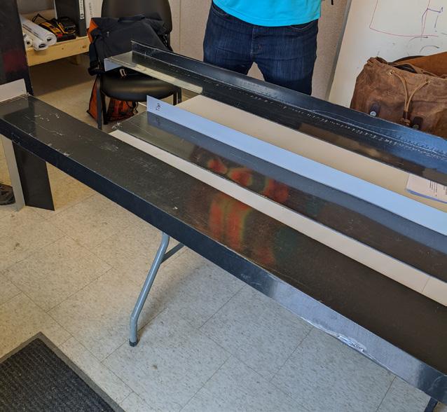
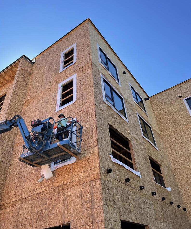
Window Shroud On-Site Assembly
One prominent design decision that was heavily featured on the project was the use of window shrouds, providing a prominent sense of depth on an otherwise flat facade by providing defined transitions between openings, as well as similar fabrications at notable siding transitions. Due to cost escalations already having an impact on the project, a method for fabricating these shrouds was developed from a multiple piece assembly in lieu of a single-piece fabrication.
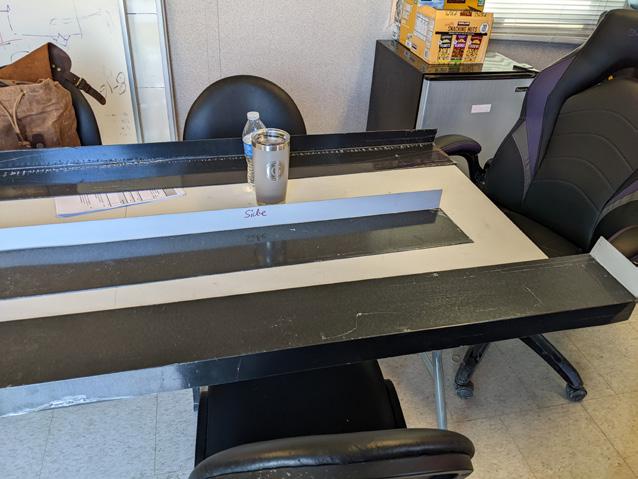
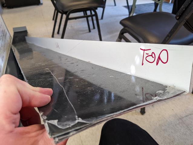
Window Shroud Fabrication Diagrams Simplified Sequencing Abstraction Window Shroud On-Site Assembly 12 // Nicholas Place PERSCHEDULE PER SCHEDULE 9300 ° 8700° 3° TYP 2" 6" 5 7/8" PER SCHEDULE 5' - 6" A B C 5 7/8" 6" 2" 2" 2" PER SCHEDULE 7' - 6" 3 00 3 00 A - TOP B - SIDES (L/R) C - BOTTOM 2" 6" 5 7/8" PER SCHEDULE 7' - 6" WELD OR RIVET BENT TABS TO SIDE PIECES. TYP EA. END. POWDERCOAT BLACK, TYP. DN UP DN UP LEGEND BEND DIRECTION CREASE/BEND DN DN UP UP *MIRROR BENDS @ OPP.SIDE DN DN UP UP 3.00° TYP EA. SIDE 3.00° TYP EA. SIDE 3.00° TYP EA. SIDE 3.00° TYP EA. SIDE 2" 2" PROJECT #: A.S.I. #: REF. BUILDING: REF. SHEET: DRAWN: DATE: ARCHITECTS SUPPLEMENTAL INSTRUCTIONS EASTGATE PSH 13638 SE EASTGATE WAY BELLEVUE WA, 98005 2009 SK-01 hoist. 01/26/22 WINDOW SHROUD
LEGEND Exterior Wall Window Window Shroud Transition Flashing Exhaust Hood Termination Siding Conductor Head/Downspout Building Signage Bent Plate Awning 1 2 3 4 5 6 7 8 9 2 4 5 6 8 1 9 2 3 4 5 6 7
Kalwall 2-3/4” open canopy system w/ type A face sheet @ wall + roof.
HSS 5x5x3/16 frame per structural w/ antigraffiti coating
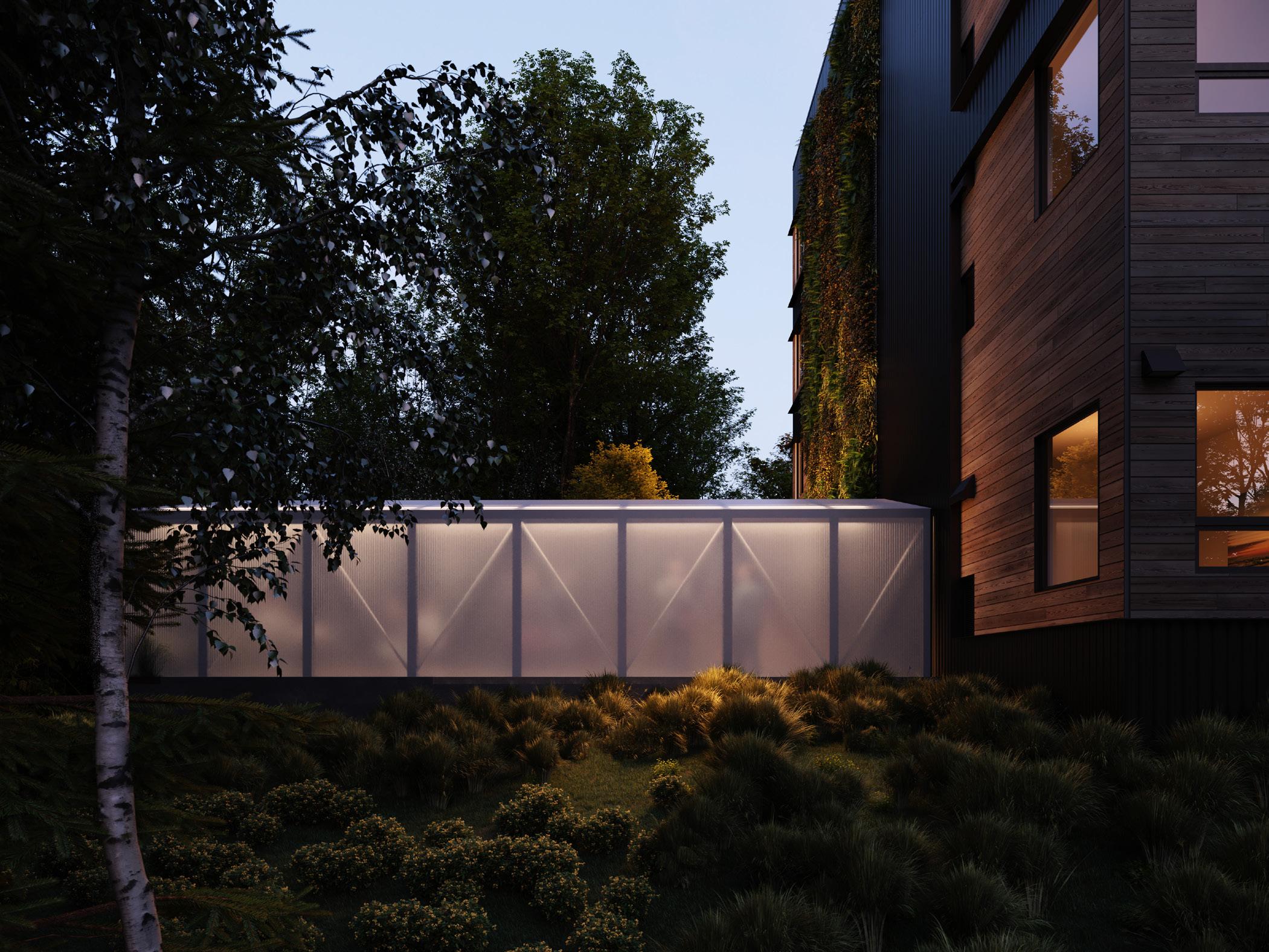
7’H perimeter fence 12MM Plazcarb (Transparent Finish) Polycarbonate Panels @ exterior side of fence barrier on west side of amenity area
Amenity Shelter
Another featured design element of the project is the amenity shelter located in the west amenity area directly adjacent to the building’s west corridor exit. Going through many design iterations, eventually the final design of the structure consisted of translucent panels along the south wall and roof covering, providing the required acoustic barrier while also remaining visually striking from the street.
Amenity Shelter | Night
Nicholas Place // 13
Amenity Shelter | Iso
credit: notion workshop
LEVEL 1 230' - 0"
LEVEL 2 243' - 0"
LEVEL 3 253' - 0"
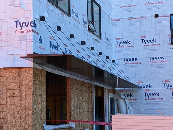
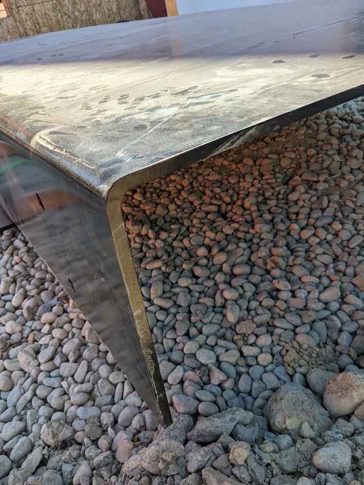
At the main building entry, a prominent feature to the design is the bent plate steel canopy located at the main entry knuckle. The idea being to appear thin and light, hovering above the entrance as a single flat plane, extending past the corner of the building, only visibly held back by thin cables.
The canopy itself was actually fabricated in two pieces with some skillfull joinery onsite to create the assembly as a solid piece.
14 // Nicholas Place
Bent Steel Plate Canopy
Bent Plate Canopy
37 ' -9 " 3 " GAP 5'- 0" 1'0" 5 ' -0 " 5 ' -0 " 5 ' -0 " 5 ' -0 " 5 ' -0 " 5 ' -0 " 4 ' -9 " 3 ' -0 " 9'0"

Nicholas Place // 15
COURT HOUSE
Custom Residential
Tri-Cities, Washington
Status: Under Construction hoist.
Expanded Info:
Client: Confidential
GSF: ± 6,300
Duration: 06/20 - Present
Responsibilities:
Team Member through all Design Phases.
Schematic Design through Construction Administration.
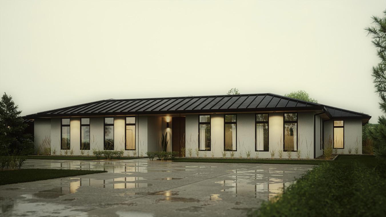
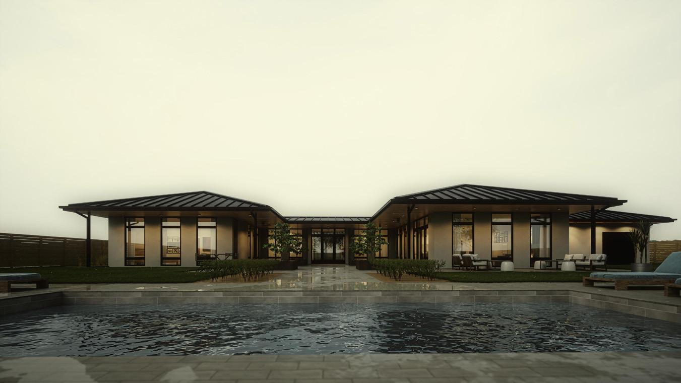
Street Presence
The Premise behind Court House lies in the simplicity found at the intersection between the design and intent. In response to a client request, we designed a nondescript, single-story house for their family, that appears rather unassuming from the street, intentionally not drawing any attention to itself. After a few iterations in design, we were settled upon a final design.
PROJECT
Site Plan
// Nicholas Place
16
#: REF.
REF. SHEET: DRAWN: DATE: ARCHITECTS SUPPLEMENTAL INSTRUCTIONS HANSON RESIDENCE 12522 RICKY ROAD PASCO, WA 99301 2006 A101 Author 03/19/07 N 0' 20'40' 10' AAHJ COMMENTS 1 04.02.21
#: A.S.I.
BUILDING:
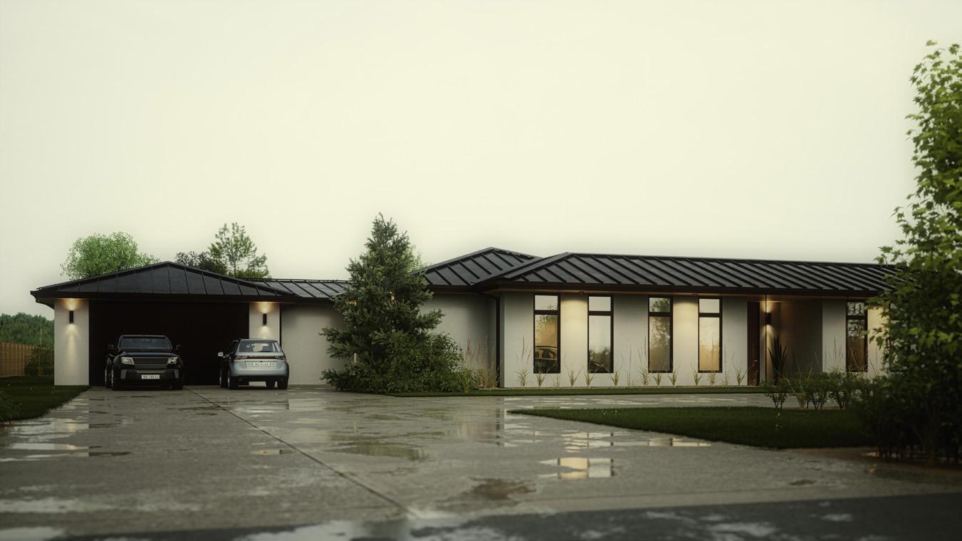
Main Entry Garage Entry Back Entry
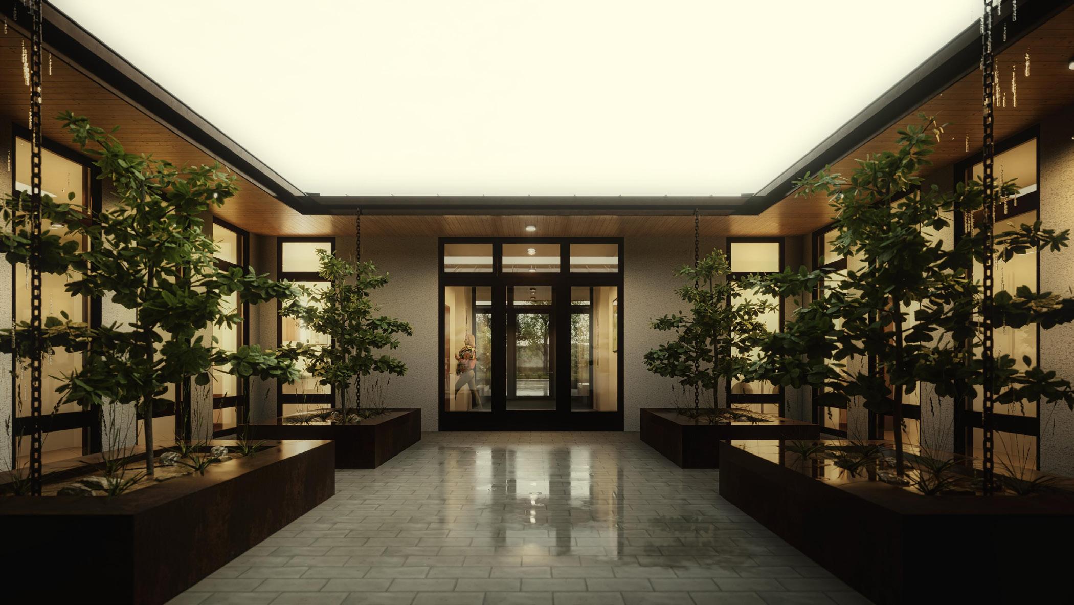
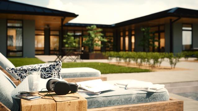
Courtyard Intent
From the street, the residence is intentionally rather plain. The fenestration consists of rhythmic window spacing, a garage door and a small recessed alcove centered on the entry face, aiming draw you into the unsuspecting main entry. Upon entering the threshold the space opens up into a spacious courtyard, which serves as the central element in which the wings of the house radiate around.
 Entry Courtyard
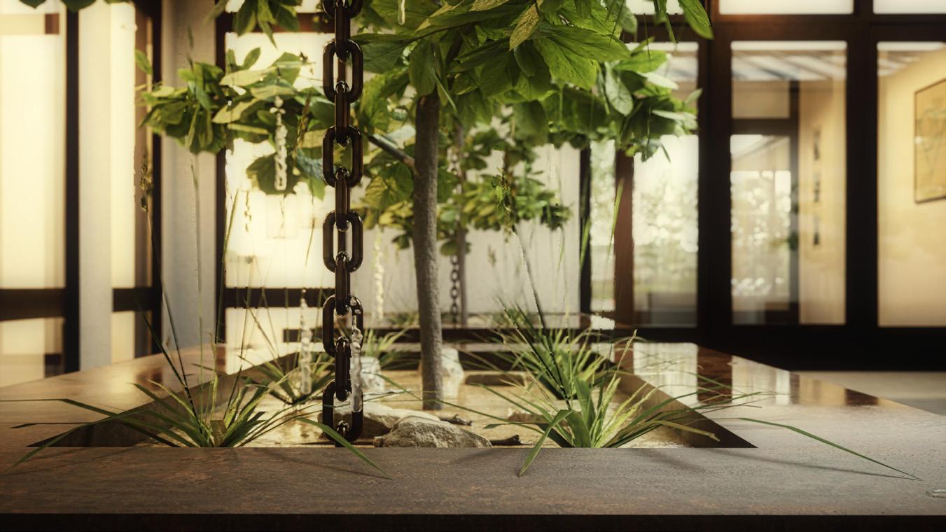
Nicholas Place // 17
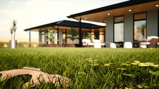
Integral Planters
One wing of the house which serves as a functional element houses the utilitarian functions, as well as the family leisure activities, whilst the other wing contains personal living spaces.
Additionally, both of these wings extend further towards the rear of the property and surround an open-ended court yard to the back patio, which circulates continuously on a defined axis to the swimming pool.
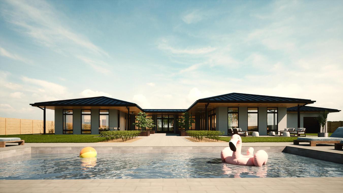
Floor Plan Pool Party 18 // Nicholas Place
Distribution
Program
0 32' 48' 4'8' 12' 16' N 0 32' 48' 4'8' 12' 16' N PROGRAM LEGEND Courtyard Mech/Storage Garage Pantry Storage Shop Pool Equip Kitchen / Dining Living Powder Foyer Laundry Main Bed Main Bath Bath Kids/Guest Bed 1 2 3 4 5 6 7 8 9 10 11 12 13 14 15 16 17 1 2 3 4 5 6 7 8 9 10 11 12 13 14 15 15 16 17 17
Finality of Execution
Thus, with the completion of this project, the concept of riding the fine line between the duality of a subdued presence on the street, coupled with eccentricity beyond a threshold, holds up to be inherently successful in its execution.
Exploded Iso
Nicholas Place // 19
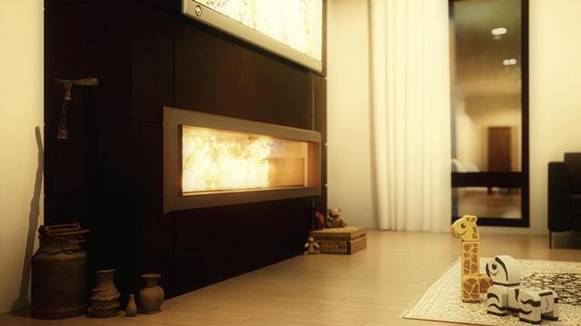
House Vignettes
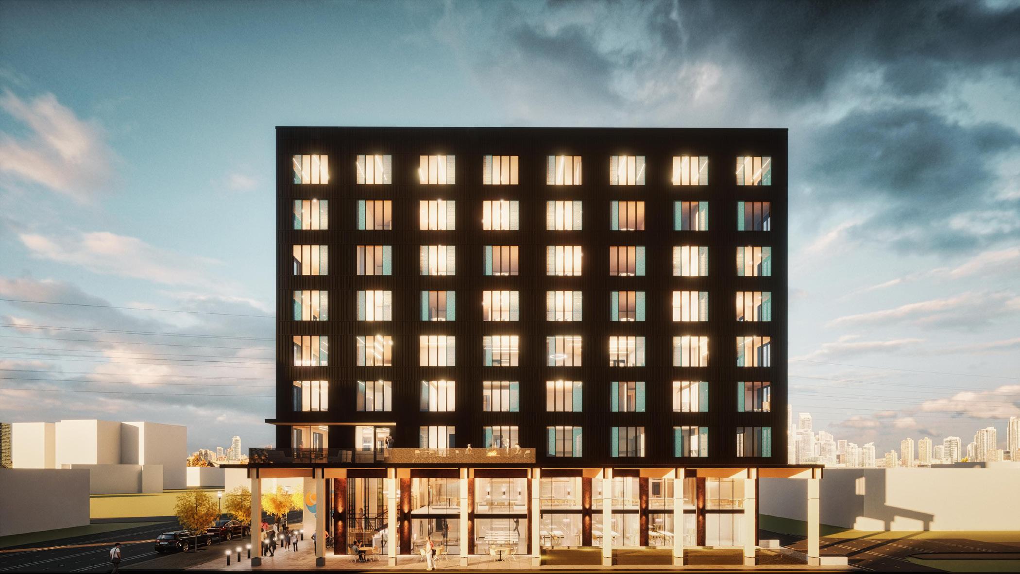
HENDERSON TOWER
Mixed-Use CLT Tower
Seattle, Washington
Status: In-Design (SD) hoist.
Expanded Info:
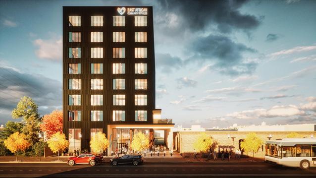
Client: East African Community Services
GSF: ± 48,400
Duration: 09/21 - Present
Responsibilities:
Team Member through Feasibility + SD
Conception
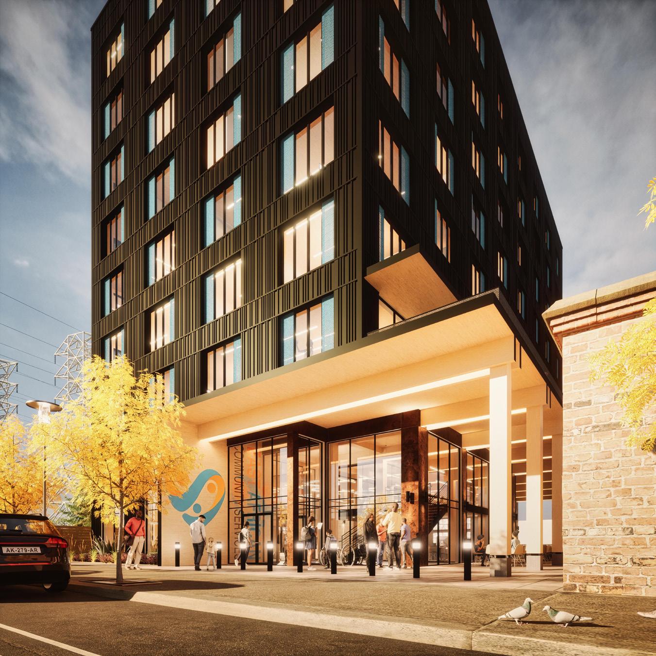
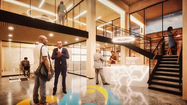
The origin of the Henderson Tower project starts with the dreams of an organization looking to further expand their footprint in the city of Seattle, and the surrounding area, with their first property, designed with them, and for them, as an embodiment of their aspirations to help the community they represent, while also acting as a positive influence on the rest of the city.
20 // Nicholas Place
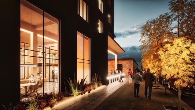
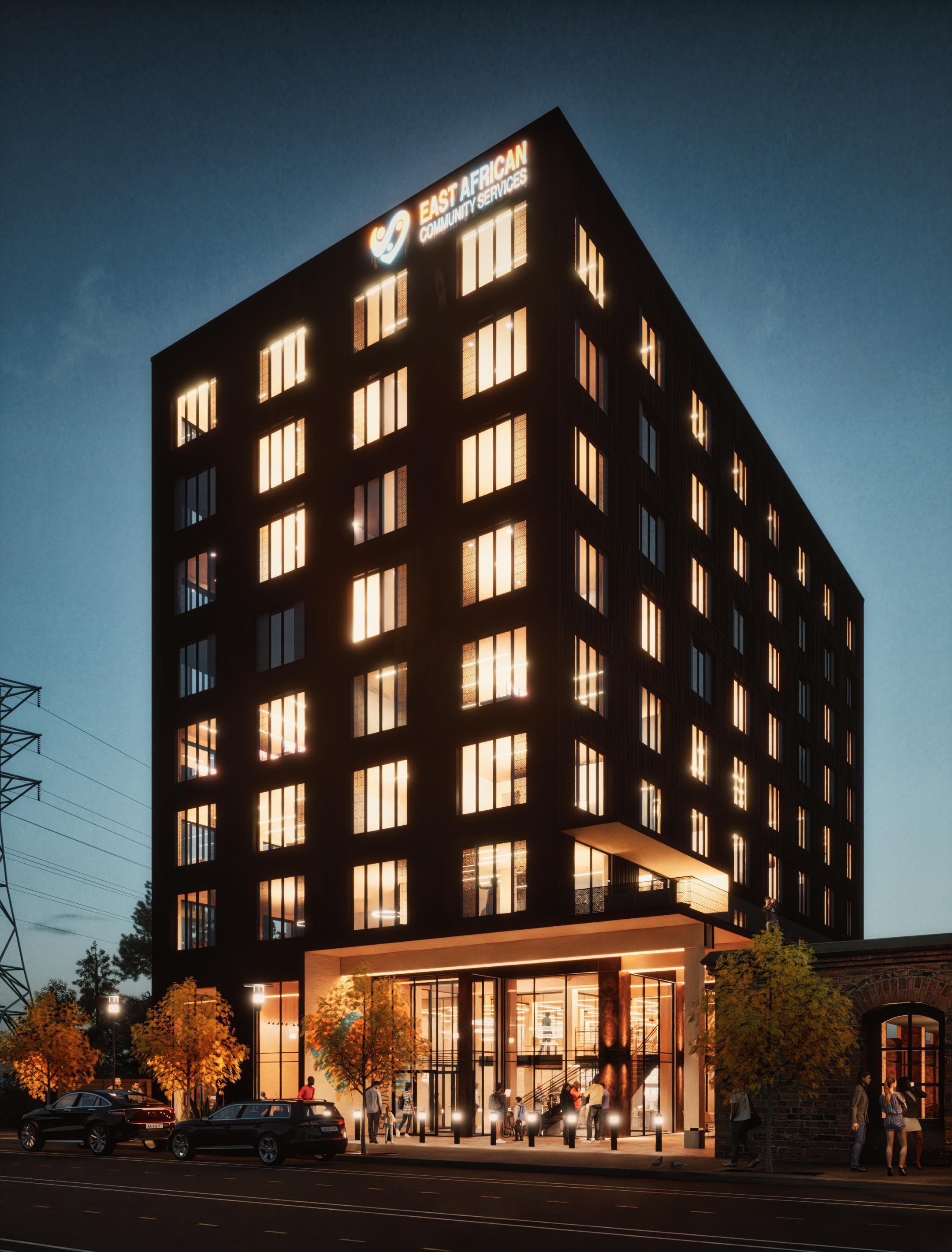
Main Entry
Alley Elevation
Nicholas Place // 21 LEGEND CLT Feature Walls Mass Timber Feature Beams + Columns Concrete Parking Garage CLT Floor Plates + Timber Columns Circulation Cores Corrugated Steel Siding Steel Plate Paneling Perforated Steel Accent Panels Exterior CLT Walls Storefront Glazing Systems Window Systems Rooftop Playground + Mech 1 2 3 4 5 6 7 8 9 10 11 12 Exploded Iso 1 2 3 4 5 6 7 8 9 10 11 12
22 // Nicholas Place Saint John, WA 99171 DATE ISSUE DATE INFORMATION hoist. NOT FOR CONSTRUCTION ARCHITECT S1 + S2 PLANS A2.0 EACS 4354 HENDERSON ST SEATTLE, WA 98118 2120 1" = 10'-0" S1 GARAGE PLAN 1" 10'-0" S2 GARAGE PLAN Saint John, WA 99171 CONSULTANT DATE ISSUE DATE INFORMATION hoist. NOT FOR CONSTRUCTION ARCHITECT S1 + S2 PLANS A2.0 EACS 4354 HENDERSON ST 01.18.22 FEA 1" 10'-0" S1 GARAGE PLAN PO Box 342 Saint John, WA 99171 DATE ISSUE DATE hoist. NOT FOR CONSTRUCTION ARCHITECT L1 + MEZZANINE PLANS A2.1 EACS 4354 HENDERSON ST SEATTLE, WA 98118 2120 1" 10'-0" L1 FLOOR PLAN 1" 10'-0" L1.5 MEZZANINE FLOOR PLAN Saint John, WA 99171 CONSULTANT DATE INFORMATION hoist. NOT FOR CONSTRUCTION ARCHITECT REVISIONS L1 + MEZZANINE PLANS A2.1 EACS 4354 HENDERSON 01.18.22 FEA 1" 10'-0" L1 FLOOR PLAN 1" 10'-0" L1.5 MEZZANINE FLOOR PLAN PO Box 342 Saint John, WA 99171 DATE ISSUE DATE hoist.
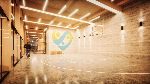
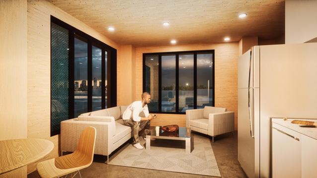
FOR CONSTRUCTION ARCHITECT L2 + L3 PLANS A2.2 EACS 4354 HENDERSON ST SEATTLE, WA 98118 2120 1" 10'-0" L2 FLOOR PLAN 1" 10'-0" L3 FLOOR PLAN Saint John, WA 99171 CONSULTANT DATE ISSUE DATE INFORMATION hoist. NOT FOR CONSTRUCTION ARCHITECT REVISIONS L2 + L3 PLANS A2.2 EACS 4354 HENDERSON ST 01.18.22 FEA 1" = 10'-0" L2 FLOOR PLAN 1" 10'-0" L3 FLOOR PLAN PO Box 342 Saint John, WA 99171 JOB NUMBER DATE ISSUE DATE hoist. NOT FOR CONSTRUCTION ARCHITECT L4 + L5 PLANS A2.3 EACS SEATTLE, WA 98118 2120 1" 10'-0" L4 FLOOR PLAN 1" 10'-0" L5 FLOOR PLAN Saint John, WA 99171 DATE ISSUE DATE INFORMATION hoist. NOT FOR CONSTRUCTION ARCHITECT L4 + L5 PLANS A2.3 EACS 4354 HENDERSON ST SEATTLE, WA 98118 2120 01.18.22 FEA 1" 10'-0" L4 FLOOR PLAN 1" 10'-0" L5 FLOOR PLAN Saint John, WA 99171 DATE ISSUE DATE INFORMATION hoist. NOT FOR CONSTRUCTION ARCHITECT L6 + L7 PLANS A2.4 EACS 4354 HENDERSON ST SEATTLE, WA 98118 2120 FEA 1" = 10'-0" L6 FLOOR PLAN 1" 10'-0" L7 FLOOR PLAN 1" = 10'-0" L6 FLOOR PLAN 1" 10'-0" L7 FLOOR PLAN L8 | Education, Resources + Unemployment Roof | Playground PO Box 342 Saint John, WA 99171 JOB NUMBER DATE ISSUE DATE hoist. NOT FOR CONSTRUCTION ARCHITECT L8 + ROOF PLANS A2.5 EACS 4354 HENDERSON ST SEATTLE, WA 98118 2120 1" 10'-0" L8 FLOOR PLAN 1" 10'-0" ROOF PLAN 1" = 10'-0" L8 FLOOR PLAN 1" 10'-0" ROOF PLAN L6 | Residential Units L7 | Residential Units L4 | Computer Lab, Classrooms, Lounges, Fitness L5 | Residential Units L2 | Community, Grocery, Wellness L3 | Admin Offices, Conference, Development L1 | Classrooms, Cafe, BBall, Recording Studio L1.2 | Mezzanine, Math + Robotics Lab P2 | Parking P1 | Parking Tower Vignettes
NOT
Formation
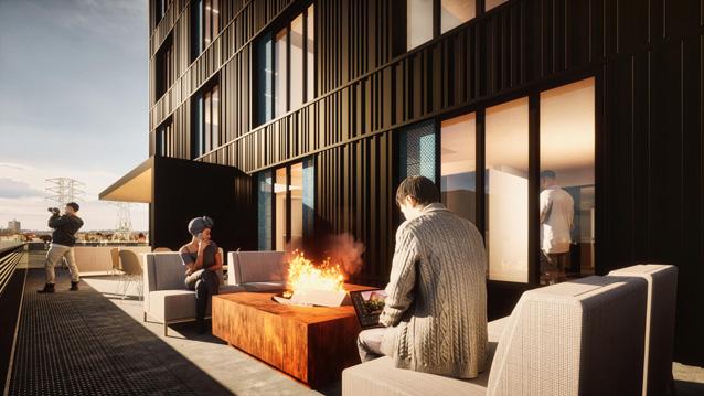
Through the design process, the lofty ambitions started to take shape in the form of an 8 story CLT tower, comprised of a rather optimistic program, with the intent of becoming a catalyst for change in an under-developed area, whilst also serving as a community center for the organization’s people they aim to assist.
// 23 Street View
Nicholas Place
WOODLAND REPOSE
Luxury Condominiums
Undisclosed, Idaho
Status: Unbuilt hoist.
Expanded Info:
Client: The Wolff Company
GSF: ± 34,000
Duration: 02/21 - 03/22
2022 AIA Citation Award - Unbuilt Project (hoist.):
• April 2022
• AIA Spokane
• AIA Spokane 2022 Citation Award for the project “Woodland Repose”
Responsibilities:
Team Member through Feasibility + SD
Initial Conception
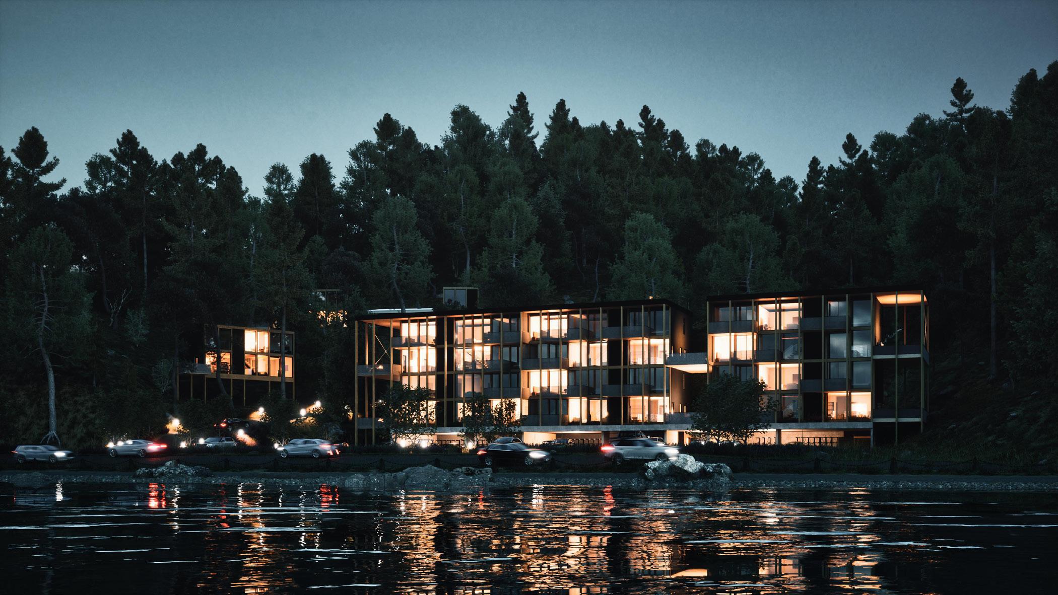
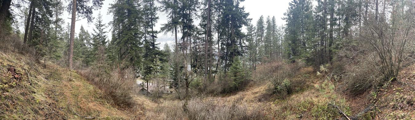
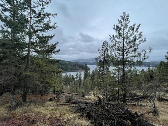
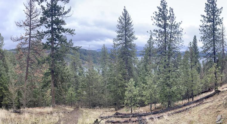
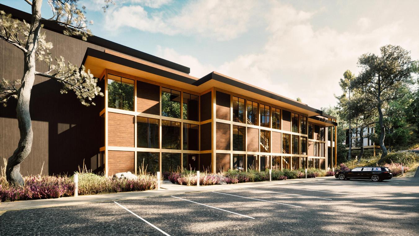
Tucked away in the hillside of a heavily neglected woodland area, Woodland repose aims to create a 6-unit premiere condo building, dissolving into the surrounding forest while concurrently looming over the neighboring lake.
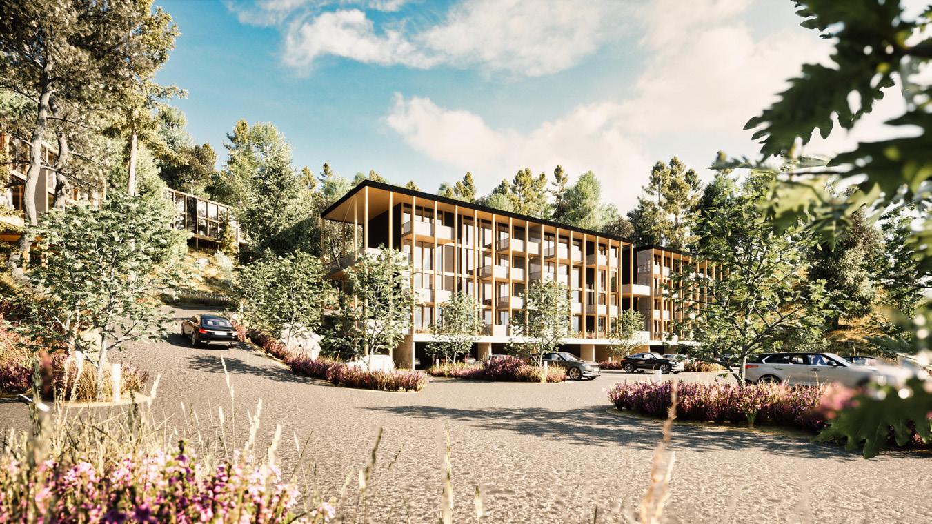
Ground View Approach
Site Plan
24 // Nicholas Place
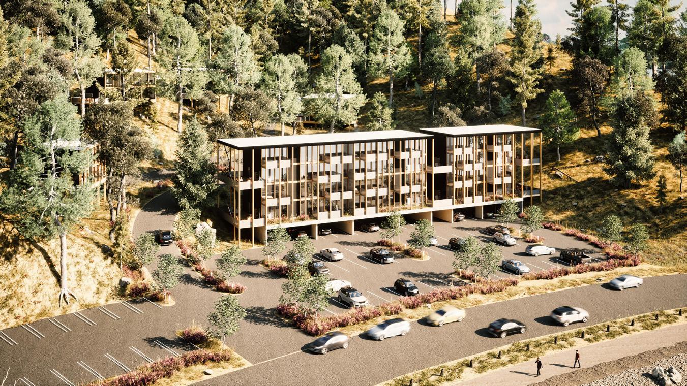
Aerial Site View
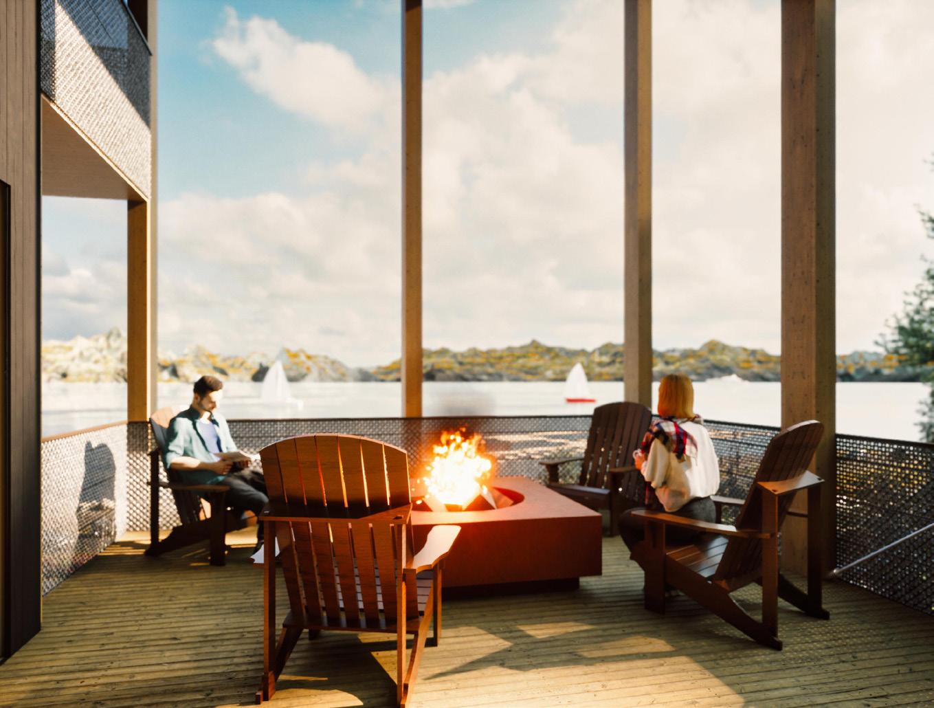
Deck View
0 160' 320' 480' 80' N 0 160' 320' 480' 80' N 0 160' 320' 480' 80' N
Concept Expanded
Conceptually, the project aspires to create a demarcation between the surrounding areas while also attempting to be a catalyst for the transformation of the boundaries of cohesion between the long-held dichotomy of the built and the unbuilt.
Nicholas Place // 25
SE NW NE SW
Existing Site Conditions
Lake View
26 // Nicholas Place Simplified Program Distribution Level 1 - Typical Level 2 - Typical 0'8' 16' 4' N Entry Vestibule + Circulation Core Tuck-Under Parking Substructure Elevated 3-Bedroom Condos (Typ of 6)
Nicholas Place // 27 LEGEND CLT Shear Walls CLT Slabs Column + Beam Structure Privacy Screen Balconies (SM) Balconies (LG) Roof Plates + RTU Tuck-Under Parking Perimeter 1 2 3 4 5 6 7 8 1 2 3 4 5 6 7 8 Exploded Iso
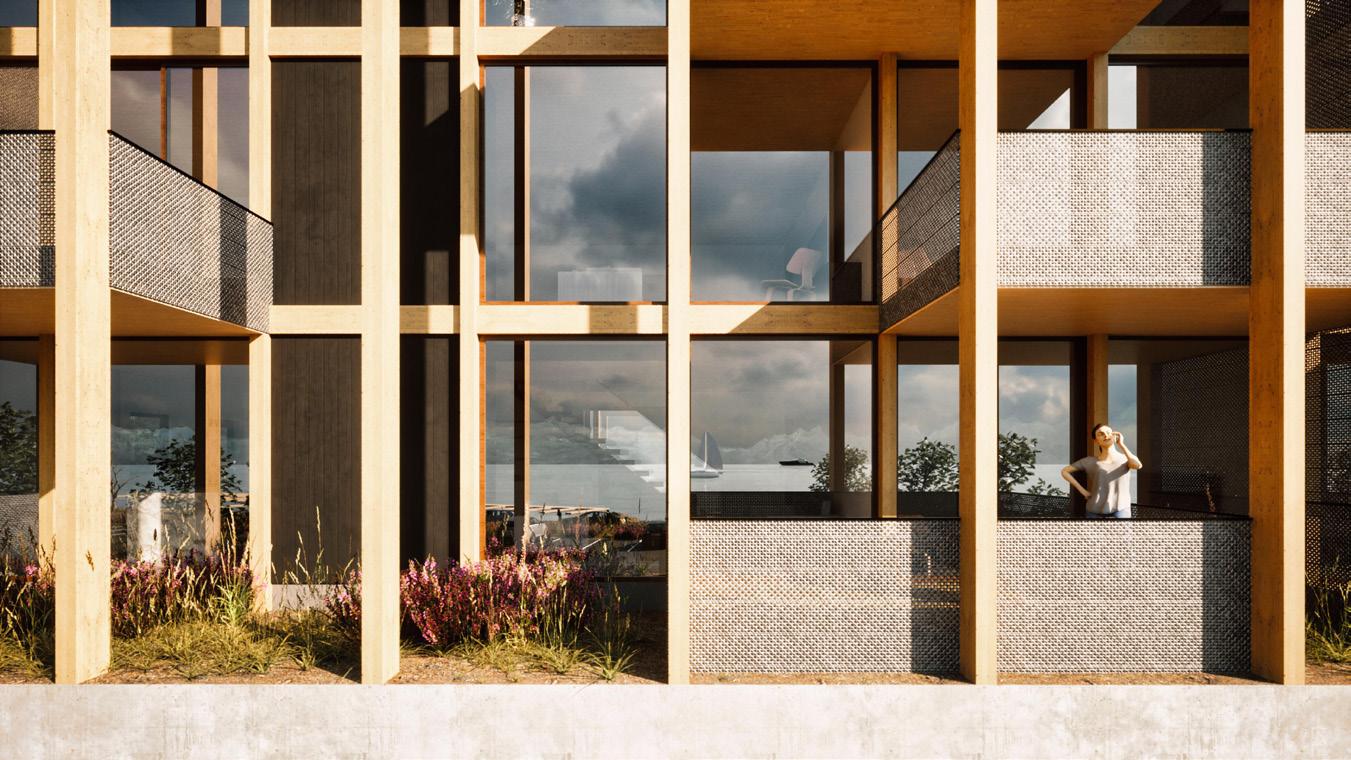
Transformative Relationships
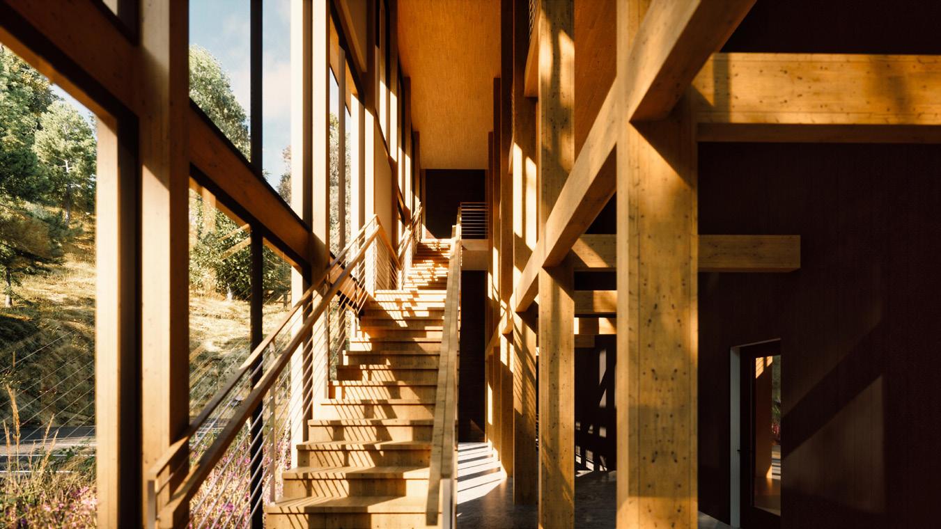
The transformative character of the building and its programmatic organization heavily relies on a concise structural grid, blurring the lines between interior and exterior through the exposed horizontal and vertical structure, creating both a means of stability, but also as a means of composition through the aesthetic rhythm and fenestration of the building as a prominent element of the facade.
28 // Nicholas Place
SE ISO -Front
ISO -Back
ISO -Front NW
Entry
Balcony System
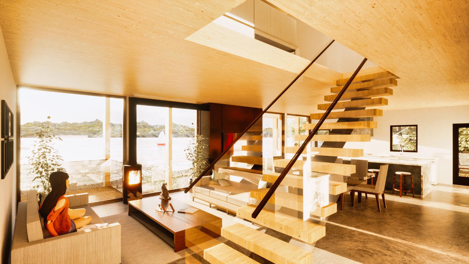
Feature Stair
Duality of Place
The continuation of the structural grid the extents of the envelope creates opportunities for compositions of irregular patterns of both large and small balconies, serving as appendages to each respective unit on both the front and sides of the building. With the vertical structure accentuating a contrast with the adjacent hillside while simultaneously mimicking the surrounding forest, a duality of place is formed between the structure and the site.
Nicholas Place // 29
Perspective Longitudinal Section
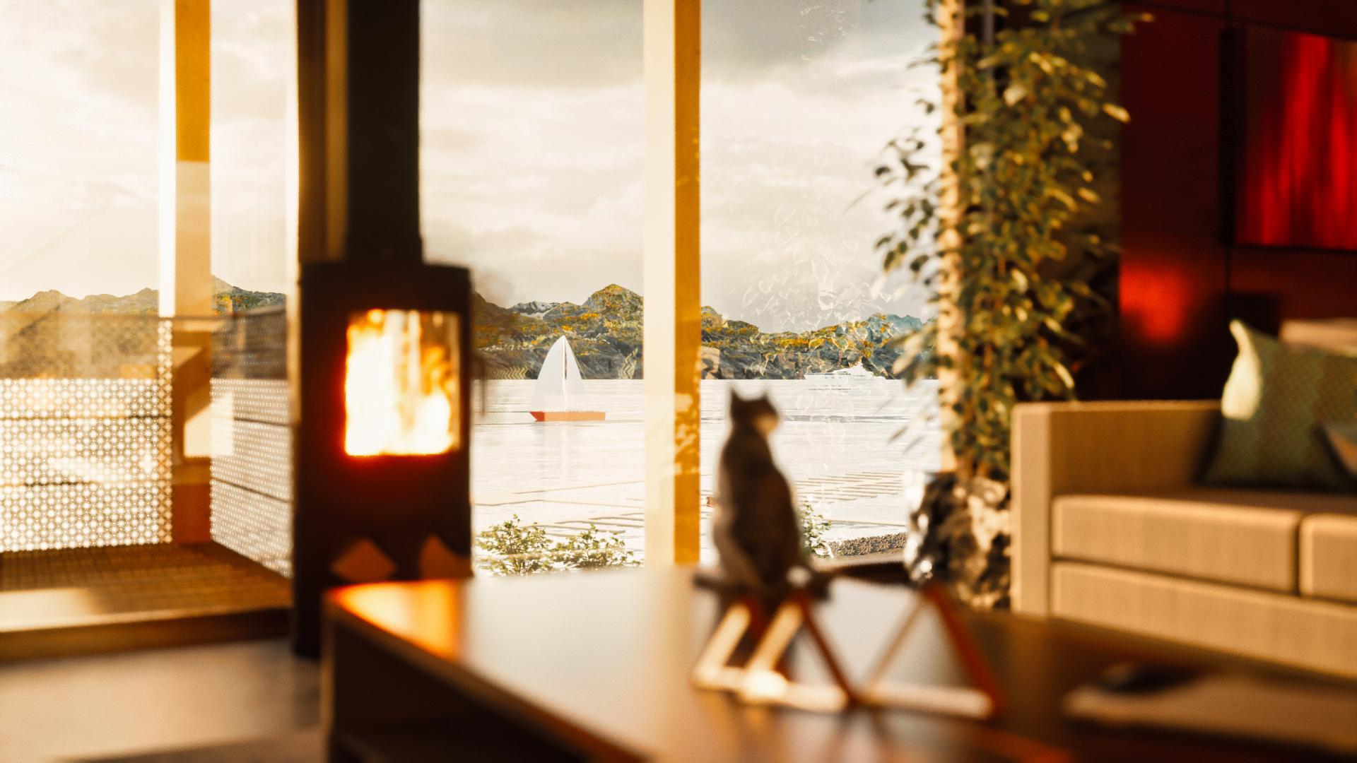
The Bay
Living
KA2 CLUBHOUSES
KA2 CLUBHOUSES
Project-Based & Prototypes
Project-Based + Prototypes
Schematic Design through Construction Administration
Washington, Idaho, Nevada
July 2018 - Present KATERRA
Status: Built - Completion Dates Vary KATERRA
Expanded Info:
Client: Various
Duration: 07/17 - 03/19
Architecture as a Product
Responsibilities:
Team Member through all Design Phases. Schematic Design through Construction Administration.
Architecture as a Product
One of the hardest things to grasp with the visionary model at Katerra is to think about architecture differently than the rest of the industry. Instead of referring to each structure as architecture, it’s all about the creation of a product. Eventually, at the end of the road, each component (even the building itself) will be assigned a product number and made available as a product line in a catalog.
One of the hardest things to grasp with the visionary model at Katerra was to think about architecture differently than the rest of the industry. Instead of referring to each structure as architecture, it was all about the creation of a product. Eventually, at the end of the road, each component (even the building itself) was to be assigned a product number and made available as a product line in a catalog.
At Katerra, I am enlisted on the Clubhouse Team, which is a very small team dedicated to the development and detailing for all of the amenity building “clubhouses” present on all of the residential developments using the Katerra KA2 product model.
At Katerra, I was enlisted on the Clubhouse Team, which was a very small team dedicated to the development and detailing for all of the amenity building “clubhouses” present on all of the residential developments using the Katerra KA2 product model.
Every project clubhouse is dependent on a series of criteria with variables consisting mainly of development size, geographical location and site orientation. With these variables defined, the product can then be identified, assembled and compiled as a complete product set.
Every project clubhouse was dependent on a series of criteria with variables consisting mainly of development size, geographical location and site orientation. With these variables defined, the product can then be identified, assembled and compiled as a complete product set.
Throughout my time there, I have worked on 7 clubhouses, spanning from the Schematic Design phase all the way through Construction Administration, in addition to product development and prototyping efforts.
Throughout my time there on the clubhouse team, I worked on seven clubhouses, spanning from the schematic design phase, all the way through permitting and construction administration. Additionally, I was a part of the product development and prototyping efforts of the clubhouse product as well, working towards a complete catalog of products offered in the KA2 product line.
//
30
Nicholas Place
Urban Sprawl
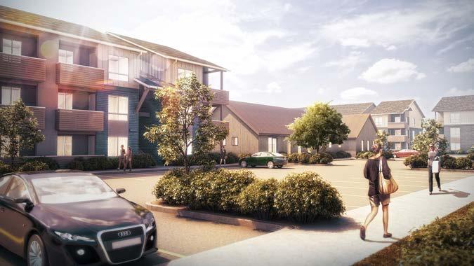
Clubhouse Street Conditions
Typical Residential Development with Centralized Clubhouse
// Nick Place
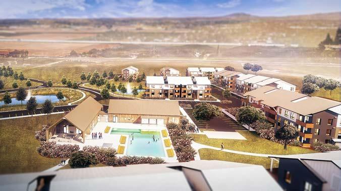
Typical Clubhouse Pool Deck
22
Standardization
Within the development of the Clubhouse product, similar to other building types at Katerra, standardization had a very important place in the design process. The clubhouse product was designed into a series of components, which would in theory, be able to be swapped out in a “plug-and-play” fashion, and assembled. In order for this to be successful, each component relies upon precise coordination between all departments, namely MEP and structural.
Developmental Processes
Due to the ever-evolving nature of Katerra, design, construction and documentation processes were in a constant state of development. In my earlier projects, we were operating similar to a traditional firm; working through the use of various consultants with stick-built construction. As time progressed however, the focus shifted to align with the core drive of the company; automation and fabrication.
The two most recent project-related clubhouses were designed for mass fabrication through panelization at the Katerra factory in Phoenix and set to be completely vetted through undocked component design. These projects were then used to kick off the standardization process as a full “kit of parts” which could then be used, adjusted and linked into other projects for future use as an official Katerra product offered to developers and customers.
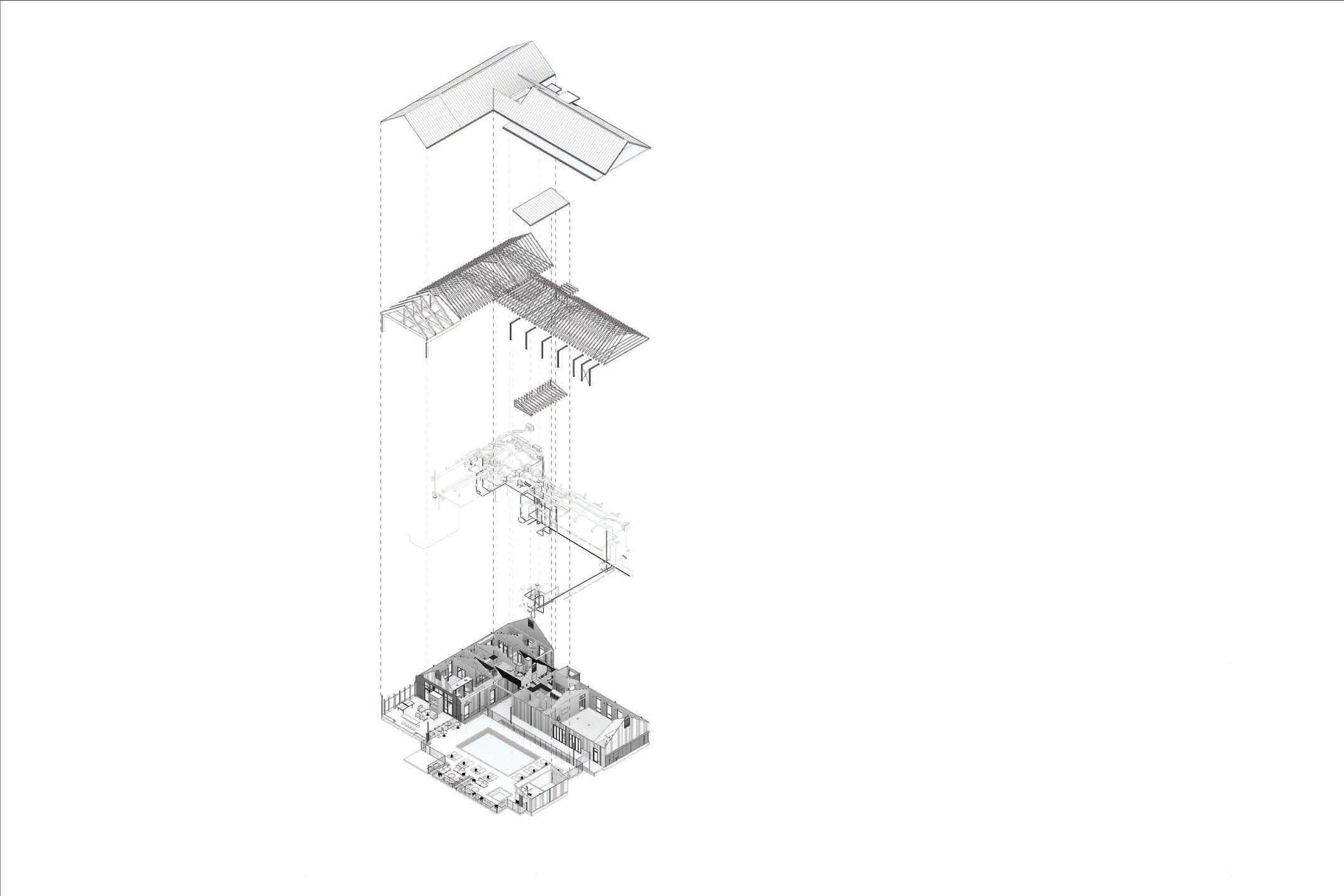
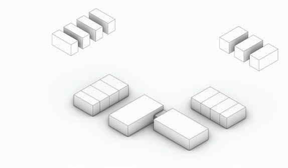
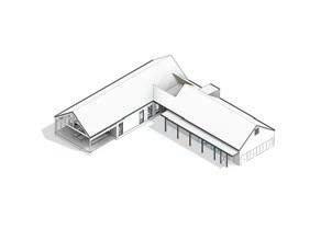
Nicholas Place // 31 Structural Roof Enclosure Skin & Program
Clubhouse Composition Nick Place // 23
Typical
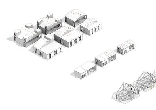
The process by which products are broken down and divided into standard parts is rather simple to understand in terms of the clubhouse product. The base program is given to us by the clients as a basis for their requirements on all of their projects.
The process by which products are broken down and divided into standard parts is rather simple to understand in terms of the clubhouse product. The base program is given to us by the clients as a basis for their requirements on all of their projects. Those requirements are then organized into multiple wings; most commonly being the Club Wing, which contains the leasing offices and club facilities, and the Fitness Wing, which contains mail rooms and a fitness facility. Those wings are then broken down into separate components, which can then be swapped out with a catalog of components, which have already been designed, engineered and fully vetted with component design.
Those requirements are then organized into multiple wings; most commonly being the Club Wing, which contains the leasing offices and club facilities, and the Fitness Wing, which contains mail rooms and a fitness facility. Those wings are then broken down into separate components, which can then be swapped out with a catalog of components, which have already been designed, engineered and fully vetted with component design.
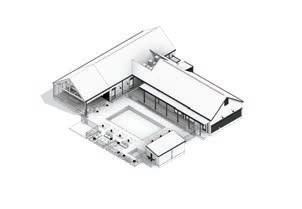
BIM plays a huge role in this process as it is imperative that all of the pieces in the catalog are populated with all data required for proper documentation (building assemblies, door + window schedules, finish information, etc.) These parts then live within their own file, organized by category and catalogued on a grid.
BIM plays a huge role in this process as it is imperative that all of the pieces in the catalog are populated with all data required for proper documentation (building assemblies, door & window schedules, finish information,etc.) These parts then live within their own file, organized by category and catalogued on a grid.
All of these parts are then inserted into corresponding files divided by their destination wing, which is then further linked into a host file, where it is skinned with cladding and connected via the knuckle entry component.
All of these parts are then inserted into corresponding files divided by their destination wing, which is then further linked into a host file, where it is skinned with cladding and connected via the knuckle entry component.


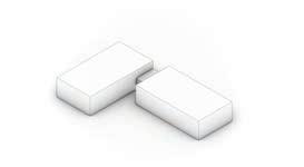


32 // Nicholas Place U-Scheme Angled-Scheme L-Scheme Residential Development Site Conditions Geographic Location # of Units Clubhouse Size Clubhouse Style Clubhouse Configuration Programmatic Layout Roof Type Architectural Features Skin Materiality Complete Clubhouse Product Design Production Process Standardization at its core
Linear Scheme CLUBROOM CONFERENCEROOM EXTERIORPATIO Interchangable Building Components Expanded Components Building Configurations Club Wing Fitness Wing Wing Components Wing Components Component Options Component Options Knuckle Connection 24 // Nick Place Standardization at its core
PROJECT-BASED CLUBHOUSES
Orientation for Design
Orientation for Design
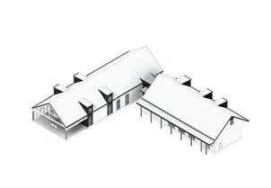
The layout and orientation for the clubhouse as a whole is governed by a surprisingly large assortment of criteria. These range from geographic location, development size and site conditions. The site conditions specifically are what drives the configuration, with the L-Scheme being the most common, but often are organized into other iterations to match site conditions and overall master plan intent for the surroundings.
The layout and orientation for the clubhouse as a whole is governed by a surprisingly large assortment of criteria. These range from Geographic location, development size and site conditions. The site conditions specifically are what drives the configuration, with the L-Scheme being the most common, but often are organized into other iterations to match site conditions and overall master plan for the surroundings.
Architectural style of the clubhouse is determined by the geographic location, which are designed into a standard to align with the vernacular architecture of the surrounding region. This also affects other aspects of the building, such as roof type (flat, shed, pitched), materiality and certain architectural features (screens, dormers, etc.)
Architectural style of the clubhouse is determined by the geographic location, which are designed into a standard to align with the vernacular architecture of the surrounding region. This also affects other aspects of the building, such as roof type (flat, shed, pitched), materiality and certain architectural features (screens, dormers, etc.)
The Clubhouses were divided into 3 sizes; S, M + L. The sizes of these clubhouses are purely determined by the overall number of apartment units that will exist in the final development. If the number of units aligns within one of the three tiers, the size is then chosen and moved on to the set of standard structural grid sizes unique to each size.
The Clubhouses are divided into 3 sizes currently; S, M & L. The sizes of these clubhouses are purely determined by the overall number of apartment units that will exist in the development. If the number of units aligns within one of the 3 tiers, the size is then chosen and moved on to the set of standard structural grid sizes unique to each size.
Project vs. Product
Project vs. Product
The process of prototyping vs. projectbased design was a chaotic development, but one that had to occur. Both sectors took from each other, as well as influence each other. The prototyping environment allowed for development based upon base building codes and accessibility requirements without having to deal with local jurisdictional requirements. Projects on the other hand were another story, often driving non-standardized changes to the designs, which in the end would influence a significant change in the prototype if a trend occurs in the project environment that can be optimized, and in the end used to create a better product.
The process of prototyping vs. projectbased design is a chaotic development, but one that must take occur. Both sectors take from each other and influence the other. The prototyping environment allows for development based upon base building codes and accessibility requirements without having to deal with local jurisdictional requirements. Projects on the other hand are another story, often driving non-standardized changes to the designs, which in the end might influence a significant change in the prototype if a trend occurs in the project environment that can be optimized, and in the end used to create a better product.
Nicholas Place // 33
LARGE
CLUBHOUSE PROTOTYPES
MEDIUM
SMALL
Nick Place // 25
The Typical Clubhouse
Following is a typical clubhouse product, their basic composition and clubhousespecific standard details.
34 // Nicholas Place Overall Floor Plan 01 01 03 03 02 02 06 06 04 04 05 05 A.10.401 AA A.10.401 AA A.10.402 EE A.10.402 EE A.10.401 CC A.10.401 CC A.10.401 DD A.10.401 DD A.10.402 GG A.10.402 GG A.10.403 HH A.10.403 HH A.10.402 FF A.10.402 FF F F E E D D C C SPA POOL GAME ROOM 108 KITCHEN 110 MENS RR 117 JAN 119 IDF 120 MPOE/ ELEC 121 FITNESS 118 YOGA STUDIO 123 3 A.10.301 A.10.403 KK A.10.403 KK 1 A.10.300 3 A.10.300 1 A.10.301 2 A.10.300 20-0 " 38-0 42-0 26'-0" 14'-6" 19'-0" 30'-6" 26'-0" POOL RR 115 POOL TREATMENT ROOM 114 WOMENS RR 116 MEDIA LOUNGE 109 PATIO 100 WORK ROOM 104 MGR. OFFICE 105 LEASING BOH 103 MAIL ROOM 112 116'-0" A A B B 07 07 08 08 40'-0" 100-0 " POOL EQUIPMENT 113 40-0 A.10.401 BB A.10.401 BB A.10.403 JJ FIREPLACE LOUNGE 111 CONFERENCE 107 OFFICE 106 CONCIERGE 102 ENTRY 101 FIRE RSR 122 A.10.111 01 A.10.112 01 4 A.10.300 5 A.10.301 4 A.10.301 13'-1" 12'-2" A.10.403 LL A.10.403 LL 110-10 " 49-2 15-11/8" POOL DECK 30° 8'-0" N 0 16' 24' 2'4'6'8' METAL FENCE PER LANDSCAPE
26 // Nick Place
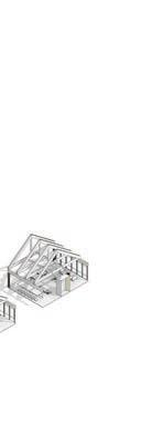
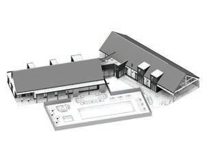
Nicholas Place // 35 Glulam Exterior Patio CLT Entry CLT Steel Canopy System Exploded Non-Typical Components Nick Place // 27
206.430.2766 nplace.np@gmail.com
