
NGI A/S Virkelyst 5 DK-9400 Nørresundby T: +45 98 17 45 00 E: ngi@ngi-global.com NGI Italy Via Guglielmo Jervis 4 IT-10015 IVREA TO T: +39 077 568 7010 E: ngi@ngi-global.com NGI Inc. USA 805 Satellite Blvd Suwanee, GA 30024, USA T: +1 (646) 201 9410 E: sales@ngi-global.com NGI GmbH (drum motors only) Ottostraße 15b DE-41836 Hückelhoven-Baal T: +49 (0) 2433 96 422 90 E: drivetech@ngi-global.com ngi-global.com Thanks for your interest See more at www.ngi-global.com All NGI hygienic components are design and patent protected Seismic levelling feet
The only seismic levelling feet in the world designed and calculated according to the international new zealand seismic standard
The NGI seismic foot is capable of withstanding earthquakes due to its ability to withstand combinations of vertical and horizontal loads


Seismic Levelling feet


Reliable seismic security
We provide the optimal solution for your application
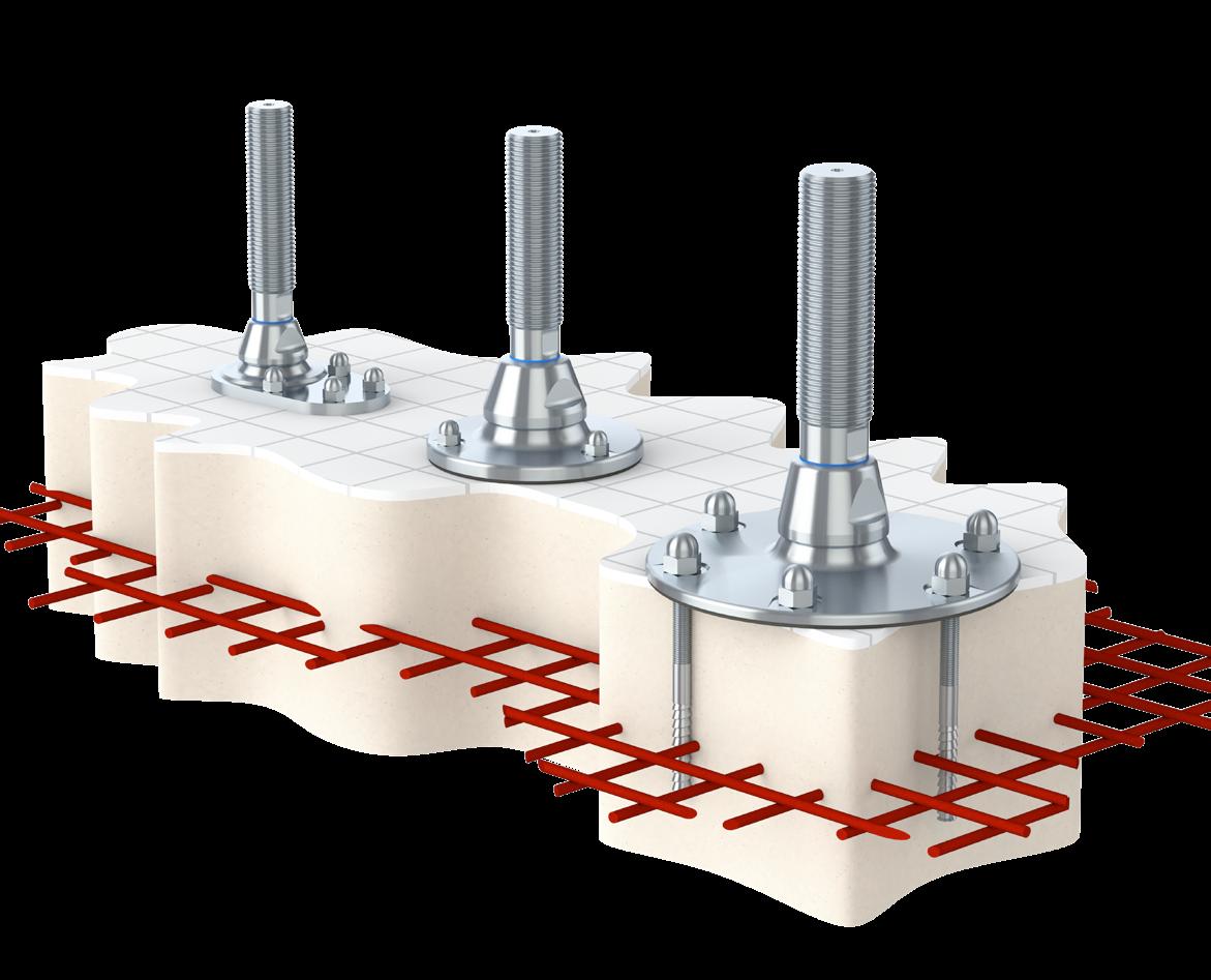
The only hygienic seismic levelling feet in the world designed and calculated according to the international New Zealand seismic standard.
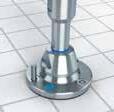
Self-draining surfaces, sealed movable parts and no exposed thread secures absolute minimum cleaning and maximum product safety.
The design and patent protected seismic levelling foot is the optimal choice for machinery, equipment, tanks and vessels located in areas subject to earthquakes and also has to to comply with the strictest hygienic requirements.
Our seismic levelling foot is capable of withstanding earthquakes due to its’ ability to withstand combinations of vertical and horizontal loads. Additionally, the certified hygienic type is designed in accordance with the 3-A and EHEDG hygienic standards and certified in accordance with USDA hygienic standard.
Enhanced food safety
A complete hygienic design minimizing risks of cross-contamination
Plug&Play installation
Minimize water usage and use of cleaning detergents
Go to ngi-global.com/products/levelling-feet/seismic-levelling-feet/ to read more and see our product range.
6 5
Innovation by NGI
Seismic Levelling feet
Our seismic levelling foot has been developed and tested using the Finite Element Method (FEA) and is compliant with the governmental regulations of California and New Zealand - (NZS 4219:2009).
Our seismic foot is capable of withstanding earthquakes due to its ability to withstand combinations of vertical and horizontal loads. The NGI seismic product configurator combines earthquake risk data in the geographic area with data about your specific equipment. The result of this detailed analysis will help you select the optimal solution in terms of safety and minimizing the risk of damage to your machinery and equipment caused by earthquakes.
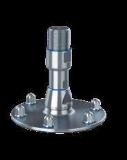
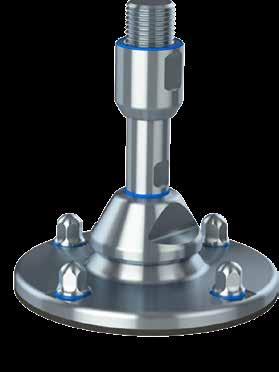
XHJSE (S)
Special Features
- Height adjustment 155 mm - 285 mm
- Certified according to USDA hygienic standard
- Designed according to the 3-A and EHEDG hygienic standards
- Available in two standard lengths per diameter size
- Comes with a hygienic sleeve
- Circular arrangement of anchors for best seismic performance
- Spindle sizes M30, M36, M42, M48 & M56 mm
Product Group Features
• Simple and fast installation with height-adjustable compact design
• Movable set-up - no concrete molding required
• Total seismic stability through bolted fastening and patented locking mechanism

• Verified through Finite Element Analysis (FEA) and calculated according to New Zealand seismic standard (NZS 4219)
• Seismic anchors chosen and approved by our experienced partner Hilti
• Optional certified hygienic nuts from NGI
• Stainless steel AISI 304/A2, 1.4301. Optional AISI 316/A4, 1.4401

HXJE (L)
Special Features
- Spindle sizes M56, M64, M72, M80 & M90 mm
- Available in two standard lengths per diameter size
- Circular arrangement of anchors for best seismic performance
- Sealed to the floor by rubber sealing
XHJSE (L)
Special Features
- Height adjustment 221 mm - 355 mm
- Certified according to USDA hygienic standard
- Designed according to the 3-A and EHEDG hygienic standards
- Available in two standard lengths per diameter size
- Comes with a hygienic sleeve
- Circular arrangement of anchors for best seismic performance
- Spindle sizes M56, M64, M72, M80 & M90 mm
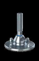
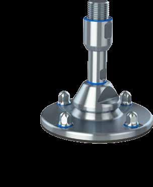
HXJE (S)
Special Features
- Spindle sizes M30, M36, M42, M48 & M56 mm
- Available in two standard lengths per diameter size
- Circular arrangement of anchors for best seismic performance
- Sealed to the floor by rubber sealing
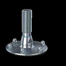
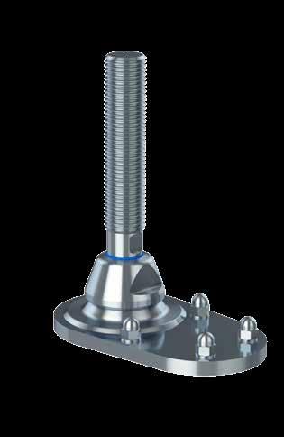
HXJCFE (S)
Special Features
- Spindle sizes M30, M36, M42, M48 & M56 mm
- Anchors decentered at one side of the spindle
- Available in two standard lengths per diameter size
- Not sealed to the floor
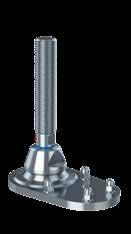
HXJCFE (L)
Special Features
- Spindle sizes M56, M64, M80 & M90 mm
- Anchors decentered at one side of the spindle
- Available in two standard lengths per diameter size
- Not sealed to the floor
11 13 17 15 21 19 Certified hygienic Certified hygienic
8 7
Accessories seismic Levelling feet
Installing seismic levelling feet requires several tools and accessories.
NGI has teamed up with HILTI, the specialist for seismic anchoring, to offer a complete seismic installtion kit for your seismic project. NGI is able to deliver all necessary accessories which ensures a quick and easy installation of the seismic levelling feet. It is important to use seismic approved accessories when fastening seismic feet. If not correctly installed it will meet neither 3A, USDA or EHEDG hygienic demands nor the seismic load specifications.
CLEANING & MAINTENANCE
This cleaning and maintenance manual describes how to clean and maintain the levelling foot once installed.
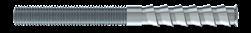
ANCHORS
Special Features
- Stainless steel A4
- PROFIS software

- Base materials: concrete (cracked), concrete (uncracked), masonry (solid)
INSTALLATION MANUAL
This installation manual describes how to install the levelling foot onto the machine or equipment for which it is intended to support.
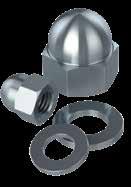
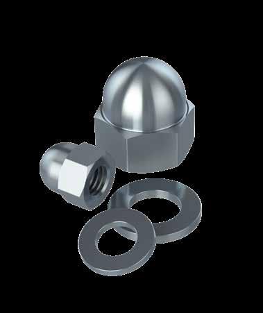
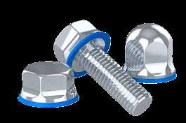
DOME HEADED NUTS & WASHERS
Special Features
- Stainless steel AISI 304/A2, 1.4301
- Standard dome-headed nuts (DIN 1587 A2)
- All dimensions available
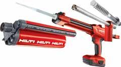
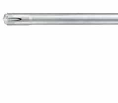
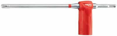
HILTI TOOLS
Special Features
Hilti’s seismic research includes detailed investigation of product performance under simulated seismic conditions and full-scale system testing.
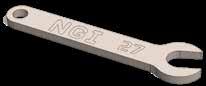
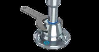
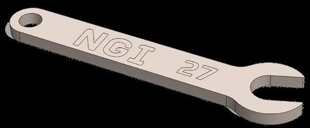
NGI WRENCHES
Special Features
XHJSE machine feet need three different wrenches for installation. NGI wrenches are laser cut and designed to fit NGI machine feet.
23 25 39 37 41 43
10 9
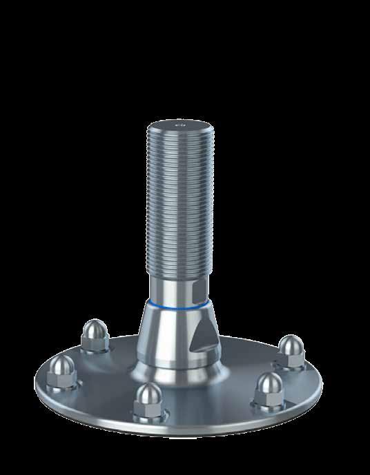
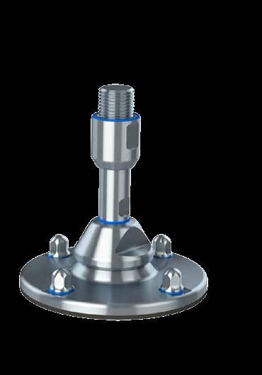
Certified hygienic Seismic levelling feet - XHJSE (S)
The design and patent protected seismic XHJSE (S) levelling foot is the optimal choice for machinery, equipment, tanks and vessels located in areas subject to earthquakes and also has to to comply with the strictest hygienic requirements.
- Total seismic stability and bolted fastening to concrete floors
- Movable set-up - no concrete moulding required
- Seismic anchors chosen and approved by our experienced partner Hilti
- Patented locking mechanism secures seismic stability
- Calculated according to international seismic standard NZS 4219
- Design verified through Finite element simulation
- Designed according to the 3-A and EHEDG hygienic standards
- Certified according to USDA hygienic standard
- Stainless steel AISI 304/A2, 1.4301. Optional AISI 316/A4, 1.4401
Available upon request:
- Official USDA hygienic certificate
- Datasheet calculations
- Installation instructions
- Cleaning & maintenance instructions
Certified hygienic
Minimized cleaning time
Minimized water usage
Certified hygienic Seismic levelling feet - XHJSE (S)


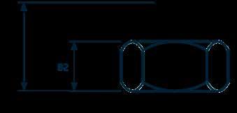
100 100 100 B A2 W2 Ø2 L1 L4 L MIN MIN MAX L5 LE C Ø E D1 Certified hygienic M30 116 77 228 105 60.000 2.100 XHJSE(S)30150 M30 178 77 288 107 60.000 1.300 XHJSE(S)30210 M36 114 77 221 103 96.000 3.500 XHJSE(S)36150 M36 179 77 288 105 96.000 2.200 XHJSE(S)36210 M42 118 82 233 109 140.000 4.900 XHJSE(S)42150 M42 179 82 298 110 140.000 3.200 XHJSE(S)42210 M48 143 82 283 120 140.000 6.900 XHJSE(S)48200 M48 203 82 343 120 140.000 4.800 XHJSE(S)48260 M56 138 82 278 115 140.000 13.100 XHJSE(S)56200 M56 203 82 343 120 140.000 8.900 XHJSE(S)56260 M30 38 41,8 55 33 193 160 RHOXS3055 M30 38 41,8 85 63 255 192 RHOXS3085 M36 46 49,8 55 36 191 158 RHOXS3655 M36 46 49,8 85 66 256 190 RHOXS3685 M42 50 54,5 55 36 200 164 RHOXS4255 M42 50 54,5 85 66 261 195 RHOXS4285 M48 55 59,5 70 35 225 190 RHOXS4870 M48 55 59,5 100 65 285 220 RHOXS48100 M56 65 69,5 70 35 220 185 RHOXS5670 M56 65 69,5 100 65 285 220 RHOXS56100 150 149 19 3 M10x160 60 28000 XHJSE150(S) 200 199 16,5 4 M12x155 80 38000 XHJSE200(S) 250 249 15 4 M16x205 101 61.000 XHJSE250(S) 300 299 12 6 M20x250 121 80000 XHJSE300(S)
FOOT PLATE Maximum nominal load = Depends on horizontal forces, request load diagram Tolerance of total height = +/-1,5 mm
SPINDLE SLEEVE
PRODUCT CODE FOOT - SPINDLE - SLEEVE EXAMPLE XHJSE150(S)-XHJSE36150-RHOXS3655 TYPE DIAMETER Ø [mm] HEIGHT B [mm] HOLES [PCS] BOLT TYPE [SIZE] POSITION E [mm] NOM PULL TENSION [N] ITEM CODE THREAD HEIGHT L1 [mm] HEIGHT L4 [mm] HEIGHT L5 [mm] L MIN [mm] NOM LOAD COMPRESSION [N] MAX HORISONTAL LOAD SHEAR [N] ITEM CODE THREAD W2 [mm] DIAMETER Ø2 [mm] HEIGHT A2 [mm] ADJUSTMENT C [mm] LEVELLING MAX [mm] LEVELLING MIN [mm] ITEM CODE
12 11
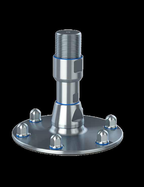
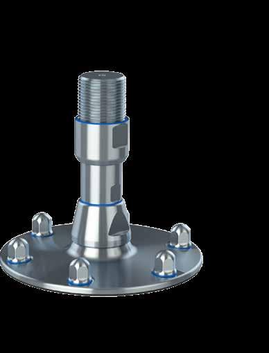
Certified hygienic Seismic levelling feet - XHJSE (L)
The design and patent protected seismic XHJSE (L) levelling foot is the optimal choice for machinery, equipment, tanks and vessels located in areas subject to earthquakes and also has to to comply with the strictest hygienic requirements.
- Total seismic stability and bolted fastening to concrete floors
- Movable set-up - no concrete moulding required
- Seismic anchors chosen and approved by our experienced partner Hilti
- Patented locking mechanism secures seismic stability
- Calculated according to international seismic standard NZS 4219
- Design verified through Finite element simulation
- Designed according to the 3-A and EHEDG hygienic standards
- Certified according to USDA hygienic standard
- Stainless steel AISI 304/A2, 1.4301. Optional AISI 316/A4, 1.4401
Available upon request:
- Official USDA hygienic certificate
- Datasheet calculations
- Installation instructions
- Cleaning & maintenance instructions
Minimized cleaning time Certified hygienic
Minimized water usage
Certified hygienic Seismic levelling feet - XHJSE (L)
100 100 100 Ø E D1 B A2 W2 Ø2 L1 L4 L MIN MIN MAX L5 LE C Certified hygienic M56 138 118 314 151 188.000 11.800 XHJSE(L)56200 M56 203 118 379 156 188.000 8.000 XHJSE(L)56260 M64 143 118 319 156 236.000 17.800 XHJSE(L)64200 M64 203 118 379 156 236.000 12.500 XHJSE(L)64260 M72 166 129 380 170 327.000 22.200 XHJSE(L)72250 M72 226 129 438 170 327.000 16.300 XHJSE(L)72310 M80 166 129 380 170 432.000 30.800 XHJSE(L)80250 M80 226 129 438 170 432.000 22.600 XHJSE(L)80310 M90 166 129 380 170 432.000 50.500 XHJSE(L)90250 M90 226 129 438 170 432.000 37.100 XHJSE(L)90310 M56 65 69,5 70 35 256 221 RHOXS5670 M56 65 69,5 100 65 321 256 RHOXS56100 M64 75 79,5 70 35 261 226 RHOXS6470 M64 75 79,5 100 65 321 256 RHOXS64100 M72 80 88 85 40 295 255 RHOXS7285 M72 80 88 115 70 355 285 RHOXS72115 M80 90 99,5 85 40 295 255 RHOXS8085 M80 90 99,5 115 70 355 285 RHOXS80115 M90 95 104 85 40 295 255 RHOXS59085 M90 96 104 115 70 355 285 RHOXS90115 250 249 22 3 M16x240 101 63000 XHJSE250(L) 300 299 19 4 M20x250 121 82000 XHJSE300(L) 350 349 18 6 M20x250 142 90.000 XHJSE350(L) 400 399 17 6 M24x330 166 126000 XHJSE400(L)
SPINDLE
SLEEVE
Maximum nominal load = Depends on horizontal forces, request load diagram Tolerance of total height = +/-1,5 mm
FOOT PLATE
PRODUCT CODE FOOT - SPINDLE - SLEEVE EXAMPLE XHJSE300(L) - XHJSE80310 - RHOXS80115 TYPE DIAMETER Ø [mm] HEIGHT B [mm] HOLES [PSC] BOLT TYPE [SIZE] POSITION E [mm] NOM. PULL TENSION [N] ITEM CODE THREAD HEIGHT L1 [mm] HEIGHT L4 [mm] HEIGHT L5 [mm] L MIN [mm] NOM LOAD COMPRESSION [N] MAX HORISONTAL LOAD SHEAR [N] ITEM CODE THREAD W2 [mm] DIAMETER Ø2 [mm] HEIGHT A2 [mm] ADJUSTMENT C [mm] LEVELLING MAX [mm] LEVELLING MIN [mm] ITEM CODE
14 13
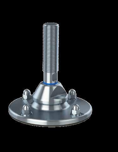
Fully-threaded seismic levelling feet - HXJE (S)
The design and patent protected seismic HXJE (S) levelling foot is the optimal choice for all machinery, equipment, tanks and vessels located in areas subject to earthquakes and at the same time need to benefit from a long levelling range.
- Simple and fast installation with height-adjustable compact design
- Movable set-up - no concrete molding required
- Total seismic stability through bolted fastening and patented locking mechanism
- Verified through Finite Element Analysis (FEA) and calculated according to New Zealand seismic standard (NZS 4219)
- Seismic anchors chosen and approved by our experienced partner Hilti
- Stainless steel AISI 304/A2, 1.4301. Optional AISI 316/A4, 1.4401
Fully-threaded seismic levelling feet - HXJE (S)
100 100 100 Ø E D1 B L4 L MIN L1 MAX L5 C LE M30 127 77 228 105 60.000 2100 HXE(S)30150 M30 187 77 288 105 60.000 1300 HXE(S)30210 M36 115 77 221 105 96.000 3500 HXE(S)36150 M36 182 77 288 105 96.000 2200 HXE(S)36210 M42 117 82 233 110 140.000 4900 HXE(S)42150 M42 182 82 298 110 140.000 3200 HXE(S)42210 M48 163 82 283 120 140.000 6900 HXE(S)48200 M48 223 82 343 120 140.000 4800 HXE(S)48260 M56 151 82 278 120 140.000 13100 HXE(S)56200 M56 216 82 343 120 140.000 8900 HXE(S)56260 150 149 19 3 M10x160 60 28000 HXJE150(S) 200 199 16,5 4 M12x155 80 38000 HXJE200(S) 250 249 15 4 M16x205 101 61.000 HXJE250(S) 300 299 12 6 M20x250 121 80000 HXJE300(S)
*L MIN is calculated without use of nut on spindle
FOOT PLATE PRODUCT CODE FOOT - SPINDLE EXAMPLE HXJE150(S)-HXE30150 TYPE DIAMETER Ø [mm] HEIGHT B [mm] HOLES [PSC] BOLT TYPE [SIZE] POSITION E [mm] NOM. PULL TENSION [N] ITEM CODE THREAD HEIGHT L1 [mm] HEIGHT L4 [mm] HEIGHT L5 [mm] L MIN* [mm] NOM LOAD COMPRESSION [N] MAX HORISONTAL LOAD SHEAR [N] ITEM CODE
SPINDLE
16 15
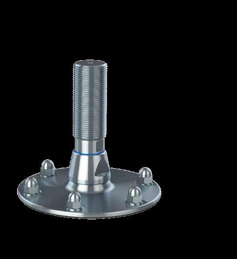
Fully-threaded seismic levelling feet - HXJE (L)
The design and patent protected seismic HXJE (L) levelling foot is the optimal choice for all machinery, equipment, tanks and vessels located in areas subject to earthquakes and at the same time need to benefit from a long levelling range.
- Simple and fast installation with height-adjustable compact design
- Adjustment through flat at the bottom of spindle
- Movable set-up - no concrete molding required
- Total seismic stability through bolted fastening and patented locking mechanism
- Verified through Finite Element Analysis (FEA) and calculated according to New Zealand seismic standard (NZS 4219)
- Calculated according to New Zealand seismic standard NZS 4219
- Seismic anchors chosen and approved by our experienced partner Hilti
- Stainless steel AISI 304/A2, 1.4301. Optional AISI 316/A4, 1.4401
Fully-threaded seismic levelling feet - HXJE (L)
100 100 100 Ø E D1 B L4 L MIN L1 MAX L5 C LE M56 151 118 314 199 188.000 11800 HXE(L)56200 M56 216 118 379 199 188.000 8000 HXE(L)56260 M64 150 118 319 206 236.000 17800 HXE(L)64200 M64 210 118 379 206 236.000 12500 HXE(L)64260 M72 193 129 380 223 327.000 22200 HXE(L)72250 M72 251 129 438 223 327.000 16300 HXE(L)72310 M80 187 129 380 234 432.000 30800 HXE(L)80250 M80 145 129 438 234 432.000 22600 HXE(L)80310 M90 179 129 380 241 432.000 50500 HXE(L)90250 M90 237 129 438 241 432.000 37100 HXE(L)90310 250 249 22 3 M16x240 101 63000 HXJE250(L) 300 299 19 4 M20x250 121 82000 HXJE300(L) 350 349 18 6 M20x250 142 90.000 HXJE350(L) 400 399 17 6 M24x330 166 126000 HXJE400(L)
SPINDLE FOOT PLATE *L MIN is calculated without use of nut on spindle PRODUCT CODE FOOT - SPINDLE EXAMPLE HXJE300(L)-HXE80250 TYPE DIAMETER Ø [mm] HEIGHT B [mm] HOLES [PSC] BOLT TYPE [SIZE] POSITION E [mm] NOM. PULL TENSION [N] ITEM CODE THREAD HEIGHT L1 [mm] HEIGHT L4 [mm] HEIGHT L5 [mm] L MIN* [mm] NOM LOAD COMPRESSION [N] MAX HORISONTAL LOAD SHEAR [N] ITEM CODE
18 17
Fully-threaded seismic levelling feet - HXJCFE (S)
The design and patent protected seismic HXJCFE (S) levelling foot is the optimal choice for all machinery, equipment, tanks and vessels located in areas subject to earthquakes and at the same time need to benefit from a long levelling range.
- Anchors decentered at one side of the spindle
- Easier installation when machine restricts access to all sides of the footplate
- Lower seismic performance than round footplate
- Available in one size for small and one size for large
- Simple and fast installation with height-adjustable compact design
- Adjustment through flat at the bottom of spindle
- Movable set-up - no concrete molding required
- Total seismic stability through bolted fastening and patented locking mechanism
- Verified through Finite Element Analysis (FEA) and calculated according to New Zealand seismic standard (NZS 4219)
- Calculated according to New Zealand seismic standard NZS 4219
- Seismic anchors chosen and approved by our experienced partner Hilti
- Stainless steel AISI 304/A2, 1.4301. Optional AISI 316/A4, 1.4401
Fully-threaded seismic levelling feet - HXJCFE (S)
*L MIN is calculated without use of nut on spindle
100 100 100 L4 B L1 L MIN C MAX L5 A W a1 a2 b1 b2 M30 116 77 228 105 60.000 2100 HXE(s)30150 M30 178 77 288 105 60.000 1300 HXE(S)30210 M36 114 77 221 105 96.000 3500 HXE(S)36150 M36 179 77 288 105 96.000 2200 HXE(S)36210 M42 118 82 233 110 140.000 4900 HXE(S)42150 M42 179 82 298 110 140.000 3200 HXE(S)42210 M48 143 82 283 120 140.000 6900 HXE(S)48200 M48 203 82 343 120 140.000 4800 HXE(S)48260 M56 138 82 278 120 140.000 13100 HXE(S)56200 M56 203 82 343 120 140.000 8900 HXE(S)56260 150 150X250 15 4 M12x155 60X104 : 143x64 17000 HXJCFE150(s)
SPINDLE
PRODUCT CODE FOOT - SPINDLE EXAMPLE HXJCFE300(I)-HXE72250 TYPE DIAMETER Ø [mm] HEIGHT B [mm] HOLES [PSC] BOLT TYPE POSITION E [mm] NOM. PULL TENSION (N) ITEM CODE THREAD HEIGHT L1 [mm] HEIGHT L4 [mm] HEIGHT L5 [mm] L MIN* [mm] NOM LOAD [N] MAX HORISONTAL LOAD SHEAR [N] ITEM CODE
FOOT PLATE
20 19
Fully-threaded seismic levelling feet - HXJCFE (L)
The design and patent protected seismic HXJCFE (L) levelling foot is the optimal choice for all machinery, equipment, tanks and vessels located in areas subject to earthquakes and at the same time need to benefit from a long levelling range.
- Anchors decentered at one side of the spindle
- Easier installation when machine restricts access to all sides of the footplate
- Lower seismic performance than round footplate
- Available in one size for small and one size for large
- Simple and fast installation with height-adjustable compact design
- Adjustment through flat at the bottom of spindle
- Movable set-up - no concrete molding required
- Total seismic stability through bolted fastening and patented locking mechanism
- Verified through Finite Element Analysis (FEA) and calculated according to New Zealand seismic standard (NZS 4219)
- Calculated according to New Zealand seismic standard NZS 4219
- Seismic anchors chosen and approved by our experienced partner Hilti
- Stainless steel AISI 304/A2, 1.4301. Optional AISI 316/A4, 1.4401
Fully-threaded seismic levelling feet - HXJCFE (L)
100 100 100 L4 B L1 L MIN C MAX L5 A W a1 a2 b1 b2 M56 138 82 278 120 140.000 13100 HXE(S)56200 M56 203 82 343 120 140.000 8900 HXE(S)56260 M64 143 118 319 156 236.000 17800 HXE(L)64260 M64 203 118 379 156 236.000 12500 HXE(L)64260 M72 166 129 380 170 327.000 22200 HXE(L)72250 M72 226 129 438 170 327.000 16300 HXE(L)72310 M80 166 129 380 170 432.000 30800 HXE(L)80250 M80 226 129 438 170 432.000 22600 HXE(L)80310 M90 166 129 380 170 432.000 50500 HXE(L)90250 M90 226 129 438 170 432.000 37100 HXE(L)90310 300 300X400 15 4 M16x240 86x214:200x120 30000 HXJCFE300(I)
SPINDLE
PRODUCT CODE FOOT - SPINDLE EXAMPLE HXJCFE300(I)-HXE72250 *L MIN is calculated without use of nut on spindle TYPE DIAMETER Ø [mm] HEIGHT B [mm] HOLES [PSC] BOLT TYPE POSITION E NOM. PULL (TENSION) ITEM CODE THREAD HEIGHT L1 [mm] HEIGHT L4 [mm] HEIGHT L5 [mm] L MIN [mm] NOM LOAD [N] MAX HORISONTAL LOAD SHEAR [N] ITEM CODE
FOOT PLATE
22 21
Cleaning & Maintenance
Seismic levelling feet
CLEANING
1. Rinse with water (maximum temperature ~40°C on proteins).
2. Distribute and cover all surfaces with foaming alkaline detergent for minimum 10 minutes. All standard products within the industry can be used. Follow supplier recommendations for temperature (maximum 100°C) and concentration depending on foaming detergent.
3. Rinse with hot water (maximum 100°C) with lowmedium pressure (approximately 8-12 bar) until it is visibly clean. Cleaning of the levelling foot including sealings and dome-headed nuts can normally be done with a spraying nozzle pointing in a downwards direction approximately 45°. For heavy duty cleaning a more direct-oriented nozzle can be necessary. Be careful not to damage the sealings if high pressure cleaning is used. Keep nozzle at minimum 200-300 mm distance.
4. Mechanical cleaning may be necessary if the levelling foot is severely soiled. Cleaning must be executed with a soft brush or soft plastic scraper together with a more direct pointing nozzle spray. Steel scraper, steel brush or other sharp metallic tools are strictly prohibited, since the sealings can be severely damaged and the steel surfaces will be scratched.
MAINTENANCE
1. If the sealings on the sleeve are damaged they must be replaced. Always use genuine spare parts from NGI.
2. If the sealing between the foot and the spindle is damaged, replace the whole levelling foot and install a new one. An assembled levelling foot cannot be separated.
3. Load on the levelling foot must be obtained in order for the footplate to be hygienically sealed to the floor.
4. For a levelling foot for floor fixing always make sure that the floor fixing nut or bolt is tightened as specified in the installation manual. Tighten if necessary. If replacement of nuts or washers is always use genuine spare parts from NGI.
5. If any readjustments are necessary the levelling foot and the nearest surroundings must be cleaned carefully to prevent any soil from entering the sleeve.

BEST PRACTICE
Position machine to neighboring machine first. Start with the feet closest to neighbor machine. Level with a laser measurement device.
Keep machine supports (crane, jack, forklift) near to machine throughout the levelling process for fast response to sudden unexpected events. Ensure that machine never tilts during installation.
If using more than 3 levelling feet, make sure that all feet carry weight.
Try turning the foot to check if foot is supporting weight.
Clean the feet and the floor before feet are lowered to the floor.
DO NOT
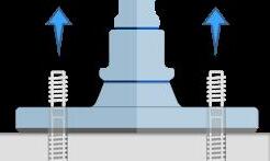
Do not fasten the levelling feet to the floor until it is fully levelled.
Do not lift the machine after it is fastened to the floor.
 STAINLESS STEEL
SILICONE SEAL
SILICONE SEAL
SILICONE SEAL
ANTI-SLIP RUBBER
STAINLESS STEEL
STAINLESS STEEL
STAINLESS STEEL
SILICONE SEAL
SILICONE SEAL
SILICONE SEAL
ANTI-SLIP RUBBER
STAINLESS STEEL
minimum
Read
example one of our reference cases at our website, where GIG KARASEK has used NGI seismic levelling feet for one of their production sites. 24 23
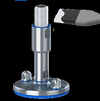
The design and patent protected NGI Seismic levelling feet is the only hygienic seismic levelling feet in the world designed and calculated according to the international New Zealand seismic standard. The feet have self-draining surfaces, sealed movable parts and no exposed thread which secures
absolute
cleaning and maximum product safety.
for
Installation
Seismic levelling feet
It is important to follow these instructions in order to ensure the certified hygienic design and functionality. This documentation is enclosed with the levelling feet and should always be handed over to the end-user.
Preparations prior to installation
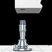
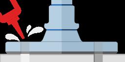
A. Prior to installation of the seismic levelling foot ensure that the foot does not exceed the slope of the floor.
B. When installing, make sure that the footplate does not span over cracks, grout lines or other floor imperfections. If unavoidable, seal the cavity with bonding material under and around the edge of the footplate. Remove any dirt or grease from under the footplate.
C. Lift the machine with adequate machinery (e.g. jack, forklift, crane) so that seismic levelling feet can be screwed into its intended position on machine. Screw the thread into the machine until the levelling foot is in its estimated position or in the middle of the adjustment range, lower the machine down and check whether it is levelled.
Level the machine by lifting the leg with a jack and adjust the foot to the new position. The turning of the thread is not meant to lift the machine, but only to fine-tune the height. When the machine is levelled and its location is correct, check mark feet location on the floor. See next page how to mark and drill holes.
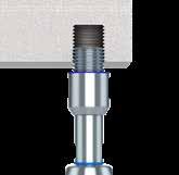
D. Make sure that the sealing is correctly fixed on top of the sleeve. Grease the exposed thread with FoodLube Universal Grease and make sure to remove any excess grease after installation.
E. Ensure minimum engagement within the machine frame. The minimum engagement (LE) must not be smaller than the spindle diameter. Use a wrench to adjust the vertical position and make sure that the engagement is no less than the diameter of the thread.
During mounting, support weight of seismic levelling foot with suitable tools (e g jack), if needed. Larger sizes of seismic levelling feet can weigh up to 40 kg.
Installation Seismic levelling feet
It is important to follow these instructions in order to ensure the certified hygienic design and functionality. This documentation is enclosed with the levelling feet and should always be handed over to the end-user.
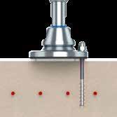
Marking of position
1. MARK HOLES OF FOOTPLATE with dimensions outlined in footplate dimensions. Use this method with caution, as tolerances in machines might add up and assumed position of holes might not fit afterwards. Alternatively, you can mark the holes through the footplate. When the machine is positioned at its final installation location, mark all holes through the footplates of all seismic levelling feet. Ensure that holes are visibly marked on the floor.
Drilling holes with a drill template can be risky when several seismic feet are used. Tolerances in the machine might add up so that drilled holes might not suit anymore. It is recommended to use the machine as a template for marking holes.
2. REMOVE THE MACHINE from the installation location so that all marked drilling spots are visible and easily accessible. Use appropriate machine to lift machine.
Drilling
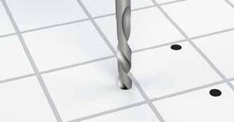
3. DRILL & CLEAN HOLES:
Through-setting: Drill hole through the clearance holes in the footplate to the required drilling depth with a hammer drill set in rotation-hammer mode using an appropriately sized carbide drill bit. Through-setting is only allowed for HIT-Z-R anchors. HIT-Z-R anchors do not require cleaning to perform according to seismic standards.
Pre-setting: Drill holes at the marked spots to the required drilling depth with a hammer drill set in rotation-hammer mode using an appropriately sized carbide drill bit. For dust free drilling use the SAFEsetTM drill bit by Hilti. Clean holes from any noticeable dust.
4. CHECK SETTING DEPTH: Mark the anchor for the required drilling depth. Compress the drilling dust as the anchor is fit into the hole until the marked depth. If it is not possible to compress the dust, remove the dust in the drill hole or drill deeper. Using Hilti equipment: When drilling with non-cleaning drill sets, the required drilling depths can vary due to accumulation of dust in the hole.
The helixed part of HIT Z R anchors must always be fully inserted into the ground Generally, ensure that sufficient length of thread B+f see FOOTPLATE DIMENSIONS) is above ground and insert remaining length of anchor into the ground. Drilling depths are different for cleaned holes and uncleaned holes. Check for correct drilling depths under FOOTPLATE DIMENSIONS.

Minimum engagement (LE) LE Ø LE = Ø Maximum distance above ground A. C. D. E. B. 1. 2. 3. 4.
26 25
Installation Seismic levelling feet
It is important to follow these instructions in order to ensure the certified hygienic design and functionality. This documentation is enclosed with the levelling feet and should always be handed over to the end-user.
Levelling & fastening
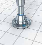
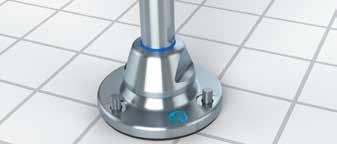
5. PLACE THE MACHINE: Move the machine back to the final installation location so that holes on the floor match with holes in the footplate.
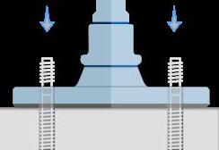
6. FIXATE THE MACHINE: Fixate the position of the machine by putting two anchors through the footplates and into the holes of all seismic levelling feet.
Do not use mortar at this point!
7. LEVEL & LOCK: The levelling process can be divided into two steps:
a) Height adjustment and b) Fine adjustment / levelling of weight.
Whereas step a) refers to the rough adjustment of height with levelling ranges of >2mm, step b) deals with the fine adjustment of a few millimeters.
8. ROUGH HEIGHT ADJUSTMENT >2MM: Adjust and level machine by turning the spindle clockwise or anticlockwise. Ensure that machine is fully levelled in height and angle before any mortar is used.
1. Ensure that all footplates rest on floor and carry weight (see description above).
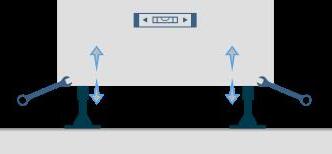
2. Check levelling of machine with suitable device (e.g. laser measuring device, spirit level).
3. Fine tune the height of the machine by turning the spindle clockwise for lowering or anti-clockwise for elevating.
4. Repeat steps 1 to 3 until fully levelled.
Always lift machine to undertake rough height adjustment of spindles. Generally, this applies to adjustments of more than 2mm in height.
9. FINE ADJUSTMENT / LEVELLING OF WEIGHT: Ensure that the weight of machine is equally distributed on all levelling feet. This can be done by attempting to lift the machine by turning the spindle minimally. All feet should require the same torque to do this. This step requires to “feel” the required torque to lift the machine by turning the spindle.
1. Ensure that all footplates rest on floor and carry weight (see description above).
2. Check levelling of machine with suitable device (e.g. laser measuring device, spirit level).
3. Fine tune the height of the machine by turning the spindle clockwise for lowering or anti-clockwise for elevating.
4. Repeat steps 1 to 3 until fully levelled

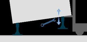
The turning of the thread now is not meant to lift the machine, but only to fine-tune the height. Do not level machine under full weight.
Lower machine by clockwise turning, elevate machine by anticlockwise turning.
Installation Seismic levelling feet
It is important to follow these instructions in order to ensure the certified hygienic design and functionality. This documentation is enclosed with the levelling feet and should always be handed over to the end-user.
Locking of spindle to the footplate and machine
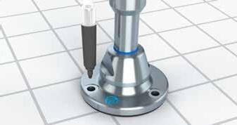
10. LOCK THE SPINDLE TO THE FOOTPLATE: Lock the spindle to the footplate by turning the top nut clockwise with required torque.
Locking the top nut increases the strength of the seismic levelling foot to obtain highest possible safety against bending. As it is not possible to guarantee a complete locking of spindle to footplate and thus, movement during earthquakes, a freely moving joint is assumed Any locking of the top nut therefore increases the strength of the seismic levelling foot
11. LOCK SLEEVE OR COUNTER NUT TO MACHINE Turn the sleeve anti-clockwise up to its highest position to cover the thread in between machine and sleeve. The sleeve is not designed to carry any weight. It is used to fulfill hygienic requirements and to act as a counter nut to the machine.
Always ensure that the sleeve can cover the whole length of the thread. If not, the minimum level of engagement is not met and the strength of the levelling foot is not guaranteed.
6. 5. 8. 9. 10. 11.
28 27
Installation Seismic levelling feet
It is important to follow these instructions in order to ensure the certified hygienic design and functionality. This documentation is enclosed with the levelling feet and should always be handed over to the end-user.
Fasten the foot to the floor
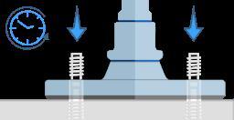
12. REMOVE FIXATING ANCHORS: Remove any lose anchors that were put into place during step 11.
13. INJECT MORTAR: Inject adhesive from the ground of the borehole without forming air voids, starting at the bottom of the hole, slowly withdrawing the mixer with each trigger pull.
As a rule of thumb, fill holes 50% with mortar for through setting, or as required to ensure that the annular gap between the anchor and the concrete is completely filled with adhesive along the embedment length. Fill up the holes of the footplate with mortar to add additional stability.
Find the required amount of mortar in the footplate datasheet or in table 3.
14. INSTALL ANCHOR: Install anchor through positioned footplate. Remove any excess mortar on the top side of the footplate. Ensure that anchors are installed before mortar’s working time t,work has elapsed, see table 1. It is recommended to install all anchors of one footplate before moving on to other levelling feet to avoid hardening of mortar before all anchors are installed. If anchors are too long, cut off excessive length with appropriate tooling.
Install anchors only when machine is fully levelled. Once anchors are installed, horizontal adjustment of machine is limited to very small changes. If major height adjustments are needed, lift machine with caution to not damage the already dried up mortar. Then, repeat procedure outlined in step 3a and 3b.
Damage to dried mortar can result in complete loss of seismic strength of the anchors.
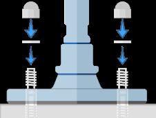
15. FASTEN FOOT: After curing time t,cure has elapsed, see table 1, use the washer and dome-headed nut to fasten the seismic levelling foot to the floor. Set washers (DIN 125A) and dome headed nuts (DIN 1587) at the anchor rod and tighten them with the maximum tightening torque according to table 3.
Installation steps Seismic levelling feet
The installation of the seismic levelling foot can be done through either one of the following three methods. Detailed descriptions of the steps can be found in the installation manual at the previous pages.
12. 14. 8. 8. 13. 15.
METHOD TASK STEP THROUGH FIXING DRILLING WITH TEMPLATE USE MACHINE AS TEMPLATE When all sides of the seismic levelling foot can be reached with a drilling machine, while feet are installed on machine. When the exact position of the feet is known and holes can be drilled prior to machine installation. Levelling foot are not reachable with a drilling machine when feet are installed on machine or final position of machine needs to be determined during installation. MARK Mark holes 1. Remove the machine 2. DRILLLING AND LEVELLING Drill & clean holes 3. Check setting depth 4. Place the machine 5. Fixate the machine 6. LOCKING OF SPINDLE Rough height adjustment 8. Fine adjustment / levelling of weight 9. Lock spindle to the footplate 10. Lock sleeve or counter nut to machine 11. FASTEN THE FOOT TO F THE LOOR Remove the fixating anchors 12. Inject the motar 13. Install the anchor 14. Fasten the foot 15.
30 29
Seismic levelling feet
**Includes filling up the annular gap in the footplate for providing additional horizontal stability. *These values are only valid as guidelines, not exact values due to the geometry of the counter nut.
Exact tightening values cannot be determined, therefore calculation of the seismic foot assume the worst case that the counter nut is loose during an earthquake.
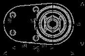
Footplate dimensions
Seismic levelling feet - small
All dimensions for standard footplate sizes for SMALL footplates.
HXJCFE FOOTPLATE XHJSE FOOTPLATE INSTALLATION DIMENSIONS
HXJCFE Footplate XHJSE Footplate Installation dimensions

1) GENERAL (all footplates) 1.1 Mortar HIT-HY 200 1.2 Proof of calcu at on Design method ACI 318-08 / Chem
nstallat on method Hammer drilled hole, Installation cond tion: Dry 1.4 Base material (Concrete qua ity) Cracked concrete, C20/25, fc = 2901 psi; Temp short/long: 40/24 °C An
2) DIMENSIONS [mm]
3) ANCHORS
4) TENSION CAPACITY FT 4.1 Max Tens on (FH1|FT1) [kN] 4 | -17
Note: Tension capacity only shown up to FH=30kN, as largest possible spindle to combine with is limited to 30kN.
concrete
ty can
s HXJCFE150(S)
d
1.3
mp oved
qua
great y mp ove the performance of the used ancho
XHJE150(S) XHJE200(S) XHJE250(S) a b c
2.1 Dimens ons bxa or Ø 150x250 150 200 250 2.2 Pos tion a1xb1 a2xb2 or E 60x104; 143x64 60 80 101 2.3 Thickness footplate B 15 20 20 20 2.4 Height nut & washer f 12.5 10 12.5 16 2.5 Sett ng depth h 125 120 120 170 2.6 Concrete depth 1 h1 185 180 180 270 2.7 Concrete depth 2 h2 155 150 150 200
3.1 Amount - 4 3 4 4 3.2 Type - HIT-Z-R HIT-Z-R HIT-Z-R HIT-Z-R 3.3 Thread size x Length [mm] M12x155 M10x160 M12x155 M16x205 3.4 Drill diameter [mm] 14 12 14 18 3.5 T ghtening torque [Nm] 40 25 40 80 3.6 Mortar per footplate [ml] 68 42 68 128
13
-28 12 | -38 14 | -61 4.2 Reduced Tension (FH2|FT2) [kN] 15 | -11 30 | -13 30 | -30 30 | -55 4.3 No Tens on (FH3|FT3) [kN] 22 | 0 - -a b c d -70kN -60kN -50kN -40kN -30kN -20kN -10kN kN kN 5kN 10kN 15kN 20kN 25kN 30kN V e r t i c a l F o r c e T e n s i o n c a p a c i t y F T
|
Horizontal Load, FH
FT
Tables
32 31
Footplate dimensions
Seismic levelling feet - large
Installation Disclaimer
Where do seismic design values come from?
Seismic design values are gathered from several sources. The United States Geological Survey (USGS) (www.usgs.gov) lists up seismic design values from around the world. Furthermore, national standards such as the NZS 4219 contain country specific seismic design values which are also taken into consideration. Lastly, the United Facility Criteria (UFC) has compiled a list of seismic design values specifically for the USA and other locations around the world.
Why does NGI use NZS 4219 and IBC 2009 instead of national standards?
NGI uses the New Zealand Standard 4219:2006 (NZS) and International Building Code 2009 (IBC) for various reasons: First, NGI has compared several national earthquake standards from around the world and has concluded that resulting forces of these standards largely depend on many assumptions made for the calculation of occurring forces during an earthquake. Although these assumptions are expressed with different words and different levels of detail, they all result in similar forces when similar sounding assumptions are made. The NZS4219 was found to be the most accessible and most comprehensible national code for estimating forces during an earthquake. Second, the IBC is used to extend seismic design values for seismic regions around the world. The IBC calls these values “seismic ground motion values”. Third, NGI’s core expertise lies in the design and engineering of levelling feet. The NZS and IBC are used to recommend suitable levelling feet for seismic areas. Therefore, NGI can give a quantitative estimation of seismic forces to be expected in a given location under certain assumptions. In any case, national standard codes need to be followed for any machinery delivered into seismic areas. NGI’s calculations are to be understood as an estimation of forces which are not legally binding and need always be verified by the customer.
Where can I find the exact values and codes used in the seismic calculation?
Is my machine seismic certified when I use NGI seismic levelling feet?
NGI seismic levelling feet are designed to fasten machinery and equipment safely to the ground in case of additionally occurring forces. This can happen during earthquakes, wind loads or any other expected or unexpected horizontal and vertical loads. NGI seismic levelling feet are able to compensate forces up to a given maximum limit, as outlined in the corresponding datasheet and only when installed as described in the installation manual. NGI cannot take responsibility for any other component that is directly or indirectly attached to NGI’s seismic levelling feet. It is the machine builder’s responsibility to ensure that the machine as a whole is seismic certified according to the respective national seismic standard.
Can NGI also calculate forces for machines with complex geometries?
NGI calculates forces according to a static model in which forces can occur either directly at the feet or at the machine’s center of gravity. NGI offers this service for all customers when the machine’s geometry allows a simplification of the model. In cases when the geometry is perceived to be too complex (e.g. the center of gravity is almost above the furthest levelling foot) or not suitable for simplification, NGI reserves the right to ask the customer for a calculation of forces. In any case, calculations undertaken by NGI always need to be verified by the customer and do not replace a detailed seismic calculation or simulation of the machine.
Do I need to use the recommended HILTI anchors? NGI’s seismic levelling feet are designed to be installed with HIT V or HIT Z anchors by HILTI as outlined in the respective datasheet. The recommended anchors guarantee that NGI’s seismic levelling feet can sustain the combination of vertical pull forces and horizontal shear forces. If seismic levelling feet are used in combination with any other anchors than the recommended ones, the strength of the seismic feet cannot be guaranteed and must be calculated by the customer. 1)
The NZS and IBC are both freely available on the internet. NGI uses a simplified version of the formulas used in the NZS that is tailored towards bottom restrained equipment. This is to simplify the selection process of assumptions for the customer. Any values resulting from these assumptions are rounded up to the next reasonable integer and serves as an increased safety factor for seismic calculations.
HXJCFE FOOTPLATE XHJSE FOOTPLATE INSTALLATION DIMENSIONS
GENERAL (all footplates) 1.1 Mortar HIT-HY 200 1.2 Proof of calcu at on Design method ACI 318-08 / Chem 1.3 Installation method Hammer drilled hole, Installat on cond tion: Dry 1.4 Base material (Concrete qua ity) Cracked concrete, C20/25, fc = 2901 psi; Temp short/ ong: 40/24 °C An mp oved concrete qua ty can great y mp ove the performance of the used anchors HXJCFE300(L) XHJE250(L) XHJE300(L) XHJE350(L) XHJE400(L) a b c d e 2) DIMENSIONS [mm] 2.1 Dimension bxa or Ø 300x400 250 300 350 400 2.2 Posit on a1xb1; a2xb2 or E 86x216; 200x120 101 121 142 166 2.3 Thickness footplate B 15 20 20 20 20 2.4 Height nut & washer f 19 16 19 19 23 2.5 Setting depth h 190 190 210 210 285 2.6 Concrete depth 1 h1 290 290 310 310 385 2.7 Concrete depth 2 h2 250 250 270 270 345
3.1 Amount - 4 3 4 6 6 3.2 Type - HIT-Z-R HIT-Z-R HIT-Z-R HIT-Z-R H T-V-R 3.3 Thread size x Length [mm] M16x240 M16x240 M20x250 M20x250 M24x330 3.4 Drill d ameter [mm] 18 18 22 22 28 3.5 Tightening torque [Nm] 80 80 150 150 200 3.6 Mortar per footplate [m ] 140 105 212 318 738 4) TENSION CAPACITY FT 4.1 Max Tension (FH1|FT1) [kN] 14 | -39 14 | -63 28 | -82 41 | -90 58 | -126 4.2 Reduced Tension (FH2|FT2) [kN] 48 | -20 60 | -22 100 | -47 100 | -70 100 | -110 4.3 No Tension (FH3|FT3) [kN] 58 | 0 66 | 0 - -a b c d e -150kN -125kN -100kN -75kN -50kN -25kN kN kN 20kN 40kN 60kN 80kN 100kN Ve r t i ca l L o a d, Tens i o n ca p a c i t y , FT Horizontal Load, FH HXJCFE
XHJSE
Installation dimensions All dimensions for standard footplate sizes for LARGE footplates. FT
3) ANCHORS
Footplate
Footplate
34 33
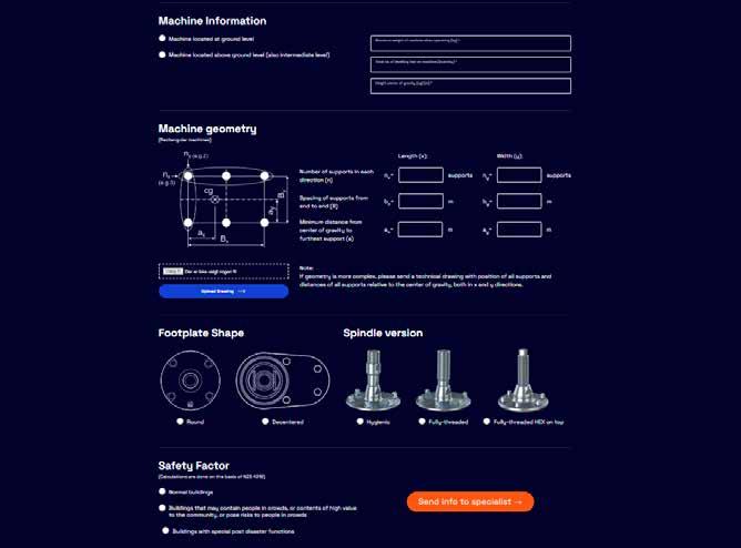
We highly recommend that you contact our specialists to make sure you choose the right seismic levelling feet for your project! At our website we have a configurator where you can fill in the requirements for your project. Afterwards the form will be sent to our seismic levelling feet specialist.
Find our configurator by scanning the below QR code and fill out the necessary information.
Based on your input, our seismic specialist will contact you regarding a non-binding solution for your seismic project.
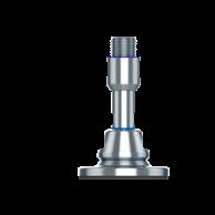
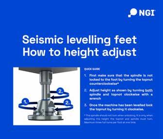
1. First make sure that the spindle is not locked to the foot by turning the topnut counterclockwise*
2. Adjust height as shown by turning both spindle and topnot clockwise with a wrench
3. Once the machine has been levelled lock the topnut by turning it clockwise.
QUICK GUIDE OF HOW TO ADJUST SEISMIC FEET:
The spindle should not turn when unlocking. It is only when adjusting the height the topnot and spindle must turn. Maximum three full turns per foot at one time. 1. 2. 2.
short
showing how to height adjust our seismic levelling feet.
a quick guide below.
*
Visit our channel at Vimeo and see a
video
Also find
See video here Find Seismic configurator here
Height
Seismic Configurator online Make sure you choose the right seismic levelling foot
adjustments Seismic levelling feet
36 35
Accessories - HILTI tools Accessories - HILTI tools
Hilti’s seismic research includes detailed investigation of product performance under simulated seismic conditions and full scale system testing.
This multilevel approach helps to capture the complexity of fastening systems behavior under seismic conditions. Earthquakes can affect a wide range of construction products that Hilti supplies anchors for and NGI are confident that they are the best on the market today.
Hilti is pioneering research to extensively test systems for earthquake performance in order to support their customers with recommendations for design applications.


TE-CX 12/22 12X220 150 M10 TE-CX 14/22 14X220 150 M12 TE-CX 18/32 18X320 250 M16
TE-CX 22/48 22X480 410 M20
TE-CX 28/48 28X480 410 M24

TE-CD 12/33 12X330
14/37 14X370
TE-CD 18/37 18X370
HXJCFE150(S)/ XHJCFE150(S) M12x155 HIT-Z-R 4
HXJE150(S)/ XHJSE150(S) M10x160 HIT-Z-R 3
HXJE200(S)/ XHJSE200(S) M12x155 HIT-Z-R 4
HXJE250(S)/ XHJSE250(S) M16x250 HIT-Z-R 4
HXJCFE300(L)/ XHJCFE300(L) M16x240 HIT-Z-R
XHJSE250(L)
XHJSE300(L) M20x250
HXJE350(L)/ XHJSE350(L) M20x250
240
240
400 M20 TE-YD
400
240 M10 TE-CD
M12
M16 TE-YD 22/59 22X590
28/59 28X590
M24
HIT-Z-R-4M12
HIT-Z-R-3M10
HIT-Z-R-4M12
HIT-Z-R-4M16
4 HIT-Z-R-4M16 HXJE250(L)/
M16x240 HIT-Z-R 3 HIT-Z-R-3M16 HXJE300(L)/
HIT-Z-R
HIT-Z-R-4M20
4
HIT-Z-R-6M20
HIT-Z-R 6
HIT-V-R
HIT-V-R-6M24
HXJE400(L)/XHJSE400(L) M24x330
6
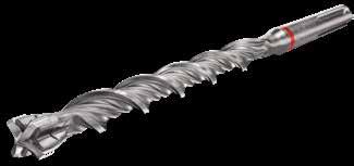
MORTAR STANDARD DRILL
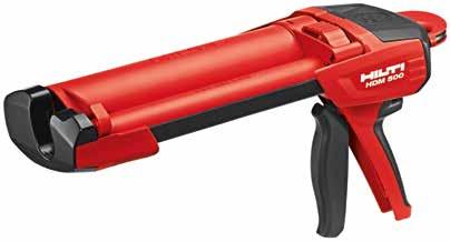
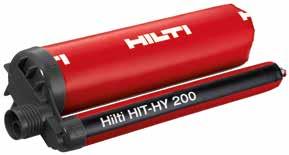
SAFE-SET DRILL BIT INSTALLATION PACK SMALL LARGE HILTI ITEM CODE DESCRIPTION ITEM CODE Kit HDM 500 Injectable mortar dispenser KitHDM500 Kit HDM 500-A22 Cordless electric dispenser KitHDE500-A22 HILTI ITEM CODE DESCRIPTION AMOUNT ITEM CODE HIT-HY-200-A Injectable mortar 330ml HIT-HY-200-A HILTI ITEM CODE DIMENSIONS WORKING LENGTH USE FOR HILTI ITEM CODE DIMENSIONS WORKING LENGTH USE FOR FOOTPLATE ANCHOR SIZE [Metric] BOLT TYPE QTY. ANCHORS, DOME-HEADED NUTS & WASHERS ITEM CODE
PISTOL
BIT
38 37
Accessories - anchors Accessories - anchors
High-performance anchor rod for injectable hybrid/epoxy anchors (A4 stainless steel).
• Material, corrosion: Stainless steel, A4
• Base materials: Concrete (cracked), Concrete (uncracked), Masonry (solid)
• PROFIS software: Yes

M10x160 12 M10 160 120 25 13 HITZRM10x160 M12x155 14 M12 155 120 40 18 HITZRM12x155 M16x205 18 M16 205 170 80 32 HITZRM16x250 M16x240 18 M16 240 190 80 35 HITZRM16x240 M20x250 22 M20 250 210 150 53 HITZRM20x250 M24x330 26 M24 330 285 200 123 HITVRM24x300
ANCHOR HIT-Z-R ANCHOR HIT-V-R TYPE DRILL DIAMETER DD [mm] THREAD SIZE TS [MM] LENGTH L [MM] SETTING DEPTH (SD) [MM] TIGHTENING TORQUE F [NM] REQUIRED MORTARPER ANCHOR [ML] ITEM CODE TYPE DRILL DIAMETER DD [mm] THREAD SIZE TS [MM] LENGTH L [MM] SETTING DEPTH (SD) [MM] TIGHTENING TORQUE F [NM] REQUIRED MORTARPER ANCHOR [ML] ITEM CODE
40 39
Accessories for levelling feet - dome-headed nuts
Accessories for levelling feet - dome-headed nuts

Our seismic levelling feet can alternatively be supplied with certified hygienic bolts and nuts. More bolt lengths are available.
Find the relevant assortment of bolts and nuts for seismic levelling feet at our website or in our catalogue.
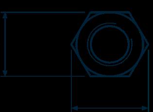
W A M10 DIN 1587 A2 17 8 17 18,90 DIN1587A2M10 M12 DIN 1587 A2 19 10 19 21,10 DIN1587A2M12 M16 DIN 1587 A2 24 13 24 26,75 DIN1587A2M16 M20 DIN 1587 A2 34 16 30 33,53 DIN1587A2M20 M24 DIN 1587 A2 42 19 36 39,98 DIN1587A2M24
THREAD DIN NORM TOTAL HEIGHT B1 [mm] WRENCH HEIGHT B2 [mm] W [mm] OUTER DIAMETER A [mm] ITEM CODE
- Stainless steel AISI 304/A2, 1.4301 - Standard dome-headed nuts (DIN 1587 A2) - All dimensions available DOME-HEADED NUTS DIN 1587 A2
42 41
Accessories - NGI wrenches
XHJSE machine feet need three different wrenches for installation.
NGI wrenches are laser cut and designed to fit NGI machine feet.
Please check the selection guide to see which sizes are needed for your respective model.
• W1: Spindle
• W2: Sleeve
• W3: Counter nut
Accessories - NGI wrenches


M30 22 36 50 M36 27 41 50 M42 32 50 55 M48 36 55 60 M65S/M56L 41 65 85 M64 50 75 85 M72 55 80 95 M80 65 90 95 M90 75 100 95 22 195 10 46 WR22 27 240 10 56 WR27 32 274 10 67 WR32 36 303 10 74 WR36 41 343 10 85 WR41 50 413 10 102 WR50 55 457 10 113 WR55 60 492 10 122 WR60 65 528 10 132 WR65 75 608 10 152 WR75 80 644 10 162 WR80 85 690 10 174 WR85 90 690 10 174 WR90 95 850 10 195 WR95 100 1000 10 195 WR100
SELECTION GUIDE NGI WRENCHES W [mm] LENGTH L [mm] THICKNESS C [mm] HEAD WIDTH B [mm] ITEM CODE SPINDLE SIZE W1 [mm] W2 [mm] W3 [mm]
44 43
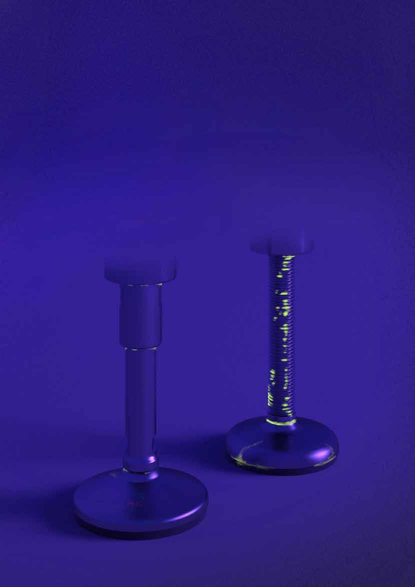
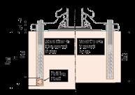
UV lighting used to expose bacteria
• THE CERTIFIED HYGIENIC LEVELLING FOOT IS CLEAN
• THE SPINDLE OR THE FULLY-THREADED LEVELLING FOOT IS INFECTED WITH BACTERIA
• FULLY-THREADED VS HYGIENIC - IT TAKES 28% MORE RESSOURCES TO REACH THE SAME LEVEL OF CLEANABILITY ON A FULLY-THREADED FOOT
• RESSOURCES COULD BE TIME, WATER, MONEY, DETERGENTS, ETC.


Technical specifications Cleaning Instructions
The resources required to clean NGI’s levelling feet depends largely on the design of the levelling foot and the environment in which the levelling foot is used.
It is possible to use all known detergents to clean the levelling feet as long as the instructions provided by the supplier is complied with.
ESTIMATED SAVINGS 28%
FULLY-THREADED CERTIFIED HYGIENIC
PRODUCT GROUP CLEANING WASH DOWN TEST CLINICAL CLEAN HYGIENIC CLEAN REGULAR CLEAN CLINICAL CLEAN REGULAR CLEAN 3A, USDA & EHEDG 3A, USDA & EHEDG SAVINGS HYGIENIC * REFERENCE PLATE FULLY-THREADED STANDARD PLASTIC FULLY-THREADED SOLID FULLY THREADED * Reference plate = Stainless steel plate with surface less than Ra 0,8 LOW MEDIUM HIGH RESOURCES (TIME, WATER, DETERGENTS)
(TIME, WATER, DETERGENTS)
RESOURCES
46 45

NGI Innovation - the Sustainable Way
Stainless steel - Recyclable materials
80% of our products can be recycled. We are working on initiatives to make this percentage even higher.
Product Innovation
Hygienic seals - Resource saving
Permit easy cleaning and reduce water consumption.
High Quality - Longer lifetime
Our products are very high quality which means they have a longer lifetime than corresponding components.
Innovating for tomorrow
Investing in research & development
Hygienic design - Protecting consumers
We make sure that the components do not constitute a hygiene risk through innovative and uncompromising design.
48 47
1-4 DAYS DELIVERY IN SCANDINAVIA
1-4 DAYS DELIVERY IN SCANDINAVIA
4-6 DAYS
DELIVERY IN REST OF WORLD
Maximum 12HOURSRESPONSETIMEtocustomer enquiries
4-6 DAYS DELIVERY IN REST OF WORLD
Maximum 12HOURSRESPONSETIMEtocustomer enquiries
QUICKORDERCONFIRMATION(within24hours)
QUICKORDERCONFIRMATION(within24hours)
Incoming orderspackedandSHIPPEDTHE SAME DAY
Incoming orderspackedandSHIPPEDTHE SAME DAY
OptionalEXPRESSDELIVERY (nextday) TRACK&TRACE onallshipments
World-widedelivery1-6DAYS
World-widedelivery1-6DAYS
OptionalEXPRESSDELIVERY (nextday) TRACK&TRACE onallshipments
WHY NGI?
WHY NGI?
Nolevelling
Nolevelling
PROJECTISIMPOSSIBLEfor NGI NOMINIMUMORDERQUANTITIES
PROJECTISIMPOSSIBLEfor NGI NOMINIMUMORDERQUANTITIES
ffers
NGI offersALLTYPESOFHIGH-QUALITYLEVELLING
-QUALITYLEVELLING
NGIistheONLYMANUFACTURERINTHEWORLD
NGIistheONLYMANUFACTURERINTHEWORLD
Country-specifickeyaccountconsultants with
Country-specifickeyaccountconsultants with
88-01
L A N G U A G E S K I L L S
LOCAL
o f cert i fie d hy ig e n i c l e v e l l i n g f tee
FEET a t c o m p e t i t i v e pirsec
LOCAL L A N G U A G E S K I L L S
o f cert i fie d hy ig e n i c l e v e l l i n g f tee
50 49
NGI o
ALLTYPESOFHIGH
FEET a t c o m p e t i t i v e pirsec
