“Hygienic and sustainable solutions for the food industry
We continuously develop and innovate our products and concepts to satisfy the requirements of our customers”
“Hygienic and sustainable solutions for the food industry
We continuously develop and innovate our products and concepts to satisfy the requirements of our customers”
The journey of our logo as we are transforming from a supplier of stainless steel products to a value-adding partner in hygienic design.
We believe that delivering high quality products on time is not sufficient to be successful. We want to build collaborative relationships with our customers with the authentic intention of creating real value.
The NGI logo is not just a logo Every detail is meticulously designed to represent our history and DNA.
Hygiene is at the heart of everything we do and everything we believe in. This is represented by the clear, blue color of our logo and the circle shape.
Our new logo also entails a square shape representing the data-driven and digital organization that NGI has grown to be.
We systematically collect data that can be vital to large organizations. This data allows sites to learn from each other and standardize across the organization.
The line between the circle and square represents connectivity, partnerships and the strong relations we take pride in building with our customers.
The monogram of the logo has come to live to portray the dynamic and digital nature of NGI. Our new website which is set to launch in the beginning 2023 will further support this as it is being built to be engaging, animated and video-driven.
1-4 DAYS DELIVERY IN SCANDINAVIA
1-4 DAYS DELIVERY IN SCANDINAVIA
4-6 DAYS
4-6 DAYS DELIVERY IN REST OF WORLD
Maximum 12HOURSRESPONSETIMEtocustomer enquiries QUICKORDERCONFIRMATION(within24hours)
DELIVERY IN REST OF WORLD
Maximum 12HOURSRESPONSETIMEtocustomer enquiries QUICKORDERCONFIRMATION(within24hours)
OptionalEXPRESSDELIVERY (nextday) TRACK&TRACE onallshipments
World-widedelivery1-6DAYS
World-widedelivery1-6DAYS
OptionalEXPRESSDELIVERY (nextday) TRACK&TRACE onallshipments
Nolevelling
Nolevelling
Incoming orderspackedandSHIPPEDTHE SAME DAY Country-specifckeyaccountconsultants with LOCAL
Incoming orderspackedandSHIPPEDTHE SAME DAY Country-specifckeyaccountconsultants with LOCAL
PROJECTISIMPOSSIBLEfor NGI NOMINIMUMORDERQUANTITIES
PROJECTISIMPOSSIBLEfor NGI NOMINIMUMORDERQUANTITIES
NGI ofersALLTYPESOFHIGH-QUALITYLEVELLING FEET
NGIistheONLYMANUFACTURERINTHEWORLD
Investing in knowledge-sharing

Gain a competitive advantage with hygienic components
NGI has grown to become the global market leader for hygienic components due to our continously high involvement in our customer’s businesses and needs.
Our deep insight into the various sectors within the machine manu-facturing and food processing industries makes us a value-adding partner with focus on consulting and knowledge sharing.
Today, NGI is represented in more than 50 countries and is rapidly expanding. As an NGI customer you will always be able to talk to a country-specific consultant with local language skills.
Do you want us to calculate your savings?
Contact us if you want a free sample or if you want us to help calculate your savings?
Stainless steel - Recyclable materials
80% of our products can be recycled. We are working on initiatives to make this percentage even higher.
Hygienic seals - Resource saving
Permit easy cleaning and reduce water consumption.
Our products are very high quality which means they have a longer lifetime than corresponding components.
Innovating for tomorrow
Investing in research & development
Hygienic design - Protecting consumers
We make sure that the components do not constitute a hygiene risk through innovative and uncompromising design.


NGI constantly work to optimize the hygienic behaviour in the many companies using our certifed hygienic components.
Our task goes far beyond just our products. We ensure responsible behavior through collaboration, insight and knowledge sharing accross industries and country borders.
Using NGI’s hygienic components signifcantly improves food safety, optimizes and reduces the use of cleaning ressources with minimum 28%.


Arla’s dairy in Rødkærsbro (Roedkaersbro), Denmark, is the largest mozzarella production site in Europe. The dairy had a problem with some of the pumps in their production area, because the vibrations of the pumps were so severe that they caused holes in the floor underneath them. This was a problem in relation to maintenance as well as hygiene.
”As part of Arla Maintenance it is crucial that the machines are up and running all the time. If we need to have extra down-time it will be a problem.
I saw the hygenic feet as an excellent option to minimise the floor damage, the pumps were causing on our floor. That the feet are hygienic and easy to clean for facility services is in perfect synergy with Arla’s new updated hygienic standard.
The feet are very hygienic and easy to clean - and the hygienic seal to the floor will secure that the vibrations from the pump are absorbed and doesn’t make holes anymore.”
Per Kaster Nielsen Maintenance, Arla
A local maintenance engineer asked NGI for assistance, and NGI retroftted the feet under the pumps with NGI certifed hygienic levelling feet.
The new feet levelled out the vibrations of the pumps and there was no longer a problem with holes in the floor. This made maintenance easier, optimized the uptime of the machinery and increased the overall hygiene of the production area. The retroftting has, in other words, saved Arla money because they no longer have to stop production and fx holes, and it has, also improved the general hygiene.

As a major part of the world’s chocolate food chain, Barry Callebaut wants to secure the highest standards within hygiene. After they started using hygienic feet from NGI in their factories in Belgium and United Kingdom they saw the value of implementing these feet at the specifcations stage when they ordered new machines from their machine builders. Therefore, Barry Callebaut wanted to implement NGI components in their technical specifcations.
“NGI is a very interesting partner for us since their innovation within hygienic design allows us as a brand owner to specify hygienic EHEDG certifed levelling systems, thereby assuring that NGI will assist the OEM in implementing the most hygienic possible systems to our fnal gain.
We will continuously keep track of the current and new NGI hygienic products, and we are sure we have found a partner that can assist us and our machine builders with very little efort from our side to our fnal gain.”
NGI helped Barry Callebaut develop and implement their standard for production equipment. NGI has been in close contact with Barry Callebaut during the process and NGI have furthermore helped the machine builders of Barry Callebaut with the implementation. Throughout the solution NGI and Barry Callebaut has focused on all parts of the machine supply chain, ensuring that both Barry Callebaut and the advisers and suppliers all beneft from the new standards.
Hugo Durado &
Sebastien
Ducatteeuw Mechanical engineer & Project manager, Barry Callebaut
The new standard is implemented at Barry Callebaut and the suppliers have started using the standards. One of these suppliers is DESMI and they have confrmed that both the standards and the NGI hygienic feet are easy to work with.
Identifying the problem & delivering the solution


DAIRY, MILK & CHEESE
One of Ecolab’s customers sufered a serious listeria outbreak at a European factory. They brought in Ecolab in order to fnd the problem and point to a possible solution.
”Being part of BOPP will allow us to ofer our customers hygienic design advise about how to solve specifc issues in their production regarding hygienic design and of course correctly combined with Ecolab cleaning procedures.”
Michael Stavad European Application Specialist Food, Ecolab
A specialist from Ecolab visited the plant, and he found several points for improvement. Some of these were related to machine design. Numerous machines were for example not built with hygienically optimized components.
Due to Ecolab’s participation in BOPP – NGI’s Brand Owner Partnership Programme – the specialist was able to not only identify the problem but to point to a solution as well. And the machines were retroftted with hygienic and easy-to-clean certifed leveling feet from NGI.
Ecolab’s customer was ofered a fast and efective solution to their problem, and afterward the customer has asked machine builders to contact NGI to make sure that machines are supplied with NGI’s certifed components in the future.
NGI is thus brought in as a preferred supplier of certifed feet as well as an external expert on hygienic design.
It is often just a matter of using the correct systematic and methods approach to solve specifc issues. NGI’s brand owner partnership programme is a range of initiatives to ensure collaboration, insight, knowledge sharing, documentation and standardisation.
The NGI brand owner partnership programme consists of 5 concrete initiatives, which can improve food safety, hygiene and cleanability in your production environments.
The programme is a scalable set of tools, that can be adapted to the individual brand owners needs and wishes.
We provide the optimal solution for your application
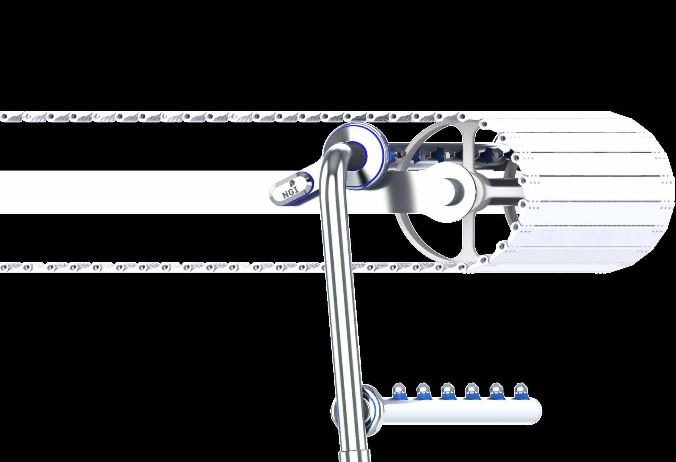
The bearing houses are certfed and designed to comply with EHEDG, 3-A and USDA rules and guidelines and are specifcally designed to minimize risks of contamination and enhance food safety.
The bearing house has a patented waterproof encasement that seals the bearing blocking out dirt and bacteria as well as extending the lifetime of the bearing. The bearings are lubricated for life eliminating the risk of spreading contaminated grease during highpressure cleaning.
The shaft insertion in to the bearing house has a new groundbreaking patented design that enables a waterproof seal to the shaft despite an installation angle of up to 3 degrees misalignment.
Easy installation on diferently designed conveyors
Enhanced food safety
A complete hygienic design minimizing risks of cross-contamination
Reduce energy consumption
Reduce usage of water and cleaning detergents
Go to www.ngi-global.com/bearinghouses to read more and see our product range.
We provide the optimal solution for your application
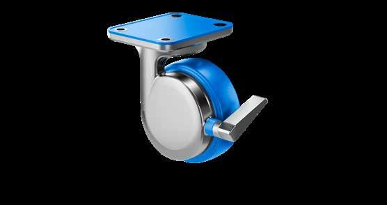
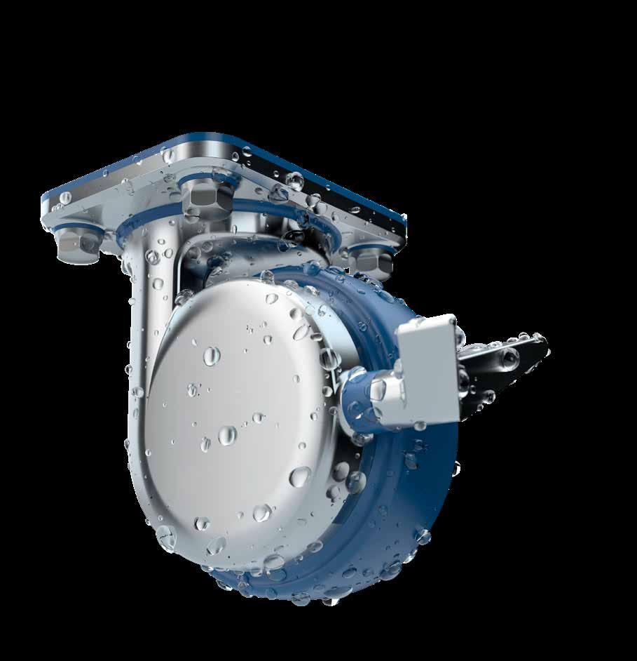
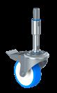
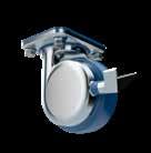
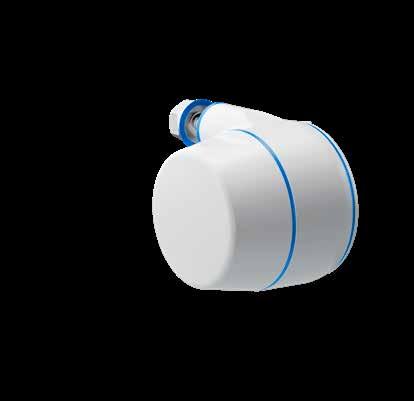
The new certifed hygienic swivel castors from NGI are the only patented castors in the world hygienically designed in accordance to EHEDG, 3-A and USDA design principles securing optimal conditions for cleaning with easy access from all angles.
The hygienic castor from NGI enhances hygienic safety signifcantly as it is designed with a one-sided fork housing providing easy access for cleaning. All surfaces are smooth and drainable as they are either round or have a 3o angle, thus, dirt and bacteria will not accumulate.
The brake is integrated in the fork housing and locking of rotation and pivoting occurs inside the castor. Furthermore, the design of the castor allows quick and easy installation.
Enhanced food safety
A complete hygienic design minimizing risks of cross-contamination
Plug&Play installation
Minimize water usage and use of cleaning detergents


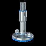
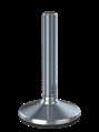


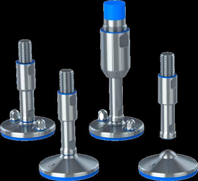
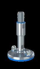
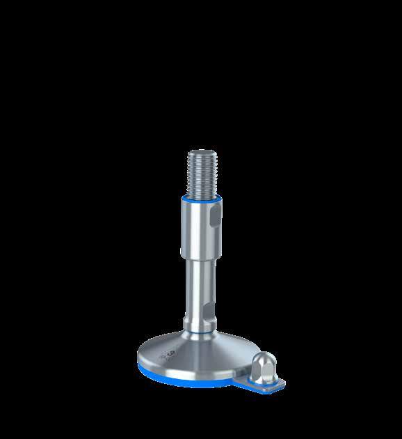
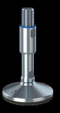
THE only levelling feet in the world hygienically certified by 3-A, USDA & EHEDG standards for use in sanitary production environments
Self-draining surfaces, sealed movable parts and no exposed thread secures absolute minimum cleaning and maximum sanitary safety
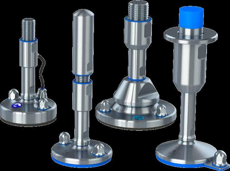
All process industries are subject to increasing regulatory requirements, which increases the focus on ressource consumption, product safety and official hygienic certifcations.
The 3-A, USDA and EHEDG certifed levelling feet reduce the water consumption and cleaning resources in addition to minimizing the risk of contamination in the production.
Choosing NGI’s certifed levelling feet will hygienically enhance your machinery and your customer’s Return-On-Investment (ROI).
All certifed hygienic levelling feet with fastening to floor are delivered with certifed hygienic nuts.
Special Features
- Height variation 107 mm –199 mm
- Weight load up to 110.000 N due to solid footplate & vulcanized rubber
- 3-A logo & EHEDG logo on footplate for certifed recognition
- Thread covered with hygienic sleeve functioning as counter nut
- Optional hygienic top cover
- Safety against exposed thread
- Optimized design for cleaning
- Surface below 0,8 µm RA
- 2 X fxing to the floor
- Extra hygienic sealings
- Delivered with hygienic nuts
Special Features
- Height variation 107 mm – 199 mm
- Weight load up to 110.000 N due to solid footplate & vulcanized rubber
- 3-A logo & EHEDG logo on footplate for certifed recognition
- Thread covered with hygienic sleeve functioning as counter nut
- Optional hygienic top cover
- Optimized design for cleaning
- Surface below 0,8 µm RA
- 2 X fxing to the floor
- Extra hygienic sealings
- Delivered with hygienic nuts
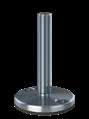
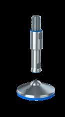
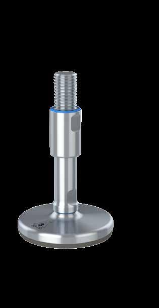
Special features
- Height variation 96 mm – 327 mm
- Weight load up to 95.500 N due to solid footplate & vulcanized rubber
- 3-A and EHEDG logo on footplate for certifed recognition
- 3-A, EHEDG & USDA certifed
- Sealed low-friction thread (lubricated for life)
- Flexible mounting with optional flanges or thread adaptor
- Optimized design for cleaning
- Surface below 0,8 µm RA
- 2 X fxing to the floor
- Extra hygienic sealings
- Delivered with hygienic nuts
• EHEDG certifcation “TYPE EL – 1st CLASS” and 3-A certifcation “88-00”
• USDA certifcation “Dairy” and “NSF/ANIS/3-A 14159-1-2014”
• Self-draining surfaces and safety against exposed thread secures absolute minimum cleaning
• Low-friction washer between spindle and footplate ensures easy adjustment
• All movable parts are 100% hygienically sealed even if the load on the foot is removed


• Vulcanized FDA-approved, anti-vibration, anti-slip rubber blocks out bacteria underneath the footplate
• Stainless steel AISI 304/A2, 1.4301. Optional AISI 316/A4, 1.4401
• More than 1.000 diferent variations available (weight load, height-adjustment, flexible mounting parts)
• All sealings are blue and therefore detectable by scanning systems
• Design and patent protected
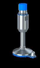
Special Features
- Height variation 104 mm – 206 mm
- Weight load up to 65.000 N
- 3-A logo on footplate for certifed recognition
- Thread covered with hygienic sleeve functioning as counter nut
- Optional top cover
- Optional fxing to the floor including hygienic nuts
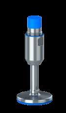
Special Features
- Height variation 101 mm – 197 mm
- Weight load up to 110.000 N due to solid footplate & vulcanized rubber
- 3-A logo on footplate for certifed recognition
- Thread covered with hygienic sleeve functioning as counter nut
- Optional top cover
- Optional fxing to the floor including hygienic nuts
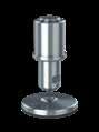
Special Features
- Height variation 109 mm – 208 mm
- Weight load up to 75.000 N
- The footplate and spindle are two separate parts
- Diametrically centered elevation on the footplate
- 3-A logo on footplate for certifed recognition
- Thread covered with hygienic sleeve functioning as counter nut
- Optional top cover
All process industries are subject to increasing regulatory requirements, which increases the focus on ressource consumption, product safety and official hygienic certifcations.
The 3-A, USDA and EHEDG certifed levelling feet reduce the water consumption and cleaning resources in addition to minimizing the risk of contamination in the production.
Choosing NGI’s certifed levelling feet will hygienically enhance your machinery and your customer’s Return-On-Investment (ROI).
All certifed hygienic levelling feet with fastening to floor are delivered with certifed hygienic nuts.

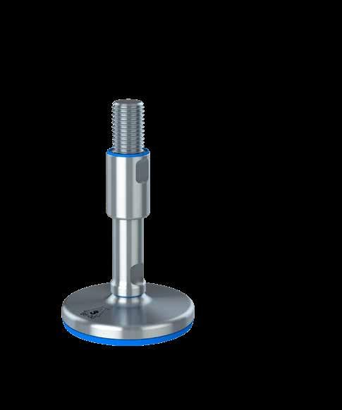
Special Features
- Height variation 99 mm – 335 mm
- Weight load up to 65.000 N
- 3-A logo on footplate for certifed recognition
- Sealed low-friction thread (lubricated for life)
- Flexible mounting with optional flanges or thread adaptor
- No risk of over-adjusting the sleeve and thereby exposing thread
- Optional fxing to the floor including hygienic nuts
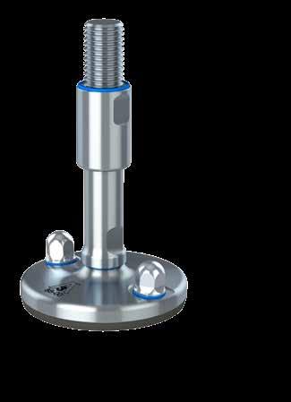
Special Features
- Height variation 96 mm – 326 mm
- Weight load up to 110.000 N due to solid footplate & vulcanized rubber
- 3-A logo on footplate for certifed recognition
- USDA certifed
- Sealed low-friction thread (lubricated for life)
- Flexible mounting with optional flanges or thread adaptor
- Optional fxing to the floor including hygienic nuts
Special Features
- Height variation 115 mm – 218 mm
- Weight load up to 5 ton
- Spindle sizes M16, M20, M24, M30 & M36
- Footplate sizes Ø 80, Ø105, Ø125 & Ø150 mm
- Admits up to 5° slope on floors and equipment
- Vulcanized FDA-approved, anti-vibration, anti-slip rubber
- Thread covered with hygienic sleeve functioning as counter nut

Special Features
- Height variation 104 mm – 335 mm
- Weight load up to 75.000 N
- The footplate and spindle are two separate parts
- Diametrically centered elevation on the footplate
- 3-A logo on footplate for certifed recognition
- 3-A & USDA certifed
- Sealed low-friction thread (lubricated for life)
- Flexible mounting with optional flanges or thread adaptor
Special Features
- Height variation 115 mm – 217 mm
- Weight load up to 5 ton
- Spindle sizes M16, M20, M24, M30 & M36
- Footplate sizes Ø105, Ø125 & Ø150 mm
- Admits up to 10° slope on floors and equipment
- Thread covered with hygienic sleeve functioning as counter nut
Special Features
- Height variation 115 mm – 218 mm
- Weight load up to 5 ton
- Spindle sizes M16, M20, M24, M30 & M36
- Footplate sizes Ø105, Ø125 & Ø150 mm
- Admits up to 5° slope on floors and equipment
- Vulcanized FDA-approved, anti-vibration, anti-slip rubber
- Thread covered with hygienic sleeve functioning as counter nut
- Separated spindle from weighing footplate makes maintenance easier
- Spindle indirectly connected to the load cell through the footplate
All process industries are subject to increasing regulatory requirements, which increases the focus on ressource consumption, product safety and official hygienic certifcations.
The 3-A, USDA and EHEDG certifed levelling feet reduce the water consumption and cleaning resources in addition to minimizing the risk of contamination in the production.
Choosing NGI’s certifed levelling feet will hygienically enhance your machinery and your customer’s Return-On-Investment (ROI). All certifed hygienic levelling feet with fastening to floor are delivered with certifed hygienic nuts.
Special Features
- Height variation 115 mm – 217 mm
- Weight load up to 5 ton
- Spindle sizes M16, M20, M24, M30, M36
- Footplate sizes Ø105, Ø125 & Ø150 mm
- Admits up to 10° slope on floors and equipment
- Separated spindle from weighing footplate makes maintenance easier
- Spindle indirectly connected to the load cell through the footplate.
Special Features
- Height adjustment 155 mm - 285 mm
- Certifed according to USDA hygienic standard
- Designed according to the 3-A and EHEDG hygienic standards
- Available in two standard lengths per diameter size
- Comes with a hygienic sleeve
- Circular arrangement of anchors for best seismic performance
- Spindle sizes M30, M36, M42, M48 & M56 mm
Special Features
- Height adjustment 221 mm - 355 mm
- Certifed according to USDA hygienic standard
- Designed according to the 3-A and EHEDG hygienic standards
- Available in two standard lengths per diameter size
- Comes with a hygienic sleeve
- Circular arrangement of anchors for best seismic performance
- Spindle sizes M56, M64, M72, M80 & M90 mm
It is important to follow these instructions in order to ensure the certifed hygienic design and functionality. This documentation is enclosed with the levelling feet and should always be handed over to the enduser.
This cleaning and maintenance manual describes how to clean and maintain the levelling foot once installed.
This installation manual describes how to install the levelling foot onto the machine or equipment for which it is intended to support.

This declaration of conformity lists all the directives and standards that NGI adheres to. This ensures that products from NGI are always in compliance with currently valid requirements.
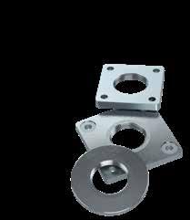
NGI is able to deliver all necessary accessories, which ensures a quick and easy installation of the levelling foot. In addition to supplying standardized accessories we are also able to supply customized accessories.
It is important to follow these instructions in order to ensure the certifed hygienic design and functionality.
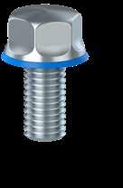
- Certifed in accordance with EHEDG hygienic standard TYPE EL - CLASS AUX
- Minimizes cleaning time and water consumption
- Surfaces with a maximal roughness of 0,8 µm RA
- Available in sizes M6-M24
- Are delivered with all certifed hygienic machine feet with floor fxing
-Certifed in accordance with EHEDG hygienic standard TYPE EL - CLASS AUX
- Minimizes cleaning time and water consumption
- Surfaces with a maximal roughness of 0,8 µm RA
- Available in sizes M5-M24
- Top cover with blue sealing detectable by scanning systems
- Ensures hygienic covering of the exposed top thread
- Minimum cleaning efort due to the self-draining design
- Available in standardized and customized dimensions
- Add-on for the XHFV & ZHFVJ system
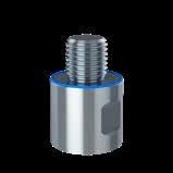
- Adaptor converts the size and type of the thread and extends the sleeve. It has blue sealings detectable by scanning systems.
- Flanges are squared or round and installed by bolting or welding. They are available in a large variety of sizes.
-Certifed in accordance with EHEDG hygienic standard TYPE EL - CLASS AUX
- Minimizes cleaning time and water consumption
- Surfaces with a maximal roughness of 0,8 µm RA
- Available in sizes M5-M24
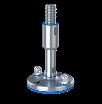
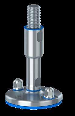
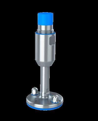
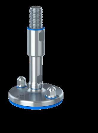
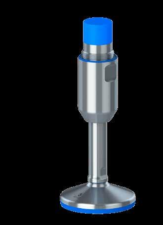
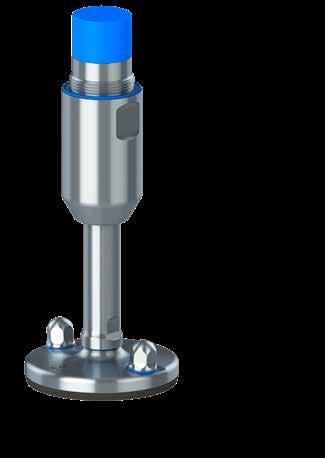
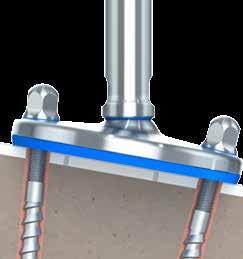
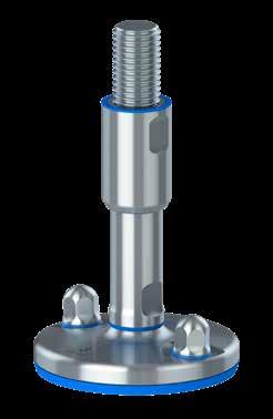
The design and patent protected solid ZHJS levelling foot is the optimal choice for heavy machinery and equipment that has to comply with the strictest hygienic requirements.
The thread is covered with a hygienic sleeve which cannot be overadjusted and secures safety against exposed thread. The sleeve also functions as a counter nut.
The ZHJS is designed to be fastened to the floor by the two fxing holes in the footplate. Hygienic nuts according to EHEDG specifcations are included.
All movable parts are 100% hygienically sealed even if the load on the foot is removed. All sealings are blue and therefore detectable by scanning systems.
Minimum cleaning efort is obtained by the design of the self-draining 0,8 µm RA surfaces. Additionally, the foot is hygienically sealed to the floor by vulcanized FDA-approved, anti-vibration, anti-slip rubber, which blocks out bacteria underneath the footplate.
Available upon request:
- Official 3-A, USDA and EHEDG hygiene certifcates
- Installation instructions
- Cleaning & maintenance instructions
Included in every shipment:
- Certifed hygienic nuts
Certified hygienic
Minimized cleaning time
Minimized water usage

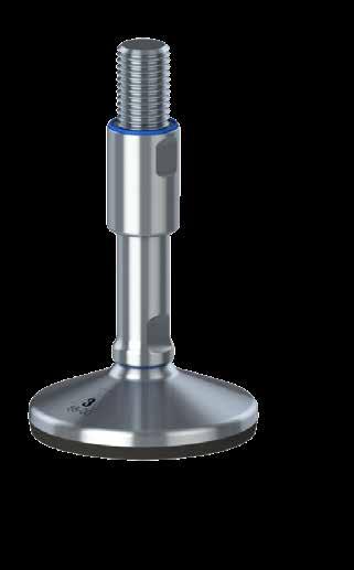
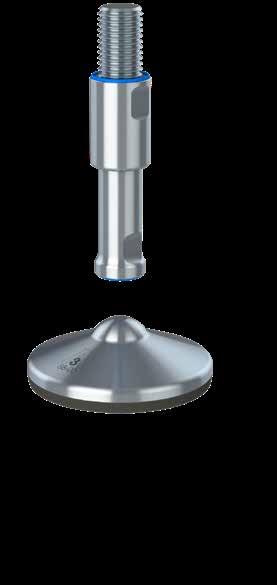
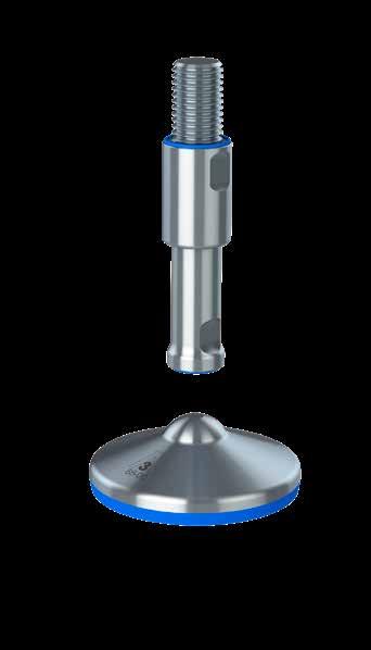
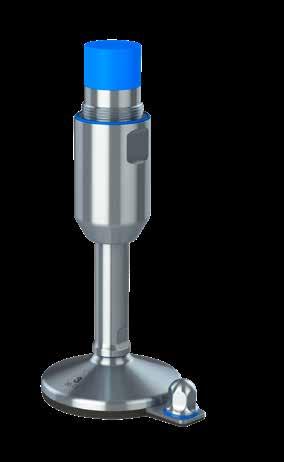
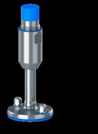
The design and patent protected solid ZHJC levelling foot is the optimal choice for heavy machinery and equipment that has to comply with the strictest hygienic requirements.
The ZHJC is designed to be fastened to the floor by the two fxing holes in the footplate. Hygienic nuts according to EHEDG specifcations are included.
All movable parts are 100% hygienically sealed even if the load on the foot is removed. All sealings are blue and therefore detectable by scanning systems.
Minimum cleaning efort is obtained by the design of the self-draining 0,8 µm RA surfaces. Additionally, the foot is hygienically sealed to the floor by vulcanized FDA-approved, anti-vibration, anti-slip rubber, which blocks out bacteria underneath the footplate.
Available upon request:
- Official 3-A and EHEDG hygiene certifcates
- Installation instructions
- Cleaning & maintenance instructions
Included in every shipment:
- Certifed hygienic nuts
Certified hygienic
Minimized cleaning time
Minimized water usage


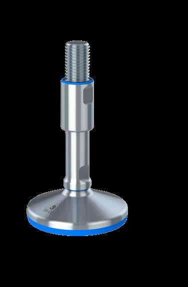
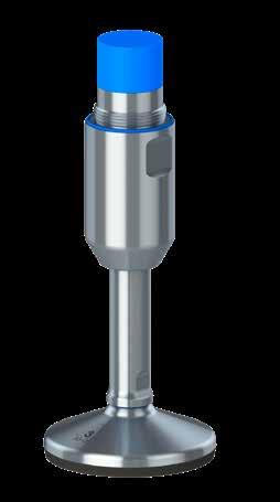
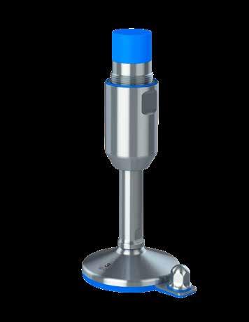
The design and patent protected ZHFVJ is the optimal choice for machinery and equipment that has to comply with the strictest hygieneic requirements.
The ZHFVJ ofers supreme height adjustment 100 mm as standard and has a sealed low-friction thread (lubricated for life).
Flexible mounting with optional flanges or thread adaptor, no risk of overadjusting the sleeve and thereby exposing the thread.
All movable parts are 100% hygienically sealed even if the load on the foot is removed. All sealings are blue and therefore detectable by scanning systems.
Minimum cleaning efort is obtained by the design of the self-draining 0,8 µm RA surfaces. Additionally, the foot is hygienically sealed to the floor by vulcanized FDA-approved, anti-vibration, anti-slip rubber, which blocks out bacteria underneath the footplate.
ZHFVJ is designed to be fastened to the floor by the two fxing holes in the footplate. Hygienic nuts according to EHEDG specifcations are included.
Available upon request:
- Official 3-A, USDA and EHEDG hygiene certifcates
- Installation instructions
- Cleaning & maintenance instructions
Included in every shipment:
- Certifed hygienic nuts
Certified hygienic
Minimized cleaning time
Minimized water usage
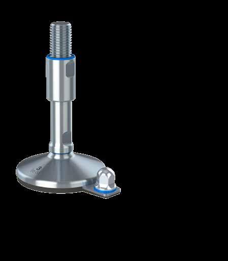
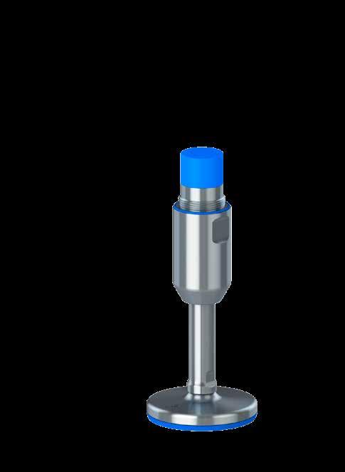
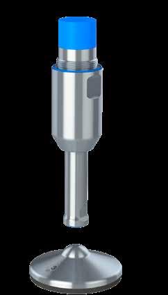
The design and patent protected XH levelling foot is the optimal choice for machinery and equipment that has to comply with the strictest hygienic requirements.
All movable parts are 100% hygienically sealed even if the load on the foot is removed. All sealings are blue and therefore detectable by scanning systems.
Minimum cleaning efort is obtained by the design of the selfdraining surfaces. Additionally, the foot is hygienically sealed to the floor by vulcanized FDA-approved, anti-vibration, anti-slip rubber, which blocks out bacteria underneath the footplate.
Available upon request:
- Official 3-A hygiene certifcate
- Installation instructions
- Cleaning & maintenance instructions
Minimized
Minimized
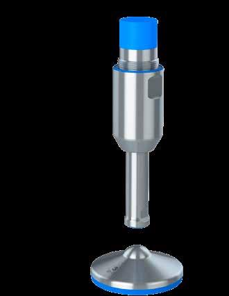
The design and patent protected XH Fixing levelling foot is the optimal choice for machinery and equipment that has to comply with the strictest hygienic requirements.
The XH Fixing is designed to be fastened to the floor by the fxing plate. Certifed hygienic levelling feet are always delivered with hygienic nuts.
All movable parts are 100% hygienically sealed even if the load on the foot is removed. All sealings are blue and therefore detectable by scanning systems.
Minimum cleaning efort is obtained by the design of the self-draining surfaces. Additionally, the foot is hygienically sealed to the floor by vulcanized FDA-approved, anti-vibration, anti-slip rubber, which blocks out bacteria underneath the footplate.
Available upon request:
- Official 3-A hygiene certifcate
- Installation instructions
- Cleaning & maintenance instructions
Included in every shipment:
- Certifed hygienic nuts
Minimized cleaning time Certified hygienic
Minimized water usage
The design and patent protected solid XHG levelling foot is the optimal choice for heavy machinery and equipment that has to comply with the strictest hygienic requirements.
All movable parts are 100% hygienically sealed even if the load on the foot is removed. All sealings are blue and therefore detectable by scanning systems.
Minimum cleaning efort is obtained by the design of the selfdraining surfaces. Additionally, the foot is hygienically sealed to the floor by vulcanized FDA-approved, anti-vibration, anti-slip rubber, which blocks out bacteria underneath the footplate.
Available upon request:
- Official 3-A hygiene certifcate
- Installation instructions
- Cleaning & maintenance instructions
Certified hygienic
Minimized cleaning time
Minimized water usage
The design and patent protected solid XHJ levelling foot is the optimal choice for heavy machinery and equipment that has to comply with the strictest hygienic requirements.
The XHJ is designed to be fastened to the floor by the two fxing holes in the footplate. Certifed hygienic levelling feet are always delivered with hygienic nuts.
All movable parts are 100% hygienically sealed even if the load on the foot is removed. All sealings are blue and therefore detectable by scanning systems.
Minimum cleaning efort is obtained by the design of the self-draining surfaces. Additionally, the foot is hygienically sealed to the floor by vulcanized FDA-approved, antivibration, anti-slip rubber, which blocks out bacteria underneath the footplate.
Available upon request:
- Official 3-A hygiene certifcate
- Installation instructions
- Cleaning & maintenance instructions
Included in every shipment:
- Certifed hygienic nuts
Minimized cleaning time Certified hygienic
Minimized water usage
The design and patent protected XHT levelling foot is the optimal choice for machinery and equipment that has to comply with the strictest hygienic requirements.
The XHT consists of a separated footplate and spindle connected by the diametrically centered elevation on the footplate.
All movable parts are 100% hygienically sealed. All sealings are blue and therefore detectable by scanning systems.
Minimum cleaning efort is obtained by the design of the selfdraining surfaces. Additionally, the foot is hygienically sealed to the floor by vulcanized FDA-approved, anti-vibration, anti-slip rubber, which blocks out bacteria underneath the footplate.
Available upon request:
- Official 3-A hygiene certifcate
- Installation instructions
- Cleaning & maintenance instructions
Minimized cleaning time Certified hygienic
Minimized water usage
The design and patent protected XHFV levelling foot is the optimal choice for machinery and equipment that has to comply with the strictest hygienic requirements.
The XHFV ofers supreme height adjustment 100 mm as standard and has a sealed low-friction thread (lubricated for life).
Flexible mounting with optional flanges or thread adaptor.
All movable parts are 100% hygienically sealed even if the load on the foot is removed. All sealings are blue and therefore detectable by scanning systems.
Minimum cleaning efort is obtained by the design of the self-draining surfaces. Additionally, the foot is hygienically sealed to the floor by vulcanized FDA-approved, antivibration, anti-slip rubber, which blocks out bacteria underneath the footplate.
Available upon request:
- Official 3-A & USDA hygiene certifcates
- Installation instructions
- Cleaning & maintenance instructions
Certified hygienic
Minimized cleaning time
Minimized water usage
The design and patent protected XHFV Fixing levelling foot is the optimal choice for machinery and equipment that has to comply with the strictest hygienic requirements.
The XHFV Fixing is designed to be fastened to the floor by the fxing plate. Certifed hygienic levelling feet are always delivered with hygienic nuts.
The XHFV Fixing ofers supreme height adjustment 100 mm as standard and has a sealed low-friction thread (lubricated for life).
Flexible mounting with optional flanges or thread adaptor.
All movable parts are 100% hygienically sealed even if the load on the foot is removed. All sealings are blue and therefore detectable by scanning systems.
Minimum cleaning efort is obtained by the design of the selfdraining surfaces. Additionally, the foot is hygienically sealed to the floor by vulcanized FDA-approved, anti-vibration, anti-slip rubber, which blocks out bacteria underneath the footplate.
Available upon request:
- Official 3-A & USDA hygiene certifcates
- Installation instructions
- Cleaning & maintenance instructions
Included in every shipment:
- Certifed hygienic nuts
Minimized cleaning time Certified hygienic
Minimized water usage
The design and patent protected solid XHFVG levelling foot is the optimal choice for heavy machinery and equipment that has to comply with the strictest hygienic requirements.
The XHFVG ofers supreme height adjustment 100 mm as standard and has a sealed low-friction thread (lubricated for life).
Flexible mounting with optional flanges or thread adaptor, no risk of over-adjusting the sleeve and thereby exposing the thread.
All movable parts are 100% hygienically sealed even if the load on the foot is removed. All sealings are blue and therefore detectable by scanning systems.
Minimum cleaning efort is obtained by the design of the self-draining surfaces. Additionally, the foot is hygienically sealed to the floor by vulcanized FDA-approved, antivibration, anti-slip rubber, which blocks out bacteria underneath the footplate.
Certified hygienic
Minimized cleaning time
Minimized water usage
Available upon request:
- Official 3-A & USDA hygiene certifcates
- Installation instructions
- Cleaning & maintenance instructions
The design and patent protected solid XHFVJ levelling foot is the optimal choice for heavy machinery and equipment that has to comply with the strictest hygienic requirements.
The XHFVJ ofers supreme height adjustability up to 100 mm as standard and has a sealed low-friction thread (lubricated for life).
The XHFVJ is designed to be fastened to the floor by the two fxing holes in the footplate. Certifed hygienic levelling feet are always delivered with hygienic nuts.
Flexible mounting with optional flanges or thread adaptor.
All movable parts are 100% hygienically sealed even if the load on the foot is removed. All sealings are blue and therefore detectable by scanning systems.
Minimum cleaning efort is obtained by the design of the selfdraining surfaces. Additionally, the foot is hygienically sealed to the floor by vulcanized FDA-approved, anti-vibration, antislip rubber, which blocks out bacteria underneath the footplate.
Available upon request:
- Official 3-A & USDA hygiene certifcates
- Installation instructions
- Cleaning & maintenance instructions
Included in every shipment:
- Certifed hygienic nuts
Certified hygienic
Minimized cleaning time
Minimized water usage
The design and patent protected XHFVT levelling foot is the optimal choice for machinery and equipment that has to comply with the strictest hygienic requirements.
The XHFVT consists of a separated footplate and spindle connected by the diametrically centered elevation on the footplate.
The XHFVT ofers supreme height adjustment 100 mm as standard and has a sealed low-friction thread (lubricated for life).
Flexible mounting with optional flanges or thread adaptor.
All movable parts are 100% hygienically sealed. All sealings are blue and therefore detectable by scanning systems.
Minimum cleaning efort is obtained by the design of the self-draining surfaces. Additionally, the foot is hygienically sealed to the floor by vulcanized FDA-approved, antivibration, anti-slip rubber, which blocks out bacteria underneath the footplate.
Available upon request:
- Official 3-A & USDA hygiene certifcates
- Installation instructions
- Cleaning & maintenance instructions
Certified hygienic
Minimized cleaning time
Minimized water usage
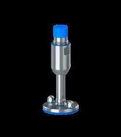
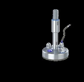
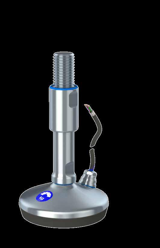
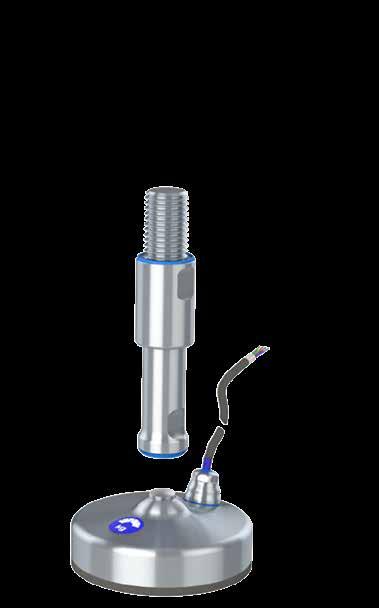
The design and patent protected XHW weighing levelling foot is the optimal choice for supporting and weighing machinery, equipment, tanks and vessels in environments with strict hygienic requirements. The load cell is secured, guided and protected inside the foot.
- Secured: Load cell is secured against hazardous mechanical external impacts
- Guided: Can obtain strong forces in all directions without afecting the load cell
- Protected: Against external influences like corrosion, temperatures and bacteria
The XHW levelling foot is hygienically sealed to the floor by vulcanized FDA-approved, anti-vibration, anti-slip rubber, which blocks out bacteria underneath the footplate and protects the load cell.
- Maintenance free and height-adjustable compact design
- Simple and fast installation - no mounting kit needed
- The diferent load cells cover a span of 30kg to 5000 kg
Minimized cleaning time Certified hygienic
Minimized water usage

- Designed according to the 3-A and EHEDG hygienic standards
- Stainless steel AISI 304/A2, 1.4301. Optional AISI 316/A4, 1.4401
Available upon request:
- Datasheet
- Installation instructions
- Cleaning & maintenance instructions
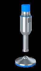
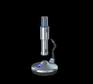
The design and patent protected XHGW weighing levelling foot is the optimal choice for supporting and weighing machinery, equipment, tanks and vessels in environments with strict hygienic requirements. The load cell is secured, guided and protected inside the foot.
- Secured: Load cell is secured against hazardous mechanical external impacts
- Guided: Can obtain strong forces in all directions without afecting the load cell
- Protected: Against external influences like corrosion, temperatures and bacteria
- Maintenance free and height-adjustable compact design
- Simple and fast installation - no mounting kit needed
- The diferent load cells cover a span of 30 kg to 5.000 kg
- Designed according to the 3-A and EHEDG hygienic standards
- Stainless steel AISI 304/A2, 1.4301. Optional AISI 316/A4, 1.4401
Available upon request:
- Datasheet
- Installation instructions
- Cleaning & maintenance instructions
Certified hygienic
Minimized cleaning time
Minimized water usage
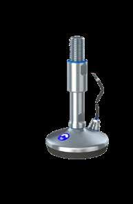
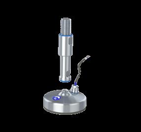
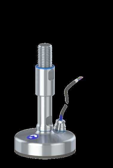
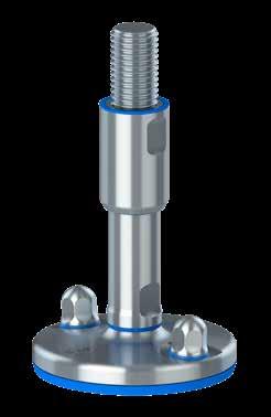
The design and patent protected XHJW weighing levelling foot is the optimal choice for supporting and weighing machinery, equipment, tanks and vessels in environments with strict hygienic requirements. The load cell is secured, guided and protected inside the foot.
- Secured: Load cell is secured against hazardous mechanical external impacts
- Guided: Can obtain strong forces in all directions without afecting the load cell
- Protected: Against external influences like corrosion, temperatures and bacteria
The XHJW is designed to be fastened to the floor by the two fxing holes in the footplate.
- Maintenance free and height-adjustable compact design
- Simple and fast installation - no mounting kit needed
- The diferent load cells cover a span of 30 kg to 5.000 kg
- Designed according to the 3-A and EHEDG hygienic standards
- Stainless steel AISI 304/A2, 1.4301. Optional AISI 316/A4, 1.4401
Available upon request:
- Datasheet
- Installation instructions
- Cleaning & maintenance instructions
Certified hygienic
Minimized cleaning time
Minimized water usage
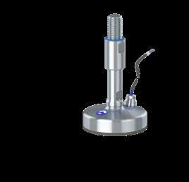
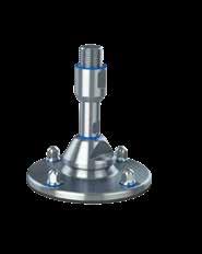
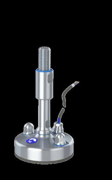
The design and patent protected XHTW weighing levelling foot is the optimal choice for supporting and weighing machinery, equipment, tanks and vessels in environments with strict hygienic requirements. The load cell is secured, guided and protected inside the foot.
- Secured: Load cell is secured against hazardous mechanical external impacts
- Guided: Can obtain strong forces in all directions without afecting the load cell
- Protected: Against external influences like corrosion, temperatures and bacteria
The XHTW consists of a separated footplate and spindle connected by the diametrically centered elevation on the weighing footplate. Additionally, the levelling foot is hygienically sealed to the floor by vulcanized FDA-approved, anti-vibration, anti-slip rubber, which blocks out bacteria underneath the footplate and protects the load cell.
- Maintenance free and height-adjustable compact design
- Simple and fast installation - no mounting kit needed
- The diferent load cells cover a span of 30 kg to 5000 kg
- Designed according to the 3-A and EHEDG hygienic standards
- Stainless steel AISI 304/A2, 1.4301. Optional AISI 316/A4, 1.4401
Available upon request:
- Datasheet
- Installation instructions
- Cleaning & maintenance instructions
Certified hygienic
Minimized cleaning time
Minimized water usage
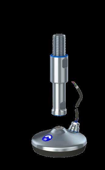
The design and patent protected XHGTW weighing levelling foot is the optimal choice for supporting and weighing machinery, equipment, tanks and vessels in environments with strict hygienic requirements. The load cell is secured, guided and protected inside the foot.
- Secured: Load cell is secured against hazardous mechanical external impacts
- Guided: Can obtain strong forces in all directions without afecting the load cell
- Protected: Against external influences like corrosion, temperatures and bacteria
The XHGTW consists of a separated footplate and spindle connected by the diametrically centered elevation on the weighing footplate.
- Maintenance free and height-adjustable compact design
- Simple and fast installation - no mounting kit needed
- The diferent load cells cover a span of 30 kg to 5.000 kg
Minimized cleaning time Certified hygienic
Minimized water usage
- Designed according to the 3-A and EHEDG hygienic standards
- Stainless steel AISI 304/A2, 1.4301. Optional AISI 316/A4, 1.4401
Available upon request:
- Datasheet
- Installation instructions
- Cleaning & maintenance instructions
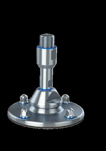
The design and patent protected seismic XHJSE (S) levelling foot is the optimal choice for machinery, equipment, tanks and vessels located in areas subject to earthquakes and also has to to comply with the strictest hygienic requirements.
- Total seismic stability and bolted fastening to concrete floors
- Movable set-up - no concrete moulding required
- Seismic anchors chosen and approved by our experienced partner Hilti
- Patented locking mechanism secures seismic stability
- Calculated according to international seismic standard NZS 4219
- Design verifed through Finite element simulation
- Designed according to the 3-A and EHEDG hygienic standards
- Certifed according to USDA hygienic standard
- Stainless steel AISI 304/A2, 1.4301. Optional AISI 316/A4, 1.4401
Available upon request:
- Official USDA hygienic certifcate
- Datasheet calculations
- Installation instructions
- Cleaning & maintenance instructions
Minimized cleaning time Certified hygienic
Minimized water usage


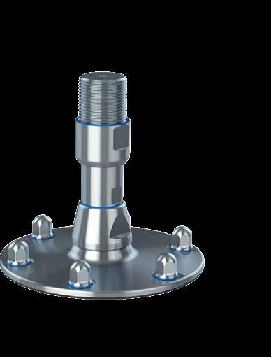
The design and patent protected seismic XHJSE (L) levelling foot is the optimal choice for machinery, equipment, tanks and vessels located in areas subject to earthquakes and also has to to comply with the strictest hygienic requirements.
- Total seismic stability and bolted fastening to concrete floors
- Movable set-up - no concrete moulding required
- Seismic anchors chosen and approved by our experienced partner Hilti
- Patented locking mechanism secures seismic stability
- Calculated according to international seismic standard NZS 4219
- Design verifed through Finite element simulation
- Designed according to the 3-A and EHEDG hygienic standards
- Certifed according to USDA hygienic standard
- Stainless steel AISI 304/A2, 1.4301. Optional AISI 316/A4, 1.4401
Available upon request:
- Official USDA hygienic certifcate
- Datasheet calculations
- Installation instructions
- Cleaning & maintenance instructions
Minimized cleaning time Certified hygienic
Minimized water usage
1. Rinse with water (maximum temperature ~40°C on proteins).
2. Distribute and cover all surfaces with foaming alkaline detergent for minimum 10 minutes. All standard products within the industry can be used. Follow supplier recommendations for temperature (maximum 100°C) and concentration depending on foaming detergent.
3. Rinse with hot water (maximum 100°C) with lowmedium pressure (approximately 8-12 bar) until it is visibly clean. Cleaning of the levelling foot including sealings and dome-headed nuts can normally be done with a spraying nozzle pointing in a downwards direction approximately 45°. For heavy duty cleaning a more direct-oriented nozzle can be necessary. Be careful not to damage the sealings if high pressure cleaning is used. Keep nozzle at minimum 200-300 mm distance.
4. Mechanical cleaning may be necessary if the levelling foot is severely soiled. Cleaning must be executed with a soft brush or soft plastic scraper together with a more direct pointing nozzle spray. Steel scraper, steel brush or other sharp metallic tools are strictly prohibited, since the sealings can be severely damaged and the steel surfaces will be scratched.
1. If the sealings on the sleeve are damaged they must be replaced. Always use genuine spare parts from NGI.
2. If the sealing between the foot and the spindle is damaged, replace the whole levelling foot and install a new one. An assembled levelling foot cannot be separated.
3. Load on the levelling foot must be obtained in order for the footplate to be hygienically sealed to the floor.
4. For a levelling foot for floor fxing always make sure that the floor fxing nut or bolt is tightened as specifed in the installation manual. Tighten if necessary. If replacement of nuts or washers is always use genuine spare parts from NGI.
5. If any readjustments are necessary the levelling foot and the nearest surroundings must be cleaned carefully to prevent any soil from entering the sleeve.
It is important to follow these instructions in order to ensure the certifed hygienic design and functionality.
This documentation is enclosed with the levelling feet and should always be handed over to the end-user.
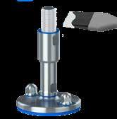
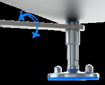
0A. Prior to installation of the levelling foot ensure that the floor does not exceed maximum slope.
0B. When installing, make sure that the footplate does not span over cracks, grout lines or other floor imperfections. If unavoidable, seal the cavity with bonding material under and around the edge of the footplate.
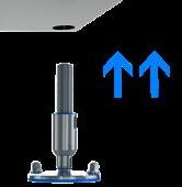
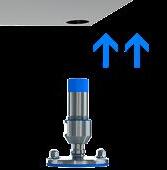
1A. Lift or jack up the machinery or equipment to install the levelling foot.
1B. Make sure that the sealing is correctly fxed on top of the sleeve. Grease the exposed thread with FoodLube Universal Grease and make sure to remove any excess grease after installation.
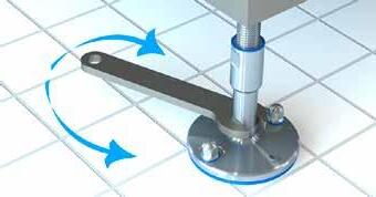
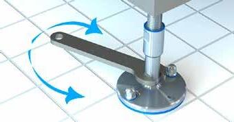
2. Install the levelling foot and use a wrench to adjust the vertical position and make sure that the engagement is no less than the diameter of the thread.
Repeat step 0A-2 for all feet supporting the machinery.
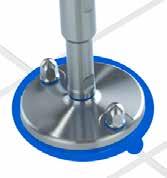
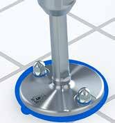
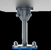
Lower the machinery so that the feet rest on the floor. Perform fnal height and levelling adjustments if needed and ensure that the load is uniformly distributed on all feet.
3. Use a wrench to rotate and tighten the sleeve against the machinery or equipment. Make sure that the sleeve is tightened to counter-lock the levelling foot and cover the thread.
If the levelling foot is not fully inserted into the machinery or equipment the thread will become partly exposed. In this case, it is not correctly installed and will neither meet 3A, USDA & EHEDG hygienic demands nor load specifications.
It is important to follow these instructions in order to ensure the certifed hygienic design and functionality.
This documentation is enclosed with the levelling feet and should always be handed over to the end-user.
0A. Prior to installation of the levelling foot ensure that the floor does not exceed maximum slant.
0B. When installing, make sure that the footplate does not span over cracks, grout lines or other floor imperfections. If unavoidable, seal the cavity with bonding material under and around the edge of the footplate.
1A. Lift or jack up the machinery or equipment to install the levelling foot.
1B. Apply the optional flange to the machinery by welding or bolting. For a hygienic solution use dome-headed nuts.
2. Make sure that the sealing is correctly fxed on top of the sleeve and install the levelling foot using a wrench and apply Loctite if necessary.
Repeat step 0A-2 for all feet supporting the machinery.
Lower the machinery so that the feet rest on the floor. Perform fnal height and levelling adjustments if needed and ensure that the load is uniformly distributed on all feet.
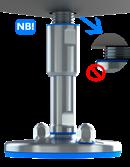
No maintenance lubrication is needed. The sealed low-friction thread is lubricated for life and the levelling foot is secured against over-adjustment and exposure of the thread.
It is important to follow these instructions in order to ensure the certifed hygienic design and functionality.
This documentation is enclosed with the levelling feet and should always be handed over to the end-user.
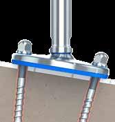
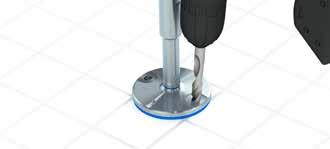
1. Hold the drill in a 3° angle so that it fts the direction of the fxing hole in the levelling foot. Drill the hole through the footplate down into the floor.
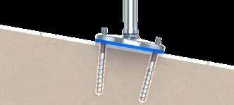
2. When an achoring rod is used, make sure to allow the mortar to dry according to the manufacturer’s instructions. When an expanding anchor is used, make sure to also follow the manufacturer’s instructions.
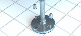
3. Add the prescribed certifed hygienic nuts using a maximum torque of 10-12 Nm.


88-01


NGI fundamentally adheres to all applicable directives and standards. All information is based on the current state of knowledge and is subject to change. We attentively follow the revisions and amendments to these directives and will design our products accordingly. This ensures that products from NGI are always in compliance with currently valid requirements.
Our product category is not covered by the scope of application of the EC directive for machinery. For this reason, they cannot be furnished with the CE marking in accordance with the EC directive for machinery.
NGI A/S, Virkelyst 3-7, 9400 Nørresundby, Denmark, hereby declares that the design is according to 3-A, USDA & EHEDG guidelines and regulations specifed in the following.
Furthermore, we declare that the listed materials applied in our products comply with the demands for materials used within the food and pharmaceutical industries.
Materials, Surface Roughness, Fabrication and Geometry
Metallic surfaces are constructed from AISI 304 grade stainless steel and are corrosion resistant under the specifed conditions of use including those of cleaning. The elastomeric components are constructed from FDA approved NBR and TPE Santoprene® rubber material. The sealing washers are constructed from Aramid fber material. All materials used are considered non-toxic and are nonabsorbent.
All exposed metallic surfaces are fnished to maximum surface roughness values of 0.8 µm Ra. All elastomeric components and sealing washers are left as moulded with no hand trimming and all surfaces are considered smooth enough to ensure superior cleanability.
There are no exposed dissimilar metal-to-metal contact areas in the construction where galvanic corrosion could occur.
Hygienic seals permit access for easy cleaning with no inaccessible pockets or crevices.
There is no risk of exposed threads and no unsealed metal-to-metal joints in the fnished construction.
All exposed surfaces have a smooth fnish so that soil may be cleaned from the surface using manual cleaning techniques and be free of pits, folds, cracks, crevices, and other imperfections in the fnal fabricated form.
Drainability and Installation
The levelling feet are designed to be self-draining and contain no horizontal ledges. Comprehensive instructions are provided containing detailed information to ensure compliance with the 3-A, USDA & EHEDG design criteria.
The 3-A Sanitary Standard 88-00 requires that when leveling feet are properly mounted on the equipment, they shall provide a minimum clearance between the lowest part of the equipment and the floor of no less than 4.0 inches (102 mm) if the equipment outlines an area in which no point is more than 12.5 inches (318 mm) from its’ nearest edge. If the equipment outlines an area in which any point is more than 12.5 inches (318 mm) from its’ nearest edge the clearance shall be at least 6 inches (152 mm).
The EHEDG guideline recommends a minimum clearance between the equipment and the floor or wall of 300 mm for easy cleaning and inspection.
When fasteners are required only dome nuts must be used. The exposed interfaces shall be sealed with sealing washers and there must be no threads exposed in the installed confguration of the levelling feet.
Certified hygienic
Minimized cleaning time
Minimized water usage
Foot bases can be sealed to the floor if required. And the installation instructions make recommendations not to span over floor imperfections or grout lines without the addition of proprietary sealing compounds.
Maximum torque values are specifed as appropriate on fastening arrangements to avoid over-compression of sealing washers and gaskets.
Maintenance instructions are clearly defned and prohibit the use of non-genuine replacement parts.
Cleaning instructions describe typical cleaning procedures with recommended maximum temperatures/pressures and stipulate the use of non-abrasive cleaning aids.
The design does not contain dead spaces and avoid accumulation of soil, microorganism’s insects and other vermin in areas which cannot be easily cleaned.
Sealing and thread locking compounds used in the construction are non-toxic in the cured state.
No lubricants, insulation material or signal transfer liquids are used in the construction.
Standards and directives
EN 1672-2:2005 Food machinery / General design principles/Part 2: Hygiene requirements.
EN ISO 14 159 2004 Safety of machinery – Hygiene requirements for the design of machinery.
Document 13 EHEDG guideline on the hygienic design of apparatus for open processes.
EHEDG Class I AUX: The hygienic design criteria evaluation report concludes that the designs meet the criteria for hygienic equipment class I AUX for components situated in the non-food area and are accessible for easy cleaning without dismantling.
3-A sanitary standard for machine levelling feet and supports.
USDA Guidelines for the sanitary design and fabrication of dairy processing equipment June 2001.
EU regulations
852/2004 on the hygiene of foodstufs.
853/2004 specifc hygiene rules for food of animal origin.
854/2004 specifc rules for the organization of official controls on products of animal origin intended for human consumption.
1935/2004 on materials and articles intended to come into contact with food.
The declaration of materials concerns the following Applications
Application: Steel components, e.g. spindle, sleeve and cover for foot
Material type: Stainless steel, AISI 304/A2 (X5CrNi18-10), Euro norm 1.4301. By request: Stainless steel, AISI 316/A4 (X 5 CrNiMo 17 12 2), Euronorm 1.4401
Compliance: EN 10204 Type 2.2. NGI A/S states that the product is in compliance with the order with indication of results of nonspecifc inspection. NGI A/S has got EN 10204 type 3.1 ins pection certifcates on all material used in the products but not specifed for each foot.
In the directive 94/9/EC, Equipment for potentially explosive atmospheres, also known as the ATEX directive, equipment without its own potential source of ignition are not covered, nor shall be marked according to the directive. However, NGI levelling feet are suitable for use in all ATEX zones.
Application: Foot base for NGI A/S’s hygienic machine feet
Material type: NBR (NNF-75)
Color: Blue
Hardness: 72 ± 3 Shore A DIN 53 505
Range of temperature: Min -35°C to Max +110°C
Compliance:
REACH: In accordance with regulation EC 1907/2006. Do not contain any substances above 0.1% (w/w) from: The Candidate List of Substances of Very High Concern (16.01.2020). Annex XVII (19-11-2019)
RoHS 2 & RoHS 3 In accordance with the directive 2011/65/EC and 2015/863/EC OF EUROPEAN PARLIAMENT AND OF THE COUNCIL.
ADI free: Does not contain any substances originating from humans or animals.
Bisphenols: Does not contain Bisphenols as described in 1895/2005/EEC. Nor BPA, BADGA, BFDGE or NOGE.
ODS: Does not contain ozone depleting substances. In accordance with the Regulation EC 1005/2009 OF EUROPEAN PARLIAMENT AND OF THE COUNCIL OF 16 SEPTEMBER 2009 and Regulation EC 2037/2000 OF EUROPEAN PARLIAMENT AND OF THE COUNCIL OF 29 JUNE 2000.
Conflict
Materials: In accordance with US Law: ”Dodd Frank Wall Street Reform & Consumer Protection Act”, sec. 1502, of 21.07.2010.
GMP: Good manufacturing process in accordance with 2023/2006 EC.
Hazardous
materials: Does not contain any hazardous substances as described in the Hong Kong International Convention for the Safe and Environmental. Sound Recycling of ships, 2009.
Phthalates: Does not contain phthalates.
FDA: Guideline 21 CFR 177.2600
Application: Sealing ring between steel components for NGI’s machine feet.
Material type: Silicon rubber
Hardness: 60 Shore A
Color: RAL 5010 (blue)
Range of temperature: Min -60°C to Max +200°C
Storage: According to ISO 2230
Compliance: FDA: Guideline 21 CFR 177.2600
RoHS 2: In accordance with the Directive 2011/65/EC OF EUROPEAN PARLIAMENT AND OF THE COUNCIL.
GMP: Good manufacturing process in accordance with 2023/2006 EC.
- XH, XHT, XHG, XHJ, XHFV, XHFVT, XHFVG, XHFVJ
NGI fundamentally adheres to all applicable directives and standards. All information is based on the current state of knowledge and is subject to change. We attentively follow the revisions and amendments to these directives and will design our products accordingly. This ensures that products from NGI are always in compliance with currently valid requirements.
Our product category is not covered by the scope of application of the EC directive for machinery. For this reason, they cannot be furnished with the CE marking in accordance with the EC directive for machinery.
NGI A/S, Virkelyst 3-7, 9400 Nørresundby, Denmark, hereby declares that the design is according to 3-A, USDA & EHEDG guidelines and regulations specifed in the following.
Furthermore, we declare that the listed materials applied in our products comply with the demands for materials used within the food and pharmaceutical industries.
- XH, XHT, XHG, XHJ, XHFV, XHFVT, XHFVG, XHFVJ
Metallic surfaces are constructed from AISI 304 grade stainless steel and are corrosion resistant under the specifed conditions of use including those of cleaning. The elastomeric components are constructed from FDA approved NBR and TPE Santoprene® rubber material. The sealing washers are constructed from Aramid fber material. All materials used are considered non-toxic and are non-absorbent.
All exposed metallic surfaces are fnished to maximum surface roughness values of 1.6 pm Ra. All elastomeric components and sealing washers are left as moulded with no hand trimming and all surfaces are considered smooth enough to ensure superior cleanability.
There are no exposed dissimilar metal-to-metal contact areas in the construction where galvanic corrosion could occur.
Hygienic seals permit access for easy cleaning with no inaccessible pockets or crevices.
There is no risk of exposed threads and no unsealed metal-to-metal joints in the fnished construction.
All exposed surfaces have a smooth fnish so that soil may be cleaned from the surface using manual cleaning techniques and be free of pits, folds, cracks, crevices, and other imperfections in the fnal fabricated form.
Drainability and Installation
The levelling feet are designed to be self-draining and contain no horizontal ledges. Comprehensive instructions are provided containing detailed information to ensure compliance with the 3-A, USDA & EHEDG design criteria.
The 3-A Sanitary Standard 88-00 requires that when leveling feet are properly mounted on the equipment, they shall provide a minimum clearance between the lowest part of the equipment and the floor of no less than 4.0 inches (102 mm) if the equipment outlines an area in which no point is more than 12.5 inches (318 mm) from its’ nearest edge. If the equipment outlines an area in which any point is more than 12.5 inches (318 mm) from its’ nearest edge the clearance shall be at least 6 inches (152 mm).
The EHEDG guideline recommends a minimum clearance between the equipment and the floor or wall of 300 mm for easy cleaning and inspection.
When fasteners are required only dome nuts must be used. The exposed interfaces shall be sealed with sealing washers and there must be no threads exposed in the installed confguration of the levelling feet.
- XH, XHT, XHG, XHJ, XHFV, XHFVT, XHFVG, XHFVJ
Foot bases can be sealed to the floor if required. And the installation instructions make recommendations not to span over floor imperfections or grout lines without the addition of proprietary sealing compounds.
Maximum torque values are specifed as appropriate on fastening arrangements to avoid over-compression of sealing washers and gaskets.
Maintenance instructions are clearly defned and prohibit the use of non-genuine replacement parts.
Cleaning instructions describe typical cleaning procedures with recommended maximum temperatures/pressures and stipulate the use of non-abrasive cleaning aids.
The design does not contain dead spaces and avoid accumulation of soil, microorganism’s insects and other vermin in areas which cannot be easily cleaned.
Sealing and thread locking compounds used in the construction are non-toxic in the cured state.
No lubricants, insulation material or signal transfer liquids are used in the construction.
EN 1672-2:2005 Food machinery / General design principles/Part 2: Hygiene requirements.
EN ISO 14 159 2004 Safety of machinery – Hygiene requirements for the design of machinery.
3-A sanitary standard for machine levelling feet and supports.
USDA Guidelines for the sanitary design and fabrication of dairy processing equipment June 2001.
EU regulations
852/2004 on the hygiene of foodstufs.
853/2004 specifc hygiene rules for food of animal origin.
854/2004 specifc rules for the organization of official controls on products of animal origin intended for human consumption.
1935/2004 on materials and articles intended to come into contact with food.
Certified hygienic
Minimized cleaning time
Minimized water usage
- XH, XHT, XHG, XHJ, XHFV, XHFVT, XHFVG, XHFVJ
The declaration of materials concerns the following Applications
Application: Steel components, e.g. spindle, sleeve and cover for foot
Material type: Stainless steel, AISI 304/A2 (X5CrNi18-10), Euro norm 1.4301. By request: Stainless steel, AISI 316/A4 (X 5 CrNiMo 17 12 2), Euronorm 1.4401
Compliance: EN 10204 Type 2.2. NGI A/S states that the product is in compliance with the order with indication of results of nonspecifc inspection.
NGI A/S has got EN 10204 type 3.1 ins pection certifcates on all material used in the products but not specifed for each foot.
In the directive 94/9/EC, Equipment for potentially explosive atmospheres, also known as the ATEX directive, equipment without its own potential source of ignition are not covered, nor shall be marked according to the directive. However, NGI levelling feet are suitable for use in all ATEX zones.
Application: Foot base for NGI A/S’s hygienic machine feet
Material type: NBR (NNF-75)
Color: Black & blue
Hardness: 72 ± 3 Shore A DIN 53 505
Range of temperature: Min -35°C to Max +110°C
Compliance:
REACH: In accordance with regulation EC 1907/2006. Do not contain any substances above 0.1% (w/w) from: The Candidate List of Substances of Very High Concern (16.01.2020). Annex XVII (19-11-2019)
RoHS 2 & RoHS 3 In accordance with the directive 2011/65/EC and 2015/863/EC OF EUROPEAN PARLIAMENT AND OF THE COUNCIL.
ADI free: Does not contain any substances originating from humans or animals.
Bisphenols: Does not contain Bisphenols as described in 1895/2005/EEC. Nor BPA, BADGA, BFDGE or NOGE.
ODS: Does not contain ozone depleting substances. In accordance with the Regulation EC 1005/2009 OF EUROPEAN PARLIAMENT AND OF THE COUNCIL OF 16 SEPTEMBER 2009 and Regulation EC 2037/2000 OF EUROPEAN PARLIAMENT AND OF THE COUNCIL OF 29 JUNE 2000.
Conflict
Materials: In accordance with US Law: ”Dodd Frank Wall Street Reform & Consumer Protection Act”, sec. 1502, of 21.07.2010.
GMP: Good manufacturing process in accordance with 2023/2006 EC.
Hazardous
materials: Does not contain any hazardous substances as described in the Hong Kong International Convention for the Safe and Environmental. Sound Recycling of ships, 2009.
Phthalates: Does not contain phthalates.
FDA: Guideline 21 CFR 177.2600
Application: Sealing ring between steel components for NGI’s machine feet.
Material type: Silicon rubber
Hardness: 60 Shore A
Color: RAL 5010 (blue)
Range of temperature: Min -60°C to Max +200°C
Storage: According to ISO 2230
Compliance:
FDA: Guideline 21 CFR 177.2600
RoHS 2: In accordance with the Directive 2011/65/EC OF EUROPEAN PARLIAMENT AND OF THE COUNCIL.
GMP: Good manufacturing process in accordance with 2023/2006 EC.
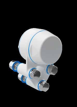
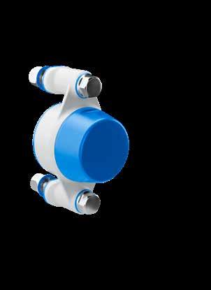
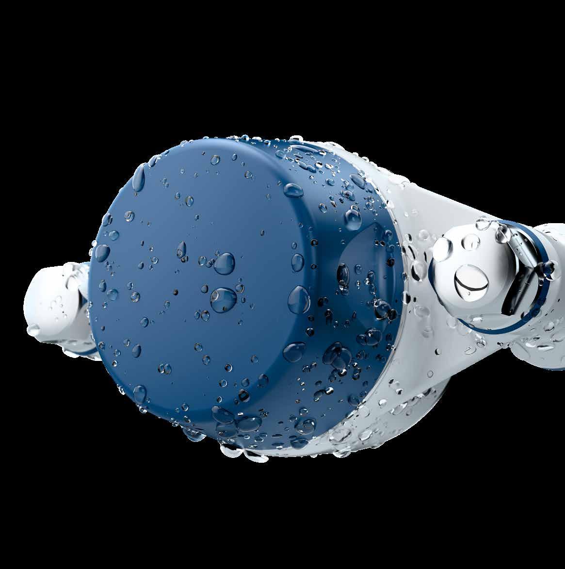
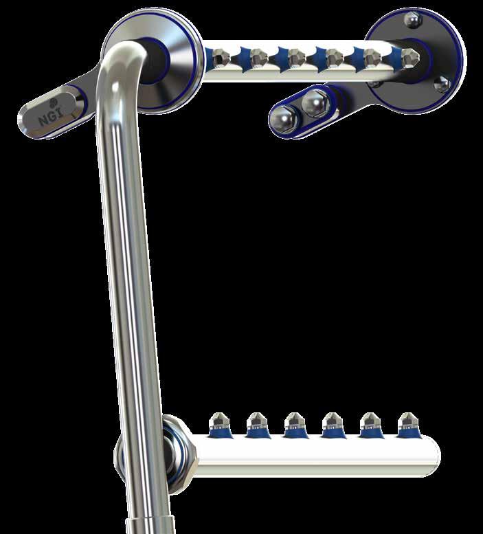
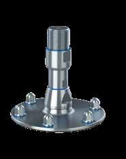
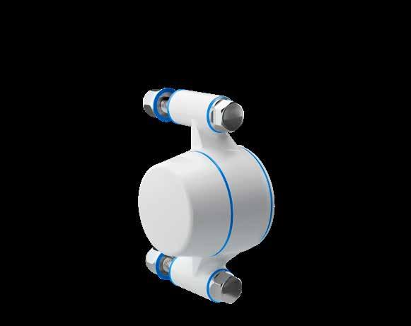
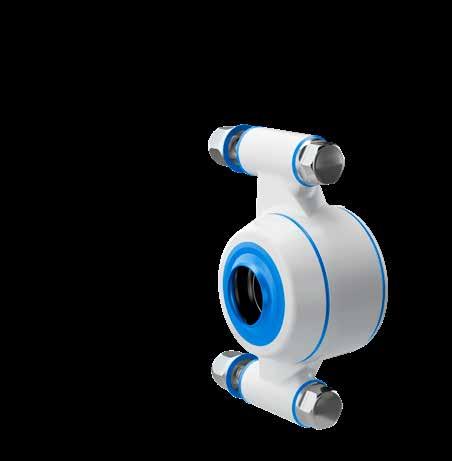
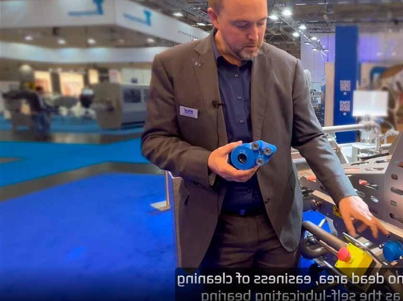
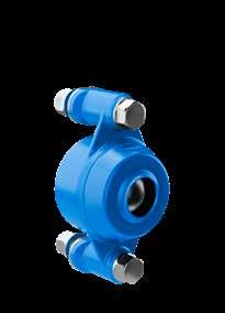
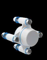
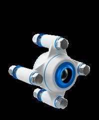
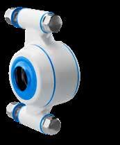
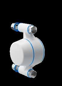
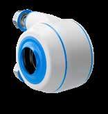
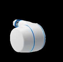
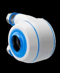
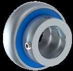
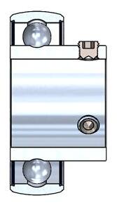
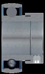
The only patented bearing house in the world hygienically designed and certified by EHEDG, 3-A and USDA standards with extreme easy access for cleaning from all angles.
The bearing house provide a patented waterproof sealing that allows 3 degrees misalignment and can be equipped with a high-performance ceramic bearing lubricated for life with 4-8 times extended lifetime

“We are in the food processing industry where hygiene and sanitation matter most and the high-quality parts from NGI really point towards that providing our customers the possibility of an easy-clean, low maintenance, and high-durability components.
All qualities which customers in the food processing industry are looking for.”
Ulrich Krümpelmann International Sales Manager, Alco-food-machines GmbH & Co. KG, Germany
The hygienic standard of your production equipment is a crucial competitive parameter when it comes to winning an order or being authorized as a new supplier.
Scan the below QR code an watch a video from Alcofood-machines, Mr. Ulrich Krümpelmann, who explains how a component on a food processing machine can have influence on your competitiveness.

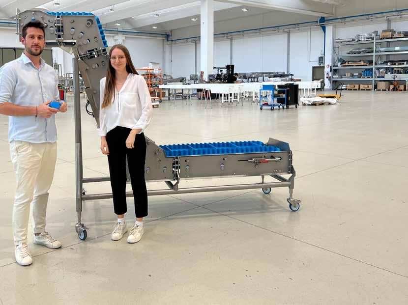

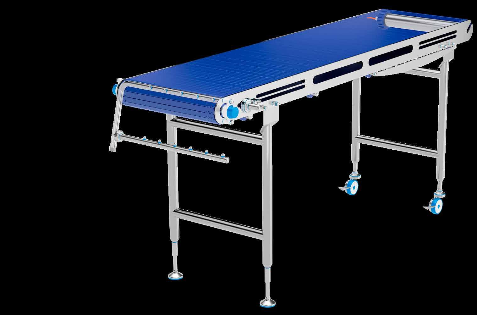
We have interviewed one of our Italian customers in order to learn more about how our customers experience today’s challenges in regard to food safety and higher hygiene. MORC2 is a machine builder and constructs and manufactures conveyors.
You can see the whole testimonial from MORC2 on our website by scanning the QR code below.
Quote“The reasons why we chose NGI bearing houses are mainly their characteristics such as the good quality of the materials, the strength and stability. Another important feature is that they are lubrication free, which is crucial for minimizing the risk of contaminating the machinery.
NGI proves to be a reliable partner in price and performance of their products”.
Lucia Ulinici MORC2 s.r.l. Italy
Below is a conservative example of the Return on Investment of using NGI lubrication-free bearing houses compared to lubricated bearing houses 20 EUR surcharge per bearing house for 400 units and lubrication every two weeks.
Please note that the surcharge will rarely be 20 EUR, and most end-users lubricate more frequently than every two weeks.

• 2/3 of bearing failures are caused by lack of or faulty lubrication. Since the NGI bearings are lubrication-free, the risk of failure is considerably reduced.
• The hygienic design contributes to reducing the emission of water and detergents in the cleaning process thus reducing the environmental impact.
• The lubrication-free bearings eliminate the emission of grease spreading from the bearing to both wastewater and to other parts of the production environment.
Minimized cleaning time Certified hygienic
Minimized water usage
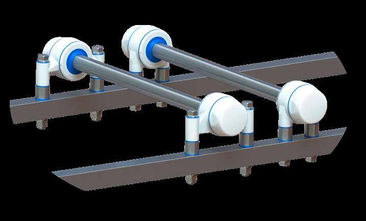
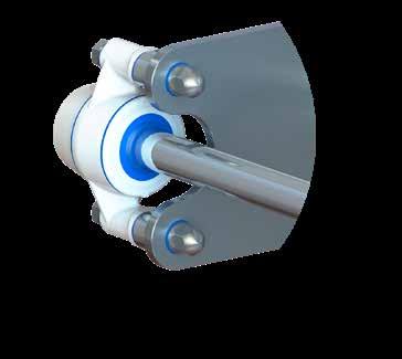
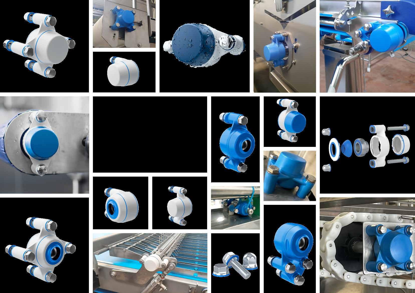
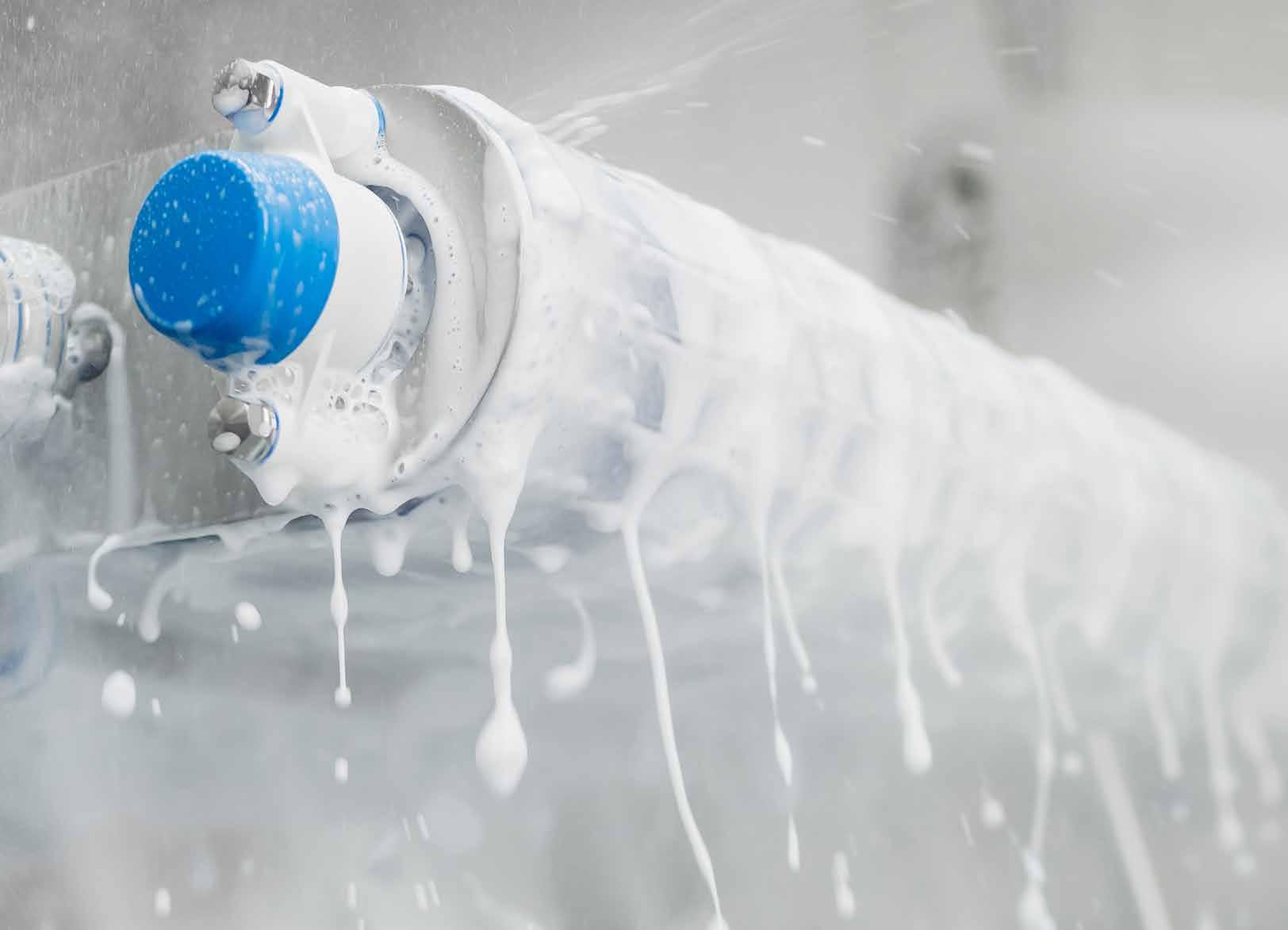
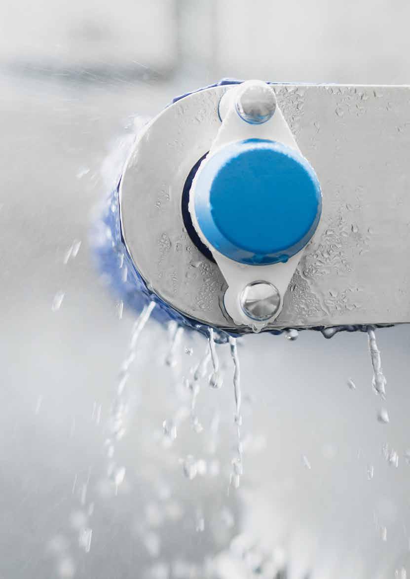
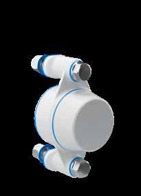
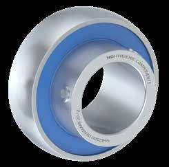
NGI has created a bearing house that is extremely easy to clean fom all angles as water can easily reach all surfaces. All transitions and connections between materials are hygienically sealed with blue sealings.
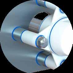
A high focus on hygienic design ensures that the bearing house can be cleaned behind and around the shaft and furthermore, NGI ofers hygienic spacers to increase the distance to machines and equipment to over an inch as recommended by USDA.
Installation is easy and you will be able to use your usual procedure, however, as the bearing can be turned inside the house and covers are replaceable, the bearing house from NGI is far more flexible and can be mounted in more ways than traditional bearing houses.
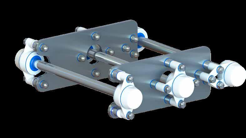
NGI is the only manufacturer in the world of certified hygienic bearing houses designed to comply and certified by EHEDG, 3-A and USDA standards. The product group consists of five different types of bearing houses fitted with ceramic or as standard stainless steel bearings. The bearing houses are designed according to ISO3228_2013 and fit insert bearings that meet ISO9628_2006. This also applies to outside dimensions and it is therefore, a perfect hygienic substitution for an unhygienic solution.
• Easy access for cleaning from all angles
• Flexible mounting - can accomodate initial misalignment
• Fitted with stainless steel bearing or ceramic bearing.
• Tested and conforms to ISO9628_2006 & ISO3228_2013
• Can be supplied with hygienic bolts and nuts as standard. More sizes available upon request.
• Can accomodate temperatures -20oC to +110oC depending on insert bearing
• Unique patented seal system, waterproof at more than 3o misalignment
• Produced in sturdy grilamid with co-moulded FDA-approved TPS seals
• The housing is able to withstand the same dynamic and static radial load as insert bearings
• Housing made from grilamid, a high strength High-performance PA12 and optimized for detection in the food and pharmaceutical industries
Choosing bearing houses from NGI optimized with ceramic spherical ball bearings you will be able to reach optimal quality, robustness and stability. The bearing houses are lubrication free which minimizes maintenance and the need for grease, thereby, minimizing the risk of contaminating the product. Our bearing houses are IP69K-certified.
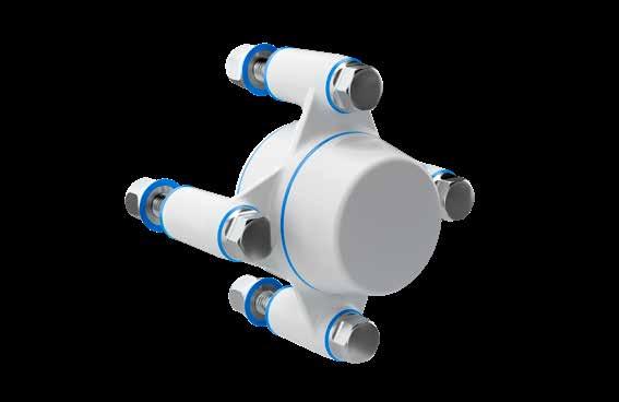
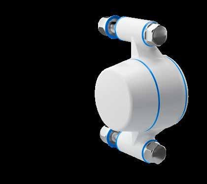
Special Features
- 2-hole flange bearing house
- Mounted parallel to shaft direction
- Shaft diameter 20 mm - 40 mm
- Can be supplied with certified hygienic nuts and bolts for maximum hygienic safety
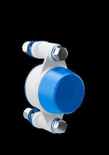
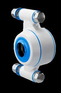
Special Features
- 3-hole flange bearing house
- Mounted parallel to shaft direction
- Shaft diameter 20 mm - 30 mm
- Can be supplied with certified hygienic nuts and bolts for maximum hygienic safety
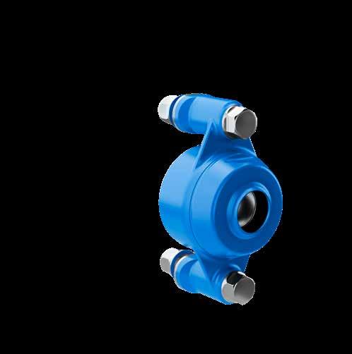
Special Features
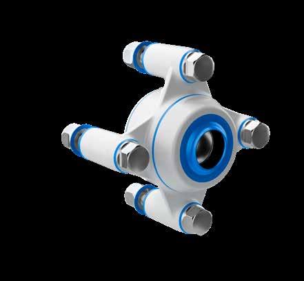
- 4-hole flange bearing house
- Mounted parallel to shaft direction
- Shaft diameter 20 mm - 40 mm
- Can be supplied with certified hygienic nuts and bolts for maximum hygienic safety
• Suitable for heavier or alternating axial load depending on the way it is locked onto the shaft
• For further information on load capacities look at bearing data sheet or contact NGI
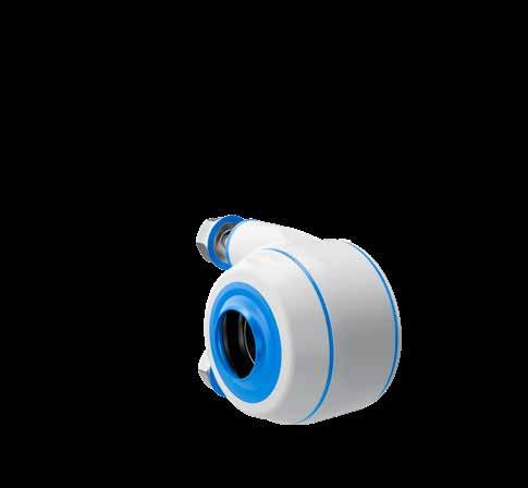
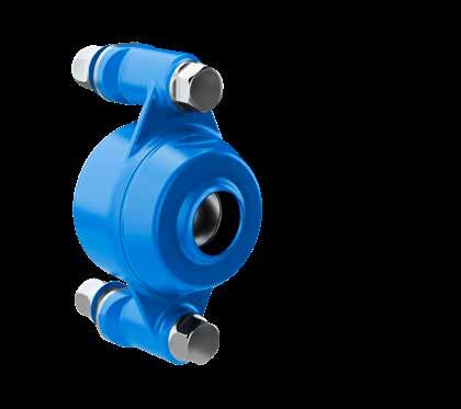
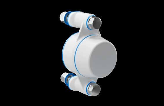
Special Features
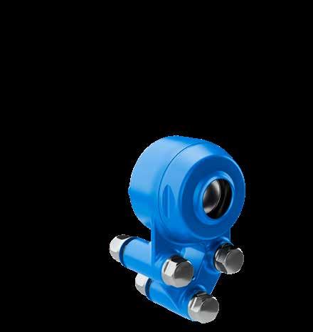
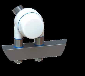
- Pillow block bearing house
- Mounted perpendicularly to shaft direction
- Shaft diameter 20 mm - 35 mm
- Can be supplied with certified hygienic nuts and bolts for maximum hygienic safety
Special Features
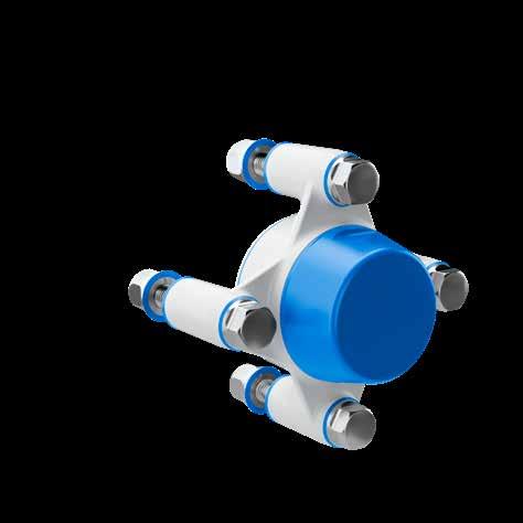
- Tapped base bearing house
- Mounted perpendicularly to shaft direction
- Shaft diameter 25 mm - 30 mm
- Can be supplied with certified hygienic nuts and bolts for maximum hygienic safety
This declaration of conformity lists all the directives and standards that NGI adheres to. This ensures that products from NGI are always in compliance with currently valid requirements.
Minimized cleaning time Certified hygienic
Minimized water usage
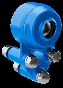
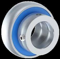
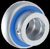
The design and patent protected XB2FC 2-hole flange bearing house is the optimal choice for machinery and equipment that has to comply with strict hygiene requirements
The XB2FC bearing house is mounted parallel to shaft direction
The XB2FC is designed to provide easy access for cleaning from all angles. We recommend that you choose a bearing house with NGI’s hygienic nuts and bolts for maximum hygienic safety.


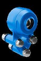
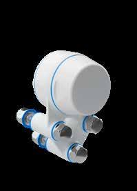
The design and patent protected XB3FC 3-hole flange bearing house is the optimal choice for machinery and equipment that has to comply with strict hygiene requirements.
The XB3FC bearing house is mounted parallel to shaft direction.
The XB3FC is designed to provide easy access for cleaning from all angles. We recommend that you choose a bearing house with NGI’s hygienic nuts and bolts for maximum hygienic safety.
cleaning time
water usage


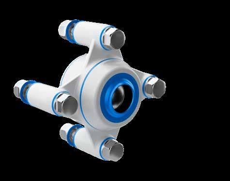
The design and patent protected XB4FC 4-hole flange bearing house is the optimal choice for machinery and equipment that has to comply with strict hygiene requirements.
The XB4FC bearing house is mounted parallel to shaft direction.
The XB4FC is designed to provide easy access for cleaning from all angles. We recommend that you choose a bearing house with NGI’s hygienic nuts and bolts for maximum hygienic safety.
Minimized
Minimized
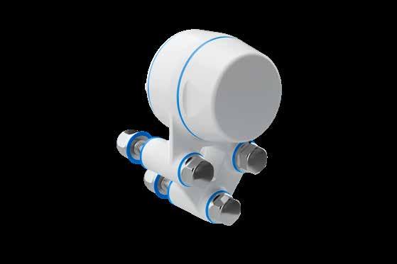
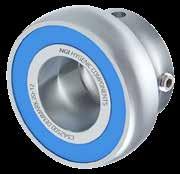
The design and patent protected XBPBC 2-hole block full bearing house is the optimal choice for machinery and equipment that has to comply with strict hygiene requirements.
The XBPBC bearing house is mounted perpendicularly to shaft direction
The XBPBC is designed to provide easy access for cleaning from all angles. We recommend that you choose a bearing house with NGI’s hygienic nuts and bolts for maximum hygienic safety.


The design and patent protected XBTBC block short-base bearing house is the optimal choice for machinery and equipment that has to comply with strict hygiene requirements.
The XBTBC bearing house is mounted perpendicularly to shaft direction
The XBTBC is designed to provide easy access for cleaning from all angles. We recommend that you choose a bearing house with NGI’s hygienic nuts and bolts for maximum hygienic safety.
Minimized cleaning time
Minimized water usage


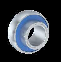
We produce stainless steel and ceramic hybrid high performance insert bearings of the highest quality. Seals are made from FDA blue NBR.
Research based on the analysis of 1.000 bearings shows that 99,6% of ceramic bearings last at least 4 times longer than standard bearings.
In 50% of the cases, the service life of the bearing was between 8-20 times longer than the bearings they replaced.
In 30% of the cases, it is expected that the ceramic bearings will never need to be replaced for the entire service life of the machine.

Certified hygienic
Minimized cleaning time
Minimized water usage


Special Features
- Stainless Steel Bearing
- Stainless steel balls
- AISI 440 rings
Special Features
- Ceramic Bearing
- Hybrid with ceramic balls
- AISI 440 rings
Special Features
- Stainless Steel Bearing
- Stainless steel balls
- AISI 440 rings
- Eccentric locking collar
Special Features
- Ceramic Bearing
- Hybrid with ceramic balls
- AISI 440 rings
- Eccentric locking collar
Our bearings are pre-installed in the bearing houses and we currently offer 4 types - stainless steel or ceramic hybrid bearing with screws or locking collar.
Our certified hygienic bearing houses with IP69K sealing provide the ideal environment for the bearing and are therefore suitable for maintenance-free operation.
The main operating parameters that determine the lifetime of the bearing are bearing type and size, load, speed, operating temperature, shaft tolerances.
Our ball bearings are greased-for-life with high-performance multi-purpose grease designed specifically for the lubrication of food processing machinery all sealed-for-life by seals made from FDA-approved blue NBR.
The locking method with screws is the most common locking function.
Bearings with an eccentric locking collar are intended primarily for use in applications where the direction of rotation is constant. On one side of the bearing inner ring is an eccentric extension that fits the locking collar.

Certified hygienic
Minimized cleaning time
Minimized water usage
collar
With screws
With screws
With screws
With screws
With screws
With locking collar
With locking collar
With locking collar
With locking collar
With locking collar
Grease for bearing balls in stainless steel: Our bearing balls in stainless steel are lubricated-for-life with Mobilgrease FM 222 a high performance multi-purpose products designed specifically for the lubrication of food processing machinery. FM 222 are Agriculture and Agri-Food Canada category n lubricant (incidental food contact) and are formulated with components meeting the requirements of CFR 178.3570, Chapter 21, and NSF registered as H1 classified lubricants.
DIN 51825 KPF2K-20 - Kosher/Parve –Halal.
Grease for bearing balls in ceramic hybrid: Our bearing ball in ceramic hybrid are lubricated-for-life with ROCOL® FOODLUBE Premier 1 a soft, white, non-toxic lubricant containing PTFE for the effective lubrication and protection of ball, roller and plain bearings, slides and bushes particularly those operating in food, pharmaceutical and other clean environments.
FOODLUBE Premier 1 is temperature resistance of -20°C to +180°C and it is manufactured from only FDA listed ingredients: FDA Group 21 CFR 178.3570.
FOODLUBE Premier 1 is NSF registered, NSF H1 registered – 141084 and ISO 21469 certified.
NGI is able to ofer certifed hygienic bolts and nuts with blue NBR rubber seals. The NBR rubber seal blocks out water and bacteria and also prevents a non-hygienic metal-to-metal assembly.
The bolts and nuts have self-draining surfaces with a maximal roughness of 0.8 µm Ra. The design of the bolts and nuts does not deviate from the sizes of current standard bolts and nuts. Therefore, wrench sizes, thread heights etc. all remains the same making it very easy to upgrade and replace standard bolts.
This is the right choice of accessories to be used on all machinery in all certifed hygienic wash-down environments.
- Certifed in accordance with 3-A (RPSCQC)
- Certifed in accordance with EHEDG hygienic standard TYPE EL - CLASS I AUX
- Minimizes cleaning time and water consumption
- Surfaces with a maximal roughness of 0,8 µm Ra
- Available in sizes M5-M24
Certified hygienic
Minimized cleaning time
Minimized water usage
Certified hygienic bolts - BXH
hygienic dome-headed nut - NDXH
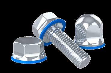
NGI can ofer certifed hygienic spacers with blue NBR rubber seals. The NBR rubber seal blocks out water and bacteria and prevents a non-hygienic metal-to-metal assembly.
A high focus on hygienic design ensures that the bearing house can be cleaned behind and around the shaft and furthermore, NGI ofers hygienic spacers to increase the distance to machines and equipment to over an inch as recommended by USDA.
NGI bearing houses are USDA certifed.
When USDA laws are to be followed use the hygienic spacers from NGI to secure the approved distance to the support surface. For hygienic components from NGI which are already 3-A RPSCQC approved, USDA has mostly been about protection against visible threads and 1“ spacers for bearing housings.
To attach NGI hygienic bearing houses to the support surface always use NGI certifed hygienic bolts or nuts to secure the overall hygienic design.
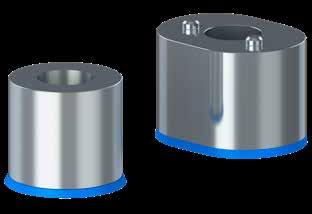
Certified hygienic
Minimized cleaning time
Minimized water usage


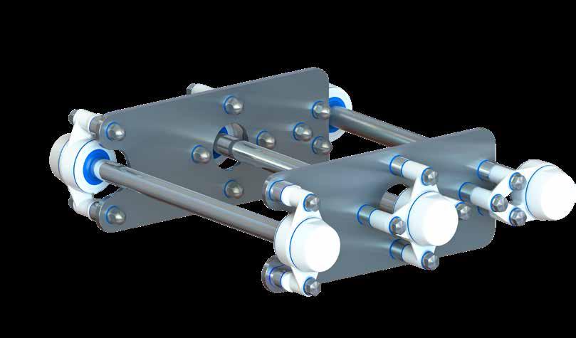
Certified hygienic
Minimized cleaning time
NGI fundamentally adheres to all applicable directives and standards. All information is based on the current state of knowledge and is subject to change. We attentively follow the revisions and amendments to these directives and will design our products accordingly. This ensures that products from NGI are always in compliance with currently valid requirements.
Our product category is not covered by the scope of application of the EC directive for machinery. For this reason, they cannot be furnished with the CE marking in accordance with the EC directive for machinery.
Furthermore, we declare that the listed materials applied in our products comply with the demands for materials used within the food and pharmaceutical industries.
Minimized water usage
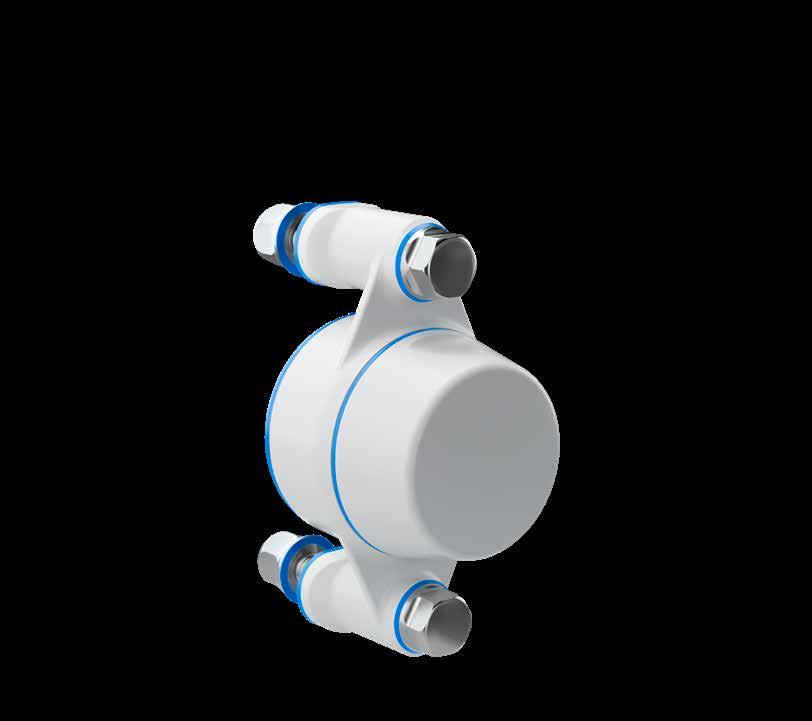
The declaration of materials concerns the following Applications
Application: Insert bearings
Material type: Stainless steel. By request: Ceramic balls NBR rubber seals
Compliance: “Materials and articles to come in contact with food” 1935:2004/EC
This certifcation is based on relevant information supplied by the material manufactures.
Application: Hygienic bolts:
Material type: Stainless steel AISI 316/A4 (A4 (X 5 CrNiMo 17 12 2), Euronorm
Material type bolts 1.4401 EN 10204 TYPE 2.2.
Material type seals Silicon rubber
Compliance: See conformity statement for NGI certifed hygienic bolts
Application: Bearing house & covers
Material type: Grilamid frame, TPS seals
Electrically: Non-conductive
Chemical resistance: High to commonly applied cleaning agents
Color: RAL 9010 (white) body, RAL 5010 (blue) seals
Range of temperature: Min -20°C to Max +125 °C
Storage: According to ISO 2230
Compliance: Mounting according to ISO norm 3228:2013 Bearing compatibility according to ISO norm 9628:2006
FDA: Guideline 21 CFR 177.2600
RoHS 2: In accordance with the Directive 2011/65/EC OF EUROPEAN PARLIAMENT AND OF THE COUNCIL.
European Community: “Materials and articles to come in contact with food” - 1935:2004/EC
“Plastic materials and articles intended to come in contact with food”10:2011/EC
Water resistance: IP69
Water resistant 7 atm or 70 meters.
Scan the code and learn how to replace a bearing house.
You can also fnd detailed guidance in the installation of our bearing houses at www.ngi-global.com
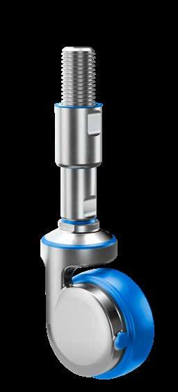
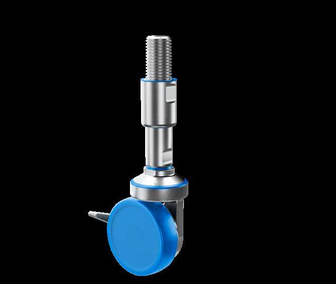
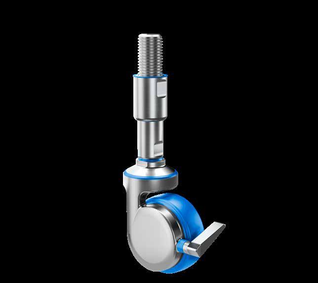
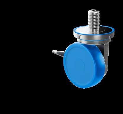
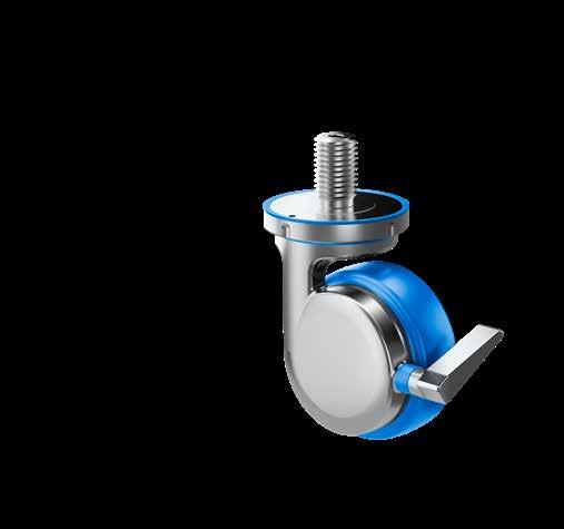
The only patented Castors in the world hygienically designed in accordance to EHEDG, 3-A and USDA standards with easy access for cleaning from all angles
For use in sanitary production environments. self-draining surfaces, completely sealed movable parts and no exposed thread secures absolute minimum cleaning and maximum sanitary safety
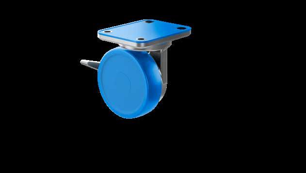
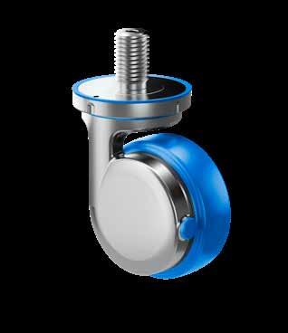
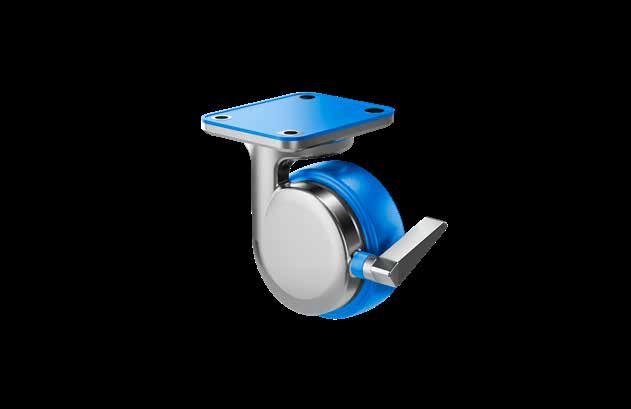
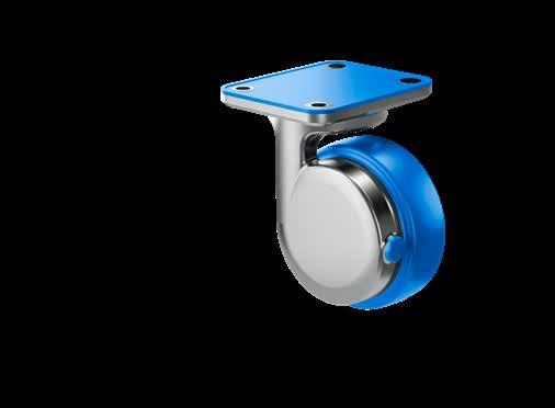
NGI is the only manufacturer in the world of patented castors hygienically designed in accordance with 3-A, EHEDG and USDA design prinicples. The product range consists of three hygienic groups of castors: A castor with a plate fitting, a castor with hygienic levelling spindles and a castor with round thread mounting.
The hygienic castors from NGI have smooth surfaces with soft curves enabling easy access for cleaning. All surfaces are either round or fitted with a 3o angle to provide optimal drainability. Furthermore, the castors are designed for quick and easy installation.

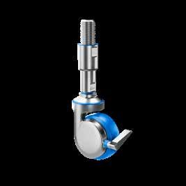
Special Features
- Certified hygienic swivel castor with levelling spindle
- Height variation 224,5 mm - 319,5 mm
- Brake on swivel and wheel
- Extra strong, hardened double roller bearing
- Dynamic castor weight load 2.000 N
• One-sided fork housing providing easy access for cleaning
• Housing made of stainless steel AISI 304/A2 1.4301
• Wheel axle with nut bolt hole
• Center of castor made from white polyamide
• Blue thread made from polyurethane
• Two high quality stainless steel ball bearings
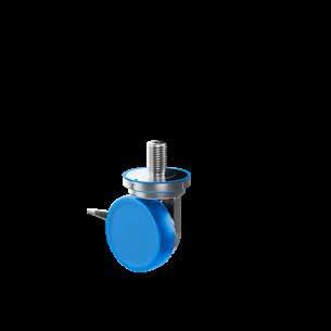
• Wheel dimensions Ø100 (other dimensions to be launched)
• Load capacity tested in accordance to, and conforms to DS/EN12527:1999
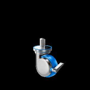
• Developed in accordance to DS/EN12532:1999
Special Features
- Certified hygienic swivel castor
- Extra strong, hardened double roller bearing
- Brake on swivel and wheel
- Dynamic weight load 2.000 N
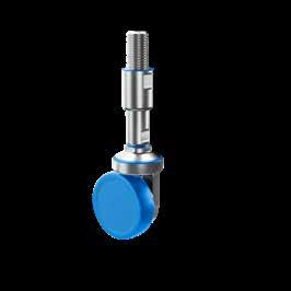
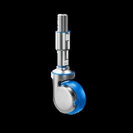
Special Features
- Certified hygienic swivel castor with levelling spindle
- Height variation 224,5 mm - 319,5 mm
- Extra strong, hardened double roller bearing
- Dynamic castor weight load 2.000 N
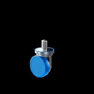

Special Features
- Certified hygienic swivel castor
- Extra strong, hardened double roller bearing
- Dynamic weight load 2.000 N
Special Features
- Certified hygienic castor with levelling spindle
- Rigid swivel
- Height variation 224,5 mm - 319,5 mm
- Dynamic castor weight load 2.000 N
Special Features
- Certified hygienic castor
- Rigid swivel
- Dynamic weight load 2.000 N
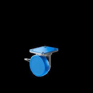
NGI is the only manufacturer in the world of patented castors hygienically designed in accordance with 3-A, EHEDG and USDA design prinicples. The product range consists of three hygienic groups of castors: A castor with a plate fitting, a castor with hygienic levelling spindles and a castor with round thread mounting.
The hygienic castors from NGI have smooth surfaces with soft curves enabling easy access for cleaning. All surfaces are either round or fitted with a 3o angle to provide optimal drainability. Furthermore, the castors are designed for quick and easy installation.
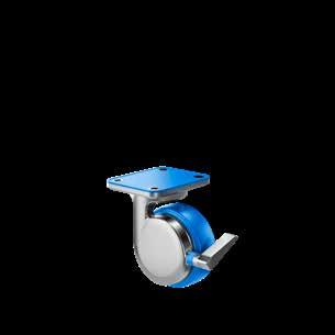
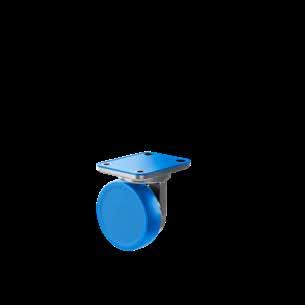
Special Features
- Certified hygienic swivel castor with plate fitting
- Extra strong, hardened double roller bearing
- Brake on swivel and wheel
- Dynamic weight load 2.000 N
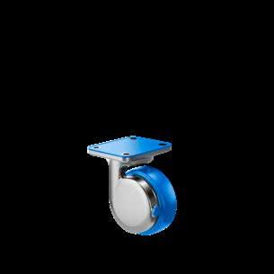
Special Features
- Certified hygienic swivel castor with plate fitting
- Extra strong, hardened double roller bearing
- Dynamic weight load 2.000 N
Special Features
- Certified hygienic castor with plate fitting
- Rigid swivel
- Dynamic weight load up 2.000 N
This declaration of conformity lists all the directives and standards that NGI adheres to. This ensures that products from NGI are always in compliance with currently valid requirements.
- Certified in accordance with EHEDG hygienic standard TYPE EL - CLASS i AUX
- Minimizes cleaning time and water consumption
- Surfaces with a maximal roughness of 0,8 pm RA
- Available in sizes M6-M24
- Are delivered with all certified hygienic machine feet with floor fixing
- Certified in accordance with EHEDG hygienic standard TYPE EL - CLASS i AUX
- Minimizes cleaning time and water consumption
- Surfaces with a maximal roughness of 0,8 pm RA
- Available in sizes M5-M24
- Certified in accordance with EHEDG hygienic standard TYPE EL - CLASS i AUX
- Minimizes cleaning time and water consumption
- Surfaces with a maximal roughness of 0,8 pm RA
- Available in sizes M5-M24
The design and patent protected XSCB-XHS certified hygienic swivel castor with a levelling spindle is the optimal choice for machinery and equipment that has to comply with strict hygiene requirements.
The XSCB-XHS is equipped with a brake on swivel and wheel which is completely integrated in the single-sided fork housing providing accessible surfaces and extreme easy access for cleaning.
The thread on the spindle is covered with a hygienic sleeve which cannot be overadjusted and secures safety against exposed thread.
Spindle parts are 100% hygienically sealed with blue sealings detectable by scanning systems.
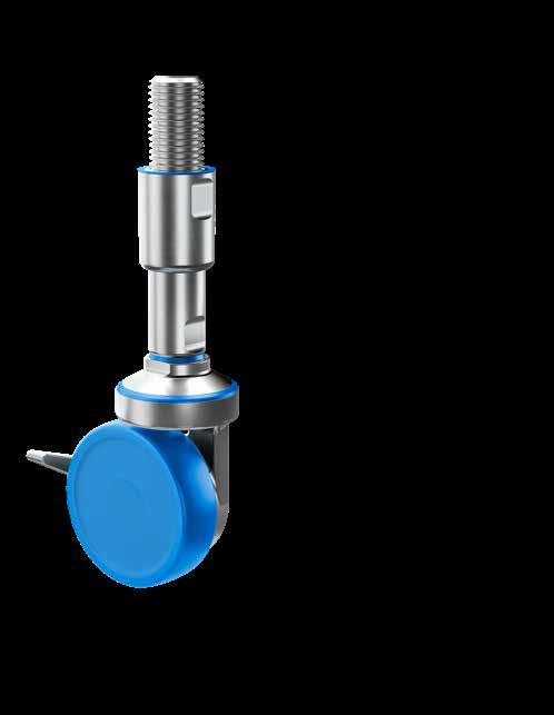
Minimized cleaning time Certified hygienic
Minimized water usage
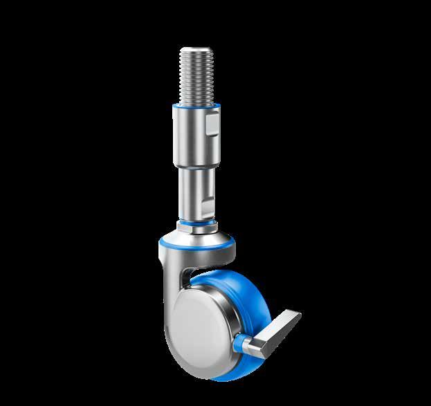
The design and patent protected XSC-XHS certified hygienic swivel castor with a levelling spindle is the optimal choice for machinery and equipment in that has to comply with strict hygiene requirements.
The castors are specifically designed to provide extreme easy access for cleaning and are fitted with smooth, drainable surfaces.
The thread is covered with a hygienic sleeve which cannot be overadjusted and secures safety against exposed thread.
Spindle parts are 100% hygienically sealed with blue sealings detectable by scanning systems.
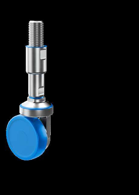
Certified hygienic
Minimized cleaning time
Minimized water usage
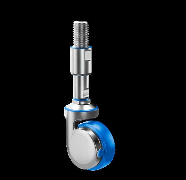
Certified hygienic
Minimized cleaning time
Minimized water usage
The design and patent protected XC-XHS certified hygienic swivel castor with a levelling spindle is the optimal choice for machinery and equipment that has to comply with strict hygiene requirements. The XC-XHS has a rigid swivel.
The thread on the spindle is covered with a hygienic sleeve which cannot be overadjusted and secures safety against exposed thread.
Spindle parts are 100% hygienically sealed with blue sealings detectable by scanning systems.
Certified hygienic
Minimized cleaning time
Minimized water usage
The design and patent protected XSCRB certified hygienic swivel castor is a castor with round thread mounting The XSCRB castor is the optimal choice for machinery and equipment that has to comply with strict hygiene requirements.
The XSCRB is equipped with a brake on swivel and wheel which is completely integrated in the single-sided fork housing providing accessible surfaces and extreme easy access for cleaning.
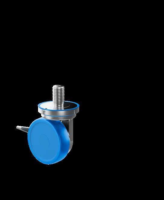
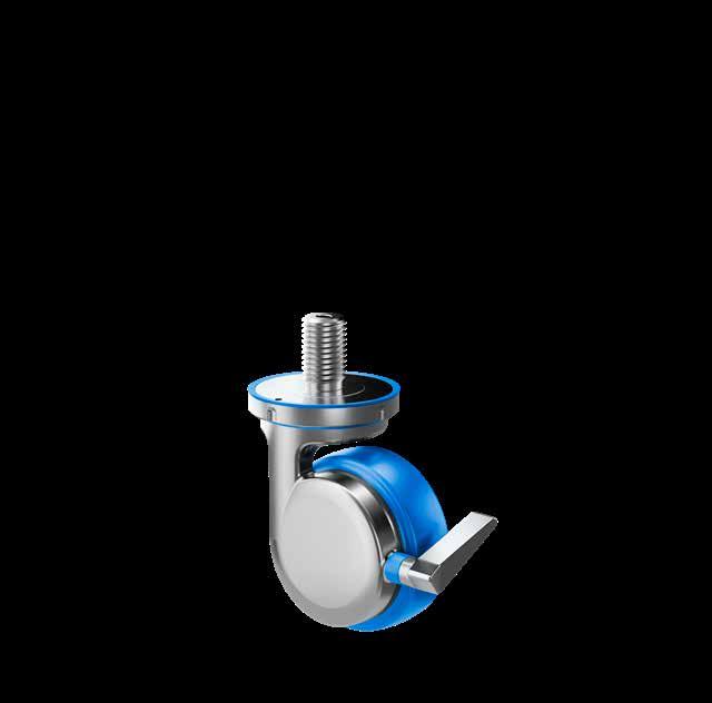
The design and patent protected XSCR certified hygienic swivel castor is a castor with round thread mounting.
The XSCR castor is the optimal choice for machinery and equipment that has to comply with strict hygiene requirements.
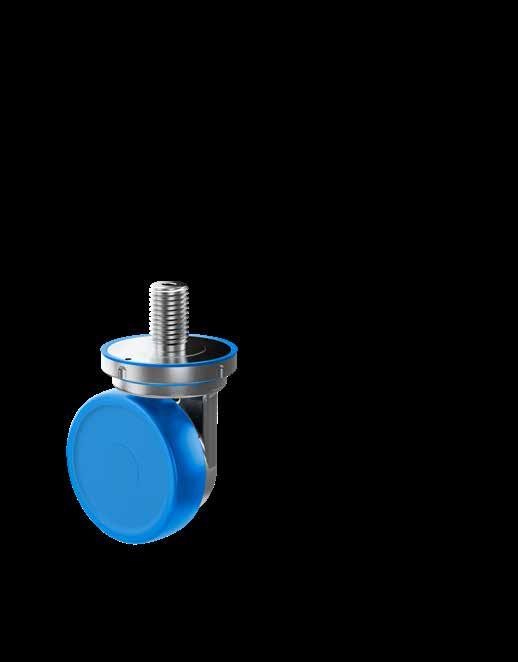
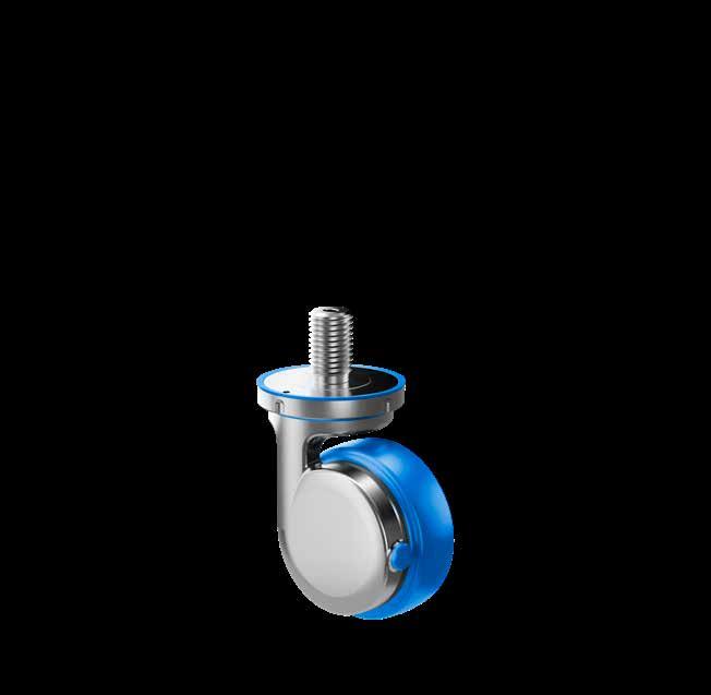
Minimized cleaning time Certified hygienic
Minimized water usage
The design and patent protected XCR certified hygienic swivel castor is a castor with round thread mounting
The XCR castor is the optimal choice for machinery and equipment that has to comply with strict hygiene requirements.
The XCR has a rigid swivel.
Minimized cleaning time Certified hygienic
Minimized water usage
Certified hygienic
Minimized cleaning time
Minimized water usage
The design and patent protected XSCSB certified hygienic swivel castor with plate fitting is the optimal choice for machinery and equipment that has to comply with strict hygiene requirements.
The XSCSB is equipped with a brake on swivel and wheel which is completely integrated in the single-sided fork housing providing accessible surfaces and extreme easy access for cleaning.
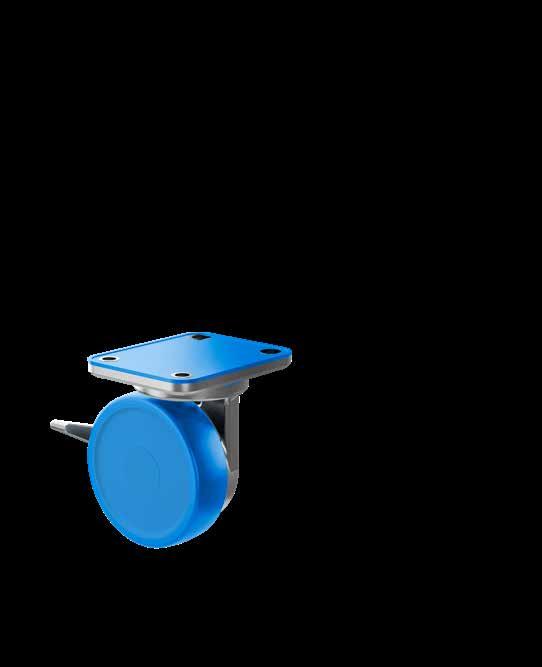
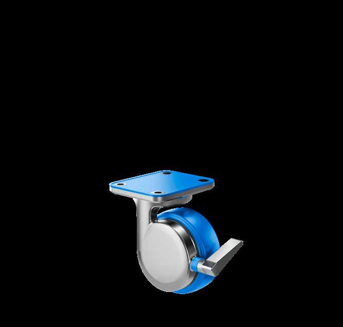
The design and patent protected XSCS certified hygienic swivel castor with plate fitting is the optimal choice for machinery and equipment that has to comply with strict hygiene requirements.
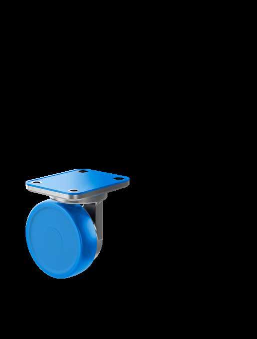
Certified hygienic
Minimized cleaning time
Minimized water usage
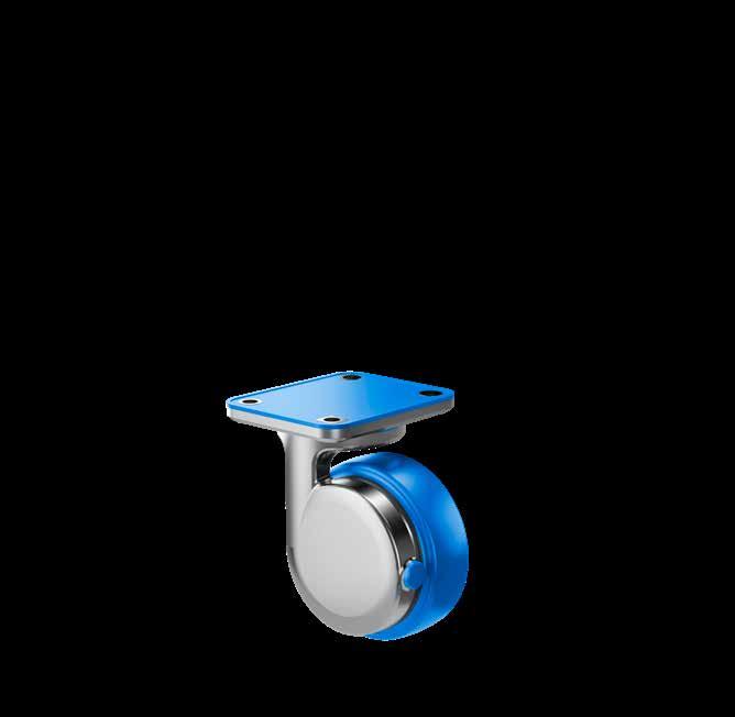
The design and patent protected XCS certified hygienic swivel castor with plate fitting is the optimal choice for machinery and equipment that has to comply with strict hygiene requirements.
The XCS has a rigid swivel.
Minimized cleaning time Certified hygienic
Minimized water usage
NGI fundamentally adheres to all applicable directives and standards. All information is based on the current state of knowledge and is subject to change. We attentively follow the revisions and amendments to these directives and will design our products accordingly. This ensures that products from NGI are always in compliance with currently valid requirements.
Our product category is not covered by the scope of application of the EC directive for machinery. For this reason, they cannot be furnished with the CE marking in accordance with the EC directive for machinery.
Furthermore, we declare that the listed materials applied in our products comply with the demands for materials used within the food and pharmaceutical industries.
Minimized cleaning time Certified hygienic
Minimized water usage
Application: Steel spindle and sleeve
Material type: Stainless steel, AISI 304/A2 (X5CrNi18-10), Euro norm 1.4301.
By request: Stainless steel, AISI 316/A4 (X 5 CrNiMo 17 12 2), Euronorm 1.4401
Compliance: EN 10204 Type 2.2. NGI A/S states that the product is in compliance with the order with indication of results of nonspecific inspection.
NGI A/S has got EN 10204 type 3.1 ins pection certificates on all material used in the products but not specified for each castor.
Application: Castor Body:
Material type steel parts: Stainless steel, AISI 304/A2, Euronorm 1.4301
Compliance: EN 12532:1999
Tested and verified according to EN 12527:1999
NGI states that the parts are in compliance with ISO 9628: 1992. EN 10204 Type 2.2. NGI A/S states that the product is in compliance with the order with indication of results of nonspecific inspection.
NGI has got EN 10204 type 3.1 inspection certificates on all material used in the products but not specified for each castor.

Application: Rolling wheel
Wheel rim: PA, RAL 9010 (white)
Wheel thread: TPU, RAL 5010 (blue)
Compliance: Tested and verified according to EN 12527:1999
RoHS2: In accordance with the Directive 2011/65/EC OF EUROPEAN PARLIAMENT AND OF THE COUNCIL.
European Community: “Materials and articles to come in contact with food” - 1935:2004/EC
“Plastic materials and articles intended to come in contact with food”10:2011/EC
Application: Sealing ring between steel components for NGI’s castors.
Material type: NBR (NNF-75)
Color: Blue
Hardness: 72 ± 3 Shore A DIN 53 505
Range of temperature: Min -35°C to Max +110°C
Compliance:
REACH: In accordance with regulation EC 1907/2006. Do not contain any substances above 0.1% (w/w) from: The Candidate List of Substances of Very High Concern (16.01.2020). Annex XVII (19-11-2019)
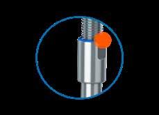
RoHS 2 & RoHS 3 In accordance with the directive 2011/65/EC and 2015/863/EC OF EUROPEAN PARLIAMENT AND OF THE COUNCIL.
ADI free: Does not contain any substances originating from humans or animals.
Bisphenols: Does not contain Bisphenols as described in 1895/2005/EEC. Nor BPA, BADGA, BFDGE or NOGE.
ODS: Does not contain ozone depleting substances. In accordance with the Regulation EC 1005/2009 OF EUROPEAN PARLIAMENT AND OF THE COUNCIL OF 16 SEPTEMBER 2009 and Regulation EC 2037/2000 OF EUROPEAN PARLIAMENT AND OF THE COUNCIL OF 29 JUNE 2000.
Conflict Materials: In accordance with US Law: ”Dodd Frank Wall Street Reform & Consumer Protection Act”, sec. 1502, of 21.07.2010.
GMP: Good manufacturing process in accordance with 2023/2006 EC.
Hazardous materials: Does not contain any hazardous substances as described in the Hong Kong International Convention for the Safe and Environmental. Sound Recycling of ships, 2009.
Phthalates: Does not contain phthalates.
FDA: Guideline 21 CFR 177.2600
This certification is based on relevant information supplied by the material manufacturers
The optimal fully-threaded choice for machinery and equipment in diverse production environments
They offer value-for-money and are available in numerous varieties and functions
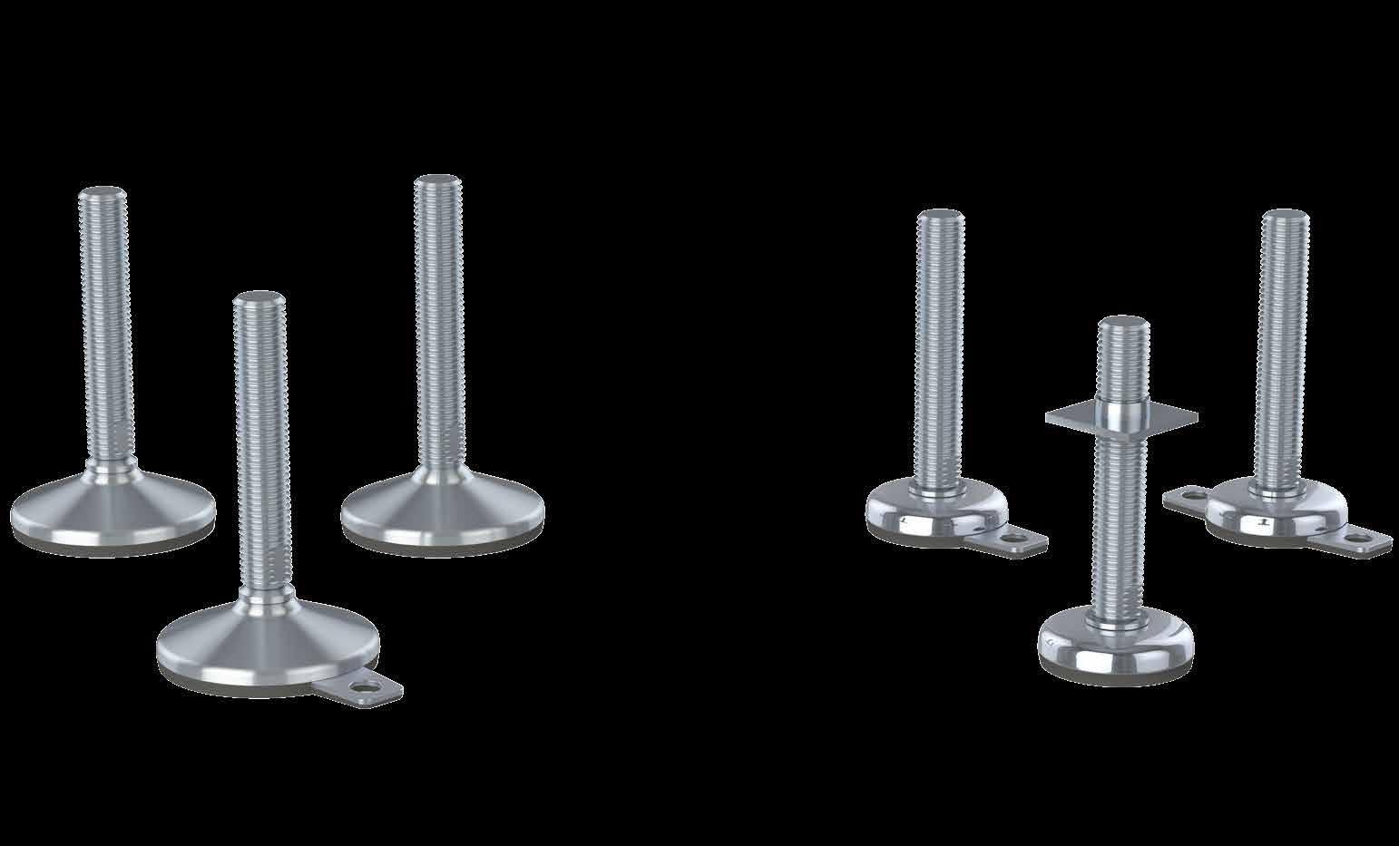
The product group of fully-threaded levelling feet is the optimal choice for machinery and equipment in diverse production environments. Because of the wide variety and functionality these fully-threaded levelling feet ofer great value-for-money and for the majority of the models a hygienic-oriented design because of the self-draining surfaces.
The reliability of the fully-threaded levelling feet has been appreciated by customers world-wide for more than 25 years and the current product portfolio is a result of a continuous innovative approach and market feedback.
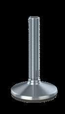
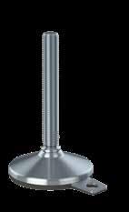
Special Features
- Weight load up to 70.000 N
- Hygienic-oriented design due to self-draining surfaces
- Admits up to 10° slope on floors and equipment
- Optional fxing to the floor
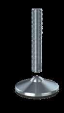
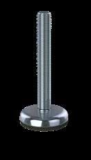
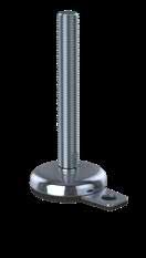
Special Features
- Weight load up to 70.000 N
- Hygienic oriented design due to self-draining surfaces
- The footplate and spindle are two separate parts
- Diametrically centered elevation on the footplate
- Admits up to 15° slope on floors and equipment
- Optional fxing to the floor
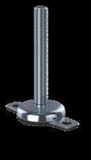
Special Features
- Weight load up to 50.000 N
- Footplate diameters minimum 40 mm – maximum 180 mm
- Admits up to 5° slope on floors and equipment
- Optional single or double fxing to the floor
• Design and patent protected
• Wide variety in footplate design and functionality
• Unlimited customized height variations
• Several thousand diferent variations (weight load, height-adjustment, flexible mounting parts)
• Fully-threaded hygienic oriented levelling feet with self-draining surfaces and limited cleaning efort
• Vulcanized FDA-approved, anti-vibration, anti-slip rubber blocks out bacteria underneath the footplate
• Stainless steel AISI 304/A2, 1.4301. Optional AISI 316/A4, 1.4401
• Low-friction washer between spindle and footplate ensures easy adjustment
• Bolts, nuts, washers, welding plates and plastic bushings can be supplied
This declaration of conformity lists all the directives and standards that NGI adheres to. This ensures that products from NGI are always in compliance with currently valid requirements.
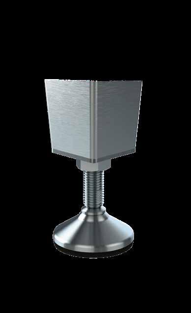
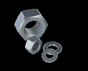
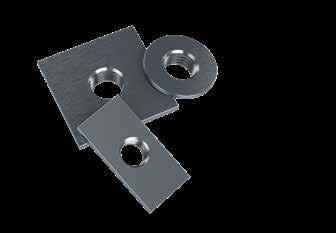
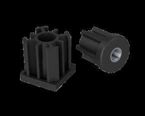
- Stainless steel AISI 304/A2, 1.4301
- Standard nuts (DIN 934)
- Standard counter nuts (DIN 439)
- Standard flat washers (DIN 125)
- Standard fender washers (DIN 9010)
- All dimensions available
- Stainless steel AISI 304/A2, 1.4301
- Squared welding plates
- Round welding plates
- All dimensions available
- Squared plastic bushings
- Round plastic bushings
- Many dimensions available
The design and patent protected HX fully-threaded levelling foot is the optimal choice for machinery and equipment in diverse production environments.
Minimum cleaning efort is obtained by the design of the self-draining surfaces.
Additionally, the foot is hygienically sealed to the floor by vulcanized FDA-approved, anti-vibration, anti-slip rubber, which blocks out bacteria underneath the footplate. FOOT PLATE SPINDLE
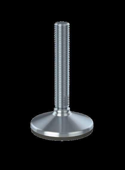
The design and patent protected HX Fixing fully-threaded levelling foot is the optimal choice for machinery and equipment in diverse production environments.
The HX Fixing is designed to be fastened to the floor by the fxing plate. Bolt, nut and washer can be supplied.
Minimum cleaning efort is obtained by the design of the self-draining surfaces.
Additionally, the foot is hygienically sealed to the floor by vulcanized FDA-approved, anti-vibration, anti-slip rubber, which blocks out bacteria underneath the footplate.
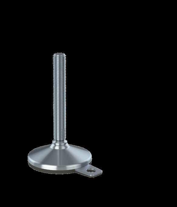
The design and patent protected HXT fully-threaded levelling foot is the optimal choice for machinery and equipment in diverse production environments.
The HXT consists of a separated footplate and spindle connected by the diametrically centered elevation on the footplate.
Minimum cleaning efort is obtained by the design of the self-draining surfaces.
Additionally, the foot is hygienically sealed to the floor by vulcanized FDA-approved, anti-vibration, anti-slip rubber, which blocks out bacteria underneath the footplate.
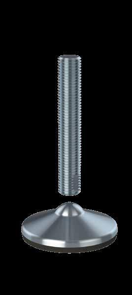
The design and patent protected M fully-threaded levelling foot is the optimal choice for machinery and equipment in diverse production environments.
The wide footplate variety makes the Type M Series applicable to all sizes of machinery and equipment.
Lowered cleaning efort is obtained by the design of the self-draining surfaces.
Additionally, the foot is hygienically sealed to the floor by vulcanized FDA-approved, anti-vibration, anti-slip rubber, which blocks out bacteria underneath the footplate.
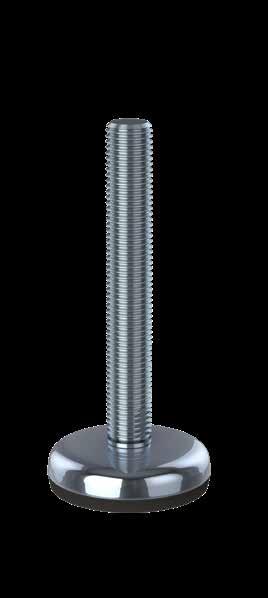
The design and patent protected M Fixing fully-threaded levelling foot is the optimal choice for standardized machinery and equipment in diverse production environments.
The M Fixing is designed to be fastened to the floor by the fxing plate. Bolt, nut and washer can be supplied.
The wide footplate variety makes the Type M Series applicable to all sizes of machinery and equipment.
Lowered cleaning efort is obtained by the design of the self-draining surfaces.
Additionally, the foot is hygienically sealed to the floor by vulcanized FDA-approved, anti-vibration, anti-slip rubber, which blocks out bacteria underneath the footplate.
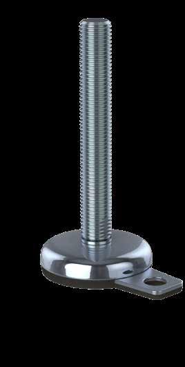
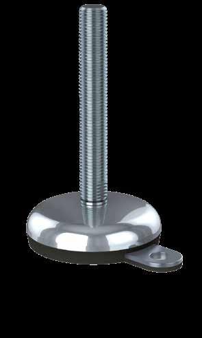
The design and patent protected M Double Fixing fullythreaded levelling foot is the optimal choice for machinery and equipment in diverse production environments.
The M Double Fixing is designed to be fastened to the floor by the two fxing plates. Bolts, nuts and washers can be supplied.
The wide footplate variety makes the Type M Series applicable to all sizes of machinery and equipment.
Lowered cleaning efort is obtained by the design of the selfdraining surfaces.
Additionally, the foot is hygienically sealed to the floor by vulcanized FDA-approved, anti-vibration, anti-slip rubber, which blocks out bacteria underneath the footplate.
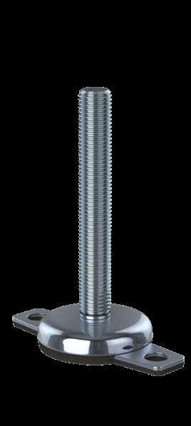
NGI fundamentally adheres to all applicable directives and standards. All information is based on the current state of knowledge and is subject to change. We attentively follow the revisions and amendments to these directives and will design our products accordingly. This ensures that products from NGI are always in compliance with currently valid requirements.
Our product category is not covered by the scope of application of the EC directive for machinery. For this reason, they cannot be furnished with the CE marking in accordance with the EC directive for machinery.
Furthermore, we declare that the listed materials applied in our products comply with the demands for materials used within the food and pharmaceutical industries.
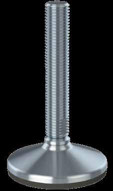
Application: Steel components, e.g. spindle, sleeve and cover for foot
Material type: Stainless steel, AISI 304/A2 (X5CrNi18-10), Euro norm 1.4301.
By request: Stainless steel, AISI 316/A4 (X 5 CrNiMo 17 12 2), Euronorm 1.4401
Compliance: EN 10204 Type 2.2. NGI A/S states that the product is in compliance with the order with indication of results of nonspecifc inspection.
NGI has got EN 10204 type 3.1 inspection certifcates on all material used in the products but not specifed for each foot.
In the directive 94/9/EC, Equipment for potentially explosive atmospheres, also known as the ATEX directive, equipment without its own potential source of ignition are not covered, nor shall be marked according to the directive. However, NGI levelling feet are suitable for use in all ATEX zones.
Application: Foot base for NGI A/S’s hygienic machine feet
Material type: NBR (NNF-75)
Color: Black & blue
Hardness: 72 ± 3 Shore A DIN 53 505
Range of temperature: Min -35°C to Max +110 °C
Compliance:
REACH: In accordance with regulation EC 1907/2006.
Do not contain any substances above 0.1% (w/w) from: The Candidate List of Substances of Very High Concern (16.01.2020). Annex XVII (19-11-2019)
RoHS 2 & In accordance with the Directive 2011/65/EC and 2015/863/EC OF EUROPEAN RoHS 3: PARLIAMENT AND OF THE COUNCIL OF 27 JANUARY.
ADI free: Does not contain any substances originating from humans or animals.
Bisphenols: Does not contain bisphenols as described in 1895/2005/EEC. Nor BPA, BADGA, BFDGE or NOGE.
ODS: Does not contain ozone depleting substances. In accordance with the Regulation EC 1005/2009 OF EUROPEAN PARLIAMENT AND OF THE COUNCIL OF 16 SEPTEMBER 2009 and Regulation EC 2037/2000 OF EUROPEAN PARLIAMENT AND OF THE COUNCIL OF 29 JUNE 2000.
Conflict
Materials: In accordance with US Law: ”Dodd Frank Wall Street Reform & Consumer Protection Act”, sec. 1502, of 21.07.2010.
GMP: Good manufacturing process in accordance with 2023/2006 EC.
Hazardous
Materials: Does not contain any hazardous substances as described in the Hong Kong International Convention for the Safe and Environmental Sound Recycling of ships, 2009.
Phthalates: Does not contain phthalates.
FDA: Guideline 21 CFR 177.2600
The optimal fully-threaded choice for heavy machinery and equipment in diverse production environments
They offer value-for-money and are available in numerous varieties and functions
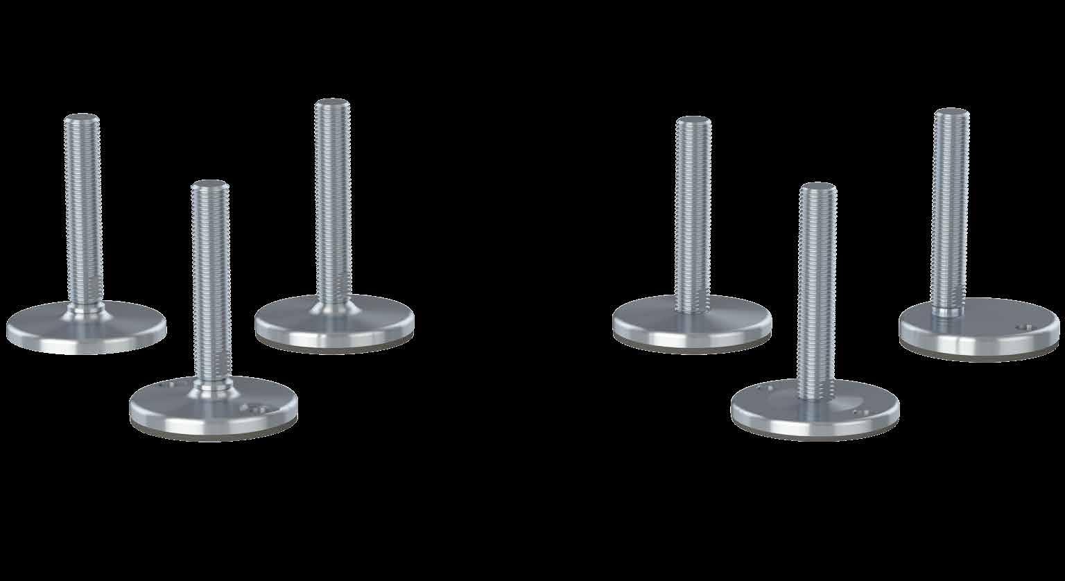
The product group of solid fully-threaded levelling feet is the optimal choice for heavy machinery and equipment in diverse production environments. Because of the wide variety and functionality these solid fully-threaded levelling feet ofer great value-for-money and for the majority of the models a hygienic-oriented design because of the self-draining surfaces.
The reliability of the solid fully-threaded levelling feet has been appreciated by customers world-wide for more than 25 years and the current product portfolio is a result of a continuous innovative approach and market feedback.
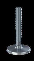
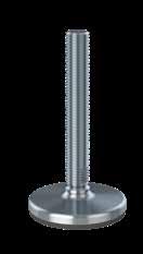
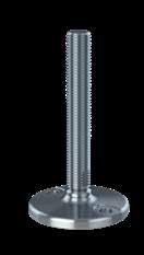
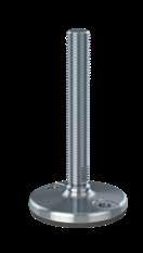
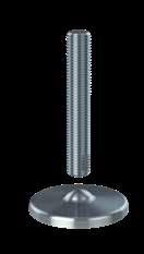
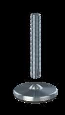
HXG/HXG AS
Special Features
- Footplate diameter Ø105 - Ø125
- Weight load up to 110.000 N
- Hygienic-oriented design due to self-draining surfaces
- Admits up to 9° slope on floors and equipment
- Optional vulcanized, FDA-approved, anti-vibration, anti-slip rubber
• Designed for high load and high pull
• Design and patent protected
• Wide variety in footplate design and functionality
• Unlimited customized height variations
• Several thousand diferent variations (weight load, height-adjustment, flexible mounting parts)
• Solid fully-threaded hygienic oriented levelling feet with self-draining surfaces and limited cleaning efort
• Optional vulcanized FDA-approved, anti-vibration, anti-slip rubber blocks out bacteria underneath the footplate
• Stainless steel AISI 304/A2, 1.4301. Optional AISI 316/A4, 1.4401
• Bolts, nuts, washers, welding plates and plastic bushings can be supplied
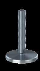
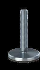
HXJ/HXJ AS
Special Features
- Footplate diameter Ø105 - Ø125
- Weight load up to 110.000 N
- Hygienic-oriented design due to self-draining surfaces
- Admits up to 9° slope on floors and equipment
- Fixing to the floor
- Optional vulcanized, FDA-approved, anti-vibration, anti-sliprubber


HXGT/HXGT AS
Special Features
- Footplate diameter Ø105 - Ø125
- Weight load up to 110.000 N
- Hygienic-oriented design due to self-draining surfaces
- The footplate and spindle are two separate parts
- Diametrically centered elevation on the footplate
- Admits up to 15° slope on floors and equipment
- Optional vulcanized, FDA-approved, anti-vibration, anti-slip rubber
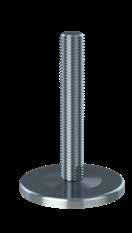
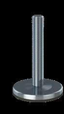
KG/KG AS
Special Features
- Footplate diameter Ø90 - Ø180
- Weight load up to 120.000 N
- Admits up to 8° slope on floors and equipment
- Optional anti-vibration and anti-slip rubber
KJ/KJ AS
Special Features
- Footplate diameter Ø90 - Ø180
- Weight load up to 120.000 N
- Admits up to 8° slope on floors and equipment
- Fixing to the floor
- Optional anti-vibration and anti-slip rubber
G/G AS
Special Features
- Footplate diameter Ø90 - Ø180
- Weight load up to 120.000 N
- Admits up to 1° slope on floors and equipment
- Optional anti-vibration and anti-slip rubber
The product group of solid fully-threaded levelling feet is the optimal choice for heavy machinery and equipment in diverse production environments. Because of the wide variety and functionality these solid fully-threaded levelling feet ofer great value-for-money and for the majority of the models a hygienic-oriented design because of the self-draining surfaces.
The reliability of the solid fully-threaded levelling feet has been appreciated by customers world-wide for more than 25 years and the current product portfolio is a result of a continuous innovative approach and market feedback.
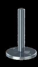
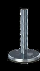
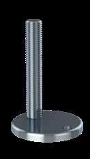
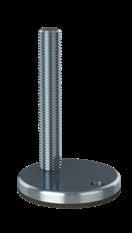
Special Features
- Footplate diameter Ø90 - Ø180
- Weight load up to 120.000 N
- Admits up to 1° slope on floors and equipment
- Fixing to the floor
- Optional anti-vibration and anti-slip rubber
• Designed for high load and high pull
• Design and patent protected
• Wide variety in footplate design and functionality
• Unlimited customized height variations
• Several thousand diferent variations (weight load, height-adjustment, flexible mounting parts)
• Solid fully-threaded hygienic oriented levelling feet with self-draining surfaces and limited cleaning efort
• Optional vulcanized FDA-approved, anti-vibration, anti-slip rubber blocks out bacteria underneath the footplate
• Stainless steel AISI 304/A2, 1.4301. Optional AISI 316/A4, 1.4401
• Low-friction washer between spindle and footplate ensures easy adjustment
• Bolts, nuts, washers, welding plates and plastic bushings can be supplied
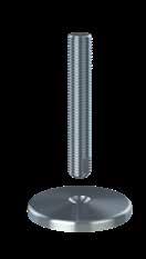
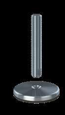
Special Features
- Footplate diameter Ø90 - Ø180
- Weight load up to 200.000 N
- The footplate and spindle are two separate parts
- Diametrically centered depression in the footplate
- Admits up to 20° slope on floors and equipment
- Optional anti-vibration and anti-slip rubber
Special Features
- Footplate diameter Ø110 - Ø180
- Weight load up to 120.000 N
- Decentered spindle in the footplate
- Admits up to 1° slope on floors and equipment
- Fixing to the floor
- Optional anti-vibration and anti-slip rubber
This declaration of conformity lists all the directives and standards that NGI adheres to. This ensures that products from NGI are always in compliance with currently valid requirements.
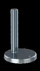
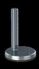
Special Features
- Footplate diameter Ø110
- Weight load up to 100.000 N
- Decentered spindle in the footplate
- Admits up to 8° slope on floors and equipment
- Fixing to the floor
- Optional anti-vibration and anti-slip rubber
- Stainless steel AISI 304/A2, 1.4301
- Standard nuts (DIN 934)
- Standard counter nuts (DIN 439)
- Standard flat washers (DIN 125)
- Standard fender washers (DIN 9010)
- All dimensions available
- Stainless steel AISI 304/A2, 1.4301
- Squared welding plates
- Round welding plates
- All dimensions available
- Squared plastic bushings
- Round plastic bushings
- Many dimensions available
The design and patent protected solid HXG and HXG AS levelling foot is the optimal choice for heavy machinery and equipment in diverse production environments and the most hygienic solid fully-threaded levelling foot.
Reduced cleaning effort is obtained by the hygienic-oriented design with self-draining surfaces.
The joined connection between the spindle and the footplate is designed for high load and high pull, and the low-friction washer between the spindle and footplate ensures easy adjustment under high pressure.
The HXG AS is supplied with vulcanized FDA-approved, anti-vibration, anti-slip rubber, which blocks out bacteria underneath the footplate and creates a hygienic seal to the floor.
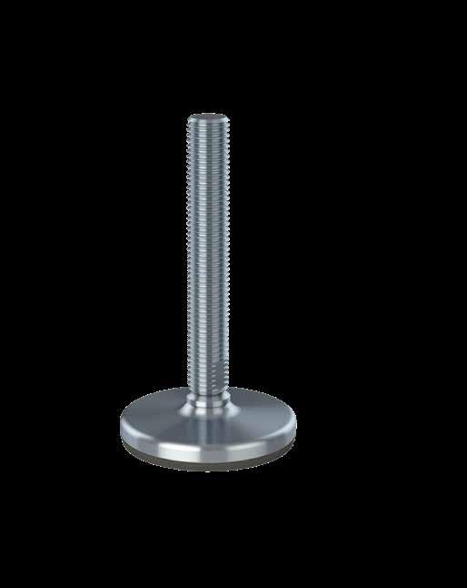

The design and patent protected solid HXJ and HXJ AS levelling foot is the optimal choice for heavy machinery and equipment in diverse production environments.
Reduced cleaning efort is obtained by the hygienic-oriented design with self-draining surfaces.
It is the most hygienic solid fully-threaded levelling foot that can be fastened to the floor by the two fxing holes in the footplate. Bolts, nuts and washers can be supplied.
The joined connection between the spindle and the footplate is designed for high load and high pull, and the low-friction washer between the spindle and footplate ensures easy adjustment under high pressure.
The HXJ AS is supplied with vulcanized FDA-approved, anti-vibration, anti-slip rubber, which blocks out bacteria underneath the footplate and creates a hygienic seal to the floor.
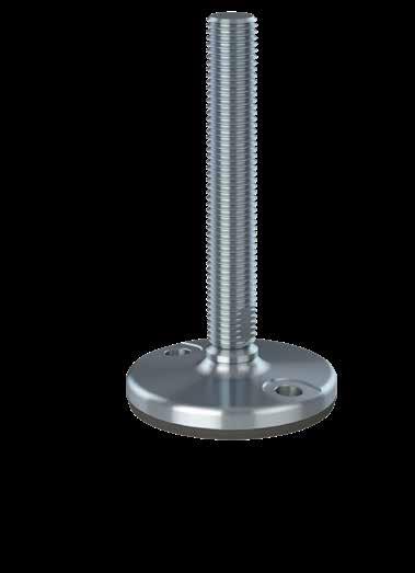
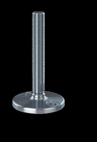
The design and patent protected solid HXGT and HXGT AS levelling foot is the optimal choice for heavy machinery and equipment in diverse production environments and the most hygienic solid fully-threaded levelling foot.
The HXGT and HXGT AS consist of a separated footplate and spindle connected by the diametrically centered elevation on the footplate.
Reduced cleaning efort is obtained by the hygienic-oriented design with self-draining surfaces.
The HXGT AS is supplied with vulcanized FDA-approved, anti-vibration, anti-slip rubber, which blocks out bacteria underneath the footplate and creates a hygienic seal to the floor.
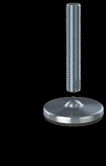
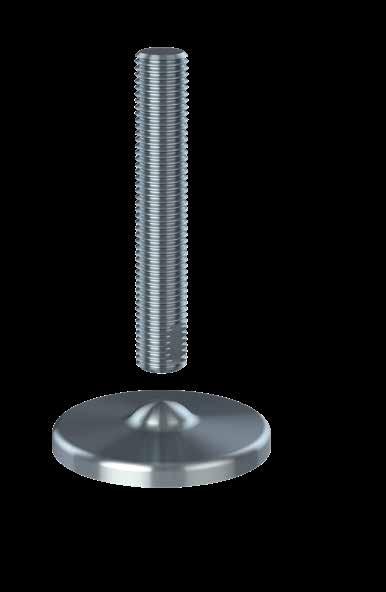
The solid KG levelling foot is the optimal choice for heavy machinery and equipment in diverse production environments.
The joined connection between the spindle and the footplate is designed for very high load and high pull.
The KG AS is supplied with anti-vibration and anti-slip NBR rubber (by request EPDM).
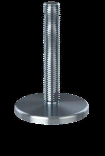
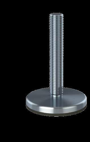
The solid KJ levelling foot is the optimal choice for heavy machinery and equipment in diverse production environments.
The foot can be fastened to the floor by the two fixing holes in the footplate. Bolts, nuts and washers can be supplied.
The joined connection between the spindle and the footplate is designed for very high load and high pull.
The KJ AS is supplied with anti-vibration and anti-slip NBR rubber (by request EPDM).

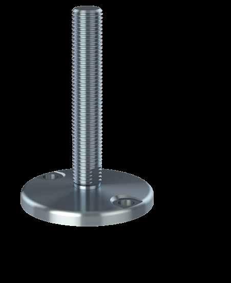
The solid G levelling foot is the optimal choice for heavy machinery and equipment in diverse production environments.
The joined connection between the spindle and the footplate is designed for very high load and high pull and fixed mounting on horisontal surfaces.
The G AS is supplied with anti-vibration and anti-slip NBR rubber (by request EPDM). FOOT PLATE SPINDLE

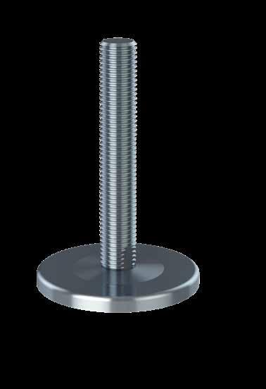
The solid J levelling foot is the optimal choice for heavy machinery and equipment in diverse production environments.
The foot can be fastened to the floor by the two fixing holes in the footplate. Bolts, nuts and washers can be supplied.
The joined connection between the spindle and the footplate is designed for very high load and high pull and fixed mounting on horisontal surfaces.
The J AS is supplied with anti-vibration and anti-slip NBR rubber (by request EPDM).
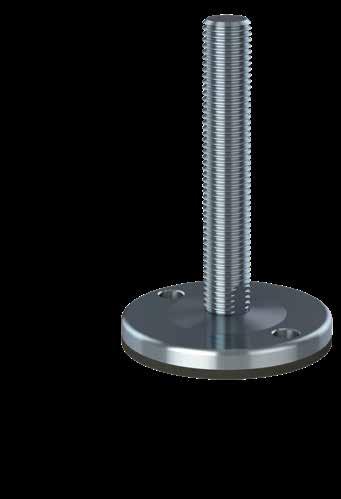
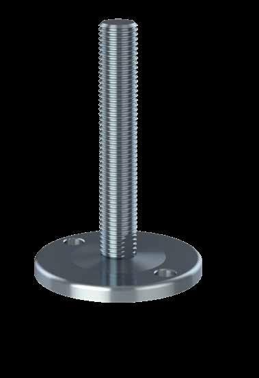
The solid CF levelling foot is the optimal choice for heavy machinery and equipment in diverse production environments.
The foot can easily be fastened to the floor by the decentered fxing hole in the footplate. Bolt, nut and washer can be supplied.
The joined connection between the decentered spindle and the footplate is designed for high load and fxed mounting on horisontal surfaces.
The CF AS is supplied with anti-vibration and anti-slip NBR rubber (by request EPDM).
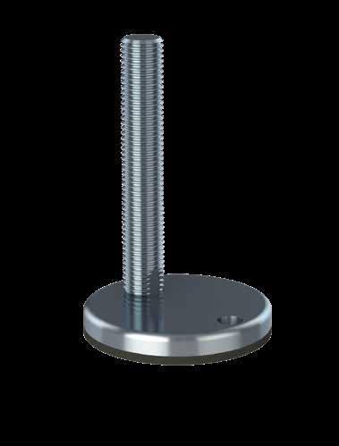
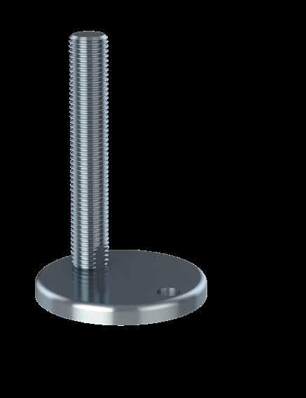
The solid KCF levelling foot is the optimal choice for heavy machinery and equipment in diverse production environments.
The foot can easily be fastened to the floor by the decentered fxing hole in the footplate. Bolt, nut and washer can be supplied.
The joined connection between the decentered spindle and the footplate is designed for high load and flexible mounting on horisontal surfaces.
The KCF AS is supplied with anti-vibration and anti-slip NBR rubber (by request EPDM).
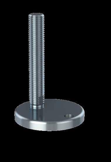

The solid KT levelling foot is the optimal choice for heavy machinery and equipment in diverse production environments.
The KT and KT AS consist of a separated footplate and spindle connected by the diametrically centered depression in the footplate designed for extreme high load.
The KT AS is supplied with anti-vibration and anti-slip NBR rubber (by request EPDM).
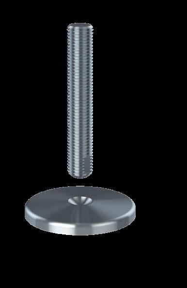
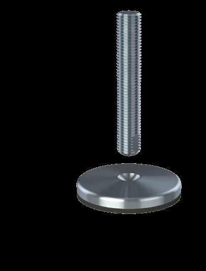
NGI fundamentally adheres to all applicable directives and standards. All information is based on the current state of knowledge and is subject to change. We attentively follow the revisions and amendments to these directives and will design our products accordingly. This ensures that products from NGI are always in compliance with currently valid requirements.
Our product category is not covered by the scope of application of the EC directive for machinery. For this reason, they cannot be furnished with the CE marking in accordance with the EC directive for machinery.
Furthermore, we declare that the listed materials applied in our products comply with the demands for materials used within the food and pharmaceutical industries.
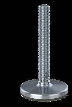
The declaration of materials concerns the following Applications
Application:
Steel components, e.g. spindle, sleeve and cover for foot
Material type: Stainless steel, AISI 304/A2 (X5CrNi18-10), Euro norm 1.4301.
By request: Stainless steel, AISI 316/A4 (X 5 CrNiMo 17 12 2), Euronorm 1.4401
Compliance: EN 10204 Type 2.2. NGI A/S states that the product is in compliance with the order with indication of results of nonspecifc inspection.
NGI A/S has got EN 10204 type 3.1 inspection certifcates on all material used in the products but not specifed for each foot.
In the directive 94/9/EC, Equipment for potentially explosive atmospheres, also known as the ATEX directive, equipment without its own potential source of ignition are not covered, nor shall be marked according to the directive. However, NGI levelling feet are suitable for use in all ATEX zones.
Application: Anti-slip rubber for HXG AS, HXJ AS, HXGT AS and HXJT AS
Material type: NBR (NNF-75)
Color: Black
Hardness: 72 ± 3 Shore A DIN 53 505
Range of temperature: Min -35°C to Max +110°C
Compliance:
REACH: In accordance with regulation EC 1907/2006. Do not contain any substances above 0.1% (w/w) from: The Candidate List of Substances of Very High Concern (16.01.2020). Annex XVII (19-11-2019)
RoHS 2 & RoHS 3: In accordance with the directive 2011/65/EC and 2015/863/EC OF EUROPEAN PARLIAMENT: AND OF THE COUNCIL.
ADI free: Does not contain any substances originating from humans or animals.
Bisphenols: Does not contain Bisphenols as described in 1895/2005/EEC. Nor BPA, BADGA, BFDGE or NOGE.
ODS: Does not contain ozone depleting substances. In accordance with the Regulation EC 1005/2009 OF EUROPEAN PARLIAMENT AND OF THE COUNCIL OF 16 SEPTEMBER 2009 and Regulation EC 2037/2000 OF EUROPEAN PARLIAMENT AND OF THE COUNCIL OF 29 JUNE 2000.
Conflict
Materials: In accordance with US Law: ”Dodd Frank Wall Street Reform & Consumer Protection Act”, sec. 1502, of 21.07.2010.
GMP: Good manufacturing process in accordance with 2023/2006 EC.
Hazardous Does not contain any hazardous substances as described in the Hong materials: Kong International Convention for the Safe and Environmental Sound Recycling of ships, 2009.
Phthalates: Does not contain phthalates.
FDA: Guideline 21 CFR 177.2600
Application: Anti-slip rubber
Material type: NBR By request EPDM
Electrically: Non-conductive
Chemical resistance: High to commonly applied cleaning agents
Color: Black
Hardness: Shore A 80 ± 5
Range of temperature: Min -20 °C to Max 110 °C
Load: Low load capacity
The optimal fully-threaded plastic choice for low- and middle weight machinery and equipment in diverse production environments
They offer value-for-money and are available in numerous varieties and functions
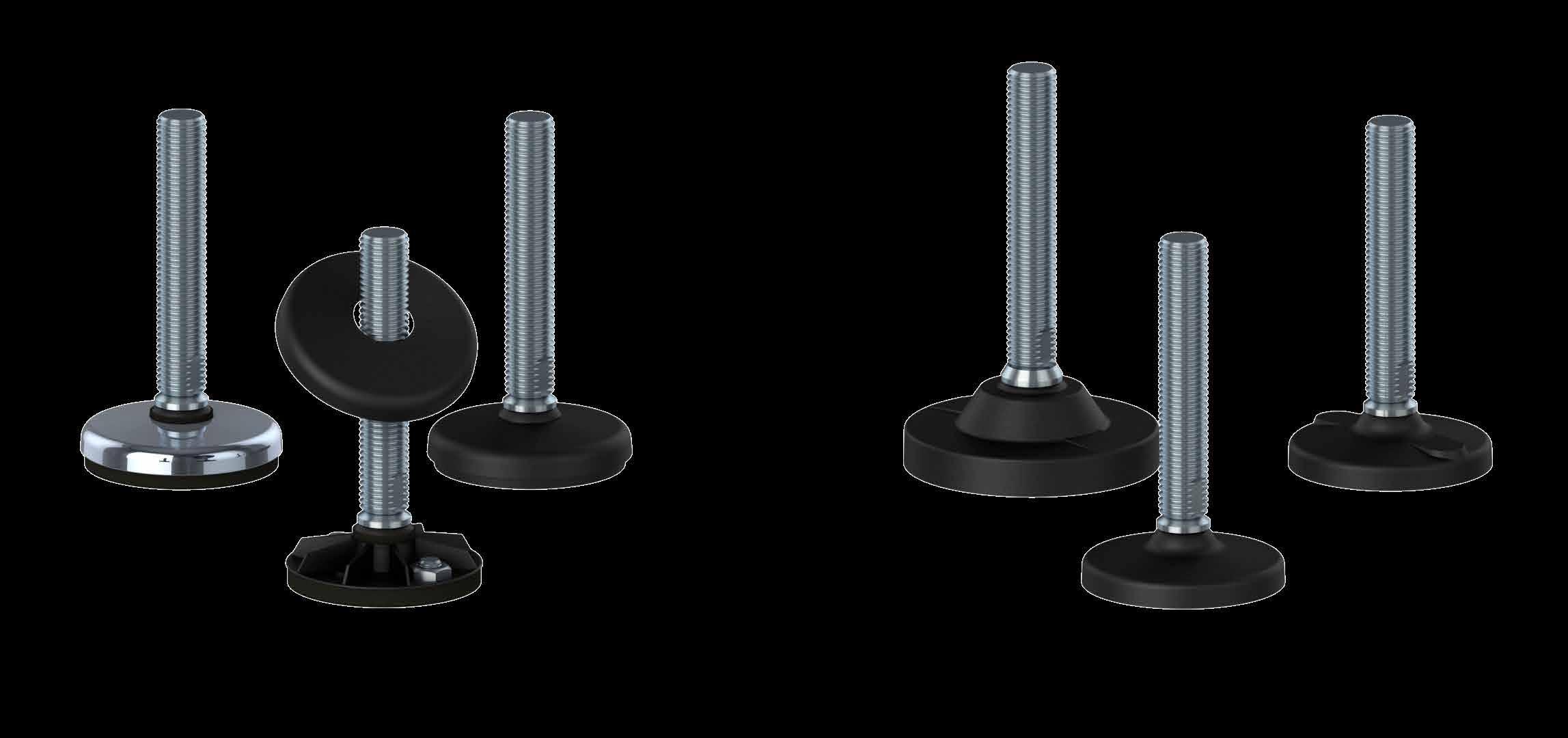
The product group of plastic fully-threaded levelling feet is the optimal choice for low- and middle weight machinery and equipment in diverse production environments. Because of the wide variety and functionality these fully-threaded levelling feet ofer great value-for-money and for the majority of the models a hygienic-oriented design because of the self-draining surfaces.
The reliability of the plastic fully-threaded levelling feet has been appreciated by customers world-wide for more than 25 years and the current product portfolio is a result of a continuous innovative approach and market feedback.
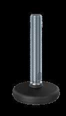
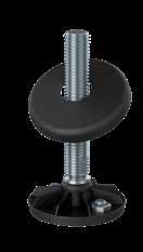
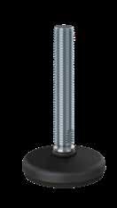
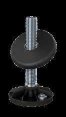

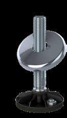
Special Features
- Weight load up to 22.000 N
- Admits up to 10° slope on floors and equipment
- Hygienic-oriented design due to self-draining surfaces
- Possible fastening to the floor under the watertight plastic cap
• Wide variety in footplate design and functionality
• Unlimited customized height variations
• Optional fastening to the floor with sealed fxing holes
• Several diferent variations (weight load, height-adjustment, flexible mounting parts)
• Fully-threaded plastic levelling feet with self-draining surfaces and limited cleaning efort
• Optional anti-vibration and anti-slip rubber
• Spindle in stainless steel AISI 304/A2, 1.4301. Optional AISI 316/A4, 1.4401
• Footplate in reinforced polyamide
• Bolts, nuts, washers, welding plates and plastic bushings can be supplied
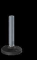
Special Features
- Weight load up to 22.000 N
- Admits up to 10° slope on floors and equipment
- Hygienic-oriented design due to self-draining surfaces
- Embedded anti-slip rubber under footplate
- Possible fastening to the floor under the watertight plastic cap
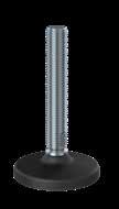
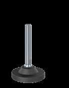
Special Features
- Weight load up to 45.000 N
- Admits up to 10° slope on floors and equipment
- Hygienic-oriented design due to self-draining surfaces
- Optional fastening to the floor under the watertight plastic cap
- Optional anti-slip rubber under footplat
Special Features
- Weight load up to 22.000 N
- Admits up to 10° slope on floors and equipment
- Hygienic-oriented design due to self-draining surfaces
- Embedded anti-slip rubber under footplate
- Possible fastening to the floor under the watertight stainless steel cap
This declaration of conformity lists all the directives and standards that NGI adheres to. This ensures that products from NGI are always in compliance with currently valid requirements.
- Stainless steel AISI 304/A2, 1.4301
- Standard nuts (DIN 934)
- Standard counter nuts (DIN 439)
- Standard flat washers (DIN 125)
- Standard fender washers (DIN 9010)
- All dimensions available
- Stainless steel AISI 304/A2, 1.4301
- Squared welding plates
- Round welding plates
- All dimensions available
- Squared plastic bushings
- Round plastic bushings
- Many dimensions available
The HP plastic fully-threaded levelling foot is the optimal choice for low- and middle weight machinery and equipment in diverse production environments.
It is possible to fasten the levelling foot to the floor by the two pre-drilled fxing holes located under the watertight plastic cap lowering the cleaning efort. Bolts, nuts and washers can be supplied.
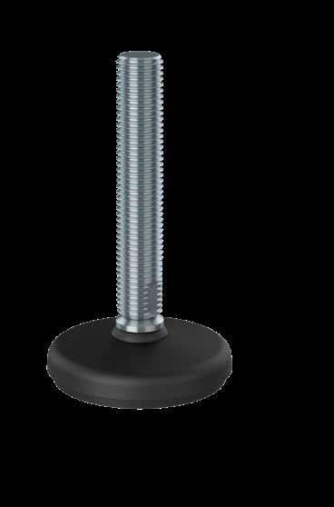
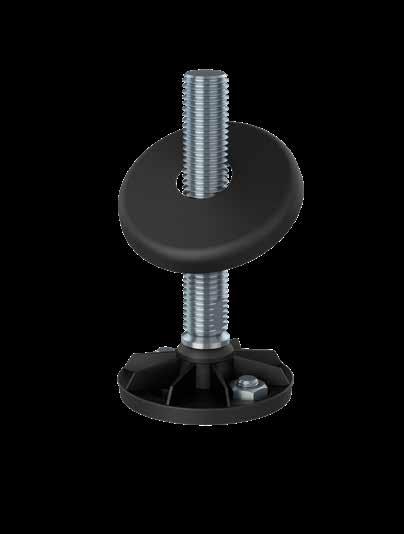
The HPG AS plastic fully-threaded levelling foot is the optimal choice for low- and middle weight machinery and equipment in diverse production environments.
It is possible to fasten the levelling foot to the floor by the two pre-drilled fxing holes located under the watertight plastic cap lowering the cleaning efort. Bolts, nuts and washers can be supplied.
Additionally, the foot is equipped with embedded anti-slip rubber underneath the footplate.
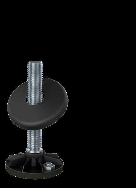
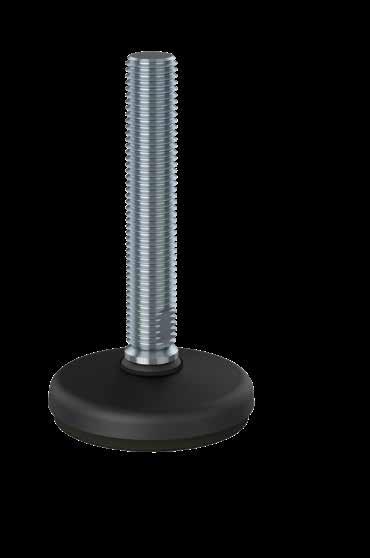
The HPR AS plastic fully-threaded levelling foot is the optimal choice for low- and middle weight machinery and equipment in diverse production environments.
It is possible to fasten the levelling foot to the floor by the two pre-drilled fxing holes located under the watertight stainless steel cap lowering the cleaning efort. Bolts, nuts and washers can be supplied.
Additionally, the foot is equipped with embedded anti-slip rubber underneath the footplate.
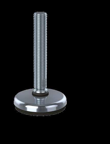
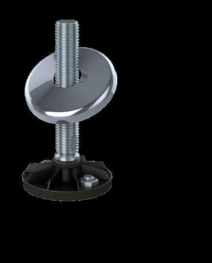
The HPA and HPA AS plastic fully-threaded levelling foot is the optimal choice for low- and middle weight machinery and equipment in diverse production environments.
Lowered cleaning efort is obtained by the design of the self-draining surfaces.
Additionally, the HPA AS is equipped with embedded antislip rubber underneath the footplate.
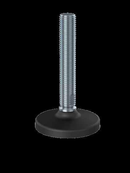
The HPA Fixing and HPA AS Fixing plastic fully-threaded levelling foot is the optimal choice for low- and middle weight machinery and equipment in diverse production environments.
Lowered cleaning efort is obtained by the design of the self-draining surfaces.
It is possible to fasten the levelling foot to the floor by the two pre-pressed fxing holes, which are easily pressed out using a screwdriver. Bolts, nuts and washers can be supplied.
Additionally, the HPA AS Fixing is equipped with embedded anti-slip rubber underneath the footplate.
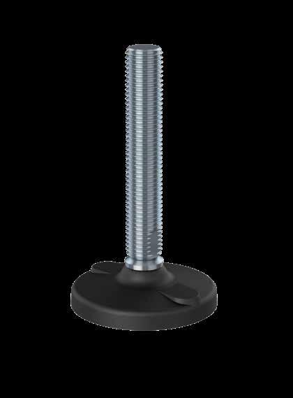
The strong HPA125 and HPA125 AS plastic fully-threaded levelling foot is the optimal choice for heavier machinery and equipment in diverse production environments.
Lowered cleaning efort is obtained by the design of the self-draining surfaces.
It is possible to fasten the levelling foot to the floor by the two pre-pressed fxing holes, which are easily pressed out using a screwdriver. Bolts, nuts and washers can be supplied.
Additionally, the HPA125 AS is equipped with embedded antislip rubber underneath the footplate.

NGI fundamentally adheres to all applicable directives and standards. All information is based on the current state of knowledge and is subject to change. We attentively follow the revisions and amendments to these directives and will design our products accordingly. This ensures that products from NGI are always in compliance with currently valid requirements.
Our product category is not covered by the scope of application of the EC directive for machinery. For this reason, they cannot be furnished with the CE marking in accordance with the EC directive for machinery.
Furthermore, we declare that the listed materials applied in our products comply with the demands for materials used within the food and pharmaceutical industries.
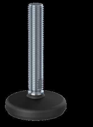
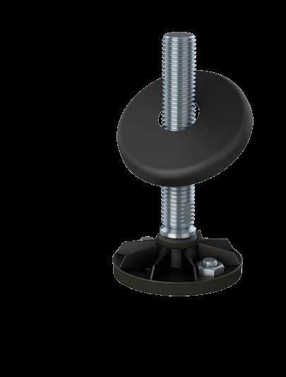
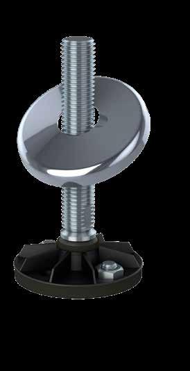
The declaration of materials concerns the following Applications
Application: Steel components, e.g. spindle and cover for foot
Material type: Stainless steel, AISI 304/A2 (X5CrNi18-10), Euronorm 1.4301.
By request: Stainless steel, AISI 316/A4 (X 5 CrNiMo 17 12 2), Euronorm 1.4401
Compliance: EN 10204 Type 2.2. NGI A/S states that the product is in compliance with the order with indication of results of nonspecifc inspection.
NGI has got EN 10204 type 3.1 inspection certifcates on all material used in the products but not specifed for each foot.
In the directive 94/9/EC, Equipment for potentially explosive atmospheres, also known as the ATEX directive, equipment without its own potential source of ignition are not covered, nor shall be marked according to the directive. However, NGI levelling feet are suitable for use in all ATEX zones.
Application: Footbase for NGI A/S’s machinefeet and cover for foot
Material type: PA 6 Miramid FP, reinforced.
Electrically: Non-conductive.
IP Code IP69K: DIN (Deutsches Institut für Normung) 40050-9: Straßenfahrzeuge; IP-Schutzarten; Schutz gegen Fremdkörper, Wasser und Berühren; Elektrische Ausrüstung [Road vehicles; degrees of protection (IP-code); protection against foreign objects, water and impact; electrical equipment]. May 1993. (an English translation of the German original is available from DIN).
Chemical resistance: High to commonly applied cleaning agents.
Color: Black
Flammability 94 HB
Range of temperature: Min -20°C to Max +110°C Max. temperature High thermal resistance for short duration: +150°C
Compliance:
REACH: In accordance with regulation EC 1907/2006. Do not contain any substances above 0.1% (w/w) from: The Candidate List of Substances of Very High Concern (16.01.2020). Annex XVII (19-11-2019)
RoHS 2 & RoHS 3: In accordance with the Directive 2011/65/EC and 2015/863/EC OF THE EUROPEAN PARLIAMENT AND OF THE COUNCIL.
ADI free: Does not contain any substances originating from humans or animals.
Bisphenols: Does not contain bisphenols as described in 1895/2005/EEC. Nor BPA, BADGA, BFDGE or NOGE.
ODS: Does not contain ozone depleting substances. In accordance with the Regulation EC 1005/2009 OF EUROPEAN PARLIAMENT AND OF THE COUNCIL OF 16 SEPTEMBER 2009 and Regulation EC 2037/2000 OF EUROPEAN PARLIAMENT AND OF THE COUNCIL OF 29 JUNE 2000.
Conflict
Materials: In accordance with US Law: ”Dodd Frank Wall Street Reform & Consumer Protection Act”, sec. 1502, of 21.07.2010.
GMP: Good manufacturing process in accordance with 2023/2006 EC.
Hazardous
materials: Do not contain any hazardous substances as described in the Hong Kong International Convention for the Safe and Environmental Sound Recycling of ships, 2009. Phthalates: Does not contain phthalates.
The declaration of materials concerns the following Applications
Application: Plastic Lid
Material type: PPC
Electrically: Non-conductive
Chemical resistance: High to commonly applied cleaning agents
Color: Black
Hardness: Rockwell R 85
Range of temperature: Min -20 °C to Max 90 °C
Load: High load capacity
Application: Anti slip
Material type: NBR By request EPDM
Electrically: Non-conductive
Chemical resistance: High to commonly applied cleaning agents
Color: Black
Hardness: Shore A 80 ± 5
Range of temperature: Min -20 °C to Max 110 °C
Load: Low load capacity
Application: Anti slip 2K Bounded
Material type: TPE
Electrically: Non-conductive
Chemical resistance: High to commonly applied cleaning agents
Color: Black
Hardness: Shore A 90 ± 5
Range of temperature: Min -50°C to Max +125 °C
Load: High load capacity
Application: Sealing ring between steel components for NGI’s machine feet.
Material type: Silicon rubber
Electrically: Non-conductive
Chemical resistance: High to commonly applied cleaning agents
Color: RAL 5010 (blue)
Hardness: Shore A 60 ± 5
Range of temperature: Min -60°C to Max +200 °C
Storage: According to ISO 2230
Compliance:
FDA: Guideline 21 CFR 177.2600
RoHS 2: In accordance with the Directive 2011/65/EC OF EUROPEAN PARLIAMENT AND OF THE COUNCIL.
GMP: Good manufacturing process in accordance with 2023/2006 EC.
The only weighing levelling feet in the world with build in standard weighing cell secured, guided and protected inside the feet
The design and patent protected ngi weighing levelling feet is the optimal choice for supporting and easy weihing of machinery, equipment, tanks and vessels

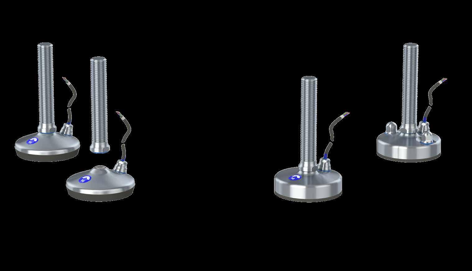
The design and patent protected NGI Weighing levelling feet is the optimal choice for supporting and easy weighing of machinery, equipment, tanks and vessels.
NGI weighing levelling feet are optimized for the PR 6251 PanCake load cell family to guarantee best weighing performance and a very compact construction, unmatched reliability, robustness and stability, which enable trouble-free operation without adjustment, year after year.
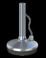
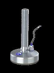
Special Features
- Maximum weight load 5 ton
- Spindle sizes M20, M24, M30 & M36
- Footplate sizes Ø80, Ø105, Ø125 & Ø150 mm
- Hygienic-oriented design due to self-draining surfaces
- Admits up to 5° slope on floors and equipment
- Vulcanized FDA-approved, anti-vibration, anti-slip rubber blocks out bacteria underneath the footplate and protects the load cell
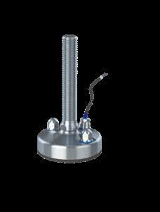

Special Features
- Footplate diameter Ø105 & Ø150 mm
- Hygienic-oriented design due to self-draining surfaces
- Admits up to 5o slope on floor and equipment
- Top cover with blue sealing detectable by scanning systems
- Ensures hygienic covering of the exposed top
- Available in standardized and customized dimensions
- Optional fxing to the floor
Special Features
- Maximum weight load 5 ton
- Spindle sizes M16, M20, M24, M30 & M36
- Footplate sizes Ø80, Ø105, Ø125 & Ø150mm
- Hygienic-oriented design due to self-draining surfaces
- The footplate and spindle are two seperate parts
- Admits up to 10° slope on floors and equipment
- Vulcanized FDA-approved, anti-vibration, anti-slip rubber blocks out bacteria underneath the footplate and protects the load cell
• Plug n’ play height-adjustable compact design
• One-point impact between load cell and spindle ensures direct and friction free transfer of force
• Stainless steel AISI 304/A2, 1.4301. Optional AISI 316/A4, 1.4401
• All movable parts are 100% hygienically sealed even if the load on the foot is removed
• All sealing are blue and therefore detectable by scanning systems

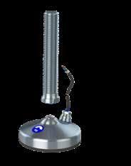
Special Features
- Maximum weight load 5 ton
- Spindle sizes M16, M20, M24, M30 & M36
- Footplate sizes Ø105 & Ø150 mm
- Hygienic-oriented design due to self-draining surfaces
- The footplate and spindle are two seperate parts
- Admits up to 10° slope on floors and equipment
This declaration of conformity lists all the directives and standards that NGI adheres to.
This ensures that products from NGI are always in compliance with currently valid requirements.
The design and patent protected HXW weighing levelling foot is the optimal choice for supporting and weighing machinery, equipment, tanks and vessels. The load cell is secured, guided and protected inside the foot.
- Secured: Load cell is secured against hazardous mechanical external impacts
- Guided: Can obtain strong forces in all directions without afecting the load cell
- Protected: Against external influences like corrosion, temperatures and bacteria
The HXW levelling foot is hygienically sealed to the floor by vulcanized FDA-approved, anti-vibration, anti-slip rubber, which blocks out bacteria underneath the footplate and protects the load cell.
- Maintenance free and height-adjustable compact design
- Simple and fast installation - no mounting kit needed
- The diferent load cells cover a span of 30kg to 5000 kg
- Stainless steel AISI 304/A2, 1.4301. Optional AISI 316/A4, 1.4401
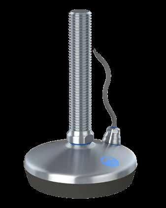
The design and patent protected HXGW weighing levelling foot is the optimal choice for supporting and weighing machinery, equipment, tanks and vessels. The load cell is secured, guided and protected inside the foot.
- Secured: Load cell is secured against hazardous mechanical external impacts
- Guided: Can obtain strong forces in all directions without afecting the load cell
- Protected: Against external influences like corrosion, temperatures and bacteria
The HXGW levelling foot is hygienically sealed to the floor by rubber sealing which blocks out bacteria underneath the footplate and protects the load cell.
- Maintenance free and height-adjustable compact design
- Simple and fast installation - no mounting kit needed
- The diferent load cells cover a span of 30 kg to 5.000 kg
- Stainless steel AISI 304/A2, 1.4301. Optional AISI 316/A4, 1.4401
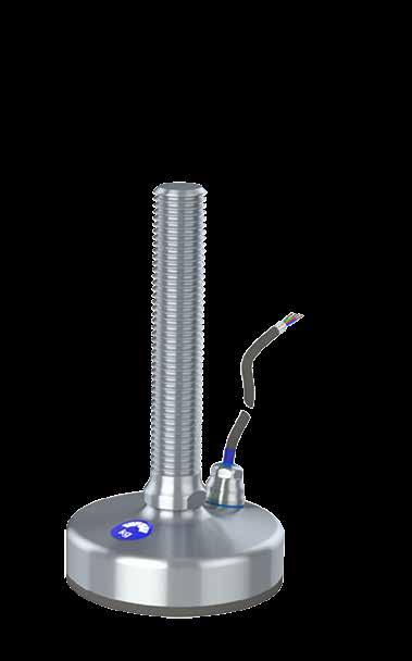
The design and patent protected HXJW weighing levelling foot is the optimal choice for supporting and weighing machinery, equipment, tanks and vessels.The load cell is secured, guided and protected inside the foot.
- Secured: Load cell is secured against hazardous mechanical external impacts
- Guided: Can obtain strong forces in all directions without afecting the load cell
- Protected: Against external influences like corrosion, temperatures and bacteria
The HXJW is designed to be fastened to the floor by the two fxing holes in the footplate.
The HXJW levelling foot is hygienically sealed to the floor by rubber sealing which blocks out bacteria underneath the footplate and protects the load cell.
- Maintenance free and height-adjustable compact design
- Simple and fast installation - no mounting kit needed
- The diferent load cells cover a span of 30 kg to 5.000 kg
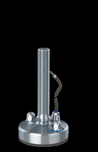
- Stainless steel AISI 304/A2, 1.4301. Optional AISI 316/A4, 1.4401
The design and patent protected HXTW weighing levelling foot is the optimal choice for supporting and weighing machinery, equipment, tanks and vessels. The load cell is secured, guided and protected inside the foot.
- Secured: Load cell is secured against hazardous mechanical external impacts
- Guided: Can obtain strong forces in all directions without afecting the load cell
- Protected: Against external influences like corrosion, temperatures and bacteria
The HXTW consists of a separated footplate and spindle connected by the diametrically centered elevation on the weighing footplate. Additionally, the levelling foot is hygienically sealed to the floor by vulcanized FDA-approved, anti-vibration, anti-slip rubber, which blocks out bacteria underneath the footplate and protects the load cell.
- Maintenance free and height-adjustable compact design
- Simple and fast installation - no mounting kit needed
- The diferent load cells cover a span of 30 kg to 5000 kg
- Stainless steel AISI 304/A2, 1.4301. Optional AISI 316/A4, 1.4401
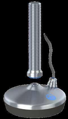
The design and patent protected HXGTW weighing levelling foot is the optimal choice for supporting and weighing machinery, equipment, tanks and vessels. The load cell is secured, guided and protected inside the foot.
- Secured: Load cell is secured against hazardous mechanical external impacts
- Guided: Can obtain strong forces in all directions without afecting the load cell
- Protected: Against external influences like corrosion, temperatures and bacteria
The HXGTW consists of a separated footplate and spindle connected by the diametrically centered elevation on the weighing footplate. The HXGTW levelling foot is hygienically sealed to the floor by rubber sealing which blocks out bacteria underneath the footplate and protects the load cell.
- Maintenance free and height-adjustable compact design
- Simple and fast installation - no mounting kit needed
- The diferent load cells cover a span of 30 kg to 5.000 kg
- Stainless steel AISI 304/A2, 1.4301. Optional AISI 316/A4, 1.4401
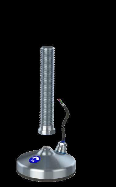


NGI A/S fundamentally adheres to all applicable directives and standards. All information is based on the current state of knowledge and is subject to change. We attentive follow the revisions/amendments to these directives and will design our products accordingly. This ensures that products from NGI A/S are always in compliance with currently valid requirements.
Our type of products is not covered by the scope of application of the EC directive on machinery. For this reason, they cannot be furnished with the CE marking in accordance with the EC directive on machinery.
NGI A/S, Virkelyst 3-7, 9400 Nørresundby, hereby declare that the listed materials applied for the products comply with the demands for materials used within the food and pharmaceutical industry.
Furthermore, we declare that the listed materials applied for the products comply with the demands for materials used within the food and pharmaceutical industries.
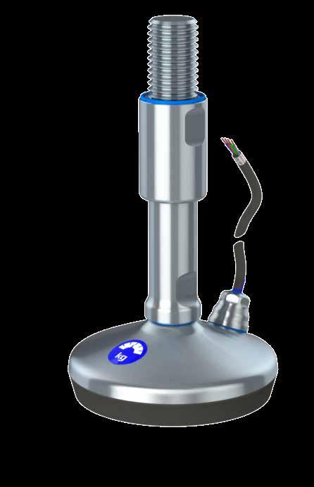
Metallic surfaces are constructed from Stainless steel, AISI 304/A2 or by request Stainless steel, AISI 316/A4 and are corrosion resistant under the specifed conditions of use including those of cleaning.
The elastomeric components are constructed from FDA approved NBR and silicone material. All materials used are considered non-toxic and are non-absorbent.
All exposed metallic surfaces are fnished to maximum surface roughness values of 1.6 pm Ra. All elastomeric components and sealing washers are left as molded with no hand trimming and all surfaces are considered smooth enough to ensure that cleaning is easy.
There are no exposed dissimilar metal-to-metal contact areas in the construction where galvanic corrosion could occur.
Sealing designs permit access for easy cleaning with no inaccessible pockets or crevices.
There are no risk of exposed threads and no unsealed metal-to-metal joints in the fnished construction.
All exposed surfaces have a smooth fnish such that soil may be cleaned from the surface using manual cleaning techniques and be free of pits, folds, cracks, crevices, and other imperfections in the fnal fabricated form.
Drainability and Installation
The units are designed to be self-draining and contain no horizontal ledges.
Comprehensive instructions are provided containing detailed information to ensure compliance with the 3-A and EHEDG design criteria, when the product is certifed.
The 3-A Sanitary Standard 88-00 requires that when machine leveling feet or supports are properly mounted on the equipment, they shall provide a minimum clearance between the lowest part of the equipment and the floor of not less than 4.0 in. (102 mm) if the equipment outlines an area in which no point is more than 12.5 in. (318 mm) from its nearest edge. If the equipment outlines an area in which any point is more than 12.5 in. (318mm) from its nearest edge the clearance shall be at least 6 in. (152mm).
The EHEDG guideline recommends a minimum clearance between the equipment and the floor or wall of 300mm for easy cleaning and inspection.
When fasteners are required, only domed head screws and dome headed nuts must be used. The exposed interfaces shall be sealed with sealing washers and there must be no threads exposed in the installed confguration of the machine feet.
Minimized cleaning time Certified hygienic
Minimized water usage
Foot bases can be sealed to the floor if required. The instructions make recommendations not to span over floor imperfections or grout lines without the addition of proper sealing compounds.
Maximum torque values are specifed as appropriate on fastening arrangements to avoid over-compression of sealing washers and gaskets.
Maintenance instructions are clearly defned and prohibit the use of non-genuine replacement parts.
Cleaning instructions describe typical cleaning procedures with recommended maximum temperatures/pressures and stipulate the use of non-abrasive cleaning aids.
The design does not contain dead spaces and avoid accumulation of soil, microorganism’s insects and other vermin in areas which cannot be easily cleaned.
Sealing and thread locking compounds used in the construction are non-toxic in the cured state.
No lubricants, insulation material or signal transfer liquids are used in the construction.
Standards and directives
EN 1672-2:2005 Food machinery / General design principles/Part 2: Hygiene requirements.
EN ISO 14 159 2004 Safety of machinery – Hygiene requirements for the design of machinery.
Document 13 EHEDG guideline on the hygienic design of apparatus for open processes.
Similar NGI designs meets the criteria for Hygienic Equipment Class I for components situated in the non-food area and are accessible for easy cleaning without dismantling.
The weighing levelling feet design is according to 3-A Sanitary Standard for Machine Leveling Feet and Supports.
Certifed according to USDA Guidelines “Dairy Equipment and NSF ANSI 3-A 14159-1-2014” for the sanitary design and fabrication.
EU regulations
852/2004 on the hygiene of foodstufs.
853/2004 specifc hygiene rules for food of animal origin.
854/2004 specifc rules for the organization of official controls on products of animal origin intended for human consumption.
1935/2004 on materials and articles intended to come into contact with food
The declaration of materials concerns the following Applications
Application: STEEL COMPONENT
Material type: Stainless steel, AISI 304/A2 (X5CrNi18-10), Euro norm 1.4301. By request: Stainless steel, AISI 316/A4 (X 5 CrNiMo 17 12 2), Euronorm 1.4401
Compliance: EN 10204 Type 2.2. NGI A/S states that the product is in compliance with the order with indication of results of nonspecifc inspection.
NGI A/S has got EN 10204 type 3.1 inspection certifcates on all material used in the products but not specifed for each foot.
In the directive 94/9/EC, Equipment for potentially explosive atmospheres, also known as the ATEX directive, equipment without its own potential source of ignition are not covered, nor shall be marked according to the directive. However, NGI levelling feet are suitable for use in all ATEX zones.
Application: Vulcanized antislip rubber foot base (for 0-5 ton)
Material type: NBR (NNF-75)
Color: Black
Hardness: 72 ± 3 Shore A DIN 53 505
Range of temperature: Min -35°C to Max +110°C
Load: Low load capacity
Compliance:
REACH: In accordance with regulation EC 1907/2006. Do not contain any substances above 0.1% (w/w) from: The Candidate List of Substances of Very High Concern (16.01.2020). Annex XVII (19-11-2019)
RoHS 2 & RoHS 3 In accordance with the directive 2002/95/EC OF EUROPEAN PARLIAMENT AND OF THE COUNCIL OF 27 JANUARY.
ADI free: Does not contain any substances originating from humans or animals.
Bisphenols: Does not contain Bisphenols as described in 1895/2005/EEC. Nor BPA, BADGA, BFDGE or NOGE.
ODS: Does not contain ozone depleting substances. In accordance with the Regulation EC 1005/2009 OF EUROPEAN PARLIAMENT AND OF THE COUNCIL OF 16 SEPTEMBER 2009 and Regulation EC 2037/2000 OF EUROPEAN PARLIAMENT AND OF THE COUNCIL OF 29 JUNE 2000.
Conflict: In accordance with US Law: ”Dodd Frank Wall Street Reform & Consumer
Materials: Protection Act”, sec. 1502, of 21.07.2010.
GMP: Good manufacturing process in accordance with 2023/2006 EC.
Hazardous
materials: Does not contain any hazardous substances as described in the Hong Kong International Convention for the Safe and Environmental. Sound Recycling of ships, 2009.
Phthalates: Does not contain phthalates.
FDA: Guideline 21 CFR 177.2600
Application: Sealing ring
Material type: Silicon rubber
Electrically: Non-conductive
Chemical resistance: High to commonly applied cleaning agents
Hardness: Shore A 60 ± 5
Color: RAL 5010 (blue)
Range of temperature: Min -60°C to Max +200°C
Storage: According to ISO 2230
Compliance: FDA: Guideline 21 CFR 177.2600
RoHS 2: In accordance with the Directive 2011/65/EC OF EUROPEAN PARLIAMENT AND OF THE COUNCIL.
GMP: Good manufacturing process in accordance with 2023/2006 EC.

The only seismic levelling feet in the world designed and calculated according to the international new zealand seismic standard
The NGI seismic foot is capable of withstanding earthquakes due to its ability to withstand combinations of vertical and horizontal loads
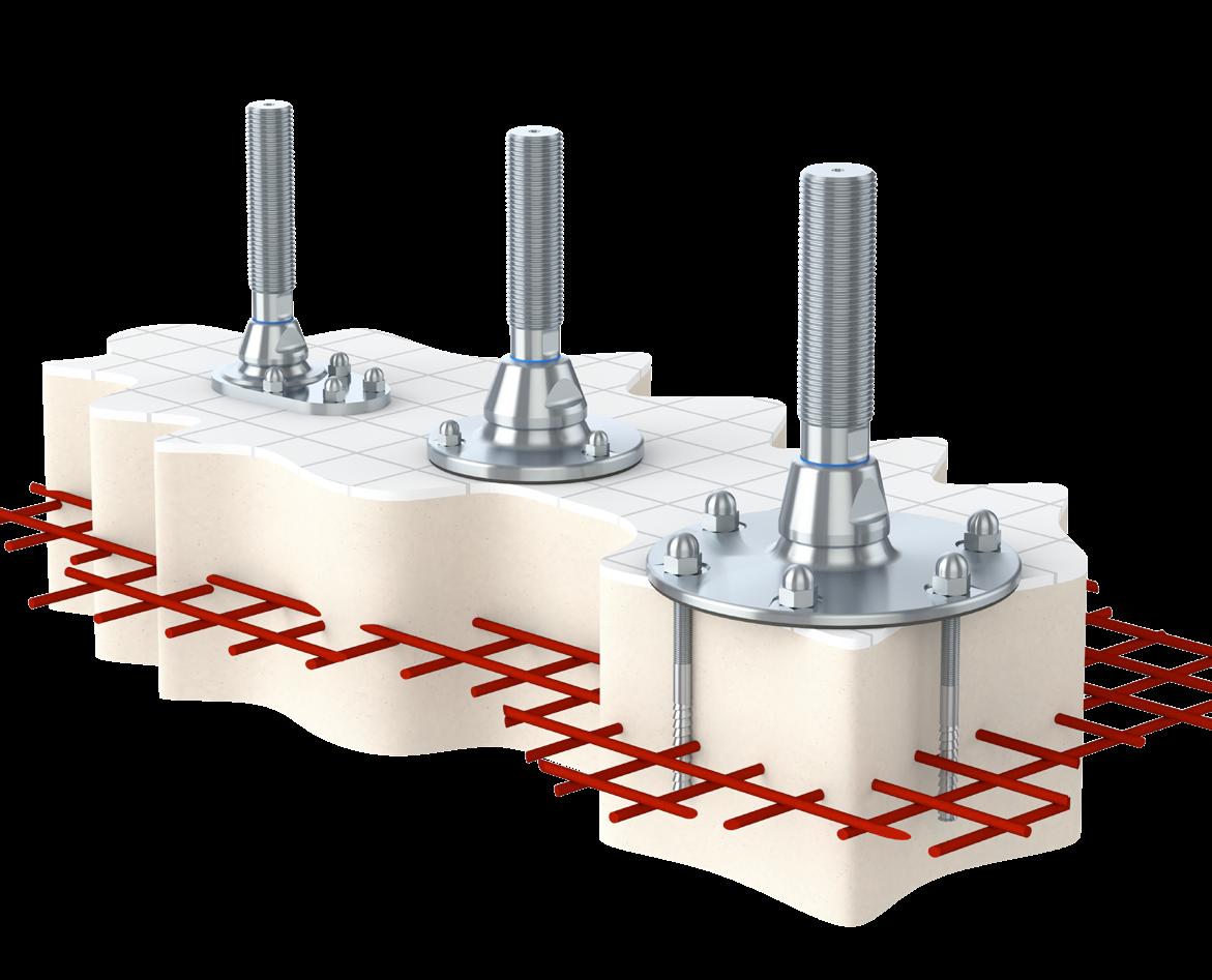

Our seismic levelling foot has been developed and tested using the Finite Element Method (FEA) and is compliant with the governmental regulations of California and New Zealand - (NZS 4219:2009).
Our seismic foot is capable of withstanding earthquakes due to its ability to withstand combinations of vertical and horizontal loads. The NGI seismic product confgurator combines earthquake risk data in the geographic area with data about your specifc equipment. The result of this detailed analysis will help you select the optimal solution in terms of safety and minimizing the risk of damage to your machinery and equipment caused by earthquakes.
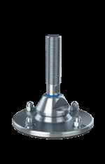
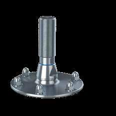
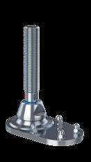
Special Features
• Simple and fast installation with height-adjustable compact design
• Movable set-up - no concrete molding required
• Total seismic stability through bolted fastening and patented locking mechanism
• Verifed through Finite Element Analysis (FEA) and calculated according to New Zealand seismic standard (NZS 4219)
• Seismic anchors chosen and approved by our experienced partner Hilti
• Optional certifed hygienic nuts from NGI
• Stainless steel AISI 304/A2, 1.4301. Optional AISI 316/A4, 1.4401


- Spindle sizes M30, M36, M42, M48 & M56 mm
- Available in two standard lengths per diameter size
- Circular arrangement of anchors for best seismic performance
- Sealed to the floor by rubber sealing
Special Features
Special Features
- Spindle sizes M56, M64, M80 & M90 mm
- Anchors decentered at one side of the spindle
- Available in two standard lengths per diameter size
- Not sealed to the floor
- Spindle sizes M56, M64, M72, M80 & M90 mm
- Available in two standard lengths per diameter size
- Circular arrangement of anchors for best seismic performance
Special Features
- Sealed to the floor by rubber sealing
- Spindle sizes M30, M36, M42, M48 & M56 mm
- Anchors decentered at one side of the spindle
- Available in two standard lengths per diameter size
- Not sealed to the floor HXJE
This declaration of conformity lists all the directives and standards that NGI adheres to. This ensures that products from NGI are always in compliance with currently valid requirements.
Installing seismic levelling feet requires several tools and accessories. NGI has teamed up with HILTI, the specialist for seismic anchoring, to ofer a complete seismic installtion kit for your seismic project. NGI is able to deliver all necessary accessories which ensures a quick and easy installation of the seismic levelling feet. It is important to use seismic approved accessories when fastening seismic feet. If not correctly installed it will meet neither 3A, USDA or EHEDG hygienic demands nor the seismic load specifcations.
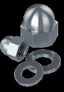
Special Features
- Stainless steel AISI 304/A2, 1.4301
- Standard dome-headed nuts (DIN 1587 A2)
- All dimensions available
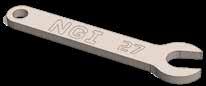
Special Features
XHJSE machine feet need three diferent wrenches for installation. NGI wrenches are laser cut and designed to ft NGI machine feet.
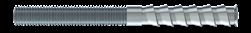
Special Features
- Stainless steel A4
- PROFIS software
- Base materials: concrete (cracked), concrete (uncracked), masonry (solid)
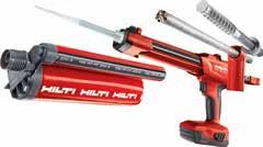
Special Features
Hilti’s seismic research includes detailed investigation of product performance under simulated seismic conditions and full-scale system testing.
The design and patent protected seismic HXJE (S) levelling foot is the optimal choice for all machinery, equipment, tanks and vessels located in areas subject to earthquakes and at the same time need to beneft from a long levelling range.
- Simple and fast installation with height-adjustable compact design
- Movable set-up - no concrete molding required
- Total seismic stability through bolted fastening and patented locking mechanism
- Verifed through Finite Element Analysis (FEA) and calculated according to New Zealand seismic standard (NZS 4219)
- Seismic anchors chosen and approved by our experienced partner Hilti
- Stainless steel AISI 304/A2, 1.4301. Optional AISI 316/A4, 1.4401
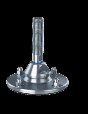
The design and patent protected seismic HXJE (L) levelling foot is the optimal choice for all machinery, equipment, tanks and vessels located in areas subject to earthquakes and at the same time need to beneft from a long levelling range.
- Simple and fast installation with height-adjustable compact design
- Adjustment through flat at the bottom of spindle
- Movable set-up - no concrete molding required
- Total seismic stability through bolted fastening and patented locking mechanism
- Verifed through Finite Element Analysis (FEA) and calculated according to New Zealand seismic standard (NZS 4219)
- Calculated according to New Zealand seismic standard NZS 4219
- Seismic anchors chosen and approved by our experienced partner Hilti
- Stainless steel AISI 304/A2, 1.4301. Optional AISI 316/A4, 1.4401
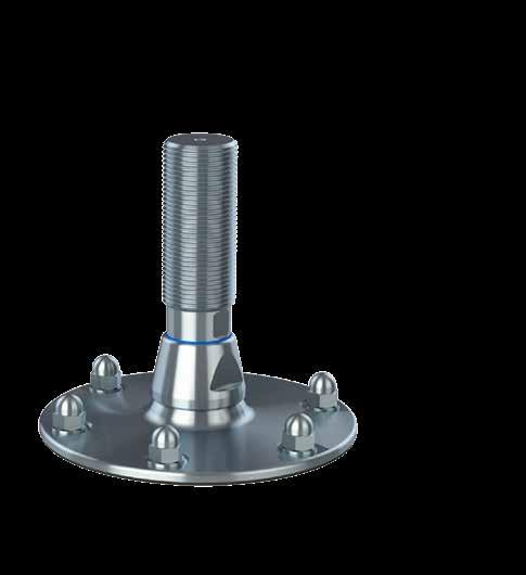
The design and patent protected seismic HXJCFE (S) levelling foot is the optimal choice for all machinery, equipment, tanks and vessels located in areas subject to earthquakes and at the same time need to beneft from a long levelling range.
- Anchors decentered at one side of the spindle
- Easier installation when machine restricts access to all sides of the footplate
- Lower seismic performance than round footplate
- Available in one size for small and one size for large
- Simple and fast installation with height-adjustable compact design
- Adjustment through flat at the bottom of spindle
- Movable set-up - no concrete molding required
- Total seismic stability through bolted fastening and patented locking mechanism
- Verifed through Finite Element Analysis (FEA) and calculated according to New Zealand seismic standard (NZS 4219)
- Calculated according to New Zealand seismic standard NZS 4219
- Seismic anchors chosen and approved by our experienced partner Hilti
- Stainless steel AISI 304/A2, 1.4301. Optional AISI 316/A4, 1.4401
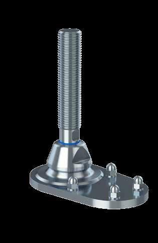
*L MIN is calculated without use of nut on spindle
The design and patent protected seismic HXJCFE (L) levelling foot is the optimal choice for all machinery, equipment, tanks and vessels located in areas subject to earthquakes and at the same time need to beneft from a long levelling range.
- Anchors decentered at one side of the spindle
- Easier installation when machine restricts access to all sides of the footplate
- Lower seismic performance than round footplate
- Available in one size for small and one size for large
- Simple and fast installation with height-adjustable compact design
- Adjustment through flat at the bottom of spindle
- Movable set-up - no concrete molding required
- Total seismic stability through bolted fastening and patented locking mechanism
- Verifed through Finite Element Analysis (FEA) and calculated according to New Zealand seismic standard (NZS 4219)
- Calculated according to New Zealand seismic standard NZS 4219
- Seismic anchors chosen and approved by our experienced partner Hilti
- Stainless steel AISI 304/A2, 1.4301. Optional AISI 316/A4, 1.4401
NGI A/S fundamentally adheres to all applicable directives and standards. All information is based on the current state of knowledge and is subject to change. We attentive follow the revisions/amendments to these directives and will design our products accordingly. This ensures that products from NGI A/S are always in compliance with currently valid requirements.
Our type of products is not covered by the scope of application of the EC directive on machinery. For this reason, they cannot be furnished with the CE marking in accordance with the EC directive on machinery.
NGI A/S, Virkelyst 3-7, 9400 Nørresundby, hereby declare that the listed materials applied for the products comply with the demands for materials used within the food and pharmaceutical industry.
Furthermore, we declare that the listed materials applied for the products comply with the demands for materials used within the food and pharmaceutical industries.

Metallic surfaces are constructed from Stainless steel, AISI 304/A2 or by request Stainless steel, AISI 316/A4 and are corrosion resistant under the specifed conditions of use including those of cleaning.
The elastomeric components are constructed from FDA approved NBR and silicone material. All materials used are considered non-toxic and are non-absorbent.
All exposed metallic surfaces are fnished to maximum surface roughness values of 1.6 pm Ra. All elastomeric components and sealing washers are left as molded with no hand trimming and all surfaces are considered smooth enough to ensure that cleaning is easy.
There are no exposed dissimilar metal-to-metal contact areas in the construction where galvanic corrosion could occur.
Sealing designs permit access for easy cleaning with no inaccessible pockets or crevices.
There are no risk of exposed threads and no unsealed metal-to-metal joints in the fnished construction.
All exposed surfaces have a smooth fnish such that soil may be cleaned from the surface using manual cleaning techniques and be free of pits, folds, cracks, crevices, and other imperfections in the fnal fabricated form.
Drainability and Installation
The units are designed to be self-draining and contain no horizontal ledges.
Comprehensive instructions are provided containing detailed information to ensure compliance with the 3-A and EHEDG design criteria, when the product is certifed.
The 3-A Sanitary Standard 88-00 requires that when machine leveling feet or supports are properly mounted on the equipment, they shall provide a minimum clearance between the lowest part of the equipment and the floor of not less than 4.0 in. (102 mm) if the equipment outlines an area in which no point is more than 12.5 in. (318 mm) from its nearest edge. If the equipment outlines an area in which any point is more than 12.5 in. (318mm) from its nearest edge the clearance shall be at least 6 in. (152mm).
The EHEDG guideline recommends a minimum clearance between the equipment and the floor or wall of 300mm for easy cleaning and inspection.
When fasteners are required, only domed head screws and dome headed nuts must be used. The exposed interfaces shall be sealed with sealing washers and there must be no threads exposed in the installed confguration of the machine feet.
Minimized cleaning time Certified hygienic
Minimized water usage
Foot bases can be sealed to the floor if required. The instructions make recommendations not to span over floor imperfections or grout lines without the addition of proper sealing compounds.
Maximum torque values are specifed as appropriate on fastening arrangements to avoid over-compression of sealing washers and gaskets.
Maintenance instructions are clearly defined and prohibit the use of non-genuine replacement parts.
Cleaning instructions describe typical cleaning procedures with recommended maximum temperatures/pressures and stipulate the use of non-abrasive cleaning aids.
The design does not contain dead spaces and avoid accumulation of soil, microorganism’s insects and other vermin in areas which cannot be easily cleaned.
Sealing and thread locking compounds used in the construction are non-toxic in the cured state.
No lubricants, insulation material or signal transfer liquids are used in the construction.
Standards and directives
EN 1672-2:2005 Food machinery / General design principles/Part 2: Hygiene requirements.
EN ISO 14 159 2004 Safety of machinery – Hygiene requirements for the design of machinery.
Document 13 EHEDG guideline on the hygienic design of apparatus for open processes.
Similar NGI designs meets the criteria for Hygienic Equipment Class I for components situated in the non-food area and are accessible for easy cleaning without dismantling.
The weighing levelling feet design is according to 3-A Sanitary Standard for Machine Leveling Feet and Supports.
Certifed according to USDA Guidelines “Dairy Equipment and NSF ANSI 3-A 14159-12014 for the sanitary design and fabrication.
New Zealand seismic standard NZS 4219.

EU regulations
852/2004 on the hygiene of foodstufs.
853/2004 specifc hygiene rules for food of animal origin.
854/2004 specifc rules for the organization of official controls on products of animal origin intended for human consumption.
1935/2004 on materials and articles intended to come into contact with food
The declaration of materials concerns the following Applications
Application: STEEL COMPONENT
Material type: Stainless steel, AISI 304/A2 (X5CrNi18-10), Euro norm 1.4301. By request: Stainless steel, AISI 316/A4 (X 5 CrNiMo 17 12 2), Euronorm 1.4401
Compliance: EN 10204 Type 2.2. NGI A/S states that the product is in compliance with the order with indication of results of nonspecifc inspection. NGI A/S has got EN 10204 type 3.1 inspection certifcates on all material used in the products but not specifed for each foot.
In the directive 94/9/EC, Equipment for potentially explosive atmospheres, also known as the ATEX directive, equipment without its own potential source of ignition are not covered, nor shall be marked according to the directive. However, NGI levelling feet are suitable for use in all ATEX zones.
Application: Foot sealing
Material type: NBR by request EPDM
Electrically: Non-conductive
Color: Black
Hardness: Shore A 80 ± 5
Range of temperature: Min -20°C to Max +110°C
Load: Low load capacity
Compliance:
REACH: In accordance with regulation EC 1907/2006. Do not contain any substances above 0.1% (w/w) from: The Candidate List of Substances of Very High Concern (16.01.2020). Annex XVII (19-11-2019)
RoHS 2 & RoHS 3 In accordance with the directive 2011/65/EC and 2015/863/EC OF EUROPEAN PARLIAMENT AND OF THE COUNCIL.
ADI free: Does not contain any substances originating from humans or animals.
Bisphenols: Does not contain Bisphenols as described in 1895/2005/EEC. Nor BPA, BADGA, BFDGE or NOGE.
ODS: Does not contain ozone depleting substances. In accordance with the Regulation EC 1005/2009 OF EUROPEAN PARLIAMENT AND OF THE COUNCIL OF 16 SEPTEMBER 2009 and Regulation EC 2037/2000 OF EUROPEAN PARLIAMENT AND OF THE COUNCIL OF 29 JUNE 2000.
Conflict
Materials: In accordance with US Law: ”Dodd Frank Wall Street Reform & Consumer Protection Act”, sec. 1502, of 21.07.2010.
GMP: Good manufacturing process in accordance with 2023/2006 EC.
Hazardous
materials: Does not contain any hazardous substances as described in the Hong Kong International Convention for the Safe and Environmental. Sound Recycling of ships, 2009.
Phthalates: Does not contain phthalates.
FDA: Guideline 21 CFR 177.2600
Application: Sealing ring
Material type: Silicon rubber
Electrically: Non-conductive
Chemical resistance: High to commonly applied cleaning agents
Hardness: Shore A 60 ± 5
Color: RAL 5010 (blue)
Range of temperature: Min -60°C to Max +200°C
Storage: According to ISO 2230
Compliance:
FDA: Guideline 21 CFR 177.2600
RoHS 2: In accordance with the Directive 2011/65/EC OF EUROPEAN PARLIAMENT AND OF THE COUNCIL.
GMP: Good manufacturing process in accordance with 2023/2006 EC.
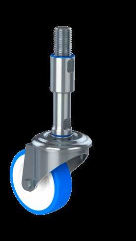
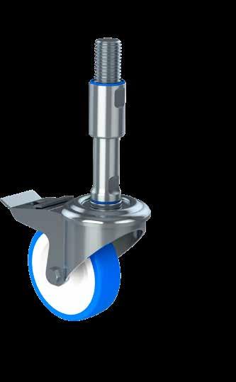
The classic hygienic-oriented design for machinery and equipment for use in diverse wet production environments
They offer value for money and are available in numerous varieties and functions
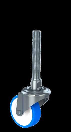

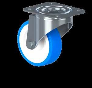
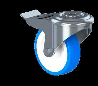
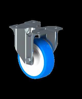
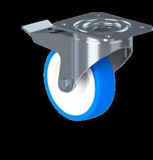
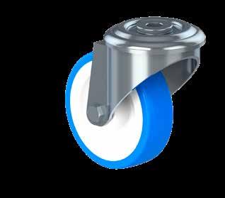
NGI is the only manufacturer in the world of castors with hygienic levelling spindles. The product group consists of three hygienic-oriented types of castors: A castor with a plate ftting, a castor with levelling spindles and a single bolt hole Ø13.
The castor type with hygienic levelling spindles makes it possible to level your machinery and equipment while maintaining an acceptable hygienic design. All types of castors are an acceptable choice for machinery and equipment in diverse sanitary production environments.
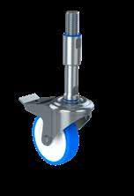
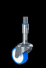
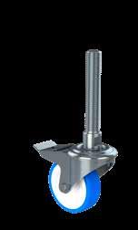
Special Features
- Hygienic levelling swivel castor
- Height variation 184 - 367 mm
- Brake and swivel on wheel
- Double ball bearing swivel head
- Weight load up to 1.500 N
Special Features
- Hygienic levelling swivel castor
- Height variation 184 - 367 mm
- Double ball bearing swivel head
- Dynamic weight load up to 1.500 N
Special Features
- Swivel levelling castor
- Brake on swivel and wheel
- Double ball bearing swivel head
- Weight load up to 1.500 N
• Fork housing made of stainless steel AISI 304/A2, 1.4301.
• Wheel axle with nut
• White castor rim made of polyamide
• Blue tread made from polyurethane
• Stainless steel roller bearings
• Wheel dimensions Ø80, Ø100 and Ø125
• Load capacity tested according to EN 12532
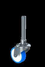
Special Features
- Swivel levelling castor
- Double ball bearing swivel head
- Weight load up to 1.500 N
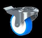
Special Features
- Swivel castor with single bolt hole Ø13
- Brake on swivel and wheel
- Double ball bearing swivel head
- Weight load up to 1.500 N
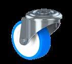
Special Features
- Swivel castor with single bolt hole Ø13
- Double ball bearing swivel head
- Weight load up to 1.500 N
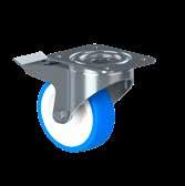
Special Features
- Swivel castor with plate ftting
-Brake on swivel and wheel
- Double ball bearing swivel head
- Weight load up to 4.000 N
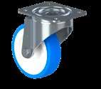
Special Features
- Swivel castor with plate ftting
- Double ball bearing swivel head
- Weight load up to 3.500 N
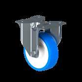

Special Features
- Swivel castor with plate ftting
- Rigid swivel
- Weight load up to 4.000 N
The SCRB-XH hygienic levelling swivel castor is the optimal choice for machinery and equipment in diverse sanitary production environments.
The SCRB-XH is equipped with a brake on swivel and wheel.
The thread on the spindle is covered with a hygienic sleeve, which cannot be overadjusted and secures safety against exposed thread. The sleeve also functions as counter nut.
Spindle parts are 100% hygienically sealed with blue sealings detectable by scanning systems.
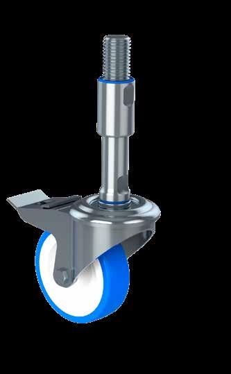
The design and patent protected SCR-XH hygienic levelling swivel castor is the optimal choice for machinery and equipment in diverse sanitary production environments.
Spindle parts are 100% hygienically sealed with blue sealings detectable by scanning systems.
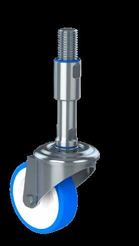
The SCRB-HX levelling swivel castor is the optimal choice for machinery and equipment in diverse production environments.
The SCRB-HX is equipped with a horisontal and vertical brake, which totally locks the position of the castor.
Spindle parts are 100% hygienically sealed with blue sealings detectable by scanning systems.
SPINDLE
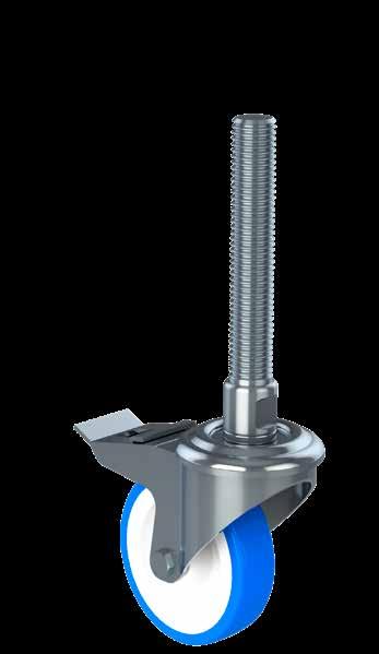
The SCR-HX hygienic levelling swivel castor is the optimal choice for machinery and equipment in diverse production environments.
Spindle parts are 100% hygienically sealed with blue sealings detectable by scanning systems.
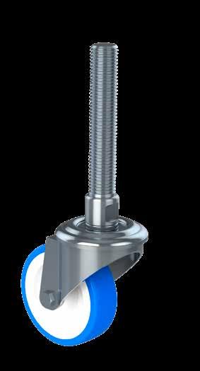
HEIGHT A [mm]
The SCRB swivel castor with round mounting is the optimal choice for machinery and equipment in diverse production environments.
The SCRB is equipped with a brake on swivel and wheel.
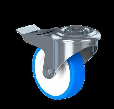
The SCR swivel castor with round mounting is the optimal choice for machinery and equipment in diverse production environments.
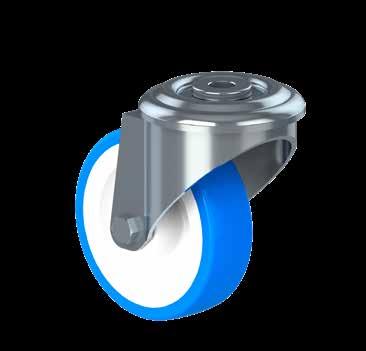
The SCSB hygienic swivel castor with a fxing plate is the optimal choice for machinery and equipment in diverse sanitary production environments.
The SCSB is equipped with a brake on swivel and wheel.
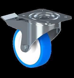
The SCS hygienic swivel castor with a fxing plate is the optimal choice for machinery and equipment in diverse sanitary production environments.
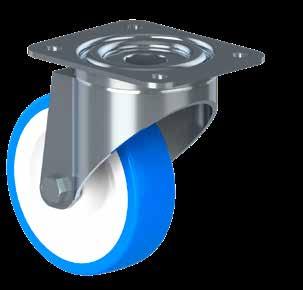
The CS hygienic fxed castor is the optimal choice for machinery and equipment in diverse sanitary production environments.
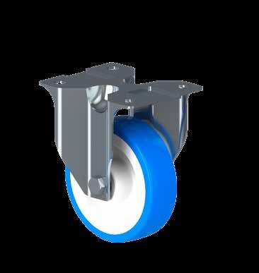
NGI fundamentally adheres to all applicable directives and standards. All information is based on the current state of knowledge and is subject to change. We attentively follow the revisions and amendments to these directives and will design our products accordingly. This ensures that products from NGI are always in compliance with currently valid requirements.
Our product category is not covered by the scope of application of the EC directive for machinery. For this reason, they cannot be furnished with the CE marking in accordance with the EC directive for machinery.
Furthermore, we declare that the listed materials applied in our products comply with the demands for materials used within the food and pharmaceutical industries.
SEAL
SEAL
SEAL
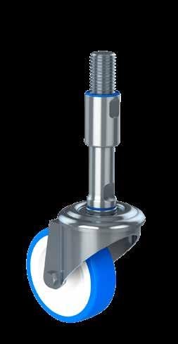
STAINLESS STEEL
STAINLESS STEEL
STAINLESS STEEL
STAINLESS STEEL
The declaration of materials concerns the following Applications
Application: Steel spindle and sleeve
Material type: Stainless steel, AISI 304/A2 (X5CrNi18-10), Euronorm 1.4301. By request: Stainless steel, AISI 316/A4 (X 5 CrNiMo 17 12 2), Euronorm 1.4401
Compliance: EN 10204 Type 2.2. NGI A/S states that the product is in compliance with the order
with indication of results of nonspecifc inspection.
NGI has got EN 10204 type 3.1 inspection certifcates on all material used in the products but not specifed for each foot.
In the directive 94/9/EC, Equipment for potentially explosive atmospheres, also
known as the ATEX directive, equipment without its own potential source of ignition are not covered, nor shall be marked according to the directive.
However,
NGI levelling castors are suitable for use in all ATEX zones.
Application: Castor Description:
Material type: Stainless steel AISI 304/A2, 1.4301: Fork housing, wheel axle with nut and roller bearings
White castor rim made of polyamide Blue tread made from polyurethane
Dimensions: Wheel dimensions Ø80, Ø100, Ø125, Ø160 and Ø200
Compliance: Load capacity tested according to EN 12532
Application: Sealing ring between steel components for NGI’s castors.
Material type: Silicon rubber
Electrically: Non-conductive
Chemical resistance: High to commonly applied cleaning agents
Color: RAL 5010 (blue)
Hardness: Shore A 60 ± 5
Range of temperature: Min -60°C to Max +200 °C
Storage: According to ISO 2230
Compliance:
FDA: Guideline 21 CFR 177.2600
RoHS 2: In accordance with the Directive 2011/65/EC OF EUROPEAN PARLIAMENT AND OF THE COUNCIL.
GMP: Good manufacturing process in accordance with 2023/2006 EC.
The only hygienic tank support bolt in the world with sealing between welding connector and spindle
Sealed movable parts and no exposed thread reduces cleaning and increases sanitary safety
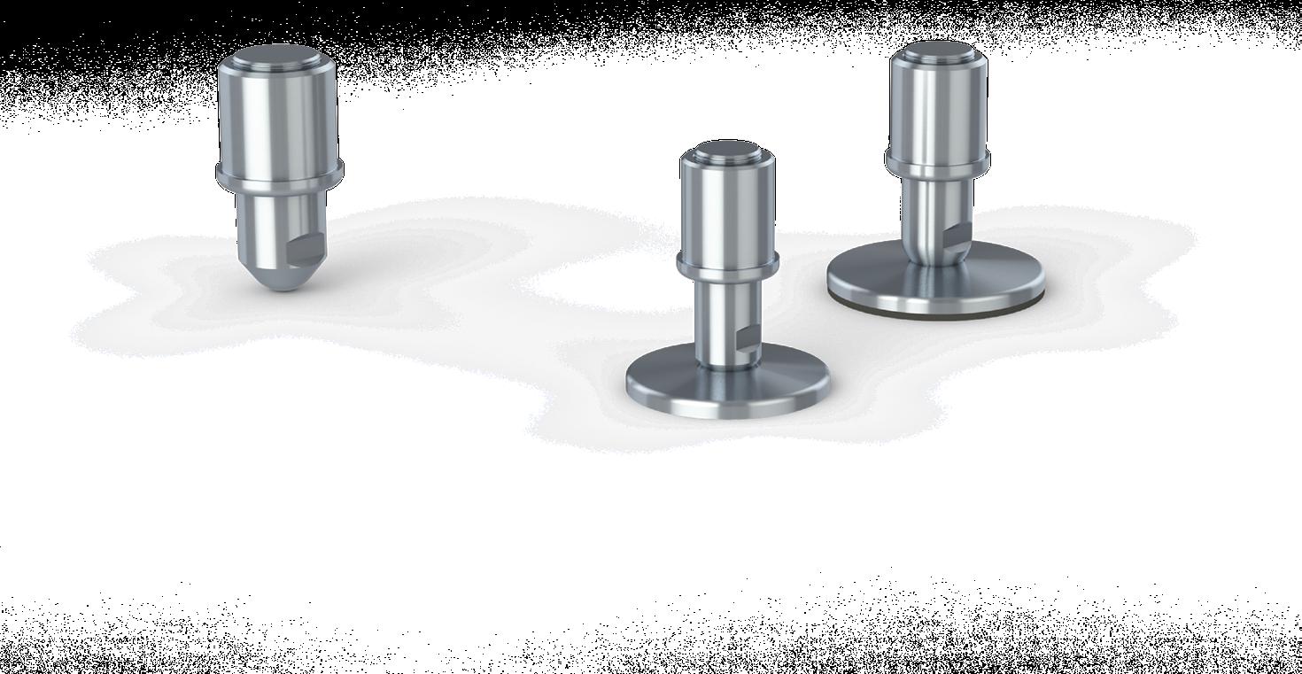
The product group of hygienic-oriented tank support bolts is the optimal choice for extremely heavy machinery, equipment, tanks and vessels in diverse production environments.
Limited cleaning efort is obtained by sealing the welding connector with a fxed blue sealing ring that is detectable by scanning systems. Choosing NGI’s tank support bolts will secure your heavy machinery with a hygienic design.
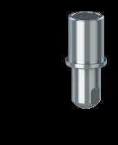
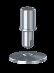
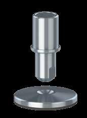
Special Features
- Height variation 32 mm – 85 mm
- Weight load up to 493.600 N
- The support bolt absorbs slants up to 20°
• Designed for high load capacity
• Solid hygienic-oriented design with no exposed thread and limited cleaning efort
• Sealed welding connector with BSPP pipe thread
• Customized welding connectors available
• Optional counter nut available
• Optional anti-vibration, anti-slip rubber underneath the footplate
• Stainless steel AISI 304/A2, 1.4301. Optional AISI 316/A4, 1.4401
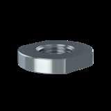
- Counterlocks the spindle against the top of the welding connector
Special Features
- Height variation 38 mm – 94 mm
- Weight load up to 200.000 N
- The footplate and support bolt are two separate parts
- Diametrically centered depression in the footplate
- The support bolt absorbs slants up to 20°
Special Features
- Height variation 43 mm – 98 mm
- Weight load up to 30.000 N
- The footplate and support bolt are two separate parts
- Diametrically centered depression in the footplate
- The support bolt absorbs slants up to 20°
- Anti-vibration, anti-slip rubber underneath the footplate
This declaration of conformity lists all the directives and standards that NGI adheres to. This ensures that products from NGI are always in compliance with currently valid requirements.
The SBX support bolt is the optimal choice for extremely heavy machinery, equipment, tanks and vessels in diverse production environments.
Limited cleaning efort is obtained by sealing the welding connector with a fxed blue sealing ring that is detectable by scanning systems. The SBX support bolt secures your heavy machinery with a hygienic design.
Standard sizes are listed on the datasheet. Optional customized designs are available upon request.
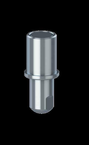
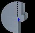
The KTSBX support bolt with footplate is the optimal choice for extremely heavy machinery, equipment, tanks and vessels in diverse production environments where distribution of the weight load is required.
The KTSBX consists of a separated footplate, support bolt and welding connector. The support bolt is held in place by the diametrically centered depression in the footplate.
Limited cleaning efort is obtained by sealing the welding connector with a fxed blue sealing ring that is detectable by scanning systems. The KTSBX support bolt secures your heavy machinery with a hygienic design.
Standard sizes are listed on the datasheet. Optional customized designs are available upon request.
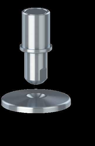
The KTSBX AS support bolt with anti-slip footplate is the optimal choice for machinery, equipment, tanks and vessels in diverse production environments where distribution of the weight load is required.
The KTSBX AS consists of a separated footplate, support bolt and welding connector. The support bolt is held in place by the diametrically centered depression on the footplate.
Additionally, the foot is sealed to the floor by the anti-slip rubber, which blocks out bacteria underneath the footplate.
Limited cleaning efort is obtained by sealing the welding connector with a fxed blue sealing ring that is detectable by scanning systems. The KTSBX AS support bolt secures your heavy machinery with a hygienic design.
Standard sizes are listed on the datasheet. Optional customized designs are available upon request.
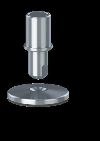
This counter nut is used from above and counterlocks the spindle against the top of the welding connector.
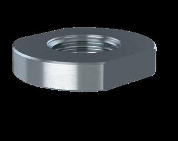
NGI fundamentally adheres to all applicable directives and standards. All information is based on the current state of knowledge and is subject to change. We attentively follow the revisions and amendments to these directives and will design our products accordingly. This ensures that products from NGI are always in compliance with currently valid requirements.
Our product category is not covered by the scope of application of the EC directive for machinery. For this reason, they cannot be furnished with the CE marking in accordance with the EC directive for machinery.
Furthermore, we declare that the listed materials applied in our products comply with the demands for materials used within the food and pharmaceutical industries.
Application: Steel spindle and sleeve
Material type: Stainless steel, AISI 304/A2 (X5CrNi18-10), Euronorm 1.4301. By request: Stainless steel, AISI 316/A4 (X 5 CrNiMo 17 12 2), Euronorm 1.4401
Compliance: EN 10204 Type 2.2. NGI A/S states that the product is in compliance with the order with indication of results of nonspecifc inspection.
NGI has got EN 10204 type 3.1 inspection CERTIFIEDs on all material used in the products but not specifed for each foot.
In the directive 94/9/EC, Equipment for potentially explosive atmospheres, also known as the ATEX directive, equipment without its own potential source of ignition are not covered, nor shall be marked according to the directive. However, NGI levelling feet are suitable for use in all ATEX zones.
Application: Anti slip
Material type: NBR By request EPDM
Electrically: Non-conductive
Chemical resistance: High to commonly applied cleaning agents
Color: Black
Hardness: Shore A 80 ± 5
Range of temperature: Min -20 °C to Max 110 °C
Load: Low load capacity
Application: Sealing ring between steel components for NGI’s machine feet.
Material type: Silicon rubber
Electrically: Non-conductive
Chemical resistance: High to commonly applied cleaning agents
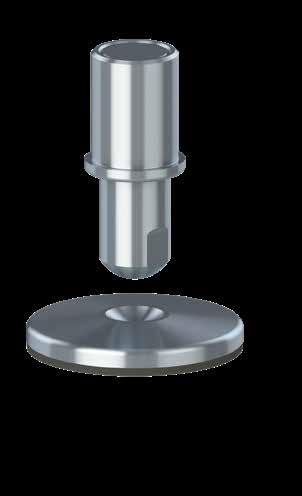
Color: RAL 5010 (blue)
Hardness: Shore A 60 ± 5
Range of temperature: Min -60°C to Max +200 °C
Storage: According to ISO 2230
Compliance: FDA: Guideline 21 CFR 177.2600
RoHS 2: In accordance with the Directive 2011/65/EC OF EUROPEAN PARLIAMENT AND OF THE COUNCIL.
GMP: Good manufacturing process in accordance with 2023/2006 EC.
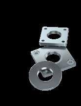
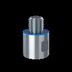
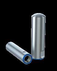
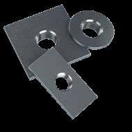
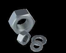
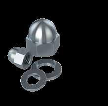
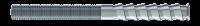

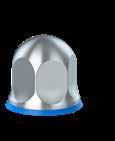
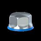
NGI is able to deliver all necessary accessories which ensures a quick and easy installation of hygienic components.
In addition to supplying standardized accessories we are also able to supply customized accessories.
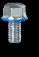
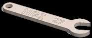
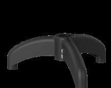
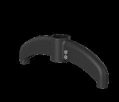
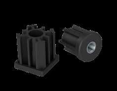
NGI is able to deliver all necessary accessories, which ensures a quick and easy installation of the levelling foot, bearing house and castor.
In addition to supplying standardized accessories we are also able to supply customized accessories.
- Certifed in accordance with 3-A (RPSCQC)
- Certifed in accordance with EHEDG hygienic standard TYPE EL
- CLASS I AUX
- Minimizes cleaning time and water consumption
- Surfaces with a maximal roughness of 0,8 µm RA
- Available in sizes M6-M24
- Are delivered with all certifed hygienic machine feet with floor fxing
- Certifed in accordance with 3-A (RPSCQC)
- Certifed in accordance with EHEDG hygienic standard TYPE EL
- CLASS AUX
- Minimizes cleaning time and water consumption
- Surfaces with a maximal roughness of 0,8 µm RA
- Available in sizes M5-M24
- Certifed in accordance with 3-A (RPSCQC)
- Certifed in accordance with EHEDG hygienic standard TYPE EL
- CLASS I AUX
- Minimizes cleaning time and water consumption
- Surfaces with a maximal roughness of 0,8 µm RA
- Available in sizes M5-M24
- Top cover with blue sealing detectable by scanning systems
- Ensures hygienic covering of the exposed top thread
- Minimum cleaning efort due to the self-draining design
- Available in standardized and customized dimensions
- Add-on for the XHFV & ZHFVJ system
- Adaptor converts the size and type of the thread and extends the sleeve. It has blue sealings detectable by scanning systems.
- Flanges are squared or round and installed by bolting or welding. They are available in a large variety of sizes.
- Stainless steel AISI 304/A2, 1.4301
- Standard nuts (DIN 934)
- Standard counter nuts (DIN 439)
- Standard flat washers (DIN 125)
- Standard fender washers (DIN 9010)
- All dimensions available
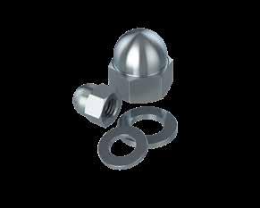
- Stainless steel AISI 304/A2, 1.4301
- Standard dome-headed nuts (DIN 1587 A2)
- All dimensions available
NGI is able to deliver all necessary accessories, which ensures a quick and easy installation of the levelling foot, bearing house and castor. In addition to supplying standardized accessories we are also able to supply customized accessories.
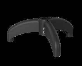
- Conveyor support tripod
- Supports fve tube diameters from Ø38.1 to Ø60.3
- Select three optional M16 levelling feet
- NGI recommends levelling foot M050-16-070
- Stainless steel AISI 304/A2, 1.4301
- Squared welding plates
- Round welding plates
- All dimensions available
- Squared plastic bushings
- Round plastic bushings
- Many dimensions available
XHJSE machine feet need three diferent wrenches for installation. NGI wrenches are laser cut and designed to ft NGI machine feet.
Hilti’s seismic research includes detailed investigation of product performance under simulated seismic conditions and full-scale system testing.
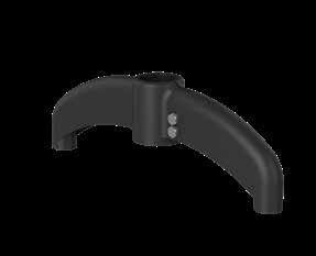
- Conveyor support bipod
- Supports fve tube diameters from Ø38.1 to Ø60.3
- Select two optional M16 levelling feet
- NGI recommends levelling foot M050-16-070
- Stainless steel A4
- PROFIS software
- Base materials: concrete (cracked), concrete (uncracked), masonry (solid)
Certifed hygienic nuts with blue NBR rubber seals is the right choice of nuts to be used on all machinery in all certifed hygienic wash-down environments. The NBR rubber seal blocks out water and bacteria and also prevents a non-hygienic metal-to-metal assembly. Round-headed and self-draining surfaces with a maximal roughness of 0.8 µm Ra.
The design of the nuts does not deviate from the sizes of current standard nuts. Therefore, wrench sizes, thread heights etc. all remains the same making it very easy to upgrade and replace standard nuts. NGI’s certifed hygienic nuts are used for floor-mounting of certifed hygienic levelling feet in order to ensure compliance with current legislation towards hygienic design.
The NDXH is used when the length of exposed bolt thread can vary.
- Certifed in accordance with 3-A (RPSCQC)
- Certifed in accordance with EHEDG hygienic standard TYPE EL - CLASS I AUX
- Minimizes cleaning time and water consumption
- Surfaces with a maximal roughness of 0,8 µm Ra
- Available in sizes M6-M24
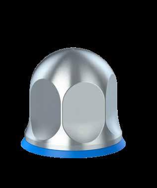
Certified hygienic
Minimized cleaning time
Minimized water usage
CERTIFIED HYGIENIC NUTS
T
Certifed hygienic nuts with blue NBR rubber seals is the right choice of nuts to be used on all machinery in all certifed hygienic wash-down environments. The NBR rubber seal blocks out water and bacteria and also prevents a non-hygienic metal-to-metal assembly. Round-headed and self-draining surfaces with a maximal roughness of 0.8 µm Ra.
The design of the nuts does not deviate from the sizes of current standard nuts. Therefore, wrench sizes, thread heights etc. all remains the same making it very easy to upgrade and replace standard nuts. NGI’s certifed hygienic nuts are used for floor-mounting of certifed hygienic levelling feet in order to ensure compliance with current legislation towards hygienic design.
The NLXH is used when the length of exposed bolt thread is adapted to the nut’s B2 measurement.
- Certifed in accordance with 3-A (RPSCQC)
- Certifed in accordance with EHEDG hygienic standard
TYPE EL - CLASS I AUX
- Minimizes cleaning time and water consumption
- Surfaces with a maximal roughness of 0,8 µm Ra
- Available in sizes M5-M24
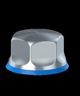
Certified hygienic
Minimized cleaning time
Minimized water usage
Minimized cleaning time Certified hygienic
Minimized water usage
NGI is now able to ofer certifed hygienic bolts with blue NBR rubber seals. The NBR rubber seal blocks out water and bacteria and also prevents a non-hygienic metal-to-metal assembly.
The bolts have self-draining surfaces with a maximal roughness of 0.8 µm Ra. The design of the bolts does not deviate from the sizes of current standard bolts. Therefore, wrench sizes, thread heights etc. all remains the same making it very easy to upgrade and replace standard bolts. This is the right choice of bolts to be used on all machinery in all certifed hygienic wash-down environments.
- Certifed in accordance with 3-A (RPSCQC)
- Certifed in accordance with EHEDG hygienic standard TYPE EL - CLASS I AUX
- Minimizes cleaning time and water consumption
- Surfaces with a maximal roughness of 0,8 µm Ra
- Available in sizes M5-M24 CERTIFIED HYGIENIC BOLTS
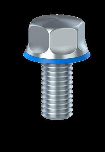
The top cover is designed to be used in situations where the top of the thread is exposed, which compromises the hygienic performance and certifcation of the levelling foot.
By applying the top cover the exposed thread is hygienically covered. The top cover can also function as counter nut.
The top cover is supplied with a blue sealing detectable by scanning systems and minimum cleaning efort is obtained due to the self-draining design.
Available in standardized and customized dimensions.
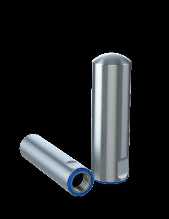
Certified hygienic
Minimized cleaning time
Minimized water usage
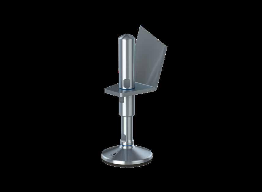
The flange is used when mounting the XHFV levelling feet into the machine or equipment.
Machinery and equipment requires diferent mounting and therefore the flange is available in several variations.
- Squared - Round - Large variety of sizes - Install by bolting or welding
Customized sizes and shapes can be supplied by request.
Certified hygienic
Minimized cleaning time
Minimized water usage
ROUND - WELDING
SQUARED - BOLTING
SQUARED - BOLTING
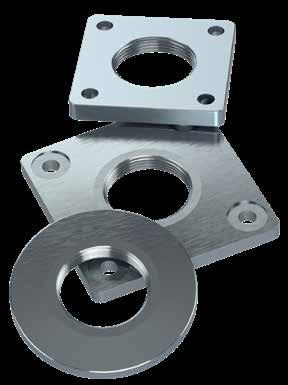
SQUARED - WELDING
Minimized cleaning time Certified hygienic
Minimized water usage
The thread adaptor is an add-on for the XHFV & ZHFVJ system. It converts the size and type of the thread and extends the sleeve. Furthermore, it is equipped with blue sealings detectable by scanning systems. Available in customized sizes.
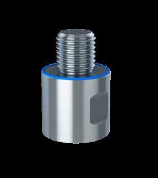
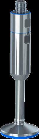
- Stainless steel AISI 304/A2, 1.4301 - Standard nuts (DIN 934) - Standard counter nuts (DIN 439) - Standard flat washers (DIN 125) - Standard fender washers (DIN 9010) - All dimensions available
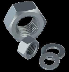
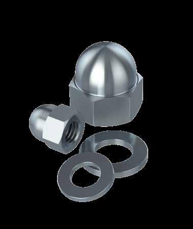
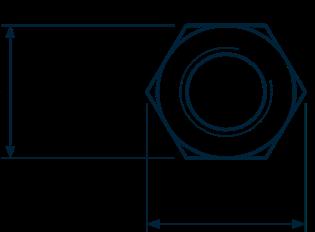
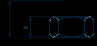

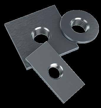
- Squared plastic bushings - Round plastic bushings - Many dimensions available
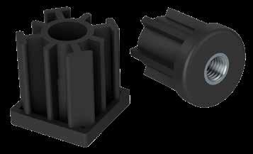
The bipod plastic base accepts fve diferent standard tube sizes from Ø38.1 to Ø60.3 The tube leg is fxed with two bolts with spacers to ensure correct tightening. Select two optional M16 levelling feet. NGI recommends levelling foot M050-16-070.
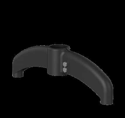
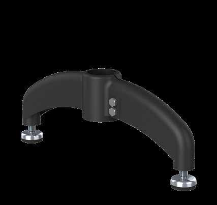
The tripod plastic base accepts fve diferent standard tube sizes from Ø38.1 to Ø60.3
The tube leg is fxed with two bolts with spacers to ensure correct tightening.
Select three optional M16 levelling feet.
NGI recommends levelling foot M050-16-070.
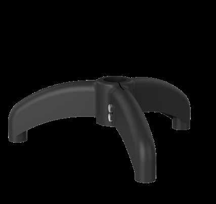
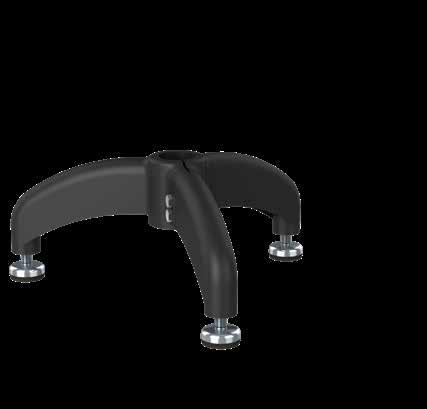
XHJSE machine feet need three diferent wrenches for installation.
NGI wrenches are laser cut and designed to ft NGI machine feet.
Please check the selection guide to see which sizes are needed for your respective model.
• W1: Spindle
• W2: Sleeve
• W3: Counter nut

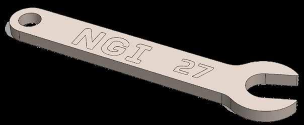
Hilti’s seismic research includes detailed investigation of product performance under simulated seismic conditions and full scale system testing.
This multilevel approach helps to capture the complexity of fastening systems behavior under seismic conditions. Earthquakes can afect a wide range of construction products that Hilti supplies anchors for and NGI are confdent that they are the best on the market today. Hilti is pioneering research to extensively test systems for earthquake performance in order to support their customers with recommendations for design applications.
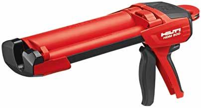
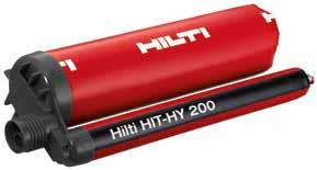
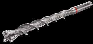
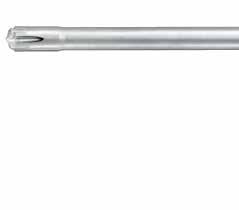
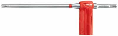


TE-CX 12/22 12X220 150 M10 TE-CX 14/22 14X220 150 M12 TE-CX 18/32 18X320 250 M16
TE-CX 22/48 22X480 410 M20
TE-CX 28/48 28X480 410 M24

TE-CD 12/33 12X330
14/37 14X370
TE-CD 18/37 18X370
HXJCFE150(S)/ XHJCFE150(S) M12x155 HIT-Z-R 4
HXJE150(S)/ XHJSE150(S) M10x160 HIT-Z-R 3
HXJE200(S)/ XHJSE200(S) M12x155 HIT-Z-R 4
HXJE250(S)/ XHJSE250(S) M16x250 HIT-Z-R 4
HXJCFE300(L)/ XHJCFE300(L) M16x240 HIT-Z-R
XHJSE250(L)
XHJSE300(L)
HXJE350(L)/ XHJSE350(L) M20x250
High-performance anchor rod for injectable hybrid/epoxy anchors (A4 stainless steel).
• Material, corrosion: Stainless steel, A4
• Base materials: Concrete (cracked), Concrete (uncracked), Masonry (solid)
• PROFIS software: Yes

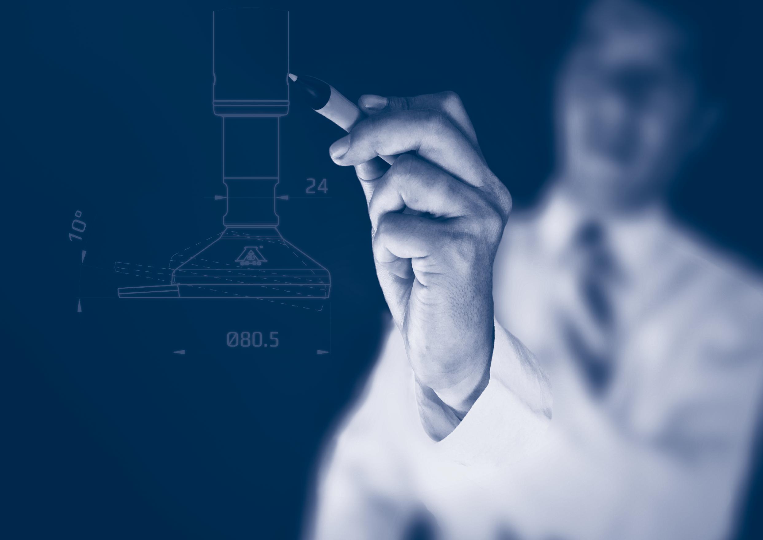
Application:
Material type:
Compliance:
Spindle, sleeve and foot cover
Stainless steel, SISI 304/A2 (X5CrNi18-10), Euronorm 1.4301. By request: Stainless steel, AISI 316/A4 (X 5 CrNiMo 17 12 2). Euronorm 1.4401.
EN 10204 Type 2.2. NGI a/s states that the product is in cimpliance with the order with indication of results of non-specifc inspection. NGI has EN 10204 type 3.1 inspection CERTIFIEDs on all material used in the products but not specifed for each foot.
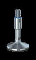
Application:
Material type:
Hardness:
Color:
Range of temperature:
Storage:
Compliance:
Sealing ring between steel components
Silicon rubber
60 Shore A RAL 5010 (blue)
Min. -60 º C to max. +200 º C
According to ISO 2230
FDA: Guideline 21 CFR 177.2600
RoHS 2: In accordance with the Directive 2011/65/ EC OF EUROPEAN PARLIAMENT AND OF THE COUNCIL
GMP: Good Manufacturing Process in accordance with 2023/2006 EC
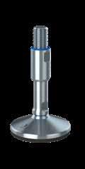
Application:
Material type:
Color:
Hardness:
Range of temperatures: Complicanc with:
Sealing
NBR
Black
72 +/- 3 Shore A DIN 53 505
Min. -35 º C to max. +110 C
REACH, RoHS & RoHS 2, ADI free, EC 100S/2009, EC 2037/2000, 2023/2006 EC, No Phthalates, FDA approved.
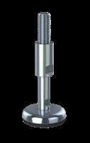
Application:
Material type:
Color:
Hardness:
Range of temperatures: Complicanc with:
Vulcanized rubber
NBR
Black
72 +/- 3 Shore A DIN 53 505
Min. -35 º C to max. +110 º C
REACH, RoHS & RoHS 2, ADI free, EC 100S/2009, EC 2037/2000, 2023/2006 EC, No Phthalates, FDA approved.
Application:
Material type:
Electrically:
Chemical resistance:
Color:
Hardness:
Range of temperature: Load:
Plastic lid
PPC
Non-conductive
High to commonty applied cleaning agents
Black
Rockwell R 85
Min. -20 C to max. +90 º C
High load capacity
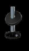
Application:
Material type:
Electrically:
IP Code IP69K
Chemical resistance:
Color:
Flammability:
Range of temperature:
Max. temperature:
Compliance with:
Foot base for NGI plastic feet
PA 6
Non-conductive
DIN (Deutsches Institut für Normung) 40050-9
High to commonly applied cleaning agents
Black
V2
Min. -20 C to max. +110 º C
High thermal resistance for short duration: +150 º C
REACH 2037/2000, 2023/2006 EC, No Phthalates, FDA approved
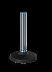
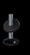
Application:
Material type:
Electrically:
Chemical resistance: Color:
Hardness:
Range of temperature: Load:
TPE
Non-conductive
High to commonly applied cleaning agents
Black
Shore A 90 +/- 5
Min. -50 C to max. +125 º C
High load capacity
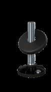
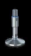
Application:
Material type:
Electrically:
Chemical resistance: Color:
Hardness:
Range of temperature: Load:
slip
EPDM/NBR
Non-conductive
High to commonly applied cleaning agents
Black
Shore A 80 +/- 5
Min. -20 C to max. +110 º C
Low load capacity
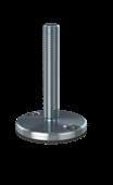
The nominal load specifcations below are for the footplates only. Maximum nominal load = lowest value for footplate or spindle. 3A,
XHS065, XHS066, XHS080, XHS081, XHTS65, XHTS066, XHTS080, XHTS081, XHF065, XHF066, XHF080, XHF081
M040, M050, M075, M076, M077, M105, M106. H060, H061, H080, H081, H082, HT060, HT080
M040, M050, M075, M076, M077, M105, M106, H060, H061, H080, H081, H082, HT060, HT080, K075, HX065, HX066, HX080, HX081, HXT080
XHS105, XHS106, XHS125, XHTS105, XHTS106
H100, H101, H120, H140, HT100, HT120, HT140, M100, M125, M150, H120, H140, HG060AS, HG070AS, HG090AS, HG110AS, HG150AS, HGT090AS, HGT110AS, HJT090AS, HJT110AS, HJ080AS, HJ090AS, HJ110AS, HJ150AS,
HT100, HT120, HT140, K100, K125, HX105, HX106, HX125, M100, M125, M150, H120, H140
CF110AS, CF180AS, G090AS, G110AS, G150AS, G180AS, G200AS, HG060AS, HG070AS, HG090AS, HG110AS, HG150AS, HGT090AS, HGT110AS, HJ080AS, HJ090AS, HJ110AS, HJ150AS, J090AS, J110AS, J150AS, J180AS, KCF110AS, KG090AS, KG110AS, KG150AS, KG180AS, KJ090AS, KJ110AS, KJ150AS, KJ180AS, KT090AS, KT110AS, KT130AS, KT150AS, KT180
HPA040, HPA040AS, HPA050, HPA050AS, HPA060, HPA060AS, HPA080, HPA080AS, HPA081, HPA081AS, HPA100, HPA100AS, HPA101, HPA101AS, HP060, HP080, HPG060, HPG080, HPR08 20.000
HP100, HP120, HPG100, HPG 120, HPR100, HPR120, HPA125, HPA125AS
XHS150, XHTS150, XHGS105, XHGS125, XHGS150, XHGTS105, XHGTS125, XHGTS150, XHJS105, XHJS125, XHJS150, XHJTS105, XHJTS125, XHJTS150
HG060, HG070, HG090, HG110, HG150, HJ080, HJ090, HJ110, HJ150
HX150 CF110, G090, G110, G150, J090, J110, J150, KG090, KG110, KJ090, KJ110, HG060, HG070, HG090, HG110, HG150, HJ080, HJ090, HJ110, HJ150, KCF110, HXG105, HXG105AS, HXG125, HXG125AS, HXGT105, HXGT105AS, HXGT125, HXGT125AS, HXJ105, HXJ105AS, HXJ125, HXJ125AS, HXJT105, HXJT105AS, HXJT125, HXJT125AS
CF180, G180, J180, KG150, KG180, KJ150, KJ180, KT090, KT110, KT130,
KT150, KT180
HGT090,
When selecting the levelling foot we recommend to follow the below factors.
For optimal levelling of the machinery we recommend to follow the below guidelines.
Spindle destabilisation
The spindle must have the right diameter in relation to the length to avoid destabilisation.
Load combination
Maximum nominal load = lowest value for footplate or spindle.
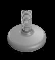
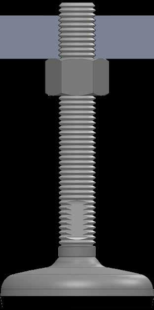
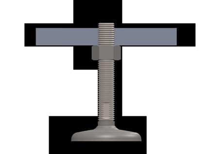
Thread engagement
The thread length of engagement (L) must be selected according to the load on the levelling foot.
Spindle yield
The spindle diameter must be selected according to the load on the levelling foot to avoid spindle yield.
Horisontal levelling
The machinery must be horisontally levelled.

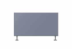
Even load
If the machinery has an uneven weight distribution, the feet should be placed according to the distribution of weight.
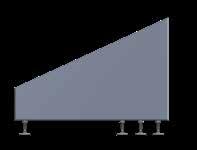
Load distribution
To avoid overload of the machinery the levelling feet should be adjusted with the same torque.
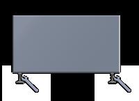
Sloping floor
For correct installation the maximum slope of the floor must not exceede the specifcations of the levelling foot.


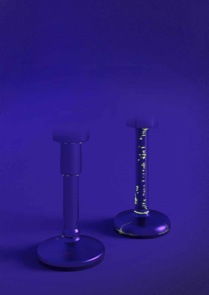
• THE CERTIFIED HYGIENIC LEVELLING FOOT IS CLEAN
• THE SPINDLE OR THE FULLY-THREADED LEVELLING FOOT IS INFECTED WITH BACTERIA
• FULLY-THREADED VS HYGIENIC - IT TAKES 28% MORE RESSOURCES TO REACH THE SAME LEVEL OF CLEANABILITY ON A FULLY-THREADED FOOT
• RESSOURCES COULD BE TIME, WATER, MONEY, DETERGENTS, ETC.


The resources required to clean NGI’s levelling feet depends largely on the design of the levelling foot and the environment in which the levelling foot is used.
It is possible to use all known detergents to clean the levelling feet as long as the instructions provided by the supplier is complied with.
1.0 Scope of application of terms and conditions of sale
1.1 These terms and conditions of sale apply to all NGI A/S (“NGI”) ofers, sales and deliveries of products to the buyer (the Buyer”) unless otherwise accepted by NGI in writing.
1.2 NGI and the Buyer have not entered into a fnal and binding agreement of sale until NGI has issued a written order confrmation, which shall constitute such fnal and binding agreement.
2.0 Delivery terms
2.1 Products are delivered EX WORKS/ab fabrik from NGIs place of business (Virkelyst 5, 9400 Nørresundby, Denmark). Products are delivered in NGI’s standard packaging.
2.2 If NGI and the Buyer have agreed that NGI shall arrange for transport of the products to the Buyer, NGI will stipulate the expected date of delivery in the applicable order confrmation. Any such transport will be at the cost and risk of the Buyer unless otherwise explicitly agreed by the parties in writing.
2.3 Delivery dates are best estimates only. NGI shall not be liable for delays.
3.0 Terms of payment
3.1 NGI ofers the Buyer the number of days of credit specifed in the relevant invoice. However, NGI may demand prepayment at any time if NGI considers this to be relevant.
3.2 If payment is not made before or on the due date specifed in the relevant invoice, NGI is entitled to charge interest on the due amount from the due date at a rate of 2% per commenced month.
3.3 NGI reserves title in the products until the products have been paid for in full.
4.0 Defects and liabilty
4.1 NGI is obliged to, at its choice, repair or replace defective products on the terms set out in clauses 4.2 - 4.9 below.
4.2 The buyer shall complain in writing to NGI of a defect immediately after such defect has been or should have been discovered and in any event within one year from delivery. The complaint shall describe the alleged defect in reasonable detail. If the Buyer does not complain in accordance with the aforesaid, the Buyer will lose his right to raise claims against NGI for products being defective. If a product has been used more intensively than agreed or assumed, the complaints period shall be reduced proportionally.
4.3 Repair or replacement of products or parts does not extend the maximum complaints period of one year in clause 4.2.
4.4 If NGI decides to repair a defective product, repair shall take place on site. If NGI decides to replace a defective product, replacement will be efected by NGI sending a non-defective product to the Buyer. Repair or replacement shall be efected by NGI within reasonable time after NGI receives a complaint in accordance with clause 4.2, and in any event with 4 weeks from receipt of such complaint, 4.5 NGI may demand that (alleged) defective products are returned to NGI at the Buyer’s risk and cost. Returned products shall become NGIs property if replaced. If the Buyer complains about a product that NGI subsequently establishes not be defective, NGI may claim compensation for its time, work, costs etc. in accordance with its terms, rates and prices applicable from time to time.
4.6 If NGI does not fulfll its obligations under clause 4.4, the Buyer shall have the right to return the defective product to NGI, at the Buyer’s cost and risk, for a full refund of the purchase price.
4.7 NGI shall not be responsible for defects caused by material which is provided by the Buyer, for constructions or specifcation which are prescribed or specifed by the Buyer, for inadequate maintenance, for changes to the delivered products made without NGI’s prior written consent, for inappropriate repairs or incorrect use of the products, or for faulty preparatory work by the Buyer. NGI’s liability only includes defects which appear under working conditions presumed by NGI. Normal wear and tear and depreciation shall not be considered a defect.
4.8 NGI’s liability under this Agreement shall be limited to the invoice value of the defective product, that gave rise to claim. Further, NGI shall not be liable for indirect loss, including loss of operation, lost earnings and other consequential loss. The limitation of NGI’s liability shall not apply if NGI acted grossly negligently or intentionally.
4.9 NGI shall be liable only to the extent set out above in this clause 4. The rights and remedies of the Buyer set out in this clause 4 are exhaustive and exclude all other remedies and claims under law or otherwise.
5.1 NGI shall be responsible for product liability claims only to the extent required under mandatory product liability law. NGI shall not be liable for damage to commercial property. Further, NGI shall not be liable for indirect loss, including loss of operation, lost earnings and other consequential loss.
If a third party raises a claim against the Buyer for product liability, the Buyer shall immediately notify NGI in writing.
6.0
6.1 Any disputes between the Parties arising from or in connection with NGI’s sales of products to the Buyer shall be governed by substantive Danish law (and the CISG shall not be applicable), and disputes shall be brought before The Maritime and Commercial Court (Sø- og Handelsretten) in Copenhagen, Denmark. If this court declares that it is not competent, disputes shall be brought before the Copenhagen City Court (Københavns Byret) in Copenhagen, Denmark.
Date of publication: April 2020
All information in this product catalogue is subject to change without prior notice.
(C) All Rights Reserved
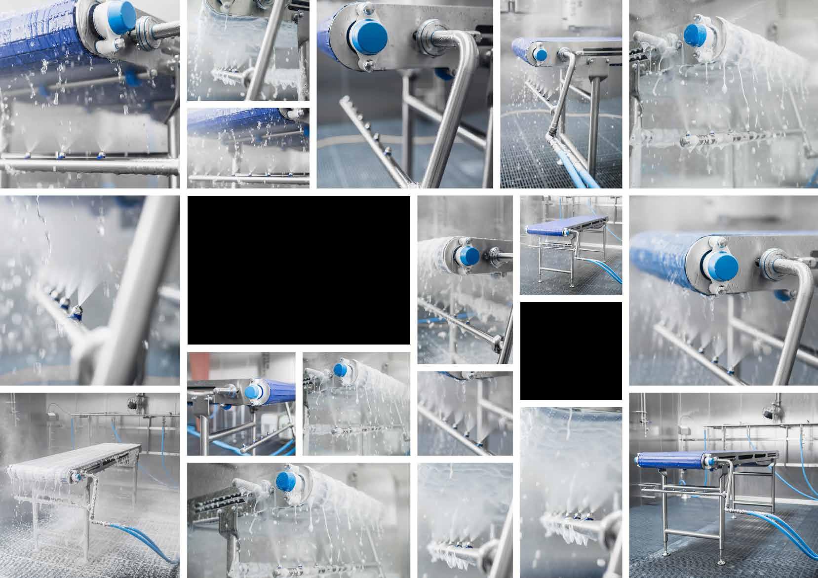
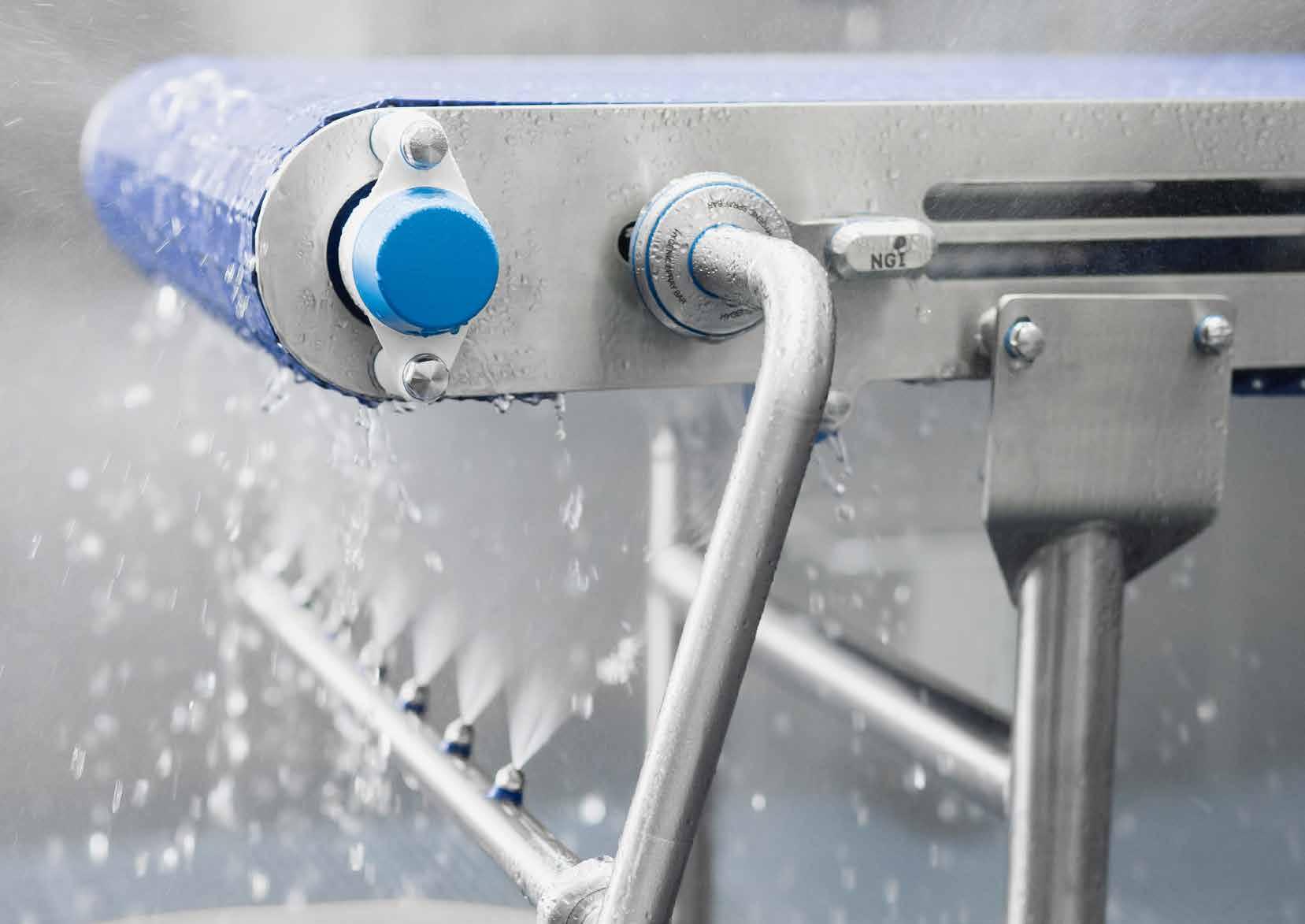
The new easy-to-ft hygienic CIP unit is a simple and efficient solution, where nozzles are positioned on the two spray bars. This is to efectively remove the accumulated organic residues from both sides of a process and conveyor belting.
The CIP unit can easily be installed with no use of complicated engineering and conveyor frame modifcations. The device is highly efficient, hygienically designed, and makes cleaning more environmentally friendly.
The installation of the new CIP unit minimizes the operator’s manual cleaning and contributes to reduce the resource utilization such as water, labor and detergents. See more at www.ngi-global.com
• Reduce the cleaning time and manual labor and increase your production time
• Reduce the consumption of water, chemicals and energy
• Minimize the wear on conveyor belt surfaces by avoiding manual cleaning
• Low maintenance and service required
• State-of-the-art hygienic design. Inspired by EHEDG and 3-A design guidelines A safer and more effective cleaning of your