Topics in Modal Analysis & Testing, Volume 8: Proceedings of the 37th IMAC, A Conference and Exposition on Structural Dynamics 2019 Michael L. Mains
Visit to download the full and correct content document: https://textbookfull.com/product/topics-in-modal-analysis-testing-volume-8-proceeding s-of-the-37th-imac-a-conference-and-exposition-on-structural-dynamics-2019-michael -l-mains/
More products digital (pdf, epub, mobi) instant download maybe you interests ...
Topics in Modal Analysis Testing Volume 8 Proceedings of the 38th IMAC A Conference and Exposition on Structural Dynamics 2020 1st Edition Brandon Dilworth
https://textbookfull.com/product/topics-in-modal-analysistesting-volume-8-proceedings-of-the-38th-imac-a-conference-andexposition-on-structural-dynamics-2020-1st-edition-brandondilworth/
Special Topics in Structural Dynamics & Experimental Techniques, Volume 5: Proceedings of the 37th IMAC, A Conference and Exposition on Structural Dynamics 2019 Nikolaos Dervilis
https://textbookfull.com/product/special-topics-in-structuraldynamics-experimental-techniques-volume-5-proceedings-ofthe-37th-imac-a-conference-and-exposition-on-structuraldynamics-2019-nikolaos-dervilis/
Dynamics of Civil Structures, Volume 2: Proceedings of the 37th IMAC, A Conference and Exposition on Structural Dynamics 2019 Shamim Pakzad
https://textbookfull.com/product/dynamics-of-civil-structuresvolume-2-proceedings-of-the-37th-imac-a-conference-andexposition-on-structural-dynamics-2019-shamim-pakzad/
Nonlinear Structures and Systems, Volume 1: Proceedings of the 37th IMAC, A Conference and Exposition on Structural Dynamics 2019 Gaetan Kerschen
https://textbookfull.com/product/nonlinear-structures-andsystems-volume-1-proceedings-of-the-37th-imac-a-conference-andexposition-on-structural-dynamics-2019-gaetan-kerschen/
Special Topics in Structural Dynamics, Volume 5: Proceedings of the 36th IMAC, A Conference and Exposition on Structural Dynamics 2018 Nikolaos Dervilis
https://textbookfull.com/product/special-topics-in-structuraldynamics-volume-5-proceedings-of-the-36th-imac-a-conference-andexposition-on-structural-dynamics-2018-nikolaos-dervilis/
Model Validation and Uncertainty Quantification, Volume 3: Proceedings of the 37th IMAC, A Conference and Exposition on Structural Dynamics 2019 Robert Barthorpe
https://textbookfull.com/product/model-validation-anduncertainty-quantification-volume-3-proceedings-of-the-37th-imaca-conference-and-exposition-on-structural-dynamics-2019-robertbarthorpe/
Sensors and Instrumentation, Aircraft/Aerospace, Energy Harvesting & Dynamic Environments Testing, Volume 7: Proceedings of the 37th IMAC, A Conference and Exposition on Structural Dynamics 2019 Chad Walber
https://textbookfull.com/product/sensors-and-instrumentationaircraft-aerospace-energy-harvesting-dynamic-environmentstesting-volume-7-proceedings-of-the-37th-imac-a-conference-andexposition-on-structural-dynamics-2019-chad/
Dynamics of Coupled Structures Volume 4 Proceedings of the 34th IMAC A Conference and Exposition on Structural Dynamics 2016 1st Edition Matt Allen
https://textbookfull.com/product/dynamics-of-coupled-structuresvolume-4-proceedings-of-the-34th-imac-a-conference-andexposition-on-structural-dynamics-2016-1st-edition-matt-allen/
Sensors and Instrumentation, Aircraft/Aerospace and Energy Harvesting, Volume 8 Proceedings of the 36th IMAC, A Conference and Exposition on Structural Dynamics 2018 Evro Wee Sit
https://textbookfull.com/product/sensors-and-instrumentationaircraft-aerospace-and-energy-harvesting-volume-8-proceedings-ofthe-36th-imac-a-conference-and-exposition-on-structuraldynamics-2018-evro-wee-sit/
Michael L. Mains · Brandon J. Dilworth Editors
Topics in Modal Analysis & Testing, Volume 8 Proceedings of the 37th IMAC, A Conference and Exposition on Structural Dynamics 2019
SeriesEditor KristinB.Zimmerman,Ph.D. SocietyforExperimentalMechanics,Inc., Bethel,CT,USA
Moreinformationaboutthisseriesat http://www.springer.com/series/8922
MichaelL.Mains•BrandonJ.Dilworth Editors
Proceedingsofthe37thIMAC,AConferenceandExposition onStructuralDynamics2019
Editors
MichaelL.Mains
MechanicalandMaterialsEngineering CollegeofEngineeringandAppliedSciences FacultyAdvisor,BearcatMotorsports UniversityofCincinnati Cincinnati,OH,USA
BrandonJ.Dilworth LincolnLaboratory MassachusettsInstofTechnology Lexington,MA,USA
ISSN2191-5644ISSN2191-5652(electronic)
ConferenceProceedingsoftheSocietyforExperimentalMechanicsSeries
ISBN978-3-030-12683-4ISBN978-3-030-12684-1(eBook) https://doi.org/10.1007/978-3-030-12684-1
©SocietyforExperimentalMechanics,Inc.2020
Thisworkissubjecttocopyright.AllrightsarereservedbythePublisher,whetherthewholeorpartofthematerialisconcerned,specificallytherights oftranslation,reprinting,reuseofillustrations,recitation,broadcasting,reproductiononmicrofilmsorinanyotherphysicalway,andtransmissionor informationstorageandretrieval,electronicadaptation,computersoftware,orbysimilarordissimilarmethodologynowknownorhereafterdeveloped. Theuseofgeneraldescriptivenames,registerednames,trademarks,servicemarks,etc.inthispublicationdoesnotimply,evenintheabsenceofaspecific statement,thatsuchnamesareexemptfromtherelevantprotectivelawsandregulationsandthereforefreeforgeneraluse.
Thepublisher,theauthors,andtheeditorsaresafetoassumethattheadviceandinformationinthis bookarebelievedtobetrueandaccurateatthedate ofpublication.Neitherthepublishernortheauthorsortheeditorsgiveawarranty,expressorimplied,withrespecttothematerialcontainedhereinorfor anyerrorsoromissionsthatmayhavebeenmade.Thepublisherremainsneutralwithregardtojurisdictionalclaimsinpublishedmapsandinstitutional affiliations.
ThisSpringerimprintispublishedbytheregisteredcompanySpringerNatureSwitzerlandAG. Theregisteredcompanyaddressis:Gewerbestrasse11,6330Cham,Switzerland
Preface TopicsinModalAnalysis&Testing representsoneofeightvolumesoftechnicalpaperspresentedatthe37thIMAC,A ConferenceandExpositiononStructuralDynamics,organizedbytheSocietyforExperimentalMechanicsandheldin Orlando,Florida,January28–31,2019.ThefullproceedingsalsoincludevolumesonNonlinearStructures&Systems; DynamicsofCivilStructures;ModelValidationandUncertaintyQuantification;DynamicsofCoupledStructures;Special TopicsinStructuralDynamics&ExperimentalTechniques;RotatingMachinery,OpticalMethods&ScanningLDV Methods;andSensorsandInstrumentation,Aircraft/Aerospace,EnergyHarvesting&DynamicEnvironmentsTesting.
Eachcollectionpresentsearlyfindingsfromexperimentalandcomputationalinvestigationsonanimportantareawithin structuraldynamics.TopicsinModalAnalysisrepresentspapersonenablingtechnologiesformodalanalysismeasurements andapplicationsofmodalanalysisinspecificapplicationareas.
Theorganizerswouldliketothanktheauthors,presenters,sessionorganizers,andsessionchairsfortheirparticipationin thistrack.
Cincinnati,OH,USA
Lexington,MA,USA
MichaelL.Mains
BrandonJ.Dilworth
Contents 1ModernModalTesting:ACautionaryTale ..........................................................................1 JamesC.Akers,KimD.Otten,JoelW.Sills,andCurtisE.Larsen
2VibrationTestingofLaparoscopicSurgicalInstrumentsUnderVaryingGripPressures ......................9 AndrewR.Hutchins,SabinoZaniJr.,RobertoJ.Manson,andBrianP.Mann
3CombinedQualificationVibrationTestingandFixedBaseModalTestingUtilizingaFixedBased CorrectionMethod ......................................................................................................13 JamesP.Winkel,VicenteJ. Suárez,andJamesC.Akers
4PressureStiffenedModalCorrelationofaCylindricalPressureVessel ...........................................31 EmilyA.JewellandIsamYunis
5PretestAnalysisforModalSurveyTestsUsingFixedBaseCorrectionMethod .................................39 PeterKerrianandKevinL.Napolitano
6FixingDegreesofFreedomofanAluminumBeambyUsingAccelerometersasReferences
KevinL.Napolitano
7SignalReconstructionfromMobileSensorsNetworkUsingMatrixCompletionApproach ...................61 SoheilSadeghiEshkevariandShamimN.Pakzad
8AllVibrationIsaSummationofModeShapes .......................................................................77 BrianSchwarz,PatrickMcHargue,JasonTyler,andMarkRichardson
9ModalTestingUsingtheSlinkyMethod ..............................................................................93 BrianSchwarz,PatrickMcHargue,andMarkRichardson
10NumericalandExperimentalModalAnalysisofaCantileverBeamAxiallyLoadedbyaTendon WhichIsAttachedinaSingleSpanwiseLocation ...................................................................107 VaclavOndraandBranislavTiturus
11DesigningaModalTestPlanBased onFiniteElementMethodResults ..........................................117 YanCaoandLiuJinming
12MaximizingtheQualityofShapeExtractionsfromBaseShakeModalTests ....................................123 KevinL.Napolitano
13NewApproachestoInverseStructuralModificationTheoryUsingRandomProjections ......................127 PrasadCheema,MehrisadatM.Alamdari,andGarethA.Vio
14ModalAnalysisofWindTurbineBladeswithDifferentTestSetupConfigurations .............................143 E.DiLorenzo,S.Manzato,B.Peeters,V.Ruffini,P.Berring,P.U.Haselbach,K.Branner,andM.M.Luczak
15ModalExcitationofCircularRotatingStructuresUsinganInnovativeElectromagneticDevice ..............153 ThomasHoffmann,MartinJahn,LarsPanning-vonScheidt,andJörgWallaschek
16ModalAnalysisofa7DoFSweetPepperHarvestingRobot .......................................................163 TobiasF.C.Berninger,SebastianFuderer,andDanielJ.Rixen
17CharacterizingDynamicsofAdditivelyManufacturedParts ......................................................171 GaryAdkins,ClaytonLittle,PeterMeyerhofer,GarrisonFlynn,andKyleHammond
18HowLinearIsaLinearSystem? .......................................................................................185 D.Roettgen,B.Pacini,andB.Moldenhauer
19AnInterpolationAlgorithmtoSpeedUpNonlinearModalTestingUsingForceAppropriation ..............193 MichaelKwarta,MatthewS.Allen,andJosephJ.Hollkamp
20EstimatingAppliedLoadsandResponseAccelerationsonaDynamicSystemUsingVibrationData ........197 ErenKoçak,CanerGenço ˘ glu,BülentAcar,andKenanGürses
21AnalysisofCouplingRelationshipBetweenCar-BodyandFlexibleHangingEquipment ......................209 XiaoningCao,XiugangWang,QintaoGuo,AiqinTian,ShaoqingLiu,WeiXue,andJiancaiZou
22Imager-BasedCharacterizationofViscoelasticMaterialProperties ..............................................215 HowardBrand,TiaKauppila,KaylaWielgus,BridgetMartinez,NathanMiller,TrevorTippetts, YongchaoYang,andDavidMascareñas
23DevelopmentandValidationofDataProcessingTechniquesforAircraftGroundVibrationTesting
SilviaVettori,EmilioDiLorenzo,BartPeeters,andAntonioCarcaterra
24StructuralHealthMonitoringwithSelf-OrganizingMapsandArtificialNeuralNetworks
OnurAvci,OsamaAbdeljaber,SerkanKiranyaz,andDanielInman
25ANovelTechniquetoExtracttheModalDampingPropertiesofaThinBlade
T.Mace,J.Taylor,andC.W.Schwingshackl
26FiniteElementModelUpdatingoftheUCFGridBenchmarkConnectionsUsingExperimental ModalData ...............................................................................................................251 MiladMehrkashandErinSantini-Bell
27StructuralHealthMonitoringonIndustrialStructuresUsingaCombinedNumerical andExperimentalApproach ...........................................................................................263 FabianKeilpflug,RobertKamenzky,DanielJ.Alarcón,TarunTejaMallareddy,andPeterBlaschke
28ValidationofAutomaticModalParameterEstimatoronaCarBody-in-White
N.Gioia,Pieter-JanDaems,andJ.Helsen
29ModalAnalysisofRotatingTiresinStationaryandRotatingFramesofReference ............................285 MohammadAlbakriandPabloTarazaga
30CombiningMachineLearningandOperationalModalAnalysisApproachestoGainInsightsin WindTurbineDrivetrainDynamics ...................................................................................293 N.Gioia,P.J.Daems,T.Verstraeten,P.Guillaume,andJ.Helsen
31ModalTest-AnalysisCorrelationUsingLeft-HandEigenvectors ..................................................301 RobertN.Coppolino
32ATheoreticalStudyontheGenerationandPropagationofTravelingWavesinStrings .......................311 IsilAnakok,V.V.N.SriramMalladi,andPabloA.Tarazaga
33ShapingtheFrequencyResponseFunction(FRF)ofaMulti-Degree-of-Freedom(MDOF)Structure UsingArraysofTunedVibrationAbsorbers(TVA) .................................................................317 CampbellR.Neighborgall,KaranKothari,V.V.N.SriramMalladi,PabloTarazaga,SaiTejParuchuri, andAndrewKurdila
34ExperimentalStudyonTireVibrationsandInducedNoise ........................................................327 SterlingMcBride,SeyedmostafaMotaharibidgoli,MohammadAlbakri,RicardoBurdisso,PabloTarazaga, andCorinaSandu
35OntheAdaptiveVibrationSuppressiononaFlexibleSpatialStructure .........................................333 OscarA.Garcia-Perez,LuisG.Trujillo-Franco,andGerardoSilva-Navarro
36EvaluationoftheHuman-Structure-SoilInteractiononaTwo-WheelTractorUsingModalAnalysis Techniques ................................................................................................................341
E.Velazquez-Miranda,G.Silva-Navarro,J.Bory-Reyes,O.A.Garcia-Perez,andL.G.Trujillo-Franco
37ReproducibleModalTestingUsingaFlexure-BasedImpactExcitationSystem
ShivangShekharandO.BurakOzdoganlar
38ModalAnalysisandCharacterizationofMountingCartUsedforTestingintheCombined EnvironmentAcousticChamber .......................................................................................353 MelissaA.Hall
39EffectsofSensorCountonDampingEstimatesfromOperationalModalAnalysis .............................357 EsbenOrlowitz
40AmbientVibrationTestsandModalResponseAnalysisofanOldAgeHigh-RiseBuilding inDowntownVancouver,Canada ......................................................................................365 M.Motamedi,C.E.Ventura,P.Adebar,andR.A.Murugavel
41SystemIdentificationofaFullScaleWoodFrameBuildingSpecimenSubjectedtoShakeTableTests ......369 M.MotamediandC.E.Ventura
42EstimatingRotorSuspensionParametersfromRunoutData ......................................................373 BrianDamiano
Chapter1 ModernModalTesting:ACautionaryTale JamesC.Akers,KimD.Otten,JoelW.Sills,andCurtisE.Larsen
Abstract Overthepast50years,greatadvanceshavehappenedin bothanalyticalmodalanalysis(i.e.,finiteelement modelsandanalysis)andexperimentalmodalanalysis(i.e.,modaltesting)inaerospaceandotherfields.Withtheadvent ofmorepowerfulcomputers,higherperformanceinstrumentationanddataacquisitionsystems,andpowerfullinearmodal extractiontools,today’sanalystsandtestengineershaveabreadthanddepthoftechnicalresourcesonlydreamedofbyour predecessors.However,someobservedrecenttrendsindicatethathardlessonslearnedarebeingforgottenorignored,and possiblyfundamentalconceptsarenotbeingunderstood.Thesetrendshavethepotentialofleadingtothedegradationofthe qualityofandconfidenceinbothanalyticalandtestresults.Thesetrendsareamakingofourowndoing,anddirectlyrelated tohavingevermorepowerfulcomputers,programmaticbudgetarypressurestolimitanalysisandtesting,andtechnical capitallossduetotheretirementoftheseniordemographiccomponentofabimodalworkforce.Thispaperendeavorsto highlightsomeofthemostimportantlessonslearned,commonpitfallstohopefullyavoid,andpotentialstepsthatmaybe takentohelpreversethistrend.
Keywords Analyticalmodalanalysis·Bimodalworkforce·Experimentalmodalanalysis·Finiteelementanalysis· Finiteelementmodel·Lessonslearned·Modaltesting·Retirement
1.1Introduction Analyticalmodalanalysis(i.e.,finiteelementmodellingandanalysis)andexperimentalmodalanalysis(i.e.,modaltesting) haveadvancedgreatlyoverthepast50years.Today’spowerfulcomputers,highperformanceinstrumentationanddata acquisitionsystems(DAQ’s),andpowerfullinearmodalextractiontoolscanprovidetoday’smodaltest/analysisengineer thetechnicalresourcesneededtocompeten tlytacklemost,ifnotall,linearstructuralissues.However,evenwiththisbreadth anddepthoftechnicalresources,today’smodaltest/analysisengineerisstillonlyasgoodastheirtechnicalexpertise.Forus “seasonedveterans”thistechnicalexpertisewasgainedduringthecourseof30+ yearsofworkingandstudyintheaerospace fieldandthroughtheexceptionalmentoring wereceivedfrommanyseniorknowledgeableprofessionals.Itwasthroughthis exceptionalmentoringthatwewereabletoleveragetheexpertiseofthe“seasonedveterans”thatcamebeforeusandavoid makingmanypoor(andquitefranklysimple/unwise)mistakes.Itissaid“Goodjudgementcomesfromexperience,and experiencecomesfrombadjudgement[1].”Unfortunately,ormaybefortunately,organizationsdonothavetheluxuryof beingabletoallowtheirengineerstomakebadjudgements. Thatsaid,recenttrendsobservedinbothindividualengineers andinengineeringorganizationsindicatethehardlessonslearnedoverthepast50yearsarebeingforgottenorignored, andpossiblyfundamentalconceptsarenotbeingunderstood.Thesetroublingtrendshavethepotentialofleadingtothe degradationinthequalityofandconfidenceinbothanalyticalandtestresultsandincreaserisktotheproject.Ifthishappens thecredibilityandefficacyofourengineeringprofessionwillcomeintoquestionandmissionsmaypotentiallysuffer.
Tosomeextent,theseproblemsareamakingofourowndoing.Withtheadventofmodernportablehighpowercomputers anduserfriendlyautomatedsoftware,itisrelativelyeasyforanoviceengineertogenerateacomputeraided-design(CAD) modelofastructure,automeshittogenerateafiniteelementmodel(FEM),andperformstaticandmodalanalysis
J.C.Akers( )·K.D.Otten
NASAGlennResearchCenter,Cleveland,OH,USA e-mail: james.c.akers-1@nasa.gov
J.W.Sills NASAJohnsonSpaceCenter,Houston,TX,USA
C.E.Larsen
DepartmentofEngineering,TexasChristianUniversity,FortWorth,TX,USA
©SocietyforExperimentalMechanics,Inc.2020
M.L.Mains,B.J.Dilworth(eds.), TopicsinModalAnalysis&Testing,Volume8,ConferenceProceedingsoftheSocietyfor ExperimentalMechanicsSeries, https://doi.org/10.1007/978-3-030-12684-1_1
(i.e.,computestresses,strains,modalfrequencies,andmodeshapes).Alsoanoviceengineercancollecttestdata(i.e., force,acceleration,andstraintimehistories),postprocessit,andextractmodalparameters(i.e.,modalfrequencies,mode shapes,andmodaldamping).Inaworkforcewherethereareampleseasonedengineeringprofessionalshelpingtoguide andmentorlessexperiencednoviceengineerstoavoidcommonpitfallsandreinforcetheunderlyingengineeringtheoretical concepts,thesemoderncapabilitiesareatrueasset.Eveninorganizationsthathaveabimodalworkforcewherethereare mostlyveryseasonedandverynoviceengineers,amplementoringcanhelptomakeupfortheshortfallofnothavingmany, ifany,mid-careerengineers.Howeverinorganizationswherethecurrentandforeseeableprogrammaticbudgetarypressures arelimitingtheamountofanalysisandtesting,combinedwiththeirtechnicalcapitallossduetotheretirementoftheirsenior seasonedprofessionals,whichcurtailsmuchneededmentori ng,theearlycareernoviceengineersareleft“notknowingwhat theydon’tknow”.Whilethefocusofthispaperisonaerospaceengineersperformingmodal/vibrationtestingorperforming analysiswithFEM’s,theconcernsdiscussedhereapplytomanyengineeringdisciplines.Thegoalofthispaperistoprovide earlycareernoviceengineerswithsomekeyconceptstohelpavoidthemostcommonpitfalls,andtoprovideboththem andeveryoneintheirorganizationpotentialstepsforensuringtheirorganization’stechnicalexpertiseremainsviableandthe aerospaceengineeringprofession remainsvibrantandrelevant.
1.2Pitfall#1:ConfusingComputerJockeysandEngineers Asengineerswemustunderstandthekeyfundamentalphysicsbasedconceptsthatunderpinouranalysisandtestingand realizethatsoftwareandhardwarearetools,notcrutchestomakeupforourlackofunderstanding.Wemustbeableto notonlyprovideresults,butbeabletoverifyandvalidatethoseresults.Beingabletomake“simplebackoftheenvelope calculations”isofparamountimportancetoprovidesanitychecks.Thisisevenmorecritical intoday’sworkenvironment whereengineersareincreasinglyoperatingasan“armyofone”andthedoublechecksandfactcheckingthatoccurredin thepastarehappeninglessandlessfrequently,ifatall.If youcandrawthefreebodydiagramofasingledegreeoffreedom (SDOF)oscillator,deriveitsequationofmotion,solveforits impulseresponsefunction,solveforthefrequencyresponse function,beabletoplotthesefunctionsandunderstandthem,youare90%ofthewaytounderstandingmostvibration problems.Theoldadage“KeepItSimpleandStraightforward”(KISS)isasrelevanttodayasinthepast.Startsimplyin youranalysis/testingandonlyaddcomplexityasneeded.Don’tconfusecomplexityforsophistication.Manytimesthemost sophisticatedsolutionmethodisthesimplest.Remember,wewenttotheMoononFEM’shavingonlycenterlinegridpoints andbeamelements,morecommonlyreferredtoas“ball-stickmodels.”TheSaturnVlaunchvehiclewasinitiallymodeled inthismannerduringtheApolloprogram[2, 3].Somehowmilliondegreeoffreedom(DOF)FEM’swerenotrequired(and neitherwastheInternet).
1.3Pitfall#2:TooMuchBlindFaithinFEM’s “AllMODELSAREWRONGBUTSOMEAREUSEFUL[4].”Thisblindfaithisthedirectresultofhavingextremely powerfulcomputersallowingrelativelynoviceengineerstogenerateCADmodelsthatlookexactlylikethehardwareand inturnusingautomeshfeaturestogenerateFEM’sthatlookexactlylikethehardware.“Prettypicturesdonotagood modelmake.”ThishasledsomedecisionmakerstobelievethataccurateCADmodelsandFEM’scanbeaccomplished withinexperienced(a.k.a.inexpensive)engineers.This issimplynottrue.AfinelymeshedFEMdoesnotguaranteeit accuratelycapturesthestructuralcharacteristics(i.e.,loadpaths)oftheactualhardware.Itonlymeansthesamemodelling assumptionshavebeenmademany,many,manytimesandiftheseassumptionsareincorrectthentheresultingFEMwill stillbeinaccurate.AlsothereisacurrenttrendofusingthestressFEMastheloadsFEM.ThestressFEMhasveryfine meshingtoaccuratelycapturetheintricaciesofstressfieldsaroundjointsandfasteners.TheloadsFEMdoesnotrequireas fineameshingsinceitisintendedtocapturethestructural dynamicpropertiesandneedstoallowreasonablemodalanalysis runtimes.ThevalidityofCADmodelsandFEM’sishighlydependentupontheproficiencyandexperienceoftheengineer generatingthem.TheengineergeneratingtheFEMneedstousetheappropriateelementsinsteadofsimplyrelyingonautomeshingthatpickselementtypesbaseduponeaseofmeshinginsteadofthebehavioroftheunderlyingstructure.Similarly, theFEMautomaticsinglepointconstraint(AUTOSPC)featureshouldbeavoidedsotheengineerisforcedtounderstand whatDOFareconstrainedandunconstrainedintheFEMandwhy.RememberthatuntilaFEMhasbeen“grounded”to testdata(i.e.,correlatedtostaticandmodaltestdata),itsaccu racy/validityisuncertain.Incorporationofstatictestresults intoaFEMcorrelationtoobtainthecorrectstiffnessishalfthebattle—neverforgetthedynamicsideoftheequation
(i.e.,squareroot(k/m)).Formodaltestingpretestanalysis,thismeanshavingahealthyskepticismoftheFEMaccuracy andalwaysincorporatingmarginintotestpreparations(e.g.,skewingshakerstohelpensurethatallTargetModeswillbe adequatelyexcited,instrumentationattheboundarytoverifytheboundaryconditionsduringtesting,usingengineering judgementalongwithsuchtoolsasiterativekineticenergytoselectinstrumentationlocations).
1.4Pitfall#3:ConfusingBeingBusywithBeingProductive Avoidconfusingbeingbusywithbeingproductive.Peoplenaturallywanttofeelthattheyaremakingprogresstowards reachingtheirendgoalanditisnaturaltoassumethatiftheyarebusydoingsomethinginsteadofbeing“idle”,thentheyare surelymakingprogress.Nottrue.Takethenecessarytimetoplan,prioritize,anddefinetheobjectives,goals,andsuccess criteriaofthetask.Thiswillallowyoutofocusyourtimeand resourcestogiveyouthehighestprobabilityofsuccessfully completingyourtask.Notetherearenocertaintiesandyoumustrealizethatyoudonotcontroleverything.Hence,wecan onlyspeakofprobabilitiesandlikelihoodsofsuccess.
1.5Pitfall#4:AvoidRushingtoAnalyze Itisverytemptingwhenfirstgivenamodelordatatowanttojumprightinandstartperformingyouranalysis.SeePitfall #3.However,itisimportanttoperform“sanitychecks”onanymodelsordatapriortoperforminganyanalysisinorder toavoidworkingforweeksonlytodiscoveritwasallfornaughtbecauseofeitherafaultymodelorcorrupteddata.Be skepticalofFEM’sprovidedtoyouandperformyourownstandardmodelchecks,especiallyifthepreviousFEManalysis residesinadifferentversionofsoftwarethanyouareusingbecausedefaultsettingscanchange[5].BesuretheFEMhas beenvalidatedtomatchtheCADoras-builthardware.AFEMisnotvalidjustbecauseithasbeen“correlated”tomodal parametersextractedfromamodaltestorresultsfromastaticstiffnesstest.TakingthetimetomatchtheFEMtotheCAD oras-builthardwareisabsolutelycritical foraccuratelycapturingtheloadpathsandbeingabletopredictinternalloads[6]. Moreover,whentheFEMmatchestheCADoras-builthardware,90–95%ofthemodelcorrelationeffortisachieved.Ifthe FEMdoesnotaccuratelyrepresenttheCADoras-builthardware,themodelcorrelationeffort, whilebeinginaccurate,most likelywillalsobeextremelydifficultandtimeconsumingandprobablyleadtounmetrequirementsandscheduleconstraints. BesureyouunderstandtheunitstheFEMisinandthedataunits.Eventhoughitisthetwenty-firstcentury,manyFEM’s generatedandusedbyUScompaniesstillhavemassinunitsofslinchesandslugsandaccelerationdatacanbeinunitsof in/s2 org’s.Don’tforgetfrequenciescanbeinunitsofrad/sorHz.Whendoingyourchecks,ifyouareoffbyafactorof 9.8,thisisprobablyanaccelerationunitsissueandifyouareoffbyafactorof6.3(i.e.,2π),thisisprobablyafrequency unitsissue.
Similarlybeskepticalofdataprovidedtoyou,andifpossible,performtime-domainand frequencydomaindataquality checksasappropriate.Askquestionstotheentityprovidingthedataforpoofofitsvalidity.Forexample,iftimehistorydata hasbeensuppliedandhaseitherbeenclippedorisinthenoisefloorofthedataacquisitionsystemthatwasusedtorecord it,blindlypostprocessingitintospectrawillleadtoverymisleadingspectra,whichisnotself-evident.
Taketimethroughoutyouranalysistoperformintermediatechecks.Withtoday’ssoftwareitisveryeasytoplotresults andgeneratetabularlistings,whichprovidequickandinsightfulcheckingmethods.Forexampleifyouarefilteringtime histories,besuretocomparethefrequencyresponsefunctionofthefiltertothePowerSpectralDensity(PSD)computedon broadbandrandomwhitenoisethathasbeenpassedthroughittoverifythefilter.Itisveryeasyintodesignfiltersthathave verytightpassbands,butarenumericallyunstable.Itisofcriticalimportancetobeabletocompute“backoftheenvelope” calculationsforprovidingatleastcursorysanitychecksofanalyticalresults.Sometechnicalreferencestoconsiderarelisted in[7–24].Documentingtheseintermediateandfinalchecksconstitutetheimportantportionofyouranalysisreportthat verifiesthevalidityofyouranalysisresults.Attheendoftheday,itisyournameandreputationthatisontheline,and itonlytakesoneortwobadanalysestogiveyouanegativereputationinyourorganization,whichcanbeveryhardto overcome.
1.6Pitfall#5:AvoidRushingtoTest Settingupamodaltestandperformingit,canbebothaveryexhilaratingandstressfultime.Itinvolvesphysicalexertion (e.g.,movingshakers,mountingaccelerometers,runningcabling,beinginanunfamiliarlocale),uppermanagementand programmaticpersonnelbeingpresentto“witness”thetesting(i.e.,lookingoveryourshoulder,beinginafishbowl),and havingaverylimitedtimewindowtoaccomplishit.Becauseofthis,itisverynaturaltowanttostartcollectingdataas quicklyaspossible,andinturntostartextractingmodalparametersasquicklyaspossible.However,aswithanalysis,itis importanttotaketimetoverifythetestsetupandthevalidityofthedatabeingcollected.BesuretheDAQhasanti-aliasing filteringengagedandoperating.Withtheadventoffasterandfastercomputers,acommonmisconceptiongoingaroundis thatyoucansamplesofastthataliasingisnolongeranissue.Nottrue.Aliasingwillalwaysbepresentwhateverthesampling rateisandoncetherecordedtimehistorieshavebeencorruptedbyaliasingitisimpossibletocorrectthem.Takethetime toperformtime-domainandfrequency-domaindataqualitychecksduringtestingtoverifythehealthofthechannelsand validityofthetestsetup.
Timedomainchecksshouldincludevisualinspectionofthetimehistories,lookingfordatadropouts,digitizationerror (i.e.,fullscalesettingoftheDAQsettoohigh),clipping(i.e.,fullscalesettingoftheDAQsettoolow),adequatelycapturing peaksinthefrequencyrangeofinterest,andimpulsivespikes indicatingrattlingand/orimpactingtakingplace.Computing standardstatisticssuchasmean,standarddeviation,kurtosis,andcrestfactoronrandomexcitationtestrunsprovideaquick andusefulchecktodetermineifnonlinearbehaviorispresent[25].Keepinmindthatcrestfactors(i.e.,peakdividedby standarddeviation)duringvibrationtestingcanreachashighas 5ormore.However,extremelyhighcrestfactorsandkurtosis mayindicateimpulsivespikesinthetimehistoriesofchannelsgoingbadormeasuringsignificantrattling/impactinginthe testarticle.Itisimportanttomonitorchannelsinrealtimeastheyarebeingacquiredtocheckforunderflow,overflow, excessivemean,signaldrift,andimpulsivespikes.IftheDAQgeneratesanautomaticchannelfaultlog(i.e.,deadchannel, overflow,underflow,etc.)takeadvantageofthisimportantfeature.
Frequencydomainchecksshouldincludeverifyingthedrivepointfrequencyresponsefunction(FRF)hastheexpected phaseanglebehavior(i.e.,foraforcetoaccelerationFRFiftheaccelerometerhasthesameorientationastheloadcellthe phaseanglestaysbetween 180◦ and 360◦ overthedesiredfrequencyrange).ChecktheinputexcitationforcePSDand comparetheresponsePSD’stotheirambientbackgroundlevelstoverifytheexcitationhassufficientfrequencybandwidth andlevel.Checkthecoherenceplotstoverifytherearelinearrelationshipsbetweeninputexcitationforcesandresponses confirmingtheadequacyoftheinputexcitationforcelevel.ChecktheFRFforexcessivehashiness,indicatingeithertoo lowaninputexcitationforceleveland/ornonlinearbehaviorinthetestarticle.AretheFRFresonancepeakssymmetric andwell-shapedoraretheytippedtotherightorleft(i.e.,“sharkfin”pattern)thatindicatesnonlinearbehaviorinthe testarticle?PSDorFastFourierTransform(FFT)waterfall plots(alsocalledspectrograms)areaveryusefultoolfor determiningiftestarticleisbehavingnonlinearlyoritsstructuraldynamicsaretimevarying,whichmayindicatedegradation ofitsstructuralhealth(i.e.,damageisoccurring).KeepinmindthatPSDorFFTwaterfallplotscomputedonsinesweep datamayhavesubharmonicorsuperharmoniccomponentsthatareduetothenonlinearbehavioroftheinputexcitation. Whileelectrodynamicshakerscanbepredominantlylinear,astheyaredriventohigherforcelevelstheywillalsobecome nonlinearduetolargedisplacementoftheiralignmentflexures.Hydraulicshakers,whichhavetheadvantageofbeing abletoprovidehigherforcelevelsatlowercostthanelectrodynamicshakers,typicallyhavesignificantlyhighernonlinear behaviorthanelectrodynamicshakersgiventhesamedrivesignal.However,pre-distortingahydraulicshaker’sdrivesignal cansignificantlyreducetheamountoftotalharmonicdistortionintheforceitgenerates.
Besuretoinstrumentthesupportstructurethetestarticleismountedtoinordertoverify/measurethetestboundary conditions.Thisistrueforbothmodalandvibrationtesting.Whilefloors,strongbacks,sliptables,andexpanderheadsmay beverystiff,theytypicallydoexhibitsomeflexingorrigidbodymotionduringtesting.Withoutthisboundarycondition information,deflectionsinthesupportstructurecannotbeseenintheextractedtestmodeshapesandanysubsequentFEM modelcorrelationwillerroneouslyattributesupportstructureflexibility/dynamicstothetestarticle.
Acquiringambientbackgroundlevelsatleastatthebeginningandendofeachtestday,andpriortoeachnewtest configuration(e.g.,movingofshakersoraccelerometers,reconfiguringthetestarticle)isvitalinbeingabletounderstand theambientbackgroundlevelandtoverifythehealthofthetestsetup.Havingtheambientbackgroundlevelwillalsohelp determineminimuminputexcitationlevels,whichavoidswastingtimeperformingmodaltestingwithinputexcitationlevels beingtoolow.Keepinmindthatiftheresponsesignalsareinthenoisefloor,noamountofaveragingisgoingtoclean themup.Manytimeshighambientbackgroundlevelsareduetoflorescentlighting,heating,ventilation,andairconditioning (HVAC)running,andpumpsandmotors operatinginadjacentrooms.Turningtheseoffortestingwhentheyarenotin operationcansignificantlydroptheambientbackgroundlevels.Thisiswhymanymodaltests,sincetheyneedtomeasure verylowlevelresponses,areconductedduringoff-shifthoursand/oronweekends.
OnceapreliminarysetofFRFhavebeen computed,ifpossibleextractanoperatingdeflectionshapeatafrequency wellbelowthelowestresonancepeakfrequencyandanimatethiswithyourTestDisplayModel(TDM).Thisprovidesa quickvisualcheckthattheaccelerometershavebeensetupcorrectly(i.e.,location,orientation,sensitivity).Itisstrongly recommendedthatallofthesechecksbedoneatthestartofthemodaltesttoverifythevalidityoftheentiretest setup.Ifthesechecksarenotfirstcompleted,typicallywhathappensisthaterrorsarediscoveredafewatatimeover thecourseofseveraltestruns.Thisinturnquicklyleadstoabookkeepingheadacheofhavingtogoback,ifpossible, andcorrectnotonlytheoriginaltestdata,butallofthepostprocessedresultsgeneratedfromthatcorruptedtestdata (i.e.,FRF,modeshapes,etc.).
Performlowlevelrandomorsinesweepcharacterizationtestrunsbeforeandafteranyhighlevelmodalorvibration testingtomonitorthestructuralhealthofthetestarticle.Thisisnecessaryinordertobeabletodetermineifobservedshifts intheFRFresonancepeaksatdifferentinputexcitationlevelsisduetoapermanentchangeinthetestarticle(e.g.,damage, settling)orisduetononlinearbehavior(e.g., jointsbreakingfreeandslipping).These preandpostcharacterizationtestruns alsoanswertheimportantquestionofwhetherthemodal/vibrationtestaffectedthestructuralhealth/characteristicsofthe testarticle.
Whenperformingamodalhammersurvey,startwiththesoftesthammertipandonlygoontostiffer/hardertipsifneededto obtainthedesiredfrequencybandwidth.Stiffer/hardertipsexcitehigherfrequenciesandmorestronglyexcitenonlinearities inthetestarticle,whichdegradestheFRF,andproducesresponseswithhigherpeakresponses,whicheatsupdynamicrange ontheDAQ.
1.7Pitfall#6:LackofDocumentation Forboththeanalystandtestengineeritisvitaltokeeparunninglogofyourwork.Fortheanalystthiscanbearunning summarymemothatdocumentsyourdailywork,whichshouldincludethemodelsused,theresultsgenerated,filelocations, andimportantfindings.Forthetestengineerthiscanbeatestlog,whichincludesthedataacquisitionandpostprocessing parameters,channeltable,testrunlog,andfilelocations.Photodocument(includinglabels)asyougothroughoutthetest. ThereisNOexcusewiththeproliferationofexcellentdigitalcamerasandcellphonecamerastoNOThaveanabundanceof photographicevidence.Generatingquicklookmemos/reportsaftereachmajortestingphasehelpstokeepallstakeholders informedastotestingstatus/progress.Startwritingthedraftofthetestreportandtestpresentationasyougoduringthetest sothatkeyresults,lessonslearned,andkeyinsightsarecaptured.Thesedraftsshouldbe90%completebytheendofthe test.Itisverydifficulttorememberdetailssometimesevendayslater,letaloneweeksafteratesthaswrappedup.Forboth theanalystandtestengineer,thisdocumentationformsthefoundationofyourpersonaltechnicalencyclopediaoftechnical knowledgeandaccomplishments,whichyoucandrawandbuilduponasyourcareerprogresses.Youtypicallywillencounter manysimilartasksthroughoutyourcareer,andyourtechnicalencyclopediawillbeaninvaluableassettoyou.
1.8Pitfall#7:DesigningOnlyforDesignLoads Hardwareneedstobedesignedforalloftheenvironmentsitwillbeexposedto,whichincludesnotonlydesignloads(i.e., maximumexpectedflightenvironment(MEFL)),butalsotestingloads,whichinthecaseofvibrationqualificationtesting maybeMEFL +3dB[26].Ideallytheassociateduppertesttolerance(e.g.,forrandomvibrationtestingtheacceleration PSDtesttoleranceis +3dB)shouldalsobeincludedinthedesignsothatiftheachievedtestlevelexceedsthenominaltest level,whichoftenoccurs,testingdoesnotneedtobesuspendedwhileananalyticalassessmentofthehardwareismade. Inadditionthehardwareneedstobedesignedsothatitcan bemountedfortesting,whichmeansdiscussionswiththetest labandthedesignerofthetestfixturing.Manytimesthetestfixtureisnothingmorethananadapterplatethatgoesfrom thebolt-holepatternofthehardwaretothebolt-holepatternofthesliptable/expanderheadofthefacilityshaker.Formore complicatedtestfixturing,verifythetestfixturedoesnotintroduceunwanteddynamicsduringtesting(i.e.,theintegrated hardwareandfixturehavemodesdifferentfromthefixed-basehardwareoverthetestfrequencyrange).Modesintroducedby thetestfixturehavetwodetrimentaleffects.First,isthatthesemodesmayproducenarrowbandvibrationenvironmentsthat significantlyexceedwhatthehardwarecanwithstand.Second,is thatthetestfixtureactsasalowpassfilterandattenuates thevibrationenvironmentthehardwareseesabovethefrequenciesofthesemodesandthereforeleadstoundertesting.For forcelimitedvibrationtesting,thehardwaremountingtabsneedtonotonlymeetstiffnessrequirements,butalsoneedtobe ofsufficientsizetoproperlyinterfacewiththeloadcellsusedtomeasurethetotalamountofforcegoingintothetestarticle.
1.9Pitfall#8:ModalAnalysisNotAccountingforOut-of-BandDynamics
Residualvectors,orequivalentlyamodeaccelerationapproach,needtobeincludedinanyanalysisuntiltheyareshown tobeunnecessarytoaccountforstructuraldynamicsthatlieout-of-bandthefrequencybandofinterest.Notaccountingfor structuraldynamicseitherbeloworabovethefrequencyrange ofinterestcanleadtowildlyinaccurateFEMresults.Inmodal testingpretestanalysiswhereinitialshakerlocationsandorientationsareselected,residualvectorsareneededtoaccountfor potentiallysignificantcomplianceinthetestarticleattheshakerdrivepoints.Notincludingresidualvectorscanerroneously leadthemodaltestengineertooverpredicthowwellthetargetmodeswillbeexcitedandthereforeleadtopoorlychoosing theinitialmodalshakerlocationsandorientations,whichinturnwillleadtomajorchangesintheshakersetupsduringthe modaltestandpossiblynotbeingabletomeetscheduleorexcitealltargetmodes.
Ifpossible,considertherealenvironmentsuseddoderivethedesignloads.Dotherealenvironmentshavesignificant frequencycontentoutsidethefrequencyrangeofthedesignloads?Isthetypeofdesignloadconservativewithrespectto thetime-domaincharacteristicsoftherealenvironments(i.e.,istheenvironmentrandomandstationaryorisittransient)? Doestheanalysisproduceresultsthatareconservativeenough, butnottooconservative,toaccountforout-of-bandenergy anddifferencesbetweentherealenvironmenttypeandthatofthedesignloads?
1.10Pitfall#9:AskingforHelporSeekingAdviceIsaSignofWeakness Acommonmisconceptionisthataskingforhelporadviceisasignofweaknessandincompetence.Nottrue.Nooneknows everything,especiallynewerandlessexperiencedengineers.Eventhemoreexperienced“seasoned”engineersfallintothis category,buttheytypicallyunderstandwhatquestionstoask.Alwaysunderstandthatyou“donotknowwhatyoudon’t know”.Askingcolleaguestolookoveryourworkoraskingforadviceisanexpectedandwelcomedbehaviorinahealthy organization.Seniorengineerswanttosharetheirexperience,knowledge,andinsights.Unfortunately,duetocurrentand foreseeablebudgetarypressures,noviceengineersaremanytimesnotbeingpaireddirectlywithseniorengineersleadingto thenoviceengineersnothavinganaturallyoccurring“apprenticeship”periodearlyintheircareers.Therefore,unfortunately theburdenfallsonthenoviceengineerstoactivelyseekouttheadviceoftheirseniorcolleagues.Apprenticeshipisimportant andneedstoonceagainbecomeanorminengineering.Makethatconnection!
1.11Pitfall#10:StovePiping:SeparatingAnalystsandTestEngineers Thisisquiteacommonpracticethatleadstotensionandpotentialdisconnectsbetweentheanalysisandtesting groups/personnel,diminishesthetechnicalprowess/capabilityof theorganization,andaddsrisk toprograms.Havinganalysts supportingtestingprovidesthemwiththemuchneededaccesstotheactualhardwareandtheabilitytogainadeeper appreciation/understandingfortheassumptions/simplificationstheyhaveincorporatedintotheirFEM.Italsoprovides analyststheopportunitytoseefirsthandthechallengesthetestengineerfacesconductingvibration/modaltesting(e.g., mountinginstrumentationandshakers,obtainingvalid/qualitytestdata,extractingmodalparameters,etc.)Theanalystalso gainsinsightintothefundamentalstructuraldynamiccharacteristicsofthehardwareinitstestconfiguration.Likewise, testengineersperforminganalysisgainanappreciationoftheworkthatwentintogeneratingtheFEM’s,particularlythe assumptionsaboutjointsandconnections,whichheavilyinfluencethemodalcharacteristics.Thetestengineersalsogain insightintothechallengesassociatedwiththecomplexityandsophisticationoftheanalyticalwork.Iencourageyou,ifgiven theopportunity,todobothtestandanalysiswork.Itwillonlymakeyouamoreexperiencedandknowledgeableengineer andtechnicallystrengthenyourorganization.
Anotherrelatedpoorpracticeisnothavinginterdisciplinaryteams(i.e.,“TigerTeams”)incorporatedintoprograms, particularlyattheirstart.TigerTeamscoverallaspectsofapieceofhardwareincluding:design,analysis,testing,operation, anddecommissioning.Thisunfortunatepracticeisagainpartly duetocurrentbudgetarypressuresandthemisconception thatTigerTeamsaremorecostly.WhileitistruethatTigerTeamsmaycostmoreduringtheinitialphaseofaprogram,they actuallyreducetheoverallprogramcostbyhelpingtoensurea goodinitialdesignandawelllaidoutplanforthesubsequent analysis,testing,operation,anddecommissioningaredeveloped.Startingwithapoorinitialdesigncanbeverycostlyto remedy,especiallythelaterintheprogramitsshortfallsareidentified.Ifyouarepresentedwithanopportunitytoserveona TigerTeam,doso!Thiswillhelpyoudeveloptheabilitytoeffectivelycommunicateandworkwithotherdisciplines,which iscriticaltobothaprogram’sandorganization’ssuccess.
1.12Pitfall#11:TestIsaFourLetterWord Duetoacombinationofcurrentbudgetarypressuresanddecisionmakersbecominglesstechnicallyknowledgeable, thereistremendousschedulepressuretoreducetheamountofanalysisandespeciallytheamountoftesting.Acommon misconceptionisthattestingincreases aprogram’scost,whichisnotaccurate[27].However,becauseatesthasawelldefinedresourceallocation(i.e.,cost,personnel,andschedule),thismakesitveryeasyfordecisionmakerstobelievethat cuttingtestingwillsavetheprogramtimeandmoney.Unfortunatelytestingprovidesinformationaboutthehardwarethatis simplynotavailablefromunverifiedandunvalidatedFEM’s.HencetheresidualriskintheFEM,whichmanytimesisnot wellunderstood,mustbecarriedalongandtypicallyresultsinhavingtoincorporatinghigheruncertaintyfactors.Manytimes thesehighuncertaintyfactorsinturnleadtopredictednegativestructuralmargins,whichleadstoredesignorde-scopingthe hardware’sperformance.
Ifpossible,piggyback“mini-modal”hammerorbasedrivemodaltestsontoexistingplannedcomponentandsubassembly vibrationteststogaininsightearlyintheprogram.NotonlywillthisallowtheseFEM’stobetestcorrelated,butitservesas avitalcheckonthedesignandidentifiesproblemsearlywhentheyarelesscostlyandtimeconsumingtofix.Alwaystryto implementthephilosophyofbuildfromthefoundationUP,notfromthefinalconfigurationtopDOWN.However,becareful ofnotfallingpreyto“testsofopportunity”andthe“somethingisbetterthannothing”approach,whereshortcutsaretaken duetolackoffundingandscheduleresultingintestsbeingpoorlyplannedandexecuted.Decisionmakersmaysee“testsof opportunity”providingriskreductiontotheprogram,wheninrealitytheirresultsmaybeatbestconfusingandmostlikely misleading.
Becauseofthiscurrentenvironment,engineersneedtonotonlycommunicatetodecisionmakersthe who, what, when, and where,butmostimportantlybeabletosuccinctlyexplain why themodalorvibrationtestisneededandthevaluethey bringtotheprogramintermsofreducingrisk(i.e.,increasingconfidencethesystemwillsatisfactorilyperformgiventhe program’sriskprofile).Risk,schedule,andcostisthelanguageofdecisionmakersandengineersneedtobecomfortable andproficientintalkingintheseterms.Beingabletosuccinctlyconveyessentialconceptsineasilyunderstandablelanguage iscriticaltothesuccessofbothyou,yourorganization,andthe project/programyouareworkingon.Beabletoadvocatefor the“right”testandtoconveytheassociatedriskwitha“testofopportunity”.Alwayshavea“30secondelevator”speech inthebackofyourmindreadytogo.Youcanbepulledintohighlevelmeetingsatamoment’snotice,andnoneofthe attendeesmayhaveanytechnicalknowledgeinyourarea.
1.13Pitfall#12:UnrealisticSuccessCriteria Whetheritbeforananalysistaskorforamodal/vibrationtest,ifatallpossibledefinethesuccesscriteriaatthevery beginningandgetagreementfromallstakeholders.Alongwiththesuccesscriteriaidentifythereceivables,taskscope,task schedule(i.e.,milestones),andthedeliverables.Formodalpretestanalysisthesuccesscriteriaincludesproperselectionof theTargetModes,excitationmethods(i.e.,shakerandhammer)andlocations,testDOFset(i.e.,ASET-NASTRANanalysis setofconstrainedboundaryDOF)andtheassociatedTDM,typesofinstrumentation,DAQothercomputerresources, andtheformatthemodaltestresultswillbedeliveredtothecustomer.Ifmodalshakerswillbeused,thisalsoincludes thecoordinationofhowtheseshakerswillbesupported/suspendedduringthemodaltest,whichmanytimesisthemost challengingaspectofanymodaltest.Alwaysleavealittlemargininthetestschedule(i.e.,successoriented)becauseno testgoesexactlyaccordingtoplanandtasksalwaystakelongerthanexpected.Atooaggressivetestschedulecanresultin needingtosupportlongtestinghours,whichleadstoincreasedstress,whichleadstosleepdeprivation,whichleadstothe testteammakingmistakes,whichleadstotestingdelays,whichleadsbacktolongtestinghours.Notagoodsituation.
Sometimestherereallyarenofirmrequirements.YouhavebeencalledinbytheCustomer,whoonlyknowsthatthey haveaproblem,buttheydon’tknowthecausenorhavetheyseenitbefore,butneeditfixedrapidly.Ifpossibleacquiredata duringoperationwhentheproblemisoccurring.Bemindfulthecauseoftheproblemmaybespatiallyand/ortemporally separatedfromthepartthatisfailing.Inthecaseofelectroniccomponents,eventhoughfailureoccurredduringavibration fatiguetest,thecauseofthefailurecanbeduedamageincurredduringtheprecedingthermaltest[20, 21].
ManytimestheCustomerhasatestingrequirementlevieduponthemfromacompanyorprogram,buttheythemselves donotfullyunderstandnorappreciatetheeffortneededtomeetthisrequirement.Asthetestengineer,youprovidethatvital roleof“technicalrequirementstranslator”informingtheCustomerofthetypeandscopeoftestingthatisrequiredandhow thisfitsintotheoveralltest/analysisprogramrequirements.Besuretoaccountforthisinyourworkestimate,becausethis cantakesignificanttime(e.g.,needtosupportreviewpanelsandtechnicalmeetings).
Modaltestingextremelylargehardwaremayalsorequireaforcedresponseanalysistoensuretheselectedexcitation methodandlocationscanproduceresponselevelsthroughoutthetestarticlethatare“significantly”abovetheambient
background.Theambientbackgroundisacombinationoftheambientvibrationlevelsinthetestarticle,sensorand DAQnoiseandsignaldrift,andtheambientelectromagneticenvironment.AsstatedearlierinPitfall#5,thismayrequire performingthemodaltestduringoff-shifthoursand/oronweekends.Itmayalsorequireusingagreaternumberofexciters (e.g.,modalshakers),largerexciters,orinstrumentationthatismoresensitive.Understandingboththeambientbackground andthetestarticle’smodaldampingcharacteristicsarecriticalinthisassessment.
Inallpretestanalysis,thereneedstobeahealthydoseofskepticismandsomeconservatismaddedbecausethepretest analysisisbaseduponanuncorrelatedFEMandassuming perfecttestboundaryconditions.Theselectionofthetest DOFneedstobedonejudiciouslyandsparinglybecausemoreinstrumentation doesnotguaranteebetterself-orthogonality (ORTHO)/cross-orthogonality (XORTHO),infactinmanycasesitcausessignificantdegradation.Alsomoreinstrumentation requireslongerinstallationandremovaltime,moreeffortduringtestingtokeepthemhealthyandfunctioning,extracostto purchase/renttheextrainstrumentationandtheassociatedDAQchannels,andincurstheextraburdenofhandlinglarger sizedfiles.Always,asafinalcheckoftheselectedtestDOF,displaytheTargetModes(i.e.,selectmodesofinterestthat containthefundamentalcharacteristicsofthetestarticleneededtoachieveawell-correlatedFEM)withtheTDM.TheTDM shouldonlycontainthegridpointswhereinstrumentationisinstalled.IftheTDMdisplayoftheTargetModesdoesnotmake intuitivesense,thenthetestDOFset(i.e.,ASET)needstobefurtherrevised.
1.14Conclusion Theadvancementsmadeinbothanalyticalandexperimentalmodalanalysisintheaerospacefieldisbeyondamazing.This isanexcitingtimeforcollegestudentsstudyingtogointoandnewengineersenteringthisfield.Thispaper,byidentifying 12specificpitfalls,willhopefullyserveasaguidetobothgroupstohelpensuretheyhaveasuccessfulcareerbypointing outsomeofthemostcommonpitfallsandmisconceptions.Wellinformed,theirenergy,enthusiasm,anddrivewillleadto theaerospaceengineeringprofessionremainingviable,vibrant,andrelevant.
References 1.Brown,R.M.:AlmaMater.RandomHousePublishingGroup,NewYork(2001)
2.Grimes,P.J.,McTigue,L.D.,Riley,G.F.,Tilden,D.L.:AdvancementsinStructuralDynamicTechnologyResultingfromSaturnVPrograms. NASA-CR-1539,VolumeI(1970)
3.Grimes,P.J.,McTigue,L.D.,Riley,G.F.,Tilden,D.L.:AdvancementsinStructuralDynamicTechnologyResultingfromSaturnVPrograms. NASA-CR-1539,VolumeII(1970)
4.Box,G.E.P.:Robustnessinthestrategyofscientificmodelbuilding.In:Launer,R.L.,Wilkinson,G.N.(eds.)RobustnessinStatistics.Academic Press,NewYork(1979)
5.Rose,T.:Yourmodeliswrong.NESCLoads&DynamicsTechnicalDisciplineTeamFacetoFace(2018)
6.Kabe,A.:Modesurveytestsandmodeshapeorthogonalitychecks.NESCLoads&DynamicsTechnicalDisciplineTeamFacetoFace(2018)
7.Avallone,E.A.,BaumeisterIII,T.:Marks’StandardHandbookforMechanicalEngineers,9thedn.McGraw-Hill,NewYork(1987)
8.Bayer,W.H.:CRCStandardMathematicalTables,24thedn.CRCPress,BocaRaton,FL(1974)
9.Beer,F.P.,JohnstonJr.,E.R.:MechanicsofMaterials.McGraw-Hill, NewYork(1981)
10.Bendat,J.S.,Piersol,A.G.:EngineeringApplicationsofCorrelationandSpectralAnalysis.JohnWiley&Sons,NewYork(1980)
11.Bendat,J.S.,Piersol,A.G.:RandomData:AnalysisandMeasurementProcedures,2ndedn.JohnWiley&Sons,NewYork(1986) 12.Blevins,R.D.:FormulasforNaturalFrequencyandModeShape.KriegerPublishing,Malabar,FL(1995) 13.CraigJr.,R.R.,Kurdila,A.J.:FundamentalsofStructuralDynamics,2ndedn.JohnWiley&Sons,NewYork(2006) 14.Ewins,D.J.:ModalTesting:Theory,PracticeandApplication,2ndedn.ResearchStudiesPressLTD.,Philadelphia,PA(2000) 15.Greenwood,D.T.:PrinciplesofDynamics.Prentice-Hall,EnglewoodCliffs,NJ(1965) 16.Harris,C.M.:ShockandVibrationHandbook,3rdedn.McGraw-Hill,NewYork(1987) 17.Horn,R.A.,Johnson,C.R.:MatrixAnalysis.CambridgeUniversityPress,Cambridge(1991) 18.McConnell,K.G.:VibrationTestingTheoryandPractice.JohnWiley&Sons,NewYork(1995) 19.Oppenheim,A.V.,Willsky,A.S.:Signals&Systems,2ndedn.PrenticeHall,EnglewoodCliffs,NJ(1997) 20.Steinberg,D.S.:VibrationAnalysisforElectronicEquipment,3rdedn.JohnWiley&Sons,NewYork(2000) 21.Steinberg,D.S.:PreventingThermalCyclingandVibrationFailuresinElectronicEquipment.JohnWiley&Sons,NewYork(2001) 22.UniversityofMassachusetts:Lowell“ModalSpace”. https://www.uml.edu/Research/SDASL/Education/Modal-Space.aspx 23.Wirsching,P.R.,Paez,T.L.,Ortiz,K.:RandomVibrations:TheoryandPractice.JohnWiley&Sons,NewYork(1995) 24.Young,W.C.:Roark’sFormulasforStressandStrain,6thedn.McGraw-Hill,NewYork(1989) 25.Bendat,J.S.:NonlinearSystemsTechniquesandApplications.JohnWiley&Sons,NewYork(1998) 26.NASA-STD-7001B.PayloadVibroacousticTestCriteria,11Nov2017
27.Juranek,J.B.,Wright,C.P.:ImprovingEfficiencyinSpaceVehicleAssembly,Integration,andTest(AI&T).30thAerospaceTestingSeminar, March2017
Chapter2 VibrationTestingofLaparoscopicSurgicalInstrumentsUnder VaryingGripPressures AndrewR.Hutchins,SabinoZaniJr.,RobertoJ.Manson,andBrianP.Mann
Abstract Manydevicesusevibrationtoprovidesensorycuestoahumanuser.Inapplications,suchassmartphones, thevibratorysensorycueissomewhatsimpleandneedsonlytoexceedaknownthresholdtosignaltheuser;however, applicationsthatrequireanindividualtocontrolormanipulateaninstrumentwhilebeinggivenavibratorysensorycuemust alsoconsidertheexcitation,whoseprimarypurposeistoprovidevibrotactilefeedback,whichcanaltertheuser’sability toproperlycontrolormaneuvertheinstrument.Anotherconsiderationformanyhandheldinstrumentsisthatauser’sgrip pressurecandrasticallyaltertheinstrument’sdynamicresponse.Tothisend,predictingtheinstrument’sresponseismade difficult,becausetherelationshipsbetween grippressureandtheequivalentinterfacialdampingandstiffnessiscomplex.To addressthisresearchgap,thispaperexplorestheideaofperformingexperimentalvibrationtestsonalaparoscopicinstrument whilebeingheldatvaryinggrippressures.Thisresearchismotivatedbytheideaofprovidingvibratoryfeedbackthrough laparoscopicsurgicalinstruments.Agapintheliteratureexistsinunderstandinghowsurgeongripcharacteristicsimpactthe optimalfrequencyforwhichthisexcitationshouldbesupplied.Resultsfromthisstudyindicatethatexcitationfrequencies shouldbegreaterthan175Hzforbothweakandstronggripconfigurations.Lowerfrequenciesresultinalargeramplitude responseattheinstrumenttipforallgrippressures,whichcouldresultinpatientharmastheinstrumenttiposcillates uncontrollably.
Keywords Laparoscopicsurgery·Hapticinterface·Gripforce·Vibrotactilefeedback·Vibrationtesting
2.1Introduction Thenumberofminimallyinvasivesurgicalcasesworldwide(ex.laparoscopicsurgery)continuetoincreaseasthese procedureshaveaddedbenefitssuchaslesspost-operativepain,fasterrecovery,lowermorbidityrates,andlesstrauma [1].Oneoftheprimarydrawbacksassociatedwithlaparoscopicsurgeryisthelackofhapticfeedbacktosurgeonsthatis relieduponduringopensurgerytechniques(i.e.tissuepalpation).Thedesignoflaparoscopicinstrumentationlimitsthe amountofhapticfeedback,particularlytactilefeedback.Toaddressthisconcern,therehavebeenattemptsataddinghaptic capabilitiestolaparoscopicinstruments;however,animportantstepbeforesimplyaddingvibrotactilecapabilitiestosurgical instrumentationistostudythefundamentalvibrationresponseoftheinstrumentfromvarioustypesofexcitation.Thisis essentialastheinstrumenttipshouldbelocatedatanode,whilethehandleatananti-nodetoensurethatthetipisnot movinguncontrollablyinsideofthepatientandthatthesurgeoncanperceivethefeedback,respectively.Toaddressthis researchgap,thisstudyinvolvedavibrationtestofalaparoscopicinstrumentwhilebeingheldatvaryinggrippressuresand simultaneouslybeingexcitedbyavibratingmotorlocatedattheinstrumenthandle.Gripforcesweremeasuredbyusinga seriesofforcesensorsattachedtotheinstrumenthandleandtheinstrumentresponsewasmeasuredatboththehandleandat theinstrumenttipusinguniaxialaccelerometers.Resultsfromthisstudyhaveimplications,notonlyinsurgery,butalsofor manyhand-heldtoolsorinstrumentswithhapticinterfaces.
A.R.Hutchins( )·B.P.Mann
DepartmentofMechanicalEngineeringandMaterialsScience,DukeUniversityPrattSchoolofEngineering,Durham,NC,USA
e-mail: andrew.hutchins@duke.edu
S.ZaniJr.·R.J.Manson DepartmentofSurgery,DukeUniversityMedicalCenter,DukeUniversity,Durham,NC,USA
©SocietyforExperimentalMechanics,Inc.2020 M.L.Mains,B.J.Dilworth(eds.), TopicsinModalAnalysis&Testing,Volume8,ConferenceProceedingsoftheSocietyfor ExperimentalMechanicsSeries, https://doi.org/10.1007/978-3-030-12684-1_2
2.2Background Muchresearchandmedicaldevicedevelopmenthasaddressedtheneedofaddinghapticcapabilitiestolaparoscopicsurgery instrumentation.Mostofthispriorwork,however,hasprimarilyfocusedoneithersurgeonperceptionofaddedhaptics[2]or performanceofsurgeonsattaskswithhapticinterfacesaddedtoinstrumentationduringtraining[3, 4].Somepriorresearch hasinvestigatedtheimpactofaddingpneumaticactuatorsattheinstrumenthandletocommunicateinstrumentjawcontact forcetothesurgeon[5].Inthisstudy,theauthorsfoundthatnovicesurgeonsgreatlyreducedtheiraverageandpeakgripping forcewhenthepneumaticactuatorswereactivated.Thesefoundationalstudiesprovideevidencethattheadditionofhaptics inlaparoscopicsurgerycouldexpeditesurgeonlearningandresultinusefultechnologiesthatcouldbeimplementedintolive proceduresbutfailtoinvestigatethemechanicsoflaparoscopicinstrumentationundervibratoryexcitation.
Asfullcontrolofsurgicalinstrumentationisessentialinprovidingoptimalpatientcare,surgicaltoolsequippedwithhaptic interfacesshouldbedesignedinsuchamannerthattheinstrumenttipsarelocatedatnodeswhenvibrotactilefeedbackis activated.Likewise,tomaximizehumanperceptionfromasignal,instrumenthandlesshouldbeatanti-nodes.Tothisend, experimentalvibrationtestsshouldbeperformedforallsurg icalinstrumentsthathavehapticinterfacestobetterunderstand theimpactofvaryinggrippressuresontipandhandleresponse.
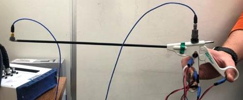
2.3Analysis TheexperimentalsetupincludedanEndoDissectlaparoscopicsurgeryinstrument(Medtronicplc,Dublin,Ireland),a2.7mm vibratingmotor,fiveFlexiForce™sensors(Tekscan,Inc., Boston,MA),andtwopiezoelectricaccelerometers(Handle: J352C34,Tip:352C42,PCBPiezotronics,Inc.,Depew,NY).TheFlexiForce™sensorswerecalibratedusingahandheld forcegauge(DFG35-10,OmegaEngineering,Norwalk,CT).Dataacquisitionfortheforcesensorsandaccelerometerswas madeusingaNationalInstrumentsUSB-6251andMATLAB2018B.Figure 2.1 showsanimageoftheEndoDissectwith theforcesensors,vibratingmotor,andaccelerometersaffixedtotheinstrument.Theforcesensorswereattachedatcontact pointsalongtheinstrumenthandletomeasurethecontactforceofeachfinger.Anelectronicallycontrolledresistancebox (ohmSOURCEOS-250,IETLabs,Inc.,Westbury,NY)wasconnectedinserieswiththevibratingmotorandwasusedto controlthemotorfrequency.
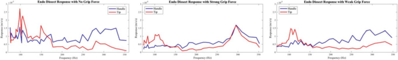
Theinstrumentamplituderesponsewasmeasuredatboththehandleandtipundervaryingmotorfrequenciesandgrip pressuresfor10sateachiteration.FrequencyresponsesatthetipandhandlewerethenextractedfromtheFastFourier Transformoftheaccelerometerdata,alongwiththevoltageamplitudeatthosefrequencies.Finally,theamplituderesponses ofthetipandhandlewerecompared(Fig. 2.2)todeterminethefrequencyrangeswhereasmallresponseoccursatthetip, butasomewhatlargerresponseoccursatthehandle,i.e.toensurevibrotactilefeedback.
InobservingFig. 2.2,itcanbeseenthatforfrequenciesgreaterthan175Hztheamplitudeatthetipislowerthanthat ofthehandle.Thisfindingindicatesthatforlaparoscopicsurgicalinstrumentswithahapticinterface, thevibratorymotor shouldrotateatthesehigherfrequenciestoensurethatthe tipoftheinstrumentisstaticwhilethehandleisvibrating.
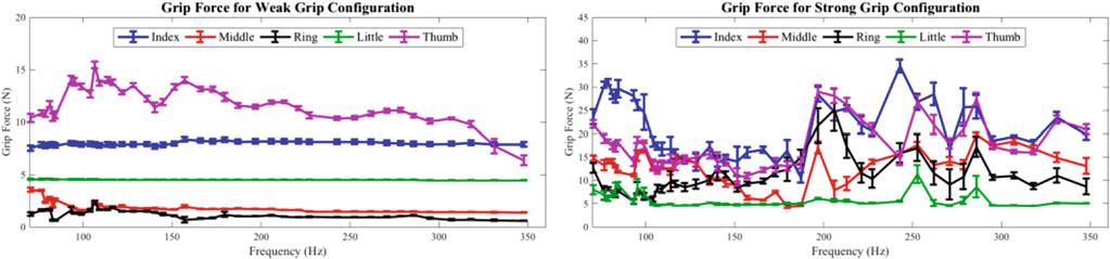
Figure 2.3 illustratesthegrippingforcesforeachofthecontactpointsontheinstrumenthandleasafunctionofthemotor frequency.Theweakgripconfigurationresultedinamoreconsistentgrippingforceforeachfinger,whilethestronggrip configurationwasmoreunpredictable.Furthertestsarewarrantedfortestinggrippingpressuresofsurgeonstodetermine thedistributionofcontactpressurefromeachfingeralongtheinstrumenthandleandhowvarying grippingstylesimpactthe frequencyresponseattheinstrumenttipandhandle.PreliminaryresultsfromFigs. 2.2 and 2.3 indicatethatthetipandhandle
Fig.2.1 ExperimentalsetupoftheEndoDissectwithfiveFlexiForce™A101sensorsattachedatthehandle,avibratingmotorattachedatthe handle,andtwoPCBPiezotronicsaccelerometersattachedatthehandleandtip
2VibrationTestingofLaparoscopicSurgicalInstrumentsUnderVaryingGripPressures11
Fig.2.2 Normalizedamplituderesponsevs.vibrationmotorfrequencyplotsfortheinstrumenttipandhandleresponseatvaryinggrippressures. Responseisnormalizedbythesquaredfrequencytoensureconstantamplitudeacrossfrequencysweeps
Fig.2.3 Averagecontactforcefromeachfingerfortheweakandstronggriptrialsacrossallfrequenciestested.Errorbarsindicatestandard deviations responsesarecomparableregardlessofgrippressure;however,asindicatednear285Hzinthestronggripconfiguration,a larger-amplituderesponsemaybeafactortoconsiderwhenholdingtheinstrumentwithanincreasedgripforce.
2.4Conclusion Thisstudyinvolvedvibrationtestsonalaparoscopicsurgicalinstrumentheldatvaryinggrippressuresandexcitedbya motorwitharotatingmassimbalance.Resultsfromthisstudyindicatethatlowerfrequenciesshouldbeavoidedwhen providingexcitationtolaparoscopicinstrumentstoensurethathandleresponseexceed stipresponse,leadingtoanincreasein instrumentcontrolandprovidingandecreasedrisktopatients.Furtherworkisbeingcompletedtotestexcitationwaveforms withtheplantotrainaneuralnetworktoalterthemotorfrequencyinreal-timeusinggrippressure.Additionally,wewillbe testingthegripsofmultiplesurgeonsattodeterminetheoptimalgripconfigurationandmotorfrequencycombination.
Acknowledgements WewouldliketoacknowledgetheDepartmentofMechanicalEngineering&MaterialsScienceatDukeUniversityandthe DepartmentofSurgeryatDukeUniversityMedicalCenterforprovidingthenecessaryfundingtosupportthisresearch.
References
1.Berguer,R.,Forkey,D.,Smith,W.:Ergonomicproblemsassociatedwithlaparoscopicsurgery.Surg.Endosc. 13(5),466–468(1999)
2.Koehn,J.K.,Kuchenbecker,K.J.:Surgeonsandnon-surgeonspreferhapticfeedbackofinstrumentvibrationsduringroboticsurgery.Surg. Endosc. 29(10),2970–2983(2015)
3.Panait,L.,Akkary,E.,Bell,R.L.,Roberts,K.E.,Dudrick,S.J.,Duffy,A.J.:Theroleofhapticfeedbackinlaparoscopicsimulationtraining.J. Surg.Res. 156(2),312–316(2009)
4.Basdogan,C.,Ho,C.H.,Srinivasan,M.A.:Virtualenvironmentsformedicaltraining:graphicalandhapticsimulationoflaparoscopiccommon bileductexploration.IEEE/ASMETrans.Mechatronics. 6(3),269–285(2001)
5.Wottawa,C.R.,Cohen,J.R.,Fan,R.E.,Bisley,J.W.,Culjat,M.O.,Grundfest,W.S.,Dutson,E.P.:Theroleof tactilefeedbackingripforceduring laparoscopictrainingtasks.Surg.Endosc. 27(4),1111–1118(2013)
JamesP.Winkel,VicenteJ.Suárez,andJamesC.Akers
Abstract Vibrationtestingspaceflighthardwareisavital,buttimeconsumingandexpensiveendeavor.Traditionallymodal testsareperformedatthecomponent,subassembly,orsystemlevel,preferablyfree-freewithmassloadedinterfacesor fixedbaseonaseismicmasstoidentifythefundamentalstructuraldynamic(modal)characteristics.Vibrationtestsare thentraditionallyperformedonsingle-axissliptablesatqualificationlevelsthatenvelopethemaximumpredictedflight environmentplus3dBandworkmanshipinordertoverifythe spaceflighthardwarecansurviveitsflightenvironment.These twotestscurrentlyrequiretwosignificantlydifferenttestsetups,facilities,andultimatelyreconfigurationofthespaceflight hardware.Thevisionofthisresearchistoshowhowtraditionalfixed-basemodaltestingcanbeaccomplishedusingvibration qualificationtestingfacilities,whichnotonlystreamlinestestingandreducestestcosts,butalsoopensupthepossibility ofperformingmodaltestingtountraditionallyhighexcitationlevelsthatprovidefortest-correlatedfiniteelementmodels tobemorerepresentativeofthespaceflighthardware’sresponseinaflightenvironment.Thispaperdocumentsthefirst stepstowardsthisvision,whichisthecomparisonofmodalparametersidentifiedfromatraditionalfixed-basedmodal testperformedonamodalfloorandthoseobtainedbyutilizingafixedbasedcorrectionmethodwithalargesingle-axis electrodynamicshakerdrivingasliptablesupplementedwithadditionalsmall portableshakersdrivingonthesliptableand testarticle.Toshowrobustnessofthisapproach,thetestarticlechosenisasimplelinearweldment,whosemass,size,and modalparameterscouplewellwiththedynamicsoftheshaker/sliptable.Thispaperwillshowthatalldynamicsduetothe shaker/sliptableweresuccessfullyremovedresultingintruefixed-basemodalparameters,includingmodaldamping,being successfullyextractedfromatraditionalstylebase-shakevibrationtestsetup.
Keywords Modaltesting·Pretestanalysis·Modelupdating·Base-shake·Environmentaltesting·Fixedbase
3.1Introduction Testingspaceflighthardwareisavital,buttimeconsumingandexpensiveendeavor.Traditionaldynamictestmethods presentlyrequiretwoseparatetests;thefirst,amodaltestperformedonaseismicmass,andthesecond,aflightlevel verificationtestperformedonashakertable.Thevisionofthisresearchistocombinetwoseparatestructuraldynamic testsrequiredforspacehardwareverificationintoone,whichwouldallowperformingmodaltestingtountraditionallyhigh excitationlevelsthatcouldapproachflightlevels.
Severaldifferentmethodshavebeenproposedtoextractfixedbasemodesfromstructuresmountedonshaketables[1–9]. AuthorsofthispaperwereabletobeinvolvedwithutilizingoneofthesemethodsdevelopedbyATAEngineering,which utilizestheshaketableaccelerationsasreferenceswhencalculatingtheFrequencyResponseFunctions(FRFs)[8, 9].Itis theintentofthisresearchtostartwherethesetwopapers leftoffandfurtheradvanceutilizationofthesemethods.
Currentlyonlythefirststageofamulti-phaseresearchefforthasbeencompleted.Thispaperdiscussesthetestsetup,trade studiesperformedpriortothetestingontheshakertable,describingthechallengesandlessonslearnedthusfar,andfinally disclosingtheplanforcompletingtheremainingtwophasesoftheresearcheffort.Inthenextphase,theprimaryobjective willbetoprocessallthedatacollectedinthefirstphaseandformulateatestplanthatincorporatesanynecessarychanges.In thethirdandfinalphase,theplanwillbetocarryouthighlevelvibrationtestingandextractingfixedbasedmodalparameters fromthissametest.
J.P.Winkel( )·V.J.Suárez·J.C.Akers
NASAGlennResearchCenter,Cleveland,OH,USA
e-mail: james.winkel@nasa.gov
©SocietyforExperimentalMechanics,Inc.2020
M.L.Mains,B.J.Dilworth(eds.), TopicsinModalAnalysis&Testing,Volume8,ConferenceProceedingsoftheSocietyfor ExperimentalMechanicsSeries, https://doi.org/10.1007/978-3-030-12684-1_3
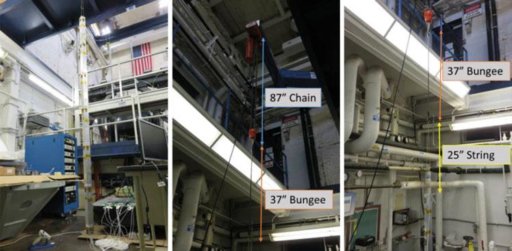
3.2SimpleBeamPathfinderStudy Asapathfindertoverifythatthemethodology ofusingaccelerationsasreferencesto removebasemotionwasbeingproperly implemented,asimplefree-freebeamwasused[10].Thesetupofthissimplefree-freebeaminvolveda2 square6061-T6 aluminumhollowrectangularcross-sectionbeamthatwas87 longandhadawallthicknessof0.125 thick.Asshownin Fig. 3.1,thebeamwassuspendedfroma1tonoverheadcranehangingover12ft.abovethetopofthebeam.Athinnylon stringwasuseddirectlytiedtothetopofthebeam.Inbetweenthestringandthechainofthehoist,arubberbungee cordwasaddedtoisolateanymodesfromthecraneinfluencingthebeamaswellaslowertherigidbodysuspension modesofthebeamtofrequenciesmuchlowerthantheflexiblebodymodefrequenciestosimulateafree-freeboundary condition.
Thebeamwasdividedintosixequalsectionsandsevenuniaxialaccelerometerswereplacedalongthebeamineachofthe twolateralbeamdirections.Asingleuniaxialaccelerometerwasplacedatthetopof thebeamorientedintheaxialdirection tobeabletomeasuremotionalongthebeamsaxialdirection.Thistotaledupto15channelsofaccelerometerdataforthe test.Asmallimpacthammerwithawhitevinyltipwasutilizedfortheexcitation.Atotaloftenimpactswerecollectedat eachofthe15accelerometermeasurementlocations.
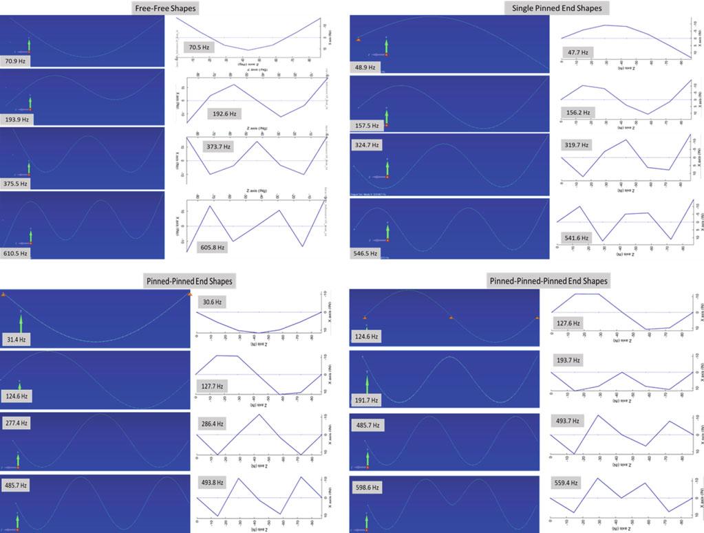
Themethodwasexercisedtoverifythatthemodalparametersofthissimplebeamwiththefollowingthreerestrained boundaryconditions:pinnedat oneend,pinnedatbothends,andpinnedattheendsaswellasinthemiddle,couldbe extractedfromitsfree-freemodalhammersurvey.Afiniteelementmodel(FEM)wasgeneratedutilizing2Dbeamelements withatotalfourboundaryconditions,thefree-freeboundaryconditionsofthetestandthethreerestrainedboundary conditions.ThefirstfourFEMmodalfrequenciesandmode shapesofthefourboundaryconditionswerecomputedand comparedtothemodesextractedusingthe fixed-basemethodandareshowninFig. 3.2
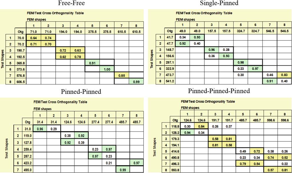
Timehistorieswerepostprocessedintofrequencyresponsefunctions(FRF)byconcatenatingtheimpacthammerdata intoonelongtimehistoryfiledependinguponthespecificlocationsneededtoextractthedesiredboundarycondition.For example,insimulatingtheboundaryconditionofthebeambeingpinnedatbothends,theimpacttimehistoriesfortheX (lateral)directionsatbothendlocationwereconcatenatedtogether.Thenthetimehistorieswerepostprocessedusingdrive pointaccelerationsatthoseimpactlocationsasreferences.TheHvFRFmethodwasutilizedduetothefactthatthenoise levelonthereferenceaccelerometerandresponseaccelerometerwasequalinmagnitude.ComparisonsoftheFEMand extractedfixed-basefrequenciesandavisualinspectionoftheFEMandextractedfixed-basemodeshapeswasperformed andareshowninFig. 3.2.Figure 3.3 illustratesthecrossorthogonalitycomparisonbetweentheFEMandtestresultsfor thesedifferentboundaryconditions.Thisstudyverifiedthatafixed-basecorrectiontechnique,inthisspecificcaseusingdrive pointaccelerometersasreferences,couldbeusedsomewhateffectivelytoextractmodalparametersfordifferentboundary conditionsfromafree-freemodaltest.Itwasdefinitelymoredifficulttoextractcleanmodesshapeswhentheboundary conditionsthetestdatawasbeingcorrectedtobecamemorecomplicated.Thus,whentryingtosimulatethepinned-pinnedpinnedcondition,whilethedeformationshapesandfrequenciesappearedtobecorrect,thecross-orthogonalitywasnotas clean.Moreworkisplannedtobedoneusingthisdatatohelpmakemoresignificantconclusions.Itisthehopethatpriorto usinganyotherfixedbasedcorrectiontechniquesontheshakersliptable,thesetechniquescanfirstbeappliedtothissimple free-freebeamdata.
Fig.3.1 Simplebeampathfindersetup
Fig.3.2 Simplebeampathfinderfixedbasedcorrectionmodeshapeandfrequencycomparison
Therewereafewchallengesencounteredwiththesetupofthispathfinderstudythatifitwereredonewouldbeavoided. Thetestarticlehadasymmetricsquarecross-sectionmeaningthatthereweretwolateralbendingmodesateachresonant frequency,whichwerealignedwiththeaxesofthecross-sectionandthereforeoccurringinorthogonalplanestoeachother. Thecloselyspacedandhighlysimilarmodeshapesmadeitmuchmoredifficulttoextractthemodescleanly.Thesecond wasthatrunningalltheaccelerometercablestapeddownthelengthofthebeamcreatedasignificantamountofmassloading andadditionaldamping.Thisstudyisfarfrombeingfullycompletedandthehopeistospendmoretimewiththisdatagoing forward.
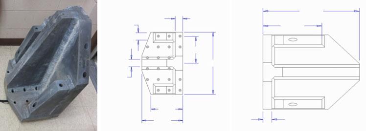
3.3TestArticleSelection Forthefirststageofthisresearch,developmentofanappropriatetestarticlealongwithalltheinfrastructureneededto performthemodaltestingwasthefirststep.Initially,itwasplannedthatatestarticlewouldbedesignedandfabricatedthat wouldmeetthefollowingrequirements:simpledesignandfabrication,behavelinearly,havesufficientweighttoinfluence thecurrentshakertabledynamics,andhaveitsfundamentallowestfrequencymodesinthesamefrequencyrangeasmost aerospacestructures.Shortlyintotheprocess,itbecameclearthatmeetingalltheserequirementswouldbecostprohibitive andwouldexceedthefirststagescheduleconstraints.As acompromise,anexistingmagnesiumbookendusedinthe dynamicslabwaschosenbecauseitwouldmeetthefirstthreerequirements.However,unfortunatelyitslowestfundamental
Fig.3.3 Simplebeampathfinderfixedbasedcorrectioncross-orthogonalitycomparison
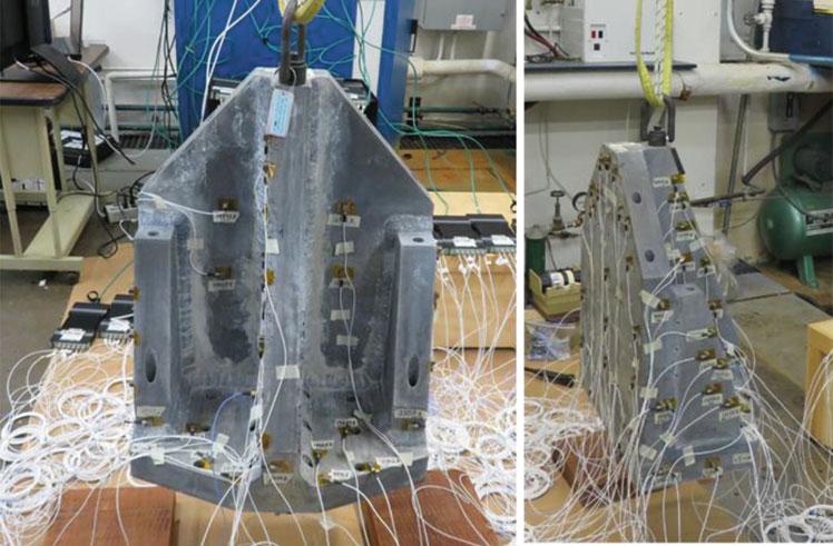
Fig.3.4 Selectedtestarticle
modesaresignificantlyhigherinfrequencythantypicalaerospacetestarticles.Atthetimeitwasfeltthatthislimitation wouldnotbeanissueforthefirststageofthisresearcheffort.
Themagnesiumbookendweighed217lbandwasexpectedtobehaveextremelylinearsinceitwasafullywelded magnesiumstructure.Thebookendutilized 3/8in.diameterfastenersina4in. × 4in.squareholepatterntoholditdownto thefloor.MoredetailedinformationonthearticlecanbeseeninFig. 3.4
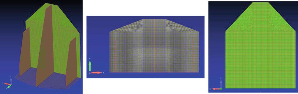
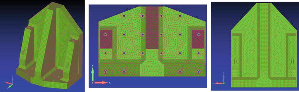
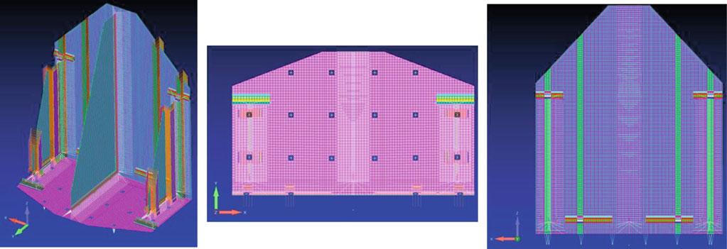
3.4FEMConstructionandSensorPretestTradeStudy AFEMofthismagnesiumbookendwascreatedtosupportthisresearcheffort.ThreedifferentFEMsofthebookendwere generatedusingthreedifferentmodelingtechniquestraditionallyutilizedinmodelingaerospacestructures.Thefirst,and mostsimple,modellingtechniquewastomodelthebookendusing2Dshellelementsovertheentirebookend,whichis typicallydoneinaerospaceloadsFEMs,andisshowninFig. 3.5 andwillbereferredtothroughoutthispaperastheSimple
2DShellFEM.TheadvantagesofthistypeofFEMareitisthesimplestFEMtogenerate,analyze,modify,andithasthe shortestsolutionruntimes.Thedisadvantageofthismodelingtechniqueisthatsimplefeaturessuchasholesandweldsare nottakenintoaccountandthereisalotofduplicationofmassatthejoints,whichwasespeciallythecaseduetotheextreme thicknessoftheplates.
ThesecondmodellingtechniqueutilizedwastoautomeshtheCADrepresentationofthebookendusing3Dsolid tetrahedralelements,whichhastheadvantagethatveryfinedetailcanbeaccuratelycaptured.Theobviousdisadvantages ofthistechniqueisthatsolutionruntimesaresignificantlylongerandtryingtomodifyortroubleshoottheFEMcanbe extremelycumbersomegiventhenumberofelementsandnodesthatareinternaltotheoutersurfaceandnoteasilysorted out.ThebookendFEMutilizingthissecondmodellingtechniqueisshowninFig. 3.6 andwillbereferredtoastheSolid3D FEM.
Thefinalmodellingtechniqueusedisahybridapproachwherethestartingpointwasthesimple2DshellFEMandthen makingmodificationstoeliminatetheoverlappingelementsatjointsandaddinginmoredetailtocapturedetailssuchas holesandwelds.ElementoffsetsandRBE2spiderelementsareutilizedthemakethisaddeddetailpossible.Theadvantages ofthismodelingtechniqueisitallowsfortheincreasedaccuracyofthemassdistributionandstiffnesschangeswithoutgoing tothefullextremeofsolidelements.However,thedisadvantageisitisthemostdifficultandtimeconsumingFEMtocreate. ThebookendFEMutilizingthisthirdmodellingtechniqueisshowninFig. 3.7 andwillbereferredtothroughoutthispaper astheComplex2DShellFEM.
Atthispoint,thereadermaybewonderingwhythreedifferentFEMswerecreatedforthisresearch.Itwasdoneasa sidestudytoallowtestengineerstoabilitytoinvestigatewhichfiniteelementmodelingtechniquewouldmostcloselymatch therealdynamicsofthebookend.Intheprocessoffindingouttheanswertothis,testengineerscouldalsolookintowhich FEMmodelingtechniquewouldbethemostefficienttoutilizeinmodalpretestanalyseswhicharedonetoseehowmany accelerometersarerequiredtoindependentlycapturethetargetmodes.Modalpretestanalysiswasperformedutilizinga customizedsetofMATLAB-basedtestDOFselectiontoolsthatdrawextensivelyuponATAEngineering’sIMAT® software
Fig.3.5 Simple2DshellFEM
Fig.3.6 Solid3DFEM
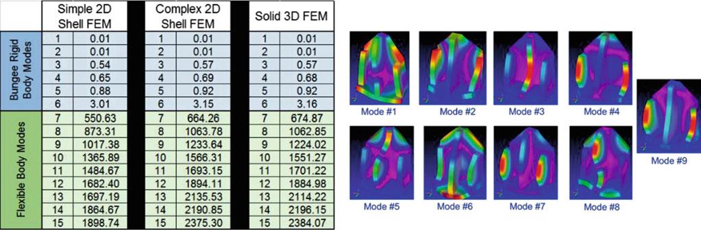
FEMmodalfrequenciesandshapeprofiles
packages.AsimpleCBUSHspringwasattachedtothetopofthebookendrepresentingthetestverifiedaxialstiffnessofa bungeecordthatwouldbeusedtoholdthebookendsuspendedinthesubsequentmodalsurvey.Thefirstnineelasticbody modesforeachFEM(i.e.thesixrigidbodysuspensionmodeswereexcluded)wereusedastargetmodesinthesepretest analyses(Fig. 3.8).
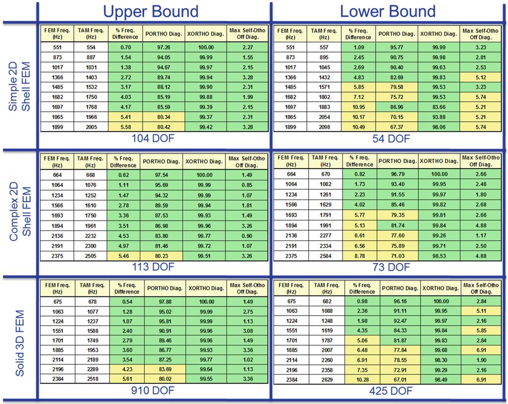
Aninitialset34testDOFwasutilizedthepretestanalysis ofeachFEM.Thissetwasbaseduponengineeringjudgement togivethepretestanalysisagoodstartingpointforcapturingtheshapeandmassdistributionofthetargetmodeset.The IterativeResidualKineticEnergy(IRKE)wasutilizedtoidentifyadditionaltestDOFresultinginatotalof2500testDOF. ThenadownselectionalgorithmcreatedbyATAengineeringwasutilizedtoincrementallyremovetestDOFtoachievea minimaltestDOFsetthatmetthefollowingcriteria(numberedbydesignatedimportance):
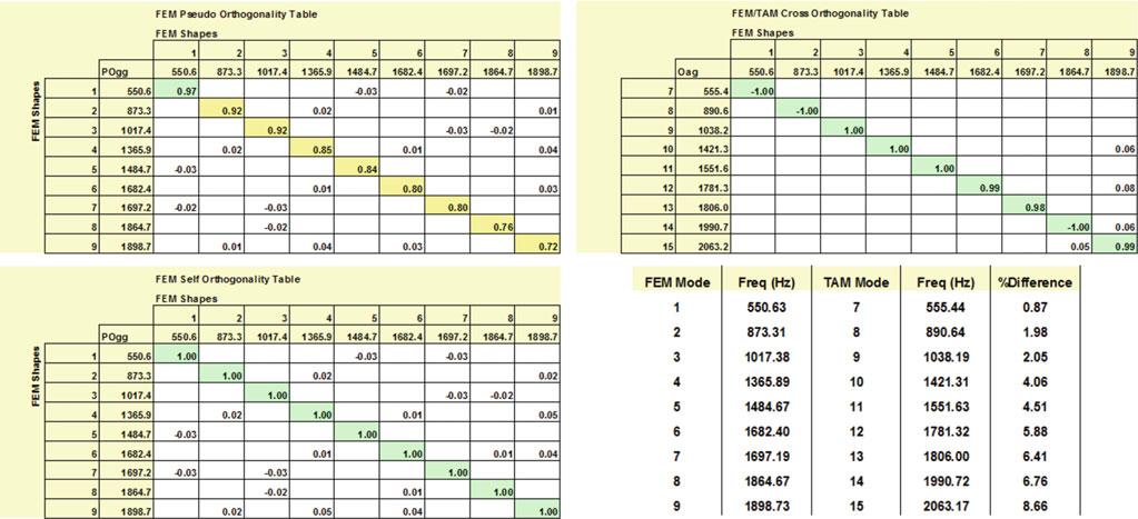
1.<5%frequencydifferencebetweenTAMandFEMfortargetmodes
2.<5%onoffdiagonalofthe Self-OrthogonalityMatrices
3.>90%onthediagonalvaluesand<10%onoffdiagonaloftheCross-OrthogonalityMatrices
4.>80%onthediagonalvaluesPsuedo-OrthogonalityMatrices(Usedtoestablishupperboundonly)
ThesummarytablesforeachofthepretestanalysisofeachFEMisshownTable 3.1.Therearetwotablesshownfor eachFEMwiththeUpperBoundbeingwherethePseudo-OrthogonalitycriteriaisnolongermetandtheLowerBound beingwheretheSelf-Orthogonalitycriteriaisnolongermet.TheoptimalsetoftestDOFisbetweenthesetwoboundsand isusuallymuchclosertotheLowerBound.
Thisstudyshowsthattheuseof3Dtetrahedralsolidelementsisnotconducivetothistypeofsensorselectionapproach.It shouldbemadeclearthatfortheSolid3DFEM,theonlytestDOFthecomputerwasallowedtoselectwereontheexternal surface.Thiswasdoneduetothefactthataccelerometerscannotbe placedinsidethetestarticle.Itisunderstoodthata2D
Fig.3.7 Complex2DshellFEM
Fig.3.8
Table3.1 FEMpretestanalysiscomparisons
ShellelementsexhibitsimilarissuesinthatthetestDOFselectedaretechnicallyonthecenterlineofeachsurfaceandcan alsonotbeselected,however,allthemassoftheFEMisdistributedtothosesamenodesina2Dshellelement.Withasolid 3Delement,themassisdistributedinamuchfinerfashionandmuchmoredifficulttocaptureusinglimitedinstrumentation. BoththeSimpleandcomplex2DshellFEMsdoareasonablejobofselectinganoptimizedsetoftestDOF,withtheSimple 2DShellFEMdoingaslightlybetterjob.
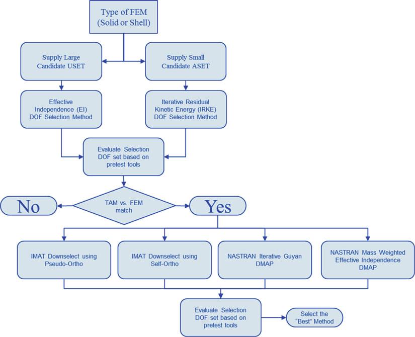
Afterseeingtheseresults,itwasquestionedaboutwhethertheappropriateDOFselectionmethodwasbeingutilizedor not.ThereforeasimpleplantoevaluateotherDOFselectionprocesseswascreatedandcarriedout.Theflowchartshownin Fig. 3.9 describesthisprocess.
AfterfinishingthisprocessonallthreeFEMs,theresultsclearlyshowedthattheIRKEselectionmethodoutperformed theEffectiveIndependenceselectionmethod.Theotherfindingwasthatnomatterthemethodused,thesolid3DFEM alwaysrequiredmuchhigherDOFcountstoachieveresultswithinthestatedguidelinesabove.Thisstudyservedasagood confirmationthatthestandardwaytheengineershadbeendoingpretestsensorsselectionsforpastmodaltestwasindeedthe mostefficientwaytodothem.
ThefinalstepwastoutilizetheSimple2DShellFEM,whichinthestudiesaboveshowedthebestabilitytopredictan optimalsensorset,tofinalizethenumberandlocationofthesensors.Asetof75DOFwasselectedwhichmettheoverall majorityofthepretestguidelinesweremetandcanbeseenindetailinFig. 3.10
Fig.3.9 Pretestanalysismethodologyevaluationflowchart
Simple2DshellFEMfinalpretestresults
Fig.3.10
3.5BookendFree-FreeModalTestandModelCorrelation ThetestarticlewassuspendedfromasoftbungeecorddisplayedinFig. 3.11 thatresultedinabouncemodeat3Hzand alloftheremainingsuspensionmodes(e.g.firstandsecond pendulummodes)below3Hzsothatallsuspensionmodesare morethantwoordersofmagnitudebelowthefirstflexiblebodymode.
Animpactmalletwithahardblackvinyltipwasutilizedtoexcitethestructure.Thistipwasabletoproducehighquality excitationwithgoodcoherenceupto1400HzshowninFig. 3.12.However,theFRFsseemtoholdtheirqualityof2300Hz. Becausethisisnotanactualtestofflighthardware,itwasconsideredacceptabletoignoretheguidelinesinthisspecificcase andusethemodalparametersextractedupto2300Hz.
Nowthattestresultshadbeenobtained,itwaspossibletodeterminetheanswerstothenewfewquestionsaboutwhich FEMconstructiontechniquewouldbestpredicttheactualtestresultswithoutmodelupdatingandtheFEMengineersshould continuetoutilizegoingforwardintheresearch.
1.Whichmodelisthemostaccuratecorrelationwithoutanymodelupdating?
2.IsmodelinginsomuchdetailwiththeComplex2DShellFEMrequiredorwhatsubsetofmodelingfeaturesarereally necessary?
3.Whichmodelwouldbethe“best”touse?“Best”meaninga goodbalanceofbothaccuracyofthehardwarewhilealso beinguserfriendly.
TheSolid3DFEMwasnotabletobeincludedfullyinthispartofthestudybecausethereducedmassandstiffness matricesgeneratedusingthechosensetofDOFwassoinsufficient,itcorruptedthecross-orthogonalitymatrices.However, thefrequencycomparisonfortheSolid3D FEMwasgeneratedforreferenceinFig. 3.13
OnecanseetheresultsinFig. 3.13 thattheComplex2DShellFEMdoesthebestjobpredictingtherealtestresultswhen consideringitcanbebetterutilizedinapretestsensoreffort.TheSolid3DFEM,asexpected,doesaverydecentjobin predictingtheresults.Itonlyslightlyoverpredictsthestiffnessofthetestarticle.TheSimple2DShellFEMunderpredicts thestiffnessofthemodelandthusissimulatingatestarticlethatistooflexible.
Inanormalmodaltestingeffort,testengineerswouldprobablynotseeaneedtoupdateanythingwitheithertheComplex 2DShellFEMortheSolid3DFEM.However,inthisresearcheffortitwasdesiredtoknowwhatfeaturesintheComplex 2DShellFEMwerereallynecessary.BystartingwiththeComplex2DShellFEMandslowlyremovingonecomplicated featureafteranother,itwasrevealedthatreallyonlyonecomplexfeature,thespiderRBE2elementsconnectingtheplates together,isnecessaryinmakingany2DshellFEMmostaccuratelysimulaterealtestresults.InFig. 3.14,onecanobserve thecomparisonbetweenthestartingComplex2DShellFEMtothemuchsimplercorrelatedversion.
Another random document with no related content on Scribd:
in place. Concave cylinders are then employed in quarters until the final results of +1.D. spherical, combined with -1.D. cylinder axis 180° is secured. This necessitates the change of but four cylindrical lenses as shown in routine “A” as follows:
ROUTINE “A” ROUTINE “B” (Made with minus cylinder) (Made with plus cylinder) Sph. +1.D. Cyl. Axis Sph. +1.D. Cyl. Axis
Step 1 +1.D. = -.25 ax. 180° equal to +.75 = +.25 ax. 90°
Step 2 +1.D. = -.50 ax. 180° equal to +.50 = +.50 ax. 90°
Step 3 +1.D. = -.75 ax. 180° equal to +.25 = +.75 ax. 90°
Step 4 +1.D. = -1 ax. 180° equal to 0 +1 ax. 90°
In brief the method of using minus cylinders exclusively in an examination, as explained in routine “A”, necessitates the change of the cylinder lenses only after the strongest plus sphere is secured.
On the other hand, notwithstanding innumerable other methods where plus cylinders are used, routine “B” shows that the best spherical lens strength the patient will accept, is also first determined. Then both spheres and cylinders are changed in their regular order by gradually building up in routine, by increasing plus cylinder and next decreasing sphere, a quarter diopter each time, until the final result is secured.
While it is conceded that both routine “A” and “B” are of themselves simplified methods, by comparing routine “A” where minus cylinders are used with routine “B” where plus cylinders are used in their corresponding steps, the refractionist will note by comparison that one is the exact equivalent and transposition of the other. Where plus cylinders are employed, eight lens changes are made before final results are secured; while but four lens changes are necessary where minus cylinders are used.
The refractionist should also note by comparison that the use of minus cylinders reduces focus of the plus sphere, but only in the meridian of the axis. It has not made the patient myopic. Furthermore, a plus cylinder will bring the focal rays forward, while minus cylinders throw them backward toward the retina.
This is but another reason for the exclusive use of minus cylinders in refraction.
The method of using minus cylinders exclusively in an examination, necessitates the change of the cylinder lenses only. On the other hand, the method of using plus cylinders makes it necessary to change spheres and cylinders in routine.
In brief, since using the minus cylinder is merely a matter of mathematical optics, their use even in a trial-case examination is strongly urged.
The maximum value of the Ski-optometer is fully realized only when the advantages of using minus cylinders exclusively in every examination is clearly understood.
C������� A�������� N�� R������� With the Ski-optometer, when the examination is completed, the sum-total of final results—whether spherical, cylinder, axis, or all combined—are automatically indicated or registered ready to write the prescription. Until then, the foci of the various lenses that may be employed are of no importance.
In short, in using the Ski-optometer, it is not necessary to constantly watch the registrations during examinations. The automatic operation of the instrument is an exclusive feature, so that the refractionist should unhesitatingly employ it. Hence, by eliminating the perpetual watch on the lenses in use, the refractionist is enabled to give his undivided attention to the patient rather than to the trial lenses.
Where a special dark-room is used for skioscopic work, an additional wall bracket or floor stand will necessitate only the removal of the instrument itself. This enables the refractionist to use the Ski-optometer for subjective or objective work, without disturbing the patient’s correction.
C������ IV IMPORTANT POINTS IN CONNECTION WITH THE USE OF THE SKI-OPTOMETER T�� Ski-optometer is equipped with an adjustable head-rest, permitting its lenses to be brought as close as possible to the eye without touching the patient’s lashes, a matter of importance in every examination.
Fig. 11—The nasal lines of the Skioptometer fit the contour of face with mask-like perfection, patient remaining in comfortable position.
E���������� �� T����-F���� D��������� Where the Ski-optometer is correctly fitted to the face, the patient invariably remains in a comfortable position (Fig. 11). The instrument is shaped to fit the face like a mask, so that even with a pupillary distance of but 50 m/m (that of a child) there still remains, without pinching, ample room for the widest nose of an adult.
Before making an examination, the correct pupillary distance should always be obtained by drawing an imaginary vertical line downward through the center of each eye from the 90° point on the Ski-optometer axis scale. The pupillary distance will then register in millimeters on the scale of measurements for each eye separately. If the Ski-optometer is correctly adjusted, the patient is securely held in position, the cumbersome trial-frame being entirely eliminated.
R������� �� C����������� Illustration on following page (Fig. 11a) shows the reinforced double bearing arms which hold the Ski-optometer lens batteries at two points. This eliminates possibility of the instrument getting out of alignment, and prevents wabbling or loose working parts.
The broad horizontal slides shown in the cut, move in and out independently so that the pupillary distance is obtained for each eye separately by turning the pinioned handle on either side of the instrument. The scale denotes in millimeters the P.D. from the median line of the nose outward, the total of both scales being the patient’s pupillary distance.
Fig. 11a also serves to show the staunch construction of the base of the Ski-optometer.
Fig. 11a Showing staunch construction of Ski-optometer base.
H�� �� P���� ��� S��-��������� �� P������� The patient should be placed in a comfortable position with “chin up,” as though looking at a distant object. The instrument should then be raised or lowered by the adjustable ratchet wheel of the bracket. The wall bracket gives best results when suspended from the wall, back of the patient, as shown on page 135. This bracket should be placed about ten inches above the head of the average patient. When the Ski-optometer is placed in position for use, its lower edge will barely touch the patient’s cheeks. It is sometimes advisable to request the patient to lightly press toward the face the horizontal bar supporting the instrument. Particularly good results are secured where a chair with a head-rest is employed in conjunction with the Ski-optometer. (See illustration of Model Refraction Room, Page 112).
C������� ��� L����� The time-waste of perpetually cleaning lenses is overcome where the Ski-optometer is employed. For the convenience of the operator and protection of Ski-optometer lenses, the latter are concealed in a dust-proof cell, overcoming all dust and finger-print annoyances. When not in use, the instrument should be covered with the standardized hood forming part of the equipment.
The instrument should not be taken apart under any circumstances. To clean its lenses, not a single screw need be removed, as the lenses of each disk may be cleaned individually through the opening of the other disks. These openings are conveniently indicated by the white zeros (Fig. 2). The Ski-optometer contains but eleven spherical and eight cylindrical lenses on each side, so that the actual work of cleaning should not require over ten minutes at the most, cleaning the lenses every other week proving quite sufficient.
A������� A������ �� E���� T��� Loss of refraction is completely eliminated through the use of the Ski-optometer. The most casual examination of the trial-frame or any other instrument shows that the construction necessitates the placing of the spherical lens next to the eye with the cylinder lens outermost—a serious fault wholly overcome in the Ski-optometer.
Not only do the cylindrical lenses of the Ski-optometer set directly next to the patient’s eye, thus overcoming any possible loss of refraction, but the strong spherical lenses of the supplementary disk are set directly next to the cylinder. There is apparently but a hair’s distance between these lenses; the two disks containing the spherical lenses of the Ski-optometer likewise setting close together
In a word, the Ski-optometer’s cylinder lenses set directly next to the patient’s eye, followed by the stronger sphericals, so that the weakest spherical or +.25 (the lens of least importance) sets farthest away. This is 3½ m/m closer than any trial-frame manufactured,
however, and at least 10 m/m closer than any other instrument— another reason for implicitly relying on the Ski-optometer for uniformly accurate results.
B���� �� L��� � L������� Fig. 12—(A. and B.)—This unique, patented split-spring device of screwless construction, securely holds all movable parts. In case of repair, they may be removed with the blade of a knife.
The Ski-optometer is built on the plan of ¹/₁₀₀₀″, insuring absolute rigidity and accuracy and a lifetime of endurance. Particular and detailed attention has been given to the novel means of eliminating screws which either bind, create friction or continually work loose, causing false indications of findings on scales of measurements; hence correct and accurate indications are insured in the Ski-
optometer by means of a split-spring washer construction similar to that of an automobile tire’s detachable rim (Fig. 12).
This patented spring washer construction securely holds the phorometer lenses, the rotary prism and the revolving cylinder lens cells.
Whenever necessary, or in case of repair, these parts may be readily removed with the blade of a knife.
C������ V CONDENSED PROCEDURE FOR MAKING SPHERE AND CYLINDER TEST WITH THE SKI-OPTOMETER N�������������� various methods employed, for both subjective and objective refraction, the following synopsis of the previous chapters will unquestionably prove most valuable to the busy refractionist, enabling him to make error-proof examinations in practically every case without resorting to the transference of trialcase sphere or cylinder lenses. A careful reading of chapters one and two should be made however, so that one may gain an understanding as to how spheres and cylinders are obtained with the Ski-optometer
S��������� D������� T��� 1st—Place Ski-optometer in position, employing spirit level, thus maintaining instrument’s horizontal balance.
2nd—Adjust the pupillary distance for each eye individually, by drawing an imaginary vertical line downward through the center of each eye from the 90° point on the Ski-optometer’s axis scale. The opaque disk should be placed before the patient’s left eye by setting the supplementary disk handle at “shut.”
3rd—The Ski-optometer lens battery before the patient’s right eye should be set at “open” (figure 2), whereupon the first turn of spherical lens battery toward the nasal side places a +6.D sphere in position. This should blur vision of average patient.
4th—It is now only necessary to remember that an outward turn toward temporal side of the instrument increases plus sphere power, while a nasal turn decreases it. Therefore continue to reduce convex spherical lens power until the large letter “E” on the distant test card is clear. Then request patient to read as far down as possible,—a rapid turn of a quarter diopter being readily accomplished with the Ski-optometer (Fig. 4).
5th—In the event of working down to “zero” with spheres, the supplementary disk handle or indicator should next be set at -6.D sphere, while the spherical reel should be turned toward the nasal side—thus building up on minus spheres (Fig. 6). In short, the strongest plus sphere or weakest minus sphere should always be determined before employing cylinders.
6th—With the best spherical lens that the patient will accept left in place, direct attention to the letter E or F in the lowest line of type the patient can see on the distant test letter chart. Then set axis indicator at 180° (Fig. 7).
7th—Next increase concave cylinder power until vision is improved. If vision is not improved after increasing cylinder strength to -.50 axis 180°, merely reverse the axis to 90°. If vision is improved, cylinder lens strength should be increased. If not, it should be decreased (Fig. 8).
8th—Slowly move axis indicator through entire arc of axis, thus locating best possible axis (Fig. 7).
9th—After sphere and cylinder test of right eye has been made, place supplementary disk handle at “shut.” Then repeat procedure in testing left eye.
10th—After completing examination for each eye separately, then, with both of the patient’s eyes open, direct attention to lowest line of type he can see, concentrating on the E or F, simultaneously increasing or decreasing spherical power before both eyes. The refractionist merely recalls that by turning the Ski-optometer’s single reel toward the temporal side, convex spherical power is increased, by turning toward the nasal side for either eye, spherical power is
decreased. Cylinder lens strength may be changed in a like manner before both eyes simultaneously.
11th—After making the distance test, then only is it necessary to copy the result of the examination as recorded by the Ski-optometer.
S��������� R������ T��� Tilt Ski-optometer forward in making reading test. The wide groove in the horizontal bar supporting the instrument, permits it to be slightly tilted.
12th—Place Ski-optometer reading rod in position with card at about 14 inches. Close off one eye. Direct patient’s attention to the name “Benjamin” printed at top of card.
13th—Leave cylinder lens in place. Proceed as in distance test with +6.D sphere, fogging down until the first word “laugh” on the reading card, in line 75M, is perfectly clear, this being slightly smaller than the average newspaper type.
14th—After completion of examination for each eye separately, then with both eyes direct patient’s attention to word “laugh.” Move reading card in or out a few inches either side of 14 inch mark. This will determine any possibility of an over-correction. Then record prescription just as Ski-optometer indicates. For a detailed description of above, as well as for objective testing with the Skioptometer, read chapter three.
C������ VI MUSCULAR IMBALANCE T�� purpose of the present chapter is to acquaint the refractionist with the operation of the Ski-optometer as “a scientific instrument for muscle testing”—the subject being treated as briefly and comprehensively as is practicable.
As the reader progresses in the subject of muscular anomalies, he may carry his work to as high a plane as desired, increasing his professional usefulness to an enviable degree.
Through the use of the Ski-optometer, muscle testing may be accurately accomplished in less time than a description of the operation requires. Furthermore, tedious examinations may be wholly overcome through the discontinuance of the consecutive transference of the various degrees of prisms from the trial-case. In fact, the latter method has long been quite obsolete, owing to the possibility of inaccuracy. The muscle action of the eye is usually quicker than the result sought through the use of trial-case prisms; hence muscle testing with the Ski-optometer is accomplished with far greater rapidity and accuracy, thus making the instrument an invaluable appliance in every examination.
T�� A����� �� P����� Students in refraction—and one may still be a student after years of refracting—are sometimes puzzled as to just what a prism does when placed before an eye. They refer to every available volume and are often confused between ductions and phorias, finally dropping the subject as an unsolvable problem. In view of this fact, it is suggested that the refractionist should read the present volume with the actual instrument before him.
Before proceeding, one should first understand the effect of a prism and what it accomplishes. To determine this, close one eye, looking at some small, fixed object; at the same time, hold a ten degree prism base in before the open eye, noting displacement of the object. This will clearly show that the eye behind the prism turns toward the prism apex.
To carry the experiment further, the following test may be employed on a patient. Covering one eye, direct his attention to a fixed object, placing the ten degree prism before the eye, but far enough away to see the patient’s eye behind it. As the prism is brought in to the line of vision, it will be seen that the eye turns towards the apex of the prism. When the prism is removed, the eye returns to its normal position.
Similar experiments enable the refractionist to make the most practical use of treating phorias and ductions, as well as to comprehend all other technical work.
Fig. 13 An important part of the equipment for muscular work.
T�� P��������� As previously stated, it is practically impossible to accurately diagnose a case of muscular imbalance with trial-case prisms. For this reason the phorometer forms an important part of the equipment for muscle testing in the Ski-optometer, having proven both rapid and accurate. It consists of two five-degree prisms with bases opposite, each reflecting an object toward the apex or thin edge. The patient whose attention is directed to the usual muscle-testing spot of light, will see two spots.
Aside from the instrument itself, and in further explanation of the phorometer’s principle and construction, when two five-degree prisms are placed together so that their bases are directly opposite, they naturally neutralize; when their bases are together, their strength is doubled. Thus while the prisms of the phorometer are rotating, they give prism values from plano to ten degrees, the same being indicated by the pointer on the phorometer’s scale of measurements.
As a guide in dark-room testing, it should be noted that the handle of the phorometer in a vertical position is an indication that the vertical muscles are being tested; if horizontal, the horizontal muscles are undergoing the test.
T�� M����� R�� The Maddox rod (Fig. 14) consists of a number of red or white rods, which cause a corresponding colored streak to be seen by the patient. This rod is placed most conveniently on the instrument, being provided with independent stops for accurately setting the rods at 90 or 180 degree positions. The Maddox rod has proven of valuable assistance in detecting muscular defects, particularly when used in conjunction with the phorometer. Thus employed, it enables the patient to determine when the streak seen with one eye crosses through the muscle-testing spot-light observable by the other eye, as hereafter described.
Fig. 14—The Maddox Rod, a valuable aid in making muscular tests.
P�������� ��� M����� ��� M����� T��� The Ski-optometer should be equipped with two Maddox rods, one red and one white. Their combined use is of the utmost importance since they assist in accurately determining cyclophoria and its degree of tortion as designated on the degree scale, and fully described in a later chapter.
When the Maddox rods are placed in a vertical position, it is an indication that the vertical muscles are being tested; when placed horizontally, the horizontal muscles are being tested. It should be particularly noted that the streaks of light observable through the Maddox rods always appear at right angles to the position in which they lie.
The Ski-optometer should be placed in a comfortable position before the patient’s face with the brow-rest and pupillary distance adjusted to their respective requirements. The instrument should be levelled so that the bubble of the spirit level lies evenly between its two lines, thus insuring horizontal balance. The muscle test light should be employed at an approximate distance of twenty feet on a plane with the patient’s head. Best results in muscle testing are secured through the use of the Woolf ophthalmic bracket, with iris diaphragm chimney and a specially adapted concentrated filament electric lamp (Fig. 9). This gives a brilliant illumination which is particularly essential. The test for error of refraction should be made in the usual manner, using the spherical and cylindrical lenses contained in the Ski-optometer, thus obviating the transference of trial-case lenses and the use of a cumbersome trial-frame. The timesaving thus effected enables the refractionist to include a muscle test in every examination and without tiring the patient—a consideration of the utmost importance.
B�������� ��� M�������� T��� The test for muscular imbalance may be divided in two parts. First, binocular test, or combined muscle test of the two eyes; second, monocular test, or muscle test of each eye separately. The latter does not signify the shutting out of vision or closing off of either eye, since muscular imbalance can only be determined when both eyes are open. These two tests are fully explained in the following chapter.
C������ VII THE BINOCULAR MUSCLE TEST M��� ���� ��� M����� R�� ��� P��������� D�������� the patient’s attention to the usual muscle testing spot of light, the red Maddox rod should be placed in operative position before the eye, with the single white line or indicator on red zero (Fig. 15). The rods now lie in a vertical position.
Fig. 15—The Maddox rods placed vertically denote test for right or left hyperphoria, causing a horizontal streak to be seen by patient.
The pointer of the phorometer should likewise be set on the neutral line of the red scale, causing the handle to point upward (Fig. 16). A distance point of light and a red streak laying in a horizontal position should now be seen by the patient.
Fig. 16—The phorometer handle placed vertically, denotes vertical muscles are undergoing test for right or left hyperphoria —as indicated by “R. H.” or “L. H.”
Instead of memorizing a vast number of rules essential where trial case prisms are employed for testing ocular muscles, the pointer of the phorometer indicates not only the degree on the red scale, but the presence of right hyperphoria (R. H.) or left hyperphoria (L. H.).