Sediment compaction and applications in petroleum geoscience troyee dasgupta - The full ebook with c
Sediment Compaction and Applications in Petroleum Geoscience Troyee Dasgupta
Visit to download the full and correct content document: https://textbookfull.com/product/sediment-compaction-and-applications-in-petroleumgeoscience-troyee-dasgupta/
More products digital (pdf, epub, mobi) instant download maybe you interests ...
Physicochemical Fluid Dynamics in Porous Media Applications in Petroleum Geosciences and Petroleum Engineering Mikhail Panfilov
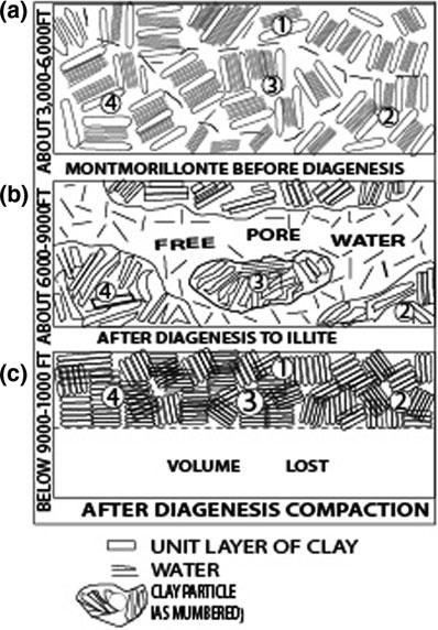
Fig.1.4Differentstagesofcompactioneffectonclay diagenesis. a Claysconsistofboundwateratthetime ofdeposition. b Freewaterincreaseswithburialwith theconsequentreleaseofboundwater. c Freewateris squeezedoutandtheoriginalvolumereduces (Fig.57inRiekeandChilingarian1974)
Fig.4.3AverageporositiescalculatedinNotformationfrom a Sonic(DT)log, b Density(Rhob), c Resistivity (Rt)and d neutronlog.Eachofthepressureregimes areindicatedbydifferentsymbols.Modi fiedafter Hermanrudetal.(1998) 35
Fig.4.4AverageporositiescalculatedinRorFormationfrom a Sonic(DT)log, b Density(Rhob), c Resistivity (Rt)and d neutronlog.Eachofthepressureregimesare indicatedbydifferentsymbols.Modi fiedafter Hermanrudetal.(1998) 35
Fig.4.6Cartoondepictingthewirelineresponsesin a overpressuregeneratedduetocompaction disequilibriumprocess, b overpressuregenerated duetounloadingprocess(Ramdhanetal.2011) ........
Fig.4.9Detectionofunloadingbehaviour a Velocityversus effectivestress,velocityreversalalongwithreduction ineffectivestress. b Densityversuseffectivestress, effectivestressreductionbutdensityremainsconstant (Bowers2001) 39
Fig.4.10Cartoonshowingtheoverpressuretrendspossibly duetounloading. a Fluidpressureversusdepthtrend; b shaleporosityversusdepthtrend; c shaleporosity versuseffectivestress,and d bulkdensityversus velocitytrend
Fig.5.5Pressureversusdepthplots.Themeasuredpressuredata fromthepermeablezoneshavebeenusedandinthe impermeablezonesthepressureshavebeenestimated byindirectmethodsofpressureestimation (mud-weights,D-exponents,connectiongases,etc.). a PressureversusdepthplotintheCentralgrabenarea whichshowsthenormallypressuredPaleocene sandstonesandbeneaththatthereisnormallypressured chalkgroup.Thereisrapidchangeintheprofi lewith increaseintheporepressurefrom f to g andthehighest atthepre-Cretaceousstructureinthe h b Pressure profileofEkofi skField.Thechalkgroup(c, d)is moderatelyoverpressured(Holm1998)
Fig.5.6Pressureprofilesof a Ekofiskarea b Northseaarea’s Zechsteinevaporatesection(Rehm1972) .............
Fig.5.9 a TectonicmapoftheItalianAdriaticarea. b Pressure profileofawellintheItalianAdriaticarea.Inthezones B&Cthepressurevaluesarefarbeyondthenormal pressurevalues. c Plotsshowingoverpressured environmentsinAdriaticsea(Rizzi1973) 61
Fig.5.15Figuresshowingabnormalformationpressuresin AustraliaandPapuaNewGuineaarea. a Location ofoverpressuredwells. b Pressureprofileof overpressuredwellsofAustralia. c Pressureprofile ofoverpressuredwellsofPapuaNewGuinea. (Bigelow1994a,b) .............................. 67
Fig.6.1Erosionthicknesscalculationfromcompactiontrend curvederivedfromsonictransittime(Magara1976). a Noerosionandthesurfacetransittimeisequaltothat ofwater. b Uppersurfaceiserodedandthethicknessis theverticaldistancebetweenthepresentsurfaceandthe originalsurface
Fig.6.2Compactiontrendanderosionalthicknessfrom a EmblemState1and b BridgerButteUnit3byHeasler andKharitonova(1996) ........................... 86
Fig.6.3PorosityversusdepthcurvebyBurnsetal.(2005) fordifferentlithologyusingvolumeofshalecutoff. a Sand(vshale <0.01), b Siltstone(0.49vshale <0.51) and c shale(vshale >0.51)alongwiththecurvesby Rowanetal.(2003) 86
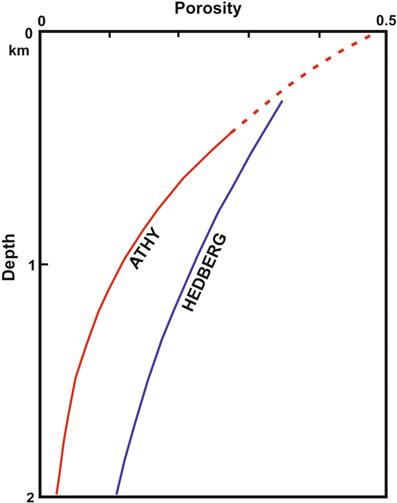
Fig.1.2 a Bulkdensityversusdepthrelationshipfor shalesfromOklahoma(U.S.A). b Porosityversusdepth relationshipforshalesfromOklahoma(U.S.A)(Modified afterFig.14ofRiekeandChilingarian 1974)
Fig.1.4 Differentstagesofcompactioneffectonclay diagenesis. a Claysconsistofboundwateratthetimeof deposition. b Freewaterincreaseswithburialwiththe consequentreleaseofboundwater. c Freewateris squeezedoutandtheoriginalvolumereduces(Fig.57 inRiekeandChilingarian 1974)
PowleyDE(1993)Shalecompactionanditsrelationship to fluidseals.SectionIII,Quarterlyreport,Jan1993–Apr1993,OklahomaStateUniversitytotheGas ResearchInstitute
Another random document with no related content on Scribd:
the liberated, but unconsumed, smoke back into the fire, when it was consumed.
Mr Douglas’s plan was adopted by the Birkenhead Railway He combined the use of an inclined fire-grate of large area, and a baffleplate. In January, 1858, when first introduced, the deflector was fixed to the inner side of the fire-door, but in June of the same year an underhung fire-door and movable baffle-plate were employed. These afterwards gave place to a plain inverted scoop, to project the air right on to the fire.
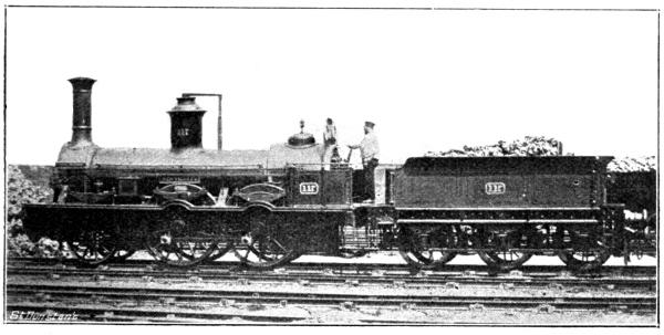
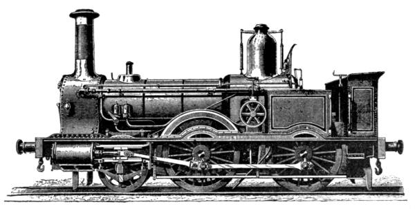
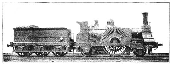
F��. 78.—“NUNTHORPE,” A STOCKTON AND DARLINGTON RAILWAY PASSENGER ENGINE, BUILT IN 1856
After reading the description of the various plans adopted for the consumption of the smoke, readers will at once observe that each and every designer had the same object in view—viz., to supply a sufficient volume of air to the fire, and mix the air with the unconsumed gases given off by the burning coal, and then to prevent the immediate escape of this gaseous mixture from the firebox. Being retained within the heated fire-box, the temperature of the vapour was raised sufficiently, so that the vapour readily burnt when forced by the steam deflector, or brick arch (according to the system adopted), back on to the incandescent fuel. As stated, the object of
all the inventors was the same, but the methods adopted were different, and these latter (though some systems had advantages that others lacked) were successful in each case; but from the whole could be chosen some that certainly were more noteworthy, both as regards simplicity of application and design, and others that were more successful in attaining the object in view—viz., a consumption of the smoke given off by the coal. In these four years—1855-59— however, the problem of consuming the coal smoke, was successfully accomplished, and the era of the coal-burning locomotive definitely inaugurated.
Fig. 78 is an illustration of the “Nunthorpe,” No. 117 of the Stockton and Darlington Railway. This engine shows a distinct advance in locomotive construction; indeed, it is possible at the present time to see on some lines engines somewhat similar in appearance still at work. She was built by Gilkes, Wilson and Co., in 1856, and was intended for passenger traffic. Four of the six wheels were coupled, these being 5ft. in diameter. The cylinders were inside, 16in. in diameter, and with 19in. stroke. The tender was on six wheels, and the tank capacity was 1,200 gallons. The cost of the engine was £2,550. It will be observed that the weather-board of the “Nunthorpe” afforded very little protection to the driver and fireman, but its inclusion in the design of the engine was a step in the right direction.
F��. 79.—BEATTIE’S 4-COUPLED TANK ENGINE, L. & S.W.R., 1857
In 1857 Beattie designed a handy class of passenger tank engines for the L. and S.W.R. Three were built at first, and named “Nelson,” “Howe,” and “Hood.” They had four coupled wheels, 5ft. diameter, and a small pair of leading wheels. The cylinders, which were outside, were 15in. diameter, the stroke being 20in. These engines are illustrated by Fig. 79. They were good locomotives, and “Hood” and “Howe” continued in work till 1885.
Fairlie is usually given the credit of introducing double locomotives with a centre foot-plate. By reference to Chapter IX., it will be seen that the design was patented by Pearson, of the Bristol and Exeter Railway, as long ago as 1847, and in 1855 a double engine, built by R. Stephenson and Co., was at work on the Giovi incline of the Turin and Genoa Railway The incline in question commences 7¾ miles after leaving Genoa, and is six miles long, the average gradient being 1 in 36. The double locomotive was of the tank type. The wheels were 3ft. 6in. diameter, the cylinders 14in. diameter, and the stroke 22in. The machine actually appears to have been two engines placed fire-box to fire-box, and connected by means of a foot-plate between the two fire-boxes. The combination, with fuel and water, weighed 50 tons. In fine weather a load of 100
tons was hauled up the Giovi bank at 15 miles an hour; in bad weather the load was reduced to 70 tons.
The first portion of the East Kent Railway from Chatham to Faversham was opened in January, 1858, the original locomotives being designed by Crampton, who was one of the contractors for the construction of the line. The engines in question were “tanks,” and weighed 32 tons each—at that period considered an excessive weight for an engine. They were also unsteady and generally unsatisfactory, frequently running off the metals.
Mr Robert Sinclair was appointed locomotive superintendent of the Eastern Counties Railway in 1858, and his first design of engines was a class for working the goods traffic, of which only six were constructed, Rothwell and Co. being the builders. The engines had a pair of leading wheels, 3ft. 7in. diameter, and two pairs of coupled wheels, 5ft. diameter; the cylinders were 18in. diameter, the stroke being 22in.
During the following years another class of goods engines (Fig. 80) were built by various firms from Mr. Sinclair’s improved design. Indeed, as will be seen later on, some were even constructed by the French firm of Schneider and Co. These had outside cylinders, and inside frames to all wheels. The coupled wheels (D. and T.) were 6ft. 3in. diameter, and the leading 3ft. 9in. diameter. The boiler was 10ft. 9in. long by 4ft. 2in. diameter, and contained 203 tubes, of 1¾in. diameter; heating space, 1,122 sq. ft.; weight, 35½ tons. Twenty-one of these engines, built by Neilson and Co., had Beattie’s patent firebox, which was surmounted by a large dome. These were numbered 307 to 327. When Mr. W. Adams was appointed locomotive superintendent of the Great Eastern Railway, he rebuilt several of these engines with a leading bogie in place of the pair of wheels.
In November, 1858, a design of locomotive engine was patented, four pairs of coupled wheels being employed, all of which were located under the boiler barrel. The two leading pairs of wheels had outside axle-boxes, and the two trailing pairs inside axle-boxes, the latter having a lateral motion. The cylinders were inside, under the smoke-box, but the method proposed for working the locomotive was
of a curious type, being somewhat after the fashion employed in ancient steamboats, the pistons working out towards the front buffer beams, but connected to the leading wheels by outside cranks working off the cross-heads.
A design for four-wheel tank engines was patented by S. D. Davison, in February, 1859, the leading feature being plate-iron frames formed into tanks for holding a supply of water.
Attention must now be given to an invention that has proved of enormous value to the locomotive engineer, but which from its simplicity of action, yet apparent impossibility, was not at first deemed worthy of practical use. On July 23rd, 1858, a patent was granted to H. J. Giffard, a Frenchman, for his injector, or boiler feeder, which in a short period almost completely superseded feed pumps, with their attendant friction, uncertainty of action, and excessive outlay for maintenance and repair. But above these minor disadvantages of the feed pumps, the injector removed from the minds of locomotive engineers that great source of danger, a short supply of water in the boilers, as well as the additional expense and inconvenience of “exercising” the locomotives solely for the purpose of filling the boiler, or, where such a method was inconvenient, of working the engine over a “race” for the same purpose. The theory of
the injector did not originate with Giffard, for as long ago as 1806 Nicholson mentioned it as applicable for forcing water, whilst other philosophers have suggested its utility; indeed, the principle was used in connection with vacuum sugar boiling pans 20 years before Giffard’s patent. The story of Giffard’s accidental discovery of the action of steam and water in supplying a steam boiler with additional water reads almost like an extravagant romance, but many other great inventions and scientific discoveries had beginnings that appeared quite as improbable. The action of the injector, although curious, is well known, and therefore needs no description here. It is stated that Ramsbottom’s “Problem,” built at Crewe in November, 1859, was the first locomotive fitted with Giffard’s “injector.” This engine was the prototype of the world-famous “Lady of the Lake” class. Her dimensions were, outside cylinders, 16in. by 24in.; single driving wheels, 7ft. 7½in. diameter; weight in working order, 27 tons. These engines have inside frames and bearings to all the six wheels.
An invention of Mr. Ramsbottom in connection with the improvement of the working of the locomotive deserves attention at this point. We refer to his self-filling tender apparatus, as introduced in 1860 on the London and North Western Railway system, and afterwards partially on the Lancashire and Yorkshire Railway, but which until the last year or so has not been used on other lines. The speed competition of recent years, and the expiration of the patent, has now caused the Great Western, Great Eastern, and North Eastern to adopt the water pick-up apparatus. One advantage of the system is, of course, the considerable reduction in the dead weight— a not unimportant factor in express train running. The superiority of Ramsbottom’s system is easily seen by comparing the small light tenders in use on the London and North Western Railway with the gigantic ones adopted by the Great Northern, Midland, and other lines running long distances without stopping, but which systems are unsupplied with the water trough and the necessary pick-up apparatus. The first pair of water troughs appear to have been put down near Conway, on the North Wales section of the London and North Western Railway They were of cast-iron, 441 yards long, 18in. wide, and 7in. deep, the water being 5in. deep. At each end of the main trough was an additional length of 16 yards, rising 1 in 100. It
was towards the end of 1860 that the first trial of the trough system was made. Here, again, as in the case of the “injector,” the arrangement requisite to produce the effect is so simple that at first blush the effect appears to be the result of some marvellous secret power rather than the operation of a simple natural law, the effect of the travelling scoop upon the water being exactly the same as if the water were forced against a stationary scoop at a velocity equal to that at which the train is travelling. The lowest speed at which the apparatus works properly is something about 22 miles an hour. This speed, however, brings it within the scope of fast goods trains, whilst express trains can scoop up the water when travelling at 50 miles an hour, and can pick up about 1,500 gallons in the length of the trough —quarter of a mile. The speed of the train would not appear to have much effect upon the water picked up in passing over a trough, as although with a slower train less water would be raised per second, yet the extra length of time spent in travelling over the trough would compensate for the smaller amount of water raised per second. The water supply-pipe is fixed inside the tender; it is slightly curved throughout its entire length, and is expanded towards its upper end to about ten times the area of the bottom, in order to reduce the speed or force of the incoming stream, which is directed downwards by the bent end or delivering mouth at the top of the pipe. To the lower end of this pipe is fitted a movable dip-pipe, which is curved forward in the direction of the motion of the tender, so as to act as a species of scoop. This dip-pipe is rendered movable and adjustable in various ways, with a view to its being drawn up clear of any impediments, such as ballast heaps lying on the way, and also to regulate the depth of immersion in the water of the feed-water trough, the dip-pipe being capable of sliding up inside the feed-pipe by a convenient arrangement of rods and levers.
In order that the dip-pipe may enter and leave the feed-trough freely at each end, the rail surface at that part of the line is lowered a few inches, a descending gradient at one end of the trough serving to allow the dip-pipe to descend gradually into the trough, whilst a rising gradient at the opposite end enables it to rise out of the trough again, the intervening length of line between the two gradients being level. To meet emergencies, Mr. Ramsbottom provided a small ice-
plough, to be used occasionally during severe frost for the purpose of breaking up and removing any ice which might form in the trough. This plough consisted of a small carriage mounted on four wheels, and provided with an angular-inclined perforated top, which worked its way under the ice on being pushed along the bottom of the trough, and effectually broke it up and discharged it over each side.
A very powerful class of broad-gauge saddle tank locomotives was designed by Brunel for working the heavy coal traffic over the severe gradients of the Vale of Neath Railway. These engines were supported by six-coupled wheels of 4ft. 9in. diameter, the cylinders being 18in. diameter, and the stroke 24in. The heating surface was 1,417.6 sq. ft.; the water capacity of tanks was 1,500 gallons. The engines, which were fitted with Dubs’ wedge motion, were built by the Vulcan Foundry Company, and weighed 50 tons in working order. A noteworthy performance of one of these locomotives consisted in hauling a train of 25 loaded broad-gauge trucks, each weighing 15 tons, the gross weight, including the engine, amounting to 425 tons. This train travelled up a bank of 1 in 90 for a distance of 4½ miles. Such a load on the gradient mentioned is equal to one of 1,275 tons on the level, and in a general way we do not find engines hauling trains of the latter weight upon our most level lines. The Vale of Neath performance must, therefore, be regarded as an exceptional locomotive feat. These engines were numbered 13, 14, and 15, and not being provided with compensating beams between the wheels, it is stated that one axle frequently carried 20 tons of the total weight. During 1860 these three locomotives were, under the advice of Mr Harrison, rebuilt as tender engines, to reduce the weight on the wheels, the excessive amount of which had been very destructive to the permanent-way. The cost of the alterations to the engines and the addition of the tenders was £700 each engine. About the same time some of the other Vale of Neath six-wheels-coupled engines were converted into four-wheels-coupled bogie locomotives.
The locomotive now to be described had but a very shadowy existence; it was rather a tentative essay to produce a steam locomotive without the aid of a fire. The idea when proposed by Sir John Fowler was not new, for more or less successful essays had
already been made on a small scale, with engines, the steam for propelling which was generated in the same manner as in Fowler’s locomotive.
In 1853 a railway was incorporated as the North Metropolitan; the next year a new Act was obtained, and the title changed to the Metropolitan. This authorised the construction of a railway from the Great Western Railway at Paddington to the General Post Office; powers were afterwards obtained to allow the City terminus to be in Farringdon Street instead of at the Post Office. The Great Western Railway subscribed £175,000 of the capital, and for the convenience of that Company’s through traffic the Metropolitan was laid out on the mixed-gauge, and when it was first opened it was worked on the broad-gauge only, by the Great Western Railway—a most sensible arrangement, and one which ought never to have been relinquished, seeing how well adapted the wider vehicles were for conveying the immense crowds that travel by every train on this line.
The Act of Incorporation specially provided that the line was to be worked without annoyance from steam or fire. At first it was proposed to convert the water into steam by means of red-hot bricks placed around the boiler, and Mr. (afterwards Sir) John Fowler designed such a locomotive, which was built by a Newcastle firm, and tried on the Metropolitan Railway between Bishop’s Road and Edgware Road Stations before the line was opened. The first trial took place on Thursday, November 28th, 1861. The following is an account of the trip:—“The engine was of considerable size, and it was stated that it could run on the railway from the Great Western at Paddington to Finsbury Pavement without allowing the escape of steam from the engine or smoke from the fire. A few open trucks were provided with seats, and when the gentlemen were seated, the new engine propelled them under the covered way of the Metropolitan Railway to the first station at the eastern side of the Edgware Road, and back again to the Great Western Station, the steam and smoke being shut off. The tunnel, or covered way, was perfectly fresh and free from vapour or smoke. On the signal being given to work the engine in the ordinary way, a cloud of smoke, dust, and steam soon covered the train, and continued until it emerged
from the tunnel into the open air The experiment was perfectly successful, but it was understood that engines so constructed would be rather more expensive to work than those running in the ordinary way.” To work the Metropolitan Railway on this system would have required the erection of immense boilers at both ends of the line to heat the water for the locomotive, and also furnaces for making the bricks red-hot, whilst the charging of the locomotive boilers with hot water and the fire-boxes with hot bricks would have occupied some considerable time at the end of each trip.
It is, of course, well known that the experiment was very far from being “perfectly successful.” Indeed, “failure” would be a much better definition of the hot-brick engine, since the proposed method of working was not carried out. We understand the engine was sold to Mr. Isaac Watt Boulton, the well-known purchaser of second-hand locomotives, and for some time remained in his “railway museum” before being finally scrapped. The Metropolitan Railway had, consequently, upon the failure of the hot-brick engine, to fall back upon the Great Western Railway for working the underground line, until Sir John Fowler’s later design of engines, constructed by Beyer, Peacock, and Co., were ready to work the traffic.
In 1862 Fletcher, Jennings, and Co., of Whitehaven, designed a handy type of saddle tank engine for shunting purposes, etc. The engine ran on four wheels, 3ft. 4in. diameter, the wheel base being 6ft. The cylinders were 10in. diameter, with 20in. stroke. Allan’s straight link motion was employed, and was worked off the leading axle (it will be understood that the four wheels were coupled). This method of actuating the valves was not conducive to good working, as, of course, if the coupling-rods worked slack the valve gear motion became disorganised.
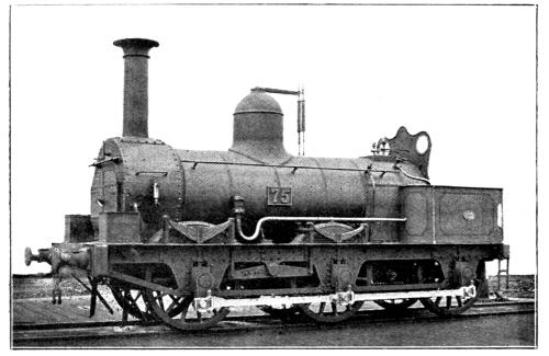
Fig. 81 is a photograph of engine No 75, of the Taff Vale Railway, built at the Company’s Cardiff Works in 1860. The six-coupled wheels were 4ft. 8in. diameter, the cylinders were 16in. diameter, and the stroke was 24in. No. 75 weighed 32 tons in working order; the steam pressure was 130 lbs. per sq. in. She was employed in the heavy mineral traffic of the Taff Vale Railway, and from her design well calculated to work over the heavy gradient of that system.
81.—SIX-COUPLED
MINERAL ENGINE, TAFF
VALE RWY., BUILT 1860
In 1862 the L. and S.W Railway purchased some second-hand engines from a contractor. They were built by Manning, Wardle, and Co., Leeds, and comprised six-wheels-coupled saddle tank engines. The wheels were 3ft. diameter; cylinders, 12in. by 18in. stroke; wheel base, 10ft. 3in.; length over buffers, 21ft. 6in.; weight, empty, 14 tons 8 cwt., loaded, 16 tons 4 cwt. The fire-box was surmounted by a safety valve enclosed within a high fluted pillar. The steam pressure was 120lb. One of these engines is leased to the Lee-onthe-Solent (Light) Railway, and may be seen working the traffic on this little line, which, by the way, spends over twopence to earn each penny of its gross income.
Before leaving the London and South Western Railway and its goods locomotives, it is as well to record the dimensions of the “Meteor,” No. 57, constructed at Nine Elms in 1863 from the designs of Mr. Beattie. The cylinders were 16½in. diameter, 22in. stroke; the leading wheels were 3ft. 3in., and the coupled (D. and T.) wheels 5ft. diameter; the wheel base was 14ft., of which 8ft. 2½in. was between the coupled wheels. The leading wheels were under the boiler, and the front buffer beam was about 6ft. in advance of the centre of this
axle. An immense dome was fixed on the raised fire-box; the safety valve was within an inverted urn-shaped case on the boiler barrel. The weather-board had slight side-wings, and was curved upwards at the top, and so formed an incipient cab. The fire-box sloped from the tube-plate towards the foot-plate. The total weight, in working order, was 32 tons 18 cwt., of which 11 tons 9 cwt. was on the leading, 11½ tons on the driving, and 9 tons 18 cwt. on the trailing axle. The tender was supported on six wheels, 3ft. 9¾in. diameter, and had a tank capacity of 1,950 gallons.
By a marvellous addition of a big head and a bigger tail (to say nothing of various legs), the diminutive body of the East Kent Railway had, in August, 1859, blossomed into the London, Chatham and Dover Railway; and for this railway 24 locomotives were supplied by various firms from Crampton’s designs. They were numbered 3 to 26. The design was peculiar—a leading bogie having wheels 3ft. 6in. diameter, and a base of 4ft., and four-coupled wheels 5ft. 6in. diameter. The cylinders were outside, and had a stroke of 22in., the diameter being 16in. As in the “London” and other Crampton engines, the cylinders were placed about midway between the smoke and fire-boxes, whilst the connecting-rods actuated the rear pair of coupled wheels, so that in describing the position of the wheels of these engines we should have to enumerate them as “leading bogie,” “centre,” and “ driving.” A compensation lever connected the centre and driving wheels. Gooch’s valve gear was used. Like other engines of Crampton’s design, this class was a failure, and within three or four years they were rebuilt as six-wheel engines, with inside cylinders and outside frames; some of them, as reconstructed without a bogie, are still in active service on the London, Chatham and Dover Railway.
Before the grave faults inherent in the previously described class of engines had been, fully appreciated, the London, Chatham, and Dover Railway had arranged for a second batch of engines from another of Crampton’s designs. These consisted of five engines constructed by R. Stephenson and Co. in 1862. The locomotives in question were worked on the principle patented by W. Bridges Adams, and previously described in an earlier chapter—viz., an
intermediate driving shaft, coupled by outside rods to the driving wheels, situated behind the fire-box. The cylinders were 16in. diameter by 22in. stroke, and within the frames. The driving wheels were 6ft. 6½in. diameter, and bogie wheels 4ft. 0½in. diameter. Cudworth’s sloping fire-box, fitted with a longitudinal mid-feather, was employed. The heating surface amounted to 1,200 sq. ft., made up of 130 sq. ft. fire-box and 1,070 sq. ft. tubes, which were 2in. diameter, 10ft. 10in. long, and 189 in number. The grate area was 26 sq. ft.
The engines in question were named, etc., as follows:—
As remarked in describing the previous class, Crampton’s engines were in this case also found to be unsuitable, so that the London, Chatham and Dover Railway rebuilt the five engines, when the intermediate driving shaft was provided with a pair of wheels, and the engines became “four-coupled bogies.” The diameter of the cylinders was increased to 17in.; the Cudworth fire-box was dispensed with, and the heating surface reduced, the present dimensions being—fire-box, 100 sq. ft.; tubes, 987 sq. ft.; grate area, 16¼ sq. ft.; weight in working order: on bogie, 14 tons 12 cwt.; driving wheels, 14 tons 12 cwt.; and on trailing wheels, 10 tons; total, 38 tons 16 cwt.
CHAPTER XII.
“Brougham,” Stockton and Darlington Railway L & N W R engines at the 1862 Exhibition Sinclair’s “Single” engines for the G E R French locomotives on the G E R L & S W R tank engines, afterward converted to tender engines Conner’s 8ft 2in “Single” engine on the Caledonian Railway The lilliputian “Tiny,” the Crewe Works locomotive “Dignity and Impudence” Bridges Adams’ radial axle tank engines His springtyres Account of the St Helens Railway locomotive with these innovations Broad-gauge engines for the Metropolitan Railway Rupture between the Great Western and Metropolitan Sturrock to the rescue G N tender engines on the Metropolitan Delivery of the Underground Company’s own engines Great Northern “condensing” locomotives The Bissell bogie truck well advertised End of the “hot-brick” engine Sturrock’s steam-tender engines on the G N R Sinclair’s tank engine with Bissell trucks Fell’s system of locomotive traction Tried on the Cromford and High Peak line Adopted on the Mount Cenis Railway Spooner’s locomotives for the Festiniog Railway Fairlie’s double-bogie engines The “Welsh Pony” and “Little Wonder” Fairlie’s combined trains and engines Cudworth’s trailing bogie North London engines, a model for tank locomotive constructors Pryce’s designs for the North London Railway
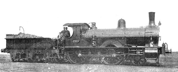
Fig.82 illustrates the “Brougham,” No. 160, of the Stockton and Darlington Railway. This engine was designed for hauling passenger trains. She was a bogie engine, as will be noticed by reference to the illustration, and had four-coupled wheels 6ft. in diameter. The cylinders, placed outside, were 16in. in diameter, with a stroke of 24in. The tender was on six wheels, and the tank was capable of carrying 1,400 gallons. No. 160 was constructed in 1860, not a very long time prior to the amalgamation with the NorthEasternRailwayCompany,byR.StephensonandCo.,of Newcastle, ata costof £2,500.
The London and North Western Railway exhibited at the London International Exhibition of 1862 a locomotive constructed at Wolverton from the designs of Mr. McConnell; the engine was built the previous year, was numbered 373, and named “Caithness.” The cylinders were 18in. by 24in.; driving wheels, 7ft. 7⅛in. diameter; L. and T., 4ft. 7½in.; steam pressure, 150lb.; wheel base, 18ft.; heating surface (14 tubes 1⅞in. diameter, 9ft. 4in. long), 980.319 sq. ft.; fire-box, 242.339 sq. ft.; weight in working order (engine and tender) 59 tons 14 cwt. A combustion chamber 2ft. 8in. long was provided. Two other engines of this design were built, No. 372 “Delamere” and No. 272 “Maberley.” Apparently theseengineswerenotverysuccessful,as we do notfindaccountsof theirlaterperformances.
In 1862 Fairbairn and Co. constructed for the Great Eastern Railway a class of “single” engines designed by Mr R. Sinclair These locomotives had outside cylinders, 16 ft. by 24 in.; driving wheels, 7 ft. 3 in., and leading and trailing wheels, 3 ft. 9 in. diameter; heating surface, tubes (203, 1¾ in. diameter), 957.6 sq. ft.; fire-box, 94.9 sq. ft.; grate area, 15.27 sq. ft.; weight, 32 tons, of which 13 tons 13cwt.1qr.wasonthedrivingaxle.Gooch’slink motionwasemployed.
F��.82.—“BROUGHAM,” No.160,STOCKTON AND DARLINGTON RAILWAY
The design in question was of rather attractive appearance, the open splasher being an attractive feature, as was also the cab—somewhat of an innovation 35 years ago. Mr S. W Johnson succeeded Mr Sinclair at the end of 1865 as Great Eastern Railway locomotive superintendent, and under the régime of the former some of these engines were rebuilt with a leading bogie, and the diameter of the cylinders was increased to 18 in. Another form of cab was introduced, the Salter safety valve on the dome was removed, and one of Ramsbottom design placed on the flush top fire-box, which had superseded the raised pattern as employed in this class of engine by Mr Sinclair One of the engines of this class (No. 0295) was in active service as recently as July, 1894. In connection with this class of engine a special circumstance needs mention—viz., that 16 of these locomotives were made—not “in Germany,” but in the country of her foe; the French engineering firm with the German name of Schneider, in 1865, contracting to supply the 16 locomotives at a less price than any English maker This event was certainly a curiosity in the economic history of this country’s trade. We import many articles; let us hope, however, that foreign locomotives will not again be seen on English railways. There is some consolation to be found in the statement that all the British locomotive builders were so full of orders at the time that they practically refused to accept orders for the engines in question by tendering forthematoutsideprices,sothatconsequently the orderhadto begivento aforeignfirm.
In 1863 Beyer, Peacock and Co. commenced to construct a class of tank engines for the London and South Western Railway from the designs of Mr J. Beattie. The locomotives in question had outside cylinders 16½in. by 20in. stroke; four coupled wheels, 5ft. 7in. diameter; and a pair of leading wheels, 3ft. 7¾in. diameter The boiler contained 186 tubes, 1⅝in. diameter The heating surface was made up oftubes715.17sq.ft.,andfire-box80sq.ft. The grate areawas 14.2sq. ft.
A lock-up safety valve was placed on the front ring of the boiler barrel, and two of Salter’s pattern on the immense dome which surmounted the raised fire-box The steam pressure was 130lb. The engine weighed in working order 29 tons 17 cwt., of which 10½ tons was on the driving axle. We have already stated that the engines were built as tanks, but Mr W Adams, who had succeeded Mr J. Beattie as locomotive superintendent of the London and South Western Railway, added tenders to some of their engines in 1883. It is a common practice to rebuild tender engines as “tanks,” but the opposite practice is somewhat of a novelty The tenders were supported on six wheels, 3ft. 9¾in. diameter, and weighed 20¾tonsinworkingorder,thewatercapacity being 1,950gallons.
An engine that attracted considerable attention at the 1862 Exhibition was one built by Neilson and Co. from the designs of Mr B Conner, locomotive superintendent of the Caledonian Railway (Fig. 83). The engine in question had outside cylinders, 17¼in. diameter, with a stroke of 24in.; driving 8ft. 2in. in diameter, with inside bearings and underhung springs. The trailing and leading wheels had outside bearings. The engine had 1,172 sq. ft. of heating surface; the grate area was 13.9 sq. ft.; wheel base, 15ft. 8in.; weight, empty, 27¼ tons; in working order, 30 tons 13 cwt., of which 14 tons 11 cwt. was on thedrivingaxle.
Colburn describes the locomotive as a “fine, well-constructed engine, standing gracefully on its wheels, large, yet compact, and qualified to run at any speed with ease and steadiness.” Nor can this description be in any measure contradicted. For, until Stirling built his famous 8ft. 1in. “singles” for the Great Northern Railway, Conner’s 8ft. 2in. Caledonian engines were far and away the most graceful locomotives ever placed on the 4ft. 8½in. gauge. In general design, the engine was a modification of the
old Crewe pattern engine. The dome was, however, of rather a peculiar shape: it was placed on the top of the raised fire-box. The driving axle was of cast steel, and the tyres of Krupp steel. The large number of spokes in the driving wheels was noticeable, being at only 10in. centres at the rim of the wheels. The slide-valves were provided with 1½in. lap. A great improvement was the provision of a cab, and that of not disproportionate dimensions, considering the “year of grace” in which the engine was constructed. Trains of nine carriages were hauled at an average speed of 40 miles an hour, with a coal consumption of 2½lb. per mile; 14 loaded carriages were frequently taken up the terrible Beattock bank, 10 miles in length,at30milesanhour
The late Khedive of Egypt was so taken with the appearance of this engine when it was at the Exhibition that he immediately ordered one for his own railway. He was searching for a locomotive to convey him at 70 miles an hour, and Conner’s 8ft. 2in. single appeared to be the one most likely to fulfil hisrequirements.Nordowehearthathe wasinanyway disappointed withhis purchase.
It is interesting to know that the Caledonian Railway has still a specimen of this notable design unscrapped—may it ever remain so. To prevent our appetite becoming vitiated with a galaxy of Brobdingnagian locomotives, we will descend to the other end of the scale, and detail the Lilliputian “Tiny,” as used in the Crewe locomotive works. The railway is of 18in. gauge, and was opened in May, 1862, for a length of three-eighths of a mile. In its course the engine traverses curves of 15ft. radius each, no difficulty being found in going round these curves with loads of 12 to 15 tons, or in taking 7ft. 6in. wheel forgings or tyres on edge by means of trucks specially adapted for the purpose. This engine has four-wheels-coupled; inside cylinders, 4¼in. diameter, and 6in. stroke; the wheels are 15in. in diameter, on a base of 3ft. The total heating surface is about 42 sq. ft. A No. 2 Giffard’s injector supplied the boiler with water; this precious liquid is stored in a saddle tank, with a capacity of 28 gallons. “Tiny,” when“rightandtightandreadyforaction,”weighsonly2½ tons.
The duties of the Lilliputian engines consist in hauling materials to and from different parts of the works, and as the 18in. rails are in most places laid parallel with the standard gauge lines, “Tiny” is also calledupontoflyshuntthetrucks,etc.,whennecessary
An engine of this type, the “Nipper,” forms with the giant “Cornwall” that well-known photographic picture—therailway“DignityandImpudence.”
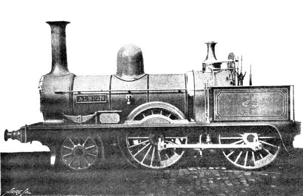
Fig. 84 represents Sharp, Stewart, and Co.’s standard design of passenger engine of this period. The “Albion” was delivered to the Cambrian Railway in May, 1863. She was an inside cylinder engine, with a pair of leading wheels, and an enclosed Salter safety valve. Altogether, the “Albion” is a fair exampleoflocomotivepractice36yearsago.
We have on previous occasions referred to the improvements in locomotive construction introduced by Mr W Bridges Adams, and we now have again to record a successful employment of his design. In the first week of November, 1863, Mr James Cross, locomotive engineer of the St. Helens Railway, completed a tank locomotive, supported on eight wheels, the leading and trailing pairs of which were fitted with the radial axle-boxes patented by Mr W B. Adams; whilst the four coupled wheels were fitted withspringtyres,whichwereanotherinventionof the same engineer.
F�� 84 “ALBION,”
CAMBRIAN RAILWAYS, 1863
The St. Helens Railway was famous—or, from an engineer’s point of view, we should say, perhaps, infamous—for the severe gradients, sharp curves, and numerous points, crossings, and junctions. The inclines were as steep as 1 in 35, 1 in 70, and 1 in 85, whilst the curves were constructed with radii of 300ft. and 500ft., and reverse or S curves were also more frequent than pleasant. The St. Helens Railway was only 30 miles long, but within two miles of the St. Helens Station no less than 12 miles of sidings were located. We do not mean to suggest that the whole line of railway was so thickly covered with siding connections, but such were distributed over the remaining mileage of the railway in too plentiful profusion. Here, then, was a length of railway containing the three great hindrances to smooth and quick running, but the locomotive about to be described was so constructed as to successfully overcometheseimpediments.
This engine had inside cylinders, 15in. diameter and 20in. stroke. The coupled wheels were 5ft. 1in. in diameter, the rigid wheel base being 8ft., but as these wheels had spring tyres, each pair of wheels was practically as free to traverse the curves as uncoupled wheels. Other dimensions were:—Heating surface, 687 sq. ft.; grate area, 16.25 sq. ft.; total wheel base, 22ft.; weight in working order, on leading wheels, 7 tons 15 cwt.; on driving, 11¾ tons; on rear coupled, 11¼ tons; on trailing, 10 tons, including 4¼tonswaterand1¼tonscoal.Totalweight, 40¾tons.
The boiler contained 121 tubes, 10ft. 11in. long, and 1⅞in diameter; steam pressure, 140lb.; water capacity of tank, 950 gallons. The fire-grate was 5ft. long, and sloped from the door to the tube-plate. The springs of the coupled wheels were connected by means of a compensation lever The dome was placed on the raised fire-box, and fitted with a screw-down safety valve; a second valve of the same pattern was fixed on the boiler barrel. A roomy and well-enclosed cab, fitted with side windows, thoroughlyprotectedtheenginemen.
Adams’ radial axle-boxes are, of course, still in use on the Great Northern Railway, London, Chatham, and Dover Railway, and other lines, so that a detailed account here is not necessary, the salient feature being that they are made with a radius, having its centre in the centre of the adjoining axle, the axle-box guide-boxes being curved to fit. In the engine we are now describing the radius of the boxes was 7ft., and the lateral play of the boxes was 4½in. on each side. The spring-pins were not fixed on the top of the boxes, but were each fitted with a small roller to allow the boxes to freely traverse. The axle-boxesweighed3½cwt.each.
It will be understood that when an engine fitted with these boxes enters a right-hand curve the flanges of the leading wheels draw the boxes to the right, so that the engine itself remains a tangent to the curve, whilst, since the axle-boxes are themselves curved, the effect is that the right-hand side axles are brought nearer the rigid wheels, and consequently the radial wheels on the opposite side of the engine further from the fixed wheels, the whole effect of the radial axle-boxes being that the trailing and
leading axles actually become radii of the curves being traversed, although the flanges continue parallel totherails.
Adams’ spring tyres require a more precise description, and before we describe them, readers may perhaps be reminded that Adams had strong views on the subject of railway rolling stock wheels. He enters rather fully into the matter in his book, “Roads and Rails,” especially in the chapter dealing with “the mechanical causes of accidents.” In this, Adams maintains that the usual forms of wheels are in realityrollers,andnotwheels.
The spring tyres had been tried on the North London Railway, Eastern Counties, and on another locomotive on the St. Helens Railway, before the engine now under review was constructed. Upon the coupled wheels of the new locomotive for the latter railway, double spring hoops were employed, the single form having been used in the three previously mentioned engines. The plan adopted was as follows:—
“The tyres chosen were constructed with a deep rib in front; this was bored out, internally, to a depth of ¾in., and to a conical section, and, of course, parallel to the tread. A flat edge, ⅜in. wide, was thus leftoneitherside.
“The springs, formed of tempered hoop steel, were placed on the inner surface of the tyres. Corresponding curves were turned across the outer circumference of the wheels. The wheels were forced into the cones containing the springs, and retained by three 1in. bolts, and a flat ring in the groove at the back of the tyre, the effort of the spring tyres being to allow of a slight lateral motion in running round curves and also to give a better grip of the rails, as the tyres, by reason of the weight upon them being transmitted through the tyre springs, slightly flattened upon the rails, and so presented alargersurfaceforadhesionbetweenthetyres and rails.”
The following interesting account of the working of the radial axle and spring tyre locomotive on the St. Helens Railway is extracted from a paper by Mr J. Cross, the designer of the locomotive, and read before the Institution of Civil Engineers. Mr Cross stated that “the engine was completed in the first week of November, 1863, and has since been running very regularly, taking its turn of duty with passenger trains or coal trains, or as a shunting engine; and about the numerous works connected by sharp curves with the St. Helens line. The motion round curves is free from all jerking, and on straight lines the speed is more than 60 miles an hour; either end of the engine being first, without any train behind to give steadiness; and the motion is so smooth that it has only been by taking the actual time that the engineers have convinced themselves of the fact of the speed exceeding 40 miles an hour. It was built to traverse curves of 200ft. radius. This it does with the greatest facility, and it has regularly worked the passenger trains round a curve of 1,000ft. radius, going directly off the straight line by a pair of facing points at a speed of more than 30 miles an hour, and it has gone round curves of 132ft. radius. It has also run a train of 12 passenger carriages, weighted up to 100 tons, exclusive of its own weight, at 60 miles an hour on the level. From the advantages it possesses over the ordinary mixed engines for weighting the trailing coupled wheel, it, without difficulty, on a wet, slippery day, started, and took this load up a gradient of 1 in 70, drawing seven of the carriages with a load weighing 72 tons 5 cwt., up a gradient of 1 in 36, round a curve of 440ft. radius; and coal trains of 250 tons are worked over long gradientsof1in200withthegreatestease.
“It is evident, then, that engines on this principle, affording facilities for the use of high power in hilly countries, are peculiarly adapted for Metropolitan lines, where sharp curves are a necessity (being equally safe whichever end is foremost), and are also well suited for light lines in India and the Colonies. It may likewise be remarked that carriages and wagons on this principle would carry heavier freights, with a saving in the proportion of dead weight, while their friction round curves would be less than at present.”
The improvements adopted in the construction of this locomotive for the St. Helens Railway were so successful that, as usual, other claimants, who appropriated the radial axle-boxes as their invention, were soon contending with Adams and Cross as to who was entitled to the honour of introducing the improvement.
The first portion of the Metropolitan Railway was opened on January 18th, 1863, and the line was then worked on the broad-gauge by the Great Western Railway for a percentage of the receipts. The
Mr. D. Gooch, in 1862, designed a special class of tank engines for working the Metropolitan Railway They were six-wheel engines, the driving and trailing wheels being 6ft. diameter and coupled. The cylinders were outside. A special form of fire-box and baffle-plate was employed, and tanks were provided beneath the boiler barrel, into which the exhaust steam was discharged by means of a reversing valve fitted to the bottom of the blast pipe. When in the open air, the waste steam escaped up thechimneyintheusualmanner
The first of these engines were named: Bee, Hornet, Locust, Gnat, Wasp, Mosquito, Bug, Khan, Kaiser, Mogul, Shah, and Czar. Later ones were named after flowers and Great Western Railway officers.
A dispute arose between the two companies at the beginning of August, 1865, and immediately developedintoacompleterupture.Thesmaller quasivassal railway, through the energy displayed by its chief officers, successfully overcame the apparently insurmountable obstacles that beset it, and consequently the Metropolitan Railway asserted its complete independence of the Great Western Railway,andhassincemaintainedit.
It was indeed a nine days’ wonder that the Metropolitan Railway was called upon to perform, for it had to obtain from somewhere locomotives and carriages to work the underground line, commencing on themorningofAugust10th,1863.
Mr Sturrock, the locomotive superintendent of the Great Northern Railway, had at this time under construction a class of condensing-tank engines that he had designed to work the Great Northern Railway traffic over the Metropolitan Railway The directors of the Metropolitan Railway in this emergency applied to Mr Sturrock for assistance, and by working day and night he managed to fit up someGreatNortherntenderengineswitha temporarycondensingapparatus.
The difficulty was to provide some kind of condensing apparatus on the Great Northern tender engines, it being necessary to use flexible connecting pipes between the engine and tender strong enough to withstand the steam pressure, but Mr Sturrock was successful enough to contrive the necessary flexible pipes by which the exhaust steam was conveyed from the engine to the water-tank of the tender, but these pipes very frequently burst, and all concerned were far from sorry when the proper enginesweredelivered.
An order for eighteen had already been placed with a well-known Manchester firm of locomotive buildersbytheMetropolitanRailway,Beyer, Peacock,andCo. building them from thedesigns ofthe late Mr.(afterwardsSir)JohnFowler.
The type is well known to London readers, the engines having side tanks, a leading bogie, the wheels of which were 3ft. diameter, with a base of 4ft. The driving and trailing wheels (coupled) were 5ft 9in. diameter, their base being 8ft. 10in.; the total wheel base being 20ft. 9in., or to centre of bogie, 18ft. 9in. The cylinders were outside, slightly inclined from the horizontal, 17in. diameter, and 24in. stroke. The grate area was 19 sq. ft. The fire-boxes had sloping grates, which were 6in. deeper at the front than the back. The boiler barrel was 4ft. in diameter, and 10ft. 3in. long; it contained 166 tubes, 2in. diameter, the total heating surface being 1,014 sq. ft. The working pressure was nominally 130lb. per sq. in., but when working through the tunnels, condensing the steam, and with the dampers closed, a very much lower pressure resulted. The frames were inside, the dome (fitted with a Salter valve) was on the boiler barrel,closetothesmoke-box,asand-boxbeingalsofixedonthe boilerbarrelatthebackof the dome.
The bogie truck was built of plate frames, and was on the Bissell system, turning on a centre-pin fixed to the engine frame, at a radial distance of 6ft. 8in. from the centre of the truck. “Locomotive Engineering” says that “this radial length ensures a nearly correct radiality of the bogie to curves of all radii, the proper length of the radius to ensure exact radiality of the centre of the bogie for all curves being 7ft. 2in., or 6in. more than the actual length—a difference which is, perhaps, of no great importanceinpractice.”
For the purpose of effectually condensing the exhaust steam the side tanks were only filled with water to within 6in. of the top, and the steam was discharged upon the surface of the water, from a 7in. pipe on each side—one to each tank. Into the mouth of these 7in. pipes a 4in. pipe was projected a
short distance, and the other end of the 4in. pipe was below the surface of the water, so that a portion of the steam was discharged right into the water in the tanks, and agitated the water sufficiently to prevent the surface of the water from becoming too hot, as would have been the case if the same portion of the water had always been presented to the waste steam. The tanks held 1,000 gallons, and at the end of a journey the water had become too warm to properly condense the exhaust, and it therefore became necessarytoquicklyemptythetanksandtotake in afreshsupply ofcoldwater
To expeditiously perform the former operation, each tank was provided with a pipe 7in. in diameter; this led to a cast-iron valve-box being placed below the foot-plate. By means of a screw, worked from the foot-plate, a 10in. valve was operated, and the water in the tanks could be discharged into the pits belowtheengineinthecourseofsome60seconds.
The following list gives the names and builders’ numbers of the first locomotives constructed for the MetropolitanRailway:
These engines were fitted with a very small coal bunker, only 18in. wide. Weight of engine in working order: on bogie, 11 tons 3½ cwt.; driving, 15 tons 9½ cwt.; and trailing, 15 tons 10 cwt. Total weight, 42 tons3cwt.
Mr Sturrock’s engines for working the Great Northern trains over the Metropolitan Railway were numbered 241 to 250, their leading dimensions being:—Cylinders (inside), 16½in. diameter, 22in. stroke; leading and driving wheels (coupled), 5ft. 6in.; trailing wheels, 4ft. diameter; wheel base, L. to D., 7ft. 6in.; D. to T., 11ft. 9in.; total, 19ft. 3in. Weight, empty, 32 tons 4 cwt. 1 qr.; in working order, 39 tons 12cwt.2qrs.
These Great Northern Railway locomotives were fitted with Adams’ radial axle-boxes to the trailing wheels,andcommencedworkingattheendof October, 1865.
The patentee of the Bissell bogie truck did not intend to hide the light of his invention under a bushel, for he advertised the improvement in a truly American style. The following advertisement was to be found in the columns of the sober railway newspapers soon after the Metropolitan locomotives were at work:—
“No more accidents from engines running off the line (see Queen’s letter to Railway Directors copiedintherailwaypapersJanuary 28th,1866).
“The Bissell bogie, or safety truck, for locomotive engines, so much prized on American and foreign railroads for the great safety and economy it affords on curved roadways, after years of probationary trial in England, has at length been adopted by John Fowler, Esq., C.E., F.G.S., upon all the new engines, eighteen in number, now working on the Metropolitan Railway, and by Robert Sinclair, Esq., C.E., upon twenty new eight-wheeled engines on the Great Eastern Railway, which may be seen daily The royalty for the use of the Bissell Patents has been reduced to £10 per engine, so that every engine requiring a bogieunderframeshouldbeprovidedwith theBissellsafetytruck. Applyto——.”