Preface
The philosophy of Engineering Heat Transfer is the same as it was when the book was first written—to write a readable, user-friendly book that provides many practical examples, without overwhelming the student. Many students think in concrete terms using pictures to envision what is being discussed. Thus drawings, sketches, graphs, etc., are used extensively in this book to enhance the learning process. Thinking in concrete terms is especially helpful in an area, such as heat transfer, which is highly abstract. Every effort was made to provide many examples and a large number of confidence-building problems. The examples amplify the theory and show how the derived equations are used to model physical problems. Confidence-building problems are relatively simple and to some extent follow the examples. When a few of these types of problems are solved, the student will hopefully feel comfortable with the information and can then apply it with confidence to situations that are not obvious, and that increase in complexity. Problem solving is a skill that must be developed slowly, methodically, and thoroughly. The emphasis is on problems that are practical in nature. Applications of the material make this book interesting.
The new direction in engineering education is the implementation of “design throughout the curriculum.” In addition, the design experience is meant to culminate in capstone courses, such as design of fluid thermal systems or mechanical design. Such necessary courses are taught at the senior level— either fi rst or second semester. Moreover, these capstone design courses require knowledge of certain prerequisites such as fluid mechanics and heat transfer. In many curricula, heat transfer is taught at the junior or fi rst semester-senior level. Rather than being a course in itself, it is now a backbone course for a senior design experience that is supposed to “put it all together.” So the emphasis in this book is on problem-solving skills with real world examples. The niche that this book fi lls is that of a book written with practical applications in mind that can fit into the overall design experience. The time is right to move forward and keep pace with what is occurring in engineering education.
Text Modifications
The previous editions of this book had derivations of the Navier–Stokes equations in three coordinate systems. They also contained the derivations of the boundary layer equations, integral methods of solution, etc. As such, they were aimed originally at the senior mechanical engineering student who wanted to go to graduate school. The integral method for solution of the boundary layer equations, although interesting and clever, does not help a senior-level student learn how to design anything. Therefore, the current edition has been modified to make it better suited for an emerging place in the mechanical engineering curriculum. The objective here is to produce a revised book for a new market.
Chapter 1 of the third edition of Engineering Heat Transfer provides an introduction to heat transfer and to the tables at the end of this book. Chapter 2 discusses one-dimensional conduction. Heat flow through walls, cylinders, and fi ns are all considered.
Chapter 3 discusses steady-state conduction in multiple dimensions. The analytical method of solution applied to a simple problem is presented to illustrate the mathematical complexity of such problems. Next, alternative solution methods, including graphical and numerical methods, are presented. Much of the material in the fi rst three chapters has been reorganized.
Chapter 4 discusses unsteady-state heat conduction, and it contains the lumped capacitance method as well as Heisler charts for more complex problems. Heisler charts have been modified to make them easier to read in the regions where the Fourier number is very small.
Chapter 5 provides an introduction to convection. A discussion of basic fluid mechanics is given, which serves as an overview of the convection chapters that follow. The Navier–Stokes equations are presented but not derived. The thermal energy equation is derived; however, the equations are used to solve problems in laminar flow for which there are exact solutions.
Chapter 6 discusses convection heat transfer in closed conduits. Circular and noncircular ducts are both discussed. Empirical correlations are also provided. Chapter 7 discusses convection heat transfer in flow past immersed bodies. Boundary layer flows are described but boundary layer equations are not derived. Descriptions and correlations are provided for various flows—flow over a flat plate, flow past two- and three-dimensional bodies, and flow past a bank of tubes.
Chapter 8 discusses natural convection. Problems considered are vertical surfaces, inclined surfaces, horizontal surfaces, cylinders, and arrays of fi ns. Chapter 9 discusses heat exchangers including double pipe, shell and tube, and cross flow. Both of these chapters are essentially unchanged from the previous edition.
Chapter 11 gives an introduction to radiation heat transfer. Topics include the electromagnetic radiation spectrum, emission and absorption, intensity, radiation laws, and characteristics of real surfaces. Chapter 12 discusses radiation heat transfer between surfaces. The view factor and methods for evaluating it are presented. Heat transfer within enclosures of black and gray surfaces is modeled.
Problems at the end of each chapter have been reorganized and classified according to the topic. In many cases, the instructor may not wish to cover certain sections in the chapter and such a reorganization makes it simple to select the desired problems appropriately.
The writing style conveys my enthusiasm for the material, and hopefully students will get as excited about solving heat transfer problems as I am.
Acknowledgments
Great appreciation to Jonathan Plant, engineering editor for CRC Press, Boca Raton, Florida, for his support in producing a third edition, and for providing much encouragement at critical times; to Arlene Koppelof, and all who helped at CRC Press, and to The University of Memphis for support in various ways; and especially to my lovely wife, Marla, whose unfailing moral support was always there when it was needed.
Author
Dr. William S. Janna received a BSME degree, an MSME, and a PhD from the University of Toledo. He joined the mechanical engineering faculty at The University of New Orleans in 1976, where he became department chair, and served in that position for 4 years. Subsequently, he joined The University of Memphis in 1987 as chair of the Department of Mechanical Engineering. Dr. Janna served as associate dean for graduate studies and research in the Herff College of Engineering. His research interests include boundary layer methods of solution for various engineering problems, modeling the melting of ice objects of various shapes, and the study of sublimation from various geometries. Dr. Janna is the author of three textbooks, and a member of the American Society of Mechanical Engineers (ASME). He teaches courses in heat transfer, fluid mechanics, and design of fluid/thermal systems. He has designed and constructed a number of experiments in fluid mechanics and heat transfer laboratories.
1 Fundamental Concepts
1.1 Introduction
Heat transfer is the term applied to a study in which the details or mechanisms of the transfer of energy in the form of heat are identified and modeled. There are many examples of heat transfer. Familiar domestic examples include broiling a turkey, toasting bread, and heating water. Industrial examples include curing rubber, heat treating steel forgings, and dissipating waste heat from a power plant. The analysis of such problems is the topic of study in this text.
1.2 Mechanisms of Heat Transfer
Heat transfer is energy in transit, which occurs as a result of a temperature gradient or difference. Th is temperature difference is thought of as a driving force that causes heat to flow. Heat transfer occurs by three basic mechanisms or modes—conduction, convection, and radiation.
Conduction is the transmission of heat through a substance without perceptible motion of the substance itself. Heat can be conducted through gases, liquids, and solids. In the case of fluids in general, conduction is the primary mode of heat transfer when the fluid has zero bulk velocity. In opaque solids, conduction is the only mode by which heat can be transferred. The kinetic energy of the molecules of a gas is associated with the property we call temperature. In a high-temperature region, gas molecules have higher velocities than those in a low-temperature region. The random motion of the molecules results in collisions and an exchange of momentum and energy. When this random motion exists and a temperature gradient is present in the gas, molecules in the high-temperature region transfer some of their energy, through collisions, to molecules in the low-temperature region. We identify this transport of energy as heat transfer via the diff usive or conductive mode.
Conduction of heat in liquids is the same as for gases—random collisions of high-energy molecules with low-energy molecules causing a transfer of heat. The situation with liquids is more complex, however, because the molecules are more closely spaced. Therefore, molecular force fields can have an effect on the energy exchange between molecules because molecular force fields can influence the random motion of the molecules.
Conduction of heat in solids is thought to be due to motion of free electrons, lattice waves, magnetic excitations, and electromagnetic radiation. The motion of free electrons occurs only in substances that are considered to be good electrical conductors. The theory is that heat can be transported by electrons (known as the electron gas), which are free to move through the lattice structure of the conductor in the same way that electricity is conducted. This is usually the case for metals.
The molecular energy of vibration in a substance is transmitted between adjacent molecules or atoms from a region of high to low temperature. Th is phenomenon occurs from lattice waves that can be considered as energy being transmitted by a gas composed of an integral number of quanta, known as phonons. Phonon motion is thought of as diff using through the lattice in the same way as the electron gas does. The lattice-wave mechanism is usually not a significant factor in conduction of heat through metals. It is significant for nonmetals.
Magnetic dipoles of adjacent atoms in some cases provide effects between magnetic moments that may aid the conduction of heat in the solid. Electromagnetic radiation in translucent materials may have an effect on the conduction of heat. Th is is the case when the material has little capacity for absorbing energy.
The concern here is not so much in describing the molecular or microscopic activity associated with conduction, but in being able to describe mathematically the macroscopic effect of heat transfer via the conduction mode. An example of conduction heat transfer is the cooling or freezing of the ground during winter.
Convection is the term applied to heat transfer due to bulk movement of a fluid. Fluid mechanics therefore plays an important part in the analysis of convection problems. Consider a gas furnace for example. Combustion of natural gas yields products that heat a device known as a heat exchanger. A fan blows air over the opposite side of the exchanger. The air movement is caused by an external driving force—the fan. The air absorbs heat (gains energy) from the exchanger by convection. Moreover, to denote that an external device provides fluid movement that enhances heat transfer, the mode of energy transport is called forced convection.
Consider next a domestic gas-fired water heater. Gas is burned in the bottom of the heater. Combustion gases exhaust through tubes in the tank. The tubes are surrounded by water, which gains energy or absorbs heat from them. There will exist a movement of the water within the tank. As water near the tubes receives energy, the local water density decreases. The warmed water tends to rise to the top of the tank whereas cooler water is drawn to the tank bottom. Heat is transferred to the water by convection. Moreover, to denote that bulk fluid movement is caused by density differences resulting from the process of energy transfer, the mode of heat transfer in this case is called natural or free convection. Radiation is the transfer of energy by electromagnetic radiation having a defi ned range of wavelengths. One example of radiant heat transfer is that of energy transport between the sun and the earth. Note that all substances emit radiant heat, but the net flow of heat is from the high- to low-temperature region. So the cooler substance will absorb more radiant energy than it emits.
Heat is usually transferred by a combination of conduction, convection, and radiation. As an example, consider the sidewalk sketched in Figure 1.1. The sidewalk receives radiant energy from the sun. Some of this energy is absorbed, increasing the temperature of the sidewalk. Some of the radiant energy is reflected and, due to the opaque nature of the material, none of the radiant energy impacting the sidewalk is transmitted. As the sidewalk becomes warmer, it radiates more energy. Also, heat is transferred by natural or forced convection (depending on the wind) to the air in contact with it. Finally, heat is transferred by conduction through the sidewalk to the ground below. Th e general heat-transfer problem involving all three modes can be set up and described mathematically. Solving the equations analytically, however, is not always possible. In a number of cases, one mode of heat transfer is dominant. It can then be identified and modeled satisfactorily to obtain a solution to what could be an otherwise insolvable problem. Consequently, conduction, convection, and radiation are presented here in separate discussions. In problems where combined models can be treated, an appropriate model is presented.
Radiant energy reflected and emitted
Radiant energy absorbed
Energy transfer by natural or forced convection to air
Sidewalk (concrete slab)
Heat conducted through the sidewalk to the ground below
FIGURE 1.1 A multimode heat-transfer example.
It is important to develop a method for solving heat-transfer problems. The flow of heat is not a visual experience in most cases. Consequently, it is advantageous to approach a problem by fi rst expressing what is physically happening and then stating the assumptions to be made These two steps will illustrate how the assumptions simplify the problem and how well the model fits the situation. Moreover, these steps show where sources of error will originate. One additional aid in setting up the problem is sketching a temperature profi le , if appropriate. The gradients are then identified, and the direction of heat flow is discernible.
It must be emphasized that much thought should go into understanding the physics of the problem to identify what is really happening, and then to make necessary assumptions so that a mathematical model of the phenomenon can be composed. Th is technique of model formulation will provide a consistent, methodical approach that leads to the development of an intuition or feel for heat-transfer problems. However, the problem should not be overcomplicated. Keep in mind that the objective is to model a physical situation suitably, and to obtain an appropriate and reasonable solution.
1.3 Dimensions and Units
A physical variable used to provide a specification of a particular system is a dimension. A dimension can be either fundamental or derived. In this study, fundamental dimensions have been selected that will be used in combination to make up derived dimensions. The dimensions that are considered fundamental depend on the unit system selected. For example, the fundamental dimensions in the English Engineering system are as follows:
English Engineering System
Dimension (Symbol)
Length (L)
Time (T)
Mass (M)
Force (F)
Temperature (t)
Unit (Abbreviation)
Foot (ft)
Second (s)
Pound mass (lbm)
Pound force (lbf)
Degree Rankine (°R) or degree Fahrenheit (°F) (°R is the absolute unit)
All physical quantities can be expressed in terms of the fundamental units. To relate the units for force and mass, Newton’s second law of motion is used. Newton’s second law states that force is proportional to the time rate of change of momentum
mV t d d ()
where F is force, m is mass, V is velocity, and t is time. Introducing a proportionality constant, we get
()
For constant mass, the preceding equation becomes
where a is acceleration. By defi nition, a force of 1 lbf acting on an object having a mass of 1 lbm will accelerate the object at a rate of 32.174 ft /s2 . Substituting these values in Equation 1.1 yields
lbflbmft/s 2 K ()(.)
Solving for the reciprocal of the proportionality constant gives
It is important to note that gc is a proportionality constant or conversion factor that arises in the English Engineering system of units when relating force to mass units.
The fundamental dimensions in Système International (SI) units are as follows:
SI Units
Dimension (Symbol)
Length (L)
Unit (Abbreviation)
Meter (m)
Time (T ) Second (s)
Mass (M) Kilogram (kg)
Temperature (t) Degree Kelvin (K) or degree Celsius (°C) (K is the absolute unit)
Here again, all physical quantities can be expressed in terms of these fundamental units. Force in this unit system is not considered a fundamental dimension but, instead, is related to mass by the defi nition
1 1 2 N kgm s
TABLE 1.1 Conventional System of Units
English EngineeringSI British Gravitational British Absolute CGS Absolute Mass (fundamental)lbm kg lbmgram Force (fundamental)lbf lbf
Mass (derived) —slug Force (derived) N —poundaldyne
Length ft mft ft cm
Time s s s s s
(°F) gc 32.174 lbm ∙ ft lbf ∙ s12
Note: Degrees Kelvin is (by convention) properly written without the (°) symbol.
where N is the abbreviation for newton, the force unit in SI. In the Engineering System, where force and mass are both fundamental units, a conversion factor must appear in the appropriate equations to make them dimensionally consistent. In SI units, the conversion factor gc is not necessary because the units automatically incorporate the effect. Both of these unit systems will be used in this chapter. Although SI units have been adopted as a standard by many, if not all, professional and technical engineering societies, it will take considerable time for a complete conversion to occur. Therefore, it is premature at this time to exclude either unit system from this text. Equations will contain gc in appropriate places; ignore gc in the equations when using SI units. Appendix Table A.1 provides a list of prefi xes that have been adopted for use with the SI units for convenience. Other unit systems that have been popular at one time or another are summarized in Table 1.1
In a number of cases, it will be necessary to convert from one set of units to another. To make this task easier, a conversion-factor table is provided as Appendix Table A.2 . The quantities are listed with conversion factors that transform a given unit to the SI equivalent.
Work and energy have the same dimension. The dimension for work arises from its defi nition—force times the distance through which the force acts (F · L). The ft · lbf is the unit for work in the Engineering System, and the joule is the unit for work in SI (1 J = 1 N · m = 1 kg · m 2/s2).
The unit for heat in the Engineering System arises from a defi nition also. The British Thermal Unit (BTU) may be defi ned as the amount of heat necessary to raise the temperature of 1 lbm of water at 68°F by 1°F. In SI, the unit for heat is the joule (J).
The fi rst law of thermodynamics and the concept of energy relate work to heat. The term energy encompasses both heat and work. Consequently, the traditional engineering units used for heat and work can be considered as being just different energy units that are related by appropriate conversion factors. The BTU can be converted to other units by 1 BTU = 778.16 ft · lbf = 1.055 J = 1.055 kJ. (Note that there are certain conventions to be followed when using SI units. One convention is to leave a space where one might normally place a comma.) Power, work per unit time, has the dimensions of F · L/T (watt = 1 W = 1 J/s = 1 N · m/s = 1 kg · m 2/s3; 1 horse power (HP) = 550 ft · lbf/s).
1.4 Fourier’s Law of Heat Conduction
Consider the experimental setup shown in Figure 1.2 . A slab of material is in contact with a heat source, a hot plate, on its lower surface, which keeps that surface at an elevated temperature T1. The upper surface of the slab is in contact with a cooling system that absorbs heat and maintains the upper surface at some lower temperature T2 . The area of contact between the plate and both surfaces is A. Heat is conducted through the slab in only one direction, perpendicular to the area of contact, from the hot plate to the cooling water. We now impose a coordinate system on the slab with x directed as shown. If the system is at steady state, and if temperature could be measured at each point within the slab and plotted
as on the figure, the graph of T versus x would result. The slope of this curve is dT/dx. If this procedure is repeated for different materials, the data would lead us to conclude that the flow of heat per unit area is proportional to the temperature difference per unit length. In differential form
where qx is the heat flow in the x direction, A the area normal to the heat flow direction, and dT/dx the temperature gradient or slope of the temperature curve. Note that as x increases, temperature decreases so that the right-hand side of the preceding equation is actually a positive quantity. After substitution and insertion of a proportionality constant in Equation 1.4, we get
where k is the thermal conductivity of the material. The minus sign ensures that the equation properly predicts that heat flows in the direction of decreasing temperature. That is, if temperature decreases with increasing x, then (dT/dx) is actually a negative quantity, and the minus sign of Equation 1.5 ensures that qx will be positive. Conversely, if temperature increases with increasing x, (dT/dx) is positive, and qx is negative. In either case, heat flows in the direction of decreasing temperature. Equation 1.5 is known as Fourier’s law of heat conduction. It is an experimentally observed law and serves as a definition for a new property of substances called the thermal conductivity. The dimension of heat flow qx is energy per unit time, F · L/T (W or BTU/hr; although BTU/s is appropriate, BTU/hr is customarily used instead). The dimension of thermal conductivity k is energy per time per length per temperature, F · L/(L · T · t); [W/(m · K) or BTU/hr · ft · °R]. Note that the unit for time in the Engineering System is the second (s), but thermal-conductivity units are customarily expressed in terms of hours (hr). The quantity qx /A is called the heat flux and is at times written as q ″ x
Equation 1.5 can be simplified and integrated to obtain an equation for the temperature
FIGURE 1.2 Experiment for observing Fourier’s law of heat conduction.
where the temperature is T1 at x = 0 and T2 at x = L . For constant heat flux and constant thermal conductivity, we obtain after integration
Example 1.1
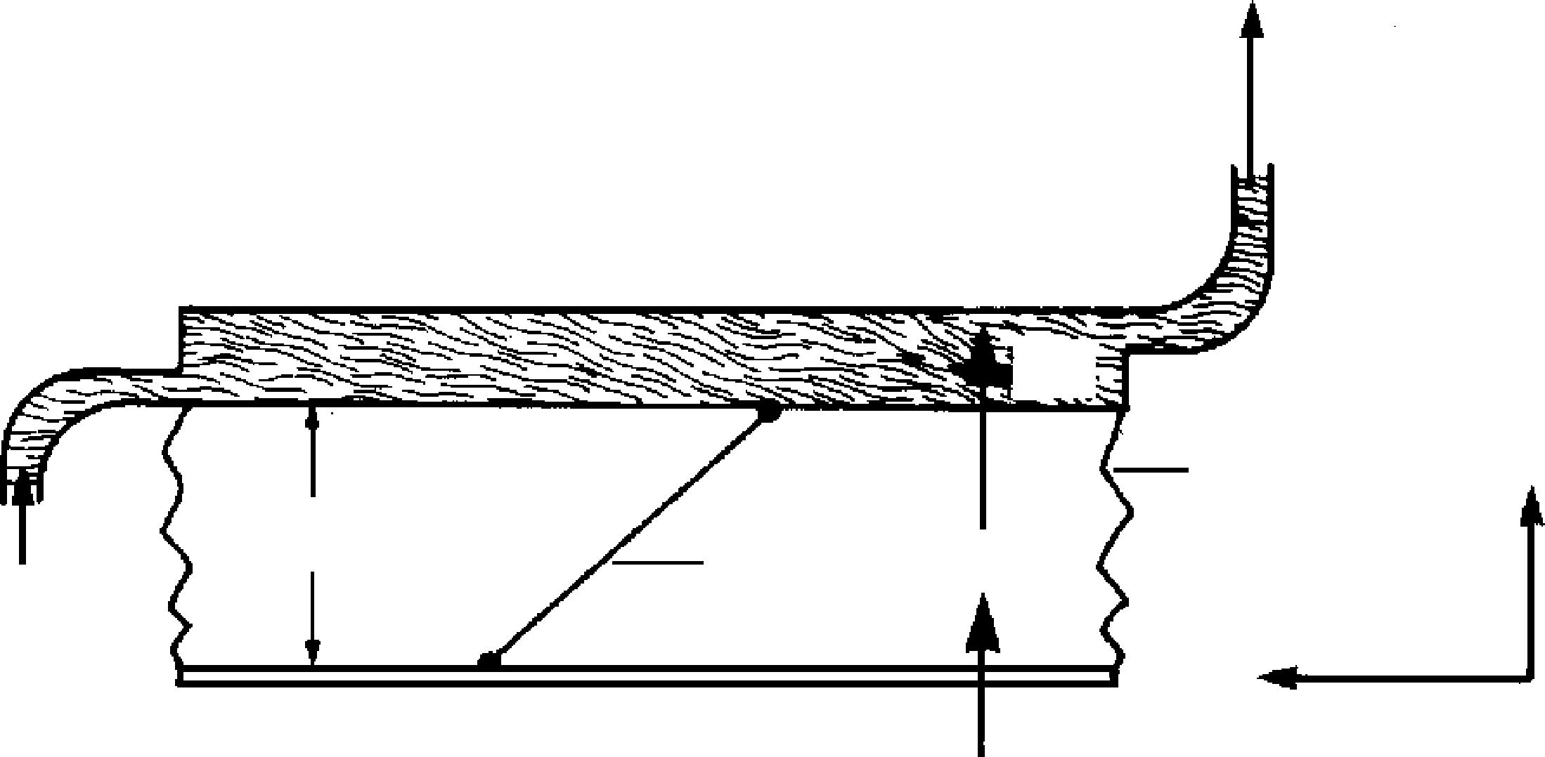
Figure 1.3 is a sketch of a guarded-hot-plate apparatus, which is used primarily for measuring thermal conductivity of an insulating material. The heat source is the main heater. To retard heat flow in any lateral direction (from the main heater), guard heaters are placed next to the main heater. Thus heat is made to flow in one direction from the main heater, through two samples of the material to be tested, to the cooled chambers. Temperature is measured with thermocouples at surfaces 1, 2, and 3. By measuring voltage and current in the main heater, the heat flow through both samples can be calculated.
Suppose the thermal conductivity of glass fiber is to be measured. Two samples 3 cm thick are cut and placed in a guarded-hot-plate device. The voltage across the heater is 120 V, and at this value the heater draws 2 A. The surface temperature at 1 is determined to be 130°C. The temperatures at 2 and 3 are both 25°C. Determine the thermal conductivity. Take the area of contact to be 1 m 2 .
Solution
Before making any calculations, we will describe what is physically occurring. Energy supplied to the main heater is transferred to both material samples. As there are no fluids involved, conduction is the only mode of heat transfer. Figure 1.3 also illustrates the expected temperature profi le of one sample within the apparatus.
Assumptions
1. The surface at 1 is at a constant and uniform temperature of 130°C.
2. The surfaces at 2 and 3 are at a constant and uniform temperature of 25°C.
3. Half the energy supplied to the heater is transferred to each sample with no losses to be accounted for.
4. The system is at steady state.
FIGURE 1.3 The guarded-hot-plate apparatus for measuring thermal conductivity of an insulation.
Equation 1.7 therefore applies
from which we obtain
The energy transferred through each material is half that of the power input.
Substituting, we fi nd the thermal conductivity of the material to be
or
Note that the temperature unit in the denominator of this result is K whereas the temperature difference is expressed in °C. If each temperature is fi rst converted to K, the difference will still have the same numerical value as the °C calculation. Consequently, the temperature unit in the denominator of the thermal conductivity should be thought of as referring to a temperature difference. Remember that a 1°C difference equals a 1 K difference. Likewise, a 1°R difference equals a 1°F difference.
1.5 Thermal Conductivity
As mentioned earlier, Equation 1.5 serves as a defi ning expression for thermal conductivity
Thermal conductivity is a property of a material. The numerical value of thermal conductivity is an indication of how fast heat is conducted through a material and is a macroscopic representation of all the molecular effects that contribute to the conduction of heat through a material. Based on Equation 1.7, measurements can be made to determine thermal conductivity for various substances.
Another random document with no related content on Scribd:
1.F.2. LIMITED WARRANTY, DISCLAIMER OF DAMAGESExcept for the “Right of Replacement or Refund” described in paragraph 1.F.3, the Project Gutenberg Literary Archive Foundation, the owner of the Project Gutenberg™ trademark, and any other party distributing a Project Gutenberg™ electronic work under this agreement, disclaim all liability to you for damages, costs and expenses, including legal fees. YOU AGREE THAT YOU HAVE NO REMEDIES FOR NEGLIGENCE, STRICT LIABILITY, BREACH OF WARRANTY OR BREACH OF CONTRACT EXCEPT THOSE PROVIDED IN PARAGRAPH 1.F.3. YOU AGREE THAT THE FOUNDATION, THE TRADEMARK OWNER, AND ANY DISTRIBUTOR UNDER THIS AGREEMENT WILL NOT BE LIABLE TO YOU FOR ACTUAL, DIRECT, INDIRECT, CONSEQUENTIAL, PUNITIVE OR INCIDENTAL DAMAGES EVEN IF YOU GIVE NOTICE OF THE POSSIBILITY OF SUCH DAMAGE.
1.F.3. LIMITED RIGHT OF REPLACEMENT OR REFUND - If you discover a defect in this electronic work within 90 days of receiving it, you can receive a refund of the money (if any) you paid for it by sending a written explanation to the person you received the work from. If you received the work on a physical medium, you must return the medium with your written explanation. The person or entity that provided you with the defective work may elect to provide a replacement copy in lieu of a refund. If you received the work electronically, the person or entity providing it to you may choose to give you a second opportunity to receive the work electronically in lieu of a refund. If the second copy is also defective, you may demand a refund in writing without further opportunities to fix the problem.
1.F.4. Except for the limited right of replacement or refund set forth in paragraph 1.F.3, this work is provided to you ‘AS-IS’, WITH NO OTHER WARRANTIES OF ANY KIND, EXPRESS OR IMPLIED, INCLUDING BUT NOT LIMITED TO WARRANTIES OF MERCHANTABILITY OR FITNESS FOR ANY PURPOSE.
1.F.5. Some states do not allow disclaimers of certain implied warranties or the exclusion or limitation of certain types of damages. If any disclaimer or limitation set forth in this agreement violates the law of the state applicable to this agreement, the agreement shall be interpreted to make the maximum disclaimer or limitation permitted by the applicable state law. The invalidity or unenforceability of any provision of this agreement shall not void the remaining provisions.
1.F.6. INDEMNITY - You agree to indemnify and hold the Foundation, the trademark owner, any agent or employee of the Foundation, anyone providing copies of Project Gutenberg™ electronic works in accordance with this agreement, and any volunteers associated with the production, promotion and distribution of Project Gutenberg™ electronic works, harmless from all liability, costs and expenses, including legal fees, that arise directly or indirectly from any of the following which you do or cause to occur: (a) distribution of this or any Project Gutenberg™ work, (b) alteration, modification, or additions or deletions to any Project Gutenberg™ work, and (c) any Defect you cause.
Section 2. Information about the Mission of Project Gutenberg™
Project Gutenberg™ is synonymous with the free distribution of electronic works in formats readable by the widest variety of computers including obsolete, old, middle-aged and new computers. It exists because of the efforts of hundreds of volunteers and donations from people in all walks of life.
Volunteers and financial support to provide volunteers with the assistance they need are critical to reaching Project Gutenberg™’s goals and ensuring that the Project Gutenberg™ collection will remain freely available for generations to come. In 2001, the Project Gutenberg Literary Archive Foundation was created to provide a secure and permanent future for Project Gutenberg™ and future generations. To learn more about the
Project Gutenberg Literary Archive Foundation and how your efforts and donations can help, see Sections 3 and 4 and the Foundation information page at www.gutenberg.org.
Section 3. Information about the Project Gutenberg Literary Archive Foundation
The Project Gutenberg Literary Archive Foundation is a nonprofit 501(c)(3) educational corporation organized under the laws of the state of Mississippi and granted tax exempt status by the Internal Revenue Service. The Foundation’s EIN or federal tax identification number is 64-6221541. Contributions to the Project Gutenberg Literary Archive Foundation are tax deductible to the full extent permitted by U.S. federal laws and your state’s laws.
The Foundation’s business office is located at 809 North 1500 West, Salt Lake City, UT 84116, (801) 596-1887. Email contact links and up to date contact information can be found at the Foundation’s website and official page at www.gutenberg.org/contact
Section 4. Information about Donations to the Project Gutenberg Literary Archive Foundation
Project Gutenberg™ depends upon and cannot survive without widespread public support and donations to carry out its mission of increasing the number of public domain and licensed works that can be freely distributed in machine-readable form accessible by the widest array of equipment including outdated equipment. Many small donations ($1 to $5,000) are particularly important to maintaining tax exempt status with the IRS.
The Foundation is committed to complying with the laws regulating charities and charitable donations in all 50 states of the United States. Compliance requirements are not uniform and it takes a considerable effort, much paperwork and many fees to meet and keep up with these requirements. We do not
solicit donations in locations where we have not received written confirmation of compliance. To SEND DONATIONS or determine the status of compliance for any particular state visit www.gutenberg.org/donate.
While we cannot and do not solicit contributions from states where we have not met the solicitation requirements, we know of no prohibition against accepting unsolicited donations from donors in such states who approach us with offers to donate.
International donations are gratefully accepted, but we cannot make any statements concerning tax treatment of donations received from outside the United States. U.S. laws alone swamp our small staff.
Please check the Project Gutenberg web pages for current donation methods and addresses. Donations are accepted in a number of other ways including checks, online payments and credit card donations. To donate, please visit: www.gutenberg.org/donate.
Section 5. General Information About Project Gutenberg™ electronic works
Professor Michael S. Hart was the originator of the Project Gutenberg™ concept of a library of electronic works that could be freely shared with anyone. For forty years, he produced and distributed Project Gutenberg™ eBooks with only a loose network of volunteer support.
Project Gutenberg™ eBooks are often created from several printed editions, all of which are confirmed as not protected by copyright in the U.S. unless a copyright notice is included. Thus, we do not necessarily keep eBooks in compliance with any particular paper edition.
Most people start at our website which has the main PG search facility: www.gutenberg.org
This website includes information about Project Gutenberg™, including how to make donations to the Project Gutenberg Literary Archive Foundation, how to help produce our new eBooks, and how to subscribe to our email newsletter to hear about new eBooks.
back


