Advances in Experimental Medicine and Biology presents multidisciplinary and dynamic findings in the broad fields of experimental medicine and biology. The wide variety in topics it presents offers readers multiple perspectives on a variety of disciplines including neuroscience, microbiology, immunology, biochemistry, biomedical engineering and cancer research.
Advances in Experimental Medicine and Biology has been publishing exceptional works in the field for over 30 years and is indexed in Medline, Scopus, EMBASE, BIOSIS, Biological Abstracts, CSA, Biological Sciences and Living Resources (ASFA-1), and Biological Sciences. The series also provides scientists with up to date information on emerging topics and techniques.
2014 Impact Factor: 1.958
More information about this series at http://www.springer.com/series/5584
Jean-Michel Escoffre • Ayache Bouakaz Editors
Therapeutic Ultrasound
Volume 880
Editors
Jean-Michel Escoffre
Inserm U930 “Imagerie et Cerveau”
Université François Rabelais de Tours - Faculté de Médecine
Tours Cedex 1
France
Ayache Bouakaz
Inserm U930 “Imagerie et Cerveau”
Université François Rabelais de Tours - Faculté de Médecine
Tours Cedex 1
France
ISSN 0065-2598 ISSN 2214-8019 (electronic)
Advances in Experimental Medicine and Biology
ISBN 978-3-319-22535-7 ISBN 978-3-319-22536-4 (eBook) DOI 10.1007/978-3-319-22536-4
This work is subject to copyright. All rights are reserved by the Publisher, whether the whole or part of the material is concerned, specifically the rights of translation, reprinting, reuse of illustrations, recitation, broadcasting, reproduction on microfilms or in any other physical way, and transmission or information storage and retrieval, electronic adaptation, computer software, or by similar or dissimilar methodology now known or hereafter developed.
The use of general descriptive names, registered names, trademarks, service marks, etc. in this publication does not imply, even in the absence of a specific statement, that such names are exempt from the relevant protective laws and regulations and therefore free for general use. The publisher, the authors and the editors are safe to assume that the advice and information in this book are believed to be true and accurate at the date of publication. Neither the publisher nor the authors or the editors give a warranty, express or implied, with respect to the material contained herein or for any errors or omissions that may have been made.
Printed on acid-free paper
Springer International Publishing AG Switzerland is part of Springer Science+Business Media (www.springer.com)
Preface
Besides the well-known and wide use of ultrasound in diagnostics, the therapeutic use of ultrasound has recently emerged. The understanding of the action of ultrasound waves at the cellular level has prompted an increased use of these waves alone or in combination with local activators in several domains. A book on therapeutic ultrasound needs to cover a broad spectrum of techniques and indications, which is quite a challenge. In addition, it should provide an up-to-date review and evidence of treatment efficacy.
All this is presented in three different parts within this book. The first part describes the use of high intensity ultrasound (HIFU) waves to perform tissue ablation: Following a thorough review of the underlying concepts, seven chapters provide detailed reports on different organs of interest. In addition, this part also mentions the synergy between ultrasound and other techniques, such as MRI, for certain indications while others might be achieved with ultrasound techniques exclusively. This underlines the high adaptability of ultrasound to different constraints with respect to the desired objectives. Last but not least, while bone typically represents a barrier for the propagation of ultrasound waves, results obtained in brain applications are absolutely amazing and pave the way for a new method of treating brain diseases.
The second part is based on the existing synergy between ultrasound waves, microbubbles and nanodroplets to exhibit a new therapeutic approach. Here again, after a detailed explanation of underlying mechanisms, even those that are not totally clarified, the following chapters report on the use of this synergy in several domains with a demonstration of efficacy. Conversely to the first part, where clinical trials have clearly demonstrated the high potential of HIFU in several indications, there is less clinical evidence for “sonoporation” to be an invaluable therapeutic improvement, with the exception of sonothrombolysis. However, more and more evidence is now emerging, and no doubt this will be the main challenge for the years to come and might eventually result in a second edition of this book.
The last part of the book deals with further therapeutic applications of ultrasound which do not rely on high intensity focused ultrasound or synergy with microbubbles and nanodroplets. This part illustrates the flexibility of ultrasound which can be used for bone repair or as a new approach for cancer treatment named “sonodynamic therapy”.
Altogether, the three parts provide a near-complete overview of the therapeutic potential of ultrasound and offer researchers and clinicians an extensive review on the topic. There is clear evidence of the value of therapeutic
ultrasound in several domains but, this will surely be further substantiated in the coming years based on the clinical evidence of sonoporation and the increased number of clinical results demonstrating a highly positive therapeutic index.
Many thanks to the Editors Jean-Michel Escoffre and Ayache Bouakaz for accepting the challenge of putting together a reference book on this subject, to Jacqueline Butterworth for the English proofreading of the book and to all the authors for their voluntary contribution.
Plan-Les-Ouates, Switzerland
François Tranquart, PhD, MD
Part I High Intensity Focused Ultrasound Ablation of Pathological Tissue
1 HIFU Tissue Ablation: Concept and Devices . . .
Gail ter Haar
2 Prostate Focused Ultrasound Therapy .
Jean-Yves Chapelon, Olivier Rouvière, Sébastien Crouzet, and Albert Gelet
3 MRI-Guided HIFU Methods for the Ablation of Liver and Renal Cancers.
Baudouin Denis de Senneville, Chrit Moonen, and Mario Ries
4 Magnetic Resonance-Guided High Intensity Focused Ultrasound Ablation of Breast Cancer
Floortje M. Knuttel and Maurice A.A.J. van den Bosch
5 HIFU for Palliative Treatment of Pancreatic Cancer
8 Heat-Based Tumor Ablation: Role of the Immune Response
Feng Wu
Part II Drug and Gene Delivery Using Bubble-Assisted Ultrasound
9 Droplets, Bubbles and Ultrasound Interactions .
Oleksandr Shpak, Martin Verweij, Nico de Jong, and Michel Versluis
10 Sonoporation: Concept and Mechanisms
Ayache Bouakaz, Aya Zeghimi, and Alexander A. Doinikov
11
Design of Microbubbles for Gene/Drug Delivery .
Thierry Bettinger and François Tranquart
12 Co-administration of Microbubbles and Drugs in Ultrasound-Assisted Drug Delivery: Comparison with Drug-Carrying Particles
Ryo Suzuki and Alexander L. Klibanov
13
Drug-Loaded Perfluorocarbon Nanodroplets for Ultrasound-Mediated Drug Delivery
Natalya Rapoport
14 Bubble-Assisted Ultrasound: Application in Immunotherapy and Vaccination
Jean-Michel Escoffre, Roel Deckers, Clemens Bos, and Chrit Moonen
15 Sonoporation: Applications for Cancer Therapy
Jiale Qin, Tzu-Yin Wang, and Jürgen K. Willmann
16 Microbubble-Assisted Ultrasound for Drug Delivery in the Brain and Central Nervous System
Alison Burgess and Kullervo Hynynen
17 Microbubbles and Ultrasound: Therapeutic Applications in Diabetic Nephropathy
Wei J. Cao, Pratiek N. Matkar, Hao H. Chen, Azadeh Mofid, and Howard Leong-Poi
18 Drug and Gene Delivery using Sonoporation for Cardiovascular Disease
Jason Castle and Steven B. Feinstein
19 Sonothrombolysis
Kenneth B. Bader, Guillaume Bouchoux, and Christy K. Holland
Hesheng Xia, Yue Zhao, and Rui Tong
Stimulation of Bone Repair with Ultrasound
Frédéric Padilla, Regina Puts, Laurence Vico, Alain Guignandon, and Kay Raum
Anthony P. McHale, John F. Callan, Nikolitsa Nomikou, Colin Fowley, and Bridgeen Callan
263
Part I
High Intensity Focused Ultrasound Ablation of Pathological Tissue
HIFU Tissue Ablation: Concept and Devices
Gail ter Haar
Abstract
High intensity focused ultrasound (HIFU) is rapidly gaining clinical acceptance as a technique capable of providing non-invasive heating and ablation for a wide range of applications. Usually requiring only a single session, treatments are often conducted as day case procedures, with the patient either fully conscious, lightly sedated or under light general anesthesia. HIFU scores over other thermal ablation techniques because of the lack of necessity for the transcutaneous insertion of probes into the target tissue. Sources placed either outside the body (for treatment of tumors or abnormalities of the liver, kidney, breast, uterus, pancreas brain and bone), or in the rectum (for treatment of the prostate), provide rapid heating of a target tissue volume, the highly focused nature of the field leaving tissue in the ultrasound propagation path relatively unaffected. Numerous extra-corporeal, transrectal and interstitial devices have been designed to optimize application-specific treatment delivery for the wideranging areas of application that are now being explored with HIFU. Their principle of operation is described here, and an overview of their design principles is given.
J.-M. Escoffre, A. Bouakaz (eds.), Therapeutic Ultrasound, Advances in Experimental Medicine and Biology, Vol. 880, DOI 10.1007/978-3-319-22536-4_1
G. ter Haar
1.1 Introduction
As the name suggests, High Intensity Focused Ultrasound, HIFU, is the term used to describe the application of focused beams of high power ultrasound for therapeutic benefit. The technique is also sometimes referred to as focused ultrasound surgery, FUS. The common feature of the now many, and varied, HIFU treatments is the need to provide a beam in which the energy is sufficient to produce biological change solely within the focal volume. With few exceptions, the aim is to induce irreversible damage, although in some applications, such as drug delivery, the goal is to produce more transient effects.
1.2 Principles of HIFU
In the frequency range 0.8–5 MHz, the wavelength of ultrasound in tissue is ~2–0.3 mm. This means that small regions of high pressure (intensity) can be created at a distance from the source, in the focal plane. In principle, therefore, if there is sufficient energy in the ultrasound beam travelling through an absorbing medium, it is possible to obtain a biologically significant temperature rise solely in this region, with negligible rises elsewhere.
A common analogy here is that of a magnifying glass used to concentrate the sun’s rays, with the purpose of igniting dry kindling. This is only successful when the fuel is placed where the bright spot is at its most intense, that is, in the focal plane of the lens. When the spot is more diffuse, it is not possible to set fire to the kindling, as the fuel is no longer in the focal region. Similarly, when a HIFU focus is placed at depth inside soft tissue, it is possible to raise the temperature at the focus to levels at which thermal -
peratures elsewhere close to their original levels, including those of tissues lying in the beam path overlying the focal volume. Figure 1.1a shows the principle of this technique. The gross appearance of a HIFU lesion (the term used to describe the region of damage induced) can be seen in Fig. 1.1b, while Fig. 1.1c shows a
histological section taken at the lesion’s edge. The very sharp drop off in temperature is reflected in the sharp demarcation between live and dead cells.
1.3 History of HIFU
Since this use of high intensity focused beams was first proposed in ~1942 (Lynn et al. 1942), it has been explored for a number of different potential medical applications. The aim in the 1940 and 1950s was to destroy regions of the brain selectively, in the quest for a better understanding of neurobehavior (Fry et al. 1954, 1958; Fry 1953; Fry and Fry 1960). These early efforts were hampered not only by the poor quality of the ultrasound images used for targeting, but also by the necessity of removing a portion of the skull to provide an acoustic window for the focused beam into the brain. Despite these limitations, it was possible to destroy pre-determined regions of the brains of experimental animals with good selectivity, and some human treatments of Parkinson’s disease were also carried out (Ballantine et al. 1960). The early work achieved ‘focusing’ by using several plane transducers whose beams all crossed in the same plane. The development of HIFU coincided with the introduction of the drug L-dopa. From a patient’s perspective, L-dopa proved to be a more acceptable treatment for Parkinsonism, and from a clinical viewpoint, was easier to administer.
HIFU did not really gain significant clinical acceptance until the 1990s, despite successful ophthalmological treatments before this date. The first proposal to use focused ultrasound in ophthalmology came from Lavine et al. (1952) who demonstrated cataract formation when the lens of the eye was targeted with a focused beam. Other studies demonstrated that HIFU can Purnell 1967) and produce lesions in the vitreous, 1980, 1985a, b; Lizzi et al. 1978). The first human treatments of glaucoma, undertaken in 1982, gave encouraging results. 79 % of the patient cohort treated had a sustained lowered intra-ocular
Fig. 1.1 (a) Schematic diagram showing the principle of high intensity focused ultrasound (HIFU). (b) Slice of ex-vivo bovine showing a HIFU lesion. (c) Histological section showing the sharp demarcation between ablated and unablated cells (Hematoxylin and Eosine staining). (d) Schematic diagram showing the formation of confluent regions of ablation
pressure after 1 year (Silverman et al. 1991). Although HIFU showed considerable promise in these, and other, ophthalmological applications, laser surgery has enjoyed wider success and application, presumably because of its apparently simpler technology and application. It is only now that the use of HIFU in the treatment of glaucoma is being revisited, with considerable success (Aptel et al. 2014).
Overview of clinical usage The realization of the full potential of HIFU treatments is only possible now that precise targeting and good treatment follow-up techniques, (with anatomical and functional imaging), are available with modern diagnostic ultrasound scanning and magnetic
provision of real-time images with excellent spatial resolution and contrast has opened a window
of opportunity for HIFU which can only be used to full advantage when the tissue volume to be destroyed can be precisely targeted. Both ultra-
monitor HIFU treatments. Each method comes
anatomical images, and can provide thermometry sequences that allow the tissue temperature to be mapped, thus providing information not only about the success of ablation in the target, but also about the safety of critical regions outside this volume. While ultrasound thermometry has not yet found clinical implementation, this modality offers superior spatial and temporalful ablation under ultrasound guidance relies on the appearance of bright echoes on an ultrasound scan, The ability of HIFU to ablate subcutaneous tissue volumes non-invasively has made it an
Mechanical translation of the HIFU source
HIFU lesion
HIFU lesion array
HIFU lesion
HIFU
HIFU transducer
d c
HIFU transducer
HIFU transducer
attractive potential therapy for deep-seated soft tissue tumors. Malignant tumors of the liver, kidney, breast and pancreas have been successfully targeted (Al-Bataineh et al. 2012; Orsi et al. 2010; Wu et al. 2004, 2005a, b). While ultrasound does not significantly penetrate bone, many osteosarcomas break through the bone cortex, and thus are also good candidates for HIFU treatment (Li et al. 2010 2005). The successful palliation of pain resulting from bone tumors has also been reported, with the treatment here being aimed at destroying the nerves lying on the peri-osteum (Liberman et al. 2009; Hurwitz et al. 2014cised to avoid bowel gas that lies in the propagation path. In some treatment orientations this gas may be successfully displaced by applying pressure from a water balloon placed against the abdomen. HIFU has proved to be an attractive technique for the treatment of uterine fibroids.
Ultrasound images (Froeling et al. 2013; Hesley et al. 2013; Quinn et al. 2015).
Trans-rectal HIFU treatment of prostate tumors has also been widely investigated. Both benign prostate hyperplasia (BPH) and prostate 2015; 2015). Initial results from clinical trials for treatment of BPH (Gelet et al. 1993; Sullivan et al. 1997) were encouraging, with increase in flow rate and decreases in postvoid residual volume. However, the long-term results of Madersbacher et al. (2000) were disappointing, with 44 % of patients requiring a salvage trans-urethral resection of the prostate to be significantly better than the “gold standard” prostate presents different problems from those et al. 2015 2015). Prostate cancer is a multi-focal disease, the foci of which are difficult to detect with diagnostic ultrasound. It is important for its control that all foci are destroyed. Initially HIFU treatments were aimed 2001; Dickinson et al. 2013). More recently, there has been a move towards partial ablation,
G. ter Haar
with either hemi-ablation, or focal ablations 2014; Baco et al. 2014; Valerio et al. 2014). There is little in the way of conventional therapy to offer patients whose prostate cancer recurs after radiation therapy. High intensity focused ultrasound may be able to fulfill this role as it offers selective tissue destruction without side effect. Early trials for this application have shown encouraging results (Ahmed et al. 2012; Gelet et al. 2004).
1.4 Exposure Dosimetry
In imaging and therapies that use ionizing radiation, a distinction is clearly made between “exposure” and “dose”, with exposure for these energy forms being the amount of ionization produced in air by X- or γ-rays. The unit of exposure is the radiation that reaches the body, but does not describe the fraction of that incident energy that is absorbed within tissue. A second parameter is used for this, the “absorbed dose” (commonly referred to as “dose”). Dose characterizes the amount of energy deposited per kilogram and has units of the gray (Gy) and the rad, where 1 rad = 100 Gy. A weighting factor (relative bio-
pare the biological effects of different forms of ionizing radiation. This leads to a “dose equivalent” parameter, whose units are the rem or Sievert, Sv, (1 rem = 100 Sv). These parameters are related by the equation: Dose equivalent γ-rays and ß parα particles
The terms “exposure” and “dose” are used interchangeably in medical ultrasound, although a convincing case for drawing the distinction can be made. Different biological effects result from different modes of ultrasonic energy delivery. For example, two exposures that use the same total acoustic energy over an identical time span, where one is delivered in continuous mode, and the other in short pulses at low repetition rate and high amplitude may result in very different effects in tissue. The first is more likely to induce
thermal effects, while the second may stimulate cavitation activity and its associated characteristic cell damage (ter Haar 2010).
Ultrasound exposures are most usually characterized in terms of the acoustic field determined under “free field conditions” in water. Here, “free field” is taken to describe the conditions in which the ultrasound beam propagates freely, without influence from boundaries or other obstacles. A full description of HIFU exposures requires knowledge of frequency, exposure time, transducer characteristics, total power, acoustic pressure and/or intensity (energy flux in Watts.cm−2) and mode of energy delivery (single shots, scanned exposures, etc.) (ter Haar et al. 2011).
In order to make the transition from exposure to dose in an ultrasound field, it is necessary to know the acoustic characteristics of the propagation medium. The parameters of most importance are the attenuation and absorption coefficients, the speed of sound and the nonlinearity parameter B/A. There are large gaps in knowledge about these parameters for both normal and malignant human tissues, although many have been tabulated (Goss et al. 1980; Duck 2013). Generally HIFU exposures are described in terms of free field water measurements, but in some cases, an attempt is made to calculate an in-situ intensity by estimating the total attenuation in the beam path. Spatial peak (focal peak) intensities and spatially averaged intensities are also sometimes quoted.
Two dose parameters related solely to thermal effects have been proposed. Sapareto and Dewey (1984) proposed a thermal dose parameter. This has been used extensively to describe hyperthermic cancer treatments. The temperature-time history for a particular tissue volume is integrated and reduced to a biologically equivalent exposure 43. This equivalent time is given by the equation:
for the short times required above this temperature, since very fast heating and cooling rates are required. An alternative parameter related to the heating potential of the HIFU beam is the product of intensity and time (a measure of the total energy), but this concept has not gained widespread acceptance in the therapy ultrasound lit43 of 240 min is used as the threshold for successful thermal ablation (MacDannold et al. 2006). It is now well accepted that cavitation can enhance the heating in a HIFU 2001; Khokhlova et al. 2006). However, there is, as yet, no validated method of quantifying cavitation activity, nor accepted et al. 2003; Hwang et al. 2006).
1.5 HIFU Treatment Delivery
The devices used to deliver HIFU clinically are broadly divided into two classes, extra-corporeal and interstitial. The basic components however, do not differ much, comprising as they do, the transducer, a signal generator, amplifier, matching circuitry to maximize the electro-acoustic efficiency, a power meter, and in some cases a method of cooling the transducer. These are connected to an operator console that allows movement and positioning of the source, and also provides a means of monitoring the treatment.
and T is the average temperature over a time Δt. This has been shown to be valid up to about
The focusing required for HIFU treatments can be achieved in a number of ways. The simplest is to use a single element transducer: most commonly, either in the form of a planar disc fronted by a lens, or shaped as a spherical bowl. Such transducers are limited in that they can only provide a fixed focus, and if clinically relevant volumes are to be treated, the whole transducer assembly must be physically moved in order to place lesions side by side (Fig. 1.1d). The more common alternative is to use multi-element transducer arrays. Electronic phasing of the signal to individual elements allows both flexibility in shaping the focal volume, and some dynamic control of its position, both axially and transaxially (Gavrilov et al. 2000; Gavrilov and Hand 2000; Daum and Hynynen 1999). The geometry
of the elements determines its capabilities. For example, if the array is comprised of concentric elements (an annular array) it is only possible to move the focus electronically to different positions along the beam axis (Hynynen et al. 1996; Dupenloup et al. 1996).
When the individual elements are placed on a spherical shell, focusing is achieved using both the transducer’s geometry, and dynamic control of phase and amplitude. For the safe application of HIFU it is important to minimize the grating lobes that can occur when elements are uniformly spaced. These, and other secondary maxima that can be present in the acoustic field, may lead to unwanted local heating in tissue away from the target volume. A number of solutions for reducing grating lobes have been suggested. In the main, these involve destroying the regular periodicity of the element spacing, and introducing
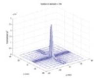
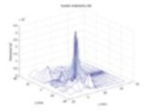
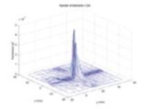
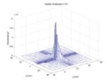
randomness and sparsity into their arrangement (Hutchinson et al. 1996; Goss et al. 1996; Gavrilov et al. 1997; Filonenko et al. 2004; Hand et al. 2009eral movement in the focal plane by distances of ~10 % of the geometric focal length. Pernot et al. (2003) compared the steering capabilities and appearance of side lobes at a frequency of 0.9 MHz for three sparse array geometries (hexagonal, annular and quasi-random), each with 52 % coverage of the 180 mm diameter, 120 mm geometrical focal length spherical surface on which they were mounted. They showed by simulation that the quasi-random design gave the best beam steering capability while maintaining sufficient peak pressure amplitude. Their results were validated by experiment. In Figs. 1.2, 1.3 and 1.4, field simulations for a 256 element random array are displayed, showing the influence
Fig. 1.2 Effect of changing number of elements. 20 cm radius of curvature, 20 cm diameter, 1.7 MHz, 5 cm diameter central aperture
G. ter Haar
20 mm in Y (to source left)
of the beam pattern of the number of array elements (Fig. 1.2), the radius of curvature of the bowl on which they are placed (Fig. 1.3), and the drive frequency (Fig. 1.4).
A disadvantage of the sparse array is that energy is deposited incoherently in the near field (Payne et al. 2011). This leads to a low level of heating that becomes problematic when focal lesions are to be placed side by side (to gain confluent ablation volumes) with their near fields overlapping, since the temperature may rise to biologically significant levels. This is avoided by introducing a cooling time between “shots”, but this in turn lengthens the treatment time. In order to reduce these problems, a 500 kHz flat phased array with elements space λ/2 apart has been proposed (Ellens et al. 2015). While this reduces the effects of near field heating, and avoids the problem of grating lobes, this lower frequency (necessary if the λ/2 separation is to be achieved),
20 mm in Z (away from source)
results in a lower spatial resolution and cavitation threshold, and increases the probability of heating post-focally. At this lower frequency, the ultrasound absorption is reduced, and more acoustic power is required to achieve the desired temperatures than for the 1–3 MHz frequency range that is more commonly used. This illustrates the necessity, common to all designs, of making trade offs and compromises Hill et al. 1994.
It is not possible here to describe in detail the many different transducer geometries available, but Table 1.1 summarizes the many different designs, their steering capabilities, and their advantages and disadvantages.
When tissue targets lie behind the ribcage (such as those in liver, kidney or pancreas) or under the skull, approaches that avoid overheating the bone surface are required if an acoustic window is not to be created by surgical removal of some skull or ribs. For the rib cage, simple ray
Fig. 1.3 aperture
20 mm in Y (to source left) 20 mm in Z (away from source)
tracing may be used to “turn off” elements whose 2006) or, more sophisticatedly, time reversal or adaptive focusing techniques are used (Pernot et al. 2003; Tanter et al. 1998, 2001; Thomas and Fink 1996; 2002a, b; Aubry et al. 2008). Using these techniques, selective regions
lying behind bone can be targeted, and clinically, they have been used successfully in the treatment of essential tremor and other neurological problems (Medel et al. 2012; Martin et al. 2009; Elias et al. 2013). The ultrasound field is severely distorted in amplitude and phase by passage through the skull. Time reversal can correct the phase Freq. (MHz) No steering
Fig. 1.4 Effect of changing frequency. 256 elements, 20 cm radius of curvature, 20 cm diameter, 5 cm diameter central aperture
G. ter Haar
Table 1.1 Summary of available transducer geometries, their advantages and disadvantages
2002 ), Fjeld et al. ( 1999 ), 2012 ), Fry ( 1958 et al. ( 1996 ), ter Haar 2007 ), Melodelima et al. ( 2009 ), Aptel et al. ( 2011 )
aberrations induced by the skull bone, and when combined with amplitude correction, is used to restore the desired focus at the brain target. The time reversal technique relies on the reciprocity property of the wave equation, and requires the presence of a sensor at the anticipated focal point in the brain to record the aberrations, which disrupt the focus. The implantation of such a sensor is clinically unrealistic, but it has been shown that it is possible to perform the required phase and amplitude corrections using either magnetic reso-
images of the skull to model its ultrasonic properties for use in numerical modeling of the wave front distortion (Hynynen and Sun 1999; Aubry et al. 2003). This allows the propagation of a wave front emanating from a virtual point-like source in the brain (the intended “target”) through the skull to be simulated and recorded by a set of virtual receivers outside the head. This wave front can be time reversed, and emitted by a real transducer array. This, along with amplitude correction made possible by knowledge of the porosity of the bone beam at the brain “target” (Aubry et al. 2003).
1.5.1 Transducer Materials
There are a number of constraints that must be considered in the design of a therapy ultrasound
transducer. Apart from the obvious necessity of the ability to produce high powers at frequencies in the range 0.25–10 MHz (requiring high electro-acoustic conversion efficiency), they must be reliable, able to deliver energy in pulsed or continuous wave form, and be physically compatible with the chosen imaging methods.
logical challenge. When ultrasound is the monitoring modality of choice, a central aperture is usually required in the therapy transducer, into which an imaging probe can be inserted. There is increasingly a call for transducer elements that are dual mode, that is, are capable of operating both as therapy sources at high power, and of being used in short pulse, imaging mode (Ebbini et al. 2006; Owen et al. 2010; Mari et al. 2013; 2013).
Multi-element arrays are most commonly constructed in one of two ways. Individual elements can be cased in separate housings and then mounted individually on a shell of the required geometry. This allows easy replacement of failing elements and gives flexibility in their arrangement, but only allows for sparse arrays. An example of such a multi-element array is shown in Fig. 1.5. The alternative is to create an array by, for example, cutting deep grooves into a single piezo-ceramic sheet. This allows for denser packing of the elements, but can create a fragile
Fig. 1.5 Multi-element pseudo-random array composed of 256 individual elements mounted in 3D printed shell
G. ter Haar
array when larger sizes are required. Hybrid combinations of these two methods are also possible.
With few exceptions (most notably for lithotripsy), medical ultrasound transducers are made from piezo-electric materials. Early pioneers in this area used the naturally occurring material, quartz (Fry 1953, 1977; Fry et al. 1954). Piezoelectricity was first discovered by Pierre and
to the property of a crystalline material that develops a charge when it is subjected to mechanical stress. The inverse effect is that when an electrical charge is applied to such a material, it will change its shape. An alternating current applied across a piezo-electric disc will cause rapid movement of its faces, creating a pressure wave in the medium in which it sits. Naturally occurring piezo-electric materials other than quartz include sucrose, tourmaline, lead titanate and dry bone.
In medical ultrasound, the most commonly used piezo-electric material is now lead zirconate xTi1-x]O3
ceramic is cut into discs, the thickness of which determines the resonant frequency, the higher the frequency, the thinner the disc. In order to reduce fragility it is often convenient to drive these transducers at their third harmonic. For high power
monly air backed, to allow cooling and to reduce damping of the pressure wave. While highdensity arrays can be made from simple piezo-electric materials, they operate in a narrow bandwidth, and it is necessary to avoid cross talk between adjacent elements of the array.
An alternative to using the piezo-ceramic crystals on their own is to incorporate them into a 2000).
Here, pillars of piezo-ceramic material are embedded in a polymer. The presence of the polymer enhances the vibration in the thickness mode used to generate the ultrasound wave, and reduces cross talk between the elements. The transducer shell can be shaped, and a solid backing material can be used, rendering the transducer less fragile. A common geometry for piezocomposites used in therapy ultrasound is 1–3. This describes the continuity of the piezo-ceramic
in one dimension (a pillar) and the 3D continuity of the embedding polymer.
Polyvinylidene fluoride (PVDF) is another commonly used piezo-electric material used in medical ultrasound applications. This may be manufactured as a thin (acoustically transparent) membrane, and can be electroded to act as either a sensor or a low power source. PVDF membrane hydrophones are in common use as they only minimally distort the acoustic field during pressure measurement (Shotton et al. 1980; Bacon 1982; Bailey et al. 2011; Wear et al. 2014). -
to be capable of producing sufficient power for HIFU applications, but recent publications indicate that this limitation may be overcome (Wong et al. 2010; Khuri-Yakub and Oralkan 2011; Yamaner et al. 2012; Lee et al. 2013).
1.6
Clinical Devices
The characteristics of transducers currently in clinical use are shown in Table 1.2. This is necessarily not a completely comprehensive list. The aim for most systems is to deliver an in-situ intensity greater than 103 W.cm−2 at the focus. For extra-corporeal sources with long focal length, this is achieved using a high power wide aperture source. Wide aperture sources have the advantage of distributing the incident energy over a large skin area, thus reducing the possibility of skin burn. Trans-rectal and intra-cavitary sources operate at lower powers and higher frequencies as they can be placed close to the target volume.
1.6.1 Extracorporeal Devices
Tissue targets lying within the breast, abdomen, brain or limbs are usually treated using an extracorporeal HIFU source. This necessitates a suitable acoustic window on the skin that allows access to the treatment site that is free of gas or bone in the propagation path. It must also be possible to couple the ultrasound energy to the skin surface using coupling gel, a water balloon or
Table 1.2 Summary of devices currently in use clinically
3 Wu et al. ( 2005a )
Intensity (W.cm −2 )
Acoustic power (W)
Focal length (mm)
Transducer aperture (cm)
DeviceApplicationGuidanceFreq. (MHz)
Liver cancerUS0.8/1.612135–5–20·10
Kidney cancerUS0.8/1.61213.5<300–Illing et al. ( 2005 )
3 Wu et al. ( 2005a , b )
Breast cancerUS1.61290–5–15·10
0.96–1.1412Variable100–140–Tempany et al. ( 2003 )
Biliary duct cancerUS100.3 × 1.0n/a14Prat et al. ( 1999 )
H/HGynaecologyNone5–81.2510–30–Li et al. ( 2004 )
OphthalmologyVisual216 × cylindrical segment, 10.2 mm radius, 4.5 mm width and a 7 mm length 10.22–Aptel et al. ( 2011 )
I/OLiver metastasesUS3Toroid 70 mm70, 86––Dupré et al. ( 2015 )
Breast, thyroidUS3––125–Kovatcheva et al. ( 2014 , 2015 )
E/C extra-corporeal, T/R trans-rectal, H/H hand held, I/O intra-operative, (−) signifies that information in not available
other suitable path of a material of similar acoustic impedance to that of the skin. Extracorporeal HIFU treatments are guided using either US or 2007). When treatments are carried the magnetic compatibility of the treatment head.
levels of electrical excitation and mechanical stress induced. Nickel causes magnetic field distortion, and eddy currents may be set up when the transducers are given a conductive silver coating. These eddy currents may cause local magnetic field inhomogeneities, and significant image artifacts. It is possible to reduce these currents by segmenting the transducer face into a number of areas (Wharton et al. 2007). The piezo-composite materials discussed above reduce these problems, and have been used by the commercial clinical systems now available.
mometry sequences are available that allow temperature mapping in soft tissue. This enables the superimposition of either the temperature, or the calculated thermal dose, on the anatomi-
entire target region can be “painted” out during
guided clinical HIFU systems achieve volume ablation in different ways. Both systems aim to minimize treatment times. In one, the focus is swept electronically in concentric circles, with the user able to choose the maximum diameter of this sweep, and in the other, the phase and amplitude applied to the multi-element array is designed to produce multiple focal peaks in the focal plane.
Where US is used to guide and monitor HIFU treatments, the diagnostic transducer is incorporated into the treatment head. This allows real time imaging of the ablation process. The thermally ablated region is not visible on standard B-mode images in the absence of contrast media, unless gas bubbles have been induced. HIFU exposures levels are therefore often adjusted until a hyperechoic region is seen on the US image, indicating that bubbles are present in this region. These are generated by thermal exsolution of
tissue gas. The stiffness of tissue is altered by the ablation process, and so elastographic techniques should allow treatments to be monitored in real time, although this technique has not yet achieved widespread clinical use.
1.6.2 Trans-rectal Devices
Trans-rectal devices have been developed for the treatment of benign and malignant prostate disease. These have probes that can be inserted per rectum and which incorporate both imaging and therapy transducers in one unit. The clinical acceptance of these devices was made easier by
the diagnostic investigation of choice for many urologists. There are two commercially available devices, which are very similar in concept. In both systems the therapy transducer takes the form of a truncated spherical bowl.
1.6.3 Interstitial Devices
There has been some interest in the development of high intensity ultrasound probes for interstitial use. In the main, these use plane transducers rather than focusing elements, and volume destruction is obtained by rotation of the probe. Prat et al. (1999) have described a probe designed for the intra-ductal treatment of biliary tumors. A 3 × 10 mm 10 MHz plane transducer is mounted on a stainless steel shaft that is passed through a jumbo fiberduodenoscope. The probe can be positioned under fluoroscopic guidance. An ultrasound intensity at the transducer face of 14 Wcm−2 ablation is achieved by rotation of the flexible probe. The transducer is rotated by 18° after each “shot”. Once 360° of damage has been achieved, the probe is repositioned under fluoroscopic guidance to create adjacent rings. This has been used clinically with some encouraging results (Prat et al. 2001 working on similar principles has been created for the treatment of esophageal tumors (Melodelima et al. 2005).
While the main clinical route for the HIFU treatment of the prostate is trans-rectal, the transurethral route has also been explored under ultra2013; Siddiqui et al. 2010). This route reduces the risk of damaging the rectal wall.
1.7 Summary
Modern medicine concentrates on developing personalized treatments and techniques that minimize intervention to the patient and length of hospital stay. HIFU fits excellently into this philosophy. Thermal ablation therapies in general provide a minimally invasive approach to cancer therapy that is gaining rapid clinical acceptance. HIFU is the least invasive of the available ablative techniques, and as such should be the most attractive. However, there remain outstanding technical and treatment delivery questions to be addressed. The growing use of multi-element phased array sources has increased the flexibility of HIFU delivery, and shortened treatment times. Integration of therapy and diagnostic technique has improved treatment targeting and monitoring, thus rendering HIFU both safer and more effective. It seems probable that, as the evidence base for the clinical efficacy of HIFU improves, there will be a move towards more application specific devices, as already seen for treatments in the brain, eye and thyroid.
Acknowledgements I should like to thank my team at
Sinden and Pierre Gelat.
References
future applications of high intensity focused ultra-
Blumen-Ohana E, Denis P (2011) Miniaturized highintensity focused ultrasound device in patients with glaucoma: a clinical pilot study. Investig Ophthalmol Vis Sci 52:8747–8753
tory open-angle glaucoma using ultrasonic circular
Aubry JF, Pernot M, Marquet F, Tanter M, Fink M (2008) Transcostal high-intensity-focused ultrasound: ex vivo adaptive focusing feasibility study. Phys Med Biol 53:2937–2951
Aubry JF, Tanter M, Pernot M, Thomas JL, Fink M (2003) Experimental demonstration of noninvasive transskull adaptive focusing based on prior computed tomography scans. J Acoust Soc Am 113:84–93 ‐‐
intensity focused ultrasound (HIFU) in unilateral radiorecurrent prostate cancer: a prospective two‐centre study. BJU Int 114:532–540
hydrophone for use in the range 1–100 MHz. IEEE Trans Sonics Ultrasonics 29:18–25
OA (2011) Polyvinylidene fluoride membrane hydrophone low‐frequency response to medical shockwaves. J Acoust Soc Am 129:2677–2677
Ballantine HT, Bell E, Manlapaz J (1960) Progress and problems in the neurological application of focused ultrasound. J Neurosurg 17:858–876
implementation of a dual-mode ultrasound array system: in vivo results. IEEE Trans Biomed Eng 60: 2751–2759
(2002) An image-guided high intensity focused ultrasound device for uterine fibroids treatment. Med Phys 29:2611–2620
JU, Sapozhnikov OA, Guey JL (2000) New piezoelectric transducers for therapeutic ultrasound. Ultrasound Med Biol 26:153–159
and side effects of high-intensity focused ultrasound in localized prostate cancer. J Endourol 15:437–440
(2002) High intensity focused ultrasound in the treatcavitation dose and hemolysis produced in vitro with or without Optison®. Ultrasound Med Biol 29:725–737 -
sound ablation: a new strategy to manage primary
H, Shung KK (2012) Design and characterization of dual-curvature 1.5-dimensional high-intensity focused ultrasound phased-array transducer. IEEE Trans
use of a segmented transducer for rib sparing in HIFU treatments. Ultrasound Med Biol 32:1753–1761
G. ter Haar
transcranial beam steering. IEEE Trans Ultrason
for focusing ultrasound through the skull. Phys Med Biol 47:1219–1236
LA (1980) Ultrasonically accelerated absorption of vitreous membranes. Am J Ophthalmol 89:490–499
(2004) Heating of biological tissues by twodimensional phased arrays with random and regular element distributions. Acoust Phys 50:222–231 for ultrasound surgery. Phys Med Biol 44:1803–1813
Muenkler J, Kamp MH, Maurer A, Beck A, Hamm B, Kroencke TJ (2013) Outcome of uterine artery embo-
ultrasound treatment for uterine fibroids: long-term
Fry WJ (1953) Action of ultrasound on nerve tissue—a review. J Acoust Soc Am 25:1–5
Fry FJ (1958) Precision high intensity focused ultrasonic machines for surgery. Am J Phys Med 37:152–156
Ophthalmol 92:347–353
planar rectangular high intensity ultrasound trans(2015) Focal High-Intensity Focused Ultrasound (HIFU). In: Technical aspects of focal therapy in localized prostate cancer. Springer, Paris, pp 137–151
intensity focused ultrasound as focal therapy of pros-
phased array system for the treatment of large volumes of deep seated tissue. IEEE Trans Ultrason Ferroelectr
cal outcomes following whole gland primary HIFU from the UK independent HIFU registry. J Urol 189, e227
Duck FA (2013) Physical properties of tissues: a comprehensive reference book. Academic press, London
arrays used in focused ultrasound surgery. IEEE Trans
ence of intra-operative high intensity focused ultrasound in patients with colorectal liver metastases: a phase I-IIa study. PLoS One 10, e0118212
Ebbini ES, Yao H, Shrestha A (2006) Dual-mode ultrasound phased arrays for image-guided surgery. Ultrason Imaging 28:65–82
Druzgal J, Shah BB, Harrison M, Wintermark M (2013) A pilot study of focused ultrasound thalamotomy for essential tremor. N Engl J Med 369:640–648
KH (2015) A novel, flat, electronically-steered phased array transducer for tissue ablation:preliminary results. Phys Med Biol 60:2195–2215
Fry FJ (1977) Transkull transmission of an intense focused ultrasonic beam. Ultrasound Med Biol 3:179–189
Fry WJ, Mosberg WH, Barnard JW, Fry FJ (1954) Production of focal destructive lesions in the central nervous system with ultrasound. J Neurosurg 11: 471–478
Fry FJ, Ades HW, Fry WJ (1958) Production of reversible changes in the central nervous system by ultrasound. Science 127:83–84
Fry WJ, Fry FJ (1960) Fundamental neurological research and human neurosurgery using intense ultrasound.
arrays for surgery: movement of a single focus. Acoust Phys 46:390–399 of reducing grating lobes associated with an ultrasound linear phased array intended for transrectal thermotherapy. IEEE Trans Ultrason Ferroelectr Freq
dimensional phased arrays for application in surgery: scanning by several focuses. Acoust Phys 46:551–558
ultrasound experimentation on human benign prostatic hypertrophy. Eur Urol 23:44–47
Gelet A et al (2004) Local recurrence of prostate cancer after external beam radiotherapy: early experience of salvage therapy using high-intensity focused ultrasonography. Urology 63:625–629
empirical ultrasonic properties of mammalian tissues. II. J Acoust Soc Am 68:93–108
Goss SA, Frizell LA, Kouzmanoff JT, Barich JM, Yang JM (1996) Sparse random ultrasound phased array for focal surgery. IEEE Trans Ultrason Ferroelectr Freq
ples & devices. Int J Hyperthermia 23:89–104
ter Haar G (2010) Ultrasound bioeffects and safety. Proc Inst Mech Eng H 224:363–373
ter Haar G, Shaw A, Pye S, Ward B, Bottomley F, Nolan
sound exposure conditions for bioeffects studies. Ultrasound Med Biol 37:177–183
delivery of high intensity focused ultrasound. Phys Med Biol 54:5675–5693
focused ultrasound for the treatment of uterine
Lesion development in focused ultrasound surgery: a general model. Ultrasound Med Biol 20:259–269
enhanced heating from focused, MHz-frequency ultrasound in a tissue-mimicking material. Ultrasound Med Biol 27:1399–1412
and endothelial cell damage in vivo. Ultrasound Med Biol 32:1611–1619
Hurwitz MD, Ghanouni P, Kanaev SV, Iozeffi D, Gianfelice D, Fennessy FM, Kuten A, Meyer JE,
(2014) Magnetic resonance-guided focused ultrasound for patients with painful bone metastases: phase
Hutchinson EB, Buchanan MT, Hynynen K (1996) Design and optimization of an aperiodic ultrasound phased array for intracavitary prostate thermal therapies. Med Phys 23:767–776
noninvasive surgery. IEEE Trans Ultrason Ferroelectr
Hynynen K, Sun J (1999) Transskull ultrasound therapy: The feasibility of using image derived skull thickness information to correct the phase distortion. IEEE
extracorporeal high-intensity focused ultrasound (HIFU) for the treatment of liver and kidney tumours
propagation, cavitation, and boiling in lesion formation by high intensity focused ultrasound in a gel phantom. J Acoust Soc Am 119:1834–1848
chined ultrasonic transducers for medical imaging and therapy. J Micromech Microeng 21:054004
ultrasound as a promising non-invasive method for 24:2052–2058
G. ter Haar
Laurent N, Poncelet E (2015) Ultrasound-guided highintensity focused ultrasound treatment of breast fibroadenoma—a multicenter experience. J Ther Ultrasound 3:1
sound applicator for endoscopic procedures: animal experimentation. Ultrasound Med Biol 26:669–675
Thaler W (1952) Effects of ultrasonic waves on the refractive media of the eye. Arch Ophthalmol 47:204–209
embedded springs. In: Proceeding IEEE Ultrasonics
Focused ultrasound therapy of vulvar dystrophies: a feasibility study. Obstet Gynecol 104:915–921
Noninvasive treatment of malignant bone tumors using high‐3934–3942
palliation in patients with bone metastases using study. Ann Surg Oncol 16:140–146
FA (1978) Experimental ultrasonically induced lesions in the retina, choroid, and sclera. Invest Ophthalmol 17:350–360
method for the generation and use of focused ultrasound in experimental biology. J Gen Physiol 26:179–192
thermal dosimetry during focused ultrasound thermal
Madersbacher S, Schatzl G, Djavan B, Stulnig T, Marberger M (2000) Long-term outcome of transrectal high- intensity focused ultrasound therapy for benign prostatic hyperplasia. Eur Urol 37:687–694
Mari JM, Bouchoux G, Dillenseger JL, Gimonet S, Birer
(2013) Study of a dual-mode array integrated in a multi-element transducer for imaging and therapy of
(2009) High-intensity focused ultrasound for noninvasive functional neurosurgery. Ann Neurol 66:858–861
Sheehan JP, Wintermark M, Jolesz FA, Kassell NF (2012) Magnetic resonance guided focused ultrasound surgery: part 2 – a review of current and future applications. Neurosurgery 71:755–763
cator for sector-based thermal ablation: first in vivo experiments. Ultrasound Med Biol 29:285–291
intensity ultrasound treatment in the esophagus under
high-intensity-focused ultrasound using a toroid trans-mal experiments. Ultrasound Med Biol 35:425–435
focused ultrasound ablation: a new therapeutic optionsound imaging and thermal therapy. Ultrasonics 50:216–220
Parker DL (2011) The effect of electronically steering a phased array ultrasound transducer on nearfield tissue heating. Med Phys 38:4971–4981
Pernot M, Aubry JF, Tanter M, Thomas JL, Fink M (2003) High power transcranial beam steering for ultrasonic brain therapy. Phys Med Biol 48:2577–2589
probe designed for intraductal tumor destruction: experimental results. Gastrointest Endosc 50:388–392
carcinoma by intraductal high intensity ultrasound
Quinn SD, Gedroye WM (2015) Thermal ablation treatment of uterine fibroids. Int J Hyperthermia 31: 272–279
focused ultrasound surgery transducers. IEEE Trans
monitoring and thermometry for therapeutic focused ultrasound. Int J Hyperthermia 23:121–139
radiation on the ciliary body. Am J Ophthalmol 63: 403–409
(1999) Noninvasive surgery of prostate tissue by high intensity focused ultrasound: an updated report. Eur J Ultrasound 9:19–29
10:787–800
membrane hydrophone for operation in the range 0.5 MHz to 15 MHz. Ultrasonics 18:123–126
therapy of the prostate gland using real-time thermal mapping: initial studies. Urology 76:1506–1511
(1991) Therapeutic ultrasound for the treatment of glaucoma. Am J Ophthalmol 111:327–337
Sommer G, Pauly KB, Holbrook A, Plata J, Daniel B,
48:387–394
Sullivan LD, McLoughlin MG, Goldenberg LG, Gleave ME, Marich KW (1997) Early experience with highintensity focused ultrasound for the treatment of benign prostatic hypertrophy. Br J Urol 79:172–176
Tanter M, Thomas JL, Fink M (1998) Focusing and steering through absorbing and aberrating layers: application to ultrasonic propagation through the skull. J Acoust Soc Am 103:2403–2410
Tanter M, Aubry JF, Gerber J, Thomas JL, Fink M (2001) Optimal focusing by spatio-temporal inverse filter: part I. Basic principles. J Acoust Soc Am 101:37–47
focused ultrasound surgery of uterine leiomyomas:
Thomas JL, Fink M (1996) Ultrasonic beam focusing through tissue inhomogeneities with a time reversal mirror: application to transskull therapy. IEEE Trans
ablation by robotic High-Intensity Focused Ultrasound (HIFU) at 3 MHz: 18 years clinical experiences. In: Focal therapy of prostate cancer, Springer International Publishing, Switzerland, pp 105–133 ‐
gland salvage high‐intensity focused ultrasound therapy for localized prostate cancer recurrence after external
Alizad A (2013) A beamforming study for implementation of vibro-acoustography with a 1.75-D array trans60:535–551
Valerio M, Ahmed HU, Emberton M, Lawrentschuk N, of focal therapy in the management of localised prostate cancer: a systematic review. Eur Urol 66:732–751
a toroidal HIFU transducer substantially increases the coagulated volume. Ultrasound Med Biol 39:1241–1254
Wear K, Gammell P, Maruvada S, Liu Y, Harris G (2014) Improved measurement of acoustic output using complex deconvolution of hydrophone sensitivity. IEEE -
sonic transducers for therapeutic ultrasound applications. IEEE Trans Biomed Eng 57:114–123
development of a prototype endocavitary probe for high‐intensity focused ultrasound delivery with inte-
Imaging 25:548–556
ultrasound ablation in the treatment of 1038 patients
Sonochem 11:149–154
hepatocellular carcinoma: treatment with highintensity focused ultrasound ablation combined with 659–667
US-guided high-intensity focused ultrasound treatment in patients with advanced pancreatic cancer: ini-
Yamaner FY, Olcum S, Oguz HK, Bozkurt A, Koymen H, experimental verification. IEEE Trans Ultrason
G. ter Haar
J.-Y. Chapelon (*)
Prostate Focused Ultrasound Therapy
Jean-Yves Chapelon, Olivier Rouvière, Sébastien Crouzet, and Albert Gelet
Abstract
The tremendous progress in engineering and computing power coupled with ultrasound transducer technology and imaging modalities over the past 20 years have encouraged a revival of clinical interest in ultrasound therapy, mainly in High-Intensity Focused Ultrasound (HIFU). So far, the most extensive results from HIFU obtained in urology involve transrectal prostate ablation, which appears to be an effective therapeutic alternative for patients with malignant prostate tumors. Prostate cancer (PCa) is one of the most frequently diagnosed cancers in men. Several treatment options with different therapeutic approaches exist, including HIFU for localized PCa that has been in use for over 15 years. Since the early 2000s, two systems have been marketed for this application, and other devices are currently in clinical trials. HIFU treatment can be used either alone or in combination with (before- or after-) external beam radiotherapy (EBRT) (before or after HIFU) and can be repeated multiple times. HIFU treatment is performed under real-time monitoring with ultrasound or guided by MRI. Two indications are validated today: Primary care treatment and EBRT failure. The results of HIFU for primary care treatment are similar to standard conformal EBRT, even though no randomized comparative studies have been performed and no 10-year follow up data is yet available
INSERM, U1032, Lyon F-69003, France
Laboratory of Therapeutic Applications of Ultrasound, Université Lyon 1, Lyon, France
e-mail: jean-yves.chapelon@inserm.fr
O. Rouvière
INSERM, U1032, Lyon F-69003, France
Laboratory of Therapeutic Applications of Ultrasound, Université Lyon 1, Lyon, France
Department of Radiology, Hospices Civils de Lyon, Edouard Herriot Hospital, Lyon, France
S. Crouzet • A. Gelet
INSERM, U1032, Lyon F-69003, France
Laboratory of Therapeutic Applications of Ultrasound, Université Lyon 1, Lyon, France
Department of Urology, Hospices Civils de Lyon, Edouard Herriot Hospital, Lyon, France
J.-M. Escoffre, A. Bouakaz (eds.), Therapeutic Ultrasound, Advances in Experimental Medicine and Biology, Vol. 880, DOI 10.1007/978-3-319-22536-4_2
Another random document with no related content on Scribd:
Alexandre.
dangereuse, s'il avait eu un ennemi plus courageux. Résolu d'aller attaquer Constantin, sous prétexte de venger la mort de son père, qu'il ne regrettait pas, mais en effet pour s'enrichir des dépouilles d'un prince qu'il haïssait, il avait dessein de marcher en Rhétie, d'où il pourrait également se porter en Gaule et en Illyrie: il se flattait de s'emparer d'abord de cette dernière province et de la Dalmatie, à l'aide des troupes et des généraux qu'il tenait sur la frontière, et de se jeter ensuite dans la Gaule, dont il se rendrait aisément le maître. Mais avant que d'en venir à l'exécution de ces chimériques projets, il crut devoir s'assurer de l'Afrique, où Alexandre se maintenait depuis trois ans. Ce tyran y avait étendu sa puissance, et il paraît qu'il avait ruiné la ville de Cirtha, capitale de la Numidie. Maxence assembla donc un petit nombre de cohortes; il mit à leur tête Rufius-Volusianus, son préfet du prétoire, et Zénas, capitaine renommé pour sa science militaire, et chéri des troupes pour sa probité et sa douceur. Il ne leur en coûta que la peine de passer la mer. Alexandre cassé de vieillesse, et qui n'avait pas plus de capacité que de force, traînant après lui des soldats levés à la hâte et dont la moitié étaient sans armes, vint à leur rencontre: mais ce ne fut que pour prendre la fuite dès le premier choc. A peine quelques bataillons firent-ils une faible résistance, tout fut renversé en un moment; il fut lui-même pris et étranglé sur-le-champ. On a cru pendant quelque temps que Nigrinianus, dont on a deux médailles qui lui donnent le titre de Divus, était le fils de cet Alexandre, mort avant son père et mis au rang des dieux. Mais on a depuis reconnu que ces médailles ont été frappées entre le règne de Claude second et celui de Dioclétien[13] . [13] Nigrinianus est un de ces personnages impériaux, dont la puissance éphémère est échappée à l'histoire, et dont les médailles seules ont conservé le souvenir. On est réduit à des conjectures pour déterminer l'époque où ils vécurent; mais comme les raisons sur lesquelles on se fonde laissent toujours une certaine
Zos. l. 2, c. 12 et 14.
Aurel. Vict. de Cæs., p. 174 et 175.
�������. Défaite d'Alexandre.
Till. art. 16.
Génebrier, Dissert. sur Nigrinianus. [Eckhel, doct. num. vet. t. ���, p. 520].
latitude, on ne saurait prendre pour constant ce que Lebeau dit ici de Nigrinianus. Le savant Eckhel place aussi ce personnage avant Dioclétien. S.-M.
La guerre était finie, mais les suites de la victoire furent plus funestes que la guerre. Maxence avait ordonné de saccager et de brûler Carthage, qui était redevenue une des plus florissantes villes du monde; d'enlever ou de détruire tout ce qu'il y avait de beau dans la province, et d'en transporter à Rome tous les blés. Les habitants de l'Afrique souffrirent les dernières rigueurs. De ceux qui étaient remarquables par la noblesse ou par les richesses, nul ne fut épargné: tous furent traînés devant les tribunaux, comme ayant été partisans d'Alexandre; tous furent dépouillés de leurs biens: plusieurs perdirent la vie; et après ces violences Maxence triompha dans Rome, beaucoup moins des ennemis vaincus, que de ses malheureux sujets qu'il avait ruinés.
�����.
Désolation de l'Afrique.
Incerti Pan. c. 16. [Zos. l. 2. c. 14].
����. Massacre dans Rome.
Il ne traitait pas les Romains avec plus d'humanité. Dès avant la guerre d'Afrique, le feu ayant pris au temple de la Fortune à Rome, comme on s'empressait de l'éteindre un soldat laissa échapper un mot de raillerie sur la déesse: le peuple indigné se jette sur lui et le met en pièces. Aussitôt les soldats, et surtout les prétoriens fondent sur le peuple; ils frappent, ils massacrent, ils égorgent sans distinction d'âge ni de sexe; Rome nageait dans le sang, et cette sanglante querelle pensa détruire la capitale de l'empire. Selon Zosime, Maxence apaisa les soldats; selon Eusèbe, il abandonna le peuple à leur fureur: ces deux témoignages se balancent; mais celui d'Aurélius-Victor décide en faveur d'Eusèbe, et rend Maxence coupable du meurtre de ses sujets.
Eus. Hist. eccl. l. 8, c. 14, et Vit. Const. l. 1, c. 35.
Zos. l. 2, c. 13.
Aurel. Vict. de Cæs. p. 175.
Devenu plus insolent, il ne mit plus de bornes à ses rapines, à ses débauches, à ses cruelles superstitions. Il obligeait tous les ordres, depuis les sénateurs jusqu'aux laboureurs, de lui donner par forme de présent des sommes considérables: institution odieuse, mais attrayante pour des successeurs, qui semble perdre de sa bassesse à proportion qu'elle s'éloigne de son origine, et dont les empereurs suivants crurent pouvoir profiter sans en partager la honte.
Non content de cette contribution, qui n'était volontaire qu'en apparence, il fit mourir sous de faux prétextes un grand nombre de sénateurs, pour s'emparer de leurs biens. Il regardait comme son patrimoine celui de tous ses sujets; il n'épargnait pas même les temples de ses dieux: c'était un abîme qui engloutissait toutes les richesses de l'univers, que près de onze siècles avaient accumulées dans Rome: l'Italie était remplie de délateurs et d'assassins dévoués à ses fureurs, et qu'il repaissait d'une part de sa proie:
�����. Avarice de Maxence.
Aurel. Vict. de Cæs. p. 175.
������ Ses rapines.
Euseb vit Const l 1, c 35. Incert. Pan. c. 3 et 4.
une parole, un geste innocent, décelaient un complot contre le prince; un soupir passait pour un regret de la liberté. Cette tyrannie faisait déserter les villes et les campagnes: on cherchait les retraites les plus profondes; les terres demeuraient sans semence et sans culture; et la famine fut si grande, qu'on ne se souvenait point à Rome d'en avoir éprouvé de semblable.
Nazar Pan c 8
Hist Misc l 11, apud Muratori, t �, p 71
Le tyran semblait triompher de la misère publique. Il affectait de paraître heureux, puissant, audessus de toute crainte: il assemblait quelquefois ses soldats pour leur dire, qu'il était le seul empereur; que les autres qui prenaient cette qualité, n'étaient que ses lieutenants qui gardaient ses frontières: pour vous, leur disait-il, jouissez, dissipez, prodiguez: c'était là toute sa harangue. Quoiqu'il feignît d'être occupé de grands projets de guerre, il passait ses jours dans l'ombre et dans les délices: tous ses voyages, toutes ses expéditions se bornaient à se faire transporter de son palais aux jardins de Salluste. Endormi dans le sein de la mollesse, il ne se réveillait que pour se livrer aux excès de la débauche: il enlevait les femmes à leurs maris, pour les leur renvoyer déshonorées, ou les livrer à ses satellites: il n'épargnait pas l'honneur même des premiers du sénat; faire cet outrage à la principale noblesse, c'était pour lui un raffinement de volupté: insatiable dans ses infâmes désirs, sa passion changeait sans cesse d'objet, sans se fixer ni s'éteindre: les prisons étaient remplies de pères et de maris, qu'une plainte, un gémissement, avaient rendus dignes de mort.
�������. Ses débauches.
Incert. Pan. c. 14 et c. 3.
Euseb. vit. Const., l. 1, c. 33 et 34.
Prud. in Symm. l. 1, v. 470.
Hist. Misc. l. 11, apud Muratori, t. �, p. 71.
Mais ni ses artifices ni ses menaces ne triomphaient de la chasteté des femmes chrétiennes, parce qu'elles savaient mépriser la vie. On raconte qu'une d'entre elles, nommée Sophronie, épouse du préfet de la ville, ayant appris que les
������ Mort de Sophronie
Euseb Hist ecc l 8, c 14
ministres des débauches du tyran la venaient chercher de sa part, et que son mari par crainte et par faiblesse la leur avait abandonnée, elle leur fit demander quelques moments pour se parer, et que l'ayant obtenu, seule et retirée dans son appartement, après une courte prière elle se plongea un poignard dans le sein, et ne laissa à ces misérables que son corps sans vie. Plusieurs auteurs ecclésiastiques louent cette action; elle ne porte cependant pas le sceau de l'approbation de l'église, qui n'a pas mis cette femme au nombre des saintes. Les païens devaient admirer cette chasteté héroïque, et la mettre fort audessus de celle de Lucrèce.
Rufin l 8, c 17
�����.
Superstitions de Maxence.
Euseb. vit.
Const., l. 1, c. 36.
Quoique Maxence affectât une entière sécurité, il craignait Constantin; et ne pouvant se dissimuler qu'il ne trouvait pas en lui-même assez de ressources, il en chercha dans la magie. Pour se rendre les démons favorables, et pour pénétrer dans les secrets de l'avenir, il faisait ouvrir le ventre à des femmes enceintes, fouiller dans les entrailles des enfants tirés de leur sein. On égorgeait des lions; et par des sacrifices et des formules de prières abominables il se flattait d'évoquer les puissances de l'enfer, et de détourner les malheurs dont il était menacé.
Mais il avait en tête un ennemi plus puissant que ses dieux. Constantin, soit de son propre mouvement, comme le dit Eusèbe, soit qu'il en fût secrètement sollicité par les habitants de Rome, comme le rapportent d'autres auteurs, songeait à délivrer cette ville de l'oppression sous laquelle elle gémissait; et les projets d'un prince plein de prudence et d'activité étaient plus sûrs et mieux concertés que ceux de Maxence. Pour ne laisser derrière lui aucun sujet d'inquiétude, il visita, au commencement de cette année, toute la partie de la Gaule voisine du Rhin et des Barbares. Il assura
������. Constantin se prépare à la guerre.
Euseb. vit. Const. l. 1, c. 26.
Incert. Pan. c. 2 et 3.
Cedren t �, p 270
cette frontière par des flottes sur le fleuve, et par des corps de troupes qui servaient de barrière. Il s'avança jusqu'à Autun [Augustodunum]. Cette ville signalée par son zèle pour Rome dès avant le temps de Jule-César, dont les peuples avaient reçu du sénat le nom de Frères du peuple romain, fameuse par ses écoles publiques, presque détruite par Tétricus sous l'empire de Claude II, relevée par les successeurs de ce prince, honorée depuis peu des bienfaits de Constance Chlore, était alors réduite à une misère déplorable. Quoique son territoire ne fût pas plus chargé de tailles que le reste de la Gaule, toutefois les ravages des guerres passées ayant détruit toute culture, et ruiné un terrain naturellement assez ingrat, elle était hors d'état de supporter sa part de l'imposition générale. Le découragement des laboureurs rendait le mal irrémédiable. Comme leur travail ne pouvait fournir à la fois au paiement des tailles et à leur nourriture, ils avaient pris le parti de mourir de faim sans travailler. Les moins abattus par le désespoir se retiraient dans les bois ou désertaient le pays. Lorsque Constantin entra dans la ville, qu'il croyait trouver abandonnée, il fut étonné de la multitude de peuple qui s'empressait à le voir et à lui témoigner sa joie. A la nouvelle de son approche, on était accouru en foule de tout le voisinage; on avait paré les rues jusqu'au palais, de tout ce que la misère peut appeler des ornements: toutes les compagnies sous leur drapeau, tous les prêtres avec les statues de leurs dieux, tous les instruments de musique honoraient son arrivée. Le sénat de la ville se prosterna à ses pieds à la porte du palais dans un profond silence: l'empereur versant des larmes de pitié et de tendresse, tendit la main aux sénateurs, les releva, prévint leur demande, leur remit le tribut de cinq années qu'ils devaient au trésor; sur les vingtcinq mille taillables du territoire d'Autun, il fit grace pour l'avenir de sept mille capitaux[14] Cette faveur fit renaître l'espoir et l'industrie: Autun se repeupla, les terres furent mises en valeur; la ville regardant Constantin comme son père et son fondateur, prit le nom
Zonar l 13, t 2, p 2
������� Il
soulage la ville d'Autun
Eumen Grat Act passim
de Flavia; et le prince retourna à Trèves, triomphant dans le cœur des peuples; et plus glorieux d'avoir rendu la vie à vingt-cinq mille familles, que s'il eût terrassé la plus nombreuse armée.
[14] Septem millia capitum remisisti, dit Euménius, dans le Panégyrique d'actions de grace, qu'il prononça pour remercier Constantin au nom de ses concitoyens, § �� S -M
Il trouva à Trèves un grand nombre d'habitants de presque toutes les autres villes de ses états, qui venaient honorer la célébration de sa cinquième année, et lui demander des graces, soit pour leur pays, soit pour leurs propres personnes. Il renvoya satisfaits ceux même à qui il ne pouvait accorder leurs demandes. Ce fut en présence du prince et au milieu de cette nombreuse assemblée, qu'Euménius établi, par Constance Chlore, chef des études d'Autun, avec une pension de plus de soixante mille livres[15] , prononça un discours de remercîment que nous avons encore, pour les bienfaits dont l'empereur avait comblé sa patrie.
�������� Il retourne à Trèves Eumen grat act c 2 et pro rest schol c 11 et 14
[15] Salarium me liberalissimi principes, ex hujus reipublicæ viribus in sexcenis millibus nummum accipere jusserunt. Eumenius, Orat. pro restaur. scholis, § ��.— S.-M.
Tout se disposait à la guerre. Constantin balançait encore; il craignait qu'elle ne fût pas assez juste. Auprès des autres souverains la justice n'était qu'une couleur, qu'ils comptaient bien que la victoire ne manquerait pas de donner à leurs entreprises: pour Constantin c'était un motif sans lequel il ne se croyait en droit de rien entreprendre. Malgré la compassion qu'il avait de la ville de Rome, malgré les cris de ceux qui l'appelaient, il doutait, avec raison, qu'il lui fût permis de détrôner un prince qui n'était pas son vassal, quoiqu'il abusât de son pouvoir. Il prit donc les voies de douceur: il envoya proposer à Maxence une entrevue. Celui-ci loin de l'accepter, entra dans une espèce de fureur; il fit abattre ce qu'il y avait à Rome de
������ Outrage qu'il reçoit de Maxence.
Nazar. Pan. c. 9 et seq.
Lact. de mort. persec. c. 43.
statues de Constantin, et les fit traîner dans la boue: c'était une déclaration de guerre; et Maxence, en effet, publia qu'il allait venger la mort de son père.
Licinius pouvait traverser Constantin et jeter des troupes en Italie par l'Istrie et par le Norique, qui confinaient avec ses états. Constantin réussit à se l'attacher en lui promettant sa sœur Constantia en mariage. Maximin prit ombrage de cette promesse; il crut que cette alliance se formait contre lui: et pour la balancer, il s'appuya de celle de Maxence, à qui il envoya demander son amitié, mais secrètement; car il voulait conserver avec Constantin les dehors d'une bonne intelligence. Ses offres furent acceptées avec la même joie qu'un secours envoyé du ciel: Maxence lui fit dresser des statues à côté des siennes. Cependant Constantin ne fut instruit de cette intrigue et de la perfidie de Maximin, que par la vue même de ces statues, quand il fut maître de Rome. Au reste ces deux alliances ne produisirent d'autre effet que la neutralité des deux princes, qui ne prirent aucune part à cette guerre.
Jamais l'Occident n'avait mis sur pied de si nombreuses armées. Maxence assembla cent soixante et dix mille hommes d'infanterie, et dixhuit mille chevaux. C'étaient des soldats qui avaient autrefois servi son père; Maxence les avait enlevés à Sévère, et il y avait joint de nouvelles levées. Les troupes de Rome et d'Italie faisaient quatre-vingt mille hommes; Carthage en avait fourni quarante mille: tous les habitants des côtes maritimes de la Toscane s'étaient enrôlés et formaient à part un corps considérable: le reste était des Siciliens et des Maures. Il employa une partie de ces troupes à garnir les places qui pouvaient défendre l'entrée de l'Italie, et tint la
��. Ils s'appuient tous deux par des alliances.
Lact. de mort. persec. c. 43 et 44.
Euseb. Hist. eccl. l. 8, c. 14.
Incert. Pan. c. 2.
Zos. l. 2, c. 15.
��� Préparatifs de Maxence
Lact de mort persec c 44
Zos l 2, c 15
[Euseb Hist ecc l 9, c 9 ]
Incert Pan c 3
campagne par ses généraux avec cent mille hommes. Il avait des chefs expérimentés, de l'argent et des vivres: Rome en avait été pourvue pour long-temps aux dépens de l'Afrique et des îles, dont on avait enlevé tous les blés. Sa principale confiance était dans les soldats prétoriens, qui l'ayant élevé à l'empire, s'étaient prêtés à toutes ses violences, et ne pouvaient espérer de grace que d'un prince, dont ils avaient partagé tous les crimes.
Constantin avait une armée de quatre-vingt-dix mille hommes de pied et de huit mille chevaux. Elle était composée de Germains, de Bretons et de Gaulois. Mais la nécessité où il était de border le Rhin de soldats pour la sûreté de la Gaule, ne lui laissa que vingt-cinq mille hommes à conduire audelà des Alpes. Un mot qui ne se trouve que dans un panégyriste[16] , suppose qu'il avait une flotte avec laquelle il s'empara de plusieurs ports en Italie. Mais on ne sait sur ce point aucun détail.
���� Forces de Constantin
Incert Pan c 2, 3, 5, 25
Zos l 2, c 15
[16] Ille Oceanum classe transmisit, tu et Alpes gradu, et classibus portus Italicos occupasti. Incert. Paneg. § 25. S.-M.
C'était peu de troupes contre des forces aussi grandes que celles de Maxence: mais au nombre suppléait une bravoure éprouvée, et la capacité de leur chef, qui ne les avait jamais ramenées du combat qu'avec la victoire. Il y eut pourtant d'abord quelques murmures dans l'armée; les officiers même semblaient intimidés et blâmaient sourdement une entreprise qui paraissait téméraire; les haruspices ne promettaient rien d'heureux; et Constantin, qui n'était pas encore affranchi des superstitions, redoutait non pas les armes de son ennemi, mais les maléfices et les secrets magiques qu'il mettait en œuvre.
�����. Inquiétudes de ce prince.
Incert. Pan. ibid.
Euseb. vit.
Const. l. 1, c. 37.
Hist. Misc. l. 11, apud Muratori, t. �, p. 7.
Il crut devoir y opposer de son côté un secours plus puissant; et l'enfer étant déclaré pour Maxence, il chercha dans le ciel un appui supérieur à toutes les
���� Réflexions qui le portent au christianisme
Euseb Vit
Const l 1, c 27.
forces des hommes et des démons. Il fit réflexion qu'entre les empereurs précédents, ceux qui avaient mis leur confiance dans la multitude des dieux, et qui, avec le tribut de tant de victimes et d'offrandes, leur avaient encore sacrifié tant de chrétiens, n'en avaient reçu d'autre récompense, que des oracles trompeurs et une mort funeste; qu'ils avaient disparu de dessus la terre, sans laisser de postérité ni aucune trace de leur passage; que Sévère et Galérius, soutenus de tant de soldats et de tant de dieux, avaient terminé leur entreprise contre Maxence l'un par une mort cruelle, l'autre par une fuite honteuse; que son père seul, favorable aux chrétiens, et plus zélé pour la conservation de ses sujets que pour le culte de ces dieux meurtriers, avait couronné par une fin heureuse une vie tranquille et pleine de gloire. Occupé de ces pensées, qui ne lui donnaient que du mépris pour ses divinités, il invoquait ce Dieu unique, que les chrétiens adoraient, et qu'il ne connaissait pas; il le priait avec ardeur de l'éclairer de sa lumière et de l'aider de son secours.
Un jour que, pénétré de ces sentiments, il marchait à la tête de ses troupes, un peu après l'heure de midi, par un temps calme et serein, comme il levait souvent les yeux vers le ciel, il aperçut au-dessus du soleil du côté de l'orient, une croix éclatante, autour de laquelle étaient tracés en caractères de lumière ces trois mots latins: In hoc vince: vainquez par ceci. Ce prodige frappa les yeux et les esprits de toute l'armée. L'empereur n'était pas encore sorti de son étonnement, lorsque la nuit étant venue il vit en songe le fils de Dieu, qui tenait en main ce signe dont il venait de voir la figure dans le ciel, et qui lui ordonna d'en faire faire un semblable, et de s'en servir comme d'une enseigne dans les batailles.
���. Apparition de la croix
Euseb. vit.
Const l 1, c 29
Socr. l. 1, c. 2.
Philost. l. 1, c. 6
Politia SS.
Le prince à son réveil assemble ses amis, leur raconte ce qu'il vient de voir et d'entendre, mande des ouvriers, leur
dépeint la forme de ce signe céleste, et leur commande d'en faire un pareil d'or et de pierreries. Eusèbe, qui atteste l'avoir vu plusieurs fois, le décrit ainsi: c'était une longue pique revêtue d'or, ayant une traverse en forme de croix: au haut de la pique s'élevait une couronne d'or enrichie de pierreries, qui enfermait le monogramme de Christ, que l'empereur voulut aussi dans la suite porter gravé sur son casque. De la traverse pendait une pièce d'étoffe de pourpre, quarrée, couverte d'une broderie d'or et de pierres précieuses, dont l'éclat éblouissait les regards. Au-dessous de la couronne, mais au-dessus du drapeau était le buste de l'empereur et de ses enfants représentés en or; soit que ces images fussent placées sur la traverse de la croix, soit qu'elles fussent brodées sur la partie supérieure du drapeau même; car l'expression d'Eusèbe ne donne pas une idée nette de cette position. Il semble même, à l'inspection de plusieurs médailles, que ces images étaient quelquefois dans des médaillons le long du bois de la pique, et que le monogramme de Christ était brodé sur le drapeau.
Ce fut dans la suite le principal étendard de l'armée de Constantin et de ses successeurs. On l'appela Labarum ou Laborum Le nom était nouveau; mais, selon quelques auteurs, la forme en était ancienne. Les Romains l'avaient empruntée des Barbares, et c'était la première enseigne des armées; elle marchait toujours devant les empereurs; les images des dieux y étaient représentées, et les soldats l'adoraient aussi-bien que leurs aigles. Ce culte ancien, appliqué alors au nom de J.-C. accoutuma les soldats à n'adorer que le Dieu de l'empereur, et contribua à les détacher peu à peu de l'idolâtrie. Socrate, Théophane et Cédrénus attestent que ce
Men et Alex apud Phot cod 256
Hist Misc l 11, apud Muratori, t �, p. 71.
Theoph p 11
Chron Alex vel Paschal p 280
Cedren , t �, p 270
Zonar l 13, t 2, p 2
���� Constantin fait faire le labarum. Euseb vit
Const l 1, c 30 et 31.
����� Culte de cette enseigne.
Soz l 1, c 4
Du Cange, Gloss
premier Labarum se voyait encore de leur temps dans le palais de Constantinople: le dernier de ces auteurs vivait dans le onzième siècle.
Socr. l. 1, c. 2.
Constantin fit faire plusieurs étendards sur le même modèle, pour être portés à la tête de toutes ses armées. Il s'en servait comme d'une ressource assurée dans tous les endroits où il voyait plier ses troupes. Il semblait qu'il en sortît une vertu divine, qui inspirait la confiance à ses soldats, et la terreur aux ennemis. L'empereur choisit entre ses gardes cinquante des plus braves, des plus vigoureux et des plus attachés au christianisme, pour garder ce précieux gage de la victoire. Chacun d'eux le portait tour à tour. Eusèbe rapporte d'après Constantin même, un fait qui serait incroyable sans un aussi bon garant. Au milieu d'une bataille, celui qui portait le Labarum ayant pris l'épouvante, le remit entre les mains d'un autre et s'enfuit. A peine l'eut-il quitté, qu'il fut percé d'un trait mortel, qui lui ôta sur-le-champ la vie. Les ennemis s'efforçant de concert d'abattre cette redoutable enseigne, celui qui en était chargé se vit bientôt le but d'une grêle de javelots: pas un ne porta sur lui; tous s'enfoncèrent dans le bois de la pique: c'était une défense plus sûre que le bouclier le plus impénétrable; et jamais celui qui faisait cette fonction dans les armées, ne reçut aucune atteinte. Théodose le jeune, par une loi de l'an 416, donne à ceux qui sont préposés à la garde du Labarum des titres honorables et de grands priviléges. On ne sait rien de certain sur le lieu où était Constantin, quand il vit cette croix miraculeuse. Quelques-uns prétendent qu'il était déja aux portes de Rome: mais, selon l'opinion la plus vraisemblable et la plus suivie, il n'avait pas encore passé les Alpes: c'est ce qui semble résulter du récit d'Eusèbe, de Socrate et de Sozomène, qui sont ici les trois auteurs originaux. Divers endroits
Theoph. p. 11.
Cedren t �, p 270.
������ Protection divine attachée au Labarum.
Euseb. vit. Const. l. 2, c. 7, 8, 9.
Cod. Theod. l. 6, t. 25 de præp. lab. et ibi Godefr.
����. Sur le lieu où parut ce prodige.
Niceph. Call. l. 7, c. 29.
de la Gaule se disputent l'honneur d'avoir vu ce prodige: les uns disent qu'il parut à Numagen sur la droite de la Moselle à trois milles au-dessous de Trèves; d'autres à Sintzic au confluent du Rhin et de l'Aar; quelques-uns entre Autun et Saint-Jean de Lône. Selon la tradition de l'église de Besançon, ce fut sur la rive du Danube, lorsque Constantin faisait la guerre aux Barbares, qui voulaient passer ce fleuve: d'où un savant moderne conjecture que ce fut entre le Rhin et le Danube près de Brisach, et que ces Barbares étaient alliés de Maxence. Il croit que Constantin attendit en Franche-Comté la saison de passer les Alpes, et que ce fut alors qu'il fit percer le rocher nommé aujourd'hui Pierre-Pertuis, Petra pertusa, à une journée de Bâle. Ce pertuis est long de quarante-six pieds, et large de seize ou dix-sept.
Sur le roc est gravée une inscription[17] , qui marque que ce chemin est l'ouvrage d'un empereur: c'était pour donner un passage des Gaules en Germanie. [17]
Numinis Augusti via ducta per ardua montis Fecit iter, petram scindens in margine fontis
Nous avons rapporté ce miracle d'après Eusèbe, qui atteste qu'il le tient de la bouche même de Constantin, et que ce prince lui en avait confirmé la vérité par son serment. Mais il faut avouer qu'entre les auteurs anciens, quelques-uns ne parlent pas de cette apparition de la croix, d'autres ne la racontent que comme un songe: ce qui a donné lieu aux infidèles dès le cinquième siècle de décréditer ce prodige, comme nous l'apprenons de Gelasius de Cyzique; et à quelques écrivains modernes de le rejeter comme un pieux
Acta Artemii apud Metaphr
Baluzius, in Lact p 337
Euseb , vit
Const l 1 c 37
Socr l 1, c 1
Soz l 1, c 5
Buch in Hist Belg l 8, c 6
Gelenius, in Colon magnit l 1, synt 4
Morin, de la délivrance de l'église part 2, c 12
Chifflet, de convers Const c. 6. � Discussion sur la vérité de ce miracle.
stratagème de Constantin. La vérité de la religion chrétienne ne dépend pas de celle de ce miracle; elle pose sur des principes inébranlables: c'est un édifice, élevé jusqu'au ciel, établi dans le même temps et par la même main que les fondements de la terre, qu'il doit surpasser en durée; ce miracle n'en est tout au plus qu'un ornement, qui pourrait tomber, sans lui rien ôter de sa solidité. Je me crois donc, comme historien, en droit de rapporter en peu de mots, sans préjugé ni décision, ce qu'on a dit pour détruire ou pour autoriser la réalité de cet événement.
Ceux qui le combattent, s'appuient sur l'incertitude du lieu où il s'est passé; ce qui leur semble affaiblir l'authenticité du fait en lui-même; sur la narration de Lactance et de Sozomène, qui ne parlent de cette apparition de la croix que comme d'un songe de Constantin, sur le silence des panégyristes, de Porphyrius Optatianus, poète contemporain de Constantin, d'Eusèbe même qui n'en dit rien dans son histoire ecclésiastique, et de saint Grégoire de Nazianze, qui racontant un miracle pareil arrivé du temps de Julien, ne dit pas un mot de celui-ci, qu'il aurait dû naturellement citer, s'il y eût donné quelque croyance. Le serment même de Constantin leur rend la chose plus suspecte: qu'était-il besoin de jurer pour prouver un fait, dont il devait y avoir tant de témoins?
Les autres répondent, qu'il y a dans l'histoire une infinité de faits, dont la vérité n'est pas moins constatée, quoiqu'on ne sache ni le lieu, ni quelquefois le temps même où ils sont arrivés: que Lactance n'écrivant pas une histoire ne détruit rien par son silence, et qu'il ne parle que de l'ordre que Constantin reçut en songe la veille du combat contre Maxence, de faire graver sur les boucliers
Act Conc Nic
Gelasii Cyz l 1, c 4
Oisel Thes numism antiq p 463
Tollius, apud
Baudri, in Lact p 735
�� Raisons pour le combattre
Lact de mort persec c 44
Soz l 1, c 3
Colombus, in Lactant p 388
Greg Naz invect 1, in Iul t �, p 112
Gothof in Philost diss ad l 1, c 6
��� Raisons pour l'appuyer
de son armée le monogramme de Christ; parce qu'ayant pour objet la mort des persécuteurs, il omet tout ce qui était arrivé depuis le commencement de la guerre jusqu'à la mort du tyran: que le récit de Sozomène, qui vivait au cinquième siècle et qui a été copié par beaucoup d'autres, prouve seulement que ce miracle était contredit dès lors; et que son témoignage ne doit être compté pour rien, puisqu'après avoir raconté la chose comme un songe, il rapporte ensuite le récit d'Eusèbe avec sa preuve, c'est-à-dire avec le serment de Constantin, sans donner aucune marque de défiance: que les panégyristes étant idolâtres, n'avaient garde de relever cette apparition de la croix, qui faisait horreur aux païens comme le signe le plus malheureux: qu'on trouve cependant dans leurs discours même de quoi appuyer la vérité de cette histoire: que c'est là sans doute, ce mauvais présage, dont ils parlent, qui effraya les haruspices et les soldats: que c'est ce même phénomène, qui déguisé sous des idées plus favorables et plus assorties à la superstition païenne, donna, comme ils le disent, occasion au bruit qui courut par toute la Gaule, qu'on avait vu en l'air des armées éclatantes de lumière, et qu'on avait entendu ces mots: Nous allons au secours de Constantin. Quant au silence d'Optatianus, d'Eusèbe dans son histoire ecclésiastique et de saint Grégoire, le premier était païen selon toute apparence, et d'ailleurs ses acrostiches bizarres ne méritent aucune considération; Eusèbe dans son histoire n'a fait que parcourir succinctement toute cette guerre; il en a réservé le détail pour la vie de Constantin; saint Grégoire dans l'endroit dont il s'agit ne parlant que des prodiges qui empêchèrent les Juifs de rebâtir le temple de Jérusalem, n'avait pas besoin de s'écarter de son sujet pour citer des exemples semblables; et jamais a-t-on douté d'un fait historique, parce qu'il n'est pas rappelé par les auteurs toutes les fois qu'ils racontent d'autres faits qui y sont conformes? Pour ce qui est du serment de Constantin, il est étrange, disent-ils, que ce qu'on regarde comme une preuve de vérité dans la bouche du commun des hommes, soit converti en preuve de mensonge dans celle d'un si grand prince: est-il donc étonnant, que l'empereur s'entretenant en particulier avec Eusèbe d'un fait aussi
Incert. Pan. c. 2. Nazar. Pan. c. 14.
����. Constantin se fait instruire. Euseb. vit.
Const. l. 1, c. 32.
Codin. Orig. de C. P. p. 10.
Constantin résolu de ne plus reconnaître d'autre Dieu que celui qui le favorisait d'une protection si éclatante, s'empressa de s'instruire. Il s'adressa aux ministres les plus saints et les plus éclairés. Eusèbe ne les nomme pas: ils lui développèrent les vérités du christianisme; et sans chercher à ménager la délicatesse du prince, ils commencèrent, comme avaient fait les apôtres, par les mystères les plus capables de révolter la raison humaine, tels que la divinité de JésusChrist, son incarnation, et ce que saint Paul appelle par rapport aux Gentils la folie de la croix. Le prince touché de la grace, les écouta avec docilité: il conçut dès-lors pour les ministres évangéliques un respect qu'il conserva toute sa vie: il commença même à se nourrir de la lecture des livres saints. Les Grecs modernes font l'honneur à Euphrate, chambellan de l'empereur, d'avoir beaucoup contribué à sa conversion: l'antiquité ne dit rien de cet Euphrate.
L'exemple de Constantin attira toute sa famille. Hélène sa mère, sa sœur Constantia promise à Licinius, Eutropia sa belle-mère et veuve de Maximien, Crispus son fils, alors âgé de douze ou treize ans, renoncèrent au culte des idoles. On n'a point de preuve certaine de la conversion de sa
���. Conversion de sa famille.
Const. l. 3, c. 47 extraordinaire, que celui-ci n'avait pas vu quoique tant d'autres en eussent été témoins, il ait voulu déterminer sa croyance par un serment? Après tout, ou les adversaires accusent Constantin d'un parjure; ce qui est un attentat à la mémoire d'un si grand prince: ou ils imputent à Eusèbe d'avoir outragé la majesté impériale par une imposture criminelle, qui démentie par un seul de tant de témoins oculaires, lui aurait attiré l'indignation de tout l'empire, et la juste colère des fils de Constantin sous les yeux desquels il écrivait. Sur ces raisons et d'autres semblables, ceux qui défendent la réalité de ce miracle, s'en tiennent à l'autorité d'Eusèbe, dont la fidélité dans le récit des faits, du moins de ceux qui n'intéressent point l'arianisme, n'a jamais été contestée.
Euseb. vit.
femme Fausta. Quelques auteurs supposent qu'Hélène était déja chrétienne, ce qui peut être vrai. Mais pour ceux qui prétendent qu'elle avait élevé son fils dans la foi, et que Constantin chrétien dès son enfance ne fit que manifester sa religion après le miracle de l'apparition céleste, ils sont démentis par des faits que nous avons déja rapportés.
Zosime, ennemi mortel du christianisme, et par cette raison de Constantin même, a voulu jeter du ridicule sur la conversion de ce prince. Il raconte que l'empereur ayant fait cruellement mourir sa femme Fausta et Crispus son fils, tourmenté par ses remords, s'adressa d'abord aux prêtres de ses dieux, pour obtenir d'eux l'expiation de ces crimes; que ceux-ci lui ayant répondu qu'ils n'en connaissaient point pour des forfaits si atroces, on lui présenta un Égyptien venu d'Espagne, qui se trouvait pour-lors à Rome, et qui s'était insinué auprès des femmes de la cour; que cet imposteur
et 52, et l. 4, c. 38.
Soz. l. 1, c. 5.
Baron. ann. 324, § 13.
Vorb. Hist. Rom. Germ. t. �, p. 136.
S. Paulin. Epist. ad Sever. ��.
��. Fable de Zosime réfutée.
Zos. l. 2, c. 29.
lui assura que la religion des chrétiens avait des secrets pour laver tous les crimes, quels qu'ils fussent, et que le plus grand scélérat, dès qu'il en faisait profession, était aussitôt purifié; que l'empereur saisit avidement cette doctrine, et qu'ayant renoncé aux dieux de ses pères, il devint la dupe du charlatan égyptien. Sozomène, plus sensé que Zosime, dont il était presque contemporain, réfute solidement cette fable et quelques autres mensonges que les païens débitaient par un aveugle désespoir. Fausta et Crispus ne moururent que la vingtième année du règne de Constantin; et d'ailleurs les prêtres païens se seraient bien gardés d'avouer que leur religion ne leur fournissait aucun moyen d'expier les crimes, eux qui enseignaient que plusieurs de leurs anciens héros, après les plus horribles meurtres, avaient été purifiés par de prétendues expiations.
FIN DU LIVRE PREMIER.
Soz. l. 1, c. 5.
LIVRE II.
�. Triomphe de la religion chrétienne. ��. Prise de Suse. ���. Bataille de Turin. ��. Suites de la victoire. �. Siége de Vérone. ��. Bataille de Vérone. ���. Prise de Vérone. ����. Constantin devant Rome. ��. Maxence se tient enfermé dans Rome. �. Pont de bateaux. ��. Songe de Constantin. ���. Sentiment de Lactance. ����. Bataille contre Maxence. ���. Fuite de Maxence. ��. Suites de la victoire. ���. Entrée de Constantin dans Rome. ����. Fêtes, réjouissances, honneurs rendus à Constantin. �����. Dispositions de Maximin. ���. Précautions de Constantin. ��. Conduite sage et modérée après la victoire. ��� Lois contre les délateurs. ����. Il répare les maux qu'avait faits Maxence. �����. Libéralités de Constantin. ����. Embellissements et réparations des villes. ���. Établissement des indictions. ����. Raisons de cet établissement. �����. Conduite de Constantin par rapport au christianisme. ������. Progrès du christianisme. ����. Honneurs que Constantin rend à la religion. ���. Églises bâties et ornées. ����. Constantin arrête la persécution de Maximin. �����. Consulats de cette année. ������ Mariage de Licinius. ����� Mort de Dioclétien. ����. Édit de Milan. �����. Guerre contre les Francs. ������. Constantin comble de bienfaits l'église d'Afrique. �������. Exemption des fonctions municipales, accordée aux clercs. �����. Abus occasionés par ces exemptions, et corrigés par Constantin. ��. Lois sur le gouvernement civil. ���. Lois pour la perception des tributs. ����. Lois pour l'administration de la justice. �����. Maximin commence la guerre contre Licinius. ����. Licinius vient à sa rencontre. ��� Bataille entre Licinius et Maximin. ����. Licinius à Nicomédie. �����. Mort de Maximin. ������. Suites de cette mort. ����. Aventures de
Valéria, de Prisca et de Candidianus. � Valéria fuit Licinius, et est persécutée par Maximin. ��. Supplice de trois dames innocentes. ���. Dioclétien redemande Valéria. ����. Mort de Candidianus, de Prisca et de Valéria. ���. Jeux séculaires. ��. Paix universelle de l'Église. ���. Origine du schisme des Donatistes. ����. Conciliabule de Carthage, où Cécilianus est condamné. �����. Ordination de Majorinus. ���. Constantin prend connaissance de cette querelle. ��. Concile de Rome. ���. Suites de ce concile. ���� Plaintes des donatistes. ����� Convocation du concile d'Arles. ����. Concile d'Arles. ���. Les donatistes appellent du concile à l'empereur.
Depuis près de trois siècles la religion chrétienne, toujours prêchée et toujours proscrite, croissant au milieu des supplices, et tirant de nouvelles forces de ses propres pertes, avait passé par toutes les épreuves qui pouvaient en constater la divinité. Elle s'était affermie par les moyens les plus sûrs que les hommes puissent employer pour détruire ce qui n'est que leur ouvrage: et son établissement était un prodige, dont Dieu avait prolongé la durée, afin de le rendre visible aux siècles à venir les plus éloignés. Quand le christianisme n'eut plus besoin de persécutions pour prouver sa céleste origine, les persécuteurs devinrent chrétiens, les princes se soumirent au joug de l'Évangile; et l'on peut dire que le miracle de la conversion de Constantin fit cesser sur la terre un plus grand miracle. Nous allons voir la croix placée sur la tête des empereurs, et révérée de tout l'empire; l'Église appelant à haute voix et sans crainte tous les peuples de la terre; le paganisme détruit, sans être persécuté. Ces grands changements furent les fruits de la victoire de Constantin.
Au commencement de l'an 312, Maxence s'était déclaré consul pour la quatrième fois, sans collègue. Constantin, ayant pris pour la seconde fois le même titre avec Licinius, passa promptement les Alpes, et parut devant Suse [Segusium], lorsqu'on le croyait encore fort
A� 312. � Triomphe de la religion chrétienne.
��. Prise de Suse.
Idat. chron.
Libell præf verb apud
Buch in Cycl p 238.
Noris, de Num Diocl. c. 5.
Nazar Pan c 17 et 21.
Nazar Pan c 22, 23, 24 éloigné. Cette place ouvrait l'entrée de l'Italie. Située au pied de ces hautes montagnes, elle était forte d'assiette, défendue par de bonnes murailles, par des habitants guerriers et par une nombreuse garnison. Le prince, pour n'être pas arrêté dès le premier pas, offrit la paix aux habitants. Ils la refusèrent et s'en repentirent le jour même. Constantin fait mettre le feu aux portes, et planter les échelles contre les murs. Tandis qu'une partie de ses soldats lance une grêle de pierres et de traits sur ceux qui bordent la muraille, les autres montent à l'escalade, et abattent à coup de piques et d'épées tous ceux qui osent les attendre. En un moment la ville est prise; et le vainqueur, à ce premier exemple de valeur, capable d'effrayer l'Italie, en voulut joindre un de clémence propre à la charmer: il fit grace aux habitants. Mais le feu, plus opiniâtre que sa colère, s'était déja répandu bien loin; tout ce que l'épée épargnait allait être la proie des flammes. Constantin, alarmé pour des ennemis dont cet instant lui faisait des sujets, fait travailler tous ses soldats, et travaille lui-même à éteindre l'incendie. Sa bonté paraît encore plus active que sa bravoure; et les habitants de Suse, doublement sauvés en même temps que vaincus, pleins d'admiration et de reconnaissance, lui donnent leur cœur, et achèvent la conquête.
��� Bataille de Turin
Il marche vers Turin [Augusta Taurinorum]. Dans la plaine de cette ville se présente un grand corps de troupes, dont la cavalerie toute couverte de fer, hommes et chevaux, semblait invulnérable. Cette vue, loin d'intimider le prince et les soldats, les anime en leur montrant un péril digne de leur courage. La bataille des ennemis était triangulaire. La cavalerie formait la pointe: les deux ailes composées d'infanterie, se repliaient en arrière et se prolongeaient à une grande profondeur. Les cavaliers devaient donner tête baissée dans le centre de l'armée ennemie, la percer toute entière, et tournant bride ensuite, marcher sur le ventre à tout ce qu'ils rencontreraient. En même temps les