Chapter 1
State-of-the-Art
This chapter introduces the reader to the topic. The technology of the Micro-Electro-Mechanical-System is briefly recalled from the historical, economic and technological perspectives. Then, the concept of energy harvesting is described by mentioning various possibilities of scavenging, and transduction mechanisms. The chapter is then focused on the mechanical vibrations energy harvesting by means of piezoelectric materials. A clear division in the description is given between linear and nonlinear devices. For each category historic devices are presented to highlight the scientific and technological progress. Some aspects of electronic circuitry are finally briefly discussed.
1.1 Micro-Electro-Mechanical-Systems (MEMS)
Micro-Electro-Mechanical-Systems (MEMS) are miniaturized objects designed to have the capability to interact with their surroundings [1]. The name MEMS is more common in the United States, in Europe they are often simply called microsystems [2, 3]. Historically, their conceptual birth is attributed to the U.S. physicist Richard Feynman in his lecture “There’s Plenty of Room at the Bottom” taught at California Institute of Technology in 1959 [4]. Practically speaking, the birth of MEMS is attributed instead to Nathanson et al. [5] with the invention of the resonant gate transistor in 1967 at Westinghouse Research Laboratory. According to many researchers [2, 6–8] the easiest way to understand what MEMS are in detail is to analyze the words that make up the acronym. Micro indicates the size of objects that are therefore submillimeter scale, like the ones represented in Fig. 1.1. Electro means that within these complex systems there are electrical or electronic components. Mechanical means that the system works on the basis of mechanical principles due to the presence of structural components. System is a fundamental word for these devices. It means that the various components are not independent but they interact with each
© The Author(s), under exclusive license to Springer Nature Switzerland AG 2024 M. Rosso, Intentional and Inherent Nonlinearities in Piezoelectric Energy Harvesting, PoliMI SpringerBriefs, https:// doi.org/ 10.1007/ 978- 3- 031- 51046- 5_1
Fig. 1.1 Left: example of a torsional ratcheting actuator (TRA) at MEMS scale, from [9] with Courtesy of Sandia National Laboratories, SUMMiT™ Technologies, www.sandia.gov/ mstc, right: zoomed view of the TRA (top) from [9] and MEMS commercial speaker in comparison to one dime (bottom), from [10]
other by creating or observing complex phenomena to perform a predefined function. Since they are systems, their behavior is complex, fascinating, and multiphysics.
The typical MEMS devices are accelerometers, gyroscopes, pressure sensors, gas sensors, ink jet printer heads, microphones, magnetometers, actuators (see Fig. 1.1), speakers, micropumps, ultrasound transducers, radio frequency (RF) switches, optical switches [11]. These objects are integrating part of all the technological consumer goods that surround us. Industry specialists say the impact of the COVID 19 pandemic was not negative as initially thought [12].
From 2020 to 2026 a compound annual growth rate (CAGR) of 7.2% is expected.
The MEMS microfabrication process is based on that of integrated circuits (IC) [14]. In particular, the first MEMS built on the basis of the IC process dates back to 1979 and it was an accelerometer by Roylance and Angell [15]. The polysilicon has been introduced as the main structural component in MEMS starting in the mid 1980’s by researchers at University of California Berkeley [16]. The preponderance of using polysilicon is due to its compatibility with the IC process, and its mechanical properties are controllable and reproducible with very narrow error margin. The starting point of the microfabrication of MEMS is a monocristalline silicon substrate called wafer, typically measuring 200–400 µm thick. Nowadays, for the industries with high volume of business, the wafer is a flat disc with a diameter of 8 inch (i.e. 20.32 cm) or, recently, 12 inch [17]. On the wafer, various layers of such kind of metals or silicon-based layers (e.g. polycristalline silicon) are deposited with a specific function. After the deposition, a fundamental step is the lithography process in which some parts of the stratification are selectively eliminated by means of
a chemo-physical process. Basically, a thin film of photosensitive material, called photoresist, is deposited by means of spinning technique. Then, a transparent plate, called mask, with selective (chosen) opaque regions is put closely to the wafer. At that point the Ultraviolet light (UV) is passed trough the mask. In case of the so called negative resist, the regions of the photoresist in contact with UV light hardens and becomes less soluble. The reverse occurs in the case of positive resist. The more soluble region is then removed through chemical reactions. It is then possible to remove other material from the substrate with the so called etching phase (or bulk micromachining process). The latter phase can be made by means of chemical or physical techniques, for details see [7]. In this way it is possible to create suspendend structures in the form of beams or plates. The selective manipulation of where things happens on the wafer is the core of MEMS technology production. The description above is of general validity for the MEMS industry process even if it could change in some detail depending on the manufacturer.
1.2 Energy Harvesting
The term “Energy harvesting”, refers to the process by which energy wasted in the environment is captured or harvested and converted into a form of energy useful for human consumption, such as electricity. Energy harvesting (EH) processes are in general characterized by low environmental pollution. Humans always sought forms of energy recovering, e.g. with the invention of wind or water mills. Energy is found in many forms in the environment around us, such as solar, thermal in case of proximity to a heat source or electromagnetic in case of closeness to inductors of electrical circuits, radio or television signals. Finally, mechanical energy in the form of vibrations. The causes of vibrations can be various, such as accelerations or movements of the human body, vibrations induced by the wind or operation of machines, and impulses of different kinds. This book is focused on Vibration energy harvesting, also known as vibration-based energy harvesting (VEH), that has received a lot of attention from researchers over the last three decades. As specified in the preface, the ultimate goal of the EH technology is to power small electronic devices to reduce or eliminate the costs of electrochemical batteries. As it will be shown in this chapter, the research on VEH is not only concerning very small devices but also objects at the so-called mesoscale (i.e. typical dimension of centimeters). However, due to the progress of the low-power electronics also very small devices that can recover an amount of power in the range 10–100 µm are of interest for researchers [18]. The early work on vibration energy harvesting with focus on microsystems is attributed to Williams and Yates with the paper Analysis of micro-electric generator for microsystems dated 1996 [19]. In that work, a prototype using bulk micromachining technology is created which converts energy through an electromagnetic transducer. However, it is specified that the principle is valid for other conversion mechanisms. The principles of energy transduction in VEH are basically three: electromagnetic (or inductive), electrostatic (or capacitive), and piezoelectric. Electromagnetic transduction results from the relative motion of an electrical conductor in a magnetic field, while the capacitive
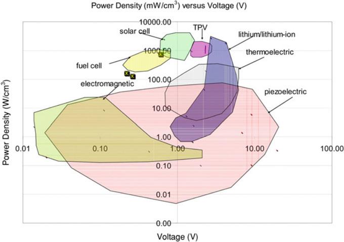
Fig. 1.2 Plot of power density versus voltage for different power supply strategies, from [27]
mechanism is due to the relative motions of two conductors separated via dielectric material. Piezoelectric effect is due to the spontaneous separation of charge within certain crystal structures under the right conditions producing an electric dipole [20], the result is that they can physically deform in the presence of an electric field, or conversely, produce an electrical potential difference due to charge separation when mechanically deformed. These mechanisms are accompanied by magnetostriction [21–23] and the use of electroactive polymers [24, 25]. As extensively explained by Erturk and Inman [26] and as can be seen even today by analysing the literature, piezoelectric transduction has received more attention over the past twenty five years. The reason can be easily understood by considering in Fig. 1.2 the famous plot drawn up by Cook-Chennault et al. in 2008 [27], which represents the power density, i.e. the electrical power generated per unit volume of the device versus the operating voltage. As can be seen, piezoelectrics intersect with the operating domain of lithium/lithium ion devices. Furthermore, they give good power output for a large range of electrical voltages. Even if dated (2008) the graph retains its importance and significance.
Piezoelectric generators have good inherent transduction capacity and they preserve the efficiency even at small scale [28]. In contrast to piezo solutions, electromagnetic is more complex to realize (e.g. coil assembly in limited space) with wafer scale system and they work at low voltages (less than 1 V [29]). The electrostatic solutions are not complex to realize even at MEMS scale ([30–33]) but they require an initial polarizing voltage or charge as specified by Beeby et al. [29]. Anyway this
1.3PiezoelectricVibrationEnergyHarvesting(PVEH)5
is not an issue in applications in which a generator charges the battery, as this can be also used to provide the necessary initial excitation level. Electrostatic generators can utilize electrets to provide the initial charge and these are capable of storing charge for many years. The output impedance of the devices is often very high, making them less suitable as power supplies. Also the output voltage is relatively high (> 100 V) and often results in a limited current supply leading to intrusive electronic circuit to manage the issue. Although particularly promising, it is also worth noting the disadvantages of piezoelectric crystals. They suffer from age, are particularly brittle [34, 35] and prone to degrating [36], and to charge leakage [37, 38].
1.3 Piezoelectric Vibration Energy Harvesting (PVEH)
The typical PVEH is a layered cantilever beam or plate. In general it is equipped with one or two layers of active (i.e. piezoelectric) material fixed on a structural layer made of semiconductor material such as silicon or metal. In case of one piezoelectric layer the harvester is named unimorph and bimorph in the case of two piezoelectric layers. In that case the layers can be electrically connected in series or parallel. Figure 1.3 shows the described structure. The basic working principle follows: the clamp of the structure is excited with an external signal of acceleration (i.e. environmental vibration), and due to this input the structure vibrates. However, the cantilever scheme is not the only one widely used, especially in the applicative field. Anton et al. installed piezoelectric patches on the wings of an unmanned aerial veichle [39–41] and also in the biomedical field to monitor in vivo the knee prostheses [42, 43]. Because of the multiphysics nature of the problem that will be deeply described in Chap. 2, the strain deformation energy caused by the vibration can be converted into electrical energy by means of piezoelectric material. To do that an electric circuit is connected to the structure (resistive in Fig. 1.3). The described system is capable to scavenge a good amount of energy (i.e. suitable for low-power electronics) only in case of high dynamic amplification. In case of harmonic forcing function (widely used in testing if one looks at the literature), it means near the resonance condition (i.e. frequency of the input very close to the frequency of the harvester). An added tip mass can be used to match a specific resonant frequency, as

Fig. 1.3 Schematic of typical piezoelectric cantilever energy harvester. Left: monomorph, right: bimorph with the addition of a tip mass to match a specific external frequency
indicated in Fig. 1.3, or by using electronic strategies [44]. Unfortunately, the enviroment that surround us, in which the EHs operate, is characterized by a energy content that is mainly distributed over frequencies within 100 Hz ([45, 46]). If one thinks to power wearable electronics, the human motion frequency contents is bewteen 1 and 5 Hz ([47, 48]). As explained in the previous section, the EHs must be small as much as possible and minimally invasive, and for this reason are characterized by high natural frequencies (hundreds or thousands of hertz). Due to the frequency mismatch the harvester remains practically in static regime. To overcome that limitation, researchers are moving on strategies that can widen the operational bandwidth of the energy harvesters (i.e. good amplification at out of resonance condition). This can be done with linear techniques or by means of nonlinear phenomena as seen starting from the first decade of 2000s ([49, 50]). There are many ways to classify energy harvesters. It is possible to proceed by transduction mechanism (piezo, electromagnetic, electrostatic), by field of application (wearable, biomedical and others), by size (MEMS or not), by operational frequency. Here, in the context of piezoelectric transduction, harvesters are presented according to the type of physics governing the problem: linear or nonlinear. The reason is mainly because the division also follows the historical path previously described.
1.3.1 Linear Systems
The group of Beeby at University of Southampton was a forerunner in transferring the work by Williams and Yates [19] to the piezoelectric field. In 2001, they presented the first resonant piezoelectric device [51]. The harvester was in that case a triangular cantilever in which the length was 23 mm and the maximum width 20 mm. The thickness was 0.1 mm for the structural layer made of AISI 316, and 20 µmfor the layer of Heraeus IP222L dielectric material screen printed onto both sides. The subsequent thick-film piezoelectric layers were deposited on both sides using multiple printings and firings. The protoype generated 2 µW of power at the resonance frequency of 80 Hz over a resistor of 333 kΩ. In that case, optimal operating conditions were not sought but only evidence of the phenomenon. Roundy in 2004 at UC Berkeley performed studies on cantilevers with also consideration of the tuning of the system at a certain frequency by means of tip tungsten alloy proof masses on the tip of the cantilever [30]. This approach has been then largely adopted to manipulate the resonance frequency. The work proposed different resonant devices with the volume constrained to 1 cm3 . The first presented device recovered 207 µW of power output with an input of acceleration amplitude of 2.25 m/s2 at the resonant frequency of 85 Hz when the harvester was connected to a load resistor of 200 k Ω. An optimized prototype was also applied to automobile tires. In his work he also provides a first simplified analytical modeling of piezoelectric harvesters. It is important to clarify at this point that such devices are classified as linear because they are thought to be governed by principles of linear dynamics. This is true under appropriate levels of excitation as will be seen in the next chapters. Other past work has been done

Fig. 1.4 Top: schematic of 33 mode and interdigitated electrodes. Bottom left : SEM of the fabricated device with bond pads. Bottom right : SEM of the cantilever from [53]
at Massachussets Institute of Technology by duToit et al. [52] and Jeon et al. [53]. In both cases the group presented a MEMS resonant energy harvester, depicted in Fig. 1.4, in which a thin film of Pb(Zr,Ti)O3 is deposited on a silicon substrate. The significant result of the first research is the individuation, by means of theoretical computation, of two distinct frequencies at which the power recovering is optimized, named respecitvely resonance or anti-resonance. This paper also presents a comparison between the so-called 33 mode (i.e., electric field and strain direction coincide) and 31 mode emphasizing the advantage of using the first one through the pioneering use of interdigitated electrodes. In the second paper, the experimental characterization of the 170 µm × 260 µm PZT beam is presented. By exciting the cantilever at its natural frequency of 13.9 kHz at the amplitude of displacement imposed by the shaker of 14 nm , the protoype generated an energy density of 0.74 mWh /cm 2 , which compares favorably to the values of lithium ion batteries.
On the theoretical side, in 2009 Renno et al. [54] focused on optimal operational condition of linear resonant PVEH. Rectangular linear devices at centimeters scale have been largely studied by Erturk and Inman [26, 55, 56] both experimentally and theoretically by means of distributed and lumped parameter models. Some researchers in the past and also in recent times focused on investigation of power densities for vaying geometries of the transducer (i.e. the piezoelectric cantilever). Baker et al. [57], in 2005 showed with experiments that by using tapered (or trapezoidal) cantilevers instead of the classical rectangular geometry it is possible to increase by 30% the power output per unit volume of the harvester. Goldschmidtboeing and Woias in 2008 also investigated tapered cantilevers both theoretically and experimentally [58]. They found that triangular-shaped beams are more effec-
tive than rectangular-shaped ones in terms of curvature homogeneity independent of the proof mass. This effect is opposed by the adverse mass distribution and the increased stiffness of triangular-shaped beams. Thus the overall efficiency is weakly influenced by shape. Triangular-shaped beams drastically outperform rectangular ones in terms of tolerable excitation amplitude and maximum output power. Other researchers, like Rosa and De Marqui Junior in 2014, focused on the effects of varying cross-sectional area with analytical models and experimental results [59]. In the area of linear devices, other subsequent efforts have been on the one hand to employ lead-free [60] (nontoxic) active materials such as aluminum nitride (AlN) and on the other hand the application of these MEMS devices not necessarily for low-frequency applications.
Marzencki et al. [61] in 2007 proposed the design and the experimental characterization of a MEMS AlN cantilever generator with a volume lower than 1 mm3 working in the frequency range of 1 kHz. The generated powers were in the range of 1 µW and the fabrication process is compatible with the complementary metal-oxidesemiconductor (CMOS) process. A typical MEMS cantilever PVEH with Zinc Oxide (ZnO) as piezoelectric material has been realized by Singh et al. [62] with a five mask SOI bulk micromachining process in 2019. Alsaad et al. [63], (2019) compared the performance of a cantilever MEMS PVEH using AlN, Lithium Niobate (LiNbO3 ) and ZnO as possible active material and aluminum, steel or silicon as substrate. They found the better combination with ZnO and Al (2.8 mW at 8.2 V). Külah et al. [64] (2022) presented a fully-implantable MEMS autonomous device for cochlear implant that mimicks the natural hearing mechanism. Even if the described linear systems are simple from a physical point of view they are very complex to realize, and they are of growing interest to the industrial world that is launching a new challenge in terms of size, and in fact we have been starting to talk about nanogenerators [46, 65]. To enhance the power efficiency Sodano and collaborators, in 2018 realized a cantilever with functionally graded nanowires interfaces PZT to improve the energy conversion [66]. Considering the same nominal volume of device, the engineeerd solution produced 7.2 times more power than the simple film-based design. Other authors focused on designing the cantilever MEMS EH at a specific frequency simply by working on the geometry [67], the proof mass [68] considering the application field [69–71] or the effect of the position of the piezoelectric film on the cantilever [72]. Simple linear cantilever systems have been the subject of interest in the past decade to realize energy recovery systems from wind vibrations. Fluid-structure interaction (FSI) is basically used to enhance harvester oscillations. The idea is to transfer the energy initially associated with fluid motion to the vibrating mode of a transductive structure (not necessarily piezoelectric) through their interaction. Various possibilities of FSI have been investigated over the years ([26, 73–78]).
1.3.1.1Broadband in Linear Systems
Slightly damped devices have great efficiency because of the large oscillations at the resonance but they confine the response to a very limited band around the structural
1.3PiezoelectricVibrationEnergyHarvesting(PVEH)9
eigenfrequency. Widening the operational band by reducing the quality factor is not a good strategy because the peak response of voltage decreases, [26, 79, 80]. An innovative concept in linear systems has been to widen the operational bandwidth of the harvesting system by means of cantilever arrays resonanting at different frequencies. In this way, the device can respond to an external vibration signal distributed at certain frequencies by activating resonators corresponding to those frequencies. Ferrari et al. [81] in 2008 proposed an array of three bimorphs, that they called multifrequency converter array (MFCA) with different natural frequencies (113 Hz, 183 Hz, 281 Hz). The harvester was connected to a single storage capacitor and an autonomous sensor system was realized. The same group presented the MFCA implementation at the MEMS scale in 2011 [79] with interdigitated electrodes to exploit the 33 mode. Xue et al. in 2011 [82] computationally investigated a system composed of ten bimorphs without tip masses and with different aspect ratio (i.e. dimensions) to match different resonant frequencies. They found a good bandwidth widening by connecting the devices in series and the fact that the operating frequency band can be shifted to the dominant frequency of the ambient vibrations by increasing or decresing the number of bimorphs connected in parallel. A design composed of a circular array of cantilever called pizza-shaped energy harvester has been also recently presented by Caetano and Savi (2022) [83]. Investigations of the detuning (i.e. difference of resonance frequency between contiguous cantilevers in an array) on the bandwith has been carried out by Dechant et al. [84] (2018), and their protoype is represented in Fig. 1.5. Other authors, like Toyabur et al. (2017) used array of cantilever with same features just to realize a multimodal system for covering wide frequency bands [85]. Similarly, Upadrashta and Yang in 2018 [86] used the concept of array of different cantilevers without piezoelectric material to activate different modes of a main vibrating piezoelectric cantilever.

Fig. 1.5 Top view and experimental apparatus of the prototype proposed by Dechant et al. in [84]
1.3.2 Nonlinear Systems
Nonlinear dynamics in mechanical systems began concretely with Huygens’ studies on pendulum [87] and in celestial mechanics. Since then, many studies have been made both in terms of mathematical modelling, computational techniques, and interpretation of phenomena. In accordance with Lacarbonara and Rega [88, 89] with the work (and the legacy) of Professor Ali H. Nayfeh, “a new paradigm in higher education and engineering called nonlinear dynamics for design has begun in our time, which involves advantageously exploiting nonlinear phenomena and principles to improve the performance of engineering systems.”
In this context, together with multiphysics phenomena, in the last 15 years or so, considerable progress has been made in the field of vibration-based energy harvesting. Various nonlinear phenomena or sources of nonlinearities (geometrical, physical) in mechanical systems have been exploited to improve the performance [90]. In the following the main works together with the phenomena are briefly discussed. Focus will be on the magnetic interaction, which is the main topic of this work.
It should be emphasized that regardless of their nature, it is possible to classify nonlinearities as either intentional, if introduced in accordance with the principle enunciated above, or inherent if due to internal sources of the mechanical system itself in its operational regime. Of course, as will be seen below, these can coexist.
1.3.2.1Snap-Through Buckling (STB) Mechanisms
One possibility for solving the frequency match problem is to use multi-stable systems with snap-through buckling (STB) of mechanical structures. This kind of systems are widely studied for even more generic purposes [91–95]. The working process is the following: the designed structure, that is typically an arc shaped beam, has more than one stable configuration, and it exploits impulsive excitation to migrate from one stable configuration to another. The advantage of the solution is that in order to activate the mechanism, it is generally not necessary for the external perturbation to have the same frequency of the mechanism. The only necessary thing is a certain energy threshold, usually provided by means of an external acceleration that can create the configuration migration in terms of the total potential energy (TPE). Such impulsive migration can be exploited, for instance, to generate an impulse at the clamp of a cantilever as done by Jung et al. [96] (2010) and by Speciale et al. [97] (2020, see Fig. 1.6), or some piezo patches can be equipped directly on the bistable mechanism, as done in the early work Baker et al. [57] (2005), or by Cottone et al. [98]. Gammaitoni and coworkers proposed also a version with electromagnetic transduction [99] (2014). Such kind of bistable systems have been studied also by Masana and Daqaq [100] in which they introduced an axial load to manipulate the potential function of the system realizing a mono-stable and a bistable depending by the presence of such force. In 2019, the bistable piezoelectric beam has been implemented at the MEMS scale by Xu et al. [101]. Andò et al. used a STB mechanical
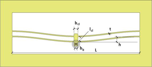
Fig. 1.6 Schematic of a bistable mechanism by Speciale et al. from [97]
system with a central proof mass installed to induce impacts on piezoelectric beams every time that STB changes configuration [102]. Arrieta et al. applied the concept of STB mechanism to piezoelectric plates [103] (2010).
1.3.2.2Impact-Based Solution
Another strategy to enhance the behaviour of piezoelectric harvester is the so called frequency up-conversion (FuC) mechanism. The concept of frequency conversion of a signal is widespread especially in electronics and telecommunications [104]. It is a process by which a system translates the frequency energy spectrum of a signal while keeping unchanged the distances between different components and in electronics systems also the bandwith of the original signal. The frequency converter (or changer ) (FC) is classified as up-converter if the output frequencies are higher than the ones of the input. In the opposite case it is called down-converter. In telecommunications, this procedure can be carried out by means of a mixer that is a nonlinear circuit. They are commonly used to convert the frequency of AC power or to control the velocity of AC motors for pumps and fans. In the last decade, this concept has been carried into the vibration energy harvesting context with the aim of having good dynamic amplification of the high-frequency harvester even though the input signal is at low-frequency. One possibility of FuC can be made with impacts by exploting a moving low-frequency mass to forcing impulsively the harvester. Throughout history, essentially two solutions have been explored: the first one concerns the impact directly on the harvester, the second one the indirect impact on elastic supports interacting with the harvester, giving rise to piecewise linear systems [90] (such as the package or stoppers). Early investigations on this concept have been carried out by Umeda et al. [105] (1996) on a boundary-clamped piezoelectric plate stimulated by the free fall impact of a steel ball. The principle is depicted in Fig. 1.7 (left). In that case a nonlinearity arises due to the fact that the system can vibrate at two frequencies: one just after the impact in which plate and ball travel attached and one after the split. However, after the impact the vibrational phenomenon of the plate is that of

Fig. 1.7 Left : schematic from early investigations on PVEH from impacts by Umeda et al. [105]. Right : schematic of the prototype by Ju and Ji [107]
a linear oscillator with assigned initial conditions of velocity and displacement. The latter approach has been exploited recently by Nastro et al. [106] (2022) to realize a wearable energy harvester by means of a wristband and watchband. To safeguard the piezoelectric material, the impacts can be provided to it indirectly. Ju and Ji [107] (2018) realized a piezoelectric harvester in which the vibration of the transducer is activated through the impacts of a metal sphere free to move in a closed compartment on the device walls (see right side of Fig. 1.7). Recently, Rosso et al. [108] proposed a mixed enhancement of a cantilever piezoelectric energy harvester through indirect impacts on the package of a mono-axial moving mass and nonlinear magnetic interaction between that mass and the cantilever. They experimentally proved that magnetic interaction is not always beneficial, depending on the energy levels of the motion. There are also techniques using indirect impact and mixed transduction mechanism Halim et al. [109] (2019). They realized a doubly-clamped piezoelectric beam with a central magnetic mass on the bottom of the transducer and a central iron mass on the top. The mass above is impacted by another moving mass in a guide and it activates the vibration of the piezoelectric. At the same time, a coil placed below the magnetic mass collects energy from changes in the magnetic field due to the relative motion.
1.3.2.3Mechanical
Plucking-Based Frequency Up-Conversion
The idea of this approach is to impose an initial quasi-static displacement via flexible plectrum to the tip of the piezoelectric transducer and a sudden release of that condition. The dynamic consequence is a free vibration regime of the piezoelectric beam at its natural frequency that allows to recover electrical energy from voltage oscillations. One of the first concepts has been proposed by Pozzi et al. in 2011 [110] with the so called pizzicato harvester. They proposed a knee-joint wearable device [111](seeFig. 1.8) that exploits the relative rotation between the shank and the thigh to pluck piezoelectric bimorphs clamped on a hub via plectra distributed over an outer ring. At Georgia Tech, Kathpalia et al. [112] developed a theoretical model and also the experimental validation of a similar kind of system in which a nonlinear flexible plectrum plucks the piezoelectric beam along a straight path. They

Fig. 1.8 Top, from left to right : schematic of pizzicato harvester and prototype by Pozzi et al. from [111]. Bottom, from left to right : schematic mechanism of the plucking and experimental setup proposed by Kathpalia et al. from [112]
identified also a dependence of the performance of the harvester on the geometry of the plectrum. Their experimental setup is depicted in Fig. 1.8 (bottom).
The mechanical plucking has been also successfully implemented at the MEMS scale by Janphuang et al. [113]. The design consists of a rotating gear plucking a MEMS cantilever with its teeth that could be driven by an oscillating mass. The main drawback of these kind of system is the fact that piezoelectric crystals are very brittle and the mechanical contact could damage the transducers. Taking into account this, Pozzi proposed also a contactless version of pizzicato [114].
1.3.2.4Magnetic Interaction Broadband and Plucking Mechanisms
The broadening of the bandwidth via magnetic interaction has the purpose of introducing intentional nonlinearities for the manipulation of the system potential. In general, a system of that type can be monostable or multistable. The interaction can be used simply to improve the response of the system in terms of the amplitude of the oscillations out of the resonance condition of the corresponding linear system (i.e. the cantilever) or to pluck the piezoelectric cantilever. In the latter case, the harvester interacts with other systems like oscillators and rotors. In 2009, Erturk et al. presented the integration of the chaotic strange attractor by Moon and Holmes [115] with piezoelectric layers [49] creating the so called piezomagnetoelastic energy

Fig. 1.9 Top, from left to right : schematic of the strange attractor studied by Moon and Holmes, same concept with piezoelectric layers proposed by Erturk et al. from [49], and example of the comparison between linear and nonlinear response for harmonic excitation, from [118]. Bottom, from left to right : schematic and prototype of the reversible hysteretic energy harvester by Stanton, from [119]
harvester. Through theoretical investigations and experiments conducted on a ferromagnetic beam 145 mm long, 26 mm wide and 0.26 mm thick, the nonlinear harvesters showed an increasing of the open circuit (OC) voltage of 200% with respect to the linear case. Through the presence of the ferromagnetic cantilever and the magnets indicated in (Fig. 1.9), the system is multistable, and the number of equilibrium points depends on the magnets spacing. Erturk exploited a layout with three (two stable) equilibrium points giving rise to the Duffing oscillator [116, 117]. This kind of system allowed to reach larger amplitude in comparison with the linear system due the shape of the magnetoelastic potential. The comparison of the dynamic response has been largely investigated in a later work of the same group [118]. Also Cottone et al. [50] in 2009 proposed a similar device with same consideration on the potential energy of the system depending on the magnets spacing.
In the same year Stanton et al. [119, 120] at Duke University proposed a method to invoke softening or hardening response by a suitable tuning of the relative distance between a tip magnet put on the harvester and a couple of magnets mounted on an elastic support. In that way the bandwith is increased with hysteretical behavior and it is reached a good performance out of resonance condition. It could be said that with the aforemetioned works, a new prolific era started in piezoelectric vibration energy harvesting via magnetic interaction. Ferrari et al. [121, 122] (2010) studied a ferromagnetic cantilever with piezoelectric film similarly to Erturk but only with a single magnet at the ground. Since then, these kinds of systems have always been the subject of great interest both for theoretical investigations and modeling [123–127], also with higher number of stable configurations [128]. Recently Tao-Hai
et al. [129] (2022) studied a bistable evaluating the performance under both galloping from wind and base excitation. Another interesting possibilty to exploit the bistability has been explored by Kim et al. [130]. They mounted on the same elastic support two neighboring cantilevers with longitudinal axes orthogonal to each other and equipped with a tip magnet. When the system is subjected to an external vibration, the interaction between the magnets amplifies the dynamics of both oscillators leading to band broadening with better performance than a standard bistable system (i.e., without magnetic coupling between two cantilevers). A similar concept has been developed by other authors, such as Yang et al. [131] with focus on the internal resonance. In 2020, Chandwani et al. [132] used a scheme of the magnetic interaction like Ferrari [121] to merge two distinct wide frequency operational bands due to another sources of nolinearity caused by a tip mass with a position-varying center of gravity (COG) through rolling cylinders. The literature shows that multistable solutions has been successfully implemented at the MEMS scale. Wu et al. [133] proposed a MEMS energy harvester with magnetically coupled oscillators. They obtained 41.6 µW ) of power with an impedance of 0.3 MΩ. The object exibithed good values of voltages (order of Volts) below 50 Hz. Other works with coupled systems with a central spring-magnetic mass interacting with piezoelectric beams can be found in [134, 135].
The magnetic interaction is also used in mixed energy conversion mechanisms. In that framework, Li et al. [136], designed an energy harvester that can scavenge energy via piezoelectric and electromagnetic transduction. The magnetic force is used to amplify the vibration of a drive-beam equipped with a magnet. The spatial variation of the magnetic flux due to the oscillation is then used to scavenge energy with a coil around the tip magnet. Furthermore, the driving beam bumps a piezoelectric transducer realizing an impact-based FuC.
The principle of frequency up-conversion using magnets is slightly different with respect to the previous illustrated broadband magnetic mechanisms as explained by Tang et al. [137]. In this latter case, piezoelectric cantilever and magnets are applied with base excitations as a whole. Instead, in the frequency up-conversion mechanism, the piezoelectric cantilever typically stands still and is excited by magnetic force applied at the free end. In general, one magnet is put as in the previous cases on the tip of the cantilever, the other one is constrained to a seismic mass, that is a mechanical system moving at low-frequencies. In general, in literature, it can be found two possibilities for the motion of the seismic mass. In the first case it is a mechanical system able to vibrate at very low-frequencies in comparison to the piezoelectric transducer [138]. In the other case it is a wheel or a rotational mechanism activated from an external source (this case is very common in literature). The magnetic FuC has been largely investigated in literature starting from 2011. Tang et al. [139] (different researcher from the previous one), proposed a system composed of two opposite piezoelectric cantilevers with a magnetic tip mass and a central compartment hosting a moving magnet for external input acceleration. The prototype, realized at the centimeter scale, resulted in average power generation of over 10 µW within a broad frequency range of 10–22 Hz under 1g acceleration. Pillastch et al. realized a prototype, depicted in Fig. 1.10, working through magnetic plucking based on a proof
mass rotating mechanism [140, 141]. They also carried out modelling (2014) about FuC [142], using for the piezoelectric beams the electromechanical model proposed in [26] and for the magnetic interaction both an inverse square approach and finite element simulation. They concluded that the inverse square, even if cannot match the accuracy of a complete finite element simulation, can give some information on the system behavior. In 2012, the same group proposed an experimental work on the basis of the same principle in which a rolling external proof mass actuates an array of piezoelectric cantilevers that form a distribuited transduction mechanism [143]. At an excitation frequency of 2 Hz and an acceleration of 2.72 m/s2 a power output of 2.1 mW was achieved. analyzing the literature, it is immediate to realize that since then, much attention has been paid to the rotational mechanisms to implement the harvester.
Ramezanpour et al. [144, 145] (2016) used a rotating pendulum with a gear. Those works demonstrate an increasing output voltage if the number of magnets on the gear increases. Xue and Roundy [146] in 2017 used a concept similar to that one by Pillatsch with a rotating proof mass externally driven to find the best configurations between the poles of the magnets to improve the performance of the PVEH [147]. They found a dynamics highly dominated by the first mode of vibration for the so called in-plane plucking in which the poles of the magnets are parallel to the beam axis. They also pointed out power in the order of the mW below 8 Hz of frequency of the rotor. In that case the magnetic force is modelled through the multi-dipole approach that will be object of studies in the following. Shu et al. in 2018 studied a similar system with a standard interface circuit that includes an AC-DC rectifier followed by a large filtering capacitance [148]. They used a dipole-dipole approach to model the magnetic interaction with comparison with some experimental results. Dauksevicius et al. in the same year carried out an in-depth study on some physical aspects of plucking dynamics [149]. They propose a computational study via finite element on the dependence of the magnetic force by the gap between the magnets. After that, they propose to experimentally study the influence on the cantilever response of the plucking speed, the gap between the magnets which they call clearance, and the value of the load resistor. They identify, as their convention, three typical phases of operation of the transducer: a quasi-static phenomenon,a transition regime and another one fully dominated by the dynamics of the first mode. Although it is a rare study that focuses on the speed of interaction, it does not propose any validation of the magnetic phenomenon apart, moreover there is no consideration of the possibility of changing in the behavior of the material, such as the possible arising of material nonlinearities effects for variations of magnetic force. Furthermore, also in this case the dynamics is studied on a rotating system, and being the magnetic force positional in its nature, the result is not generalizable. After that, Kleiva and Dauksevicius investigated the multimagnet excitation and realized also a protoype with a rectilinear driving magnet constraint for wearable application [150, 151]. Other similar mechanisms have been largely investigated [152–154] (see Fig. 1.10) also with combination with snap-through mechanism [155]. An innovative contribution has been provided in 2021 by Lo et al. [156]. It is proposed a magnetic plucking via rotor mechanism in two distinct points (at the tip and in the middle)

Fig. 1.10 Top, from left to right : schematic of the energy harvester using magnetic frequency upconversion and example of beam tip displacement under the magnetic plucking, by Fu and Yeatman [152]. Bottom, from left to right : prototype of energy harvester based on rotating proof mass designed by Pillatsch et al. from [140]. Schematic of the mixed modes energy harvester proposed by Lo [156]
of a piezoelectric cantilever at the same time. In this way it is possible to activate two vibrational modes and have both a frequency up-conversion and a broadband. The schematic of the latter mechanism is depicted in Fig. 1.10 (bottom right). The magnetic plucking principle has been also exploited in electromagnetic [157] and mixed piezo-magnetic transduction [158]. Recently, Bodduluri et al. [159] proposed the magnetic plucking at the MEMS scale with an integrated process of the magnetic material deposition.
1.3.2.5Other Kind of Nonlinearities and Electronics Circuits
Many other forms of mechanical intentional nonlinearities can be found in the literature to improve harvester performance. Typically, these are nonlinearities exhibited through design features; we do not refer here to inherent material nonlinearities that will be investigated in depth later. Some works are completely general and simply emphasize the nonlinear effect in device modeling. In 2014 Cammarano et al. [160] proposed an analytical and experimental study on a nonlinear oscillator with the introduction of cubic stiffness. They studied the effects of different parameters (input acceleration, damping, nonlinear stiffness) on the bandwidth. Their result fits every case in which the system can be described with that kind of nonlinearity and it
provides optimal operational conditions. Zou et al. [161] (2021) find a way to introduce a nonlinear interaction force via a pre-compressed spring, a miniature bearing, and a raceway that induces a load at the end of a cantilever piezoelectric beam. In this way, it is possible to realize a mono/bi/tri-stable energy harvester depending on the layout of the spring and so, to manipulate the desirable nonlinearity of the mechanical system. Other designs make use of pendulum systems [162] combined also with magnetic interaction for a broadband system [163, 164]. This work is focused on the mechanical part of PVEH. The electrical part will be simply schematized as a resistor as made by other researchers [26, 54]. However, in general various electronic circuits can be employed to manage the electrical energy recovered by the harvester. Ottman et al. realized an adaptive control technique for the dc-dc converter of the harvester to match continuously the optimal load [165]. After that, they presented an optimimized method to harvest energy from a piezoelectric beam using a step-down dc-dc converter [166]. Other studies performed by the group of Guyomar proposed the so called syncronized switch harvesting on inductor (SSHI) nonlinear technique which is efficient in non-resonant systems [167–169]. Silva et al. [170], in 2019, used nonlinear switching circuits on the M-shaped energy harvester designed by Leadenam [171]. Leadenham and Erturk [172] investigated the nonlinear process of AC-DC conversion with non-ideal diodes. A recent nonlinear mechanism has been proposed by Bonnin et al. [173]. They designed an impedance matching network that can amplify the dynamics response of the harvester at a frequency chosen by the designer. Yan et al. [174], and Yu and Zhou [175] used the combination inductorresistor to widen the frequency band. These references show that also nonlinear electronics is subjected to intensive investigations.
References
1. Gad-el-Hak M (2005) MEMS design and fabrication. Taylor & Francis Group
2. Senturia SD (2001) Microsystem design. Springer, New York, NY
3. Maluf N, Williams K (2004) An introduction to microelectromechanical systems engineering. Artech House, Inc
4. Feynman RP (1959) There’s plenty of room at the bottom: an invitation to enter a new field of physics. Lecture to American Physical Society, California Institute of Technology. https:// calteches.library.caltech.edu/ 1976/
5. Nathanson HC, Newell WE, Wickstorm RA, Davis JR (1967) The resonant gate transistor. IEEE Trans Electron Devices ED-14(3):117–133
6. Corigliano A, Ardito R, Comi C, Frangi F, Ghisi A, Mariani S (2017) Mechanics of microsystems. Wiley
7. Adams TM, Layton RA (2010) Introductory MEMS, fabrication and application. Springer
8. Younis MI (2010) MEMS linear and nonlinear statics and dynamics. Springer
9. Sandia National Laboratories website. https:// www.sandia.gov/ mesa/ mems- video- imagegallery/
10. xMEMS website. https:// xmems.com/
11. Boussey J (2002) Microsystems technology: fabrication test and reliability. Hermes Science Publications
12. Développement Y (2021) Status of the MEMS industry
13. Tummala RR (2004) Fundamentals of microsystems packaging. McGraw-Hill
14. Lobontiu N, Garcia E (2005) Mechanics of microelectromechanical systems. Springer
15. Roylance ML, Angell JB (1979) A batch-fabricated silicon accelerometer. IEEE Trans Electron Devices ED-26(12):1911–1917
16. Leondes CT (2005) MEMS/NEMS handbook techniques and applications. Springer
17. Pepite ST (2022) Viaggio nella "clean room" di Agrate 300-STMicroelectronics. YouTube website. https:// www.youtube.com/ watch?v=hqzcWOFLVDE
18. Briand D, Yeatman E, Roundy S (2015) Micro energy harvesting. Wiley-CH
19. Williams CB, Yates RB (1996) Analysis of a micro-electric generator for microsystems. Sens Actuators A 52(52):8–11
20. Roundy S, Wright PK, Rabaey JM (2004) Energy scavenging for wireless sensor networks with special focus on vibrations. Springer
21. Wang L, Yuan FG (2008) Vibration energy harvesting by magnetostrictive material. Smart Mater Struct 17:045009 (14pp)
22. Saha O, Andersen E, Roundy S (2021) Wireless power transfer by self-biased magnetoelectric laminate for biomedical implants. In: 2021 IEEE 20th international conference on micro and nanotechnology for power generation and energy conversion applications (PowerMEMS), Exeter, UK
23. Borkar H, Gaikwad VM, Dutta S, Tomar M, Gupta V, Kumar A (2022) Lead-free laminated structures for eco-friendly energy harvesters and magnetoelectric sensors. J Phys Chem Solids 160
24. Lallart M, Cottinet PJ, Guyomar D, Lebrun L (2012) Electrostrictive polymers for mechanical energy harvesting. J Polym Sci Part B Polym Phys 50:523–535
25. Liu Y, Ren KL, Hofman HF, Zhang Q (2005) Investigation of electrostrictive polymers for energy harvesting. IEEE Trans Ultrason Ferroelectr Freq Control 52(12):2411–2417
26. Erturk A, Inman DJ (2011) Piezoelectric energy harvesting. Wiley
27. Cook-Chennault KA, Thambi N, Sastry AN (2008) Powering MEMS portable devices-a review of non-regenerative and regenerative power supply systems with special emphasis on piezoelectric energy harvesting systems. Smart Mater Struct 17:043001
28. Safaei M, Sodano HA, Anton SR (2019) A review of energy harvesting using piezoelectric materials: state-of-the-art a decade later (2008–2018). Smart Mater Struct 28:113001 (62pp)
29. Beeby SP, Tudor MJ, White NM (2006) Energy harvesting vibration sources for microsystems applications. Meas Sci Technol 17:R175–R195
30. Roundy S (2003) Energy scavenging for wireless sensor nodes with a focus on vibration to electricity conversion. PhD thesis, University of California, Berkeley
31. Roundy S, Wright P, Pister K (2002) Micro-electrostatic vibration-to-electricity converters. In: Proceedings of IMECE 2002, pp 1–10
32. Miao P, Mitcheson PD, Holmes AS, Yeatman EM, Green TC, Stark BH (2006) Mems inertial power generators for biomedical applications. Microsyst Technol 12:1079–1083
33. Basset P, Galayko D, Cottone F, Guillemet R, Blokhina E, Marty F, Bourouina T (2014) Electrostatic vibration energy harvester with combined effect of electrical nonlinearities and mechanical impact. J Micromechanics Microengineering 24:035001 (14pp)
34. Anton SR, Sodano HA (2007) A review of power harvesting using piezoelectric materials (2003–2006). Smart Mater Struct 16
35. Anton SR, Erturk A, Inman DJ (2012a) Bending strength of piezoelectric ceramics and single crystals for multifunctional load-bearing applications. IEEE Trans Ultrason Ferroelectr Freq Control 59(6)
36. Pillatsch P, Xiao BL, Shashoua N, Gramling HM, Yeatman EM, Wright PK (2017) Degradation of bimorph piezoelectric bending beams in energy harvesting applications. Smart Mater Struct 26(3):035046
37. Stojˇcev MK, Kosanovi´c MR, Golubovi´c LR (2009) Power management and energy harvesting techniques for wireless sensor nodes. In: TELKSIS 2009, pp 65–72
38. Chalasani S, Conrad J (2008) A survey of energy harvesting sources for embedded systems. In: Proceedings of IEEE SoutheastCon, pp 442–447. http:// www.citeulike.org/ user/ macgyveremir/ article/ 3041664
Another random document with no related content on Scribd:
»Kerron sinulle myöhemmin, kun meillä on enemmän aikaa jutella.»
»Odotahan», jatkoi Helen. »Sinähän puhuit usein — kas sehän on totta, juuri tuosta nuoresta miehestä, jonka kanssa äsken juttelit, kun huusin sinua — Phil Actonista.» Hän katsahti puhuessaan tielle, mutta Phil oli sillä välin hävinnyt.
»Älä puhu hänestä, Helen kulta — se oli vain minun koulutyttöhulluttelujani. Kun palasin kotiin, niin huomasin, kuinka mahdotonta kaikki oli. Mutta nyt minun täytyy mennä toisten luo. Etkö tule tervehtimään heitä?»
Mutta ennen kuin Helen ehti vastata, huusi joku: »Nyt ne lähtevät!» ja jokainen katsoi torille, missä kilpailevat autot toitottivat sinisen bensiinipilven keskellä.
Helen nosti kiikarinsa: »Nyt emme voi mennä, Kitty. Sinun täytyy odottaa siksi, kunnes autot ovat lähteneet. Sitten tulen kanssasi.»
Helenin laskettua kiikarinsa ojensi hänen vieressään seisova Stan kätensä: »Annahan minunkin kurkistaa, Helen. Vanha ystäväni, tuomari Morris Prescottista kuuluu olevan palkintotuomarina.» Hän nosti kiikarin silmilleen. »Tuolla hän on; katsohan häntä, Helen hän on maailman paras mies!» Hän antoi kiikarin vaimolleen. »Jos tahdot nähdä oikean lännen lakimiehen, niin katso tuota kookasta miestä, jolla on harmaa puku.»
Samassa kuului takaa syvä, miehekäs ääni: »Terve, Manning! Kai teillä on hetkinen aikaa jutella vanhojen ystävienne kanssa?»
Stanford käännähti ja tarttui iloisesti yllätettynä Rovastin ojennettuun käteen. Pitäen yhä kiinni siitä hän kääntyi vaimonsa puoleen, joka katsoi heihin hymyillen: »Helen, tässä on herra Baldwin — Rovasti, tiedäthän.»
»Totta kai tunnen Rovastin», huudahti Helen ojentaen vuorostaan kätensä. »Stanford on kertonut minulle niin paljon teistä, että olen jo etukäteen rakastunut teihin.»
»Ja minä», vastasi Rovasti sinisten silmien loistaessa mielihyvästä, »minä luulen olleeni aina rakastunut teihin. Minua ilahduttaa, että Manning on osoittanut omaavansa niin hyvän maun. Onko siellä idässä enemmänkin teidän kaltaisianne tyttöjä? Jos niin on, niin minun täytyy tehdä matka sinne, ennen kuin tulen liian vanhaksi.»
»Will-setä!» huusi Kitty. »Häpeän sinun puolestasi! En olisi luullut sinun häpäisevän kotilaakson väkeä tällä tavoin!»
Rovasti nosti lakkiaan ja harasi harmahtavaa tukkaansa kuin olisi joutunut kiinni pahasta teosta. Sitten hän vastasi: »No mutta Kitty, tiedäthän, etten voisi rakastaa ainoatakaan toisia tyttöä niin kuin sinua. Sinähän kuulut minulle yhtä paljon kuin omalle isällesi ja äidillesi. Mutta katsohan, kultaseni, meidän täytyy olla kohteliaita vieraillemme, senhän voit ymmärtää.»
Kun kaikki olivat tarpeekseen nauraneet Rovastin selitykselle, kertoi Kitty, että rouva Manning oli hänen hyvä ystävänsä ja koulutoverinsa Helen Wakefield ja että hän tulisi Kittyn luo viemisille vietettyään kuherruskuukautensa Graniittiylängöllä.
»Aiotte viettää ulkoilmaelämää Graniittiylängöllä, niinkö?» sanoi
Rovasti Stanfordille. »Siellä tapaatte varmasti jonkun minun pojistani. He lähtevät sinne ensi viikolla kokoamaan karanneita härkiämme.»
»Sehän olisi hauskaa», vastasi Stanford. »Helen on juuri valittanut, ettei täällä näe ainoatakaan paimenta. Osoitin hänelle Phil Actonin, mutta hän ei näytä tyydyttävän Helenin vaatimuksia. Hän ei ota uskoakseen, että hän on paimen.»
Rovasti nauroi. »Hänhän on ollut paimen koko ikänsä. Parempaa ette löydä mistään. Mutta hän ei tänä vuonna ota osaa ratsastuskilpailuun.»
»Miksi ei?»
»En tiedä. Hän on saanut jonkin hullun päähänpiston, ettei aio ruveta markkinailveilijäksi, niin hän sanoi. Mutta minulla on tänä vuonna kartanossani toinen mies», hän lisäsi ikäänkuin haluten vaihtaa puheenaihetta, »joka ratsastaa miltei yhtä hyvin kuin Phil viime vuonna. Hänen nimensä on Patches. Hän on kelpo poika.»
Kitty, joka oli katsellut tielle Rovastin puhuessa, laski kätensä Helenin käsivarrelle. »Katsohan tuonne, Helen. Tuolla Patches on tuo mies, joka istuu hevosen selässä tien risteyksessä, aivan vuoren juurella nuorien ulkopuolella.»
Helen suuntasi kiikarinsa Kittyn neuvon mukaan. »Näen hänet», hän huudahti. »No niin, hän on enemmän sen näköinen kuin kuvittelen oikean paimenen olevan. Onpa hän tosiaan komea!» Hänen lähemmin tarkastellessaan ratsastajaa levisi hämmästynyt ilme hänen kasvoilleen. »Mutta Kitty!» hän sanoi matalalla äänellä,
niin että heidän vieressään seisovat miehet eivät voineet kuulla hänen sanojaan. »Tiedätkö ketä tuo mies muistuttaa?» Hän epäröi ja laski alas kiikarin katsoakseen ystäväänsä puoliksi huvittunut, puoliksi hämmentynyt ilme kasvoillaan, »hän muistuttaa Lawrence Knightiä».
Kittyn ruskeat, iloiset silmät välkkyivät veitikkamaisuutta. »Mutta rouva Manning, häpeän sinun puolestasi! Ennen kuin kuherruskuukautesi on tuskin alkanut, niin sinun ajatuksesi jo niinkin vähäpätöisestä aiheesta kuin härkäpaimenen ilmaantumisesta johtuvat entiseen miljoonamiesihailijaasi. Minä —»
»Kitty! Ole vaiti!» varoitti Helen.
Hän kohotti jälleen kiikarinsa katsoakseen paimenta uudelleen.
»Sinulla taitaa olla omantunnonvaivoja, vai mitä?» naljaili Kitty hiljaa. »Mutta sanohan, lapsikulta, kuinka oikeastaan menetit hänet.»
»En minä menettänyt häntä», vastasi Helen yhä katsellen Patchesia, »vaan hän menetti minut.»
Kitty oli olevinaan suunniltaan hämmästyksestä. »Mitä? Monimiljoonikko
Knightin ei onnistunut kietoa kaunista Heleniä kultaisiin pauloihinsa? Onpa vaikea sitä uskoa!»
»Katsohan tuota miestä», kuiskasi Helen ylpeänä osoittaen miestään, »niin voit uskoa sen.»
Kitty nauroi niin hilpeästi, että Stanford kääntyi hymyillen heihin päin.
»Älkää ihmetelkö, herra Manning», selitti Kitty, »me vain uudistamme vanhoja muistojamme.»
»Älkää vain laiminlyökö kilpailua», vastasi tämä, »vaunut ovat valmiina lähtemään. Näyttää siltä kuin lähtömerkki annettaisiin tuossa tuokiossa.»
»Ja ajattelehan», jatkoi Kitty mietteitään Stanfordin jälleen käännyttyä poispäin, »etten koskaan saanut edes nähdä Knightraukan kuvaa. Mutta sinähän pidit paljon hänestä, etkö pitänytkin, Helen?» lisäsi hän Helenin jälleen kohottaessa kiikarin silmilleen. Ja nyt rouva Manning kuuli hänen äänensä olevan vakavamman kuin äsken. Tuntui kuin Kitty olisi ystävänsä kohtaloista etsinyt neuvoa ja tukea omille päätöksilleen.
»Kyllä, Kitty, pidin hyvin paljon Lawrence Knightistä», vastasi hän vilpittömästi. »Hän oli monessa suhteessa kelpo poika — minun hyvä ystäväni. Sekä Stanford että minä pidämme vieläkin hänestä; he ovat koulutovereita. Mutta Kitty kulta, eihän Larrya saattaisi ottaa vakavalta kannalla — hänhän on niin — kuinka sanoisin auttamattomasti arvoton.»
»Arvoton! Hänkö — monine miljoonineen?»
»Kitty, kyllä tiedät, mitä tarkoitan. Mutta me olemme totisesti puhuneet tarpeeksi Lawrence Knightistä. Minun pitää vielä katsoa tuota paimenta. Hän näyttää oikealta mieheltä. Minkä Rovasti sanoikaan hänen nimensä olevan?»
»Patches.»
»Niin — niinhän se oli. Hullunkurinen nimi — Patches.»
»Honourable Patches», lisäsi Kitty.
»Sepä hupaista! Tulehan tänne, Stan. Ota kiikari ja katso tuota paimenta.»
Stanford suuntasi kiikarin vaimonsa osoittamaan suuntaan.
»Eikö hän muistutakin Larry Knightiä?»
»Larry Knightiä?» Stanford katsahti vaimoonsa. »Tuo karjapaimen! Larry Knightiä? Sitä en totisesti voi sanoa. Hyvä Luoja! olisipa hienostunut ja keikarimainen Larry mielissään tietäessään olevansa sinun mielestäsi härkäpaimenen näköinen!»
»Mutta otahan kiikarisi! Nyt ne lähtevät!»
Helenin katsoessa kiikariinsa antoi tuomari Morris lähtömerkin, ja ensimmäinen kilpaileva auto lähti liikkeelle nousten kevyesti mäkistä tietä ihailevien kansanjoukkojen lomitse. Silmänräpäystä myöhemmin Helen Manning näki tapauksen, joka sai jokaisen katselijan sydämen värähtämään kauhusta.
Suuren auton kiitäessä täyttä vauhtia vuorenrinnettä ylös riistäytyi muuan pieni poika äitinsä kädestä, ja ennen kuin kukaan huomasi, oli lapsi juossut keskelle tietä, jota myöten auto huimaavaa vauhtia läheni. Huutava ja riemuitseva väkijoukko vaikeni. Helen saattoi nähdä lapsen kasvot sen kääntyessä onnellisena nauraen äitiinsä päin. Kauhun jäykistämänä hän ei saattanut laskea kiikariaan, vaan odotti kuin kivettyneenä onnettomuutta, joka ei näyttänyt olevan vältettävissä. Saattaisiko ajaja ajoissa väistää? Ja vaikkapa hän sen tekisikin, eikö lapsi kenties äkillisen pelon vallassa juoksisi suoraan vaunun eteen? Sitten Helen näki paimenen, joka oli herättänyt
hänen mielenkiintoaan, nojautuvan eteenpäin satulassa ja painavan kannuksensa syvälle hevosen kylkiin. Tuskasta säpsähtäen se hyppäsi köyden yli ja karautti vinhaa vauhtia lasta ja lähenevää autoa kohden. Ihmisjoukko katseli mykistyen miehen uhkarohkeutta. Kaikki tapahtui silmänräpäyksessä. Sivuuttaessaan lapsen Patches nojautui sivulle satulassaan siepaten sen käsivarsilleen samassa hetkessä kuin auto suhahti ohitse.
Samassa väkijoukko puhkesi äänekkääseen riemuun. Miehet huusivat ja hurrasivat, naiset nauroivat ja itkivät. Paimenen tuodessa pelästyneen lapsen takaisin sen äidin luokse ojentautui kymmeniä käsiä kiittämään ja tervehtimään häntä. Mutta kiihtynyt hevonen ei pysynyt paikoillaan, — joku kohotti nuoraa, ja Patches hävisi muiden ratsastajien joukkoon.
Helenin silmät olivat kosteat, mutta hän hymyili. »Ei», hän virkkoi hiljaa Kitylle ja Stanfordille, »se ei ollut Lawrence Knight. Larry raukka ei olisi pystynyt sellaiseen.»
Oli jo iltapäivä, kun Kitty syötyään päivällistä vanhempiensa ja veljiensä kanssa erään prescottilaisen ystävänsä luona sivuutti torin matkallaan Manningien luo, joiden kanssa oli päättänyt viettää iltansa. Pienen puiston rauhaisimmassa nurkassa, raatihuoneen takana, hän tapasi Patchesin. Paimen, joka nyt oli vaihtanut ratsastustamineensa tavalliseen pukuun, istui yksinään penkillä lukien kirjettä eikä edes huomannut Kittyn lähestymistä. Tämä pysähtyi huomatessaan Patchesin ja silmäili häntä hetkisen uuden mielenkiinnon vallassa.
Hän oli jo aivan Patchesin vieressä, ennen kuin tämä näki hänet. Mies hypähti viipymättä seisaalleen, työnsi kirjeen taskuunsa ja seisoi hänen edessään hattu kädessä valmiina tervehtimään Kittyä.
Katsoessaan mieheen Kitty tunsi selvemmin kuin ennen, että tämä mies olisi hienoimmassakin seurassa kuin kotonaan.
»Taisin häiritä teitä», sanoi Kitty. »Tieni vei tästä ohitse.»
»Ette ollenkaan», väitti Patches. »Olen iloinen, jos voitte lahjoittaa minulle hetkisen juhlapäivästänne. Tiedän teillä olevan täällä joukoittain ystäviä — ja minä olen vallan yksin. Curly ja Bob juhlivat tänään voimiensa takaa, — Rovasti ja äiti ovat päivällisellä tuttaviensa kanssa, ja Phil on piilottautunut jonnekin!»
Oli hänen kaltaistaan mainita Philin nimi miltei ensimmäisiksi sanoikseen. Ja taas Kitty, kuten viimeisten kuukausien aikana usein ennenkin, vertasi vaistomaisesti näitä kahta miestä toisiinsa.
»Minua vain halutti sanoa teille —», hän empi miten jatkaa, »herra Patches —»
»Anteeksi», keskeytti mies hymyillen.
»No niin, Patches, olkoon menneeksi, mutta te näytätte tuossa puvussa aivan toisenlaiselta. Tahdoin vain sanoa teille, että näin, mitä tänään aamupäivällä tapahtui. Se oli suurenmoista!»
»Ei, neiti Reid, te tiedätte, ettei se ollut mitään. Autonajaja olisi luultavasti joka tapauksessa väistänyt lasta. Minä toimin taas aivan harkitsematta, hetkellisestä mielenjohteesta. On niin minun tapaistani tehdä aina jotakin turhaa ja järjetöntä.»
»On paljon luultavampaa, että autonkuljettaja olisi ajanut lapsen yli, hänhän oli sitä paitsi taitamaton eikä näyttänyt ensinkään varmalta», vastasi Kitty lämpimästi. »Oli onni, että joukossa oli joku, joka toimi rupeamatta ensin ajattelemaan. Kaikki sanovat samaa.
Vanha Rovasti-kulta on niin mielissään, kuin olisitte hänen oma poikansa.»
»Liioittelette», vastasi Patches ilmeisesti hämillään tytön kiitoksesta. »Sanokaahan, huvittaako juhla teitä? Ja mikä Philiä vaivaa? Ettekö te saa häntä ottamaan osaa ratsastuskilpailuun? Emmehän voi antaa mestaruutta pois Yavapai Countysta, vai mitä?»
Miksi hänen täytyikin aina johdattaa puhe Philiin? kysyi tyttö itseltään.
»Luulen Philin tietävän ystäviensä mielipiteen hänen menettelystään», hän vastasi viileästi. »Jollei hän tahdo ottaa sitä huomioon, on se hänen asiansa.»
Patches huomasi tehneensä erehdyksen ja riensi siirtymään varmemmalle pohjalle.
»Tehän näitte autokilpailujen alun? Kai jäätte tänne katsomaan palkintojen jakoa?»
»Jään kyllä. Olen juuri matkalla tapaamaan ystäviäni, herra ja rouva Stanford Manningia. Aiomme yhdessä mennä katsomaan kilpailujen jatkumista.»
Hän katsoi kiinteästi Patchesiin, mutta pieninkään ilme tämän kasvoissa ei osoittanut, että hän olisi ennen kuullut nimen.
»Se on varmastikin näkemisen arvoista», vastasi hän. »Ainakin on se kaikkien mielipide.»
»Minulla ainakin tulee olemaan hauska iltapäivä», vastasi tyttö, »sillä rouva Manning on parhaimpia tyttöystäviäni, emmekä ole
tavanneet pitkiin aikoihin.»
»Vai niin! Silloinhan teillä varmasti on hyvin hauskaa.»
Oliko hänen vastauksensa sävy hiukan liian innokas? Oliko hänen lauseensa yksinäisyydestä ollut vain tyhjä puheenparsi ja ilostuiko hän kenties kuullessaan, että Kittyn iltapäivä oli varattu?
»Mutta nyt minun täytyy kiiruhtaa, sillä muutoin he voivat luulla, etten kenties tulekaan», sanoi hän. »Pitäkää hauskaa, Patches, sen totisesti olette ansainnut. Näkemiin!»
Patches jäi hetkeksi seisomaan tytön kulkiessa puiston poikki.
Sitten hän katsahti nopeasti ympärilleen kuin toivoen, ettei kukaan näkisi häntä, ja kiiruhti kadun yli Western Unionin toimistoon.
Hetkistä myöhemmin hän nouti hevosensa tallista, jonne oli sen jättänyt. Kittyn ja hänen ystäviensä katsellessa autokilpailujen jatkumista oli Patches jo monen mailin päässä ratsastaen RistiKolmiota kohden vinhaa vauhtia, aivan kuin sheriffi olisi seurannut hänen kintereillään.
Ollessaan ystäviensä seurassa näki Kitty päivän kuluessa Philin useita kertoja. Mutta hän ei kehoittanut miestä yhtymään heidän seuraansa. Loukkautuneena Kittyn välinpitämättömyydestä ei paimen tahtonut tunkeutua tähän hilpeään seuraan. Mutta illalla, Kittyn odottaessa hotellin eteisessä herra ja rouva Manningia, Phil tuli hänen luokseen.
»Olen koko päivän koettanut saada puhua kanssasi», sanoi hän moittien.
»Etkö voi olla hetkeäkään minun seurassani?»
»Älä ole hupsu, Phil», vastasi tyttö, »olethan nähnyt minut kymmenet kerrat tänä päivänä.»
»Nähnyt sinut, niin kyllä», vastasi mies katkerasti.
»Mutta Phil, olisithan saattanut tulla luokseni, jos vain olisit tahtonut.»
»Minulla ei ole halua tunkeutua sinne, missä seurani ei ole tervetullut», vastasi Phil.
»Phil!»
»Ethän sinä osoittanut tahtovasi minua seuraasi.»
»Miksi olisin osoittanut? Sinä et ole lapsi. Minä olin ystävieni seurassa. Olisit voinut tulla luoksemme, jos sinulla oli siihen halua. Olisin kernaasti esittänyt sinut herra ja rouva Manningille.»
»Kiitos, mutta minua ei huvita esittää ihme-elävää ihmisille, jotka eivät vähääkään välitä minusta muulloin kuin silloin, kun teen temppuja, jotka heitä huvittavat.»
»Hyvä, Phil», vastasi tyttö kylmästi. »Jos sinusta tuntuu siltä, niin en tosiaan halua esitellä sinua ystävilleni. He ovat aivan yhtä hyväntahtoisia ja sydämellisiä kuin sinäkin. En tahdo vaivata heitä kenelläkään, joka ei heistä pidä.»
Kitty oli vihainen, ja täydellä syyllä. Mutta niin vihainen kuin olikin, hän tunsi syvää myötätuntoa miestä kohtaan, jonka katkeruus kuten hän hyvin tiesi — aiheutui vain hänen rakkaudestaan. Ja Phil tiesi, että hän nyt oli menettänyt Kittyn — että Kittyn ystävät olivat riistäneet hänen unelmansa.
»Luulen», virkkoi hän hetkisen vaiettuaan, »että minun on parasta lähteä takaisin karjakartanoon, mihin kuulun. Tänne en sovi.»
Hänen äänensä toivottomuus koski tyttöön, mutta hän tunsi, ettei olisi oikein yrittää rohkaista Philiä. Tämä päivä, jonka hän oli viettänyt kaupunkilaisystäviensä seurassa, ja kaikki ne muistot, jotka hänen keskustellessaan rouva Manningin kanssa olivat uudelleen heränneet eloon, saivat hänet vakuuttuneeksi siitä, että se elämä, johon Phil kuului, ei ajan mittaan voisi tyydyttää häntä.
Kun hän ei vastannut, jatkoi Phil katkerasti: »Huomasin, etteivät hienot ystäväsi vieneet aivan kokonaan sinun päivääsi. Sinullahan oli aikaa pieneen kahdenkeskiseen keskusteluun Honourable Patchesin kanssa.»
Nyt Kitty vihastui toden teolla. »Unohdat asemasi, Phil», vastasi hän kylmän arvokkaasti. »Niin kauan kuin arvostelet ystäviäni kuten äsken arvostelit, ja puhut tuohon sävyyn herra Patchesista, luulen tosiaan, että olet oikeassa sanoessasi kuuluvasi karjakartanoon. Tuossa herra ja rouva Manning tulevat. Hyvästi!» Hän taivutti päätään ja jätti Philin.
Hetkisen Phil seisoi kuin kivettyneenä — sitten hän vaistomaisesti kääntyi lähteäkseen hotellista.
Oli jo aamuyö, kun Patches heräsi siihen, että joku liikkui keittiössä. Hetkisen hän kuunteli, mutta nousi sitten vuoteestaan ja hiipi keittiön ovelle yllättääkseen öisen vieraan.
Kun Phil näki hänet, ei hän ensi hetkessä sanonut sanaakaan, vaan jäi seisomaan leipäveitsi toisessa ja Stellan leipoma maukas leipä toisessa kädessään, tuijottaen hämmästyneenä Patchesiin.
Mutta sitten hänen hämmästynyt ilmeensä muuttui epäluuloiseksi ja hän kysyi tiukasti: »Mitä perhanaa teet täällä?»
Patches näki, että toiselle oli sattunut jotakin erikoista. Philin ääni ja käyttäytyminen olivat kuin juopuneen. Mutta hän tiesi, ettei Phil milloinkaan käyttänyt väkijuomia.
»Nukuin», hän vastasi rauhallisesti. »Sinä herätit minut. Kuulin liikettä täältä ja tulin katsomaan, kuka tähän vuorokauden aikaan liikkuu keittiössä, siinä kaikki.»
»Vai siinä kaikki? Mitä sinulla on tekemistä täällä? Miksi et ole Prescottissa?»
Patches näki Philin kiihtyneen mielentilan ja osoitti ihailtavaa kylmäverisyyttä. »Luulin, että minulla on oikeus tulla tänne silloin kun tahdon. En osannut aavistaa, ettei se olisi sinun mieleesi.»
»Miksi lähdit Prescottista?» kysyi Phil yhä kiihtyneempänä.
»Aivan yksityisistä syistä, Phil», vastasi Patches tyynesti. »En halua selittää niitä sen tarkemmin.»
»Vai et! Sinulla taitaakin olla hiivatin paljon yksityisasioita, joita et voi selittää.»
»Onpa niinkin», vastasi Patches hymyillen vanhaa itsehalveksunnan hymyä. »Mutta kuulehan, Phil, sinä olet hermostunut ja suunniltasi jostakin, muuten et tällä tavoin hyökkäisi kimppuuni. Sinä et itse asiassa pidä minua epäilyttävänä, ja tiedät sen itsekin. Et ole oma itsesi, vanha veikko, enkä aio pitää ainoatakaan sanaasi loukkauksena, jollen tiedä sinun sanovan niitä harkitusti ja rauhallisessa mielentilassa. Olen pahoillani, Phil
oikein pahoillani — ja antaisin kaikkeni, jos voisin auttaa sinua.
Kenties voin joskus myöhemmin osoittaa sen, mutta nyt luulen olevan parasta ja viisainta, että sanon sinulle hyvää yötä.»
Hän kääntyi odottamatta Philin vastausta ja palasi huoneeseensa.