Chapter 1 Introduction
The beam steering principle of optical phased arrays can be realized through phase manipulation. Compared with the methods of acquisition, tracking and pointing based on mechanical servos and optical lenses, optical phased arrays are independent on mechanical servos and have the advantages of fast steering speed, agile beam, small size as well as small mass, which makes them the core devices for establishing space optical communication links and optical networks in the future. In this chapter, the concept, principle, composition and characterization parameters of optical phased arrays are introduced, application scenarios of photonic integrated phased arrays are analyzed, and current development situations are summarized.
1.1 Concept and Definition of Optical Phased Arrays
Optical phased array (OPA) is a kind of optical antenna arrays that operates in the optical frequency band. By means of adjusting and controlling the relative phase between optical antennas, directional radiation can be realized for radiated light beams from optical antennas, resulting in high-speed steering beams.
The operating principle of optical phased arrays depends on phase manipulation of antennas in order to realize beam steering, which is similar to that of microwave phased arrays. The emergence of microwave phased arrays once caused a significant revolution in terms of radar and communication technologies. Similarly, optical phased arrays will certainly bring subversive revolutions in fields of space optical communication and optical networks, which is mainly manifested in the following aspects:
(1) Fully electrically controlled spatial beam steering is applied for optical phased array without any motion mechanical servo. As a result, optical phased array has advantages such as fast speed, high accuracy, and no inertia compared with traditional mechanical servo steering systems.
© China Astronautic Publishing House Co., Ltd. 2024
T. Dong et al., Photonic Integrated Phased Array Technology, https://doi.org/10.1007/978-981-99-9919-4_1
(2) The optical phased array uses signal processing technology to form multiple beams, enabling simultaneous communication or detection of multiple targets, which can only be achieved by increasing optical lenses for traditional optical systems.
(3) The beam of the optical phased array can be agilely changed. The beam of a mechanical steering system can only steer continuously according to certain rules. For example, if the beam needs to steer from point A to point C, it must pass through point B, while the beam of optical phased array can directly steer from point A to point C without passing through point B.
(4) The optical phased array can achieve spatial power combination, which is an important means to further increasing laser energy when the required laser power exceeds the power limit of a single device.
So far, researchers have proposed various implementation schemes for the optical phased array, including electro-optic materials [1, 2], liquid crystals (LC) [3], microelectromechanical systems (MEMS) [4], and photonic integrated circuits (PIC). The optical phased array based on electro-optic materials adopts the electro-optic effect of materials to achieve phase shifting and beam steering. Common electro-optic materials, including lithium niobate crystals and electro-optic ceramics require high voltages for phase shifting, which will cause significant insertion losses. Liquid–crystal-based optical phased array depends on the characteristics of arrangement change of liquid crystal molecules with external electric field variation to modulate the phase of incident light wave so as to realize beam steering [5], but the speed and range of beam steering are limited because the response time of liquid crystal molecules is typically on the order of milliseconds. The MEMS-based optical phased array realizes beam steering through the vibration of microelectromechanical steering mirrors, while the disadvantages of this method are small beam steering range, slow steering speed, high power consumption, poor stability, etc. Generally, MEMS-based optical phased arrays can only achieve a beam steering range of about 10° [6–9].
Photonic integrated phased array, presented in the form of chip, is a photonic integrated circuit fabricated through mature complementary metal–oxide–semiconductor (CMOS) technology. Common types of photonic integrated phased array include silicon-based [10], InP-based, and SiN-based optical phased arrays.
Due to the advantages of silicon materials, such as great mechanical performance, convenient processing, low cost, high refractive index and good waveguide characteristics, silicon-based microelectronics technology has made tremendous achievements in the past half century and greatly promoted the development of information technology. After decades of technological accumulation, silicon-based processes have developed great industrial capabilities. Silicon-based optoelectronic processes are compatible with CMOS processes and have a rich technological foundation. In addition, silicon-on-insulator (SOI) has good light guiding properties in optics.
1.2 Composition of Photonic Integrated Phased Arrays
The schematic diagram of the photonic integrated phased array is shown in Fig. 1.1, composed of key components such as optical couplers, optical power distribution networks, optical phase shifters, optical antenna arrays, and control circuits. External light is coupled into the silicon waveguide through optical couplers via optical fibers, and then transmitted to each antenna through the waveguide via an optical power distribution network. An optical phase shifter is designed on the waveguide connecting each antenna, and phase control of each optical path is achieved by controlling the phase shifter through the circuit, and then the beam steering is achieved ultimately. Figure 1.1 shows a photonic integrated phased array chip pasted on a printed circuit board (PCB). To achieve external power supply, the electrodes at both ends of each phase shifter are connected to the electrodes on the PCB through wire bonding. The following will take the silicon-based optical phased array as an example to introduce each core part separately.
1.2.1 Optical Coupler
The function of an optical coupler is to couple the light transmitted in the optical fiber to the silicon waveguide on the chip. There are two common coupling methods: end-face coupling and vertical coupling. The end-face coupling method is illustrated in Fig. 1.2. In end-face coupling, the fiber core must be aligned with the waveguide on the chip with sub-micrometer precision. In standard single-mode optical fibers, the optical field is confined within a mode field with diameter of 10.4 μm. In single-mode silicon waveguides, the light is confined within a silicon core with a cross-sectional area of 450 nm × 220 nm. Because there is a relatively large mismatch between a single-mode fiber mode and a waveguide mode, the coupling of directly aligning the optical fiber with the silicon waveguide will result in a coupling loss of approximately 30 dB if there is no mode-matching structure on the chip. Therefore, it is necessary to introduce end-face couplers in photonic integrated phased array chips to reduce this
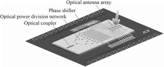
Fig. 1.1 Schematic diagram of photonic integrated optical phased array
loss. End-face coupler is a tapered structure based on mode conversion, and enlarges the size of the optical mode field in the waveguide, allowing for good matching with small core diameter optical fibers. To ensure as much light as possible is coupled into the waveguide, it is necessary to accurately cut the chip and polish its surface. Endface couplers have the characteristics of broadband and low polarization loss, making them ideal high-performance coupling devices. To improve coupling efficiency, lenstype or tapered optical fibers are often used to confine the light to a smaller mode size. However, the cost of lens-type or tapered optical fibers is much higher than that of a typical single-mode optical fiber.
The vertical coupling method is illustrated in Fig. 1.3. In vertical coupling, grating couplers are commonly used structures to couple the light from optical fibers to the waveguides in chips. Generally, a grating is designed on the silicon-based chip to form a grating coupler in the plane, which feeds the light from the external optical fiber into the chip, and then guides and focuses the light into the single-mode waveguide through a tapered structure. Grating couplers can efficiently couple large-size light spots into the waveguide, but they are very sensitive to the wavelength and polarization of light. To ensure coupling efficiency, the period of the grating should be adjusted when the wavelength and polarization state of the coupling light are changed. The vertical coupling method usually introduces a loss of 2–4 dB.
1.2
1.3
Fig.
Schematic diagram of end-face coupling
Fig.
Schematic diagram of vertical coupling
In practical applications, for device reliability, it is common to package the optical fiber with the coupler of the optical phased array chip.
1.2.2
Optical Power Distribution Networks
There are two types of optical power distribution networks: parallel and series. The parallel optical power distribution networks are unidirectional expansion structures, as shown in Fig. 1.4. In the parallel networks, multimode interference (MMI) power splitters (referred to as “MMI power splitters” hereinafter) play a crucial role in power distribution by leveraging the self-imaging effect. The parallel optical power distribution network consists of cascaded 1 × 2 MMI power splitters which divide the input light into two output paths. In the optical phased arrays, MMI power splitters with symmetric structures are usually applied to ensure the balance of phase and amplitude. However, due to their unidirectional scalability, the parallel optical power distribution networks are not suitable for two-dimensional array expansion.
Fig. 1.4 Schematic diagram of parallel optical power distribution networks
Fig. 1.5 Schematic diagram of series optical power distribution networks
On the other hand, the series optical power distribution networks are planar expansion structures composed of directional couplers (DC), as shown in Fig. 1.5.The directional coupler is typically composed of two adjacent waveguides with subwavelength spacing, and the coupling is induced by the transverse mode field of the waveguides. Light can be coupled from one waveguide to the other through a certain interaction length (coupling region), which can adjust the splitting ratio of the directional coupler. In optical phased array chips, the series optical power distribution network allows expansion in two orthogonal directions, making the entire power distribution network more compact. The directional coupler has advantages such as low transmission loss and easy control of power distribution ratio, but it is sensitive to polarization and has small tolerance for fabrication parameters.
The series optical power distribution networks are more suitable for large-scale two-dimensional optical phased arrays, but they require high precision in fabrication processes, which poses a significant challenge for chip fabrication. Therefore, the directional coupler with high robustness is an important direction for future research.
1.2.3 Optical Phase Shifters
Silicon-based optical phase shifters are core components in optical phased arrays for beam pointing and steering control which are based on waveguide structures to achieve the function of phase manipulation through changing the effective refractive
1.2CompositionofPhotonicIntegratedPhasedArrays7
index of the waveguide. Assuming that the change in refractive index caused by the silicon-based optical phase shifter in the silicon waveguide is Δn, the change in refractive index leads to a change in the phase of light propagating through the waveguide. The amount of the phase shift can be represented as Δϕ = 2π L Δ n /λ, where L is the length of the phase shifter. To obtain the phase change of π,the required length is L π = λ/2Δ n
1.2.3.1Types of Silicon-Based Optical Phase Shifters
Silicon-based optical phase shifters can be classified into two categories based on different phase shifting principles: electro-optic phase shifters based on carrier dispersion effect and thermo-optic phase shifters based on thermo-optic effect. The following section provides specific introductions to these two types of silicon-based optical phase shifters.
(1) Electro-optic phase shifters
The principle of carrier dispersion effects states that, under the influence of an external electric field, the concentration of free carriers in the material will change, resulting in corresponding changes in both the real and imaginary parts of the material’s refractive index, thereby achieving modulation of the optical field.
Silicon-based electro-optic phase shifters operate based on carrier dispersion effects, where the real and imaginary parts of silicon’s refractive index change with the variation of free carrier concentration in the active region of the silicon waveguide. The real part of the refractive index refers to the refractive index typically measured, while the imaginary part is related to the material’s absorption coefficient, determining the material’s losses. At the wavelength of 1550 nm, the change in silicon’s refractive index can be estimated based on Eq. (1.1) by the amount of free carrier concentration variation [11].
where Δ n and Δα are the changes in refractive index and absorption coefficient of silicon, respectively. Δ n e and Δ n h are the changes in refractive index of silicon caused by free electrons and free holes, respectively. Δαe and Δαh are the changes in absorption coefficient of silicon caused by free electrons and free holes, respectively. Δ N e and Δ N h are the concentration change of free electron and free hole, respectively.
Based on the ways of free carrier concentration variation, electro-optic phase shifters based on carrier dispersion effects can be further divided into carrier-injection type (p-i-n junction type) and carrier-depletion type (p–n junction type).
(a) Carrier-injection type: p-i-n (p-type/intrinsic/n-type) type. The p-type and ntype doping are separately conducted on two sides of a ridge waveguide and
Fig. 1.6 Schematic diagram of the carrier-injection-type (p-i-n type) electro-optic phase shifter under forward bias voltage
the waveguide region in the middle is undoped, namely intrinsic region. By applying a forward bias voltage to this structure, holes and electrons are injected into the undoped intrinsic waveguide region and the concentration of the free carriers in the waveguide increase, resulting in the variation of refractive index, thereby achieving phase modulation of light transmitted in the intrinsic waveguide region. This type of phase shifter belongs to the carrier-injection type and is also referred to as a p-i-n electro-optic phase shifter. The corresponding structural diagram is shown in Fig. 1.6
In a carrier-injection-type electro-optic phase shifter, the n-doped region and p-doped region are separated by an intrinsic region in the middle of the waveguide without any doping. Under forward bias voltage, free electrons and holes diffuse from the high concentration region to the intrinsic region, resulting in an increase in the concentration of free carriers in the waveguide. The injection of carriers into the intrinsic waveguide region through carrier diffusion has a relatively high efficiency. However, the injection rate is limited by the carrier lifetime, and the process of carrier diffusion also causes optical loss.
(b) Depletion type: p-n (p-type/n-type) type. In the carrier-depletion-type, the p–n junction is formed by slightly doping on both sides of the central line of the ridge waveguide. When a reverse voltage is applied to the ends of the p–n junction, a depletion region is formed in the p–n junction. During this process, the carriers in the waveguide can be extracted to establish an internal electric field and the concentration of free carriers in the waveguide is changed, leading to the variation of refractive index of the waveguide, thereby achieving phase modulation of the transmitted light. This type of phase shifter belongs to the carrier-depletion-type, also known as the p-n type electro-optic phase shifter, as shown in Fig. 1.7.
In the carrier-depletion-type electro-optic phase shifter, the carriers in the waveguide are extracted to form a carrier-depletion region under reverse bias voltage. This structure enables high-speed phase shifting without being limited by carrier lifetime. However, due to the narrow width of the depletion region, the phase shifting efficiency
Fig. 1.7 Schematic diagram of the carrier-depletion-type (p-n type) electro-optic phase shifter under reverse bias voltage
is relatively low, usually requiring a longer phase shifter to achieve a phase shift of π
The simulation model of the carrier-depletion-type electro-optic phase shifter is shown in Fig. 1.8, and the distribution of carriers in the electro-optic phase shifter under different bias voltages is shown in Fig. 1.9.FromFig. 1.9, it can be observed that when the external bias voltage is 0 V, the carrier concentration remains unchanged. When the external bias voltage is 4 V, carriers diffuse to the two sides of the waveguide and a carrier-depletion region is formed in the middle, resulting in the variation of refractive index, thereby achieving optical phase variation.
(2) Thermo-optic phase shifter
The principle of thermo-optic effect is based on the characteristic of refractive index variation with temperature in silicon material. By introducing a micro heater in the device, the external electric field energy is converted into thermal energy, thereby changing the refractive index of the material and achieving modulation of optical phase. Silicon is a material with a large thermo-optic coefficient, which is one order
Fig. 1.8 Simulation model of the carrier-depletion-type electro-optic phase shifter
Fig. 1.9 The distribution of carriers in carrier-depletion-type electro-optic phase shifters under different bias voltage
of magnitude higher than that of silicon dioxide. At a wavelength of 1550 nm, the thermo-optic coefficient of silicon material is expressed by [12]
where n is refractive index, T is temperature, and the unit of dn/dT is K 1
Due to the fact that the thermo-optic effect itself does not alter the imaginary part of the material’s complex refractive index, the thermo-optic phase shifter does not introduce additional losses.
Thermo-optic phase shifters are formed by designing various heating structures above or around the silicon waveguide, including regular metals and resistors formed by doping in waveguide. When a voltage is applied to the two ends of the resistor, electrical energy is converted into Joule heat and thus causes temperature increase in the silicon waveguide, which leads to the variation of refractive index, thereby resulting in phase of change of transmitted light in the waveguide. However, the thermal conductivity rate is slower than that of carriers, which limits the phase modulation rate of the thermo-optic phase shifters.
Figure 1.10 shows a schematic diagram of a single-sided doped thermo-optic phase shifter.
Figure 1.11 presents a thermal conduction simulation diagram of a thermo-optic phase shifter. The design layout and optical microscope photo of the thermo-optic phase shifter are shown in Fig. 1.12
The silicon-based optical phase shifters designed based on thermo-optic effect will face two problems: slow response and high-power consumption. Thermal conduction is slower compared to carrier movement. Both silicon material and metal electrodes are good thermal conductive materials, which result in heat dissipation and increased power consumption during the operation of the thermo-optic device. Currently, etching methods are employed to reduce thermal diffusion, which is an important means to reduce the power consumption of thermo-optic phase shifters. For example,
Fig. 1.10 Schematic diagram of a single-sided doped thermo-optic phase shifter
Fig. 1.11 Thermal conduction simulation diagram of a thermo-optic phase shifter
Fig. 1.12 Structure of thermo-optic phase shifter
adding air trenches at both ends of the phase shifter to isolate thermal conduction or etching the silicon substrate below the phase shifter to prevent heat dissipation from the silicon substrate are common methods of reducing power consumption.
1.2.3.2Performance Parameters of Silicon-Based Phase Shifters
The performance of silicon-based phase shifters includes five aspects: phase shifter size, phase-shifting efficiency, phase-shifting range, phase-shifting rate, and insertion loss. Reducing the size of phase shifters is beneficial for achieving large-scale expansion of optical phased arrays, and thus the size of phase shifters should be as small as possible. The phase-shifting efficiency is typically measured by the power requirement (P π ) for achieving a π phase shift. A smaller P π indicates a higher phase-shifting efficiency. The phase-shifting range refers to the amount of phase change that the phase shifter can achieve. In the design of optical phased arrays, a phase-shifting range of 0–2π is commonly required. The phase-shifting rate of a phase shifter represents the speed of phase variation and is related to its operating principle. The phase-shifting rate of electro-optic phase shifters based on the dispersion effect of carriers is usually high, reaching GHz. However, the phase-shifting rate of thermo-optic phase shifters based on the thermo-optic effect is relatively low approximately MHz, because of the limitation of thermal conduction speed. Insertion loss refers to the additional loss introduced into the optical path by the phase shifter. For electro-optic phase shifters, because carrier concentration can cause the absorption coefficient variation of refractive index, there will be absorption loss. By optimizing the geometric structure, doping concentration, and doping region size of the electro-optic phase shifter, insertion loss can be effectively reduced. For thermooptic phase shifters, as they can only change the real part of the refractive index of silicon material through temperature, there is no insertion loss.
In recent years, researchers have started to study the integration of other materials, such as germanium [13, 14] and lithium niobate microstructure modulators [15, 16], on the same wafer to achieve optical phase shifters with the advantages of high efficiency, low power consumption, miniaturization, and low insertion loss.
1.2.4 Optical Antenna Arrays
In photonic integrated phased arrays, light in the waveguide is directionally radiated into free space through the optical antenna arrays, and vice versa [17]. The optical antenna is the basic unit that forms the optical antenna arrays, and the geometric configuration, size, and arrangement of the optical antenna have a significant impact on the far-field radiation pattern of the optical antenna arrays.
Grating is an optical device that can produce periodic spatial modulation of the amplitude or phase of incident light, or both. The grating antenna modulates the
Fig. 1.13 Schematic diagram of two common dielectric grating antennas
amplitude and phase of the light fed into the waveguide using a grating, and then radiates the light into free space.
Silicon-based grating antennas are a kind of grating antennas fabricated on siliconon-insulator using silicon-based optoelectronic processes compatible with CMOS technology. They are widely used in photonic integrated phased arrays and can radiate the light transmitted in the waveguide into free space. Straight waveguide grating antennas and curved grating antennas are two common types of dielectric grating antennas, as shown in Fig. 1.13.
Straight waveguide grating antennas are formed by etching periodic grooves on the silicon waveguide. When the operating wavelength is 1550 nm, the length of the straight waveguide grating antenna is about a few hundred micrometers, and its width can be less than one wavelength. Due to its narrow antenna width, straight waveguide grating antennas are widely used in most one-dimensional optical phased arrays. The narrower width of straight waveguide grating antennas enables smaller spacing along the array direction, which allows for wide-angle beam steering. Due to their longer length, straight waveguide grating antennas are not suitable for use in two-dimensional optical phased arrays. The sizes of curved grating antennas on two dimensions are both a few micrometers thus the curved grating antennas are typically used in the design of two-dimensional optical phased arrays [18, 19]. To achieve a two-dimensional optical phased array with the properties of wide-angle steering, narrow beam radiation, and large-scale scalability, further research is needed on miniaturization and high-efficiency radiation of silicon-based optical antennas.
1.2.5 Control Circuit
The control circuit is an electrical circuit that provides voltage or current to the phase shifter in the optical phased arrays, and it is generally separated from the chip. The variation in beam phase can be achieved by adjusting the voltage or current values loaded on the two ends of phase shifter through the control circuit. The control circuit can be divided into two types: one is designed based on digital-to-analog conversion (DAC), and the other is designed based on analog switch.
Figure 1.14 shows a schematic diagram of the operating principle of a 128channel independently controllable control circuit based on digital-to-analog conversion. First, suitable digital-to-analog conversion chips are selected based on the phase shifting characteristics of the phase shifter, such as the required resistance, voltage/power, etc. Then, a field-programmable gate array (FPGA) chip controls 16 8-channel high-precision digital-to-analog conversion chips and the output independently controlled multiple voltage/current signals are allocated to the corresponding phase shifters in the optical phased arrays, whose accuracy and refresh rate depend on the resolution and conversion rate of the digital-to-analog conversion chip.
Figure 1.15 shows a schematic diagram of the operating principle of the control circuit based on analog switch chips. In Fig. 1.15, a square wave voltage reference signal, whose period and amplitude are controlled through the FPGA chip, is generated by a reference voltage module, and then modulated by an analog switch that can also be controlled through the FPGA chip. The generated square wave reference signal is then modulated by the analog switch, which is controlled by the FPGA chip. Finally, the output voltage value is determined by the modulated square wave reference signal, and the voltage accuracy depends on the operating frequency of the FPGA chip.
Fig. 1.14 Schematic diagram of a 128 independent control drive circuit based on DAC
Fig. 1.15 Schematic diagram of the operating principle of the control circuit based on an analog switch chip
Thanks to the development of CMOS technology, these control circuits can also be integrated into the chip. Monolithic integrated circuits for optical phased arrays with low power consumption have made significant progress, and control circuits and operational amplifiers can also be integrated into the same chip. Therefore, control circuits with more channels will be realized by a single microelectronic chip, providing technical supports for the development of larger-scale photonic integrated optical phased array chips.
1.3 Beam-Steering Principles of Optical Phased Arrays
Optical phased arrays can be classified into two types according to beam steering mode: one-dimensional steering arrays and two-dimensional steering arrays. The one-dimensional steering arrays refers to an array that performs beam steering in one direction (azimuth or elevation); the two-dimensional steering arrays refers to an array that can simultaneously perform beam steering in both azimuth and elevation directions. Since the principles of the one-dimensional steering arrays and the twodimensional steering arrays are similar, the following will take one-dimensional steering arrays with uniformly distributed antennas as an example to introduce the beam steering principle of optical phased arrays.
The principle of one-dimensional optical phased arrays is shown in Fig. 1.16 For different far-field angles θ , there will be a path difference of d sinθ between the emitted optical fields of the antennas in the array, which corresponds to a phase difference of 2π λ d sin θ . The additional phase difference of the emitted optical field
Fig. 1.16 Schematic diagram of one-dimensional optical phased arrays
from the n-th antenna at different angles is denoted as ϕn (θ ), and it can be expressed as
where λ represents the wavelength, d represents the spacing between the antennas, and θ represents the beam deflection angle, with n = 0, 1, 2, ….
When the amplitude of the emitted optical field from each antenna is equal and the initial phase is 0, the emitted optical field E n (θ ) from each antenna can be described as
where E 0 is the amplitude of the optical field.
By substituting Eq. (1.3) into Eq. (1.4), there is
When the initial phase of each antenna is set to ψ n ,Eq. (1.5) becomes
When the phase difference between two adjacent antennas Δϕ satisfies
The emitted optical fields from different antennas will interfere constructively. Here, k represents the interference order. By substituting Eq. (1.7) into Eq. (1.6), there is
where Δψ n represents the initial phase difference between the (n + 1)-th antenna and the n-th antenna, Δψn = ψn+1 ψn
For the + first-order radiation (k =+ 1), Eq. (1.8) can be simplified to
It means that by appropriately adjusting ψn , the radiation peak of the radiated optical field at the angle θ can be observed. In other words, by adjusting the phase of the antenna, the far-field beam steering can be controlled. In fact, by controlling ψn , not only can a single radiation peak be formed in the far field, but also complex radiation patterns can be achieved.
The antennas in the optical phased arrays are used to radiate and receive energy. In order to achieve beam steering without grating lobes, the distance between adjacent antennas d should satisfy
where λ represents operating wavelength, and θ max represents the maximum steering angle.
It can be seen from Eq. (1.10) that the distance between adjacent antennas d is less than one wavelength, and the beam steering range will increase as d decreases. In order to obtain an optical phased array that can perform wide-range steering, it is necessary to shorten the distance between antennas and design miniaturized antennas.
1.4 Relationship Between Optical Phased Arrays and Microwave Phased Arrays
The principles of beam steering in optical phased arrays and microwave phased arrays are similar. Both optical waves and microwaves are electromagnetic waves. However, due to their significantly different frequencies, there are two main differences between optical phased arrays and microwave phased arrays.
(1) In terms of antenna form and material, the wavelength used in optical phased arrays for optical communication is 1550 nm, corresponding to a frequency of 193.5 THz. As a result, optical antennas are much smaller in size compared to microwave antennas, requiring high precision in fabrication and presenting significant implementation challenges. Currently, optical lithography is predominantly used for fabrication. The main form of antennas is chips. Microwave antennas come in various forms and there are many materials to choose from. The materials used for optical antennas must consider the requirements of lithography processes, hence the selection of materials primarily focuses on silicon-on-insulator, with the use of gratings as the primary form for the antennas.
(2) In terms of antenna characteristic test, the test methods used for microwave antennas, such as far-field, near-field, or compact range test in microwave anechoic chamber, cannot be applied in optical antenna test. Therefore, it is necessary to establish a dedicated test system for conducting the test of optical antenna characteristics.
1.5 Main Parameters of Optical Phased Arrays
Optical antenna is a device that efficiently converts free radiated energy into guided wave energy, and vice versa. It is characterized by two main parameters of port characteristics and radiation characteristics.
1.5.1 Port Characteristics of Optical Antennas
In circuit theory, impedance Z is defined by the ratio of voltage V of the power source to current I, i.e., Z = V/I. This definition assumes that the power source is connected to the antenna via a current-carrying transmission line. However, optical antennas are usually fed by localized optical emitters rather than currents. Therefore, the definition of antenna input impedance needs to be adjusted. The concept of local density of electromagnetic states (LDOS) is introduced, which can be expressed by the Green’s function tensor ↔ G and explains the energy dissipation of a dipole in an arbitrary inhomogeneous environment. Single emitters, such as atoms and molecules, are quantum objects themselves, so strictly speaking, they should be treated using quantum mechanics. However, most two-level systems reside in the ground state can be represented using classical dipoles. Therefore, the quantum mechanical description of a two-level atom is discussed firstly and then establish a connection with the classical representation. Located at the position of ro , the total decay rate of a two-level quantum emitter coupled weakly with the antenna can be expressed with the Fermi’s golden rule
where ⟨ g | | ˆ p| |e ⟩ represents the transition dipole moment between the excited state |e ⟩ and ground state | g ⟩ of the emitter, ω is the transition frequency, è is the reduced Planck constant; ε0 is vacuum dielectric constant; ρ p ( r o ,ω ) is the partial density of electromagnetic states, which can be expressed as
where np represents the unit vector pointing in the direction of p and c is the speed of light in vacuum.
The Green’s function in Eq. (1.12) is indirectly defined by the electric field E at the observation point r generated by a dipole p located at ro
The total local density of electromagnetic states is obtained by assuming that the quantum emitter has no preferred dipole axis, and the average value of Eq. (1.12) over different dipole orientations is
where Tr represents the trace.
Therefore, the excitation state lifetime τ = 1/[ of the quantum emitter is determined by the Green’s function ↔ G of the system, in which the emitter is embedded. The local density of electromagnetic state indicates that the presence of the antenna and is a measure of the antenna characteristics. In free space, it can be obtained that
Substituting it into Eq. (1.11), it is obtained that
A classical dipole p (a point source current located at ro ) is applied to represent a quantum emitter. According to Poynting’s theorem, the power dissipated by a time-harmonic system is
where V is the source volume, j is the current density, E represents the electric field. The current density j can be expanded in a Taylor series around some origin ro , and to lowest approximation can be written as
where p is the dipole moment, δ is Dirac delta function.
Substituting Eq. (1.16) into Eq. (1.15) yields
In Eq. (1.17), the electric field is generated by the dipole and evaluated at the dipole’s origin. According to Eq. (1.13), the field is expressed in terms of Green’s function, and the dissipated power is that
Using the dipole radiation optical power in free space P
, the local density of electromagnetic states in terms of the normalized power radiation are
Through Eq. (1.11)toEq. (1.18), there is
The ratio of power dissipation to transition rate can be expressed using the dipole moment. In circuit theory, the impedance of an antenna can be determined based on dissipated power as Re( z ) = P / I 2 . Since a driving dipole instead of a physical current, it is easier to define Z based on current density, which is
The real part of the impedance of an antenna Re( z ) is related to the local density of electromagnetic state, and its unit is ohms per area. The impedance Z depends on both location ro and the orientation np of the receiving and transmitting dipole. The imaginary part of impedance accounts for the energy stored in the near field.
The relationship between the reflection coefficient of the antenna port γin and the impedance of the antenna
where Z 0 is the intrinsic impedance of the device feeding light into the antenna. Return loss is the ratio of reflected power Pr to incident power Pi , expressed in decibel as
1.5.2 Radiation Characteristics of Optical Antennas
As an electromagnetic wave receiver and transmitter, the radiation characteristics of optical antenna primarily include far-field radiation pattern, efficiency, directivity coefficient, and gain. Figure 1.17 illustrates the far-field radiation pattern of an optical antenna, which consists of mainlobe and sidelobes. The far-field radiation pattern of an antenna generally contains multiple lobes, with the largest lobe in the radiation direction referred to as the mainlobe, the lobe located directly behind the mainlobe known as the back lobe, and the other lobes referred to as sidelobes. The sidelobe level (SLL) is the ratio of the maximum power value of the sidelobes to the maximum power value of the mainlobe. In space laser communication, it is typically desired to have low sidelobes, with the mainlobe generally aligned towards the communication target.
Fig. 1.17 Far-field radiation pattern of an optical antenna
The power P in Eq. (1.18) represents the total dissipated power (input power), composed of radiated power P rad and the dissipated power converted into heat and other channels (P loss ). The radiation efficiency εrad of the antenna is defined as
According to Eq. (1.17), the power P can be obtained by calculating E at the dipole position. The calculation of P rad requires the evaluation of the energy flux through a surface enclosing the dipole and the antenna.
The intrinsic quantum efficiency of the emitter is defined as
where superscript o represents the absence of an antenna, and P o intrinsicloss represents the intrinsic loss of the emitter.
According to the definition of ηi ,Eq. (1.24) can be expressed as
/ P o rad
/ P o rad + Pantenna
For an emitter without intrinsic loss, i.e., ηi = 1, the antenna will reduce efficiency. But for an emitter with low ηi , it can effectively improve the overall efficiency.
To elucidate the angular distribution of radiation optical power, a normalized angular power density p (θ, ϕ ) is defined, also referred to as the radiation pattern
where θ , ϕ are the pitch angle and azimuth angle in spatial coordinate, respectively. The directivity coefficient D of an antenna is a metric of its ability to concentrate radiation energy in a specific direction, corresponding to the angular power density relative to a hypothetical isotropic radiator.
D (θ, ϕ ) = 4π Prad p (θ, ϕ ) (1.28)
When the direction (θ, ϕ ) is not explicitly specified, it usually refers to the direction of the maximum directivity coefficient, that is
Dmax = (4π/ Prad ) Max ( p (θ, ϕ ))
Another random document with no related content on Scribd:
and I’ll bear my share of the expense. I suppose you feel the same way, Bragden?” he added.
Bragden nodded his head.
“That’s the way I feel about it,” he agreed. “But when the thing happens, I am going to be out of town. I’ll help bear whatever expense there may be in carrying out the plan.”
“Leave me to hold the bag, eh?” Hankinshaw sneered. “Well, I didn’t expect anything else,” he added. “You have always looked to me for the rough stuff, but let it go at that. I’ll take a chance; play a lone hand.”
Thompson and Bragden chose to ignore the slur about their courage, and a conference followed on ways and means. When the gathering broke up it had been agreed that Hankinshaw’s nefarious scheme should be put into effect on the first night that conditions were favorable.
All unaware of their enemies’ plotting, Tom and his companions were exceedingly busy with plans for getting the oil to market. They had already ordered several miles of eight-inch pipe, which they intended to run to Copperhead, the nearest town on the railroad. The time of delivery was uncertain, however, and until the pipe arrived, there was not much that could be done toward developing the well. They had secured a right-of-way for the pipe line over the adjoining farms, and were now anxious to get the oil running.
“It won’t take us very long to lay the line, once we get the pipe,” remarked Tom. “If only we had been absolutely sure that we were going to strike oil, we could have ordered it months ago, and had it here all ready and waiting now.”
“Bless my thick skull! that’s true, Tom,” exclaimed Mr. Damon. “But none of us are prophets, and eight-inch pipe isn’t the cheapest thing in the world to buy. That’s one of the things we simply had to let go until we knew we had the oil to put through it. We don’t need to worry, anyway. The main thing is that we’ve got the oil, and a week or so’s delay won’t hurt us. It will give us a chance to rest up.”
Luckily for Tom and his friends, they did not have to have pumping stations, as their well was on comparatively high ground, and there was a continual slope from there to Copperhead. All they had to do was to run their eight-inch pipe line to the town and empty
it into a concrete tank. This tank had already been started several days before, and they expected to have it completed by the time they got the oil line connected up.
Urgent telegraph and telephone calls hurried up shipments of pipe, and in a few days it began to come in. Tom directed the laying. The men all liked the young inventor and worked willingly and untiringly at his bidding, but at best it was slow work getting those four miles of pipe laid. In spite of his desire for speed, Tom would not allow any careless work, and each joint had to be made to his satisfaction before another could be bolted up.
They laid the pipe in shallow trenches and covered it a few inches deep with dirt. Length after length, it grew steadily.
It looked like plain sailing then, but for some unexplainable reason, after they had started the line from the well, the valve started to leak. Probably the tremendous pressure of the oil behind it had opened up some little flaw in the gate or seat, and oil started coming through—not in any great quantity, to be sure, but still there was a constant stream, which ran through the pipe and made it difficult to join the sections together and kept the men constantly dripping with the thick brown liquid.
Tom would not admit it, but he was worried. He knew that the leak might get worse, that the valve might give out altogether and release the imprisoned oil. His first act was to telegraph for a new valve. After that, he gave orders to have the new pipe line disconnected close to the well. This stopped the oil running through the line, but of course it ran out into the ground instead and trickled down the hill in every direction. However, the leakage was not large as yet, and if it got no worse would not be a serious thing. It meant some loss of oil, but it would be for only a few days, until they could get the line connected to the tank in Copperhead.
“Bless my forebodings! I don’t like it, just the same,” said Mr. Damon, with a shake of his head. “It takes away my confidence, Tom. If that valve can leak a little, it can leak a lot, and I expect almost any old time to hear it let go.”
“It’s possible,” admitted Tom. “No use worrying about it, though. I don’t like to see our good oil going to waste any more than you do,
but I guess it won’t amount to very much, after all. There’ll be plenty left in the well, Mr. Damon.”
“Dat stuff doan look like oil, nohow,” said Rad, who was an interested spectator of all that was going on. “Dat looks mo’ lak good ole molasses to me.”
“Well, maybe it is,” said Tom. “Taste it and see, Rad.”
Rad did as he was bidden, but instantly made a terrible face and looked reproachfully at the young inventor.
“Is it molasses, Rad?” asked Tom, trying hard to keep a straight face.
“No, sah, dat ain’t no molasses. It’s de worst stuff dat dis niggah evah tasted, an’ Ah doan want no mo’ of it. Guess Ah’ll have to take a good swig o’ watah to git de taste outen ma mouf,” and Rad made for the water bucket.
“Live and learn,” laughed Mr. Damon, his anxiety over the leak forgotten for the moment. “Bless you, Rad, things aren’t always what they seem.”
“Ah believes you-all now, Mistah Damon,” said the old negro, as he ruefully scrubbed at his lips in an effort to get rid of the taste. “Nex’ time Ah lets some odder fool niggah do de samplin’.”
That night at the farmhouse, while the others of the company were chatting about the events of the day, Mr. Damon stepped to the window to take note of the weather, as he was accustomed to do. As he reached the window he gave a startled exclamation.
“Bless my fire insurance!” he cried. “There’s a big fire. Looks as though it might be in Copperhead, only it’s hardly far enough away for that.”
At his words, the others jumped up and crowded to the window.
“I should say it isn’t as far as Copperhead!” ejaculated Tom. “Why, that fire is close, and getting closer every minute!” and he dashed out of the house, followed by the others.
In the north was a lurid glare, growing brighter every moment. A fresh breeze blew toward them, bearing a stifling smoke, with now and then a floating spark. The long, dry grass was on fire, and, blown by a lively breeze, was rapidly approaching the oil well!
CHAPTER XXIV
FIGHTING THE FIRE
“T�� ����!” shouted Tom. “It’s coming toward the well!”
Terror gripped at the hearts of all. The men stood for an instant as though paralyzed. Carol wrung her hands in anguish.
“With this wind blowing, nothing can stop it,” groaned Mr. Damon, his face white with excitement.
“But even if it gets that far, the well is capped!” exclaimed Ned, catching at a shred of hope.
“It’ll catch fire just the same,” said Tom, as he remembered the leaking gate valve and the oil-soaked hillside. “Once let the flames begin to lick round that casing, and there’ll be a tremendous explosion. Don’t let’s fool ourselves. We’ve got to stop it—got to stop it! Carol, you run to the ’phone. Call up the neighbors. Call up Copperhead. Get all the fire-fighters you can. You men come with me.”
Hankinshaw and his gang had done their work well. The night was an ideal one for their project, the wind being strong and from the north where there were dense thickets and many trees to furnish fuel for the fire, which was now advancing at terrifying speed.
“Everybody get shovels,” yelled Tom. “I’ll get the men up,” and he dashed toward the cabin where the drillers slept. Usually, Koku slept there too, and Tom hoped to find him, for he knew what the giant’s great strength and tireless endurance were worth in an emergency.
Luckily Koku was in the cabin with the men, but it was almost impossible to get him awake. The others had all rushed out with shovels and axes before Tom finally shook him into consciousness.
“What’s matter?” he muttered, as he scrambled sleepily to his feet. “Time get up?”
“You bet it is—high time,” replied Tom, and the excitement in his voice effectually aroused the faithful giant. “The woods to the north of the oil well are on fire, and the flames are coming toward us fast. We’ve got to put that fire out, Koku.”
“I do that,” declared Koku confidently
“Get a shovel and follow me,” ordered Tom. “You might take an axe along too,” he added. “The only chance we’ve got is to clear a space ahead of the flames that they can’t jump over. If we can do that, we may save the well yet,” and he and Koku started at a fast run toward the oncoming flames.
The fire had not yet reached the oil belt, but it was not over a mile from it when the young inventor and his faithful giant arrived on the scene. Everybody that could handle a shovel or an axe was there, but they were working without leadership until Tom arrived. He took control at once, and in a few minutes everybody knew just what he was expected to do.
By this time the heat of the fire was intense, and the smoke enveloped those fighting it in a stifling cloud. Hot sparks and embers floated over their heads, and threatened at any moment to kindle new fires nearer the oil well. Tom detailed three of the drillers to watch for these incipient fires and smother them or beat them out before they got serious. Ned and Mr. Damon, together with the rest of the drilling gang and such of the neighbors as had come to help, he put to work digging ditches and clearing the ground in the path of the approaching flames of its dried underbrush, while he and Koku set about chopping down some of the trees that grew on the hillside. They were not large trees, scarcely more than saplings in fact, but there were a great many of them.
“Now, Koku,” shouted Tom, “work as you’ve never worked before.”
“Me do,” answered the giant, as he tightened his hold on the axe.
Tom himself was an expert at wielding an axe, and he swung with a tireless stroke that soon showed results, but for every sapling that he brought down Koku felled two. In the red glare of the oncoming fire the giant worked like a demon, his great muscles swelling and knotting as he swung the blade of his axe in gleaming circles. The heat increased until it became so unbearable that everybody else had to fall back, but he hardly seemed to feel it. He kept at work until the fire was almost on top of him, and Tom yelled to him to come back. But by that time they had cut a long swath along the side of the hill between the fire and the well. Other workers had pretty well
cleared up the underbrush and drawn the bulk of it back, apparently out of the reach of the oncoming flames.
But they had reckoned without the wind, which blew strongly and fanned the fire into a fury that recognized no check. As it reached the edge of the cleared space it died down slightly while it ate along the edge as though it were endowed with intelligence and was seeking out the easiest place to cross. The scorched and weary fire-fighters leaned on their tools and waited with nerves tense to see if their efforts had prevailed. Had the night been still, the red enemy would have been conquered then and there from lack of fuel to feed upon, but the wind rose until it reached half a gale and carried on its wings blazing leaves and twigs that alighted on the far side of the cleared space. Here the fire found fresh fuel to feed upon, and resumed its devastating march toward the oil well.
Some of the fire-fighters were ready to throw down their tools and admit defeat. They had seen the fire demon at work before, and they knew how hard it was to bar his progress. Had it been left to them, they would have given in to what they considered the inevitable, and accepted defeat. But Tom, like a famous American commander, had “just begun to fight.”
“Come on up farther, and we’ll try again!” he yelled. “The wind is dying down a little, and this time we may stop it.”
But this time he resorted to a stronger force than mere human labor. In a shack not far from the well was stored some nitroglycerine, which they had bought when it seemed as though they might have to explode it to strike oil. It was not needed at that time, but now the thought of it flashed through Tom’s mind, and he resolved to try it. He figured that by exploding the powerful nitroglycerine he could plough up a deep and wide trench that might effectually prevent the further progress of the fire.
“Come on, Koku!” he shouted, “I’ve got a job for you.”
Followed by his giant retainer, he set off for the storage shack. When they reached it, Tom reached in his pocket for the key to the padlock. He fumbled about, but the key was gone—lost in the mad activities of that lurid night.
“We’re up against it now, Koku!” exclaimed the young inventor, in desperation. “We’ve got to get into that shack, but the key is lost,
and that’s a strong padlock. How are we going to do it?”
For answer, Koku seized the padlock and, placing his foot against the door jamb, pulled until his powerful muscles stood out in ridges. There came a screech of nails being drawn through wood, padlock and hasp came flying off the door, while Koku staggered backward and almost fell from the force of his own exertions.
“Good enough!” exclaimed Tom. “Now, Koku, this is dangerous stuff to handle. If we fall with it, they’ll never be able to find the pieces. Are you game to take the chance?”
“What you tell me, I do,” replied Koku calmly
Each took all of the explosive he could carry and started back toward the fire. It was a terribly dangerous journey, as a fall would spell disaster. The fire gave such a light, however, that they could see as clearly as in daytime, and it was not long before they had the high explosive in place in front of the approaching flames. Then all ran to a safe distance, while Tom set the charge off.
There was a terrific roar, and a cloud of gravel, chips, and other debris went flying through the air. When the smoke cleared away, the fire-fighters saw that they had a broad trench for hundreds of feet in both directions, with sand and gravel heaped up in great piles along its length.
It looked as though this would surely stop the fire, and for a time it seemed as though their hopes would be justified. The fire hesitated, and died down until it seemed to be only smouldering.
But suddenly a burning tree, almost uprooted by the explosion, toppled across the ditch, and before Tom or any of the others could get to the spot, the fire had taken hold again, and was rapidly spreading. All their work was wasted, and the fire was a good deal nearer the well than when they had started!
Still they fought on doggedly, blistered and smoke-begrimed. Carol and other women passed up and down the line with coffee and sandwiches. Tom and Ned were here, there and everywhere, working feverishly and cheering on the men.
“We’re goners though, old boy!” groaned Ned.
“Never say die!” panted Tom, feigning a confidence he was far from feeling. “We’ll beat it yet.”
But when the morning came, the fire was still gaining—gaining only by inches now in the desperate battle—but gaining. The gallant host of weary men still fought on, but they fought like men at bay, looking into the fiery eyes of doom!
CHAPTER XXV
VICTORY
T�� ��� as near despair as he ever permitted himself to be. It looked as though the well was doomed. Even though it was capped, he knew that if it became the center of those devouring flames the steel would melt and the fire come in contact with the oil. And this meant a catastrophe so appalling that none could foresee the consequences.
But it was not in his nature to quit, and he cudgeled his brain desperately to find some way of averting the calamity. Suddenly a thought came to him like an inspiration.
“Come along, Ned. You too, Koku,” he shouted. “Mr. Damon, you keep the men working.” And without waiting for an answer the young inventor started on a run for the Winged Arrow.
Ned and Koku were close on his heels when he reached the giant plane. Fortunately, it was always kept in readiness for instant flight.
“Jump in!” he shouted to his companions, setting the example. He started the engine and the plane soared into the air and turned its nose toward Copperhead.
“Ned,” he said, “those fire bombs of ours! We shipped a lot of them to Southern cities. Which is the nearest town that has some? Think quickly, old boy.”
Ned caught on to Tom’s idea instantly.
“We sent a lot of them to Dallas,” he replied. “A big shipment went to Wesson and Robbins of that place. No doubt they have some of them on hand.”
“Good!” cried the young inventor “There’s a flying field on the outskirts of that town. I’ll let you down as near to Copperhead as possible. You rush to the office and get Wesson and Robbins on the long distance ’phone. Tell them to have a dozen of them at the flying field when I get there. I won’t wait for you, but put right out for Dallas on the chance. It’s nearly a hundred miles, but the Winged Arrow will
make it in an hour You hotfoot it back to the farm—get an auto or a horse—and take charge there till I get back. Keep the fire down as much as you can.”
“I’ll do it,” said Ned. “Great head, old boy. Good luck.”
In two minutes more they were close to Copperhead. Tom swooped down, let Ned get out, and then with a whiz and a whirr rose and made for Dallas.
The fire bombs to which Tom referred were of his own invention and had achieved such remarkable results that they had been adopted by fire departments all over the United States. They contained chemicals of which Tom held the secret that were of wonderful efficiency in extinguishing fire. Tom had demonstrated their value on many occasions, notably when he had saved a great office building in a city not far from Shopton by dropping from an airplane the bombs containing the chemicals directly on the apparently doomed building, as narrated in the volume of this series entitled: “Tom Swift Among the Fire Fighters.”
Tom’s mind was a tumult of stormy thoughts. Would Wesson and Robbins have the bombs? Would Ned be able to get his message through in time? Even if these things went smoothly, would he get back before the flames reached the well, making all his efforts go for naught?
But he did not let these thoughts take his mind off the plane. This was vital. If the plane broke down, all hope would be gone.
So he urged and coaxed the plane along, pressing it to the utmost speed he dared. This was a race—a race against fire—a race against time!
Before long he could see the towers and steeples of the city in the distance. He neared it rapidly, straining his eyes to catch sight of the flying field with its white signals for the guidance of airmen.
Yes, there it was, and luckily on this side of the city. He swooped down and made his landing in close proximity to a loaded truck that he guessed might contain the bombs.
As he jumped out and ran toward it, he saw with a thrill of exultation the name of Wesson and Robbins on the truck. Ned had got the message through. Good old Ned!
It was the work of only a few minutes with the aid of Koku and the two burly truckmen to get the bombs transferred to the plane. And Tom blessed his stars that he had brought the big plane South with him instead of one of his smaller airships.
With a hurried word of thanks, Tom jumped into his seat and started on his homeward journey. On the way he instructed Koku to hold himself in readiness to drop the bombs when he should give the word.
In less than an hour, which seemed to him like an eternity, he had passed Copperhead. He had been straining his ears for the sound of an explosion and thanked heaven when it failed to come. But the angry glare that grew more vivid as he approached told him that the fire demon was still trying to get at its prey.
In another minute or two he was circling above the Goby farm. Beneath him he could see men running for cover. He knew that Ned had seen him coming, and had ordered the men to disperse so that they would escape danger from the falling bombs.
He could see the flames eating their way ruthlessly toward the well, and only a few yards away from it. He steadied the airplane as nearly above the flames as possible. Koku was holding one of the bombs in readiness.
“Now!” cried Tom, and the giant dropped the bomb.
It fell about a hundred feet from the well, right in the midst of a seething caldron of flame.
The effect was instantaneous. The fire died out in a twinkling. For a wide area the red turned to black. Even the smoke disappeared and was replaced by a cloud of vapor that was slowly dissipated.
They were too high to hear the cheers that rose from the firefighters looking on, but Tom could see them waving their hats and hands and jumping up and down like mad.
Koku held another bomb poised aloft, and again at a signal from Tom he let it fall. It struck in a different place this time, but with the same result. In the vicinity where it struck, the flames went out as though some wizard had turned a switch and extinguished them.
Several times this was repeated until Tom saw that the flames had been definitely conquered. Only little scattered patches were
left, and these could easily be put out by hand. The young inventor had won the fight!
Only when he was sure of this did he swoop down to his usual landing place and get out, to be overwhelmed with cheers and handshakings and thumpings by Ned and Mr. Damon and the host of grimy fire-fighters with blackened hands and faces, all of them almost crazy with joy. What little was left to do was quickly done, and before long every spark had been extinguished. The well was saved!
It was a tired but happy group that sat in the living room of the Goby farmhouse that night. Mr. Goby’s face was beaming. Mr. Damon was blessing everything and everybody.
In the kitchen, Koku was boasting of his exploits and Rad was belittling them, the only thing on which they agreed being that although there were some great men in the world, there was none so great as “Marse Tom.”
Suddenly the door of the living room was flung open and a stalwart young fellow rushed in.
Every one looked up, startled by the unceremonious irruption. Carol sprang to her feet with a joyous cry, ran toward the newcomer, and threw her arms about his neck.
“Oh, Father!” she cried, “it’s Hitt! It’s brother! He’s come back to us!”
The blind man tried to rise, but fell back in his chair. The next instant his son and daughter were beside him and he folded them in his arms.
Tom rose, followed by Ned and Mr. Damon, and tiptoed into the adjoining room, leaving the reunited family to themselves.
But they were called back before long, and Tom and Ned were overwhelmed with thanks by Hitt Goby for the way they had rescued him from death.
“And he’s going to stay at home with us now for good,” announced Carol happily
Probably there was no happier home in Texas that night than the Goby farmhouse. Carol was in the seventh heaven of delight, her father’s face was radiant, Hitt Goby was joyous. The happiness of the others, while perhaps not so rapturous, was not less real.
And Tom among the intervals of talk and laughter was thinking of —Mary. He was counting the hours before he could be back with her and share with her his triumphs.
But before that wished-for moment could be reached, there were many things that imperatively claimed his attention. He had a fortune in his well and in the other leases and purchases he had made in connection with his associates. And there was another fortune, and perhaps a bigger one, in that marvelous drill, whose achievements had so interested the captains of finance that offers for the patent rights were beginning to flow in on him from all directions. The first, and so far the best one, was from the company represented by Mr. Blythe. Some of these things had to be attended to by Tom personally and at once, but whatever was possible he left to Ned and Mr. Damon to adjust.
He had put inquiries on foot to find out the source of the mysterious fire, and one day was apprised by Judge Wilson that Hankinshaw had been arrested. One of the confederates he had employed had been arrested for another offense, and with the hope of getting a lighter sentence had revealed the incendiary plot. Warrants were out also for Thompson and Bragden, but those worthies had already put half a continent between them and their pursuers and had not yet been apprehended. Hankinshaw, however, was less lucky, and some time later was tried and sent to prison for a five-year term.
“That’s one rascal that’s got his deserts,” remarked Tom.
“Not by a jugful!” exclaimed Ned. “He ought to have got twice as much.”
“Bless my lockstep!” snorted Mr. Damon. “They should have sent him up for life.”
“Oh, well, who cares?” Tom summed it up. “The main thing is that he didn’t get away with it. We won out. The whole thing’s been a great adventure.”
The Goby family could not get over what Tom had done for them.
“You’re a friend worth having,” was the way Hitt Goby expressed himself. “If it wasn’t for you, I don’t know where I’d be to-day. Most likely in the cemetery.”
“Oh, perhaps not as bad as that,” returned the young inventor modestly.
“And see what he has done for the whole family!” cried Carol, her eyes sparkling. “Why, this oil is going to make Father rich.”
“It’s making us rich, too,” said Tom.
“But think of what might have happened if we had put ourselves in the hands of those rascals,” came from Mr. Goby. “I tell you, Tom Swift, you are one young man out of a million!”
“The best ever,” murmured Hitt. “I’ll bank on him every time.”
“So will I,” laughed Ned.
Tom could not stand all this praise, so he merely smiled and turned away. Yet it pleased him greatly.
Other adventures are still in store for Tom Swift, but these must be kept for another volume. For the present we will leave him with his great success in making a wonderful improvement in oil-well machinery and bringing in his Great Oil Gusher.
THE END