Louver Inspiration
Louvre, Abu Dhabi
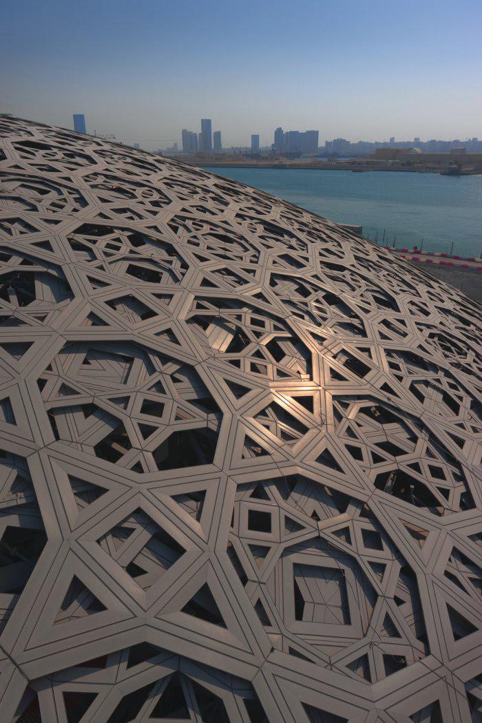
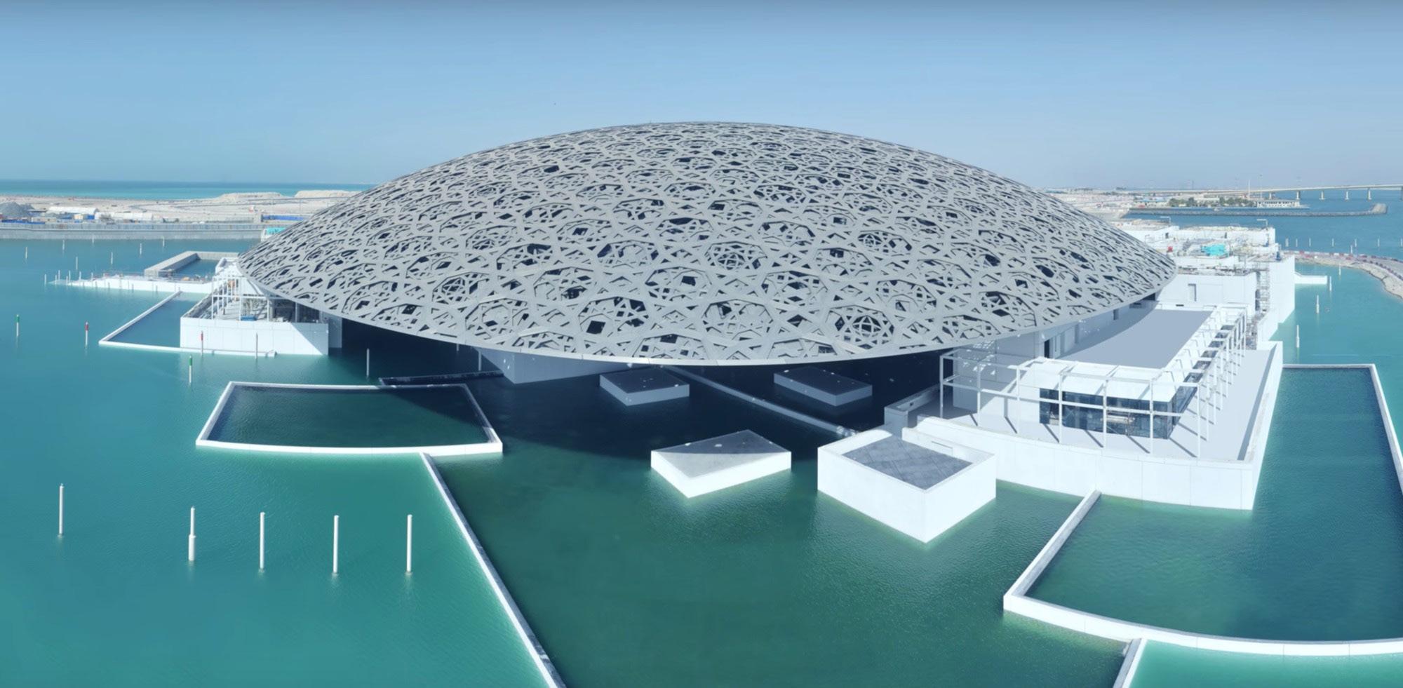
The inspiring beauty and architectural splendor of the Louvre in Abu Dhabi stands as a remarkable symbol of design and innovation.
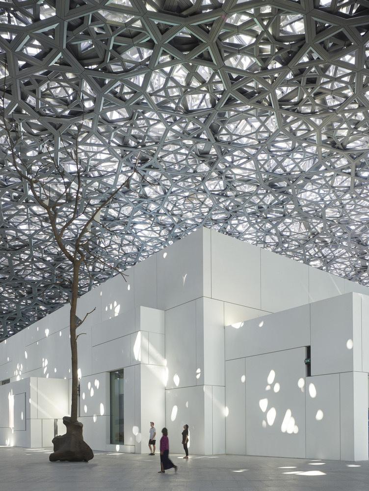
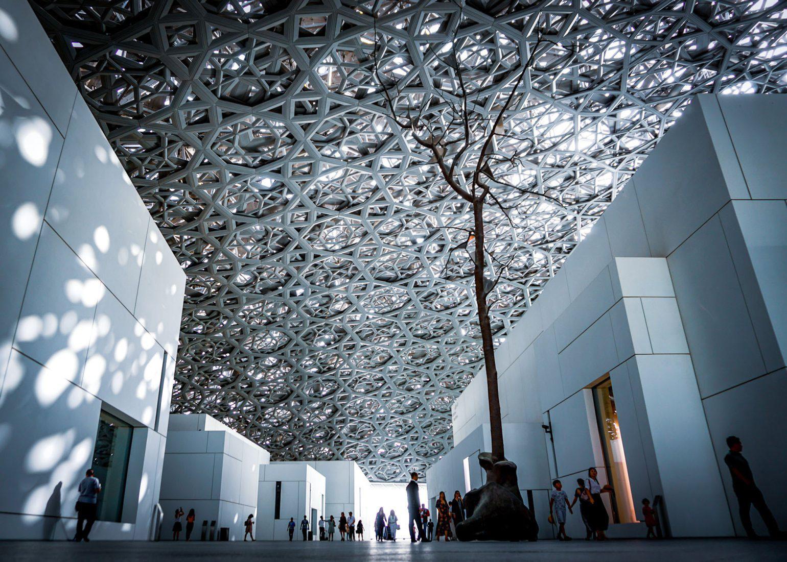
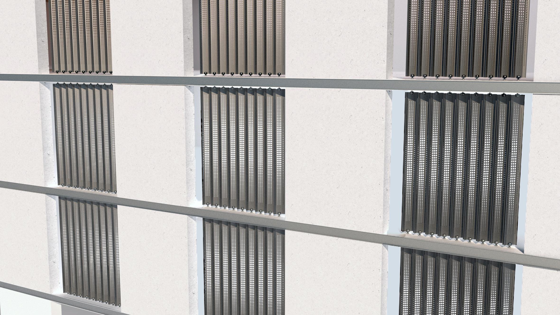
The roof of the Louvre is the primary inspiration for the new louver design proposal. The intricate geometric patterns present in the roof captivated my attention and served as a basis for the louver design. The interplay of sunlight and shadow produced by the roof creates a visual impact, giving an overall aesthetic appeal.
The process of crafting the highly detailed lattice roof involved extensive research and rigorous testing over the course of several years. The outcome is an elaborate dome consisting of nine layers, featuring four tiers of uniquely engineered and interconnected stars for both upper and lower cladding.
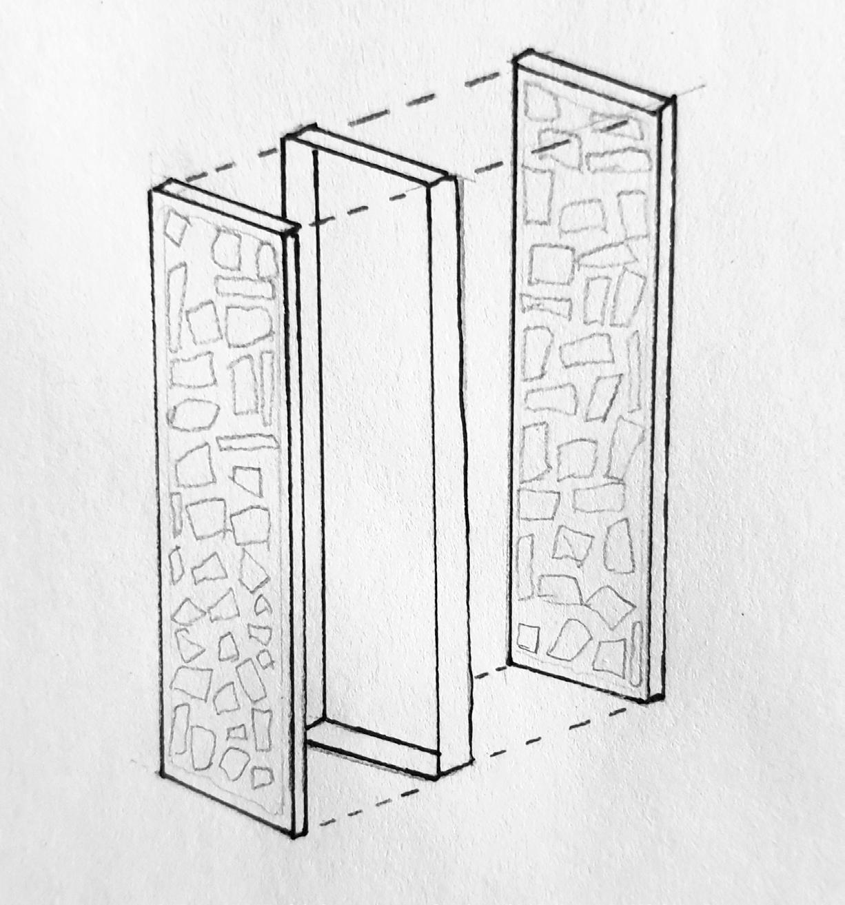
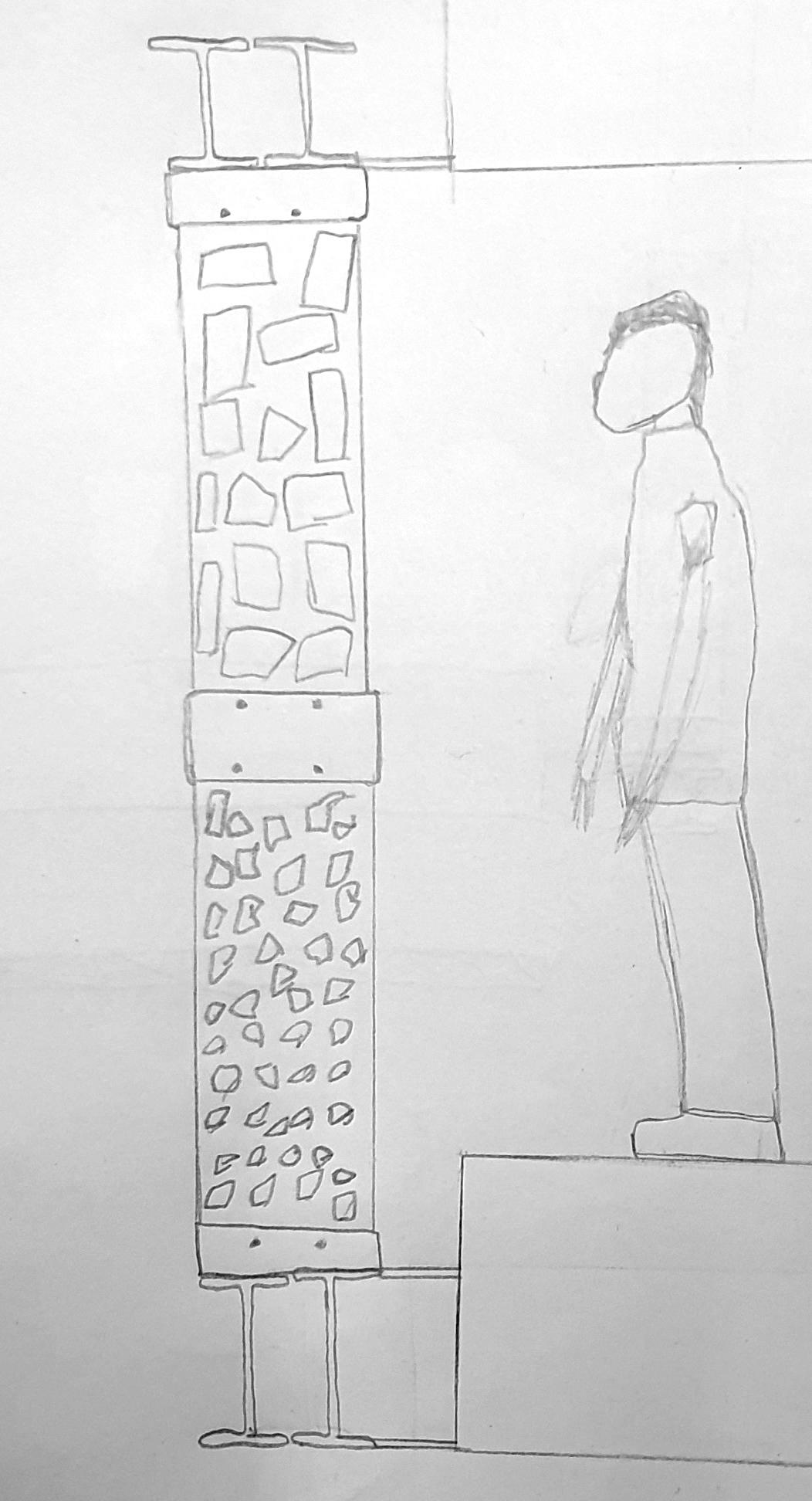
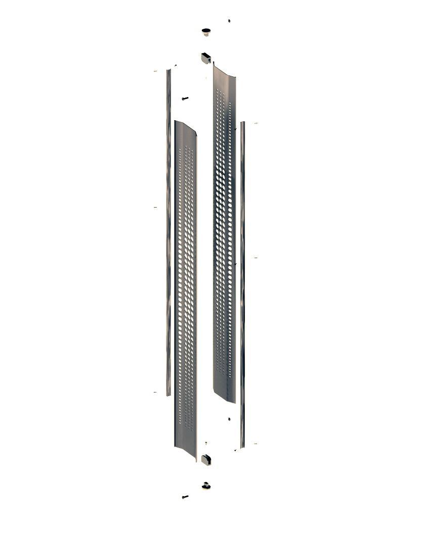
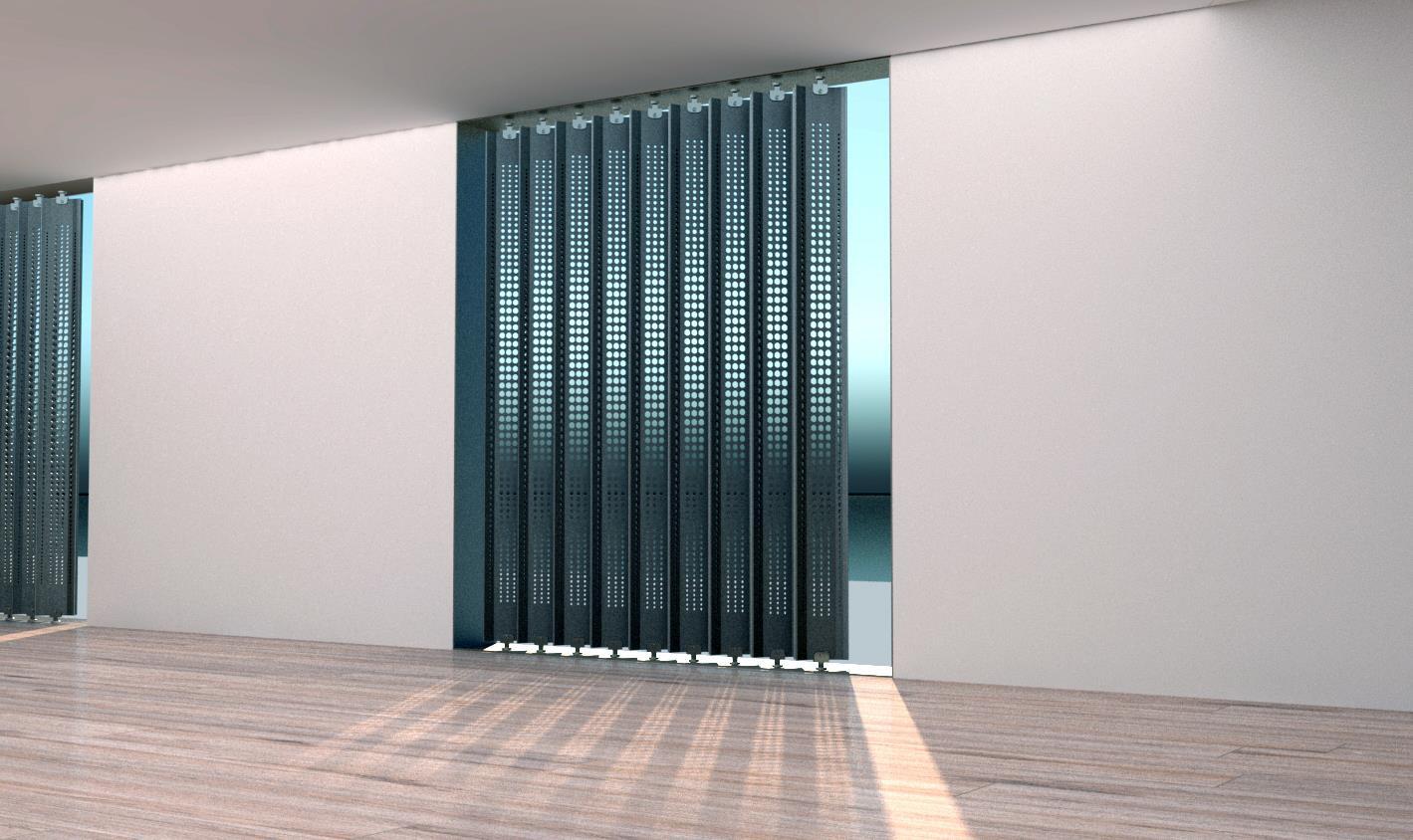
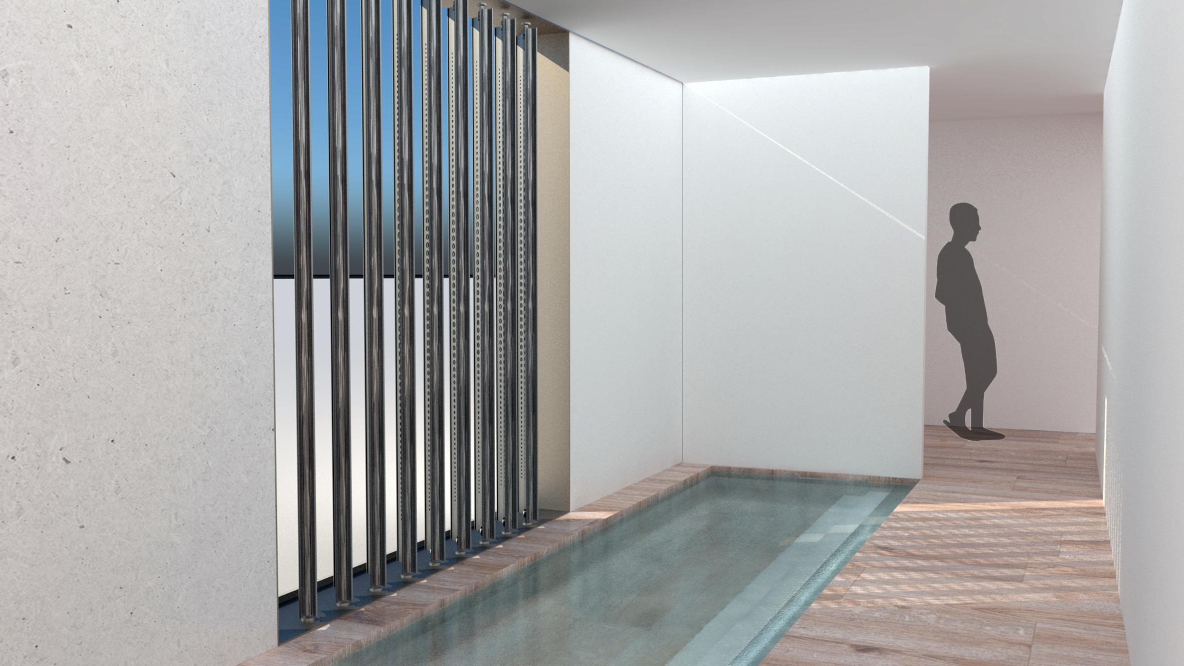
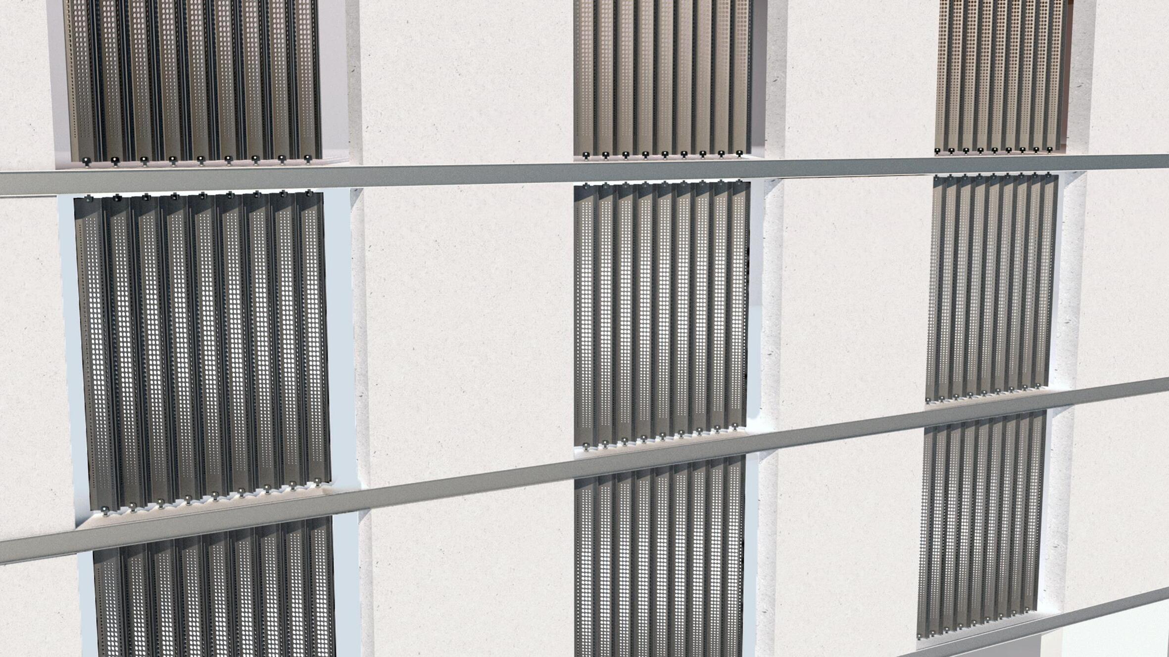
The main focus in designing the louver was to achieve the desired “rain of light” effect while ensuring privacy within the residences without compromising the views and natural lighting from the outside. This objective was successfully realized through the utilization of a twolayered configuration of perforated metal sheets, bent at an angle, and interconnected with c channels on both sides. The perforations in the metal sheets played a crucial role in preserving the views and allowing sufficient light transmission, while the bending of the sheets added an extra layer of heat reduction, minimizing the heat gain from the sun.
Louver proposal
A100
3.6 m 08 10
A101 .04m
07 041109
Architect: Consultant: Design Check Approve plan/Elevation:

.05 m
THIS DRAWING IS COPYRIGHT AND SHOULD NOT BE USED OR REPRODUCED FOR ANY OTHER PURPOSE OTHER THAN WHICH IT IS SUPPLIED WITHOUT THE WRITTEN CONSENT OF NAUMAN ABDULHAQ. Client: 2.76 m
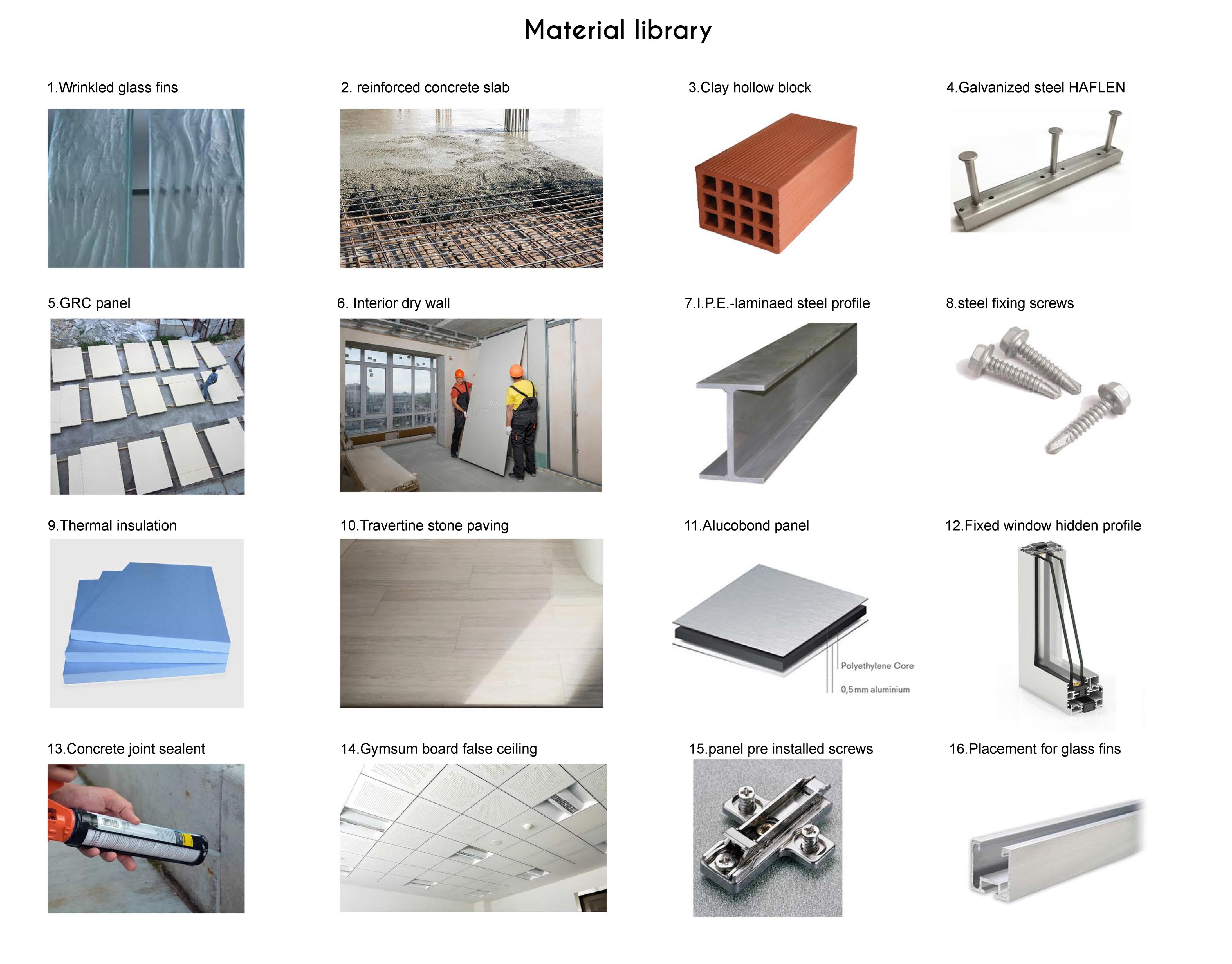
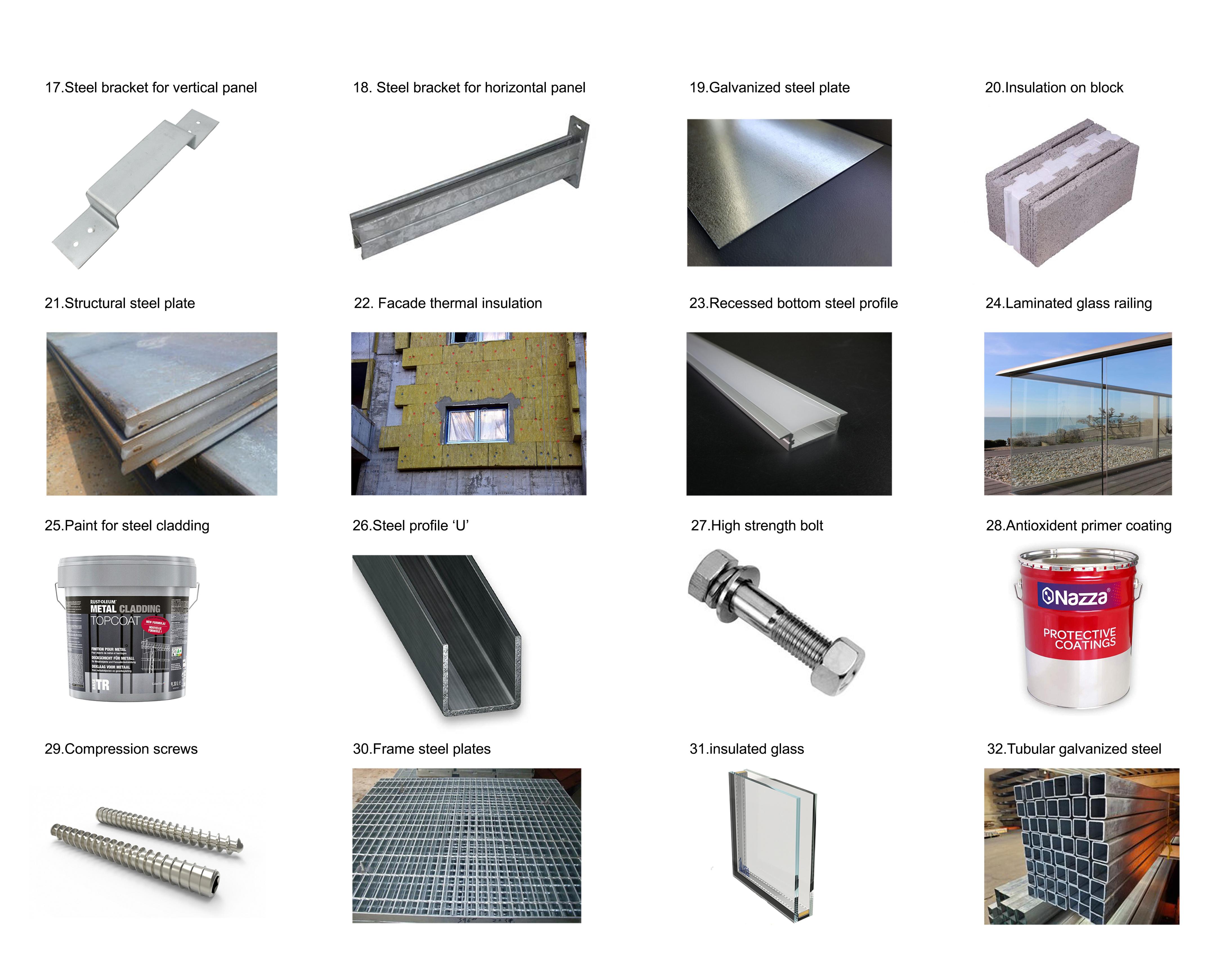
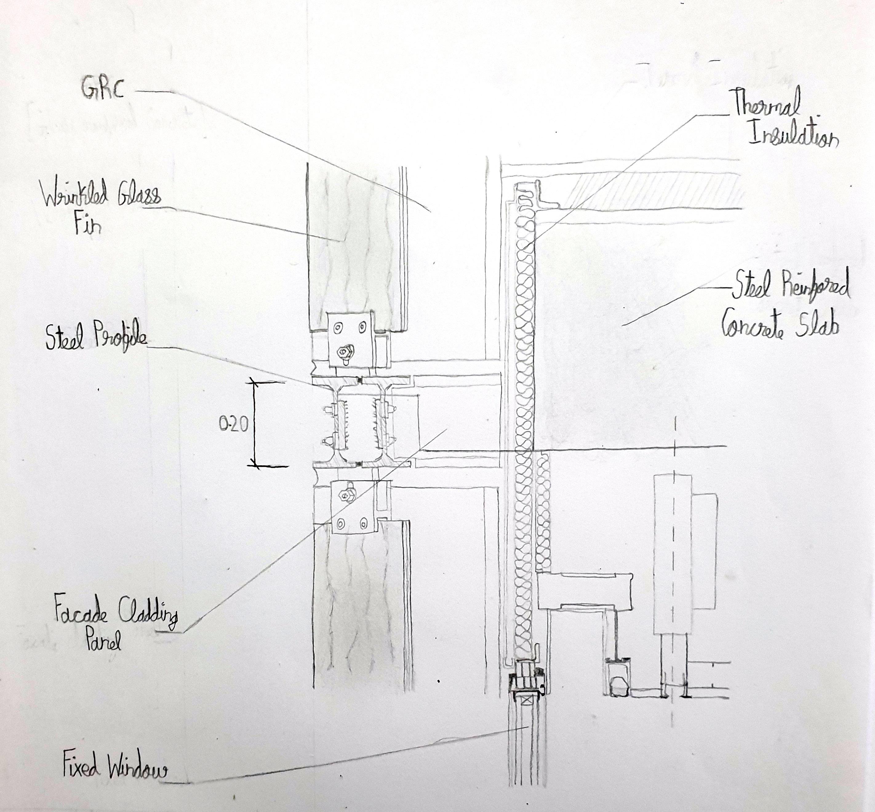
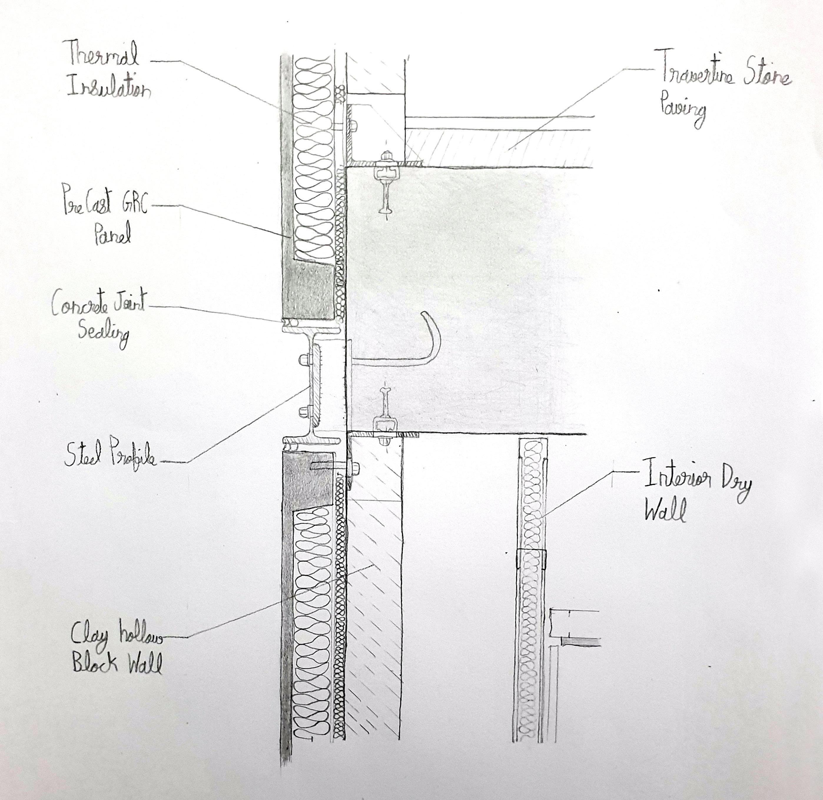
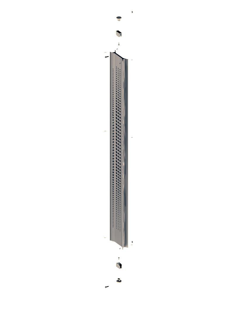
01 02 03 04 05 01: Steel reinforced concrete slab 02: Steel element for supporting fixing of galvanized steel louver 03: Perforations in louver 04: Louver made up of 2 galvanized steel sheets 05: Fixed window hidden profile 06: Precast GRC panel 07: Travertine stone paving 08: Steel fixing screws 09: I.P.E.-laminaed steel profile 10: Alucobond facade cladding panel 11: Thermal insulation
Key .20 m 3.25 m .26 m
06 11
09
title:
no.
Job no. Project Drawing
Drawing
Index Format: A3 Name Signature
Notes:
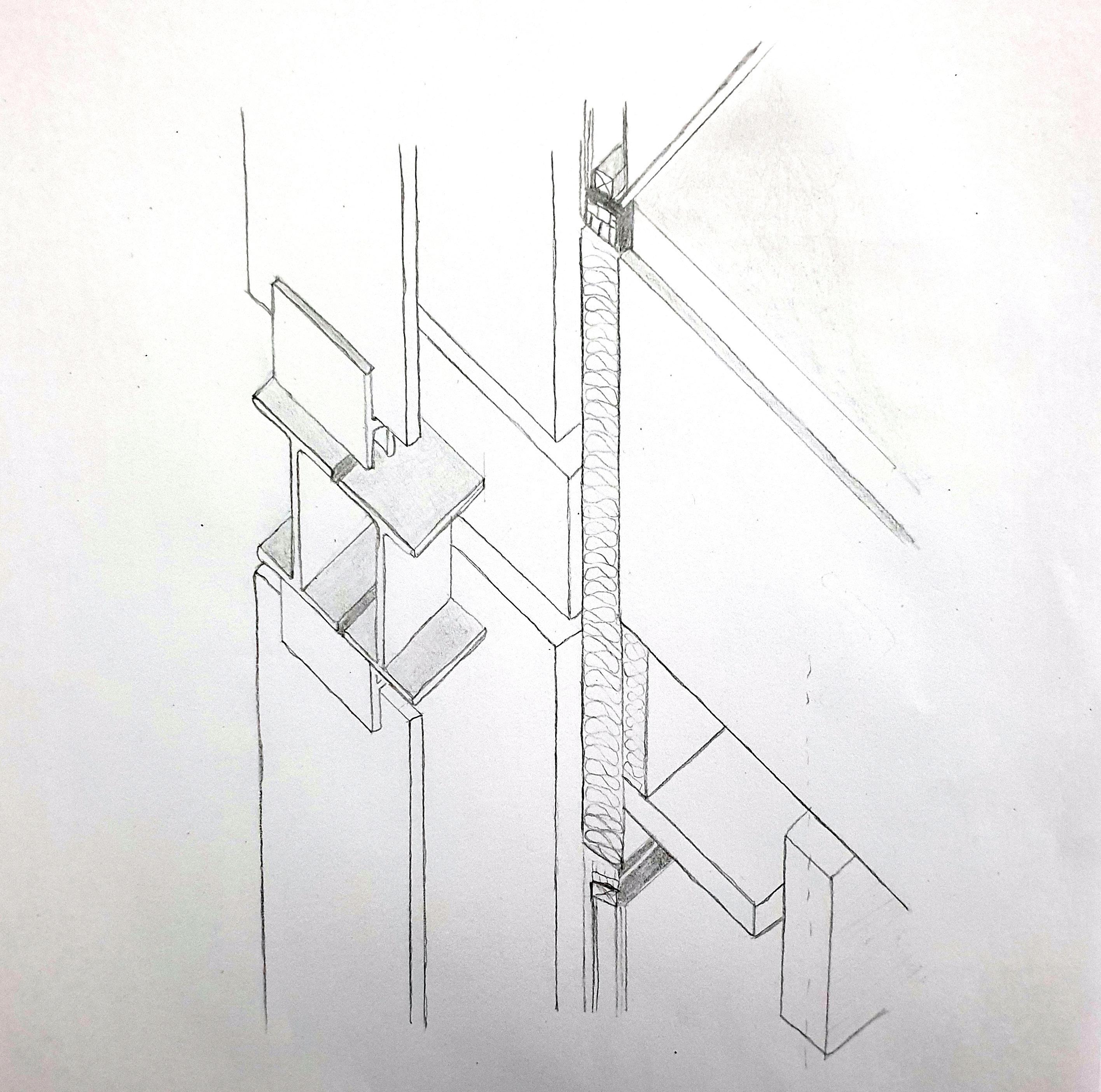
THIS DRAWING IS COPYRIGHT AND SHOULD NOT BE USED OR REPRODUCED FOR ANY OTHER PURPOSE OTHER THAN WHICH IT IS SUPPLIED WITHOUT THE WRITTEN CONSENT OF NAUMAN ABDULHAQ.
01: Alucobond facade cladding panel

02: Thermal insulation
03: Steel reinforced concrete slab
04: Perforation in the metel sheets
05: Steel screws used to connect the 2 galvanized sheets together to form the louver
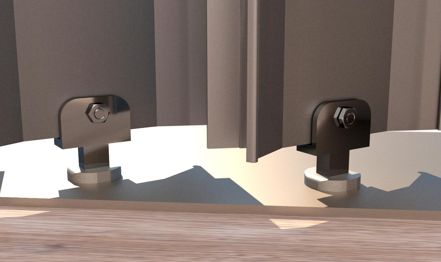
06: Steel plate like element, welded to I-beam
07: Steel bolt used to connect the louver with the steel support.
08: Steel element for supporting fixing of galvanized steel louver
09: Silicone filing for air gaps
10: C channel
11: Galvanized steel sheet
12: Fixed window hidden profiles with insulating glass
Job no.
Project Drawing title: Drawing no.
Format: A3
Name Signature Notes: Architect: Consultant: Design Check Approve
Client: 4cm
Index
Key plan/Elevation:
02 03 1.1cm 1.7cm 0708 12 10 Ø 6cm 11 23.5° 15.9cm 01 06050409
A100
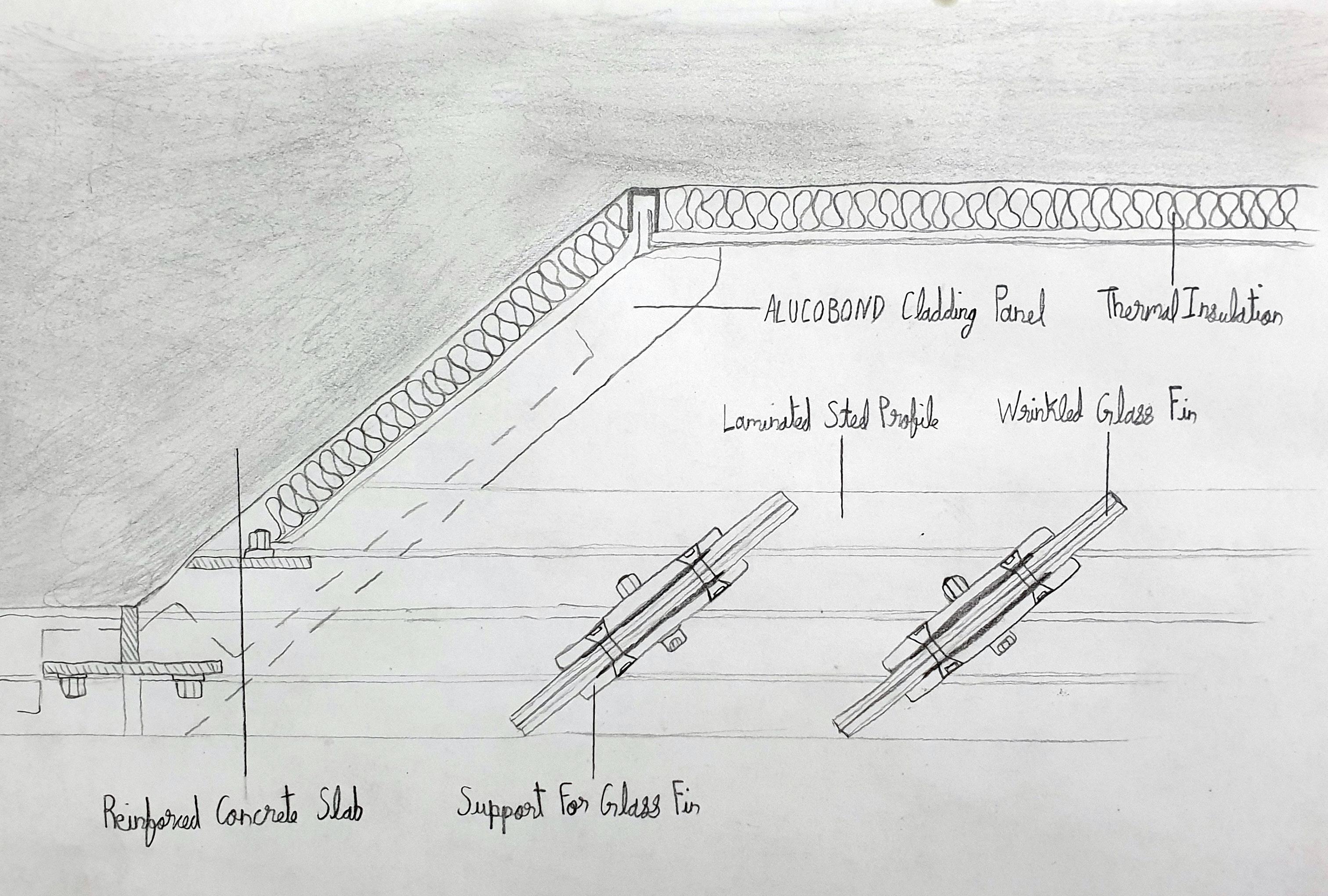
01: Thermal insulation
02: I.P.E.-laminaed steel profile
03: Alucobond facade cladding panel
04: Steel element welded to I-beam
05: Steel component used to connect the louver shoe with the I-beam
06: fixing Screws
07: Silicone filling
08: Steel bolt used to connect the louver with the steel support.
09: Steel shoe used to hold the louver
10: Galvanized steel sheet
11: Precast GRC panel
Key plan/Elevation:
Notes:
THIS DRAWING IS COPYRIGHT AND SHOULD NOT BE USED OR REPRODUCED FOR ANY OTHER PURPOSE OTHER THAN WHICH IT IS SUPPLIED WITHOUT THE WRITTEN CONSENT OF NAUMAN ABDULHAQ.
Architect: Consultant: Design Check Approve

Name Signature
Job no.
Project
Drawing title:
Drawing no.
Index
Format: A3
Client: 5.5 cm 07 06 05 04 03 02 09 01 1.25 cm 2.8 cm
11 10 08 A101
Architect: Nauman Abdulhaq

Consultant:
Key plan/Elevation:
Notes:
THIS DRAWING IS COPYRIGHT AND SHOULD NOT BE USED OR REPRODUCED FOR ANY OTHER PURPOSE OTHER THAN WHICH IT IS SUPPLIED WITHOUT THE WRITTEN CONSENT OF NAUMAN ABDULHAQ. Design Check Approve
Job no.
Project
Drawing title: 3 step Diagram
Drawing no.
Format: A3
Client: Professor Igor
Name Signature
1 3 2
Key plan/Elevation:
Notes:
THIS DRAWING IS COPYRIGHT AND SHOULD NOT BE USED OR REPRODUCED FOR ANY OTHER PURPOSE OTHER THAN WHICH IT IS SUPPLIED WITHOUT THE WRITTEN CONSENT OF NAUMAN ABDULHAQ.
Architect: Consultant: Design
Name Signature
Check Approve
Job no.
Project
Drawing title:
Drawing no.
Index
Format: A3
12
Client:
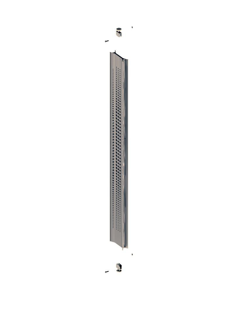
Exploded axonometric
Client: Professor Igor
Consultant:
Key plan/Elevation:
Notes:
Architect: Nauman abdulhaq THIS DRAWING IS COPYRIGHT AND SHOULD NOT BE USED OR REPRODUCED FOR ANY OTHER PURPOSE OTHER THAN WHICH IT IS SUPPLIED WITHOUT THE WRITTEN CONSENT OF NAUMAN ABDULHAQ.
Name Signature
Design
Check
Approve
Job no.
Project
Drawing title- exploded axon
Format- A3
Drawing no.-
Drawing index
43
Client:
Key plan/Elevation:
Notes:
THIS DRAWING IS COPYRIGHT AND SHOULD NOT BE USED OR REPRODUCED FOR ANY OTHER PURPOSE OTHER THAN WHICH IT IS SUPPLIED WITHOUT THE WRITTEN CONSENT OF NAUMAN ABDULHAQ.
Architect: Consultant: Design Check Approve
Name Signature
Job no.
Project Drawing title: Drawing no.
Index Format: A3
Client: Professor Igor
Architect: Nauman abdulhaq
Consultant:
Notes:
THIS DRAWING IS COPYRIGHT AND SHOULD NOT BE USED OR REPRODUCED FOR ANY OTHER PURPOSE OTHER THAN WHICH IT IS SUPPLIED WITHOUT THE WRITTEN CONSENT OF NAUMAN ABDULHAQ.
Job no.
Project
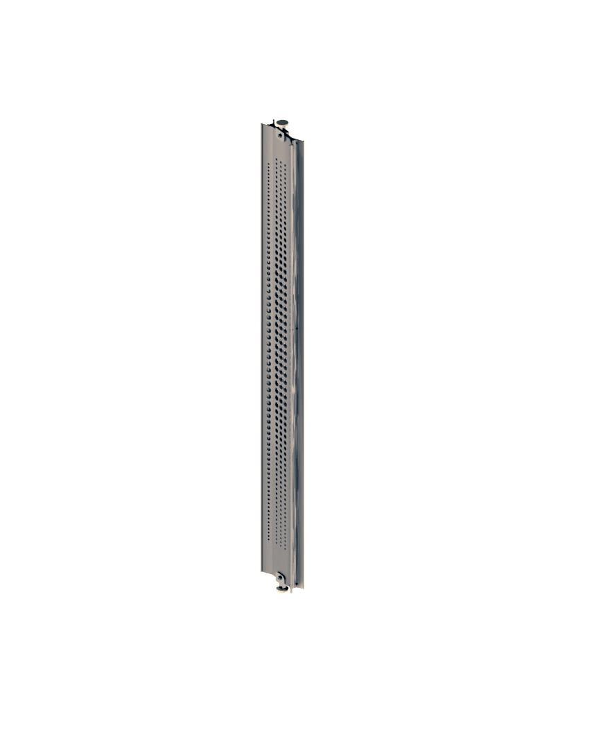
Drawing title: Connection render
Format: A3

Design Check Approve
Name Signature
Key plan/Elevation:
Client:
Key plan/Elevation:
Notes:
THIS DRAWING IS COPYRIGHT AND SHOULD NOT BE USED OR REPRODUCED FOR ANY OTHER PURPOSE OTHER THAN WHICH IT IS SUPPLIED WITHOUT THE WRITTEN CONSENT OF NAUMAN ABDULHAQ.
Architect: Consultant: Design Check Approve
Name Signature
Job no.
Project Drawing title: Drawing no.
Index Format: A3
Client:
Key plan/Elevation:
Notes:
THIS DRAWING IS COPYRIGHT AND SHOULD NOT BE USED OR REPRODUCED FOR ANY OTHER PURPOSE OTHER THAN WHICH IT IS SUPPLIED WITHOUT THE WRITTEN CONSENT OF NAUMAN ABDULHAQ.
Architect: Consultant: Design Check Approve
Name Signature
Job no.
Project
Drawing title:
Drawing no.
Index
Format: A3
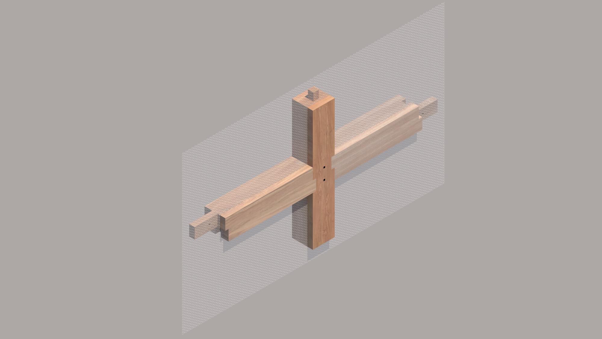
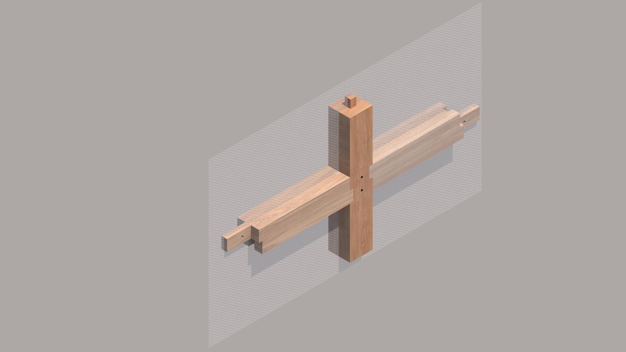
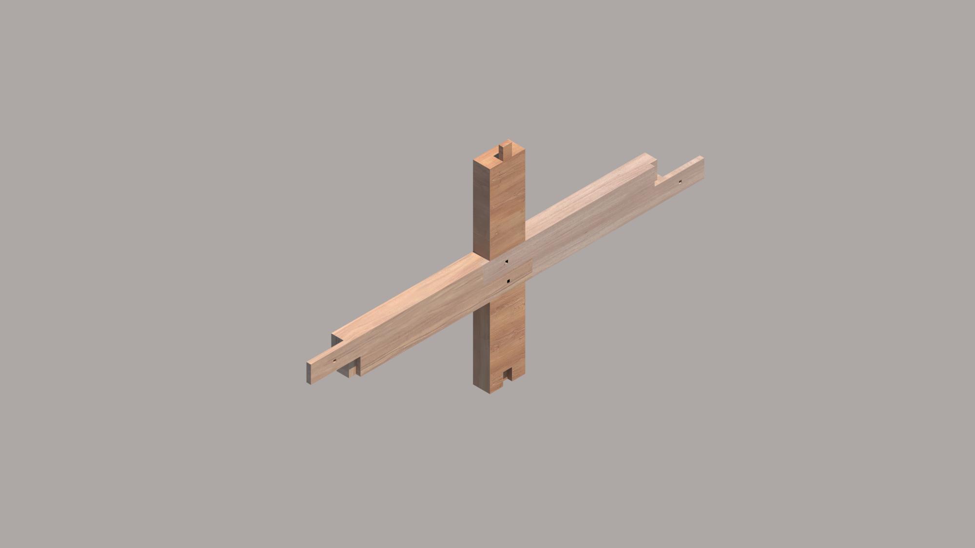
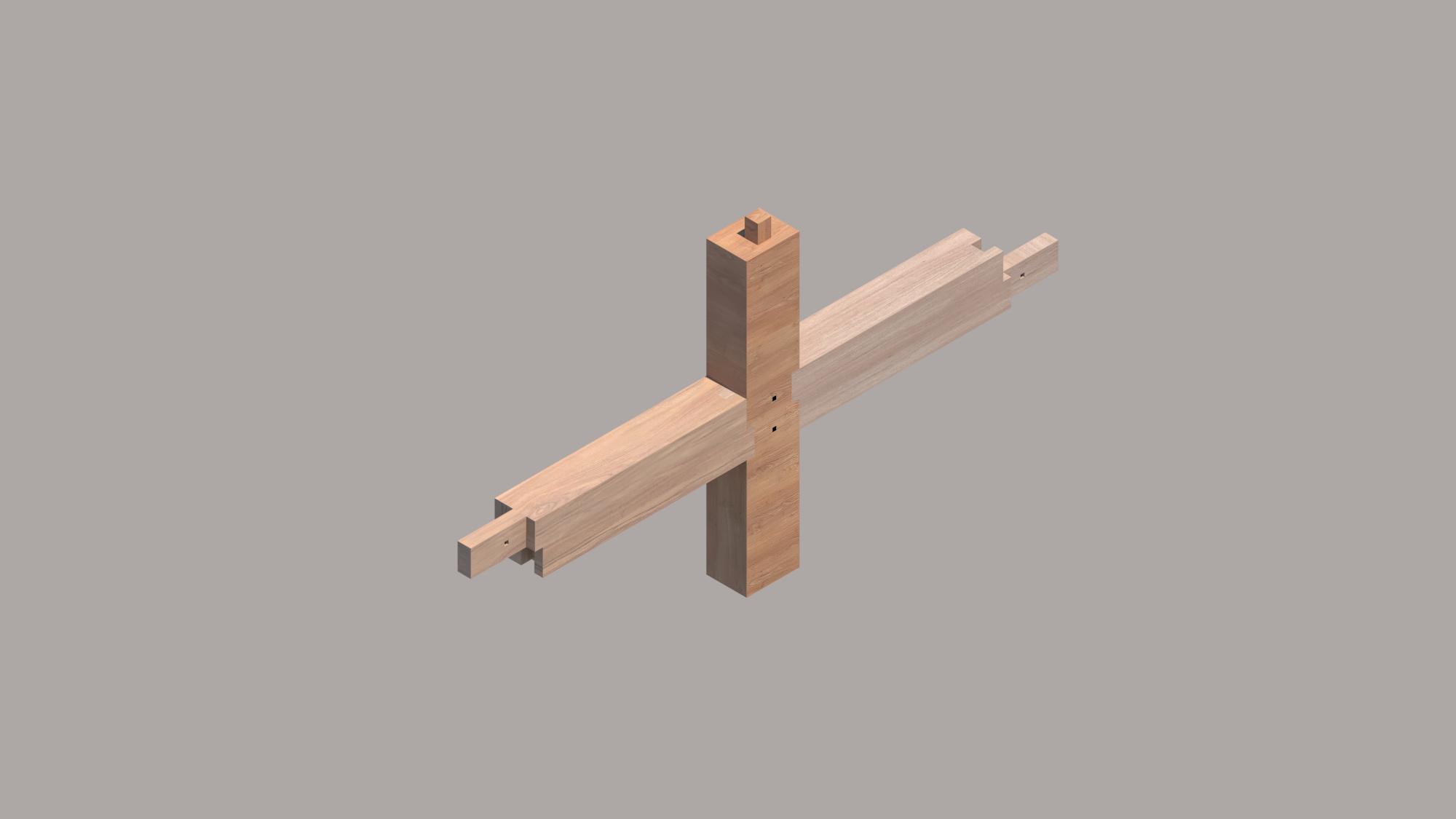
A3 Japanese joints
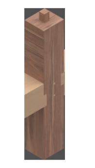
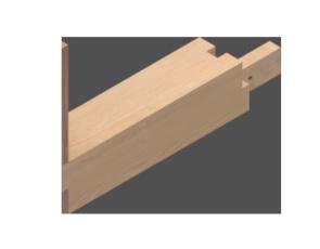
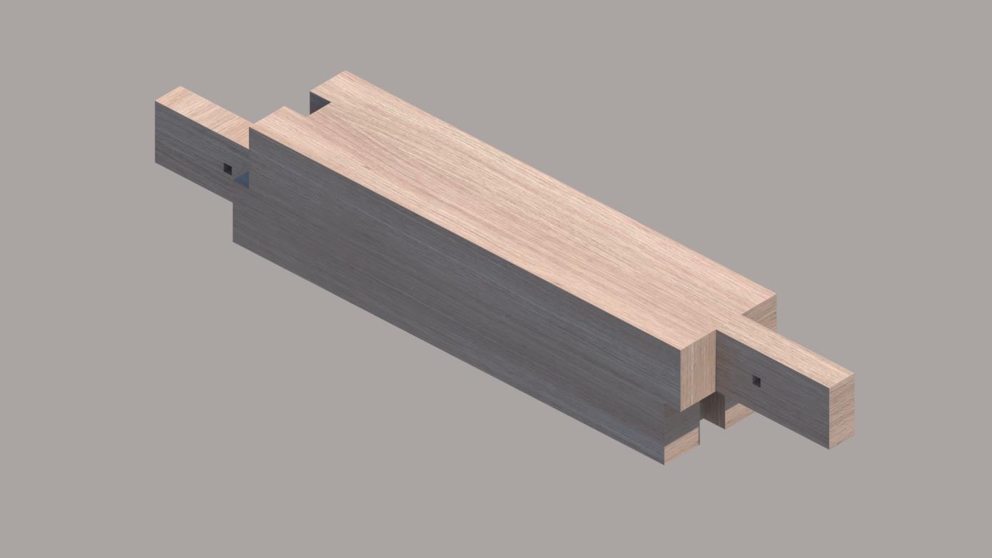
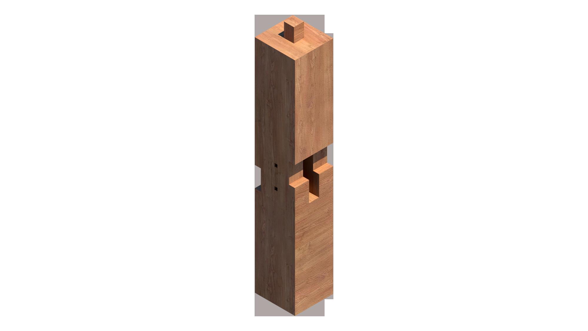
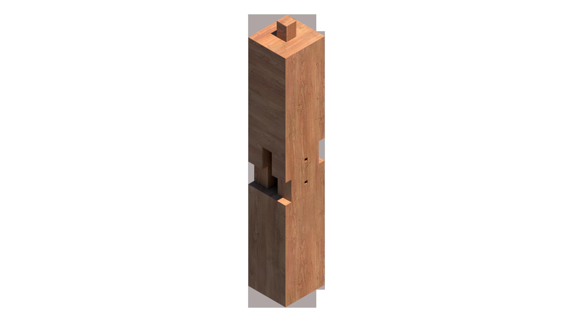
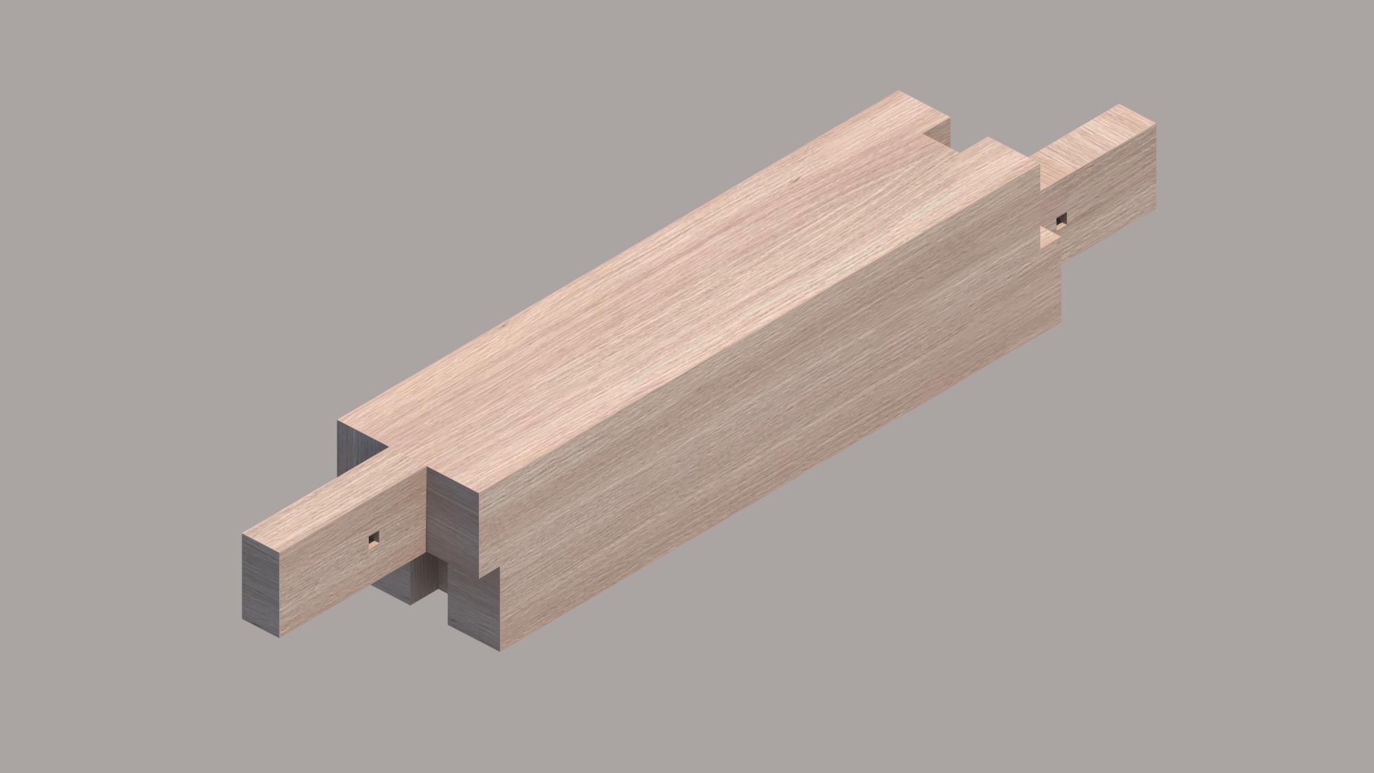
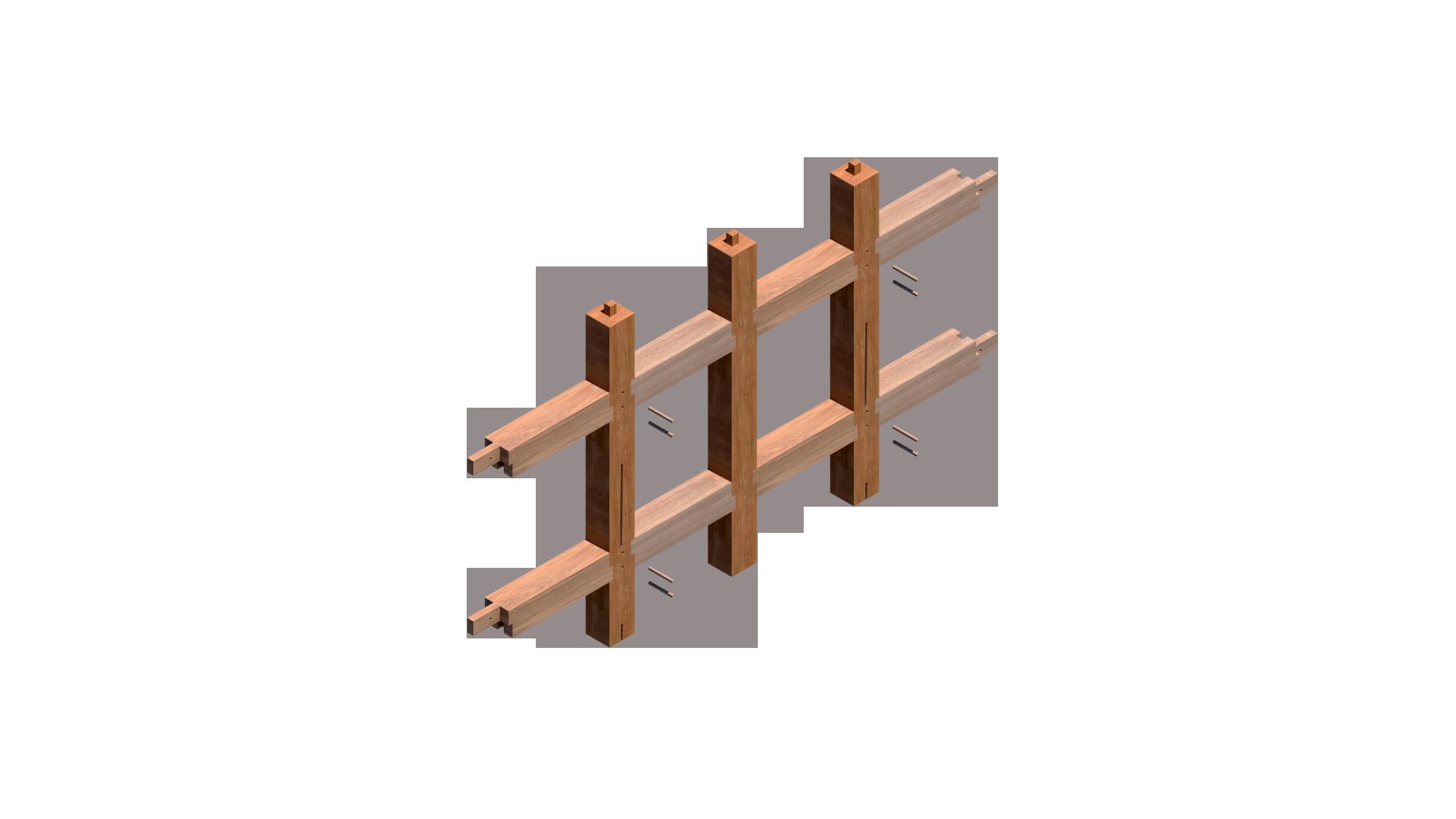
The Ashikatame beam joint is a traditional Japanese woodworking joint used in timber framing. It is a type of mortise-and-tenon joint that is commonly used to join beams at right angles, such as in the construction of post-and-beam structures or traditional Japanese timber buildings. In cases when there isn't a continuous ground sill to sustain the loads on the floor, an ashikatame beam joins posts and beams.The lengthy tenons glide past and over one another, increasing the surface area in contact and hence the resistance to twisting. With the help of two square hardwood pins, the beams are fastened to the column.
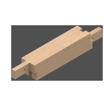
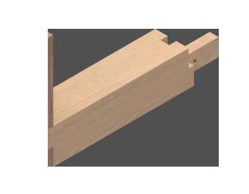
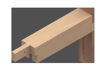
One notable feature of the Ashikatame joint is its aesthetic appeal, as it often results in a clean and elegant joint that showcases the natural beauty of the wood. It also provides good structural stability and can withstand the loads and stresses placed on beams in timber-framed structures.
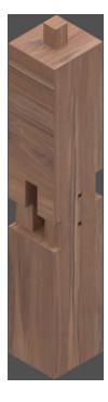

Ashikatame Beam Joint
Element
THIS DRAWING IS COPYRIGHT AND SHOULD NOT BE USED OR REPRODUCED FOR ANY OTHER PURPOSE OTHER THAN WHICH IT IS SUPPLIED WITHOUT THE WRITTEN CONSENT OF NAUMAN ABDULHAQ.
Client- Igor Peraza
Project- A3 japanese joint


Drawing title- Elevations
Drawing no.1
Drawing unit: Milimeters
Scale-1:6
Format- A3
100 7070 50 210 210 7070 127.5 210 70 67.5 210 70 800 30 42.5 42.5 190 210 30 50 210 190 15 70 200 200 210 200 100 210 100 40760 800 100 100 100 240 24015800 210 30 100 100 70 190 1250 800 190 1250 800 50 100 30 50 ElevationC Elevation D Elevation C Elevation A ElevationA ElevationB ElevationD ElevationE ElevationF Elevation F Elevation EElevation B
A of the joint Notes:
Element B
Notes:
THIS DRAWING IS COPYRIGHT AND SHOULD NOT BE USED OR REPRODUCED FOR ANY OTHER PURPOSE OTHER THAN WHICH IT IS SUPPLIED WITHOUT THE WRITTEN CONSENT OF NAUMAN ABDULHAQ.
Client- Igor Peraza
Project- A3 japanese joint

Drawing title- Elevations

Drawing no.2
Drawing unit: Milimeters
Scale-1:6
Format- A3
of the joint
190 1100 70 50 100 15 5070 450 70 450 50 50 200 100 15 50 200 200 100 15 15 50 550 70 70 70 50 70 100 100 450 550 1100 100 350 190 190 75 190 50 70 70 15 200 450 1170 190 75 50 7575 15 15 1170 190 100 50 200 200 100 70 15 550 Elevation E ElevationA ElevationC ElevationF ElevationB ElevationD Elevation A Elevation B Elevation EElevation FElevation D Elevation C
Element C
Notes:
THIS DRAWING IS COPYRIGHT AND SHOULD NOT BE USED OR REPRODUCED FOR ANY OTHER PURPOSE OTHER THAN WHICH IT IS SUPPLIED WITHOUT THE WRITTEN CONSENT OF NAUMAN ABDULHAQ.
Client- Igor Peraza
Project- A3 japanese joint
Drawing title- Elevations
Drawing no.3
Drawing unit: Milimeters
Scale-1:6
Format- A3
of the joint
190 50 210 70 210 30 70 190 50 70 210 800 70 50 7070 7070 50 200 100 210 200 40760 100 1250 1250 100 800 30 190 100 210 127.5 190 67.5240 100 800 15800 42.5 210 42.5 15 800 30 200 100 240 30 100 210210 100100 210 ElevationB Elevation B Elevation F Elevation D Elevation A ElevationA ElevationD Elevation C ElevationE ElevationC ElevationF Elevation E


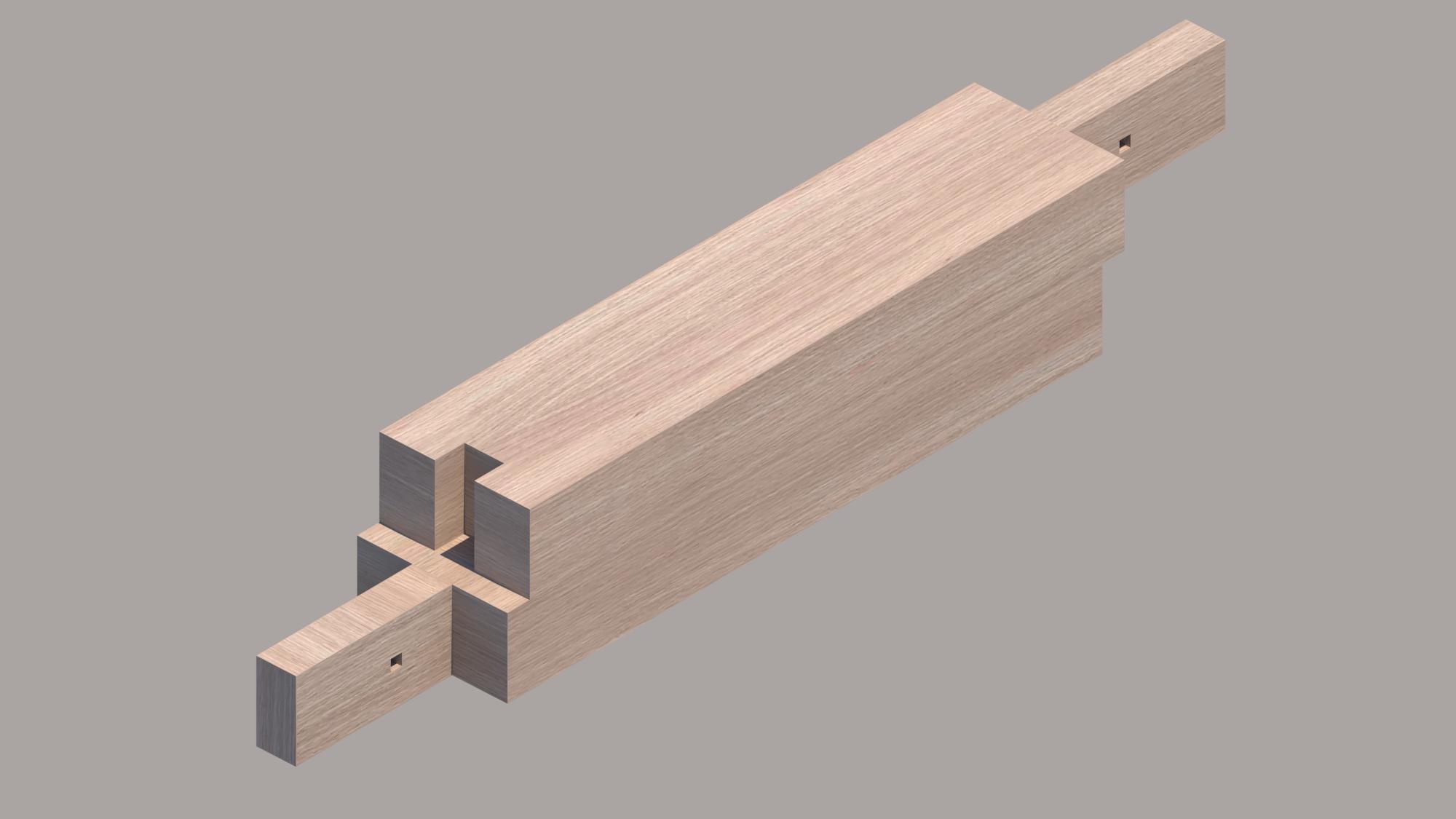
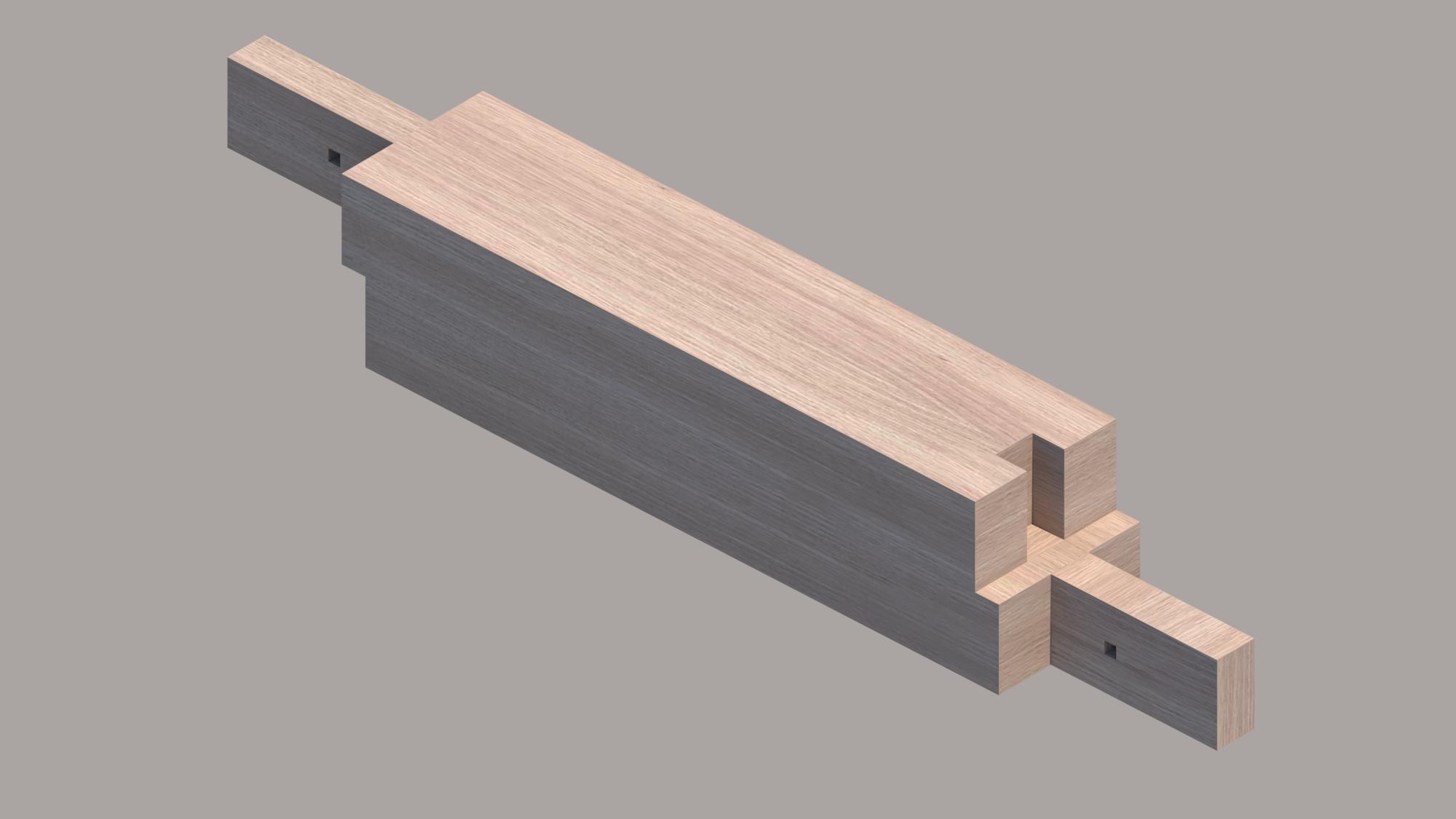
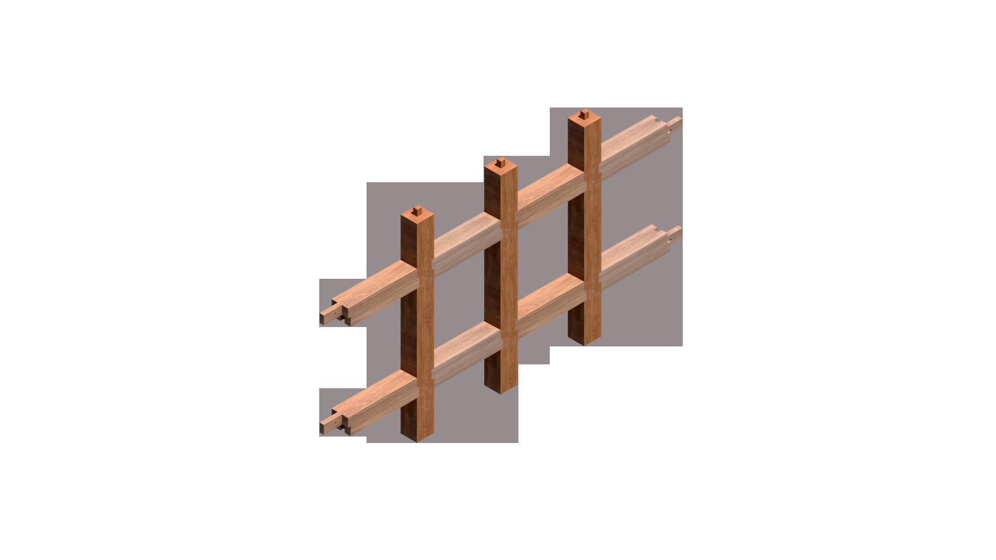
WHICH IT IS SUPPLIED WITHOUT Isometric view of the joint
North eastNorth west
South westSouth eastNorth eastNorth west
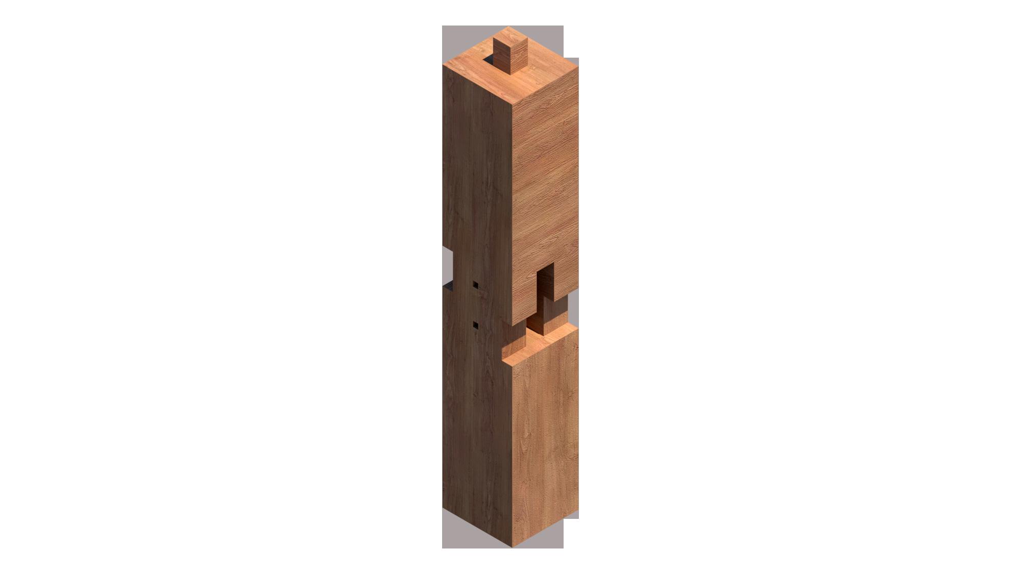
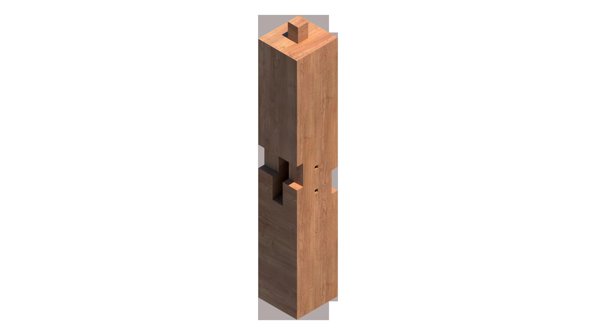
Vertical Element
Horizontal Element
South westSouth east
elements
joint,
21 4 Step Diagram 34
Project- A3 japanese joint
Drawing title- Joint diagram
Drawing no.5
of
Notes: THIS DRAWING IS COPYRIGHT AND SHOULD NOT BE USED OR REPRODUCED FOR ANY OTHER PURPOSE OTHER THAN WHICH IT IS SUPPLIED WITHOUT THE WRITTEN CONSENT OF NAUMAN ABDULHAQ. coming
together
Client- Igor Peraza
Format- A3
Notes: THIS DRAWING IS COPYRIGHT AND SHOULD NOT BE USED OR REPRODUCED FOR ANY OTHER PURPOSE OTHER THAN WHICH IT IS SUPPLIED WITHOUT THE WRITTEN CONSENT OF NAUMAN ABDULHAQ.
Section
joint
of complete
Client- Igor Peraza
15 970 100 280 40 730 755075 100 970 450 100 70 15 70 100100450 450 40 280 40 210 40 730 70 75 380 800200 40 770 450 240 730 50 100 75 280970 100 15 15 70380450 520 75 100 405075 SectionAA SectionBB Section AA Section BB
Project- A3 japanese joint Drawing title- Section Drawing no.6 Format- A3
THIS DRAWING IS COPYRIGHT
OTHER PURPOSE OTHER THAN WHICH IT IS SUPPLIED WITHOUT
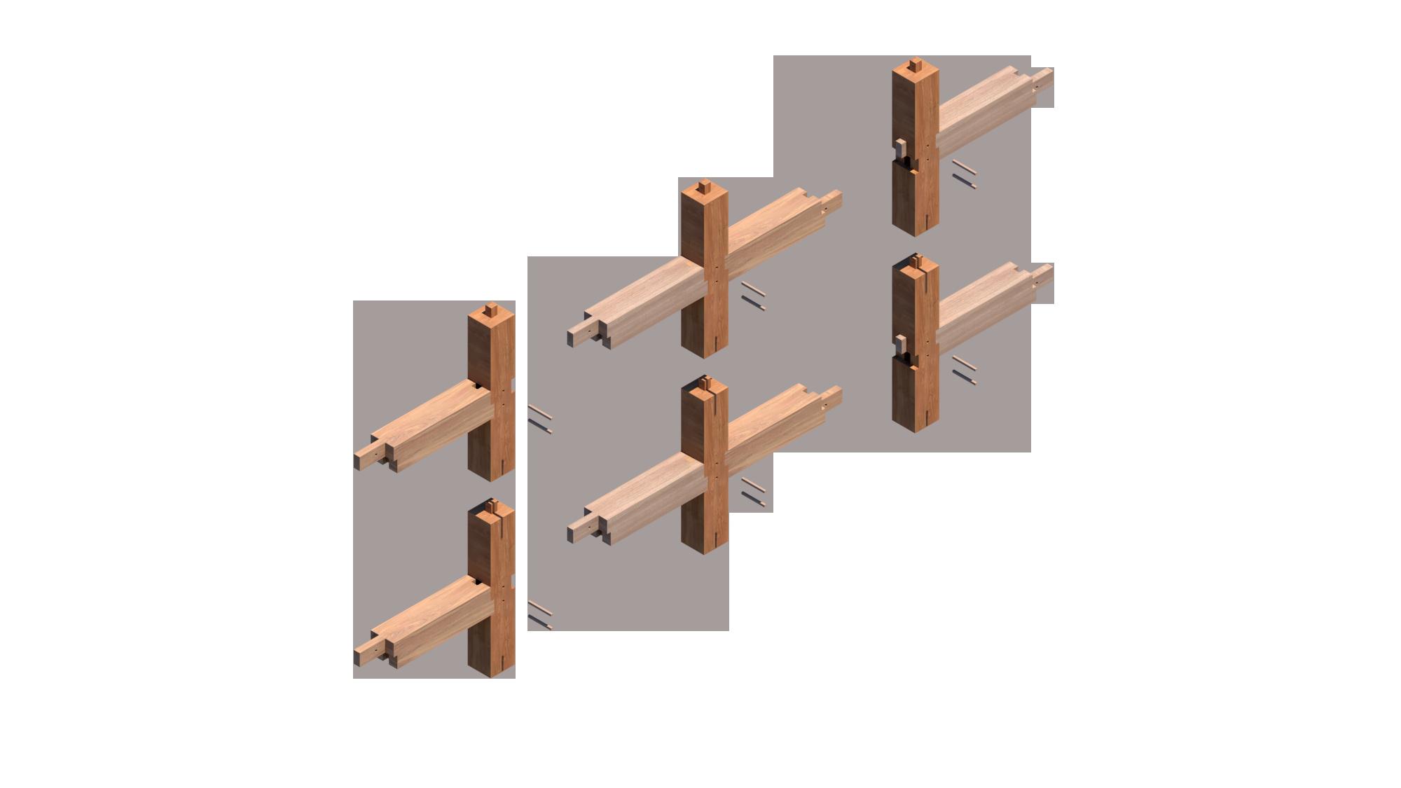
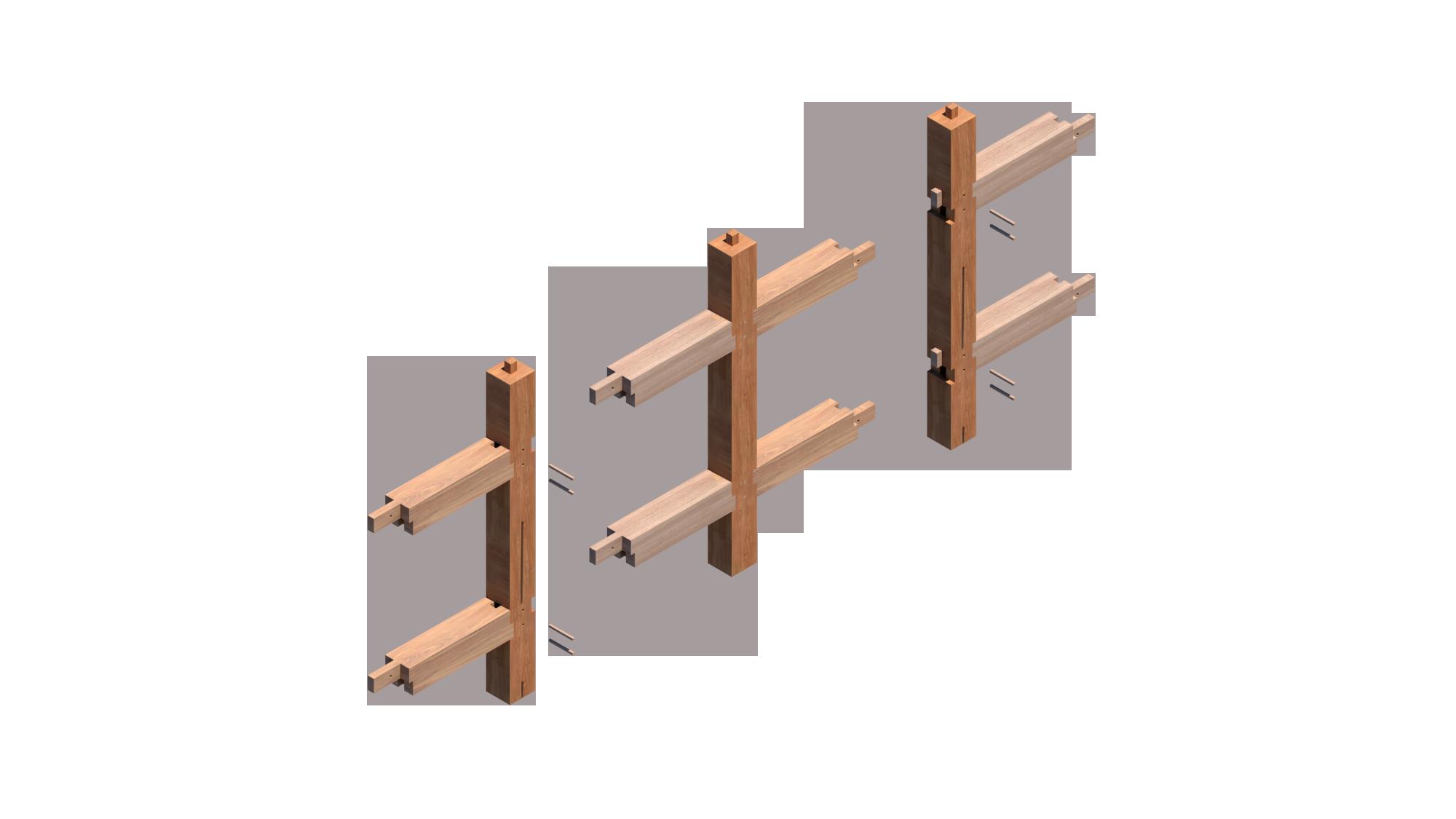
coming
Multiple joints
Drawing title- Joint diagram 4
Module of joints to create a pavilion 2 3
1
History Of Japanese Wood Joinery


History And Culture
Over a thousand years ago, Japanese carpentry was shaped and evolved by adopting architectural influences from China starting in the 12th century. This traditional practice of woodworking draws inspiration from ancient Chinese wooden architecture and employs intricate joinery techniques. Notably, it involves constructing wooden furniture without relying on nails, screws, glue, or modern electric tools.Although construction methods that exclude nails and fasteners are not exclusive to Japan, the distinctive feature of Japanese joinery lies in the specific types of joints employed, the exceptional durability of the resulting structures, and the complete absence of iron.Apart from enabling convenient repairs, the absence of nails in construction not only enhances the resilience of buildings against Japan's frequent earthquakes but also allows the joints to flex and withstand seismic forces while retaining their structural integrity. While this is not the sole factor contributing to the longevity of these buildings over centuries, it undeniably plays a crucial role. Such techniques persist in modern construction practices as well.
Similar to various traditional Japanese arts like sushi-making or flower arranging, the realm of Japanese carpentry is teeming with individuals who have devoted their lives, spanning generations, to pursue an elusive state of perfection.In Japan, elaborate joinery techniques are utilized not solely for their practical benefits but also to emphasize the artistry involved and elevate the overall aesthetic appeal.
Tools Used
Artisans practicing traditional Japanese techniques rely on an extensive assortment of tools, with each tool having numerous sizes and variations, all meticulously sharpened to razor-like precision. Although power tools are sporadically employed for larger undertakings, it is the delicate hand-tools that take center stage in crafting the intricate joints essential to their projects.
Japanese chisels, known as "nomi," (image referenced below) feature slender blades designed for material removal, creating notches, or drilling holes in wood. Available in a vast range of shapes and sizes, these chisels possess exceptional sharpness due to their hardened steel construction, enabling effortless woodcutting. While a traditional Japanese craftsperson's workbench typically hosts numerous tools, these instruments hold paramount importance in Japanese joinery as they are the primary and frequently utilized tools.

Notes: THIS DRAWING IS COPYRIGHT AND SHOULD NOT BE USED OR REPRODUCED FOR ANY OTHER PURPOSE OTHER THAN WHICH IT IS SUPPLIED WITHOUT THE WRITTEN CONSENT OF NAUMAN ABDULHAQ.
Client- Igor Peraza
Project- A3 japanese joint
Drawing title- Introduction
Format- A3
Historical Context
joint representation through a pavilion

Idea of the Pavilion
The pavilion is set to be a type of a japanese restaurant which embraces the different types of seating with the help of the joint The pavilion is set in the middle of a plaza, makes it a prominent place for encouraging daily interaction between the people in the community
Exterior render of pavilion

Notes: THIS DRAWING IS COPYRIGHT AND SHOULD NOT BE USED OR REPRODUCED FOR ANY OTHER PURPOSE OTHER THAN WHICH IT IS SUPPLIED WITHOUT THE WRITTEN CONSENT OF NAUMAN ABDULHAQ.
Client- Igor Peraza
Project- A3 japanese joint
Drawing title- perspectives
Format- A3
Exterior render of pavilion
Exterior render of pavilion

Notes: THIS DRAWING IS COPYRIGHT AND SHOULD NOT BE USED OR REPRODUCED FOR ANY OTHER PURPOSE OTHER THAN WHICH IT IS SUPPLIED WITHOUT THE WRITTEN CONSENT OF NAUMAN ABDULHAQ.
Notes: THIS DRAWING IS COPYRIGHT AND SHOULD NOT BE USED OR REPRODUCED FOR ANY OTHER PURPOSE OTHER THAN WHICH IT IS SUPPLIED WITHOUT THE WRITTEN CONSENT OF NAUMAN ABDULHAQ.
Client- Igor Peraza
Project- A3 japanese joint
Drawing title- perspectives
Format- A3
Client- Igor Peraza
Project- A3 japanese joint

Drawing title- perspectives
Format- A3
Exterior render of pavilion


Notes: THIS DRAWING IS COPYRIGHT AND SHOULD NOT BE USED OR REPRODUCED FOR ANY OTHER PURPOSE OTHER THAN WHICH IT IS SUPPLIED WITHOUT THE WRITTEN CONSENT OF NAUMAN ABDULHAQ.
Notes: THIS DRAWING IS COPYRIGHT AND SHOULD NOT BE USED OR REPRODUCED FOR ANY OTHER PURPOSE OTHER THAN WHICH IT IS SUPPLIED WITHOUT THE WRITTEN CONSENT OF NAUMAN ABDULHAQ.
Client- Igor Peraza
Project- A3 japanese joint
Drawing title- perspectives
Format- A3
Client- Igor Peraza
Project- A3 japanese joint
Drawing title- perspectives
Format- A3
Interior render of
pavilion
Notes: THIS DRAWING IS COPYRIGHT AND SHOULD NOT BE USED OR REPRODUCED FOR ANY OTHER PURPOSE OTHER THAN WHICH IT IS SUPPLIED WITHOUT THE WRITTEN CONSENT OF NAUMAN ABDULHAQ.
Notes: THIS DRAWING IS COPYRIGHT AND SHOULD NOT BE USED OR REPRODUCED FOR ANY OTHER PURPOSE OTHER THAN WHICH IT IS SUPPLIED WITHOUT THE WRITTEN CONSENT OF NAUMAN ABDULHAQ.
Client- Igor Peraza
Project- A3 japanese joint
Drawing title- perspectives
Format- A3
Client- Igor Peraza
Project- A3 japanese joint


Drawing title- perspectives
Format- A3
Interior render of pavilion
Interior render of pavilion
A4 Final Detail Drawings
Client: Professor Igor
Arc 382 S23 Final detail drawing 23.5°
04030106 1.6 cm
07 15.9cm 6.6cm
10 3cm
Nauman Abdulhaq 90029 65°
11 4cm 1.1cm
1.75cm 3.73cm2.42cm
09 0cm 1cm 2cm 5cm 10cm
080205 METAL LOUVER DETAIL DRAWING 01: Steel plate welded to beam 02: Washer 03: Steel nut 04: Steel bolt 05: Locking washer 06: Steel shoe 07: Silicone filing 08: Perforation in metel sheets 09: Stainless Steel screws 10: C channel 11: Galvanized steel sheet (0.4 Cm) Scale- 1:1.4 Plan
Architect: Nauman abdulhaq THIS DRAWING IS COPYRIGHT AND SHOULD NOT BE USED OR REPRODUCED FOR ANY OTHER PURPOSE OTHER THAN WHICH IT IS SUPPLIED WITHOUT THE WRITTEN CONSENT OF NAUMAN ABDULHAQ.
Ø 6cm
Name 90°
Notes:
Design
Check
Approve
Job no.
Project
Consultant: 6.95 cm
Drawing title- Louver section


Format- A3
Drawing unit- Centimenters
Scale- 1:2.5
Key plan/Elevation: Signature 5 10