Editors
Brian Baker, CLMC, Current Electric Co.
James Bernardo, CLMC, CLEP, LC, Candela Systems, Inc.
Randy Breske, CLMC, CSLC, CLEP, Current Electric Co.
Craig DiLouie, LC
Erik Ennen, CLMC, CSLC, CLEP, Center for Energy & Environment
Jimmy Hammonds, Jr., ME, CSLT, Candela Systems Corp.
Jeffrey Kinney, CLEP, CLMC, CSLC, Stones River Electric, Inc.
Dan Lareau, CLMC, Lighting Services, Inc.
Bill Sgro, CLMC, CSLC, CLEP, CEM, Eco Engineering, Inc.
Doug Stoneman, CLMC, CSLC, Philips Lighting, Inc.
Chuck Smith, Current Electric Co.
Brian Baker, CLMC, Current Electric Co.
James Bernardo, CLMC, CLEP, LC, Candela Systems Corp.
Randy Breske, CLMC, CSLC, CLEP, Current Electric Co.
Erik Ennen, CLMC, CSLC, CLEP, Center for Energy & Environment
Jeffrey Kinney, CLMC, CSLC, Stones River Electric, Inc.
Dan Lareau, CLMC, Lighting Services, Inc.
Bill Sgro, CLMC, CSLC, CLEP, CEM, Eco Engineering, Inc.
Doug Stoneman, CLMC, CSLC, Philips Lighting, Inc.
With Contributions by NALMCO Certification Committee Cover Illustration
Echo Factory, Inc.
2
©
2014 NALMCO.
COPYRIGHT INFORMATION, NALMCO CONTACT INFO,
ETC.
3 TABLE OF CONTENTS
...............................................................................................................................................................4
INTRODUCTION
.......................................................................................................................5
CHAPTER 1: LIGHTING FUNDAMENTALS
........................................................................................................17
LUMINAIRES ...............................................................................................................................................25
.............................................................................................................................32
ENERGY MANAGEMENT / LIGHTING CONTROLS..................................................................................... 40
SAFETY AND CODE ....................................................................................................................................55
TROUBLESHOOTING ..................................................................................................................................64 GLOSSARY.....................................................................................................................................................................79 QUIZ ANSWER KEYS .......................................................................................................................................................82
CHAPTER 2: PLANNED LIGHTING MAINTENANCE
CHAPTER 3:
CHAPTER 4: EMERGENCY LIGHTING
CHAPTER 5:
CHAPTER 6:
CHAPTER 7:
TABLE OF CONTENTS
INTRODUCTION
Lighting management means ensuring that the lighting system consistently works at its best for the lowest operating and maintenance cost. Lighting management companies offer professionals who clean lighting systems so they work like new, troubleshoot and fix problems, and substitute new parts to reduce energy costs and improve performance. As lighting systems become more complex and the need for competent lighting expertise increases, lighting management services become more critical.
As a Certified Senior Lighting Technician (CSLT), you will provide these services. As a result, you will need to learn about planned maintenance, how to run a field crew, lighting design fundamentals, luminaires, energy management, lighting controls, emergency lighting and troubleshooting common system problems. This manual provides a significant amount of information for you to learn. Quizzes are provided at the end of each chapter so that you can check your understanding.
It’s assumed that you will be reading Illuminations after reading Lighten Up! That manual provides a lot of preparatory material you will need to know before reading Illuminations.
Let’s get started!
4 INTRODUCTION
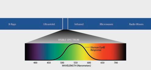
FIGURE 1-1
The electromagnetic spectrum. Visible light is electromagnetic energy that can excite the eye’s retina, producing sight. Image courtesy of OSRAM SYLVANIA.
CHAPTER 1: LIGHTING FUNDAMENTALS
LIGHT IS FOR PEOPLE
A lighting industry proverb goes, “Lighting is for people, not for buildings.” This serves as a good reminder that while saving energy is important, lighting’s primary purpose is to interact with people in desired ways—whether it be to ensure they can perform work tasks accurately and efficiently, to increase their security, to allow them to exit the building in an emergency, to draw their attention to key merchandise, etc.
If the lighting system is not doing its primary function, it’s not doing its job, and a lot of money and effort went into building and running something that isn’t working.
This is why lighting management is often defined as providing the best lighting for the lowest operating and maintenance cost. The lighting manager’s first job is to make sure that the lighting system achieves its primary mission—which is to serve people.
For this reason, it’s important that lighting managers understand the why behind each lighting system he services, not just the how. This requires a rudimentary understanding of lighting design. In this chapter, we will briefly review primary lighting design concepts, covering the tools used in both the art and science of design.
WHAT IS LIGHT?
Light is a form of radiant energy that travels in waves made up of vibrating electric and magnetic fields. These waves have both a frequency and a length, the values of which distinguish light from other forms of energy on the electromagnetic spectrum.
Light is energy. Visible light, as can be seen on the electromagnetic spectrum, represents a narrow band between ultraviolet light (UV) and infrared energy (heat). This narrow band in turn is composed of different colors/wavelengths, from violet at 380 nanometers to red at 620-760 nanometers. An even balance of these light waves comprises white visible light.
Light is color. To see this principle firsthand, look at a rainbow, which results from sunlight being refracted by droplets of moisture in the air, or simply shine a beam of white light through a glass prism to make a rainbow of colors appear on the other side.
The light waves in the visible light spectrum are capable of exciting the eye’s retina, which results in a visual sensation called sight. Therefore, seeing requires a functioning eye and visible light.
Light makes sight. Visible light itself actually cannot be seen, however. If we turned on a flashlight in a dark room, the beam of light we are seeing is not the light energy itself. What we are actually seeing in this case is light being reflected from a multitude of dust particles in the air. Therefore, seeing also requires an object for the light to strike, so that we can see it. We see objects only when light is reflected or emitted from them.
Light is invisible. We see its effect only when we see objects struck by light.
LIGHTING AND HUMAN PERFORMANCE
Between 80-85% of our impressions of the world are visual. Light makes sight: As stated above, vision requires a functioning eye and light. Perception, however, depends on how a space is lighted. And perception, as they say, is reality. With Americans spending an average of 80% of their time indoors, most lighting is therefore electric—created, designed and controlled by humans.
Man-made lighting systems define and shape the world we live in.
The National Lighting Bureau states: “Lighting affects performance in two ways: directly and indirectly. The direct effects occur because lighting alters how well we can see, either by changing the stimuli to the visual system or by changing the operating state of the visual system. The indirect effects occur because lighting can gather attention; alter arousal, mood and behavior; and modify the body’s hormone balance.”
Therefore, the amount of light available to perform a task is one critical factor, and how the space is lighted is the other. These are quantitative and qualitative aspects. The quantitative aspect determines that we have enough light to see and perform a given task efficiently and safely. The qualitative aspect impacts our mood, our impressions of the space, and draws our attention.
If you want to see the quantitative aspect in action, try to read this manual outside under moonlight. Then try to read it under sunlight. Of course, it’s easier to read it under the light of the sun. The human eye is a sophisticated piece of machinery; it is able to adjust to a
5
CHAPTER 1: LIGHTING FUNDAMENTALS
CHAPTER 1: LIGHTING FUNDAMENTALS
wide range of light levels, including about 10,000 footcandles on a sunny day to about 0.01 footcandles under full moonlight. But the eye responds best to a good minimum light level.
If you want to see the qualitative aspect in action, go to a fast food restaurant, then go to an expensive restaurant. Totally different lighting designs for two different goals. In the fast food restaurant, the light is bright, utilitarian and says: “Eat fast and leave.” In the expensive restaurant, the lighting is often softer and more subtle, creates intimacy, and says: “Take your time, enjoy the food and have a memorable experience.”
How does this all impact the bottom line? By providing the best lighting to support human interaction with the visual environment, we can support the goals of the space, including worker productivity, retail sales, occupant satisfaction, safety, security, reduced absenteeism—in short, turning good lighting into profit.
Consider this: In a typical commercial building, the cost of employing people outnumbers the cost of operating a lighting system by some 150 to one.
Therefore, while even as high as a 50% reduction in lighting costs using energy-efficient lighting can have a positive impact on the bottom line, just a 1% increase in sales or productivity can dramatically improve profitability.
What is Productivity?
Productivity among the complex jobs held in modern offices can be measured in many ways, from forms completed per hour to ideas generated per week, at both the individual and organization level. Today, productivity includes quality of work output, employee attraction and retention, comfort, financial success and job satisfaction.
According to Harris, Rothberg, LLC, a performance consulting firm, research indicates that the turnover cost for an exempt employee is about 1.2-2 times his or her annual salary. Businesses are sensitive to these costs.
Job satisfaction may be the key to retaining top employees. A study in the Journal of Occupational Health Psychology reported that job satisfaction accounts for 63% of variance in organization commitment, which accounts for 80% variance in intent to turnover (quit and move on). Job satisfaction incorporates satisfaction with the work environment, which brings us to the role workplace design plays in job satisfaction.
Workplace’s Relationship to Productivity
Workplace design has been found to be a major contributing factor to how satisfied and motivated workers are, in addition to how well they perform.
A 1987 study in the Journal of Applied Psychology reported that workplace characteristics account for as much as a 31% variance in worker satisfaction.
The Buffalo Organization for Social and Technological Innovation (BOSTI) Associates, an organization that researches the office’s effects on productivity and job satisfaction, reported in 2000 that the workplace makes an 8-32% (smallest to largest) contribution
to job satisfaction (average 24%), 3-10% contribution to individual performance (average 5%), and 6-15% contribution to team performance (average 11%)—according to a survey of about 13,000 people in 40 business units conducted between 1994 and 2000. And in September 1999, Sales & Marketing Management reported the results of a survey of 150 executives, which found that the work environment has become the most important factor in fostering employee satisfaction.
In 1995, The Office of Science and Technology Policy, an arm of the Federal government, stated that better-constructed facilities can result in a “30% improvement in productivity and comfort.”
The 2002 Steelcase Workplace Survey of more than 1,500 corporate executives, facility managers and design professionals from various industries reported that more than three-fourths (79%) of respondents believe that “physical comfort has a serious impact on worker satisfaction.”
Many People Are Unhappy with Their Lighting Research indicates that large segments of the worker population are not satisfied with their physical workplace, however.
A 1991 Steelcase survey conducted by Louis Harris & Associations discovered that 44% of office workers and 64% of computer users considered eyestrain (due to glare) to be the leading hazard to their health in the office—ahead of “asbestos” and even “exposure to AIDS.”
A 1997 American Society of Interior Designers (ASID) study determined that 68% of employees complain about the light in their offices.
Perhaps they need a lighting manager?
LIGHTING METRICS: QUANTITY, QUALITY, EFFICIENCY
Managing a lighting system in the best possible way often requires lighting managers to think like lighting designers, understanding not only how a lighting system works, but why it was designed in the first place.
To understand the basics of lighting design, we must understand the metrics used to describe the behavior of light and lighting systems. Core metrics deal with quantity of light (light output and light levels), quality of light (brightness, distribution and color) and luminaire efficiency (electrical efficiency and how much light leaves the luminaire).
By understanding metrics, we can “speak the language of lighting,” quickly understand how a given lighting system works, and predict the results if we change it.
In the following sections, we will review simple lighting metrics commonly used in lighting design.
QUANTITY: LIGHT LEVEL, LIGHT OUTPUT, UNIFORMITY
Quantity of light is largely a function of the light output of a lighting system and the resulting light level on the workplane after attrition from various light loss factors.
6
Table 1-1. Common metrics used in lighting design
Metric Symbol Unit Abbreviation
Light Output (Luminous Flux)
F Lumen lm or L
Intensity I Candela/ Candlepower cd
Light Level (Illuminance)
Brightness (Luminance)
E Footcandle (lm/sq.ft.) Lux (lm/sq.m.)
L Candela/Sq.Ft. Candela/Sq.M.
In a simple lighting design, we:
fc lx(metric)
cd/sq.ft. cd/sq.m. (metric)
1. Determine the amount of light we need on the workplane in footcandles
2. Determine the amount of light we need to produce after various light loss factors “tax” the light on its way to the workplane
3. Ensure that the light is distributed the way we want it to, with all task areas properly covered
4. Determine the number of lamps and luminaires that we will need to accomplish this.
Light Level
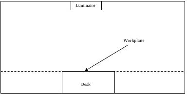
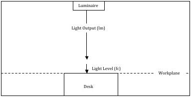
Light level, also known by its more technical name, illuminance, is the amount of light measured on the workplane in the lighted space. The workplane is an imaginary horizontal, tilted or vertical line where the most important tasks in the space are performed. People need minimum light levels to perform tasks efficiently, accurately and safely. The amount of light needed depends on the task. Measured in footcandles (fc) (or lux in metric), light levels are
Footcandles and Candlepower
Two important measurements of light are frequently confused—footcandles and candlepower.
Footcandles, expressed as lumens per square foot, measure the light that falls on a surface (illuminance). A footcandle minimum, for example, may be written into lighting specifications based on the Illuminating Engineering Society of North America’s (IESNA) recommended light level for a particular room or task.
Candlepower measures the intensity of a light source in a specific direction. Candlepower measurements are expressed in candelas and are independent of any object or surface that is being lighted.
FIGURE 1-2
The workplane is an imaginary horizontal, tilted or vertical line where the most important tasks in the space are performed. In this space, the workplane is the top of all the desks in the area, about 2.5 feet off the floor.
FIGURE 1-3
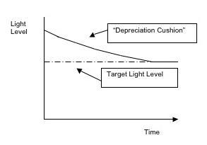
The “depreciation cushion.” Lighting systems are typically overdesigned so that they produce a higher initial light level than is really needed. This is because over time the lighting system will degrade in light output, so that over time it will produce a maintained light level.
either calculated or, in existing spaces, measured with a light meter. Footcandles can be produced as either initial or maintained quantities.
Initial Footcandles: Initial footcandles indicates a light level after new lamps are installed. This tells us how much light is reaching the workplane when the system is almost brand new.
Maintained Footcandles: Maintained footcandles indicates a light level after light loss factors, such as dirt and dust buildup on luminaire surfaces, are considered over a period of time. This tells us the real light level, since after some aging this is the light level we will be getting from the lighting system on an ongoing basis.
As a result of initial and maintained light levels, lighting designers typically design lighting systems that produce a higher light level initially than is needed, with the idea that over time the light level will settle down to the needed minimum. This extra light output built into the design is often called the “depreciation cushion.”
Minimum light levels are needed for humans to perform certain tasks at their best. The Illuminating Engineering Society of North
7
CHAPTER 1: LIGHTING FUNDAMENTALS
CHAPTER 1: LIGHTING FUNDAMENTALS
America (IESNA) has established recommended light level ranges for more than 600 tasks, published in its Lighting Handbook. It’s interesting to note that there was once a prevailing “more light, better sight” philosophy in applied illumination engineering in America for decades prior to the two energy crunches of the 1970s, based on Blackwell’s research on task performance and accuracy published by the IESNA in 1959. After this study, recommended light levels increased 200-500%, 30-70% higher than Western Europe.
Today’s recommended light levels are generally lower. Consider the timeline in Table 1-2, which reveals the progression of recommended light levels for office work.
One result of this is that many buildings constructed during the early 1970s are considered overlighted today, with a larger depreciation cushion, resulting in opportunities to upgrade existing lighting systems to reduce energy costs.
As can be seen in the timeline, the IESNA began making its recommendations more flexible in 1981, expressing its recommendation as a range instead of a single value. Finding the right light level in that range for a given application, in turn, is based on several factors: time, size, contrast, brightness and age.
The amount of time available to perform a task is critical in determining the proper light level. The less time there is to perform a task, the more light is required for that task to be completed efficiently and accurately.
Size matters when it comes to lighting tasks. The larger an object appears visually, the easier it is to see it. The smaller the task is visually, the more light is required to perform it properly.
Contrast deals with how well the task stands out from its immediate surroundings. Contrast is related to color. Blue and
Table 1-2.
Progression of recommended light levels for office work. Source: IES Lighting Handbook, 9th Edition.
yellow have the greatest contrast. The less contrast there is, the more light is required to complete the task as required. Contrast is also related to brightness. Too little or too much brightness decreases contrast.
Finally, the age of the worker must be considered. As the eye ages, vision capabilities typically deteriorate and so higher light levels are needed for older people. A 60-year-old man may need as much as 15 times more light than a 10-year-old child to perform the same task.
Why Is This Important? Planned lighting maintenance is focused on ensuring that people in a space get not only the minimum light levels they need, but the maximum light levels possible from the lighting system to avoid waste.
Lighting designers typically don’t design lighting systems with planned maintenance in mind. They assume spot relamping and no luminaire cleaning. As a result, they typically overdesign lighting systems, providing a large depreciation cushion.
With planned lighting maintenance, light levels will generally increase. This means the depreciation cushion can be reduced, presenting energy-saving lighting upgrade opportunities such as fewer luminaires, fewer lamps and/or lower-wattage lamps.
In addition, understanding light levels is important because as a lighting manager, you must be able to demonstrate to your customer the effects of planned lighting maintenance using a light meter. In a lighting upgrade, you will also not only be called on to record before/ after light levels with a light meter, but also predict light levels that will result from changing the existing lighting system.
Light Output
Light output is the quantity of light that is emitted from the lamp,
Table 1-3.
Typical light levels recommended by the IESNA. Source: Illuminating Engineering Society of North America.
RECOMMENDED LIGHT LEVEL IN FOOTCANDLES
Fine machine work 300 fc
8
Deskwork, intermittent reading and writing 30 fc
General
filing, mail room 30 fc
100 fc
100 fc
ACTIVITY
YEAR WORK LIGHT 1947
1954
office work, conference,
1959 Regular office work, reading good reproductions, filing, sorting
1966 Regular office work, reading good reproductions, filing, sorting
1972 General office work, bookkeeping, computer operation 150 fc 1981 Reading copied tasks, handwriting, keyboard reading 20-50 fc VISUAL
Lighting for safety 0.5-2 fc Lobbies 10 fc Stairways 5 fc Reading #2 pencil 30 fc Reading #3 pencil 50 fc
Inspection (simple-difficult) 30-500 fc Handcrafts 30-100 fc
measured in lumens (lm). Lamps are rated in both initial and mean lumens. Light output is often called lumen output. To avoid confusion, note that “light output” is a term also used to describe a luminaire’s light output, not just a lamp’s.
Initial Lumens: Initial lumens indicate how much light is produced once the lamp has stabilized; for fluorescent and high-intensity discharge (HID) lamps, this is typically 100 hours.
Mean Lumens: Mean lumens indicate the average light output over the lamp’s rated life, which reflects the gradual deterioration of performance due to the rigors of continued operation; for fluorescent lamps, this is usually determined at 40% of rated life.
Why Is This Important? When we say “light level,” we are basically saying “light output spread out over an area”—in other words, how much light output strikes each square foot in the space and is then reflected and recorded as footcandles. Light level is an expression of light output once it strikes and is reflected from an object.
A big part of planned lighting maintenance—group relamping—is designed to address lamp lumen depreciation, a significant light loss factor caused by the fact that all lamps produce less light over time as they age. By understanding light output, you can relate the impact of group relamping schedules to light levels.
In addition, lighting managers often recommend new lamps, ballasts and other lighting options to their customers. To make the best recommendations and be able to justify them, as a lighting manager you should be able to relate the light output of these new options to changes in light levels in the space.
Light Loss Factors
Lighting systems are designed to convey light from a lamp or luminaire (light output) to the workplane, where it is used (light level). A number of factors degrades the amount of light that reaches the workplane, which are called light loss factors. These factors may be considered recoverable or non-recoverable.
Non-recoverable light loss factors, such as ballast factor, are largely out of the control of lighting managers.
Recoverable light loss factors, such as lamp burnouts, lamp
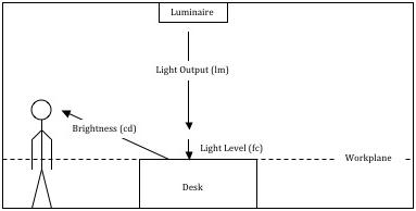
FIGURE 1-4
The luminaire produces light output in lumens, which then reaches the workplane and is measured in footcandles. Footcandles are an expression of lumens spread out over an area. People need a minimum number of footcandles to perform given tasks efficiently, accurately and safely.
lumen depreciation and luminaire dirt depreciation, can be mitigated through planned lighting maintenance.
Lamp Burnouts (LBO): Eventually, all lamps essentially fail to relight and need to be replaced. Large groups of lamps tend to fail at a predictable rate. The rate of failure depends on the lamp. If the rated life of a given lamp is 20,000 hours, we know that after 20,000 hours of operation, 50% of a large group of lamps will have failed, and the other 50% will still be lit. The rate of failure for a particular lamp is shown on the lamp’s mortality curve.
Lamp Lumen Depreciation (LLD): Lamps produce less and less light over time than when they are new. The percentage of decline of light output is called lamp lumen depreciation. The percentage of light output the lamp produces over time is called the lamp’s lumen maintenance. The rate of decline is predictable on a lumen
POINT SOURCE AND DIFFUSE SOURCE
When selecting a lamp for a given application, it is important to determine whether a point source or a diffuse source is more appropriate. A point source is a lamp or luminaire that is relatively small compared to the area it is lighting and has the potential to direct a concentrated beam of light on a specific surface or object.
Incandescent, halogen and HID lamps are typically used in point source applications. A diffuse source, on the other hand, is relatively large and spreads light over a wide area. Linear fluorescent lamps are the most common diffuse source lighting.
FIGURE 1-5
BEAM ANGLE AND FIELD ANGLE
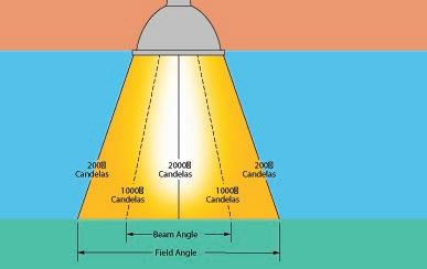
The pattern of light delivered by reflector lamps—a popular point source—is often described in terms of Beam Angle and Field Angle. Beam Angle is the smaller figure, and refers to that portion of the lamp’s beam where the candlepower is greater than 50% of the candlepower measured at the center of the beam. The Field Angle describes the larger area of a beam where the candlepower is greater than 10% of the center beam candlepower.
9
CHAPTER 1: LIGHTING FUNDAMENTALS
CHAPTER 1: LIGHTING FUNDAMENTALS
maintenance curve and can vary depending on the lamp type.
Luminaire Dirt Depreciation (LDD): Because luminaires contain electrical devices and generate heat, they attract dirt and dust. Because dirt and dust absorb light instead of reflect it, they reduce the luminaire’s light output. The extent of dirt depreciation depends on several factors, including the luminaire’s design and the amount of dirt and dust in the building. A factory typically has a lot more dirt and dust flying around than an office.
Light loss factors are typically expressed as decimal numbers showing the percentage of light output getting to the workplane after the light loss “tax” is paid. So a given LLD might be 0.90, meaning that as the lamp ages to a certain point, it will only produce 90% of its rated initial light output.
Why Is This Important? Planned lighting maintenance addresses recoverable light loss factors through group relamping (lamp burnouts, lamp lumen depreciation) and luminaire cleaning (luminaire dirt depreciation).
As a result, more light reaches the workplane, raising light levels and delivering the maximum amount of light per dollar.
If a customer accepts reactive maintenance and lower light loss factors, he is basically saying that it’s okay to waste money on producing light that never reaches the workplane to be used. This is like paying 20% of his workforce to sit around all day and not work. Not a good business strategy!
FIGURE 1-6
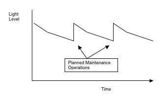
Because of light loss factors, the amount of light output is reduced, with the amount of reduction increasing over time unless addressed by maintenance. Planned maintenance, in particular, can have a dramatic impact on light levels, as shown here.
This formula is incomplete, though. We should break it out further and make it more practical by including light loss factors. Here’s the same formula, in greater detail, expressed three different ways:
Average Maintained Light Level (Footcandles) = (Lamps/Luminaire x Lumens/Lamp x No. of Luminaires x Coefficient of Utilization x Light Loss Factor) ÷ Area in Square Feet
Average Maintained Light Level (Footcandles) = (Total Lamps x Lumens/Lamp x Coefficient of Utilization x Light Loss Factor) ÷ Area in Square Feet
Average Maintained Light Level (Footcandles) = (Lamps in One Luminaire x Lumens/Lamp x Coefficient of Utilization x Light Loss Factor) ÷ Area in Square Feet/Luminaire
How do I get the “Light Loss Factor”? Light loss factors are typically combined in lighting design calculations, simply by multiplying them. So to get the overall light loss factor (LLF) to do lighting design calculations, we multiply them to get a single number.
Light Loss Factor (LLF) = Ballast Factor x Luminaire Ambient Temperature Factor x Supply Voltage Variation Factor x Lamp Position Factor x Optical Factor x Lamp Burnouts Factor x Lamp Lumen Depreciation Factor x Luminaire Dirt Depreciation Factor x Room Surface Dirt Depreciation Factor
For example: 0.80 x 0.75 x 0.95, etc. = 0.73 LLF
How do I get “Coefficient of Utilization”? Coefficient of utilization (CU) is similar to light loss factors, but has to do more with the luminaire’s design and location, and the room itself. The CU value shows the percentage of lumens that reach the workplane after light is lost due to the luminaire’s efficiency at transmitting light, the room proportions, the mounting height of the luminaire, the height of the task, and the ability of room surfaces to reflect light. Lighting designers use CU to predict light levels that will be produced by a specific lighting system mounted in a defined room.
The CU value is found in a table published in the luminaire’s photometric report.
Example: In our previous example, we have a 5,000-square-foot space and 50 luminaires producing 3,000 lumens each. Now we can apply a CU of 0.65 and LLF of 0.75:
Predicting Light Levels
A footcandle is one lumen of light density per square foot. Using this fact and some simple math, we can predict light levels resulting from a given lighting system by knowing its light output:
Light Level (fc) = Light Output (lm) ÷ Area in Square Feet
So if we have 50 luminaires each producing 3,000 lumens, our total light output is 150,000 lumens. If these 50 luminaires are in a space that is 5,000 square feet, then our light level is:
Light Level (fc) = 150,000 ÷ 5,000 = 30 fc
Average Maintained Light Level (fc) = (50 x 3,000 x 0.65 x 0.75) ÷ 5,000
Average Maintained Light Level (fc) = 15 fc
As you can see, by adding CU and LLF to our formula, the light level in our example has been cut in half from 30 fc to 15 fc. More typically, lighting designers have to work backwards from the workplane, not forwards from the lighting system, however. In other words, the lighting designer first determines the average maintained light level needed for a space, then can calculate the
10
number of luminaires or lamps required and the required light output per luminaire or lamp.
Below are some helpful formulas:
Required Light Output/Luminaire (Lumens) = (Target Maintained Light Level in Footcandles x Area in Square Feet) ÷ (Number of Luminaires x Coefficient of Utilization x Light Loss Factor)
Required No. of Luminaires = (Desired Average Maintained Light Level x Area in Square Feet) ÷ (Lumens/Lamp x Lamps/Luminaire x Coefficient of Utilization x Light Loss Factor)
Required No. of Lamps = Required Lumens ÷ Initial Lumens/Lamp
Why Is This Important? When a customer says—“Planned maintenance and saving energy sounds like a good idea, but what’s the best approach, and how will it affect my building?”— you will have a rough answer.
Lighting managers often use light level calculations to predict the impact of planned lighting maintenance and energy-saving lighting upgrades. By doing the math, you can try out different options and see what will happen before committing to anything. You can also show customers the impact of each option, and guide them to the best option for their building.
Uniformity
In review, the lighting luminaire’s primary job is to house and protect the light source and other vital components, connect the system to a power source, and distribute the light in a controlled pattern. Light distribution enables the designer to control the spread of the beam, its intensity, and the shape and clarity of the pattern of light it creates.
For many commercial lighting applications, uniformity is important in terms of light level and brightness. When uniformity is desired, the light must be distributed roughly evenly across the workplane. If we were to take a light meter and measure light level on one desk, for example, we should get a similar reading on every other desk in the room.
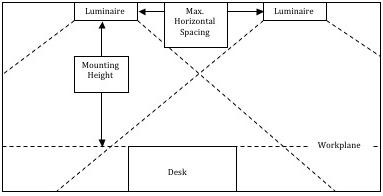
FIGURE 1-7
In many commercial applications, uniformity is good lighting design. To achieve uniformity, designers use the manufacturer-supplied spacing criterion for the luminaire type, which they multiply by the luminaire’s mounting height to gain the maximum horizontal spacing between the luminaires.
CHAPTER 1:
LIGHTING
FUNDAMENTALS
Why is uniformity important? The eye’s focus tends to drift towards the brightest object in the field of view. Brightness grabs attention. In some applications, this is a good idea. For example, using this principle, we can focus attention on key merchandise in a store and use lighting’s role as the “silent salesman.” However, eventually a lack of uniformity can be visually tiring, which we don’t want in many applications, such as offices. In offices and similar spaces, uniformity is a good idea. It may be boring visually, but it is not fatiguing.
In commercial applications such as office spaces, a lack of uniformity may also mean that some people are getting more light than they need and some not getting enough. And non-uniform lighting can create a low-quality appearance of the space due to shadows on walls and patches of light on floors.
Designers achieve uniformity primarily through spacing the luminaires properly. If you have 10 luminaires mounted in the ceiling and six of them are clustered together and four are on the other side of the room, you’re not going to have uniform light levels. The luminaires must be spaced according to manufacturer instructions—specifically, the manufacturer-supplied spacing criterion, which is in the luminaire’s photometric report. The spacing criterion is typically between 0.5 and 2. To get the maximum recommended spacing between each luminaire to ensure uniformity, follow the formula below:
Maximum Horizontal Spacing Between Luminaires (ft.) = Spacing Criterion x Vertical Distance Between the Luminaire and the Workplane (ft.)
Why Is This Important? Changing existing luminaires can affect uniformity. For example, retrofitting a luminaire to remove the clear plastic lens and install a low-glare louver may reduce uniformity because the luminaire’s distribution will be different. In this case, the louver will direct more of the light straight down, meaning the light level between the luminaires may be reduced to unacceptably low levels. This can also occur with specular reflector installations. In these situations, it is often a good idea to conduct trial installations for this type of equipment to determine the effects on uniformity before committing to a complete installation. One solution, in this case, is to move the luminaires closer together.
QUALITY OF LIGHT: BRIGHTNESS, COLOR
Quality of light is largely a function of visual comfort and perception of the lighted space. While providing minimum needed light levels is the primary goal of many lighting applications, quality of light issues are also vitally important. While quantity of light is essential for sight, quality of light is essential for what we see, and how comfortable it is to see it.
Brightness
Brightness, also called photometric brightness or by its technical name, luminance, is the light that we can actually “see.” Brightness can be measured as the light leaving a lamp, or the light reflecting from an object’s surface. It is measured in footlamberts or candelas/ sq.ft. (English) or candelas/square meter (metric).
Brightness can be used for a variety of purposes, from producing a
11
CHAPTER 1: LIGHTING FUNDAMENTALS
FIGURE 1-8
Brightness is the light that we can actually “see,” and can be measured as the light leaving a lamp or the light reflecting from an object’s surface.
Strategies for Reducing Unwanted Glare: Strategies commonly employed to reduce unwanted levels of glare include:
• Indirect lighting that throws more light upward than downward, diffusing the light and reducing glare on computer screens.
• Parabolic louvers, special lenses or other diffusing media on luminaires that diffuse the luminaire’s light output.
• In an office, it may be possible to de-emphasize the ambient lighting system with reduced light output and diffusing media, while providing adjustable task luminaires at workstations.
• Relocating the light source.
sense of drama to creating sparkle and glitter elements in a space. For the common purpose of getting work done, the brighter a task is, the easier it is to see and the lower the amount of light that is required. If not controlled, however, brightness can produce levels of glare that either impair or prevent a desired task being performed. Glare can be described as direct or reflected glare, which can then result in discomfort or disability.
Direct glare comes straight from the light source.
Reflected glare shows up on the task itself, such as a computer screen.
Discomfort glare does not prevent seeing but makes it uncomfortable.
Disability glare prevents vision. A popular example is holding a glossy magazine at a certain angle; a veiling reflection results, impairing our reading of the page.
Visual Comfort Probability (VCP): Visual comfort probability (VCP) ratings for luminaires, found in luminaire manufacturers’ photometric test reports, can help designers specify luminaires that can provide a more comfortable visual environment. VCP is a rating on a scale of 0-100 given to indoor luminaires in a uniform system, with all luminaires being identical, a situation that is commonly found in grid layout office lighting systems. A VCP rating of 75 indicates that 75% of the occupants in the poorest location would not be irritated by direct glare. Generally, office environments require that luminaires have a VCP rating of 70-80 or more.
Note that some VCP tables take into account room size and offer separate VCP ratings based on whether you are looking along the lamps (your line of sight is parallel to the lamps) or across the lamps (your line of sight is perpendicular to the lamps).
Note that while parabolic louvers offer the best VCP ratings, caution should be observed in the specification of small-cell parabolics, as it is difficult for some people to be able to tell that the luminaire is on from a distance. This can produce a “cave effect,” affecting occupants’ satisfaction with the space. They also have a low efficiency.
• Relocating the task or changing its orientation until the glare is removed.
Table 1-4.
Shielding media characteristics for fluorescent 2x4 recessed troffer luminaires. Note that higher VCP requires light diffusion, which reduces efficiency in delivering light to the task; generally, the higher the VCP rating, the lower the luminaire’s efficiency in transmitting light to the workplane. With a small-cell parabolic louvered luminaire, up to 65% of the light produced by the lamps never gets to the workplane.
SHIELDING MEDIUM LUMINAIRE EFFICIENCY VCP RATING
Clear Prismatic Lens 60-75% 50-70
Low-Glare Clear Lens 60-75% 75-85
Deep-Cell Parabolic Louver 50-70% 75-95
Translucent Diffuser 40-60% 40-50
Small-Cell Parabolic Louver 34-45% 99
Brightness Ratios: Brightness ratios in a space can affect how it is perceived. While high ratios of bright to dark in the space can produce contrast or a sense of drama, it can also be visually fatiguing during transient adaptation, which describes the eye adapting to changes in brightness. This can reduce productivity and can even be hazardous. Like light levels, in many applications it is advantageous to have uniform levels of brightness, too.
Distribution: Traditionally, lighting designers focused the distribution of light onto the workplane, where most of the tasks are done. However, a number of lighting designers now view the entire lighted space as a complete visual, luminous environment. In typical office and many other applications, additional lighting, such as uplighting on walls and ceiling, particular at room edges, can create a brighter, more interesting space. People tend to view such spaces as larger. Industry guidelines indicate that light washing over the ceiling plane creates a comfortable, uniform brightness for working.
12
Light & Color
As discussed earlier, visible light—made up of a spectrum of colors that combine to create white light—cannot be seen. If we turned on a flashlight in a dark room, the beam of light we are seeing is actually light being reflected from a multitude of dust particles in the air. Therefore, we see objects only when light is reflected or emitted from them. And that is how we see color.
All objects are chemically oriented to absorb certain wavelengths of light and reflect others. The ones that are reflected are perceived by the human eye to be the color of the object. A red object being struck by visible white light will absorb all wavelengths except red, which is reflected, and so we see the object as red. A pure white object reflects all wavelengths and absorbs none. A pure black object absorbs all wavelengths and reflects none. This is where a great amount of art comes into lighting because
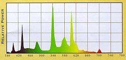
Figure 1-9.
Spectral Power Distribution Curve for a 4100K fluorescent lamp with a triphosphor (red, blue, green) coating to improve color rendering. Numbers shown at the bottom are in nanometers. Courtesy of Osram Sylvania, Inc.
CHAPTER 1: LIGHTING FUNDAMENTALS
few lamp types produce pure white light. Some lamps produce light that is saturated in blue and green, others red and yellow. A red object struck by light that contains only blue and green wavelengths would not appear red as if it were under sunlight. A low-pressure sodium lamp produces light saturated in yellow, which means that all objects struck by it will appear yellow, black or a shade of gray. The major lamp manufacturers all have literature and exhibits that demonstrate the effect of light on color. The slogan of one: “Color is how you light it.”
To understand how a lamp’s light will affect the color of objects in the space, three methods are used, including spectral power distribution, color temperature and color rendering. All of this information can be found on the manufacturer’s spec sheet.
Spectral Power Distribution: Spectral power distribution shows the visible light spectrum and the wavelength composition for the light from the lamp (see Figure 1-9). The spikes indicate that the light is stronger in revealing certain colors.
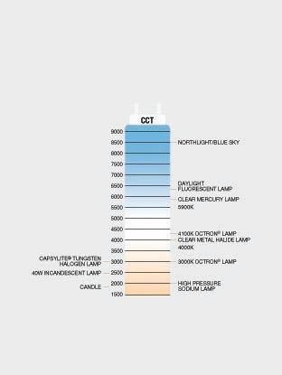
Color Temperature: Color temperature, expressed on the Kelvin scale (K), is the color appearance of the lamp itself and the light it produces.
Imagine a block of steel that is steadily heated until it glows first orange, then yellow and so on until it becomes blue or bluishwhite. At any time during the heating, we could measure the temperature of the metal in Kelvins (Celsius + 273) and assign that value to the color being produced, resulting in a “color temperature.” Computer software performs this function for today’s lamps, giving them a color temperature rating found in the manufacturers’ literature.
For incandescent lamps, the color temperature is a “true” value;
Table 1-5.
13
COLOR TEMPERATURE WARM NEUTRAL COOL DAYLIGHT KELVIN RANGE 2600-3400K 3500K 3600-4900K >4900K ASSOCIATED EFFECTS & MOODS Friendly Intimate Personal Exclusive Friendly Inviting Non-threatening Neat Clean Efficient Bright Alert Exacting Coloration APPROPRIATE APPLICATIONS Restaurants Hotel Lobbies Boutiques Libraries Office Areas Retail Stores Public reception areas Showrooms Bookstores Office areas Office areas Conference rooms Classrooms Mass merchandisers Hospitals Galleries Museums Jewelry stores Medical exam areas Printing companies
Influence of color temperature on mood and lighting applications. Courtesy of Philips Lighting Company.
CHAPTER 1: LIGHTING FUNDAMENTALS
for fluorescent and high-intensity discharge (HID) lamps, the value is approximate and is therefore called correlated color temperature. In the industry, both terms—color temperature and correlated color temperature—are often used interchangeably. The color temperature of lamps makes them visually “warm,” “neutral” or “cool” light sources.
Lamps with a lower color temperature (3500K or less) have a warm or red-yellow/orangish-white appearance. The light is saturated in red and orange wavelengths, bringing out warmer object colors such as red and orange more richly.
and the light emitted from it. Color rendering describes how well the light renders colors in objects.
However, the two metrics are interconnected in a very important way: To compare the CRI ratings for any two given lamps, they must have the same color temperature for the comparison to have any meaning. Similarly, when replacing lamps during group relamping, be sure that all of the color characteristics match.
When specifying color characteristics for a lamp, numerous psychological factors must be considered depending on the lighting goals for the space.
Warm light sources are generally preferred for the home, restaurants and retail applications to create a sense of warmth and comfort, while neutral and cool sources are generally preferred for offices and similar applications to create a sense of alertness.
In addition, in retail applications, color is a critical design decision because buyers need to be able to choose products of the correct color, both to enhance the chance of its sale and to reduce the chance of it being returned once the buyer gets outside and sees it under sunlight. In this or any other application where the occupant needs to see the right color, good color quality is essential.
In other applications such as parking lots, color is not an important factor, so lower-color-rendering lamps can be specified.
YOU’RE READY
Congratulations. If you score well on the Lighting Fundamentals Quiz, consider yourself well on your way to becoming a lighting expert. Now you’re ready take on the next chapter: Planned Lighting Management.
and blue more richly.
Color Rendering: Color rendering, expressed as a rating on the Color Rendering Index (CRI), from 0-100, describes how a light source makes the color of an object appear to human eyes and how well subtle variations in color shades are revealed. The higher the CRI rating is, the better its color rendering ability.
Standard incandescent lamps enjoy a CRI rating of 100. Fluorescent lamps are in the range of 52 to 95, depending on the lamp. Advances in phosphor technology have enabled fluorescent and HID lamps to advance greatly in color rendering.
Notes on Color: A common misperception is that color temperature and color rendering are the same; they are not. Color temperature describes the color appearance of the light source
14
LIGHTING FUNDAMENTALS QUIZ
Check your understanding of this chapter’s material by completing these multiple-choice questions. The answers are on Page 82.
1. What percentage of human impressions of the world are visual?
a) 50% b) 60% c) 70-75% d) 80-85%
2. The QUANTITATIVE aspect of light primarily deals with____.
a) Light distribution b) How much light is available at the task c) Availability of daylight d) All of the above
3. The QUALITATIVE aspect of light primarily deals with____. a) Color of the light b) Light distribution c) Ensuring there is no glare d) All of the above
4. Workplace studies have shown that ____.
a) Worker satisfaction is economically important b) Workplace characteristics have a significant impact on worker satisfaction
c) A majority of office workers are unsatisfied with their lighting d) All of the above
5. 5. What metric is used to measure light output?
a) Footcandles b) Lumens c) Candelas/sq.ft. d) Lumens per watt
6. What metric is used to measure light levels?
a) Footcandles b) Lumens c) Candelas/sq.ft. d) Lumens per watt
7. What metric is used to measure brightness?
a) Footcandles b) Lumens c) Candelas/sq.ft. d) Lumens per watt
8. What is the workplane?
a) An imaginary horizontal, tilted or vertical line where the most important tasks in the space are performed b) An imaginary horizontal, tilted or vertical line intersecting every task in the space c) (a) and (b) d) None of the above
9. What is the difference between initial and maintained light levels?
a) Initial is when the new lamps are installed; maintained is after light loss factors such as dirt and dust are considered over a period of time
b) Initial is when the new lamps are installed; maintained is after luminaire cleaning and/or group relamping c) Initial is the “depreciation cushion”; maintained is after luminaire cleaning and/or group relamping d) None of the above
10. Since 1959, have light level recommendations generally been increasing or decreasing? a) Increasing b) Decreasing
11. Which of the following is NOT an important factor in determining what light level is appropriate for a given task?
a) Size of the task b) Age of the worker performing the task c) Gender of the worker performing the task d) Contrast between the task and its immediate surroundings e) The amount of time available to perform the task
12. Which of the following is NOT a recoverable light loss factor?
a) Lamp burnouts b) Lamp lumen depreciation c) Luminaire dirt depreciation d) Supply voltage depreciation
13. Suppose we have 10 luminaires each producing 5000 lumens in a space that is 1000 square feet. What is the light level in the space?
a) 5 footcandles b) 30 footcandles c) 50 footcandles d) 60 footcandles e) 100 footcandles
14. Suppose we have 10 luminaires each producing 5000 lumens in a space that is 1000 square feet. Now suppose we calculate our light loss factors to be 0.60. What is the light level in the space?
a) 5 footcandles b) 30 footcandles c) 50 footcandles d) 60 footcandles e) 100 footcandles
15 CHAPTER 1: LIGHTING FUNDAMENTALS
CHAPTER 1: LIGHTING FUNDAMENTALS
15. What are the consequences of a lack of uniformity of light levels in an office?
a) Non-uniform lighting can be visually fatiguing b) Some people are getting enough light but others aren’t getting enough c) (a) and (b) d) None of the above
16. Uncontrolled brightness is called glare. Glare is a sign of poor lighting. There are several types of glare effects. For example, what is direct glare?
a) Glare that comes straight from the light source b) Glare that shows up on the task itself, such as a computer screen
c) Glare that does not prevent seeing but makes it uncomfortable d) Glare that prevents vision
17. Which of the following is NOT a recommended method for dealing with glare?
a) Parabolic louvers or other diffusing media b) Indirect lighting c) Removing lamps from offending luminaires d) Relocating the task or the light source
18. A lamp with a 4000K color temperature is considered a ____ light source.
a) Warm b) Neutral c) Cool d) Daylight
19. Generally, high pressure sodium, low pressure sodium and incandescent lamps are considered ______light sources. a) Warm b) Neutral c) Cool d) Daylight
20. Lamp A has a CRI rating of 50 and a color temperature of 4000K. Lamp B has a CRI rating of 60 and a color temperature of 3500K. Which lamp has better color rendering ability?
a) Lamp A b) Lamp B c) Impossible to tell d) Possible to determine, but need to know nominal lamp watts
16
CHAPTER 2: PLANNED LIGHTING MANAGEMENT
LIGHTING MAINTENANCE
Lighting maintenance is essential because the performance of all lighting systems deteriorates over time, which affects light levels and the appearance of the spaces they light. Lighting components fail and must be replaced. Declining light levels, lamp burnouts and color shift can affect the visual appearance of the space and contribute to an unsafe and/or unproductive environment. Dirt and dust accumulation on luminaires will steadily reduce the quantity of light that reaches the workplane. Maintenance can mitigate all of these problems.
There are two ways to conduct maintenance. One method, reactive maintenance, is to simply respond to problems as they occur. The second method, planned or proactive maintenance, is to organize labor and resources to prevent problems before they occur, maintaining systems more efficiently. Planned maintenance is more effective and offers a managed platform for continual lighting optimization.
Planned maintenance benefits are based on three advantages. First, maintenance should have an objective of “keeping it working like new” versus “keeping it running.” Second, all maintenance work should be planned out and scheduled. And third, maintenance work should be combined to economize on labor and resources. Virtually all planned maintenance programs include scheduled group relamping, luminaire cleaning and troubleshooting/inspection and repair.
Compared to reactive maintenance, planned maintenance reduces operating costs, maximizes light levels, reduces waste, can improve safety and security, economizes on resources, and can maintain designed space appearance.
Luminaire Cleaning
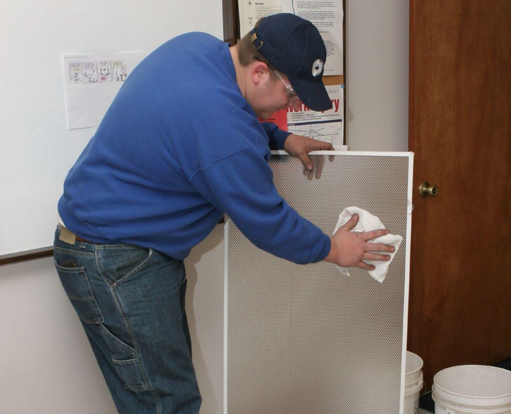
Cleaning the lighting system typically means removing dirt and dust from lamps and luminaires.
Cleaning lamps and luminaires maximizes lumen output by minimizing light loss due to absorption of light by accumulated dirt and dust, referred to as Luminaire Dirt Depreciation (LDD). Luminaire cleaning increases the reflectance of interior luminaire surfaces, enables lenses to transmit more light, and helps maintain the luminaire’s intended light distribution.
Cleaning can be combined with group relamping, inspection, repair and energy-efficient lighting upgrades to maximize cost effectiveness.
Group Relamping
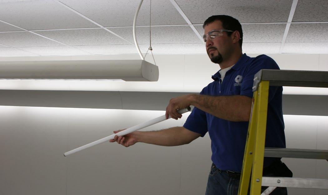
Group relamping is the practice of replacing all lamps in a lighting system at scheduled intervals rather than individually as they fail. Benefits include lower maintenance costs, consistent visual appearance, and minimized disruption to operations.
Why dispose of operating lamps? It is more economical overall to replace all lamps at planned and scheduled intervals rather
FIGURE 2-1
Luminaire cleaning raises light levels and helps maintain the luminaire’s intended light distribution. Courtesy of Colorado Lighting, Inc.
Table 2-1.
Common luminaire materials and cleaning compounds used to clean them. Source: Illuminating Engineering Society of North America.
LUMINAIRE MATERIAL
OKAY TO USE WITH AVOID USE WITH
Aluminum Very mild soaps and cleaners followed by thorough rinse of clean water
Glass Most nonabrasive cleaners and detergents, followed by rinsing
Plastics Antistatic compounds; vacuuming is most effective for drying
Silver Film (often coated with plastic or acrylic)
Porcelain Enamel
Nonabrasive solution of mild liquid detergent and water with a soft, damp rag
Strong alkaline cleaners
Dry wiping or dripdried after application of the rinse solution
Nonabrasive cleaners, such as detergents and most glass cleaners
Synthetic Enamel Detergents
Some strong cleaners, alcohol and abrasive cleaners
17
CHAPTER 2: PLANNED LIGHTING MANAGEMENT
CHAPTER 2: PLANNED LIGHTING MANAGEMENT
FIGURE 2-2
Group relamping economizes on labor and resources while improving the appearance of a space. Courtesy of Colorado Lighting, Inc.
Applications
Planned lighting maintenance can produce substantial benefits in most applications, but is especially beneficial in:
• Installations where lamps operate on the same schedule, which makes the mortality rate easier to predict.
• Installations with difficult access or hard-to-reach mounting heights.
• Metal halide lamp installations to minimize color shift and possibility of non-passive failure at end of life.
• High pressure sodium installations to minimize end of life cycling.
• Environments with high levels of dirt and dust.
• Buildings in which luminaires are being upgraded in a manner that will reduce light levels.
• Fluorescent VHO lamp installations to compensate for high lamp lumen depreciation commonly experienced by these lamps as they get close to end of life.
than one at a time. It may take 50 hours to replace 100 lamps individually versus about 10 hours to group relamp them. Group relamping can reduce labor costs by as much as 80%. If (the labor cost of spot-replacing one lamp) – (the labor cost of replacing the same lamp in a group relamp scenario) > (the cost of a new lamp), then group relamping makes good economic sense.
Group relamping doesn’t always boil down to labor costs. All lighting technologies experience lumen depreciation as they mature. Each product family has its own specific rated life and lumen depreciation curve, based on reference conditions. It is important to understand other factors that influence both the rated life and lumen depreciation curve, such as luminaire dirt depreciation and the effects of the surrounding environment. Factors such as high ambient heat, frequent switching of less than 3 hours per start and voltage fluctuations all affect lamp life and lumen output.
In the case of metal halide lamps, color shifting can occur near end of life, disrupting uniformity and reduced lumen output. Group relamping ensures that there is maximum lamp-to-lamp color uniformity and lumen output. Additionally, greatly extending the use of metal halide lamps beyond the manufacturer’s rated life could contribute to a non-passive end of life failure, creating a safety hazard.
In the case of high pressure sodium and pulse start metal halide lamps, group relamping can reduce end-of-life cycling (automatic turning on and off of lamp) and subsequent wear and tear on the starter and ballast.
In all cases, group relamping adds convenience and efficiencies, most notably when these lamps are in difficult-to-access areas.
Group relamping projects can be scheduled after normal working hours, minimizing disruption to operations for your customer while gaining operational efficiencies for the installing contractor. Projects can become more economical when group relamping is combined with luminaire cleaning, inspection, repair or upgrades to energyefficient lighting, such as relamping to a lower wattage lamp or lamp and ballast retrofits.
• Indirect lighting installations, where luminaires are highly dependent on reflectances of luminaire and room surfaces to deliver light from the lamps to the workplane.
MAINTENANCE INTERVALS
A maintenance interval is the point at which maintenance is conducted. If the group relamping interval is three years, then every three years, group relamping will be performed. Finding the right interval for group relamping and luminaire cleaning requires analysis of a number of variables.
REMEMBER
Group relamping and luminaire cleaning can reduce labor costs while improving the visual appearance of a space and provide an opportunity to inspect and troubleshoot any problems with the lighting system. These operations can be combined with energy-saving lamp/ballast retrofits to provide an economical project.
Luminaire Cleaning Interval
One way to determine the best luminaire cleaning interval is the point at which the cost of lost delivered lumens equals the cost of cleaning.
As dirt and dust accumulate on luminaire surfaces, they increasingly absorb light instead of reflecting it, while the owner still requires the designed lumen output and is still paying to run the lamps. This means the owner is paying the same amount of money to operate lamps from which he is getting less and less delivered lumens. When the amount of this wasted money equals the cost of cleaning the luminaire, then the luminaire should be cleaned. If the owner waits even longer, the cost of doing nothing may exceed the cost of luminaire cleaning, which means the owner is essentially throwing money away.
More frequent cleanings may be required when the lighting system is upgraded to an energy-saving lighting system (lower-wattage lamps and ballasts and/or fewer luminaires) that produces less delivered lumens. By using luminaire cleanings as a lighting
18
management tool, you can optimize delivered lumen output per luminaire, providing more flexibility in reducing the number of luminaires, lamps and/or system watts.
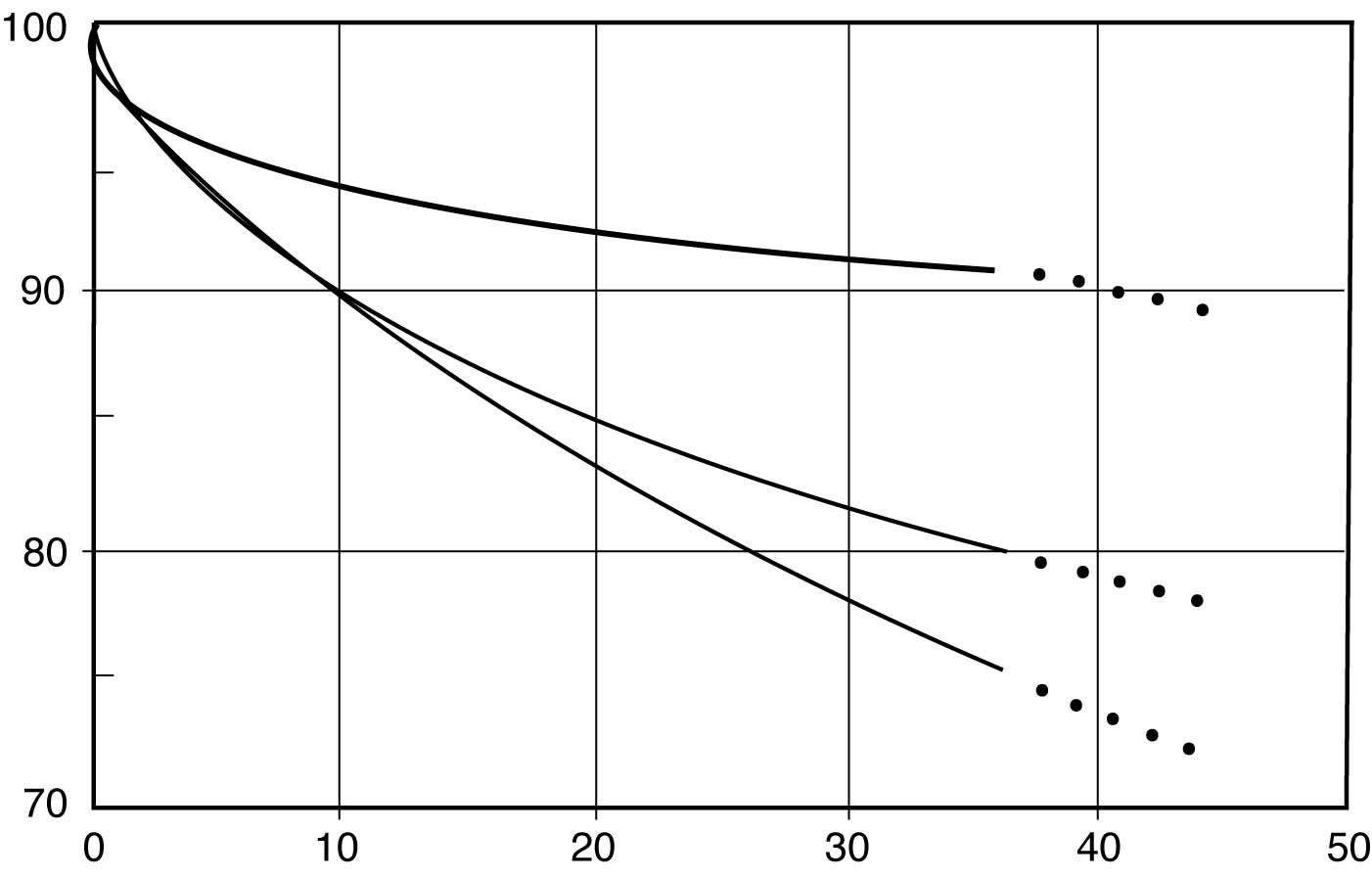
FIGURE 2-3
Luminaire dirt depreciation (LDD) curves for various luminaires. The left axis shows percentage of light escaping the luminaire; the bottom axis shows time in months. As can be seen, light output from a luminaire steadily decreases over time based on a number of factors, including the luminaire type and how much dirt is present in the space. The bottom line is that the lighting system’s owner ends up paying for light that never leaves the luminaire. By cleaning the luminaire, more usable light will be produced.
REMEMBER
The ideal group relamping interval is usually 70-80% of rated lamp life for fluorescent lamps, the point at which the lamp morality rate accelerates significantly.
not fail, but produces continually diminishing lumen output while remaining lit. The lumen depreciation can continue to the point that it is no longer worth operating. An example is a mercury lamp that continues to light, but has become extremely dim due to lumen depreciation. Useful life can be defined several different ways, therefore. One way is if the lamp has depreciated to 50% of its initial light output. Another is if the lamp has undergone significant color shift. A final way is if the lamp is cycling, displaying end of life characteristics or experiencing operational issues. Lamps that remain lit although they have passed their useful life should be replaced.
MANAGING A FIELD CREW
Successful maintenance operations require careful planning to avoid problems, addressing concerns such as:
1. Door and space size, ground or loading dock level access, and elevator load capacities which will determine how maintenance equipment will be moved in and out of the space.
REMEMBER
Luminaire cleaning increases average light levels, sometimes higher than the recommended minimum, providing opportunities to install new lamps and ballasts that in turn reduce light levels and reduce energy costs. The ideal time to clean the luminaires is when operating them without cleaning results in paying for wasted light.
Group Relamping Interval
Given a typical fluorescent lamp’s mortality curve, at 100% of the lamp’s rated life, one-half of a large group of lamps can be expected to fail. One-half fail before, and one-half fail afterwards. The rate of failure, however, escalates sharply after 70-80% of rated life. As a rule of thumb, 70-80% of rated life is a suitable group relamping interval. This can be assigned to a calendar interval (e.g., every three years).
From an economic standpoint, the optimal group relamping interval can be calculated based on two factors: the cost of spot relamping and the cost of group relamping. As the failure rate accelerates, group relamping becomes less expensive than spot relamping. Group relamping is more attractive when lamps are low cost and spot replacement labor is expensive. Computer software is available that can help calculate the optimal group relamping interval.
Group relamping intervals may not always be calculated solely on the lamp’s mortality rate. For some lamp types, the lamp does
2. On-site storage for materials and equipment. Including proximity to work area(s), security for tools and equipment left on site for the duration of the project, and access to electrical outlets to recharge battery operated lifting equipment.
3. Floor tolerances, which will determine the weight of maintenance equipment that can be moved onto floor areas.
4. Location in the building where maintenance will be performed.
5. How luminaires can be accessed for maintenance.
6. How the space is used, hours of occupancy and scheduled work shift. Of particular concern is whether the space will be occupied when maintenance operations are scheduled.
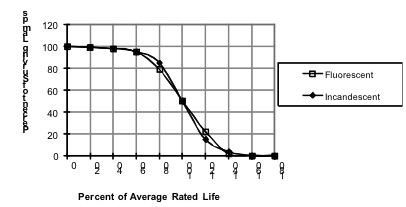
FIGURE 2-4
Typical mortality curve for fluorescent lamps. Large groups of lamps tend to follow this curve. Since most lamps start failing after 70-80% of lamp life, it makes economic sense to replace all of the lamps in the system at the same time as compared to replacing subsequent failures individually, resulting in significant labor savings. Courtesy of the Lighting Design Lab.
19
CHAPTER 2: PLANNED LIGHTING MANAGEMENT
CHAPTER 2: PLANNED LIGHTING MANAGEMENT
7. Any site-specific security requirements, background checks required, etc.
8. All safety requirements, including documentation and whether a site orientation is required (and if so, when is the orientation offered).
When you are promoted to crew manager, you will have the satisfaction of this advancement, combined with the challenges and rewards of new responsibilities. Not only are you responsible for your own actions, but for the actions of your crew. You are representing your employer and yourself. Here are some general tips for managing a crew:
1. Your first responsibility is to the safety of your crew, your customer and their employees and customers. Follow all applicable safety rules and regulations.
2. Set a good example. Remember that you are in your customers’ facility by invitation, and you are completely accountable to your customer and your employer. Great first impressions can earn respect and develop long-term relationships. These relationships may lay the groundwork for future maintenance agreements, expansion in product offerings as well as provide priceless future referrals. You will be recognized and appreciated for your ethical and professional conduct, as well as the value of the service offerings your company provides.
3. Make sure all team members understand their individual responsibilities and team goals. You cannot manage your crew by performing their job assignments for them. Be sure they are properly trained for the assigned task(s) Once they know their jobs well, you can concentrate on being a more productive and effective supervisor.
Table 2-2.
Maintenance equipment. Source: Illuminating Engineering Society of North America.
EQUIPMENT USE
Ladders Access Luminaires
ADVANTAGES CONSIDERATIONS
Low weight, cost; simplicity
Stilts Access Luminaires
Scaffolding Access Luminaires
Telescoping Scaffolding
Access luminaires of various mounting heights
Personnel Lift Access luminaires
Disconnecting Hangers
Lamp Changers
Access luminaires by lowering the luminaire to the technician
Grips lamps either mechanically or with air suction; usually a pole with work performed at the ground level
Low weight, cost; simplicity
Generally safer than ladders; more mobility; more room for technician and equipment
Flexibility; quick access to a range of mounting heights
Avoid aluminum and other conductive ladders; only use wood or fiberglass ladders that meet OSHA standards
Suitable for relatively low ceilings
Should be light sturdy, adjustable, mobile and easily set up and break down; must meet OSHA standards
Depending on model, platform can be raised or lowered manually or electrically
Quick and efficient way to access luminaires Platform raised or lowered automatically; some types can be driven from the platform
Safe and convenient
Power is automatically terminated to the luminaire during maintenance and reconnected afterwards
Simple lamp replacement device
Catwalks, Cranes, Cages
Vacuum Cleaners and Blowers
Ultrasonic Cleaner
Access luminaires; can be integral part of the lighting system for servicing
Removes dust from luminaires
Removes dirt and dust from luminaire materials using high-frequency sound waves
Quick and safe servicing of luminaires
Can prolong time between luminaire washings
Thoroughly cleans luminaire materials such as shielding media (e.g., lenses, louvers)
Power to the crane must be turned off before any lighting maintenance work is performed
Luminaires should also be washed
Effective with aluminum parabolic louvers; can damage non-metallic louvers if left in cleaning tank for too long. Rinse in clean water after cleaning; water in rinse tank should not be ionized
20
4. Respect your people, including new employees. Don’t play favorites or choose sides in a dispute. Any problems are to be resolved immediately in a diplomatic manner. Issues and disagreements are resolved in private, NEVER in front of your customer, and ALWAYS in accordance with your companies procedures and policies.
5. Keep things moving. With proper planning of your equipment and personnel, the job should go as forecasted. Remember that you are accountable for your service and productivity, which should pay for itself by getting the job done within labor and material budgets.
6. Being an effective supervisor requires the respect of your reports. Take on as much installation work as you can while allowing ample time and energy for the responsibilities of supervision. On any lighting project, every pair of hands counts.
7. Communicate with your customer. Discuss all of the job site logistical details before mobilization. Gather basic information about the facility, occupancy schedule, site contact, parking, break area, emergency evacuation plan and other special needs. Verify directions to his building, where to enter and where to meet once onsite.
USING A LIGHT METER
Lighting managers must be able to measure light levels in a room to demonstrate to customers the benefits of luminaire cleaning and plan upgrade strategies to energy-efficient lighting systems. Typically, several light level readings are taken before (noting the exact location where readings taken) any lighting improvement measures are implemented to determine an average pre-project footcandle (fc) reading for the entire work area. The same number of light level readings are taken (in the same location as pre-project readings) again after the project is complete to determine an average post-project footcandle (fc) reading for the entire work area. (fc). All light level readings are taken using a light meter.
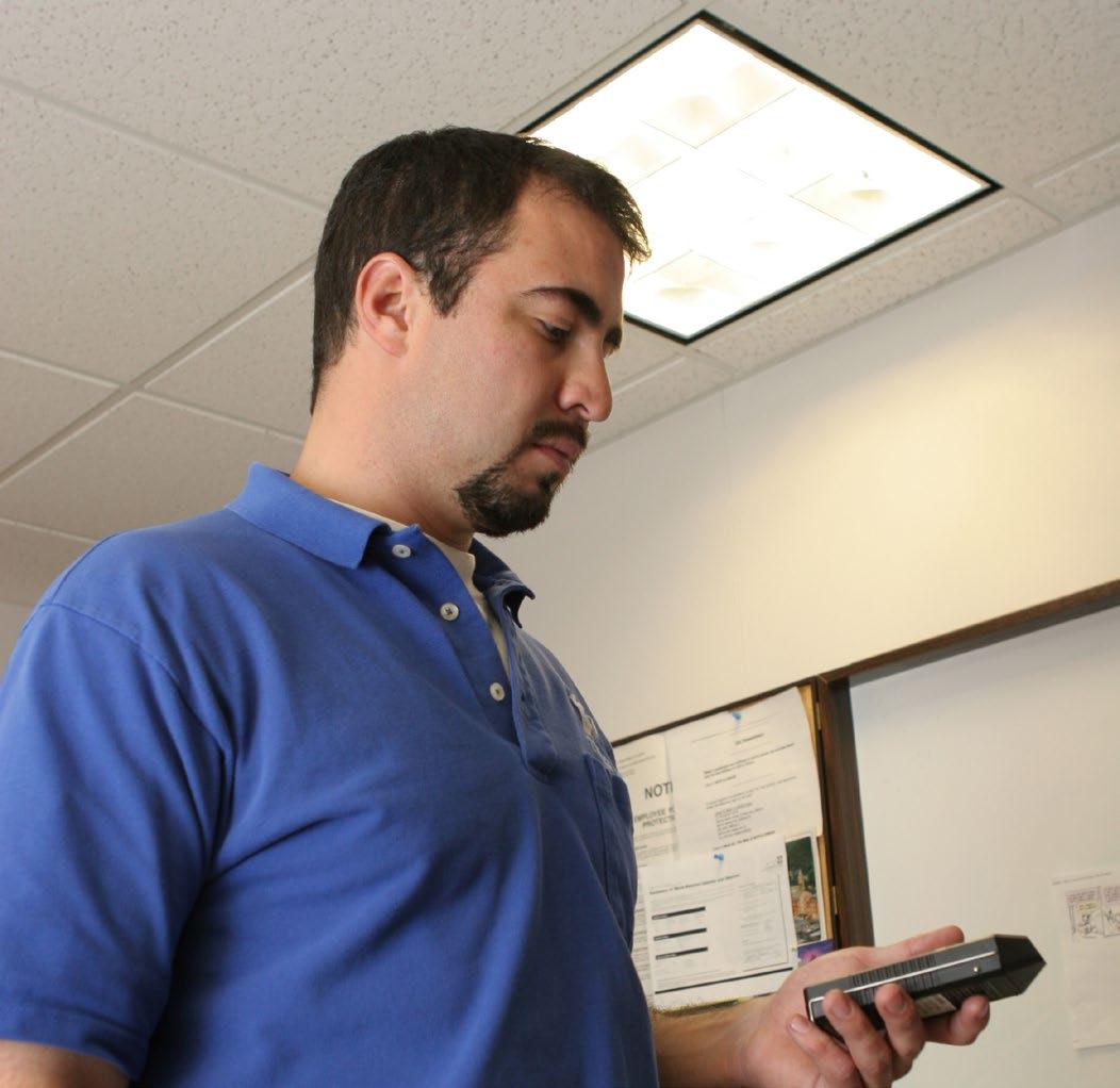
Light meters are handheld devices that measure the amount of light at a specific spot. By positioning the light meter on the work plane, you can determine the light density at that spot in footcandles (fc). This allows you to not only find out the amount of light (footcandles), but also the ability of room surfaces (such as walls, ceilings and flooring) to reflect light. The meter should be cosine-corrected and color-corrected, and should be calibrated periodically.
Before taking any measurements from a system in which new fluorescent lamps have just been installed, allow 100 hours of operating time for the lamps to stabilize. To get a true reading, no outdoor light can be allowed to enter the area. Since most lighting management operations happen after normal work hours, this may not be a problem. The procedure for measuring the amount of light in a space is shown below:
1. Expose the light meter’s sensor to the system’s light for about 15 minutes. This allows the meter to stabilize.
2. If the fluorescent lamps are just being turned on, leave them on for at least 10 minutes to allow them to stabilize.
FIGURE 2-5
3. Take the meter reading (horizontal tasks). The workstations should be on a horizontal plane (workplane). To gain a horizontal footcandle reading, lay the meter down flat on its back, with the sensor facing the ceiling. Be careful not to cast a shadow over or near the meter so as to avoid distorting the reading. Stand back from the meter when taking the actual readings to avoid blocking light and/or reflecting light onto the meter.
4. Take the meter reading (vertical tasks). Vertical tasks include warehouse racks and vertical merchandise displays in stores. Position the light meter on its base, with the sensor facing the room, and take the reading. Again, don’t let any shadows or reflected glare hit the meter or you’ll distort the reading.
5. Take the meter reading (room surface reflectance). Reflectance is the ability of the room’s surfaces, such as its walls, ceiling and floor, to reflect light. Knowing reflectances will help you by revealing how much room surface dirt and the surfaces’ colors are absorbing light instead of reflecting it to where people need it. To measure reflectance, get a footcandle reading holding the meter flat against the wall, with the sensor facing out into the work area, and note the reading. Then hold the meter between one and two feet from the wall, with the sensor facing the wall, and get another reading. Divide the second reading by the first reading to obtain a reflectance value for the surface:
Second Reading ÷ First Reading = Reflectance (%). To test the accuracy of your reading, you can use a white test card that has a known reflectance of 90%. Hold the test card against the wall and perform your test. If your results aren’t near 90%, the meter needs to be calibrated.
21 CHAPTER 2: PLANNED LIGHTING MANAGEMENT
Typically, an average light level reading for the entire work area is performed before cleaning and relamping and then after, using a light meter. Courtesy of Colorado Lighting, Inc.
CHAPTER
PLANNED LIGHTING MANAGEMENT
6. If outdoor light can’t be prevented from entering the room, take one reading with the lights on, then turn the lights off and quickly take another reading. The difference between the readings (reading with lights on minus reading without) is the light level produced only by the lighting system.
Be sure to measure light levels at a variety of workplane locations, including specific task locations and randomly throughout the room, between luminaires and in corners. Be sure to record the locations of readings for the baseline case so the procedure can be repeated after the project is complete. Adhesive labels can be used to mark measurement locations and corresponding values.
YOU’RE READY
Congratulations. If you score well on the Planned Maintenance Quiz, consider yourself well on your way to becoming a lighting management expert. Now you’re ready to learn about luminaires.
22
2:
PLANNED MAINTENANCE QUIZ
Check your understanding of this chapter’s material by completing these multiple-choice questions. The answers are on Page 82.
1. Which of the following is NOT a direct result of luminaire cleaning?
a) Helps maintain the luminaire’s intended light distribution
b) Increases reflectance of interior luminaire surfaces
c) Reduces maintenance costs
d) Enables lenses to transmit more light
2. Which of the following is typically a primary benefit of luminaire cleaning?
a) Improved safety
b) Improved visual appearance of space c) Raises average light levels d) All of the above
3. 3. Group relamping is defined as _____.
a) The practice of replacing all lamps in a lighting system after 50% of them have failed
b) The practice of replacing all lamps in a lighting system at scheduled intervals rather than individually as they fail
c) The practice of replacing all failed lamps in a lighting system in batches instead of individually as they fail d) None of the above
4. In the case of metal halide lamps, group relamping can also be useful to _____.
a) Prevent “cycling” which can occur at end of life
b) Minimize color shift and possibility of non-passive failure at end of life
c) Increase luminaire interior surface reflectances d) None of the above
5. In the case of high pressure sodium lamps, group relamping can also be useful to _____.
a) Prevent “cycling” which can occur at end of life b) Minimize color shift and possibility of non-passive failure at end of life
c) Increase luminaire interior surface reflectances d) None of the above
6. The fundamental economic principle behind luminaire cleaning is_____.
a) It’s cheaper to clean a luminaire than to continue operating a dirty one, in which the cost of wasted light has become higher than the cost to clean it b) It’s generally cheaper to clean all luminaires at once rather than individually as they get dirty c) It generally produces a return on investment of 33%, which is the typical minimum corporate hurdle rate.
d) None of the above
7. The fundamental economic principle behind group relamping is _____.
a) It’s cheaper to replace all lamps in a luminaire rather than continue operating a luminaire with some lamps operating and others having failed b) It’s generally cheaper to replace all lamps at once rather than individually as they fail c) It generally produces a return on investment of 33%, which is the typical minimum corporate hurdle rate. d) None of the above
8. The two primary variables in determining at what point group relamping makes economic sense are _____ and _____.
a) Wattage; number of lamps b) Wattage; mounting height of luminaires c) Number of luminaires; cost to group relamp each luminaire d) Total cost to group relamp one lamp; total cost to spot relamp one lamp
9. Which of the following is NOT an element of planning a maintenance operation?
a) Finding out where in the building the maintenance will be performed b) Finding out how luminaires will be accessed c) Finding out furniture tolerances, which will determine the weight of maintenance equipment that can be placed on furniture d) Finding out how the space is used, in particular whether the space will be occupied when maintenance operations are scheduled
10. How do disconnecting hangers work?
a) Grips lamps mechanically or through air suction b) Platform is raised or lowered manually or electrically c) Mobile platform that can be driven to the luminaire d) Access luminaires by lowering the luminaire to the technician
11. Which of the following cleaning materials and methods works best for cleaning aluminum?
a) Antistatic compounds; vacuuming is most effective for drying b) Detergents applied with a soft, damp rag c) Some strong cleaners, alcohol and abrasive cleaners d) Very mild soaps and cleaners followed by thorough rinse of clean water
23
MANAGEMENT
CHAPTER 2: PLANNED LIGHTING
CHAPTER
PLANNED LIGHTING MANAGEMENT
12. Lighting managers must be able to measure light levels in a room to _____.
a) Demonstrate to customers the benefits of luminaire cleaning b) Plan upgrades to energy-efficient lighting systems c) (a) and (b) d) None of the above
13. Light meters allow lighting managers to _____.
a) Measure the amount of light in a particular place in a room b) Determine the average amount of light throughout a room c) Determine the ability of room surfaces to reflect light d) All of the above
14. When using a light meter to measure horizontal workplane light levels in a room lighted with fluorescent lamps, which of the following should NOT be done?
a) Leave the lamps on for at least 10 minutes to allow them to stabilize
b) Position the light meter vertically on its base, with the sensor facing the room, and take the reading c) Expose the light meter’s sensor to the system’s light for about 15 minutes to allow the meter to stabilize d) All of the above
24
2:
CHAPTER 3: LUMINAIRES
A PRIMARY TOOL
A light fixture, also called by its technical name, luminaire, is a complete lighting unit that produces and distributes light to fulfill the design goals for the lighted space. The lamp produces light; the luminaire houses the lamp and distributes the light in a controlled manner.
Where the light goes—up, down—and how it’s distributed— reflected, diffused, refracted—depends on the luminaire’s optical system.
There are two important things we have to know about luminaires. First is to be able to properly identify them. Second is how they distribute light.
Once we know what types of luminaires there are and how they distribute light, we can then move on to designing lighting systems using them to meet our lighting goals for the building or building space.
CLASSIFICATIONS
Luminaies are typically classified according to light source, application, function, general design, layout/location, light distribution characteristics and mounting method.
Light Source
A luminaire can be described according to its predominant light source; therefore, a given luminaire could be called an incandescent luminaire, fluorescent, high-intensity discharge (HID), metal halide, etc.
Application
Luminaires can be designated as indoor, outdoor, industrial, commercial, residential, parking lot, wharf, wet location, hazardous location, etc.
Function
A luminaire can be described by general function (architectural or decorative) or by specific function (ambient lighting, downlighting, accent lighting, wet location, hazardous location, etc.).
General Design
Luminaires can be designated as individual units, in continuous rows, as floating panels or in a luminous or louveralled ceiling.
Layout/Location
Luminaires can be classified as general, localized general, localized and task.

General lighting provides a generally uniform light level on the workplane throughout the lighted space. In review, the workplane is an invisible plane in the space defining the primary task area. In a typical office, the workplane would be the desktop, about 2.5 feet off the floor.
Localized general lighting is similar but is tailored more to the location of tasks in the lighted space.
Localized lighting, also called supplemental lighting, is used to provide light to a specific area. Some localized lighting is called task lighting, which delivers light tailored for a specific task. A typical task light would be a desk lamp.
Light Distribution Characteristics
There are multiple ways to classify luminaires according to how they distribute light.
Luminaires can be categorized as being a point source, linear source or area source. Point sources are small lamps, often featuring a clear outer glass bulb revealing the arc tube or bare incandescent filament, used to produce dramatic highlights and pronounced shadows. Linear sources, such as tubular fluorescent lamps, emit diffuse output from the surface of the lamp, softening shadows. Area sources are not lamps but instead large surfaces that emit diffuse light, such as ceilings reflecting illumination from an indirect luminaire, or the surface of a luminous bowl pendant luminaire.
FIGURE 3-1
System for classifying luminaires according to how they distribute light. Note, however, that not all luminaire manufacturers follow this system strictly, and instead define their luminaires more generally in their descriptions.
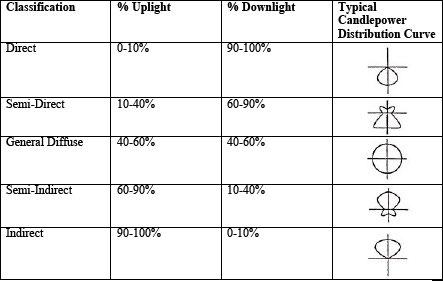
25 CHAPTER 3: LUMINAIRES
CHAPTER 3: LUMINAIRES
Luminaires may be categorized as having a symmetric or asymmetric distribution.
They can also be categorized by width of beam of light upon striking the workplane (wide, narrow, medium, etc.).
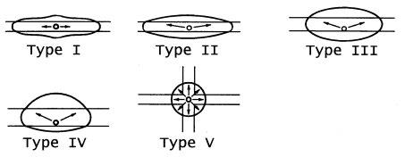
They can be classified according to the light distribution, which designates luminaires based on the percent of light output above and below horizontal—direct, indirect, etc. (see Figure 3-1).
Type V. Symmetrical, a circular pattern of light.
Type VS or VQ. Symmetrical square pattern of light.
A shielded luminaire provides greater control of light distribution by trimming the distribution pattern. A given luminaire, for example, may be available with louvers and shields, which enable the distribution pattern to be trimmed so that the pattern is more controlled.
Cut-off refers to the proportion of light output of a luminaire being distributed at 80° and 90° above nadir. Again, nadir is 0°, a line pointing straight downward from the light source.
REMEMBER
You may see a difference in the way luminaires are described by organizations such as the Illuminating Engineering Society of North America (IESNA), which creates accepted guidelines, and manufacturers, who may describe their products differently to either differentiate them or appeal to the broadest common denominator of construction professional. While IESNA may be guilty in some cases of appearing to make lighting too sophisticated (complex), manufacturers may sometimes be guilty of oversimplifying. As a lighting manager, you can use either vocabulary, as long as you can speak both languages and know the difference.
FIGURE 3-2
Plan views (looking down at a luminaire near a roadway) of light distributions for basic types of conventional outdoor luminaires. Courtesy of State of Texas.
Non-Cutoff. No light output limitations in any zone.
Semi-Cutoff. Light output at 90° above nadir is less than 5% of rated light output. Light output at 80° is less than 20% of rated light output.
Cutoff. Light output at 90° above nadir is less than 2.5% of rated light output. Light output at 80° is less than 10% of rated light output.
Full Cutoff. Light output at 90° above nadir is 0% of rated light output. Light output at 80° is less than 10% of rated light output.
Luminaires featuring a choice of cut-off optics include floodlights, building-mounted cut-off luminaires, controlled post-top luminaires and low-mounted site lighting.
FIGURE 3-3
The candlepower of luminaires designated as full cutoff, cutoff and semi-cutoff is limited at angles of 90 and 80 degrees from the nadir, 0 degrees, an imaginary line pointing straight downward from the light source. Courtesy of State of Texas.
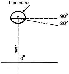
Outdoor Lighting
Outdoor luminaires are further classified according to a system developed by the Illuminating Engineering Society of North America (IESNA), which includes distribution and cut-off.
Figure 3-2 shows plan views of light distribution patterns for the basic types of conventional luminaires, along with designations Type I through Type V.
Type I. Narrow symmetric distribution; highest intensity is at nadir. Nadir is 0°, a line pointing straight downward from the light source.
Type II. Wider distribution; highest intensity is between 10 and 20° from nadir.
Type III. Wide distribution; highest intensity is between 25 and 35° from nadir.
Type IV. Widest distribution.
Shielded and cutoff luminaires are growing in importance due to “light pollution” concerns, such as light trespass, skyglow and glare. Glare is a traditional outdoor lighting design concern, but numerous states and municipalities have begun adopting laws that try to regulate light trespass and skyglow, making these issues more important.
Light trespass occurs when light produced by a lighting system spills onto neighboring property, creating a nuisance.
Skyglow occurs when light is distributed into the night sky, obscuring a view of the stars.
26
REMEMBER
Full cutoff and cutoff luminaires are becoming more popular in outdoor lighting designs because of glare, skyglow and light trespass concerns. Many areas of the country now have laws that require solutions for light pollution. While these luminaires can reduce light pollution, more luminaires may be required to sufficiently light the area.
same language to increase understanding and avoid errors.
“The track lighting [mounting method] uses 10 metal halide [light source] accents [function].”
“It’s an electronic T8 [light source/ballast] lighting system.”
“It’s a typical outdoor [location] pole-mounted [mounting method] full cutoff [distribution] high pressure sodium [light source] luminaire.”
“The indoor [location] general lighting [layout/location] is made up of 40 suspended [mounting method] fluorescent [light source] direct-indirect [distribution] luminaires in continuous rows [general design].”
OPTICAL SYSTEMS
We now know how to identify popular luminaires based on a number of ways in which they are classified. Every luminaire has an optical system, which receives the light emitted from the lamp and distributes it in a controlled pattern.
How to Evaluate Optical Systems
Optical systems can be judged in four ways:
How efficient is the luminaire? How much light is produced by the lamp that escapes the luminaire instead of being trapped inside and wasted? Higher-quality optical systems are very efficient and allow the maximum amount of light to exit the luminaire, where it can be used.
Mounting Method (Indoor Luminaires)
Luminaires can be designated according to how they are mounted in the lighted space:
• Recessed (luminaire’s edge or open face is mounted at the ceiling line)
• Regressed (luminaire’s edge or open face is mounted above the ceiling line)
• Surface-mounted (mounted on the ceiling or wall)
• Pendant-mounted or suspended (suspended from the ceiling with supports)
• Track (mounted on a metal strip)
• Architectural/Built-in (example: luminaire built into a shelf)
• Portable (any free-standing and portable luminaire)
Mounting Method (Outdoor Luminaires)
Outdoor luminaires can be designated according to how they are mounted in the lighted space:
• Pole-mounted
• Surface/Wall-mounted
• Bollard (a short post used to provide lighting for walkways)
• Burial/In-Ground
Examples: The following are common expressions you may hear as a lighting manager based on the above nomenclature. Using these classifications, a significant amount of information can be conveyed in a single sentence. While lighting people appear to speak a different language, it’s essential that they all speak the
How much control does it provide over light distribution? If we want all of the light coming out of the luminaire going to a specific area, does it go to that area and nowhere else? Higher-quality optical systems tightly control light distribution.
How well does it handle heat? Heat is the primary enemy of lamps and ballasts, as excessive heat around these components can shorten component life and reduce light output and system efficiency.
How easy is it to maintain? Different materials and finishes dictate different cleaning methods.
Typical Optical Systems
The primary methods of controlling light from a bare light source via a luminaire are reflection, transmission and refraction. Other methods include polarization, interference and absorption.
Reflection: Reflection, the most common form of controlling light, occurs when light rays impact and are then reflected from a
FIGURE 3-4
Reflection. Light rays strike a surface and are reflected off of it. The angle of incidence is equal to the angle of reflection. (The horizontal line is the optical system surface; the arrows show the path of a light ray.)
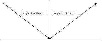
27
LUMINAIRE TYPE PERCENT OF TOTAL CANDLEPOWER AT 90° FROM NADIR (HORIZONTAL) PERCENT OF TOTAL CANDLEPOWER AT 80° FROM NADIR Full-cutoff 0% ≤10% Cutoff ≤
≤10%
≤
≤
CHAPTER 3: LUMINAIRES
2.5%
Semi-cutoff
5%
20% Non-cutoff No limitation in either zone. Table 3-1. Candlepower cutoff requirements for different luminaire types.
CHAPTER 3: LUMINAIRES
FIGURE 3-5
Spread reflection. Light is reflected into a cone of light rays. (The horizontal line is the optical system surface; the arrows show the path of a light ray.)
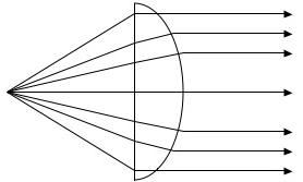

FIGURE 3-7
Direct transmission. Light passes through a material with no significant change in its direction. (The horizontal line is the optical system surface; the arrows show the path of a light ray.)


FIGURE 3-6
Diffuse reflection. Light rays are reflected to produce a variety of angles. (The horizontal line is the optical system surface; the arrows show the path of a light ray.)
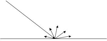
FIGURE 3-8
Diffuse transmission results from a dense diffuser causing incident light rays to be widely spread. (The horizontal line is the optical system surface; the arrows show the path of a light ray.)
surface. In other words, light hits the surface (incident rays), and is then reflected off of the surface (reflected rays). Types of reflection include specular, diffuse, spread and selective.
Specular reflection is when light is reflected from a highly polished surface such as smooth polished metal, producing a consistent angle.
Spread reflection is when light is reflected into a cone of light rays from surfaces such as corrugated or etched metal, plastic or glass.
Diffuse reflection is when light is reflected from a rough surface, producing a variety of angles depending on how the light impacts each tiny part of the rough surface. Diffuse reflection is typically used to minimize glare, hot spots and shadows.
Selective reflection is when a colored surface is used so that only certain color wavelengths or reflected as opposed to absorbed or transmitted.
How the reflecting surface is shaped determines how the beam is reflected. The most popular shapes for such surfaces include circular, parabolic, ellipsoidal and combination.
Transmission: Transmission occurs when light rays are passed through a material. The types of transmission include direct, diffuse, spread and selective.
Direct transmission is when light rays go through the material with no change to their direction or color. Example: Clear plate glass.
Diffuse transmission is when light rays are widely spread, useful when we want to obscure the light source and produce a uniform appearance of light on the transmitting surface. Example: Inside-
FIGURE 3-9
Refraction occurs when light rays pass through one medium into another at a different intensity. This phenomenon is why a straw appears to bend at the point where it enters the water in a drinking glass.
frosted glass.
Spread transmission is when the maximum intensity of light rays passed through with little change in direction, producing a glow on the transmitting surface and a sense of sparkle.
Selective transmission is when selected color wavelengths are allowed to pass through the material. Example: Colored glass.
Refraction: Refraction, used in prismatic lenses in fluorescent luminaires, floodlighting and streetlighting, occurs when light rays pass through one medium to another obliquely and experience a change in direction and speed.
LUMINAIRE EFFICIENCY
The luminaire’s efficiency is the ratio of light output emitted by the luminaire to the light output emitted by its lamps. Another way of
28
looking at it: Luminaire efficiency is the percentage of light output produced by the lamps that are in turn emitted by the luminaire.
Not all light produced by the lamps will exit the luminaire; some will remain trapped inside and dissipated as heat. The luminaire’s physical characteristics will affect how much light will leave the luminaire and how much will be directed at the workplane.
Luminaire efficiency is important because while you can have a very efficient lamp-ballast system, if the luminaire itself is not efficient, then the lighting system overall isn’t either. Factors that affect the efficiency of the luminaire include its shape, the reflectance of its materials, how many lamps are inside the luminaire (and how close they are to each other), and whether shielding material such as a lens or louver is used to soften or scatter the light.
Coefficient of Utilization (CU): The CU value is a metric that allows us to look at luminaire efficiency in the context of a room. Since all room surfaces are potential reflectors of light, the room itself acts an extension of the lighting system. A given luminaire may emit some of its light directly at the workplane and some at a nearby wall. The wall absorbs some of the light and reflects the rest, some of which in turn reaches the workplane.
CU therefore allows us to compare luminaire efficiencies in a given environment. It shows the percentage of light output produced by the lamps that reaches the workplane after light is lost due to the luminaire’s efficiency at transmitting light, the room proportions, and the ability of room surfaces to reflect light.
FIGURE 3-10
Key light creates drama.
REMEMBER
Luminaire efficiency is the percentage of light emitted by the lamps that actually exits the luminaire. Coefficiency of utilization shows the percentage of light reaching the workplane for a luminaire in a given room, taking into account the room itself as an extension of the lighting system.
FIGURE 3-11
Fill light softens shadows and adds depth.

HOW LUMINAIRES ARE USED TO CREATE EFFECTS
As a lighting manager, your job will be to make sure that the lighting system performs its best for the lowest ongoing cost. To ensure the lighting system performs its best, you should understand the intent that went behind its design. On the job, you will see many types of luminaires, lighting schemes and design approaches, and it always pays to know what the designer was thinking.
Lighting can be used for a myriad of purposes, but as an introduction, several basic design approaches, used to produce a wide range of effects, are shown below.
Key Light
When we shine a light on an object from a single point source of light it is called key light; it highlights contours on the object and creates shadows; the exact effect depends on the angle of the beam of light.
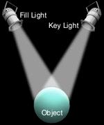
Fill Light
While this scene effects drama, for our purposes we will assume we need fill light. It can either be directional or diffused. In our example, we could shine a directional light on the object from the opposite direction of the key light, softening or eliminating shadows depending on the strength of the fill light relative to the strength of the key light. We could also place fill light sources behind the object to light the entire room evenly. In Figure 3-11, we see the keylight supplemented by a single fill light.
Silhouetting
Suppose we wanted to emphasize the shape of the object as a silhouette. In this event, we would soften or even eliminate the key light and directional fill light, and instead provide only fill light, either intense or diffused, depending on the clarity of the silhouette and
FIGURE 3-12
Silhouetting.
29
CHAPTER 3: LUMINAIRES
the drama we want to produce.
Uplighting
Suppose we wanted to uplight the object. The effect of uplighting is either very desirable or very undesirable because it is unusual. Effects range from intimate to eerie. A lot of landscape lighting includes uplighting to accentuate bushes and trees.
Sparkle And Glitter Effects
To add an atmosphere of elegance, we could add little lighting points of interest in the form of sparkle or glitter. This effect can be produced by either producing sharp reflections on specular surfaces in the room (sparkle), such as silverware in a restaurant, or by making the light source itself a source of interest (glitter) such as with a chandelier. Beware of glare in such cases.
Grazing And Washing Surfaces

On walls or on the surface of an object, we can change the way light impacts them so that we can produce different effects. Suppose we have a brick wall with a rough texture that we want to emphasize. We could graze the surface with light, meaning the light would strike the surface at a sharp angle. In this case, the light source would be mounted close to the wall. Now suppose the wall is smoother, and we want to emphasize that smoothness.
FIGURE 3-13
Grazing means striking a vertical surface at a sharp angle.
We could wash the surface with light, meaning the light would strike the surface at a wider angle.
YOU’RE READY
Congratulations. If you score well on the Luminaires Quiz, consider yourself well on your way to becoming a lighting expert. Now you’re ready to learn about emergency lighting.
FIGURE 3-14
Washing means striking a vertical surface at a wide angle.
30
CHAPTER 3: LUMINAIRES
LUMINAIRES QUIZ
Check your understanding of this chapter’s material by completing these multiple-choice questions. The answers are on Page 82.
1. Which of the following would be a luminaire classified according to application?
a) Fluorescent b) Parking lot c) Downlighting d) Localized lighting
2. Which of the following would be a luminaire classified according to function?
a) Fluorescent b) Parking lot c) Downlighting d) Localized lighting
3. Which of the following would be a luminaire classified according to light source?
a) Fluorescent b) Parking lot c) Downlighting d) Localized lighting
4. Which of the following is NOT a way to classify a luminaire according to how it distributes light?
a) Symmetric or asymmetric b) Width of beam of light striking the workplane (wide, narrow, etc.) c) Accent lighting d) CIE system (direct, semi-direct, etc.)
5. A semi-indirect luminaire emits _______% of its light upward and _______% of its light downward.
a) 0-10; 90-100 b) 40-60; 40-60 c) 60-90; 10-40 d) 90-100; 0-10
6. Why are cutoff and full cutoff outdoor luminaires becoming more popular?
a) They reduce the impact of light pollution b) They reduce glare c) (a) and (b) d) None of the above
7. Which is the most common method of controlling light using a luminaire?
a) Refraction b) Diffusion c) Reflection d) Transmission
8. Luminaire A has a lighting system that produces 5000 lumens, draws 100 watts, and has a luminaire efficiency of 70%. Luminaire B has a lighting system that produces 6000 lumens, draws 150 watts, and has a luminaire efficiency of 75%. Which luminaire is more efficient in terms of lumens emitted per watt consumed?
a) Luminaire A (40 lumens per watt vs. 45 lumens per watt for Luminaire B) b) Luminaire A (35 lumens per watt vs. 30 lumens per watt for Luminaire B) c) Luminaire B (40 lumens per watt vs. 45 lumens per watt for Luminaire A) d) Luminaire B (30 lumens per watt vs. 35 lumens per watt for Luminaire A)
9.
What is wall washing?
a) Light from the light source strikes the wall at a wider angle, “washing out” details and emphasizing the wall’s smoothness b) Light from the light source strikes the wall at a sharp angle, creating more shadowing and emphasizing the wall’s rough texture
c) Light from the light source strikes the wall from behind, creating a silhouette d) None of the above
31 CHAPTER 3: LUMINAIRES
LIGHTING
CHAPTER 4: EMERGENCY LIGHTING
LIGHT SAVES LIVES
The purpose of emergency lighting is to help people get out of a building safely during an emergency in which the building’s primary power supply is cut off and the lighting fails. Specifically, it will identify the routes leading to the exits, and provide a minimum amount of light along the routes for people to leave the building in an orderly and safe manner. The overall goal is to save lives during any situation that requires evacuation, whether it’s a fire, earthquake, terrorist attack, blackout or other emergency.
Lighting managers often wear two hats, a “doer hat” and a “thinker hat.” They must provide services that are required, while consulting with their customer on beneficial service offering or options that could be done. Regarding emergency lighting, lighting managers must perform routine testing to ensure that their customers’ emergency lighting continues to perform to code requirements and their safety goals. They can also advise their clients on how to save money by upgrading obsolete emergency lighting systems to systems that save energy and provide longer service life.
LIGHT IS THE LAW
Emergency lighting has been mandated in commercial buildings since the 1940s. Rules governing how emergency lighting should perform can be found in state and local laws and building codes.
Codes can vary from one state or municipality to the next, but most are based on the National Electrical Code, NFPA 70, Article 700; the Life Safety Code, NFPA 101, “Code for Safety to Life from Fire in Buildings and Structures,” Sections 7-8 through 7-10; and the Occupational Safety and Health Act (OSHA), which offers general guidelines.
Key Requirements of the Life Safety Code:
• No part of an exit route should be more than 100 ft. from the nearest visible exit sign.
• In the event of a power failure, the transfer to the emergency lighting system must be automatic (within 10 seconds).
• Emergency lighting must be provided throughout the path of egress, providing an average of one footcandle along the path, with changes in direction clearly marked, and operate for a minimum of 90 minutes. In some areas, at least one footcandle is required all along the path, not an average of one footcandle.
• After installation, all emergency lighting equipment must be tested periodically.
INDOOR VS. OUTDOOR
Most emergency lighting is found inside the building. But in a growing number of states such as Ohio, Pennsylvania and California, emergency lighting is being required by code to be installed in outdoor areas as well.
NFPA 101, Life Safety Code 2000 (7.8.1.1), adopted by most states, requires: “Illumination of means of egress shall be provided in accordance with Section 7.8 for every building and structure
REMEMBER
Local codes may vary, but the Life Safety Code, on which most codes are based, requires that in the event of a power failure, the emergency lighting will activate within 10 seconds, and will light the entire path of egress for at least 90 minutes.
where required in Chapters 11 through 42. For the purposes of this requirement, exit access shall include only designated stairs, aisles, corridors, ramps, escalators, walkways and exit passageways leading to a public way.”
What this basically means: Required light levels will be mandated for designated buildings along the path of exit to a public way.
The question on some people’s minds: What does “public way” mean?
Traditionally, it meant the path to the building exit. But since the mid 90s, a growing number of entities having the authority to interpret local codes have begun interpreting “public way” to mean a street or alley. In some states, this interpretation is now written into the code. This means that not only must the path of egress be lighted inside the building, but also outside the building, which could include the area around the building exit and also a path in the grounds leading to a street or alley.
The 2003 International Building Code provides additional information. It requires access to a public way, and when a public way cannot be provided, a safe dispersal area will be provided. This area must be of certain size, on the property but at least 50 feet from the building, and have a safe and unobstructed path of travel from the building to it.
Emergency luminaires used outdoors are in some cases similar to those used indoors, but with features that enable them to work well in outside conditions. Features include vandal-resistant, rugged construction and the ability to start and operate in extreme temperatures and wet or damp locations.
REMEMBER
Traditionally, emergency lighting was required only indoors. In recent years, however, a growing number of states are interpreting the Code to require emergency lighting in some outdoor areas as well. It all depends on how “public way” is interpreted.
32
CHAPTER 4: EMERGENCY
EXIT AND DIRECTIONAL SIGNS
Exit and directional signs identify the route to the exit, while strategically placed emergency lighting luminaires or units light the way. Some units combine the functionality of an exit sign and an emergency luminaire.


Exit Signs
Exit signs are luminaires that serve as a beacon during emergencies, identifying the path to the building exit and the exit itself. They are different from directional luminaires in that they don’t illuminate anything; instead, they glow bright enough so that they can be read in darkness and ideally in smoky conditions. Model codes require that all exits and accesses to exits be marked with readily visible signs.
Exit signs are fed from the power line and are usually also connected to the central emergency power back-up system. Some contain a backup lamp connected to a battery (required in new installations).
Exit signs are generally red but some may be green. Which ever the case, the Code required all exit signs within a building be of the same color. California also requires a second sign to be installed at floor level, based on the logic that during a fire, people may be crawling out of the building due to smoke.
Lamps: The standard light source for exit signs for decades was the incandescent lamp. The vast majority of the estimated 100+ million exit signs currently installed in the U.S. still use incandescent lamps, consuming 30-35 billion kWh of energy.
REMEMBER
Exit signs indicate the route to the exit, while emergency luminaires light the path to the exit.
In new signs being sold, however, incandescent lamps have been virtually eliminated. Manufacturers estimate that 85-95% of all new exit signs currently sold in the U.S. are light-emitting diode (LED), with 2.5-5% compact fluorescent and 2.5-5% incandescent. The reason is that these other light sources, particularly LEDs, are much more efficient than incandescent lamps, while lasting longer, saving money on the electric bill and on ongoing maintenance.
LEDs are solid-state devices that produce light differently than incandescent and fluorescent sources. They are highly efficient and produce a high quality, color and strength of light, particularly colored light like red, amber or green. They can also last 10-25 years. They currently dominate the exit sign market, are estimated to have taken about 30% of the traffic signal market, and are now competitive with incandescent lamps in a broad range of commercial applications, from downlights to task and accent lighting.
Other light sources are trying to make inroads against LEDs in exit signs, such as cold cathode, electroluminescent, tritium and photoluminescent.
REMEMBER
Most new exit signs use LEDs as the light source, which are much more efficient than the traditional incandescent lamps used in exit signs. Many exit signs still use incandescent lamps, however—each of them an upgrade opportunity.
FIGURE 4-1
FIGURE 4-2
Tritium exit signs feature tritium-filled gas tubes, which require no electrical input. Courtesy of Lithonia.
Types of Exit Sign Luminaires: There are basically four types of exit sign luminaires available: panel, stencil, edge-lit and matrix.
In a panel sign, the face consists of a single translucent panel. Both the letters and the background are lighted. Example: Exit sign with red letters and a white background. The light source in this type of sign must be white so that the lettering appears red and the background
33
LED exit signs. Courtesy of Highlites.
CHAPTER 4: EMERGENCY LIGHTING
Table 4-1.
Comparison of exit sign alternatives. Source: Platts.
LIGHT SOURCE WATTAGE LIFE APPROXIMATE Wh/yr/sign ANNUAL ENERGY COST
Incandescent 24-40 2-8 months 210-350 $21.00-$35.00
LEDs
< 1-5 10+ years < 9-44 < $0.90-$4.40
Compact Fluorescent 10-24 1-2 years 87-210 $8.70-$21.00
Electroluminescent < 1 10+ years < 9 < $.90
Photolumniescent
0 10+ years 0 $0.00
Cold cathode 5 10 years 44 $4.40
appears white, providing maximum contrast for visibility. In a stencil sign, the background is opaque while only the letters are lighted. Any light source can be used in a stencil sign.
In an edge-lit sign, the light is distributed from the edge of the sign, which is a transparent plate that has the letters etched in or attached to its surface. The light passing through the plate illuminates the lettering.
In a matrix sign, used almost exclusively with LEDs, individual LEDs form the letters against an opaque background.
FIGURE 4-3
Edge-lit exit sign. Courtesy of Lithonia.
Backup Power Supplies: Incandescent exit signs are ideal candidates for upgrades to more-efficient lighting to reduce energy and maintenance costs for building owners. When upgrading an exit sign, the lighting manager must take into account the current power supply. The selected upgrade luminaire must be compatible with backup power supply.
When using a battery backup (individual inverter) system, exit signs are powered by individual batteries during a power outage.
When using a battery backup (central inverter) system, a group of exit signs are powered by a central inverter system.
When using a battery backup (DC system), a dual circuit supplies “normally on” AC power circuit to operate two line-voltage AC lamps and “normally off” DC battery power to operate two lowvoltage DC lamps.
When using a central standby generator, typically used in large buildings, a backup power generator provides line voltage to the emergency lighting system.
REMEMBER
Backup power supplies may either be a battery or a central standby generator.
Emergency lighting luminaires aren’t as noticeable as exit signs. Exit signs, in fact, are only successful if they are highly visible during an emergency. Emergency luminaires aren’t meant to be seen, they are meant to see with. Their job is to light the path

34
Emergency Lighting Luminaires
CHAPTER 4: EMERGENCY LIGHTING
Table 4-2.
Compatibility of exit sign sources and types of signs. SIGN TYPE INCANDESCENT COMPACT FLUORESCENT
FIGURE 4-4
LED retrofit kits like this one can convert virtually any stencil-face incandescent exit to an energy-efficient LED sign, reducing energy costs. Courtesy of Lithonia.
FIGURE 4-5
Emergency lighting unit. Courtesy of Lithonia.
of egress during an emergency. As a result, they are typically designed to blend into the architecture, or emergency lighting functionality is integrated with existing luminaires.
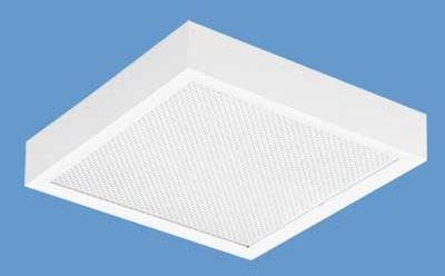
The basic types of emergency lighting systems are wall-mounted, remote-mounted, fluorescent and HID standby. All are operated by a battery power source within the emergency lighting unit. When the normally power supply is interrupted, the lamps are turned on. The battery keeps the lamps lighted for 90 minutes or longer.
Wall-Mounted: Literally scores of wall-mounted units are available. These units are essentially small cabinets with one or two low-voltage (4-, 6- or 12-volt) sealed-beam reflector incandescent or halogen (PAR36, PAR46 or MR16) lamps mounted on the top or sides on swivels. (MR16 lamps are growing in popularity for their beam control, while Xenon and Krypton lamps are growing in popularity due to their high efficiency, a 60-100% increase in
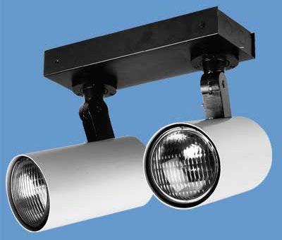
FIGURE 4-6
Unit designed to provide unobtrusive emergency lighting, available flushed, semi-recessed or recessed. Courtesy of Lithonia.
35
X X
X
X X
X X X
X
LIGHT EMITTING DIODE (LED) ELECTROLUMINESCENT Panel
Stencil
X
Edge-lit
Matrix
CHAPTER 4: EMERGENCY LIGHTING
CHAPTER 4: EMERGENCY LIGHTING
performance over incandescent lamps.) The swivels give the user the flexibility to turn the lamps to face wherever needed—usually the nearest exit or a potential hazard in the area.
The lamps are switched to a rechargeable battery power supply when the primary power supply is disrupted. The lamps are reconnected to the primary circuit when the power is restored.
The reflector lamps usually used in these units are available in a variety of light beam patterns, from narrow to wide. The appropriate pattern lamp depends on the needs of the application. When replacing a failed lamp, be sure to install one with the same lamp number to preserve the original beam pattern, and ensure compatibility with the batteries providing power to the lamp.
Figure 4-7
Wall-mounted industrial emergency lighting luminaire that is sealed and gasketed to guard against hose-down, dust and corrosive environments. Courtesy of Lithonia.
FIGURE 4-9
Outdoor emergency lighting luminaire, which features a durable housing, two Xenon lamps, nickel cadmium batteries, wet and cold weather operation, and self-diagnostics. Courtesy of Lithonia.
FIGURE 4-8
Wall-mounted outdoor emergency lighting luminaire. Courtesy of Invue Lighting.

Fluorescent Luminaires: Designated fluorescent or compact fluorescent luminaires in an installation can be fitted with a one-piece self-contained unit that looks like a ballast. It contains a battery, switching circuits and charging circuit. When the primary power supply is interrupted, it lights one lamp in the luminaire at reduced light output. When the power supply is restored, it switches back to the charging mode.
HID Standby Luminaires: HID lamps can take several minutes— sometimes as long as 10-15 minutes—to restart after they go out. An interruption as short as a fraction of a second in the power supply can extinguish an HID lamp.
HID luminaires are available with a built-in backup lamp that is lit when a temporary power interruption occurs. It provides light while the HID lamp cools down and restarts.
High-pressure sodium lamps are available that contain two arc tubes. When a voltage dip or a momentary power interruption occurs, the lighted arc tube goes out. When power is restored, the other “cool” arc tube illuminates, providing 3-5% of light output immediately and reaching full light output within two minutes.
Remote-Mounted: These are bracket assemblies or luminaires remotely located from the cabinet or battery. The brackets hold the PAR lamps and attach to a switch or junction box. The luminaires can be downlights containing the PAR lamps or recessed, lensed squares containing low-voltage incandescent lamps.
A current trend in lighting is to convert standard metal halide luminaires to T5HO fluorescent luminaires in high-bay applications, a concept with various advantages and disadvantages. One of the advantages is that it produces the opportunity to incorporate emergency lighting into the T5HO luminaires.
Batteries: Emergency lighting units often run on batteries because the primary power supply is assumed to be disrupted during emergency conditions, and a backup power supply can be expensive. The two major types of batteries are lead acid and nickel
36
FIGURE 4-10
Fluorescent emergency ballast for T5 and T5HO lamps. This ballast contains self-testing and self-diagnostic functionality, meaning it automatically conducts code-required testing (30-second monthly; 90-minute annual) and monitors its status on an ongoing basis.
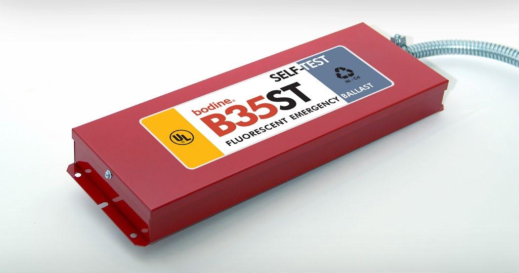
Courtesy of The Bodine Company.
FIGURE 4-11
Central AC system; this model can power up in as short as three milliseconds to provide emergency lighting power to a number of designated fluorescent luminaires. Courtesy of Highlites.
Table 4-3.
Average battery life. Heat and other conditions affect battery life. Battery life is defined as the point at which the battery goes dead and cannot be effectively recharged.
BATTERY TYPE BATTERY LIFE
Wet nickel cadmium 25 years
Sealed nickel cadmium 15 years
Wet lead acid 10 years
Cylindrical lead acid 8 years
MAINTENANCE
Since the lives of your customer and all building occupants depend on it, emergency lighting units must be maintained to ensure they’ll work when called upon. Testing and maintenance is required by the NFPA Life Safety Code. Testing can be performed manually (see below), or testing and diagnostic reporting can be automated using self-testing/diagnostic emergency lighting units, which have begun to grow in popularity since they became allowed by code.
To run a battery check, use the indicator lights and the test button. The test button removes the AC input power to the unit and basically simulates what would happen if the power line failed. The lights should come on. The lights should continue to burn brightly as long as the button is depressed. This will tell you that the battery is operational.
Annually, a 90-minute system check is required to ensure the battery has enough charge to perform this task. If it can’t, the battery should be replaced and the inverter and charging system should be tested for proper operation. After battery replacement, perform a systems check.
cadmium. Lead acid batteries may be wet cells, gelled electrolyte cells, or cylindrical pure lead cells. Nickel cadmium batteries may be wet cells or sealed cylindrical cells.
These battery types are rechargeable and must be recharged from time to time. Over time, all batteries leak small amounts of power and must be refilled periodically or else they may fail to light the lamps when they are needed in an emergency condition.
These battery types also eventually wear out because after each recharging the capacity of the battery to hold a charge diminishes. Thus, batteries will have to be replaced periodically to ensure continued operation of the emergency luminaires, per code.
To run a systems check, go through the following procedure, writing down any repair needs to be performed later, and results of our tests. This type of maintenance reveals whether the unit is working properly.
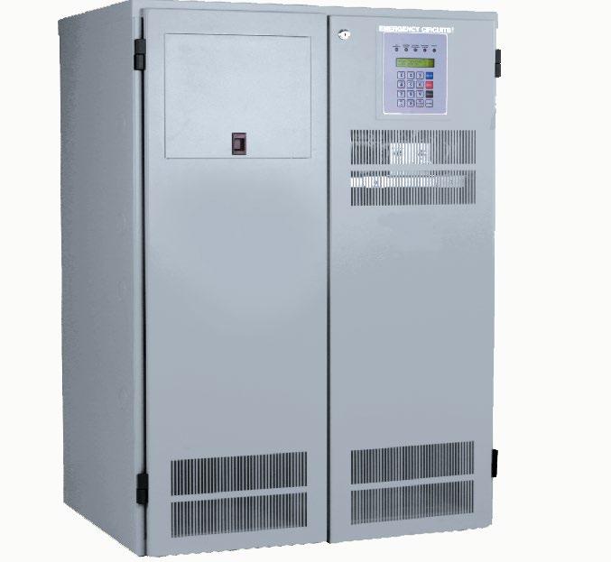
1. Check for physical damage to the outside of the unit.
2. Open the unit. Check the battery terminals for tightness and to make sure they’re clean. Tighten and clean as needed. Check the water level in the battery and refill if necessary. Check for physical damage to the battery.
3. Test battery voltage using a DC volt meter.
37
LIGHTING
CHAPTER 4: EMERGENCY
CHAPTER 4: EMERGENCY LIGHTING
Table 4-4. Optimal voltages for popular battery types.
4V n/a n/a 3.65V 3.75V
6V 5.3V 1.15V/cell 5.5V 5.65V
12V 10.05V 1.15V/cell 10.95V 11.3V
24V 21V 1.15V/cell 21.95V 22.6V
*Maintenance-free does not mean the system must not have to be maintained per the National Electrical Code. What this means is that you do not have to add distilled water to battery cells that are empty, as you do with wet cell batteries. Dry cell batteries are “maintenance free” because they do not have to have water added periodically. While dry cell batteries offer the convenience of not having to be refilled, they generally have shorter lives than wet cell batteries.
4. Remove AC power input by pressing the test button. The lights should come on. Hold the button down for five minutes. Compare voltages to the appropriate discharge figure in Table 4-4.
5. Turn the AC power back on by letting go of the button. The charger light should turn on brightly and the lamps should shut off. Within two hours, the charger light should dim.
6. Record the date and result of your test on an inspection label or other form to be kept on file as a permanent record.
YOU’RE READY
Congratulations. If you score well on the Emergency Lighting Quiz, consider yourself well on your way to becoming an emergency lighting expert. Now you’re ready take on the next chapter: Energy Management/Lighting Controls.
38
NOMINAL VOLTAGE WET CELL LEAD ACID WET CELL NICAD “MAINTENANCE FREE”* GEL CELL “MAINTENANCE FREE”* PURE LEAD
EMERGENCY LIGHTING QUIZ
Check your understanding of this chapter’s material by completing these multiple-choice questions. The answers are on Page 82.
1. Which of the following is NOT a basic type of emergency lighting system?
a) Exit sign backup b) HID standby system c) Photocell d) Fluorescent
2. Some exit signs have a backup incandescent lamp connected to a battery. a) True b) False
3. Wall-mounted emergency lighting units all come in essentially the same shape and design. a) True b) False
4. The purpose of the emergency lighting system is to _____.
a) Let people outside the building know there’s an emergency b) Light rooms where people can go to use the phone during an emergency c) Provide minimum light levels for people to safely exit the building if the power is cut off d) Provide minimum light levels so that people can continue working during a power interruption
5. Although requirements may vary due to local codes, most emergency lighting systems operate on a battery to provide at least ____ of illumination.
a) 100 footcandles b) 90 minutes c) 2 hours d) 50 footcandles
6. 6. Emergency lighting systems must provide at least ________ on the floor in the passageways in areas that will be trafficked during an evacuation.
a) 1 footcandle b) 2 footcandles c) 3 footcandles d) 50 footcandles
7. Batteries can be either _____or ____.
a) Lead; calcium b) Cadmium; antimony c) Voltage-driven; ballasted d) Wet cell; dry cell
8. Which of the following is NOT a maintenance step to inspecting an emergency lighting luminaire?
a) Check for physical damage b) Testy battery voltage using a DC volt meter c) Check the luminaire’s operation with a test d) Remove the lamps from the luminaire and test button
9. Some building inspectors are requiring emergency lighting outdoors as well as indoors to ensure safe egress to a public way.
a) True b) False
10. Which of the following is NOT a type of light source used in exit signs?
a) Compact fluorescent b) Tritium c) LED d) Metal halide
11. Which of the following describes a stencil exit sign? a) The face consists of a single translucent panel b) The background is opaque while only the letters are lighted c) The light is distributed from the edge of the sign d) None of the above
12. The two basic types of emergency power supplies are ____ and ____.
a) Tritium; electroluminescent b) Battery backup (DC); battery backup (AC) c) Individual inverter; central inverter d) Battery backup; central standby generator
13. Which of the following emergency lighting battery types offers the longest service life?
a) Wet lead acid b) Wet nickel cadmium c) Gelled lead acid d) Sealed nickel cadmium
39
CHAPTER 4: EMERGENCY LIGHTING
CHAPTER 5: ENERGY MANAGEMENT / LIGHTING CONTROLS
SAVING ENERGY = PROFITS
As energy prices continue to increase, energy legislation is enacted and energy codes become more restrictive, energy efficiency in design and practice has become essential to a successful lighting system. It has also created lucrative investment opportunities for corporations and institutions, which can make capital investments to upgrade their existing lighting systems to generate energy savings that provide an economic return.
The concept behind energy efficiency is simple. If we can achieve our lighting design goals using equipment and approaches that use less energy during operation, then the owner will save money on an ongoing basis. Or put another way, we will avoid the ongoing cost of operating an inefficient system.
The catch is that for some equipment types, the initial cost is higher and for some, such as controls, some installation expertise is required. While some energy-efficient lighting may present a higher initial cost, the owner will realize savings that will pay for this investment over time, the most desirable time period generally being from one to three years. Advanced lighting controls, for example, can reduce energy consumption by as much as 50%. In fact, if one looks at the life-cycle cost of the system, including initial cost plus operating and maintenance costs, energy-efficient lighting becomes an investment in profitability with an excellent return on investment.
METRICS
All lighting equipment requires electric power, measured in watts (W). A given electronic ballast driving four lamps may draw 114 watts when operating as a system. As the lighting system operates over time, it consumes energy, which is expressed as Power x Time, or kilowatt-hours (kWh). One kWh is 1,000 watts utilized for one hour. Power and energy are the two major products that the electric utility charges for—the total electrical load of the building in kW and the amount of energy consumed in kWh. Therefore, in any lighting upgrade our goal will be to reduce the amount of power the lighting system requires and, when possible, its hours of operation.
Demand Charge
This is a monthly cost based on the electrical load of the building. Actual demand is metered by the utility and the charge is based on the month’s demand peak. With this in mind, it not only pays to reduce wattage, but reduce consumption during the day’s peak demand period, which is typically at mid-day. The utility may also impose a ratchet clause based on demand, locking in the demand charge at maximum demand for the recent past.
Energy Use Charge
This is a monthly charge by the kWh for electrical energy consumed by the building’s electrical systems.
Our lighting energy management goals therefore can be clearly stated:
Reduce wattage (power) required by the lighting system.
Reduce energy (power x time) consumed by the lighting system. To measure the energy performance of lighting systems, a variety of metrics can be used:
Total wattage: For all lighting equipment (does not include impact of controls).
Total energy consumed: For all lighting equipment.
Watts per square foot: This metric, called unit power density (UPD), is determined by dividing total watts by the space’s total area in square feet. Lighting requirements in energy codes typically set restrictions on UPD.
Example: 2000sq.ft. classroom w/one 100W luminaire for every 10 sq.ft. of ceiling space. UPD = 20 luminaires x 100W ÷ 2000sq.ft. = 1W/sq.ft.
kWh per Square Foot: This metric, called the energy utilization index, is determined by dividing the total kWh of energy consumed by the lighting system in a space by the interior space’s total area in square feet.
The advantage of using the energy utilization index is that it includes the factor of time, and encourages the use of lighting controls that reduce the amount of time the lighting system operates when it is not needed.
Example: 2000sq.ft. classroom w/one 100W luminaire for every 10 sq.ft. of ceiling space operating 8 hours per day, 5 days per week, 40 weeks per year.
Energy consumption = [(20 luminaires x 100W) x (8 x 5 x 40)] ÷ 1,000 = 3,200kWh
kWh/sq.ft. = 3,200kWh ÷ 2000sq.ft. = 1.6
REMEMBER
Demand charges are based on total power draw (kW). Energy charges are based on power used over time (kWh).
Relevant Formulas
Using local environmental data and system performance data from manufacturers’ literature, we can use the formulas below to determine the energy characteristics of an application:
Demand for Power (kW) = System Input Wattage (W) ÷ 1,000 Example: 2000W ÷ 1,000 = 2kW
Energy Consumption (kWh) = System Input Wattage (kW) x Hours of Operation/Year
Example: 2kW x (8 hours/day x 5 days/week x 40 weeks) = 3,200kWh
Hours of Operation/Year = Operating Hours/Day x Operating Days/Week x Operating Weeks/Year
40
CHAPTER 5: ENERGY
/ LIGHTING
MANAGEMENT
CONTROLS
Example: 8 hours/day x 5 days/week x 40 weeks = 1,600 hours/year
Lighting System Efficacy (Lumens per Watt or LPW) = System Lumen Output ÷ Input Wattage
Example: 10,000 lumens/luminaire ÷ 100W = 100 LPW for the luminaire
Unit Power Density (W/sq.ft.) = Total System Input Wattage (W) ÷ Total Area (Square Feet)
Example: 2,000W ÷ 2,000sq.ft. = 1W/sq.ft.
Watts (W) = Volts (V) x Current in Amperes (A) x Power Factor (PF)
Voltage (V) = Current in Amperes (A) x Impedance (Ohms) [this is called Ohm’s Law]
UPGRADE STRATEGIES
Several simple strategies can be employed to adopt energyefficient lighting in existing installations, commonly called an “upgrade” or “retrofit.” Regardless of strategy, however, every lighting upgrade requires the same thought process.
1. Determine the required maintained light level. As the industry proverb goes, “Light is for people, not buildings.” The lighting system’s first task is to provide sufficient quantity of light for occupants to perform relevant tasks efficiently, accurately, comfortably, safely, etc. In existing installations, this will require a lighting system audit.
2. Determine the quality lighting requirements. Identify all quality issues such as glare, color, aesthetics, distribution and attendant factors (such as surface reflectances, ceiling heights, etc.) that must be given priority during equipment selection and design. In existing installations, this will require a lighting system audit.
3. Identify equipment options that produce the desired maintained quantity and quality of light and also save energy. Equipment options will include lamps, ballasts, louvers, reflectors, luminaires and advanced controls (occupancy sensors, dimming controls, photocells, lighting management systems, etc.). Often we are limited in existing installations to retrofit of components such as lamps, ballasts and controls.
4. Identify strategies that support the goal of reducing energy consumption, such as planned lighting maintenance, repainting room surfaces to give them a higher reflectance (if appropriate) and developing a written lighting energy policy.
5. Choose the best package of equipment and strategies that will achieve the desired lighting goals while delivering desired economic performance.
6. Federal energy regulations and criteria defined in utility, state and municipal incentive programs may mandate the implementation of “high performance ballasts” and/or “high lumen or reduced wattage lamps.” It is extremely important to familiarize yourself with the large variety of ballast and lamp products and their system compatibilities.
CHAPTER 5: ENERGY MANAGEMENT / LIGHTING CONTROLS
REMEMBER
Lighting upgrades all follow the same three principles. First, determine the lighting quality requirements. Second, determine the best solution that will most efficiently meet those lighting quality needs. Third, automatically control the lighting operation.
With this process in mind, we can consider three basic lighting upgrade strategies:
Maintain Light Levels
With this strategy, we maintain the same level after our upgrade as was provided by the existing system. This goal can be accomplished by incorporating automatic controls and moreefficient lamps and ballasts into the lighting system.
Upgrade with Reduction in Light Levels
In some applications, ambient light levels can be reduced, particularly in spaces where ambient light is needed only for the task of orientation, in spaces where planned lighting maintenance is resulting in a light level higher than originally planned for, and in older spaces that are currently overlighted (IES light level recommendations have been revised down since the office building boom in the 1970s). In a renovation or new construction situation, we can reduce light levels by focusing higher intensities closer to the task. For example, in an open-plan office, indirect lighting can be specified to provide lower light levels for ambient illumination, while higher light levels are provided at the task by workstation task lighting.
Increase Light Levels, Then Scale Back Via Saving Energy This strategy entails increasing light levels via strategies such as planned lighting maintenance.
Once average maintained light levels are higher than the target light level, the system has “fat” that can be trimmed through removing lamps and ballasts, dimming, and/or low-output lamps and ballasts.
EQUIPMENT SELECTION
A typical lighting system is comprised of the light source, often powered by a ballast, that is housed in or nearby a luminaire, which distributes the light. The entire system operates with a control, which turns the system on or off, and may dim light levels over a range. The lighting system operates within a larger system that includes the space itself, with its various values of reflectances for room and task surfaces, and availability of daylighting. When planning a lighting upgrade, we can specify equipment that changes any combination of these components.
Comparing Systems
To compare the relative efficiencies of lighting systems, we can:
• Compare efficacies for various light sources and lighting systems: Efficacy, expressed in lumens (light output) per
41
watt (electrical input), is often used to compare the relative efficiencies of lamps and lighting systems. It is abbreviated LPW or lm/W, and can be thought of as the “miles per gallon” figure used in assessing the relative fuel efficiencies of cars. To determine efficacy, divide a lamp or lighting system’s lumen output by its rated input wattage.
• Compare power requirements: Determine the light level goals and compare various options that achieve these goals at the lowest wattage possible. From this we can also compare UPD, or watts per square foot.
• Compare energy usage: Determine the light level goals and compare various options that achieve these goals with less energy consumption. This is advantageous as it includes automatic lighting controls, which reduce operating time, not watts. From this we can also compare energy utilization index, or kWh consumed per square foot.
Of these, efficacy is a popular metric used to assess the relative efficiencies of lighting systems. It can be used to easily screen a wide range of options, helping us narrow down choices that can be compared. However, efficacy alone does not ensure that more light will be delivered to the task. A luminaire may be optimized for one type of lamp but may be relatively inefficient with a different lamp type. An example is recessed cans housing incandescent lamps. Here we have an efficient luminaire with a relatively inefficient light source. If we retrofit these luminaires from PAR lamps to compact fluorescent lamps, we will gain an efficient light source but lose luminaire efficiency (it ability to transmit light to the workplane). Energy is saved, but in this case we may not reach our light level goals due to light being trapped in the luminaire.
Comparing energy usage for various systems that achieve the same maintained light level target is useful in that it includes controls, which affect energy consumption over time but not system wattage. With this metric, we can include more specific parameters about the installation, such as its target light level and hours of operation.
UPD is most useful when screening a space for lighting efficiency and to ensure compliance with applicable lighting codes when conducting a building activity that is governed by these codes.
In some cases, it is also useful to install a desirable lighting upgrade option or demonstration in a limited area in the customer’s building, a process called a trial installation, to give the customer confidence that the people using the space will benefit from the better lighting, and to verify energy savings.
Typical Fluorescent Luminaire Upgrades
Lighting system upgrade options for fluorescent lighting systems include:
• 17W, 25W, 28W, 30W, 32W T8 lamps/ballast system
• T5 twin-tube lamp/ballast system and T5 linear lamp/ballast system
• Electronic ballasts (full output, dimmable, light-level switching and low-wattage)
• Lens/Louver upgrades
• Indirect lighting with task lighting
• Task lighting with reduced ambient lighting
• New luminaires that offer a higher luminaire efficiency or higher-output lamps (more lumens of light output reaching the workplane per watt of input)
• Retrofit with LED lamps or replacement with LED luminaires
Typical Incandescent Luminaire
Upgrades
Lighting upgrade options for incandescent luminaires include:
• Compact fluorescent lamps
• Halogen lamps
• Krypton incandescent lamps
• Electrodeless downlight lamps
• Retrofit with LED lamps or retrofit kits, or replacement with LED luminaires
• Low-wattage metal halide lamps
• New luminaires that offer a higher luminaire efficiency
Typical High-Intensity Discharge (HID) Lighting Upgrades
Lighting system upgrade options for HID lighting systems include:
• Energy-saving metal halide and high-pressure sodium (HPS) lamps
• Pulse-start metal halide systems
• Electronic ballasts and ceramic metal halide lamps
• Higher output compact fluorescent lamps replacing lower output HID
• Switching to metal halide or HPS from mercury vapor
• HID luminaire reflectors
• Dimming ballasts and bi-level controls
• New luminaires that offer a higher luminaire efficiency
• Replacement with T8 and T5HO luminaires
• Replacement with LED luminaires
Typical Control Upgrades
Upgrades for lighting controls include:
• Lighting management systems
• Dimmable fluorescent and HID systems
• Daylight harvesting systems that measure ambient daylight and dim or turn off the lights accordingly
• Lumen maintenance-dimming systems
• Analog or electronic timeclocks
• Occupancy sensors (many options available)
• Manual, step-level and panel-level dimming and switching
Typical Exit Sign Upgrades
Upgrade options for exit sign luminaires include:
• LEDs
• Electroluminescent
• Tritium
• Cold cathode lamps
• Photoluminescent
ECONOMICS
When upgrading an existing installation, a capital investment is made that produces energy savings, which deliver a payback and return on the investment. There are several ways of using economics to compare lighting systems. The most popular for screening purposes are simple payback and return on investment.
42
CHAPTER 5: ENERGY MANAGEMENT / LIGHTING CONTROLS
REMEMBER
All lighting upgrade decisions must first be based on good lighting decisions. The easiest energy decision to save money is to simply turn off all the lights. However, people need light to work. They need good lighting to work their best. Since the cost of people is much higher than the cost of running the lighting system, all lighting upgrade decisions should take into account how to maximize the productivity and satisfaction of the lighting system’s users—workers, customers, etc. As long as that base is covered, we can then talk about how to provide this good lighting for the lowest energy cost— and that brings us to the upgrade decision.
First, determine the initial cost of the new lighting system:
Initial Cost ($) = Equipment Cost + (Installation Hours x Labor Rate)
Example: ($50/luminaire x 20 luminaires) + (5 x $25.00) = $1,125
Then compare energy usage to the existing system to determine energy savings:
Annual Energy Savings ($) = (A – B) x $/kWh charged by utility
A = [Existing System Wattage (W) x Annual operating hours (h)] ÷ 1,000
B = [New System Wattage (W) x Annual operating hours (h)] ÷ 1,000
Example: Existing System = (2,000W x 1,600 hours/year) ÷ 1,000 = 3,200kWh
Example: New System = (1,000W x 1,600 hours/year) ÷ 1,000 = 1,600kWh
Example: 3,200kWh – 1,600kWh x $0.7/kWh = $112 x 20 luminaires = $2,240
Now we can determine simple payback, five-year cash flow and simple return on investment:
Simple Payback on an Investment (Years) = Initial Cost ($) ÷ Annual Energy Savings ($)
Example: $1,125 ÷ $2,240 = 0.5 years or 6 months
5-Year Cash Flow ($) = 5 Years - Payback (Years) x Annual Energy Savings ($)
Example: (5 – 0.5) x $2,240 = $10,080
Simple Return on Investment (%) = [Annual Energy Savings ($) ÷ Net Installation Cost ($)] x 100
Example: ($2,240 ÷ $1,125) x 100 = 200% ROI
Another method of comparing lighting systems is to look at the cost efficacy of the system, expressed as $/lumen-hour, and the total cost of ownership for the system over its life:
ENERGY MANAGEMENT
Cost of Light/Lumen-Hour = (Initial Cost + Total Operating Cost over Hours of Operation) ÷ (Total Lumens Delivered x Hours of Operation)
… Total Operating Cost and Hour of Operation are set for any period of time that the specifier or owner wishes to consider
Simple Life-Cycle Cost = Initial Cost + (Annual Operating Cost x Life of System in Years)
… Annual Operating Cost is Annual Energy Cost + Annual Maintenance Cost, with the annual maintenance cost assuming all labor costs, replacement components, etc.
… The life of the system in years must be estimated. The owner can participate in determining this figure, but otherwise one could assume 20 years
Once simple values are achieved, we can determine which lighting system makes the most economic sense to replace our existing system with. Then we can conduct a full economic analysis, including life-cycle costing and return on investment, that takes into account many economical factors such as the future value of money, etc.
REMEMBER
All lighting upgrade decisions are economic decisions. The owner of the lighting system will want a good profit if he invests in improving it.
LIGHTING MAINTENANCE
When planning and prioritizing lighting upgrades, planned lighting maintenance should always be on the table. By integrating maintenance planning into energy management planning, owners can benefit from saving energy by optimizing lighting system performance instead of continuing to pay for designed-in waste.
Lamps
Long-life lamps should be considered, especially for hard-to-reach luminaires. To minimize mistakes during maintenance, the number of lamp types should be consolidated as much as possible.
Ballasts
Instant start ballasts offer the advantage of parallel lamp operation. When one lamp fails, the other will light normally instead of failing to light or lighting only dimly.
However, instant start ballasts start T8 lamps at a higher voltage, which can reduce lamp life in applications where the hours per start is less than 10. The shorter lamp life is often more than compensated by the energy savings, however.
Program start rapid start ballasts are also advantageous for maintenance, as they soft-start lamps, which can extend lamp service life. They are ideally suited for applications where the lamps are frequently switched, such as spaces controlled by occupancy sensors.
43
CHAPTER 5:
/ LIGHTING CONTROLS
LIGHTING SURVEYS
The first step in most lighting upgrades is to conduct a survey. The survey provides data such as operating hours, wattage, lamp and ballast types, tasks and other information. This information can then be used to project energy savings with a high degree of accuracy, ensure that the replacement lighting system meets the needs of the people using the lighting, and determine the best solutions.
Project Data
This data applies to the entire project. If the project is a building, then the data applies to the entire building.
• What are the desired and required light levels?
• What lighting quality attributes are desired (visual comfort, color rendering, etc.)?
• Are there applicable local energy code requirements activated by the project?
• Does the customer have preferences towards any specific technologies?
• Is the customer interested in upgrading existing luminaires or in new luminaires?
• What are the approximate operating hours? Are the hours increased for night/security lighting?
• Does the customer have floorplans to share?
• How old is the building?
• Are there any plans for changing the future use of the building?
• What are the local electricity rates?
• Are there any utility rebates available for converting to energysaving technologies or otherwise removing load or saving energy?
• What are the applicable lamp and ballast disposal laws in the state?
• Does the customer have payback criteria?
Prototype Space Data
Next comes the walk-through with the objective of identifying prototype spaces. A prototype space is one that is repeated throughout the building. For example, in a given office building, on each floor, there may be 20 private offices and a large common area, plus one conference room and kitchen area. All of the private offices are roughly equal; the same applies to the other space types. For the purposes of our survey, then, we only need to gather data for one private office, one large common area, one conference room and one kitchen area.
• What are the predominant tasks in the space?
• Are there partitions or other structures or obstacles in the space?
• What are the room dimensions and shape?
• What unique luminaire types are there in the space?
• What are the types and sizes for the luminaires?
• How many luminaires are there?
• How many lamps and ballasts, and what types, in each luminaire?
• What is the general condition of the luminaires?
• What are the hours of operation and occupancy? In some projects, it may be beneficial to use a logging device, which automatically counts the operating hours for a connected luminaire.
• Is daylight available?
• How are the luminaires controlled—local switches, dimmers, energy management system, occupancy sensors, etc.?
Project Totals
After the walk-through is complete, all values can be multiplied to determine total quantities involved in the project. For example, if there are 20 private offices and you determined that a prototype office space has a single luminaire with four T12 lamps powered by two magnetic ballasts, then you would multiply 20 x 4 = 80 lamps, etc.
LIGHTING CONTROLS
Lighting controls are an essential part of every lighting system. They can perform basically two functions: they can switch the lighting system on and off, or they can dim the light output of the lamps
The term lighting controls is typically used to indicate stand-alone control of the lighting within a space. This may include occupancy sensors, timeclocks and photocells that are hard-wired to control fixed groups of lights independently.
The term lighting control system refers to an intelligent networked system of devices related to lighting control. These devices may include relays, occupancy sensors, photocells, light control switches or touch-screens, and signals from other building systems (such as fire alarm or HVAC). Adjustment of the system occurs both at device locations and at central computer locations via software programs or other interface devices. Automated lighting controls can be localized, global or a mixture of the two. Localized control means a given control system can control a limited area. Global control means a control system can control an entire building or even multiple buildings.
This ability to control multiple light sources from a user device allows complex lighting scenes to be created. The ability to alter a space through dimming or color changing adds flexibility by allowing users to instantly adapt a space to different uses. Lighting controls and lighting control systems enhance workspaces with a technology that has visible effects, and potential increased worker satisfaction by enabling users to control their own light levels.
Lighting controls can also adapt electric lighting systems to allow for daylight harvesting strategies, enhanced security and decreased “light pollution” (skyglow, light trespass and glare) by dimming or switching outdoor lights based on time of night or occupancy.
A major benefit of lighting control systems is reduced energy consumption. Longer lamp life may also be gained when dimming and switching off lights when not in use. However, frequent switching or “over cycling” can cause shorter lamp life.
Wireless lighting control systems provide additional benefits including reduced installation costs and increased flexibility over where switches and sensors may be placed.
In a 2012 report, the Lawrence Berkeley National Laboratory (LBNL) analyzed 240 energy savings estimates from 88 papers and case studies. Using filtering to focus on lighting energy savings produced by lighting controls in actual field installations only (as field simulations were found to overestimate savings), LBNL produced best estimates of average lighting energy savings for various popular lighting control strategies. Specifically, LBNL
44
CHAPTER 5: ENERGY
/
MANAGEMENT
LIGHTING CONTROLS
CHAPTER 5: ENERGY MANAGEMENT / LIGHTING CONTROLS
estimated average 24 percent for occupancy controls, 28 percent for daylighting, 31 percent for personal tuning, 36 percent for institutional tuning and 38 percent for a combination of these approaches.
Related to a reduction in energy consumption is peak demand reduction, which can reduce demand charges imposed by the utility.
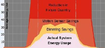
FIGURE 5-2
A growing number of luminaires are now available with integrated automatic lighting controls such as this recessed basket, which includes an integrated sensor. Source: Lightolier.
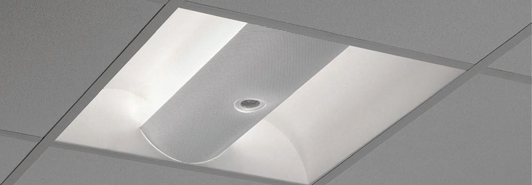
REMEMBER
Most commercial lighting systems include a lamp, a ballast, and a control. The control can switch the lights on and off and/or can dim the lamp’s light output. Lighting control can be manual (based on human intervention) or automatic (no human intervention). It can be localized or global—from a single room to an entire building.
CONTROL FUNCTIONS
Lighting controls can perform one or more of seven basic functions related to on/off and dimming control: on/off, occupancy recognition, scheduling, task tuning, daylight harvesting, lumen depreciation compensation and demand control.
On/Off is the basic control function, achieved through switching.
Occupancy/Vacancy recognition is used in areas that are not occupied all the time but only occasionally. When a person enters the room, the lights turn on automatically. When the person leaves the room, the lights turn off automatically. People often forget to turn off the lights; this strategy is very popular and saves more energy than you might think. Some occupancy recognition devices are manual-on/automatic-off (aka, vacancy sensors), meaning the lights are automatically shut off when a person leaves the room, but not automatically turned on when a person enters the room.
Scheduling is used for areas of predictable occupancy, meaning we know typically when the space will have people in it and when it won’t. The scheduling system dims, turns on or shuts off the lighting system on a predetermined schedule. Local manual overrides are
FIGURE 5-1
A complete lighting upgrade can save energy on multiple levels, including fixed load reduction through reduced luminaires or lowerwattage lamp-ballast systems, and variable load reduction through strategies such as occupancy recognition, scheduling and personal dimming. Source: Light Right Consortium.
Table 5-1. Benefits of automatic dimming controls in various space types. Source: Lighting Controls Association.
SPACE TYPE BENEFIT
Discount Retail Store In an open retail space with daylighting, dimming can reduce electric lighting use but allow the lights to be on, making the store seem "open for business."
Conference Room, Classroom, Auditorium, etc.
Health Care Facility
Dimming lighting can facilitate a variety of visual presentations.
Daylight-driven dimming can provide a smooth and unnoticeable transition to electric lighting as daylight levels decrease, while maintaining the desired light level.
Restaurant Preset scene dimming controls can make changing the ambiance as the day goes on consistent and as easy as pressing a button.
Office Area Even in an open office area, occupants can be given the option of dimming the luminaire over their workstation to suit their personal preferences.
usually provided so that people using the space when it’s supposed to be empty can still turn the lights on and use it.
Tuning entails adjusting the light output of a lighting system to a desired level needed for a task or other purpose, such as aesthetics or mood-setting. This can be achieved through either dimming or switching layers of lighting (such as bi-level switching, in which half of a lighting system is shut off in a space while the other half continues operating).
Daylight harvesting is used to enable lighting systems to respond to available daylight by dimming or enacting some level of switching. A photosensor measures the amount of light in a room that has access to daylight from outside the building. If the measured light is above the designated target light level, then a signal is sent to automatically dim or switch the lamps until the desired target light level is reached. The more daylight that is coming into the space, the more the lighting can be reduced to save energy.
45
CHAPTER 5: ENERGY MANAGEMENT / LIGHTING CONTROLS
REMEMBER
Automatic lighting controls are growing in popularity to save energy and provide other benefits. Automatic control switches or dims the lamps based on an automatic input. This input can be a detected lack of occupancy in a space, measured light levels, a predetermined schedule or other input.
Lumen depreciation compensation takes advantage of the fact that most lighting systems are overdesigned to account for a gradual reduction of light output of lamps as they advance in operating age. Similar to daylight harvesting, this strategy entails measuring available light in the space and dimming the light output to maintain a constant level.
Demand control involves switching or dimming lighting systems during utility peak demand periods, which results in energy cost savings and also potentially significantly lower demand charges.
POPULAR CONTROLS
Control options can be grouped as switching controls, dimming controls, and integrated lighting control systems.
Switching Controls
Local Wall Switches (AC snap switches) are the most commonly used control devices for local lighting control. For best results, switches should be located conveniently for users and to encourage them to turn off the lights when they leave the area. Wall switches also can be layered for flexibility, with different layers of lighting controlled by different switches.
Key-Activated Switches: Key-activated switches are wall switches that turn lighting on and off using a key. This means only authorized lighting users (those who have a key) may turn the lights on and off.
Timeclock: Timeclocks turn the lights on and off based on a defined schedule, best used when one can predict when a given area will have people in it and when it won’t. The timeclock is programmed to turn the lights on and off at preset times.
Occupancy/Vacancy Sensors: Occupancy sensors are automatic switches that control lighting based on the presence or absence of people. They turn the lights on automatically when people enter a room and turn them off automatically, after a preset period of time, after they leave the room. Vacancy sensors require the user to turn the lights on manually and subsequently turn the lights off automatically.
Photosensor Controls: Photosensors, also called daylight or light sensors, measure the amount of light in a space and control the lights according to that amount. When the amount of light in the designated space increases to a certain level, the lighting is switched off. When it falls to a certain level, the lighting is switched on. This technology is often used for daylight harvesting.
Low-Voltage Controls: Low-voltage switching systems provide a
more flexible switching platform than standard line-voltage switches. Low-voltage controls can be used to create a network of controllers that communicate via low-voltage wiring. A simple low-voltage control system includes a network of relays that in turn are used to control different areas, or lighting zones. A single signal can be sent to all relays and instruct them to switch the lights on or off.
Wireless Controls: Wireless lighting control devices and systems utilize wireless technology to communicate commands between sensors, switches and the ballasts or LED drivers connected to luminaires. Radio-frequency (RF) wireless communication is a vastly emerging lighting control technology. While traditional lighting control systems use controllers that are hardwired to each device, wireless RF system control devices communicate through the air using radio waves, eliminating the need for control wiring. The resulting advantages enable elevated lighting control with increased installation flexibility and lower labor installation costs. Wireless RF control systems are ideal for hard-to-wire applications, non-accessible ceilings and asbestos abatement issues.
Step-level HID Controls: Step-level HID lighting controls are relay systems that operate mercury vapor, metal halide, and high-pressure sodium lighting at either full light output or less (e.g., 50%). For example, during times when a warehouse is occupied, the lights could be fully on, and when it’s not occupied, the lights could be switched to 50%.
FIGURE 5-3
Low-voltage control system schematic. Courtesy of National Electrical Manufacturers Association (NEMA).
FIGURE 5-4
Schematic of two-level HID lighting control system. Courtesy of National Electrical Manufacturers Association (NEMA).
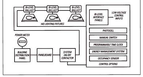
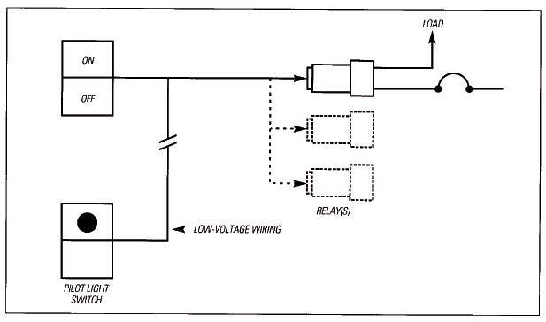
46
Dimming Controls
Wallbox dimmers: Wallbox dimmers are manual controls that give people in a space more control over their light levels.
Integrated Dimmers: Integrated dimmers integrate a variety of features into a wallbox. One feature might be the ability to dim all the lights in a space on a single dimmer. Another might be the ability to create and use presets, where at the touch of a button an exact light level is achieved for a given purpose.
System Dimmers: System dimmers offer lighting control for larger applications where wallbox and integrated products are impractical or higher performance is required. These systems consist of dimmer cabinets and control stations, typically connected with low-voltage control wires.
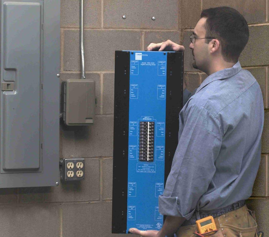
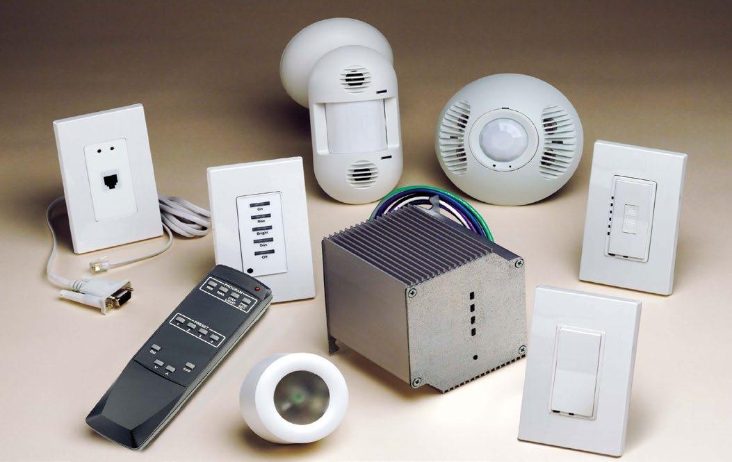
Dimming Ballasts: Variable output ballasts integrate dimming capability into fluorescent and HID ballasts, so that they can dim the lamps according to manual, scheduled or event-based input.

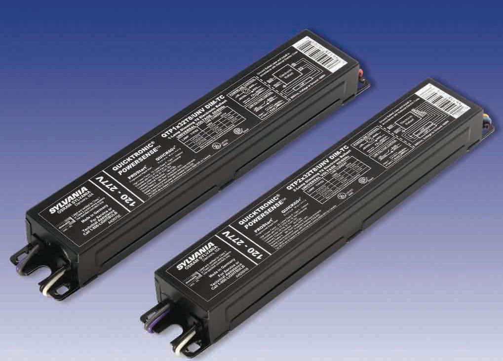
Commissioning
When the installation is complete, the controls should be programmed, calibrated and functionally tested. This often includes 1) light-level or delay-time set points are set, 2) dip switches are set, 3) sensors are aimed for maximum accuracy, 4) preset dimming scenes are set, and 5) the system is tested to make sure it functions as intended. These activities are often essential to achieve and maintain energy savings.
FIGURE 5-5
Dimming system. Courtesy of Leviton Manufacturing.
FIGURE 5-6
Dimming
CHAPTER 5: ENERGY MANAGEMENT / LIGHTING CONTROLS
FIGURE 5-7
Fluorescent
FIGURE 5-8
HID
47
panel. Courtesy of HUNT Dimming.
dimming ballasts. Courtesy of OSRAM SYLVANIA.
dimming ballast. HID dimming ballasts are relatively new and are growing in popularity. Courtesy of Philips Lighting.
CHAPTER 5: ENERGY MANAGEMENT / LIGHTING CONTROLS
Table 5-2.
Selection of controls for various types of spaces: room by room analysis. Source: Lighting Controls Association.
SPACE TYPE USE PATTERN IF... THEN...
Cafeterias or Lunchrooms Occupied occasionally Daylighted
Occupied occasionally
Classroom Usually occupied Multi-tasks like overhead projectors, chalkboard, student note taking and reading, class demonstrations
Consider daylight-driven dimming or on/off control
Consider ceiling-mounted occupancy sensor(s). Make sure minor motion will be detected in all desired locations.
Consider manual dimming
Occasionally occupied Occupied by different students and teachers Consider ceiling- or wall-mounted occupancy sensor(s) and manual dimming. Make sure that minor motion will be detected. Ocassionally occupied Lights left on after hours
Computer Room Occasionally occupied Lights are left on all the time
Conference Room Occupied occasionally Multi-tasks from video-conferencing to presentations
Small conference room
Large conference room
Gymnasium or Fitness Usually occupied Requires varied lighting levels for activities
Hallways Any Occasionally or usually occupied
Daylighted
Health CareExamination Rooms
Occasionally occupied Different lighting needs for examination
Small areas
Health CareHallways Usually occupied Daylighted
Requires lower lighting level at night
Health CarePatient Rooms Usually occupied Different lighting needs for watching television, reading, sleeping and examination
Consider centralized controls and/or occupancy sensors.
Consider occupancy sensors with manual dimming. Be sure that minor motion will be detected and that equipment vibration will not falsely trigger the sensor.
Consider manual dimming (possibly preset scene control)
Consider a wall box occupancy sensor
Consider ceiling- or wall-mounted occupancy sensor(s). Be sure that minor motion will be detected in all desired locations.
Consider manual dimming and occupancy sensors. Be sure that the HVAC system will not falsely trigger the sensor.
Consider occupancy sensors with elongated throw. Be sure that coverage does not extend beyond the desired area.
Consider daylight on/off control
Consider manual dimming
Consider a wall box occupancy sensor
Consider automatic daylight-driven dimming
Consider centralized controls to lower lighting levels at night
Consider manual dimming. Occupancy sensors may not be appropriate
48
CHAPTER 5: ENERGY MANAGEMENT / LIGHTING CONTROLS
Table 5-2.
Selection of controls for various types of spaces: room by room analysis. Source: Lighting Controls Association.
SPACE TYPE USE PATTERN IF... THEN...
Hotel Rooms Occasionally occupied Use primarily in the late afternoon through evening for sleeping and relaxing
Consider manual dimming
Laboratories Usually occupied Daylighted Consider automatic daylight-driven dimming in combination with occupancy sensors.
Laundry Rooms Occasionally occupied Requires high light levels, yet lights are usually left on Consider occupancy sensors
LibrariesReading Areas Usually occupied Daylight Consider automatic daylight-driven dimming
Lights left on after hours Consider centralized controls
LibrariesStack Areas Occasionally occupied Stacks are usually unoccupied Consider ceiling-mounted sensor(s)
Lobby or Atrium Usually occupied but no one "owns" the space
Daylighted and lights should always appear on Consider automatic daylight-driven dimming
It isn't a problem if lights go completely off in high daylight Consider automatic daylight-driven dimming or on/off control
Lights are left on all night long, even when no one is in the area for long periods
Consider occupancy sensors. Be sure that minor motion will be detected in all desired areas.
Office, Open Usually occupied Daylighted Consider automatic daylight-driven dimming
Varied tasks from computer usage to reading Consider manual dimming
Lights left on after hours
Consider centralized controls and/or occupancy sensors.
Office, Private Primarily one person, coming and going
Daylighted Consider manual dimming, automatic daylight-driven dimming, or automatic on/off
Occupants are likely to leave lights on and occupants would be in direct view of a wall box sensor
Occupants are likely to leave lights on and partitions or objects could hide an occupant from the sensor
Consider a wall box occupancy sensor
Consider a ceiling- or wall-mounted occupancy sensor
Photocopying, Sorting, Assembling
Occasionally occupied Lights are left on when they are not needed Consider an occupancy sensor. Be sure that machine vibration will not falsely trigger the sensor.
49
SPACE TYPE USE PATTERN IF...
Restaurant Usually occupied Daylighted
THEN...
Consider automatic daylight-driven dimming
Requires different lighting levels throughout the day Consider manual dimming (possibly preset scene dimming)
Requires different lighting levels for cleaning Consider centralized control
Restroom Any Has stalls
Single toilet (no partitions)
Retail Store Usually occupied Daylighted
Different lighting needs for retail sales, stocking, cleaning
Consider a ceiling-mounted ultrasonic occupancy sensor for full coverage.
Consider a wall switch occupancy sensor
Consider automatic daylight-driven dimming
Consider centralized controls or preset scene dimming control
Warehouse Aisles are usually unoccupied
OCCUPANCY SENSORS
Daylighted
Lights in an aisle can be turned off when the aisle is unoccupied
Occupancy sensors are rapidly becoming a standard feature of new buildings, but are not as common in older buildings, creating a significant upgrade opportunity. Occupancy sensors detect when a room has no people in it, and turn the lights off automatically after a short period of time to save energy. Occupancy sensors can also turn the lights on automatically when a person enters the room, or include a switch so that the lights are turned on automatically by the person entering the room.
Occupancy sensors are most often one of two types, according to what type of technology they use to sense whether a person is in the area or not. Occupancy sensor technology is typically ultrasonic, passive infrared or a combination of the two.
With a passive infrared occupancy (PIR) sensor, the device senses changes in heat radiation in the area. It is important to note that PIR sensors do not detect or measure “heat” per se; instead, they detect the infrared radiation emitted from an object which is different from but often correlated with the object’s temperature.
PIR sensors need a clear “line of sight” between the sensor and the person occupying the room. If the person walks behind a large object and is hidden from the sensor, the sensor will think the room is empty and eventually turn off the lights after the preset time delay. PIR sensors work well outdoors because they do not need to be in an enclosed space to operate.
Consider daylight-driven dimming or daylight on/off control
Consider ceiling-mounted occupancy sensors with elongated throw. Select a sensor that will not detect motion in neighboring aisles, even when shelves are lightly loaded.
With an ultrasonic occupancy sensor, sound waves are emitted by the device, which bounce off of room surfaces and return to the device. If there are changes detected in this reflected pattern, the sensor triggers the lights. Ultrasonic sensors are generally more sensitive and can cover larger areas than PIR sensors, and do not need a clear line of sight between the sensor and the person occupying the room, as long as the space is enclosed with hard surfaces that can reflect the sound waves back to the sensor’s receiver.
Dual-technology sensors use both technologies to get the advantages of each and cancel out the disadvantages. Another type of dual-technology sensor, offered by at least one control manufacturer, was developed as an alternative to ultrasonic occupancy sensors. This sensor combines a PIR sensor with acoustic technology so that the sensor literally “sees” and “hears” the occupant—suitable for applications with obstructions such as restrooms, partitioned offices and classrooms.
Occupancy sensors have an adjustable time delay before the lights go off. You can set the occupancy sensor to turn the lights off from immediately to up to 30 minutes after the room is registered as unoccupied. Time delays avoid continual on/off cycles of the lighting as people may go in out of the space frequently. The shorter the time delay, the greater the energy savings but the greater reduction in lamp life; the converse is also true. In many applications, a minimum time delay of 15 minutes is used.
50
Table 5-2. CONTINUED
Selection of controls for various types of spaces: room by room analysis. Source: Lighting Controls Association.
CHAPTER 5: ENERGY MANAGEMENT / LIGHTING
CONTROLS
Table 5-3.
CHAPTER 5: ENERGY MANAGEMENT / LIGHTING CONTROLS
Ultrasonic wall switch x x x x
Ultrasonic ceiling mount x x x x x x
PIR wall switch x x x
PIR ceiling mount x x x x x
Ultrasonic narrow view X
PIR high mount narrow view x X
Corner mount wide view x x
FIGURE 5-9
Occupancy
FIGURE 5-10
Drawing of a ceiling mounted dual-technology (PIR/ultrasonic) sensor. Courtesy of WattStopper.
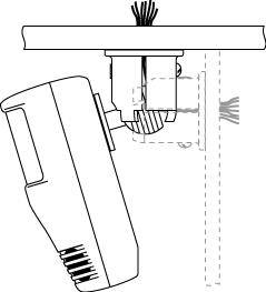
they’re used most. Use of the lights will then slope off until the end of the day. The occupancy sensor chops off the unused lighting time, which saves energy.
The sensors are mounted on the walls, ceilings, workstations or above the doors of the space being monitored. There are several different kinds of coverage patterns and mounting configurations for occupancy sensors, such as ceiling-mounted controls with 360° coverage, ceiling-mounted controls with elongated “corridor” coverage, wall-mounted controls with a fan-shaped coverage pattern, ceiling-mounted controls with a rectangular coverage pattern, workstation sensors that can also control “plug loads” such as computer monitors and other devices, and other types of sensors. In short, a variety of distribution coverage styles and mounting options are available so that the best sensor can be chosen to suit the dimensions and needs of the area. Regardless of where the sensor is located, the control box which contains the relay/switch and a low-voltage power supply for the sensor is usually located in the ceiling.
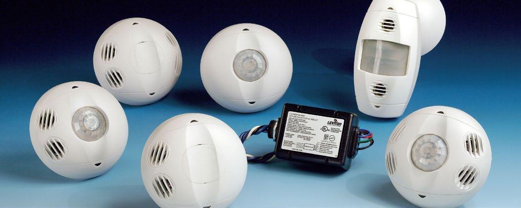
Of these sensors, wall-mounted sensors are the most simple to install. They are self-contained units and replace the wall
FIGURE 5-11
Coverage pattern for a sample ceiling-mounted PIR occupancy sensor. Courtesy of WattStopper.
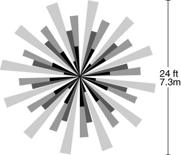
Application
Occupancy sensors have many uses. Outdoors, they can be used to provide low-cost security. Any time a person or animal approaches a building, the lights will go on. Indoors, the sensor provides both security and a way to save energy. Buildings typically go through a daily lighting usage that peaks, similar to shape of an iceberg. In the morning, many lights that are turned on may not actually be needed. As the day continues, light usage peaks—the time of the day when
51
Ideal applications for different types of occupancy sensors. Source: U.S. Environmental Protection Agency.
SENSOR PRIVATE OFFICE LARGE OPEN OFFICE PLAN PARTIONED OFFICE PLAN
CONFERENCE ROOM REST ROOM CLOSETS / COPY ROOMS
HALLWAYS / CORRIDORS WAREHOUSE AISLE AREAS
sensors. Courtesy of Leviton Manufacturing.
CHAPTER
FIGURE 5-12
ENERGY MANAGEMENT / LIGHTING CONTROLS
Table 5-4. Typical energy savings with occupancy sensors. Source: U.S. Environmental Protection Agency.
OCCUPANCY AREA ENERGY SAVINGS
Private Office 13-50%
Classroom 40-46%
switch. Applications include individual offices, storage rooms and bathrooms.
No matter what sensor is installed, it must be time-set. Sensors have built-in timers that allow users to adjust the amount of time the lights will stay on after detecting the room is unoccupied. This prevents the lights from snapping on and off every time somebody goes in and out of a room.
Different sensors also have different levels of sensitivity to major motion (walking or half-step activity) versus minor motion (working at desk). This sensitivity may be tunable based on the sensor. For example, you want a person to be able to sit perfectly motionless for a period of time without the lights going off, which can quickly turn the sensor into a perceived nuisance.
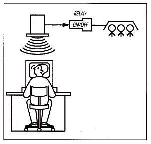
FIGURE 5-13
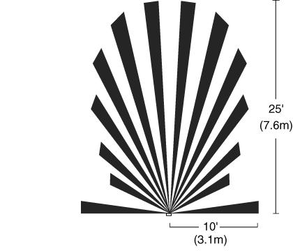
Occupancy sensor system. Courtesy of National Electrical Manufacturers Association.
Conference Room 22-65%
Restrooms 30-90%
Corridors 30-80%
Storage Areas 45-80%
the sensor does not have a false trigger if people walk by an open door outside the controlled space. Adjust sensitivity and location as needed.
PIR sensors are fairly resistant to false triggering but are still susceptible to detecting occupancy if a person walks by an open door outside the controlled room. A masking material can be applied to the lens in these cases to block the line of sight from the sensor into an adjacent room or hallway. PIR sensors cannot detect motion through glass of any type or clarity.
Be sure that the occupancy sensor is compatible with the electronic ballasts in the space, if these are present; make sure the sensor is rated for the size of the lighting load (in terms of total watts) it is assigned to switch; and be sure the sensor is rated for the voltages that are present.
Tuning and Troubleshooting
Occupancy sensors should be tuned after installation. This entails adjusting the sensor’s sensitivity and time delay settings, and making sure the sensor is properly applied for the given space. To make sure it is properly applied, several simple tests can be performed.
One test is the entry test. If the sensor is used to automatically turn on the lighting, then it should do so within two seconds after the person gets three feet into the space. The sensor should NOT turn on the lights when a person passes outside the room with the door open. The second test is the hand motion test. The sensor should turn the lights on if you wave your hand in different directions a foot away from the sensor. And the third test is the perimeter test. Walk and wave your hand in different places around the room to try to find spots where the sensor is least effective in detecting motion.
Note that ultrasonic sensors can be accidentally turned on by vibrations in the room, such as the startup of an air conditioner, or moving air, such as from a heating supply grille. Also make sure
A final aspect of sensor application that all lighting managers should be aware of is that frequently turning the lights on and off can reduce lamp life, as most wear and tear on the lamp occurs during startup. This is why lamp life is based on hours per start.
If the sensor frequently turns the lamps on and off, the increased cost of lamp replacement is typically less than the energy savings, but should be included in any economic benefit calculations. In other words, the sensor provides a larger benefit from the energy savings than the loss of lamp life, so the user just lives with it.
Another option is to use programmed-start ballasts, which are rapid-start ballasts that start fluorescent lamps with less wear and tear on the lamp cathodes, which increases lamp life. As a result, programmed-start ballasts can provide up to 100,000 starts, ideal for applications where the lamps are frequently switched.
YOU’RE READY
Congratulations. If you score well on the Lighting Controls Quiz, consider yourself well on your way to becoming a controls expert. Now you’re ready take on the next chapter: Safety & Code.
52
Coverage pattern for a sample wall-switch occupancy sensor. Courtesy of WattStopper.
5:
CHAPTER 5: ENERGY MANAGEMENT /
ENERGY MANAGEMENT / LIGHTING CONTROLS QUIZ
Check your understanding of this chapter’s material by completing these multiple-choice questions. The answers are on Page 82.
1. The amount of power that a lighting system needs to operate is measured in ________.
a) kWh b) kWh/sq.ft. c) W d) W/sq.ft. (lighting density)
2. The amount of energy that a lighting system uses during operation is measured in ________.
a) kWh b) kWh/sq.ft. c) W d) W/sq.ft. (lighting density)
3. A 300W lighting system operates 8,000 hours per year. How much kWh does this lighting system consume?
a) 1800 b) 2400 c) 11000 d) 18,000
4. A 400W lighting system produces 10,000 lumens of light output. What is the lighting system’s efficacy?
a) 14 lumens per watt b) 25 lumens per watt c) 40 lumens per watt d) 400 lumens per watt
5. A 400W lighting system operates 8,000 hours per year, produces 10,000 lumens of light output, and lights a space that is 4000 square feet. What is the unit power density for the lighting in this space?
a) 0.1 W/sq.ft. b) 2 W/sq.ft. c) 2.5 W/sq.ft. d) 40 W/sq.ft.
6. A 400W lighting system operates 8,000 hours per year, produces 10,000 lumens of light output, and lights a space that is 4000 square feet. What is the energy utilization index for the lighting in this space?
a) 0.8 kWh/sq.ft.
b) 1.4 kWh/sq.ft. c) 8 kWh/sq.ft. d) 14 kWh/sq.ft.
7. A 400W lighting system operates 12 hours per day, 5 days per week, 50 weeks per year. What are the total estimated operating hours each year for this lighting system?
a) 75 b) 300 c) 3000 d) 3500
8. Which of the following is NOT part of the lighting upgrade planning process?
a) Determined the required light level b) Identify lighting options that meet the required light level and quality while also saving energy c) Identify strategies that reduce energy consumption, such as planned lighting maintenance d) Choose the lighting option with the lowest initial cost
9. Which of the following is NOT a popular fluorescent lighting upgrade?
a) Electronic ballasts b) Energy-saving T12 lamps c) T8 lamps d) Pulse-start lamps
10. Which of the following is NOT a popular incandescent lighting upgrade?
a) Compact fluorescent lamps b) LEDs c) Low-wattage metal halide lamps d) 750-hour A-lamps
11. Which of the following is NOT a popular HID lighting upgrade? a) Electronic ballasts b) Dimmable ballasts c) Magnetic ballasts d) Pulse-start lamps
12. Which of the following is NOT a popular lighting controls upgrade? a) Wall switches b) Occupancy sensors c) Dimming system d) Lighting management system
13. Lighting System A costs $1000 to purchase and will save $500 per year in lower energy costs. How long is the simple payback for this lighting system in years?
a) 1 b) 2 c) 3 d) 5
53
LIGHTING CONTROLS
14. Lighting System A costs $1000 to purchase and will save $500 per year in lower energy costs. What is the simple return on investment for this system?
a) 25% b) 50% c) 75% d) 100%
15. When planning a lighting upgrade, which of the following is generally NOT a maintenance consideration?
a) Choosing long-life lamps b) Using instant-start ballasts with parallel lamp operation c) Consolidating lamp types to avoid mistakes during maintenance d) Ensuring all lamps replacing incandescents are screwbase lamps
16. Which of the following is a benefit of automatic lighting controls?
a) Energy savings b) Flexibility c) Security d) All of the above
17. A standard toggle wall switch is an automatic lighting control. a) True b) False
18. What is the function of a scheduling system?
a) Turns the lights on and off based on occupancy b) Controls the lights based on a preset schedule c) Dims or switches the lights based on available daylight d) None of the above
19. What is the function of a daylight harvesting system?
a) Turns the lights on and off based on occupancy b) Controls the lights based on a preset schedule c) Dims or switches the lights based on available daylight d) None of the above
20. A timeclock is an example of what type of control?
a) Photocell control b) Step-level HID control c) Scheduling control d) Lumen depreciation control
21. What is the primary advantage of a low-voltage control system?
a) Allows network of relays to be set up, each controlling a lighting zone, for flexible, large-scale on-off control of a large building area
b) The amount of light in the space is measured continually and light output from the lamps is continually adjusted to maintain the target light level
c) Lighting is activated by a key, meaning only authorized personnel can control the lighting system
d) Encourages occupants to turn off the lights when they leave the room
22. Dimming ballasts are available for both fluorescent and HID lamps. a) True b) False
23. PIR occupancy sensors automatically switch lamps based on detected occupancy using a technology that reads ____________ in an area. a) Changes in reflected sound waves b) Changes in heat radiation c) Changes in availability of daylight d) All of the above
24. Ultrasonic occupancy sensors automatically switch lamps based on detected occupancy using a technology that reads ____________ in an area.
a) Changes in reflected sound waves b) Changes in background heat radiation c) Changes in availability of daylight d) None of the above
25. Occupancy sensors can be used both indoors and outdoors. a) True b) False
26. Why should occupancy sensors be time-set after installation? a) To set their sensitivity to motion in the room b) To establish their coverage pattern c) To avoid false activation of lights d) None of the above
54
CHAPTER 5: ENERGY
/ LIGHTING
MANAGEMENT
CONTROLS
CHAPTER 6: SAFETY AND CODE
SAFETY CONSIDERATIONS
Lighting systems are electrical systems, and, therefore, maintenance technicians are exposed to the potential for contact with hazardous voltages. For this reason, only qualified and properly trained people should conduct maintenance on lighting systems. The supply voltage should be turned off prior to any maintenance or repair of lighting systems. In addition, every lighting management company should maintain a good safety program that should cover personal protective equipment (PPE), scaffolding and lift equipment, hand tools, fall protection, emergency preparedness, hazardous communications, and all applicable regulations and precautions.
For each project, there will be a designated crew lead responsible for the supervision of the field crew, and as such is the key person responsible for ensuring the crew is thoroughly briefed on his company’s safety program and record. He is the one who controls the working environment of his crew—the equipment they use, their working conditions and work habits. He sets the working standards. He must exercise good safety practices that strictly follow all applicable state, local and Federal regulations, and his employer’s and his customer’s safety rules and procedures.
Whether you are a crew lead or a crew member, never ignore an unsafe condition. Take immediate action. Silence implies consent.
On the job safety meeting should focus on discussing safety conditions pertinent to the area or the work to be done; identifying potential hazardous conditions; soliciting crew member comments and suggestions; and creating a team effort and team involvement for safety, as well as productivity.
If you are the crew lead, you must set the example. What you practice, they will practice. The exceptions you take, they will take. The level you establish is what you can expect. Where you lead, they will follow.
View all OSHA standards in Title 29 of the CFR, the Department of Labor’s section of the Code of Federal Regulations.
Standards published in section 29 CFR 1910 pertain to General Industry.
Standards published in section 29 CFR 1926 pertain to Construction Industry.
For more information, consult the U.S. Department of Labor’s OSHA web site, www.osha.gov.
Personal Protective Equipment (PPE): OSHA 29 CFR 1926.28
PPE at its most basic consists of gloves, safety glasses, head protection and proper boots. However, it can extend greatly depending on the work being performed (i.e., fall protection, respirators, insulated clothing). As its name states, this equipment is designed to protect you personally. It is your responsibility to keep your PPE in good condition and functioning properly. Your company should advise you as to what PPE you are required to have as well as inform you of any additional PPE required for job specific duties. Ultimately, you are responsible for your own safety. If you do not have the proper PPE for a specific duty, do not perform the task and inform your company immediately.
Ladders
Ladders shall be maintained in good condition at all times, the joint between the steps and side rails shall be tight, all hardware and fittings securely attached, and the movable parts shall operate freely without binding or undue play. Safety feet and other auxiliary equipment shall be kept in good condition to ensure proper performance.
Ladders with broken or missing steps, rungs, or cleats, broken side rails or other faulty equipment shall not be used; improvised repairs shall not be made. Ladders shall be inspected frequently and those which have developed defects shall be withdrawn from service for repair or destruction and tagged or marked as “Dangerous, Do Not Use.”
REMEMBER
Every field crew member is responsible for demonstrating professionalism and safety. Set the right example and make sure your fellow crew members observe all applicable Federal, state and local regulations in addition to your own company’s and your customer’s safety rules.
OCCUPATIONAL SAFETY & HEALTH ADMINISTRATION (OSHA)
With the Occupational Safety and Health Act of 1970, Congress created the Occupational Safety and Health Administration (OSHA) to assure safe and healthful working conditions for working men and women by setting and enforcing standards and by providing training, outreach, education, and assistance.
Ladders shall be maintained free of oil, grease and other slipping hazards.
Ladders shall not be moved, shifted or extended while occupied. Ladders shall have nonconductive side rails if they are used where the employee or the ladder could contact exposed energized electrical equipment.
Ladders shall not be loaded beyond the maximum intended load for which they were built, or beyond their manufacturer’s rated capacity.
Ladders shall be used only for the purpose for which they were designed.
Allow sufficient room to step off the ladder safely. Keep the area around the bottom and the top of the ladder clear of equipment, materials, and tools.
55
CHAPTER 6: SAFETY AND CODE
Use 3-point climbing (one hand, two feet or two hands, one foot).
FIGURE 6-1
Safe use of a ladder.
OSHA classifies ladders in five types based on duty :

TABLE 6-1
Five ladder types
TYPE DUTY RATING
USE LOAD IN LBS.
IAA Special Duty Rugged 375
IA Extra Duty Industrial 300
I Heavy Duty Industrial 250
II Medium Duty Commercial 225
III Light Duty Household 200
Step Ladders: Stepladders longer than 20 feet shall not be supplied. Stepladders specified shall be of three types: IA, I, or II.
A metal spreader or locking device of sufficient size and strength to securely hold the front and back sections in open positions shall be a component of each stepladder. The spreader shall have all sharp points covered or removed to protect the user.
The top or top step of a stepladder shall not be used as a step.
Extension Ladders: Two-section extension ladders longer than 60 feet shall not be supplied. All ladders of this type shall consist of two sections, one to fit within the side rails of the other, and arranged in such a manner that the upper section can be raised and lowered.
No ladder should be used to gain access to a roof unless the top of the ladder shall extend at least 3 feet above the point of support, at eave, gutter or roofline.
Set the ladder at the proper angle. When a ladder is leaned against a wall, the bottom of the ladder should be one-quarter of the ladder’s working length away from the wall.
For access to an elevated work surface or roof, extend the top of the ladder three feet above that surface.
Before starting work, survey the area for potential hazards, such as energized overhead power lines. Ladders shall have nonconductive side rails if they are used where the worker or the ladder could contact exposed energized electrical equipment. Keep all ladders and other tools at least 10 feet away from any power lines.
Set the base of the ladder so that the bottom sits securely and so both side rails are evenly supported. The ladder rails should be square to the structure against which it is leaning with both footpads placed securely on a stable and level surface.
When using a ladder in a high-activity area, secure it to prevent movement and use a barrier to redirect workers and equipment. If the ladder is placed in front of a door, always block off the door.
FIGURE 6-2
The base of a straight ladder should be one foot for every four of height to the point of support.
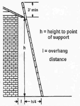
Scaffolds
Scaffolding can provide an efficient and safe means to perform work. However, unsafe scaffolding procedures can lead to accidents, serious injuries and death.
The scaffold should be capable of supporting its own weight and at least four times the maximum intended load to be applied or transmitted to the scaffold and components. Suspension ropes should be capable of supporting six times the maximum intended load. Guardrails should be able to withstand at least 200 pounds of force on the top rail and 100 pounds on the midrail. On complex systems, the services of an engineer may be needed to determine the loads at particular points.
56
CHAPTER 6: SAFETY AND CODE
If you are to select your own scaffold, begin by determining where scaffolds should be used and the type of scaffolding needed. Make sure that the scaffolds meet all government regulations and job specific requirements, plan for any special features of the building structure in relationship to the scaffold, including distinctive site conditions.
Scaffolds are generally rated light, medium and heavy duty.
Light duty scaffolds can support a limited number of employees and hand tools.
Medium duty scaffolds must be capable of safely holding workers, hand tools and the weight of construction materials being installed.
Heavy duty scaffolds are needed when the scaffold must sustain workers, tools and the weight of stored materials.
The footing or anchorage is to be on a solid foundation; sound, rigid, and capable of carrying the maximum intended load without settling or displacement.
REMEMBER
Never allow debris/materials to collect on scaffold. Do not stand on ties, guardrails, or extensions. Do not overreach outside the guardrails. Use 3-point climbing. Exit mobile scaffolds before they are moved.
Fall Protection
Guardrails must be installed on all scaffold platforms in accordance with required standards and at least consist of top rails, midrails and toeboards (if more than 10 feet above the ground or floor). The top edge height of toprails or equivalent member on supported scaffolds shall be installed between 38 inches and 45 inches above the platform surface.
When it is necessary to remove guardrails (for example, to off-load materials), they must be replaced immediately upon completion of the task.
Hard hats should be worn to protect against falling objects. Mesh, screens, intermediate vertical members or solid panels should be used to safeguard employees and the public at lower levels. Ground-level safety can be further provided by erecting canopies; by prohibiting entry into the fall hazard area by barricades and signs, and by the proper placement of materials, tools and equipment on scaffolding.
The full body harness is a belt system designed to distribute the impact energy of a fall over the shoulders, thighs and buttocks. A properly designed harness will permit prolonged worker suspension after a fall without restricting blood flow, which may cause internal injuries. Rescue is also aided because of the upright positioning of the worker.
FIGURE 6-3
Body harness and lanyard.
A lanyard connects the safety harness to the platform or the lifeline. Materials should be made of 5⁄8-inch nylon rope or nylon webbing. Lanyards shall be kept as short as possible to limit fall distance or rigged such that an employee can never free fall more than 6 feet.
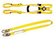
Aerial Lifts
Aerial lifts include the following types of vehicle-mounted aerial devices used to elevate personnel to job-sites above ground: extensible boom platforms, aerial ladders, articulating boom platforms, vertical towers and a combination of any of this equipment.

It may be powered or manually operated. Aerial lifts must be designed and constructed in conformance with the applicable requirements of American National Standards for “Vehicle Mounted Elevating and Rotating Work Platforms,” ANSI A92.2-1969.
Boom and basket load limits must not be exceeded.
Lift controls must be tested each day prior to use to determine that such controls are in safe working condition. Only authorized individuals can operate an aerial lift
The practice of “tying off” to an adjacent pole, structure or equipment while working from an aerial lift is not permitted.
Operators are required to always stand firmly on the floor of the basket. Never sit or climb on the edge of the basket or use planks, ladders or other devices for a work position.
A body harness must be worn and a lanyard attached to the boom or basket when working from an aerial lift.
Do not move the platform unless it is lowered and all outriggers, stabilizers, etc. are clear of the ground. Make sure the platform is clear of collision with any objects. Travel slowly. Move the platform
FIGURE 6-4
Aerial lifts.
57
CHAPTER 6: SAFETY AND CODE
below the luminaire, and then raise the platform to the luminaires.
OSHA Lockout/Tagout Regulations
OSHA 1910.147, “The Control of Hazardous Energy,” commonly referred to as the lockout/tagout standard requires employers to establish a program and utilize procedures “for affixing appropriate lockout devices or tagout devices to energy-isolating devices, and to otherwise disable machines or equipment to prevent unexpected energization, start-up or release of stored energy in order to prevent injury to employees.”
An energy-isolating device is one that physically prevents the transmission or release of stored energy, such as a manually operated electrical circuit breaker or disconnect switch (but not push buttons, selector switches or other control circuit type devices). The energy-isolating device isolates the luminaire from the power supply.
Lockout occurs when a lockout device is placed on the energyisolating device so that the energy-isolating device and the equipment being controlled cannot be operated until the device is removed. If multiple technicians are working on the same lockedout circuit, they all must install their own lock on a multi-lock hasp. The lockout ensures that a luminaire, for example, cannot be accidentally re-activated.
If the energy-isolating device cannot be locked out, the employer must use a tagout system. Tagout occurs when a tagout device is placed on the energy-isolating device to indicate that the energyisolating device and the equipment being controlled may not be operated until the tagout device is removed.
Hazardous Materials Communications
The Hazardous Communication Standard (HazCom), OSHA Standard 1920.1200, was introduced in 1991. It requires employers to inform and train their employees about the hazardous materials they are working with or around. Four principal factors are involved: MSDS, label, employee training and a written communication program all of which are described below.
Material Safety Data Sheets (MSDS), issued by the manufacturer, describes a product and how it should be handled. An MSDS is needed for every hazardous material in your inventory.
Each hazardous product must also have a label which sums up the possible dangers of handling the material. The manufacturer also supplies this.
All employees who could be exposed to the hazardous material must go through employee training, including those who may only walk through the areas.
Your company must design and produce a written communication program which posts:
1. forms of warning (labels, MSDS, etc.);
2. employee information and training; and
3. a list of hazardous materials present.
If your customer’s employees may be exposed to hazardous materials, a written communications program must be developed for them as well.
For more information, refer to OSHA Standard 1910.1200, Hazard Communication.
LAMP AND BALLAST DISPOSAL
Planned lighting maintenance and lighting upgrade operations can result in wholesale replacements of lamps and ballasts. Once lamps and ballasts are destined for disposal, they become “waste” and state and Federal regulations may come into effect.
Provided in this section is a brief summary and description of lamp and ballast recycling. The Federal government mandates minimum requirements, state governments may create more stringent requirements. It is your responsibility to know and understand the regulations surrounding recycling in all areas you perform lighting maintenance. Each lamp or ballast removed potentially becomes universal waste and must be recycled.
Lamps
All lamps may be considered hazardous waste when they are being disposed. The U.S. Environmental Protection Agency (EPA) defines a hazardous waste lamp as a lamp that is characteristically hazardous, meaning it fails EPA’s Toxicity Characteristic Leaching Procedure (TCLP) for mercury.
Disposing of hazardous waste has significant regulatory requirements. In 2000, EPA changed the rules for mercurycontaining lamps to allow them to be classified as universal waste, with fewer regulatory requirements, if they are recycled. A number of companies in the U.S. provide lamp and ballast recycling services.
Options for managing the disposal of mercury-containing lamps according to Federal requirements, therefore, include treating them as hazardous waste, treating them as universal waste (recycling), or to use a type of lamp that is not characteristically hazardous. Recycling typically costs more than hazardous waste landfill costs, but with less regulation and paperwork, and lower storage, collection and transportation fees. The owner also benefits from reduced liability. Require a certificate of destruction from the recycler, naming the generator (facility owner), the involved contractor, the type and quantity of products recycled and date of destruction. This should be shared with your customer as proof of recycling.
In recent years, however, the major lamp manufacturers have voluntarily reduced the amount of mercury in their lamps and made other changes in the operating design of their fluorescent lamps so that they pass the TCLP test and therefore can potentially be disposed of in a municipal landfill, depending on state laws. It’s important to note that while the Federal government mandates minimum requirements, state governments may create stricter requirements. California, Connecticut, Florida, Maine, Minnesota, Rhode Island and Vermont, for example, have banned all mercurycontaining lamps from solid waste landfills and Pennsylvania has eliminated the small-quantity exemption.
58
CHAPTER 6: SAFETY AND CODE
FIGURE 6-5
At a recycling facility, lamps enter the system on a flat conveyor (on the right side of the photo) that moves them into a crusher and separator where their components are stripped of the phosphor powder. Mercury is concentrated into a drum and placed in a thermal retort for mercury recovery (not shown). The other lamp components are sorted into glass by particle size and aluminum endcaps, all of which exit the system on the left side, to re-enter the economy as raw materials. Courtesy of Resource Technology, Inc., Van Meter, Iowa.
PCB Ballasts/Capacitors
Polychlorinated Biphenyls (PCBs) are a hazardous waste regulated by the EPA and are primarily found in the following equipment and materials:
1. Capacitors (Dielectric Fluid)
2. Transformers including fluorescent lightings ballasts (Dielectric Fluid)
3. Hydraulic Systems (Hydraulic Fluid)
4. Circuit Breakers (Dielectric Fluid)
5.
Heat Transfer Systems (Coolant)
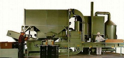
The U.S. banned the manufacture and distribution of PCBcontaining ballasts in 1979, but they are still found in older installations. When handling and storing PCB contaminated materials or any other hazardous materials you should use proper procedures to ensure that such wastes are managed in a safe and environmentally responsible manner. These procedures apply to the packaging, labeling, and record-keeping required.
General guidelines for fluorescent lamp disposal, published on the EPA’s website, are shown below. For a list of lamp recyclers and links to lamp disposal regulations that can vary from state to state, visit www.lamprecycle.org, a web site produced by the National Electrical Manufacturers Association.
Disposal Methods
1. Place waste lamps in the box in which replacement lamps arrived, or in special cartons provided by the lamp recycler.
2. Store lamps in a safe place to avoid breakage, marking the area and recycled material receptacles appropriately to prevent others from accidentally throwing trash in it.
3. Separate and put broken lamps in a heavy plastic bag placed inside a rigid container. If you cannot locate a lamp recycler who will accept them, treat broken lamps as hazardous waste. Many recyclers provide a specific plastic-lined drum for the storage and transportation of broken lamps.
4. Do not place broken fluorescent lamps in metal receptacles. Metal boxes will absorb mercury and become hazardous waste containers.
Collection and Transportation
1. Most lamp recyclers offer transportation services. Waste lamp generators may also contract with a solid or hazardous waste transporter to take lamps to a recycler, or safely transport their lamps themselves.
2. Lamp generators may collect waste lamps from several locations and store them in a central facility to ease transport and recycling.
3. Transportation to another state may require use of a transporter licensed in that state and in compliance with that state’s hazardous waste transportation laws.
Ballasts manufactured after 1979 say, “No PCBs” on their labels. If you don’t see this notice or there is no ballast label at all, it should be assumed that the ballast contains PCBs. The EPA requires that PCBs eventually be disposed in a federally approved incinerator. If the ballast is not leaking PCB-containing fluid, often the surest and simplest method of disposal is to bring in a ballast recycler. If the ballast is leaking, then it must be treated as hazardous waste and incinerated. Whether the ballast is leaking or not, a qualified disposal contractor should handle its disposal.
Non-PCB Ballasts
After 1979, a “non-PCB” alternative known as di (2-ethylhexyl) phthalate, commonly referred to as DEHP, became the standard for use as the dielectric fluid. While DEHP has a low lethal toxicity, studies have shown that it can affect certain organs in low concentrations. DEHP is a known hazardous substance and landfilling non-PCB/DEHP lighting ballast does potentially expose you and your customer to liability. Verify your local requirements for the proper handling and disposal.
HAZARDOUS BUILDING MATERIALS
There are other hazardous materials that may or may not be present as it pertains to your specific lighting project. Please be aware of the risks and take all precautionary steps to ensure that you and your crew are aware of your surroundings and that you have reviewed any and all building reports and MSDSs.
Asbestos
Asbestos is the name given to a group of naturally occurring minerals that are resistant to heat and corrosion. Asbestos became increasingly popular among manufacturers and builders in the late 19th century because of its sound absorption, average tensile strength, affordability and resistance to fire, heat, electrical and chemical damage. It was used in such applications as electrical insulation for wiring and in building insulation. When asbestos is used for its resistance to fire or heat, the fibers are often mixed with
59
CHAPTER 6: SAFETY AND CODE
cement (resulting in fiber cement) or woven into fabric or mats.
In the construction industry, exposure occurs when workers disturb asbestos-containing materials during the renovation or demolition of buildings. The inhalation of asbestos fibers by workers can cause serious diseases of the lungs and other organs that may not appear until years after the exposure has occurred. For instance, asbestos can cause a buildup of scar-like tissue in the lungs and result in loss of lung function that often progresses to disability and death. Asbestos fibers associated with these health risks are too small to be seen with the naked eye.
Many lighting projects today revolve around the removal of asbestos and PCB containing materials. These projects are coordinated between two teams, the abatement (removal) contractor and the lighting contractors. The abatement team contains the work area, removes or encases the contaminated materials, and performs air tests to ensure that the area is safe for the lighting contractors to enter the workspace to replace luminaires and associated wiring.
At no point should any unauthorized personnel enter the containment area before an air clearance has been issued in writing. Please follow all posted warning signs and inform your crew to remain clear of any and all sealed work areas.
Asbestos does not pose a threat when handled properly and all precautions are taken. However to the general public, the mention of the word “asbestos” causes fear and panic.
Due to this fact, when speaking of asbestos on the job or near a worksite, as professionals we use the term ACM, which means “asbestos containing material” so as not to cause undue stress or anxiety to bystanders.
Lead
Lead and lead compounds have been used in a wide variety of products found in and around our homes, including paint, ceramics, pipes and plumbing materials, solders, gasoline, batteries, ammunition and cosmetics.
Lead is particularly dangerous to children ages 1-5 years because their growing bodies absorb more lead than adults do and their brains and nervous systems are more sensitive to the damaging effects of lead. Adults may be exposed to lead by eating and drinking food or water containing lead or from dishes or glasses that contain lead. They may also breathe lead dust by spending time in areas where lead-based paint is deteriorating, and during renovation or repair work that disturbs painted surfaces in older homes and buildings.
Federal law requires contractors that disturb painted surfaces in homes, childcare facilities and schools built before 1978 to be certified and follow specific work practices to prevent lead contamination.
NFPA 70 - NATIONAL ELECTRIC CODE
The purpose of this code is the practical safeguarding of persons and property from hazards arising from the use of electricity. This code contains provisions that are considered necessary for safety.
Compliance there with and proper maintenance results in an installation that is essentially free from hazard but not necessarily efficient, convenient or adequate for good service or future expansion of electrical use.
The NEC is the minimum requirement and all installations should be completed above these standards. Good workmanship practice exceeds the NEC.
Disconnecting Means During Re-Ballasting
Industry data shows that a leading cause of fatalities among electricians is electrocution while working on 277V lighting systems. Some believe that this is partly because electricians often chose to change out ballasts while circuits are energized to avoid removing light from the area being serviced, causing them to ignore applicable warnings and instructions.
The National Electrical Code (NEC) has addressed this situation in Article 410.73(G), “Disconnecting Means,” which addresses changes to how fluorescent luminaires are disconnected prior to electrical work to prevent the possibility of shock hazard.
This Article states: “In indoor locations, other than dwellings and associated accessory structures, fluorescent luminaires that utilize double-ended lamps and contain ballast(s) that can be serviced in place or re-ballasted must have a disconnecting means, to disconnect simultaneously all conductors of the ballast, including the grounded (neutral) conductor if any. The disconnecting means must be accessible to qualified persons.”
This requirement became effective January 1, 2008. If you encounter a luminaire without a disconnect installed, you must terminate and secure power and install a means of disconnect before repairing the luminaire and restoring voltage.
NEC Requirements for Luminaire Support
The installation of adapters, such as compact fluorescent units or an HID conversion kit, into incandescent sockets has raised questions concerning the NEC. Similar questions arise concerning outlet boxes and suspended ceilings when existing luminaires are maintained or new luminaires are to be installed.
The below sections of NEC apply to these situations:
410-15 Supports.
A) General. Luminaires and lampholders, rosettes and receptacles shall be securely supported. A fixture that weighs more than 6 pounds (2.72 kg) or exceeds 16 inches (406 mm) in any dimension shall not be supported by the screw shell of a lampholder.
410-16 Means of Support.
A) Outlet Boxes. Where the outlet box or fitting will provide adequate support, a fixture shall be attached thereto or be supported as required by Section 370-13 for boxes. A fixture that weighs more than 50 pounds (22.7 kg) shall be supported independently of the outlet box.
60
CHAPTER 6: SAFETY AND CODE
B) Inspection. Fixtures shall be so installed that the connections between the fixture conductors and the circuit conductors can be inspected without requiring the disconnection of any part of the wiring. Exception: Fixtures connected by attachment plugs and receptacles.
C) Suspended Ceilings. Framing members of suspended ceiling systems used to support fixtures shall be securely fastened to each other and shall be securely attached to the building structure at appropriate intervals. Fixtures shall be securely fastened to the ceiling framing member by mechanical means, such as bolts, screws or rivets. Clips identified for use with the type of ceiling framing member(s) and fixture(s) shall also be permitted.
XV. Lighting Track
410.104 Fastening. Lighting track shall be securely mounted so that each fastening is suitable for supporting the maximum weight of luminaires that can be installed. Unless identified for support at greater intervals, a single section 1.2m (4 ft.) or shorter in length shall have two supports, and where installed in a continuous row, each individual section not more than 1.2m (4 ft.) in length shall have one additional support.
Circuit Breakers Used for Switching
NEC 240.83(D) states:
Circuit breakers used as switches in 120-volt and 277-volt fluorescent lighting circuits shall be listed and shall be marked SWD or HID. Circuit breakers used as switches in high-intensity discharge lighting circuits shall be listed and shall be marked HID.
Grounding
Luminaires and lighting equipment shall be grounded in accordance to the National Electric Code.
NEC 410.20 states: Luminaires with exposed metal parts shall be provided with a means for connecting an equipment grounding conductor for such luminaires.
NEC 410.21 states: Luminaires and equipment shall be considered grounded where mechanically connected to an equipment grounding conductor as specified in 250.118. See NFPA 70 NEC250.118 for more information on approved grounding conductors.
Conductors
NEC 410.22 states: Wiring on or within luminaires shall be neatly arranged and shall not be exposed to physical damage. Excess wiring shall be avoided. Conductors shall be arranged so that they are not subjected to temperatures above those for which they are rated.
NEC 410.24 states: Luminaires shall be wired with conductors having insulation suitable for the environmental conditions, current, voltage, and temperature to which the conductors will be subjected.
NEC 410.33 states: Branch circuit conductors within 75mm (3 in.) of a ballast shall have an insulation temperature rating not lower than 90 degrees Celsius unless supplying a luminaire listed and marked as suitable for a different insulation temperature.
NEC 402.6 states: Fixture wires shall not be smaller than 18 AWG.
YOU’RE READY
Congratulations! You’re now ready to take the final chapter: Troubleshooting.
61
CHAPTER 6: SAFETY AND CODE
ENERGY MANAGEMENT / LIGHTING CONTROLS QUIZ
Check your understanding of this chapter’s material by completing these multiple-choice questions. The answers are on Page 82.
1. What is the most significant reason that electrical safety is so important?
a) Electricity can cause property damage b) Electricity can cause fires c) Exposure to electricity can be fatal d) None of the above
2. The “lockout” part of the lockout/tagout rule essentially means _____________.
a) After the lighting system is disconnected from the power supply using an energy-isolating device, a lockout device is added to make sure that it stays disconnected b) After the lighting system is disconnected from the power supply using an energy-isolating device, a tagout device is added to make sure that it stays disconnected c) A lockout device is installed on the circuit to disconnect and isolate an energy-using device from the power supply d) If the energy-isolating device cannot be locked out, then a tagout device must be placed in the energy-isolating device
3. The “tagout” part of the lockout/tagout rule essentially means _____________.
a) After the lighting system is disconnected from the power supply using an energy-isolating device, a lockout device is added to make sure that it stays disconnected b) After the lighting system is disconnected from the power supply using an energy-isolating device, a tagout device is added to alert people not to re-energize the lighting system c) A lockout device is installed on the circuit to disconnect and isolate an energy-using device from the power supply d) None of the above
4. Branch circuit conductors within ________ of a ballast shall have an insulation temperature rating not lower than 90 degrees Celsius. a) 3 inches b) 6 inches c) 2 inches d) 1 inch
5. If a circuit breaker is used as a switch in a fluorescent lighting circuit, it shall be listed and rated as: a) GFCI b) AFCI c) SWD or HID d) WMD or PDM
6. The supply voltage to the luminaire must be turned off before servicing or maintenance activities. a) True b) False 7. Proper grounding is required, in accordance with the _________. a) NIOSH Code b) Regional Electrical Code c) National Electrical Code d) Underwriters Laboratory Code
8. Luminaire wires should not be smaller than what size AWG. a) 2 AWG b) 14 AWG c) 16 AWG d) 18 AWG
9. Who is responsible for my personal safety on a job site? a) I am b) The owner c) OSHA d) Safety manager
10. When managing a crew, the most important responsibility is to: a) Follow all safety rules and regulations b) Provide a smoking area c) Provide great customer relations d) Ensure productivity
11. A single section (of track for lighting) 4 feet or shorter in length shall have a minimum of how many supports? a) One per foot b) Two c) Three d) One total
12. What does PPE stand for? a) Personal Protective Equipment b) Practice Perfects Efficiency c) Proper Planning & Education d) Profit Projection Estimate
13. What term do we use to speak publically about asbestos? a) ECM b) HOT c) ACM d) PPE
62
CHAPTER 6: SAFETY AND CODE
14. When installing recessed luminaires in a grid ceiling, it is required to have two separate means of support.
a) From the building structure
b) From the ceiling grid with electrical tape
c) From the nearest pipe or duct work
d) Only when no existing support clips are factory installed on the luminaire
15. Which of the following is NOT an option for disposal of failed mercury-containing lamps?
a) Use a lamp that is not characteristically hazardous and can be disposed in the municipal garbage
b) Recycle the lamp as universal waste
c) Donating them to charity or an applicable non-profit organization
d) Treat the lamp as hazardous waste and send it to a Federally approved incinerator
63
CHAPTER 6: SAFETY AND CODE
CHAPTER 7: TROUBLESHOOTING
UNDERSTANDING, DIAGNOSING AND REPAIRING PROBLEMS
The task of troubleshooting falls under planned lighting management and maintenance. The job of a lighting management professional is to provide an all-encompassing maintenance program including preventative maintenance, responsive maintenance and identifying upgrade potentials.
Preventative maintenance typically means a proactive cost effective approach to maintaining and operating a lighting system over the life of the system.
Responsive maintenance typically means a reactive approach to a problem which includes diagnosing, troubleshooting and repairing problems.
Troubleshooting is detective work. You identify a problem and, through a process of methodical elimination, determine the problem. If a lamp fails, for example, this could be happening for a number of probable reasons. As lighting systems become more and more sophisticated, troubleshooting is becoming a much more involved process. As a result, the successful troubleshooter has to know a lot about lighting and lighting systems.
First, a safety message: Lighting systems use electricity to operate. Electricity can be very dangerous if not treated with respect and strict adherence the guidelines of the Occupational Health and Safety Administration (OSHA) and the safety policies of your employer. Exposure to voltages present in lighting systems can be fatal. Do not attempt any troubleshooting unless you are properly trained and are observing all applicable safety regulations and workplace rules.
ISOLATE THE PROBLEM
Troubleshooting entails isolating the problem to a part of the lighting system and then eliminating the probable causes one by one until the problem is solved.
When isolating the problem, assign it to one of the main parts of the lighting system: 1) the lamp/ballast system, 2) the controls or 3) the luminaire and the physical environment, and 4) the electrical supply.
The lamp/ballast system not only includes lamp and ballast, but also the supporting wiring, fuses when applicable, sockets and, when present, the ignitor. For example, the lamp may not be seated properly in the socket, causing the lamp to fail to light.
The controls include any device placed between the incoming power line and the ballast input, such as switches, occupancy sensors, photosensors, dimming controllers, relays or contactors, etc.
The luminaire includes: the lamp, ballast, fuses when applicable, reflector, socket, wiring, diffuser and housing.
The physical environment includes the air surrounding the lamp, possible high amounts of dirt or moisture and high or low ambient temperatures. The physical environment is important because while air is invisible, it can have a big impact on lighting systems.
Too high a temperature can result in low light output, early failure and the lamps shutting down periodically (cycling), while too low a temperature can result in failure to start, low lumen output and lamp striation, among other problems. The luminaire itself may be causing a high ambient temperature if it’s not properly vented.
The electrical supply itself may be the culprit for some common lighting system problems. For example, if the electrical supply suffers a “brownout” (drop in voltage), lamps may turn off or not be able to start. Conversely, overvoltage situations can shorten the life of incandescent lamps, fluorescent ballasts, HID ballasts and related components and control devices. It is important to involve the customer with precise questions as part of the troubleshooting process. This question and answer process will help guide you to the root cause of the issue(s). Troubleshooting can be as simple as locating a switch that is turned off or as complex as tracing and isolating a shorted power wire or catastrophically failed ballast causing a breaker to trip. In some instances, severe outside forces may cause major lighting component failure. Situations such as power outages, lighting strikes and voltage fluctuations beyond the manufacturers’ voltage tolerance range can cause premature failure of lighting components.
One of the most important troubleshooting steps is to isolate the problem lamp or luminaire from the rest of the system. Very often, simply replacing the lamp with a known good lamp will solve the problem. However, if the problem continues, further troubleshooting work will be required.
REMEMBER
Exposure to voltages present in lighting systems can be fatal. Don’t attempt any troubleshooting unless you are properly trained and you are observing all applicable safety regulations and workplace rules.
REMEMBER
Troubleshooting is a process of elimination, ruling out all possible problems until the root cause is determined.
INTRODUCTION TO TROUBLESHOOTING FLUORESCENT SYSTEMS
Fluorescent systems problems are often caused by poor contact between the lamp and the lampholder, lamp-ballast incompatibility and conditions in the physical environment such as moisture, dirt or heat.
The first step is to determine whether the outage is caused by a failed lamp or ballast. The easiest way to determine this is to
64
CHAPTER 7:
TROUBLESHOOTING
replace the lamp in the problem luminaire with a known good lamp (usually borrowed from a neighboring luminaire). If the lamp operates properly, then the problem is the lamp; simply replace it. If the good lamp has the same problem as the old lamp, then the problem isn’t the lamp and instead is likely the ballast or electrical connections between the ballast and lamp, or the electrical supply itself.
To make a good assessment here, it is useful to know what a failed or failing lamp looks like; often, when a lamp fails to light, it has simply expired due to normal end of life. Possible signs of failure include lamp end darkening (cathode darkening), diminished output, a pink hue, or failure to start.
It is also useful to determine the circuit type for the given fluorescent system: rapid start, programmed rapid start, instant start or preheat:
Rapid start systems are series circuit systems that heat the lamp filaments while applying open circuit voltage (OCV) to facilitate lamp ignition. On this type of circuit, if one lamp on a two-lamp ballast fails to light, the other will not light or light only dimly.
Programmed rapid-start systems are a parallel circuit system that preheats the lamp filaments while not allowing the lamp to ignite, then applies open circuit voltage (OCV) to start the lamp to facilitate lamp ignition. The lamp will experience a one-half to one second delay after switching on while the preheating takes place. This type of starting circuit keeps lamp cathode darkening to a minimum and improves lamp life performance, especially where the lamps are frequently switched on and off, making this type of system a great candidate for occupancy sensor applications. On this type of circuit, if one lamp fails to light, the other(s) will continue to operate fully.
Instant start systems are parallel circuit systems that start as soon as open circuit voltage (OCV) is applied. On this type of circuit, if one lamp fails to light, the other(s) will continue to operate fully.
Preheat start systems are parallel circuit systems that rely on an automatic switch or starter to ignite the lamp(s). The lamp filaments must be preheated before ignition by means of a starter(s). One starter is required for each lamp. On this type of circuit, if one lamp fails to light, the other will continue to operate fully
Finally, another safety warning: Be sure the ballast casing is grounded directly to a properly grounded luminaire. When remote mounted, the ballast casing must be grounded by means of a system ground in accordance with National Electrical Code (NEC) requirements. Grounding eliminates any shock hazard due to ballast leakage or the luminaire housing becoming energized. In addition, OSHA and your employer’s and customer’s workplace safety rules must be observed.
Basic Troubleshooting Procedure
A basic troubleshooting procedure for fluorescent lighting systems includes the steps listed below:
1. Verify the lights are switched on and have proper supply voltage, and the luminaire and ballast are properly grounded.
2. Turn power off before inspection, installation or removal of components.
REMEMBER
A lamp failing or performing poorly is usually the first visible evidence of a problem in the lighting system. The first step in troubleshooting any lighting system is to replace the lamp with a known good lamp. If the new lamp works properly, the problem was the lamp. If the new lamp repeats the problem, then the problem is in the luminaire or electrical system, and further troubleshooting is needed.
3. Verify the problem lamp is seated and making proper contact in the lampholder.
4. Replace the problem lamp with a known good lamp to isolate the problem to a bad lamp or if additional troubleshooting will be required.
5. Confirm lamp and ballast compatibility.
6. Using the wiring diagram on the ballast label, confirm the ballast is wired properly and connected to the correct supply voltage.
7. Check to make sure lampholders, sockets, capacitors, ignitors, wires and other components are not broken, shorted, loose or improperly matched to the application.
8. Replace the ballast if there is proper input voltage and low or no output voltage and all other checks passed.
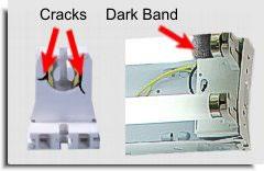
Note that the goal of troubleshooting is to have the lighting system working as designed. This is accomplished by diagnosing, troubleshooting and repairing problems. If a lamp or group of lamps continually experience premature failure, the lamp(s) may appear to be the problem, but actually are a symptom of a bigger issue. Troubleshooting requires experience and time. You must determine and understand the symptoms and lighting products operating characteristics to make an accurate diagnosis.
FIGURE 7-1
Make sure the lamp is properly seated in the lampholders, and that the lamp pins are making proper contact. Next, examine the lampholders for cracking, erosion or arcing. Replace the lampholders if necessary with the power turned off. A dark band at only one end of the old lamp often indicates a lampholder problem. Courtesy of Philips Lighting.
65
CHAPTER 7: TROUBLESHOOTING
CHAPTER 7: TROUBLESHOOTING
REMEMBER
When troubleshooting fluorescent systems, determine whether the problem is the lamp, ballast, luminaire components or the electrical system. Make sure the lamp and ballast are compatible, the ballast is wired properly, and the luminaire and the lighting system has the proper supply voltage.
rated life, lumen output diminishes while energy consumption and risk of non-passive end of life failure increase. In continuously operated metal halide systems, 24 hours per day, 7 days per week, lamps must be turned off a minimum of 15 minutes weekly to minimize the risk of non-passive end of life failure.
For all HID systems, be aware that momentary power interruptions can extinguish the lamp. The lamp must cool down before restarting. Each family has its own restart time, refer to manufacturers data for exact information.
Again, safety comes first. Before any work is started, be sure the ballast and luminaire are properly grounded in accordance with NEC requirements. When performing any troubleshooting work, rigidly observe all OSHA, employer and customer workplace rules and regulations.

REMEMBER
When troubleshooting HID systems, be sure to take into account the operational and end of life characteristics between the lamp types, as a common problem with one lamp type may not be common to another.
INTRODUCTION TO TROUBLESHOOTING HID SYSTEMS
Metal halide, high pressure sodium, low pressure sodium and mercury lighting systems make up the HID lamp family. Of these, high pressure sodium and metal halide are most popular due to high pressure sodium’s high efficacy—expressed in lumens per watt (lm/w)—and metal halide’s good color rendering (CRI) ability.
Like fluorescent lamps, HID lamps are gaseous discharge sources, meaning they rely on a ballast to initiate an arc of electric current through an excited gas medium. Because high pressure sodium and some metal halide lamps need a very high voltage to start the lamp, they require use of an ignitor as well as a ballast and, in most cases, a capacitor.
Usually, the first evidence of a problem will be visible at the lamp, since that is the component that actually produces light. If the lamp is flickering, failing to light or color shifting, we know there’s a problem. As in all troubleshooting situations, isolate the part or parts of the system causing the problem starting with a known good lamp
Because of this, it’s a good idea to be able to separate problems that occur as a natural end of life from premature failure. For example, arc tube darkening happens with almost all aged HID lamps. Some lamps may simply fail in the first few hundred hours due to defects during the manufacturing process. High pressure sodium lamps and some pulse start metal halide lamps may cycle at end of life, meaning the lamp will turn on, then off repeatedly until they fail completely. Metal halide lamp color may become very blue or pink (color shift) as the lamp ages.
Mercury vapor lamps will produce light long after their rated useful life. For all metal halide and mercury vapor lamps operated beyond
Basic Troubleshooting Procedure
A basic troubleshooting procedure for HID lighting systems includes the steps listed below:
1. Verify the lights are switched on, have proper supply voltage and the luminaire and ballast are properly grounded.
2. Turn power off before inspection, installation or removal.
3. If multiple-tapped ballasts are used, the tap must match the connected supply voltage. Connecting to a tap rated for a higher voltage will result in lower light output and wattage, while connecting to a tap rated for a lower voltage will result in faster lumen depreciation. Either will result in shorter lamp and ballast life.
4. Verify if the problem lamp is seated and making proper contact with the base eyelet in the lampholder.
5. Replace the lamp with a known good lamp. Be sure the operative lamp is cool. Hot lamps will not restart immediately.
6. If the lamp needs an ignitor, verify starting voltage at the base eyelet of the lampholder. Check the manufacturer’s rating and replace as needed.
7. Using the wiring diagram on the ballast label, confirm the ballast is wired properly.
8. Check to make sure lampholders, sockets, capacitors, ignitors, wires and other components are not broken, shorted, loose or improperly matched to the application.
9. Replace the ballast if there is proper input voltage and low or no output voltage and all other checks passed.
Since the different lamp types in the HID family each have specific
66
design and operational characteristics, specialized troubleshooting considerations must be taken into account.
High Pressure Sodium Systems
For high pressure sodium and pulse start metal halide systems, below are additional troubleshooting considerations:
1. Lamps in these families require an ignitor to start. If a known good lamp fails to start, the problem may be the ignitor, the ballast, the capacitor or all three.
2. Don’t connect a voltmeter or multimeter to an open or inoperative socket when testing, as it can damage the meter and present a shock hazard. Ignitors have a pulse in excess of 2,500 volts, which cannot be easily measured because it exceeds the voltage rating of typical meters. You can insert a mercury vapor lamp, and if it lights the ignitor is bad. If it does not, the ballast is bad.
3. High pressure sodium lamps are a vacuum jacket lamp and may implode if broken.
4. If the outer envelope breaks during lamp operation, the lamp can remain illuminated, and although ultraviolet emission is not a problem as with mercury or metal halide, the lamp should be replaced immediately, as the exposed lamp components are energized and present a shock hazard.
Metal Halide Systems
For metal halide systems, below are additional troubleshooting considerations:
1. Ensure the lamp is installed and operating in the manufacturersspecified orientation position. Some lamps can only operate base up (BU), base down (BD), or horizontal (HOR).
2. For pulse start metal halide systems, do not connect a voltmeter or multimeter to an open or inoperative socket when testing, as it can damage the meter and present a shock hazard. Ignitors have a pulse in excess of 2,500 volts and cannot be easily measured because it exceeds the voltage rating of typical meters. You can insert a mercury vapor lamp and if it lights the ignitor is bad. If it does not, the ballast is bad.
3. The open circuit voltage (OCV) of a Probe Start Metal Halide lamp is listed in the manufacturers catalog and can be measured with a true RMS meter.
4. Slight lamp to lamp color variation is normal with standard metal halide lamps.
5. Lamps may need up to two days of operation for lamp color to stabilize.
6. f the outer bulb is broken or punctured, UV radiation may leak, and the exposed lamp components are energized, presenting present a shock hazard.
7. Turn off the power and replace the lamp immediately. Selfextinguishing metal halide lamps are available that automatically go out when the outer bulb is broken.
Mercury Systems
For mercury systems, below are additional troubleshooting considerations:
1. Handle lamps carefully to avoid scratches or cracks in the glass bulb, which can shorten lamp life.
2. If the outer bulb is broken or punctured, UV radiation may leak, and the exposed lamp components are energized, presenting a shock hazard. Turn off the power and replace the lamp immediately. Self-extinguishing lamps are available that automatically go out when the outer bulb is broken.
3. If the line voltage experiences fluctuations, consider a ballast type that provides proper regulation.
TROUBLESHOOTING GUIDES
Below are guides for troubleshooting incandescent, fluorescent and HID lighting systems. Some lamp and ballast manufacturers publish their own guides that are also useful.
67
CHAPTER 7: TROUBLESHOOTING
CHAPTER 7: TROUBLESHOOTING
TROUBLESHOOTING INCANDESCENT LAMPS
SYMPTOM POSSIBLE CAUSES SOLUTIONS
Lamp won’t light Normal end of life
Lamp not seated in socket properly
Lamps fail in accordance with their morality curves; replace the lamp
Tighten the lamp; if this doesn’t work, de-energize the luminaire and gently bend out the metal contact tab inside the socket to provide good contact
Lamp is defective Replace the lamp
Improper lamp for the luminaire; incandescent lamps may fail violently if, when hot, they come into contact with any liquid or metal part of a luminaire
Improper burning position
Short average life High supply voltage
Lamps operating near neon tubing
Vibration or shock
Improper burning position
Deposit on inside of the glass envelope Defective lamp
Blistering/Bulging on lamps High operating temperature
Verify luminaire ratings; replace with proper lamp and ensure that the lamp does not contact any metal part of the luminaire
Ensure that the lamp is operating in its proper burning position as specified by the lamp manufacturer
Overvoltage significantly reduces incandescent lamp life. For example, a 120V lamp operated on a 125V circuit suffers a 30 percent loss in life
Install metal shield between neon and incandescent lamps
Replace with rough-service or vibration-service lamp, which is more resistant to vibrations/shocks, or a compact fluorescent lamp
Ensure that the lamp is operating in its proper burning position as specified by the lamp manufacturer
Air is entering the lamp through a crack; replace the lamp. Check for signs of moisture, which can result in cracks; replace with a siliconecoated lamp
Check to make sure the lamp is the appropriate wattage for the luminaire; replace with the right lamp. Also check for signs of moisture, which can result in cracks; replace with a silicone-coated lamp. Finally, check for a manufacturer defect; replace the lamp
68
TROUBLESHOOTING FLUORESCENT SYSTEMS
SYMPTOM POSSIBLE CAUSES
Lamp does not light, or starts erratically or slowly
Normal end of life failure
Lamps are not aligned/seated properly in their sockets
There is a defective lamp or a problem within the luminaire
If rapid start lamps take 5-6 seconds to light, and slow starting is accompanied by excessive darkening of one end of a lamp after a short period of operation, then one electrode may not be receiving the required cathode heating current
Given a compact fluorescent amalgam lamp, slower starting versus mercury lamps is normal. Non-amalgam compact fluorescent lamps require about 3 minutes to reach full brightness, while amalgam lamps require a longer time
With a T5 lamp, slower starting versus T8 and T12 linear fluorescent lamps is normal
Cold ambient temperatures or drafts
On newer T5 or smaller diameter lamp installations, the ballast may have an end-of-life (EOL) sensing circuit that terminates supply voltage to the lamp.
Failed ballast
Known good lamps are not lighting (preheat ballast)
Manual reset starter is not reset
Lamp and ballast are not compatible
The starter has failed
Improper or failed connections
Problem with ballast
Known good lamps are not lighting
Lamp and ballast are not compatible
Socket(s) are oxidized and making poor electrical contact
Problem with luminaire wiring. With instant start lamps, improper or broken wiring can result in high temperatures that burn contacts and discolor plastic in the lampholders
Failed ballast
SOLUTIONS
Lamps fail in accordance with their morality curves; replace the lamp
Position lamps properly
Install a known good lamp to determine if the problem is in the lamp or within the luminaire
With lamps removed from the sockets, check filament heating current. This can be done with available testers. If no current is found, check for an open circuit caused by poor or improper connections, broken or grounded wires, or failed ballast. Verify proper wiring per the ballast label diagram
Expected performance; continue operation
Expected performance; continue operation
Consider jacketed lamps, enclosed luminaires or cold temperature rated ballasts
Cycle the power off, then on again to reset the circuit
Replace the ballast
Push button on starter
Ensure lamp-ballast compatibility
Replace the starter
Check luminaire wiring for incorrect connections, loose connections or broken lampholders or wires. Refer to the wiring diagram printed on the ballast or in the manufacturer’s catalog
Check the ballast to see if the label agrees with the application with regard to temperature limitations and lamps. Replace the ballast if faulty or inappropriate
Ensure lamp-ballast compatibility and replace as needed
Replace socket(s) as needed
Verify the wiring against the wiring diagram on the ballast label or manufacturer’s catalog, and correct as needed
Replace the ballast
69
CHAPTER 7: TROUBLESHOOTING
CHAPTER 7: TROUBLESHOOTING
TROUBLESHOOTING FLUORESCENT SYSTEMS CONTINUED
SYMPTOM POSSIBLE CAUSES
Early lamp failure
Lamp has failed normally. Individual lamps do not fail in a predictable manner, only large groups of lamps do; at rated life, 50 percent have failed, and 50 percent will fail afterwards
The first lamp that failed on a series sequence ballast was not replaced promptly
SOLUTIONS
Replace the lamp
Replace the failed lamp(s) as needed
Reduced average life
Frequent starting
Lamp/ballast incompatibility; for example, HO lamp may be operating on VHO ballast, or T8 lamps on a T12 ballast; each is not a compatible combination
Frequent lamp switching reduces average life. Consider upgrading to programmed start ballasts
Ensure lamp-ballast compatibility and replace as needed
Heavy blackening at ends of lamp and short lamp life
Defective lamp, open wiring or poor wiring in socket, poor contact in the socket
An instant start lamp is flickering
Failed ballast
One lamp is not lighting, the other is glowing only dimly on a two-lamp series sequence ballast
Both lamps are out on a two-lamp series sequence ballast
The lamp that is not lighting (second lamp in the series circuit) has reached normal end of life
The first lamp in the series circuit has reached normal end of life
Seat lamps properly; if they are already seated properly, then check for proper ballast operation
Replace the lamp promptly
Replace the ballast
Replace the failed lamp
Replace the failed lamp; if both lamps do not light, then there may be a problem with the ballast (also see “known good lamps are not lighting”)
Blinking (preheat ballast)
Ends of lamp are glowing, but the lamp does not light fully
Swirling, fluttering or spiraling effect in the lamp (striation)
Normal end of lamp or starter life
Failed starter
Some lamps experience this during normal operation
Low ambient temperature
Lamp and ballast are incompatible
Problem in the ballast
Replace the lamp or starter as needed
Replace the starter
Will stop after hours of operation
Check the ballast label for minimum starting temperature; replace ballast with cold service ballast, jacket the lamps or use an enclosed luminaire
Ensure lamp-ballast compatibility and replace as needed
Replace the ballast
70
SYMPTOM POSSIBLE CAUSES
Dark spots or streaks on the lamp
These are droplets of condensed mercury that sometimes show up in new lamps and eventually evaporate after a few hours
A heat-conducting object such as a reflector or louver, is too close to the lamp envelope conducting heat away and creating a cold spot where mercury can condense
SOLUTIONS
Continue operation
The distance between the object and the lamp should be increased
Lumen output lower than anticipated
Normal ballast operation
Line voltage dips present (brownout situation)
Ambient temperatures too high or low
A heat-conducting object, such as luminaire reflector or louver, is too close to the lamp envelope
With a mercury-containing compact fluorescent lamp, the lamp’s operating position may be affecting lumen output
Check the ballast factor for this ballast, which expresses the fraction of published lumens that the ballast delivers
Determine if there is currently a brownout situation present; wait for voltage to recover
Check for drafts. Consider jacketed lamps, enclosed luminaires and/or cold weather ballasts for cold temperature or drafty applications. Check for high ambient temperatures and cool the luminaire as needed
Increase the distance between the object and the lamp envelope
Use lamps in correct operating orientation or consider amalgam lamps, which are less sensitive to burning position
Variations in lamp color
Allow lamps to operate for 100 hours’ “burn-in” time before checking for color variations
Lamps replaced were not the same color temperature as the removed lamps; e.g., failed 3000K lamps may have been replaced by 4000K lamps
Multiple production runs that produced lamps within standard but with slight variations in color between the runs
Lamps can experience a very slight color shift as they age
Dirty luminaires, and variation in the finish of the reflectors and/or lenses of the luminaire can produce variations in the color appearance of the light leaving the luminaire
Improper wiring
With a mercury-containing compact fluorescent lamp, it may not be operating in a proper burning position
A heat-conducting object, such as luminaire reflector or louver, is too close to the lamp envelope
Continue operation
Ensure that color temperature for the lamp is as specified and replace as needed
Replace with new lamps of the same color temperature and CRI
Relamp with new lamps of same color temperature and CRI
Clean the luminaires on a scheduled periodic basis
Ensure that the wiring is in accordance with the diagram on the ballast label
Use lamps in correct operating orientation or consider amalgam lamps, which are less sensitive to burning position
Increase the distance between the object and the bulb wall
71
CHAPTER 7: TROUBLESHOOTING
TROUBLESHOOTING FLUORESCENT SYSTEMS CONTINUED
TROUBLESHOOTING FLUORESCENT SYSTEMS CONTINUED
SYMPTOM POSSIBLE CAUSES
Ballast noise Normal ballast hum (magnetic ballasts)
Premature ballast failure
SOLUTIONS
Continue operation or replace with electronic ballast
Vibration of loose luminaire or components, amplifying normal ballast hum Tighten or replace as needed
Problem with the ballast Replace the ballast
Heat. Every 10°C increase in ballast case temperature can reduce the ballast’s life by 50 percent. High temperatures may be caused by high supply voltage, high amounts of ambient heat in the space, ceiling materials, mounting distance from the ceiling and the luminaire’s design. Consult the ballast manufacturer’s specifications for maximum ballast case temperature rating
Improper ballast for application
TROUBLESHOOTING HID SYSTEMS
SYMPTOM POSSIBLE CAUSES SOLUTIONS
Lamp will not light (core & coil ballasts)
Normal end of life
Lamp not receiving a pulse from the ballast (e.g., pulse start lamp connected to a standard metal halide ballast)
Igniter is too far from the socket and pulse is depleted
Lamp is damaged, which caused lamp failure
Cool the ballast. This can be achieved by using different ceiling insulation materials, installing fans or lowering the luminaires a greater distance from the ceiling. Other solutions are to install luminaires with proper thermal management capabilities; or install remote-mounted ballasts or ballasts rated to operate at the temperature profile of the application
Replace with ballast appropriate for the application
Lamps fail in accordance with their morality curves; 35-50 percent of HID lamps will fail before rated average life, depending on the lamp type. Replace the lamp
Ensure lamp-ballast compatibility and replace as needed
Ensure that the igniter and/or ballast is installed per manufacturers specifications to supply an adequate pulse to start the lamp. Standard ignitors must be installed within 2 feet of the lamp
Check for cracks or breaks in the lamp envelope that allows air to enter the lamp and cause arc tube seal failure. Cracks can be caused by rough handling, contact with metal surfaces, or by water droplets contacting an operating lamp. Consider lamps that automatically extinguish if the outer envelope is broken or punctured to prevent leakage of ultraviolet rays (metal halide and mercury lamps)
Lamp is loose in the socket Poor contact between the lamp base and the socket. Tighten the lamp or replace the socket as needed
Problem with the lamp or within the luminaire
Incorrect lamp, ballast, capacitor or starter
Low temperature
Replace the lamp with a known good lamp to diagnose the problem
All components must be compatible. Ensure appropriate components are installed. Replace as needed
Lamps require high ballast voltage to start at low temperatures. Check the ballast label for its minimum starting temperature. Replace with correct ballast if needed
Faulty socket or wiring Check the socket and wiring for loose contacts, poor connections or broken wires. Correct as needed
Ballast and/or the starter are located too far from the lamp
Voltage drop in wiring results in insufficient voltage delivered to light the lamp. Check the ballast and starter labels to determine maximum allowable distance. Correct as needed
72
CHAPTER 7:
TROUBLESHOOTING
SYMPTOM POSSIBLE CAUSES SOLUTIONS
Lamp will not light (core & coil ballasts)
Continued
Improper wiring
Faulty capacitor. Disconnect the capacitor and discharge it. Use appropriate caution as this procedure presents exposure to potential shock hazard
Defective safety microswitch
Check the wiring diagram on the ballast label or in the manufacturer’s catalog. Correct as needed
The effect on starting and operating performance depends on the lamp, the ballast type and whether the faulty capacitor is shorted or open. Check the continuity of the capacitor with an ohmmeter on its highest scale. If the capacitor is not faulty, the meter will read low resistance, which will gradually increase. If the capacitor is open, the meter will read high resistance. Replace as needed
Some luminaires feature a microswitch that prevents the lamp from operating unless the lens is closed. The switch may have failed, preventing input voltage to the ballast even if the lens is closed. Confirm proper switch operation and replace as needed
Inoperative ballast (systems not using starter)
Inoperative ballast or starter (high pressure sodium and pulse start metal halide systems)
If all previous checks do not find the problem, replace the ballast kit. Signs of ballast failure may include swollen or charred capacitors. The failure mode of a ballast is often the failure of the capacitor, with low power factor operation and high current that lead to excessive heat and failure of the ballast
If all previous checks do not find any problem, check the ballast by installing a test lamp in the socket. If the test lamp does light, replace the starter. If the test lamp does not light, replace the ballast kit. Check the ballast label or the manufacturer’s catalog for the proper replacement. When checking 35-150W/55V ballasts, use a 120V incandescent test lamp of equal or greater wattage. For ballasts 150W/100V and higher, use a mercury test lamp
Short lamp life
Low supply voltage
Check the voltage. Be sure supply voltage matches the ballast tap used
Overwattage operation of the lamp Faulty components are causing very high lamp current.
Look for obvious lamp damage— punctured or cracked bulb, outer bulb discoloration, bulges in the arc tube, burned ends of the arc tube, wires melted
Check the capacitor rating. In addition, the lamp may have been damaged during installation or transport, shortening life. Finally, the lamp (metal halide) may be burning in the wrong operating position, resulting in bulging in the arc tube
Capacitor is shorted Disconnect, discharge and check the capacitor (use caution and proper procedures as the capacitor presents possible electroshock hazard)
Faulty ballast
Check the ballast with a known good lamp and replace as needed
Ballast incorrect for supply voltage Check the ballast label. Replace as needed
Improper ballast voltage tap connection
Incorrect lamp, ballast, capacitor or starter
Check the ballast taps against the verified supply voltage and the wiring diagram on the ballast label or in the manufacturer’s catalog. Correct as needed
All components must be compatible. Check all labels and replace the incorrect components.
73
CHAPTER 7: TROUBLESHOOTING
TROUBLESHOOTING HID SYSTEMS CONTINUED
TROUBLESHOOTING
TROUBLESHOOTING HID SYSTEMS
SYMPTOM POSSIBLE CAUSES SOLUTIONS
Lamp cycling on and off
High pressure sodium lamp has reached normal end of life
Slightly contaminated arc tube in metal halide lamp
Position oriented high-output metal halide lamp in wrong socket
The operating voltage of a high pressure sodium lamp rises during life, eventually exceeding the open circuit voltage of the ballast; the lamp is extinguished. The lamp cools, and the ballast restarts the lamp. The voltage draw of the lamp rises past the voltage limit of the ballast and the lamp is extinguished again. The cycle continues until the lamp is replaced. This repeated starting can cause premature starter failure. Replace the lamp immediately
Allow the lamp a burn in time of up to 100 hours and
Horizontal high-output lamps feature a special mogul base with a locking pin for correct orientation, which must be properly matched to the socket. Base-up and base-down high-output lamps utilize a standard mogul base but must be installed in accordance with manufacturer’s orientation specification. If not properly oriented, the lamp may fail prematurely and produce lower lumen output, or may not light at all
Problem with the lamp or within the luminaire
Replace the lamp with a known good lamp to diagnose the problem
Incorrect lamp, ballast, capacitor or starter All components must be compatible. Check the labels and replace the incorrect component(s)
Faulty socket or wiring Check the socket and the wiring for loose contacts, poor connections, shorted or broken wires. Correct as needed
Low supply voltage or voltage dip Check voltage. Check for other equipment on the line that could cause voltage dip
Lamp cycling on and off (F-can or encasedand-potted ballasts)
The ballast is reaching operating temperatures above the rating of the thermal protector in the ballast and is disconnecting the ballast from the supply line
Same probable causes as with core & coil ballasts
All lamp and luminaire components are correct, but the ballast is being overheated by poor air circulation or insulation around the luminaire
The ballast overheats, the protector opens the circuit, the ballast is disconnected and the lamp goes out. The ballast cools, the protector closes the circuit, the ballast is reconnected and the ballast starts the lamp. This cycle repeats. Make sure no insulating materials are in contact with the luminaire housing and thermal protector
Take corrective action as needed
Remove the insulation. Improve the air circulation
Failed ballast If all tests do not disclose any problem, replace the ballast
74
CONTINUED CHAPTER 7:
TROUBLESHOOTING HID SYSTEMS CONTINUED
SYMPTOM POSSIBLE CAUSES SOLUTIONS
Low lumen output
Normal lamp lumen depreciation Relamp at periodic intervals to maintain desired illuminances
Problem with the lamp or within the luminaire Install a known good lamp to determine where the problem is
Incorrect ballast, lamp or capacitor Check the lamp and ballast labels. Replace incorrect components
Low supply voltage or incorrect ballast tap
Check the ballast taps against the supply voltage and the wiring diagram on the ballast label or in the manufacturer’s catalog. Correct as needed
Faulty capacitor Disconnect, discharge and check the capacitor, replacing it if it’s faulty. Use correct procedures to prevent shock hazard from the capacitor
Failed Ballast
Color variation among metal halide lamps
If all tests do not disclose any problem, replace the ballast
Some color variation between lamps is typical The color appearance of metal halide lamps will vary within the arc tube tolerances. The ballast, the luminaire characteristics and supply voltage do not affect lamp color rendering. In addition, up to two days of operation in an installation may be required to stabilize the color of a lamp and the uniformity among a group of lamps
75
CHAPTER 7: TROUBLESHOOTING
CHAPTER 7: TROUBLESHOOTING
Check your understanding of this chapter’s material by completing these multiple-choice questions. The answers are on Page 82.
1. Which of the following is NOT a general troubleshooting step?
a) Observe visual symptoms b) Isolate the cause c) Fix the problem d) Replace the entire luminaire regardless of problem
2. Before troubleshooting, the supply voltage to the luminaire must be turned off.
a) True b) False
3. Ballasts, HID starters, capacitors and luminaires must always be grounded in accordance with the National Electrical Code.
a) True b) True, but only in a few applications c) False
4. Troubleshooting can be performed by anyone, despite possible exposure to hazardous voltages.
a) True b) False
5. If an incandescent lamp does not light, which of the following is NOT a possible cause?
a) Normal end of life b) Lamp not securely seated in the socket c) Manufacturer defect or shipment damage d) Faulty wiring to the ballast
6. If an incandescent lamp experiences a short average life, which of the following is NOT a possible cause?
a) High supply voltage
b) Lamps operated near “neon” tubing c) Low ambient temperature d) Vibration and/or shock
7. If vibration and/or shock cause general service incandescent lamps to burn out prematurely in a given application, what are the TWO best courses of action?
CIRCLE TWO ANSWERS.
a) Replace with rough and vibration service incandescents
b) Correct supply voltage
c) Replace with compact fluorescent lamps d) Apply a new coat of silicone onto the bulbs
8. Which of the following is a probable cause of an incandescent lamp experiencing a heavy deposit on inside of the bulb (may be yellowish, bluish or black)?
a) Leaking or defective lamp b) Lamp base not making good contact with the socket contacts c) High supply voltage d) High operating temperature around the lamp
9. If air has entered an incandescent lamp, causing a heavy deposit to form inside the bulb, what is the best course of action if cracks are found on the bulb? a) Replace with vibration-resistant lamps b) Replace with moisture-resistant silicon-coated lamps c) Remove the entire luminaire and forget about it d) Clean the luminaire and replace the lamp with the same type
10. What is the most likely cause of blistering or bulging being made on an incandescent lamp bulb? a) No cathode heat b) High supply voltage c) Frequent starting d) High operating temperature around the lamp
11. If a fluorescent lamp catalog says that a particular lamp will last 20,000 hours at three hours per start and your customer operates it to specification but lamps start failing at 10,000 hours, what’s the most likely cause? a) The lamps are being operated by a magnetic ballast b) Poor cathode heat c) High ambient temperature inside the luminaire d) Lamps are failing normally in accordance with mortality curve
12. If fluorescent lamp life is reduced for a large group of lamps, what is most likely happening? a) The lamps are operated at frequent starts (short hours per start) b) Low supply voltage c) No cathode heat d) None of the above
13. “Banding” and “spotting” are signs of what? a) No cathode heat b) High supply voltage c) Normal fluorescent lamp operation d) None of the above
76
CHAPTER 7: TROUBLESHOOTING
14. If a Slimline lamp end is blackened and the lamp will not light after many hours of operation, which of the following is most likely the problem?
a) The lamp has reached normal end of life
b) The lamp is defective c) The lamp is incompatible with the ballast d) None of the above
15. If a rapid start lamp end is severely blackened and the lamp will not light after having been operated only a short time, which of the following is most likely the problem?
a) Poor cathode heat
b) Normal end of life
c) Bulb is punctured or broken d) None of the above
16. If an HID lamp has operated for thousands of hours but fails before its published average life, and no circuitry or ballast problems are found, what is the most likely problem?
a) Ballast failure
b) High supply voltage c) Poor contact with the ballast d) The lamp has reached normal end of life in accordance with the mortality curve
17. Suppose you install a large group of metal halide lamps. Some of the lamps differ from the rest in color appearance. What do you do?
a) Check supply voltage b) Replace the ballast
c) Leave them alone; color variation among metal halide lamps is normal (or you could install ceramic metal halide lamps for better color consistency)
d) Replace the lamps
18. Suppose you just installed a large group of fluorescent lamps and ballasts. When you re-energize the luminaires, you find some of the lamps are not starting or are starting erratically. What do you do?
a) Check lamp seating
b) Position lamps properly
c) Install known good lamps to determine where the problem is; if good lamps light, check the removed lamps in a known problem-free luminaire
d) All of the above
19. When troubleshooting fluorescent lamp-ballast systems, if all other checks in the luminaire do not disclose the problem, what should you do?
a) Replace the luminaire
b) Replace the wiring
c) Replace the ballast
d) Install known good lamps
20. Suppose you install a large batch of fluorescent lamps and all of them light. But you come back a week later on a service call for another room and find some of the lamps won’t start. Which of the following is NOT a troubleshooting step in this case?
a) Clean the lamps if they’re dirty
b) Check for proper seating of the lamps
c) Check lamp and ballast labels and replace incompatible components
d) Check amount of halogen gas in the lamp and refill as needed
21. Suppose you’re going through a series of troubleshooting steps and you’re pretty sure that the problem is no cathode heat. Which of the following is NOT a sensible next step?
a) Check for proper seating of the lamps
b) Check sockets to see if they’re broken or dirty
c) Check for heater voltage coming from the ballast to see if there’s a wiring or ballast problem
d) Measure temperature in the luminaire with a thermometer
22. On a service call, you notice that in many four-lamp luminaires, two fluorescent lamps will not light; they are always the center two or the outer two lamps. The reason could be that that the ballasts are series sequence ballasts, which operate the lamps in series. The first lamp must have failed and that meant the second lamp was denied starting voltage.
a) True b) False
23. If the ends of a lamp remain lighted in a preheat circuit, which of the following is a likely cause?
a) Starter has failed; replace the starter b) The ballast has failed; replace the ballast c) Incorrect lamp or ballast; check labels and replace improper component d) Low temperature around the lamps; shield the lamp from cold air
24. When finished troubleshooting a luminaire, which of the following should you do?
a) Leave the area as good or better than when you found it b) Re-energize luminaire to make sure problem is fixed c) Tag the luminaire to note it as a “problem luminaire” d) All of the above
25. You have just finished installing 100 metal halide lamps powered by core-and-coil ballasts. Some of the lamps won’t light. What should you do?
a) Tighten the lamp; it may be loose in the socket b) Replace the lamp with a known good lamp; this determines whether the problem is in the lamp or in the luminaire c) Check the labels and replace the incorrect component(s); the lamp, ballast or starter may be incorrect d) All of the above
77
CHAPTER 7: TROUBLESHOOTING
26. Which of the following is NOT a probable cause if an HID lamp powered by a core-and-coil ballast will not light?
a) Ballast and/or starter are located too far from the lamp b) Faulty socket or wiring c) Oxidation of the lamp cathode d) Low temperature
27. If all lamp, capacitor and wiring checks fail to produce the problem causing an HID lamp to fail to light, then the problem is probably with the:
a) Capacitor b) Ballast and/or starter c) Wiring d) None of the above
28. You install a large group of HID lamps and they all light. But a month later, you return on a service call and some of the lamps have failed. Which of the following is NOT a likely problem?
a) Overwattage operation of the lamp; faulty components are causing a very high lamp current b) The capacitor has shorted c) Faulty or incompatible ballast d) High ambient temperature
29. Fluorescent lamp “flicker” is: a) An annoying visual effect of a lamp appearing to perceptibly turn on and off several times per second b) A hum produced by lamp-ballast operation c) When a fluorescent lamp turns on and off every several minutes
d) None of the above
30. Lamp “cycling” is:
a) When a ballast is overheating periodically, causing it to be disconnected from the power source until it cools and is reconnected b) When a lamp appears to perceptibly turn on and off several times per second c) When a lamp is broken d) None of the above
31. If an HID lamp is cycling on a core-and-coil ballast, install a known good lamp to determine where the problem is. If the known good lamp operates normally, check the socket and the wiring for loose contact, poor connections or broken wires. Then check voltage. If no problem is revealed, replace the ballast.
a) True b) False
32. You install a group of high pressure sodium lamps and everything goes fine, but you come back a week later and you find their light output is lower than you’re used to seeing. Which of the following is NOT a probable cause for low light output?
a) Problem with the lamp or in the luminaire b) Low supply voltage or incorrect ballast tap c) High supply voltage d) Faulty capacitor
78
CHAPTER 7: TROUBLESHOOTING
GLOSSARY
ANSI (American National Standards Institute): Group that generates product performance standards for many U.S. industries.
ANSI Watts: Measurement of electrical power used by the ballast and lamps when tested per ANSI standards.
Arc (Arc Tube): Intense luminous discharge formed by the passage of electric current across a space between two electrodes.
Auto-Restrike: Circuitry used to restart the lamps without resetting the power to the ballast.
Ballast Efficacy Factor (BEF): Measure used to compare various lighting systems based upon light output and input power. BEF = Ballast Factor x 100 / Input Watts.
Ballast Factor (BF): Measure of light output from lamp operated by commercial ballast, as compared to laboratory standard reference ballast specified by ANSI.
Ballast Losses: Power that is supplied to the ballast but is not converted into light energy.
Capacitor: Device in ballast that stores electrical energy.
Centigrade (C): Celsius temperature scale where 0°C = 32°F and 100°C = 212°F.
Coil: Windings of copper or aluminum wire around the core in electromagnetic ballast that transforms the voltage from input to output.
Color Rendering Index (CRI): An international system used to rate a lamp’s ability to render object color. The higher the CR, the better colors appear.
Constant Wattage Autotransformer (CWA): An HID ballast in which the primary and secondary coils are electrically connected.
Core: Steel laminations of electromagnetic ballast that transforms electrical power from input to output.
Core and Coil Ballast: Another term for electromagnetic ballast.
Correlated Color Temperature: A specification of the color appearance of a lamp relating its color to that of a reference source heated to a particular temperature, measured in degrees Kelvin (K).
Crest factor (Lamp Crest Factor): A measurement of current supplied by a ballast to start and operate the lamp.
Design Lumens: The amount of light that the lamp produces after it has operated for approximately 40 percent of its rated life.
Efficacy: Lumen output per unit of power supplied to the lamp (lumens per watt).
Electrical Testing Laboratory (ETL): Independent electrical testing laboratory, which performs ballast testing.
Electrode: Metal filament that emits electrons in a fluorescent lamp.
Electromagnetic Ballast: A low frequency (50 or 60 Hz) ballast that uses a “Core and Coil” assembly to transform electrical energy (voltage and current) to start and operate fluorescent and highintensity discharge (HID) lamps.
Electronic Ballast: A ballast that, with the aid of electronic components converts 50 - 60 Hz. input voltage and current to high frequency (> 20,000 Hz.) to operate fluorescent and high-intensity discharge (HID) lamps.
EMI (Electromagnetic Interference): Electrical interference (noise) generated by electrical and electronic devices. Levels generated by high-frequency electronic devices are subject to regulation by the Federal Communications Commission (FCC). Two classifications exist: Non-Consumer (also referred to as Class A or Commercial) and Consumer (also referred to as Class B or Residential).
Emitter: The electrode in a transistor where electrons originate.
Energy: A measure of work done by an electrical system over a given period of time. Expressed as Kilowatt-hours (kWh).
5-Tap™ (Five-Tap): Feature within a ballast which gives you a choice of 5 different input voltages.
Filament: Coated coil of special wire that emits electrons or light when heated.
Filament Voltage: Voltage applied to heat the lamp filament coil. Also called electrode or filament heating.
Fluorescence: Emission of visible light by the absorption of energy from another source.
Fluorescent Lamp: Gas filled lamp in which light is produced by the interaction of an arc with phosphors lining the lamp’s glass tube.
Footcandles (fc): Measure of light level on a surface that is being illuminated.
Frequency: The number of times per second that an alternating current system reverses from positive to negative and back to positive, expressed in cycles per second or hertz, Hz.
Harmonic Distortion: A measurement of the magnitude of voltage and current harmonics as compared with the amplitude of the fundamental frequency current.
Harmonics: Refers to components of the overall frequency, an integral multiple of the fundamental sine wave frequency.
Hertz (Hz): Current or voltage operating frequency equal to one cycle per second.
High Flux: LEDs that are approximately 1.0 watts or more and provide a significantly high light intensity. Operate at 350mA.
High Frequency Ballast: See electronic ballast.
79
GLOSSARY
High Intensity Discharge (HID) Lamp: A lamp containing a filled arc tube in which the active element becomes vaporized (a gaseous state) and is discharged into the arc stream to product light.
High Power Factor ballast (HPF): Ballast with a power factor of 0.90 or greater.
High Pressure Sodium (HPS) Lamp: High Intensity Discharge light source which produce light by an electrical discharge sodium vapor operating at relatively high pressures and temperatures.
Hot Restart Time: Time it takes for a High Intensity Discharge (HID) lamp to reach 90% of light after going fro on to off to on.
Ignitor: A device that generates a voltage pulse to start certain discharge lamps without having to pre-heat the electrodes.
Incandescence: Emission of visible light by a heated material.
Incandescent Lamp: Lamp in which light is produced by a filament heated by an electric current.
Initial Lumens: The measure of the amount of light a lamp produces after it has been operating 100 hours.
Input Voltage: Voltage provided by a power line or power supply to the ballast or driver.
Instant Start: An electromagnetic or electronic lighting circuit without lamp filament heating that produces instant light.
Kilowatt Hour (kWh): The standard measure of electrical energy and the typical billing unit used by electrical utilities for electricity.
Lamp Current: Ration of peak lamp current to RMS or average lamp operating current.
Lamp Efficacy: Lamp efficacy is lamp light output divided by lamp power (lumens/watt).
Lamp Watts: Power used to operate a lamp.
Life (Average Rated) or Lamp Life: The median time it takes for a lamp to burn out.
Light: Radiant energy which can be sensed or seen by the human eye. Visible light is measured in lumens.
Light Emitting Diodes (LED): A semiconductor device that illuminates by the movement of electrons in the material.
Low Flux: LEDs that are typically .1 to .4 watts each, and are arranged in clusters or arrays to create a collective light source. These systems operate a 12VDC or 24VDC.
Low Power Factor Ballast (LPF): Ballast with a power factor of 0.79 or less - also called normal power factor (NPF) ballast. LPF ballast requires about twice the line current of HPF ballast so fewer LPF ballasts can be installed on a circuit, which increases installation cost.
Lumen Depreciation: The decrease in lumen output of a light source over time. Also called Lumen Maintenance.
Lumen Maintenance: The rate at which light output declines over time.
Lumens: Measurement of light emitted by a lighted lamp.
Lumens Per Watt: Units of light produced per unit of power.
Luminaire: A light fixture; the complete lighting unit, including lamp, reflector, ballast, socket, wiring, diffuser, and housing.
Luminous Efficacy: The light output of a light source divided by the total power input to that source. Expressed in lumens per watt.
Mean Lumens: Average light produced when lamp has been operating about 40 percent of rated life.
Mercury Lamp: A High Intensity Discharge (HID) light source in which the light is produced by radiation from mercury, plus halides of metals such as sodium, scandium, indium and dysprosium.
PCB (Polychlorinated Biphenyls): Chemical pollutant used in oilfilled capacitors outlawed by the EPA in 1978.
Phosphor: Material lining the interior of a fluorescent lamp, which emits light.
Power: The rate at which energy is taken from an electrical system or dissipated by a load, expressed in watts (W); power that is generated by a utility is typically expressed in volt-amperes (V-A).
Power Factor (PF): A measurement of how efficiently an electrical device uses power supplied by the power line. PF = Watts/(Volts x Current).
Power Factor Corrected Ballast (PFC): Ballast with a power factor from 0.80 to 0.89.
Preheat Ballast: Electromagnetic ballast that requires separate starter in order to ignite the lamp.
Preheat Lamp: A fluorescent lamp in which the filaments must be heated before the lamp ignites.
Programmed Start Ballast: Electronic ballast that provides precise heating of the lamp filaments and tightly controls the preheat duration before applying starting voltage to ignite the lamp.
Rapid Start Ballast: Electromagnetic or electronic ballast that provides both filament heating and starting voltage to the lamp at the same time in order to ignite the lamp.
Rapid Start Lamp: Fluorescent lamp that requires filament heating before igniting and producing light.
Reference Ballast (Standard Reactor): Laboratory device used to provide ANSI specified operating parameters for fluorescent and HID lamps.
RFI - (Radio Frequency Interference): Form of electromagnetic interference with radio communications as defined by the FCC.
Slimline Lamp: Fluorescent lamp, which has single pin contacts, that requires no filament heating to ignite.
80
GLOSSARY
Starting Temperature: The minimum ambient temperature at which the lamp will start.
Striation: Spiraling or swirling of fluorescent lamps at initial turn-ON, mostly with energy-saving lamps operating at low temperature or low current.
System Efficacy: System efficacy (also lumens/watt) is lamp light output divided by the sum of the lamp power plus T12, T10, T8, T5: Industry standard naming for a fluorescent lamp. (T= Tubular and the numbers that follow represent the diameter in 1/8 inch increments.)
Thermal Protector: A self resetting switch that disconnects power to the ballast if internal temperatures rise above the trip pointtypically 105C. Thermal protectors are used in some ballasts to limit maximum case temperature and meet UL Class P safety standards.
Third Harmonic: Third multiple of the fundamental frequency that will add in the neutral wire of a three phase, 4 wire, Wye system and will could cause over-heating of the neutral wire should it exceed 33 1/3 percent.
Three Phase Current: Current delivered through three wires with each wire serving as the return for the other two.
Total Harmonic Distortion: The combined effect of Harmonic Distortion on the AC waveform produced by the ballast or other device.
Transients: Transients are sudden but significant deviations from normal voltage or current levels.
Trigger Start Ballast: Electromagnetic ballast that starts and operates preheat lamps similar to a Rapid Start lamp. No separate starter is needed to ignite the lamp.
UL (Underwriters’ Laboratories, Inc.): Laboratory that sets safety standards for building materials, electrical appliances and other products.
Voltage (V): A measure of electrical potential, express in volts (V).
Voltage Sag: Drop in voltage levels of electrical distribution system, which interferes with the operation of electrical and electronic equipment. Commonly called “brownout,” voltage sag results when demand for electricity exceeds capacity of the distribution system.
Watts (W): Unit for measuring electrical power.
81
GLOSSARY
CHECKING YOUR UNDERSTANDING: ANSWER KEY
Chapter 1: Lighting Fundamentals
1d, 2b, 3d, 4d, 5b, 6a, 7c, 8a, 9a, 10b, 11c, 12d, 13c, 14b, 15c, 16a, 17c, 18c, 19a, 20c
Chapter 2: Planned Lighting Management
1c, 2d, 3b, 4b, 5a, 6a, 7b, 8d, 9c, 10d, 11d, 12c, 13d, 14b
Chapter 3: Luminaires
1b, 2c, 3a, 4c, 5c, 6c, 7c, 8d, 9a
Chapter 4: Emergency Lighting
1c, 2a, 3b, 4c, 5b, 6a, 7d, 8d, 9a, 10d, 11b, 12d, 13b
Chapter
5: Energy Management/Lighting Controls
1c, 2a, 3b, 4b, 5a, 6a, 7c, 8d, 9d, 10d, 11c, 12a, 13b, 14b, 15d, 16d, 17b, 18b, 19c, 20c, 21a, 22a, 23b, 24a, 25a, 26d
Chapter 6: Safety and Code
1c, 2a, 3b, 4a, 5c, 6a, 7c, 8d, 9a, 10a, 11b, 12a, 13c, 14a, 15c
Chapter 7:
Troubleshooting
1d, 2a, 3a, 4b, 5d, 6c, 7a+c, 8a, 9b, 10d, 11d, 12a, 13c, 14a, 15a, 16d, 17c, 18d, 19c, 20d, 21d, 22a, 23a, 24d, 25d, 26c, 27b, 28d, 29a, 30a, 31a, 32c
82
QUIZ ANSWER KEYS
83 NOTES


