
Family owned and operated since 1933 Industrial Hose Reels | Washdown | Chemical Transfer | Potable Water | Food & Beverage Processing | | Pharmaceuticals & Cosmetics | Fueling | Fire Protection | Assembly Operations | | Air or Water Supply | Cable & Hose Storage | Hydraulic & Pneumatic Tools |


This is part of our brand name library available at: www.HoseWarehouse.com/catalogs Warehouse HOSE Authorized Wholesale Distributor Bulk Pricing Trained Techs & Customer Supoort Quick Order Fulfillment Product Warranty Product Traceability Recall notification
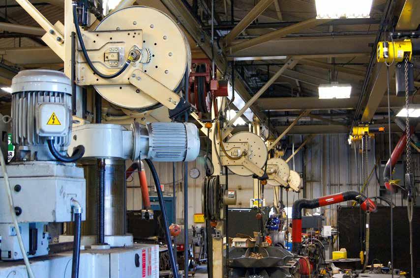
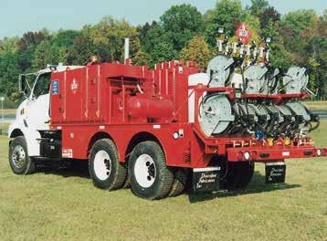
Hannay hose reels come in all sizes and capacities.
Hannay Reels is the leading manufacturer of high quality hose and cable reels for most every conceivable application. This catalog describes and gives specifications on our most popular hose reels. If you don’t see what you’re looking for, give us a call and we will help you meet your needs.
Hannay Reels offers aluminum, carbon and stainless steel construction for most models.
Special coatings and finishes are also available.
Hannay Reels: The industry choice.
Designed to spec and built of the highest quality materials, our reels stand up to the most demanding conditions of any industry. We offer thousands of hose and cable reels that help improve efficiency, productivity, and safety in your operation by keeping hoses and cables organized and off the floor.
The heavy-duty design and construction of our reels ensure that they outlast the competition and save you money. And bolted-on components and conveniently located swivel joints make servicing our reels quick and trouble-free. Every reel we build is created for the industry in which it will be used, from processing to welding to maintenance and more – never retrofitted to the job. That means you can trust Hannay reels to be durable and dependable for years to come.
Uses:
• Blasting/slurry
• Hydraulic/pneumatic power tools
• Washdown and sanitation
• Chemical transfer
•
•
• Pressurized air
• Gas welding
• Fuel and lubrication
• Electric cable for lights, tools, and machinery
• In-plant firefighting
• Vacuum and
C G H Y D E 2 Phone: 518-797-3791 Toll Free: 1-877-467-3357 FAX: 518-797-3259 Email: reels@hannay.com hannay.com
X A F
INDUSTRIAL HOSE REELS CONTENTS
wash/steam cleaning
Power
water
Potable
Reel Type I.D. Hose Sizes Page Hannay Reels Sales Policies 3 Hannay Reels Spec Worksheet 4 Hose Assemblies, Mounting Hole Sizes 5 Spring Rewind Hose Reels Series AG 1/4" – 1-1/2" 6-7 Series N400 1/4" or 3/8" 8 Series N500 (high pressure)* 1/4" or 3/8" 9 Series N600 (dual hose) 1/4" – 1/2" 10 Series 600 (dual hose) 1/4" – 3/4" 11 Series N700* 1/4" – 1/2" 12 Series 700* 1/4" – 1/2" 13 Series N800* 3/4" or 1" 14 Series 800* 3/4" or 1" 15 Series 900* 1-1/4" or 1-1/2" 16 Compact Manual Rewind Hose Reels Series 1000 1/4", 3/8" or 1/2" 17 Manual or Power Rewind Hose Reels Series 1500 3/8" – 5/8" 18 Series 1800 5/8" or 3/4" 19 Series 2000 (dual hose) 1/4" – 1/2" 20 Series G2000 (dual hose, manual only)1/4" – 1/2" 21 Series 3000 (manual only) 3/4" or 1" 22 Series 3500 (manual only) 1-1/4" or 1-1/2" 23 Series 4000 3/4" or 1" 24 Series G4100 3/4" or 1" 25 Series 6000 1/2" – 1" 26-27 Series 7000 (dual hose) 3/4" or 1" 28 Series 7500* 1-1/4" or 1-1/2" 29 Series 8000 1-1/2" or 2" 30 Series 9000 2-1/2" or 3" 31 Portable Hose Reels on Wheels Series 1100, AT1200 3/8" – 1" 32 Portable Storage Reels on Wheels Series C1150, ATC1250 NA 33 Storage Reels: Manual or Power Rewind Series C1500 1/4" – 1" O.D. 34 Series C3200 (manual only) 1/2" – 1-1/2" O.D. 35 Chemical Reels: Manual or Power Rewind Series CHC 3/8" – 1-1/2" I.D. 36 Series SNC (Non-Corrosive) 3/8" – 5/8" I.D. 37 Vacuum Reels: Manual or Spring Rewind Series VAC4000 1-1/4" or 2" I.D. 38 Series VACN900, VAC900, VAC2900 1-1/4" or 2" I.D. 39 * Reel is appropriate for fuel/lubrication applications Page 1
suction
HannayReels SalesPolicies
Hannay Reels 3-Year Limited Warranty
Products manufactured by Hannay Reels, Inc. (“Hannay”) are warrantied for 3 years from date of shipment when properly installed, maintained, and operated in accordance with Hannay instructions. In no event will Hannay have a warranty obligation for normal wear and tear, or for products that have, at Hannay’s determination, been subjected to accident, abuse, misapplication, improper installation or improper maintenance. Common examples of normal wear and tear would include paint finish, swivel joint seal wear, and switch or motor brush wear.
Hannay makes no warranties, express or implied, other than those included in this warranty statement, and we disclaim any implied warrant of merchantability or fitness for any particular purpose. Hannay will not be liable for any consequential, incidental, or indirect damages from any cause whatsoever.
Failure to use a flexible inlet connection on any live hose reel will void the swivel joint warranty. Failure to use a properly sized circuit breaker with any electric rewind motor will void the electric motor warranty. Failure to use a filter and lubricator on any air rewind motor will void the air motor warranty. Failure to follow all procedures outlined in the Safety Guidelines document will void the warranty.
Notice on Reel Finish
Standard finish on Hannay reels is a high performance modified acrylic enamel paint. Standard color is metallic graphite. Other colors available, please consult factory.
Most of the major components on standard reels are e-coated prior to receiving final topcoat paint finish. This combination of e-coat and enamel topcoat will meet the finish requirements of most customer applications and environments.
In cases where requirements cannot be met with the standard finish, Hannay Reels can coat any model reel with an automotive primer, allowing application of final coating at your facility.
Return Goods Policy
All Hannay reels are built to order. These orders are typically placed into production within 1 business day of receipt. Once production begins, it may not be possible to cancel the order.
To prevent returns because the wrong reels or parts were ordered, please use the Hannay Reels Spec Worksheet (either online or from our Order Accessory Guide) when specifying reels. Be sure to include any size, weight, pressure and/or material compatibility limitations for the application.
In the event that an item does need to be returned for credit, repair or replacement, prior approval must be obtained from Hannay Reels. Upon your request, we will send a Return Goods
Components not manufactured by Hannay will be subject to the original manufacturers’ warranties. Examples of such components include: hose and cable, motors, speed controls, and switches, swivel joints and seals, slip ring and brush assemblies.
Equipment which proves to be defective upon our inspection will be replaced free of charge, including freight to the customer. Our responsibility ceases upon delivery to any common carrier and we do not, unless previously instructed, insure shipments beyond point of delivery to such carrier. No material will be accepted for return without a return goods authorization (RGA). This warranty extends to the replacement or repair of the reel or part (no labor).
Hannay reserves the right to modify or alter materials, dimensions, design, and construction when necessary to improve the performance of the reel and/or accessories, or to meet delivery requirements.
Alternatively, Hannay Reels can provide a quote for matching a customer-provided paint specification. For further information, please contact your Hannay Reels sales engineer and a special paint request form will be sent to you.
For environments where no paint finish is suitable, we offer both aluminum and stainless steel (304 grade) construction on most reel models.
Authorization (RGA) form. A signed copy of this form must accompany the material when returned to us, with the RGA number clearly showing on the outside of the box—a label is provided to you that you can print and attach. No product will be accepted for return or credit without an authorized RGA number.
All material must be returned prepaid, unless otherwise noted on our RGA. No return will be accepted that has been damaged due to improper return packaging, tampered with or altered from its original condition. Our restocking and handling fee is a minimum of 25% for standard catalog reels and parts. Custom reels specially built to customer specifications cannot be returned for any reason.
Y D 3 Phone: 518-797-3791 Toll Free: 1-877-467-3357 FAX: 518-797-3259 Email: reels@hannay.com hannay.com INDUSTRIAL HOSE REELS
Page 2
HOW DO I GET THE RIGHT REEL?
HannayReels SpecWorksheet
To specify Hannay reels, fill out this simple form and mail, fax or email it to your dealer. Photocopy this page or download and print from hannay.com
2. What is the reel for?
4. Specifying Location of Components
will be shipped as Right Top Rewind with the inlet, outlet riser, and rewind mechanism on the operator’s right. RT
Right Top Rewind Standard – Always look at your reel from this position to determine right hand or left hand.
3. What features does the reel need? Check type of rewind: MANUAL REWIND
POWER REWIND
5. Please note size and/ o r weight limitations for your installation
X A F C G H Y D E 4 Phone: 518-797-3791 Toll Free: 1-877-467-3357 FAX: 518-797-3259 Email: reels@hannay.com hannay.com
Contact Date / / Company Position Street Address City State Zip Country Phone ( ) Fax ( ) Email or Drag Position SR Lift Position VR Stretch (no roller) Position TR Wall Mount Position TR Recovery (pick-up) (no roller)
1. Who is the reel for?
SPECIFICATIONS Depth: Height: Width: Weight: Indicate your custom specifications CABLE (check one): Live* Storage only *Number of conductors, or wire gauge, required: *Number of connectors: Cable weight: Cable length: *Voltage: Outside diameter: *Amperage (live application only): Bend radius: Note: Use component location initials as suffix after model number (ie: E1520-17-18 LT)
Optional Location of Components: Location of the inlet, outlet riser, and rewind mechanism can be varied to meet your requirements
Unless otherwise specified,
reels
RB – Right Bottom Rewind LT – Left Top Rewind LB – Left Bottom Rewind
custom specifications
and must be specified on your order.
most
–
Indicate your
(hand over hand) Gear-driven crank Direct crank (permanent or
Chain-driven crank
Spring Air Electric (voltage): Hydraulic Type of installation (check one): Floor Wall Overhead Vehicle Temperature Range: Environment: Accessories (if any): Hose/Cable Stop: Yes No Roller Assemblies: Finish: Painted steel (standard) Aluminum Polished Unpolished Stainless steel Polished Unpolished Check type of installation and roller position for spring reels: or or
Disc rewind
removable)
HOSE (check one): Storage only Live Single hose Live Dual hose Inside diameter: Hose length: Bend radius: Flat hose dimensions: Outside diameter: Hose weight: Coupling spacing: Type of product handled live application: (check one): Liquid (specify): Temperature: Oxygen/Acetylene: Other (specify): Gases (specify): Pressure: Hydraulic fluid (specify): Fluid path type: (check one): Steel (standard) Aluminum Stainless Steel Other Reel inlet type: (check one): Swivel joint 90° (standard) Straight Reel outlet type (riser): Size: Thread (check one): National Pipe Thread (NPT) Joint Industry Committee (JIC) Other National Standard Thread (NST) British Standard Pipe (BSP) Page 3
Hose Assemblies
Allow us to quote the hose along with the reel to simplify your procurement process. Hannay inventories a wide variety of hose assemblies for common applications like general purpose air and water, petroleum products, hydraulics, oxygen/acetylene, breathing air, and rescue equipment. Special lengths, fittings, and custom application assemblies are usually available in 5 to 10 business days. Beside the I.D. and Length, be sure to know the Temperature Range, Fluid, Working Pressure, and Fitting Specifications for your hose.
Low Pressure Hose
We stock a variety of low pressure hose assemblies in several sizes and lengths. We offer hose with EPDM cover and tube and brass fittings, which are excellent for air, water, and many agricultural chemicals. EPDM is recommended for outside usage due to its resistance to heat, sunlight, and weathering.
For shop use, we offer a hose with high oil resistant tube and cover. It is suitable for use with petroleum based hydraulic fluid, lubricating oil, anti-freeze, diesel fuel, water, and air and may be special ordered in several different colors. Hoses for specialty applications are available upon request.
Twin Hydraulic Hose
Hannay Reels offers bonded hydraulic hose that helps solve problems associated with unwinding and storing multiple lines. Various options are available not only for hydraulic fluid, but a wide variety of chemicals, agricultural sprays, urethane foam mixers, and fire resistant fluids.
Medium and High Pressure Hose
Several different hydraulic and general purpose hose assemblies are offered to meet the specifications of your particular application. We stock an assortment of common sizes to be able meet your needs with a minimum delivery time.
Twin Oxygen/Acetylene Hose
We stock Grade R and Grade T twin hose assemblies in 1/4" and 3/8" in lengths of 50', 75', and 100' which will cover most requirements for oxygen/acetylene, as well as propane and MAPP. For oxygen/acetylene reels, see the Hannay Welding Reels Catalog H-0408-W.
Note: All spring rewind reels complete with hose are supplied with appropriate hose stop. (See Ordering & Accessory Guide.)
Mounting Hole Sizes
N Series Reels 7/16" wide x 7/8" long slot running front to back
Pressed Frame Reels and Channel Framed Reels
7/16" wide x 7/8" long slot running left to right
Series 1000 7/16" wide x 1 7/16" long slot
Series 1500, 1800, 2000, 4000 13/32" round holes
Y D 5 Phone: 518-797-3791 Toll Free: 1-877-467-3357 FAX: 518-797-3259 Email: reels@hannay.com hannay.com Hose
Complete Reel Packages are also available. For further information, refer to the Reel Packages Sheet at Hannay.com. INDUSTRIAL HOSE REELS
Assemblies
Page 4
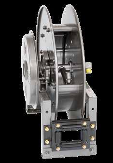
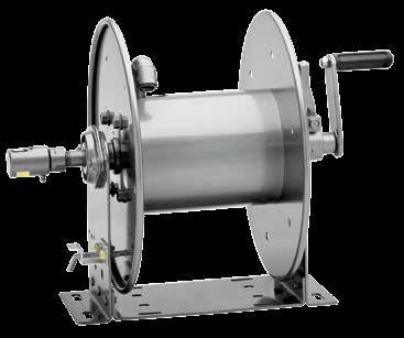
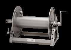
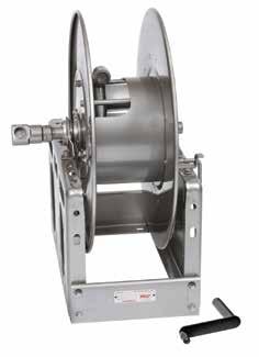
Series AG
To handle 1/4" through 1-1/2" I.D. hose.
Most Hannay spring reel models are available with an air governor rewind assist, which prevents the hose from winding back onto the reel too quickly. Speed is regulated by restricting air flow through an air governor attached to the rewind mechanism. The result is smooth, controlled rewind speed each and every time.
Unlike other speed control mechanisms designed for spring rewind reels, there are 3 major advantages to the Hannay design:
1. Highly scalable – The air speed control governor can be scaled up to regulate speed on even the most powerful spring reels we offer. Other designs can only work on light-duty springs.
2. Operates in all climates – Because the AG Series uses air flow to control speed (not hydraulic fluid, which can change viscosity depending on temperature), the reel’s rewind speed is controlled and unaffected, even by cold weather.
3. Fully adjustable – The end-user can turn the air restrictor clockwise or counterclockwise until the optimal rewind speed is found for the application.
For further information (other than dimensions) on any of the AG Series reels listed below, please go to the following pages in this catalog:
• AG600 Series: Go to page 11 (Series 600)
• AG700 Series: Go to page 13 (Series 700)
• AG800 Series: Go to page 15 (Series 800)
• AG900 Series: Go to page 16 (Series 900)
C G H Y
E 6 Phone: 518-797-3791 Toll Free: 1-877-467-3357 FAX: 518-797-3259 Email: reels@hannay.com hannay.com SPRING REWIND REELS
X A F
D
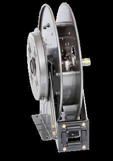
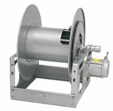
AG800 Series Standard SR configuration shown
Page 5
With Air Speed Control Governor
Notes:
A hose stop is necessary to keep spring from unwinding.
1. Specifications subject to change.
2. Reel models and capacities shown are for standard drag applications; for vertical lift applications, consult factory.
Available Roller Positions
With Air Speed Control Governor
Series AG
3. Other sizes, from standard components, available on request.
4. Finish: Refer to page 3.
5. Be sure to check dimensions and weights prior to ordering.
NOTICE: A flexible connector must be used between the inlet pipe and the inlet swivel joint. *** X, Y indicate mounting holes. See page 5.
SR (STD) VR (OPT) TR (OPT) TR (Wallmount)
Y D 7 Phone: 518-797-3791 Toll Free: 1-877-467-3357 FAX: 518-797-3259 Email: reels@hannay.com hannay.com
REWIND
SPRING
REELS
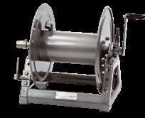
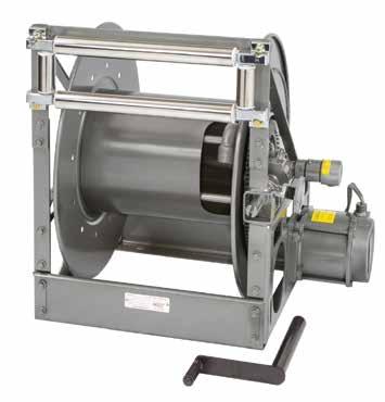
B C X A F Y D G H E AG800 shown
Model Number Hose Capacity of Reel feet m Approx. Weight lb. kg Std. Roller Assy. Reel Dimensions*** in. mm I.D. in. 1/43/81/23/4 1 1-1/41-1/2 NETSHIP ABCDEFGHXY mm 6 101319253238 O.D. in. 5/83/47/8 1-9/321-9/16 1-13/16 2-1/16 mm16192233404652 AG615-23-24-10.5B 2/652/60 2/30 117 152 AG303 9.25 3 10.5 25.25 22.75 16 23.88 12.5 4.5 20 2/20 2/18 2/9 53 69 235 76 267 641 578 406 607 318 114 508 AG617-25-26-15.5B 2/752/752/50 118 153 AG305 11.255 15.5 27 24.75 18 25.88 13.5 6.5 21.75 2/232/23 2/15 54 69 286 127 394 686 629 457657 343 165 552 AG617-25-26-15.5A 2/1002/85 145 180 AG305 11.255 15.5 27 24.7518.75 25.88 13.5 6.5 21.75 2/30 2/26 –––––66 82 286 127 394 686 629 476 657 343 165 552 AG618-30-31-15.5A 2/100 2/50 155190 AG306 12.25 6 15.5 30.5 28.7519.75 31.38 17 7.5 25.25 2/30 2/15 70 86 311 153 394 775 730 502 797 432 190 641 AG716-19-20-10.5J – 5050 101 136 AG304 10.25 4 10.5 20.5 18.7514.75 20 10.62 5.5 14.75 – 1515 46 62 260 102 267 521 22.75 375 508 270 139 375 AG716-23-24-15.5J – 6565 111 146 AG304 10.25 4 15.5 25.25 24.7514.75 23.88 12.5 5.5 20 – 2020 50 66 260 102 394 641 629 375 607 318 139 508 AG716-25-26-15.5B – 7575 115 150 AG304 10.25 4 15.5 27 24.7514.75 25.88 13.5 5.5 21.75 – 2323 52 68 260 102 394 686 629 375 657 343 139 552 AG718-25-26-15.5G – 100100 121 156 AG306 12.25 6 15.5 27 24.7516.75 25.88 13.5 7.5 21.75 – 3030 55 71 311 152 394 686 629 425 657 343 190 552 AG718-30-31-20D – 150 125–––– 152 187 AG306 12.25 6 20 30.5 28.7516.75 31.38 17 7.5 25.25 – 4638 69 85 311 152 508 775 730 425 797 432 190 641 AG818-23-24-10.5J 50 25–– 110 145 AG306 12.25 6 10.5 25.25 22.7516.75 23.88 12.5 7.5 20 15 8–– 50 66 311 152 267 641 578 425 607 318 190 508 AG816-25-26-10.5B 60 35 121 156 AG304 10.25 4 10.5 27 24.7514.75 25.88 13.5 5.5 21.75 18 11 55 71 260 102 267 686 629 375 657 343 140 552 AG818-25-26-10.5B 70 50 127 162 AG306 12.25 6 10.5 27 24.7516.75 25.88 13.5 7.5 21.75 21 15 58 73 311 152 267 686 629 425 657 343 190 552 AG820-25-26-10.5A 85 75 156 191 AG308 14.25 8 10.5 27 24.75 19.5 25.88 13.5 9.5 21.75 2623 71 87 362204 267 686 629 495 657 434 241 552 AG820-30-31-10.5A 100 162 197 AG308 14.25 8 10.5 30.5 28.75 19.5 31.38 17 9.5 25.25 30 73 89 362204 267 775 730 495 797 432 241641 AG820-30-31-15.5A 100 170 205 AG308 14.25 8 15.5 30.5 28.75 19.5 31.38 17 9.5 25.25 30 77 93 362204 394 775 730 495 797 432 241641 AG920-25-26-10.5A 50 40 152 187 AG308 14.25 8 10.5 27 24.75 24 25.88 13.5 9.5 21.75 15 12 69 85 362204 267 686 629 610 657 343 241 552 AG922-30-31-10.5A 75 50 181 216 AG310 16.25 1010.5 30.5 28.75 26 31.38 17 11.5 25.25 23 15 82 98 413 254 267 775 730 660 797 432 292 641 Page 6
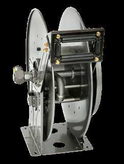
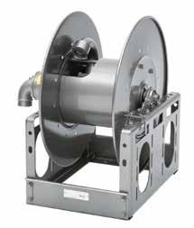
Series N400
• Gas Welding
To handle twin 1/4" or 3/8" I.D. welding hose.
• Heavy-duty spring motor.
• Non-sparking ratchet assembly.
• Declutching arbor to prevent damage from reverse winding.
• Standard inlets: 90° ball bearing swivel joints, 1/2" female NPT threads.
• Standard outlets: male 9/16"-18 threads, right-hand for oxygen, lefthand for gas.
• Pressures to 300 psi (21 bar).
• Standard fluid temperatures from -15° F to +250 °F (-26° C to +121° C). Optional temperature ratings available - consult factory.
• Type of gas used MUST be specified.
• Hose stop is required.
• 4-way roller assembly. SR position is standard, other configurations available, must specify.
X A F
PARTS DRAWING – ISO 186
Notes:
A hose stop is necessary to keep spring from unwinding.
1. Specifications subject to change.
2. Reel models and capacities shown are for standard drag applications; for vertical lift applications, consult factory.
3. Other sizes, from standard components, available on request.
4. Finish: Refer to page 3.
5. Be sure to check dimensions and weights prior to ordering.
NOTICE: A flexible connector must be used between the inlet pipe and the inlet swivel joint.
* When shipped as a parcel package (via FedEx or UPS Ground), joints loose. Net weight plus carton weight.
*** X, Y indicate mounting holes. See page 5.
C G H
E 8 Phone: 518-797-3791 Toll Free: 1-877-467-3357 FAX: 518-797-3259 Email: reels@hannay.com hannay.com
Y D
SPRING REWIND REELS
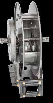
Standard
B C X A F G H E Y 10 254 D 12 305
SR configuration shown
SR (STD) VR (OPT) TR (OPT) TR (Wallmount) Available Roller Positions
Model Number Hose Capacity of Reel feet m Approx. Weight lb. kg Standard Roller Assy. Reel Dimensions*** in. mm I.D. in. 1/4 3/8 NET SHIP ABCEFGHX mm 69 O.D. in. .53.66 mm 13 17 N416-17-18-8L 2/50 – 64 69* N204 10 4 8 19.5 15 17.38 9.13 8 2/15 – 29 31 254 102 203 495 381 441 232 203 N416-19-20-8L – 2/50 68 74* N204 10 4 8 20.75 15 20 10.62 8 – 2/15 31 34 254 102 203 527 381 508 270 203 N416-19-20-10.5C 2/25 2/25 70 77* N204 10 4 10.5 20.75 15 20 10.62 8 2/8 2/8 32 35 254 102 267 527 381 508 270 203 N416-19-20-8J 2/50 2/50 74 80* N204 10 4 8 20.75 15 20 10.62 8 2/15 2/15 34 36 254 102 203 527 381 508 270 203 N417-23-24-10.5G 2/75 2/75 94 111* N205 11 5 10.5 24 16 24 12.62 9 2/23 2/23 43 50 279 127 267 610 406 610 320 229 N417-25-26-10.5G 2/100 2/100 97 132 N205 11 5 10.5 25.5 16 26 13.62 9 2/302/30 43 52 279 127 267 648 406 660 346 229 Page 7
To handle single 1/4" or 3/8" I.D. hose.
• Compact frame and narrow base.
• Non-sparking ratchet assembly.
• Declutching arbor to prevent damage from reverse winding.
• Standard inlet: 90° swivel joint, 1/4" female NPT threads.
3/8" female NPT threads are optional and must be specified.
• Standard outlet: 1/4" female NPT threads.
3/8" female NPT threads are optional and must be specified.
• Other threads can be furnished and must be specified.
• Standard 1/4" pressure 10,000 psi (690 bar); Standard 3/8" pressure: 3000 psi (207 bar).
Optional 3/8" pressure: 8000 psi (552 bar) – must specify.
• Standard fluid temperatures from -40° F to +250 °F (-40° C to +121° C). Optional temperature ratings available - consult factory.
• 4-way roller assembly. SR and VR roller positions: swivel joint is standard on the right. TR roller positions: swivel joint is standard on the left. Other configurations available, must specify.
• Constant tension is available – consult factory.
SPRING
Notes:
A hose stop is necessary to keep spring from unwinding.
1. Specifications subject to change.
2. Reel models and capacities shown are for standard drag applications; for vertical lift applications, consult factory.
3. Other sizes, from standard components, available on request.
4. Finish: Refer to page 3.
Available Roller Positions
5. Be sure to check dimensions and weights prior to ordering.
NOTICE: A flexible connector must be used between the inlet pipe and the inlet swivel joint.
* Dimensional weight may apply when shipped as a parcel package (via FedEx or UPS Ground).
*** X, Y indicate mounting holes. See page 5.
Optional Swivel Mounting Bracket

Part No. 9908.9990.
For N-Series spring retractable reels, available as a kit. Conditions apply, consult factory.
Y D 9 Phone: 518-797-3791 Toll Free: 1-877-467-3357 FAX: 518-797-3259 Email: reels@hannay.com hannay.com Series N500 • Chassis Grease • Hydraulics • Air/Water
B C X A F G H E Y 10 254 D 12 305 SR (STD) VR (OPT) TR (OPT) TR (Wallmount)
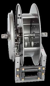
Standard SR configuration shown with optional full-flow swivel joint
High Pressure
PARTS DRAWING – ISO 92 Model Number Hose Capacity of Reel feet m Approx. Weight lb. kg Standard Roller Assy. Reel Dimensions*** in. mm I.D. in. 1/4 3/8 NET UPS/ FedEx SHIP Wt. Freight SHIP Wt. ABCEFGHX mm 6 10 O.D. in. 5/8 3/4 mm1619 N515-14-16-8L 2525 48 64* 83 N203 938 18.12 10.38 16.12 9.12 7 88 22 29 38 229 76 203 460 264 409 232 178 N515-16-17-10.5C 3535 51 67* 86 N203 93 10.5 19 10.38 17 9.12 7 111123 30 39 229 76 267 483 264 432232 178 N515-19-20-10.5J 5050 63 81* 98 N203 93 10.5 20.7510.38 20 10.62 7 1515 29 37 44 229 76 267 527 264 508 270 178 N515-23-24-15.5J 75 65 75 92* 110 N203 93 15.5 24 10.38 24 12.62 7 23 20 34 42 50 229 76 394 610 264 610 321 178 N516-25-26-15.5B 7575 90 125 N204 10 4 15.525.5 11.38 26 13.62 8 2323 34 57 254 102 394 648 289 660 346 203
REWIND REELS Page 8
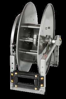
Series N600
Dual Hose
• Hydraulics • Spray Painting • Air/Water
To handle dual 1/4" through 1/2" I.D. hose.
• Narrow frame and compact mounting base.
• Non-sparking ratchet assembly.
• Declutching arbor to prevent damage from reverse winding.
• Standard inlets: 90° full-flow swivel joints with Viton® seals, 1/2" female NPT threads.
• Optional balanced pressure (BP) swivel joints are available upon request. Subtract 1-3/4" from “F” dimension.
• Standard outlets: 1/2" female NPT threads.
• Standard pressures to 3000 psi (207 bar), available up to 10,000 psi (690 bar) – must specify.
• Standard fluid temperatures from -15° F to +250 °F (-26° C to +121° C). Optional temperature ratings available - consult factory.
• 4-way roller assembly. SR position is standard, other configurations available, must specify.
• Constant tension is available – consult factory.
• Reels for use with oxygen/acetylene. See Series N400 on page 8.
– ISO 80
Notes:
A hose stop is necessary to keep spring from unwinding.
1. Specifications subject to change.
2. Reel models and capacities shown are for standard drag applications; for vertical lift applications, consult factory.
3. Other sizes, from standard components, available on request.
4. Finish: Refer to page 3.
Available Roller Positions
5. Be sure to check dimensions and weights prior to ordering.
NOTICE: A flexible connector must be used between the inlet pipe and the inlet swivel joint.
*Dimensional weight may apply when shipped as a parcel package (via FedEx or UPS Ground).
*** X, Y indicate mounting holes. See page 5. For hydraulic tool circuit applications, full flow swivels with Viton® seals are recommended.
C G
E 10 Phone: 518-797-3791 Toll Free: 1-877-467-3357 FAX: 518-797-3259 Email: reels@hannay.com hannay.com
X A F
H Y D
B C X A F G H E Y 10 254 D 12 305 PARTS DRAWING
Model Number Hose Capacity of Reel feet m Approx. Weight lb. kg Standard Roller Assy. Reel Dimensions*** in. mm I.D. in. 1/4 3/8 1/2 NET UPS/ FedEx SHIP Wt. Freight SHIP Wt. ABCEF Full-Flow F BP GHX mm 6 1013 O.D. in. 5/8 3/4 7/8 mm161922 N615-19-20-10.5C 2/352/35 2/20 63 74* 98 N203 93 10.5 20.75 1412.25 20 10.62 7 2/112/11 2/6 29 34 44 229 76 267 527 356 311 508 270 178 N617-19-20-10.5J 2/502/50 2/25 66 84* 101 N205 11 5 10.5 20.75 16 14.25 20 10.62 9 2/152/15 2/8 30 3846 279 127 267 527 406 362 508 270 229 N615-23-24-10.5B 2/652/60 2/30 87 104* 122 N203 93 10.5 24 1412.25 24 12.62 7 2/20 2/18 2/9 40 47 55 229 76 267 610 356 311 610 321 178 N617-25-26-15.5B 2/752/752/50 93 – 128 N205 11 5 15.525.5 16 14.25 26 13.62 9 2/232/23 2/15 42 – 58 279 127 394 648 406 362 660 346 229 N617-25-26-15.5A 2/1002/85 – 120 – 155 N205 11 5 15.525.5 16.75 15 26 13.62 9 2/31 2/26 – 54 – 70 279 127 394 648 425 381 660 346 229
SR (STD) VR (OPT) TR (OPT) TR (Wallmount)
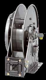
Standard SR configuration shown
Page 9
SPRING REWIND REELS
SPRING REWIND REELS
Dual Hose
To handle dual 1/4" through 3/4" I.D. hose.
• Rollformed channel frame for heavy-duty applications.
• Non-sparking ratchet assembly.
• Declutching arbor to prevent damage from reverse winding.
• Standard inlets: 90° full-flow swivel joints with Viton® seals, 1/2" female NPT threads (1" inlet available). Must be specified.
• Optional balanced pressure (BP) swivel joints are available upon request. Subtract 1-3/4" from “F” dimension.
• Standard outlets: 1/2" female NPT threads (3/4" outlet available). Must be specified.
• Standard pressures to 3000 psi (207 bar), available up to 10,000 psi (690 bar) – must specify.
• Standard fluid temperatures from -15° F to +250 °F (-26° C to +121° C). Optional temperature ratings available - consult factory.
• 4-way roller assembly. SR position is standard, other configurations available, must specify.
• Constant tension is available – consult factory.
• Reels for use with oxygen/acetylene.
See Series N400 on page 8.
PARTS DRAWING – ISO 8
Notes:
A hose stop is necessary to keep spring from unwinding.
1. Specifications subject to change.
2. Reel models and capacities shown are for standard drag applications; for vertical lift applications, consult factory.
3. Other sizes, from standard components, available on request.
4. Finish: Refer to page 3.
5. Be sure to check dimensions and weights prior to ordering.
NOTICE: A flexible connector must be used between the inlet pipe and the inlet swivel joint. ***X, Y indicate mounting holes. See page 5.
† Must specify if 1" joints and 3/4" outlet risers are required.
For hydraulic tool circuit applications, full flow swivels with Viton® seals are recommended.
Y D 11 Phone: 518-797-3791 Toll Free: 1-877-467-3357 FAX: 518-797-3259 Email: reels@hannay.com hannay.com Series 600 • Hydraulics • Spray Painting • Air/Water
B C X A F Y D G H E
Model Number Hose Capacity of Reel feet m Approx. Weight lb. kg Standard Roller Assy. Reel Dimensions*** in. mm I.D. in. 1/4 3/8 1/2 3/4 NETSHIP ABCDEF Full-Flow F BP GHXY mm 6 101319 O.D. in. 5/8 3/4 7/8 1-9/32 mm16192233 615-23-24-10.5B 2/652/60 2/30 – 70 105 R203 8.25 3 10.5 24.62 22.75 15 13.3823.88 12.5 3.5 20 2/20 2/18 2/9 – 32 48 210 76 267 625 578 381 340 607 318 89 508 617-25-26-15.5B 2/752/752/50 – 93 128 R205 10.25 5 15.5 26.38 24.75 17 15.3825.88 13.5 5.5 21.75 2/232/23 2/15 – 42 58 260 127 394 670 629 432 391 657 343 140 552 617-25-26-15.5A 2/1002/85 120 155 R205 10.25 5 15.5 26.38 24.75 17.75 16.06 25.88 13.5 5.5 21.75 2/31 2/26 54 70 260 127 394 670 629 451 408 657 343 140 552 † 618-30-31-15.5A 2/100 2/50 130 165 R206 11.25 6 15.5 29.88 28.7518.75 17.06 31.38 17 6.5 25.25 2/31 2/15 59 75 286 152 394 759 730 476 433 797 432 165 641
SR (STD) VR (OPT) TR (OPT) TR (Wallmount)
Standard SR configuration shown
Available Roller Positions
Page 10
SPRING REWIND REELS
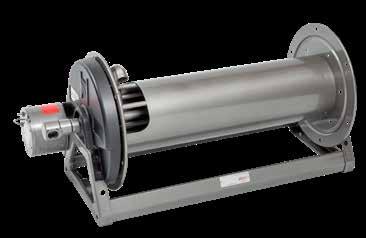
Series N700
•
Lubrication • Air/Water • Assembly Operations
• Washdown • Air Tools • General Industrial Applications
To handle 1/4" through 1/2" I.D. hose.
• Narrow frame and compact mounting base.

• Non-sparking ratchet assembly.
• Declutching arbor to prevent damage from reverse winding.
• Standard inlet: 90° balanced pressure swivel joint, 1/2" female NPT threads.
• Standard outlet: 1/2" female NPT threads.
• Standard pressures to 3000 psi (207 bar), available up to 10,000 psi (690 bar) – must specify.
• Standard fluid temperatures from -40° F to +250 °F (-40° C to +121° C). Optional temperature ratings available - consult factory.
• 4-way roller assembly. SR and VR roller positions: swivel joint is standard on the right. TR roller positions: swivel joint is standard on the left. Other configurations available, must specify.
• Constant tension is available – consult factory.
PARTS DRAWING – ISO 79
Notes:
A hose stop is necessary to keep spring from unwinding.
1. Specifications subject to change.
2. Reel models and capacities shown are for standard drag applications; for heavy-duty or vertical lift applications, consult factory.
3. Other sizes, from standard components, available on request.
4. Finish: Refer to page 3.
5. Be sure to check dimensions and weights prior to ordering.
Available Roller Positions
NOTICE: A flexible connector must be used between the inlet pipe and the inlet swivel joint.
*Dimensional weight may apply when shipped as a parcel package (via FedEx or UPS Ground).
***X, Y indicate mounting holes. See page 5.
†Capacity based on low pressure air hose only. Not for vertical lift applications.
††SD spring to be used for heavy-duty or vertical lift applications, consult factory.
Optional Swivel Mounting Bracket
Part No. 9908.9990. For N-Series spring retractable reels, available as a kit. Conditions apply, consult factory.
C G
E 12 Phone: 518-797-3791 Toll Free: 1-877-467-3357 FAX: 518-797-3259 Email: reels@hannay.com hannay.com
X A F
H Y D
B C X A F G H E Y 10 254 D 12 305
Standard SR configuration shown
Model Number Hose Capacity of Reel feet m Approx. Weight lb. kg Standard Roller Assy. Reel Dimensions*** in. mm I.D. in. 1/4 3/8 1/2 NET UPS/ FedEx SHIP Wt. Freight SHIP Wt. ABCEFGHX mm 6 1013 O.D. in. 5/8 3/4 7/8 mm161922 N716-14-16-8C – 2525 52 64* 87 N204 10 48 18.12 11.63 16.12 9.12 8 –88 24 2939 254 102 203 460 295 409 232 203 N716-16-17-10.5C – 353555 69* 90 N204 10 4 10.5 19 11.63 17 9.12 8 – 1111 25 31 41 254 102 267 483 295 432232 203 †N716-17-18-8L – 50† 50† 55 68* 90 N204 10 48 19.5 11.63 17.38 9.12 8 – 15† 15† 25 31 41 254 102 203 495 295 441 232 203 N716-19-20-10.5J – 5050 64 82* 99 N204 10 4 10.5 20.75 11.63 20 10.62 8 – 1515 29 37 45 254 102 267 527 295 508 270 203 N716-23-24-15.5J – 6565 79 94* 114 N204 10 4 15.5 24 11.63 24 12.62 8 – 2020 36 43 52 254 102 394 610 295 610 321 203 N716-23-24-15.5G 100 75 65 94 101* 129 N204 10 4 15.5 24 11.63 24 12.62 8 30 23 20 43 46 59 254 102 394 610 295 610 321 203 N716-25-26-15.5B – 7575 90 – 125 N204 10 4 15.525.5 11.63 26 13.62 8 – 2323 41 – 57 254 102 394 648 295 660 346 203 N718-25-26-15.5G – 100100 96 – 131 N206 12 6 15.525.5 13.63 26 13.62 10 – 3030 44 – 59 305 152 394 648 346 660 346 254 ††N718-25-26-15.5 SD – 100100104 – 139 N206 12 6 15.525.5 14.38 26 13.62 10 – 3030 47 – 63 305 152 394 648 365 660 345 254
SR (STD) VR (OPT) TR (OPT) TR (Wallmount)
Page 11
To handle 1/4" through 1/2" I.D. hose.
• Rollformed channel frame for heavy-duty applications.
• Non-sparking ratchet assembly.
• Declutching arbor to prevent damage from reverse winding.
• Standard inlet: 90° balanced pressure swivel joint, 1/2" female NPT threads.
• Standard outlet: 1/2" female NPT threads.
• Standard pressures to 3000 psi (207 bar), available up to 10,000 psi (690 bar) – must specify.
• Standard fluid temperatures from -40° F to +250 °F (-40° C to +121° C). Optional temperature ratings available - consult factory.
• 4-way roller assembly. SR and VR roller positions: swivel joint is standard on the right. TR roller positions: swivel joint is standard on the left. Other configurations available, must specify.
• Constant tension is available – consult factory.
PARTS DRAWING – ISO 66
Notes:
A hose stop is necessary to keep spring from unwinding.
1. Specifications subject to change.
2. Reel models and capacities shown are for standard drag applications; for heavy-duty or vertical lift applications, consult factory.
3. Other sizes, from standard components, available on request.
4. Finish: Refer to page 3.
5. Be sure to check dimensions and weights prior to ordering.
NOTICE: A flexible connector must be used between the inlet pipe and the inlet swivel joint.
*Dimensional weight may apply when shipped as a parcel package (via FedEx or UPS Ground).
*** X, Y indicate mounting holes. See page 5. †SD spring to be used for heavy-duty or vertical lift applications, consult factory.
Y D 13 Phone: 518-797-3791 Toll Free: 1-877-467-3357 FAX: 518-797-3259 Email: reels@hannay.com hannay.com • Lubrication • Air/Water • Assembly Operations • Washdown • Air Tools • General Industrial Applications Series 700
SR (STD) VR (OPT) TR (OPT) TR (Wallmount) Available Roller Positions B C X A F Y D G H E
Model Number Hose Capacity of Reel feet m Approx. Weight lb. kg Standard Roller Assy. Reel Dimensions*** in. mm I.D. in. 1/43/8 1/2 NET UPS/ FedEx SHIP Wt. Freight SHIP Wt. ABCDEFGHXY mm 6 1013 O.D. in. 5/83/4 7/8 mm161922 716-23-24-15.5J – 6565 79 92* 114 R204 9.25 4 15.5 24.5 22.75 12.62 23.88 12.5 4.5 20 – 2020 36 42 52 235 102 394 622 578 321 607 318 114 508 716-23-24-15.5G 100 75 65 94 – 129 R204 9.25 4 15.5 24.5 22.75 12.62 23.88 12.5 4.5 20 30 23 20 43 – 59 235 102 394 622 578 321 607 318 114 508 716-25-26-15.5B – 7575 90 – 125 R204 9.25 4 15.5 26.25 24.75 12.62 25.88 13.5 4.5 21.75 – 2323 41 – 57 235 102 394 667 629 321 657 343 114 552 718-25-26-15.5G – 100100 96 – 131 R206 11.25 6 15.5 26.25 24.75 14.62 25.88 13.5 6.5 21.75 – 3030 44 – 59 286 152 394 667 629 371 657 343 165 552 †718-25-26-15.5 SD – 100100 98 – 133 R206 11.25 6 15.5 26.25 24.75 15.3825.88 13.5 6.5 21.75 – 3030 44 – 60 286 152 394 667 629 391 657 343 165 552 718-30-31-20D – 150 125 127– 162 R206 11.25 6 20 30.5 28.75 15.38 31.38 17 6.5 25.25 – 463858 – 73 286 152 508 775 730 391 797 432 165 641
REWIND REELS Page 12
Standard SR configuration shown
SPRING
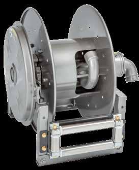
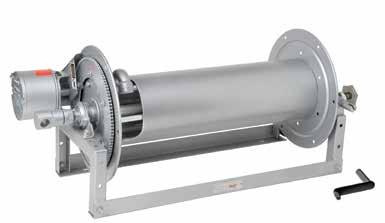
Series N800 SPRING REWIND REELS
• Fuel Dispensing (Consult Factory)
• Waste Oil Evacuation • Air/Water
To handle 3/4" or 1" I.D. hose.
• Narrow frame and compact mounting base.
• Non-sparking ratchet assembly.
• Declutching arbor to prevent damage from reverse winding.
• Standard inlet: 90° balanced pressure swivel joint, 1" female NPT threads.
• Standard outlet: 1" female NPT threads.
• Standard pressures to 2000 psi (138 bar), available up to 6000 psi (414 bar) – must specify.
• Standard fluid temperatures from -40° F to +250 °F (-40° C to +121° C). Optional temperature ratings available - consult factory.
• 4-way roller assembly. SR and VR roller positions: swivel joint is standard on the right. TR roller positions: swivel joint is standard on the left. Other configurations available, must specify.
• Constant tension is available – consult factory.
Notes:
A hose stop is necessary to keep spring from unwinding.
1. Specifications subject to change.
2. Reel models and capacities shown are for standard drag applications; for vertical lift applications, consult factory.
3. Other sizes, from standard components, available on request.
4. Finish: Refer to page 3.
Available Roller
Positions
5. Be sure to check dimensions and weights prior to ordering.
NOTICE: A flexible connector must be used between the inlet pipe and the inlet swivel joint. *Dimensional weight may apply when shipped as a parcel package (via FedEx or UPS Ground). *** X, Y indicate mounting holes. See page 5. †Capacity based on low pressure air hose only.
C G H Y
E 14 Phone: 518-797-3791 Toll Free: 1-877-467-3357 FAX: 518-797-3259 Email: reels@hannay.com hannay.com
X A F
D
B C X A F G H E Y 10 254 D 12 305 PARTS DRAWING – ISO 81 Model Number Hose Capacity of Reel feet m Approx. Weight lb. kg Standard Roller Assy. Reel Dimensions*** in. mm I.D. in. 3/4 1 NET UPS/ FedEx SHIP Wt. Freight SHIP Wt. ABCEFGHX mm1925 O.D. in. 1-9/32 1-1/2 mm3338 N816-19-20-10.5J 25 15 75 83* 110 N204 10 4 10.5 20.75 13 20 10.62 8 85 3438 50 254 102 267 527 330 508 270 203 † N818-23-24-10.5J 50† 25† 87 – 122 N206 12 6 10.5 24 15 24 12.62 10 15† 8† 39 – 55 305 152 267 610 381 610 321 254 N816-25-26-10.5B 50 35 96 – 131 N204 10 4 10.5 25.5 13 26 13.62 8 18 11 44 – 59 254 102 267 648 330 660 346 203 N818-25-26-10.5B – 50 102 – 137 N206 12 6 10.5 25.5 15 26 13.62 10 – 15 46 – 62 305 152 267 648 381 660 346 254 †N818-25-26-10.5G 75 – 108 – 143 N206 12 6 10.5 25.5 15 26 13.62 10 23 – 49 – 65 305 152 267 648 381 660 346 254 N818-25-26-10.5 SD 75 – 110 – 145 N206 12 6 10.5 25.5 15.75 26 13.62 10 23 – 46 – 66 305 152 267 648 381 660 346 254
SR (STD) VR (OPT) TR (OPT) TR (Wallmount)
Optional TR configuration shown Page 13
To handle 3/4" or 1" I.D. hose.
• Rollformed channel frame for heavy-duty applications.
• Non-sparking ratchet assembly.
• Declutching arbor to prevent damage from reverse winding.
• Standard inlet: 90° balanced pressure swivel joint, 1" female NPT threads.
• Standard outlet: 1" female NPT threads.
• Standard pressures to 2000 psi (138 bar), available up to 6000 psi (414 bar) – must specify.
• Standard fluid temperatures from -40° F to +250 °F (-40° C to +121° C). Optional temperature ratings available - consult factory.
• 4-way roller assembly. SR and VR roller positions: swivel joint is standard on the right. TR roller positions: swivel joint is standard on the left. Other configurations available, must specify.
• Constant tension is available – consult factory.
PARTS DRAWING – ISO 42
Notes:
A hose stop is necessary to keep spring from unwinding.
1. Specifications subject to change.
2. Reel models and capacities shown are for standard drag applications; for vertical lift applications, consult factory.
3. Other sizes, from standard components, available on request.
4. Finish: Refer to page 3.
Available Roller Positions
5. Be sure to check dimensions and weights prior to ordering.
NOTICE: A flexible connector must be used between the inlet pipe and the inlet swivel joint. *** X, Y indicate mounting holes. See page 5. †Capacity based on low pressure air hose only.
Y D 15 Phone: 518-797-3791 Toll Free: 1-877-467-3357 FAX: 518-797-3259 Email: reels@hannay.com hannay.com • Fuel Dispensing (Consult Factory) • Waste Oil Evacuation • Air/Water Series 800
B C X A F Y D G H E
Model Number Hose Capacity of Reel feet m Approx. Weight lb. kg Standard Roller Assy. Reel Dimensions*** in. mm I.D. in. 3/4 1 NETSHIP ABCDEFGHXY mm1925 O.D. in. 1-9/32 1-1/2 mm3338 † 818-23-24-10.5J 50† 25† 87 122 R206 11.25 6 10.5 24.5 22.75 15.62 23.88 12.5 6.5 20 15† 8† 39 55 286 152 267 622 578 397 607 318 165 508 816-25-26-10.5B 50 35 96 131 R204 9.25 4 10.5 26.25 24.75 13.62 25.88 13.5 4.5 21.75 18 11 44 59 235 102 267667 629 346 657 343 114 552 818-25-26-10.5B – 50 102 137 R206 11.25 6 10.5 26.25 24.75 15.62 25.88 13.5 6.5 21.75 – 15 46 62 286 152 267667 629 397 657 343 165 552 818-25-26-10.5 SD 75 – 110 145 R206 11.25 6 10.5 26.25 24.75 16.38 25.88 13.5 6.5 21.75 23 – 46 66 286 152 267667 629 416 657 343 165 552 820-25-26-10.5A – 75 131 166 R308 13.25 8 10.5 27 24.75 18.38 25.88 13.5 8.5 21.75 – 23 59 75 337 203 267 686 629 467 657 343 216 552 820-30-31-10.5A – 100 137 172 R308 13.25 8 10.5 30.5 28.75 18.38 31.38 17 8.5 25.25 – 30 62 78 337 203 267 775 730 467 797 432 216 641 820-30-31-15.5A 100 – 145 180 R308 13.25 8 15.5 30.5 28.75 18.38 31.38 17 8.5 25.25 30 – 66 82 337 203 394 775 730 467 797 432 216 641
SR (STD) VR (OPT) TR (OPT) TR (Wallmount)
SPRING REWIND REELS Page 14
Standard SR configuration shown
Series 900
• Bulk Transfer • Fuel Dispensing (Consult Factory)
• Suction/Discharge (Consult Factory)
To handle 1-1/4" or 1-1/2" I.D. hose.
• Rollformed channel frame construction.
• Non-sparking ratchet assembly.
• Declutching arbor to prevent damage from reverse winding.
• Standard inlet: 90° swivel joint, 1-1/2" female NPT threads, and 2" Victaulic® groove.
• Standard outlet: 1-1/2" female NPT threads.
• Standard pressures to 1000 psi (41 bar).
• Standard fluid temperatures from -20° F to +212 °F (-29° C to +100° C). Optional temperature ratings available - consult factory.
• 4-way roller assembly. SR and VR roller positions: swivel joint is standard on the right. TR roller positions: swivel joint is standard on the left. Other configurations available, must specify.
• Constant tension is available – consult factory.
Notes:
A hose stop is necessary to keep spring from unwinding.
1. Specifications subject to change.
2. Reel models and capacities shown are for standard drag applications; for vertical lift applications, consult factory.
3. Other sizes, from standard components, available on request.
4. Finish: Refer to page 3.
Available Roller Positions
5. Be sure to check dimensions and weights prior to ordering.
NOTICE: A flexible connector must be used between the inlet pipe and the inlet swivel joint. *** X, Y indicate mounting holes. See page 5.
C G
D E 16 Phone: 518-797-3791 Toll Free: 1-877-467-3357 FAX: 518-797-3259 Email: reels@hannay.com hannay.com
X A F
H Y
SPRING
REELS
REWIND
SR (STD) VR (OPT) TR (OPT) TR (Wallmount)
B C 10.5 267 X A F Y D G H E PARTS DRAWING – ISO 29 Model Number Hose Capacity of Reel feet m Approx. Weight lb. kg Standard Roller Assy. Reel Dimensions*** in. mm I.D. in. 1-1/41-1/2 NETSHIP ABDEFGHXY mm3238 O.D. in. 1-13/162-1/16 mm4652 922-23-24-10.5B 40 25 104 139 R310 15.25 10 25.25 22.75 24 23.88 12.5 10.5 20 12 8 47 63 387 254 641 22.75 610 607 318 267 508 920-25-26-10.5A 50 40 127 162 R308 13.25 827 24.7522.75 25.88 13.5 8.5 21.75 15 12 58 73 337 203 686 629 578 657 343 216 552 922-30-31-10.5A 75 50156 191 R310 15.25 10 30.5 28.75 24.75 31.38 17 10.5 25.25 23 15 71 87 387 254 775 730 629 797 432 267 641 Standard SR configuration shown Page 15
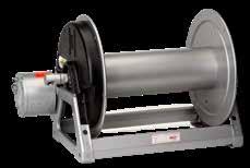
To handle single 1/4", 3/8" or 1/2" I.D. hose.
• Lightweight, compact with an e-coated frame.
• Direct crank rewind permanently attached.
• Adjustable cam-lock brake standard.
• Exterior mounting holes for easier installation.
• Redesigned (and field installable) pin lock.
• Standard inlet: 90° ball bearing swivel joint, 1/2" female NPT threads.
• Standard outlet: 3/8" female NPT threads, 1/2" available upon request.
• Standard pressures to 3000 psi (207 bar), available up to 5,000 psi (345 bar) – must specify.
• Standard fluid temperatures from -32° F to +400 °F (0° C to +204° C). Optional temperature ratings available - consult factory.
Notes:
1. Specifications subject to change.
2. Other sizes, from standard components, available on request.
3. Finish: Refer to page 3.
4. Be sure to check dimensions and weights prior to ordering.
NOTICE: A flexible connector must be used between the inlet pipe and the inlet swivel joint.
* Dimensional weight may apply when shipped as a parcel package (via FedEx or UPS Ground). *** X, Y indicate mounting holes. See page 5.
Y D 17 Phone: 518-797-3791 Toll Free: 1-877-467-3357 FAX: 518-797-3259 Email: reels@hannay.com hannay.com • Pressure Washing • Washdown • Spray Operations • Air Series 1000 COMPACT MANUAL REWIND REELS
B C 6 152 X A F Y 3.56 90 D 6 152 G 14.88 378 H 7.88 200 E 14 356 PARTS DRAWING – ISO 165 Model Number Hose Capacity of Reel feet m Approx. Weight Crank Rewind lb. kg Reel Dimensions*** in. mm I.D. in. 1/4 3/81/2 NET UPS/ FedEx SHIP Wt. Freight SHIP Wt. A B F X mm 6 1013 O.D. in. 5/83/47/8 mm161922 1014-14-16 100 75 40 23 42* 58 11.5 6 18.75 10 31 23 12 10 19 26 292 152 476 254 1016-14-16 150 100 70 24 42* 59 13.5 8 20.75 12 46 31 21 11 19 27 343 203 527 305 1020-14-16 250 175 100 25 42* 60 17.5 12 24.75 16 76 53 30 11 19 27 445 305 629 406
Standard configuration
optional pin
Page 16
shown with
lock
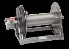
To handle single 3/8" through 5/8" I.D. hose.
• Lightweight, compact reels designed for long lengths of hose in manual and power rewind.
• Manual rewind reels include: cam-lock drag brake, spring actuated pin lock and direct crank rewind.
• Power rewind reels include: chain and sprocket drive powered by electric, hydraulic or air motor.
• Standard inlet: 90° ball bearing swivel joint, 1/2" female NPT threads.
• Standard outlet: 1/2" female NPT threads.
• Standard pressures to 3000 psi (207 bar), available up to 10,000 psi (690 bar) – must specify.
• Standard fluid temperatures from -32° F to +400 °F (0° C to +204° C). Optional temperature ratings available - consult factory.
• Rollers and roller mounting brackets are accessory items. Specify roller position.
• Heavy-Duty Upgrade Options: 3/16” thick discs, 8” diameter steel 14 gage drum, and optional pressures of 5000 or 10,000 psi, must specify when ordering.
PARTS DRAWING – ISO 90 (POWER); ISO 179 (MANUAL)
Standard configuration shown with Crank Rewind
Optional External Mounting Brackets

Part No. 9906.0027. Add 2-1/2" to the X dimensions shown in the chart.
Notes:
1. Specifications subject to change.
2 Upon request, reels can be supplied with drum lengths other than shown.
3. Weights shown in chart are for crank rewind models. ADD these amounts for power rewind models (does not apply to FedEx or UPS):
Net lbs /kg Ship lbs /kg
18/8.2 18/8.2
15/6.8 15/6.8 Air 15/6.8 15/6.8
4 Dimension “F” is the overall length of standard model reels.
5. When ordering power rewind models, prefix model number with:
A = Air Rewind –Supplied with control valve and 18" air hose.
E = Electric Rewind –12v and 24v DC rewind reels are supplied with switch and solenoid; 115v AC rewind reels are not supplied with switch but can be ordered separately.
HD = Hydraulic Rewind –Not supplied with control valve.
6. Manual rewind available in RT or LB configurations only.
7. Finish: Refer to page 3.
8. Be sure to check dimensions and weights prior to ordering.
9. Some roller options may prohibit the use of our molded chain guard.
NOTICE: A flexible connector must be used between the inlet pipe and the inlet swivel joint.
* Dimensional weight applies when shipped as a parcel package (via FedEx or UPS Ground).
*** X, Y indicate mounting holes. See page 5.
Power rewind shown
X
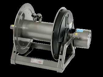
C G H Y D E 18 Phone: 518-797-3791 Toll Free: 1-877-467-3357 FAX: 518-797-3259 Email: reels@hannay.com hannay.com B C 6 152 X A F Y 10 254 D 14.12 359 G 18.12 460 H 9.88 251 E Series 1500 • Lawn Care • Pest Control • Pressure Washing • Agriculture • Steam Cleaning MANUAL OR POWER REWIND REELS
A F
Standard configuration shown with Electric Rewind (E) option
Model Number For power rewind see Note 5 Hose Capacity of Reel feet m Approx. Weight Crank Rewind lb. kg see Note 3 Reel Dimensions*** in. mm I.D. in. 3/81/25/8 NET UPS/ FedEx SHIP Wt. Freight SHIP Wt. ABE CRANK E POWER F CRANK F POWER X mm101316 O.D. in. 3/47/8 1 mm192225 1514-17-18 125 75 50 27 65* 62 11 6 17.5 19 19.25 17 9.5 38 23 15 12 30 28 279 152 445 483 489 432 241 1520-17-18 275 175 125 29 80* 64 17 12 17.5 19 25.25 23 15.5 84 53 38 13 36 29 432 305 445 483 641 584 394 1526-17-18 400 300 200 31 98* 66 23 18 17.5 19 31.25 29 21.5 122 91 61 14 45 30 584 457 445 483 794 737 546 1530-17-18 500 375 275 33 110* 68 27 22 17.5 19 35.25 33 25.5 152 114 84 15 50 31 686 559 445 483 895 838 648 1536-17-18 – 475 350 35 129* 70 33 28 17.5 19 41.25 39 31.5 – 145 107 16 59 32 838 711 445 483 1048 991 800
Electric
Hydraulic
Page 17
To handle single 5/8" or 3/4" I.D. hose.
• Lightweight, compact reels designed for long lengths of hose in manual and power rewind.
• Manual rewind reels include: cam-lock drag brake, spring actuated pin lock and direct crank rewind.
• Power rewind reels include: chain and sprocket drive powered by electric, hydraulic or air motor.
• Standard inlet: 90° ball bearing swivel joint, 1" female NPT threads.
• Standard outlet: 3/4" female NPT threads.
• Standard pressures to 2000 psi (138 bar), available up to 4000 psi (276 bar) – must specify.
• Standard fluid temperatures from -15° F to +250 °F (-26° C to +121° C). Optional temperature ratings available - consult factory.
• Rollers and roller mounting brackets are accessory items. Specify roller position.

PARTS DRAWING – ISO 136 (POWER); ISO 180 (MANUAL)
Optional External Mounting Brackets
Part No. 9906.0027. Add 2-1/2" to the X dimensions shown in the chart.
Notes:
1. Specifications subject to change.
2 Upon request, reels can be supplied with drum lengths other than shown.
3. Weights shown in chart are for crank rewind models. ADD these amounts for power rewind models (does not apply to FedEx or UPS):
Net lbs /kg Ship lbs /kg
18/8.2 18/8.2
Hydraulic 15/6.8 15/6.8
Air 15/6.8 15/6.8
4 Dimension “F” is the overall length of standard model reels.
5. When ordering power rewind models, prefix model number with:
A = Air Rewind –Supplied with control valve and 18" air hose.
E = Electric Rewind –12v and 24v DC rewind reels are supplied with switch and solenoid; 115v AC rewind reels are not supplied with switch but can be ordered separately.
HD = Hydraulic Rewind –Not supplied with control valve.
6. Manual rewind available in RT or LB configurations only.
7. Finish: Refer to page 3.
8. Be sure to check dimensions and weights prior to ordering.
9. Some roller options may prohibit the use of our molded chain guard.
NOTICE: A flexible connector must be used between the inlet pipe and the inlet swivel joint.
* Dimensional weight applies when shipped as a parcel package (via FedEx or UPS Ground).
*** X, Y indicate mounting holes. See page 5.
Power rewind shown
Y D 19 Phone: 518-797-3791 Toll Free: 1-877-467-3357 FAX: 518-797-3259 Email: reels@hannay.com hannay.com Series 1800 • Air Compressors • Washdown MANUAL OR POWER REWIND REELS
Standard configuration shown with Electric Rewind (E) option B X A F E C 6 152 Y 10 254 D 14.12 359 G 18.12 460 H 9.88 251
Model Number For power rewind see Note 5 Hose Capacity of Reel feet m Approx. Weight Crank Rewind lb. kg see Note 3 Reel Dimensions*** in. mm I.D. in. 5/83/4 NET UPS/ FedEx SHIP Wt. Freight SHIP Wt. ABE CRANK E POWER F CRANK F POWER X mm1619 O.D. in. 1 1-9/32 mm2540 1816-17-18 75 50 28 80* 63 13 8 17.5 19 23.5 19.75 11.5 23 15 13 36 29 330 203 445 483 597 502 292 1822-17-18 150 100 30 98* 65 19 14 17.5 19 29.5 25.75 17.5 46 30 14 45 29 483 356 445 483 749 654 445 1826-17-18 200 125 32 98* 67 23 18 17.5 19 33.5 29.75 21.5 61 38 15 45 30 584 457 445 483 851 756 546 1830-17-18 250150 33 110* 68 27 22 17.5 19 37.5 33.75 25.5 76 46 15 50 31 686 559 445 483 953 857 648 1836-17-18 300 200 36 129* 71 33 28 17.5 19 43.5 39.75 31.5 91 61 16 59 32 838 711 445 483 11051010 800
Electric
Page 18
Standard configuration shown with Crank Rewind
2000
Dual Hose
• Hydraulics • Spray Painting • Air/Water
To handle dual 1/4" through 1/2" I.D. hose.
• Two swivel joint inlets and two outlet risers to handle two equal lengths of hose.
• Chain-driven crank rewind or chain and sprocket rewind powered by an electric or compressed air motor.
• MX crank rewind reels have pinion brake as standard.
• Power rewind reels are not supplied with a brake.
• Standard inlets: 90° ball bearing swivel joints, 1/2" female NPT threads.
• Standard outlets: 1/2" female NPT threads.
• Standard pressures to 3000 psi (207 bar), available up to 10,000 psi (690 bar) – must specify.
• Standard fluid temperatures from -15° F to +250 °F (-26° C to +121° C). Optional temperature ratings available - consult factory.
• Reels for use with oxygen/acetylene.
See Series 2400 Hannay Reels Welding Catalog H0408-W.
X A F
PARTS DRAWING – ISO 112
Standard configuration shown with Electric Rewind (E) option
Optional External Mounting Brackets
Part No. 9906.0027.
Add 2-1/2" to the X dimensions shown in the chart.
Notes:
1. Specifications subject to change.
2 Upon request, reels can be supplied with drum lengths other than shown.
3. Weights shown in chart are for crank rewind models. ADD these amounts for power rewind models (does not apply to FedEx or UPS):
Net lbs /kg Ship lbs /kg
18/8.2 18/8.2
15/6.8 15/6.8
4 Dimension “F” is the overall length of standard model reels. MX chain-drive crank models require 2" clearance to remove crank handle.
5. When ordering power rewind models, prefix model number with:
A = Air Rewind –Supplied with control valve and 18" air hose.
E = Electric Rewind –12v and 24v DC rewind reels are supplied with switch and solenoid; 115v AC rewind reels are not supplied with switch but can be ordered separately.
MX = Chain-Driven Crank.
6. Finish: Refer to page 3.
7. Be sure to check dimensions and weights prior to ordering.
8. Some roller options may prohibit the use of our molded chain guard.
NOTICE: A flexible connector must be used between the inlet pipe and the inlet swivel joint.
* Dimensional weight applies when shipped as a parcel package (via FedEx or UPS Ground).
*** X, Y indicate mounting holes. See page 5.
Power rewind shown
C G H
E 20 Phone: 518-797-3791 Toll Free: 1-877-467-3357 FAX: 518-797-3259 Email: reels@hannay.com hannay.com
Y D
Series
MANUAL OR POWER REWIND REELS
B X A F E C 6 152 Y 10 254 D 14.12 359 G 18.12 460 H 9.88 251
Model Number For power rewind see Note 5 Hose Capacity of Reel feet m Approx. Weight Crank Rewind3 lb. kg see Note 3 Reel Dimensions*** in. mm I.D. in. 1/43/81/2 NET UPS/ FedEx SHIP Wt. Freight SHIP Wt. ABE CRANK E POWER F CRANK F POWER X mm 6 1013 O.D. in. 5/83/47/8 mm161922 2016-17-18 2/100 2/752/50 32 80* 67 13 8 19.0619 21 20.88 11.5 2/31 2/23 2/15 15 36 30330 203 484 483 533 530 292 2020-17-18 2/175 2/125 2/75 34 98* 69 17 12 19.0619 25 24.88 15.5 2/53 2/38 2/23 15 45 31 432 305 484 483 635 632 394 2026-17-18 2/275 2/200 2/125 36 110* 71 23 18 19.0619 31 30.88 21.5 2/84 2/61 2/38 16 50 32 584 457 484 483 787784 546 2030-17-18 2/350 2/250 2/175 37 129* 72 27 22 19.061935 34.88 25.5 2/107 2/76 2/53 17 59 33 686 559 484 483 889 886 648 2036-17-18 2/425 2/300 2/225 39 129* 74 33 28 19.0619 41 40.88 31.5 2/130 2/91 2/69 18 59 34838 711 484 483 1041 1038 800
Electric
Air
Page 19
To handle dual 1/4" through 1/2" I.D. hose.
• Two swivel joint inlets and two outlet risers to handle two equal lengths of hose.
• Gear-driven crank rewind.
• Pinion brake as standard.
• Standard inlets: 90° ball bearing swivel joints, 1/2" female NPT threads.
• Standard outlets: 1/2" female NPT threads.
• Standard pressures to 3000 psi (207 bar), available up to 10,000 psi (690 bar) – must specify.
• Standard fluid temperatures from -15° F to +250 °F (-26° C to +121° C). Optional temperature ratings available - consult factory.
• For power rewind, see Series 2000, page 20.
• Reels for use with oxygen/acetylene. See Series 2400 Hannay Reels Welding Catalog H0408-W.
Dual Hose
Notes:
1. Specifications subject to change.
2. Upon request, reels can be supplied with drum lengths other than shown.
3. Finish: Refer to page 3.
4. Be sure to check dimensions and weights prior to ordering.
NOTICE: A flexible connector must be used between the inlet pipe and the inlet swivel joint.
* Dimensional weight applies when shipped as a parcel package (via FedEx or UPS Ground).
*** X, Y indicate mounting holes. See page 5.
Part No. 9906.0027. Add 2-1/2" to the X dimensions shown in the chart.
Y D 21 Phone: 518-797-3791 Toll Free: 1-877-467-3357 FAX: 518-797-3259 Email: reels@hannay.com hannay.com
External
Optional
Mounting Brackets
Series G2000 • Hydraulics • Spray Painting • Air/Water MANUAL REWIND REELS
B X A F Y 10 254 D 14.12 359 G 18.12 460 H 9.88 251 E 18 457 C 8 203 PARTS DRAWING – ISO 205 Model Number Hose Capacity of Reel feet m Approx. Weight Crank Rewind lb. kg Reel Dimensions*** in. mm I.D. in. 1/43/81/2 NET UPS/ FedEx SHIP Wt. Freight SHIP Wt. A B F X mm 6 1013 O.D. in. 5/83/47/8 mm161922 G2016-17-18-8 2/752/50 2/35 40 80* 75 13 8 18.88 11.5 2/23 2/15 2/11 15 36 34 330 203 480 292 G2020-17-18-8 2/1252/100 2/50 42 98* 77 17 12 22.88 15.5 2/382/31 2/15 18 45 35 432 305 581 394 G2026-17-18-8 2/200 2/1502/100 44 110* 79 23 18 28.88 21.5 2/61 2/46 2/31 19 50 36 584 457 734 546
Standard gear-driven crank rewind with optional finish shown
Page 20
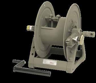
Series 3000
• Fuel Dispensing (Consult Factory) • Spray Operations
• Fire Protection
To handle 3/4" or 1" I.D. hose.
• Economical manual rewind reels for long lengths of hose.
• Choose disc rewind or removable direct crank rewind.
• Supplied with spring actuated pin lock.
• Standard inlet: 90° ball bearing swivel joint, 1" female NPT threads.
• Standard outlet: 1" female NPT thread.
• Standard: inlet, outlet riser, and hub assembly are steel. Options: swivel joint also available in aluminum or stainless steel. Riser and hub assembly also available in stainless steel.
• Standard pressures to 2000 psi (138 bar), available up to 4000 psi (276 bar) – must specify.
• Standard fluid temperatures from -15° F to +250 °F (-26° C to +121° C). Optional temperature ratings available - consult factory.
• Rollers and roller mounting brackets are accessory items. Specify roller position.
Standard configuration shown with crank handle
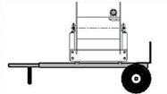
Optional Aluminum Hand Cart 4300-AL mounting available.
PARTS DRAWING – ISO 113
Notes:
1. Specifications subject to change.
2. Upon request, reels can be supplied with drum lengths other than shown and with disc sizes in other diameters.
3. Power rewind NOT available on these models.
4. Dimension “F” is the overall length of standard model reels. For crank rewind models, 3-1/2" clearance is required to remove crank.
5. Subtract 5" from “F” dimension for disc rewind models.
6. Finish: Call factory for offshore/marine finish, available at extra cost. Refer to page 3.
7. Be sure to check dimensions and weights prior to ordering.
NOTICE: A flexible connector must be used between the inlet pipe and the inlet swivel joint. *** X, Y indicate mounting holes. See page 5.
C G H
E 22 Phone: 518-797-3791 Toll Free: 1-877-467-3357 FAX: 518-797-3259 Email: reels@hannay.com hannay.com
X A F
Y D
MANUAL REWIND REELS B X A F C 10.5 267 E 24.75 629 G 27.88 708 H 15.5 394 Y 21.75 552 D 25.5 648
Model Number Hose Capacity of Reel feet m Approx. Weight Crank Rewind lb. kg Reel Dimensions*** in. mm NETSHIP A B F X I.D. in. 3/4 1 mm 19 25 O.D. in. 1-9/321-1/2 mm 33 38 3016-25-26 100 75 85 120 13 7.5 24.5 7.75 30 23 39 54 330 191 622 197 3020-25-26 150 100 94 129 17 11.5 28.5 9 46 30 43 59 432 292 724 229 3024-25-26 200 125 103 138 21 15.5 32.5 13 61 38 47 63 533 394 826 330 3028-25-26 275 175 113 155 25.5 20 37 17.5 84 53 51 70 648 508 940 445 Page 21
To handle 1-1/4" or 1-1/2" I.D. hose.
• Economical manual rewind reels for long lengths of hose.
• Choose disc rewind or removable direct crank rewind.
• Supplied with spring actuated pin lock.
• Standard inlet: 90° ball bearing swivel joint, 1-1/2" female NPT threads, and 2" Victaulic® groove.
• Standard outlet: 1-1/2" female NPT threads.
• Standard: inlet, outlet riser, and hub assembly are steel. Options: also available in aluminum or stainless steel.
• Standard pressures to 600 psi (41 bar), available up to 1000 psi (69 bar) – must specify.
• Standard fluid temperatures from -20° F to +212 °F (-29° C to +100° C). Optional temperature ratings available - consult factory.
• Rollers and roller mounting brackets are accessory items. Specify roller position.
Notes:
1. Specifications subject to change.
2. Upon request, reels can be supplied with drum lengths other than shown and with disc sizes in other diameters.
3. Power rewind NOT available on these models.
4. Dimension “F” is the overall length of standard model reels. For crank rewind models, 3-1/2" clearance is required to remove crank.
5. Subtract 5" from “F” dimension for disc rewind models.
6. Finish: Call factory for offshore/marine finish, available at extra cost. Refer to page 3.
7. Be sure to check dimensions and weights prior to ordering.
NOTICE: A flexible connector must be used between the inlet pipe and the inlet swivel joint.
*** X, Y indicate mounting holes. See page 5.
Standard configuration shown
Optional Aluminum Hand Cart 4300-AL mounting available.
Y D 23 Phone: 518-797-3791 Toll Free: 1-877-467-3357 FAX: 518-797-3259 Email: reels@hannay.com hannay.com • Fuel Dispensing (Consult Factory) • Bulk Transfer • Fire Protection Series 3500 MANUAL REWIND REELS
B X A F G H E C 10.5 267 Y D PARTS DRAWING – ISO 111 Model Number Hose Capacity of Reel feet m Approx. Weight Crank Rewind lb. kg Reel Dimensions*** in. mm NETSHIP ABDEFGHXY I.D. in. 1-1/41-1/2 mm 32 38 O.D. in. 1-13/162-1/16 mm 46 52 3520-25-26 75 50 104 139 17 11.5 25.5 24.75 30.75 27.88 15.5 9 21.75 23 15 47 63 432 292 648 629 781 708 394 229 552 3524-25-26 100 75 113 157 21 15.525.5 24.7534.75 27.88 15.5 13 21.75 30 23 51 71 533 394 648 629 883 708 394 330 552 3528-25-26 150 100 123 173 25.5 20 25.5 24.75 39.25 27.88 15.5 17.5 21.75 46 30 56 78 648 508 648 629 997 708 394 445 552 3524-30-31 150 100 124 174 21 15.525.5 28.7534.75 29.88 15.5 13 21.75 46 30 56 79 533 394 648 730 883 759 394 330 552 3528-30-31 200 150 134 184 25.5 20 25.5 28.75 39.2529.88 15.5 17.5 21.75 61 46 61 83 648 508 648 730 997 759 394 445 552 3534-30-31 – 200 147 197 31.5 26 25.5 28.75 45.25 29.88 15.5 23.5 21.75 – 61 67 89 800 660 648 730 1149 759 394 597 552 3530-33-34 – 250 138 188 27.5 22 31.5 31.75 41.25 32.38 16.5 19.5 27.75 – 76 63 85 699 559 800806 1048 822 419 495 705
Page 22
4000
• Fuel Dispensing (Consult Factory) • Water Supply
• Fire Protection • Chemical Transfer
To handle single 3/4" or 1" I.D. hose.
• Lightweight, compact reels designed for long lengths of hose in manual and power rewind.
• Manual rewind reels include: cam-lock drag brake, spring actuated pin lock and removable direct crank rewind.
• Power rewind reels include: chain and sprocket drive powered by electric, hydraulic or air. Strap brake is standard.
• Standard inlet: 90° ball bearing swivel joint, 1" female NPT threads.
• Standard outlet: 1" female NPT threads.
• Standard pressures to 2000 psi (138 bar), available up to 4000 psi (276 bar) – must specify.
• Standard fluid temperatures from -15° F to +250 °F (-26° C to +121° C). Optional temperature ratings available - consult factory.
• Rollers and roller mounting brackets are accessory items. Specify roller position.
Optional External Mounting Brackets Part No. 9906.0027. Add 2-1/2" to the X dimensions shown in the chart.
Notes:
1. Specifications subject to change.
2 Upon request, reels can be supplied with drum lengths other than shown.
3. Weights shown in chart are for crank rewind models. ADD these amounts for power rewind models (does not apply to FedEx or UPS):
Net lbs /kg Ship lbs /kg
Electric 18/8.2 18/8.2
Hydraulic 15/6.8 15/6.8
Air 15/6.8 15/6.8
4 Dimension “F” is the overall length of standard model reels. Crank rewind reels require 3-1/2" clearance to remove or install crank handle.
5. When ordering power rewind models, prefix model number with:
A = Air Rewind –Supplied with control valve and 18" air hose.
E = Electric Rewind –12v and 24v DC rewind reels are supplied with switch and solenoid; 115v AC rewind reels are not supplied with switch but can be ordered separately.
HD = Hydraulic Rewind –Not supplied with control valve.
6. Finish: Refer to page 3.
7. Be sure to check dimensions and weights prior to ordering.
8. Some roller options may prohibit the use of our molded chain guard.
NOTICE: A flexible connector must be used between the inlet pipe and the inlet swivel joint.
* Dimensional weight applies when shipped as a parcel package (via FedEx or UPS Ground).
*** X, Y indicate mounting holes. See page 5. (Also applies for external mounting brackets.)
Power rewind shown
C G
E 24 Phone: 518-797-3791 Toll Free: 1-877-467-3357 FAX: 518-797-3259 Email: reels@hannay.com hannay.com
X A F
H Y D
Series
MANUAL OR POWER REWIND REELS
B X A F E C 8 203 Y 10 254 D 14.12 359 G 18.12 460 H 9.88 251 PARTS DRAWING – ISO 68 (POWER); ISO 125 (MANUAL) Model Number For power rewind see Note 5 Hose Capacity of Reel feet m Approx. Weight Crank Rewind lb. kg see Note 3 Reel Dimensions*** in. mm I.D. in. 3/4 1 NET UPS/ FedEx SHIP Wt. Freight SHIP Wt. ABE CRANK E POWER F CRANK F POWER X mm1925 O.D. in. 1-9/321-1/2 mm3338 4018-17-18 50 35 36 80* 71 15 10 17.5 19 26.5 20.75 13.5 15 11 16 36 32 381 254 445 483 673 527 343 4024-17-18 100 50 46 98* 81 21 16 17.5 19 32.5 26.75 19.5 30 15 21 45 37 533 406 445 483 826 679 495 4030-17-18 150 75 57 110* 92 27 22 17.5 19 38.5 32.75 25.5 46 2326 50 42 686 559 445 483 978 832 648 4038-17-18 200 100 70 – 124 35 30 17.5 19 46.5 40.75 33.5 61 30 32 – 56 889 762 445 483 1181 1035 851
Page 23
Standard configuration shown with Electric Rewind (E) option
To handle single 3/4" or 1" I.D. hose.
• Lightweight, compact reels designed for long lengths of hose in manual and power rewind.
• Manual rewind reels include: gear-driven crank rewind with removable handle and adjustable brake.
• Power rewind reels include: chain and sprocket drive powered by electric, hydraulic or air motor.
• Standard inlet: 90° ball bearing swivel joint, 1" female NPT threads.
• Standard outlet: 1" female NPT threads.
• Standard pressures to 2000 psi (138 bar), available up to 4000 psi (276 bar) – must specify.
• Standard fluid temperatures from -15° F to +250 °F (-26° C to +121° C). Optional temperature ratings availableconsult factory.
• Rollers and roller mounting brackets are accessory items. Specify roller position.
Notes:
1. Specifications subject to change.
2 Upon request, reels can be supplied with drum lengths other than shown.
3. Weights shown in chart are for crank rewind models. ADD these amounts for power rewind models:
/kg
Electric 18/8.2 18/8.2
Hydraulic 15/6.8 15/6.8
Air 15/6.8 15/6.8
4 Dimension “F” is the overall length of standard model reels.
5. When ordering standard gear rewind models, prefix model number with:
G = Gear Rewind.
When ordering power rewind models, prefix model number with:
A = Air Rewind –Supplied with control valve and 18" air hose.
E = Electric Rewind –12v and 24v DC rewind reels are supplied with switch and solenoid; 115v AC rewind reels are not supplied with switch but can be ordered separately.
HD = Hydraulic Rewind –Not supplied with control valve.
6. Finish: Refer to page 3.
7. Be sure to check dimensions and weights prior to ordering.
NOTICE: A flexible connector must be used between the inlet pipe and the inlet swivel joint. *** X, Y indicate mounting holes. See page 5.
Power rewind shown
Y D 25 Phone: 518-797-3791 Toll Free: 1-877-467-3357 FAX: 518-797-3259 Email: reels@hannay.com hannay.com • Fuel Dispensing (Consult Factory) • Water Supply • Fire Protection • Chemical Transfer Series 4100 MANUAL OR POWER REWIND REELS
B X A F E C 8 203 G 18.12 460 H 9.88 251 Y 12.25 311 D 15.5 394 PARTS DRAWING – ISO 216 Model Number For power rewind see Note 5 HoseCapacityofReel feet m Approx. Weight Crank Rewind lb. kg see Note 3 Reel Dimensions*** in. mm I.D. in. 3/4 1 NETSHIP ABE CRANK E POWER FX mm 19 25 O.D. in. 1-9/321-1/2 mm 33 38 4118-17-18 50 35 62 97 15 10 18 20.5 21.5 7.5 15 11 28 44 381 254 457 521 546 190 4124-17-18 100 50 72 107 21 16 18 20.5 27.5 13.5 30 15 33 49 533 406 457 521 699 343 4130-17-18 150 75 83 118 27 22 18 20.5 33.5 19.5 46 23 38 54 686 559 457 521 851 495 4138-17-18 200 100 96 131 35 30 18 20.5 41.5 27.5 61 30 44 59 889 762 457 521 1054 698
Net lbs /kg Ship lbs
Page 24
Standard configuration shown with Electric Rewind (E) option and gear-driven crank rewind and optional finish shown
Series 6000
• Fuel Dispensing (Consult Factory) • Fire Protection • Spray Operations
Water Blasting*
Sewer Cleaning*
To handle single 1/2" through 1" I.D. hose.
• Heavy-duty reel for longer lengths of hose.
• Choose gear-driven crank rewind or chain and sprocket drive powered by an electric, hydraulic or compressed air motor.
• Crank rewind reels supplied with pinion brake; power rewind reels with a strap brake.
• Standard inlet: 90° ball bearing swivel joint, 1" female NPT threads.
• Standard outlet: 1" female NPT threads.
• Standard: inlet, outlet riser, and hub assembly are steel. Options: swivel joint also available in aluminum or stainless steel. Riser and hub assembly also available in stainless steel.
• Standard pressures to 2000 psi (138 bar), available up to 5000 psi (345 bar) – must specify.
• Standard fluid temperatures from -15° F to +250 °F (-26° C to +121° C). Optional temperature ratings available - consult factory.
X A F
• Rollers and roller mounting brackets are accessory items. Specify roller position.
• Consult factory for optional chain guard.
* Heavy-duty construction required for water blasting and sewer cleaning applications. Consult factory.
Optional Auxiliary Rewind Ring and pinion shaft rewind unit with removable crank handle.
C G
E 26 Phone: 518-797-3791 Toll Free: 1-877-467-3357 FAX: 518-797-3259 Email: reels@hannay.com hannay.com
H Y D
•
•
MANUAL OR POWER REWIND REELS
Standard configuration shown with Electric Rewind (EP) option
Optional Assembly C2 roller top wind and auxiliary rewind shown
Page 25
PARTS DRAWING – ISO 84
Notes:
1. Specifications subject to change.
2 Upon request, reels can be supplied with drum lengths other than shown and with disc sizes in other diameters.
3. Dimensions shown for reels up to and including 30-31 disc size reflect pressed frames. All others are rollformed channel frames.
4. Weights shown in chart are for crank rewind models. ADD these amounts for power rewind models.
Net lbs /kg Ship lbs /kg
Electric 40/18.1 40/18.1
Hydraulic 20/9.1 20/9.1
Air 20/9.1 20/9.1
5 When ordering power rewind models, prefix model number with: A = Air Rewind –Supplied with control valve and 18" air hose.
EP = Electric Rewind (1/2 HP) –12v and 24v DC rewind reels are supplied with switch and solenoid; 115v AC rewind reels are not supplied with switch but can be ordered separately.
HD = Hydraulic Rewind –Not supplied with control valve.
6. Finish: Refer to page 3.
7. Be sure to check dimensions and weights prior to ordering.
NOTICE: A flexible connector must be used between the inlet pipe and the inlet swivel joint.
*** X, Y indicate mounting holes.
See page 5.
† Some applications require a clutch/ reduction unit.
Power rewind shown
Y D 27 Phone: 518-797-3791 Toll Free: 1-877-467-3357 FAX: 518-797-3259 Email: reels@hannay.com hannay.com • Fuel Dispensing (Consult Factory) • Fire Protection • Spray Operations • Water Blasting* • Sewer Cleaning* Series 6000 MANUAL OR POWER REWIND REELS B X A F Y D G H E C 10.5 267
Model Number For power rewind see Note 5 Hose Capacity of Reel feet m Approx. Weight Crank Rewind lb. kg see Note 4 Reel Dimensions*** in. mm I.D. in. 1/23/4 1 NETSHIP ABDEF CRANK F POWER GHXY mm131925 O.D. in. 7/81-9/321-1/2 mm223338 6024-19-21 200 100 60 85 127 21 15.5 20.5 18.75 25.38 28.521.5 12.12 13 16.75 61 30 18 39 58 533 394 521 476 645 724 546 308330 425 6032-19-21 325 175 85 102 144 29.5 24 20.5 18.75 33.88 37 21.5 12.12 21.5 16.75 99 53 26 46 65 749 610 521 476 861 940 546 308 546 425 6024-23-24 400 150 125 92 134 21 15.5 20.5 22.75 25.38 28.5 23.5 12.12 13 16.75 122 4638 42 61 533 394 521 578 645 724 597 308330 425 6030-23-24 – 225 200 105 147 27.5 22 20.5 22.75 31.88 35 23.5 12.12 19.5 16.75 – 68 61 48 67 699 559 521 578 810 889 597 308 495 425 6038-23-24 – 300 250 120 162 35 29.5 20.5 22.75 39.38 42.5 23.5 12.12 27 16.75 – 91 76 54 73 889 749 521 578 1000 1080 597 308 686 425 6016-25-26 250 100 75 88 130 13 7.5 25.5 24.75 17.38 20.5 27.88 15.5 7.75 21.75 76 30 23 40 59 330 191 648 629 441 521 708 394 197 552 6022-25-26 450 175 125 100 142 19 13.5 25.5 24.75 23.38 26.5 27.88 15.5 11 21.75 137 84 38 4564 483 343 648 629 594 673 708 394 279 552 6028-25-26 – 275 175 113 155 25.5 20 25.5 24.75 29.88 33 27.88 15.5 17.5 21.75 – 84 53 51 70 648 508 648 629 759 838 708 394 445 552 6018-30-31 400 200 150 101 151 15 9.5 25.5 28.75 19.38 22.5 29.88 15.5 7 21.75 122 61 4646 68 381 241 648 730 492 572 759 394 178 552 6024-30-31 – 350250 113 163 21 15.525.5 28.75 25.38 28.5 29.88 15.5 13 21.75 – 107 76 51 74 533 394 648 730 645 724 759 394 330 552 6028-30-31 300 121 171 25.5 20 25.5 28.75 29.88 33 29.88 15.5 17.5 21.75 91 55 78 648 508 648 730 759 838 759 394 445 552 † 6028-33-34 400 129 179 25 20 31.5 31.7529.75 33.06 33.63 17.7517.527.75 122 59 81 635 508 800806 756 840 854 451 445 705 Page 26
Series 7000
• Hydraulics • Dual Agents
Dual Hose
To handle dual 3/4" or 1" I.D. hose.
• Two swivel joint inlets and two outlet risers to handle two equal lengths of hose.
• Choose gear-driven crank rewind or chain and sprocket drive powered by an electric, hydraulic or compressed air motor. An auxiliary rewind is standard.
• Crank rewind and power rewind reels, pinion brake is standard.
• Standard inlets: 90° ball bearing swivel joints, 1" female NPT threads.
• Standard outlets: 1" female NPT threads.
• Standard: inlet, outlet riser, and hub assembly are steel. Options: swivel joint also available in aluminum or stainless steel. Riser and hub assembly also available in stainless steel.
• Standard pressures to 2000 psi (138 bar), available up to 5000 psi (345 bar) – must specify.
• Standard fluid temperatures from -15° F to +250 °F (-26° C to +121° C). Optional temperature ratings available - consult factory.
X A F
• Consult factory for optional chain guard.
ISO 72
Standard configuration shown with Electric Rewind (EP) option
Notes:
1. Specifications subject to change.
2 Upon request, reels can be supplied with drum lengths other than shown and with disc sizes in other diameters.
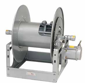
3. Dimensions shown for reels up to and including 30-31 disc size reflect pressed frames. All others are rollformed channel frames.
4. Weights shown in chart are for crank rewind models. ADD these amounts for power rewind models.
lbs /kg Ship lbs /kg
40/18.1 40/18.1
20/9.1 20/9.1
5 When ordering, prefix model number with:
A = Air Rewind –Supplied with control valve and 18" air hose.
EP = Electric Rewind (1/2 HP) –12v and 24v DC rewind reels are supplied with switch and solenoid; 115v AC rewind reels are not supplied with switch but can be ordered separately.
HD = Hydraulic Rewind –Not supplied with control valve.
MX = Chain-Driven Crank.
6. Finish: Refer to page 3.
7. Be sure to check dimensions and weights prior to ordering.
NOTICE: A flexible connector must be used between the inlet pipe and the inlet swivel joint.
*** X, Y indicate mounting holes. See page 5.
† Some applications require a clutch/reduction unit.
Power rewind shown
C G H
E 28 Phone: 518-797-3791 Toll Free: 1-877-467-3357 FAX: 518-797-3259 Email: reels@hannay.com hannay.com
Y D
MANUAL OR POWER REWIND REELS
B X A F Y D G H E C 10.5 267 6.5 165 PARTS DRAWING –
Model Number For power rewind see Note 5 Hose Capacity of Reel feet m Approx. Weight Crank Rewind lb. kg see Note 4 Reel Dimensions*** in. mm I.D. in. 3/4 1 NET Freight SHIP Wt. ABDEF CRANK F POWER GHXY mm 19 25 O.D. in. 1-9/321-1/2 mm 33 38 7024-19-21 2/60 2/25 100 142 21 15.5 20.5 21.88 29.75 32.12 21.5 12.12 13 16.75 2/18 2/8 45 64 533 394 521 556 756 816 546 308330 425 7026-23-24 2/90 2/50 105 147 23 17.5 20.5 23 31.75 34.12 23.5 12.1215 16.75 2/27 2/15 48 67 584 445 521 584 806 867 597 308 381 425 7032-25-26 2/175 2/100 129 179 29.5 24 25.5 24.75 38.25 40.62 27.88 15.5 21.5 21.75 2/53 2/31 59 81 749 610 648 629 972 1032 708 394 546 552 †7032-30-31 2/300 2/175 137 187 29.5 24 25.5 28.75 38.25 40.62 29.88 15.5 21.5 21.75 2/91 2/53 62 85 749 610 648 730 972 1032 759 394 546 552 †7024-33-34 2/225 2/150 120 170 20.5 15.5 31.5 31.7529.75 32.12 33.62 17.75 13 27.75 2/69 2/46 54 77 521 394 800806 756 816 854 451 330 705 †7032-33-34 2/350 2/225 137 187 29 24 31.5 31.75 38.25 40.62 33.62 17.75 21.5 27.75 2/107 2/69 62 85 737 610 800806 972 1032 854 451 546 705
Electric
Hydraulic
Air
Net
20/9.1 20/9.1
Page 27
To handle single 1-1/4" or 1-1/2" I.D. hose.
• Choose gear-driven crank rewind or chain and sprocket drive powered by an electric, hydraulic or compressed air motor.
• Crank rewind reels supplied with pinion brake and power rewind reels with a strap brake.
• Standard inlet: 90° ball bearing swivel joint, 1-1/2" female NPT threads, and 2" Victaulic® groove.
• Standard outlet: 1-1/2" female NPT threads.
• Standard: inlet, outlet riser, and hub assembly are steel. Options: also available in aluminum or stainless steel.
• Standard pressures to 1000 psi (41 bar), consult factory for other pressure ratings – must specify.

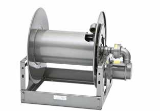
• Standard fluid temperatures from -20° F to +212 °F (-29° C to +100° C). Optional temperature ratings available - consult factory.
• Rollers and roller mounting brackets are accessory items. Specify roller position.
• Consult factory for optional chain guard.
Optional Auxiliary Rewind
Ring and pinion shaft rewind unit with removable crank handle.
Notes:
1. Specifications subject to change.
2 Upon request, reels can be supplied with drum lengths other than shown and with disc sizes in other diameters.
3. Dimensions shown for reels up to and including 30-31 disc size reflect pressed frames. All others are rollformed channel frames.
4. Weights shown in chart are for crank rewind models. ADD these amounts for power rewind models.
5 When ordering, prefix model number with:
A = Air Rewind –Supplied with control valve and 18" air hose.
EP = Electric Rewind (1/2 HP) –12v and 24v DC rewind reels are supplied with switch and solenoid; 115v AC rewind reels are not supplied with switch but can be ordered separately.
HD = Hydraulic Rewind –Not supplied with control valve.
6. Finish: Refer to page 3.
7. Be sure to check dimensions and weights prior to ordering.
NOTICE: A flexible connector must be used between the inlet pipe and the inlet swivel joint.
*** X, Y indicate mounting holes. See page 5. †Some applications require a clutch/reduction unit.
Power rewind shown
Y D 29 Phone: 518-797-3791 Toll Free: 1-877-467-3357 FAX: 518-797-3259 Email: reels@hannay.com hannay.com • Fuel Dispensing (Consult Factory) • Bulk Transfer • Suction/Discharge (Consult Factory) Series 7500 MANUAL OR POWER REWIND REELS B X A F Y D G H E C 10.5 267
Model Number For power rewind see Note 5 Hose Capacity of Reel feet m Approx. Weight Crank Rewind lb. kg see Note 4 Reel Dimensions*** in. mm I.D. in. 1-1/41-1/2 NETSHIP ABDEF CRANK F POWER GHXY mm 32 38 O.D. in. 1-13/162-1/16 mm 46 52 7528-19-21 70 50 104 146 25.5 20 20.5 18.75 32 33 21.5 12.12 17.5 16.75 21 15 47 66 648 508 521 476 813 838546 308 445 425 7538-23-24 175 100 130 172 35 29.5 20.5 22.75 41.542.5 23.5 12.12 27 16.75 53 30 59 78 889 749 521 578 10541080 597 308 686 425 7520-25-26 75 50 106 148 17 11.5 25.5 24.75 23.5 24.5 27.88 15.5 9 21.75 23 15 48 67 432 292 648 629 597 622 708 394 229 552 7528-25-26 125 100 123 165 25.5 20 25.5 24.75 32 33 27.88 15.5 17.5 21.75 38 30 56 75 648 508 648 629 813 838 708 394 445 552 7522-30-31 125 100 118 168 19 13.5 25.5 28.75 25.5 26.5 29.88 15.5 11 21.75 38 30 54 76 483 343 648 730 648 673 759 394 279 552 †7528-30-31 200 150 131 181 25.5 20 25.5 28.75 32 33 29.88 15.5 17.5 21.75 61 46 59 82 648 508 648 730 813 838 759 394 445 552 †7526-33-34 200 175 133 183 22.5 17.5 31.5 31.75 29.25 30.25 33.62 17.75 15 27.75 61 53 60 83 572 445 800806 743 768 854 451 381 705
PARTS DRAWING – ISO 18
Net lbs
Ship lbs /kg Electric 40
40/18.1 Hydraulic 20
20/9.1 Air 20/9.1 20/9.1
/kg
/18.1
/9.1
Standard configuration shown with Electric Rewind (EP) option
Page 28
Series 8000
To handle single 1-1/2" or 2" I.D. hose.
• Heavy-duty reel designed for longer lengths and larger diameters of hose through 2" I.D.
• Choose gear-driven crank rewind or chain and sprocket drive powered by an electric, hydraulic or compressed air motor.
• Crank rewind reels supplied with a pinion brake; power rewind reels with a strap brake.
• Standard inlet: 90° ball bearing swivel joint, 2" female NPT threads.
• Standard outlet: 2" female NPT threads.
• Standard: inlet, outlet riser, and hub assembly are steel. Options: also available in aluminum or stainless steel.
• Pressures to 600 psi (41 bar). Standard fluid temperatures from -20° F to +212 °F (-29° C to +100° C). Consult factory for other pressures and temperatures.
• Rollers and roller mounting brackets are accessory items. Specify roller position.
• Consult factory for optional chain guard.
PARTS DRAWING – ISO 35
Standard configuration shown with Electric Rewind (EP) option
Chain Clutch-Reduction Units
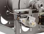
For use on power reels with disc diameter 39" or larger and/or when increased torque and slower rewind speeds are required. Factory installed when specified or available as an accessory item.
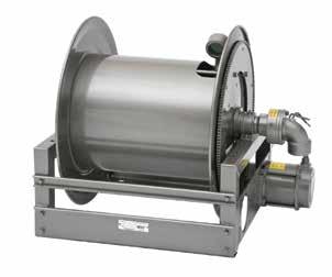
Notes:
1. Specifications subject to change.
2 Upon request, reels can be supplied with drum lengths other than shown and with disc sizes in other diameters.
3. Weights shown in chart are for crank rewind models. ADD these amounts for power rewind models.
4 When ordering power rewind models, prefix model number with:
A = Air Rewind –Supplied with control valve and 25" air hose.
EP = Electric Rewind (1/2 HP) –12v and 24v DC rewind reels are supplied with switch and solenoid; 115v AC rewind reels are not supplied with switch but can be ordered separately.
HD = Hydraulic Rewind –Not supplied with control valve.
5. Finish: Refer to page 3.
6. Be sure to check dimensions and weights prior to ordering.
NOTICE: A flexible connector must be used between the inlet pipe and the inlet swivel joint. *** X, Y indicate mounting holes. See page 5.
Power rewind shown
C G H
E 30 Phone: 518-797-3791 Toll Free: 1-877-467-3357 FAX: 518-797-3259 Email: reels@hannay.com hannay.com • Bulk Transfer • Fueling Applications (Consult Factory) • Chemical Transfer • General Dispensing • Suction/Discharge (Consult Factory)
X A F
Y D
MANUAL OR POWER REWIND REELS
B X A F Y D G H E C 15.5 393
Model Number For power rewind see Note 4 Hose Capacity of Reel feet m Approx. Weight Crank Rewind lb. kg see Note 3 Reel Dimensions*** in. mm I.D. in. 1-1/2 2 NETSHIP ABDEF CRANK F POWER GHXY mm 38 51 O.D. in. 2-1/162-9/16 mm 52 65 8234-26-27-15.5 80 60 120 170 26.25 20 27 25.7533.7534.75 26.62 13.7518.75 23.25 24 18 54 77 667 508 686 654 857 883 676 349 476 591 8238-26-27-15.5 100 75 145 195 30.25 24 27 25.75 37.75 38.75 26.62 13.7522.75 23.25 30 23 66 88 768 610 686 654 959 984 676 349 578 591 8246-26-27-15.5 145 100 196 245 38.25 32 27 25.7545.7546.75 26.62 13.75 30.75 23.25 44 30 89 112 972 813 686 654 1162 1188 676 349 781 591 8226-33-34-15.5 85 60 80 150 17.75 11.5 31.5 31.75 25.25 26.25 33.38 17.75 10.25 27.75 26 18 36 68 451 292 800806 641 667 848 445 260 705 8234-33-34-15.5 150 115 133 230 26.25 20 31.5 31.7533.7534.75 33.38 17.75 18.75 27.75 46 35 60 105 667 508 800806 857 883848 445 476 705 8238-39-40-15.5 340 225 218 420 30.25 24 40 39 37.75 38.75 39.88 20.38 22.75 37 104 69 99 191 768 6101016 991 959 984 1013 518 578 940
Net lbs /kg Ship lbs /kg Electric 40/18.1 40/18.1 Hydraulic 20/9.1 20/9.1 Air 20/9.1 20/9.1
Page 29
To handle 2-1/2" or 3" I.D. hose.
• Heavy-duty reel designed for longer lengths and larger diameters of hose through 3" I.D.
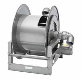
• Choose gear-driven crank rewind or chain and sprocket drive powered by an electric, hydraulic or compressed air motor.
• Crank rewind reels supplied with a pinion brake; power rewind reels with a strap brake.
• Standard inlet: 90° ball bearing swivel joint, 3" female NPT threads.
• Standard outlet: 3" female NPT threads.
• Standard: outlet riser, and hub assembly are aluminum with ductile inlet.
Options: swivel joint also available in aluminum or stainless steel. Riser and hub assembly also available in stainless steel.
• Pressures to 300 psi (21 bar). Standard fluid temperatures from -20° F to +212 °F (-29° C to +100° C). Consult factory for other pressures and temperatures.
• Rollers and roller mounting brackets are accessory items. Specify roller position.
• Consult factory for optional chain guard.
PARTS DRAWING – ISO 57
Standard configuration shown with Electric Rewind (EP) option
Chain Clutch-Reduction Units
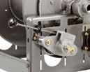
For use on power reels with disc diameter 39" or larger and/or when increased torque and slower rewind speeds are required. Factory installed when specified or available as an accessory item.
Notes:
1. Specifications subject to change.
2 Upon request, reels can be supplied with drum lengths other than shown and with disc sizes in other diameters.
3. Weights shown in chart are for crank rewind models. ADD these amounts for power rewind models.
4 When ordering power rewind models, prefix model number with:
A = Air Rewind –Supplied with control valve and 25" air hose.
EP = Electric Rewind (1/2 HP) –12v and 24v DC rewind reels are supplied with switch and solenoid; 115v AC rewind reels are not supplied with switch but can be ordered separately.
HD = Hydraulic Rewind –Not supplied with control valve.
5. Finish: Refer to page 3.
6. Be sure to check dimensions and weights prior to ordering.
NOTICE: A flexible connector must be used between the inlet pipe and the inlet swivel joint.
*** X, Y indicate mounting holes. See page 5.
Power rewind shown
Y D 31 Phone: 518-797-3791 Toll Free: 1-877-467-3357 FAX: 518-797-3259 Email: reels@hannay.com hannay.com • Fueling Applications (Consult Factory)• Bulk Transfer • Suction/Discharge (Consult Factory) • High Volume Application • Chemical Transfer Series 9000 MANUAL OR POWER REWIND REELS
B X A F Y D G H E C 20 508
Model Number For power rewind see Note 4 Hose Capacity of Reel feet m Approx. Weight Crank Rewind lb. kg see Note 3 Reel Dimensions*** in. mm I.D. in. 2-1/2 3 NETSHIP ABDEF CRANK F POWER GHXY mm 64 76 O.D. in. 3-3/163-3/4 mm 81 95 9332-33-34-20 30 25 147 217 23.75 17.5 31.5 31.7533.75 33.2533.88 18 16.25 27.75 9 8 67 98 603 445 80080 857 845 861 457 413 705 9338-33-34-20 45 35 187 257 30.25 24 31.5 31.75 40.25 39.75 33.88 18 22.75 27.75 14 11 85 117 768 610 800 807 10221010 861 457 578 705 9346-33-34-20 60 50 237372 38.25 32 31.5 31.75 48.25 47.75 33.88 18 30.75 27.75 18 15 108169 972 813 800 807 1226 1213 861 457 781 705 9338-39-40-20 90 80 239 480 30.25 24 40 39 40.25 39.75 40.3820.88 22.75 37 27 24 108 218 768 6101016 991 102210101026 530 578 940 9334-45-46-20 130 115 361 525 26.25 20 46 45 36.25 35.75 46.38 23.88 18.75 43 40 35 164 239 667 508 1168 1143 921 908 1178 607 476 1092
Electric
40
Hydraulic 20/9.1 20/9.1 Air 20/9.1 20/9.1
Net lbs /kg Ship lbs /kg
40/18.1
/18.1
Page 30
To handle 3/8" through 1" I.D. hose.
• Continuous flow reels with swivel joint inlet, fluid hub, outlet riser.
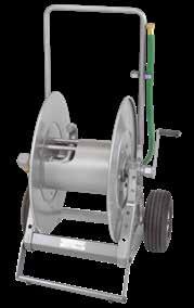
• Direct crank rewind and cam-lock drag brake.
• One -piece foot and removable steel handlebar.
• GH prefix to model number (e.g., GH1100, GHAT1200) includes garden hose thread on outlet, 5' lead-in hose, hose end clips.
Model 1100
• Standard inlet: 90° ball bearing swivel joint, 1/2" female NPT threads.
• Standard outlet: 1/2" female NPT threads.
• Pressures to 3000 psi (207 bar).
• Standard fluid temperatures from -32° F to +400 °F (0° C to +204° C). Optional temperature ratings available - consult factory.
• Rubber tires standard.
Model AT1200
• Standard inlet: 90° balance pressure swivel joint, 1" female NPT threads.
• Standard outlet: 1" female NPT threads.
• Standard pressures to 2000 psi (138 bar), available up to 4000 psi (276 bar) – must specify.
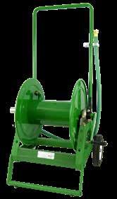
• Standard fluid temperatures from -40° F to +250 °F (-40° C to +121° C). Optional temperature ratings available - consult factory.
• Pneumatic tires standard.
PARTS DRAWING – 1100–ISO 48; AT1200–ISO 87
C G H Y D E 32 Phone: 518-797-3791 Toll Free: 1-877-467-3357 FAX: 518-797-3259 Email: reels@hannay.com hannay.com • Grounds Maintenance • Restaurants/Hotels • Washdown Operations • Home Use Series
PORTABLE HOSE REELS ON WHEELS
X A F
1100/AT1200
B C A F D G H E
Model Number Hose Capacity of Reel feet m Approx. Weight lb. kg Reel Dimensions in. mm I.D. in. 3/81/25/83/4 1 NETSHIP ABCDEFGH mm1013161925 O.D. in. 3/47/8 1 1-9/321-1/2 mm1922253338 1100 275 175 125 47 100* 21.25 12 6 20.12 16.5 25.25 42.5 14.38 84 53 38 ––21 46 540 305 152 511 419641 1080 365 AT1200 – 350250150 100 86 147* 25.88 11.5 8 22.62 22.75 27 42.5 18.12 – 107 76 46 30 39 67 657 292 203 575 578 686 1080 460 Notes: 1. Specifications subject to change. 2. Some assembly required. 3. Finish: Refer to page 3. 4. Be sure to check dimensions and weights prior to ordering. *Dimensional weight applies when shipped as a parcel package (via FedEx or UPS Ground). GH1100 Standard configuration shown in optional green powder coat finish GHAT1200 Standard configuration shown GH1100 shown Page 31
For storage of hose, cable, rope or wire.
• Direct crank rewind and cam-lock drag brake.
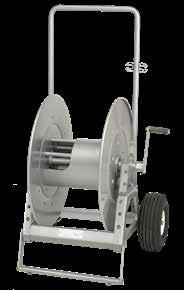
• One -piece foot and removable steel handlebar.
Model C1150
• A 1-1/8" x 2-3/8" (28 mm x 60 mm) opening in the drum to initiate winding.
• Rubber tires standard.
Model ATC1250
• A larger version of the C1150 with a 4-1/2" x 9" (114 mm x 229 mm) drum opening.
• Pneumatic tires standard.
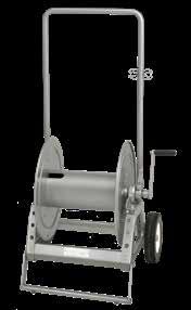
Y D 33 Phone: 518-797-3791 Toll Free: 1-877-467-3357 FAX: 518-797-3259 Email: reels@hannay.com hannay.com Optional Folding Handle For compact storage • Industrial Maintenance • Construction • Agriculture • Grounds Maintenance Series C1150/ATC1250 PORTABLE STORAGE REELS ON WHEELS
B C A F D G H E
O.D.,
Notes: 1. Specifications subject to change. 2. Some assembly required. 3. When ordering specify model number,
length, and weight of cable, hose, etc. 4. Finish: Refer to page 3.
5. Be sure to check dimensions and weights prior to ordering.
ATC1250 Shown ATC1250 Standard configuration shown C1150 Standard configuration shown
DRAWING – C1150–ISO 48; ATC1250–ISO 87 Model Number Cable Capacity of Reel feet m Approx. Weight lb. kg Reel Dimensions in. mm Gauge/Number of Conductors NETSHIP ABCDEFGH 16/314/312/310/3 O.D. in. .390.530.600.690 mm10141518 C1150 1100 500 400 300 44 100* 21.25 12 6 20.12 16.5 24.62 42.5 14.38 335 152 122 91 20 46 540 305 152 511 419 625 1080 365 ATC1250 1800 950 750 550 84 147* 25.88 11.5 8 22.62 22.75 27 42.5 18.12 549 290 229 168 38 67 657 292 203 575 578 686 1080 460 Page 32
*Dimensional weight applies when shipped as a parcel package (via FedEx or UPS Ground).
PARTS
Series C1500
To handle single 1/4" through 1" O.D.
• Reels are designed for storage of long lengths of hose, cable, rope, wire or other materials.
• A 1-1/8" x 2-3/8" (28 mm x 60 mm) opening in the drum to initiate winding.
• Manual rewind reels include: cam-lock drag brake, spring actuated pin lock and direct crank rewind.
• Power rewind reels include: chain and sprocket drive powered by electric, hydraulic or air motor..
• Optional divider discs can be placed at almost any point. Be sure to specify spacing of discs on your order.
• Rollers and roller mounting brackets are accessory items. Specify roller position.
Notes:
External Mounting Brackets Part No. 9906.0027. Add 2-1/2" to the X dimensions shown in the chart.
Optional
Standard configuration with optional finish shown
1. Specifications subject to change.
2 Upon request, reels can be supplied with drum lengths other than shown and with disc sizes in other diameters.
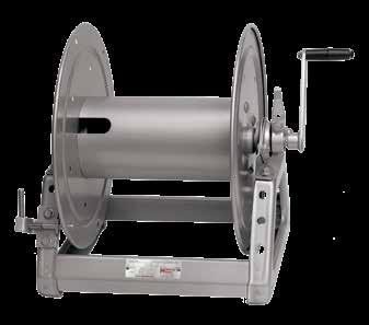
3. Dimensions reflect pressed frames.
4. Weights shown in chart are for crank rewind models. ADD these amounts for power rewind models (does not apply to FedEx or UPS): Net lbs /kg Ship lbs /kg
5 When ordering power rewind models, prefix model number with:
A = Air Rewind –Supplied with control valve and 18" air hose.
E = Electric Rewind –12v and 24v DC rewind reels are supplied with switch and solenoid; 115v AC rewind reels are not supplied with switch but can be ordered separately.
HD = Hydraulic Rewind –Not supplied with control valve.
6. Finish: Refer to page 3.
7. Be sure to check dimensions and weights prior to ordering.
*Dimensional weight applies when shipped as a parcel package (via FedEx or UPS Ground).
*** X, Y indicate mounting holes. See page 5.
Crank rewind shown
C G H Y D E 34 Phone: 518-797-3791 Toll Free: 1-877-467-3357 FAX: 518-797-3259 Email: reels@hannay.com hannay.com
X A F
• Hose • Rope • Cable • Wire
STORAGE REELS: MANUAL OR POWER REWIND
B X A F E C 6 152 Y 10 254 D 14.12 359 G 18.12 460 H 9.88 251 PARTS DRAWING – ISO 218 Model Number For power rewind see Note 5 Hose Capacity of Reel feet m Approx. Weight Crank Rewind lb. kg see Note 4 Reel Dimensions*** in. mm O.D. in. mm 1/4 6 1/2 13 3/4 19 1 25 NET UPS/ FedEx SHIP Wt. Freight SHIP Wt. ABE CRANK E POWER F CRANK F POWER X C1514-17-18 1300 325 150 75 23 65* 58 11 6 17.5 19 18 15.5 9.5 396 99 46 23 10 30 26 279 152 445 483 457 394 241 C1520-17-18 – 650 300 150 25 80* 60 17 12 17.5 19 24 21.5 15.5 – 198 91 46 11 36 27 432 305 445 483 610 546 394 C1526-17-18 – 900 450 225 27 98* 62 23 18 17.5 19 30 27.5 21.5 – 274 137 69 12 45 28 584 457 445 483 762 699 546 C1530-17-18 – 1000 550 275 29 110* 64 27 22 17.5 19 34 31.5 25.5 – 305 168 84 13 50 29 686 559 445 483 864 800 648
Electric
18
Hydraulic
15/6.8 Air
15/6.8
18/8.2
/8.2
15/6.8
15/6.8
Page 33
To handle single 1/2" through 1-1/2" O.D.
• A 4-1/2" x 9" (114mm x 229mm) opening in the drum to initiate winding.
• Designed for storage of long lengths of hose, cable, rope, wire or other materials.
• Choose disc rewind or removable direct crank rewind.
• Supplied with spring actuated pin lock.
• Optional divider discs can be placed at almost any point. Be sure to specify spacing of discs on your order.
• Rollers and roller mounting brackets are accessory items. Specify roller position.
• For power rewind, see Series C in cable reels catalog H0507-C.
Optional Aluminum Hand Cart 4300-AL mounting available.
Notes:
1. Specifications subject to change.
2 Upon request, reels can be supplied with drum lengths other than shown and with disc sizes in other diameters.
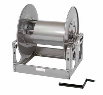
3. Dimensions reflect pressed frames.
4. Series C3200 requires 3-1/2" clearance to remove crank handle.
5. Subtract 5" from “F” dimension for disc rewind on C3200 Series.
6. Finish: Refer to page 3.
7. Be sure to check dimensions and weights prior to ordering.
*** X, Y indicate mounting holes. See page 5.
Standard configuration with crank handle shown
Y D 35 Phone: 518-797-3791 Toll Free: 1-877-467-3357 FAX: 518-797-3259 Email: reels@hannay.com hannay.com B X A F Y 21.75 552 D 25.5 648 G H E C 10.5 267 • Hose • Rope • Cable • Wire Series C3200 STORAGE REELS: MANUAL REWIND
PARTS DRAWING – ISO
Model Number Hose Capacity of Reel feet m Approx. Weight Crank Rewind lb. kg Reel Dimensions*** in. mm O.D. in. mm 1/2 13 3/4 19 1 25 1-1/4 32 1-1/2 38 NETSHIP ABE CRANK F CRANK GHX C3218-25-26-10.5 1000 450 225 125 90 85 127 15 9.5 24.7522.75 27.88 15.5 7 305 137 69 38 27 39 58 381 241 629 578 708 394 178 C3228-25-26-10.5 – 1000 500 325 200 109 151 25.5 20 24.75 33.25 27.88 15.5 17.5 – 305 152 99 61 49 68648 508 629 845 708 394 445 C3234-25-26-10.5 – 1300 650 400 275 122 164 31.5 26 24.75 39.25 27.88 15.5 23.5 – 396 198 122 84 55 74 800 660 629 997 708 394 597 Page 34
117
Series CHC
Series CHC reels are used in chemical distribution/delivery for a variety of applications including: commercial/community pools, water parks, toxic waste recycling, bulk handling of acid, bleach, chlorine, pesticides, fertilizers and more.
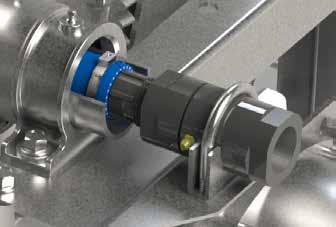
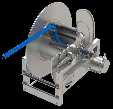
To handle single 3/8" through 1-1/2" I.D.
• Handles 3/8" through 1-1/2" ID hose, ranging from 50 ft up to 200 ft in length. For larger ID hose please consult factory.
• Standard inlet: CPVC swivel joint resists corrosion and provides longer life.
• Standard fluid temperatures from -15° F to +250 °F (-26° C to +121° C). Optional temperature ratings available - consult factory.
• Slotted hub for hose passage, with drum cut out on opposite side from the swivel joint. Fluid will not come in contact with metal, as the hose acts as the sole fluid path.
X A F
• Manual or power rewind with optional auxiliary crank rewind on specific models.
• Special swivel mounting bracket with clamp to hold the CPVC swivel in place.
ORDERING INFORMATION:
Contact Hannay Reels Inside Sales Department for more information. Be sure to provide detailed specifications on hose type, ID/OD, fluid and application information when ordering.
C G
E 36 Phone: 518-797-3791 Toll Free: 1-877-467-3357 FAX: 518-797-3259 Email: reels@hannay.com hannay.com • Chlorine • Pesticides • Fertilizers • Acid
H Y D
CHEMICAL REELS: MANUAL OR POWER REWIND
Detailed cut-out of slotted hub to show hose passage
Page 35
Close-up of CPVC swivel, clamp and mounting bracket.
To handle single 3/8" through 5/8" I.D. hose.
• Lightweight, low-profile reels designed for hose lengths up to 500 ft.
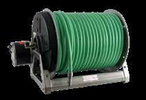
• Primarily 304 SST construction, including discs, axle hub, and welded frame.
• Non-SST components: Drum (Aluminum), Swivel Joint and Bearings (Plated).
• Manual (direct crank) reels include both pin lock and 3-position cam-lock drag brake.

• Electric rewind reels (denoted by letter ‘E’ at end of model) feature plated chain/sprocket drive with guard.
• Standard inlet: 90° full-flow swivel, 1/2" FNPT threads. Standard outlet: 1/2" FNPT threads.
• Standard pressure rated to 3000 psi (207) bar. Standard fluid temperatures from -32° F to +400 °F (0° C to +204° C).
• Consult factory for other pressures and temperatures.
Options:
• 304 SST stackable frame (for manual rewind reels).
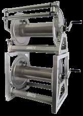
• SST rollers and roller mounting brackets.
• Drum, swivel joint and bearings all upgradeable to SST.
• Power rewind reels: Motor available in 12 or 24VDC, as well as 115VAC.
Notes:
1. Specifications subject to change.
2. Other models available than those shown.
3. Dimension “F” is the overall length of standard model reels.
4. Electric rewind reels indicated with ‘E’ in model suffix (example - SNC-12E).
5. Be sure to check dimensions and weights prior to ordering.
NOTICE: A flexible connector must be used between the inlet pipe and the inlet swivel joint.
* Dimensional weight applies when shipped as a parcel package (via FedEx or UPS Ground).
*** X, Y indicate mounting holes.
Electric rewind shown
Y D 37 Phone: 518-797-3791 Toll Free: 1-877-467-3357 FAX: 518-797-3259 Email: reels@hannay.com hannay.com • Lawn Care • Pest Control • Fertilizer Mixes Series SNC CHEMICAL REELS: MANUAL OR POWER REWIND
Model SNC-18 ► manual rewind reel with optional rollers
◄ Model SNC-18E Electric Rewind (E) (hose not included)
B C 6 152 X A F Y 10 254 D 14 356 G 18.12 460 H 9.88 251 E Model Number Hose Capacity of Reel feet m Approx. Weight lb. kg Reel Dimensions*** in. mm I.D. in. 3/81/25/8 NET UPS/ FedEx SHIP Wt. Freight SHIP Wt. A B E F X mm101316 O.D. in. .65.81 1 mm172125 SNC-12 300 200 125 29 80* 64 17 12 17.5 25.62 15.5 84 53 38 13 36 29 432 305 445 651 394 SNC-18 400 300 200 31 98* 66 23 18 17.5 31.62 21.5 122 91 61 14 45 30 584 457 445 803 546 SNC-22 500 400 275 33 110* 68 27 22 17.5 35.62 25.5 152 114 84 15 50 31 686 559 445 905 648 SNC-12E 300 200 125 47 80* 82 17 12 19 23 15.5 84 53 38 21 36 37 432 305 483 584 394 SNC-18E 400 300 200 49 98* 84 23 18 19 29 21.5 122 91 61 22 45 38 584 457 483 737 546 SNC-22E 500 400 275 51 110* 86 27 22 19 33 25.5 152 114 84 23 50 39 686 559 483 838 648
Model SNC-18 ► two manual rewind reels shown with optional stacking frame and rollers
Page 36
Series VAC4000
To handle single 1-1/2" I.D. industrial vacuum hose
• NOTE: Standard inlet/outlet are slip fit connections, not threaded connections.
• Includes permanently attached crank handle and cam-lock drag brake.
• Rollformed channel frame for heavy duty applications.
• Internal hub connection to fit hose cuff.
NOTE: These reels are NOT for solid or liquid suction. Please refer to our Pumper Cleaner catalog for vacuum reel options with solid or liquid applications
Notes:
1. Specifications subject to change.
2 Upon request, reels can be supplied with drum lengths other than shown.
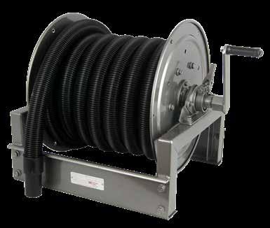
3. Dimension “F” is the overall length of standard model reels.
4. Be sure to check dimensions and weights prior to ordering.
* Dimensional weight applies when shipped as a parcel package (via FedEx or UPS Ground).
*** X, Y indicate mounting holes. (Also applies for external mounting brackets.)
X
F C G H Y D E 38 Phone: 518-797-3791 Toll Free: 1-877-467-3357 FAX: 518-797-3259 Email: reels@hannay.com hannay.com • Shop Vacuum Applications • Car Detailing • Dust/Debris Collection Only
A
VACUUM REELS: MANUAL REWIND
Model Number Hose Capacity of Reel feet m Approx. Weight lb. kg Reel Dimensions*** in. mm I.D. in. 1-1/2 NET UPS/ FedEx SHIP Wt. Freight SHIP Wt. ABCDEFGHXY mm38 O.D. in. 1.84 mm47 VAC4020-17-18-8 25 38 82 73 17 12 8 18 16.50 24.88 18.13 9.889.50 14.25 8 17 37 33 431 305 203 457 419 632 460 251 241 362 VAC4024-17-18-8 35 42 94 77 21 16 8 18 16.50 28.8818.13 9.88 13.50 14.25 11 19 43 35 533 406 203 457 419 734 460 251 343 362 VAC4028-17-18-8 50 46 98 81 25 20 8 18 16.50 32.88 18.13 9.88 17.50 14.25 15 21 45 37 635 508 203 457 419 835 460 251 445 362 A E B C F D G H X Y
Standard configuration shown (hose not included).
Page 37
VAC4000
VACN900 Standard Features:
• To handle 1-1/2" ID industrial vacuum hose. NOTE: Standard inlet/outlet are slip fit connections, not threaded connections
• N-series has a narrow frame and compact mounting base, allows for different mounting options: floor, ceiling or wall.
• Non -sparking ratchet assembly locks hose at different payout lengths and 4-way roller assembly to guide hose.
VAC900/VAC2900 Standard Features:
• VAC900: to handle 1-1/2" ID vacuum hose; VAC2900: to handle 2" ID vacuum hose. NOTE: Standard inlet/outlet are slip fit connections, not threaded connections
• Roll -formed channel frame for heavy-duty applications, allows different mounting options: floor, ceiling or wall.
• Non -sparking ratchet assembly locks hose at different payout lengths and 4-way roller assembly to guide hose.
NOTE: These reels are NOT for solid or liquid suction. Please refer to our Pumper Cleaner catalog for vacuum reel options with solid or liquid applications.
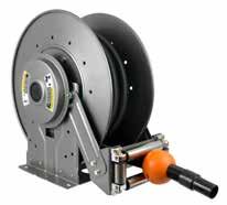
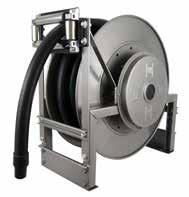
Notes: A hose stop is necessary to keep spring from unwinding.
1. Specifications subject to change.
2. Reel models and capacities shown are for standard drag applications; for vertical lift applications, consult factory.
3. Be sure to check dimensions and weights prior to ordering.
*** X, Y indicate mounting holes.
Y D 39 Phone: 518-797-3791 Toll Free: 1-877-467-3357 FAX: 518-797-3259 Email: reels@hannay.com hannay.com •Shop Vacuum Applications • Car Detailing • Dust/Debris Collection Only Series VACN900/VAC900 VACUUM REELS: SPRING REWIND B C X A F Y D G H E SR (STD) VR (OPT) TR (OPT) TR (Wallmount) Available Roller Positions B C X A F Y D G H E Model Number Hose Capacity of Reel feet m Approx. Weight lb. kg Standard Roller Assy. Reel Dimensions*** in. mm I.D. in. 1-1/2 2 NETSHIP ABDEFGHXY mm3851 O.D. in. 1.842.34 mm4759 VACN918-23-24-10.5L 25 – 60 95 N306 12 6 12 24 13.25 24 12.63 1010 8– 27 43 305 152 305 610 337 610 320 254254 VACN920-23-24-10.5L 35 – 62 97 N308 14 8 12 24 15.25 24 12.6312 10 11 – 28 44 356 203 305 610 387 610 320 305 254 VAC920-28-29-10.5J 50 – 76 111 R308 13.25 8 28.5 26.75 16.5 28.25 14.88 8.5 23.25 15 – 34 50 337 203 724 679 419 718 378 216 591 VAC2920-28-29-10.5J – 25 77 112 R2308 13.25 8 28.5 26.7516.75 28.25 14.88 8.5 23.25 –8 3551 337 203 724 679 425 718 378 216 591 VAC2922-28-29-10.5J – 35 79 113 R2310 15.25 1028.5 26.7518.75 28.25 14.88 10.5 23.25 – 11 3651 387 254 724 679 476 718 378 267 591 VAC2920-33-34-10.5J – 50 92 127 R2308 13.25 8 33 31.7516.75 33.63 17.75 8.5 27.75 – 15 42 58 337 203 838 806 425 854 451 216 705 VAC900
Optional TR configuration shown (hose not included)
Series ►
VACN900
VAC900/VAC2900
◄ VACN900 Series S tandard SR configuration shown (hose not included)
Page 38
Family owned and operated since 1933, Hannay Reels is the world leader in both OEM and aftermarket applications. Hannay offers thousands of standard hose reel and cable reel models, as well as unmatched custom capabilities. We can easily and affordably customize a reel to meet your exact specifications – built to last, delivered fast. Additional catalogs are available through your local Hannay Reels dealer or online at hannay.com.


MADE IN USA Phone: 518-797-3791 Toll Free: 1-877-467-3357 FAX: 518-797-3259
Welding Reels Mobile and Fixed Installations Arc Welding Gas Welding Cutting Operations Family owned and operated since 1933 Welding Reels • Mobile and fixed installations • Arc welding • Gas welding • Cutting operations Family owned and operated since 1933 Cable Reels Rescue and HazMat Operations Agriculture Grounds Maintenance and MRO Electric Tools Portable Lighting Broadcast/Entertainment Auxiliary Leads for Power Generation Hoist and Crane Operations Static Grounding Utility Grounding Video Inspection Cable Reels • Electric Tools • Crane operations • Portable LIghting • Live and storage reels • Video/Broadcast • Static and Utility grounding reels Information on ordering reels and spec’ing accessories for reels: Selecting the right reel Reel components Ordering Options How to spec Hannay Reel Reel Spec Worksheet Hannay Reels Sales Policies Y D H G E Family owned and operated since 1933 Ordering & Accessory Guide Ordering & Accessory Guide • Selecting the right reel • Reel components • Available accessories • How to spec and order reels and accessories • Ordering options • Hannay Reels policies B X A F C G H Y D E Spray and Pressure Washing Hose Reels Pressure Washing Steam Cleaning Spray Operations Auto Washing Processing Plants Tree Spraying Vehicle Maintenance Lawn Care Service Agriculture Family owned and operated since 1933 Spray and Pressure Washing Hose Reels • Washdown/Power Wash • Pest Control/Fertilizers • Air/Water/Grease • Steam Cleaning • Spray operations • Por table hose reels Stainless Steel Reels •Washdown/Power Wash •Food & Beverage Processing • Chemical Processing •Potable Water • Fueling •Steam Cleaning Stainless Steel Reels Washdown | Chemical Transfer Potable Water | Pharmaceuticals & Cosmetics Steam Cleaning Food Processing Marine | Fueling | Fire Protection | Dairy Operations Bottling Plants Family owned and operated since 1933 Find reels for every need. Learn more about all of our reels, including specs, drawings, and even how to select the right reels and accessories for your industry. View all our reel catalogs online at hannay.com Form H-0308-H REV 9 3-23 553 State Route 143 | Westerlo, New York 12193 Email: reels@hannay.com | hannay.com All Hannay reels are constructed of quality heavy gauge steel (optional aluminum or stainless steel also available on most models). Page 39
