POWER TRANSMISSION & CONVEYOR BELTING


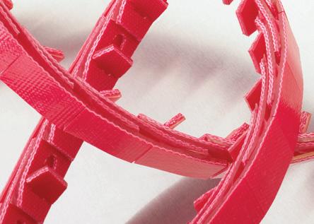
POWERTWIST DRIVE, SuperTLink and NuTLink belts are designed perform when black rubber belts fail. They perform as a permanent replacement for black rubber v-belt in power transmission applications. Our link belts provide time and cost saving benefits to maintenance engineers and equipment designers through longer belt life, faster installation, and increased drive efficiency.
You’ll find our POWERTWIST belts in the following markets:
• Climate Control
• Data Centers
• Distribution Centers
• Livestock Farming
• Glass
• Meat Processing
• Mining & Aggregate
• Packaging
• Tile
• Wood Processing
POWERTWIST MOVE link belts install in minutes without dismantling conveyor components with no welding required. These link belts are unaffected by extreme temperatures, water, oils, grease, and common chemicals. Whether your application requires reduced contact surface, high grip, abrasion resistance, non-marking, high temperature, oil, and chemical resistance, there’s a Fenner Industrial Motion link belt to meet your need.
Our POWERTWIST MOVE link belts are often found in these markets:
• Distribution Centers
• Glass
• Food Processing
• Meat Processing
• Packaging
• Tile
Eagle polyurethane belts are the backbone of our conveying portfolio. Our comprehensive range of high quality non-reinforced and reinforced belting in round and V profiles can be used in endless applications. We offer over 400 FDA compliant products and our belts are available with special top surfaces. Our custom design capabilities include special profiles, dual durometer, static dissipative, UV stabilized, tracking features, and ridged profiles.
Our Eagle polyurethane belts are found in many markets including:
• Distribution Centers
• Food Processing
• Gypsum
• Meat Processing
• Packaging
• Tile
Trackstar long-wearing UHMW Belt & Chain Guides fight friction and reduce costs by increasing the life of your belts or chains. We offer wide range of standard profiles for use in guiding belts, chain, and cables. Our two-piece guide and channel design simplify installation and replacement and many profiles are available from stock with same-day shipping.
• Distribution Centers
• Food Processing
• Glass
• Gypsum
• Meat Processing
• Packaging
• Tile


Elastomer
• Not all product in-stock, please call for availability.
• Some diameters and cross sections may be subject to minimum orders. Dimensions are for reference only.
• Flat belting available in Eagle Orange 85. Additional cross sections, colors, and durometers are available.
• Contact Applications Engineering at AE@fenner.com for design assistance.
• Provide time and cost saving benefits to maintenance engineers and equipment designers
• Longer belt life in even the harshest environments
• Easier, faster installation without tear-downs or struggling with motor bases
* ISO 1813:1998 inspected and certified by Fenner Industrial Motion.
* ISO 1813:1998 inspected and certified by Fenner Industrial Motion.
* ISO 1813:1998 inspected and certified by Fenner Industrial Motion.
• Install on captive drives and fixed center drives
• Make matching sets
• Better drive efficiency due to minimal belt elongation
• Reduced noise, longer bearing life due to low belt vibration


Round belts are commonly run in pulleys with a round groove; see Figure 1a. In the absence of round groove pulleys, they can also be used in V-groove pulleys (Figure 1b). The table at right shows the dimensional data for a round belt used in a V-groove pulley.
Note:
V belts in “classical” A, B, C, D and light duty 3L cross sections are designed to fit RMA compliant pulleys as per the groove details illustrated in Figure 2.
All flat belts have a natural tendency to move laterally. Therefore a flat or straight pulley is not recommended, as the belt would walk off the pulley. To keep the belt in the center of the pulley it must have a crown. Figure 3a illustrates a round crown and is the preferred method. A modified round crown as illustrated in Figure 3b is also acceptable. A flat pulley with guide flanges (Figure 3c) is not recommended. Even with the guide flanges the belt will move laterally and potentially could climb up onto them.
Round belts are commonly run in pulleys with a round groove; see Figure 1a. In the absence of round groove pulleys, they can also be used in V-groove pulleys (Figure 1b). The table at right shows the dimensional data for a round belt used in a V-groove pulley.
V belts in “classical” Z/10, A/13, B/17, C/22 and D/32 cross sections are designed to fit ISO and DIN 2215 compliant pulleys as per the groove details illustrated in Figure 2.
Note: above dimensions are belt fit in groove under no tension.
All flat belts have a natural tendency to move laterally. Therefore a flat or straight pulley is not recommended, as the belt would walk off the pulley. To keep the belt in the center of the pulley it must have a crown. Figure 3a illustrates a round crown and is the preferred method. A modified round crown as illustrated in Figure 3b is also acceptable. A flat pulley with guide flanges (Figure 3c) is not recommended. Even with the guide flanges the belt will move laterally and potentially could climb up onto them.
All belts require a certain amount of tension to function properly in the application. The specific installation tension is determined from several factors including belt type, construction and working load. Belt details are in the Technical Data section of this catalog and working load is derived from your application.
Non-Reinforced Belting: When non-reinforced belting is stretched and released, elasticity is the property that brings the material back to its original shape. This “memory” is what gives our non-reinforced belting its self-tensioning properties. When a non-reinforced belt is first installed (stretched) the material does not return to 100% of its original length and continues to lose elasticity over its life span. This loss in elasticity is evident as tension decay. To overcome tension decay effects, a non-reinforced belt requires a relatively high install tension. Installation tensions ranging from 6% to 10% will normally be sufficient for most applications. If higher tensions are required, the application may exceed the belt’s load capacity.
Reinforced Belting: Reinforced belts contain a reinforcing tensile member which increases the belt’s modulus of elasticity. This reduces the belt’s ability to stretch and minimizes tension decay. This allows a reinforced belt to carry a greater load than a non-reinforced belt. Since an endless reinforced belt is essentially a fixed length, it cannot be stretched on like a non-reinforced belt. Consequently, reinforced belts require a mechanical take-up mechanism to apply the appropriate installation tension as well as accommodating any eventual small amount of tension decay that may occur. This mechanism should accommodate at least 4% of the belt’s length.
In this section, we will refer to two different lengths that are defined as follows:
1. Reference Length: The length determined by taking a measuring tape and following the path of the belt around all of the pulleys, or through computer aided design (CAD) techniques. This length may also be obtained from the equation below. Take up mechanisms should be adjusted to the minimum position to allow for maximum adjustment of the belt prior to taking or calculating length. Note: this equation applies to two-pulley drives only.
where: L = reference length
C = center of pulley shaft to center of pulley shaft distance
D = pitch diameter of large pulley
d = pitch diameter of small pulley
2. Install Length: The length the belt is made to prior to welding or joining.
Apply the following formulas to determine the Install Length from Reference Length:
Butt weld non-reinforced:
Install Length = Reference Length ÷ (1 + % tension)
Example: Reference Length for a non-reinforced belt is 44" (1120mm), requires 8% tension and will be butt welded. Install Length is calculated on right.
Overlap weld reinforced: Install Length = Reference Length + 1.5" (38mm)
Example: Reference Length for a reinforced belt is 44" (1120mm) and will be overlap welded. The overlap weld consumes 1.5" (38mm) of belt length. Install Length is calculated on right.
Butt weld reinforced: Install Length = Reference Length
Example: Reference Length for a reinforced belt is 44" (1120mm) and will be butt welded. The weld consumes a negligible amount of belt length, consequently, Install Length and Reference Length are the same. Install Length is calculated on right.
Link Belting: Install length = Reference Length minus (1 - 2%)
Example: Reference Length for a link belt is 44" (1120mm).
Install Length removing 2% is calculated on right. Remove links to get as close as possible to Install Length.
The temperature range of polyurethane belting is determined by the thermoplastic resin. Like all thermoplastic resins its physical properties change with changes in temperature. At higher temperatures the material will soften, lose strength and can elongate excessively to the point of premature failure. At lower temperatures the material will become more brittle and stiff which can result in cracking. The temperature ranges are for guidance and listed under each individual belt type in the Material Properties section.
The most common serious mistake in designing belt drives is the selection of a pulley diameter that is too small. In most cases, non-reinforced belts can operate on smaller diameter pulleys than belts with a reinforcing tensile member. Reinforced belts require a larger pulley diameter to prevent premature flex fatigue failure of the tensile member. Listed under each individual belt type’s technical data is the recommended minimum pulley diameter. Smaller diameters can be used only if a reduction in belt service life is acceptable.
1. Refer to the Technical Data chart for the belt material and cross section selected.
2. Use the following formula that meets your application requirements (Note: if belt supported by rollers use .17 for µ):
a. Horizontal Transport with Slider Bed
Te = Wt × µ + Bwt
b. Horizontal Transport with Slider Bed and Product Accumulation
Te = Wt × µ + Bwt + Awt
c. Incline or Decline Transport with Slider Bed
Te = Wt × (Ht + µ × C2 + Ht2 ) + Bwt
C
d. Incline or Decline Transport with Slider Bed and Product Accumulation
Te = Wt × (Ht + µ × C2 + Ht2 ) + Bwt + Awt
C
3. Determine Tight Tension (T1).
Flat and round belts: T1 = Te × 2
V belts: T1 = Te × 1.25
Where:
Te = Effective Tension
Wt = Total Weight on Conveyor
C = Conveyor Center Distance
Bwt = Belt weight/unit length × C
Awt = Accumulating weight × µ´ (where µ´ is the COF between belt and product)
Ht = Incline or decline height
µ = COF on slider bed material from chart
4. Refer to the Technical Data chart for the material and cross section selected and compare T1 to the Working Load at maximum % tension. If only one belt is desired, T1 may not be greater than the Working Load at maximum % tension. If more than one belt is required, divide T1 by the Working Load at maximum % tension to arrive at number of belts. Round up to the nearest whole number of belts.
5. Find load per belt by dividing T1 by number of belts. From the Technical Data chart, determine the percent installed tension for the load per belt.
To determine the required belt length, please refer to the “Belt Installation Length” section on the previous page.
Type of belt being considered = Eagle Orange 85 in ¼" round
Head-to-tail center distance (C) = 10 feet
Incline or decline = none
Product accumulation on belt(s)? = no
Total weight on belt(s) = 15 lbs.
Type of belt support = UHMW slider bed
2. Horizontal Transport with Slider Bed.
Since the belt will run in UHMW slider bed the COF(µ) of .45 is used from Technical Data chart. From the chart the belt weight is .026 lbs/ft giving a total belt weight of .26 lbs (.026 × 10').
Te = 15 lbs × .45 + .26 = 7.01
3. Determine Tight Tension (T1). round belts T1 = 7.01 × 2 = 14.02
4. Refer to the Technical Data chart for the material and cross section selected and compare T1 to the Working Load at 10% tension. If only one belt is desired, T1 may not be greater than the Working Load at 10% tension. If more than one belt is required, divide T1 by the Working Load at 10% tension to arrive at number of belts. Round up to the nearest whole number of belts. ¼" round rated 4.9 lbs @ 10% tension. 14.02 ÷ 4.9 = 2.86 use 3 belts
5. Find load per belt by dividing T1 by number of belts. From the Technical Data chart, determine the percent installed tension for the load per belt. Load/belt = 14.02 ÷ 3 = 4.67 lbs
Corresponding installed tension = 9.7%
Eagle Orange 85 in 6mm round
Head-to-tail center distance (C) = 3 meters
Incline or decline = none
Product accumulation on belt(s)? = no
Total weight on belt(s) = 6 kg
Type of belt support = UHMW slider bed
2. Horizontal Transport with Slider Bed. Since the belt will run in UHMW slider bed the COF(µ) of .45 is used from Technical Data chart. From the chart the belt weight is .034 kgs/m giving a total belt weight of .102 kg (.034 × 3m).
Te = 6 kg × .45 + .102 = 2.802 kg
3. Determine Tight Tension (T1). round belts T1 = 2.802 × 2 = 5.604kg = 54.98 Newtons (5.604 × 9.81)
4. Refer to the Technical Data chart for the material and cross section selected and compare T1 to the Working Load at 10% tension. If only one belt is desired, T1 may not be greater than the Working Load at 10% tension. If more than one belt is required, divide T1 by the Working Load at 10% tension to arrive at number of belts. Round up to the nearest whole number of belts.
6mm round rated 19.4 N @ 10% tension. 54.98 ÷ 19.4 = 2.83 use 3 belts
5. Find load per belt by dividing T1 by number of belts. From the Technical Data chart, determine the percent installed tension for the load per belt. Load/belt = 54.98 N ÷ 3 = 18.33 Newtons Corresponding installed tension = 9.6%
Polyurethane is extremely resistant to many industrial oils and chemicals, but not all. Below are a wide variety of oils and chemicals found in industrial applications. Consult Fenner Industrial Motion Applications Engineering group for assistance on projects with design criteria outside these parameters, or obtain a sample belt and determine its compatibility in the precise operating conditions.
Aluminum Chloride, 10%
Ammonium Chloride, 10%
Bleaching Agent, 40% B Tricresyl Phosphate
Bleaching Agent, 100% C
Calcium Chloride, 40% C Oils
Caustic Soda, 10%
Cola
ASTM Oil #1
ASTM Oil #2
Ferric Chloride, 10% C ASTM Oil #3
Hydrogen Peroxide, 3% B Brake Fluid (ATE or ATS)
Isopropanol, 50% C Gear Box Oil (SAE 90)
Magnesium Chloride, 30% C Hydraulic Fluid
Potassium Chloride, 40% C Hydraulic/Water Emulsion
Potassium Dichromate, 10% C Mineral Oil
Potassium Permanganate, 5% C Motor Oil
Sea Water
Paraffin Oil
Sodium Bisulfate, 10% C Petroleum (Texas Sour Crude)
Sodium Chloride, 10% C Power Steering Fluid
Sodium Hypochlorite, 5% C Skydrol 500 Oil
Sodium Thiosulfate, 20% A Transmission Oil
Water, Deionized
Methylene Chloride
Pyrrolidone
Trichloroethylene
POWERTWIST MOVE SuperGrip Top PU Purple, Orange Top
POWERTWIST MOVE SuperGrip Top PVC Purple, Green Top RoHS
POWERTWIST MOVE Friction Top Purple RoHS
POWERTWIST MOVE Bridge Top™ Purple, White Inserts RoHS
POWERTWIST MOVE RCS Purple, White Tabs RoHS
POWERTWIST Roller Drive™ Red RoHS
POWERTWIST Antistatic † Blue RoHS
* Contact temperature
† ISO 1813:1998 inspected and certified by Fenner Industrial Motion.
Our Trackstar Guides are produced using only the highest quality virgin black UHMW-PE material to ensure minimum friction and maximum wear resistance.
Continuous Service Temp in air (max) (° F)
Volume Resistivity (Ohm/cm)
>10
* Industry standard testing method using slurry of 60% aluminum oxide and 40% water at a rotation speed of 1750 rpm for two hours. A lower number indicates better abrasion resistance.


• Elastic O-Rings for line shaft, live and motor driven roller conveyors
• High coefficient of friction
• Popular 1/8", 3/16", 1/4", 5mm and 6mm sizes in stock
• Contact Fenner Industrial Motion for sizes not listed
• O-Rings for Powered live and motor driven roller conveyors
• Available in Translucent Blue (3/16”) and Translucent Red (.210”)
• Designed to be installed at 20% installation tension
• O-Rings for Powered live and motor driven roller conveyors
• Available in Green (3/16”) and Black (.216”)
• Designed to sit below roller surface when installed at 24% tension
• Twisted O-Rings are an ideal fast fit solution for live roller conveyors
• Twisted loop construction packaged with metal hooks. Plastic hooks also available
• No need to dismantle drive components
Let us do the work for you and take the hassle out of fabricating your own endless belts
• Available in all Eagle Belting colors and durometers (except Can Cable)
• Rapid order turnaround
Eagle Blue Green 85 5400545
Eagle Clear 85 50910318 3/16" x 7-3/4"
Eagle Clear 85 50540015 3/16" x 8-1/2"
Eagle Clear 85 50540017 3/16"


Eagle Poly-V belts are PJ-profile belts designed specifically for roller conveyor applications. Made from polyurethane with elastic reinforcement, Eagle Poly-V belts provide the same load capacity as conventional rubber PJ belts with several additional benefits.
Product Features
• Abrasion resistant polyurethane improves belt life and performance in curves
• Self-tensioning, elastic reinforcement delivers consistent performance
• Higher coefficient of friction provides lower install tension and reduced belt fatigue
• Oil, grease and chemical resistant

10mm, 12mm, 12.7mm, 1/2" Round Cross Sections
Round Belting Round


• Manufactured to OEM specifications
• Always a consistent profile with ideal hole alignment
• Always in stock, ready to go to you!


• Long lasting, minimal stretch replacement for PVC Bands on wallboard forming lines. Significantly increased life on lines exceeding 350'/min
3
• Fit and forget installation reduces labor and downtime costs
• Insignificant band stretch — the same perfect impression day 1 and day 100
• Temperature resistance up to 180°F (82°C)
• Thermal splicing for a tough, seamless, flexible joint that maintains a perfect indentation
• Full weld in 12 minutes
• No board scrap generated from joint
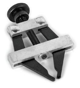
• Prevents surface scoring due to Eagle Taper Edge Band rubbing against worn return support brackets
• Easy to install mounting bracket with hand knob for quick adjustment and release
• Solid polymer plain bearing allows low-friction rotation

* Unit designed to plug into a power transformer
1/4" and 5/16" Die Set 5700400
3/8" and 1/2" Die Set 5700410
9/16", 5/8" and 16mm Die Set 5700420
3/4" and 19mm Die 5700430
5mm Die 5700600
6mm Die 5700601
Kit Includes: Welder, Control Box, Set of Dies, Flash Cutters, Cutting Shears, Carrying Case
Kit includes: Welder, Flat Plate Adapters, Professional Battery Charger, (4) D Cell NiMH Batteries, Blade Release Tape, Cutting Shears, Flash Cutters, Tool Bag
7mm Die 5700602
8mm Die 5700603
9mm Die 5700604 10mm Die 5700605 12mm Die 5700606 18mm Die 5700608
20mm Die 5700620
Z/10 Die Set 5700610
A Hyfen Die Set 5700440
A/13 Die Set 5700611
A Ridge–Top Die Set 5700470
B Hyfen Die Set 5700453
B/17 Die Set 5700612
B Ridge-Top Die Set 5700490
C Hyfen Die Set 5700457
C/22 Die Set 5700613
D Hyfen Die Set 5700460
A Die Set for Hyfen CXF and CXR 5700480
B Die Set for Hyfen CXF and CXR 5700472
C Die Set for Hyfen CXF and CXR 5700476
D Die Set for Hyfen CXF and CXR 5700474


Installation is simple with standard 120" C channels in galvanized steel, 304 stainless steel, or anodized aluminum (C3 only). Either tack weld or bolt into place with optional mounting holes.
Trackstar Channels are stocked in North America and supplied in 120" standard lengths. Subject to a minimum order quantity. Dimensions are in inches and are for reference only.
* Call for quote and lead time
The “C” channel design features a two-piece construction for quick and easy replacement of UHMW inserts. “C” channel guide rails are available in Black or White (FDA/USDA approved material.)
Trackstar Guides are stocked in North America and supplied in 120" standard lengths. Subject to a minimum order quantity. Dimensions are in inches and are for reference only.
* Call for quote and lead time
*
10mm, 12mm, 12.7mm, 1/2” GB1003-5G GB1003-5S
13mm, 14mm, 9/16” GB1004-5G GB1004-5S
15mm, 16mm, 5/8”
18mm, 19mm, 20mm, 3/4” GB1007-5G*
Trackstar Guides are stocked in North America and supplied in 120" standard lengths. Subject to a minimum order quantity.
Dimensions are in inches and are for reference only.

* Call for lead time
Dimensions are in inches and are for reference only.
50-1
GS1100-1G* GS1100-1S*
* Call for quote and lead time
* Call for quote and lead time


C
D


At Fenner Precision Polymers, A Michelin Group Company, we are proud to keep your business in motion. As a supplier of critical components and engineered solutions for conveying, motion control and power transmission applications, our trusted brands are recognized globally for providing unique solutions that solve complex problems and build sustainable growth. We strive to partner closely with you so we can always provide expert-level support and powerful results that keep our world moving forward.


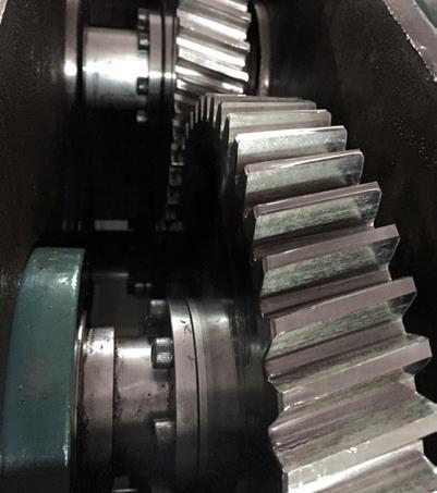

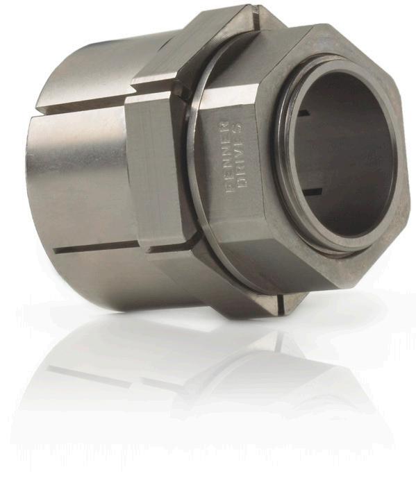
The B-LOC brand is synonymous with world class quality, engineering excellence and unrivaled customer support. Fenner Industrial Motion B-LOC Keyless Bushings provide a high capacity, zero-backlash shaft-to-hub connection by using the simple wedge principle. An axial force is applied by series of annular screws to engage circular steel rings and mating tapers. The resulting wedge action creates a radial force on the tapered rings, one of which contracts to squeeze the shaft while the other expands and presses into the component bore.
B-LOC keyless bushings appear in these markets:
• Climate Control
• Distribution Centers
• Food Processing
• Glass
• Livestock Farming
• Meat Processing
• Mining & Aggregate
• Oil & Gas
• Packaging
• Wood Processing
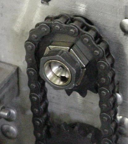
Trantorque, the original single nut keyless bushing is used from gears to cams, timing belt sprockets to conveyor rolls, and climate control fan hubs to grinding wheels. The extensive range of Trantorque keyless bushings offers easy to use options for mounting and adjusting position sensitive, zero backlash drive components and accessories.
Trantorque keyless bushings appear in the following markets:
• Climate Control
• Distribution Centers
• Fitness
• Food Processing
• Glass
• Livestock Farming
• Meat Processing
• Mining & Aggregate
• Oil & Gas
• Packaging
• Wood Processing


Once you have decided that a keyless locking device is the right solution, your next big decision is which series of Fenner Industrial Motion Trantorque or B-LOC Keyless Locking Device to choose. While the underlying engineering principle for both Trantorque and B-LOC is exactly the same, the functionality of each may appeal to different applications and situations.
B-LOC Compression Hubs
WK Couplings
At the broadest level, keyless locking devices may be split into two categories, internal locking devices (Trantorque and B-LOC Keyless Bushings) and external locking devices (B-LOC Shrink Discs, WK Couplings, and Compression Hubs). Selecting an external locking device is relatively straightforward. If you are joining two solid shafts at their ends, see the section on B-LOC WK Couplings. To connect most industry standard coupling hubs or flanges, gearboxes with hollow-shaft outputs, or other similar geometries see the B-LOC Shrink Disc section. If the component you are mounting has a narrow hub or has a short length through-bore, like a plate sprocket, see the section on B-LOC Compression Hubs.
Most applications, however, consist of a shaft and bored component that require the use of a keyless bushing. Many more factors play into the proper selection of a keyless bushing and are briefly addressed below and in the accompanying table.
Shaft size may immediately determine whether you use a Trantorque or B-LOC Keyless Bushing. A Trantorque can accommodate shaft sizes as small as 1/8" (3mm) while the smallest shaft a B-LOC will fit is 1/4" (6mm). At the other end of the spectrum, Trantorque tops out at 3" (75mm) and the largest B-LOC will accommodate shafts approaching 24" (600mm). Larger and smaller versions of all units may be available as MTOs (Made To Order).
As a practical matter, under most circumstances our Technical Services will recommend a Trantorque for shaft sizes 1-1/2" and under and a B-LOC for shaft sizes over 1-1/2". These are considered the optimal ranges for the product lines taking maximum advantage of each product’s unique installation method.
The most obvious difference when comparing a B-LOC to a Trantorque Keyless Bushing is the installation method. All B-LOC units use a plurality of screws; all Trantorque units use a single hex nut. Your particular application will be your guide as to which method is preferred. The advantages of a single hex nut, as used in a Trantorque Keyless Bushing, are speed and simplicity of installation and removal. For installation, simply tighten the single hex nut to the specified installation torque and your connection is complete. Removal is just as straightforward. Merely loosen the same hex nut and the unit will disengage. The cost for this simplicity is a relatively high installation torque requirement, which may present a challenge for larger units.
Since the force needed to draw the mating tapers of a B-LOC Keyless Bushing together is distributed among many screws, the installation torque of an individual screw is relatively low. This allows for effortless installation of even the largest units. The price paid for this low installation torque is a more timely and complex installation and removal process. The screws must be slowly and equally tightened in series until the final installation torque is achieved. Since most B-LOC units have self locking tapers, the removal process requires loosening all screws and backing off the unit.
There are several other design points that may help guide you in your selection process. OD to ID ratios vary widely from product to product. If your design requires a small OD/ID ratio, consider either a B-LOC B800 or a Trantorque OE. While all Fenner Drives Keyless Bushings are designed to transmit high torque loads, if you have an extremely demanding application, a double taper B-LOC B112, B113 or B115 may be required. If you are mounting plate sprockets or other thin components, B-LOC Compression Hubs could be the solution. Other factors to consider include axial movement, recessed installation, corrosion protection, and RoHS compliance. The table is designed to help make your selection process easier, but if you are ever in doubt, please contact Fenner Industrial Motion Technical Service at AE@fenner.com. We will be happy to guide you to the perfect keyless locking device solution.


Recommended surface finish for shafts and hub bores to be used with Fenner Industrial Motion Keyless Bushings is between 32 and 125 micro-inch (0.8 and 3.2 micro-meter) RMS. A smoother finish — such as that found on components supplied TG&P (turned, ground and polished) — is NOT recommended and can result in a failure of the connection. Note that surface finishes below 32 microinch (0.8 micro-meter) RMS can be roughened using longitudinal abrasion with a bastard file, emery paper or similar to achieve a surface finish within the recommended range.
Fenner Keyless Bushings are precision machined to maximize concentricity and minimize runout. The final installed concentricity of mounted components depends on several variables, including the components themselves and the installation technique employed. Special attention to proper installation will be required for B-LOC B400 series units. Overall, however, concentricity is typically excellent for the majority of Fenner Keyless Bushings.
Fenner Industrial Motion Keyless Locking Devices are only recommended for use with drive components constructed of polymers if a metal sleeve of sufficient size and strength is incorporated into the bore of the mounted component. For design and manufacturing support of a suitable sleeve consult with a Fenner Applications Engineer.
Similar to conventional shrink or press fits, connections using Fenner Keyless Bushings are generally not affected by temperature changes as long as the shaft, hub and bushing are made of the same material and temperatures are applied uniformly to each. For situations where one or more of the components are made of a material with a different coefficient of thermal expansion or where thermal gradients/cycles are present, fit pressures can be impacted. Please consult a Fenner Applications Engineer.
Mounting bearings with a Fenner Industrial Motion Keyless Bushing is not recommended. The expansion forces generated will distort the bearing’s inner race, causing premature failure.
Additional torque capacity can be achieved by arranging two or more B-LOC Keyless Bushings in series. In these situations, where access to locking screws is available from one side only, the total torque capacity of the connection is not a linear function of the number of units applied. For applications involving B-LOC Keyless Bushings in series, please consult with a Fenner Industrial Motion Applications Engineer.
Do not use anaerobic adhesives such as Loctite, Permatex or similar compounds with Fenner Keyless Bushings. Doing so results in unknown contact pressures and capacities. Further, disassembly may be compromised when such compounds are applied to the keyless bushing, the shaft and/or the hub bore. Proper installation assures sufficient pre-load so that threads are self-locking, even in cases where the keyless bushing is subjected to extreme vibratory conditions.
Hollow shafts with bores exceeding 35% of outside diameter usually require a reduction of contact pressures in order to avoid permanent shaft deformation. Special considerations arise when installing Fenner Industrial Motion Keyless Bushings onto hollow shafts. Please consult with a Fenner Industrial Motion Applications Engineer for a trouble free hollow shaft connection.
Trantorque and B-LOC Keyless Locking Devices are supplied with an oil specific to the product line. The listed performance data requires the use of these lubricants to provide the necessary coefficient of friction to the sliding surfaces. Some products have strategically applied grease or oil (in some cases food grade) to achieve performance.
Trantorque and B-LOC Keyless Locking Devices are made from carbon and heat treated alloy steels. B-LOC Keyless Bushings are manufactured from heat treated carbon and alloy steels. For applications in corrosive environments, corrosion resistance can be improved through sealing with grease or silicone, the use of protective cover plates, application of industry standard plating materials (e.g., nickel, thin dense chrome, etc.) or by specifying the product in stainless steel or other corrosion resistant materials. Please consult with a Fenner Industrial Motion Applications Engineer for more details.
T = peak drive torque = nominal torque multiplied by a variable safety factor to account for stall or start-up conditions, mass accelerations, impact loads, etc. Nominal drive torque can be calculated as follows:
Mtnom (ft lb) = 5252 × HP rpm
Mtnom (Nm) = 9550 × kW rpm
Consult with a Fenner Industrial Motion Applications Engineer in cases where “T” is uncertain.
Mt = The rated torque capacity of one Fenner Industrial Motion Keyless Bushing installed according to our instructions. Published torque capacities are calculated without using a safety factor and should be considered as the point where a connection could slip if a higher torque is applied. Therefore, always select a unit where Mt ≥ T.
The installation torque shown in the data tables is the maximum installation torque recommended for the product. Torque capacity and contact pressures are a linear function of installation torque (Ma) and can be adjusted if necessary by changing Ma within the following limits:
Series M a
Trantorque up to 50% lower
B-LOC B103/B106/B109 up to 20% lower
B-LOC B400 up to 20% higher or up to 20% lower
B-LOC B800 up to 20% lower
B-LOC B112/B113 up to 40% lower
B-LOC B115 up to 30% lower
B-LOC B117 up to 20% lower
Th = transmissible thrust, determined by using the following equation:
Th = 2 × Mt
d
where: d = shaft diameter
Mt = rated torque capacity
TORQUE AND THRUST COMBINED
Simultaneous transmission of torque and thrust requires calculating a resultant torque:
Mtres =
T2 + F × d 2 2 ( )
where: T = peak drive torque
F = peak thrust load
d = shaft diameter
Select a unit where Mt ≥ Mtres
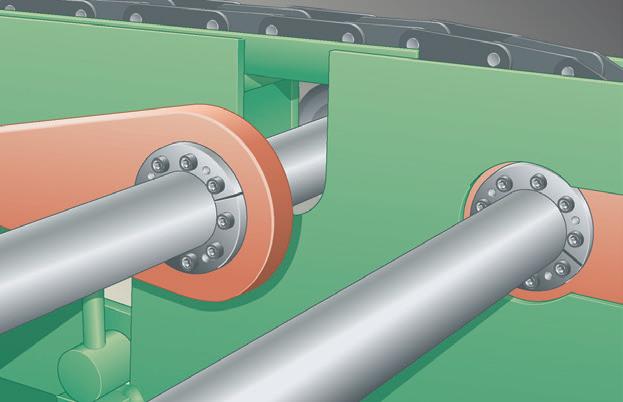
Bending moments are a crucial sizing factor in applications where a radial load from chain pull, the weight of components, etc. acts significantly outside the keyless bushing centerline. Typical applications include rolls or conveyor pulleys where shaft deflection due to radial loads results in a bending moment between shaft and end disc. Generally, bending moments change from a positive to a negative value during each rotation and are designated as rotating or reversing bending moments.
Fenner Industrial Motion Keyless Bushings are well suited to transmit rotating/reversing bending moments. Compiled using relevant data gleaned from numerous successful heavy-duty applications in conveyor pulleys as well as pertinent investigations by independent institutions, the following bending moment capacities apply:
Series Bending Moment Capacity (M b )
Trantorque 0.28 × Mt
B-LOC B103/B106/B109 0.28 × Mt
B-LOC B400 0.22 × Mt
B-LOC B800 0.28 × Mt
B-LOC B115 0.32 × Mt
B-LOC B112/B113 0.35 × Mt
B-LOC B117 0.65 × Mt
where: Mt = rated torque capacity (from specification tables)
Consult with a Fenner Industrial Motion Applications Engineer on applications where the actual bending moment exceeds these recommended limits.
TORQUE AND BENDING COMBINED
Simultaneous transmission of torque and bending requires calculating a resultant torque:
Mtb =
T2 + (2 × Mb)2
where: T = peak drive torque
Mb = bending moment
Always select a unit where Mt ≥ Mtb and Mb is within the limits appearing under Bending Moment Capacity above.
When an existing shaft diameter does not fit the bore of a standard Fenner Industrial Motion Keyless Bushing, we recommend using an adapter sleeve that can be sized to allow for the use of a standard unit and the existing shaft. The maximum wall thickness of the adapter sleeve should be approximately 10% of the existing shaft diameter.
Note that in order to maximize the torque capacity of a sleeved keyless bushing connection, the shaft/sleeve bore interface must be free of any lubricant. This makes the sleeve outside diameter/ keyless bushing bore the point of lowest torque capacity (provided the sleeve outside diameter is less than 1.25 times the shaft diameter) and allows for full use of the larger keyless bushing’s higher torque capacity.
Notes:
1. Sleeve ID = ds -0/+.001" (.025mm) where ds = shaft diameter
2. Sleeve OD = d +0/-TL for keyless bushing to be used
3. Install dry (cleaned with non-petroleum-based solvent) at shaft/sleeve bore interface for coefficient of friction μ = 0.15
4. Torque capacity at sleeve OD = Mt for keyless bushing to be used
5. Torque capacity on shaft = Mt × ds d × 1.25
6. Sleeve to be manufactured with one lengthwise slit (after machining) and from material equal to or better than shaft material
7. Sleeve can be installed over existing keyway; position slit approximately opposite keyway
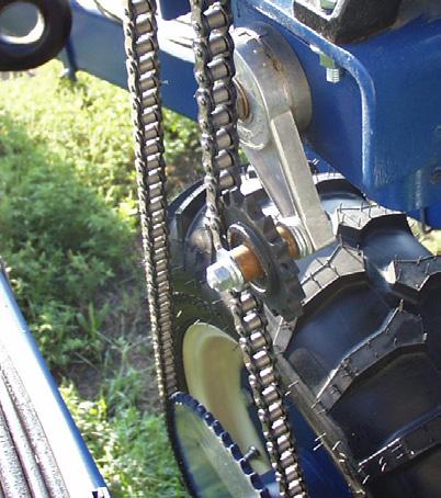
Radial loads are generated when force is applied perpendicular to the centerline of the shaft and are frequently associated with pin or axle connections (see illustration below). Fenner Industrial Motion Keyless Bushings are well suited to provide tight, backlash-free connections for this type of application, as explained below.
Frad = radial load capacity = d × L × Ps
where: d = shaft diameter
D = hub bore
L = contact length
Ph = hub pressure
Ps = shaft contact pressure = Ph × D d
Typical pressure distribution in backlash-free pin connections
d = pin diameter
pmin. =p - pL
0 pmax. = p + pL
Y.P.
Explanations: p = contact pressure provided by keyless bushing
= contact pressure on projected contact area


Fenner Industrial Motion Keyless Bushings transmit torque and other loads by means of mechanical interference generated by pressure exerted on both the shaft and mounted component hub. Therefore, consideration must be given to the amount of hub material (wall thickness) required to prevent permanent expansion (i.e., yielding). The following information is provided to assist you in determining the required hub diameter DN for any keyless bushing application.
Following standard industry practice, the criterion σti < Sy is used to determine DN as follows:
DN = D Sy + (Ph × C)
Sy - (Ph × C)
where: D = hub bore diameter (from product specifications)
Ph = contact pressure applied to hub bore (from product specifications)
Sy = yield strength of hub material and C = Stress Reduction Factor which assumes the value of 1.0, 0.8 or 0.6 depending upon the relationship of your actual hub width Hw to the contact length L of the keyless bushing selected. Use the illustrations on the right to determine C for your application.

THICK WALLED CYLINDER
SUBJECTED TO INTERNAL PRESSURE
TANGENTIAL STRESSES “st“
RADIAL STRESSES “sr“
EXPANSION/CONTRACTION
THICK WALLED CYLINDER
SUBJECTED TO EXTERNAL PRESSURE
TANGENTIAL STRESSES “st“
RADIAL STRESSES “sr“
EXPANSION/CONTRACTION
= T 12
i = inside of cylinder
o = outside of cylinder KEY
COMBINED HUB STRESSES
ν = Poisson’s ratio for steel: 0.29
E = modulus of elasticity for steel: 3.0 × 10 7 psi (2.07 × 10 5 N/mm2)
P = pressure
τ = torsional hub stress
T = Applied Torque
Trantorque OE 1", assuming a 2" wide hub made of 55,000 psi yield strength material .
Locate part number 6410100 on page 18.
Record the values for outside diameter D, contact length L, and hub pressure Ph and return to this page.
D = 1½"
L = 1"
Ph = 19,639 psi
Determine the Stress Reduction Factor C, by first calculating the ratio of hub width to contact length (Hw /L). Next, locate the appropriate product line in Table 1 on previous page to determine C.
NOTE: Contact Fenner Industrial Motion Technical Services if
The last item required is the yield strength of your mounted component, Sy . This value should be obtainable from the manufacturer of the mounted component or raw material supplier. For this example, the yield strength is 55,000 psi.
Substitute the values obtained above into the minimum hub diameter equation, DN to obtain your result.
55,000 + (19,639 × 0.6)
DN = 1.5 = 1.865"
55,000 - (19,639 × 0.6)
Above Example Your Example
Series Trantorque OE
Part Number 6410400
Size 1"
Outside diameter, D 1.5
Contact Length, L 1
Hub Pressure, Ph 19,639
Hub Size, Hw 2"
DN = D Sy + (Ph × C) Sy - (Ph × C)
Yield Strength, Sy 55,000 psi = 2 C = 0.6 Hw L < 1 Hw L = 1.5 = 1.865"
55,000 + (19,639 × 0.6)
55,000 - (19,639 × 0.6)
C is obtained from Table 1 on previous page for Trantorque where ≥ 2 Hw L = 2 = C = 0.6 2 1 Hw L = = C = Hw L + ( × ) - ( × ) = =
DN = D Sy + (Ph × C) Sy - (Ph × C)
TOLERANCE (TL)
5/8 164 6282 14316
11/16 180 6282 14316
3/4 196 6282 14316
13/16 222 6554 10015
7/8 239 6554 10015 15/16 256 6554 10015
1 273 6554 10015
1 1/16 333 7524 8917
1 1/8 353 7524 8917
1 3/16 372 7524 8917
1 1/4 392 7524 8917
1 5/16 412 7529 5194
1 3/8 431 7529 5194
1 7/16 452 7529 5194
1 1/2 471 7529 5194
1 9/16 535 8219 4599
1 5/8 557 8219 4599
1 11/16 578 8219 4599
1 3/4 599 8219 4599
1 13/16 979 12963 5639
1 7/8 1013 12963 5639
1 15/16 1047 12963 5639
2 1080 12963 5639
2 1/16 1087 12650 4781
2 1/8 1120 12650 4781
2 3/16 1153 12650 4781
2 1/4 1186 12650 4781
2 5/16 1181 12260 4064
2 3/8 1213 12260 4064
2 7/16 1245 12260 4064
2 1/2 1277 12260 4064
2 9/16 1295 12127 3554
2 5/8 1326 12127 3554
2 11/16 1358 12127 3554
2 3/4 1390 12127 3554
2 13/16 1452 12394 3233
2 7/8 1485 12394 3233
2 15/16 1517 12394 3233
3 1549 12394 3233

The data in the Performance Data Table is for a steel unit. To obtain data for other materials, use the multiplier provided.
For example, you require a 2" (d) Electroless Nickel Plated Trantorque GT.
Find 2" (d) in Performance Data Table and use the multiplier of 0.6 for Electroless Nickel Plated Steel.
Mt : 1080 x 0.6 = 648 Th : 12963 x 0.6 = 7778 *Ph : 5639 x 0.6 = 3383
* IMPORTANT: After hub pressure (Ph) is determined, record D, L and Ph and refer to page 9 and 10 to calculate the minimum hub diameter.
Please note not all catalog items shown are stock. Some products are make-to-order (MTO) based on annual demand. Please verify with your customer service representative for current availability of the item desired.
Please note not


The data in the Performance Data Table is for a steel unit. To obtain data for other materials, use the multiplier provided.
For example, you require a 30mm (d) Electroless Nickel Plated Trantorque GT.
Find 30mm (d) in Performance Data Table and use the multiplier of 0.6 for Electroless Nickel Plated Steel.
Mt : 499 x 0.6 = 266 Th : 33 x 0.6 = 20
*Ph : 61 x 0.6 = 37
* IMPORTANT:
After hub pressure (Ph) is determined, record D, L and Ph and refer to page 9 and 10 to calculate the minimum hub diameter.

1/8
3/16
1/4
5/16
1608 18193
1608 18193
1608 18193
2584 20890
3/8 485 2584 20890 7/16 737 3368 20421
1/2 842 3368 20421
9/16 1223 4349 18459
5/8 1359 4349 18459 Performance Data
(continued on page 17)
Trantorque Mini Performance Data (continued from page 16)
The data in the Performance Data Table is for a steel unit. To obtain data for other materials, use the multiplier provided.
For example, you require a 1/4" (d) Electroless Nickel Plated Trantorque Mini.
Find 1/4" (d) in Performance Data Table and use the multiplier of 0.8 for Electroless Nickel Plated Steel.
Mt : 201 x 0.8 = 161
Th : 1608 x 0.8 = 1286
*Ph : 18193 x 0.8 = 14554

Trantorque Micro – Inch
* All Trantorque Micro orders are subject to a 25 piece minimum.
* IMPORTANT:
After hub pressure (Ph) is determined, record D, L and Ph and refer to page 9 and 10 to calculate the minimum hub diameter.
† When installing Trantorque Mini with an open-ended wrench, a reduction in installation torque by 50% is recommended. This will result in a Transmitted Torque (Mt) reduced by 50%.
Performance Data Table
166 5805 20843
3/4 181 5805 20843
13/16 241 7113 21014
7/8 259 7113 21014
15/16 311 7963 19639
1 332 7963 19639
1 1/16 364 8224 17211
1 1/8 386 8224 17211
1 3/16 431 8712 15664
1 1/4 454 8712 15664
1 5/16 489 8938 14004
1 3/8 512 8938 14004
1 7/16
The data in the Performance Data Table is for a steel unit. To obtain data for other materials, use the multiplier provided.
For example, you require a 1" (d) Electroless Nickel Plated Trantorque OE.
Find 1" (d) in Performance Data Table and use the multiplier of 0.6 for Electroless Nickel Plated Steel.
Mt : 332 x 0.6 = 199 Th : 7963 x 0.6 = 4778 *Ph : 19639 x 0.6 = 11783
* IMPORTANT:
After hub pressure (Ph) is determined, record D, L and Ph and refer to page 9 and 10 to calculate the minimum hub diameter.
8336 11469
8336 11469 1 1/2
† When installing Trantorque OE with an open-ended wrench, a reduction in installation torque by 50% is recommended. This will result in a Transmitted Torque (Mt) reduced by 50%.
Please note not all catalog items shown are stock. Some products are make-to-order (MTO) based on annual demand. Please verify with your customer service representative for current availability of the item desired.


The data in the Performance Data Table is for a steel unit. To obtain data for other materials, use the multiplier provided.
For example, you require a 20mm (d) Electroless Nickel Plated Trantorque OE.
Find 20mm (d) in Performance Data Table and use the multiplier of 0.6 for Electroless Nickel Plated Steel.
Mt : 315 x 0.6 = 189
Th : 32 x 0.6 = 19
*Ph : 144 x 0.6 = 86
* IMPORTANT:
After hub pressure (Ph) is determined, record D, L and Ph and refer to page 9 and 10 to calculate the minimum hub diameter.
†
Please note not all catalog items shown are stock. Some products are maketo-order (MTO) based on annual demand. Please verify with your customer service representative for current availability of the item desired.

*IMPORTANT: Please refer to page 9 and 10 to calculate your minimum hub diameter. Consult factory for weights and availability.


Locking screws transfer to integrated push-off holes for disassembly.
Metric socket head locking screws ISO 4762 grade 12.9 (See Ma for install torque).
Screw head height = screw diameter (mm)
Please note not all catalog items shown are stock. Some products are make-to-order (MTO) based on annual demand. Please verify with your customer service representative for current availability of the item desired.

locking screws ISO 4762 grade 12.9 (See Ma for install torque).
Please
TOLERANCE (TL)
Bore diameter machined to D -0/+TL
TL = .05mm for bores up to 120mm .08mm for bores up to 305mm .10mm for bores over 305mm
d = Shaft diameter machined to d +0/-TL

Locking screws transfer to integrated push-off holes for disassembly.
Metric socket head locking screws ISO 4762 grade 12.9 (See Ma for install torque).
TOLERANCE (TL)
Please note not all catalog items shown are stock. Some products are make-to-order (MTO) based on annual demand. Please verify with your customer service representative for current availability of the item desired.
Bore diameter machined to D -0/+TL
TL = .05mm for bores up to 120mm .08mm for bores up to 305mm .10mm for bores over 305mm
d = Shaft diameter machined to d +0/-TL
Note: Series B106 also available with optional integrated spacer sleeve (ideal for very narrow drive elements). Spacers are 0.275" wide for B106 sizes with D = 2.559" (65mm) and smaller, and 0.315" wide for all others.
Please note not all catalog items shown are stock. Some products are make-to-order (MTO) based on annual demand. Please verify with your customer service representative for current availability of the item desired.

Locking screws transfer to integrated push-off holes for disassembly.
Metric socket head locking screws ISO 4762 grade 12.9 (See Ma for install torque).
Please note not all catalog items shown are stock. Some products are make-to-order (MTO) based on annual demand. Please verify with your customer service representative for current availability of the item desired.
Bore diameter machined to D -0/+TL
TL = .05mm for bores up to 65mm .08mm for bores over 65mm
d = Shaft diameter machined to d +0/-TL

Metric socket head locking screws ISO 4762 grade 12.9 (See Ma for install torque).
Please note not
Screw head height = screw diameter (mm)
TOLERANCE (TL)
TOLERANCE (TL)
Bore diameter machined to D -0/+TL TL = .05mm for bores up to 50mm .08mm for bores up to 120mm .10mm for bores up to 235mm .13mm for bores up to 375mm
B-LOC pilot bushings: for series B400 Keyless Bushings to provide precentering in applications with either straight through hub bores or narrow hubs. Pilot bushings are supplied in sets consisting of three (3) bushings and three (3) longer screws (replacing plated locking screws). For more information refer to www.fenner.com or contact Technical Services at AE@fenner.com.
Recommended pre-centering length in installations without pilot bushings. Provide a minimum .001" clearance (hub concentricity depends on fit clearance).
.15mm for bores over 375mm
d = Shaft diameter machined to d +0/-TL
Please note not all catalog items shown are stock. Some products are make-to-order (MTO) based on annual demand. Please verify with your customer service representative for current availability of the item desired.

Locking screws transfer to integrated push-off holes for disassembly.
Metric socket head locking screws ISO 4762 grade 12.9 (See Ma for install torque).
Screw head height = screw diameter (mm)
Please note not all catalog items shown are stock. Some products are make-to-order (MTO) based on annual demand. Please verify with your customer service representative for current availability of the item desired.
TL = .05mm for bores up to 120mm .08mm for bores up to 305mm .10mm for bores up to 635mm .13mm for bores over 635mm
d = shaft diameter machined to d +0/-TL TOLERANCE (TL)


Please note not all catalog items shown are stock. Some products are make-to-order (MTO) based on annual demand. Please verify with your customer service representative for current availability of the item desired.
Inch and Metric

Locking screws transfer to integrated push-off holes for disassembly.
Metric socket head locking screws ISO 4762 grade 12.9 (See Ma for install torque).
TOLERANCE (TL)
TL = .05mm for bores up to 120mm .08mm for bores up to 305mm .10mm for bores up to 635mm .13mm for bores over 635mm d = shaft diameter machined to d +0/-TL
Please note not all catalog items shown are stock. Some products are make-to-order (MTO) based on annual demand. Please verify with your customer service representative for current availability of the item desired.

Locking screws transfer to integrated push-off holes for disassembly.
Metric socket head locking screws ISO 4762 grade 12.9 (See Ma for install torque).
Please

Metric socket head locking screws ISO 4762 grade 12.9 (See Ma for install torque).
Additional sizes available upon request.
Please note not all catalog items shown are stock. Some products are make-to-order (MTO) based on annual demand. Please verify with your customer service representative for current availability of the
T = peak drive torque = nominal torque multiplied by a safety factor to account for stall or start-up conditions, mass accelerations, impact loads, etc. Nominal drive torque can be calculated as follows:
Mtnom (ft lb) = 5252 × HP rpm
The mounted component’s bore matches the pilot diameter to maximize concentricity.
B-LOC Compression Hubs differ from other keyless locking devices in how they engage the mounted component. Rather than creating a radial force on the mounted component, the outer tapered rings are drawn together to generate an axial clamping force. In this way, the mounted component is not subjected to tensile (hoop) stresses. This operating principle also allows narrow components to be mounted with excellent runout.
Recommended surface finish for shafts to be used with B-LOC Compression Hubs is between 32 and 125 microinch (0.8 and 3.2 micrometer) RMS. A smoother finish — such as that found on components supplied TG&P (turned, ground and polished) — is NOT recommended and can result in a failure of the connection. Note that surface finishes below 32 microinch (0.8 micrometer) RMS can be roughened using longitudinal abrasion with a bastard file, emery paper or similar to achieve a surface finish within the recommended range. The recommended surface finish on the contact faces of the mounted component is between 32 and 250 microinch (0.8 – 6.4 micrometer).
Fenner Industrial Motion Keyless Locking Devices are precision machined to maximize concentricity and minimize runout. The final installed concentricity of mounted components depends on several variables, including the components themselves and the installation technique employed. In the case of B-LOC Compression Hubs, total runout can be minimized by machining the bore and contacting faces of the mounted component to tight tolerances.
B-LOC Keyless Locking Devices are supplied with an oil specific to the product line. The listed performance data requires the use of these lubricants to provide the necessary coefficient of friction to the sliding surfaces. Likewise, do not use anaerobic adhesives such as Loctite, Permatex or similar compounds with Fenner Industrial Motion Keyless Locking Devices. Doing so results in unknown contact pressures and capacities. Furthermore, disassembly may be compromised when such compounds are applied to the keyless bushing, the shaft and/or the hub bore. The approved lubricant for use with B-LOC Compression Hubs is CRC3-36.
B-LOC Keyless Locking Devices are made from carbon steels and heat treated alloy steels. For applications in corrosive environments, corrosion resistance can be improved through sealing with grease or silicone, the use of protective cover plates, application of industry standard plating materials (e.g., nickel, thin dense chrome, etc.) or by specifying the product in stainless steel or other corrosion resistant materials. Please consult with a Fenner Industrial Motion Applications Engineer for more details.
Mtnom (Nm) = 9550 × kW rpm
Consult with a Fenner Industrial Motion Applications Engineer in cases where “T” is uncertain.
Mt = The rated torque capacity of one Fenner Industrial Motion Keyless Locking Device installed according to our instructions. Published torque capacities are calculated without using a safety factor and should be considered as the point where a connection could slip if a higher torque is applied. Therefore, always select a unit where Mt ≥ T.
B-LOC Compression Hubs offer a unique design that can provide solutions for applications beyond the standard, single chain sprocket application. Because compression hubs function by clamping the mounted components in the axial direction, cost savings can be realized by stacking together lower cost individual components. The compression hub simultaneously clamps the assembly together and attaches the assembly to the shaft.


A
Applications that require spacing between thin end discs can be accommodated by extending the pilot surface through the end discs so that it engages a spacer and keeps the entire assembly aligned.
Split sprocket designs are simplified by utilizing an A-plate sprocket which is split in a way that provides positive engagement between the two halves.

TOLERANCE (TL)
Recommended bore diameter d1 +.03mm / +.08mm
TL = .05mm for shafts up to 75mm
Shaft diameter machined to d +0/-TL
Parallelism machined to X +/- 0.13mm
Contact Technical Services:
• Larger and smaller bore sizes available upon request
• Larger mounted component thickness (outside of X Ranges 1 and 2) can be easily accommodated. Fully-threaded screws are required for mounted component thicknesses larger than X Range 2.
• Fenner Industrial Motion can engineer a custom B-LOC Compression Hub to meet your needs.
• Email: AE@fenner.com
Please note not all catalog items shown are stock. Some products are make-to-order (MTO) based on annual demand. Please verify with your customer service representative for current availability of the item desired.

TOLERANCE (TL)
Recommended bore diameter d1 +.03mm / +.08mm
TL = .05mm for shafts up to 75mm
Shaft diameter machined to d +0/-TL
Parallelism machined to X +/- 0.13mm
Contact Technical Services:
• Larger and smaller bore sizes available upon request
• Larger mounted component thickness (outside of X Ranges 1 and 2) can be easily accommodated. Fully-threaded screws are required for mounted component thicknesses larger than X Range 2.
• Fenner Industrial Motion can engineer a custom B-LOC Compression Hub to meet your needs.
• Email: AE@fenner.com
Please note not all catalog items shown are stock. Some products are make-to-order (MTO) based on annual
External locking devices for keyless frictional shaft/hub connections on shafts from 5/8" to 40" diameter, B-LOC Shrink Discs…
• Provide a high capacity interference fit with all the positive features of conventional interference fits, but without their assembly and disassembly problems.
• Offer extremely concentric and well-balanced connections, ideal for high-speed applications.
• Permit simple axial positioning and angular timing.
• Are available in standard, light, and heavy-duty series to suit any application.
B-LOC Shrink Discs provide a high-ratio conversion of screw clamp loads into radial contact pressures when the tapered collars are pulled together by tightening of the integrated high-strength locking screws. These radial contact pressures in turn accomplish the following:
1. Contract the inner ring and hub to close the clearance between shaft and hub bore.
2. Generate a defined shaft/hub contact pressure for a high capacity mechanical interference fit.
This frictional bond transmits torque, bending and/or thrust loads directly from the hub to the shaft; the shrink disc itself does not carry any torque or thrust load.
Mt = rated torque capacity of one B-LOC Shrink Disc with all screws tightened to specified torque Ma as listed in specifications, based on a coefficient of friction μ = 0.15 and specified tolerances and clearances. Torque capacities for Half Shrink Discs = Mt
• Torque capacities for connections using shaft diameters between the minimum and maximum sizes listed can be approximated through interpolation.
• Transmissible torque decreases if tolerances and/or clearances are larger than specified; or if hollow shafts with bores exceeding approximately 35% of shaft diameter are used.
Th = transmissible thrust, determined by using the following equation:
Th = 2 × Mt
d where: d = shaft diameter
Mt = rated torque capacity
Simultaneous transmission of torque and thrust requires calculating a resultant torque:
Mtres =
where: T = peak drive torque
F = peak thrust load
d = shaft diameter
Select a unit where Mt ≥ Mtres
Shrink discs will generally transmit a continuous bending moment equal to 25% of rated torque capacity Mt
Since the tapers of a B-LOC Shrink Disc are self-releasing and stresses from radial contractions of the hub are well within elastic limits, loosening the locking screws results in hub expansion back to its original dimensions, thereby restoring fit clearance for simple disassembly. The SD40 is manufactured with self-releasing tapers, however, it is possible the outer ring may need disengaging from the inner ring. This can be easily done by loosening the bolts in sequence, transferring the appropriate number of bolts over to the threaded back-off holes in the face of the shrink disc and progressively tightening these bolts until the shrink disc becomes loose. The hub and shaft will return to their original fit clearances.
Shrink disc inner rings are manufactured from high-carbon steel. Outer rings are made from forged and heat treated alloy steel.
Shrink discs are supplied with Molybdenum Disulphide based lubricant applied to the tapers and to the locking screw threads and head contact areas.
Listed specifications assume shaft and hub material with a yield point of at least 45 ksi (310 N/mm2). Cast iron hubs are well suited for compressive stresses exerted by B-LOC Shrink Discs. However, a lower torsional hub strength generally requires the selection of a shrink disc at least one size larger than listed if full torque (i.e., that applicable to a steel hub) is to be transmitted.
The most recent research on length of fit for a shrink disc connection* indicates that the hub bore-to-shaft interface should be relieved using a non-toleranced clearance except for that portion directly under the shrink disc inner ring, for a fit length equal to “L” for a standard shrink disc (see illustration at right). This approach eliminates fretting corrosion between shaft and hub which can make the separation of components difficult.
*(see Casper, Thomas: Reibkorrosionsverhalten von Spanelementverbindungen - Aachen: Mainz, 1999)
In applications subjected to reversing bending moments, we recommend the configuration at right which requires a hub undercut where R ≥ e for smooth transition.


Notes:
• Inner rings of all shrink discs are supplied with one lengthwise slit.
• Shrink discs are available for shafts up to 40" diameter and in a variety of special designs.
• Maximum shaft sizes listed for Shrink Disc Series SD10 and SD30 reflect equal section moduli of shaft and hub (maximum shaft diameter = ).
• Larger shrink discs for shafts up to 40" diameter are available on request. d 1.221
Please note not all catalog items shown are stock. Some products are make-to-order (MTO) based on annual demand. Please verify with your customer service representative for current availability of the item desired.
Shrink Disc
Shrink Disc
Notes:
• Inner rings of all shrink discs are supplied with one lengthwise slit.
• Shrink discs are available for shafts up to 40" diameter and in a variety of special designs.
• Maximum shaft sizes listed for Shrink Disc Series SD10 and SD30 reflect equal section moduli of shaft and hub (maximum shaft diameter = ).
• See Table 1 (bottom of page 42) for maximum diametrical clearance between shaft and hub bore.
Please note not all catalog items shown are stock. Some products are make-to-order (MTO) based on annual demand. Please verify with your customer service representative for current availability of the item desired.
Notes:
• Inner rings of all shrink discs are supplied with one lengthwise slit.
• Shrink discs are available for shafts up to 40" diameter and in a variety of special designs.
• Maximum shaft sizes listed for Shrink Disc Series SD10 and SD30 reflect equal section moduli of shaft and hub (maximum shaft diameter = ).
• See Table 1 (bottom of page 43) for maximum diametrical clearance between shaft and hub bore.
Please note not all catalog items shown are stock. Some products are make-to-order (MTO) based on annual demand. Please verify with your customer service representative for current availability of the item desired.
To complement our standard line of B-LOC Shrink Discs, we also offer Split and Half Shrink Discs. These versions are available in all bore sizes listed for standard Shrink Discs. The Split Shrink Disc design allows greater mounting versatility on symmetrical hubs. For applications with tight space constraints and lower performance requirements, Half Shrink Discs provide several compact mounting options.
• Reduced dimensions – Perfect for applications with restricted space.
• Easy Installation – Standard screws mean installation and removal are achieved using standard tools.
• Infinite Adjustment – Simplified design allows hubs to be located and locked virtually anywhere on the shaft.
• Easy Removal – Units are self-releasing once the locking screws are loosened, making removal a breeze.
• Reliability you can count on – B-LOC Shrink Discs can be tightened and released as often as required.
Note: Dimension X is required when ordering Split or Half Shrink Disc Type HT. See Table 1 at bottom left of page 46 for web clearance hole data. Please consult B-LOC Technical Services at AE@fenner.com to determine appropriate screw length for your specific application.
Split Shrink Discs
Standard and Light Duty Series: If dimension X > 2 × L then the transmissible torque may be reduced by up to 50%. Heavy Duty Series: If dimension X > 1 × L then the transmissible torque may be reduced by up to 50%.
Half Shrink Discs
Half Shrink Discs HC/HT transmit 50% of the Mt of Shrink Discs and Split Shrink Discs.
Detail A
Dimension X is required when ordering Split Shrink Discs. See Table 1 at bottom left for web clearance hole data.
1
Notes:
•
• Shrink discs are
• Larger shrink discs for shafts up to 40" diameter are
Please note not all catalog items shown are stock. Some products are maketo-order (MTO) based on annual demand. Please verify with your customer service representative for current availability of the item desired.
• Type HT: Screw length must be determined based on your X dimension. Please consult Technical Services.
• Inner rings of all shrink discs are supplied with one lengthwise slit.
• Shrink discs are available for shafts up to 40" diameter and in a variety of special designs.
• Maximum shaft sizes listed for Shrink Disc Series SD10 and SD30 reflect equal section moduli of shaft and hub (maximum shaft diameter = ).
• Larger shrink discs for shafts up to 40" diameter are available on request. d 1.221
Please note not all catalog items shown are stock. Some products are maketo-order (MTO) based on annual demand. Please verify with your customer service representative for current availability of the item desired.
For
Table 1
Notes:
• Type HT: Screw length must be determined based on your X dimension. Please consult Technical Services.
• Inner rings of all shrink discs are supplied with one lengthwise slit.
• Shrink discs are available for shafts up to 40" diameter and in a variety of special designs.
• Maximum shaft sizes listed for Shrink Disc Series SD10 and SD30 reflect equal section moduli of shaft and hub (maximum shaft diameter = ).
• Larger shrink discs for shafts up to 40" diameter are available on request. d 1.221
Please note not all catalog items shown are stock. Some products are maketo-order (MTO) based on annual demand. Please verify with your customer service representative for current availability of the item desired.
Please note not all catalog items shown are stock. Some products are make-to-order (MTO) based on annual demand. Please verify with your customer service representative for current availability of the item desired.
Please note not all catalog items shown are stock. Some products are make-to-order (MTO) based on annual demand. Please verify with your customer service representative for current availability of the item desired.
We also offer SD40 Single Taper Shrink Discs as an alternative to SD10, SD20 & SD30 Double Taper Shrink Discs. The SD40 units have the following attributes:
• External locking device
• Simpler two piece design
• Integrated removal holes
• Provides extremely concentric and well-balanced mechanical interference fit
The advantages of the SD40 over the SD10, SD20 and SD30 include:
• No torque wrench needed.* Simply tighten the screws in clockwise sequence, using several passes, until the front faces of the flange and of the outer ring are aligned
• Save up to 80% of mounting time if using a powered tool
• High transmissible torque
• Aligning the two flanges (flush mounted) ensures concentricity, reducing the need for dynamic balancing
Note: Dynamic fit pressures vary between Single Taper and Double Taper shrink discs, as this is based on effective contact length. This should be taken into consideration.
* A torque wrench is recommended for best performance.
For assistance or more information on B-LOC Single Taper Shrink Discs, contact Fenner Industrial Motion Technical Services group at AE@fenner.com.

Metric hex head locking screws ISO 4017 grade 12.9 (See Ma for install torque.)
Shrink Disc
Inch
External keyless locking devices that simultaneously transmit high torques and bending moments that allow your drive to be overhung shaft mounted.
• Keyless, rigid, zero backlash coupling
• Transmits high torque and bending moments.
• Eliminates the need for costly mounting brackets and structural support
• Compact, double taper design with self-releasing tapers for easy removal
• Exceptional concentricity.
• Installs right over existing keyways and splines.
• Not affected by shock or reversing loads.
Drawing the two tapered collars together with the integrated tightening screws, generates radial forces that squeeze the inner ring tightly to the two shafts. The inner ring acts as a press fit sleeve, transmitting torque, thrust, and even bending loads from one shaft to the other.
Mt = rated torque capacity of one B-LOC WK Coupling with all screws tightened to specified torque Ma as listed in specifications.
Th = transmissible thrust, determined by using the following equation:
Th = 2 × Mt d
where: d = shaft diameter Mt = rated torque capacity

Simultaneous transmission of torque and thrust requires calculating a resultant torque:
Mtres =
where: T = peak drive torque
F = peak thrust load
d = shaft diameter
Select a unit where Mt ≥ Mtres
WK Couplings will generally transmit a continuous bending moment equal to 25% of rated torque capacity Mt.
Since the tapers of a B-LOC WK Coupling are self-releasing, loosening the locking screws results in releasing the shafts from the coupling. Care needs to be used by loosening each screw gradually such that the screw tension remains relatively equal on all screws.
WK Coupling inner rings are manufactured from high-carbon steel. Outer rings are made from forged and heat treated alloy steel.
WK Couplings are supplied with molybdenum disulphide based lubricant applied to the tapers and to the locking screw threads and head contact areas. The bore of WK Couplings are supplied lightly oiled and should only be used with oil supplied on the unit.
Listed specifications assume shaft material with a yield point of at least 45 ksi (310 N/mm2).
Shaft engagement inside the WK Coupling must be equal for both shafts and the gap between the shafts should not exceed 5% of the shaft diameter.

Requires bulky frame work and supports
Shaft misalignment issues necessitate the use of flexible couplings
Fretted and corroded flexible couplings complicate disassembly
Higher total cost
MOUNTED (flexible coupling)


MOUNTED (WK Coupling)
Shaft mount completely eliminates shaft misalignment and frame work
Simple torque arm prevents motor rotation
Keyless mechanical shrink fit never corrodes to the shaft and disassembles easily

Compact design allows for smaller drive footprint Lower overall cost

Once you have selected your WK Rigid Coupling, apply the following calculations to verify that it is suitable for your application. Please reference Plan View above.
1. Mt = published max rated torque capacity of B-LOC WK Rigid Coupling = ______ ft-lb
2. MDMAX = maximum drive torque (stall torque where applicable) = ______ ft-lb
3. W = weight of the overhung shaft mounted drive = ______ lb
4. R = length of the torque arm = ______ ft
5. FTA = torque arm reaction force = MDMAX ÷ R = ______ lb
6. MB = bending moment at the coupling NOTE: MB must be <0.25 × Mt TORQUE ARM OPTIONS
Straight Torque Arm
MB = (W × X1) + (FTA × X2) = ______ ft-lb
Bent Torque Arm
MB = (W × X1) + (FTA × X3) = ______ ft-lb
Double Torque Arm
MB = (W × X1) = ______ ft-lb
7. MtB = resultant (torque & bending) = (MDMAX)2 + (2 × MB)2 = ______ ft-lb
NOTE: MtB must be <Mt
8. If the NOTES in steps 6 and 7 are both satisfied, the B-LOC WK Rigid Coupling is recommended for your application.
• For any WK Coupling design or engineering questions, contact a Fenner Industrial Motion Applications Engineer at AE@fenner.com.
• Shaft mounting creates bending moments in the system; coupling, shafts, bearings etc., must be designed to handle these bending moments.
• Torque arm design and placement can be used to counteract or minimize bending moments in the system.
• Torque arm and arm stop(s) must be adequately designed to handle the forces generated by the motor.
• To achieve up to a 20% increase in coupling load capacity, using a nonpetroleum based solvent, clean the shafts and coupling bore to produce a completely lubricant free interface.
• WK Couplings can typically join shafts of different sizes up to a ratio of 2:1. For shaft ratios greater than this, please contact a Fenner Industrial Motion Applications Engineer.
• WK Couplings are not recommended for applications in which motor and driven component are rigidly mounted.

Metric hex head locking screws grade 10.9. (See Ma for install torque.)
If your application requires increased torque transmission and/or thrust, solvent clean the interface between the bore of the WK unit and the shaft to produce an oil free connection. This in turn will result in up to a 20% increase in Mt and Th performance values. Contact Fenner Industrial Motion Technical Services for additional details at AE@fenner.com.
TOLERANCE (TL)
Shaft
equal for
Please note not all catalog items shown are stock. Some products are make-to-order (MTO) based on annual demand. Please verify with your customer service representative for current availability of the item desired.
If your application requires increased torque transmission and/or thrust, solvent clean the interface between the bore of the WK unit and the shaft to produce an oil free connection. This in turn will result in up to a 20% increase in Mt and Th performance values. Contact Fenner Industrial Motion Technical Services for additional details at AE@fenner.com.


Our molded, composite portfolio includes essential products such as Fenner Drives tensioners, pulleys & idlers and Bearings pillow blocks, thrust bearings, radial bearings, washers, and retainers. These products cover a wide range of markets including:
• Automotive
• Data Centers
• Distribution Centers
• Livestock Farming
• Fitness
• Glass
• Gypsum
• HVAC
• Meat Processing
• Packaging
• Power Tools
• Tile
• Wood Processing And many others.
While we have an extensive inventory of in stock parts, our engineering team specializes in developing custom designs to fit your application needs. Contact Engineering at 1-800-243-3374.


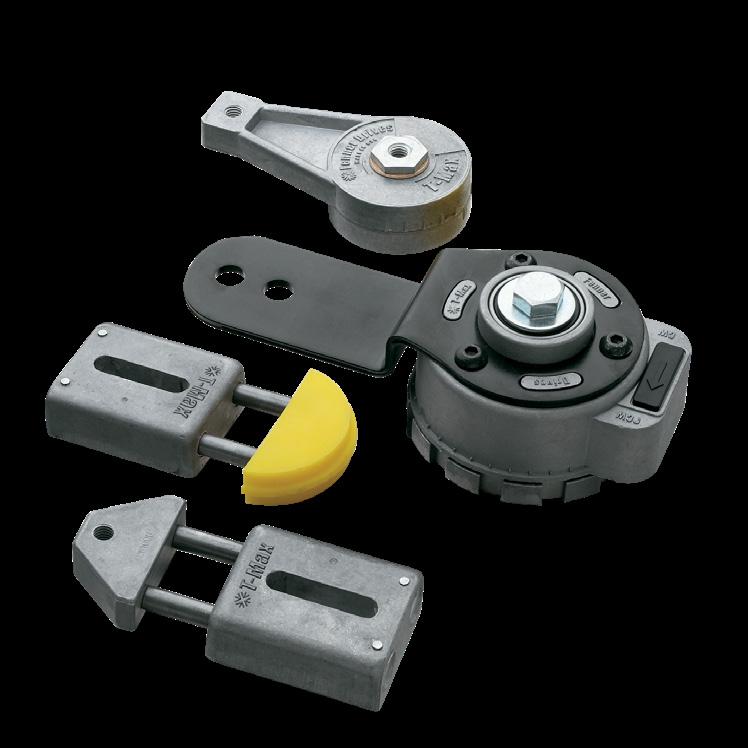
Automatically take up the slack and avoid the risk of over-tensioning drive components to enhance overall drive operating efficiency.
• Constructed from high-quality materials for proven durability
• Wide range of tensioners to handle single and multiple strand belt and chain drives
• Available in linear and rotary (light-duty, medium and heavy-duty) series
• A range of sizes and mounting styles available to best fit your application
Fenner Drives has proven success in these Markets:
• Data Centers
• Distribution Centers
• Livestock Farming
• Glass
• Gypsum
• HVAC
• Meat Processing
• Packaging
• Wood Processing

RT1000 Series *
RT1600 Series *
RT3000 Series *
* Maximum load no more than 1½” distance from front face of tensioner arm to centerline of idler.
† Requires a fixed head, hook style spanner wrench for tensioning (supplied with unit).
‡ Dimension A: 1° rotation = .83 lb. force.
Dimension A1: 1° rotation = 1 lb. force. All forces (lbs.) are nominal.
§ 1° rotation = .83 lb. force. All forces (lbs.) are nominal.

* Consult factory for minimum orders and lead times


Fenner Industrial Motion is the industry leader in molded composite solutions for industrial power transmission and material handling applications. Fenner Drives composite products are used where dependability counts most.
• High-strength glass reinforced composite idlers and pulleys are available in a wide range of sizes for flat, round and V-belts.
• Our composite products are a lightweight, corrosion resistant alternative to steel, aluminum and cast iron.
Fenner Drives has a strong history in the following Markets:
• Data Centers
• Distribution Centers
• Livestock Farming
• Fitness
• HVAC
• Packaging
• Tile

Almost all Fenner Drives Pulleys use precision 6203-2RS chrome-alloy steel radial ball bearings (exceptions are noted). These bearings meet all ABEC-1 standards. Our bearings utilize two rubber wiping seals to keep the grease in and contaminants out. See chart for standard load ratings.
How long a bearing will last in an application depends on two variables: first, the bearing’s physical properties (material, design, method of manufacture); and second, the conditions of operation (load, speed, temperature, lubrication). Although it is not possible to predict the exact life of a bearing, the designer can calculate the “L10 Life” of a bearing. L10 is the life, in hours or revolutions, that 90% of a group of bearings will complete or exceed. The equations for calculating L10 life are:
Fenner Industrial Motion uses engineering composites, which ensure the highest level of performance and consistent strength. Our standard material is 33% glass reinforced nylon 6/6. The combination of high strength, temperature resistance and abrasion resistance makes nylon a versatile engineering thermoplastic.
Data listed was generated using molded specimens tested under standard conditions. Many of the mechanical properties can be influenced by processing conditions, environmental factors and the application of stress. Therefore, this data characterizes typical production material, and should not be used either to establish specification limits or alone as the basis for engineering design.


Sprocket
Mounting adapters are for use with PoweMax products and are not sold individually . Consult factory for min orders and lead times .


Composite pillow block bearings designed to perform like metal.
• Benefits of composite in the housing
• Industry standard dimensions
• Custom designs for OEMS available

Custom thrust bearings, radial bearings, angular contact bearings, subassemblies and bearing components
• An industry leading brand that is manufactured in the U.S.
• Custom bearings for a range of applications from power tools to transportation that are designed to fit precise space requirements, performance needs, environmental conditions and all quality specifications
• Expertise in CNC machining, injection molding, stamping and assembly to provide subassemblies
• Services to design, manufacture and assemble the right bearing for the specific application
Fenner Drives Bearings products are found in these Markets:
• Appliances
• Automotive
• Fitness
• HVAC
• Medical Devices
• Power Tools and Equipment

Basic Dynamic Load Rating: 3145 lbf Static Load Rating: 1750 lbf
NOTE: Also available in the following bore sizes 7/8”, 15/16” and 25mm as a
catalog item. Consult factory for minimum orders and lead times
** Dimension (B) is the hole center distance, (A) is the hole diameter

NOTE: Consult factory for minimum orders and lead times
Our custom bearing assemblies are manufactured to meet your application’s specific needs. Every feature of a bearing assembly can be customized to maximize the benefit to your product. By working with your engineering department from the start, collaborating throughout the design, prototyping and manufacturing processes and delivering your orders on time, Fenner Drives Bearings can guarantee quality, performance and your satisfaction.


Fenner Drives Bearings has an engineering department with decades of experience in bearing and assembly design. Our engineers have designed thousands of bearing assemblies and components in nearly 100 years of manufacturing. We utilize the latest design technologies to develop the right combination of materials, processes and inspection techniques. As a result, we can work with your engineers to design a solution that will provide the ideal bearing assembly for your product.
Fenner Drives Bearings has a modern and fully integrated manufacturing facility capable of producing customized bearing assemblies and components. We have developed highly flexible and automated systems that enable us to meet any production volume. Our manufacturing capabilities include:
• Metal stamping presses
• Plastic injection and insert molding machines
• Multispindle and CNC screw machines
• Robotic assembly machines
• Finishing, inspection and packaging systems


Fenner Drives Bearings maintains a vigorous quality assurance program. Our quality system is ISO 2001:2015 registered. Our product manufacturing teams and support departments are dedicated to ensuring that your bearings are manufactured to your exacting specifications and shipped on time. Our customer service team is focused on providing you with a seamless and efficient buying experience.

• Excellent choice for consumer, commercial and light industrial applications
• Unground races in metal, plastic and insert molded combinations
• Infinite range of custom mounting choices

• Perfect for controlling precision ball and needle load distribution
• Retainer materials are selected to meet diverse environmental conditions
• Combine with thrust washers to create the ideal thrust bearing assembly

• Ideal in applications requiring combined radial and thrust loads
• Available in machined or stamped metal and injection molded designs
• Customized designs can accommodate additional functional features

• Preferred choice for light duty guide and track applications
• Rollers designed to meet custom performance requirements with engineered plastics
• Studs may be adapted to accommodate and simplify your assembly processes

• Custom engineered subassemblies expand your manufacturing capacity
• Reduces assembly, purchasing and inventory costs
• Reduces quality problems

• Custom designed to provide ball separation and uniform load distribution in precision bearings

• Highly effective solution for thrust races, spacers, wear plates and bearing load surfaces
• Application specific hardness and surface finishes ensure reliable performance
• Custom designs accommodate space limitations

• Combines thrust retainers and thrust washers into a single package
• Any combination of metal and engineered plastic components are available
• Significantly improves assembly error proofing

• Perfect solution for linear reciprocal motion applications
• Custom designed to provide ball separation and uniform load distribution
• Simplifies assembly operations

• Unique wraparound retainer design for angular contact applications
• One-piece assembly reduces installation time and labor

