

Quick Disconnect Couplings Master Catalog


This is part of our brand name library available at: www.HoseWarehouse.com/catalogs Warehouse HOSE Authorized Wholesale Distributor Bulk Pricing Trained Techs & Customer Supoort Quick Order Fulfillment Product Warranty Product Traceability Recall notification Page 1
Eaton Quick Disconnect Couplings – Customizing Solutions for the Future… Hydraulics and Beyond
For over 90 years, Eaton has continued to manufacture and supply the highest performing quick disconnect couplings globally for many different market segments including agriculture, construction, transportation, and fire and rescue just to name a few. Eaton’s quality and performance have never been compromised when it comes to engineering and manufacturing its full line of quick disconnect couplings. From traditional industry standards to custom couplings for the next generation of emerging markets and new advanced technologies, Eaton continues to provide quick disconnect coupling solutions to meet your demands.
Custom Design Capability – One Application at a Time
Eaton continues the tradition of developing custom quick disconnect couplings for customers that need a product to perform above and beyond industry standards. Whether it is a custom coupling for the world’s most powerful and sophisticated super computers that use electronic cooling or a self contained breathing apparatus coupling for first responders, Eaton has the ability to work directly with you on a solution. Contact Eaton to see how our dedicated and experienced design engineering team will work with you to develop a quick disconnect coupling solution.
EATON Quick Disconnect Couplings Master Catalog E-MEQD-CC001-E8 August 2017 2 Table
Contents
of
Safety Information 3 Fluid Compatibility 4 Pneumatic Couplings Selector Chart 67 Fluid Transfer and Hydraulic HK ISO 7241-1B Series Interchange 8 HKFR Series ISO 7241-1 BOP 17 560 0 ISO 7241-1 A Series Interchange 18 H50 00 Series 25 FF Series 34 MLFF Series 39 FFCup Series 41 FD96 Series 43 FD49 Series 45 MLDB Series 47 510 0 Series 49 FD85 Series 53 FD86 Series 55 W600 0 Series 57 HP3 Series 63 W5600 0 Series 64 FD35 Series 65 Pneumatic 10 00/400/500 Series 69 300 0/4000/5000/6000 Series 77 Auto-Flo 23/24 Series 87 Safeline Series 91 180/280 Series 92 10 0 Series 94 600/70 0 Series 96 2RL/3RL Series 101 Full-Bore Series 106 210/310 Series 108 Special Applications FD14 Series 111 FD17 Series 114 FD69 Series 115 FD83 Series 117 2HKIG/2HKIL Series 118 ST Series 121 Flo-Temp™ Series 125 Gas-Mate™ Series 128 Flex-Air™ Series 130 In-Line Check Valves 132 Diagnostic FS Flow Sensor Series 133 FD15 Series 134 FD90 Series 136 FF14802 Pressure Gauge Kit 138 Agriculture FD48 Series 140 FD72/76 Series 141 Refrigerant 540 0 Series 142 Part Number Index 147 Page 2
Safety Information for Eaton Quick Disconnect Couplings
1.0 General Instructions.
1.1 Sc ope. The scope of this safety bulletin is to warn against improper selection, use, installation, etc. of Eaton coupling products.
1.2 Dis tribution. A copy of this safety bulletin should be distributed to all individuals responsible for using and/or selecting Eaton coupling products.
1.3 Fa il-Safe. Design all systems and equipment for fail-safe operation such that failure of any component does not result in personal injury and/or property damage.
1.4 Us er Responsibility. It is the sole responsibility of the user to select and determine that the Eaton product is compatible with the end use application. The user is responsible for reading and following this safety bulletin as well as any instructions or literature on the Eaton product being used. The user must provide necessary product warnings for Eaton couplings products, used with systems or equipment, to the operators of the systems or equipment.
1.5 Us age with other Manufacturers’ Products. When using Eaton coupling products with other manufacturers’ adapters, hoses, etc., do not exceed the lowest pressure rating of any of the components being used or rupture may result.
2.0 Se lection of Eaton Couplings.
2.1 Pr essure. Ensure that the maximum operating pressure of the system or equipment does not exceed the rated operating pressure of the Eaton coupling product or rupture may result.
2.2 Fl uid Compatibility. Verify that all components (seals, metals, etc.) are compatible with the fluid being conveyed. Failure to do so may result in high speed fluid discharge and/or leakage of fluids which may be flammable, toxic, at extreme temperatures, or otherwise harmful.
2.3 Tem perature. Ensure that the maximum operating temperature of the system or equipment does not exceed the rated operating temperature of the Eaton coupling product (including seals) or rupture may result.
2.4 Co upling Size. Use properly sized couplings such that there is not a large pressure drop across them thus avoiding system damage due to excessive heat generation or failure of internal components.
2.5 Sl eeve Lock. Use sleeve locks or threaded couplings where there is the possibility of accidental disconnection. Failure to utilize sleeve locks or threaded couplings in these applications may result in hose whip, expelled components, high speed fluid discharge, system damage, or leakage of fluids which may be flammable, toxic, at extreme temperatures, or otherwise harmful.
2.6 Connect or Disconnect Under Pressure. If connection and/or disconnection of couplings under pressure is a requirement, only use couplings designed for connection/disconnection under pressure. Failure to utilize this type of coupling in that application may result in hose whip, expelled components, high speed fluid discharge, and/or system damage. Be certain not to confuse the rated operating pressure with the rated connect/disconnect under pressure.
2.7 Environment. Ensure that Eaton couplings are compatible with the surrounding environment. The surrounding environment may be heat, salt water, moisture, chemicals, and the like. Failure to protect against an adverse environment may cause system damage, premature failure, and/or leakage of fluids which may be flammable, toxic, at extreme temperatures, or otherwise harmful.
2.8 Ex ternal Loads. Avoid any external loads such as side loads, tensile loads, vibration, etc. Failure to do so may result in accidental disconnection, premature failure, system damage, and/or leakage of fluids which may be flammable, toxic, at extreme temperatures, or otherwise harmful.
2.9 We lding & Brazing. Extreme heating of plated products above +450°F (+232°C) such as welding, brazing, baking, etc., where the plating is burned off, may result in the release of deadly gases.
3.0 In stallation of Eaton Couplings.
3.1 Ins pection of Product. Prior to installation, ensure that the Eaton product meets all of the requirements of the system and/or equipment it is to be used on. Ensure you have the correct part number, function test the coupling by connecting it with a mating half. The function test should result in smooth, non-binding operation or premature failure may result.
3.2 C leanliness. Use end caps and plugs to reduce the risk of system contamination or damage to critical sealing surfaces. Failure to do so may result in leakage of fluids which may be flammable, toxic, at extreme temperatures, or otherwise harmful. Caps and plugs are not a secondary seal unless explicitly noted.
3.3 Loc ation. Place Eaton couplings in a safe location such as not to expose the user to personal injury (slippage, tripping, falling, etc.) during installation, connection, disconnection and maintenance.
4.0 Product Maintenance. A maintenance schedule should be put in place to ensure that Eaton couplings are functioning properly. Eaton is not responsible for product failures resulting from modification or improper maintenance.
4.1 In spection. Visually inspect to ensure that there is no leakage, cracked components, corrosion build-up, contamination build-up, wear, etc. If any abnormality is encountered, the coupling should be replaced immediately.
EATON Quick Disconnect Couplings Master Catalog E-MEQD-CC001-E8 August 2017 3
Page 3
Fluid Compatibility
This chart indicates the suitability of various elastomers and metals for use with fluids to be conveyed. It is intended for use with Eaton couplings and should not be used to determine compatibility for other products. It is intended as a guide only and is not a guarantee. Final selection of the proper seal or material of metal components is further dependent on many factors including pressure, fluid and ambient temperature, concentration, duration of exposure, etc.
How to Use the Chart
1. Both the elastomer and the metal must be considered when determining suitability of combination for a coupling.
2. Locate the fluid to be conveyed and determine the suitability of the elastomeric and metal components according to the resistance rating shown for each.
3. Dimensional and operation specifications for each coupling can be found on the catalog pages.
4. Information on seal options for couplings, and how to specify them, are shown in the respective sections of this catalog.
5. Be sure to check the table below for maximum operating temperature range of the elastomer desired.
6. For further details on the products shown in this catalog, and their applications, consult your Eaton Sales Representative or Eaton Technical Support.
7. Coupling component materials may differ from body material. Refer to specific catalog pages.
This charts below are intended for reference use only. The information in this chart pertains strictly to material compatibility and is not intended to be used as an application guide.
E=Excellent
G=Good
C=Conditional
U=Unsatisfactory
Seal Elastomer Data*
to +121°C)
Neoprene -65°F to +212°F (-54°C to +10 0°C)
EPDM (Ethylene -65°F to +300°F
Propylene Rubber) (-54°C to +149°C)
FKM -15°F to +40 0°F (-29°C to +204°C)
*For reference only, based on Eaton recommended temperatures.
**For seals not listed contact Eaton. Contact Eaton technical support for further information.
Resistance Rating Key
E = Excellent – Fluid has little or no effect
G = Good – Fluid has minor to moderate effect
C = Conditional – Service conditions should be described to Eaton for determination of suitability for application
U = Unsatisfactory
The differences between ratings “E” and “G” are relative. Both indicate satisfactory service. Where there is a choice, the materials rated “E” may be expected to give better or longer service than those rated “G”.
EATON Quick Disconnect Couplings Master Catalog E-MEQD-CC001-E8 August 2017 4
Max. Operation Seal Elastomer** Temperature Range
-40°F to +250°F (-40°C
Buna-N
Buna-N Neoprene EPDM FKM St eel Brass Stainless Steel Aluminum Buna-N Neoprene EPDM FKM St eel Brass Stainless Steel Aluminum Acetaldehyde U C C U G E E E Acetic Acid, 10% U U E G U U C C Acetic Acid, Glacial U U C U U U C C Acetone U U G U E E E E Acetophenone U U E U E E E C Acetyl Acetone U U G U U C C C Acetyl Chloride U U U E C C C U Acetylene (1) G U G E E E E E Air, Hot (Up to +160°F) E E E E E E E E Air, Hot (161°F – 200°F) C G E E E E E E Air, Hot (201°F – 300°F) U U G E E E E E Air Wet, below 160°F E E E E U G E E Aluminum Chloride, 10% aq E E E E U U U U Aluminum Fluoride, 10% aq E E E E U U U E Aluminum Nitrate, 10% aq E E E E U U C C Aluminum Sulfate, 10% aq E E E E U C E C Alums, 10% aq E E E E U C E C Ammonia, Cold E E E U E U E E Ammonia, Hot U G G U E U E E Ammonia, Anhydrous G G E U E U E E Ammonia, Aqueous E E E U E U E E Ammonium Carbonate, 10% aq U E E U C U C C Ammonium Chloride, 10% aq E E E U U U C U Ammonium Hydroxide, 10% aq C C E C G U C C Ammonium Nitrate, 10% aq E G E U G U G G Ammonium Phosphate, 10% aq E E E – U C G U Ammonium Sulfate/Sulfide, 10% aq E E E U U U G U Amyl Acetate U U G U E E E E Amyl Alcohol G C E G G G E U Aniline, Aniline Oil U U G U E U E G Fluid Seals Metal Fluid Seals Metal
Page 4
Fluid Compatibility
EATON Quick Disconnect Couplings Master Catalog E-MEQD-CC001-E8 August 2017 5 Buna-N Neoprene EPDM FKM St eel Brass Stainless Steel Aluminum Buna-N Neoprene EPDM FKM St eel Brass Stainless Steel Aluminum Fluid Seals Metal Fluid Seals Metal Aniline Dyes U G G G U C G C Asphalt, < 200°F G C U E E G E C IRM 901 Oil E E C E E E E E IRM 902 Oil E G U E E E E E IRM 903 Oil E C U E E E E E Automatic Trans. Fluid E C U E E E E E Barium Chloride, 10% aq E E E E U G G G Barium Hydroxide, 105 aq E E E E G U G U Barium Sulfide, 10% aq E E E E C U G U Benzene, Benzol U U U E G E E G Benzoic Acid U U U E U G G G Benzyl Alcohol U G G E E G E G BioDiesel (<B20) G C U E BioDiesel (>B20) G C U E Black Sulfate Liquor C C C E E C E U Blast Furnace Gas U U U E E C E U Borax, 10% aq G G E E E E E G Boric Acid, 10% aq G G G E U G C C Brine E G E E U G G U Bromine, Dry U U U E U C U C Butane E C U E E E E E Butyl Acetate U U G U E E E E Butyl Alcohol E E G E G G G G Butyl Cellosolve U U G U E E E E Butylene (Butene) C U U E E E E E Butyl Stearate G U U E G G G G Butyraldehyde U U G U E E E E Calcium Acetate, 10% aq G G E U G G G C Calcium Bisulfate, 10% aq E E U E U C C U Calcium Chloride, 10% aq E E E E G G G C Calcium Hydroxide, 10% aq E E E E G G G U Calcium Hypochlorite, 10% aq U U E E U G C U Calcium Nitrate, 10% aq E E E E G G G G Carbitol G G G G E E E E Carbolic Acid (Phenol) U U G E U E E –Carbonic Acid G E E E U C E G Carbon Dioxide, Dry Gas G G E E E E E E Carbon Disulfide U U U E G G G E Carbon Monoxide G G E E E E E E Carbon Tetrachloride U U U E U G G U Castor Oil E E G E E E E E Cellosolve Acetate U U G U U U E G China Wood Oil (Tung Oil) G G U E E G E E Chlorine Gas, Dry U U U G C C C C Chloroacetic Acid U U G U U U U U Chloroacetone U U E U G G G U Chlorobenzene U U U G G G G G Chloroform U U U E G G G G O-Chlorophenol U U U E G G G U Chlosulfonic Acid U U U U G U G G Chrome Plating Solution U U G E C U U U Chromic Acid U U C E C U U U Citric Acid E E E E C C C C Coke Oven Gas U U U E E C E U Copper Chloride, 10% aq E E E E U U U U Copper Cyanide, 10% aq E E E E E U G U Copper Sulfate, 10% aq E E E E U C G U Cotton Seed Oil E G C E E E E E Creosote (Coal Tar) G C U E E C E E Crude Oil E G U E G U G U Cyclohexanol E G U E E E E C Cyclohexanone U U G U E E E C Detergent/Water Solution E E E E G E E E Diacetone Alchohol (Acetol) U U E U E E E E Dibenzyl Ether U U G U G G G G Diesel Oil E C U E E E E E Diethylamine G G G U E U E –Dioctyl Phthalate (DOP) U U G G E E E E DOT #3 / #4 Brake fluid C U E U E C E E Dowtherm A&E U U U E G U E E Ethyl Alcohol (Ethanol) E E E E E E E G Ethyl Acetate U U G U E E E E Ethyl Benzene U U U E E G G G Ethyl Cellulose G G G U E G G G Ethyl Chloride U U U E E E E G Ethylene Dichloride U U U G G C G G Ethylene Glycol E E E E U G E E Ferric Chloride, 10% aq E G E E U U U U Ferric Nitrate, 10% aq E E E E U U G U Ferric Sulfate, 10% aq G G G E U U E U Formaldehyde C C G G E E E G Formic Acid C G E U U C C C Fuel Oil E C U E E E E E Furfural C C G U G G G G Gallic Acid, Solution G G G E U – G C Gasoline E U U E E E E E Gasohol G U U E E E E G Glycerine/Glycerol E E E E E G E E Green Sulfate Liquor G G E E U U E U Helium (1) E E E E E E E E Heptane E G U E E E E E Hexaldehyde U G G U G G E E Hexane E G U E E E E E Hydraulic Oils, petroleum based G C U E E E E E Ester Blend E U U E E E E E Phos. Ester/Petroleum Blend U U U C E E E E Silicone Oils E E E E E E E E Straight Petroleum Base E C U E E E E E Straight Phosphate Ester U U G C E E E E Water Glycol E E E E E E E G Water Petroleum Emulsion E G U E C E E G Hydrobromic Acid U U E E E U E E
E=Excellent G=Good C=Conditional U=Unsatisfactory Page 5
Fluid Compatibility
EATON Quick Disconnect Couplings Master Catalog E-MEQD-CC001-E8 August 2017 6 Buna-N Neoprene EPDM FKM St eel Brass Stainless Steel Aluminum Buna-N Neoprene EPDM FKM St eel Brass Stainless Steel Aluminum Fluid Seals Metal Fluid Seals Metal Hydrochloric Acid, Cold U U G E U U U U Hydrocyanic Acid C C E E E E G E Hydrofluoric Acid U U C U U U U U Hydrofluorosilic Acid G G E E U U U U Hydrogen E E E E E E E E Hydrogen Peroxide G G G E U U G E Hydrogen Sulfide, Dry U G E U E G G G Isocyanate U U G E G – G –Iso Octane E G U E E E E E Isopropyl Acetate U U G U E – E E Isopropyl Alcohol G G E E E E E G Isopropyl Ether G U U U G G G –JP-4, JP-5 E U U E E E E E Kerosene E U U E E E E E Lacquer/Lacquer Solvents U U U U U E E E Lime Sulfur U E E E G U G –Linseed Oil E G U E E E E E LPG E G U E E E E E Magnesium Chloride, 10% aq E E E E E C C G Magnesium Hydroxide, 10% aq G G E E E G E G Magnesium Sulfate, 10% aq E E E E E E E E Maleic Acid U U U E E G G G Maleic Anhydride U U U E G U E G Malic Acid G G U G U – E G Mercuric Chloride E E E E U U U U Mercury E E E E E U E U Methanol G G E U G G E C Methyl Bromide G U U E E E G U Methyl Chloride U U U E E E E U Methyl Butyl Ketone U U E U E E E –Methyl Ethyl Ketone U U E U G G G G Methylene Chloride U U U G G G G G Methyl Isobutyl Ketone U U U U G G G G Methyl Isopropyl Ketone U U U U G G G G Methyl Salicylate U U C U E G G E MIL-L-2104 E G U E E E E –MIL-H-5606 E G U E E E E E MIL-H-6083 E E U E E E E –MIL-L-7808 G U U E G G E –MIL-L-23699 G U U E E E E E MIL-H-46170 E G U E E E E –MIL-H-83282 E U U E E E E –Mineral Oils E C U E E E E E Naphtha C U U E – – – –Naphthalene U U U E E G E G Naphthenic Acid C U U E – G E G Natural Gas E E U E G G G G Nickel Acetate, 10% aq C C E G G C E G Nickel Chloride, 10% aq E G E E U U G U Nickel Sulfate, 10% aq E E E E U G G U Nitric Acid, to 10% U U U E U U E U Nitric Acid, over 10% U U U G U U E C Nitrobenzene U U U G E G E E Nitrogen E E E E E E E E Octyl Alcohol E E E E E E E E Oleic Acid U U C G C E G C Oleum, fuming sulfuric acid U U U E E E E E Ortho-Dichlorobenzene U U U E G G G G Oxalic Acid, 10% aq G G E E U C C C Oxygen – – E E G G G G Palmitic Acid E G G E G – E G Para-Dichlorobenzene U U U E G G G G Pentane E E U E G G G E Perchloric Acid E G G E U U U U Perchloroethylene U U U E C G G G Petroleum Base Oils E G U E E E E E Phenol (Carbolic Acid) U U G E U E E E Phosphate Ester U U G C E E E E Phosphoric Acid 20% U U G E U E U C Phosphorous Trichloride U U E E C U C E Potassium Acetate, 10% aq G G E U C G C U Potassium Chloride, 10% aq E E E E E C E U Potassium Cyanide, 10% aq E E E E C U G U Potassium Dichromate, 10% aq E E E E C C C C Potassium Hydroxide, to 10% G G E G G G G U Potassium Hydroxide, over 10% C C E U G G G U Potassium Nitrate, 10% aq E E E E G G E G Potassium Sulfate, 10% aq E E E E – – – –Propane (Liquified) C G – E E E E E Propyl Acetate U U G U E – E E Propyl Alcohol E E E E E E E E Propylene U U U E E E E E Rapeseed oil (B100) G C U E Refrigerant R-12 G E C E E E E E Refrigerant R-13 G E C E E E E E Refrigerant R-22 U E C U E E E E Refrigerant R-134a E C G U E E E E Sewage E E E E G G G G Silicone Oils E E E E E E E E Soap (Water Solutions) E E E E E E E U Sodium Acetate, 10% aq G G E U E E G E Sodium Bicarbonate, 10% aq E E E E G G E G Sodium Borate, 10% aq E E E E E E E G Sodium Carbonate, 10% aq E E E E E G E U Sodium Chloride, 10% aq E E E E U C C C Sodium Cyanide, 10% aq E E E E E – C U Sodium Hydroxide, to 10% U G E E C G C U Sodium Hydroxide, over 10% U U G E C C C U Sodium Hypochlorite, 10% aq C C E C U U U U Sodium Metaphosphate, 10% aq E E E E E G G U Sodium Nitrate, 10% aq G G E – E C E E Sodium Perborate, 10% aq G G E E C U C U
E=Excellent G=Good C=Conditional U=Unsatisfactory Page 6
Fluid Compatibility
Standard Part Number from Part Number Tables
NV = No Valve
VAA = Valve Actuator Assembly
VB = Bleeder Valve (Plugs Only)
SL = Sleeve Lock (Sockets Only)
Eaton is Proud to Hold the Following Certification:
CRN
CANADIAN REGISTRATION NUMBER
Eaton is CRN certified for all non-nuclear applications in all of the Canadian provinces for a select few Eaton’s coupling products.* Ontario Regulation 220/01 for Boilers and Pressure Vessels in Paragraph 4, states requirements for Design Registration. Eaton is the only coupling manufacturer that has achieved this registration. Our CRN is OA11599.5C and our approval is valid until 2017.
*Please contact Eaton for a list of products covered under this certification.
Seal Material:
= PTFE 118 = Neoprene 143 = Fluorocarbon 146 = Buna-N
= EPDM 235 = Kalrez
EPDM (350°F + Steam)
Seal Information for Eaton Hansen and Gromelle Products
Dash Number
Compound
–*** Buna-N
–115 PTFE
–118
Neoprene
–143 FKM
–146** Buna-N
–192* EPDM
–235† Kalrez ®
–236* EPDM
***No Dash Number required for standard seal material.
**Special for some petroleum fuels
*–192 and –236 compounds are not compatible with mineral-based greases or oils.
†Kalrez seals available by special quotation.
EATON Quick Disconnect Couplings Master Catalog E-MEQD-CC001-E8 August 2017 7 Buna-N Neoprene EPDM FKM St eel Brass Stainless Steel Aluminum Buna-N Neoprene EPDM FKM St eel Brass Stainless Steel Aluminum Fluid Seals Metal Fluid Seals Metal
E=Excellent G=Good C=Conditional U=Unsatisfactory Sodium Peroxide, 10% aq G G E E U U C C Sodium Phosphates, 10% aq E E E E U E G U Sodium Silicate, 10% aq E E E E E E E E Sodium Sulfate, 10% aq E E E E C G G G Sodium Sulfide, 10% aq E E E E C U C U Sodium Thiosulfate, 10% aq G E E E U U C G Soy Bean Oil (B100) E C U E E E E E Stannic Chloride E G E E U U U U Steam (up to 388°F) U U C C E E E G Stearic Acid G G G E C C E C Stoddard Solvent E G U E E E E E Styrene U U U G E E E E Sulfur, Slurry U E E E E U G E Sulfur Chloride, Wet U U U E G – G G Sulfur Dioxide, Dry U U G E E G G E Sulfur Trioxide U U G E G C G G Sulfuric Acid, to 10% U G U E U G C –Sulfuric Acid, over 10% U U U G C C C U Sulfurous Acid C C U G U C C C Tannic Acid G E E E E E E C Tar (Bituminous) G U U E E G E E Tartaric Acid E G G E U C C E Tertiary Butyl Alcohol G G G E G G G G Titanium Tetrachloride C U U E E U G U Toluene (Toluol) U U U E E E E E Trichlorethylene U U U E E G E E Tricresyl Phosphate U U E G E – C –Triethanolamine E U E U E U E E Tung Oil G G U E E G E E Turpentine G U U E G G G G Varnish G U U E E G E E Vinyl Chloride U U U E E U C E Water (to +150°F) E E E E C G E G Water (+151°F to +200°F) E E E E C G E G Water (+201°F to +350°F) U U G G C G E G Water Glycol E E E E E E E G Water Petroleum Emulsion E G U E C E E G Xylene U U U E E E E E Zinc Chloride, 10% aq E E E E E U U C Zinc Sulfate, 10% aq E E E E U C G C
How to build a socket or plug part number with options:
Example: 4HP26 - VAA - SL - 143
Page 7
115
192
236=
HK Series (Steel) ISO 7241-1 B Interchange
Eaton’s HK Series coupling sets the industry standard for ISO B Couplings. The HK Series features a rugged ball latch mechanism with automatic self-sealing poppet valves in a wide array of port configurations and multiple valved and non-valved configurations.
Product Features
• Meets dimensional requirements to ISO standard 7241-1 Series B
• The coupling that sets the industr y standard
• Self-sealing poppet valve design provides excellent high and low pressure sealing

• Standard seal material: Buna-N
• Seal options available in PTFE, Neoprene, FKM, EPDM, and Kalrez®
• Standard body material: Zinc trivalent plated steel with stainless steel springs, balls and retaining rings.
• PTFE back up rings in sockets (females)
Physical Characteristics
* For questions related to vacuum please contact Eaton.
** No ISO Standard available for the 10HK
Applications & Markets
• Agriculture
• Hydraulic Tool
• General Industry
• Construction
• Fluid Transfer
• Transportation
• Military
• Law Enforcement/Rescue
• Chemical
• Oil and Gas
• Consumer Products
• HVAC
• Food and Beverage
• Trucks
• Aerospace
Flow
Seal Elastomer Data*
* For reference only, based on Eaton recommended
** For seals not listed contact Eaton.
Pressure Drop, psi Flow Rate, gpm (Hydraulic Oil at 100°F) bar Page 8

8 FLUID TRANSFER AND HYDRAULIC PNEUMATIC SPECIAL APPLICATIONS DIAGNOSTIC AGRICULTURE REFRIGERANT EATON Quick Disconnect Couplings Master Catalog E-MEQD-CC001-E8 August 2017
Series Body SizeISO Size Nominal Flow Diameter Max. Operating Pressure Rated Flow* Air InclusionFluid Loss (in) (mm) (mm) (bar) (psi) (lpm) (gpm) cc. max.cc. max. 1HK 5 4.4 275 4,000 3 0.8 0.6 0.5 2HK ¼ 6.3 5.9 345 5,000 12 3 1.2 0.9 3HK 10 7.8 275 4,000 23 6 2.9 2.1 4HK ½ 12.5 10 345 5,000 45 12 3.6 3.5 6HK ¾ 20 17 275 4,000 100 26 11.5 9.3 8HK 1 25 19.6 275 4,000 189 50 18.0 16.9 10HK 1¼** 26.7 118 1,700 288 76 48.0 48.0 12HK 1½ 40 35.1 152 2,200 375 99 91.3 91.3 20HK 2½ 50 46 104 1,500 757 200 209.9 209.9
Seal Elastomer** Max. Operation Temperature Range Buna-N -40°C to +121°C/40°F to +250°F Neoprene -54°C to +100°C/-65°F to +212°F
(Ethylene Propylene Rubber)-54°C to +149°C/-65°F to +300°F FKM -29°C to +204°C/-15°F to +400°F
EPDM
temperatures.
Contact Eaton technical support for further information on fluid compatibility. Data
• Medical
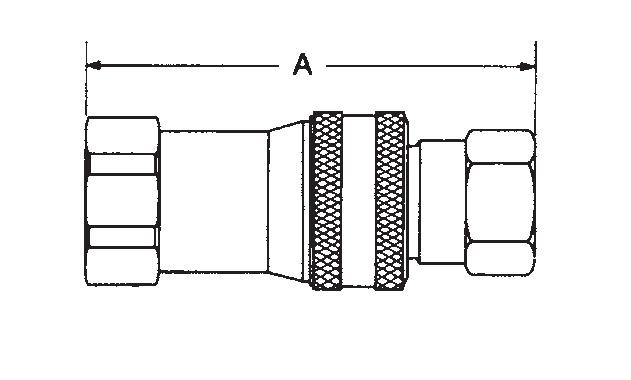
ISO 7241-1 B Interchange
Sockets (Female)
A=Overall Length, B=Maximum Diameter
To obtain connected length of coupling, add dimensions A (Fig. 1) and E (Fig. 3) together.
Sockets (Female)
A=Overall Length, B=Maximum Diameter
* ISO 7241-1 Series B does not include 1-¼ inch body size couplings; therefore, Series 10HK is not covered by this standard To obtain connected length of coupling, add dimensions A (Fig. 2) and E (Fig. 4) together.
9 PNEUMATIC SPECIAL APPLICATIONS DIAGNOSTIC AGRICULTURE REFRIGERANT FLUID TRANSFER AND HYDRAULIC EATON Quick Disconnect Couplings Master Catalog E-MEQD-CC001-E8 August 2017
Part Number HK1-8 SeriesBody SizeISO SizeThread Size (Female) Fig.Dimensions (in)(mm)NPTFBSPP SAE A (in) B (in) Across Flats (in) A (mm) B (mm) Across Flats (mm) 1H11 5 -27- - 1 1.910.980.56 48.524.914.2 1H4 5 - - -201 2.060.980.69 52.324.9 17.5 2H16 ¼ 6.3¼-18- - 1 2.26 1.14 0.75 57.429.019.1 2H16BS¼ 6.3- ¼-19- 1 2.31 1.14 0.75 58.729.019.1 2H6 ¼ 6.3- - -18 1 2.40 1.14 0.88 61.029.022.4 3H21 10 -18 - - 1 2.561.420.88 65.036.122.4 3H21BS 10 - -19 - 1 2.561.420.88 65.036.122.4 3H8 10 - - ¾-161 2.741.42 1.00 69.636.125.4 4HP26 ½ 12.5½-14- - 1 2.961.86 1.13 75.247.228.7 4HP26BS½ 12.5- ½-14- 1 2.961.86 1.13 75.247.228.7 4HP10 ½ 12.5- - -14 1 3.051.861.25 77.547.231.8 6HP31 ¾ 20 ¾-14- - 1 3.482.221.31 88.456.433.3 6HP31BS¾ 20 - ¾-14- 1 3.482.221.31 88.456.433.3 6HP12 ¾ 20 - - 1 -12 1 3.672.221.38 93.256.435.1 8HP36 1 25 1-11½- - 1 4.132.611.75104.966.344.5 8HP36BS1 25 - 1-11 - 1 4.132.611.75104.966.344.5 8HP16 1 25 - - 1 -12 1 4.132.611.88104.966.347.8
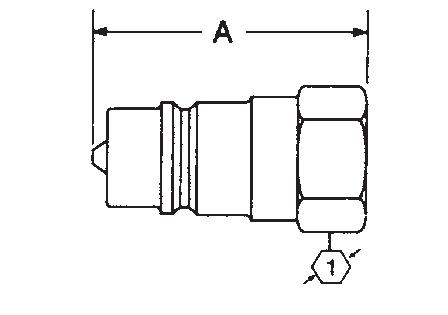
HK Series (Steel)
Part Number HK10/12/20 SeriesBody SizeISO SizeThread Size (Female) Fig.Dimensions (in) (mm)NPTFBSPP A (in)B (in)Hex (in)A (mm)B (mm)Hex (mm) 10H41* 1¼ - 1¼-11½- 2 4.512.732.38114.669.360.5 10H41BS* 1¼ - - 1¼-112 4.512.732.38114.669.360.5 12H41 1½ 40 1¼ -11½- 2 4.823.232.38122.482.060.5 12H41BS 1½ 40 - 1¼-112 4.823.232.38122.482.060.5 12H46 1½ 40 1½-11½- 2 4.823.232.38122.482.060.5 12H46BS 1½ 40 - 1½-112 4.823.232.38122.482.060.5 20H51 2½ 50 2-11½- 2 5.554.113.75141.0104.495.3 20H51BS 2½ 50 - 2-112 5.554.113.75141.0104.495.3 20H56 2½ 50 2½-8- 2 6.144.113.75156.0104.495.3 20H56BS 2½ 50 - 2½-112 6.144.113.75156.0104.495.3 20H61 2½ 50 3-8 - 2 7.00 4.114.00177.8104.4 101.6 20H61BS 2½ 50 - 3-112 7.00 4.114.00177.8104.4 101.6
Figure 1
Page 9
Figure 2
HK Series (Steel)
ISO 7241-1 B Interchange
Plugs (Male)
C=Overall Length, D=Maximum Diameter, E=Exposed Length when Connected To obtain connected length of coupling, add dimensions A (Fig. 1) and E (Fig. 3) together.
Plugs (Male)
C=Overall Length, D=Maximum Diameter, E=Exposed Length when Connected
* ISO 7241-1 Series B does not include 1-¼ inch body size couplings;therefore, ¼¼ 10HK is not covered by this standard To obtain connected length of coupling, add dimensions A (Fig. 2) and E (Fig. 4) together.
Dust Plugs and Dust Caps Accessories
Coupling Series Plug Dust Cap Part No.Socket Dust Plug Part No. MetalVinyl MetalVinyl
1HK PDC1HK* PPDC1HKSDC1HK* PSDC1HK
2HK PDC2HK* PPDC2HKSDC2HK* PSDC2HK
3HK PDC3HK* PPDC3HKSDC3HK* PSDC3HK
4HK PDC4HK** PPDC4HK(RD)*** SDC4HK** PSDC4HK(RD)***
6HK PDC6HK** PPDC6HK(RD)*** SDC6HK** PSDC6HK(RD)***
8HK PDC8HK** PPDC8HK(RD)*** SDC8HK** PSDC8HK(RD)***
12HK PDC12HK* SDC12HK*
20HK PDC20HK* SDC20HK*
*Brass **Aluminum ***Offered in red by adding RD to end of part number
Vinyl Dust Plug


Vinyl Dust Cap
Metal Dust Cap Metal Dust Plug


10 FLUID TRANSFER AND HYDRAULIC PNEUMATIC SPECIAL APPLICATIONS DIAGNOSTIC AGRICULTURE REFRIGERANT EATON Quick Disconnect Couplings Master Catalog E-MEQD-CC001-E8 August 2017
Part Number HK1-8 Series Body Size ISO Size Thread Size (Female) Fig.Dimensions (in)(mm)NPTFBSPP SAE C (in)D (in)E (in)Hex (in)C (mm)D (mm)E (mm)Hex (mm) 1K11 5 -27--31.260.650.440.5632.016.5 11.2 14.2 1K4 5-- -2031.410.790.590.6935.820.115.0 17.5 2K16 ¼ 6.3¼-18--31.520.870.560.7538.622.114.219.1 2K16BS¼ 6.3-¼-19-31.520.870.560.7538.622.114.219.1 2K6 ¼ 6.3-- -18 31.66 1.01 0.700.8842.225.7 17.8 22.4 3K21 10 -18 --3 1.761.01 0.610.8844.725.715.522.4 3K21BS 10 - -19 -3 1.761.01 0.610.8844.725.715.522.4 3K8 10 --¾-1631.94 1.15 0.79 1.00 49.329.220.125.4 4KP26 ½12.5½-14--32.031.300.76 1.13 51.633.019.328.7 4KP26BS½12.5-½-14-32.031.300.76 1.13 51.633.019.328.7 4KP10 ½12.5-- -14 32.111.370.84 1.19 53.634.821.330.2 6KP31 ¾20¾-14--32.361.520.711.3159.938.618.033.3 6KP31BS¾20-¾-14-32.361.520.711.3159.938.618.033.3 6KP12 ¾20--1 -12 32.541.590.891.3864.540.422.635.1 8KP36 1251-11½--32.851.880.971.6372.447.824.641.4 8KP36BS125- 1-11 -32.851.880.971.6372.447.824.641.4 8KP16 125 --1 -12 32.852.170.971.8872.455.124.647.8
Part Number HK10/12/20 Series Body Size ISO Size Thread Size (Female) Fig.Dimensions (in)(mm)NPTFBSPP C (in)D (in)E (in)Hex (in)C (mm)D (mm)E (mm)Hex (mm) 10K41* 1¼-1¼-11½-44.252.742.332.38108.069.659.260.5 10K41BS* 1¼--1¼-1144.252.742.332.38108.069.659.260.5 12K41 1½401¼-11½-44.762.742.672.38120.969.667.860.5 12K41BS 1½40-1¼-1144.762.742.672.38120.969.667.860.5 12K46 1½401½-11½-44.762.742.672.38120.969.667.860.5 12K46BS 1½40-1½-1144.762.742.672.38120.969.667.860.5 20K51 2½602-11½-45.494.332.973.75139.4110.075.495.3 20K51BS 2½60-2-1145.494.332.973.75139.4110.075.495.3 20K56 2½602½-8-46.084.333.563.75154.4110.090.495.3 20K56BS 2½60-2½-1146.084.333.563.75154.4110.090.495.3 20K61 2½603-8-46.944.624.424.00176.3 117.3 112.3 101.6 20K61BS 2½60-3-1146.944.624.424.00176.3 117.3 112.3 101.6
Figure 3
Page 10
Figure 4
HK Series (Brass) ISO 7241-1 B Interchange
Eaton’s HK brass is a general purpose industrial interchange coupling available in valved or non-valved designs, offered in brass for excelllent corrosion resistance in rugged applications where stainless steel is unacceptable. The HK Series features a ball latch mechanism with automatic self- sealing poppet valves.

Product Features
• Meets dimensional requirements to ISO standard 7241-1 Series B
• Brass construction with stainless steel springs for greater corrosion resistance and fluid compatibility
• Self-sealing poppet valves provide excellent high and low pressure sealing
• Standard seal material: Buna-N
• Seal options available in PTFE, Neoprene, FKM, EPDM, and Kalrez®
Physical Characteristics
*For questions related to vacuum please contact Eaton.
** No ISO Standard available for the 10HK
Applications & Markets
• Agriculture
• Hydraulic Tool
• General Industry
• Construction
• Fluid Transfer
• Chemical
• Oil and Gas
• Transportation
• Food and Beverage
• Trucks
• Nuclear
Flow Data
*For reference only, based on Eaton recommended temperatures. Contact Eaton technical support for further information on fluid compatibility.

11 PNEUMATIC SPECIAL APPLICATIONS DIAGNOSTIC AGRICULTURE REFRIGERANT FLUID TRANSFER AND HYDRAULIC EATON Quick Disconnect Couplings Master Catalog E-MEQD-CC001-E8 August 2017
Series Body SizeISO Size Nominal Flow Diameter Max. Operating Pressure Rated Flow Air InclusionFluid Loss (in) (mm) (mm) (bar) (psi) (lpm) (gpm) cc. max.cc. max. 1HK 5 4.4 207 3,000 3 0.8 0.6 0.5 2HK ¼ 6.3 5.9 186 2,700 12 3 1.2 0.9 3HK 10 7.8 152 2,200 23 6 2.9 2.1 4HK ½ 12.5 10 155 2,250 45 12 3.6 3.5 6HK ¾ 20 17 138 2,000 100 26 11.5 9.3 8HK 1 25 19.6 103 1,500 189 50 18.0 16.9 10HK 1¼** - 26.7 83 1,200 288 76 48.0 48.0 12HK 1½ 40 35.1 104 1,500 375 99 91.3 91.3 20HK 2½ 50 46 49 700 757 200 209.9 209.9
Seal Elastomer Data* Seal Elastomer Max. Operation Temperature Range Buna-N -40°C to +121°C/40°F to +250°F Neoprene -54°C to +100°C/-65°F to +212°F EPDM (Ethylene Propylene Rubber) -54°C to +149°C/-65°C to +300°F FKM -29°C to +204°C/-15°F to +400°F
Page 11
HK Series (Brass)
ISO 7241-1 B Interchange
Sockets (Female)
A=Overall Length, B=Maximum Diameter
To obtain connected length of coupling, add dimensions A (Fig. 1) and E (Fig. 3) together.
Sockets (Female)
A=Overall Length, B=Maximum Diameter
* ISO 7241-1 Series B does not include 1-¼ inch body size couplings; therefore, Series 10HK is not covered by this standard
To obtain connected length of coupling, add dimensions A (Fig. 2) and E (Fig. 4) together.

12 FLUID TRANSFER AND HYDRAULIC PNEUMATIC SPECIAL APPLICATIONS DIAGNOSTIC AGRICULTURE REFRIGERANT EATON Quick Disconnect Couplings Master Catalog E-MEQD-CC001-E8 August 2017
Part Number HK1-8 SeriesBody SizeISO SizeThread Size (Female) Fig.Dimensions (in) (mm)NPTFBSPP A (in) B (in) Across Flats (in) A (mm) B (mm) Across Flats (mm) B1H11 5 -27- 11.91 0.98 0.56 48.524.9 14.2 B2H16 ¼ 6.3¼-18- 12.26 1.14 0.75 57.429.0 19.1 B2H16BS¼ 6.3- ¼-1912.31 1.14 0.75 58.729.0 19.1 B3H21 10 -18 - 12.56 1.42 0.88 65.036.1 22.4 B3H21BS 10 - -19 12.56 1.42 0.88 65.036.1 22.4 B4HP26½ 12.5½-14- 12.96 1.86 1.13 75.247.2 28.7 B4HP26BS½ 12.5- ½-1412.96 1.86 1.13 75.247.2 28.7 B6HP31¾ 20 ¾-14- 13.48 2.22 1.31 88.456.4 33.3 B6HP31BS¾ 20 - ¾-1413.48 2.22 1.31 88.456.4 33.3 B8HP361 25 1-11½- 14.13 2.61 1.75 104.966.3 44.5 B8HP36BS1 25 - 1-11 14.13 2.61 1.75 104.966.3 44.5
Part Number HK10/12/20 SeriesBody SizeISO SizeThread Size (Female) Fig.Dimensions (in) (mm)NPTFBSPP A (in) B (in) Hex (in) A (mm) B (mm) Hex (mm) B10H41* 1¼ - 1¼-11½- 24.512.732.38114.6 69.360.5 B12H41 1½ 40 1¼-11½- 24.823.232.38122.4 82.060.5 B12H41BS 1½ 40 - 1¼-1124.823.232.38122.4 82.060.5 B12H46 1½ 40 1½-11- 24.823.232.38122.4 82.060.5 B12H46BS 1½ 40 - 1½-1124.823.232.38122.4 82.060.5 B20H51 2½ 50 2-11½- 25.554.11 3.75141.0 104.495.3 B20H51BS 2½ 50 - 2-11 25.554.11 3.75141.0 104.495.3 B20H56 2½ 50 2½-8- 26.14 4.11 3.75156.0104.495.3 B20H56BS 2½ 50 - 2½-1126.14 4.11 3.75156.0104.495.3 B20H61 2½ 50 3-8 - 2 7.00 4.11 4.00177.8 104.4 101.6 B20H61BS 2½ 50 - 3-11 2 7.00 4.11 4.00177.8 104.4 101.6
Figure 1
Page 12
Figure 2
ISO 7241-1 B Interchange
Plugs (Male)
Plugs (Male)
C=Overall Length, D=Maximum Diameter, E=Exposed Length when Connected
* ISO 7241-1 Series B does not include 1-¼ inch body size couplings; therefore, Series 10HK is not covered by this standard
To obtain connected length of coupling, add dimensions A (Fig. 2) and E (Fig. 4) together.
Dust Plugs and Dust Caps Accessories
Coupling Series Plug Dust Cap Part No. Socket Dust Plug Part No. MetalVinyl MetalVinyl
1HK PDC1HK* PPDC1HKSDC1HK* PSDC1HK
2HK PDC2HK* PPDC2HKSDC2HK* PSDC2HK
3HK PDC3HK* PPDC3HKSDC3HK* PSDC3HK
4HK PDC4HK** PPDC4HK(RD)*** SDC4HK** PSDC4HK(RD)***
6HK PDC6HK** PPDC6HK(RD)*** SDC6HK** PSDC6HK(RD)***
8HK PDC8HK** PPDC8HK(RD)*** SDC8HK** PSDC8HK(RD)***
12HK PDC12HK* SDC12HK*
20HK PDC20HK* SDC20HK*
*Brass **Aluminum ***Offered in red by adding RD to end of part number
Vinyl Dust Plug
Vinyl Dust Cap
Metal Dust Cap Metal Dust Plug
13 PNEUMATIC SPECIAL APPLICATIONS DIAGNOSTIC AGRICULTURE REFRIGERANT FLUID TRANSFER AND HYDRAULIC EATON Quick Disconnect Couplings Master Catalog E-MEQD-CC001-E8 August 2017
Part Number HK1-8 SeriesBody SizeISO Size Thread Size (Female) Fig.Dimensions (in)(mm)NPTFBSPP C (in) D (in) E (in) Hex (in) C (mm) D (mm) E (mm) Hex (mm) B1K11 5 -27- 31.260.650.440.5632.016.5 11.2 14.2 B2K16¼ 6.3¼-18- 31.520.870.560.7538.622.114.219.1 B2K16BS¼ 6.3- ¼-1931.520.870.560.7538.622.114.219.1 B3K21 10 -18 - 3 1.761.01 0.610.8844.725.715.522.4 B3K21BS 10 - -19 3 1.761.01 0.610.8844.725.715.522.4 B4KP26½ 12.5½-14- 32.031.300.76 1.13 51.633.019.328.7 B4KP26BS½ 12.5- ½-1432.031.300.76 1.13 51.633.019.328.7 B6KP31¾ 20¾-14- 32.361.520.711.3159.938.618.033.3 B6KP31BS¾ 20- ¾-1432.361.520.711.3159.938.618.033.3 B8KP361 251-11½- 32.851.880.971.6372.447.824.641.4 B8KP36BS1 25- 1-11 32.851.880.971.6372.447.824.641.4 C=Overall
Length, D=Maximum Diameter, E=Exposed Length when Connected To obtain connected length of coupling, add dimensions A (Fig. 1) and E (Fig. 3) together.
Part Number HK10/12/20 SeriesBody SizeISO Size Thread Size (Female) Fig.Dimensions (in)(mm)NPTFBSPP C (in) D (in) E (in) Hex (in) C (mm) D (mm) E (mm) Hex (mm) B10K41* 1¼- 1¼-11½- 44.252.742.332.38108.069.659.260.5 B12K41 1½401¼-11½- 44.762.742.672.38120.969.667.860.5 B12K41BS 1½40- 1¼-1144.762.742.672.38120.969.667.860.5 B12K46 1½401½-11½- 44.762.742.672.38120.969.667.860.5 B12K46BS 1½40- 1½-1144.762.742.672.38120.969.667.860.5 B20K51 2½502-11½- 45.494.332.973.75139.4110.075.495.3 B20K51BS 2½50- 2-1145.494.332.973.75139.4110.075.495.3 B20K56 2½502½-8- 46.084.333.563.75154.4110.090.495.3 B20K56BS 2½50- 2½-1146.084.333.563.75154.4110.090.495.3 B20K61 2½503-8- 46.944.624.424.00176.3 117.3 112.3 101.6 B20K61BS 2½50- 3-1146.944.624.424.00176.3 117.3 112.3 101.6
HK Series (Brass)
Figure 3
Page 13
Figure 4
HK Series Series (Stainless Steel)
ISO 7241-1 B Interchange
Eaton’s HK Series stainless steel is a general purpose industrial interchange coupling available in valved or non-valved designs, offered in 303/316 grades of stainless steel for excellent corrosion resistance in rugged applications. The HK Series features a ball latch mechanism with automatic self-sealing poppet valves.
Product Features
• Meets dimensional requirements to ISO standard 7241-1 Series B
• 303/316 Stainless steel construction for greater corrosion resistance and fluid compatibility
• Self-sealing poppet valves provide excellent high and low pressure sealing

• Standard body material: 303 or 316 Stainless Steel
• Standard seal material: Buna-N
• Seal options available in PTFE, Neoprene, FKM, EPDM, and Kalrez®
Physical Characteristics
* For questions related to vacuum please contact Eaton.
** No ISO Standard available for the 10HK
Applications & Markets
• Agriculture
• Hydraulic Tool
• General Industry
• Construction
• Fluid Transfer
• Transportation
• Military
• Law Enforcement/Rescue
• Chemical
• Oil and Gas
• Consumer Products
• HVAC
• Food and Beverage
• Trucks
• Aerospace
• Medical
Flow
* For reference only, based on Eaton recommended temperatures. Contact Eaton technical support for further information on fluid compatibility.

14 FLUID TRANSFER AND HYDRAULIC PNEUMATIC SPECIAL APPLICATIONS DIAGNOSTIC AGRICULTURE REFRIGERANT EATON Quick Disconnect Couplings Master Catalog E-MEQD-CC001-E8 August 2017
Series Body SizeISO Size Nominal Flow Diameter Max. Operating Pressure Rated Flow Air InclusionFluid Loss (in) (mm) (mm) (bar) (psi) (lpm) (gpm) cc. max.cc. max. 1HK 5 4.4 344 5,000 3 0.8 0.6 0.5 2HK ¼ 6.3 5.9 255 3,700 12 3 1.2 0.9 3HK 10 7.8 255 3,700 23 6 2.9 2.1 4HK ½ 12.5 10 293 4,250 45 12 3.6 3.5 6HK ¾ 20 17 242 3,500 100 26 11.5 9.3 8HK 1 25 19.6 207 3,000 189 50 18.0 16.9 10HK 1¼** - 26.7 118 1,700 288 76 48.0 48.0 12HK 1½ 40 35.1 152 2,200 375 99 91.3 91.3 20HK 2½ 50 46 104 1,500 757 200 209.9 209.9
Seal Elastomer Data* Seal Elastomer Max. Operation Temperature Range Buna-N -40°C to +121°C/40°F to +250°F Neoprene -54°C to +100°C/-65°F to +212°F EPDM (Ethylene Propylene Rubber) -54°C to +149°C/-65°C to +300°F FKM -29°C to +204°C/-15°F to +400°F
Data Page 14
HK Series Series (Stainless Steel)
ISO 7241-1 B Interchange
Sockets (Female)
A=Overall Length, B=Maximum Diameter
* ISO 7241-1 Series B does not include 1-¼ inch body size couplings;therefore, Series 10HK is not covered by this standard. To obtain connected length of coupling, add dimensions A (Fig. 2) and E (Fig. 4) together.
15 PNEUMATIC SPECIAL APPLICATIONS DIAGNOSTIC AGRICULTURE REFRIGERANT FLUID TRANSFER AND HYDRAULIC EATON Quick Disconnect Couplings Master Catalog E-MEQD-CC001-E8 August 2017
Part Number HK1-8 Series 303 Stainless Steel 316 Stainless Steel Body Size ISO Size Thread Size (Female) Fig.Dimensions (in)(in)NPTFBSPP SAE A (in) B (in) Across Flats (in) A (mm) B (mm) Across Flats (mm) LL1H11 ML1H11 5 -27- - 11.910.980.5648.524.914.2 LL1H4 - 5- - -2012.060.980.6952.324.9 17.5 LL2H16 ML2H16¼6.3¼-18- - 12.26 1.14 0.7557.429.019.1 LL2H16BS ML2H16BS¼6.3- ¼-19- 12.31 1.14 0.7558.729.019.1 LL2H6 - ¼6.3- - -18 12.40 1.14 0.8861.029.022.4 LL3H21 ML3H21 10 -18 - - 12.561.420.8865.036.122.4 LL3H21BS ML3H21BS 10 - -19 - 12.561.420.8865.036.122.4 LL3H8 - 10 - - ¾-1612.741.42 1.00 69.636.125.4 LL4HP26 ML4HP26½12.5½-14- - 12.961.86 1.13 75.247.228.7 LL4HP26BS ML4HP26BS½12.5- ½-14- 12.961.86 1.13 75.247.228.7 LL4HP10 - ½12.5- - -14 13.051.861.25 77.547.231.8 LL6HP31 ML6HP31¾20¾-14- - 13.482.221.3188.456.433.3 LL6HP31BS ML6HP31BS¾20- ¾-14- 13.482.221.3188.456.433.3 LL6HP12 - ¾20- - -12 13.672.221.3893.256.435.1 LL8HP36 ML8HP361251-11½- - 14.132.611.75104.966.344.5 LL8HP36BS ML8HP36BS125- 1-11 - 14.132.611.75104.966.344.5 LL8HP16 - 125- - 11 -12 14.132.611.88104.966.347.8
Length, B=Maximum Diameter
obtain connected length of coupling, add dimensions A (Fig. 1) and E (Fig. 3) together. Sockets (Female) Part Number HK10/12/20 Series 303 Stainless SteelBody SizeISO SizeThread Size (Female) Fig.Dimensions (in)(mm)NPTFBSPP A (in) B (in) Hex (in) A (mm) B (mm) Hex (mm) LL10H41* 1¼ - 1¼-11½- 24.51 2.73 2.38 114.6 69.3 60.5 LL10H41BS* 1¼ - - 1¼-1124.51 2.73 2.38 114.6 69.3 60.5 LL12H41 1½ 40 1¼-11½- 24.82 3.23 2.38 122.4 82.0 60.5 LL12H41BS 1½ 40 - 1¼-1124.82 3.23 2.38 122.4 82.0 60.5 LL12H46 1½ 40 1½-11½- 24.82 3.23 2.38 122.4 82.0 60.5 LL12H46BS 1½ 40 - 1½-1124.82 3.23 2.38 122.4 82.0 60.5 LL20H51 2½ 50 2-11½- 25.55 4.11 3.75 141.0 104.4 95.3 LL20H51BS 2½ 50 - 2-1125.55 4.11 3.75 141.0 104.4 95.3 LL20H56 2½ 50 2½-8- 26.14 4.11 3.75 156.0104.4 95.3 LL20H56BS 2½ 50 - 2½-1126.14 4.11 3.75 156.0104.4 95.3 LL20H61 2½ 50 3-8 - 2 7.00 4.11 4.00 177.8 104.4 101.6 LL20H61BS 2½ 50 - 3-112 7.00 4.11 4.00 177.8 104.4 101.6
A=Overall
To
Figure 1
Page 15
Figure 2
HK Series (Stainless Steel)
ISO 7241-1 B Interchange
Plugs (Male)
C=Overall Length, D=Maximum Diameter, E=Exposed Length when Connected
* ISO 7241-1 Series B does not include 1-¼ inch body size couplings; therefore, Series 10HK is not covered by this standard. To obtain connected length of coupling, add dimensions A (Fig. 2) and E (Fig. 4) together.
Dust Plugs and Dust Caps Accessories
Coupling Series Plug Dust Cap Part No.Socket Dust Plug Part No. MetalVinyl MetalVinyl
1HK PDC1HK* PPDC1HKSDC1HK* PSDC1HK
2HK PDC2HK* PPDC2HKSDC2HK* PSDC2HK
3HK PDC3HK* PPDC3HKSDC3HK* PSDC3HK
4HK PDC4HK** PPDC4HK(RD)*** SDC4HK** PSDC4HK(RD)***
6HK PDC6HK** PPDC6HK(RD)*** SDC6HK** PSDC6HK(RD)***
8HK PDC8HK** PPDC8HK(RD)*** SDC8HK** PSDC8HK(RD)***
12HK PDC12HK* SDC12HK* 20HK PDC20HK* SDC20HK*
*Brass **Aluminum ***Offered in red by adding RD to end of part number
Vinyl Dust Plug
Vinyl Dust Cap
Metal Dust Cap Metal Dust Plug
16 FLUID TRANSFER AND HYDRAULIC PNEUMATIC SPECIAL APPLICATIONS DIAGNOSTIC AGRICULTURE REFRIGERANT EATON Quick Disconnect Couplings Master Catalog E-MEQD-CC001-E8 August 2017
Part Number HK1-8 Series 303 Stainless Steel 316 Stainless Steel Body Size ISO Size Thread Size (Female) Fig.Dimensions (in)(mm)NPTFBSPP SAE C (in) D (in) E (in) Hex (in) C (mm) D (mm) E (mm) Hex (mm) LL1K11 ML1K11 5 -27--31.260.650.440.5632.016.5 11.2 14.2 LL1K4 - 5-- -2031.410.790.590.6935.820.115.0 17.5 LL2K16 ML2K16 ¼6.3¼-18--31.520.870.560.7538.622.114.219.1 LL2K16BS ML2K16BS ¼6.3-¼-19-31.520.870.560.7538.622.114.219.1 LL2K6 - ¼6.3-- -18 31.66 1.01 0.700.8842.225.7 17.8 22.4 LL3K21 ML3K21 10 -18 --3 1.761.01 0.610.8844.725.715.522.4 LL3K21BS ML3K21BS 10 - -19 -3 1.761.01 0.610.8844.725.715.522.4 LL3K8 - 10 --¾-1631.94 1.15 0.79 1.00 49.329.220.125.4 LL4KP26 ML4KP26 ½12.5½-14--32.031.300.76 1.13 51.633.019.328.7 LL4KP26BS ML4KP26BS ½12.5-½-14-32.031.300.76 1.13 51.633.019.328.7 LL4KP10 - ½12.5-- -14 32.111.370.84 1.19 53.634.821.330.2 LL6KP31 ML6KP31 ¾20¾-14--32.361.520.711.3159.938.618.033.3 LL6KP31BS ML6KP31BS ¾20-¾-14-32.361.520.711.3159.938.618.033.3 LL6KP12 - ¾20--1 -12 32.541.590.891.3864.540.422.635.1 LL8KP36 ML8KP36 1251-11½--32.851.880.971.6372.447.824.641.4 LL8KP36BS ML8KP36BS 125- 1-11 -32.851.880.971.6372.447.824.641.4 LL8KP16 - 125--1 -12 32.852.170.971.8872.455.124.647.8
(Male) Part Number HK10/12/20 Series 303 Stainless Steel Body Size ISO Size Thread Size (Female) Fig.Dimensions (in)(mm)NPTFBSPP C (in) D (in) E (in) Hex (in) C (mm) D (mm) E (mm) Hex (mm) LL10K41* 1¼- 1¼-11½- 4 4.252.742.332.38108.069.659.260.5 LL10K41BS* 1¼- - 1¼-114 4.252.742.332.38108.069.659.260.5 LL12K41 1½401¼-11½- 4 4.762.742.672.38120.969.667.860.5 LL12K41BS 1½40- 1¼-114 4.762.742.672.38120.969.667.860.5 LL12K46 1½401½-11½- 4 4.762.742.672.38120.969.667.860.5 LL12K46BS 1½40- 1½-114 4.762.742.672.38120.969.667.860.5 LL20K51 2½502-11½- 4 5.494.332.973.75139.4110.075.495.3 LL20K51BS 2½50- 2-114 5.494.332.973.75139.4110.075.495.3 LL20K56 2½502½-8- 4 6.084.333.563.75154.4110.090.495.3 LL20K56BS 2½50- 2½-114 6.084.333.563.75154.4110.090.495.3 LL20K61 2½503-8- 4 6.944.624.424.00176.3 117.3 112.3 101.6 LL20K61BS 2½50- 3-114 6.944.624.424.00176.3 117.3 112.3 101.6
C=Overall Length, D=Maximum Diameter, E=Exposed Length when Connected To obtain connected length of coupling, add dimensions A (Fig. 1) and E (Fig. 3) together. Plugs
Figure 3
Page 16
Figure 4
HKFR Series ISO 7241-1 BOP
Product Features
• BOP designation and red color is marked on the Socket/Female and Plug/Male halves
• Sleeve lock is standard
Physical Characteristics
Eaton’s HKFR Series is a quick disconnect hydraulic coupling for hazardous Blow Out Preventer (BOP) service in the Oil and Gas Industry. The HKFR Series meets or exceeds the ISO 7241-1 B standard.

• Lloyd’s Register Certification
• Meets or exceeds ISO 7241-1 Series B standard
• Utilizes HK Series dust caps and dust plugs
• Standard body material: 316 stainless steel, zinc trivalent plated steel
• Standard seal material: Buna-N
Applications & Markets
Lloyd's Register Certification
All of the above items carry a Llyod's Registry Certificate for fire conditions stated in API 16D and EUB Directive 36. These parts meet the requirements that state couplings shall be capable of maintaining pressure when exposed to a 700˚C (1,300˚F) temperature for a five-minute period. Testing for this certification was conducted at the following pressures in the connected condition:
Female End Connections
17 PNEUMATIC SPECIAL APPLICATIONS DIAGNOSTIC AGRICULTURE REFRIGERANT FLUID TRANSFER AND HYDRAULIC EATON Quick Disconnect Couplings Master Catalog E-MEQD-CC001-E8 August 2017
Max. Operating Pressure Series Body Size Connected Min. Burst Pressure Rated Flow Fluid Loss (in) (bar) (psi) (bar) (psi) (lpm) (gpm) cc. max 4HKFR 1/2 482 7,000 1,931 28,000 28 7.5 3.5 6HKFR 3/4 344 5,000 1,251 18,150 66 17.5 9.3 8HKFR 1 344 5,000 1,379 20,000 95 25 16.9 ML8HKFR 1 344 5,000 1,379 20,000 95 25 16.9
Part Coupling Body Dimensions Number Type Size Thread Fig. A B Across Flats A B Across Flats (in) (in) (in) (mm) (mm) (mm) 4HFR26 Socket/Female 1/2 1/2-14 NPTF 1 2.96 1.86 1.13 75.2 47.2 28.7 6HFR31 Socket/Female 3/4 3/4-14 NPTF 1 3.48 2.22 1.31 88.4 56.4 33.3 8HFR36 Socket/Female 1 1-1 1/2 NPTF 1 4.13 2.61 1.75 104.9 66.3 44.5 ML8HFR36* Socket/Female 1 1-1 1/2 NPTF 1 4.13 2.61 1.75 104.9 66.3 44.5 *S tainless Steel Plugs/Males Part Coupling Body Dimensions Number Type Size Thread Fig. C D E Hex C D E Hex (in) (in) (in) (mm) (mm) (mm) 4KFR26 Plug/Male 1/2 1/2-14 NPTF 2 2.03 1.3 0.76 1.13 51.6 33.0 19.3 28.7 6KFR31 Plug/Male 3/4 3/4-14 NPTF 2 2.36 1.52 0.71 1.31 59.9 38.6 18.0 33.3 8KFR36 Plug/Male 1 1-11 1/2 NPTF 2 2.85 1.88 0.97 1.63 72.4 47.8 24.6 41.4 ML8KFR36* Plug/Male 1 1-11 1/2 NPTF 2 2.85 1.88 0.97 1.63 72.4 47.8 24.6 41.4
* Stainless Steel
4HFR26/4KFR26: 3,000 PSI/206 BAR 6HFR31/6KFR31: 3,000 PSI/206 BAR 8HFR36/8KFR36: 4,000 PSI/275 BAR ML8HFR36/ML8KFR36: 4,000 PSI/275 BAR
gas
• Oil and
Figure 1
Page 17
Figure 2
ISO 7241-1 A Interchange
Eaton’s 5600 Series features a rugged ball latch mechanism with self-sealing poppet valves in a wide array of port configurations and multiple valved and non-valved configurations.
Product Features
• Meets dimensional requirements to ISO standard 7241-1Series A
• Self-sealing poppet valve provides excellent high and low pressure sealing

• Streamlined valving provides minimum pressure drop
• Standard seal materials: Buna-N, EPDM and FKM
• Standard body material: High resistance carbon steel with zinc trivalent plating (Brass poppet guide in –04 size)
Physical Characteristics
Applications & Markets
• Hydraulic fluid transfer
• Agricultural equipment
• Construction equipment
• Dump, snow plow and maintenance vehicles
• In -plant
18 FLUID TRANSFER AND HYDRAULIC PNEUMATIC SPECIAL APPLICATIONS DIAGNOSTIC AGRICULTURE REFRIGERANT EATON Quick Disconnect Couplings Master Catalog E-MEQD-CC001-E8 August 2017 Flow Data Pressure Drop Versus Flow Graph Gallons Per Minute Flow Test Fluid: MIL-H-5606 Oil at 100°F 4 6 8 10 20 30 40 50 70 100 200 300 0.05 0.1 0.2 0.3 0.5 1 2 3 bar lpm 1.06 2.64 5.28 13.2 26.4 52.8 79.2 0.725 1.45 2.9 4.35 7.25 14.5 29 43.5 gpm psi Pressure Drop, bar
Body Max. Operating Min. Burst Pressure Vacuum Rated Air Fluid Size Pressure Connected Connected Only Flow Inclusion Loss (in) (bar) (psi) (bar) (psi) (in./Hg) (lpm) (gpm) cc. max. cc.max. 1/4 350 5,00 0 1,050 15,0 00 28 4 1 0.50 0.50 3/8 280 4,00 0 840 12,0 00 28 23 6 1.5 1.3 5/8 280 4,00 0 840 12,0 00 28 45 12 2.8 2.8 3/4 280 4,00 0 840 12,0 00 28 106 28 10.0 8.2 1 280 4,00 0 840 12,0 00 28 189 50 14.2 14.2
manufacturing 1/4 3/8 5/8 3/4 1
5600 Series
Page 18
ISO 7241-1 A Interchange

19 PNEUMATIC SPECIAL APPLICATIONS DIAGNOSTIC AGRICULTURE REFRIGERANT FLUID TRANSFER AND HYDRAULIC EATON Quick Disconnect Couplings Master Catalog E-MEQD-CC001-E8 August 2017 Dimensions (Female NPT, Valved) Part Number Coupling Body Port Dimensions Buna-N FKM EPDM Type Size Size Thread Type Fig. A B Hex 1 mm (in) mm (in) mm (in) 5602-2-4S FD56-1062-02-04 5644-2-4S Plug/Male 1/4 1/8 1/8-27 Female NPT 1 31.5 (1.24) - - 14.2 (.56) 5601-2-4S FD56-1064-02-04 5643-2-4S Socket/Female 1/4 1/8 1/8-27 Female NPT 2 46 (1.81) 27.4 (1.08) 22.4 (.88) 5600-2-4S FD56-1065-02-04 5642-2-4S Complete 1/4 1/8 1/8-27 Female NPT 3 61.5 (2.42) - - -5602-4-4S FD56-1062-04-04 5644-4-4S Plug/Male 1/4 1/4 1/4-18 Female NPT 1 33.3 (1.31) - - 19.1 (.75) 5601-4-4S FD56-1064-04-04 5643-4-4S Socket/Female 1/4 1/4 1/4-18 Female NPT 2 46 (1.81) 27.4 (1.08) 22.4 (.88) 5600-4-4S FD56-1065-04-04 5642-4-4S Complete 1/4 1/4 1/4-18 Female NPT 3 63.2 (2.49) - - -5602-6-6S FD56-1062-06-06 5644-6-6S Plug/Male 3/8 3/8 3/8-18 Female NPT 1 37.3 (1.47) - - 22.4 (.88) 5601-6-6S FD56-1064-06-06 5643-6-6S Socket/Female 3/8 3/8 3/8-18 Female NPT 2 54.6 (2.15) 31.2 (1.23) 25.4 (1.00) 5600-6-6S FD56-1065-06-06 5642-6-6S Complete 3/8 3/8 3/8-18 Female NPT 3 71.1 (2.80) - - -5602-8-10S FD56-1062-08-10 5644-8-10S Plug/Male 5/8 1/2 1/2-14 Female NPT 1 51.3 (2.02) - - 26.9 (1.06) 5601-8-10S FD56-1064-08-10 5643-8-10S Socket/Female 5/8 1/2 1/2-14 Female NPT 2 66.3 (2.61) 38.1 (1.50) 30.2 (1.19) 5600-8-10S FD56-1065-08-10 5642-8-10S Complete 5/8 1/2 1/2-14 Female NPT 3 96 (3.78) - - -5602-12-10S FD56-1062-12-10 5644-12-10S Plug/Male 5/8 3/4 3/4-14 Female NPT 1 54.9 (2.16) - - 35.1 (1.38) 5601-12-10S FD56-1064-12-10 5643-12-10S Socket/Female 5/8 3/4 3/4-14 Female NPT 2 66.3 (2.61) 38.1 (1.50) 33.3 (1.31) 5600-12-10S FD56-1065-12-10 5642-12-10S Complete 5/8 3/4 3/4-14 Female NPT 3 103.1 (4.06) - - -5602-12-12S FD56-1062-12-12 5644-12-12S Plug/Male 3/4 3/4 3/4-14 Female NPT 1 64.8 (2.55) - - 35.1 (1.38) 5601-12-12S FD56-1064-12-12 5643-12-12S Socket/Female 3/4 3/4 3/4-14 Female NPT 2 82.6 (3.25) 46 (1.81) 38.1 (1.50) 5600-12-12S FD56-1065-12-12 5642-12-12S Complete 3/4 3/4 3/4-14 Female NPT 3 115.8 (4.56) - - -5602-16-16S FD56-1062-16-16 5644-16-16S Plug/Male 1 1 1-11 1/2 Female NPT 1 78.7 (3.10) - - 41.1 (1.62) 5601-16-16S FD56-1064-16-16 5643-16-16S Socket/Female 1 1 1-11 1/2 Female NPT 2 97 (3.82) 53.3 (2.10) 42.9 (1.69) 5600-16-16S FD56-1065-16-16 5642-16-16S Complete 1 1 1-11 1/2 Female NPT 3 123.4 (4.86) - - -Dimensions (Female NPT, Valved with Sleeve Lock) Part Number Coupling Body Port Dimensions Buna-N Type Size Size Thread Type Fig. A B Hex 1 mm (in) mm (in) mm (in) FD56-1239-08-10 Socket/Female 5/8 1/2 1/2-14 Female NPT 2 66.3 (2.61) 38.1 (1.50) 30.2 (1.19) FD56-1239-12-12 Socket/Female 3/4 3/4 3/4-14 Female NPT 2 82.6 (3.25) 46.7 (1.84) 38.1 (1.50) FD56-1239-16-16 Socket/Female 1 1 1-11 1/2 Female NPT 2 97.0 (3.82) 54.1 (2.13) 42.9 (1.69)
Figure 2
Figure 1
Figure 3
5600 Series
Page 19
5600 Series
ISO
7241-1 A Interchange
Dimensions (Female NPT, Non-Valved)
Note: Will not operate with valved coupling halves; no valve actuator. *Male halves contain no seals.
Dimensions (Female NPT, Pusher-Style Valving)

Note: Incorporates a pusher device to open mating valved coupling halves.

Dimensions (Plug/Male Half, Female BSP/Valved)

20 FLUID TRANSFER AND HYDRAULIC PNEUMATIC SPECIAL APPLICATIONS DIAGNOSTIC AGRICULTURE REFRIGERANT EATON Quick Disconnect Couplings Master Catalog E-MEQD-CC001-E8 August 2017
Part Number Coupling Body Port Dimensions Buna-N FKM EPDM Type Size Size Thread Type Fig. A B Hex 1 mm (in) mm (in) mm (in) FD56-1037-04-04 FD56-1037-04-04 FD56-1037-04-04 Plug/Male* 1/4 1/4 1/4-18 Female NPT 1 31.5 (1.24) - - 19.1 (.75) FD56-1225-04-04 FD56-1207-04-04 FD56-1204-04-04 Socket/Female 1/4 1/4 1/4-18 Female NPT 2 46.0 (1.81) 27.4 (1.08) 22.4 (.88) FD56-1226-04-04 FD56-1208-04-04 FD56-1205-04-04 Complete* 1/4 1/4 1/4-18 Female NPT 3 63.2 (2.49) - - -FD56-1037-06-06 FD56-1037-06-06 FD56-1037-06-06 Plug/Male* 3/8 3/8 3/8-18 Female NPT 1 35.6 (1.40) - - 22.4 (.88) FD56-1225-06-06 FD56-1207-06-06 FD56-1204-06-06 Socket/Female 3/8 3/8 3/8-18 Female NPT 2 54.6 (2.15) 31.2 (1.23) 25.4 (1.00) FD56-1226-06-06 FD56-1208-06-06 FD56-1205-06-06 Complete* 3/8 3/8 3/8-18 Female NPT 3 71.1 (2.80) - - -FD56-1037-08-10 FD56-1037-08-10 FD56-1037-08-10 Plug/Male* 5/8 1/2 1/2-14 Female NPT 1 48 (1.89) - - 26.9 (1.06) FD56-1225-08-10 FD56-1207-08-10 FD56-1204-08-10 Socket/Female 5/8 1/2 1/2-14 Female NPT 2 66.3 (2.61) 38.1 (1.50) 30.2 (1.19) FD56-1226-08-10 FD56-1208-08-10 FD56-1205-08-10 Complete* 5/8 1/2 1/2-14 Female NPT 3 96 (3.78) - - -FD56-1037-12-12 FD56-1037-12-12 FD56-1037-12-12 Plug/Male* 3/4 3/4 3/4-14 Female NPT 1 57.9 (2.28) - - -FD56-1225-12-12 FD56-1207-12-12 FD56-1204-12-12 Socket/Female 3/4 3/4 3/4-14 Female NPT 2 82.6 (3.25) 46.0 (1.81) 38.1 (1.50) FD56-1226-12-12 FD56-1208-12-12 FD56-1205-12-12 Complete* 3/4 3/4 3/4-14 Female NPT 3 113.3 (4.46) - - -FD56-1037-16-16 FD56-1037-16-16 FD56-1037-16-16 Plug/Male* 1 1 1-11 1/2 Female NPT 1 70.4 (2.77) - - 41.1 (1.62) FD56-1225-16-16 FD56-1207-16-16 FD56-1204-16-16 Socket/Female 1 1 1-11 1/2 Female NPT 2 97 (3.82) 53.3 (2.10) 42.9 (1.69) FD56-1226-16-16 FD56-1208-16-16 FD56-1205-16-16 Complete* 1 1 1-11 1/2 Female NPT 3 140.7 (5.54) - - - -
Part Number Coupling Body Port Dimensions Buna-N FKM EPDM Type Size Size Thread Type Fig. A B Hex 1 mm (in) mm (in) mm (in) FD56-1125-04-04 FD56-1125-04-04 FD56-1125-04-04 Plug/Male 1/4 1/4 1/4-18 Female NPT 1 31.5 (1.24) - - 19 (.75) FD56-1123-04-04 FD56-1201-04-04 FD56-1196-04-04 Socket/Female 1/4 1/4 1/4-18 Female NPT 2 46 (1.81) 27.4 (1.08) 22.4 (.88) FD56-1125-06-06 FD56-1125-06-06 FD56-1125-06-06 Plug/Male 3/8 3/8 3/8-18 Female NPT 1 35.6 (1.40) - - 22.4 (.88) FD56-1123-06-06 FD56-1201-06-06 FD56-1196-06-06 Socket/Female 3/8 3/8 3/8-18 Female NPT 2 54.6 (2.15) 31.2 (1.23) 25.4 (1.00) FD56-1125-08-10 FD56-1125-08-10 FD56-1125-08-10 Plug/Male 5/8 1/2 1/2-14 Female NPT 1 48 (1.89) - - 26.9 (1.06) FD56-1123-08-10 FD56-1201-08-10 FD56-1196-08-10 Socket/Female 5/8 1/2 1/2-14 Female NPT 2 66.3 (2.61) 38.1 (1.50) 30.2 (1.19) FD56-1125-12-12 FD56-1125-12-12 FD56-1125-12-12 Plug/Male 3/4 3/4 3/4-14 Female NPT 1 57.9 (2.28) - - 35.1 (1.38) FD56-1123-12-12 FD56-1201-12-12 FD56-1196-12-12 Socket/Female 3/4 3/4 3/4-14 Female NPT 2 82.6 (3.25) 46 (1.81) 38.1 (1.50) FD56-1125-16-16 FD56-1125-16-16 FD56-1125-16-16 Plug/Male 1 1 1-11 1/2 Female NPT 1 70.4 (2.77) - - 41.1 (1.62) FD56-1123-16-16 FD56-1201-16-16 FD56-1196-16-16 Socket/Female 1 1 1-11 1/2 Female NPT 2 97 (3.82) 53.3 (2.10) 42.9 (1.69)
Part Number Body Dimensions Buna-N Size Thread Fig. A B Hex 1 (in) mm (in) mm (in) mm G5623-4-4 1/4 G 1/4 1 (1.34) 34 - - (0.75) 19.0 G5623-6-6 3/8 G 3/8 1 (1.50) 38 - - (0.91) 23.0 G5623-8-10 5/8 G 1/2 1 (1.73) 44 - - (1.06) 27.0 G5623-12-12 3/4 G 3/4 1 (2.17) 55 - - (1.38) 35.0 G5623-16-16 1 G 1 1 (2.52) 64 - - (1.61) 41.0
Figure 2
Figure 1
Page 20
Figure 3
5600 Series ISO 7241-1 A Interchange
Dimensions (Socket/Female Half, Female BSP/Valved)
(Female NPT, Connect Under Pressure Style)
Dimensions (Female, SAE O-Ring Valved)

Dimensions (Female SAE O-Ring, Valved with Sleeve Lock)

21 PNEUMATIC SPECIAL APPLICATIONS DIAGNOSTIC AGRICULTURE REFRIGERANT FLUID TRANSFER AND HYDRAULIC EATON Quick Disconnect Couplings Master Catalog E-MEQD-CC001-E8 August 2017
Part Number Body Dimensions Buna-N Size Thread Fig. A B Hex 1 (in) mm (in) mm (in) mm G5622-4-4 1/4 G 1/4 2 (1.89) 48 (1.04) 26.3 (0.87) 22.0 G5622-6-6 3/8 G 3/8 2 (2.20) 56 (1.18) 30 (1.06) 27.0 G5622-8-10 5/8 G 1/2 2 (2.60) 66 (1.51) 38.3 (1.06) 27.0 G5622-12-12 3/4 G 3/4 2 (3.25) 82.5 (1.89) 48 (1.57) 40.0 G5622-16-16 1 G 1 2 (3.86) 98 (2.09) 53 (1.97) 50.0
Part Number Coupling Body Port Dimensions Buna-N FKM EPDM Type Size Size Thread Type Fig. A B Hex 1 mm (in) mm (in) mm (in) 5602-8-10S FD56-1062-08-10 5644-8-10S Plug/Male 5/8 1/2 1/2-14 Female NPT Valved 1 51.3 (2.02) - - 26.9 (1.06) 5651-8-10S FD56-1070-08-10 565007-8-10S Socket/Female 5/8 1/2 1/2-14 Female NPT 4 73.2 (2.88) 38.1 (1.50) 26.9 (1.06) 5650-8-10S FD56-1071-08-10 565006-8-10S Complete 5/8 1/2 1/2-14 Female NPT 5 98.8 (3.89) - - -5602-12-10S FD56-1062-12-10 5644-12-10S Plug/Male 5/8 3/4 3/4-14 Female NPT Valved 1 54.9 (2.16) - - 35.1 (1.38) 5651-12-10S FD56-1070-12-10 565007-12-10S Socket/Female 5/8 3/4 3/4-14 Female NPT 4 83.8 (3.30) 38.1 (1.50) 31.8 (1.25) 5650-12-10S FD56-1071-12-10 565006-12-10S Complete 5/8 3/4 3/4-14 Female NPT 5 113 (4.45) - - - -
Dimensions
Part Number Coupling Body Port Dimensions Buna-N FKM EPDM Type Size Size Thread Type Fig. A B Hex 1 mm (in) mm (in) mm (in) 5610-4-4S FD56-1072-04-04 560078-4-4S Plug/Male 1/4 7/16 7/16-20 Female SAE O-Ring 1 32.5 (1.28) - - 15.7 (.62) 5608-4-4S FD56-1074-04-04 FD56-1012-04-04S Socket/Female 1/4 7/16 7/16-20 Female SAE O-Ring 2 46 (1.81) 27.4 (1.08) 22.4 (.88) 5606-4-4S FD56-1075-04-04 FD56-1009-04-04S Complete 1/4 7/16 7/16-20 Female SAE O-Ring 3 64.3 (2.53) - - -5610-6-6S FD56-1072-06-06 560078-6-6S Plug/Male 3/8 9/16 9/16-18 Female SAE O-Ring 1 38.1 (1.50) - - 22.4 (.88) 5608-6-6S FD56-1074-06-06 FD56-1012-06-06S Socket/Female 3/8 9/16 9/16-18 Female SAE O-Ring 2 54.6 (2.15) 31.2 (1.23) 25.4 (1.00) 5606-6-6S FD56-1075-06-06 FD56-1009-06-06S Complete 3/8 9/16 9/16-18 Female SAE O-Ring 3 72.1 (2.84) - - -5610-8-10S FD56-1072-08-10 560078-8-10S Plug/Male 5/8 3/4 3/4-16 Female SAE O-Ring 1 51.6 (2.03) - - 26.9 (1.06) 5608-8-10S FD56-1074-08-10 FD56-1012-08-10S Socket/Female 5/8 3/4 3/4-16 Female SAE O-Ring 2 66.3 (2.61) 38.1 (1.50) 30.2 (1.19) 5606-8-10S FD56-1075-08-10 FD56-1009-08-10S Complete 5/8 3/4 3/4-16 Female SAE O-Ring 3 96 (3.78) - - -5610-10-10S FD56-1072-10-10 560078-10-10S Plug/Male 5/8 7/8 7/8-14 Female SAE O-Ring 1 52.8 (2.08) - - 28.4 (1.12) 5608-10-10S FD56-1074-10-10 FD56-1012-10-10S Socket/Female 5/8 7/8 7/8-14 Female SAE O-Ring 2 66.3 (2.61) 38.1 (1.50) 30.2 (1.19) 5606-10-10S FD56-1075-10-10 FD56-1009-10-10S Complete 5/8 7/8 7/8-14 Female SAE O-Ring 3 98.6 (3.88) - - -5610-12-12S FD56-1072-12-12 560078-12-12S Plug/Male 3/4 1 1/16 1 1/16-12 Female SAE O-Ring 1 64.8 (2.55) - - 35.1 (1.38) 5608-12-12S FD56-1074-12-12 FD56-1012-12-12S Socket/Female 3/4 1 1/16 1 1/16-12 Female SAE O-Ring 2 82.6 (3.25) 46 (1.81) 38.1 (1.50) 5606-12-12S FD56-1075-12-12 FD56-1009-12-12S Complete 3/4 1 1/16 1 1/16-12 Female SAE O-Ring 3 115.8 (4.56) - - -5610-16-16S FD56-1072-16-16 560078-16-16S Plug/Male 1 1 5/16 1 5/16-12 Female SAE O-Ring 1 78.7 (3.10) - - 41.1 (1.62) 5608-16-16S FD56-1074-16-16 FD56-1012-16-16S Socket/Female 1 1 5/16 1 5/16-12 Female SAE O-Ring 2 97.3 (3.83) 53.3 (2.10) 42.9 (1.69) 5606-16-16S FD56-1075-16-16 FD56-1009-16-16S Complete 1 1 5/16 1 5/16-12 Female SAE O-Ring 3 140.7 (5.54) - - - -
Part Number Coupling Body Port Dimensions Buna-N FKM EPDM Type Size Size Thread Type Fig. A B Hex 1 mm (in) mm (in) mm (in) FD56-1270-06-06 - - Socket/Female 3/8 9/16 9/16-18 Female SAE O-Ring 3 54.6 (2.15) 31.8 (1.23) 25.4 (1.00) FD56-1270-08-10 - - Socket/Female 5/8 3/4 3/4-16 Female SAE O-Ring 3 66.3 (2.61) 38.1 (1.50) 30.2 (1.19) FD56-1270-12-12 - - Socket/Female 3/4 1 1/16 1 1/16-12 Female SAE O-Ring 3 82.6 (3.25) 46.7 (1.81) 38.1 (1.50) FD56-1270-16-16 - - Socket/Female 1 1 5/16 1 5/16-12 Female SAE O-Ring 3 97.0 (3.82) 54.1 (2.10) 42.9 (1.69)
Figure 4
Page 21
Figure 5
ISO 7241-1 A Interchange
Dimensions (Female, SAE O-Ring Non-Valved)


22 FLUID TRANSFER AND HYDRAULIC PNEUMATIC SPECIAL APPLICATIONS DIAGNOSTIC AGRICULTURE REFRIGERANT EATON Quick Disconnect Couplings Master Catalog E-MEQD-CC001-E8 August 2017
Dust Cap Dust Plug
Part Number Coupling Body Port Dimensions Buna-N FKM EPDM Type Size Size Thread Type Fig. A B Hex 1 mm (in) mm (in) mm (in) 5620-8-10S FD56-1221-08-10 FD56-1221-08-10 Plug/Male 5/8 3/4 3/4-16 Female SAE O-Ring 1 48.0 (1.89) 25.9 (1.02) 26.9 (1.06) 5691-8-10S FD56-1233-08-10 FD56-1209-08-10 Socket/Female 5/8 3/4 3/4-16 Female SAE O-Ring 2 66.3 (2.61) 38.1 (1.50) 30.2 (1.19) 5690-8-10S FD56-1234-08-10 FD56-1210-08-10 Complete 5/8 3/4 3/4-16 Female SAE O-Ring 3 96.0 (3.78) - - -5620-12-12S FD56-1221-12-12 FD56-1221-12-12 Plug/Male 3/4 1 1/16 1 1/16-12 Female SAE O-Ring 1 57.9 (2.28) 30.7 (1.21) 35.1 (1.38) 5691-12-12S FD56-1233-12-12 FD56-1209-12-12 Socket/Female 3/4 1 1/16 1 1/16-12 Female SAE O-Ring 2 82.6 (3.25) 46.0 (1.81) 38.1 (1.50) 5690-12-12S FD56-1234-12-12 FD56-1210-12-12 Complete 3/4 1 1/16 1 1/16-12 Female SAE O-Ring 3 115.8 (4.56) - - -5620-16-16S FD56-1221-16-16 FD56-1221-16-16 Plug/Male 1 1 5/16 1 5/16-12 Female SAE O-Ring 1 70.4 (2.77) 36.8 (1.45) 41.1 (1.62) 5691-16-16S FD56-1233-16-16 FD56-1209-16-16 Socket/Female 1 1 5/16 1 5/16-12 Female SAE O-Ring 2 103.9 (4.09) 54.6 (2.15) 47.8 (1.88) 5690-16-16S FD56-1234-16-16 FD56-1210-16-16 Complete 1 1 5/16 1 5/16-12 Female SAE O-Ring 3 140.0 (5.51) - - -5600 Series
Break Away Frame Dust Caps Body Part Number Size (in) 5657-4 1/4 5657-6 3/8 5657-10 5/8 5657-12 3/4 5657-16 1 Dust Plugs Body Part Number Size (in) 5659-4 1/4 5659-6 3/8 5659-10 5/8 5659-12 3/4 5659-16 1
Figure 4
Figure 5
Figure 2
Figure 1
Break Away Frame Body Part Number Size (in) 5603 5/8 Page 22
Figure 3
5600 Series (Stainless Steel) ISO 7241-1 A Interchange
Eaton® 5600 Series Stainless Steel ISO 7241-1 A Profile
Eaton 5600 Series is a rugged poppet style ball locking the original manufacturer of the ISO 7241-1 A style coupling, Eaton has reinvented this quick disconnect coupling series to meet your application stainless steel construction.

provides excellent high and low offers excellent corrosion resisstainless steel
Product Features
Flow Chart
EPDM and FKM seals are 1"*

• Self-sealing poppet valve provides excellent high and low pressure sealing
• Stainless steel construction offers excellent corrosion resistance in tough environments
The Eaton 5600 Series is a rugged poppet style ball locking quick disconnect coupling. As the original manufacturer of the ISO 7241-1 A style coupling, Eaton has reinvented this quick disconnect coupling series to meet your application needs by offering a new stainless steel construction.
• Standard body material: 303 stainless steel
• Standard body material: Buna-N. EPDM and FKM seals are available upo request.
• Available sizes include: 5/8", 3/4", 1"*
• Female NPTF thread ends
*Additional sizes are available upon request.
The Eaton 5600 Series is a rugged poppet style ball locking quick disconnect coupling. As the original manufacturer of the ISO 7241-1 A style coupling, Eaton has reinvented this quick disconnect coupling series to meet your application needs by offering a new stainless steel construction.
Physical Characteristics
processing equipment maintenance vehicles
Product Features
• Self-sealing poppet valve provides excellent high and low pressure sealing
• Stainless steel construction offers excellent corrosion resistance in tough environments
• Standard body material: 303 stainless steel
• Standard seal material: Buna-N. EPDM and FKM seals are available upon request
Flow Chart
Applications & Markets
• Hyraulic and Fluid Transfer
• Available sizes include: 5/8", 3/4", 1"*
• Agricultural Equipment
• Female NPTF thread ends
• Construction Equipment
*Additional sizes are available by request.
• Steel Mills
Applications & Markets
• Hydraulic and fluid transfer
• Plant Manufacturing and Processing Equipment
• Agricultural equipment
• Dump, Snow Plow,and Maintenance Vehicles
• Construction equipment
• Steel mills
• Plant manufacturing and processing equipment
• Dump, snow plow, and maintenance vehicles
23 PNEUMATIC SPECIAL APPLICATIONS DIAGNOSTIC AGRICULTURE REFRIGERANT FLUID TRANSFER AND HYDRAULIC EATON Quick Disconnect Couplings Master Catalog E-MEQD-CC001-E8 August 2017
Flow Data
Body Max. Operating Pressure Air Fluid Size Connected Min. Burst Pressure Rated Flow Inclusion Loss (in) (bar) (psi) (bar) (psi) (lpm) (gpm) cc. max. cc.max. 5/8 207 3,00 0 621 9,00 0 45 12 2.8 2.8 3/4 207 3,00 0 621 9,00 0 106 28 10 8.2 1 207 3,00 0 621 9,00 0 189 50 14.2 14.2 Page 23
5600 Series (Stainless Steel) ISO 7241-1 A Interchange


Female End Connections
Sockets/Females
Female End Connections
Plugs/Males
Complete Sets*
Complete Sets*
*Includes one socket/female and one plug/male half in the outlined size.
*Includes
Eaton
Eaton Hydraulics Group USA
Eaton Hydraulics Group USA
Hydraulics Group USA
14615 Lone Oak Road Eden Prairie, MN 55344 USA
14615 Lone Oak Road Eden Prairie, MN 55344 USA
14615 Lone Oak Road
Eden Prairie, MN 55344
USA
Tel: 952-937-9800
Tel: 952-937-9800
Tel: 952-937-9800
Eaton Hydraulics Business Europe Route de la Longeraie 7 1110 Morges Switzerland Tel: +41 (0) 21 811 4600
Fax: 952-294-7722
Fax: 952-294-7722 www.eaton.com/hydraulics
Fax: 952-294-7722 www.eaton.com/hydraulics
www.eaton.com/hydraulics
© 2013 Eaton
© 2013 Eaton
All Rights Reserved
© 2013 Eaton All Rights Reserved
Printed in USA
Document No. E-MEQD-BB003-E September 2013
Eaton Hydraulics Business Europe Route de la Longeraie 7 1110 Morges Switzerland Tel: +41 (0) 21 811 4600 Fax: +41 (0) 21 811 4601
Fax: +41 (0) 21 811 4601
Eaton Hydraulics Business Europe Route de la Longeraie 7 1110 Morges Switzerland Tel: +41 (0) 21 811 4600 Fax: +41 (0) 21 811 4601
Eaton Hydraulics Group Asia Pacific Eaton Building No.7 Lane 280 Linhong Road Changning District, Shanghai 200335 China
Eaton Hydraulics Group Asia Pacific Eaton Building No.7 Lane 280 Linhong Road Changning District, Shanghai 200335 China
Tel: (+86 21) 5200 0099
Tel: (+86 21) 5200 0099
Eaton Hydraulics Group Asia Pacific Eaton Building No.7 Lane 280 Linhong Road Changning District, Shanghai 200335 China Tel: (+86 21) 5200 0099
Fax: (+86 21) 2230 7240
Fax: (+86 21) 2230 7240
Fax: (+86 21) 2230 7240
24 FLUID TRANSFER AND HYDRAULIC PNEUMATIC SPECIAL APPLICATIONS DIAGNOSTIC AGRICULTURE REFRIGERANT EATON Quick Disconnect Couplings Master Catalog E-MEQD-CC001-E8 August 2017
Part Coupling Body Dimensions Number Type Size Thread Fig. A B Hex A B Hex (in) (in) (in) (mm) (mm) (mm) 560024-8-10 Socket/Female 5/8 1/2-14 NPTF 1 2.61 1.5 1.19 66.3 38.1 30.2 560024-12-12 Socket/Female 3/4 3/4-14 NPTF 1 3.25 1.81 1.50 82.6 46.0 38.1 560024-16-16 Socket/Female 1 1 11-1/2 NPTF 1 3.82 2.1 1.69 97.0 53.3 42.9
Part Coupling Body Dimensions Number Type Size Thread Fig. A B Hex A B Hex (in) (in) (in) (mm) (mm) (mm) 560049-8-10 Plug/Male 5/8 1/2-14 NPTF 2 2.02 – 1.06 51.3 – 26.9 560049-12-12 Plug/Male 3/4 3/4-14 NPTF 2 2.55 – 1.38 64.8 – 35.1 560049-16-16 Plug/Male 1 1 11-1/2 NPTF 2 3.1 – 1.62 78.7 – 41.1
Plugs (Male)
Part Coupling Body Dimensions Number Type Size Thread Fig. A A (in) (mm) FD56-1001-08-10 Complete 5/8 1/2-14 NPTF 3 3.78 96.0 FD56-1001-12-12 Complete 3/4 3/4-14 NPTF 3 4.56 115.8 FD56-1001-16-16 Complete 1 1 11-1/2 NPTF 3 4.86 123.4
Printed in USA Document No. E-MEQD-BB003-E September 2013 Part Number Coupling Type Body SizeThreadFig.A (in)B (in)Hex (in)A (mm)B (mm)Hex (mm) 560024-8-10Socket/Female5/8"1/2-14 NPTF12.61 1.51.19 66.338.130.2 560024-12-12Socket/Female3/4" 3/4-14 NPTF13.251.811.5082.646.038.1 560024-16-16Socket/Female1" 1-11 1/2 NPTF13.822.11.6997.053.342.9 Part Number Coupling Type Body SizeThreadFig.A (in)B (in)Hex (in)A (mm)B (mm)Hex (mm) 560049-8-10Plug/Male5/8" 1/2-14 NPTF22.02-1.0651.3-26.9 560049-12-12Plug/Male3/4" 3/4-14 NPTF22.55-1.3864.8-35.1 560049-16-16Plug/Male 1" 1-11 1/2 NPTF23.1-1.6278.7-41.1 Part Number Coupling Type Body SizeThreadFigureA (in)A (mm) FD56-1001-08-10Complete5/8" 1/2-14 NPTF33.7896.0 FD56-1001-12-12Complete3/4" 3/4-14 NPTF34.56115.8 FD56-1001-16-16Complete 1" 1-11 1/2 NPTF34.86123.4 Dimensions Dimensions Dimensions Female End Connections Sockets/Females Plugs/Males Complete Sets*
one Socket/Female and one Plug/Male half in the outlined size 5/8" 207 3,000 621 9,000 45 12 2.8 2.8 3/4"207 3,000 621 9,000 106 28 10 8.2 1" 207 3,000 621 9,000 189 50 14.214.2
*Includes
September 2013 Part Number Coupling Type Body SizeThreadFig.A (in)B (in)Hex (in)A (mm)B (mm)Hex (mm) 560024-8-10Socket/Female5/8"1/2-14 NPTF12.61 1.51.19 66.338.130.2 560024-12-12Socket/Female3/4" 3/4-14 NPTF13.251.811.5082.646.038.1 560024-16-16Socket/Female1" 1-11 1/2 NPTF13.822.11.6997.053.342.9 Part Number Coupling Type Body SizeThreadFig.A (in)B (in)Hex (in)A (mm)B (mm)Hex (mm) 560049-8-10Plug/Male5/8" 1/2-14 NPTF22.02-1.0651.3-26.9 560049-12-12Plug/Male3/4" 3/4-14 NPTF22.55-1.3864.8-35.1 560049-16-16Plug/Male 1" 1-11 1/2 NPTF23.1-1.6278.7-41.1 Part Number Coupling Type Body SizeThreadFigureA (in)A (mm) FD56-1001-08-10Complete5/8" 1/2-14 NPTF33.7896.0 FD56-1001-12-12Complete3/4" 3/4-14 NPTF34.56115.8 FD56-1001-16-16Complete 1" 1-11 1/2 NPTF34.86123.4 Dimensions Dimensions Dimensions
All Rights Reserved Printed in USA Document No. E-MEQD-BB003-E
Figure 1
Socket/Female and one Plug/Male
5/8" 207 3,000 621 9,000 45 12 2.8 2.8 3/4"207 3,000 621 9,000 106 28 10 8.2 1" 207 3,000 621 9,000 189 50 14.214.2
one
half in the outlined size
Part Number Coupling Type Body SizeThreadFig.A (in)B (in)Hex (in)A (mm)B (mm)Hex (mm) 560024-8-10Socket/Female5/8"1/2-14 NPTF12.61 1.51.19 66.338.130.2 560024-12-12Socket/Female3/4" 3/4-14 NPTF13.251.811.5082.646.038.1 560024-16-16Socket/Female1" 1-11 1/2 NPTF13.822.11.6997.053.342.9 Part Number Coupling Type Body SizeThreadFig.A (in)B (in)Hex (in)A (mm)B (mm)Hex (mm) 560049-8-10Plug/Male5/8" 1/2-14 NPTF22.02-1.0651.3-26.9 560049-12-12Plug/Male3/4" 3/4-14 NPTF22.55-1.3864.8-35.1 560049-16-16Plug/Male 1" 1-11 1/2 NPTF23.1-1.6278.7-41.1 Part Number Coupling Type Body SizeThreadFigureA (in)A (mm) FD56-1001-08-10Complete5/8" 1/2-14 NPTF33.7896.0 FD56-1001-12-12Complete3/4" 3/4-14 NPTF34.56115.8 FD56-1001-16-16Complete 1" 1-11 1/2 NPTF34.86123.4 Dimensions Dimensions Dimensions Female End Connections
1 Sockets/Females Plugs/Males Complete Sets* *Includes one Socket/Female and one Plug/Male half in the outlined size 5/8" 207 3,000 621 9,000 45 12 2.8 2.8 3/4"207 3,000 621 9,000 106 28 10 8.2 1" 207 3,000 621 9,000 189 50 14.214.2 Page 24
Figure
H5000 Series (Steel)
Eaton’s H5000 Series steel quick disconnect coupling is a pull to connect double shut-off coupling. Featuring the original Eaton’s Gromelle™ profile, it remains as the series users prefer when it comes to severe hydraulic applications such as high pressure, pressure impulses, heavy mechanical loads and frequent connection and disconnection cycles. The unique sleeve lock option offers a reliable solution and benefit to the end user when safety is a concern.

Product Features
• Proprietary profile
• Pull-to-connect with double shut-off valving
• Ball-locking
• Optional safety sleeve lock prevents accidental disconnections
Physical Characteristics
• Optional dust caps and plugs (made of anodized aluminum)
• Pressure performance
• Standard body material: Zinc trivalent steel
• Standard seal material: NBR, FKM, EPDM
• The heat treatment of the plug and use of high strength steel for the socket sleeve provide superior mechanical and hydraulic performance. The design of the valve gives the coupling increased robustness when disconnected.
European Pressure Equipment Directive
* For pulsating pressures when disconnected apply a multiplier of 0.5 ** Indicated values refer to a 1 bar/14.5 psi pressure drop.
Couplings with nominal diameters up to and including 25 mm are designed and manufactured under Article 3.3 of the European Pressure Equipment Directive 97/23 EC. Couplings with nominal diameters greater than 25 mm are designed and manufactured in accordance with the stipulations of Module A of the European Pressure Equipment Directive 97/23 EC. They should not be used to convey unstable gases.
Group 1 = Hazardous media / Group 2 = Other media
* For reference only, based on Eaton recommended temperatures.
** In accordance with NF L 17-241 or NAS 1613 rev. 5
Contact Eaton technical support for further information on fluid compatibility.
25 PNEUMATIC SPECIAL APPLICATIONS DIAGNOSTIC AGRICULTURE REFRIGERANT FLUID TRANSFER AND HYDRAULIC EATON Quick Disconnect Couplings Master Catalog E-MEQD-CC001-E8 August 2017
Body Size Nominal Flow Diameter Max. Operating Pressure* Non hazardous liquids & gases in Group 2 Hazardous liquids & gases in Group 1 Rated Flow** Fluid Loss (in) (mm) (bar) (psi) (bar)(psi)(lpm)(gpm)ml-cc. 3.8 1000 14500 1000 145006.11.610.4 ¼ 5.7 700 10150 700 10150 11.6 3.061 7.6 600 8700 600870016.74.412 ½ 10.3 500 7250 500725025.56.742.5 ¾ 14.2 400 5800 40058005514.535.5 1 16.5 300 4350 30043508722.989 1¼ 20.5 200 2900 2002900 140 36.9823 1½ 25.8 150 2175 3855020854.9536 2 34.7 100 1450 2840535794.370
Seal Elastomer Data* Seal Elastomer Max. Operation Temperature Range NBR (Nitrile) -20°C +100°C/-4°F +212°F FKM -20°C +200°C/-4°F +392°F EPDM (Ethylene-Propylene)** -40°C +150°C/-40°F
+302°F
0.264 2.64 26.4 0.1 1 0.5 0.3 0.2 5 4 3 1 10 100 1000 Flow Rate (gpm) Pressure drop (PSI) Pressure drop (bar) Flow Rate (l/min) 72.5 1.45 14.5 43.5 4.35 7.25 58 29 2.9 2 264 1/8 1/4 3/8 1/2 3/4 1" 1"1/4 1"1/2 2" Test Fluid: Oil viscosity 30 cSt at 40°C/ 104°F Applications & Markets • Automobile • Agriculture • C onstruction • Oil and Gas • Railway • Aeronautics • Food processing • Iron and Steel Industry • Electronics • L aboratories • General hydraulic applications Pressure Drop, psi Flow Data Page 25
H5000 Series (Steel)
Sockets (Female)
HA0524100HA05241V0HA05241E0¾14.2¾-14--13.501.891.571.38894840351.27577
HA0534100HA05341V0HA05341E0¾14.2--M27x15013.501.891.571.38894840351.27577
HA0505100HA05051V0HA05051E0116.5- 1-11 -13.892.051.771.61995245411.59720 HA0525100HA05251V0HA05251E0116.51-11½--13.892.051.771.61995245411.59720
* Body sizes 1¼, 1½ and 2 are supplied with FKM seals as a standard.
** Alternative end connections available upon request.
To obtain connected length of coupling add dimensions A (Fig. 1) and J (Fig. 3) together.
Sockets with Sleeve Lock (Female)
* Body sizes 1¼, 1½ and 2 are supplied with FKM seals as a standard.
** Alternative end connections available upon request.
To obtain connected length of coupling add dimensions D (Fig. 2) and J (Fig. 3) together.
26 FLUID TRANSFER AND HYDRAULIC PNEUMATIC SPECIAL APPLICATIONS DIAGNOSTIC AGRICULTURE REFRIGERANT EATON Quick Disconnect Couplings Master Catalog E-MEQD-CC001-E8 August 2017
Part Number Body Size Nominal Flow Diameter Thread Size** (Female) Dimensions Weight NBR*FKMEPDM(in)(mm)NPTBSPPMetricFig.D (in) E (in) F (in) Across flats (in) D (mm) E (mm) F (mm) Across flats (mm) lbsgrams HA0500300HA05003V0HA05003E0 3.8- -28-21.650.940.830.63422421 16 0.1991 HA0520300HA05203V0HA05203E0 3.8 -27--21.650.940.830.63422421 16 0.1991 HA0530300HA05303V0HA05303E0 3.8--M10x10021.650.940.830.63422421 16 0.1991 HA0501300HA05013V0HA05013E0¼5.7-¼-19-21.97 1.10 0.940.75502824 19 0.27 134 HA0521300HA05213V0HA05213E0¼5.7¼-18--21.97 1.10 0.940.75502824 19 0.27 134 HA0531300HA05313V0HA05313E0¼5.7--M14x15021.97 1.10 0.940.75502824 19 0.27 134 HA0502300HA05023V0HA05023E0 7.6 - -19 -22.321.34 1.10 0.90593428230.43225 HA0522300HA05223V0HA05223E0 7.6 -18 --22.321.34 1.10 0.90593428230.43225 HA0532300HA05323V0HA05323E0 7.6 --M18x15022.321.34 1.10 0.90593428230.43225 HA0503300HA05033V0HA05033E0½10.3-½-14-22.711.501.221.06693831270.50 310 HA0523300HA05233V0HA05233E0½10.3½-14--22.711.501.221.06693831270.50 310 HA0533300HA05333V0HA05333E0½10.3--M22x15022.711.501.221.06693831270.50 310 HA0504300HA05043V0HA05043E0¾14.2-¾-14-23.501.891.571.38894840351.27665 HA0524300HA05243V0HA05243E0¾14.2¾-14--23.501.891.571.38894840351.27665 HA0534300HA05343V0HA05343E0¾14.2--M27x15023.501.891.571.38894840351.27665 HA0505300HA05053V0HA05053E0116.5- 1-11 -23.892.051.771.61995245411.59 813 HA0525300HA05253V0HA05253E0116.51-11½--23.892.051.771.61995245411.59 813 - HA05063V0HA05063E01¼20.5-1¼-11-25.202.952.442.16 132 7562554.772,230 - HA05073V0HA05073E01½25.8-1½-11-25.903.352.952.56 150 8575657.723,585 - HA05093V0HA05093E0234.7-2-11-26.693.823.352.95 170 97857510.675,658
Part Number Body Size Nominal Flow Diameter Thread Size** (Female) Dimensions Weight NBR*FKMEPDM(in)(mm)NPTBSPPMetricFig.A (in) B (in) C (in) Across flats (in) A (mm) B (mm) C (mm) Across flats (mm) lbsgrams HA0500100HA05001V0HA05001E0 3.8- -28-11.650.940.830.63422421 16 0.1988 HA0520100HA05201V0HA05201E0 3.8 -27--11.650.940.830.63422421 16 0.1988 HA0530100HA05301V0HA05301E0 3.8--M10x10011.650.940.830.63422421 16 0.1988 HA0501100HA05011V0HA05011E0¼5.7-¼-19-11.97 1.10 0.940.75502824 19 0.27 122 HA0521100HA05211V0HA05211E0¼5.7¼-18--11.97 1.10 0.940.75502824 19 0.27 122 HA0531100HA05311V0HA05311E0¼5.7--M14x15011.97 1.10 0.940.75502824 19 0.27 122 HA0502100HA05021V0HA05021E0 7.6 - -19 -12.321.34 1.10 0.90593428230.43 197 HA0522100HA05221V0HA05221E0 7.6 -18 --12.321.34 1.10 0.90593428230.43 197 HA0532100HA05321V0HA05321E0 7.6 --M18x15012.321.34 1.10 0.90593428230.43 197 HA0503100HA05031V0HA05031E0½10.3-½-14-12.711.501.221.06693831270.50226 HA0523100HA05231V0HA05231E0½10.3½-14--12.711.501.221.06693831270.50226 HA0533100HA05331V0HA05331E0½10.3--M22x15012.711.501.221.06693831270.50226 HA0504100HA05041V0HA05041E0¾14.2-¾-14-13.501.891.571.38894840351.27577
- HA05061V0HA05061E01¼20.5-1¼-11-15.202.952.442.16 132 7562554.772,165 - HA05071V0HA05071E01½25.8-1½-11-15.903.352.952.56 150
- HA05091V0HA05091E0234.7-2-11-16.693.823.352.95 170
8575657.723,500
97857510.674,840
A C B Across flats Across flats D E F Figure 2 Figure 1 Page 26
Plugs (Male)
* Body sizes 1¼, 1½ and 2 are supplied with FKM seals as a standard.


** Alternative end connections available upon request.
To obtain connected length of coupling add dimensions A (Fig. 1) and J (Fig. 3) together for standard version ; add dimensions
version.
Dust Plugs and Dust Caps
27 PNEUMATIC SPECIAL APPLICATIONS DIAGNOSTIC AGRICULTURE REFRIGERANT FLUID TRANSFER AND HYDRAULIC EATON Quick Disconnect Couplings Master Catalog E-MEQD-CC001-E8 August 2017
Part Number Body Size Nominal Flow Diameter Thread Size** (Female) Dimensions Weight NBR*FKMEPDM(in)(mm)NPTBSPPMetricFig.G (in) H (in) I (in) J (in) Hex (in) G (mm) H (mm) I (mm) J (mm) Hex (mm) lbsgrams HA0500200HA05002V0HA05002E0 3.8- -28-3 1.10 0.430.720.390.6328 11 18.4 10 16 0.0523 HA0520200HA05202V0HA05202E0 3.8 -27--3 1.10 0.430.720.390.6328 11 18.4 10 16 0.0523 HA0530200HA05302V0HA05302E0 3.8--M10x1003 1.10 0.430.720.390.6328 11 18.4 10 16 0.0523 HA0501200HA05012V0HA05012E0¼5.7-¼-19-31.380.560.860.550.753514.221.8 1419 0.0837 HA0521200HA05212V0HA05212E0¼5.7¼-18--31.380.560.860.550.753514.221.8 1419 0.0837 HA0531200HA05312V0HA05312E0¼5.7--M14x15031.380.560.860.550.753514.221.8 1419 0.0837 HA0502200HA05022V0HA05022E0 7.6 - -19 -31.650.751.040.70.9042 19 26.4 18 230.1570 HA0522200HA05222V0HA05222E0 7.6 -18 --31.650.751.040.70.9042 19 26.4 18 230.1570 HA0532200HA05322V0HA05322E0 7.6 --M18x15031.650.751.040.70.9042 19 26.4 18 230.1570 HA0503200HA05032V0HA05032E0½10.3-½-14-31.970.811.220.941.065020.63124270.2092 HA0523200HA05232V0HA05232E0½10.3½-14--31.970.811.220.941.065020.63124270.2092 HA0533200HA05332V0HA05332E0½10.3--M22x15031.970.811.220.941.065020.63124270.2092 HA0504200HA05042V0HA05042E0¾14.2-¾-14-32.48 1.10 1.58 1.10 1.386327.940.228350.48 217 HA0524200HA05242V0HA05242E0¾14.2¾-14--32.48 1.10 1.58 1.10 1.386327.940.228350.48 217 HA0534200HA05342V0HA05342E0¾14.2--M27x15032.48 1.10 1.58 1.10 1.386327.940.228350.48 217 HA0505200HA05052V0HA05052E0116.5- 1-11 -32.791.271.871.221.617132.447.531410.63287 HA0525200HA05252V0HA05252E0116.51-11½--32.791.271.871.221.617132.447.531410.63287 - HA05062V0HA05062E01¼20.5-1¼-11-33.821.852.491.892.169746.963.248551.98900 - HA05072V0HA05072E01½25.8-1½-11-34.292.202.942.042.56 109 5674.752653.30 1500 - HA05092V0HA05092E0234.7-2-11-34.762.563.301.972.95 121 658450754.061840
D (Fig. 2)
3)
J G H I Hex
and J (Fig.
together for sleeve lock
H5000 Series (Steel)
Body SizeSocket Dust Plug Part NumberPlug Dust Cap Part Number (in) Anodized Aluminum Anodized Aluminum HD0510100 HD0510200 ¼ HD0511100 HD0511200 HD0512100 HD0512200 ½ HD0513100 HD0513200 ¾ HD0514100 HD0514200 1 HD0515100 HD0515200 1¼ HD0516100 HD0516200 1½ HD0517100 HD0517200 2 HD0519100 HD0519200 Socket Dust Plug Plug Dust Cap Figure 3 Page 27
H5000 Series (Brass)
Eaton’s H5000 Series brass quick disconnect coupling is a pull to connect double shut-off coupling. It is a general purpose industrial quick disconnect coupling with the original Eaton’s Gromelle™ profile. Mainly used in fluid transfer applications where stainless steel is not a requirement, it offers a good alternative for corrosion resistance.
Product Features
• Proprietary profile
• Pull-to-connect with double shut-off valving
• Ball-locking
• Pressure performance
• Optional safety sleeve lock prevents accidental disconnections
• Optional dust caps and plugs (made of anodized aluminum)
• Standard body material: Nickel-plated brass
• Standard seal material: NBR, FKM, EPDM
European
Couplings with nominal diameters up to and including 25 mm are designed and manufactured under Article 3.3 of the European Pressure Equipment Directive 97/23 EC. Couplings with nominal diameters greater than 25 mm are designed and manufactured under Article 3.3 of the European Pressure Equipment Directive 97/23 EC. They should not be used to convey gases in Group 1 (hazardous).

Group 1 = Hazardous media / Group 2 = Other media
Physical Characteristics
* Nominal diameters over 25 mm should not be used to convey gases in Group 1 PED 2014/68/EU
** For pulsating pressures when disconnected apply a multiplier of 0.5 *** Indicated values refer to a 1 bar/14.5 psi pressure drop.
Seal Elastomer Data*
* For reference only, based on Eaton recommended temperatures.
** In accordance with NF L 17-241 or NAS 1613 rev. 5
Contact Eaton technical support for further information on fluid compatibility.
28 FLUID TRANSFER AND HYDRAULIC PNEUMATIC SPECIAL APPLICATIONS DIAGNOSTIC AGRICULTURE REFRIGERANT EATON Quick Disconnect Couplings Master Catalog E-MEQD-CC001-E8 August 2017
Body Size Nominal Flow Diameter* Max. Operating Pressure** Rated Flow*** Fluid Loss Non hazardous Non Hazardous liquids & gases liquids & gases Group 2 Group 2 (in)(mm)(bar)(psi)(bar)(psi)(lpm)(gpm)ml-cc. 3.83004,3503004,3506.11.610.4 ¼5.72303,3352303,335 11.6 3.061 7.6 175 2,535 175 2,53516.74.412 ½10.3 150 2,175 150 2,17525.56.742.5 ¾14.2 125 1,810 125 1,8105514.535.5 116.5 100 1,450 100 1,4508722.989 1¼20.5701,015701,015 140 36.9823 1½25.8507255072520854.9536 234.7402902840635794.370
Seal Elastomer Max. Operation Temperature Range NBR (Nitrile) -20°C +100°C/-4°F +212°F FKM -20°C +200°C/-4°F +392°F EPDM (Ethylene-Propylene)** -40°C +150°C/-40°F +302°F
0.264 2.64 26.4 0.1 1 0.5 0.3 0.2 5 4 3 1 10 100 1000 Flow Rate (gpm) Pressure drop (PSI) Pressure drop (bar) Flow Rate (l/min) 72.5 1.45 14.5 43.5 4.35 7.25 58 29 2.9 2 264 1/8 1/4 3/8 1/2 3/4 1" 1"1/4 1"1/2 2" Test Fluid: Oil viscosity 30 cSt at 40°C/ 104°F Applications & Markets • Automobile • Agriculture • C onstruction • Oil and Gas
Railway
Aeronautics
Food processing
Iron and Steel Industry
Electronics
L aboratories
General hydraulic applications Flow Data Pressure Drop, psi Page 28
Pressure Equipment Directive
•
•
•
•
•
•
•
H5000 Series (Brass) A
Sockets (Female)
* Alternative end connections available upon request. To obtain connected length
Sockets with Sleeve Lock (Female)
* Alternative end connections available upon request. To obtain connected length of coupling add dimensions D (Fig. 2) and J (Fig. 3) together.
29 PNEUMATIC SPECIAL APPLICATIONS DIAGNOSTIC AGRICULTURE REFRIGERANT FLUID TRANSFER AND HYDRAULIC EATON Quick Disconnect Couplings Master Catalog E-MEQD-CC001-E8 August 2017
Part Number Body Size Nominal Flow Diameter Thread Size* (Female)Dimensions Weight NBRFKMEPDM(in)(mm)BSPPFig.D (in) E (in) F (in) Across flats (in) D (mm) E (mm) F (mm) Across flats (mm) lbsgrams HL0500300HL05003V0HL05003E0 3.8 -2821.650.940.830.63422421 16 0.22 100 HL0501300HL05013V0HL05013E0¼ 5.7¼-1921.97 1.10 0.940.75502824 19 0.33 148 HL0502300HL05023V0HL05023E0 7.6 -19 22.321.34 1.10 0.90593428230.55248 HL0503300HL05033V0HL05033E0½ 10.3½-1422.711.501.221.06693831270.75341 HL0504300HL05043V0HL05043E0¾ 14.2¾-1423.501.891.571.38894840351.61732 HL0505300HL05053V0HL05053E01 16.5 1-11 23.892.051.771.61995245411.97894 HL0506300HL05063V0HL05063E01¼20.51¼-1125.202.952.442.16 132 7562555.412,453 HL0507300HL05073V0HL05073E01½25.81½-1125.903.352.952.56 150 8575658.693,944 HL0509300HL05093V0HL05093E02 34.72-1126.693.823.352.95 170 97857513.726,224
Part Number Body Size Nominal Flow Diameter Thread Size* (Female)Dimensions Weight NBRFKMEPDM(in)(mm)BSPPFig.A (in) B (in) C (in) Across flats (in) A (mm) B (mm) C (mm) Across flats (mm) lbsgrams HL0500100HL05001V0HL05001E0 3.8 -2811.650.940.830.63422421 16 0.2197 HL0501100HL05011V0HL05011E0¼ 5.7¼-1911.97 1.10 0.940.75502824 19 0.30 134 HL0502100HL05021V0HL05021E0 7.6 -19 12.321.34 1.10 0.90593428230.48 217 HL0503100HL05031V0HL05031E0½ 10.3½-1412.711.501.221.06693831270.55249 HL0504100HL05041V0HL05041E0¾ 14.2¾-1413.501.891.571.38894840351.40635 HL0505100HL05051V0HL05051E01 16.5 1-11 13.892.051.771.61995245411.75792 HL0506100HL05061V0HL05061E01¼20.51¼-1115.202.952.442.16 132 7562555.252,382 HL0507100HL05071V0HL05071E01½25.81½-1115.903.352.952.56 150 8575658.493,850 HL0509100HL05091V0HL05091E02 34.72-1116.693.823.352.95 170 978575 11.74 5,324
of coupling
(Fig. 1) and
(Fig. 3)
add dimensions A
J
together.
C B Across flats Across flats D E F Figure 1 Figure 2 Page 29
H5000 Series (Brass)
Plugs (Male)
* Body sizes 1¼, 1½ and 2 are supplied with FKM seals as a standard.
**Alternative end connections available upon request.
To obtain connected length of coupling add dimensions A (Fig. 1) and J (Fig. 3) together for standard version; add dimensions D (Fig.
together for sleeve lock version
Dust Plugs and Dust Caps
30 FLUID TRANSFER AND HYDRAULIC PNEUMATIC SPECIAL APPLICATIONS DIAGNOSTIC AGRICULTURE REFRIGERANT EATON Quick Disconnect Couplings Master Catalog E-MEQD-CC001-E8 August 2017
Part Number Body Size Nominal Flow Diameter Thread Size** (Female)Dimensions Weight NBR*FKMEPDM(in)(mm)BSPPFig.G (in) H (in) I (in) J (in) Hex (in) G (mm) H (mm) I (mm) J (mm) Hex (mm) lbsgrams HL0500200HL05002V0HL05002E0 3.8 -283 1.1 0.430.720.390.6328 11 18.4 10 16 0.0626 HL0501200HL05012V0HL05012E0¼5.7¼-1931.380.560.860.550.753514.221.8 1419 0.0941 HL0502200HL05022V0HL05022E0 7.6 -19 31.650.751.040.700.9042 19 26.4 18 230.1777 HL0503200HL05032V0HL05032E0½10.3½-1431.970.811.220.941.065020.63124270.22 101 HL0504200HL05042V0HL05042E0¾14.2¾-1432.48 1.10 1.58 1.10 1.386327.940.228350.53239 HL0505200HL05052V0HL05052E0116.5 1-11 32.791.271.871.221.617132.447.531410.70 316 - HL05062V0HL05062E01¼20.51¼-1133.821.852.491.892.169746.963.248552.18990 - HL05072V0HL05072E01½25.81½-1134.292.202.942.042.56 109 5674.752653.641650 - HL05092V0HL05092E0234.72-1134.762.563.301.972.95 121 658450754.462024
2)
3)
J G H I Hex
and J (Fig.
Body SizeSocket Dust Plug Part NumberPlug Dust Cap Part Number (in) Anodized Aluminum Anodized Aluminum HD0510100 HD0510200 ¼ HD0511100 HD0511200 HD0512100 HD0512200 ½ HD0513100 HD0513200 ¾ HD0514100 HD0514200 1 HD0515100 HD0515200 1¼ HD0516100 HD0516200 1½ HD0517100 HD0517200 2 HD0519100 HD0519200 Socket Dust Plug Plug Dust Cap Figure 3 Page 30
H5000 Series (Stainless Steel)
Eaton’s H5000 Series stainless steel quick disconnect coupling is a pull to connect double shut-off coupling. It is a general purpose industrial coupling with the original Eaton’s Gromelle™ profile. It is mainly used in fluid transfer applications and provides excellent corrosion resistance.

Product Features
• Proprietary profile
• Pull-to-connect with double shut-off valving
• Ball-locking
• Optional safety sleeve lock prevents accidental disconnections
• Optional dust caps and plugs (made of anodized aluminum)
• Pressure performance
European Pressure Equipment Directive
Couplings with nominal diameters up to and including 25 mm are designed and manufactured under Article 3.3 of the European Pressure Equipment Directive 97/23 EC. Couplings with nominal diameters greater than 25 mm are designed and manufactured in accordance with the stipulations of Module A of the European Pressure Equipment Directive 97/23 EC. They should not be used to convey unstable gases.
• Standard body material:
316L Stainless steel
• Standard seal material: FKM, EPDM
Physical Characteristics
* For pulsating pressures when disconnected apply a multiplier of 0.5
** Indicated values refer to a 1 bar/14.5 psi pressure drop.
Data*
* For reference only, based on Eaton recommended temperatures.
** In accordance with NF L 17-241 or NAS 1613 rev. 5 Contact Eaton technical support for further information on fluid compatibility.
31 PNEUMATIC SPECIAL APPLICATIONS DIAGNOSTIC AGRICULTURE REFRIGERANT FLUID TRANSFER AND HYDRAULIC EATON Quick Disconnect Couplings Master Catalog E-MEQD-CC001-E8 August 2017
Body Size Nominal Flow Diameter Max. Operating Pressure* Non hazardous Hazardous liquids & gases liquids & gases Group 2 Group 2 Rated Flow** Fluid Loss (in)(mm)(bar)(psi)(bar)(psi)(lpm)(gpm)ml-cc. 3.83004,3503004,3506.11.610.4 ¼ 5.72303,3352303,335 11.6 3.061 7.6 175 2,535 175 2,53516.74.412 ½ 10.3 150 2,175 150 2,17525.56.742.5 ¾ 14.2 125 1,810 125 1,8105514.535.5 1 16.5 100 1,450 100 1,4508722.989 1¼20.5 100 1,450 100 1,450 140 36.9823 1½25.8751,0853855020854.9536 2 34.7405802840535794.3070
AISI
Elastomer
Seal Elastomer Max. Operation Temperature Range FKM -20°C +200°C/-4°F +392°F EPDM
-40°C +150°C/-40°F +302°F
Seal
(Ethylene-Propylene)**
Applications & Markets • Automobile • Agriculture • C onstruction • Oil and Gas • Railway • Aeronautics • Food processing • Iron and Steel Industry • Electronics • L aboratories • General hydraulic applications 0.264 2.64 26.4 0.1 1 0.5 0.3 0.2 5 4 3 1 10 100 1000 Flow Rate (gpm) Pressure drop (PSI) Pressure drop (bar) Flow Rate (l/min) 72.5 1.45 14.5 43.5 4.35 7.25 58 29 2.9 2 264 1/8 1/4 3/8 1/2 3/4 1" 1"1/4 1"1/2 2" Test Fluid: Oil viscosity 30 cSt at 40°C/ 104°F Flow Data Pressure Drop, psi Page 31
H5000 Series (Stainless Steel)
Sockets (Female)
* Alternative end connections available upon request. To obtain connected length of coupling add dimensions A (Fig. 1) and J (Fig. 3) together.
Sockets with Sleeve Lock (Female)
* Alternative end connections available upon request. To obtain connected length of coupling add dimensions D (Fig. 2) and J (Fig. 3) together.
32 FLUID TRANSFER AND HYDRAULIC PNEUMATIC SPECIAL APPLICATIONS DIAGNOSTIC AGRICULTURE REFRIGERANT EATON Quick Disconnect Couplings Master Catalog E-MEQD-CC001-E8 August 2017
Part Number Body Size Nominal Flow Diameter Thread Size* (Female) Dimensions Weight FKMEPDM(in)(mm)NPTBSPPFig.A (in) B (in) C (in) Across flats (in) A (mm) B (mm) C (mm) Across flats (mm) lbsgrams HZ05001V0HZ05001E0 3.8- -2811.650.940.830.63422421 16 0.1988 HZ05201V0HZ05201E0 3.8 -27- 11.650.940.830.63422421 16 0.1988 HZ05011V0HZ05011E0¼ 5.7- ¼-1911.97 1.10 0.940.75502824 19 0.27 122 HZ05211V0HZ05211E0¼ 5.7¼-18- 11.97 1.10 0.940.75502824 19 0.27 122 HZ05021V0HZ05021E0 7.6 - -19 12.321.34 1.10 0.90593428230.43 197 HZ05221V0HZ05221E0 7.6 -18 - 12.321.34 1.10 0.90593428230.43 197 HZ05031V0HZ05031E0½ 10.3- ½-1412.711.501.221.06693831270.50226 HZ05231V0HZ05231E0½ 10.3½-14- 12.711.501.221.06693831270.50226 HZ05041V0HZ05041E0¾ 14.2- ¾-1413.501.891.571.38894840351.27577 HZ05241V0HZ05241E0¾ 14.2¾-14- 13.501.891.571.38894840351.27577 HZ05051V0HZ05051E01 16.5- 1-11 13.892.051.771.61995245411.59720 HZ05251V0HZ05251E01 16.51-11½- 13.892.051.771.61995245411.59720 HZ05061V0HZ05061E01¼ 20.5- 1¼-1115.202.952.442.16 132 7562554.772,165 HZ05071V0HZ05071E01½ 25.8- 1½-1115.903.352.952.56 150 8575657.723,500 HZ05091V0HZ05091E02 34.7- 2-1116.693.823.352.95 170 97857510.674,840
Part Number Body Size Nominal Flow Diameter Thread Size* (Female) Dimensions Weight FKMEPDM(in)(mm)BSPPFig.D (in) E (in) F (in) Across flats (in) D (mm) E (mm) F (mm) Across flats (mm) lbsgrams HZ05003V0HZ05003E0 3.8 -2821.650.940.830.63422421 16 0.1991 HZ05013V0HZ05013E0¼ 5.7¼-1921.97 1.10 0.940.75502824 19 0.27 134 HZ05023V0HZ05023E0 7.6 -19 22.321.34 1.10 0.90593428230.43225 HZ05033V0HZ05033E0½ 10.3½-1422.711.501.221.06693831270.50 310 HZ05043V0HZ05043E0¾ 14.2¾-1423.501.891.571.38894840351.27665 HZ05053V0HZ05053E01 16.5 1-11 23.892.051.771.61995245411.59 813 HZ05063V0HZ05063E01¼ 20.51¼-1125.202.952.442.16 132 7562554.772,230 HZ05073V0HZ05073E01½ 25.81½-1125.903.352.952.56 150 8575657.723,585 HZ05093V0HZ05093E02 34.72-1126.693.823.352.95 170 97857510.675,658
A C B
Across flats D E F
Page 32
Across flats
Figure 1 Figure 2
H5000 Series (Stainless Steel)
Plugs (Male)
* Alternative end connections available upon request. To obtain connected length of coupling add dimensions
together for standard version; add Dimensions
Dust Plugs and Dust Caps
33 PNEUMATIC SPECIAL APPLICATIONS DIAGNOSTIC AGRICULTURE REFRIGERANT FLUID TRANSFER AND HYDRAULIC EATON Quick Disconnect Couplings Master Catalog E-MEQD-CC001-E8 August 2017
Body SizeSocket Dust Plug Part NumberPlug Dust Cap Part Number (in) Anodized Aluminum Anodized Aluminum HD0510100 HD0510200 ¼ HD0511100 HD0511200 HD0512100 HD0512200 ½ HD0513100 HD0513200 ¾ HD0514100 HD0514200 1 HD0515100 HD0515200 1¼ HD0516100 HD0516200 1½ HD0517100 HD0517200 2 HD0519100 HD0519200
Part Number Body Size Nominal Flow Diameter Thread Size* (Female) Dimensions Weight FKMEPDM(in)(mm)NPTBSPPFig.G (in) H (in) I (in) J (in) Hex (in) G (mm) H (mm) I (mm) J (mm) Hex (mm) lbsgrams HZ05002V0HZ05002E0 3.8- -283 1.10 0.430.720.390.6328 11 18.4 10 16 0.0523 HZ05202V0HZ05202E0 3.8 -27- 3 1.10 0.430.720.390.6328 11 18.4 10 16 0.0523 HZ05012V0HZ05012E0¼ 5.7- ¼-1931.380.560.860.550.753514.221.8 1419 0.0837 HZ05212V0HZ05212E0¼ 5.7¼-18- 31.380.560.860.550.753514.221.8 1419 0.0837 HZ05022V0HZ05022E0 7.6 - -19 31.650.751.040.700.9042 19 26.4 18 230.1570 HZ05222V0HZ05222E0 7.6 -18 - 31.650.751.040.700.9042 19 26.4 18 230.1570 HZ05032V0HZ05032E0½ 10.3- ½-1431.970.811.220.941.065020.63124270.2092 HZ05232V0HZ05232E0½ 10.3½-14- 31.970.811.220.941.065020.63124270.2092 HZ05042V0HZ05042E0¾ 14.2- ¾-1432.48 1.10 1.58 1.10 1.386327.940.228350.48 217 HZ05242V0HZ05242E0¾ 14.2¾-14- 32.48 1.10 1.58 1.10 1.386327.940.228350.48 217 HZ05052V0HZ05052E01 16.5- 1-11 32.791.271.871.221.617132.447.531410.63287 HZ05252V0HZ05252E01 16.51-11½- 32.791.271.871.221.617132.447.531410.63287 HZ05062V0HZ05062E01¼ 20.5- 1¼-1133.821.852.491.892.169746.963.248551.98900 HZ05072V0HZ05072E01½ 25.8- 1½-1134.292.202.942.042.56 109 5674.752653.30 1500 HZ05092V0HZ05092E02 34.7- 2-1134.762.563.301.972.95 121 658450754.061840
A (Fig. 1)
3)
2) and J (Fig. 3)
Socket Dust Plug Plug Dust Cap J G H I Hex
Page 33
and J (Fig.
D (Fig.
together for sleeve lock version
Figure 3
FF Series (Steel) ISO 16028 Interchange
Eaton’s FF Series flat face is specifically designed for those applications where quick and easy connections and no-spill performance are essential. The FF Series is ideal for use when global interchangeability with other manufacturers is important and is available in sizes from 1/4” through 2” to best meet your specific size requirements.
Product Features
• Meets or exceeds the ISO 16028 standard
• Push-to-connect
• Standard sleeve lock prevents accidental disconnection
Physical Characteristics
• Color identification rings available to help prevent crossing of lines
• Standard Material: High-resistant carbon steel with Guardian SealTM plating, a whole new level of corrosion resistance with minimum 720 hours RR protection
• Guardian SealTM plating
• Nickel-free
• Solvent-free
• Meets Global RoHS, ELV and REACH requirements
• Standard Seal Material: NBR+AU
• Available seal options: NBR+AU, FKM, EPDM, HNBR (upon request)
* The ISO size corresponds to the internal diameter of the hose or the external diameter of the rigid tube (as defined in ISO 4397 Standard)
** Indicated values refer to a 1 bar/14.5 psi pressure drop *** 400 bar for static, steady or non-pulsed applications, 350 bar for ISO pressure rating for dynamic applications with moderate hydraulic shock
Applications & Markets
• Hydraulic and Fluid Transfer
• Construction equipment
• Agricultural equipment
• Utility vehicles
• On-Highway vehicles
• Stationary in-plant hydraulics and fluid transfer
• Interchangeable with HTMA couplings in the 3/8” size
* For reference only, based on Eaton recommended temperatures. Contact Eaton technical support for further information on fluid compatibility

34 FLUID TRANSFER AND HYDRAULIC PNEUMATIC SPECIAL APPLICATIONS DIAGNOSTIC AGRICULTURE REFRIGERANT EATON Quick Disconnect Couplings Master Catalog E-MEQD-CC001-E8 August 2017
Seal Elastomer
Seal Elastomer P/N Code ISO Size (6FF, 10FF, 12FF, 16FF, 19FF and 25FF) Maximum Operation Temperature Range Non-ISO Size (32FF, 50FF and 50FF) Maximum Operation Temperature Range NBR (Nitrile) + AU (Polyurethane)-25°C +100°C/-13°F +212°F-25°C +100°C/-13°F +212°F FKM -143 -20°C +200°C/-4°F +392°F-20°C +200°C/-4°F +392°F EPDM (Ethylene-Propylene) -192 -40°C +150°C/-40°F +302°Fon request HNBR -507 -32°C +150°C/-25°F +302°Fon request Kalrez® 6375 -242 -20°C +275°C/-4°F +527°Fon request Generic FFKM (Perfluorocarbon) -503 -15°C +275°C/+5°F +527°Fon request
Data*
Flow Data 1 10 100 1000 10000 0.1 1 10 1.45 14.5 1/4” 3/8” 1/2”5/8” 3/4” 1” 1”1/4 1”1/22” 145 0.264 2.64 26.4 264 2640 Flow Rate (lpm) Presure Loss (bar) Flow Rate (gpm) Pressure Loss (psi)
Maximum Operating Pressure Minimum Burst Pressure ISO Coupling Plug / Socket / Plug / Socket / Fluid Air Size* Size Connected*** Male Half Female Half Connected Male Half Female Half Rated Flow** Loss Inclusion Force to Connect (mm) (in) (bar) (psi) (bar) (psi) (bar) (psi) (bar) (psi) (bar) (psi) (bar) (psi) (lpm) (gpm) ml-cc. ml-cc. N Lbs 6.3 ¼ 400 5,800 400 5,800 400 5,800 1,400 20,300 1,400 20,300 1,400 20,300 18 4.8 0.004 0.007 80 18.0 10.0 400 5,800 400 5,800 400 5,800 1,400 20,300 1,400 20,300 1,400 20,300 40 10.6 0.006 0.010 140 31.5 12.5 ½ 400 5,800 400 5,800 400 5,800 1,400 20,300 1,400 20,300 1,400 20,300 77 20.3 0.012 0.013 195 43.8 16.0 400 5,800 400 5,800 400 5,800 1,400 20,300 1,400 20,300 1,400 20,300 82 21.7 0.016 0.030 205 46.1 19.0 ¾ 400 5,800 400 5,800 400 5,800 1,300 18,850 1,300 18,850 1,400 20,300 114 30.1 0.034 0.015 215 48.3 25.0 1 400 5,800 400 5,800 400 5,800 1,260 18,270 1,260 18,270 1,260 18,270 184 48.6 0.032 0.033 260 58.5 - 1"¼ 300 4,350 300 4,350 300 4,350 900 13,050 900 13,050 900 13,050 260 68.7 0.170 0.053 200 45.0 - 1"½ 300 4,350 300 4,350 270 3,915 900 13,050 900 13,050 810 11,745 450 118.9 0.265 0.445 385 86.6 - 2" 300 4,350 300 4,350 225 3,260 900 13,050 900 13,050 675 9,790 700 184.9 0.390 0.260 375 84.3
Page 34
FF Series (Steel)
ISO 16028 Interchange
Sockets(Female)
*Alternative end connections available upon request. To obtain connected length of coupling, add dimensions A (Fig. 1 or Fig. 2) and G (Fig. 3 or 4) together.


35 PNEUMATIC SPECIAL APPLICATIONS DIAGNOSTIC AGRICULTURE REFRIGERANT FLUID TRANSFER AND HYDRAULIC EATON Quick Disconnect Couplings Master Catalog E-MEQD-CC001-E8 August 2017
Body ISO Nominal Flow Part Number Size Size Diameter Thread Size* (Female) Dimensions Weight NBR+AU (in) (mm) (mm) NPT BSPP SAE J 1926-1 Fig. A (in) B (in) C (in) Hex (in) A (mm) B (mm) C (mm) Hex (mm) lbs grams 6FFS25 ¼ 6.3 6 ¼ 18f 1 2.13 1.06 0.94 0.87 54 27 24 22 -6FFS25BS ¼ 6.3 6 ¼-19 1 2.13 1.06 0.94 0.87 54 27 24 22 -6FFS56UN ¼ 6.3 6 18f UNF 1 2.17 1.06 0.94 0.87 55 27 24 22 -10FFS37 10 8.6 18f 1 2.67 1.26 1.16 1.06 67.8 32 29.5 27 -10FFS37BS 10 8.6 -19 1 2.67 1.26 1.16 1.06 67.8 32 29.5 27 -10FFS50 10 8.6 ½ 14f 1 2.79 1.26 1.16 1.06 70.8 32 29.5 27 -10FFS50BS 10 8.6 ½-14 1 2.79 1.26 1.16 1.06 70.8 32 29.5 27 -10FFS56UN 10 8.6 18f UNF 1 2.79 1.26 1.16 1.06 70.8 32 29.5 27 -10FFS75UN 10 8.6 ¾ 16f UNF 1 2.79 1.26 1.16 1.06 70.8 32 29.5 27 -10FFS87UN 10 8.6 14f UNF 1 2.91 1.26 1.30 1.18 73.8 32 33 30 -12FFS106UN ½ 12.5 11 1 12f UN 1 3.50 1.50 1.56 1.42 89 38.2 39.5 36 -12FFS50 ½ 12.5 11 ½ 14f 1 3.27 1.50 1.56 1.42 83 38.2 39.5 36 -12FFS50BS ½ 12.5 11 ½-14 1 3.27 1.50 1.56 1.42 83 38.2 39.5 36 -12FFS75 ½ 12.5 11 ¾ 14f 1 3.39 1.50 1.56 1.42 86 38.2 39.5 36 -12FFS75BS ½ 12.5 11 ¾-14 1 3.39 1.50 1.56 1.42 86 38.2 39.5 36 -12FFS75UN ½ 12.5 11 ¾ 16f UNF 1 3.27 1.50 1.56 1.42 83 38.2 39.5 36 -12FFS87UN ½ 12.5 11 14f UNF 1 3.39 1.50 1.56 1.42 86 38.2 39.5 36 -16FFS106UN 16 13 1 12f UN 1 3.50 1.66 1.56 1.42 89 42.2 39.5 36 -16FFS50 16 13 ½ 14f 1 3.27 1.66 1.56 1.42 83 42.2 39.5 36 -16FFS50BS 16 13 ½-14 1 3.27 1.66 1.56 1.42 83 42.2 39.5 3616FFS75 16 13 ¾ 14f 1 3.39 1.66 1.56 1.42 86 42.2 39.5 36 -16FFS75BS 16 13 ¾-14 1 3.39 1.66 1.56 1.42 86 42.2 39.5 36 -16FFS75UN 16 13 ¾ 16f UNF 1 3.27 1.66 1.56 1.42 83 42.2 39.5 36 -16FFS87UN 16 13 14f UNF 1 3.39 1.66 1.56 1.42 86 42.2 39.5 36 -19FFS100 ¾ 19 15 1 11,5f 1 3.80 1.82 1.81 1.65 96.6 46.2 46 42 -19FFS100BS ¾ 19 15 1-11 1 3.80 1.82 1.81 1.65 96.6 46.2 46 42 -19FFS106UN ¾ 19 15 1 12f UN 1 3.80 1.82 1.81 1.65 96.6 46.2 46 42 -19FFS131UN ¾ 19 15 1 12f UN 1 3.80 1.82 1.81 1.65 96.6 46.2 46 42 -19FFS75 ¾ 19 15 ¾ 14f 1 3.80 1.82 1.81 1.65 96.6 46.2 46 42 -19FFS75BS ¾ 19 15 ¾-14 1 3.80 1.82 1.81 1.65 96.6 46.2 46 42 -25FFS100 1 25 18 1 11,5f 1 4.07 2.17 2.36 2.17 103.5 55.2 60 55 -25FFS100BS 1 25 18 1-11 1 4.07 2.17 2.36 2.17 103.5 55.2 60 55 -25FFS125 1 25 18 1 ¼ 11,5f 1 4.07 2.17 2.36 2.17 103.5 55.2 60 55 -25FFS125BS 1 25 18 1 ¼-11 1 4.07 2.17 2.36 2.17 103.5 55.2 60 55 -25FFS131UN 1 25 18 1 12f UN 1 4.07 2.17 2.36 2.17 103.5 55.2 60 55 2.77 1260 25FFS162UN 1 25 18 1 12f UN 1 4.07 2.17 2.36 2.17 103.5 55.2 60 55 -32FFS125 1 ¼ 22.1 1 ¼ 11,5f 1 4.93 2.55 2.36 2.17 125.2 64.8 60 55 4.22 1915 32FFS125BS 1 ¼ 22.1 1 ¼-11 1 4.93 2.55 2.36 2.17 125.2 64.8 60 55 4.18 1897 32FFS162UN 1 ¼ 22.1 1 12f UN 1 4.93 2.55 2.36 2.17 125.2 64.8 60 55 4.16 1894 40FFS150 1 ½ 30.1 1 ½ 11,5f 1 5.01 3.13 2.76 2.56 127.4 79.5 70 65 6.16 2796 40FFS150BS 1 ½ 30.1 1 ½-11 1 5.01 3.13 2.76 2.56 127.4 79.5 70 65 6.13 2781 40FFS187UN 1 ½ 30.1 1 12f UN 1 1 5.01 3.13 2.76 2.56 127.4 79.5 70 65 6.10 2767 50FFS200 2 39.2 2 11,5f 1 6.17 3.84 3.46 3.15 156.8 97.5 87.8 80 10.87 4931 50FFS200BS 2 39.2 2-11 1 6.17 3.84 3.46 3.15 156.8 97.5 87.8 80 10.82 4908 50FFS250UN 2 39.2 2 ½ 12f UN 1 6.17 3.84 3.46 3.15 156.8 97.5 87.8 80 10.64 4825
ISO 6149-1 SA E J 1926-1 EATON S013A 15° + metric thread 15 ° + UN/UNF thread 15 ° + BSPP thread
Page 35
Figure 1
FF
Series (Steel) ISO 16028 Interchange
Sockets(Female)
* Alternative end connections available upon request.
To obtain connected length of coupling, add dimensions A (Fig. 1 or Fig. 2) and G (Fig. 3 or 4) together.
36 FLUID TRANSFER AND HYDRAULIC PNEUMATIC SPECIAL APPLICATIONS DIAGNOSTIC AGRICULTURE REFRIGERANT EATON Quick Disconnect Couplings Master Catalog E-MEQD-CC001-E8 August 2017
SAE J 1926-2 UN/UNF thread G B E HEX C H A HEX F D H G B E HEX C H A HEX F D H
Figure 2
Body ISO Nominal Flow Part Number Size Size Diameter Dimensions Weight NBR+AU (in) (mm) (mm) SAE J 1926-2 Fig. A (in) B (in) C (in) H (in.) Hex (in) A (mm) B (mm) C (mm) H (mm) Hex (mm) lbs grams 10FFS56ORM 10 8,6 18f UNF 2 2.61 1.26 1.06 0.47 0.94 66.4 32 27 12 23.8 – –10FFS75ORM 10 8,6 ¾ 16f UNF 2 2.61 1.26 1.06 0.55 0.94 66.4 32 27 14 23.8 – –
Page 36
FF Series (Steel)
ISO 16028 Interchange
Plugs(Male)
*Alternative end connections available upon request. To obtain connected length of coupling, add dimensions A (Fig. 1 or Fig. 2) and G (Fig. 3 or 4) together.

37 PNEUMATIC SPECIAL APPLICATIONS DIAGNOSTIC AGRICULTURE REFRIGERANT FLUID TRANSFER AND HYDRAULIC EATON Quick Disconnect Couplings Master Catalog E-MEQD-CC001-E8 August 2017
Nominal Flow Part Number Body Size Diameter Thread Size*(Female) Dimensions Weight NBR+AU (in) (mm) (mm) NPT BSPP SAE J 1926-1 Fig. D (in) E (in) F (in) G (in) Hex (in) D (mm) E (mm) F (mm) G (mm) Hex (mm) lbs grams 6FFP25 ¼ 6.3 6 ¼ 18f 3 2.01 0.64 0.94 1.58 0.87 51 16.2 24 40.1 22 – –6FFP25BS ¼ 6.3 6 ¼-19 3 2.01 0.64 0.94 1.58 0.87 51 16.2 24 40.1 22 – –6FFP56UN ¼ 6.3 6 18f UNF 3 2.05 0.64 0.94 1.62 0.87 52 16.2 24 41.1 22 – –10FFP37 10 8.6 18f 3 2.56 0.78 1.16 1.96 1.06 65 19.7 29.5 49.7 27 – –10FFP37BS 10 8.6 -19 3 2.56 0.78 1.16 1.96 1.06 65 19.7 29.5 49.7 27 – –10FFP50 10 8.6 ½ 14f 3 2.68 0.78 1.16 2.08 1.06 68 19.7 29.5 52.7 27 – –10FFP50BS 10 8.6 ½-14 3 2.68 0.78 1.16 2.08 1.06 68 19.7 29.5 52.7 27 – –10FFP56UN 10 8.6 18f UNF 3 2.68 0.78 1.16 2.08 1.06 68 19.7 29.5 52.7 27 – –10FFP75UN 10 8.6 ¾ 16f UNF 3 2.68 0.78 1.16 2.08 1.06 68 19.7 29.5 52.7 27 – –10FFP87UN 10 8.6 14f UNF 3 2.80 0.78 1.30 2.19 1.18 71 19.7 33 55.7 30 – –12FFP106UN ½ 12.5 11 1 12f UN 3 2.95 0.96 1.56 2.28 1.42 75 24.5 39.5 58 36 – –12FFP50 ½ 12.5 11 ½ 14f 3 2.71 0.96 1.56 2.05 1.42 69 24.5 39.5 52 36 – –12FFP50BS ½ 12.5 11 ½-14 3 2.71 0.96 1.56 2.05 1.42 69 24.5 39.5 52 36 – –12FFP75 ½ 12.5 11 ¾ 14f 3 2.83 0.96 1.56 2.16 1.42 72 24.5 39.5 55 36 – –12FFP75BS ½ 12.5 11 ¾-14 3 2.83 0.96 1.56 2.16 1.42 72 24.5 39.5 55 36 – –12FFP75UN ½ 12.5 11 ¾ 16f UNF 3 2.71 0.96 1.56 2.05 1.42 69 24.5 39.5 52 36 – –12FFP87UN ½ 12.5 11 14f UNF 3 2.83 0.96 1.56 2.16 1.42 72 24.5 39.5 55 36 – –16FFP106UN 16 13 1 12f UN 3 2.95 1.06 1.56 2.28 1.42 75 27 39.5 58 36 – –16FFP50 16 13 ½ 14f 3 2.71 1.06 1.56 2.05 1.42 69 27 39.5 52 36 – –16FFP50BS 16 13 ½-14 3 2.71 1.06 1.56 2.05 1.42 69 27 39.5 52 36 – –16FFP75 16 13 ¾ 14f 3 2.83 1.06 1.56 2.16 1.42 72 27 39.5 55 36 – –16FFP75BS 16 13 ¾-14 3 2.83 1.06 1.56 2.16 1.42 72 27 39.5 55 36 – –16FFP75UN 16 13 ¾ 16f UNF 3 2.71 1.06 1.56 2.05 1.42 69 27 39.5 52 36 – –16FFP87UN 16 13 14f UNF 3 2.83 1.06 1.56 2.16 1.42 72 27 39.5 55 36 – –19FFP100 ¾ 19 15 1 11,5f 3 3.69 1.18 1.81 2.84 1.65 93.8 29.9 46 72 42 – –19FFP100BS ¾ 19 15 1-11 3 3.69 1.18 1.81 2.84 1.65 93.8 29.9 46 72 42 – –19FFP106UN ¾ 19 15 1 12f UN 3 3.69 1.18 1.81 2.84 1.65 93.8 29.9 46 72 42 – –19FFP131UN ¾ 19 15 1 12f UN 3 3.69 1.18 1.81 2.84 1.65 93.8 29.9 46 72 42 – –19FFP75 ¾ 19 15 ¾ 14f 3 3.69 1.18 1.81 2.84 1.65 93.8 29.9 46 72 42 – –19FFP75BS ¾ 19 15 ¾-14 3 3.69 1.18 1.81 2.84 1.65 93.8 29.9 46 72 42 – –25FFP100 1 25 18 1 11,5f 3 4.12 1.42 2.36 3.22 2.17 104.6 36 60 81.7 55 – –25FFP100BS 1 25 18 1-11 3 4.12 1.42 2.36 3.22 2.17 104.6 36 60 81.7 55 – –25FFP125 1 25 18 1 ¼ 11,5f 3 4.12 1.42 2.36 3.22 2.17 104.6 36 60 81.7 55 – –25FFP125BS 1 25 18 1¼-11 3 4.12 1.42 2.36 3.22 2.17 104.6 36 60 81.7 55 – –25FFP131UN 1 25 18 1 12f UN 3 4.12 1.42 2.36 3.22 2.17 104.6 36 60 81.7 55 2.09 952 25FFP162UN 1 25 18 1 12f UN 3 4.12 1.42 2.36 3.22 2.17 104.6 36 60 81.7 55 – –32FFP125 1 ¼ - 22.1 1 ¼ 11,5f 3 4.15 1.73 2.36 3.24 2.17 105.5 44 60 82.3 55 2.63 1193 32FFP125BS 1 ¼ - 22.1 1 ¼-11 3 4.15 1.73 2.36 3.24 2.17 105.5 44 60 82.3 55 2.60 1177 32FFP162UN 1 ¼ - 22.1 1 12f UN 3 4.15 1.73 2.36 3.24 2.17 105.5 44 60 82.3 55 2.59 1174 40FFP150 1 ½ - 30.1 1 ½ 11,5f 3 4.13 2.24 2.61 3.01 2.36 105 57 66.3 76.5 60 3.15 1430 40FFP150BS 1 ½ - 30.1 1 ½-11 3 4.13 2.24 2.61 3.01 2.36 105 57 66.3 76.5 60 3.12 1417 40FFP187UN 1 ½ - 30.1 1 12f UN 3 4.13 2.24 2.61 3.01 2.36 105 57 66.3 76.5 60 3.10 1406 50FFP200 2 - 39.2 2 11,5f 3 5.31 2.87 3.29 3.80 2.95 135 73 83.5 96.6 75 6.01 2725 50FFP200BS 2 - 39.2 2-11 3 5.31 2.87 3.29 3.80 2.95 135 73 83.5 96.6 75 5.97 2706 50FFP250UN 2 - 39.2 2 ½ 12f UN 3 5.31 2.87 3.29 3.80 2.95 135 73 83.5 96.6 75 5.78 2623
ISO 6149-1 SA E J 1926-1 EATON S013A 15° + Metric thread 15 ° + UN/UNF thread 15 ° + BSPP Thread
Page 37
Figure 3
FF Series (Steel) ISO 16028 Interchange
SAE J 1926-2
UN/UNF thread
Plugs(Male)
1*Alternative end connections available upon request.
To obtain connected length of coupling, add dimensions A (Fig. 1 or Fig. 2) and G (Fig. 3 or 4) together.
Socket (Female) Dust Plug

Plug (Male) Dust Cap

*Dust caps and dust plugs are offered in black.
Color Coding Ring Option*
½ 12.512FFCR12FFSLBCR12FFSRDCR12FFSYLCR12FFSDGCR12FFPLBCR12FFPRDCR12FFPYLCR12FFPDGCR12FFSP93CRKIT12FF
¾ 19 19FFCR19FFSLBCR19FFSRDCR19FFSYLCR19FFSDGCR19FFPLBCR19FFPRDCR19FFPYLCR19FFPDGCR19FFSP93CRKIT19FF
* For requests on alternative colors or installation instructions, please contact your Eaton sales representative.
** Orders must be in multiples of 10 pcs.
*** The kit consists of a tool plus 10 socket rings and 10 plug rings of each color.
38 FLUID TRANSFER AND HYDRAULIC PNEUMATIC SPECIAL APPLICATIONS DIAGNOSTIC AGRICULTURE REFRIGERANT EATON Quick Disconnect Couplings Master Catalog E-MEQD-CC001-E8 August 2017
Body ISO Nominal Flow Part Number Size Size Diameter Dimensions Weight NBR+AU FKM EPDM (in) (mm) (mm) SAE J 1926-2 Fig. D (in) E (in) F (in) G (in.) H (in) Hex (in) D (mm) E (mm) F (mm) G (mm) H (mm) Hex (mm) lbs grams 10FFP56ORM 10FFP56ORM143 10FFP56ORM192 10 8,6 18f UNF 4 2.5 0.78 1.06 1.9 0.47 0.94 63.6 19.7 27 48.3 12 23.8 0.33 150 10FFP75ORM 10FFP75ORM143 10FFP75ORM192 10 8,6 ¾ 16f UNF 4 2. 0.78 1.06 1. 0.55 0.94 63.6 19.7 27 48.3 14 23.8 0.34 156
G B E HEX F D H G B E HEX C H A HEX F D H
Body Size (in) Body Size(in) with color ringPart Number Coupling Type Dust Plug Material ¼ - SDC6FFSocket/Female PVC * - SDC10FFSocket/Female PVC ½ SDC12FFSocket/Female PVC - SDC16FFSocket/Female PVC ¾ ½ SDC19FFSocket/Female PVC 1 ¾ SDC25FFSocket/Female PVC
Body Size (in)Part Number Coupling Type Dust Plug Material ¼ PDC6FF Plug/Male PVC * PDC10FF Plug/Male PVC ½ PDC12FF Plug/Male PVC PDC16FF Plug/Male PVC ¾ PDC19FF Plug/Male PVC 1 PDC25FF Plug/Male PVC
Tool & Rings Kit Part Number*** Body Size (in) ISO Size (mm) Socket/Female Ring Part Number** Plug/Male Ring Part Number** Tool Part Number SizeBlueRedYellowGreenBlueRedYellowGreen 10
10FFCR10FFSLBCR10FFSRDCR10FFSYLCR10FFSDGCR10FFPLBCR10FFPRDCR10FFPYLCR10FFPDGCR10FFSP93CRKIT10FF
16 16FFCR16FFSLBCR16FFSRDCR16FFSYLCR16FFSDGCR16FFPLBCR16FFPRDCR16FFPYLCR16FFPDGCR16FFSP93CRKIT16FF
Page 38
Figure 4
MLFF Series (Stainless Steel)
ISO 16028 Flat Face/Dry Break
Eaton’s MLFF Series stainless steel coupling is a flat face dry break coupling used for hydraulic applications. The MLFF Series interchanges with all ISO 16028 profiles. Due to its stainless steel design, it is corrosion resistant and can handle aggressive environments.

Product Features
• Designed and manufactured under Article 3.3 of the European Pressure Equipment Directive PED 201468/EU
• Safety sleeve lock prevents accidental disconnections
• Push to connect with double shut-off valving
Physical Characteristics
• Shock resistant color coding ring option available in sizes 10FF, 12FF, 16FF and 19FF to prevent accidental crossing of lines
• Resistant to aggressive environments and corrosion
• Utilize FF Series dust caps
• Standard body material: 316L Stainless steel corrosion resistant
• Alternative end connections available upon request
• Standard seal material: FKM, EPDM, NBR+AU, HNBR (upon request)
Applications & Markets
• Construction
• Agriculture
• Iron and Steel Industry
• Railway
• Oil and Gas
• Marine
• Material Handling
• General Hydraulic applications
Hydraulic Oil viscosity: 30 Cst at 40°C/104°F Seal
Standard)
*For reference only, based on Eaton recommended temperatures. Contact Eaton technical support for further information on fluid compatibility.
39 PNEUMATIC SPECIAL APPLICATIONS DIAGNOSTIC AGRICULTURE REFRIGERANT FLUID TRANSFER AND HYDRAULIC EATON Quick Disconnect Couplings Master Catalog E-MEQD-CC001-E8 August 2017
Maximum Operating Pressure Minimum Burst Pressure ISO Coupling Plug/ Socket/ Plug/ Socket/ Fluid Air Size* Size Connected Male Half Female Half Connected Male Half Female Half Rated Flow** Loss Inclusion Force to Connect (mm) (in) (bar) (psi) (bar) (psi) (bar) (psi) (bar) (psi) (bar) (psi) (bar) (psi) (lpm) (gpm) ml-cc. ml-cc. N Lbs 6.3 ¼ 250 3,625 250 3,625 250 3,625 2,335 33,858 1,640 23,780 1,330 19,285 17 4.49 0.004 0.007 80 18.0 10 250 3,625 250 3,625 250 3,625 1,672 24,244 1,664 24,128 845 12,253 29 7.66 0.006 0.010 140 31.5 12 ½ 250 3,625 250 3,625 250 3,625 1,679 24,346 997 14,457 993 14,399 55 14.53 0.012 0.013 195 43.8 16 250 3,625 250 3,625 250 3,625 1,190 17,255 950 13,775 880 12,760 67 17.70 0.016 0.030 205 46.1 19 ¾ 250 3,625 250 3,625 250 3,625 1,370 19,865 882 12,789 845 12,253 105 27.74 0.034 0.015 215 48.3 25 1 250 3,625 250 3,625 250 3,625 1,690 24,505 1,000 14,500 850 12,325 177 46.76 0.032 0.033 260 58.5 25 1 250 3,625 250 3,625 250 3,625 1,690 24,505 1,000 14,500 850 12,325 177 46.76 0.032 0.033 260 58.5 - 1"½ 250 3,625 250 3,625 250 3,625 750 10,875 750 10,875 750 10,875 450 118.9 0.265 0.445 385 86.6 - 2" 175 2,535 175 2,535 175 2,535 525 7,610 525 7,610 525 7,610 700 184.9 0.390 0.260 375 84.3
The ISO size corresponds to the internal diameter of the hose or the external diameter of the rigid tube (as defined in ISO 4397
to a 1 bar/14.5 psi pressure drop Flow Data 0.2642.6426.4264 1.45 14.5 0.1 1 1101001000 Flow rate (gpm) Pressure drop (PSI) Pressure drop (bar) Flow rate (l/min) 72,5 58,0 43,5 29,0 2,90 4,35 7,25 5 4 3 2 0,2 0,3 0,5
*
** Indicated values refer
ISO Size (6FF to 25FF) Non-ISO Size (40FF and 50FF) Maximum Operation Maximum Operation Seal Elastomer P/N Code Temperature Range Temperature Range NBR (Nitrile) + AU (Polyurethane) - -25°C +100°C/-13°F +212°F on request FKM -143 -20°C +200°C /-4°F +392°F -20°C +200°C /-4°F +392°F EPDM (Ethylene-Propylene) -192 -40°C +150°C /-40°F +302°F on request
Elastomer Data*
Page 39
MLFF Series (Stainless Steel)
ISO 16028 Flat Face/Dry Break
Sockets(Female)
* Alternative end connections available upon request. To obtain connected length of coupling, add dimensions A (Fig. 1) and G (Fig. 2) together.
Plugs(Male)
* Alternative end connections available upon request.
To obtain connected length of coupling, add dimensions A (Fig. 1) and G (Fig. 2) together.
Color Coding Ring Option*†
* For requests on alternative colors or installation instructions, please contact your Eaton sales representative.
** Orders must be in multiples of 10 pcs.
*** The kit consists of a tool plus 10 socket rings and 10 plug rings of each color.
† For dust caps and plugs please refer to page 38.

40 FLUID TRANSFER AND HYDRAULIC PNEUMATIC SPECIAL APPLICATIONS DIAGNOSTIC AGRICULTURE REFRIGERANT EATON Quick Disconnect Couplings Master Catalog E-MEQD-CC001-E8 August 2017
Body ISO Nominal Flow Part Number Size Size Diameter Thread Size*(Female) Dimensions Weight NBR+AU FKM EPDM (in) (mm) (mm) NPT BSPP Fig. A (in) B (in) C (in) Hex (in) A (mm) B (mm) C (mm) Hex (mm) lbs grams ML6FFS25 ML6FFS25143 ML6FFS25192 ¼ 6.3 6 ¼-18 - 1 2.13 1.06 0.94 0.87 54 27 24 22 0.30 135 ML6FFS25BS ML6FFS25BS143 ML6FFS25BS192 ¼ 6.3 6 - ¼-19 1 2.13 1.06 0.94 0.87 54 27 24 22 0.30 135 ML10FFS37 ML10FFS37143 ML10FFS37192 10 8.6 -18 - 1 2.68 1.26 1.16 1.06 68 32 29.5 27 0.54 245 ML10FFS37BS ML10FFS37BS143 ML10FFS37BS192 10 8.6 - -19 1 2.68 1.26 1.16 1.06 68 32 29.5 27 0.54 245 ML10FFS50BS ML10FFS50BS143 ML10FFS50BS192 10 8.6 - ½-14 1 2.80 1.26 1.16 1.06 71 32 29.5 27 0.53 240 ML12FFS50 ML12FFS50143 ML12FFS50192 ½ 12.5 11 ½-14 - 1 3.27 1.50 1.56 1.42 83 38 39.5 36 1.03 470 ML12FFS50BS ML12FFS50BS143 ML12FFS50BS192 ½ 12.5 11 - ½-14 1 3.27 1.50 1.56 1.42 83 38 39.5 36 1.03 470 ML12FFS75BS ML12FFS75BS143 ML12FFS75BS192 ½ 12.5 11 - ¾-14 1 3.39 1.50 1.56 1.42 86 38 39.5 36 1.01 460 ML16FFS75 ML16FFS75143 ML16FFS75192 16 13 ¾-14 - 1 3.39 1.66 1.56 1.42 86 42 39.5 36 1.21 550 ML16FFS75BS ML16FFS75BS143 ML16FFS75BS192 16 13 - ¾-14 1 3.39 1.66 1.56 1.42 86 42 39.5 36 1.21 550 ML19FFS75 ML19FFS75143 ML19FFS75192 ¾ 19 15 ¾-14 - 1 3.82 1.81 1.77 1.61 97 46 45 41 1.69 770 ML19FFS75BS ML19FFS75BS143 ML19FFS75BS192 ¾ 19 15 - ¾-14 1 3.82 1.81 1.77 1.61 97 46 45 41 1.69 770 ML19FFS100 ML19FFS100143 ML19FFS100192 ¾ 19 15 1-11.5 - 1 3.80 1.82 1.77 1.61 97 46 45 41 1.56 710 ML19FFS100BS ML19FFS100BS143 ML19FFS100BS192 ¾ 19 15 - 1-11 1 3.82 1.81 1.77 1.61 97 46 45 41 1.56 710 ML25FFS100BS ML25FFS100BS143 ML25FFS100BS192 1 25 18 - 1-11 1 4.07 2.36 2.36 2.17 104 60 60 55 2.83 1290 ML25FFS125 ML25FFS125143 ML25FFS125192 1 25 18 1¼-11.5 - 1 4.07 2.36 2.36 2.17 104 60 60 55 2.83 1290 ML40FFS150 ML40FFS150143 - 1 ½ - 30.1 1 ½-11,5 1 5.01 3.13 2.76 2.56 127.4 79.5 70 65 6.16 2767 ML40FFS150BS ML40FFS150BS143 - 1 ½ - 30.1 1 ½-11 1 5.01 3.13 2.76 2.56 127.4 79.5 70 65 6.13 2752 - ML50FFS200143 - 2 - 39.2 2-11,5 1 6.17 3.84 3.46 3.15 156.8 97.5 87.8 80 10.87 4883 - ML50FFS200BS143 - 2 - 39.2 2-11 1 6.17 3.84 3.46 3.15 156.8 97.5 87.8 80 10.82 4861
Body ISO Nominal Flow Part Number Size Size Diameter Thread Size*(Female) Dimensions Weight NBR+AU FKM EPDM (in) (mm) (mm) NPT BSPP Fig. D (in) E (in) F (in) G (in) Hex (in) D (mm) E (mm) F (mm) G (mm) Hex (mm) lbs grams ML6FFP25 ML6FFP25143 ML6FFP25192 ¼ 6.3 6 ¼-18 - 2 2.01 0.46 0.94 1.58 0.87 51 11.6 24 40.1 22 0.20 90 ML6FFP25BS ML6FFP25BS143 ML6FFP25BS192 ¼ 6.3 6 - ¼-19 2 2.01 0.46 0.94 1.58 0.87 51 11.6 24 40.1 22 0.20 90 ML10FFP37 ML10FFP37143 ML10FFP37192 10 8.6 -18 - 2 2.56 0.78 1.16 1.97 1.06 65 19.7 29.5 50 27 0.33 150 ML10FFP37BS ML10FFP37BS143 ML10FFP37BS192 10 8.6 - -19 2 2.56 0.78 1.16 1.97 1.06 65 19,7 29.5 50 27 0.33 150 ML10FFP50BS ML10FFP50BS143 ML10FFP50BS192 10 8.6 - ½-14 2 2.68 0.78 1.16 2.09 1.06 68 19,7 29.5 53 27 0.33 150 ML12FFP50 ML12FFP50143 ML12FFP50192 ½ 12.5 11 ½-14 - 2 2.72 0.96 1.56 2.05 1.42 69 24.5 39.5 52 36 0.61 275 ML12FFP50BS ML12FFP50BS143 ML12FFP50BS192 ½ 12.5 11 - ½-14 2 2.72 0.96 1.56 2.05 1.42 69 24.5 39.5 52 36 0.64 290 ML12FFP75BS ML12FFP75BS143 ML12FFP75BS192 ½ 12.5 11 - ¾-14 2 2.83 0.96 1.56 2.17 1.42 72 24.5 39.5 55 36 0.61 275 ML16FFP75 ML16FFP75143 ML16FFP75192 16 13 ¾-14 - 2 2.83 1.06 1.56 1.42 1.42 72 27 39.5 36 36 0.69 315 ML16FFP75BS ML16FFP75BS143 ML16FFP75BS192 16 13 - ¾-14 2 2.83 1.06 1.56 1.42 1.42 72 27 39.5 36 36 0.69 315 ML19FFP75 ML19FFP75143 ML19FFP75192 ¾ 19 15 ¾-14 - 2 3.70 1.18 1.77 2.83 1.61 94 29.9 45 72 41 1.28 580 ML19FFP75BS ML19FFP75BS143 ML19FFP75BS192 ¾ 19 15 - ¾-14 2 3.70 1.18 1.77 2.83 1.61 94 29.9 45 72 41 1.28 580 ML19FFP100 ML19FFP100143 ML19FFP100192 ¾ 19 15 1-11.5 - 2 3.70 1.18 1.77 2.83 1.61 94 29.9 45 72 41 1.13 515 ML19FFP100BS ML19FFP100BS143 ML19FFP100BS192 ¾ 19 15 - 1-11 2 3.70 1.18 1.77 2.83 1.61 94 29.9 45 72 41 1.12 510 ML25FFP100BS ML25FFP100BS143 ML25FFP100BS192 1 25 18 - 1-11 2 4.12 1.42 2.36 2.17 2.17 104.6 36 60 55 55 2.37 1080 ML25FFP125 ML25FFP125143 ML25FFP125192 1 25 18 1¼-11.5 - 2 4.12 1.42 2.36 2.17 2.17 104.6 36 60 55 55 2.37 1080 ML40FFP150 ML40FFP150143 - 1 ½ - 30.1 1 ½-11,5 2 4.13 2.24 2.61 3.01 2.36 105 57 66.3 76.5 60 3.15 1411 ML40FFP150BS ML40FFP150BS143 - 1 ½ - 30.1 1 ½-11 2 4.13 2.24 2.61 3.01 2.36 105 57 66.3 76.5 60 3.12 1398 - ML50FFP200143 - 2 - 39.2 2-11,5 2 5.31 2.87 3.29 3.80 2.95 135 73 83.5 96.6 75 6.01 2729 - ML50FFP200BS143 - 2 - 39.2 2-11 2 5.31 2.87 3.29 3.80 2.95 135 73 83.5 96.6 75 5.97 2710
Socket/Female Ring Part Number** Plug/Male Ring Part Number** Tool Tool & Rings Kit Body Size ISO Size Size Blue Red Yellow Green Blue Red Yellow Green Part Number Part Number*** (in) (mm) 10 ML10FF CR10FFSLB CR10FFSRD CR10FFSYL CR10FFSDG CR10FFPLB CR10FFPRD CR10FFPYL CR10FFPDG CR10FFSP93 CRKIT10FF ½ 12.5 ML12FF CR12FFSLB CR12FFSRD CR12FFSYL CR12FFSDG CR12FFPLB CR12FFPRD CR12FFPYL CR12FFPDG CR12FFSP93 CRKIT12FF 16 ML16FF CR16FFSLB CR16FFSRD CR16FFSYL CR16FFSDG CR16FFPLB CR16FFPRD CR16FFPYL CR16FFPDG CR16FFSP93 CRKIT16FF ¾ 19 ML19FF CR19FFSLB CR19FFSRD CR19FFSYL CR19FFSDG CR19FFPLB CR19FFPRD CR19FFPYL CR19FFPDG CR19FFSP93 CRKIT19FF
Figure 1
Page 40
Figure 2
FFCUP Series
ISO 16028 Connect Under Pressure Flat Face Plug/Male

Eaton’s FFCUP Series plug/male coupling is an ISO 16028 standard interchange. The flush face design prevents fluid loss on disconnection and air inclusion on connection guaranteeing excellent flow capability. An integrated patented system allows the FFCUP Series plug to be connected to a socket/female half coupling under 350 bar (5075 psi) residual pressure.
Product Features
• Designed and manufactured in accordance with Article 3.3 of the European Pressure Equipment Directive PED 2014/68/EU
• Meets dimensional requirements of ISO 16028
• Push to connect
Physical Characteristics
• Connect under residual pressure
• Shock resistant color coding ring option available to prevent accidental crossing of lines
• Standard Material: High-resistant carbon steel with Guardian SealTM plating, a whole new level of corrosion resistance with minimum 720 hours RR protection
• Guardian SealTM plating
• Nickel-free
• Solvent-free
• Meets Global RoHS, ELV and REACH requirements
• Alternative end connections available upon request
• Standard seal material: NBR (Nitrile) + AU (Polyurethane)
• Utilize FF Series dust caps
* The ISO size corresponds to the internal diameter of the hose or the external diameter of the rigid tube(as defined in ISO 4397 Standard)

** Indicated values refer to a 1 bar/14.5 psi pressure drop
Connect Under Pressure Operating Guidelines
• The plug can be connected against 350 bar/5075 psi residual pressure to sockets/ females meeting ISO 16028 standard requirements.
• Plug only is under pressure while connected.
Applications & Markets
• Connection to hydraulic pumps, jacks, distributors and accessories
• Hydraulic circuits
• Material handling
• Construction
• Agriculture
• Iron and steel industry
• Railway
• Industrial plants
• During the connection phase, the socket must not be under pressure.
• Disconnection under pressure is strictly forbidden.
• Connection under pressure may require a few seconds: the force to connect must be maintained during this lapse of time.
* For reference only, based on Eaton recommended temperatures. Contact Eaton technical support for further information on fluid compatibility
41 PNEUMATIC SPECIAL APPLICATIONS DIAGNOSTIC REFRIGERANT FLUID TRANSFER AND HYDRAULIC EATON Quick Disconnect Couplings Master Catalog E-MEQD-CC001-E8 August 2017
Body Size ISO Size* Nominal Flow Diameter Max. Operating Pressure Min. Burst Pressure Rated Flow** Air Inclusion Fluid Loss Force to Connect (in)(mm)(mm)(bar)(psi)(bar)(psi)(lpm)(gpm)ml-cc.ml-cc.N lbf 3/8 10 8.6 3505,0751,40020,30029.4 7.76 0.010 0.00635079 1/2 12.5 11 3505,0751,40020,30046.812.360.0130.01227060.7
Flow rate (I/min) Pressure drop (bar) Pressure drop (bar) Flow rate (gpm) Test Fluid: Oil viscosity 30 Cst at 40˚C/104˚F Flow Data Page 41
FFCUP Series
ISO 16028 Connect Under Pressure Flat Face Plug/Male Figure 1
Plugs (Male)
* Alternative end connections available upon request.
Color Coding Ring Option*
* For requests on alternative colours or installation instructions, please contact your Eaton sales representative. ** Orders must be in multiples of 10 pcs.
42 FLUID TRANSFER AND HYDRAULIC PNEUMATIC SPECIAL APPLICATIONS DIAGNOSTIC AGRICULTURE REFRIGERANT EATON Quick Disconnect Couplings Master Catalog E-MEQD-CC001-E8 August 2017
Body ISO Nominal FlowPlug/Male Ring Part Number** Size Size Diameter Blue Red Yellow Green Tool Part Number (in) (mm) (mm) 3/8 10 8.6 CR12FFPLBCR12FFPRDCR12FFPYLCR12FFPDGCR12FFSP93 1/2 12,5 11 CR16FFPLBCR16FFPRDCR16FFPYLCR16FFPDGCR16FFSP93
Part Number Body Size ISO Size Nominal Flow Diameter Thread Size* (Female) Dimensions Weight NBR+AU(in)(mm)(mm) NPTBSPP SAE J 1926-1 Fig.A (in) B (in) C (in) D (in) Hex (in) A (mm) B (mm) C (mm) D (mm) Hex (mm) lbsgrams 10FFPCUP37 3/8 10 8.6 -18 - 12.890.741.552.281.4173.518.739.558.0360.69 314 10FFPCUP37BS - -19 12.890.741.552.281.4173.518.739.558.0360.69 314 10FFPCUP50 ½-14 - 12.890.741.552.281.4173.518.739.558.0360.66300 10FFPCUP50BS - ½-14 12.890.741.552.281.4173.518.739.558.0360.66300 12FFPCUP50 1/212,5 11 ½-14 13,030,961,552,361.417724,5239,560360,77350 12FFPCUP50BS ½-14 13,030,961,552,361.417724,5239,560360,76346 12FFPCUP56UN 9/16 18f UNF12,870,961,552,21.417324,5239,556360,74336 12FFPCUP75UN 3/4 16f UNF 13,030,961,552,361.417724,5239,560360,77351
Page 42
FD96 Series
High Pressure Thread to Connect Flush Face
Eaton‘s FD96 High Pressure Thread Together Flush Face Series is designed for high pressure and high impulse applications for hydraulic circuits. The FD96 Series design provides low connect and disconnect force in hydraulic circuits where trapped residual pressure must be addressed. The flush face design limits contamination and unwanted fluid loss. The FD96 Series is available in sizes 1/4” through 2” to best meet your specific size requirements.
Product Features
• Thread together design allows connection and disconnection under pressure up to 4,300 psi

• Low connection force
• Dual flush-face valving with non-spill design
Physical Characteristics
• Working pressures up to 8,700 psi
• Body material: High resistance carbon steel with zinc trivalent and black oxide plating
Applications & Markets
• Hydraulic fluid transfer
• High impulse hydraulics
• Oil field
• Mining
43 PNEUMATIC SPECIAL APPLICATIONS DIAGNOSTIC AGRICULTURE REFRIGERANT FLUID TRANSFER AND HYDRAULIC EATON Quick Disconnect Couplings Master Catalog E-MEQD-CC001-E8 August 2017
Flow Data Connected Length Body Port Connected Size Size Length “L” mm (in) 1/4 3/8 90.0 (3.54) 3/8 3/8 131.0 (5.16) 3/8 1/2 131.0 (5.16) 1/2 1/2 155.0 (6.10) 1/2 3/4 160.0 (6.30) 3/4 3/4 165.0 (6.50) 1 1 190.4 (7.50) 1 1 1/4 170.0 (6.69) 1 1/2 1 1/2 256.0 (10.08) 2 2 363.5 (14.31) L
Max. Operating Pressure Min. Burst Pressure Body Connected Plug/Male Socket/Female Connected Plug/Male Socket/Female Rated Fluid Req. Torque Size Half Half Half Half Flow Loss to Connect (bar) (psi) (bar) (psi) (bar) (psi) (bar) (psi) (bar) (psi) (bar) (psi) (lpm) (gpm) cc. lbs. (N) 1/4 600 8,700 600 8,700 420 6,090 1,500 21,750 1,500 21,750 1,260 18,270 12 3.2 .012 29-37 40-50 3/ 8 550 7,980 550 7,980 330 4,785 1,400 20,300 1,400 20,300 1,000 14,500 23 6.1 .040 37-44 50-60 1/ 2 550 7,980 550 7,980 330 4,785 1,400 20,300 1,400 20,300 1,000 14,500 45 11.9 .025 48-55 65-75 3/4 550 7,980 550 7,980 330 4,785 1,400 20,300 1,400 20,300 1,000 14,500 74 19.6 .033 52-59 70-80 1 500 7,250 500 7,250 330 4,785 1,250 18,125 1,250 18,125 1,000 14,500 100 26.5 .018 66-81 90-110 1 1/4 470 6,800 470 6,800 300 4,350 1,200 17,400 1,200 17,400 800 11,600 189 50.1 .060 92-107 125-145 1 1/ 2 400 5,800 400 5,800 270 3,915 1,700 15,950 1,100 15,950 800 11,600 288 76.3 .200 114-129 155-175 2 350 5,080 350 5,080 270 3,915 1,100 15,950 1,100 15,950 800 11,600 379 100.4 .350 236-258 320-355 Pressure Drop Versus Flow Pressure Drop Versus Flow FD99 FD96 1 10 100 10002000 0.1 1 10 bar lpm 0.264 2.64 26.4 264 528 1.45 14.5 145 gpm psi 1 10 100 1000 2000 0.1 1 10 bar lpm 0.264 2.64 26.4 264 528 1.45 14.5 145 psi gpm -04 -06 -08 -10 -12 -16 -20 -24 -06 -08 -10 -12 -16 -24 -32 -04 Test Fluid: Oil ISO VG32 40°C Page 43
High Pressure
Thread to Connect Flush Face
Dimensions (Female NPT)
Dimensions (Female SAE O-Ring)
Dust Caps and Dust Plugs
Body SizePart Number Coupling Type Cap Material
44 FLUID TRANSFER AND HYDRAULIC PNEUMATIC SPECIAL APPLICATIONS DIAGNOSTIC AGRICULTURE REFRIGERANT EATON Quick Disconnect Couplings Master Catalog E-MEQD-CC001-E8 August 2017
3/4
FD96-1009-16Socket/FemaleAluminum 1 1/4 FD96-1009-20Socket/FemaleAluminum
1/2 FD96-1009-24Socket/FemaleAluminum
1/4 FD96-1009-04Socket/FemaleAluminum 3/8 FD96-1009-06Socket/FemaleAluminum 1/2 FD96-1009-08Socket/FemaleAluminum
FD96-1009-12Socket/FemaleAluminum 1
1
2 FD96-1009-32Socket/FemaleAluminum
Part Coupling Body Port Dimensions Number Type Size Size Thread Type Fig. A B Hex 1 mm (in) mm (in) mm (in) FD96-1001-06-06 Socket/Female 3/8 3/8 3/8-18 Female NPT 2 65.8 (2.59) 41.8 (1.65) 30 (1.18) FD96-1002-06-06 Plug/Male 3/8 3/8 3/8-18 Female NPT 1 82.5 (3.25) 37.8 (1.49) 27 (1.06) FD96-1001-08-06 Socket/Female 3/8 1/2 1/2-14 Female NPT 2 70.8 (2.79) 41.8 (1.65) 30 (1.18) FD96-1002-08-06 Plug/Male 3/8 1/2 1/2-14 Female NPT 1 85.0 (3.35) 37.8 (1.49) 27 (1.06) FD96-1001-08-08 Socket/Female 1/2 1/2 1/2-14 Female NPT 2 77.8 (3.06) 49.8 (1.96) 36 (1.42) FD96-1002-08-08 Plug/Male 1/2 1/2 1/2-14 Female NPT 1 95.0 (3.74) 45.8 (1.80) 36 (1.42) FD96-1001-12-08 Socket/Female 1/2 3/4 3/4-14 Female NPT 2 84.8 (3.06) 49.8 (1.96) 36 (1.42) FD96-1002-12-08 Plug/Male 1/2 3/4 3/4-14 Female NPT 1 97.4 (3.83) 45.8 (1.80) 36 (1.42) FD96-1001-12-12 Socket/Female 3/4 3/4 3/4-14 Female NPT 2 84.9 (3.34) 53.8 (2.12) 41 (1.61) FD96-1002-12-12 Plug/Male 3/4 3/4 3/4-14 Female NPT 1 99.0 (3.90) 49.8 (1.96) 36 (1.42) FD96-1001-12-16 Socket/Female 1 3/4 3/4-14 Female NPT 2 96.7 (3.81) 58.8 (2.31) 46 (1.81) FD96-1002-12-16 Plug/Male 1 3/4 3/4-14 Female NPT 1 113.6 (4.47) 54.8 (2.16) 46 (1.81) FD96-1001-16-16 Socket/Female 1 1 1-11 1/2 Female NPT 2 99.7 (3.93) 58.8 (2.31) 46 (1.81) FD96-1002-16-16 Plug/Male 1 1 1-11 1/2 Female NPT 1 113.6 (4.47) 54.8 (2.16) 46 (1.81) FD96-1001-16-20 Socket/Female 1 1/4 1 1-11 1/2 Female NPT 2 105.8 (4.17) 69.8 (2.75) 55 (2.17) FD96-1002-16-20 Plug/Male 1 1/4 1 1-11 1/2 Female NPT 1 123.4 (4.86) 64.5 (2.54) 55 (2.17) FD96-1001-20-20 Socket/Female 1 1/4 1 1/4 1 1/4-11 1/2 Female NPT 2 106.8 (4.20) 69.8 (2.75) 55 (2.17) FD96-1002-20-20 Plug/Male 1 1/4 1 1/4 1 1/4-11 1/2 Female NPT 1 123.4 (4.86) 64.5 (2.54) 55 (2.17) FD96-1001-20-24 Socket/Female 1 1/2 1 1/4 1 1/4-11 1/2 Female NPT 2 133.5 (5.26) 92.0 (3.62) 65 (2.56) FD96-1002-20-24 Plug/Male 1 1/2 1 1/4 1 1/4-11 1/2 Female NPT 1 150.0 (5.91) 89.8 (3.54) 65 (2.56) FD96-1001-24-24 Socket/Female 1 1/2 1 1/2 1 1/2-11 1/2 Female NPT 2 133.5 (5.26) 92.0 (3.62) 65 (2.56) FD96-1002-24-24 Plug/Male 1 1/2 1 1/2 11/2-11 1/2 Female NPT 1 150.0 (5.91) 89.8 (3.54) 65 (2.56) FD96-1001-32-32 Socket/Female 2 2 2-11 1/2 Female NPT 2 224.8 (8.85) 200.0 (7.87) 90 (3.54) FD96-1002-32-32 Plug/Male 2 2 2-11 1/2 Female NPT 1 218.4 (8.60) 145.0 (5.71) 90 (3.54)
Part Coupling Body Port Dimensions Number Type Size Size Thread Type Fig. A B Hex 1 mm (in) mm (in) mm (in) FD96-1004-06-04 Socket/Female 1/4 3/8 9/16-18 UNF Female SAE O-Ring 2 57.1 (2.25) 38.8 (1.53) 27 (1.06) FD96-1005-06-04 Plug/Male 1/4 3/8 9/16-18 UNF Female SAE O-Ring 1 72.8 (2.87) 34.8 (1.37) 22 (.87) FD96-1004-08-06 Socket/Female 3/8 1/2 3/4-16 UNF Female SAE O-Ring 2 70.8 (2.79) 41.8 (1.65) 30 (1.18) FD96-1005-08-06 Plug/Male 3/8 1/2 3/4-16 UNF Female SAE O-Ring 1 87.0 (3.43) 37.8 (1.49) 27 (1.06) FD96-1004-12-08 Socket/Female 1/2 3/4 11/16-12 UNF Female SAE O-Ring 2 84.8 (3.06) 49.8 (1.96) 36 (1.42) FD96-1005-12-08 Plug/Male 1/2 3/4 11/16-12 UNF Female SAE O-Ring 1 100.4 (3.95) 45.8 (1.80) 36 (1.42) FD96-1004-12-12 Socket/Female 3/4 3/4 11/16-12 UNF Female SAE O-Ring 2 84.9 (3.34) 53.8 (2.12) 41 (1.61) FD96-1005-12-12 Plug/Male 3/4 3/4 11/16-12 UN Female SAE O-Ring 1 102.0 (4.02) 49.8 (1.96) 36 (1.42) FD96-1004-12-16 Socket/Female 1 3/4 11/16-12 UN Female SAE O-Ring 2 99.7 (3.93) 58.8 (2.31) 46 (1.81) FD96-1005-12-16 Plug/Male 1 3/4 11/16-12 UN Female SAE O-Ring 1 115.6 (4.55) 54.8 (2.16) 46 (1.81) FD96-1004-16-16 Socket/Female 1 1 15/16-12 UN Female SAE O-Ring 2 99.7 (3.93) 58.8 (2.31) 46 (1.81) FD96-1005-16-16 Plug/Male 1 1 15/16-12 UN Female SAE O-Ring 1 113.6 (4.47) 54.8 (2.16) 46 (1.81) FD96-1004-16-20 Socket/Female 1 1/4 1 15/16-12 UN Female SAE O-Ring 2 105.8 (4.17) 69.8 (2.75) 55 (2.17) FD96-1005-16-20 Plug/Male 1 1/4 1 15/16-12 UN Female SAE O-Ring 1 125.4 (4.94) 64.5 (2.54) 55 (2.17) FD96-1004-20-20 Socket/Female 1 1/4 1 1/4 15/8-12 UN Female SAE O-Ring 2 106.8 (4.20) 69.8 (2.75) 55 (2.17) FD96-1005-20-20 Plug/Male 1 1/4 1 1/4 15/8-12 UN Female SAE O-Ring 1 123.4 (4.86) 64.5 (2.54) 55 (2.17) FD96-1004-20-24 Socket/Female 1 1/2 1 1/4 15/8-12 UN Female SAE O-Ring 2 133.5 (5.26) 92.0 (3.62) 65 (2.56) FD96-1005-20-24 Plug/Male 1 1/2 1 1/4 15/8-12 UN Female SAE O-Ring 1 150.0 (5.91) 89.8 (3.54) 65 (2.56) FD96-1004-24-24 Socket/Female 1 1/2 1 1/2 17/8-12 UN Female SAE O-Ring 2 133.5 (5.26) 92.0 (3.62) 65 (2.56) FD96-1005-24-24 Plug/Male 1 1/2 1 1/2 17/8-12 UN Female SAE O-Ring 1 150.0 (5.91) 89.8 (3.54) 65 (2.56) FD96-1004-32-32 Socket/Female 2 2 21/2-12 UN Female SAE O-Ring 2 224.8 (8.85) 200.0 (7.87) 90 (3.54) FD96-1005-32-32 Plug/Male 2 2 21/2 -12 UN Female SAE O-Ring 1 218.4 (8.60) 145.0 (5.71) 90 (3.54)
FD96 Series
B A B A 1 1 Figure 1 Figure 2 Body Size Part Number Coupling Type Cap Material 1/4 FD96-1010-04 Plug/Male Aluminum 3/8 FD96-1010-06 Plug/Male Aluminum 1/2 FD96-1010-08 Plug/Male Aluminum 3/4 FD96-1010-12 Plug/Male Aluminum 1 FD96-1010-16 Plug/Male Aluminum 1 1/4 FD96-1010-20 Plug/Male Aluminum 1 1/2 FD96-1010-24 Plug/Male Aluminum 2 FD96-1010-32 Plug/Male Aluminum Page 44
FD49 Series
NFPA Standard T3.20.15 HTMA Interchange
Eaton’s FD49 Series meets NFPA standard T3.20.15 and was developed in conjunction with HTMA (Hydraulic Tool Manufacturer’s Association). Eaton’s Twin-Guard™ sealing system prevents weepage at low pressures and allows connection and disconnection against pressure up to 500 psi.
Product Features
• Dual flush face valving for minimal fluid loss and air inclusion
• Tubular valve and sleeve construction for high fluid flow with low pressure drop


• Push-to-connect latching
Physical Characteristics
for one hand operation
• Standard seal material: Teflon channel seal and Buna-N O-Ring backup
• Standard body material:
High resistance carbon steel with zinc trivalent plating
Eaton’s Twin-Guard™ seal system consists of channel and Buna-N O-Ring seals. The channel seal prevents blowout during connection and disconnection under pressure to 500 psi. The Buna-N O-Ring seal is a secondary seal eliminating fluid weepage.
Applications & Markets
• Hydraulic tool (HTMA interchange)
• Hydraulic and fluid transfer
45 PNEUMATIC SPECIAL APPLICATIONS DIAGNOSTIC AGRICULTURE REFRIGERANT FLUID TRANSFER AND HYDRAULIC EATON Quick Disconnect Couplings Master Catalog E-MEQD-CC001-E8 August 2017 Flow Data Pressure Drop Versus Flow Graph Gallons Per Minute Flow Test Fluid: MIL-H-5606 Oil at 100°F 4 6 8 10 12 16 20 30 40 60 80 0.05 0.1 0.5 1 2 3 4 bar lpm 1.056 2.64 5.28 7.92 10.56 15.84 21.12 0.725 1.45 7.25 14.5 29 43.5 58 gpm psi
Body Max. Operating Min. Burst Pressure Vacuum Rated Air Fluid Size Pressure Connected Connected Only Flow Inclusion Loss (in) (bar) (psi) (bar) (psi) (in./Hg) (lpm) (gpm) cc. max. cc.max. 3/8 207 3,00 0 621 9,00 0 28 38 10 .01 .02
3/8 Pressure Drop, bar Page 45
FD49 Series
NFPA Standard T3.20.15 HTMA Interchange
Dimensions (Female NPT, Valved)
(Female SAE O-Ring, Valved)
(Male SAE O-Ring, Valved)
Dust Cap/Plug, Standard Coupling


46 FLUID TRANSFER AND HYDRAULIC PNEUMATIC SPECIAL APPLICATIONS DIAGNOSTIC AGRICULTURE REFRIGERANT EATON Quick Disconnect Couplings Master Catalog E-MEQD-CC001-E8 August 2017
Figure 4
Part Number Coupling Body Port Dimensions Buna-N Type Size Size Thread Type Fig. A B Hex 1 Hex 2 mm (in) mm (in) mm (in) mm (in) FD49-1002-06-06 Plug/Male 3/8 3/8 3/8-18 Female NPT 1 66.5 (2.62) - - 25.4 (1.0 0) -FD49-10 01-06-06 Socket/Female 3/8 3/8 3/8-18 Female NPT 2 69.6 (2.74) 30.5 (1.20) 25.4 (1.0 0) 26.9 (1.06) FD49-1002-08-06 Plug/Male 3/8 1/2 1/2-14 Female NPT 1 69.9 (2.75) - - 26.9 (1.06) -FD49-10 01-08-06 Socket/Female 3/8 1/2 1/2-14 Female NPT 2 72.4 (2.85) 30.5 (1.20) - - 26.9 (1.06)
Part Number Coupling Body Port Dimensions Buna-N Type Size Size Thread Type Fig. A B Hex 1 Hex 2 mm (in) mm (in) mm (in) mm (in) FD49-1004-08-06 Plug/Male 3/8 3/4 3/4-16 Female SAE O-Ring 1 69.9 (2.75) - - 26.9 (1.06) -FD49-1005-08-06 Socket/Female 3/8 3/4 3/4-16 Female SAE O-Ring 2 71.6 (2.82) 30.5 (1.20) - - 26.9 (1.06) Dimensions
Part Number Coupling Body Port Dimensions Buna-N Type Size Size Thread Type Fig. A B Hex 1 Hex 2 mm (in) mm (in) mm (in) mm (in) FD49-1057-06-06 Plug/Male 3/8 9/16 9/16-18 Male SAE O-Ring 3 75.9 (2.99) - - 25.4 (1.00) -FD49-1014-06-06 Socket/Female 3/8 9/16 9/16-18 Male SAE O-Ring 4 81.8 (3.22) 30.5 (1.20) 25.4 (1.00) 26.9 (1.06) FD49-1057-08-06 Plug/Male 3/8 3/4 3/4-16 Male SAE O-Ring 3 75.9 (2.99) - - 25.4 (1.00) -FD49-1014-08-06 Socket/Female 3/8 3/4 3/4-16 Male SAE O-Ring 4 83.3 (3.28) 30.5 (1.20) 25.4 (1.00) 26.9 (1.06)
Dimensions
Part Number Body (Buna-N) Size FD49-1042-06 3/8 Note: Fits male and female halves. Dust Cap/Plug
Figure 2
Figure 3
Page 46
MLDB Series (Stainless Steel)
Flat Face/Dry Break
Eaton’s MLDB Series stainless steel coupling is a flat face/dry break coupling used for fluid transfer applications. The MLDB Series offers the ability to connect with less force, higher sealing performance and are available in multiple configurable end connections.

Product Features
• Designed and manufactured in accordance with Article 3.3 of the European Pressure Equipment Directive PED 2014/68/EU
• Safet y sleeve lock prevents accidental disconnections
• Push to connect with double shut-off valving
Physical Characteristics
* Indicated values refer to a 1 bar/14.5 psi pressure drop.
• Process/Fluid transfer
• Cooling
• Corrosive environments
Chemicals/
• Capable of working under high temperature applications
• Shock resist ant color coding ring option available in 1/2” size
• Serviceable design allows for easy cleaning and seal replacement
• Designed with higher flow capacit y and resistance to aggressive fluids and corrosion
• Standard body material: 316/316L
Stainless steel corrosion resistant
• Standard seal material: FKM, EPDM, Kalrez® and generic FFKM
Flow
Seal Elastomer Data*
47 PNEUMATIC SPECIAL APPLICATIONS DIAGNOSTIC AGRICULTURE REFRIGERANT FLUID TRANSFER AND HYDRAULIC EATON Quick Disconnect Couplings Master Catalog E-MEQD-CC001-E8 August 2017
Applications & Markets
Test Fluid: Oil viscosity 30 cSt at 40°C/104°F Flow Rate (gpm) Pressure drop (PSI) Pressure Drop (bar) Flow Rate (l/min) 0.264 2.64 26.4 264 1.45 72.5 43.5 14.5 7.25 4.35 0.1 1 0.5 0.3 0.2 5 4 3 2 1 10 100 1000 58 29 2.9 ¼ ½ ¾ 1
•
Petrochemicals • Pharmaceuticals • Food processing • Electrical
Body Size Nominal Flow Diameter Max. Operating Pressure Rated* Flow Air Inclusion Fluid LossForce to Connect (in) (mm) (bar) (psi) (lpm) (gpm) ml-cc.ml-cc.N lbf ¼ 5.9 25 360 15 4 0.002 0.001 85 19 ½ 11.5 25 360 73 19 0.012 0.025 150 34 ¾ 15.0 25 360 120 32 0.030 0.050 170 38 1 18.5 25 360 200 53 0.150 0.130 180 41
Seal Elastomer Max. Operation Temperature Range FKM -20°C +200°C/-4°F +392°F EPDM (Ethylene-Propylene) -40°C +150°C/-40°F +302°F Kalrez® 6375 -20°C +275°C/-4°F +527°F Generic FFKM (Perfluorocarbon) -15°C +275°C/+5°F +527°F
* For reference only, based on Eaton recommended temperatures. Contact Eaton technical support for further information on fluid compatibility Data Pressure Drop, psi Page 47
MLDB Series (Stainless Steel)
Flat Face/Dry Break
Sockets(Female)
*Alternative end connections available upon request.
To obtain connected length of coupling, add dimensions A (Fig. 1) and G (Fig. 2) together.
Plugs(Male)
*Alternative end connections available upon request.
To obtain connected length of coupling, add dimensions A (Fig. 1) and G (Fig. 2) together.
Seal Kit and Tool for Servicing Sockets (Female)
For installation instructions, please contact your Eaton sales representative.
Seal Kit for Servicing Plugs (Male)
For installation instructions, please contact your Eaton sales representative. No tool required for servicing of the plug(male).
Color Coding Ring Option*
*For requests on other sizes, alternative colors or installation instructions, please contact your Eaton sales representative.
**Orders must be in multiples of 10 pcs.
***The kit consists of a tool plus 10 socket rings and 10 plug rings of each color.
48 FLUID TRANSFER AND HYDRAULIC PNEUMATIC SPECIAL APPLICATIONS DIAGNOSTIC AGRICULTURE REFRIGERANT EATON Quick Disconnect Couplings Master Catalog E-MEQD-CC001-E8 August 2017
Part Number Thread Size*(Female) Dimensions Weight FKM EPDM Kalrez 6375 Generic FFKM Body Size NPT BSPP Fig. A (in) B (in) C (in) Hex (in) A (mm) B (mm) C (mm) Hex (mm) lbs grams ML2DBS25FBS ML2DBS25FBS292 ML2DBS25FBS242 ML2DBS25FBS503 1/4 – 1/4-19 1 1.79 1.06 0.96 0.87 45.4 26.8 24.5 22 0.26 116 ML2DBS25F ML2DBS25F292 ML2DBS25F242 ML2DBS25F503 1/4 1/4-18 1 1.73 1.06 0.96 0.87 43.9 26.8 24.5 22 0.26 116 ML4DBS50FBS ML4DBS50FBS292 ML4DBS50FBS242 ML4DBS50FBS503 1/2 – 1/2-14 1 2.44 1.5 1.4 1.26 61.9 38.2 35.5 32 0.73 330 ML4DBS50F ML4DBS50F292 ML4DBS50F242 ML4DBS50F503 1/2 1/2-14 1 2.44 1.5 1.4 1.26 61.9 38.2 35.5 32 0.73 330 ML6DBS75FBS ML6DBS75FBS292 ML6DBS75FBS242 ML6DBS75FBS503 3/4 – 3/4-14 1 3.02 1.89 1.83 1.61 76.8 47.9 46.5 41 1.34 610 ML6DBS75F ML6DBS75F292 ML6DBS75F242 ML6DBS75F503 3/4 3/4-14 1 3.02 1.89 1.83 1.61 76.8 47.9 46.5 41 1.34 610 ML8DBS100FBS ML8DBS100FBS292 ML8DBS100FBS242 ML8DBS100FBS503 1 – 1-11 1 3.54 2.26 2.16 1.97 89.9 57.4 54.9 50 2.31 1050 ML8DBS100F ML8DBS100F292 ML8DBS100F242 ML8DBS100F503 1 1-11 1/2 1 3.42 2.26 2.16 1.97 86.9 57.4 54.9 50 2.31 1050
Part Number Thread Size*(Female) Dimensions Weight FKM EPDM Kalrez® 6375 Generic FFKM Body Size NPT BSPP Fig. D (in) E (in) F (in) G (in) Hex (in) D (mm) E (mm) F (mm) G (mm) Hex (mm) lbs grams ML2DBP25FBS ML2DBP25FBS292 ML2DBP25FBS242 ML2DBP25FBS503 1/4 – 1/4-19 2 1.72 0.65 0.96 1.31 0.87 43.6 16.5 24.5 33.2 22 0.17 78 ML2DBP25F ML2DBP25F292 ML2DBP25F242 ML2DBP25F503 1/4 1/4-18 2 1.66 0.65 0.96 1.25 0.87 42.1 16.5 24.5 31.7 22 0.17 78 ML4DBP50FBS ML4DBP50FBS292 ML4DBP50FBS242 ML4DBP50FBS503 1/2 – 1/2-14 2 2.39 0.99 1.4 1.8 1.26 60.7 25.2 35.5 45.7 32 0.46 210 ML4DBP50F ML4DBP50F292 ML4DBP50F242 ML4DBP50F503 1/2 1/2-14 2 2.39 0.99 1.4 1.8 1.26 60.7 25.2 35.5 45.7 32 0.46 210 ML6DBP75FBS ML6DBP75FBS292 ML6DBP75FBS242 ML6DBP75FBS503 3/4 – 3/4-14 2 2.97 1.29 1.83 2.11 1.61 75.5 32.8 46.5 53.6 41 0.87 395 ML6DBP75F ML6DBP75F292 ML6DBP75F242 ML6DBP75F503 3/4 3/4-14 2 2.97 1.29 1.83 2.11 1.61 75.5 32.8 46.5 53.6 41 0.87 395 ML8DBP100FBS ML8DBP100FBS292 ML8DBP100FBS242 ML8DBP100FBS503 1 – 1-11 2 3.52 1.59 2.16 2.60 1.97 89.4 40.4 54.9 66.1 50 1.54 700 ML8DBP100F ML8DBP100F292 ML8DBP100F242 ML8DBP100F503 1 1-11 1/2 2 3.4 1.59 2.16 2.48 1.97 86.4 40.4 54.9 63.1 50 1.54 700
Seal Kit Part Number (includes 5 sets) Seal Kit Part Number (includes 1 set) Body Size Tool Part Number FKM EPDM Kalrez 6375 Generic FFKM 1/4 ML2DBS93 2DBSG143 2DBSG292 2DBSG242 2DBSG503 1/2 ML4DBS93 4DBSG143 4DBSG292 4DBSG242 4DBSG503 3/4 ML6DBS93 6DBSG143 6DBSG292 6DBSG242 6DBSG503 1 ML8DBS93 8DBSG143 8DBSG292 8DBSG242 8DBSG503
Kit
sets) Seal Kit Part Number
1 set) Body Size FKM EPDM Kalrez 6375 Generic FFKM 1/4 2DBPG143 2DBPG292 2DBPG242 2DBPG503 1/2 4DBPG143 4DBPG292 4DBPG242 4DBPG503 3/4 6DBPG143 6DBPG292 6DBPG242 6DBPG503 1 8DBPG143 8DBPG292 8DBPG242 8DBPG503
Seal
Part Number (includes 5
(includes
Socket/Female Ring** Plug/Male Ring** Tool & Rings Kit Body Size Color Part Number Color Part Number Tool Part Number Part Number*** 1/2 Blue CR12FFSLB Blue CR12FFPLB CR4DBSP93 CRKIT4DB Red CR12FFSRD Red CR12FFPRD Yellow CR12FFSYL Yellow CR12FFPYL Green CR12FFSDG Green CR12FFPDG
D G E Hex F A C B Hex
Figure 1
2 Page 48
Figure
5100
Series
Thread to Connect
Eaton’s 5100 Series brass coupling with steel tubular valve offers minimum air inclusion and fluid loss. Thread together latch provides connect under pressure capability and vibration resistance. The 5100 Series is not rated for continuous hydraulic impulse applications. For hydraulic impulse applications, refer to the FD86 and FD96 Series thread to connect product lines.
Product Features
• Tubular valve construction for virtually no fluid loss during disconnection, reduces environmental and worker safety hazards
• Low air inclusion during connection maintains system performance
• Available with wing or hex nut configurations
• Connect against pressure capability allows connecting of halves even when pressurized up to 500 psi
• Steel flange available for accessible bulkhead mounting
• Standard seal material: Buna-N
• Standard body material: Brass body with high resistance carbon steel with zinc trivalent plated valving components, hex and wing nuts

Physical Characteristics
Applications & Markets
• Hydraulics and fluid transfer
• On -highway hydraulic wet lines
• Dump and refuse vehicles
• Bulk liquid transfer
49 PNEUMATIC SPECIAL APPLICATIONS DIAGNOSTIC AGRICULTURE REFRIGERANT FLUID TRANSFER AND HYDRAULIC EATON Quick Disconnect Couplings Master Catalog E-MEQD-CC001-E8 August 2017 Flow Data Pressure Drop Versus Flow Graph Gallons Per Minute Flow Test Fluid: MIL-H-5606 Oil at 100°F Pressure Drop, bar 4 6 8 10 20 30 40 50 70 100 200 300 380 0.05 0.1 0.2 0.3 0.5 1 2 3 bar lpm 1.06 2.64 5.28 13.2 26.4 52.8 79 100 0.725 1.45 2.9 4.35 7.25 14.5 29 43.5 gpm psi
Max. Operating Pressure Disconnected Body Body Max. Operating Plug/Male Socket/Female Dash Interface Pressure Half Half Rated Air Fluid Size Size Connected S2 and S4 S5 Vacuum Flow Inclusion Loss (in) (in) (bar) (psi) (bar) (psi) (bar) (psi) (in./Hg) (lpm) (gpm) cc. max. cc.max. 1/4 1/4 207 3,00 0 207 3,00 0 207 3,00 0 28 15 4 .03 .01 3/8 1/2 207 3,00 0 207 3,00 0 207 3,00 0 28 26 7 .05 .06 1/2 1/2 207 3,00 0 207 3,00 0 207 3,00 0 28 26 7 .05 .10 5/8 3/4 207 3,00 0 207 3,00 0 207 3,00 0 28 68 18 .14 .10 3/4 3/4 207 3,00 0 207 3,00 0 207 3,00 0 28 68 18 .34 .26 1 1 207 3,00 0 207 3,00 0 207 3,00 0 28 151 40 .50 .35 1 1/4 1 1/4 190 2,750 172 2,500 190 2,750 28 284 75 .68 .70 1 1/2 1 1/2 172 2,500 172 2,500 138 2,00 0 28 379 10 0 .60 .94
1/4 1/2 5/8 1 3/8 3/4 11/4 11/2 Page 49
5100 Series Thread to Connect
Dimensions (Female NPT, Valved without Flange)


50 FLUID TRANSFER AND HYDRAULIC PNEUMATIC SPECIAL APPLICATIONS DIAGNOSTIC AGRICULTURE REFRIGERANT EATON Quick Disconnect Couplings Master Catalog E-MEQD-CC001-E8 August 2017
Part Number Coupling Body Port Dimensions Buna-N Type Size Size Thread Type Fig. A B Hex 1 Hex 2 mm (in) mm (in) mm (in) mm (in) 5100-S2-4B Plug/Male 1/4 1/8 1/8-27 Female NPT 1 47.8 (1.88) 22.9 (.90) 17.5 (.69) -5110-S5-4B Socket/Female 1/4 1/8 1/8-27 Female NPT 2 53.3 (2.10) 33.5 (1.32) 14.2 (.56) 30.2 (1.19) 5111-4B Complete 1/4 1/8 1/8-27 Female NPT 3 81.3 (3.20) - - - - -5100-S2-6B Plug/Male 3/8 1/4 1/4-18 Female NPT 1 65.5 (2.58) 26.7 1.05) 23.9 (.94) -5110-S5-6B Socket/Female 3/8 1/4 1/4-18 Female NPT 2 61.0 (2.40) 38.9 (1.53) 19.3 (.76) 35.1 (1.38) 5111-6B Complete 3/8 1/4 1/4-18 Female NPT 3 104.4 (4.11) - - - - -5100-S2-8B Plug/Male 1/2 3/8 3/8-18 Female NPT 1 65.5 (2.58) 26.7 (1.05) 23.9 (.94) -5110-S5-8B Socket/Female 1/2 3/8 3/8-18 Female NPT 2 61.0 (2.40) 38.9 (1.53) 19.3 (.76) 35.1 (1.38) 5111-8B Complete 1/2 3/8 3/8-18 Female NPT 3 104.4 (4.11) - - - - -5100-S2-10B Plug/Male 5/8 1/2 1/2-14 Female NPT 1 79.0 (3.11) 35.1 (1.38) 30.2 (1.19) -5110-S5-10B Socket/Female 5/8 1/2 1/2-14 Female NPT 2 78.0 (3.07) 50.3 (1.98) 29.5 (1.16) 44.5 (1.75) 5111-10B Complete 5/8 1/2 1/2-14 Female NPT 3 132.3 (5.21) - - - - -5100-S2-12B Plug/Male 3/4 3/4 3/4-14 Female NPT 1 79.0 (3.11) 35.1 (1.38) 30.2 (1.19) -5110-S5-12B Socket/Female 3/4 3/4 3/4-14 Female NPT 2 78.0 (3.07) 50.3 (1.98) 29.5 (1.16) 44.5 (1.75) 5111-12B Complete 3/4 3/4 3/4-14 Female NPT 3 132.3 (5.21) - - - - -5100-S2-16B Plug/Male 1 1 1-11 1/2 Female NPT 1 90.2 (3.55) 44.2 (1.74) 39.6 (1.56) 5110-S5-16B Socket/Female 1 1 1-11 1/2 Female NPT 2 93.5 (3.68) 61.2 (2.41) 36.6 (1.44) 53.8 (2.12) 5111-16B Complete 1 1 1-11 1/2 Female NPT 3 151.9 (5.98) - - - - -5100-S2-20B Plug/Male 1 1/4 1 1/4 1 1/4 - 11 1/2 Female NPT 1 94.2 (3.71) 52.8 (2.08) 47.8 (1.88) -5110-S5-20B Socket/Female 1 1/4 1 1/4 1 1/4 - 11 1/2 Female NPT 2 101.6 (4.00) 58.7 (2.31) 45.2 (1.78) 63.5 (2.50) 5111-20B Complete 1 1/4 1 1/4 1 1/4 - 11 1/2 Female NPT 3 160.3 (6.31) - - - - -5100-S2-24B Plug/Male 1 1/2 1 1/2 1 1/2 - 11 1/2 Female NPT 1 104.6 (4.12) 62.5 (2.46) 55.6 (2.19) 55.6 (2.19) 5110-S5-24B Socket/Female 1 1/2 1 1/2 1 1/2 - 11 1/2 Female NPT 2 104.1 (4.10) 78.7 (3.1o) 50.8 (2.00) -5111-24B Complete 1 1/2 1 1/2 1 1/2 - 11 1/2 Female NPT 3 165.6 (6.52) - - - - - -
Figure 2
Figure 1
Figure 3
Page 50
5100 Series Thread to Connect
Dimensions (Female NPT, Valved WITH Flange)


Dimensions (Female NPT, Valved WITH Wing Nut Less Flange)
Note: Uses the 5100-S2 series plug/male half shown on page 50.

51 PNEUMATIC SPECIAL APPLICATIONS DIAGNOSTIC AGRICULTURE REFRIGERANT FLUID TRANSFER AND HYDRAULIC EATON Quick Disconnect Couplings Master Catalog E-MEQD-CC001-E8 August 2017
Part Number Coupling Body Port Dimensions Buna-N Type Size Size Thread Type Fig. A B Hex 1 mm (in) mm (in) mm (in) 5100-S4-4B Plug/Male 1/4 1/8 1/8-27 Female NPT 4 47.8 (1.88) 22.4 (.88) 23.3 (.96) 5110-4B Complete 1/4 1/8 1/8-27 Female NPT 5 81.3 (3.20) - - -5100-S4-6B Plug/Male 3/8 1/4 1/4-18 Female NPT 4 65.5 (2.58) 26.7 (1.05) 28.5 (1.12) 5110-6B Complete 3/8 1/4 1/4-18 Female NPT 5 104.4 (4.11) - - -5100-S4-8B Plug/Male 1/2 3/8 3/8-18 Female NPT 4 65.5 (2.58) 26.7 (1.05) 28.5 (1.12) 5110-8B Complete 1/2 3/8 3/8-18 Female NPT 5 104.4 (4.11) - - -5100-S4-10B Plug/Male 5/8 1/2 1/2-14 Female NPT 4 79.0 (3.11) 35.2 (1.35) 41.2 (1.62) 5110-10B Complete 5/8 1/2 1/2-14 Female NPT 5 132.3 (5.21) - - -5100-S4-12B Plug/Male 3/4 3/4 3/4-14 Female NPT 4 79.0 (3.11) 35.2 (1.35) 41.2 (1.62) 5110-12B Complete 3/4 3/4 3/4-14 Female NPT 5 132.3 (5.21) - - -5100-S4-16B Plug/Male 1 1 1-11 1/2 Female NPT 4 90.2 (3.55) 44.2 (1.74) 47.8 (1.88) 5100-S4-20B Plug/Male 1 1/4 1 1/4 1 1/4 - 11 1/2 Female NPT 4 94.2 (3.71) 52.8 (2.08) 53.9 (2.12) 5110-20B Complete 1 1/4 1 1/4 1 1/4 - 11 1/2 Female NPT 5 160.3 (6.31) - - -5100-S4-24B Plug/Male 1 1/2 1 1/2 1 1/2 - 11 1/2 Female NPT 4 104.6 (4.12) 62.5 (2.46) 63.5 (2.50)
Figure 5
Figure 4
Figure 6
Figure 7
Part Number Coupling Body Port Dimensions Buna-N Type Size Size Thread Type Fig. A B Hex 1 mm (in) mm (in) mm (in) 5100-S5-4B Socket/Female 1/4 1/8 1/8-27 Female NPT 6 53.3 (2.10) 77.0 (3.03) 14.2 (.56) 5101-4B Complete 1/4 1/8 1/8-27 Female NPT 7 81.3 (3.20) - - -5100-S5-6B Socket/Female 3/8 1/4 1/4-18 Female NPT 6 61.0 (2.40) 87.4 (3.44) 19.3 (.76) 5101-6B Complete 3/8 1/4 1/4-18 Female NPT 7 104.4 (4.11) - - -5100-S5-8B Socket/Female 1/2 3/8 3/8-18 Female NPT 6 61.0 (2.40) 87.4 (3.44) 19.3 (.76) 5101-8B Complete 1/2 3/8 3/8-18 Female NPT 7 104.4 (4.11) - - -5100-S5-10B Socket/Female 5/8 1/2 1/2-14 Female NPT 6 78.0 (3.07) 104.9 (4.13) 29.5 (1.16) 5101-10B Complete 5/8 1/2 1/2-14 Female NPT 7 132.3 (5.21) - - -5100-S5-12B Socket/Female 3/4 3/4 3/4-14 Female NPT 6 78.0 (3.07) 104.9 (4.13) 29.5 (1.16) 5101-12B Complete 3/4 3/4 3/4-14 Female NPT 7 132.3 (5.21) - - -5100-S5-16B Socket/Female 1 1 1-11 1/2 Female NPT 6 93.5 (3.68) 111.3 (4.38) 36.6 (1.44) 5101-16B Complete 1 1 1-11 1/2 Female NPT 7 151.9 (5.98) - - -5100-S5-20B Socket/Female 1 1/4 1 1/4 1 1/4 - 11 1/2 Female Pipe 6 101.6 (4.00) 133.9 (5.27) 45.2 (1.78) 5101-20B Complete 1 1/4 1 1/4 1 1/4 - 11 1/2 Female NPT 7 160.3 (6.31) - - -5100-S5-24B Socket/Female 1 1/2 1 1/2 1 1/2 - 11 1/2 Female NPT 6 104.1 (4.10) 136.7 (5.38) 50.8 (2.00) 5101-24B Complete 1 1/2 1 1/2 1 1/2 - 11 1/2 Female NPT 7 165.6 (6.52) - - - -
Page 51
5100 Series Thread to Connect
Dimensions (Female NPT, Valved WITH Wing Nut and Flange)

Note: Uses the 5100-S2 series plug/male half shown on page 50.
Repair Kits
Note: Each kit will repair both plug/male and socket/female halves.
*To order caps and plugs without chain, order cap by part number 5100-32-(size) and plug by part number 5100-41-(size).
**6 Bolt Flange-holes equally spaced. (See “A” for bolt hole diameter, and “B” for bolt circle diameter).


52 FLUID TRANSFER AND HYDRAULIC PNEUMATIC SPECIAL APPLICATIONS DIAGNOSTIC AGRICULTURE REFRIGERANT EATON Quick Disconnect Couplings Master Catalog E-MEQD-CC001-E8 August 2017
Part Number Coupling Body Port Dimensions Buna-N Type Size Size Thread Type Fig. A mm (in) 5100-4B Complete 1/4 1/8 1/8-27 Female NPT 8 81.3 (3.24) 510 0-6B Complete 3/8 1/4 1/4-18 Female NPT 8 104.4 (4.11) 5100-8B Complete 1/2 3/8 3/8-18 Female NPT 8 104.4 (4.11) 5100-10B Complete 5/8 1/2 1/2-14 Female NPT 8 132.3 (5.21) 510 0-12B Complete 3/4 3/4 3/4-14 Female NPT 8 132.3 (5.21) 510 0-16B Complete 1 1 1-11 1/2 Female NPT 8 151.9 (5.89) 510 0-20B Complete 1 1/4 1 1/4 1 1/4 - 11 1/2 Female NPT 8 160.3 (6.33) 510 0-24B Complete 1 1/2 1 1/2 1 1/2 - 11 1/2 Female NPT 8 165.6 (6.54)
Part Number Body Buna-N Size FF098-04 1/4 FF098-08 3/8 & 1/2 FF098-12 5/8 & 3/4 FF098-16 1 FF098-20 1 1/4 FF098-24 1 1/2
Dust Caps
Part Number Body Dust Cap with Chain Dust Plug with Chain Size 5100-S7-5 510 0-S9-5 1/4 510 0-S7-8 510 0-S9-8 3/8 & 1/2 510 0-S7-12 510 0-S9-12 5/8 & 3/4 510 0-S7-16 510 0-S9-16 1 510 0-S7-20 510 0-S9-20 1 1/4 510 0-S7-24 510 0-S9-24 1 1/2
and Dust Plugs
Part Number Body Dimensions 6-Bolt Flange Assembly Size A B mm (in) mm (in) 150-22-5 1/4 5.11 (.201) 33.6 (1.44) 150-22-8 3/8 & 1/2 5.11 (.201) 42.9 (1.69) 150-22-12 5/8 & 3/4 5.11 (.201) 53.8 (2.12) 150-22-16 1 5.11 (.201) 60.5 (2.38) 150-22-20 1 1/4 5.11 (.201) 66.5 (2.62) 510 0-22-245 1 1/2 5.11 (.201) 82.6 (3.25)
6-Bolt Flange Assembly
Dust Cap with Chain* Dust Plug with Chain*
6 Bolt Flange** Assembly
Page 52
Figure 8
FD85 Series Thread to Connect
to connect coupling most applications, but can also applications on both mobile and operating pressures of 5,000 psi

• Thread to connect feature allows for use in high vibration and
• Standard body material: Zinc trivalent plated carbon steel. Stainless steel construction available upon request.
• Connect under pressure capability up to 5,000 psi (345 bar)
• Standard seal material: Buna-N. FKM seals are available upon
Product Features
• Wing nut design allows for easy connection and disconnection.
• Size 3/4" is offered in a hex nut design.
• Available sizes include: 3/4”, 1”, 1 1/2”
• Female NPTF and BSPP ends available.
• Thread to connect feature allows for use in high vibration and impulse applications.
• Standard body material: Zinc trivalent plated carbon steel. Stainless steel construction available upon request.
Physical Characteristics
The Eaton FD85 Series is a thread to connect coupling most commonly used in Oil and Gas applications, but can also be found on demanding applications on both mobile and stationary equipment where operating pressures of 5,000 psi are present.
• Connect under residual pressure capability.
• Standard seal material: Buna-N. FKM seals are available upon request.
• Wing nut and wrench flat design allows for easy connection and disconnection.
• 3/4" design is offered in a hex nut design.
• Female NPTF thread ends are standard and BSPP ends are available upon request.
Applications & Markets
• Oilfields
• Offshore Drilling
• Construction
• Oil and Gas
Lloyd's Register Certification
The FD85 Series carries a Lloyd's Registry Certificate for fire conditions outlined in API 16D and EUB Directive 36. These parts meet the requirements that couplings shall be capable of maintaining pressure when exposed to a 700ºC (1,300ºF) temperature for a five-minute period in connected state.
Certification only applies to those assemblies where both mating parts socket/female and plug/male are Eaton FD85 Series thread to connect couplings.
53 PNEUMATIC SPECIAL APPLICATIONS DIAGNOSTIC AGRICULTURE REFRIGERANT FLUID TRANSFER AND HYDRAULIC EATON Quick Disconnect Couplings Master Catalog E-MEQD-CC001-E8 August 2017
* These values are Indicative Physical Characteristics Body Size Max. Operating Pressure Connected Min. Burst Pressure Air Inclusion* Fluid Loss* barpsibarpsi cc. maxcc. max 3/4" 345 5,000 1,379 20,000 1010 1" 345 5,000 1,379 20,000 23 15 1 1/2" 345 5,000 1,035 15,000 100 60
Flow Data
Maximum Operating Pressure Minimum Burst Pressure Body Size Connected Plug/ Male Half Socket/ Female Half Connected Plug/ Male Half Socket/ Female Half Rated Flow Fluid Loss Air Inclusion (in) bar (psi) bar (psi) bar (psi) bar (psi) bar (psi) bar (psi) L/min (gpm) ml-cc ml-cc 3/4" 345 5,000 345 5,000 345 5,000 1,380 20,000 1,380 20,000 1,380 20,000 100 26.4 1010 1" 345 5,000 345 5,000 345 5,000 1,380 20,000 1,380 20,000 1,380 20,000 189 50 2026 1 1/4" 345 5,000 345 5,000 345 5,000 1,035 15,000 1,035 15,000 1,035 15,000 288 76 20 40 1 1/2" 345 5,000 345 5,000 345 5,000 1,035 15,000 1,035 15,000 1,035 15,000 379 100 83 85 2" 345 5,000 345 5,000 345 5,000 1,035 15,000 1,035 15,000 1,035 15,000 757 200 181 240 37.85378.5 3785 0.069 0.69 6.9 1 10 100 10 1001000 Flow Rate (lpm) P resure Loss bar Pressure Loss (psi) Flow Rate (gpm) Page 53
FD85 Series Thread to Connect

Plugs (Male)
Sockets (Female)

Complete Sets

54 FLUID TRANSFER AND HYDRAULIC PNEUMATIC SPECIAL APPLICATIONS DIAGNOSTIC AGRICULTURE REFRIGERANT EATON Quick Disconnect Couplings Master Catalog E-MEQD-CC001-E8 August 2017
Part Number Body Size Thread Size (Female) Dimensions Weight NBR (in) NPT BSPP Fig. A (in)B (in)C (in) A (mm)B (mm)C (mm) A/F (in) A/F (mm) Lbs grams FD85-1001-12-12 3/4 3/4-14 1 1.39 3.27 1.74 35.2 83.1 44.3 1 1/3 33 1.162 480 FD85-1017-12-12 3/4 G 3/4-14 1 1.39 3.27 1.74 35.2 83.1 44.3 1 1/3 33 1.162 480 FD85-1001-16-16 1 1-11 1/2 1 1.77 4.17 2.25 45 106 57.1 1 5/8 41 2.921 1120 FD85-1017-16-16 1 G 1 - 11 1 1.77 4.17 2.25 45 106 57.1 1 5/8 41 2.974 1120 FD85-1001-20-20 1 1/4 1 1/4 - 11 1 2.15 5.37 2.62 54.5 136.4 66.6 2 50 5.633 1875 FD85-1017-20-20 1 1/4 G 1 1/4 - 11 1 2.15 5.37 2.62 54.5 136.4 66.6 2 50 5.633 1875 FD85-1001-24-24 1 1/21 1/2-11 1/2 1 2.5 5.99 3.25 63.5 152.2 82.55 2 3/8 60 7.721 3150 FD85-1017-24-24 1 1/2 G 1 1/2 -11 1 2.5 5.99 3.25 63.5 152.2 82.55 2 3/8 60 7.721 3150 FD85-1001-32-32 2 2- 11 1/2 1 3.25 74 82.5 179.2 101.6 3 76 15.046 5635 FD85-1017-32-32 2 G 2" - 11 1 3.25 74 82.5 179.2 101.6 3 76 15.046 5635
Part Number Body Size Thread Size (Female) Dimensions Weight NBR (in) NPT BSPP Fig. D (in)E (in)F (in)G (in) D (mm)E (mm)F (mm)G (mm) A/F (in) A/F (mm) Lbs grams FD85-1003-12-12 3/4 3/4-14 3 1.94 2.17 1.741.39 49.2 55 44.3 35.2 1 1/3 33 1.162 527 FD85-1019-12-12 3/4 G 3/4-14 3 1.94 2.17 1.741.39 49.2 55 44.3 35.2 1 1/3 33 1.162 527 FD85-1003-16-16 1 1-11 1/2 2 2.68 4.25 2.2 1.77 68 108 56 45 1 5/8 41 2.921 1325 FD85-1019-16-16 1 G 1 - 11 2 2.68 4.25 2.2 1.77 68 108 56 45 1 5/8 41 2.974 1349 FD85-1003-20-20 1 1/4 1 1/4 - 11 2 3.15 4.72 2.8 2.15 80 120 71 54.5 2 50 5.633 2555 FD85-1019-20-20 1 1/4 G 1 1/4 - 11 2 3.15 4.72 2.8 2.15 80 120 71 54.5 2 50 5.633 2555 FD85-1003-24-24 1 1/21 1/2-11 1/2 2 3.66 5.67 3.31 2.5 93 144 84 63.5 2 3/8 60 7.721 3502 FD85-1019-24-24 1 1/2 G 1 1/2 -11 2 3.66 5.67 3.31 2.5 93 144 84 63.5 2 3/8 60 7.721 3502 FD85-1003-32-32 2 2- 11 1/2 2 4.67 6.67 4.35 3.25 118.6 169.4 110.5 82.5 3 76 15.046 6825 FD85-1019-32-32 2 G 2" - 11 2 4.67 6.67 4.35 3.25 118.6 169.4 110.5 82.5 3 76 15.046 6825
Part Number Coupling Type Body Size Thread Fig. FD85-1000-12-12 Complete 3/4 3/4-14 NPTF 1 & 3 FD85-1016-12-12 Complete 3/4 3/4-14 BSPP 1 & 3 FD85-1000-16-16 Complete 1 1 11-1/2 NPTF1 & 2 FD85-1016-16-16 Complete 1 1 11 BSPP1 & 2 FD85-1000-20-20 Complete 1 1/4 1 1/4 - 11 NPTF1 & 2 FD85-1016-20-20 Complete 1 1/4 1 1/4 - 11 BSPP1 & 2 FD85-1000-24-24 Complete 1 1/2 1 1/2 11-1/2 NPTF1 & 2 FD85-1016-24-24 Complete 1 1/2 1 1/2 11 BSPP1 & 2 FD85-1000-32-32 Complete 2 2 11 1/2 NPTF1 & 2 FD85-1016-32-32 Complete 2 2 11 BSPP1 & 2
Figure 1
Figure 2
Page 54
Figure 3
FD86
Series
Thread to Connect 5,000 psi Dry Break – High Impulse
Eaton’s FD86 Series is a thread together steel quick coupling offering dry break and high impulse technology and capabilities. The maximum operating pressure is 5,000 psi. The FD86 Series is available in either wing nut or hex nut configurations for ease of assembly and disassembly. (For higher pressure applications and additional size requirements, refer to FD96 on page 43.)

Product Features
• Tubular valve and sleeve construction for low fluid loss and air inclusion
• Thread together design using wing or hex nut allows connection and disconnection against pressures up to 750 psi
Physical Characteristics
• Teflon* back-up rings along with secondary metal-to-metal sealing contact provides high impulse capability up to 5,000 psi operating pressure
• Acme threads prevent galling and provide ease of connection
• Steel flange available for bulkhead mounting
• Standard seal material: Buna-N
• Standard body material: High resistance carbon steel with zinc trivalent plating
Applications & Markets •
55 PNEUMATIC SPECIAL APPLICATIONS DIAGNOSTIC AGRICULTURE REFRIGERANT FLUID TRANSFER AND HYDRAULIC EATON Quick Disconnect Couplings Master Catalog E-MEQD-CC001-E8 August 2017 Flow Data Pressure Drop Versus Flow Graph Gallons Per Minute Flow Test Fluid: MIL-H-5606 Oil at 100°F 20 30 40 50 70 100 200 300 0.05 0.1 0.2 0.3 0.5 1 2 3 5 7 bar lpm 5.3 7.9 10.6 13.2 18.5 26.4 52.8 79.2 0.725 1.45 2.9 4.35 7.25 14.5 29 43.5 72.5 101.5 gpm psi
Body Max. Operating Min. Burst Vacuum Rated Air Fluid Size Pressure Pressure Connected Only Flow Inclusion Loss (in) (bar) (psi) (bar) (psi) (in./Hg) (lpm) (gpm) cc. max. cc.max. 1 345 5,00 0 1,034 15,0 00 28 189 50 2.90 0.72 1 1/4 345 5,00 0 1,034 15,0 00 28 284 75 4.61 1.0 0
Hydraulic and fluid
Mining equipment 1 1/4 Pressure Drop, bar Page 55
transfer •
FD86 Series
Thread to Connect
5,000 psi Dry Break – High Impulse
Dimensions (Female SAE O-Ring)


Dimensions (Female NPT)

56 FLUID TRANSFER AND HYDRAULIC PNEUMATIC SPECIAL APPLICATIONS DIAGNOSTIC AGRICULTURE REFRIGERANT EATON Quick Disconnect Couplings Master Catalog E-MEQD-CC001-E8 August 2017
Figure 2
Figure 3
Figure 1
Part Number Body Port Dimensions Buna-N FKM EPDM Type Size Size Thread Type Fig. A B Hex 1 mm (in) mm (in) mm (in) FD86-1008-16-16 FD86-1043-16-16 FD86-1053-16-16 Plug/Male 1 1 5/16 1 5/16 - 12 Female SAE O-Ring 1 102.4 (4.03) 53.6 (2.11) 44.5 (1.75) FD86-1010-16-16 FD86-1044-16-16 FD86-1054-16-16 Socket/Female 1 1 5/16 1 5/16 - 12 Female SAE O-Ring 2 117.3 (4.62) 114.3 (4.50) -FD86-1006-16-16 FD86-1042-16-16 FD86-1052-16-16 Socket/Female 1 1 5/16 1 5/16 - 12 Female SAE O-Ring 3 117.3 (4.62) 71.4 (2.81) 15.8 (1.62) FD86-1008-20-20 FD86-1043-20-20 FD86-1053-20-20 Plug/Male 1 1/4 1 5/8 1 5/8 - 12 Female SAE O-Ring 1 105.7 (4.16) 63.0 (2.48) 57.2 (2.25) FD86-1010-20-20 FD86-1044-20-20 FD86-1054-20-20 Socket/Female 1 1/4 1 5/8 1 5/8 - 12 Female SAE O-Ring 2 132.6 (5.22) 133.4 (5.25) -FD86-1006-20-20 FD86-1042-20-20 FD86-1052-20-20 Socket/Female 1 1/4 1 5/8 1 5/8 - 12 Female SAE O-Ring 3 132.6 (5.22) 86.4 (3.40) 50.8 (2.00)
Part Number Body Port Dimensions Buna-N FKM EPDM Type Size Size Thread Type Fig. A B Hex 1 mm (in) mm (in) mm (in) FD86-1002-16-16 FD86-1040-16-16 FD86-1050-16-16 Plug/Male 1 1 - 11 1/2 1 - 11 1/2 Female NPT 1 111.8 (4.40) 53.6 (2.11) 44.5 (1.75) FD86-1001-16-16 FD86-1039-16-16 FD86-1049-16-16 Socket/Female 1 1 - 11 1/2 1 - 11 1/2 Female NPT 2 126.5 (4.98) 114.3 (4.50) -FD86-1004-16-16 FD86-1041-16-16 FD86-1051-16-16 Socket/Female 1 1 - 11 1/2 1 - 11 1/2 Female NPT 3 126.5 (4.98) 71.4 (2.81) 15.8 (1.62) FD86-1002-20-20 FD86-1040-20-20 FD86-1050-20-20 Plug/Male 1 1/4 1 1/4 - 11 1/2 1 1/4 - 11 1/2 Female NPT 1 112.5 (4.43) 63.0 (2.48) 57.2 (2.25) FD86-1001-20-20 FD86-1039-20-20 FD86-1049-20-20 Socket/Female 1 1/4 1 1/4 - 11 1/2 1 1/4 - 11 1/2 Female NPT 2 142.8 (5.62) 133.4 (5.25) -FD86-1004-20-20 FD86-1041-20-20 FD86-1051-20-20 Socket/Female 1 1/4 1 1/4 - 11 1/2 1 1/4 - 11 1/2 Female NPT 3 142.8 (5.62) 86.4 (3.40) 50.8 (2.00) Repair Kits Part Number Body Coupling Buna-N FKM EPDM Size Type FF10596-16 FF10597-16 FF10598-16 1 Male FF10593-16 FF10594-16 FF10595-16 1 Female FF10596-20 FF10597-20 FF10598-20 1 1/4 Male FF10593-20 FF10594-20 FF10595-20 1 1/4 Female Dust Caps and Dust Plugs Part Number Body Dust Cap with Chain Dust Plug with Chain Size FD86-1018-16 FD86-1016-16 1 FD86-1018-20 FD86-1016-20 1 1/4 Dust Plug with Chain Dust Cap with Chain
Page 56
W6000 Series (Steel) Thread-to-Connect
Eaton’s W6000 Series steel quick disconnect coupling is a screw-to-connect with a rugged construction. It remains the series users refer to when it deals with severe hydraulic applications such as construction and mining. The design and materials used give this quick disconnect coupling resistance to heavy mechanical loads. Most common examples are ram loads, hydraulic shocks, and severe pulsating pressures.

Product Features
• Proprietary profile
• Thread-to-connect with double shut-off valving
• Optional dust caps and plugs (made of anodized aluminum)
• Can be connected under residual pressure
European Pressure Equipment Directive
Couplings with nominal diameters up to and including 25 mm are designed and manufactured under Article 3.3 of the European Pressure Equipment Directive 97/23 EC. Couplings with nominal diameters greater than 25 mm are designed and manufactured in accordance with the stipulations of Module A of the European Pressure Equipment Directive 97/23 EC. They should not be used to convey unstable gases.
Group 1 = Hazardous media / Group 2 = Other media
Physical Characteristics
• Standard body material: Zinc trivalent plated steel
• Standard seal material: NBR, FKM, EPDM
• All industrial and severe applications
• Systems subject to heavy mechanical loads, high
* For pulsating pressures when disconnected apply a multiplier of 0.5
** Indicated values refer to a 1 bar/14.5 psi pressure drop.
*** When connecting under pressure, the socket nut thread must be lubricated.
* For reference only, based on Eaton recommended
Contact Eaton technical support for further information on fluid compatibility.
57 PNEUMATIC SPECIAL APPLICATIONS DIAGNOSTIC AGRICULTURE REFRIGERANT FLUID TRANSFER AND HYDRAULIC EATON Quick Disconnect Couplings Master Catalog E-MEQD-CC001-E8 August 2017
Body Size Nominal Flow Diameter Max. Operating Pressure* Maximum Residual Pressure during Connection*** Non hazardous liquids & gases in Group 2 Non Hazardous liquids & gases in Group 1 Rated Flow** Fluid Loss (in)(mm)(bar)(psi)(bar)(psi)(bar)(psi)(lpm)(gpm)ml-cc. ¼5.71,10015,9501,10015,95030435 11.6 3.06 1.1 7.6 75010,87575010,8753043516.74.41 1.9 ½10.375010,87575010,8753043525.56.742.8 ¾14.26509,4256509,425507255514.535.8 116.54506,5254506,525304358722.9810.9 1¼20.54506,5254506,52530435 140 36.9826.9 1½25.83004,350385503043520854.9537.5 234.73004,350284053043535794.3081
Seal Elastomer
Seal Elastomer Max. Operation Temperature Range NBR (Nitrile) -20°C +100°C/-4°F +212°F FKM -20°C +200°C/-4°F +392°F EPDM (Ethylene-Propylene) -40°C +150°C/-40°F +302°F
Data*
temperatures.
Applications & Markets
onstruction
Oil & Gas
Material handling
• C
•
•
pressures 0.264 2.64 26.4 0.1 1 0.5 0.3 0.2 5 4 3 1 10 100 1000 Flow Rate (gpm) Pressure drop (PSI) Pressure Drop ( bar ) Flow Rate (l/min) 72.5 1.45 14.5 43.5 4.35 7.25 58 29 2.9 2 264 1/4 3/8 1/2 3/4 1" 1/4 1" 1/2 1 2 Test
Fluid: Oil viscosity 30 cSt at 40°C/ 104°F
Flow Data Page 57
W6000 Series (Steel)
Thread-to-Connect
Sockets (Female)
* Alternative end connections available upon request.
To obtain connected length of coupling add dimensions A (Fig.1) and G (Fig. 2) together.
Plugs (Male)
* Alternative end connections available upon request. To obtain connected length of coupling add dimensions A (Fig.1) and G (Fig. 2) together.
58 FLUID TRANSFER AND HYDRAULIC PNEUMATIC SPECIAL APPLICATIONS DIAGNOSTIC AGRICULTURE REFRIGERANT EATON Quick Disconnect Couplings Master Catalog E-MEQD-CC001-E8 August 2017
Part Number Body Size Nominal Flow Diameter Thread Size* (Female) Dimensions Weight NBRFKMEPDM(in)(mm)NPTBSPPMetricFig.A (in) B (in) C (in) Across Flats (in) Hex (in) A (mm) B (mm) C (mm) Across Flats (mm) Hex (mm) lbsgrams WA0601700WA06017V0WA06017E0¼5.7- ¼-19-12.091.380.830.751.26533521 19 320.32 144 WA0621700WA06217V0WA06217E0¼5.7¼-18--12.091.380.830.751.26533521 19 320.32 144 WA0602700WA06027V0WA06027E0 7.6 - -19 -12.561.500.980.901.3865382523350.48 217 WA0622700WA06227V0WA06227E0 7.6 -18 --12.561.500.980.901.3865382523350.48 217 WA0603700WA06037V0WA06037E0½10.3- ½-14-12.911.77 1.14 1.061.61 74 452927410.71320 WA0623700WA06237V0WA06237E0½10.3½-14--12.911.77 1.14 1.061.61 74 452927410.71320 WA0633700WA06337V0WA06337E0½10.3- -M22x1.512.911.77 1.14 1.061.61 74 452927410.71320 WA0604700WA06047V0WA06047E0¾14.2- ¾-14-13.582.161.501.381.9791553835501.32600 WA0624700WA06247V0WA06247E0¾14.2¾-14--13.582.161.501.381.9791553835501.32600 WA0605700WA06057V0WA06057E0116.5- 1-11 -14.052.721.811.612.56 103 694641652.411092 WA0625700WA06257V0WA06257E0116.51-11½--14.052.721.811.612.56 103 694641652.411092 WA0635700WA06357V0WA06357E0116.5- -M33x1.514.052.721.811.612.56 103 694641652.411092 WA0606700WA06067V0WA06067E01¼20.5- 1¼-11-15.713.502.362.163.03 145 896055776.132780 WA0626700WA06267V0WA06267E01¼20.51¼-11½--15.713.502.362.163.03 145 896055776.132780 WA0607700WA06077V0WA06077E01½25.8- 1½-11-16.813.942.642.483.46 173 100 6763889.264200 WA0627700WA06277V0WA06277E01½25.81½-11½--16.813.942.642.483.46 173 100 6763889.264200 WA0609700WA06097V0WA06097E0234.7- 2-11-18.074.603.072.804.13205 117 7871 105 14.646640 WA0629700WA06297V0WA06297E0234.72-11½--18.074.603.072.804.13205 117 7871 105 14.646640
Part Number Body Size Nominal Flow Diameter Thread Size* (Female) Dimensions Weight NBRFKMEPDM(in)(mm)NPTBSPPMetricFig.D (in) E (in) F (in) G (in) Across Flats (in) D (mm) E (mm) F (mm) G (mm) Across Flats (mm) lbsgrams WA0601400WA06014V0WA06014E0¼5.7- ¼-19-21.380.590.900.450.7535 15 23 11.5 19 0.1671 WA0621400WA06214V0WA06214E0¼5.7¼-18--21.380.590.900.450.7535 15 23 11.5 19 0.1671 WA0602400WA06024V0WA06024E0 7.6 - -19 -21.650.751.020.520.9042 19 26 13 230.23 104 WA0622400WA06224V0WA06224E0 7.6 -18 --21.650.751.020.520.9042 19 26 13 230.23 104 WA0603400WA06034V0WA06034E0½10.3- ½-14-21.970.871.260.771.0650223219.5270.36 165 WA0623400WA06234V0WA06234E0½10.3½-14--21.970.871.260.771.0650223219.5270.36 165 WA0633400WA06334V0WA06334E0½10.3- -M22x1.521.970.871.260.771.0650223219.5270.36 165 WA0604400WA06044V0WA06044E0¾14.2- ¾-14-22.48 1.14 1.651.021.3863294226350.84382 WA0624400WA06244V0WA06244E0¾14.2¾-14--22.48 1.14 1.651.021.3863294226350.84382 WA0605400WA06054V0WA06054E0116.5- 1-11 -22.801.421.89 1.14 1.6171364829411.29585 WA0625400WA06254V0WA06254E0116.51-11½--22.801.421.89 1.14 1.6171364829411.29585 WA0635400WA06354V0WA06354E0116.5- -M33x1.522.801.421.89 1.14 1.6171364829411.29585 WA0606400WA06064V0WA06064E01¼20.5- 1¼-11-23.822.002.361.452.169750.96037553.221460 WA0626400WA06264V0WA06264E01¼20.51¼-11½--23.822.002.361.452.169750.96037553.221460 WA0607400WA06074V0WA06074E01½25.8- 1½-11-24.292.242.641.222.48 109 56.96731634.502040 WA0627400WA06274V0WA06274E01½25.81½-11½--24.292.242.641.222.48 109 56.96731634.502040 WA0609400WA06094V0WA06094E0234.7- 2-11-25.082.733.071.322.80 129 69.4783371 7.053200 WA0629400WA06294V0WA06294E0234.72-11½--25.082.733.071.322.80 129 69.4783371 7.053200
A B C Across flats Hex D G F E Across
Page 58
flats Figure 1 Figure 2
W6000 Series (Steel)
Thread-to-Connect
Dust Plugs and Dust Caps
59 PNEUMATIC SPECIAL APPLICATIONS DIAGNOSTIC AGRICULTURE REFRIGERANT FLUID TRANSFER AND HYDRAULIC EATON Quick Disconnect Couplings Master Catalog E-MEQD-CC001-E8 August 2017
Body SizeSocket Dust Plug Part NumberPlug Dust Cap Part Number (in) Anodized Aluminum Anodized Aluminum ¼ WD0611700 WD0611400 WD0612700 WD0612400 ½ WD0613700 WD0613400 ¾ WD0614700 WD0614400 1 WD0615700 WD0615400 1¼ WD0616700 WD0616400 1½ WD0617700 WD0617400 2 WD0619700 WD0619400 Page 59
W6000 Series (Stainless Steel)
Thread-to-Connect
Eaton’s W6000 Series stainless steel quick disconnect coupling is a thread-to-connect with a rugged construction. This quick disconnect coupling utilizes 1.4418 grade stainless steel, which guarantees the same mechanical resistance as the steel version while offering excellent resistance in corrosive environments. It remains the coupling of choice in offshore oil & gas applications but also covers a wide range of alternative hydraulic applications.

Product Features
• Proprietary profile
• Thread-to-connect with double shutoff valving
• Resistance to heavy mechanical loads (hydraulic shocks, severe pulsating pressures, etc.).
• Optional dust caps and plugs (made of anodized aluminum)
• Can be connected under residual pressure
• Standard seal material: FKM, EPDM
European Pressure Equipment Directive
Couplings with nominal diameters up to and including 25 mm are designed and manufactured under Article 3.3 of the European Pressure Equipment Directive 97/23 EC. Couplings with nominal diameters greater than 25 mm are designed and manufactured in accordance with the stipulations of Module A of the European Pressure Equipment Directive 97/23 EC. They should not be used to convey unstable gases.
Group 1 = Hazardous media / Group 2 = Other media
• Standard body material: Stainless steel 1.4418 (1.4404 AISI 316L stainless steel available on request at lower operating pressures. Please contact Eaton technical support for further information)
• All industrial and severe
• Systems subject to heavy mechanical loads, high
* For pulsating pressures when disconnected apply a multiplier of 0.5
** Indicated values refer to a 1 bar/14.5 psi pressure drop.
*** When connecting under pressure, the socket nut thread must be lubricated.
* For reference only, based on Eaton recommended temperatures. Contact Eaton technical support for further information on fluid compatibility.
60 FLUID TRANSFER AND HYDRAULIC PNEUMATIC SPECIAL APPLICATIONS DIAGNOSTIC AGRICULTURE REFRIGERANT EATON Quick Disconnect Couplings Master Catalog E-MEQD-CC001-E8 August 2017
Seal Elastomer Data* Seal Elastomer Max. Operation Temperature Range FKM -20°C +200°C/-4°F +392°F EPDM (Ethylene-Propylene) -40°C +150°C/-40°F +302°F
Applications & Markets • C onstruction • Oil & Gas
• Material handling
applications
pressures 0.264 2.64 26.4 0.1 1 0.5 0.3 0.2 5 4 3 1 10 100 1000 Flow Rate (gpm) Pressure drop (PSI) Pressure Drop ( bar ) Flow Rate (l/min) 72.5 1.45 14.5 43.5 4.35 7.25 58 29 2.9 2 264 1/4 3/8 1/2 3/4 1" 1/4 1" 1/2 1 2 Test Fluid: Oil viscosity 30 cSt at 40°C/ 104°F
Flow Data Pressure Drop, psi Physical Characteristics Body Size Nominal Flow Diameter Max. Operating Pressure* Non hazardous liquids Hazardous liquids & gases Group 2 & gases Group 1 Maximum Residual Pressure during Connection*** Rated Flow** Fluid Loss (in)(mm)(bar)(psi)(bar)(psi)(bar)(psi)(lpm)(gpm)ml-cc. ¼ 5.71,10015,9501,10015,95030435 11.6 3.06 1.1 7.6 75010,87575010,8753043516.74.41 1.9 ½10.375010,87575010,8753043525.56.742.8 ¾14.26509,4256509,425507255514.535.8 1 16.54506,5254506,525304358722.9810.9 1¼20.54506,5254506,52530435 140 36.9826.9 1½25.83004,350385503043520854.9537.5 2 34.73004,350284053043535794.3081.0
Page 60
W6000 Series (Stainless Steel)
Thread-to-Connect
Sockets (Female)
* 1.4404 AISI 316L stainless steel available on request. Please contact Eaton technical support for further information.
** Alternative end connections available upon request.
To obtain connected length of coupling add dimensions A (Fig.1) and G (Fig. 2) together.
Plugs (Male)
* 1.4404 AISI 316L stainless steel available on request. Please contact Eaton technical support for further information.
** Alternative end connections available upon request.
To obtain connected length of coupling add dimensions A (Fig.1) and G (Fig. 2) together.
61 PNEUMATIC SPECIAL APPLICATIONS DIAGNOSTIC AGRICULTURE REFRIGERANT FLUID TRANSFER AND HYDRAULIC EATON Quick Disconnect Couplings Master Catalog E-MEQD-CC001-E8 August 2017
Part Number* Body Size Nominal Flow Diameter Thread Size** (Female) Dimensions Weight FKM EPDM (in)(mm)NPTBSPPFig.A (in) B (in) C (in) Across Flats (in) Hex (in) A (mm) B (mm) C (mm) Across Flats (mm) Hex (mm) lbsgrams WV06017V0WV06017E0¼5.7- ¼-1912.091.380.830.751.26533521 19 320.32 144 WV06217V0WV06217E0¼5.7¼-18-12.091.380.830.751.26533521 19 320.32 144 WV06027V0WV06027E0 7.6 - -19 12.561.500.980.901.3865382523350.48 217 WV06227V0WV06227E0 7.6 -18 -12.561.500.980.901.3865382523350.48 217 WV06037V0WV06037E0½10.3- ½-1412.911.77 1.14 1.061.61 74 452927410.71320 WV06237V0WV06237E0½10.3½-14-12.911.77 1.14 1.061.61 74 452927410.71320 WV06047V0WV06047E0¾14.2- ¾-1413.582.161.501.381.9791553835501.32600 WV06247V0WV06247E0¾14.2¾-14-13.582.161.501.381.9791553835501.32600 WV06057V0WV06057E0116.5- 1-11 14.052.721.811.612.56 103 694641652.411092 WV06257V0WV06257E0116.51-11½-14.052.721.811.612.56 103 694641652.411092 WV06067V0WV06067E01¼20.5- 1¼-1115.713.502.362.163.03 145 896055776.132780 WV06267V0WV06267E01¼20.51¼-11½-15.713.502.362.163.03 145 896055776.132780 WV06077V0WV06077E01½25.8- 1½-1116.813.942.642.483.46 173 100 6763889.264200 WV06277V0WV06277E01½25.81½-11½-16.813.942.642.483.46 173 100 6763889.264200 WV06097V0WV06097E0234.7- 2-1118.074.603.072.804.13205 117 7871 105 14.646640 WV06297V0WV06297E0234.72-11½-18.074.603.072.804.13205 117 7871 105 14.646640
Part Number* Body Size Nominal Flow Diameter Thread Size** (Female) Dimensions Weight FKM EPDM(in)(mm)NPTBSPPFig.D (in) E (in) F (in) G (in) Across Flats (in) D (mm) E (mm) F (mm) G (mm) Across Flats (mm) lbsgrams WV06014V0WV06014E0¼5.7- ¼-1921.380.590.900.450.7535 15 23 11.5 19 0.1671 WV06214V0WV06214E0¼5.7¼-18-21.380.590.900.450.7535 15 23 11.5 19 0.1671 WV06024V0WV06024E0 7.6 - -19 21.650.751.020.520.9042 19 26 13 23 0.23 104 WV06224V0WV06224E0 7.6 -18 -21.650.751.020.520.9042 19 26 13 23 0.23 104 WV06034V0WV06034E0½10.3- ½-1421.970.871.260.771.0650223219.527 0.36 165 WV06234V0WV06234E0½10.3½-14-21.970.871.260.771.0650223219.527 0.36 165 WV06044V0WV06044E0¾14.2- ¾-1422.48 1.14 1.651.021.386329422635 0.84382 WV06244V0WV06244E0¾14.2¾-14-22.48 1.14 1.651.021.386329422635 0.84382 WV06054V0WV06054E0116.5- 1-11 22.801.421.89 1.14 1.617136482941 1.29585 WV06254V0WV06254E0116.51-11½-22.801.421.89 1.14 1.617136482941 1.29585 WV06064V0WV06064E01¼20.5- 1¼-1123.822.002.361.452.169750.9603755 3.221460 WV06264V0WV06264E01¼20.51¼-11½-23.822.002.361.452.169750.9603755 3.221460 WV06074V0WV06074E01½25.8- 1½-1124.292.242.641.222.48 109 56.9673163 4.502040 WV06274V0WV06274E01½25.81½-11½-24.292.242.641.222.48 109 56.9673163 4.502040 WV06094V0WV06094E0234.7- 2-1125.082.733.071.322.80 129 69.47833.571 7.053200 WV06294V0WV06294E0234.72-11½-25.082.733.071.322.80 129 69.47833.571 7.053200
A B C Across flats Hex D G F E Across flats Figure 1 Figure 2 Page 61
W6000 Series (Stainless Steel)
Thread-to-Connect
62 FLUID TRANSFER AND HYDRAULIC PNEUMATIC SPECIAL APPLICATIONS DIAGNOSTIC AGRICULTURE REFRIGERANT EATON Quick Disconnect Couplings Master Catalog E-MEQD-CC001-E8 August 2017
Plugs and Dust Caps Body SizeSocket Dust Plug Part NumberPlug Dust Cap Part Number (in) Anodized Aluminum Anodized Aluminum ¼ WD0611700 WD0611400 WD0612700 WD0612400 ½ WD0613700 WD0613400 ¾ WD0614700 WD0614400 1 WD0615700 WD0615400 1¼ WD0616700 WD0616400 1½ WD0617700 WD0617400 2 WD0619700 WD0619400
Dust
Page 62
Product Features
• Thread together design
• 70 0 bar (10,000 psi)
operating pressure
• Ball valve

• Seal material: Buna-N
• Body material: High resistance carbon steel with zinc trivalent chromate plating
Eaton’s HP3 Series Hydraulic Jack/Enerpac Interchange is designed for high pressure applications up to 700 bar (10,000 psi).
Applications & Markets
• Hydraulic jack
• Portable hydraulic rams

* Connect and disconnect under pressure not allowed

63 PNEUMATIC SPECIAL APPLICATIONS DIAGNOSTIC AGRICULTURE REFRIGERANT FLUID TRANSFER AND HYDRAULIC EATON Quick Disconnect Couplings Master Catalog E-MEQD-CC001-E8 August 2017
HP3 Series
Part Coupling Body Port Dimensions Number Type Size Size Thread Type Fig. A B Hex mm (in) mm (in) mm (in) HP3SB37M Socket/Female 3/8 3/8 3/8-18 Male NPT 1 72,2 (2.84) 35,0 (1.38) 24 .94 HP3PB37F Plug/Male 3/8 3/8 3/8-18 Female NPT 2 40,0 (1.57) 35,0 (1.38) 32 1.26 Dimensions 1 Physical Characteristics Max. Operating Pressure (Static) Min. Burst Pressure Body Connected Connected Rated Size Flow (in) (bar) (psi) (bar) (psi) (lpm) (gpm) 3/8 700 10,0 00 1,850 26,800 23 6
Figure 1
Figure 2
Body Size Dust Cap Dust Plug 3/8 WA5612400 WA5612700 B A D C HEX HEX B A D C HEX HEX Page 63
Dust Caps and Dust Plugs
Product Features
• Screw to connect double shut off with poppet valve
• Designed and manufactured under Article 3.3 of the European
Physical Characteristics
Eaton’s W56000 Series is a screw to connect coupling designed to operate at pressures exceeding 10,000 psi or 700 bar. Rugged design makes these couplings suitable for hydraulic jacks and lift loading.

Pressure Equipment Directive 97/23 EC.
• Interchanges with other couplings with the same profile
• Standard body material: Zinc trivalent plated steel
• Standard seal material: Buna-N
Applications & Markets
• Hydraulic jacks, Lifts and Emergency Rescue Equipment
Dust Caps and Dust Plugs
64 FLUID TRANSFER AND HYDRAULIC PNEUMATIC SPECIAL APPLICATIONS DIAGNOSTIC AGRICULTURE REFRIGERANT EATON Quick Disconnect Couplings Master Catalog E-MEQD-CC001-E8 August 2017
Part Body Coupling Dimensions Number DN/ND Size Type Connection Fig. A B Hex A B Hex (in) (in) (in) (mm) (mm) (mm) WA5651700 5.7 1/4 Socket/Female 1/4 NPT Male 1 2.36 1.12 .88 60 28.5 22 WA5652700 7.6 3/8 Socket/Female 3/8 NPT Male 1 2.76 1.38 1.06 70 35 27 Par t Socket/ Coupling Dimensions Number DN/ND Female Type Connection Fig. C D Hex C D Hex (in) (in) (in) (mm) (mm) (mm) WA5651400 5.7 1/4 Plug/Male 1/4 NPT Female 2 1.26 1.10 .75 35 15.9 19 WA5652400 7.6 3/8 Plug/Male 3/8 NPT Female 2 1.52 1.26 .91 42 19 23
Body Size Dust Cap Dust Plug 1/4 WA5611400 WA5611700 3/8 WA5612400 WA5612700
Figure 1
Coupling Size DN/ND Max. Operating Pressure Min. Burst Pressure Rated Flow Air Inclusion (in) (bar) (psi) (bar) (psi) (lpm) (gpm) ml max 1/4 5.7 700 10,000 2,800 40,000 11 2.9 1.1 3/8 7.6 700 10,000 2,800 40,000 16 4.2 1.9
Flow Data Pressure Drop, psi Flow Rate, gpm (Hydraulic Oil at 100°F) Page 64
W56000 Series Figure 2
FD35 Series
10,000 psi Ball Latch
Eaton’s FD35 Series ball latch has a greater surface contact area for long surface life in rugged high pressure applications. The maximum operating pressure is 10,000 psi.
Product Features
• S afety sleeve lock prevents accidental disconnection
• Heavy duty back-up ring prevents O-Ring extrusion
• Heat treated and plated steel for greater wear and corrosion resistance
• Self-sealing poppet valves provide excellent high and low pressure sealing

• Standard seal material: FKM
• Standard body material: High resistance carbon steel with zinc trivalent plating
Physical Characteristics
Applications & Markets
• 10,000 psi hydraulic applications
• Hydraulic tool
• Hydraulic ram and work loading
65 PNEUMATIC SPECIAL APPLICATIONS DIAGNOSTIC AGRICULTURE REFRIGERANT FLUID TRANSFER AND HYDRAULIC EATON Quick Disconnect Couplings Master Catalog E-MEQD-CC001-E8 August 2017
Body Max. Operating Min. Burst Vacuum Rated Air Fluid Size Pressure Pressure Connected Only Flow Inclusion Loss (bar) (psi) (bar) (psi) (in./Hg) (lpm) (gpm) cc. max. cc.max. 3/8 700 10,0 00 2,800 40,00 0 28 8 2 0.50 0.50
Flow Data Pressure Drop Versus Flow Graph Gallons Per Minute Flow Test Fluid: MIL-H-5606 Oil at 100°F 4 5 6 7 8 9 10 12 14 16 18 20 30 40 0.05 0.1 0.5 1 2 3 4 bar lpm 1.056 2.64 5.28 7.92 10.56 0.725 1.45 7.25 14.5 29 43.5 58 gpm psi 3/8 Pressure Drop, bar Page 65
FD35 Series
10,000 psi
Dimensions (Female NPT, Valved)
Dimensions (Female SAE O-Ring, 125 PSI Bleed Valve)


Note: Incorporates a special relief valve set at 125 psi, preventing disconnected pressure build-up.
Note: Fits male and female halves

66 FLUID TRANSFER AND HYDRAULIC PNEUMATIC SPECIAL APPLICATIONS DIAGNOSTIC AGRICULTURE REFRIGERANT EATON Quick Disconnect Couplings Master Catalog E-MEQD-CC001-E8 August 2017
Figure 2
Figure 1
Figure 3
Part Coupling Body Port Dimensions Number Type Size Size Thread Type Fig. A B Hex 1 mm (in) mm (in) mm (in) FD35-1002-06-06 Plug/Male 3/8 3/8 3/8-18 Female NPT 1 53.8 (2.12) - - 23.9 (.94) FD35-10 01-06-06 Socket/Female 3/8 3/8 3/8-18 Female NPT 2 65.0 (2.56) 32.3 (1.27) 23.9 (.94) FD35-10 00-06-06 Complete 3/8 3/8 3/8-18 Female NPT 3 89.9 (3.54) - - -Dimensions
SAE O-Ring, Valved) Part Coupling Body Port Dimensions Number Type Size Size Thread Type Fig. A B Hex 1 mm (in) mm (in) mm (in) FD35-1008-06-06 Plug/Male 3/8 9/16 9/16-18 Female SAE O-Ring 1 53.8 (2.12) - - 23.9 (.94) FD35-10 07-06-06 Socket/Female 3/8 9/16 9/16-18 Female SAE O-Ring 2 65.0 (2.56) 32.3 (1.27) 23.9 (.94) FD35-10 06-06-06 Complete 3/8 9/16 9/16-18 Female SAE O-Ring 3 89.9 (3.54) - - - -
Coupling Body Port Dimensions Part Number Type Size Size Thread Type Fig. A Hex 1 mm (in) mm (in) FD35-1052-06-06 Plug/Male 3/8 9/16 9/16-18 Female SAE O-Ring 1 53.8 (2.12) 23.9 (.94)
Part Body Number Size FD35-1042-06 3/8
Dust Cap/Plug Page 66
(Female
Dust Cap/Plug


67 PNEUMATIC SPECIAL APPLICATIONS DIAGNOSTIC AGRICULTURE REFRIGERANT FLUID TRANSFER AND HYDRAULIC EATON Quick Disconnect Couplings Master Catalog E-MEQD-CC001-E8 August 2017 Coupling Series Page Coupling Style InterchangeBody SizeBody Material Locking Mechanism Options MANUAL CONNECT PUSH-TO-CONNECT SAFET Y COUPLING INDUSTRIAL INTERCHANGE ARO 210/310 TRU-FLATE CEJN 320/RECTUS 25 HANSEN UNIQUE DESIGN 1/8 INCH 1/4 INCH 3/8 INCH 1/2 INCH 3/4 INCH ALUMINUM BRASS STEEL ( Zinc/chromate Finish ) STAINLESS STEEL PLASTIC (Acetal) BALL LOCK PIN LOCK RING LOCK PLASTIC FINGERS SLEEVE LOCK SEAL MATERIALS (Various) DUST CAP (Vinyl) 1000 70 400 74 500 76 3000 78 4000 82 5000 84 6000 86 Auto-Flo 23 89 Auto-Flo 24 91 Safeline 93 180/280 94 100 96 600/700 98 2RL 103 3RL 106 Full-Bore 108 210 110 310 112 Sleeve lock is standard Polymer Sleeves
Selector Chart Page 67
Pneumatic Couplings

68 EATON Quick Disconnect Couplings Master Catalog E-MEQD-CC001-E8 August 2017 1/8" 180/280 3/8" Tru-Flate 1/4" Tru-Flate 3/8" ARO 310 1/4" ARO 210 1/4" Auto-Flo 24 Page 68
Product Features
• Ball latching mechanism
• Optional sleeve lock prevents accidental disconnection
• All sizes accept US Industrial Interchange
Physical Characteristics
Eaton’s 1000/400/500 Series is an Industrial Interchange pneumatic coupling that is rugged and reliable designed for use with compressed air, gases, and liquids.
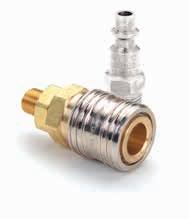
• 1/4” & 1/2” accept ISO 6150 B and A-A-59439 plugs/males
• 40 0 series accepts Tru-Flate Interchange
• Standard body material: Brass with nickel plated steel sleeve
• Standard seal material: Buna-N
• Optional seal materials: Silicone–138, FKM–143, EPDM–192
• General
• C onstruction
•
69 PNEUMATIC SPECIAL APPLICATIONS DIAGNOSTIC AGRICULTURE REFRIGERANT FLUID TRANSFER AND HYDRAULIC EATON Quick Disconnect Couplings Master Catalog E-MEQD-CC001-E8 August 2017
Series Body Size Max. Operating Pressure Min. Burst Pressure Rated Flow (in) (bar) (psi) (bar) (psi) (lpm) (gpm) 1000 1/4 138 2,000 552 8,000 679 179 400 3/8 69 1,000 276 4,000 1,274 336 500 1/2 35 500 140 2,000 2,038 538
Series
1000/400/500
Markets
Applications &
Pneumatics
Interchangeability All Sizes 1/4" & 1/2" 400 Series US Industrial Interchange ISO 6150 Series B Tru-Flate A-A-59439 (former MIL-C-4109) Flow Data Pressure Drop, psi Air Flow, scfm (100 psig Inlet Pressure) Page 69
Industrial Plants
Male NPTF Connections
§ Wi th Ball Check †With Bleeder Ball Check—Reduces Hose Whip *Nickel plated
Female NPTF Connections
†With Bleeder Ball Check—Reduces Hose Whip *Nickel plated
70 FLUID TRANSFER AND HYDRAULIC PNEUMATIC SPECIAL APPLICATIONS DIAGNOSTIC AGRICULTURE REFRIGERANT EATON Quick Disconnect Couplings Master Catalog E-MEQD-CC001-E8 August 2017 A B C D HEX HEX 1000 Series
1
2
Figure
Figure
Part Coupling Body Port Dimensions Number Type Size Size Thread Type Material Fig. A B Hex A B Hex (in) (in) (in) (mm) (mm) (mm) 900 Socket/Female 1/4 1/8 1/8-27 NPTF Brass 1 1.97 1.00 0.69 50.04 25.40 17.53 1100 Socket/Female 1/4 1/4 1/4-18 NPTF Brass 1 2.16 1.00 0.69 54.86 25.40 17.53 1300 Socket/Female 1/4 3/8 3/8-18 NPTF Brass 1 2.12 1.00 0.69 53.85 25.40 17.53 LL1100 Socket/Female 1/4 1/4 1/4-18 NPTF Stainless 1 2.16 1.00 0.69 54.86 25.40 17.53 Part Coupling Body Port Dimensions Number Type Size Size Thread Type Material Fig. C D Hex C D Hex (in) (in) (in) (mm) (mm) (mm) 10 Plug/Male 1/4 1/4 1/4-18 NPTF Steel 2 1.75 0.62 0.56 44.45 15.75 14.22 10C§ Plug/Male 1/4 1/4 1/4-18 NPTF Steel 2 1.75 0.65 0.56 44.45 16.51 14.22 10G† Plug/Male 1/4 1/4 1/4-18 NPTF Steel 2 1.75 0.65 0.56 44.45 16.51 14.22 12E Plug/Male 1/4 1/8 1/8-27 NPTF Steel 2 1.59 0.58 0.50 40.38 14.73 12.7 12G† Plug/Male 1/4 1/8 1/8-27 NPTF Steel 2 2.38 0.77 0.69 60.45 19.55 17.52 14 Plug/Male 1/4 3/8 3/8-18 NPTF Steel 2 1.75 0.79 0.69 44.45 20.06 17.52 14G† Plug/Male 1/4 3/8 3/8-18 NPTF Steel 2 2.53 0.77 0.69 64.26 19.55 17.52 B10 Plug/Male 1/4 1/4 1/4-18 NPTF Brass 2 1.75 0.62 0.56 44.45 16.25 14.22 LL10 Plug/Male 1/4 1/4 1/4-18 NPTF Stainless 2 1.75 0.62 0.56 44.45 16.51 14.22 10NK* Plug/Male 1/4 1/4 1/4-18 NPTF Steel 2 1.75 0.62 0.56 44.45 15.75 14.22
Part Coupling Body Port Dimensions Number Type Size Size Thread Type Material Fig. A B Hex A B Hex (in) (in) (in) (mm) (mm) (mm) 800E Socket/Female 1/4 1/8 1/8-27 NPTF Brass 3 1.86 1.00 0.69 47.24 25.40 17.53 1000E Socket/Female 1/4 1/4 1/4-18 NPTF Brass 3 2.08 1.00 0.69 52.83 25.40 17.53 1200 Socket/Female 1/4 3/8 3/8-18 NPTF Brass 3 2.16 1.00 0.75 54.86 25.40 19.05 LL1000 Socket/Female 1/4 1/4 1/4-18 NPTF Stainless 3 2.08 1.00 0.69 52.83 25.40 17.53 Part Coupling Body Port Dimensions Number Type Size Size Thread Type Material Fig. C D Hex C D Hex (in) (in) (in) (mm) (mm) (mm) 11 Plug/Male 1/4 1/4 1/4-18 NPTF Steel 4 1.63 0.79 0.69 41.40 20.07 17.53 11G† Plug/Male 1/4 1/4 1/4-18 NPTF Steel 4 2.44 0.77 0.69 61.98 19.56 17.53 13 Plug/Male 1/4 1/8 1/8-27 NPTF Steel 4 1.47 0.65 0.56 37.34 16.51 14.22 15E Plug/Male 1/4 3//8 3/8-18 NPTF Steel 4 1.69 0.94 0.81 42.93 23.88 20.57 11B Plug/Male 1/4 1/4 1/4-18 NPTF Brass 4 1.63 0.78 0.69 41.40 19.81 17.53 LL11 Plug/Male 1/4 1/4 1/4-18 NPTF Stainless 4 1.63 0.79 0.69 41.40 20.07 17.53 11NK* Plug/Male 1/4 1/4 1/4-18 NPTF Steel 4 1.63 0.79 0.69 41.40 20.07 17.53
A B C D HEX HEX
Figure 3
C D B A HEX HEX C D B A HEX HEX Page 70
Figure 4
Hose Stem End Connections
71 PNEUMATIC SPECIAL APPLICATIONS DIAGNOSTIC AGRICULTURE REFRIGERANT FLUID TRANSFER AND HYDRAULIC EATON Quick Disconnect Couplings Master Catalog E-MEQD-CC001-E8 August 2017 C D A B 1000 Series
Figure 5 Figure 6
Part Coupling Body Hose Dimensions Number Type Size I.D. Material Fig. A B A B (in) (in) (mm) (mm) 1600E Socket/Female 1/4 1/4 Brass 5 2.60 1.00 66.04 25.40 1600P‡ Socket/Female 1/4 1/4 Brass 5, 5A 2.37 1.00 60.20 25.40 1700E Socket/Female 1/4 3/8 Brass 5 2.60 1.00 66.04 25.40 1700P‡ Socket/Female 1/4 3/8 Brass 5, 5A 2.44 1.00 61.98 25.40 1800 Socket/Female 1/4 5/16 Brass 5 2.60 1.00 66.04 25.40 Par t Coupling Body Hose Dimensions Number Type Size I.D. Material Fig. C D C D (in) (in) (mm) (mm) 16 Plug/Male 1/4 1/4 Steel 6 2.22 0.50 56.39 12.70 16G† Plug/Male 1/4 1/4 Steel 6 2.97 0.77 75.44 19.56 16P‡ Plug/Male 1/4 1/4 Steel 6, 6A 2.00 0.58 50.80 14.73 17 Plug/Male 1/4 3/8 Steel 6 2.22 0.5 56.39 12.70 17G‡ Plug/Male 1/4 3/8 Steel 6 2.96 0.77 75.18 19.56 17P‡ Plug/Male 1/4 3/8 Steel 6, 6A 2.06 0.5 52.32 12.70 18E Plug/Male 1/4 5/16 Steel 6 2.22 0.50 56.39 12.70 B17 Plug/Male 1/4 3/8 Brass 6 2.22 0.5 56.39 12.70 16NK* Plug/Male 1/4 1/4 Steel 6 2.22 0.50 56.39 12.70 17NK* Plug/Male 1/4 3/8 Steel 6 2.22 0.5 56.39 12.70
ith Bleeder
Hose Whip ‡ For
plated 1600P 1700P 16P 17P
†W
Ball Check—Reduces
use with push-on style hose *Nickel
5A
6A 1600P1700P 16P 17P Page 71
Figure
Figure
Hose Clamp End Connections
72 FLUID TRANSFER AND HYDRAULIC PNEUMATIC SPECIAL APPLICATIONS DIAGNOSTIC AGRICULTURE REFRIGERANT EATON Quick Disconnect Couplings Master Catalog E-MEQD-CC001-E8 August 2017 D C A B HEX HEX 1000 Series
Figure 7 Figure 8
Part Coupling Body Hose Hose Dimensions Number Type Size I.D. O.D Material Fig. A B Hex A B Hex (in) (in) (in) (mm) (mm) (mm) 1SB1 Socket/Female 1/4 1/4 15/32 Brass 7 2.69 1.00 0.69 68.33 25.40 17.53 1SB3 Socket/Female 1/4 1/4 1/2 Brass 7 2.69 1.00 0.69 68.33 25.40 17.53 1SB5E Socket/Female 1/4 1/4 9/16 Brass 7 2.69 1.00 0.69 68.33 25.40 17.53 1SB7 Socket/Female 1/4 1/4 5/8 Brass 7 2.69 1.00 0.69 68.33 25.40 17.53 1SC5 Socket/Female 1/4 5/16 9/16 Brass 7 2.75 1.00 0.69 69.85 25.40 17.53 1SC7 Socket/Female 1/4 5/16 5/8 Brass 7 2.75 1.00 0.69 69.85 25.40 17.53 1SC9 Socket/Female 1/4 5/16 11/16 Brass 7 2.75 1.00 0.69 69.85 25.40 17.53 1SD5 Socket/Female 1/4 3/8 9/16 Brass 7 2.81 1.00 0.69 71.37 25.40 17.53 1SD7 Socket/Female 1/4 3/8 5/8 Brass 7 2.81 1.00 0.69 71.37 25.40 17.53 1SD9 Socket/Female 1/4 3/8 11/16 Brass 7 2.81 1.00 0.69 71.37 25.40 17.53 1SD11 Socket/Female 1/4 3/8 3/4 Brass 7 2.81 1.00 0.69 71.37 25.40 17.53 Part Coupling Body Hose Hose Dimensions Number Type Size I.D. O.D Material Fig. C D Hex C D Hex (in) (in) (in) (mm) (mm) (mm) 3PB1 Plug/Male 1/4 1/4 15/32 Steel 8 2.31 0.70 0.63 58.67 17.78 16.00 3PB3 Plug/Male 1/4 1/4 1/2 Steel 8 2.31 0.70 0.63 58.67 17.78 16.00 3PB5 Plug/Male 1/4 1/4 9/16 Steel 8 2.31 0.77 0.69 58.67 19.56 17.53 3PB7 Plug/Male 1/4 1/4 5/8 Steel 8 2.31 0.84 0.75 58.67 21.34 19.05 3PB9 Plug/Male 1/4 1/4 11/16 Steel 8 2.31 0.94 0.81 58.67 23.88 20.57 3PB11 Plug/Male 1/4 1/4 3/4 Steel 8 2.31 0.98 0.88 58.67 24.89 22.35 3PC5 Plug/Male 1/4 5/16 9/16 Steel 8 2.38 0.77 0.69 60.45 19.56 17.53 3PC7 Plug/Male 1/4 5/16 5/8 Steel 8 2.38 0.84 0.75 60.45 21.34 19.05 3PC9 Plug/Male 1/4 5/16 11/16 Steel 8 2.38 0.91 0.81 60.45 23.11 20.57 3PD5 Plug/Male 1/4 3/8 9/16 Steel 8 2.44 0.77 0.69 61.98 19.56 17.53 3PD7 Plug/Male 1/4 3/8 5/8 Steel 8 2.44 0.84 0.75 61.98 21.34 19.05 3PD9 Plug/Male 1/4 3/8 11/16 Steel 8 2.44 0.91 0.81 61.98 23.11 20.57 3PD11 Plug/Male 1/4 3/8 3/4 Steel 8 2.44 1.01 0.88 61.98 25.65 22.35 Page 72
Male NPTF Connections
†W ith Bleeder Ball Check—Reduces Hose Whip *Nickel
Female NPTF Connections
†W ith Bleeder Ball Check—Reduces Hose Whip *Nickel plated
73 PNEUMATIC SPECIAL APPLICATIONS DIAGNOSTIC AGRICULTURE REFRIGERANT FLUID TRANSFER AND HYDRAULIC EATON Quick Disconnect Couplings Master Catalog E-MEQD-CC001-E8 August 2017
Part Coupling Body Port Dimensions Number Type Size Size Thread Type Material Fig. A B Hex A B Hex (in) (in) (in) (mm) (mm) (mm) 410 Socket/Female 3/8 1/4 1/4-18 NPTF Brass 1 2.35 1.13 0.88 59.69 28.70 22.35 430 Socket/Female 3/8 3/8 3/8-18 NPTF Brass 1 2.35 1.13 0.88 59.69 28.70 22.35 450 Socket/Female 3/8 1/2 1/2-14 NPTF Brass 1 2.54 1.13 0.88 64.52 28.70 22.35 Par t Coupling Body Port Dimensions Number Type Size Size Thread Type Material Fig. C D Hex C D Hex (in) (in) (in) (mm) (mm) (mm) 38 Plug/Male 3/8 1/8 1/8-27 NPTF Steel 2 1.72 0.72 0.63 43.69 18.29 16.00 40 Plug/Male 3/8 1/4 1/4-18 NPTF Steel 2 1.88 0.72 0.63 47.75 18.29 16.00 40NK* Plug/Male 3/8 1/4 1/4-18 NPTF Steel 2 1.88 0.72 0.63 47.75 18.29 16.00 40G† Plug/Male 3/8 1/4 1/4-18 NPTF Steel 2 2.65 0.77 0.69 67.31 19.56 17.53 42 Plug/Male 3/8 3/8 3/8-18 NPTF Steel 2 1.88 0.79 0.69 47.75 20.07 17.53 42G† Plug/Male 3/8 3/8 3/8-18 NPTF Steel 2 2.65 0.77 0.69 67.31 19.56 17.53 44 Plug/Male 3/8 1/2 1/2-14 NPTF Steel 2 2.09 1.01 0.88 53.09 25.65 22.35 B40 Plug/Male 3/8 1/4 1/4-18 NPTF Brass 2 1.88 0.70 0.63 47.75 17.78 16.00 B42 Plug/Male 3/8 3/8 3/8-18 NPTF Brass 2 1.88 0.77 0.69 47.75 19.56 17.53 31AP25M Plug/Male 3/8 1/4 1/4-18 NPTF Steel 2A 1.85 0.72 0.63 46.99 18.29 16.00 31AP37M Plug/Male 3/8 3/8 3/8-18 NPTF Steel 2A 1.85 0.79 0.69 46.99 20.07 17.53
plated
Part Coupling Body Port Dimensions Number Type Size Size Thread Type Material Fig. A B Hex A B Hex (in) (in) (in) (mm) (mm) (mm) 400 Socket/Female 3/8 1/4 1/4-18 NPTF Brass 3 2.10 1.13 0.88 53.34 28.70 22.35 420 Socket/Female 3/8 3/8 3/8-18 NPTF Brass 3 2.35 1.13 0.88 59.69 28.70 22.35 440 Socket/Female 3/8 1/2 1/2-14 NPTF Brass 3 2.62 1.13 1.00 66.55 28.70 25.40 Par t Coupling Body Port Dimensions Number Type Size Size Thread Type Material Fig. C D Hex C D Hex (in) (in) (in) (mm) (mm) (mm) 41 Plug/Male 3/8 1/4 1/4-18 NPTF Steel 4 1.63 0.79 0.69 41.40 20.07 17.53 41NK* Plug/Male 3/8 1/4 1/4-18 NPTF Steel 4 1.63 0.79 0.69 41.40 20.07 17.53 41G† Plug/Male 3/8 1/4 1/4-18 NPTF Steel 4 2.56 0.77 0.69 65.02 19.56 17.53 43 Plug/Male 3/8 3/8 3/8-18 NPTF Steel 4 1.81 0.94 0.81 45.97 23.88 20.57 43G† Plug/Male 3/8 3/8 3/8-18 NPTF Steel 4 2.62 0.84 0.75 66.55 21.34 19.05 45E Plug/Male 3/8 1/2 1/2-14 NPTF Steel 4 2.06 1.15 1.00 52.32 29.21 25.40 B43 Plug/Male 3/8 3/8 3/8-18 NPTF Brass 4 1.81 0.91 0.81 45.97 23.11 20.57 31AP25F Plug/Male 3/8 1/4 1/4-18 NPTF Steel 4A 1.60 0.79 0.69 40.64 20.07 17.53 31AP37F Plug/Male 3/8 3/8 3/8-18 NPTF Steel 4A 1.78 0.94 0.81 45.21 23.88 20.57
400
Figure
Figure
Figure
Figure
Figure
Figure
Page 73
Series
1
2
3
4
2A
4A
Hose Stem End Connections
Hose Clamp End Connections

74 FLUID TRANSFER AND HYDRAULIC PNEUMATIC SPECIAL APPLICATIONS DIAGNOSTIC AGRICULTURE REFRIGERANT EATON Quick Disconnect Couplings Master Catalog E-MEQD-CC001-E8 August 2017
Part Coupling Body Hose Dimensions Number Type Size I.D. Material Fig. A B A B (in) (in) (mm) (mm) 4004E Socket/Female 3/8 1/4 Brass 5 2.82 1.13 71.63 28.70 4050E Socket/Female 3/8 5/16 Brass 5 2.82 1.13 71.63 28.70 4006E Socket/Female 3/8 3/8 Brass 5 2.82 1.13 71.63 28.70 4008E Socket/Female 3/8 1/2 Brass 5 2.82 1.13 71.63 28.70 Par t Coupling Body Hose Dimensions Number Type Size I.D. Material Fig. C D C D (in) (in) (mm) (mm) 404 Plug/Male 3/8 1/4 Steel 6 2.34 0.72 59.44 18.29 406 Plug/Male 3/8 3/8 Steel 6 2.34 0.63 59.44 16.00 408 Plug/Male 3/8 1/2 Steel 6 2.34 0.81 59.44 20.57 B406E Plug/Male 3/8 3/8 Brass 6 2.34 0.63 59.44 16.00
Part Coupling Body Hose Hose Dimensions Number Type Size I.D. O.D. Material Fig. A B Hex A B Hex (in) (in) (in) (mm) (mm) (mm) 40SD7 Socket/Female 3/8 3/8 5/8 Brass 7 3.04 1.13 0.75 77.22 28.70 19.05 40SD9 Socket/Female 3/8 3/8 11/16 Brass 7 3.04 1.13 0.81 77.22 28.70 20.57 40SD11 Socket/Female 3/8 3/8 3/4 Brass 7 3.04 1.13 0.88 77.22 28.70 22.35 40SP13 Socket/Female 3/8 1/2 13/16 Brass 7 3.67 1.13 0.94 93.22 28.70 23.88 40SP15 Socket/Female 3/8 1/2 7/8 Brass 7 3.67 1.13 1.00 93.22 28.70 25.40 40SP17 Socket/Female 3/8 1/2 5/16 Brass 7 3.67 1.13 1.00 93.22 28.70 25.40 40SP19 Socket/Female 3/8 1/2 1 Brass 7 3.67 1.13 1.13 93.22 28.70 28.70 Par t Coupling Body Hose Hose Dimensions Number Type Size I.D. O.D. Material Fig. C D Hex C D Hex (in) (in) (in) (mm) (mm) (mm) 4PB3 Plug/Male 3/8 1/4 1/2 Steel 8 2.44 0.70 0.63 61.98 17.78 16.00 4PB5 Plug/Male 3/8 1/4 9/16 Steel 8 2.44 0.77 0.69 61.98 19.56 17.53 4PB7 Plug/Male 3/8 1/4 5/8 Steel 8 2.44 0.84 0.75 61.98 21.34 19.05 4PD7 Plug/Male 3/8 3/8 5/8 Steel 8 2.56 0.84 0.75 65.02 21.34 19.05 4PD9 Plug/Male 3/8 3/8 11/16 Steel 8 2.56 0.91 0.81 65.02 23.11 20.57 4PD11 Plug/Male 3/8 3/8 3/4 Steel 8 2.56 0.98 0.88 65.02 24.89 22.35 4PD15 Plug/Male 3/8 3/8 7/8 Steel 8 2.56 1.12 1.00 65.02 28.45 25.40 4PP13 Plug/Male 3/8 1/2 13/16 Steel 8 3.25 1.05 0.94 82.55 26.67 23.88 4PP15 Plug/Male 3/8 1/2 7/8 Steel 8 3.25 1.12 1.00 82.55 28.45 25.40 4PP19 Plug/Male 3/8 1/2 1 Steel 8 3.25 1.26 1.13 82.55 32.00 28.58 Dust Plugs Series Dust Plug Number 1000 PSDC1HK 400 PSDC2HK 400 Series
Figure 5
Figure 6
Figure 7
Vinyl Dust Plug Page 74
Figure 8
500 Series
Male End Connections
†W ith Bleeder Ball Check—Reduces Hose Whip
75 PNEUMATIC SPECIAL APPLICATIONS DIAGNOSTIC AGRICULTURE REFRIGERANT FLUID TRANSFER AND HYDRAULIC EATON Quick Disconnect Couplings Master Catalog E-MEQD-CC001-E8 August 2017
Part Coupling Body Por t Dimensions Number Type Size Size Thread Type Material Fig. A B Hex A B Hex (in) (in) (in) (mm) (mm) (mm) 501 Socket/Female 1/2 1/4 1/4-18 NPTF Brass 1 2.77 1.19 1.00 70.36 30.23 25.40 510 Socket/Female 1/2 3/8 3/8-18 NPTF Brass 1 2.78 1.19 1.00 70.61 30.23 25.40 530E Socket/Female 1/2 1/2 1/2-14 NPTF Brass 1 2.97 1.19 1.00 75.44 30.23 25.40 550 Socket/Female 1/2 3/4 3/4-14 NPTF Brass 1 2.97 1.19 1.06 75.44 30.23 26.92 530143 Socket/Female 1/2 1/2 1/2-14 NPTF Brass 1 2.97 1.19 1.00 75.44 30.23 25.40 550NV Socket/Female 1/2 3/4 3/4-14 NPTF Brass 1 2.97 1.19 1.06 75.44 30.23 26.92 Part Coupling Body Por t Dimensions Number Type Size Size Thread Type Material Fig. C D Hex C D Hex (in) (in) (in) (mm) (mm) (mm) 50E Plug/Male 1/2 1/4 1/4-18 NPTF Steel 2 2.25 0.79 0.69 57.15 20.07 17.53 50G† Plug/Male 1/2 1/4 1/4-18 NPTF Steel 2 2.90 0.98 0.88 73.66 24.89 22.35 52 Plug/Male 1/2 3/8 3/8-18 NPTF Steel 2 2.25 0.87 0.75 57.15 22.10 19.05 52G† Plug/Male 1/2 3/8 3/8-18 NPTF Steel 2 2.90 0.98 0.88 73.66 24.89 22.35 54E Plug/Male 1/2 1/2 1/2-14 NPTF Steel 2 2.44 1.01 0.88 61.98 25.65 22.35 54G† Plug/Male 1/2 1/2 1/2-14 NPTF Steel 2 3.09 0.98 0.88 78.49 24.89 22.35 56 Plug/Male 1/2 3/4 3/4-14 NPTF Steel 2 2.50 1.23 1.06 63.50 31.24 26.92 56G† Plug/Male 1/2 3/4 3/4-14 NPTF Steel 2 3.14 1.19 1.06 79.76 30.23 26.92 B52 Plug/Male 1/2 3/8 3/8-18 NPTF Brass 2 2.25 0.87 0.75 57.15 22.10 19.05 B54 Plug/Male 1/2 1/2 1/2-14 NPTF Brass 2 2.44 1.01 0.88 61.98 25.65 22.35 †W ith Bleeder Ball Check—Reduces Hose Whip
End Connections Part Coupling Body Por t Dimensions Number Type Size Size Thread Type Material Fig. A B Hex A B Hex (in) (in) (in) (mm) (mm) (mm) 500A Socket/Female 1/2 1/4 1/4-18 NPTF Brass 3 2.72 1.19 1.00 69.1 30.2 25.4 500 Socket/Female 1/2 3/8 3/8-18 NPTF Brass 3 2.78 1.19 1.00 70.6 30.2 25.4 520 Socket/Female 1/2 1/2 1/2-14 NPTF Brass 3 3.06 1.19 1.00 77.7 30.2 25.4 540 Socket/Female 1/2 3/4 3/4-14 NPTF Brass 3 3.09 1.19 1.19 78.5 30.2 30.2 Par t Coupling Body Por t Dimensions Number Type Size Size Thread Type Material Fig. C D Hex C D Hex (in) (in) (in) (mm) (mm) (mm) 53A Plug/Male 1/2 1/4 1/4-18 NPTF Steel 4 1.92 0.79 0.69 48.8 20.1 17.5 53 Plug/Male 1/2 3/8 3/8-18 NPTF Steel 4 2.06 0.94 0.81 52.3 23.9 20.6 53G† Plug/Male 1/2 3/8 3/8-18 NPTF Steel 4 2.90 0.98 0.88 73.7 24.9 22.4 55 Plug/Male 1/2 1/2 1/2-14 NPTF Steel 4 2.34 1.15 1.00 59.4 29.2 25.4 55G† Plug/Male 1/2 1/2 1/2-14 NPTF Steel 4 3.17 1.15 1.00 80.5 29.2 25.4 57 Plug/Male 1/2 3/4 3/4-14 NPTF Steel 4 2.44 1.37 1.19 62.0 34.8 30.2
Female
Figure 1
Figure 2
Figure 3
Page 75
Figure 4
Hose Stem End Connections
Hose Clamp End Connections
76 FLUID TRANSFER AND HYDRAULIC PNEUMATIC SPECIAL APPLICATIONS DIAGNOSTIC AGRICULTURE REFRIGERANT EATON Quick Disconnect Couplings Master Catalog E-MEQD-CC001-E8 August 2017
Part Coupling Body Hose Dimensions Number Type Size I.D. Material Fig. A B A B (in) (in) (mm) (mm) 570 Socket/Female 1/2 3/8 Brass 5 3.32 1.19 84.3 30.2 580 Socket/Female 1/2 1/2 Brass 5 3.24 1.19 82.3 30.2 590 Socket/Female 1/2 3/4 Brass 5 4.09 1.19 103.9 30.2 Par t Coupling Body Hose Dimensions Number Type Size I.D. Material Fig. C D C D (in) (in) (mm) (mm) 585 Plug/Male 1/2 5/16 Steel 6 2.66 0.69 67.6 17.5 585G† Plug/Male 1/2 5/16 Brass 6 3.37 0.98 85.6 24.9 59 Plug/Male 1/2 3/8 Steel 6 2.66 0.69 67.6 17.5 59G† Plug/Male 1/2 3/8 Brass 6 3.37 0.98 85.6 24.9 60 Plug/Male 1/2 1/2 Steel 6 2.66 0.75 67.6 19.1 60G† Plug/Male 1/2 1/2 Brass 6 3.37 0.98 85.6 24.9 61E Plug/Male 1/2 3/4 Steel 6 3.50 1.00 88.9 25.4 61G† Plug/Male 1/2 3/4 Brass 6 4.22 1.00 107.2 25.4 †W ith Bleeder Ball Check—Reduces Hose Whip
Part Coupling Body Hose Hose Dimensions Number Type Size I.D. O.D Material Fig. A B Hex A B Hex (in) (in) (in) (mm) (mm) (mm) 50SP13 Socket/Female 1/2 1/2 13/16 Brass 7 4.09 1.19 0.94 103.9 30.2 23.9 50SP15 Socket/Female 1/2 1/2 7/8 Brass 7 4.09 1.19 1.00 103.9 30.2 25.4 5019E Socket/Female 1/2 1/2 1 Brass 7 4.09 1.26 1.13 103.9 32.0 28.7 50SR23 Socket/Female 1/2 3/4 1 1/8 Brass 7 4.22 1.19 1.25 107.2 30.2 31.8 50SR25 Socket/Female 1/2 3/4 1 3/16 Brass 7 4.22 1.19 1.31 107.2 30.2 33.3 50SR27 Socket/Female 1/2 3/4 1 1/4 Brass 7 4.22 1.19 1.38 107.2 30.2 35.1 Par t Coupling Body Hose Hose Dimensions Number Type Size I.D. O.D Material Fig. C D Hex C D Hex (in) (in) (in) (mm) (mm) (mm) 5PB3 Plug/Male 1/2 1/4 1/2 Steel 8 2.81 0.70 0.63 71.4 17.8 16.0 5PB5 Plug/Male 1/2 1/4 9/16 Steel 8 2.81 0.77 0.69 71.4 19.6 17.5 5PB7 Plug/Male 1/2 1/4 5/8 Steel 8 2.81 0.84 0.75 71.4 21.3 19.1 5PD5 Plug/Male 1/2 3/8 9/16 Steel 8 2.94 0.77 0.69 74.7 19.6 17.5 5PD7 Plug/Male 1/2 3/8 5/8 Steel 8 2.94 0.84 0.75 74.7 21.3 19.1 5PD9 Plug/Male 1/2 3/8 11/16 Steel 8 2.94 0.91 0.81 74.7 23.1 20.6 5PD11 Plug/Male 1/2 3/8 3/4 Steel 8 2.94 0.98 0.88 74.7 24.9 22.4 5PD13 Plug/Male 1/2 3/8 13/16 Steel 8 2.94 1.05 0.94 74.7 26.7 23.9 5PP13 Plug/Male 1/2 1/2 13/16 Steel 8 3.62 1.05 0.94 91.9 26.7 23.9 5PP15 Plug/Male 1/2 1/2 7/8 Steel 8 3.62 1.12 1.00 91.9 28.4 25.4 5PR23 Plug/Male 1/2 3/4 1 1/8 Steel 8 3.75 1.40 1.25 95.3 35.6 31.8 5PR25 Plug/Male 1/2 3/4 1 3/16 Steel 8 3.75 1.47 1.31 95.3 37.3 33.3 5PR27 Plug/Male 1/2 3/4 1 1/4 Steel 8 3.75 1.54 1.38 95.3 39.1 35.1 500
Series
Figure 5 Figure 6
Page 76
Figure 7 Figure 8
3000/4000/5000/6000 Series
Eaton’s 3000/4000/5000/6000 Series Industrial Interchange pin lock pneumatic quick disconnect couplings are designed for compressed air, gases, and liquids. This series sets the industry standard for pin lock style pneumatic couplings.
Product Features
• Easy, automatic, push-to-connect design provides instantaneous connection and disconnection of lines, plus automatic shut-off of socket/female end of line
Physical Characteristics
• All sizes accept US industrial Interchange; 1/4” & 1/2” also accept ISO 6150 Series B and A-A-59439 plugs/males
• Optional sleeve lock option prevents accidental disconnection
• Standard body material: Brass
• Standard seal material: Buna-N
• Optional seal and valve materials: Silicone–138, FKM–143, EPDM–192

Applications & Markets
• Industrial Breathing Air
• General Pneumatics
• Maintenance & Repair
• Fluid Transfer
77 PNEUMATIC SPECIAL APPLICATIONS DIAGNOSTIC AGRICULTURE REFRIGERANT FLUID TRANSFER AND HYDRAULIC EATON Quick Disconnect Couplings Master Catalog E-MEQD-CC001-E8 August 2017
Series Body Size Max. Operating Pressure Min. Burst Pressure Rated Flow (in) (bar) (psi) (bar) (psi) (lpm) scfm 3000 1/4 138 2,000 552 8,000 680 24 4000 3/8 69 1,000 276 4,000 1,274 45 5000 1/2 35 500 140 2,000 2,040 72 6000 3/4 15 220 60 880 3,540 125
Interchangeability All Sizes 1/4" & 1/2" US Industrial Interchange ISO 6150 Series B A-A-59439 (former MIL-C-4109) Flow Data Pressure Drop, psi Air Flow, scfm (100 psig Inlet Pressure) Page 77
Male End Connections
Female End Connections
78 FLUID TRANSFER AND HYDRAULIC PNEUMATIC SPECIAL APPLICATIONS DIAGNOSTIC AGRICULTURE REFRIGERANT EATON Quick Disconnect Couplings Master Catalog E-MEQD-CC001-E8 August 2017
Part Coupling Body Port Dimensions Number Type Size Size Thread Type Material Fig. A B Hex A B Hex (in) (in) (in) (mm) (mm) (mm) 2900 Socket/Female 1/4 1/8 1/8-27 NPTF Brass 1 2.00 1.19 0.69 50.80 30.23 17.53 3100E Socket/Female 1/4 1/4 1/4-18 NPTF Brass 1 2.19 1.19 0.69 55.63 30.23 17.53 3300E Socket/Female 1/4 3/8 3/8-18 NPTF Brass 1 2.15 1.19 0.69 54.61 30.23 17.53 300043* Socket/Female 1/4 7/16 7/16-20 UNF Brass 1 2.10 1.19 0.69 53.34 30.23 17.53 Par t Coupling Body Port Dimensions Number Type Size Size Thread Type Material Fig. C D Hex C D Hex (in) (in) (in) (mm) (mm) (mm) 10 Plug/Male 1/4 1/4 1/4-18 NPTF Steel 2 1.75 0.62 0.56 44.45 15.85 14.22 10C§ Plug/Male 1/4 1/4 1/4-18 NPTF Steel 2 1.75 0.65 0.56 44.45 16.51 14.22 10G† Plug/Male 1/4 1/4 1/4-18 NPTF Steel 2 1.75 0.65 0.56 44.45 16.51 14.22 12E Plug/Male 1/4 1/8 1/8-27 NPTF Steel 2 1.59 0.58 0.50 40.39 14.73 12.70 12G† Plug/Male 1/4 1/8 1/8-27 NPTF Steel 2 2.38 0.77 0.69 60.45 19.56 17.53 14 Plug/Male 1/4 3/8 3/8-18 NPTF Steel 2 1.75 0.79 0.69 44.45 20.07 17.53 14G† Plug/Male 1/4 3/8 3/8-18 NPTF Steel 2 2.53 0.77 0.69 64.26 19.56 17.53 B10 Plug/Male 1/4 1/4 1/4-18 NPTF Brass 2 1.75 0.62 0.56 44.45 15.75 14.22 LL10 Plug/Male 1/4 1/4 1/4-18 NPTF Stainless 2 1.75 0.62 0.56 44.45 15.85 14.22 10NK** Plug/Male 1/4 1/4 1/4-18 NPTF Steel 2 1.75 0.62 0.56 44.45 15.75 14.22 *45° Male Flare § Wi th Ball Check †W ith Bleeder Ball
Hose Whip **Nickel plated
Check—Reduces
Part Coupling Body Port Dimensions Number Type Size Size Thread Type Material Fig. A B Hex A B Hex (in) (in) (in) (mm) (mm) (mm) 2800 Socket/Female 1/4 1/8 1/8-27 NPTF Brass 3 1.89 1.19 0.69 48.01 30.23 17.53 3000 Socket/Female 1/4 1/4 1/4-18 NPTF Brass 3 2.11 1.19 0.69 53.59 30.23 17.53 3200 Socket/Female 1/4 3/8 3/8-18 NPTF Brass 3 2.19 1.19 0.75 55.63 30.23 19.05 Part Coupling Body Port Dimensions Number Type Size Size Thread Type Material Fig. C D Hex C D Hex (in) (in) (in) (mm) (mm) (mm) 11 Plug/Male 1/4 1/4 1/4-18 NPTF Steel 4 1.63 0.79 0.69 41.40 20.07 17.53 11G† Plug/Male 1/4 1/4 1/4-18 NPTF Steel 4 2.44 0.77 0.69 61.98 19.56 17.53 13 Plug/Male 1/4 1/8 1/8-27 NPTF Steel 4 1.47 0.65 0.56 37.34 16.51 14.22 15E Plug/Male 1/4 3/8 3/8-18 NPTF Steel 4 1.69 0.94 0.81 42.93 23.88 20.57 11B Plug/Male 1/4 1/4 1/4-18 NPTF Brass 4 1.63 0.79 0.69 41.40 20.07 17.53 LL11 Plug/Male 1/4 1/4 1/4-18 NPTF Stainless 4 1.63 0.79 0.69 41.40 20.07 17.53 11NK* Plug/Male 1/4 1/4 1/4-18 NPTF Steel 4 1.63 0.79 0.69 41.40 20.07 17.53 †W ith Bleeder Ball Check—Reduces Hose Whip *Nickel plated A C D B HEX HEX C D B A HEX HEX 3000 Series Figure 1 Figure 2 Figure 3 Figure 4 A C D B HEX HEX C D B A HEX HEX Page 78
79 PNEUMATIC SPECIAL APPLICATIONS DIAGNOSTIC AGRICULTURE REFRIGERANT FLUID TRANSFER AND HYDRAULIC EATON Quick Disconnect Couplings Master Catalog E-MEQD-CC001-E8 August 2017 C D A B 3000 Series
C D A B
Part Coupling Body Hose Dimensions Number Type Size I.D. Material Fig. A B A B (in) (in) (mm) (mm) 3600 Socket/Female 1/4 1/4 Brass 5 2.63 1.19 66.80 30.23 3600P‡ Socket/Female 1/4 1/4 Brass 5, 5A 2.40 1.19 60.96 30.23 3700E Socket/Female 1/4 3/8 Brass 5 2.63 1.19 66.80 30.23 3700P‡ Socket/Female 1/4 3/8 Brass 5, 5A 2.47 1.19 62.74 30.23 3800 Socket/Female 1/4 5/16 Brass 5 2.63 1.19 66.80 30.23 Par t Coupling Body Hose Dimensions Number Type Size I.D. Material Fig. C D C D (in) (in) (mm) (mm) 16 Plug/Male 1/4 1/4 Steel 6 2.22 0.50 56.39 12.70 16G† Plug/Male 1/4 1/4 Steel 6 2.97 0.77 75.44 19.56 16P‡ Plug/Male 1/4 1/4 Steel 6, 6A 2.00 0.58 50.80 14.73 17 Plug/Male 1/4 3/8 Steel 6 2.22 0.50 56.39 12.70 17G† Plug/Male 1/4 3/8 Steel 6 2.96 0.77 75.18 19.56 17P‡ Plug/Male 1/4 3/8 Steel 6, 6A 2.06 0.5 52.32 12.70 18E Plug/Male 1/4 5/16 Steel 6 2.22 0.50 56.39 12.70 B17 Plug/Male 1/4 3/8 Brass 6 2.22 0.50 56.39 12.70 16NK* Plug/Male 1/4 1/4 Steel 6 2.22 0.5 56.39 12.70 17NK* Plug/Male 1/4 3/8 Steel 6 2.22 0.5 56.39 12.70 †W ith Bleeder Ball Checkv—Reduces Hose Whip ‡ For use with push-on style hose *Nickel plated 3600P 3700P 16P 17P Figure 5A Figure 6A 3600P3700P 16P 17P Page 79
Figure 5 Figure 6
Hose Stem End Connections
Hose Clamp End Connections
80 FLUID TRANSFER AND HYDRAULIC PNEUMATIC SPECIAL APPLICATIONS DIAGNOSTIC AGRICULTURE REFRIGERANT EATON Quick Disconnect Couplings Master Catalog E-MEQD-CC001-E8 August 2017 D C A B HEX HEX 3000 Series Figure 7 Figure 8 D C A B HEX HEX
Part Coupling Body Hose Hose Dimensions Number Type Size I.D. O.D Material Fig. A B Hex A B Hex (in) (in) (in) (mm) (mm) (mm) 3SA0 Socket/Female 1/4 3/16 7/16 Brass 7 2.65 1.19 0.56 67.31 30.23 14.22 3SB1 Socket/Female 1/4 1/4 15/32 Brass 7 2.72 1.19 0.63 69.09 30.23 16.00 3SB3 Socket/Female 1/4 1/4 1/2 Brass 7 2.72 1.19 0.63 69.09 30.23 16.00 3SB5 Socket/Female 1/4 1/4 9/16 Brass 7 2.72 1.19 0.69 69.09 30.23 17.53 3SB7 Socket/Female 1/4 1/4 5/8 Brass 7 2.72 1.19 0.75 69.09 30.23 19.05 3SB9 Socket/Female 1/4 1/4 11/16 Brass 7 2.72 1.19 0.81 69.09 30.23 20.57 3SC5 Socket/Female 1/4 5/16 9/16 Brass 7 2.78 1.19 0.69 70.61 30.23 17.53 3SC7 Socket/Female 1/4 5/16 5/8 Brass 7 2.78 1.19 0.75 70.61 30.23 19.05 3SC9 Socket/Female 1/4 5/16 11/16 Brass 7 2.78 1.19 0.81 70.61 30.23 20.57 3SD5 Socket/Female 1/4 3/8 9/16 Brass 7 2.84 1.19 0.69 72.14 30.23 17.53 3SD7 Socket/Female 1/4 3/8 5/8 Brass 7 2.84 1.19 0.75 72.14 30.23 19.05 3SD9 Socket/Female 1/4 3/8 11/16 Brass 7 2.84 1.19 0.81 72.14 30.23 20.57 3SD11 Socket/Female 1/4 3/8 3/4 Brass 7 2.84 1.19 0.88 72.14 30.23 22.35 Par t Coupling Body Hose Hose Dimensions Number Type Size I.D. O.D. Material Fig. C D Hex C D Hex (in) (in) (in) (mm) (mm) (mm) 3PB1 Plug/Male 1/4 1/4 15/32 Steel 8 2.31 0.70 0.63 58.67 17.78 16.00 3PB3 Plug/Male 1/4 1/4 1/2 Steel 8 2.31 0.70 0.63 58.67 17.78 16.00 3PB5 Plug/Male 1/4 1/4 9/16 Steel 8 2.31 0.77 0.69 58.67 19.56 17.53 3PB7 Plug/Male 1/4 1/4 5/8 Steel 8 2.31 0.84 0.75 58.67 21.34 19.05 3PB9 Plug/Male 1/4 1/4 11/16 Steel 8 2.31 0.91 0.81 58.67 23.11 20.57 3PB11 Plug/Male 1/4 1/4 3/4 Steel 8 2.31 0.98 0.88 58.67 24.89 22.35 3PC5 Plug/Male 1/4 5/16 9/16 Steel 8 2.38 0.77 0.69 60.45 19.56 17.53 3PC7 Plug/Male 1/4 5/16 5/8 Steel 8 2.38 0.84 0.75 60.45 21.34 19.05 3PC9 Plug/Male 1/4 5/16 11/16 Steel 8 2.38 0.91 0.81 60.45 23.11 20.57 3PD5 Plug/Male 1/4 3/8 9/16 Steel 8 2.44 0.77 0.69 61.98 19.56 17.53 3PD7 Plug/Male 1/4 3/8 5/8 Steel 8 2.44 0.84 0.75 61.98 21.34 19.05 3PD9 Plug/Male 1/4 3/8 11/16 Steel 8 2.44 0.91 0.81 61.98 23.11 20.57 3PD11 Plug/Male 1/4 3/8 3/4 Steel 8 2.44 0.98 0.88 61.98 24.89 22.35 Page 80
Male End Connections
†W ith Bleeder Ball Check—Reduces Hose Whip *Nickel
Female End Connections
81 PNEUMATIC SPECIAL APPLICATIONS DIAGNOSTIC AGRICULTURE REFRIGERANT FLUID TRANSFER AND HYDRAULIC EATON Quick Disconnect Couplings Master Catalog E-MEQD-CC001-E8 August 2017
Part Coupling Body Port Dimensions Number Type Size Size Thread Type Material Fig. A B Hex A B Hex (in) (in) (in) (mm) (mm) (mm) 4100A Socket/Female 3/8 1/8 1/8-27 NPTF Brass 1 2.20 1.38 0.88 55.88 35.05 22.35 4100 Socket/Female 3/8 1/4 1/4-18 NPTF Brass 1 2.35 1.38 0.88 59.69 35.05 22.35 4300 Socket/Female 3/8 3/8 3/8-18 NPTF Brass 1 2.35 1.38 0.88 59.69 35.05 22.35 4500E Socket/Female 3/8 1/2 1/2-14 NPTF Brass 1 2.54 1.38 0.88 64.52 35.05 22.35 Par t Coupling Body Port Dimensions Number Type Size Size Thread Type Material Fig. C D Hex C D Hex (in) (in) (in) (mm) (mm) (mm) 38 Plug/Male 3/8 1/8 1/8-27 NPTF Steel 2 1.72 0.72 0.63 43.69 18.29 16.00 40 Plug/Male 3/8 1/4 1/4-18 NPTF Steel 2 1.88 0.72 0.63 47.75 18.29 16.00 40G† Plug/Male 3/8 1/4 1/4-18 NPTF Steel 2 2.65 0.77 0.69 67.31 19.56 17.53 42 Plug/Male 3/8 3/8 3/8-18 NPTF Steel 2 1.88 0.79 0.69 47.75 20.07 17.53 42G† Plug/Male 3/8 3/8 3/8-18 NPTF Steel 2 2.65 0.77 0.69 67.31 19.56 17.53 44 Plug/Male 3/8 1/2 1/2-14 NPTF Steel 2 2.09 1.01 0.88 53.09 25.65 22.35 B40 Plug/Male 3/8 1/4 1/4-18 NPTF Brass 2 1.88 0.70 0.63 47.75 17.78 16.00 B42 Plug/Male 3/8 3/8 3/8-18 NPTF Brass 2 1.88 0.77 0.69 47.75 19.56 17.53 40NK* Plug/Male 3/8 1/4 1/4-18 NPTF Steel 2 1.88 0.72 0.63 47.75 18.29 16.00
plated
Part Coupling Body Port Dimensions Number Type Size Size Thread Type Material Fig. A B Hex A B Hex (in) (in) (in) (mm) (mm) (mm) 4000A Socket/Female 3/8 1/8 1/8-27 NPTF Brass 3 2.10 1.38 0.88 53.34 35.05 22.35 4000 Socket/Female 3/8 1/4 1/4-18 NPTF Brass 3 2.10 1.38 0.88 53.34 35.05 22.35 4200 Socket/Female 3/8 3/8 3/8-18 NPTF Brass 3 2.35 1.38 0.88 59.69 35.05 22.35 4400 Socket/Female 3/8 1/2 1/2-14 NPTF Brass 3 2.62 1.38 1 66.55 35.05 25.40 Par t Coupling Body Port Dimensions Number Type Size Size Thread Type Material Fig. C D Hex C D Hex (in) (in) (in) (mm) (mm) (mm) 41 Plug/Male 3/8 1/4 1/4-18 NPTF Steel 4 1.63 0.79 0.69 41.40 20.07 17.53 41G† Plug/Male 3/8 1/4 1/4-18 NPTF Steel 4 2.56 0.77 0.69 65.02 19.56 17.53 43 Plug/Male 3/8 3/8 3/8-18 NPTF Steel 4 1.81 0.94 0.81 45.97 23.88 20.57 43G† Plug/Male 3/8 3/8 3/8-18 NPTF Steel 4 2.62 0.84 0.75 66.55 21.34 19.05 45E Plug/Male 3/8 1/2 1/2-14 NPTF Steel 4 2.06 1.15 1 52.32 29.21 25.40 B43 Plug/Male 3/8 3/8 3/8-18 NPTF Brass 4 1.81 0.91 0.81 45.97 23.11 20.57 41NK* Plug/Male 3/8 1/4 1/4-18 NPTF Steel 4 1.63 0.79 0.69 41.40 20.07 17.53 †W ith Bleeder Ball Check—Reduces Hose Whip *Nickel plated A C D B HEX HEX C D B A HEX HEX 4000 Series Figure 1 Figure 2 Figure 3 Figure 4 A C D B HEX HEX C D B A HEX HEX Page 81
82 FLUID TRANSFER AND HYDRAULIC PNEUMATIC SPECIAL APPLICATIONS DIAGNOSTIC AGRICULTURE REFRIGERANT EATON Quick Disconnect Couplings Master Catalog E-MEQD-CC001-E8 August 2017 C D A B D C A B HEX HEX 4000 Series
Figure 5
C D A B D C A B HEX HEX Hose Stem End Connections Part Coupling Body Hose Dimensions Number Type Size I.D. Material Fig. A B A B (in) (in) (mm) (mm) 40400E Socket/Female 3/8 1/4 Brass 5 2.82 1.38 71.63 35.05 40500E Socket/Female 3/8 5/16 Brass 5 2.82 1.38 71.63 35.05 40600 Socket/Female 3/8 3/8 Brass 5 2.82 1.38 71.63 35.05 40800 Socket/Female 3/8 1/2 Brass 5 2.82 1.38 71.63 35.05 Par t Coupling Body Hose Dimensions Number Type Size I.D. Material Fig. C D C D (in) (in) (mm) (mm) 404 Plug/Male 3/8 1/4 Steel 6 2.34 0.72 59.44 18.29 406 Plug/Male 3/8 3/8 Steel 6 2.34 0.63 59.44 16.00 408 Plug/Male 3/8 1/2 Steel 6 2.34 0.81 59.44 20.57 B406E Plug/Male 3/8 3/8 Brass 6 2.34 0.63 59.44 16.00 Hose Clamp End Connections Part Coupling Body Hose Hose Dimensions Number Type Size I.D. O.D Material Fig. A B Hex A B Hex (in) (in) (in) (mm) (mm) (mm) 4SB3 Socket/Female 3/8 1/4 1/2 Brass 7 2.92 1.38 0.63 74.17 35.05 16.00 4SB7 Socket/Female 3/8 1/4 5/8 Brass 7 2.92 1.38 0.75 74.17 35.05 19.05 4SC7 Socket/Female 3/8 5/16 5/8 Brass 7 2.98 1.38 0.75 75.69 35.05 19.05 4SD7 Socket/Female 3/8 3/8 5/8 Brass 7 3.04 1.38 0.75 77.22 35.05 19.05 4SD9 Socket/Female 3/8 3/8 11/16 Brass 7 3.04 1.38 0.81 77.22 35.05 20.57 4SD11 Socket/Female 3/8 3/8 3/4 Brass 7 3.04 1.38 0.88 77.22 35.05 22.35 4SP13 Socket/Female 3/8 1/2 13/16 Brass 7 3.67 1.38 0.94 93.22 35.05 23.88 4SP15 Socket/Female 3/8 1/2 7/8 Brass 7 3.67 1.38 1.00 93.22 35.05 25.40 Par t Coupling Body Hose Hose Dimensions Number Type Size I.D. O.D. Material Fig. C D Hex C D Hex (in) (in) (in) (mm) (mm) (mm) 4PB3 Plug/Male 3/8 1/4 1/2 Steel 8 2.44 0.70 0.63 61.98 17.78 16.00 4PB7 Plug/Male 3/8 1/4 5/8 Steel 8 2.44 0.84 0.75 61.98 21.34 19.05 4PD7 Plug/Male 3/8 3/8 5/8 Steel 8 2.56 0.84 0.75 65.02 21.34 19.05 4PD9 Plug/Male 3/8 3/8 11/16 Steel 8 2.56 0.91 0.81 65.02 23.11 20.57 4PD11 Plug/Male 3/8 3/8 3/4 Steel 8 2.56 0.98 0.88 65.02 24.89 22.35 4PD15 Plug/Male 3/8 3/8 7/8 Steel 8 2.56 1.12 1.00 65.02 28.45 25.40 4PP13 Plug/Male 3/8 1/2 13/16 Steel 8 3.25 1.05 0.94 82.55 26.67 23.88 4PP15 Plug/Male 3/8 1/2 7/8 Steel 8 3.25 1.12 1.00 82.55 28.45 25.40 4PP19 Plug/Male 3/8 1/2 1 Steel 8 3.25 1.26 1.13 82.55 32.00 28.70 4PB5 Plug/Male 3/8 1/4 9/16 Steel 8 2.44 0.77 0.69 61.98 19.56 17.53 Page 82
Figure 6 Figure 7 Figure 8
Male End Connections
†W ith Bleeder Ball Check—Reduces Hose Whip
Female End Connections
83 PNEUMATIC SPECIAL APPLICATIONS DIAGNOSTIC AGRICULTURE REFRIGERANT FLUID TRANSFER AND HYDRAULIC EATON Quick Disconnect Couplings Master Catalog E-MEQD-CC001-E8 August 2017
Part Coupling Body Port Dimensions Number Type Size Size Thread Type Material Fig. A B Hex A B Hex (in) (in) (in) (mm) (mm) (mm) 50100 Socket/Female 1/2 1/4 1/4-18 NPTF Brass 1 2.78 1.50 1.00 70.61 38.10 25.40 5100E Socket/Female 1/2 3/8 3/8-18 NPTF Brass 1 2.79 1.50 1.00 70.87 38.10 25.40 5300E Socket/Female 1/2 1/2 1/2-14 NPTF Brass 1 2.98 1.50 1.00 75.69 38.10 25.40 5500 Socket/Female 1/2 3/4 3/4-14 NPTF Brass 1 2.98 1.50 1.06 75.69 38.10 26.92 Par t Coupling Body Port Dimensions Number Type Size Size Thread Type Material Fig. C D Hex C D Hex (in) (in) (in) (mm) (mm) (mm) 50E Plug/Male 1/2 1/4 1/4-18 NPTF Steel 2 2.25 0.79 0.69 57.15 20.07 17.53 50G† Plug/Male 1/2 1/4 1/4-18 NPTF Steel 2 2.90 0.98 0.88 73.66 24.89 22.35 52 Plug/Male 1/2 3/8 3/8-18 NPTF Steel 2 2.25 0.87 0.75 57.15 22.10 19.05 52G† Plug/Male 1/2 3/8 3/8-18 NPTF Steel 2 2.90 0.98 0.88 73.66 24.89 22.35 54E Plug/Male 1/2 1/2 1/2-14 NPTF Steel 2 2.44 1.01 0.88 61.98 25.65 22.35 54G† Plug/Male 1/2 1/2 1/2-14 NPTF Steel 2 3.09 0.98 0.88 78.49 24.89 22.35 56 Plug/Male 1/2 3/4 3/4-14 NPTF Steel 2 2.50 1.23 1.06 63.50 31.24 26.92 56G† Plug/Male 1/2 3/4 3/4-14 NPTF Steel 2 3.14 1.19 1.06 79.76 30.23 26.92 B52 Plug/Male 1/2 3/8 3/8-18 NPTF Brass 2 2.25 0.87 0.75 57.15 22.10 19.05 B54 Plug/Male 1/2 1/2 1/2-14 NPTF Brass 2 2.44 1.01 0.88 61.98 25.65 22.35
Part Coupling Body Port Dimensions Number Type Size Size Thread Type Material Fig. A B Hex A B Hex (in) (in) (in) (mm) (mm) (mm) 5000A Socket/Female 1/2 1/4 1/4-18 NPTF Brass 3 2.72 1.50 1.00 69.09 38.10 25.40 5000 Socket/Female 1/2 3/8 3/8-18 NPTF Brass 3 2.79 1.50 1.00 70.87 38.10 25.40 5200 Socket/Female 1/2 1/2 1/2-14 NPTF Brass 3 3.07 1.50 1.00 77.98 38.10 25.40 5400E Socket/Female 1/2 3/4 3/4-14 NPTF Brass 3 3.10 1.50 1.19 78.74 38.10 30.23 Par t Coupling Body Port Dimensions Number Type Size Size Thread Type Material Fig. C D Hex C D Hex (in) (in) (in) (mm) (mm) (mm) 53A Plug/Male 1/2 1/4 1/4-18 NPTF Steel 4 1.92 0.79 0.69 48.77 20.07 17.53 53 Plug/Male 1/2 3/8 3/8-18 NPTF Steel 4 2.06 0.94 0.81 52.32 23.88 20.57 53G† Plug/Male 1/2 3/8 3/8-18 NPTF Steel 4 2.9 0.98 0.88 73.66 24.89 22.35 55 Plug/Male 1/2 1/2 1/2-14 NPTF Steel 4 2.34 1.15 1 59.44 29.21 25.40 55G† Plug/Male 1/2 1/2 1/2-14 NPTF Steel 4 3.17 1.15 1.00 80.52 29.21 25.40 57 Plug/Male 1/2 3/4 3/4-14 NPTF Steel 4 2.44 1.37 1.19 61.98 34.80 30.23 †W ith Bleeder Ball Check—Reduces Hose Whip A C D B HEX HEX C D B A HEX HEX 5000 Series Figure 1 Figure 2 Figure 3 Figure 4 A C D B HEX HEX C D B A HEX HEX Page 83
Hose Stem End Connections
Hose Clamp End Connections
84 FLUID TRANSFER AND HYDRAULIC PNEUMATIC SPECIAL APPLICATIONS DIAGNOSTIC AGRICULTURE REFRIGERANT EATON Quick Disconnect Couplings Master Catalog E-MEQD-CC001-E8 August 2017
Part Coupling Body Hose Dimensions Number Type Size I.D. Material Fig. A B A B (in) (in) (mm) (mm) 50400 Socket/Female 1/2 1/4 Brass 5 3.29 1.50 83.57 38.10 5700E Socket/Female 1/2 3/8 Brass 5 3.33 1.50 84.58 38.10 5800E Socket/Female 1/2 1/2 Brass 5 3.25 1.50 82.55 38.10 5900 Socket/Female 1/2 3/4 Brass 5 4.10 1.50 104.14 38.10 Part Coupling Body Hose Dimensions Number Type Size I.D. Material Fig. C D C D (in) (in) (mm) (mm) 585 Plug/Male 1/2 5/16 Steel 6 2.66 0.69 67.56 17.53 585G† Plug/Male 1/2 5/16 Brass 6 3.37 0.98 85.60 24.89 59 Plug/Male 1/2 3/8 Steel 6 2.66 0.69 67.56 17.53 59G† Plug/Male 1/2 3/8 Brass 6 3.37 0.98 85.60 24.89 60 Plug/Male 1/2 1/2 Steel 6 2.66 0.75 67.56 19.05 60G† Plug/Male 1/2 1/2 Brass 6 3.37 0.98 85.60 24.89 61E Plug/Male 1/2 3/4 Steel 6 3.50 1.00 88.90 25.40 61G† Plug/Male 1/2 3/4 Brass 6 4.22 0.98 107.19 24.89 B60 Plug/Male 1/2 1/2 Brass 6 2.75 0.88 69.85 22.35 †W ith Bleeder Ball Check—Reduces Hose Whip
Part Coupling Body Hose Hose Dimensions Number Type Size I.D. O.D. Material Fig. A B Hex A B Hex (in) (in) (in) (mm) (mm) (mm) 5SD5 Socket/Female 1/2 3/8 9/16 Brass 7 3.50 1.50 0.69 88.90 38.10 17.53 5SD7 Socket/Female 1/2 3/8 5/8 Brass 7 3.50 1.50 0.75 88.90 38.10 19.05 5SD9 Socket/Female 1/2 3/8 11/16 Brass 7 3.50 1.50 0.81 88.90 38.10 20.57 5SD11 Socket/Female 1/2 3/8 3/4 Brass 7 3.50 1.50 0.88 88.90 38.10 22.35 5SP13 Socket/Female 1/2 1/2 13/16 Brass 7 4.10 1.50 0.94 104.14 38.10 23.88 5SP15 Socket/Female 1/2 1/2 7/8 Brass 7 4.10 1.50 1.00 104.14 38.10 25.40 5SR23 Socket/Female 1/2 3/4 1 1/8 Brass 7 4.23 1.50 1.25 107.44 38.10 31.75 5SR25 Socket/Female 1/2 3/4 1 3/16 Brass 7 4.23 1.50 1.31 107.44 38.10 33.27 5SR27 Socket/Female 1/2 3/4 1 1/4 Brass 7 4.23 1.54 1.38 107.44 39.12 35.05 Par t Coupling Body Hose Hose Dimensions Number Type Size I.D. O.D Material Fig. C D Hex C D Hex (in) (in) (in) (mm) (mm) (mm) 5PB3 Plug/Male 1/2 1/4 1/2 Steel 8 2.81 0.70 0.63 71.37 17.78 16.00 5PB5 Plug/Male 1/2 1/4 9/16 Steel 8 2.81 0.77 0.69 71.37 19.56 17.53 5PB7 Plug/Male 1/2 1/4 5/8 Steel 8 2.81 0.84 0.75 71.37 21.34 19.05 5PD5 Plug/Male 1/2 3/8 9/16 Steel 8 2.94 0.77 0.69 74.68 19.56 17.53 5PD7 Plug/Male 1/2 3/8 5/8 Steel 8 2.94 0.84 0.75 74.68 21.34 19.05 5PD9 Plug/Male 1/2 3/8 11/16 Steel 8 2.94 0.91 0.81 74.68 23.11 20.57 5PD11 Plug/Male 1/2 3/8 3/4 Steel 8 2.94 0.98 0.88 74.68 24.89 22.35 5PD13 Plug/Male 1/2 3/8 13/16 Steel 8 2.94 1.05 0.94 74.68 26.67 23.88 5PP13 Plug/Male 1/2 1/2 13/16 Steel 8 3.62 1.05 0.94 91.95 26.67 23.88 5PP15 Plug/Male 1/2 1/2 7/8 Steel 8 3.62 1.12 1.00 91.95 28.45 25.40 5PR23 Plug/Male 1/2 3/4 1 1/8 Steel 8 3.75 1.40 1.25 95.25 35.56 31.75 5PR25 Plug/Male 1/2 3/4 1 3/16 Steel 8 3.75 1.47 1.31 95.25 37.34 33.27 5PR27 Plug/Male 1/2 3/4 1 1/4 Steel 8 3.75 1.54 1.38 95.25 39.12 35.05 C D A B D C A B HEX HEX 5000 Series
Figure 5
Figure 7 Figure 8 C D A B D C A B HEX HEX Page 84
Figure 6
Male End Connections
Female End Connections
†W ith Bleeder Ball Check—Reduces Hose Whip
85 PNEUMATIC SPECIAL APPLICATIONS DIAGNOSTIC AGRICULTURE REFRIGERANT FLUID TRANSFER AND HYDRAULIC EATON Quick Disconnect Couplings Master Catalog E-MEQD-CC001-E8 August 2017
Part Coupling Body Port Dimensions Number Type Size Size Thread Type Material Fig. A B Hex A B Hex (in) (in) (in) (mm) (mm) (mm) 6300 Socket/Female 3/4 1/2 1/2-14 NPTF Brass 1 2.94 1.90 1.31 74.68 48.26 33.27 6500 Socket/Female 3/4 3/4 3/4-14 NPTF Brass 1 2.94 1.90 1.31 74.68 48.26 33.27 6700E Socket/Female 3/4 1 1-11 1/2 NPTF Brass 1 3.13 1.90 1.31 79.50 48.26 33.27 Par t Coupling Body Port Dimensions Number Type Size Size Thread Type Material Fig. C D Hex C D Hex (in) (in) (in) (mm) (mm) (mm) 64A Plug/Male 3/4 1/2 1/2-14 NPTF Steel 2 2.31 1.15 1.00 58.67 29.21 25.40 64GA† Plug/Male 3/4 1/2 1/2-14 NPTF Steel 2 3.26 1.12 1.00 82.80 28.45 25.40 66AE Plug/Male 3/4 3/4 3/4-14 NPTF Steel 2 2.38 1.23 1.06 60.45 31.24 26.92 66GA† Plug/Male 3/4 3/4 3/4-14 NPTF Steel 2 3.26 1.19 1.06 82.80 30.23 26.92 68A Plug/Male 3/4 1 1-11 1/2 NPTF Steel 2 2.56 1.51 1.31 65.02 38.35 33.27 B64A Plug/Male 3/4 1/2 1/2-14 NPTF Brass 2 2.31 1.12 1.00 58.67 28.45 25.40 B66A Plug/Male 3/4 3/4 3/4-14 NPTF Brass 2 2.38 1.18 1.06 60.45 30.07 26.92 †W ith Bleeder Ball Check—Reduces Hose Whip
Part Coupling Body Port Dimensions Number Type Size Size Thread Type Material Fig. A B Hex A B Hex (in) (in) (in) (mm) (mm) (mm) 6200E Socket/Female 3/4 1/2 1/2-14 NPTF Brass 3 2.85 1.90 1.31 72.39 48.26 33.27 6400E Socket/Female 3/4 3/4 3/4-14 NPTF Brass 3 3.00 1.90 1.31 76.20 48.26 33.27 6600E Socket/Female 3/4 1 1- 11 1/2 NPTF Brass 3 3.19 1.90 1.56 81.03 48.26 39.62 Par t Coupling Body Port Dimensions Number Type Size Size Thread Type Material Fig. C D Hex C D Hex (in) (in) (in) (mm) (mm) (mm) 65A Plug/Male 3/4 1/2 1/2-14 NPTF Steel 4 2.22 1.15 1.00 56.39 29.21 25.40 65GAS† Plug/Male 3/4 1/2 1/2-14 NPTF Steel 4 3.35 1.12 1.00 85.09 28.45 25.40 67A Plug/Male 3/4 3/4 3/4-14 NPTF Steel 4 2.22 1.33 1.19 56.39 33.78 30.23 67GAS† Plug/Male 3/4 3/4 3/4-14 NPTF Steel 4 3.38 1.33 1.19 85.85 33.78 30.23 69A Plug/Male 3/4 1 1-11 1/2 NPTF Steel 4 2.41 1.80 1.56 61.21 45.72 39.62
A C D B HEX HEX C D B A HEX HEX 6000 Series Figure 1 Figure 2 Figure 3 Figure 4 A C D B HEX HEX C D B A HEX HEX Page 85
Hose Stem End Connections


86 FLUID TRANSFER AND HYDRAULIC PNEUMATIC SPECIAL APPLICATIONS DIAGNOSTIC AGRICULTURE REFRIGERANT EATON Quick Disconnect Couplings Master Catalog E-MEQD-CC001-E8 August 2017
Part Coupling Body Hose Dimensions Number Type Size I.D. Material Fig. A B A B (in) (in) (mm) (mm) 6800E Socket/Female 3/4 1/2 Brass 5 3.21 1.88 81.53 47.75 6900 Socket/Female 3/4 3/4 Brass 5 4.06 1.88 103.12 47.75 7000E Socket/Female 3/4 1 Brass 5 4.07 1.88 103.38 47.75 Part Coupling Body Hose Dimensions Number Type Size I.D. Material Fig. C D C D (in) (in) (mm) (mm) 70A Plug/Male 3/4 1/2 Steel 6 2.53 0.94 64.26 23.88 70GA† Plug/Male 3/4 1/2 Steel 6 3.53 1.12 89.66 28.45 71A Plug/Male 3/4 3/4 Steel 6 3.44 1.06 87.38 26.92 71GA† Plug/Male 3/4 3/4 Steel 6 4.38 1.12 111.25 28.45 72A Plug/Male 3/4 1 Steel 6 3.44 1.31 87.38 33.27 B71A Plug/Male 3/4 3/4 Steel 6 3.44 1.06 87.38 26.92 †W ith Bleeder Ball Check—Reduces Hose Whip
Caps and Dust Plugs Dust Cap Dust Plug Series Metal Vinyl Metal Vinyl 3000 PDC3000* SDC3000* PSDC1HK 4000 PSDC2HK 5000 PPDC2HK 6000 PPDC3HK *B rass 6000
Vinyl Dust Cap Metal Dust Cap Metal Dust Plug Vinyl Dust Plug C D A B
Dust
Series
Figure 5
C D A B Page 86
Figure 6
Product Features
• Auto-Flo 23 is the first automatic universal quick disconnect coupling designed to operate with Industrial, ARO 210 and Tru-Flate Interchange plugs/males
Physical Characteristics
Eaton’s Auto-Flo 23/24 Series of pneumatic couplings were designed with high flow and easy automatic connection for compressed air in mind. The universal design makes the Auto-Flo an extremely flexible coupling series.
• Auto-Flo 24 operates with CEJN 320 and Rectus 25 Interchange plugs/males
• Easy, automatic, push-to-connect design provides instantaneous connection and disconnection of lines, plus automatic shut-off of socket/female end of line
• Sleeve guard protects against accidental disconnection
• Standard body material: Brass
• Standard seal material: Buna-N
Applications & Markets
• General Pneumatics

• Air Tools
• C onstruction
Interchangeability
Auto-Flo 23
Auto-Flo 24 (Euro Interchange) US Industrial Interchange
ISO 6150 Series B
A-A-59439 (former MIL-C-4109)
Tru-Flate Interchange
CEJN 320
RECTUS 25 ARO 210 Interchange
87 PNEUMATIC SPECIAL APPLICATIONS DIAGNOSTIC AGRICULTURE REFRIGERANT FLUID TRANSFER AND HYDRAULIC EATON Quick Disconnect Couplings Master Catalog E-MEQD-CC001-E8 August 2017
Series Max. Operating Pressure Min. Burst Pressure Rated Flow (bar) (psi) (bar) (psi) (lpm) scfm Auto-Flo 23 10 150 40 600 792 28 Auto-Flo 24 10 150 40 600 1,274 45
23/24 Series
Auto-Flo
Flow Data Pressure Drop, psi Air Flow, scfm (100 psig Inlet Pressure) Page 87
Auto-Flo 23 Series
Male End Connections
88 FLUID TRANSFER AND HYDRAULIC PNEUMATIC SPECIAL APPLICATIONS DIAGNOSTIC AGRICULTURE REFRIGERANT EATON Quick Disconnect Couplings Master Catalog E-MEQD-CC001-E8 August 2017
Part Coupling Body Port Dimensions Number Type Size Size Thread Type Material Fig. A B Hex A B Hex (in) (in) (in) (mm) (mm) (mm) B23AS25M Socket/Female 1/4 1/4 1/4-18 NPTF Brass 1 2.23 0.96 0.81 56.64 24.38 20.57 B23AS25MBST Socket/Female 1/4 1/4 1/4-19 BSPT Brass 1 2.23 0.96 0.81 56.64 24.38 20.57 B23AS37M Socket/Female 1/4 3/8 3/8-18 NPTF Brass 1 2.23 0.96 0.81 56.64 24.38 20.57 B23AS37MBST Socket/Female 1/4 3/8 3/8-19 BSPT Brass 1 2.23 0.96 0.81 56.64 24.38 20.57 B23AS50MBST Socket/Female 1/4 1/2 1/2-14 BSPT Brass 1 2.23 0.96 0.88 56.64 24.38 22.35 Par t Coupling Body Port Dimensions Number Type Size Size Thread Type Material Fig. C D Hex C D Hex (in) (in) (in) (mm) (mm) (mm) 10 Plug/Male 1/4 1/4 1/4-18 NPTF Steel 2 1.75 0.62 0.56 44.45 15.75 14.22 10C§ Plug/Male 1/4 1/4 1/4-18 NPTF Steel 2 1.75 0.65 0.56 44.45 16.51 14.22 10G† Plug/Male 1/4 1/4 1/4-18 NPTF Steel 2 1.75 0.65 0.56 44.45 16.51 14.22 12E Plug/Male 1/4 1/8 1/8-27 NPTF Steel 2 1.59 0.58 0.5 40.39 14.73 12.70 12G† Plug/Male 1/4 1/8 1/8-27 NPTF Steel 2 2.38 0.77 0.69 60.45 19.56 17.53 14 Plug/Male 1/4 3/8 3/8-18 NPTF Steel 2 1.75 0.79 0.69 44.45 20.07 17.53 14G† Plug/Male 1/4 3/8 3/8-18 NPTF Steel 2 2.53 0.77 0.69 64.26 19.56 17.53 B10 Plug/Male 1/4 1/4 1/4-18 NPTF Brass 2 1.75 0.62 0.56 44.45 15.75 14.22 LL10 Plug/Male 1/4 1/4 1/4-18 NPTF Stainless 2 1.75 0.62 0.56 44.45 15.75 14.22 2607 Plug/Male 1/4 1/8 1/8-27 NPTF Steel 3 1.42 0.58 0.5 36.07 14.73 12.70 2608 Plug/Male 1/4 1/4 1/4-18 NPTF Steel 3 1.68 0.65 0.56 42.67 16.51 14.22 2608B Plug/Male 1/4 1/4 1/4-19 BSPT Steel 3 1.68 0.65 0.56 42.67 16.51 14.22 20AP37M Plug/Male 1/4 3/8 3/8-18 NPTF Steel 3 1.68 0.79 0.69 42.67 20.07 17.53 21AP25M Plug/Male 1/4 1/4 1/4-18 NPTF Steel 4 1.65 0.65 0.56 41.91 16.51 14.22 10NK* Plug/Male 1/4 1/4 1/4-18 NPTF Steel 2 1.75 0.62 0.56 44.45 15.75 14.22 § With Ball Check †With Bleeder Ball Check—Reduces Hose Whip *Nickel plated
Figure 1
Figure 3 (ARO 210)
Figure 4 (Tru-Flate)
Page 88
Figure 2
Auto-Flo 23 Series
Female End Connections
†With Bleeder Ball Check—Reduces Hose Whip *Nickel plated
89 PNEUMATIC SPECIAL APPLICATIONS DIAGNOSTIC AGRICULTURE REFRIGERANT FLUID TRANSFER AND HYDRAULIC EATON Quick Disconnect Couplings Master Catalog E-MEQD-CC001-E8 August 2017
Part Coupling Body Port Dimensions Number Type Size Size Thread Type Material Fig. A B Hex A B Hex (in) (in) (in) (mm) (mm) (mm) B23AS25F Socket/Female 1/4 1/4 1/4-18 NPTF Brass 1 2.02 0.96 0.81 51.31 24.38 20.57 B23AS25FBS Socket/Female 1/4 1/4 1/4-19 BSPP Brass 1 2.02 0.96 0.81 51.31 24.38 20.57 B23AS37F Socket/Female 1/4 3/8 3/8-18 NPTF Brass 1 2.02 0.96 0.81 51.31 24.38 20.57 B23AS37FBS Socket/Female 1/4 3/8 3/8-19 BSPP Brass 1 2.02 0.96 0.81 51.31 24.38 20.57 Par t Coupling Body Port Dimensions Number Type Size Size Thread Type Material Fig. C D Hex C D Hex (in) (in) (in) (mm) (mm) (mm) 11 Plug/Male 1/4 1/4 1/4-18 NPTF Steel 2 1.63 0.79 0.69 41.40 20.07 17.53 11G† Plug/Male 1/4 1/4 1/4-18 NPTF Steel 2 2.44 0.77 0.69 61.98 19.56 17.53 13 Plug/Male 1/4 1/8 1/8-27 NPTF Steel 2 1.47 0.65 0.56 37.34 16.51 14.22 15E Plug/Male 1/4 3/8 3/8-18 NPTF Steel 2 1.69 0.94 0.81 42.93 23.88 20.57 11B Plug/Male 1/4 1/4 1/4-18 NPTF Brass 2 1.63 0.79 0.69 41.40 20.07 17.53 LL11 Plug/Male 1/4 1/4 1/4-18 NPTF Stainless 2 1.63 0.79 0.69 41.40 20.07 17.53 2609 Plug/Male 1/4 1/4 1/4-18 NPTF Steel 3 1.55 0.79 0.69 39.37 20.07 17.53 2609B Plug/Male 1/4 1/4 1/4-19 BSPP Steel 3 1.52 0.79 0.69 38.61 20.07 17.53 20AP37F Plug/Male 1/4 3/8 3/8-18 NPTF Steel 3 1.61 0.94 0.81 40.89 23.88 20.57 21AP25F Plug/Male 1/4 1/4 1/4-18 NPTF Steel 4 1.53 0.79 0.69 38.86 20.07 17.53 11NK* Plug/Male 1/4 1/4 1/4-18 NPTF Steel 2 1.63 0.79 0.69 41.40 20.07 17.53
Hose Stem End Connections Part Coupling Body Hose Dimensions Number Type Size I.D. Material Fig. A B A B (in) (in) (mm) (mm) B23AS25H Socket/Female 1/4 1/4 Brass 1 2.76 0.96 70.10 24.38 B23AS31H Socket/Female 1/4 5/16 Brass 1 2.73 0.96 69.34 24.38 B23AS37H Socket/Female 1/4 3/8 Brass 1 2.73 0.96 69.34 24.38 B23AS50H Socket/Female 1/4 1/2 Brass 1 2.7 0.96 68.58 24.38 Par t Coupling Body Hose Dimensions Number Type Size I.D. Material Fig. C D C D (in) (in) (mm) (mm) 16 Plug/Male 1/4 1/4 Steel 2 2.22 0.5 56.39 12.70 16G† Plug/Male 1/4 1/4 Steel 2 2.97 0.77 75.44 19.56 16P‡ Plug/Male 1/4 1/4 Steel 2 2.00 0.58 50.80 14.73 17 Plug/Male 1/4 3/8 Steel 2 2.22 0.5 56.39 12.70 17G† Plug/Male 1/4 3/8 Steel 2 2.96 0.77 75.18 19.56 17P‡ Plug/Male 1/4 3/8 Steel 2 2.06 0.5 52.32 12.70 18E Plug/Male 1/4 5/16 Steel 2 2.22 0.5 56.39 12.70 B17 Plug/Male 1/4 3/8 Brass 2 2.22 0.5 56.39 12.70 3946 Plug/Male 1/4 1/4 Steel 3 2.14 0.5 54.36 12.70 3947 Plug/Male 1/4 5/16 Steel 3 2.14 0.5 54.36 12.70 22238E Plug/Male 1/4 3/8 Steel 3 2.14 0.5 54.36 12.70 21AP25H Plug/Male 1/4 1/4 Steel 4 2.12 0.5 53.85 12.70 16NK* Plug/Male 1/4 1/4 Steel 2 2.22 0.5 56.39 12.70 17NK* Plug/Male 1/4 3/8 Steel 2 2.22 0.5 56.39 12.70 † With Bleeder Ball Check—Reduces Hose Whip ‡For use with push-on style hose *Nickel plated
Figure 1
Figure 3 (ARO 210) Figure 4 (Tru-Flate)
Figure 2
Figure 1
Figure 3 (ARO 210)
Figure 4 (Tru-Flate)
Page 89
Figure 2
Auto-Flo 24 Series
Male End Connections
Female End Connections
90 FLUID TRANSFER AND HYDRAULIC PNEUMATIC SPECIAL APPLICATIONS DIAGNOSTIC AGRICULTURE REFRIGERANT EATON Quick Disconnect Couplings Master Catalog E-MEQD-CC001-E8 August 2017
Part Coupling Body Port Dimensions Number Type Size Size Thread Type Material Fig. A B Hex A B Hex (in) (in) (in) (mm) (mm) (mm) B24AS25M Socket/Female 1/4 1/4 1/4-18 NPTF Brass 1 2.27 0.96 0.81 57.66 24.38 20.57 Par t Coupling Body Port Dimensions Number Type Size Size Thread Type Material Fig. C D Hex C D Hex (in) (in) (in) (mm) (mm) (mm) 24AP25MBST Plug/Male 1/4 1/4 1/4-19 BSPT Steel 2 1.62 0.65 0.56 41.15 16.51 14.22 24AP50MBST Plug/Male 1/4 1/2 1/2-14 BSPT Steel 2 1.88 1.01 0.88 47.75 25.65 22.35
Part Coupling Body Port Dimensions Number Type Size Size Thread Type Material Fig. A B Hex A B Hex (in) (in) (in) (mm) (mm) (mm) B24AS25F Socket/Female 1/4 1/4 1/4-18 NPTF Brass 1 2.06 0.96 0.81 52.32 24.38 20.57 B24AS25FBS Socket/Female 1/4 1/4 1/4-19 BSPP Brass 1 2.06 0.96 0.81 52.32 24.38 20.57 B24AS37FBS Socket/Female 1/4 3/8 3/8-19 BSPP Brass 1 2.06 0.96 0.81 52.32 24.38 20.57 B24AS50FBS Socket/Female 1/4 1/2 1/2-14 BSPP Brass 1 2.38 0.96 1.06 60.45 24.38 26.92 Par t Coupling Body Port Dimensions Number Type Size Size Thread Type Material Fig. C D Hex C D Hex (in) (in) (in) (mm) (mm) (mm) 24AP25FG Plug/Male 1/4 1/4 1/4-18 NPTF Steel 2 1.49 0.79 0.69 37.85 20.07 17.53 24AP25FBS Plug/Male 1/4 1/4 1/4-19 BSPP Steel 2 1.46 0.79 0.69 37.08 20.07 17.53
Figure 1
Figure 2
Figure 1
Page 90
Figure 2
Safeline Series
Eaton’s Safeline Series is an Industrial Interchange pneumatic coupling with push button safety feature designed for use with compressed air. Two-step disconnect procedure shuts off air supply and releases downstream air pressure before plug can be removed from socket/female, which prevents hose whip.

Product Features
• Safe and easy to connect and disconnect
• Light weight, compact ergonomic design
Physical Characteristics
• Accepts 1/4” ISO 6150 Series B and A-A-59439 plugs/males
• Accepts all US Industrial plugs/ males
• Standard body material: Aluminum
• Standard seal material: Buna-N
Male End Connections
Female End Connections
Hose Stem End Connections
91 PNEUMATIC SPECIAL APPLICATIONS DIAGNOSTIC AGRICULTURE REFRIGERANT FLUID TRANSFER AND HYDRAULIC EATON Quick Disconnect Couplings Master Catalog E-MEQD-CC001-E8 August 2017
Series Max. Operating Pressure Min. Burst Pressure Rated Flow (bar) (psi) (bar) (psi) (lpm) scfm GD10500 16 232 64 928 566 20
Part Coupling Body Por t Dimensions Number Type Size Size Thread Type Fig. A B Hex A B Hex (in) (in) (in) (mm) (mm) (mm) GD1053641 Socket/Female 1/4 1/4 1/4 NPT 1 3.20 1.02 0.67 81.3 25.9 17.0 GD1053683 Socket/Female 1/4 3/8 3/8 NPT 1 3.18 1.02 0.75 80.8 25.9 19.1
Part Coupling Body Por t Dimensions Number Type Size Size Thread Type Fig. A B Hex A B Hex (in) (in) (in) (mm) (mm) (mm) GD1052641 Socket/Female 1/4 1/4 1/4 NPT 2 2.98 1.02 0.67 75.7 25.9 17.0 GD1052683 Socket/Female 1/4 3/8 3/8 NPT 2 3.18 1.02 0.87 80.8 25.9 22.1
Part Coupling Body Hose Dimensions Number Type Size I.D. Fig. A B Hex A B Hex (in) (in) (in) (mm) (mm) (mm) GD1055601 Socket/Female 1/4 3/8 3 3.58 1.02 0.67 90.9 25.9 17.0
• General Pneumatics • Air Tools • Industrial Plants • Maintenance and Repair
Applications & Markets
Figure 1
Figure 2
Flow Data Pressure Drop, psi Air Flow, scfm (100 psig Inlet Pressure) Page 91
Figure 3
Product Features
• Series 180 an 280 sockets/ females mate with all Series 180 plugs/males
• Series 180 sockets/females have a tire valve
Physical Characteristics
Eaton’s 180/280 series miniature ball lock quick disconnect couplings are designed for use with compressed air, gases and liquids.
• Series 280 sockets/females have a 1HK valve, which provides higher flow capacity

• Chrome plating available as well as additional seal options
• Standard body material: Brass
• Standard seal material: Buna-N
• Interchange is proprietary to Eaton
Applications & Markets
• Recreation and Entertainment
• Breathing Air
• General Pneumatics
• Pharmaceutical
• Laboratory Uses
• Medical
92 FLUID TRANSFER AND HYDRAULIC PNEUMATIC SPECIAL APPLICATIONS DIAGNOSTIC AGRICULTURE REFRIGERANT EATON Quick Disconnect Couplings Master Catalog E-MEQD-CC001-E8 August 2017
Series Body Size Max. Operating Pressure Min. Burst Pressure Rated Flow (in) (bar) (psi) (bar) (psi) (lpm) scfm 180 1/8 48 700 192 2,800 71 2.5 280 1/8 207 3,000 828 1,200 283 10 180/280
Series
Flow Data Pressure Drop, psi Air Flow, scfm (100 psig Inlet Pressure) Page 92
Hose Stem End Connections
93 PNEUMATIC SPECIAL APPLICATIONS DIAGNOSTIC AGRICULTURE REFRIGERANT FLUID TRANSFER AND HYDRAULIC EATON Quick Disconnect Couplings Master Catalog E-MEQD-CC001-E8 August 2017
Connections Part Coupling Body Por t Dimensions Number Type Size Size Thread Type Fig. A B Hex A B Hex (in) (in) (in) (mm) (mm) (mm) 180 Socket/Female 1/8 1/8 1/8-27 NPTF 1 1.42 0.63 0.56 36.1 16.0 14.2 28S25M Socket/Female 1/8 1/4 1/4-18 NPTF 1 1.39 0.63 0.56 35.3 16.0 14.2 Part Coupling Body Por t Dimensions Number Type Size Size Thread Type Fig. C D Hex C D Hex (in) (in) (in) (mm) (mm) (mm) 185E Plug/Male 1/8 1/8 1/8-27 NPTF 2 1.16 0.51 0.44 29.5 13.0 11.2 186 Plug/Male 1/8 1/4 1/4-18 NPTF 2 1.44 0.63 0.56 36.6 16.0 14.2
End Connections Part Coupling Body Por t Dimensions Number Type Size Size Thread Type Fig. A B Hex A B Hex (in) (in) (in) (mm) (mm) (mm) 28S12F Socket/Female 1/8 1/8 1/8-27 NPTF 1 1.79 0.63 0.56 45.5 16.0 14.2 Part Coupling Body Por t Dimensions Number Type Size Size Thread Type Fig. C D Hex C D Hex (in) (in) (in) (mm) (mm) (mm) 183 Plug/Male 1/8 1/8 1/8-27 NPTF 2 1.19 0.58 0.50 30.2 14.7 12.7
Male End
Female
Part Coupling Body Hose Dimensions Number Type Size I.D. Fig. C D C D (in) (in) (mm) (mm) 187 Plug/Male 1/8 1/8 1 1.25 0.38 31.8 9.7 189 Plug/Male 1/8 3/16 2 1.50 0.38 38.1 9.7 180/280 Series
Figure 1
Figure 2
Figure 1
Figure 2
Figure 1
Page 93
Figure 2
Product Features
• Non-interchangeable design prevents crossing of lines
Physical Characteristics
Eaton’s 100 Series quick disconnect couplings are designed to prevent the crossing of lines. These couplings are used for compressed air and gases.

• Standard body material: Brass
• Standard seal material: Buna-N
Male End Connections
94 FLUID TRANSFER AND HYDRAULIC PNEUMATIC SPECIAL APPLICATIONS DIAGNOSTIC AGRICULTURE REFRIGERANT EATON Quick Disconnect Couplings Master Catalog E-MEQD-CC001-E8 August 2017
Series Body Size Max. Operating Pressure Min. Burst Pressure Rated Flow (in) (bar) (psi) (bar) (psi) (lpm) scfm 100 1/4 24 350 96 2,800 566 20
100 Series
Part Coupling Body Por t Dimensions Number Type Size Size Thread Type Fig. A B Hex A B Hex (in) (in) (in) (mm) (mm) (mm) 101 Socket/Female 1/4 1/8 1/8-27 NPTF 1 1.86 1.03 0.69 47.2 26.2 17.5 103 Socket/Female 1/4 1/4 1/4-18 NPTF 1 2.05 1.03 0.69 52.1 26.2 17.5 105 Socket/Female 1/4 3/8 3/8-18 NPTF 1 2.01 1.03 0.69 51.1 26.2 17.5 Part Coupling Body Por t Dimensions Number Type Size Size Thread Type Fig. C D Hex C D Hex (in) (in) (in) (mm) (mm) (mm) 1G1 Plug/Male 1/4 1/8 1/8-27 NPTF 2 1.38 0.65 0.56 35.1 16.5 14.2 1G3E Plug/Male 1/4 1/4 1/4-18 NPTF 2 1.56 0.65 0.56 39.6 16.5 14.2 1G5E Plug/Male 1/4 3/8 3/8-18 NPTF 2 1.56 0.79 0.69 39.6 20.1 17.5 B A C D HEX HEX Applications & Markets • General Pneumatics • Industrial Plants Figure 1 Figure 2 Flow Data Pressure Drop, psi Air Flow, scfm (100 psig Inlet Pressure) B A C D HEX HEX Page 94
95 PNEUMATIC SPECIAL APPLICATIONS DIAGNOSTIC AGRICULTURE REFRIGERANT FLUID TRANSFER AND HYDRAULIC EATON Quick Disconnect Couplings Master Catalog E-MEQD-CC001-E8 August 2017 Female End Connections Part Coupling Body Por t Dimensions Number Type Size Size Thread Type Fig. A B Hex A B Hex (in) (in) (in) (mm) (mm) (mm) 100E Socket/Female 1/4 1/8 1/8-27 NPTF 1 1.75 1.03 0.69 44.5 26.2 17.5 102E Socket/Female 1/4 1/4 1/4-18 NPTF 1 1.97 1.03 0.69 50.0 26.2 17.5 104 Socket/Female 1/4 3/8 3/8-18 NPTF 1 2.05 1.03 0.75 52.1 26.2 19.1 Part Coupling Body Por t Dimensions Number Type Size Size Thread Type Fig. C D Hex C D Hex (in) (in) (in) (mm) (mm) (mm) 1G2 Plug/Male 1/4 1/4 1/4-18 NPTF 2 1.43 0.79 0.69 36.3 20.1 17.5 Hose Stem End Connections Part Coupling Body Hose Dimensions Number Type Size I.D. Fig. A B A B (in) (in) (mm) (mm) 110E Socket/Female 1/4 1/4 1 2.49 1.03 63.2 26.2 111E Socket/Female 1/4 5/16 1 2.49 1.03 63.2 26.2 112E Socket/Female 1/4 3/8 1 2.49 1.03 63.2 26.2 Par t Coupling Body Hose Dimensions Number Type Size I.D. Fig. C D C D (in) (in) (mm) (mm) 1G10E Plug/Male 1/4 1/4 2 2.00 0.56 50.8 14.2 1G12E Plug/Male 1/4 3/8 2 2.03 0.56 51.6 14.2
Part Coupling Body Hose Hose Dimensions Number Type Size I.D. O.D Fig. A B Hex A B Hex (in) (in) (in) (mm) (mm) (mm) 1GB3 Socket/Female 1/4 1/4 1/2 1 2.58 1.03 0.63 65.5 26.2 16.0 1GB7 Socket/Female 1/4 1/4 5/8 1 2.58 1.03 0.75 65.5 26.2 19.1 1GD9 Socket/Female 1/4 3/8 11/16 1 2.70 1.03 0.81 68.6 26.2 20.6
Hose Clamp End Connections
Series Dust Cap Dust Plug 100 PPDC1HK PSDC1HK 100 Series HEX HEX A B D C C D A B Vinyl Dust Cap Vinyl Dust Plug A B HEX Figure 1
2 HEX HEX A B D C
Dust Caps and Dust Plugs
Figure
Figure 1
C D A B
1 Page 95
Figure 2
Figure
Product Features
• Safety sleeve lock prevents accidental disconnections
• Non-Interchangeable design prevents crossing of lines
Physical Characteristics
Eaton’s 600/700 Series quick connect couplings are designed for use in oxyacetylene service. The 600/700 Series can also be used with compressed air and other gases.
• Color coded sleeves for easy identification: –600 green, –700 red
• Designed for use with compressed air and other gases
• OSHA compliant
• Standard body material: Brass
• Standard seal material: Buna-N
Applications & Markets
• Breathing Equipment
• Welding
• Shipyards
• General Pnuematics
• C onstruction
• Nitrous Oxide
• Series 600 couplings are not to be used with oxygen at pressures exceeding 100 psig.
• Series 700 couplings are not to be used with acetylene at pressures exceeding 15 psig.

Series 600 and 700 couplings with sleeve lock feature comply with OSHA requirements,* which state couplings shall be a type that cannot be unlocked or disconnected by means of straight pull without rotary motion.
* Series 600 and 700 couplings with sleeve lock feature comply with O.S.H.A. r equirements, Sec. 1915.35 (f)(5), 1916.35 (f)(5), 1917.35 (f)(5), and 1926.350 (f)(5).
Oxygen increases combustibility. Fire and explosion could occur causing severe bodily injury or death. Be sure to select the proper coupling for your application and use it only within the specified ser vice pressure range.
96 FLUID TRANSFER AND HYDRAULIC PNEUMATIC SPECIAL APPLICATIONS DIAGNOSTIC AGRICULTURE REFRIGERANT EATON Quick Disconnect Couplings Master Catalog E-MEQD-CC001-E8 August 2017
Series Body Size Max. Operating Pressure Min. Burst Pressure Rated Flow (in) (bar) (psi) (bar) (psi) (lpm) scfm 600 & 700 1/4 103 1,500 412 6,000 595 21
Series
600/700
Flow Data Pressure Drop, psi Air Flow, scfm (100 psig Inlet Pressure)
Page 96
Male End Connections
Female End Connections
97 PNEUMATIC SPECIAL APPLICATIONS DIAGNOSTIC AGRICULTURE REFRIGERANT FLUID TRANSFER AND HYDRAULIC EATON Quick Disconnect Couplings Master Catalog E-MEQD-CC001-E8 August 2017
Part Number Oxygen Coupling Body Port Dimensions Standard* Service Type Size Size Thread Type Material Fig. A B Hex A B Hex (in) (in) (in) (mm) (mm) (mm) GR601 GR601SL Socket/Female 1/4 1/8 1/8-27 NPTF Brass 1 1.84 1.00 0.69 46.7 25.4 17.5 GR603 GR603SL Socket/Female 1/4 1/4 1/4-18 NPTF Brass 1 2.03 1.00 0.69 51.6 25.4 17.5 GR604R† GR604RSL Socket/Female 1/4 9/16 9/16-18 UNF Brass 1 1.92 1.00 0.69 48.8 25.4 17.5 GR605 GR605SL Socket/Female 1/4 3/8 3/8-18 NPTF Brass 1 1.99 1.00 0.69 50.5 25.4 17.5 Part Number Oxygen Coupling Body Port Dimensions Standard* Service Type Size Size Thread Type Material Fig. C D Hex C D Hex (in) (in) (in) (mm) (mm) (mm) 01A Plug/Male 1/4 1/8 1/8-27 NPTF Brass 2 1.41 0.63 0.56 35.8 16.0 14.2 03A Plug/Male 1/4 1/4 1/4-18 NPTF Brass 2 1.56 0.63 0.56 39.6 16.0 14.2 04R† Plug/Male 1/4 9/16 9/16-18 UNF Brass 2 1.41 0.63 0.56 35.8 16.0 14.2 †R.H. Thread—30° Female Flare
*Without sleeve lock
Part Number Oxygen Coupling Body Port Dimensions Standard* Service Type Size Size Thread Type Material Fig. A B Hex A B Hex (in) (in) (in) (mm) (mm) (mm) GR600 GR600SL Socket/Female 1/4 1/8 1/8-27 NPTF Brass 1 1.73 1.00 0.69 43.9 25.4 17.5 GR602 GR602SL Socket/Female 1/4 1/4 1/4-18 NPTF Brass 1 1.95 1.00 0.69 49.5 25.4 17.5 GR604 GR604SL Socket/Female 1/4 3/8 3/8-18 NPTF Brass 1 2.03 1.00 0.69 51.6 25.4 17.5 GR605R‡ GR605RSL Socket/Female 1/4 9/16 9/16-18 UNF Brass 1 1.95 1.00 0.69 49.5 25.4 17.5 Part Number Oxygen Coupling Body Port Dimensions Standard* Service Type Size Size Thread Type Material Fig. C D Hex C D Hex 00A Plug/Male 1/4” 1/8 1/8-27 NPTF Brass 2 1.22 0.63 0.56 31.0 16.0 14.2 02A Plug/Male 1/4” 1/4 1/4-18 NPTF Brass 2 1.41 0.77 0.69 35.8 19.6 17.5 05R‡ Plug/Male 1/4 9/16 9/16-18 UNF Brass 2 1.38 0.77 0.69 35.1 19.6 17.5
600 Series B A C D HEX HEX HEX HEX A B D C B A C D HEX HEX
1
2
1
2 HEX HEX A B D C Page 97
‡R.H. Thread—Inverted Flare *Without sleeve lock
Figure
Figure
Figure
Figure
Hose Stem End Connections
Hose Clamp End Connections
98 FLUID TRANSFER AND HYDRAULIC PNEUMATIC SPECIAL APPLICATIONS DIAGNOSTIC AGRICULTURE REFRIGERANT EATON Quick Disconnect Couplings Master Catalog E-MEQD-CC001-E8 August 2017
Part Number Oxygen Coupling Body Hose Dimensions Standard* Service Type Size I.D. Material Fig. A B A B (in) (in) (mm) (mm) GR606 GR606SL Socket/Female 1/4 1/4 Brass 1 2.47 1.00 62.74 25.40 GR606P§ GR606PSL§ Socket/Female 1/4 1/4 Brass 1, 1A 2.24 1.00 56.90 25.40 GR607 GR607SL Socket/Female 1/4 5/16 Brass 1 2.47 1.00 62.74 25.40 GR608 GR608SL Socket/Female 1/4 3/8 Brass 1 2.47 1.00 62.74 25.40 GR608P§ Socket/Female 1/4 3/8 Brass 1, 1A 2.31 1.00 58.67 25.40 Par t Number Oxygen Coupling Body Hose Dimensions Standard* Service Type Size I.D. Material Fig. C D C D (in) (in) (mm) (mm) 07A Plug/Male 1/4 1/4 Brass 2 2.03 0.56 51.56 14.22 08A Plug/Male 1/4 5/16 Brass 2 2.03 0.56 51.56 14.22 09A Plug/Male 1/4 3/8 Brass 2 2.04 0.56 51.82 14.22
§For use with push-on style hose
*Without sleeve lock
Part Number Oxygen Coupling Body Hose Hose Dimensions Standard* Service Type Size I.D. O.D. Material Fig. A B Hex A B Hex (in) (in) (in) (mm) (mm) (mm) GR60B3 GR60B3SL Socket/Female 1/4 1/4 1/2 Brass 1 2.56 1.00 0.63 65.0 25.4 16.0 GR60B5 GR60B5SL Socket/Female 1/4 1/4 9/16 Brass 1 2.56 1.00 0.69 65.0 25.4 17.5 GR60B7 GR60B7SL Socket/Female 1/4 1/4 5/8 Brass 1 2.56 1.00 0.75 65.0 25.4 19.1 GR60C5 Socket/Female 1/4 5/16 9/16 Brass 1 2.62 1.00 0.69 66.5 25.4 17.5 GR60D7 Socket/Female 1/4 3/8 5/8 Brass 1 2.68 1.00 0.75 68.1 25.4 19.1 GR60D9 Socket/Female 1/4 3/8 11/16 Brass 1 2.68 1.00 0.81 68.1 25.4 20.6 GR60D11 Socket/Female 1/4 3/8 3/4 Brass 1 2.68 1.00 0.88 68.1 25.4 22.4 Par t Number Oxygen Coupling Body Hose Hose Dimensions Standard* Service Type Size I.D. O.D Material Fig. C D Hex C D Hex (in) (in) (in) (mm) (mm) (mm) 6B3 Plug/Male 1/4 1/4 1/2 Brass 2 2.13 0.70 0.63 54.1 17.8 16.0 6B5 Plug/Male 1/4 1/4 9/16 Brass 2 2.13 0.77 0.69 54.1 19.6 17.5 6B7 Plug/Male 1/4 1/4 5/8 Brass 2 2.13 0.84 0.75 54.1 21.3 19.1 6D7 Plug/Male 1/4 3/8 5/8 Brass 2 2.25 0.84 0.75 57.2 21.3 19.1 6D9 Plug/Male 1/4 3/8 11/16 Brass 2 2.25 0.91 0.81 57.2 23.1 20.6 6D11 Plug/Male 1/4 3/8 3/4 Brass 2 2.25 0.98 0.88 57.2 24.9 22.4
600 Series C D A B GR606P GR608P HEX HEX C D A B B GR606P GR608P Figure 1 C D A B GR606P GR608P Figure 2 Figure 1 Figure 2 HEX HEX C D A B Figure 1A Page 98
*W ithout sleeve lock
Male End Connections
*Without sleeve lock
Flare
Female End Connections
99 PNEUMATIC SPECIAL APPLICATIONS DIAGNOSTIC AGRICULTURE REFRIGERANT FLUID TRANSFER AND HYDRAULIC EATON Quick Disconnect Couplings Master Catalog E-MEQD-CC001-E8 August 2017
Part Number Acetylene Coupling Body Por t Dimensions Standard* Service Type Size Size Thread Type Material Fig. A B Hex A B Hex (in) (in) (in) (mm) (mm) (mm) RD701 Socket/Female 1/4 1/8 1/8-27 NPTF Brass 1 1.85 1.00 0.69 47.0 25.4 17.5 RD703 RD703SL Socket/Female 1/4 1/4 1/4-18 NPTF Brass 1 2.04 1.00 0.69 51.8 25.4 17.5 RD704L† RD704LSL Socket/Female 1/4 9/16 9/16-18 UNF Brass 1 1.93 1.00 0.69 49.0 25.4 17.5 RD705 RD705SL Socket/Female 1/4 3/8 3/8-18 NPTF Brass 1 2.00 1.00 0.69 50.8 25.4 17.5 Part Number Acetylene Coupling Body Por t Dimensions Standard* Service Type Size Size Thread Type Material Fig. C D Hex C D Hex (in) (in) (in) (mm) (mm) (mm) A1 Plug/Male 1/4 1/8 1/8-27 NPTF Brass 2 1.47 0.63 0.56 37.3 16.0 14.2 A3P Plug/Male 1/4 1/4 1/4-18 NPTF Brass 2 1.63 0.63 0.56 41.4 16.0 14.2 A4L† Plug/Male 1/4 9/16 9/16-18 UNF Brass 2 1.50 0.63 0.56 38.1 16.0 14.2 † L.H. Thread—30° Female
Part Number Acetylene Coupling Body Por t Dimensions Standard* Service Type Size Size Thread Type Material Fig. A B Hex A B Hex (in) (in) (in) (mm) (mm) (mm) RD700 RD700SL Socket/Female 1/4 1/8 1/8-27 NPTF Brass 1 1.74 1.00 0.69 44.2 25.4 17.5 RD702 RD702SL Socket/Female 1/4 1/4 1/4-18 NPTF Brass 1 1.96 1.00 0.69 49.8 25.4 17.5 RD704 RD704SL Socket/Female 1/4 3/8 3/8-18 NPTF Brass 1 2.04 1.00 0.69 51.8 25.4 17.5 RD705L‡ RD705LSL Socket/Female 1/4 9/16 9/16-18 UNF Brass 1 1.96 1.00 0.69 49.8 25.4 17.5 Part Number Acetylene Coupling Body Por t Dimensions Standard* Service Type Size Size Thread Type Material Fig. C D Hex C D Hex A2 Plug/Male 1/4 1/4-18 NPTF Brass 2 1.46 0.77 0.69 37.1 19.6 17.5 A5L‡ Plug/Male 1/4 9/16-18 UNF Brass 2 1.38 0.77 0.69 35.1 19.6 17.5 ‡L.H. Thread—Inverted Flare
sleeve lock 700 Series HEX HEX A B C D HEX HEX A B C D
1
1 Figure
HEX HEX A B C D Page 99
*Without
Figure
Figure 2 Figure
2
Hose Stem End Connections
Hose Clamp End Connections
100 FLUID TRANSFER AND HYDRAULIC PNEUMATIC SPECIAL APPLICATIONS DIAGNOSTIC AGRICULTURE REFRIGERANT EATON Quick Disconnect Couplings Master Catalog E-MEQD-CC001-E8 August 2017
Part Number Acetylene Coupling Body Hose Dimensions Standard* Ser vice Type Size I.D. Material Fig. A B A B (in) (in) (mm) (mm) RD706 RD706SL Socket/Female 1/4 1/4 Brass 1 2.48 1.00 63.0 25.4 RD706P§ Socket/Female 1/4 1/4 Brass 1 2.25 1.00 57.2 25.4 RD707 RD707SL Socket/Female 1/4 5/16 Brass 1 2.48 1.00 63.0 25.4 RD708 RD708SL Socket/Female 1/4 3/8 Brass 1 2.48 1.00 63.0 25.4 RD708P Socket/Female 1/4 3/8 Brass 1 2.32 1.00 58.9 25.4 Part Number Acetylene Coupling Body Hose Dimensions Standard* Ser vice Type Size I.D. Material Fig. C D C D (in) (in) (mm) (mm) A7 Plug/Male 1/4 1/4 Brass 2 2.00 0.56 50.8 14.2 A8 Plug/Male 1/4 5/16 Brass 2 2.06 0.56 52.3 14.2 A9 Plug/Male 1/4 3/8 Brass 2 2.10 0.56 53.3 14.2
§For use with push-on style hose
*Without sleeve lock
Part Number Acetylene Coupling Body Hose Hose Dimensions Standard* Ser vice Type Size I.D. O.D. Material Fig. A B Hex A B Hex (in) (in) (in) (mm) (mm) (mm) RD70B3 RD70B3SL Socket 1/4 1/4 1/2 Brass 1 2.57 1.00 0.63 65.3 25.4 16.0 RD70B7 Socket 1/4 1/4 5/8 Brass 1 2.57 1.00 0.75 65.3 25.4 19.1 RD70D7 Socket 1/4 3/8 5/8 Brass 1 2.69 1.00 0.75 68.3 25.4 19.1 RD70D9 Socket 1/4 3/8 11/16 Brass 1 2.69 1.00 0.81 68.3 25.4 20.6 Par t Number Acetylene Coupling Body Hose Hose Dimensions Standard* Ser vice Type Size I.D. O.D. Material Fig. C D Hex C D Hex (in) (in) (in) (mm) (mm) (mm) 7B3 Plug 1/4 1/4 1/2 Brass 2 2.19 0.70 0.63 55.6 17.8 16.0 7B7 Plug 1/4 1/4 5/8 Brass 2 2.19 0.84 0.75 55.6 21.3 19.1
Without sleeve lock
Caps and Dust Plugs Series Dust Cap Dust Plug 600 PPDC1HK PSDC1HK 700 PPDC1HK PSDC1HK 700 Series Figure 1 RD706PRD708P A B D C RD706P RD708P B HEX HEX A B C D Vinyl Dust Cap Vinyl Dust Plug Figure 1 Figure 2 Figure 1A Figure 2 RD706PRD708P A B D C Page 100
*
Dust
Product Features
• High Flow capacity

• Push to connect with a ring lock sleeve
Eaton’s 2RL/3RL ring lock series quick disconnect pneumatic couplings have a unique interchange which Eaton designed for use with compressed air.
• Ring lock design prevents accidental disconnection
• To disconnect rotate sleeve 20 degrees
• Standard body material: Zinc trivalent plated steel
• Standard seal material: Buna-N
• Optional seal materials: Silicone–138, FKM–143, EPDM–192
Physical Characteristics
101 PNEUMATIC SPECIAL APPLICATIONS DIAGNOSTIC AGRICULTURE REFRIGERANT FLUID TRANSFER AND HYDRAULIC EATON Quick Disconnect Couplings Master Catalog E-MEQD-CC001-E8 August 2017
Series Coupling Size Max. Operating Pressure Min. Burst Pressure Rated Flow (in) (bar) (psi) (bar) (psi) (lpm) scfm 2RL 1/4 20 300 80 1,200 1,350 48 3RL 3/8 20 300 80 1,200 2,250 80 Applications & Markets
Shipyards
General Pneumatics • Mining • Marine 2RL/3RL Series Flow Data Pressure Drop, psi Air Flow, scfm (100 psig Inlet Pressure) Page 101
•
•
102 FLUID TRANSFER AND HYDRAULIC PNEUMATIC SPECIAL APPLICATIONS DIAGNOSTIC AGRICULTURE REFRIGERANT EATON Quick Disconnect Couplings Master Catalog E-MEQD-CC001-E8 August 2017
Part Coupling Body Por t Dimensions Number Type Size Size Thread Type Fig. A B Hex A B Hex (in) (in) (in) (mm) (mm) (mm) 2R10 Socket/Female 1/4 1/8 1/8-27 NPTF 1 2.01 1.06 0.88 51.1 26.9 22.4 2R15 Socket/Female 1/4 1/4 1/4-18 NPTF 1 2.16 1.06 0.88 54.9 26.9 22.4 2R20 Socket/Female 1/4 3/8 3/8-18 NPTF 1 2.16 1.06 0.88 54.9 26.9 22.4 2R25 Socket/Female 1/4 1/2 1/2-14 NPTF 1 2.35 1.06 0.88 59.7 26.9 22.4 Par t Coupling Body Por t Dimensions Number Type Size Size Thread Type Fig. C D Hex C D Hex (in) (in) (in) (mm) (mm) (mm) 2L10 Plug/Male 1/4 1/8 1/8-27 NPTF 2 1.51 0.58 0.50 38.4 14.7 12.7 2L15 Plug/Male 1/4 1/4 1/4-18 NPTF 2 1.66 0.65 0.56 42.2 16.5 14.2 2L15G† Plug/Male 1/4 1/4 1/4-18 NPTF 2 2.64 0.77 0.69 67.1 19.6 17.5 2L20 Plug/Male 1/4 3/8 3/8-18 NPTF 2 2.04 0.79 0.69 51.8 20.1 17.5 2L20G† Plug/Male 1/4 3/8 3/8-18 NPTF 2 2.64 0.77 0.69 67.1 19.6 17.5 2L25 Plug/Male 1/4 1/2 1/2-14 NPTF 2 2.31 1.01 0.88 58.7 25.7 22.4 †W ith Bleeder Ball Check—Reduces Hose Whip
Part Coupling Body Por t Dimensions Number Type Size Size Thread Type Fig. A B Hex A B Hex (in) (in) (in) (mm) (mm) (mm) 2R11 Socket/Female 1/4 1/8 1/8-27 NPTF 1 1.91 1.06 0.88 48.5 26.9 22.4 2R16 Socket/Female 1/4 1/4 1/4-18 NPTF 1 1.91 1.06 0.88 48.5 26.9 22.4 2R21 Socket/Female 1/4 3/8 3/8-18 NPTF 1 2.16 1.06 0.88 54.9 26.9 22.4 2R26 Socket/Female 1/4 1/2 1/2-14 NPTF 1 2.43 1.06 1.00 61.7 26.9 25.4 Par t Coupling Body Por t Dimensions Number Type Size Size Thread Type Fig. C D Hex C D Hex (in) (in) (in) (mm) (mm) (mm) 2L11 Plug/Male 1/4 1/8 1/8-27 NPTF 2 1.36 0.65 0.56 34.5 16.5 14.2 2L16 Plug/Male 1/4 1/4 1/4-18 NPTF 2 1.54 0.79 0.69 39.1 20.1 17.5 2L16G† Plug/Male 1/4 1/4 1/4-18 NPTF 2 2.55 0.77 0.69 64.8 19.6 17.5 2L21 Plug/Male 1/4 3/8 3/8-18 NPTF 2 1.88 0.94 0.81 47.8 23.9 20.6 2L26 Plug/Male 1/4 1/2 1/2-14 NPTF 2 2.18 1.15 1.00 55.4 29.2 25.4
2RL Series Male End Connections
Female End Connections
†W ith Bleeder Ball Check—Reduces Hose Whip
Figure 1
Figure 2
Figure 1
Page 102
Figure 2
Hose Stem End Connections
Hose Clamp End Connections
103 PNEUMATIC SPECIAL APPLICATIONS DIAGNOSTIC AGRICULTURE REFRIGERANT FLUID TRANSFER AND HYDRAULIC EATON Quick Disconnect Couplings Master Catalog E-MEQD-CC001-E8 August 2017
Part Coupling Body Hose Dimensions Number Type Size I.D. Fig. A B A B (in) (in) (mm) (mm) 2R17 Socket/Female 1/4 1/4 1 2.63 1.06 66.8 26.9 2R195 Socket/Female 1/4 5/16 1 2.63 1.06 66.8 26.9 2R22 Socket/Female 1/4 3/8 1 2.63 1.06 66.8 26.9 2R27 Socket/Female 1/4 1/2 1 2.63 1.06 66.8 26.9 Par t Coupling Body Hose Dimensions Number Type Size I.D. Fig. C D C D (in) (in) (mm) (mm) 2L17 Plug/Male 1/4 1/4 2 2.13 0.50 54.1 12.7 2L195 Plug/Male 1/4 5/16 2 2.13 0.50 54.1 12.7 2L22 Plug/Male 1/4 3/8 2 2.13 0.50 54.1 12.7 2L27 Plug/Male 1/4 1/2 2 2.5 0.81 63.5 20.6
Part Coupling Body Hose Hose Dimensions Number Type Size I.D. O.D Fig. A B Hex A B Hex (in) (in) (in) (mm) (mm) (mm) 2R18B1 Socket/Female 1/4 1/4 15/32 1 2.73 1.06 0.63 69.3 26.9 16.00 2R18B3 Socket/Female 1/4 1/4 1/2 1 2.73 1.06 0.63 69.3 26.9 16.00 2R18B7 Socket/Female 1/4 1/4 5/8 1 2.73 1.06 0.75 69.3 26.9 19.05 2R18B11 Socket/Female 1/4 1/4 3/4 1 2.73 1.06 0.88 69.3 26.9 22.35 2R185C7 Socket/Female 1/4 5/16 5/8 1 2.79 1.06 0.75 70.9 26.9 19.05 2R185C9 Socket/Female 1/4 5/16 11/16 1 2.79 1.06 0.81 70.9 26.9 20.57 2R23D7 Socket/Female 1/4 3/8 5/8 1 2.85 1.06 0.75 72.4 26.9 19.05 2R23D9 Socket/Female 1/4 3/8 11/16 1 2.85 1.06 0.81 72.4 26.9 20.57 2R23D11 Socket/Female 1/4 3/8 3/4 1 2.85 1.06 0.88 72.4 26.9 22.35 2R23D13 Socket/Female 1/4 3/8 13/16 1 2.85 1.06 0.94 72.4 26.9 23.88 2R28P13 Socket/Female 1/4 1/2 13/16 1 3.48 1.06 0.94 88.4 26.9 23.88 2R28P15 Socket/Female 1/4 1/2 7/8 1 3.48 1.06 1.00 88.4 26.9 25.40 Par t Coupling Body Hose Hose Dimensions Number Type Size I.D. O.D Fig. C D Hex C D Hex (in) (in) (in) (mm) (mm) (mm) 2L18B3 Plug/Male 1/4 1/4 1/2 2 2.23 0.70 0.63 56.6 17.8 16.00 2L185C7 Plug/Male 1/4 5/16 5/8 2 2.29 0.84 0.75 58.2 21.3 19.05 2L185C9 Plug/Male 1/4 5/16 11/16 2 2.29 0.91 0.81 58.2 23.1 20.57 2L23D5 Plug/Male 1/4 3/8 9/16 2 2.35 0.77 0.69 59.7 19.6 17.53 2L23D7 Plug/Male 1/4 3/8 5/8 2 2.35 0.84 0.75 59.7 21.3 19.05 2L23D9 Plug/Male 1/4 3/8 11/16 2 2.35 0.91 0.81 59.7 23.1 20.57 2L23D11 Plug/Male 1/4 3/8 3/4 2 2.35 0.98 0.88 59.7 24.9 22.35 2L23D13 Plug/Male 1/4 3/8 13/16 2 2.35 1.05 0.94 59.7 26.7 23.88 2L28P13 Plug/Male 1/4 1/2 13/16 2 3.41 1.05 0.94 86.6 26.7 23.88 2L28P15 Plug/Male 1/4 1/2 7/8 2 3.41 1.12 1.00 86.6 28.4 25.40 2RL Series
Figure 1
Figure 2
Figure 1
Page 103
Figure 2
Male End Connections
104 FLUID TRANSFER AND HYDRAULIC PNEUMATIC SPECIAL APPLICATIONS DIAGNOSTIC AGRICULTURE REFRIGERANT EATON Quick Disconnect Couplings Master Catalog E-MEQD-CC001-E8 August 2017
3RL Series
Part Coupling Body Por t Dimensions Number Type Size Size Thread Type Fig. A B Hex A B Hex (in) (in) (in) (mm) (mm) (mm) 3R15 Socket/Female 3/8 1/4 1/4-18 NPTF 1 2.34 1.31 1.00 59.4 33.3 25.4 3R20 Socket/Female 3/8 3/8 3/8-18 NPTF 1 2.35 1.31 1.00 59.7 33.3 25.4 3R25 Socket/Female 3/8 1/2 1/2-14 NPTF 1 2.54 1.31 1.00 64.5 33.3 25.4 3R30 Socket/Female 3/8 3/4 3/4-14 NPTF 1 2.54 1.31 1.06 64.5 33.3 26.9 Par t Coupling Body Por t Dimensions Number Type Size Size Thread Type Fig. C D Hex C D Hex (in) (in) (in) (mm) (mm) (mm) 3L10 Plug/Male 3/8 1/8 1/8-27 NPTF 2 1.54 0.72 0.63 39.1 18.3 16.0 3L15 Plug/Male 3/8 1/4 1/4-18 NPTF 2 1.70 0.72 0.63 43.2 18.3 16.0 3L15G† Plug/Male 3/8 1/4 1/4-18 NPTF 2 2.64 0.98 0.88 67.1 24.9 22.4 3L20 Plug/Male 3/8 3/8 3/8-18 NPTF 2 1.76 0.79 0.69 44.7 20.1 17.5 3L20G† Plug/Male 3/8 3/8 3/8-18 NPTF 2 2.64 0.98 0.88 67.1 24.9 22.4 3L25 Plug/Male 3/8 1/2 1/2-14 NPTF 2 2.31 1.01 0.88 58.7 25.7 22.4 3L25G† Plug/Male 3/8 1/2 1/2-14 NPTF 2 2.83 0.98 0.88 71.9 24.9 22.4 3L30 Plug/Male 3/8 3/4 3/4-14 NPTF 2 2.38 1.23 1.06 60.5 31.2 26.9 3L30G† Plug/Male 3/8 3/4 3/4-14 NPTF 2 2.88 1.19 1.06 73.2 30.2 26.9 †W ith Bleeder Ball Check—Reduces Hose Whip Female End Connections Part Coupling Body Por t Dimensions Number Type Size Size Thread Type Fig. A B Hex A B Hex (in) (in) (in) (mm) (mm) (mm) 3R16 Socket/Female 3/8 1/4 1/4-18 NPTF 1 2.29 1.31 1.00 58.2 33.3 25.4 3R21 Socket/Female 3/8 3/8 3/8-18 NPTF 1 2.35 1.31 1.00 59.7 33.3 25.4 3R26 Socket/Female 3/8 1/2 1/2-14 NPTF 1 2.63 1.31 1.00 66.8 33.3 25.4 3R31A Socket/Female 3/8 3/4 3/4-14 NPTF 1 2.66 1.31 1.19 67.6 33.3 30.2 Par t Coupling Body Por t Dimensions Number Type Size Size Thread Type Fig. C D Hex C D Hex (in) (in) (in) (mm) (mm) (mm) 3L16 Plug/Male 3/8 1/4 1/4-18 NPTF 2 1.48 0.79 0.69 37.6 20.1 17.5 3L16G† Plug/Male 3/8 1/4 1/4-18 NPTF 2 2.39 0.98 0.88 60.7 24.9 22.4 3L21 Plug/Male 3/8 3/8 3/8-18 NPTF 2 1.63 0.94 0.81 41.4 23.9 20.6 3L26 Plug/Male 3/8 1/2 1/2-14 NPTF 2 2.25 1.15 1.00 57.2 29.2 25.4 3L26G† Plug/Male 3/8 1/2 1/2-14 NPTF 2 2.91 0.98 1.00 73.9 24.9 25.4 3L31 Plug/Male 3/8 3/4 3/4-14 NPTF 2 2.25 1.37 1.19 57.2 34.8 30.2 †W ith Bleeder Ball Check—Reduces Hose Whip
Figure 1
Figure 2
Figure 1
Page 104
Figure 2
Hose Clamp End Connections
Dust Caps and Dust Plugs Series Dust Cap Dust Plug
105 PNEUMATIC SPECIAL APPLICATIONS DIAGNOSTIC AGRICULTURE REFRIGERANT FLUID TRANSFER AND HYDRAULIC EATON Quick Disconnect Couplings Master Catalog E-MEQD-CC001-E8 August 2017
Part Coupling Body Hose Dimensions Number Type Size I.D. Fig. A B A B (in) (in) (mm) (mm) 3R17 Socket/Female 3/8 1/4 1 2.85 1.31 72.4 33.3 3R195 Socket/Female 3/8 5/16 1 2.85 1.31 72.4 33.3 3R22 Socket/Female 3/8 3/8 1 2.89 1.31 73.4 33.3 3R27 Socket/Female 3/8 1/2 1 2.81 1.31 71.4 33.3 3R32 Socket/Female 3/8 3/4 1 3.66 1.31 93.0 33.3 Par t Coupling Body Hose Dimensions Number Type Size I.D. Fig. C D C D (in) (in) (mm) (mm) 3L17 Plug/Male 3/8 1/4 2 2.16 0.63 54.9 16.0 3L17G† Plug/Male 3/8 1/4 2 3.11 0.98 79.0 24.9 3L195 Plug/Male 3/8 5/16 2 2.16 0.63 54.9 16.0 3L195G† Plug/Male 3/8 5/16 2 3.11 0.98 79.0 24.9 3L22 Plug/Male 3/8 3/8 2 2.16 0.75 54.9 19.1 3L22G† Plug/Male 3/8 3/8 2 3.11 0.98 79.0 24.9 3L27 Plug/Male 3/8 1/2 2 2.16 0.81 54.9 20.6 3L27G† Plug/Male 3/8 1/2 2 3.11 0.98 79.0 24.9 3L32 Plug/Male 3/8 3/4 2 3.13 1.00 79.5 25.4 3L32G† Plug/Male 3/8 3/4 2 3.96 0.98 100.6 24.9
Hose Stem End Connections
† With Bleeder Ball Check—Reduces Hose Whip
Part Coupling Body Hose Hose Dimensions Number Type Size I.D. O.D. Fig. A B Hex A B Hex (in) (in) (in) (mm) (mm) (mm) 3R23D7 Socket/Female 3/8 3/8 5/8 1 3.06 1.31 0.75 77.7 33.3 19.05 3R23D9 Socket/Female 3/8 3/8 11/16 1 3.06 1.31 0.81 77.7 33.3 20.57 3R23D11 Socket/Female 3/8 3/8 3/4 1 3.06 1.31 0.88 77.7 33.3 22.35 3R28P13 Socket/Female 3/8 1/2 13/16 1 3.66 1.31 0.94 93.0 33.3 23.88 3R28P15 Socket/Female 3/8 1/2 7/8 1 3.66 1.31 1.00 93.0 33.3 25.40 3R28P17 Socket/Female 3/8 1/2 15/16 1 3.66 1.31 1.06 93.0 33.3 26.92 3R33R23 Socket/Female 3/8 3/4 1 1/8 1 3.79 1.31 1.25 96.3 33.3 31.75 3R33R25 Socket/Female 3/8 3/4 1 3/16 1 3.79 1.31 1.31 96.3 33.3 33.27 Par t Coupling Body Hose Hose Dimensions Number Type Size I.D. O.D Fig. C D Hex C D Hex (in) (in) (in) (mm) (mm) (mm) 3L23D7 Plug/Male 3/8 3/8 5/8 2 2.45 0.84 0.75 62.2 21.3 19.05 3L23D9 Plug/Male 3/8 3/8 11/16 2 2.45 0.91 0.81 62.2 23.1 20.57 3L23D11 Plug/Male 3/8 3/8 3/4 2 2.45 0.98 0.88 62.2 24.9 22.35 3L28P13 Plug/Male 3/8 1/2 13/16 2 3.14 1.05 0.94 79.8 26.7 23.88 3L28P15 Plug/Male 3/8 1/2 7/8 2 3.14 1.12 1.00 79.8 28.4 25.40 3L33R23 Plug/Male 3/8 3/4 1 1/8 2 3.56 1.40 1.25 90.4 35.6 31.75 3L33R25 Plug/Male 3/8 3/4 1 3/16 2 3.56 1.47 1.31 90.4 37.3 33.27
2RL PPDC1HK PSDC1HK 3RL PPDC2HK PSDC2HK
Vinyl Dust Plug
3RL Series
Figure 1
Figure 2
Figure 1
Dust Cap Page 105
Figure 2
Vinyl
Full-Bore Series
Eaton’s Full-Bore Series is a premium automatic one-way shutoff quick disconnect coupling. Two sleeves must be actuated in sequence to bleed off back pressure and release the connector, preventing accidental uncoupling.

Product Features
• Pressure relieving feature fully vents downstream air, making connection/disconnection fast and easy, and eliminating hose whip
Physical Characteristics
• Unique straight through design eliminates restrictive springs and poppet valves, allowing unimpeded air flow
• Two sleeve activation prevents accidental disconnect
• Standard body material: Zinc trivalent plated carbon steel
• Standard seal material: Buna-N
Applications & Markets
• C onstruction
• Maintenance and Repair
• In-Plant/Industrial
• Railyards
• General Pneumatics
Male End Connections
106 FLUID TRANSFER AND HYDRAULIC PNEUMATIC SPECIAL APPLICATIONS DIAGNOSTIC AGRICULTURE REFRIGERANT EATON Quick Disconnect Couplings Master Catalog E-MEQD-CC001-E8 August 2017
Body Size Max. Operating Pressure Min. Burst Pressure Rated Flow (in) (bar) (psi) (bar) (psi) (lpm) scfm 3/8 15 250 60 1,000 1,784 63 1/2 15 250 60 1,000 2,860 101
AIRFLOW,scfm(100psigInletPressure) PRESSURE DROP, psid 20 10 7 5 3 2 1 1020305070100200300 HEX HEX C D A B
Part Coupling Body Por t Dimensions Number Type Size Size Thread Type Fig. A B Hex A B Hex (in) (in) (in) (mm) (mm) (mm) 23203013 Socket/Female 3/8 3/8 3/8-18 NPTF 1 3.80 1.25 1.00 96.5 31.8 25.4 23203014 Socket/Female 3/8 1/2 1/2-14 NPTF 1 4.10 1.25 1.00 71.1 31.8 25.4 23204014 Socket/Female 1/2 1/2 1/2-14 NPTF 1 4.43 1.38 1.13 112.5 35.1 28.7 23204015 Socket/Female 1/2 3/4 3/4-14 NPTF 1 4.67 1.38 1.13 118.6 35.1 28.7 Par t Coupling Body Por t Dimensions Number Type Size Size Thread Type Fig. C D Hex C D Hex (in) (in) (in) (mm) (mm) (mm) 40 Plug/Male 3/8 1/4 1/4-18 NPTF 2 1.88 0.72 0.63 47.8 18.3 16.0 42 Plug/Male 3/8 3/8 3/8-18 NPTF 2 1.88 0.79 0.69 47.8 20.1 17.5 44 Plug/Male 3/8 1/2 1/2-14 NPTF 2 2.09 1.01 0.88 53.1 25.7 22.4 52 Plug/Male 1/2 3/8 3/8-18 NPTF 2 2.25 0.87 0.75 57.2 22.1 19.1 54E Plug/Male 1/2 1/2 1/2-14 NPTF 2 2.44 1.01 0.88 62.0 25.7 22.4 56 Plug/Male 1/2 3/4 3/4-14 NPTF 2 2.50 1.23 1.06 63.5 31.2 26.9
e 1
2 Flow Data Pressure Drop, psi Air Flow, scfm (100 psig Inlet Pressure) HEX HEX C D A B Page 106
Figur
Figure
Full-Bore Series
Female End Connections
Hose Stem End Connections
107 PNEUMATIC SPECIAL APPLICATIONS DIAGNOSTIC AGRICULTURE REFRIGERANT FLUID TRANSFER AND HYDRAULIC EATON Quick Disconnect Couplings Master Catalog E-MEQD-CC001-E8 August 2017
Part Coupling Body Por t Dimensions Number Type Size Size Thread Type Fig. A B Hex A B Hex (in) (in) (in) (mm) (mm) (mm) 23203300 Socket/Female 3/8 3/8 3/8-18 NPTF 1 3.17 1.25 1.00 80.5 31.8 25.4 23203004 Socket/Female 3/8 1/2 1/2-14 NPTF 1 3.92 1.25 1.00 99.6 31.8 25.4 23204400 Socket/Female 1/2 1/2 1/2-14 NPTF 1 3.31 1.38 1.13 84.1 35.1 28.7 23204005 Socket/Female 1/2 3/4 3/4-14 NPTF 1 4.30 1.38 1.13 109.2 35.1 28.7 Par t Coupling Body Por t Dimensions Number Type Size Size Thread Type Fig. C D Hex C D Hex (in) (in) (in) (mm) (mm) (mm) 41 Plug/Male 3/8 1/4 1/4-18 NPTF 2 1.63 0.79 0.69 41.4 20.1 17.5 43 Plug/Male 3/8 3/8 3/8-18 NPTF 2 1.81 0.94 0.81 46.0 23.9 20.6 45E Plug/Male 3/8 1/2 1/2-14 NPTF 2 2.06 1.15 1.00 52.3 29.2 25.4 53 Plug/Male 1/2 3/8 3/8-18 NPTF 2 2.06 0.94 0.81 52.3 23.9 20.6 55 Plug/Male 1/2 1/2 1/2-14 NPTF 2 2.34 1.15 1.00 59.4 29.2 25.4 57 Plug/Male 1/2 3/4 3/4-14 NPTF 2 2.44 1.37 1.19 62.0 34.8 30.2
Part Coupling Body Hose Dimensions Number Type Size I.D. Fig. A B A B (in) (in) (mm) (mm) 23203024 Socket/Female 3/8 1/4 1 4.36 1.25 110.7 31.8 23203025 Socket/Female 3/8 3/8 1 4.48 1.25 113.8 31.8 23204025 Socket/Female 1/2 1/2 1 4.80 1.38 121.9 35.1 23204026 Socket/Female 1/2 3/4 1 4.80 1.38 121.9 35.1 Par t Coupling Body Hose Dimensions Number Type Size I.D. Fig. C D C D (in) (in) (mm) (mm) 404 Plug/Male 3/8 1/4 2 2.34 0.63 59.4 16.0 406 Plug/Male 3/8 3/8 2 2.34 0.63 59.4 16.0 408 Plug/Male 3/8 1/2 2 2.34 0.81 59.4 20.6 59 Plug/Male 1/2 3/8 2 2.66 0.69 67.6 17.5 60 Plug/Male 1/2 1/2 2 2.66 0.75 67.6 19.1 61E Plug/Male 1/2 3/4 2 3.50 1.00 88.9 25.4
HEX HEX D C A B C D A B HEX HEX D C A B
Figure 1
Figure 2
Figure 1
Page 107
Figure 2
Product Features
• Automatic push-to-connect
• Pin -lock design
• Alloy steel locking pins
Physical Characteristics
Eaton’s 210/310 series pneumatic couplings have a pin-type one-way shut off operation.

• Standard body material: Zinc trivalent plated carbon steel
• Standard seal material: Buna-N
108 FLUID TRANSFER AND HYDRAULIC PNEUMATIC SPECIAL APPLICATIONS DIAGNOSTIC AGRICULTURE REFRIGERANT EATON Quick Disconnect Couplings Master Catalog E-MEQD-CC001-E8 August 2017
Series Body Size Max. Operating Pressure Min. Burst Pressure Rated Flow (in) (bar) (psi) (bar) (psi) (lpm) scfm 210 1/4 17 250 68 1,000 538 19 310 3/8 17 250 68 1,000 1,415 50
& Markets
C onstruction
Maintenance and Repair
In-plant/Industrial
Pneumatic Tools 210/310 Series PRESSURE DR OP VS. AIR FLOW (100 psig inlet pressure) 0.1 1.0 10.0 110 100 AIR FLOW, scfm PRESSURE DR OP, ps id 5.0 Flow Data Pressure Drop, psi Air Flow, scfm Page 108
Applications
•
•
•
•
Female End Connections
Hose Stem End Connections
109 PNEUMATIC SPECIAL APPLICATIONS DIAGNOSTIC AGRICULTURE REFRIGERANT FLUID TRANSFER AND HYDRAULIC EATON Quick Disconnect Couplings Master Catalog E-MEQD-CC001-E8 August 2017 210 Series
Part Coupling Body Por t Dimensions Number Type Size Size Thread Type Fig. A B Hex A B Hex (in) (in) (in) (mm) (mm) (mm) 210212 Socket/Female 1/4 1/4 1/4-18 NPTF 1 1.95 1.02 0.69 49.5 25.9 17.5 210213 Socket/Female 1/4 3/8 3/8-18 NPTF 1 1.91 1.02 0.69 48.5 25.9 17.5 Part Coupling Body Por t Dimensions Number Type Size Size Thread Type Fig. C D Hex C D Hex (in) (in) (in) (mm) (mm) (mm) 2607 Plug/Male 1/4 1/8 1/8-27 NPTF 2 1.42 0.58 0.5 36.1 14.7 12.7 2608 Plug/Male 1/4 1/4 1/4-18 NPTF 2 1.68 0.65 0.56 42.7 16.5 14.2 2608B Plug/Male 1/4 1/4 1/4-19 BSPT 2 1.68 0.65 0.56 42.7 16.5 14.2 20AP37M Plug/Male 1/4 3/8 3/8-18 NPTF 2 1.68 0.79 0.69 42.7 20.1 17.5
Male End Connections
Part Coupling Body Por t Dimensions Number Type Size Size Thread Type Fig. A B Hex A B Hex (in) (in) (in) (mm) (mm) (mm) 210 Socket/Female 1/4 1/4 1/4-18 NPTF 1 1.87 1.02 0.69 47.5 25.9 17.5 62210* Socket/Female 1/4 1/4 1/4-18 NPTF 1 1.87 1.02 0.69 47.5 25.9 17.5 210B Socket/Female 1/4 1/4 1/4-19 BSPP 1 1.64 1.02 0.75 41.7 25.9 19.1 Par t Coupling Body Por t Dimensions Number Type Size Size Thread Type Fig. C D Hex C D Hex (in) (in) (in) (mm) (mm) (mm) 2609 Plug/Male 1/4 1/4 1/4-18 NPTF 2 1.55 0.79 0.69 39.4 20.1 17.5 2609B Plug/Male 1/4 1/4 1/4-19 BSPP 2 1.52 0.79 0.69 38.6 20.1 17.5 20AP37F Plug/Male 1/4 3/8 3/8-18 NPTF 2 1.61 0.94 0.81 40.9 23.9 20.6 *S ame as Model 210 but with brass valve.
Part Coupling Body Hose Dimensions Number Type Size I.D. Fig. A B A B (in) (in) (mm) (mm) 210022 Socket/Female 1/4 1/4 1 2.39 1.02 60.7 25.9 210215 Socket/Female 1/4 3/8 1 2.39 1.02 60.7 25.9 Par t Coupling Body Hose Dimensions Number Type Size I.D. Fig. C D C D (in) (in) (mm) (mm) 3946 Plug/Male 1/4 1/4 2 2.14 0.47 54.4 11.9 3947 Plug/Male 1/4 5/16 2 2.14 0.47 54.4 11.9 22238E Plug/Male 1/4 3/8 2 2.14 0.5 54.4 12.7 HEX A HEX B C D HEX A B HEX D C A D B C HEX A HEX B C D
1 Figure 2 HEX A B HEX D C Figure 1 Figure 2 A D B C
Figure
Figure 1
Page 109
Figure 2
110 FLUID TRANSFER AND HYDRAULIC PNEUMATIC SPECIAL APPLICATIONS DIAGNOSTIC AGRICULTURE REFRIGERANT EATON Quick Disconnect Couplings Master Catalog E-MEQD-CC001-E8 August 2017
End Connections Part Coupling Body Por t Dimensions Number Type Size Size Thread Type Fig. A B Hex A B Hex (in) (in) (in) (mm) (mm) (mm) 310313 Socket/Female 3/8 3/8 3/8-18 NPTF 1 2.37 1.21 0.94 60.2 30.7 23.9 Par t Coupling Body Por t Dimensions Number Type Size Size Thread Type Fig. C D Hex C D Hex (in) (in) (in) (mm) (mm) (mm) 22239E Plug/Male 3/8 1/4 1/4-18 NPTF 2 1.91 0.72 0.63 48.5 18.3 16.0 3804 Plug/Male 3/8 3/8 3/8-18 NPTF 2 1.91 0.79 0.69 48.5 20.1 17.5
End Connections Part Coupling Body Por t Dimensions Number Type Size Size Thread Type Fig. A B Hex A B Hex (in) (in) (in) (mm) (mm) (mm) 310 Socket/Female 3/8 3/8 3/8-18 NPTF 1 2.1 1.21 0.94 53.3 30.7 23.9 Par t Coupling Body Por t Dimensions Number Type Size Size Thread Type Fig. C D Hex C D Hex (in) (in) (in) (mm) (mm) (mm) 3806 Plug/Male 3/8 3/8 3/8-18 NPTF 2 1.84 0.94 0.81 46.7 23.9 20.6 Hose Stem End Connections Part Coupling Body Hose Dimensions Number Type Size I.D. Fig. A B A B (in) (in) (mm) (mm) 310222 Socket/Female 3/8 3/8 1 2.97 1.21 75.4 30.7 Par t Coupling Body Hose Dimensions Number Type Size I.D. Fig. C D C D (in) (in) (mm) (mm) 3807 Plug/Male 3/8 3/8 2 2.37 0.59 60.2 15.0 310 Series HEX A B HEX C HEX B HEX D A C A B C D Figure 1 Figure 2 HEX A B HEX C Figure 1 Figure 2 HEX B HEX D A C A B C D Figure 1 Figure 2 Page 110
Male
Female
FD14 Series Oil Drain Coupling
Eaton’s FD14 Drain Coupling is designed to serve as a drain port for use with Eaton’s FLOCS (Fast Lube Oil Change System) as well as providing a purging port for use during pre-fill operations. The FD14 provides a leak free push to connect operation for improving speed and efficiency for oil evacuation systems.
Product Features
• Low-Profile design with multiple sealing mechanisms
• Push-To-Connect socket/ female half for easy onehand operation
• Broad range of standard thread styles for plug/ male half

Physical Characteristics
• Utilizes a Copper-Crush gasket to seat against the port face
• Standard plug/male half seal material: FKM
• Standard socket/female half seal material: Buna-N
• Standard body material: High resistance carbon steel with zinc trivalent plating with zinc die-cast valve
Applications & Markets
• Automated oil evacuation systems
• Gravity drain oil evacuation systems
111 PNEUMATIC SPECIAL APPLICATIONS DIAGNOSTIC AGRICULTURE REFRIGERANT FLUID TRANSFER AND HYDRAULIC EATON Quick Disconnect Couplings Master Catalog E-MEQD-CC001-E8 August 2017
Body Max. Operating Min. Burst Pressure Vacuum Rated Size Pressure Connected Connected Only Flow (in) (bar) (psi) (bar) (psi) (in./Hg) (lpm) (gpm) 3/8 3.5 50 7.0 200 28 12 3
Male Half Page 111
FD14 Series
Oil Drain Coupling


* CAUTION: Failure to meet minimum assembly torque could result in fluid leakage.
* CAUTION: Failure to meet minimum assembly torque could result in fluid leakage.
Dimensions (Socket/Female Half NPTF, Valved)
Dimensions (Socket/Female Half Assembly, Non-Valved)

112 FLUID TRANSFER AND HYDRAULIC PNEUMATIC SPECIAL APPLICATIONS DIAGNOSTIC AGRICULTURE REFRIGERANT EATON Quick Disconnect Couplings Master Catalog E-MEQD-CC001-E8 August 2017
Dimensions (English Thread) Part Number Assembly Body Thread Dimensions Min. Assy (includes Gasket Cap Size Size Fig. A B Hex 1 Torque Gasket & Cap) (Copper-Crush) (Brass) P mm (in) mm (in) mm (in) N-m (lbs-ft) 3/8 1 1/16-12 UN-2A 1 39.1 (1.54) 24.4 (.96) 38.1 (1 1/2) 41-81 (30-60)* FD14-4002-20-06 FD14-1206-08 FD14-1210-06 3/8 1 1/4-18 UNEF-2A 1 39.1 (1.54) 24.4 (.96) 38.1 (1 1/2) 41-81 (30-60)* FD14-4002-05-06 FD14-1206-11 FD14-1210-06 3/8 1 1/8-12 UNF-2A 1 39.1 (1.54) 24.4 (.96) 38.1 (1 1/2) 41-81 (30-60)* FD14-4002-14-06 FD14-1206-09 FD14-1210-06 3/8 1/2-14 DRYSEAL NPTF 1 40.6 (1.60) 24.4 (.96) 27.0 (1 1/16) - - FD14-4002-27-06* None Needed FD14-1210-06 3/8 1/2-14 UNS-2A 1 38.6 (1.52) 24.4 (.96) 27.0 (1 1/16) 27-33 (20-24)* FD14-4002-22-06* FD14-1206-01 FD14-1210-06 3/8 1/2-20 UNF-2A 1 38.6 (1.52) 24.4 (.96) 27.0 (1 1/16) 27-33 (20-24)* FD14-4002-01-06* FD14-1206-01 FD14-1210-06 3/8 1-18 UNS-2A 1 39.1 (1.54) 24.4 (.96) 31.8 (1 1/4) 41-81 (30-60)* FD14-4002-06-06 FD14-1206-07 FD14-1210-06 3/8 3/4-14 DRYSEAL NPTF 1 43.8 (1.72) 24.4 (.96) 31.8 (1 1/4) - - FD14-4002-26-06 None Needed FD14-1210-06 3/8 3/4-16 UNF-2A 1 39.1 (1.54) 24.4 (.96) 31.8 (1 1/4) 41-68 (30-50)* FD14-4002-09-06 FD14-1206-04 FD14-1210-06 3/8 5/8-18 UNF-2A 1 38.6 (1.52) 24.4 (.96) 27.0 (1 1/16) 27-54 (20-40)* FD14-4002-08-06* FD14-1206-03 FD14-1210-06 3/8 7/8-14 UNF-2A 1 39.1 (1.54) 24.4 (.96) 31.8 (1 1/4) 41-81 (30-60)* FD14-4002-10-06 FD14-1206-06 FD14-1210-06 3/8 7/8-18 UNS-2A 1 39.1 (1.54) 24.4 (.96) 31.8 (1 1/4) 41-81 (30-60)* FD14-4002-07-06 FD14-1206-06 FD14-1210-06 3/8 9/16-18 UNF-2A 1 38.6 (1.52) 24.4 (.96) 27.0 (1 1/16) 27-54 (20-40)* FD14-4002-12-06* FD14-1206-02 FD14-1210-06
Dimensions (English
Part Number Assembly Body Thread Dimensions Min. Assy. (includes Gasket Cap Size Size Fig. A B Hex 1 Torque Gasket & Cap) (Copper-Crush) (Brass) P mm (in) mm (in) mm (in) N-m (lbs-ft) 3/8 M12 X 1.5 6g 1 38.6 (1.52) 24.4 (.96) 27.0 (1 1/16) 27-33 (20-24)* FD14-4002-23-06* FD14-1206-01 FD14-1210-06 3/8 M12 X 1.75 6g 1 38.6 (1.52) 24.4 (.96) 27.0 (1 1/16) 27-33 (20-24)* FD14-4002-25-06* FD14-1206-01 FD14-1210-06 3/8 M14 X 1.25 6g 1 38.6 (1.52) 24.4 (.96) 27.0 (1 1/16) 27-33 (20-24)* FD14-4002-03-06* FD14-1206-02 FD14-1210-06 3/8 M14 X 1.5 6g 1 38.6 (1.52) 24.4 (.96) 27.0 (1 1/16) 27-33 (20-24)* FD14-4002-24-06* FD14-1206-02 FD14-1210-06 3/8 M18 X 1.5 6g 1 38.6 (1.52) 24.4 (.96) 31.8 (1 1/4) 27-33 (20-24)* FD14-4002-02-06* FD14-1206-04 FD14-1210-06 3/8 M20 X 1.5 6g 1 39.1 (1.54) 24.4 (.96) 31.8 (1 1/4) 41-81 (30-60)* FD14-4002-16-06 FD14-1206-05 FD14-1210-06 3/8 M22 X 1.5 6g 1 39.1 (1.54) 24.4 (.96) 31.8 (1 1/4) 41-81 (30-60)* FD14-4002-18-06 FD14-1206-06 FD14-1210-06 3/8 M24 X 1.5 6g 1 39.1 (1.54) 24.4 (.96) 31.8 (1 1/4) 41-81 (30-60)* FD14-4002-19-06 FD14-1206-07 FD14-1210-06 3/8 M24 X 2 6g 1 39.1 (1.54) 24.4 (.96) 31.8 (1 1/4) 41-81 (30-60)* FD14-4002-11-06 FD14-1206-07 FD14-1210-06 3/8 M25 X 1.5 6g 1 39.1 (1.54) 24.4 (.96) 31.8 (1 1/4) 41-81 (30-60)* FD14-4002-17-06 FD14-1206-07 FD14-1210-06 3/8 M27 X 2 6g 1 36.3 (1.43) 24.4 (.96) 38.1 (1 1/2) 41-81 (30-60)* FD14-4002-29-06 FD14-1206-06 FD14-1210-06 3/8 M30 X 1.5 6g 1 39.1 (1.54) 24.4 (.96) 38.1 (1 1/2) 41-81 (30-60)* FD14-4002-21-06 FD14-1206-10 FD14-1210-06
Thread)
Body Thread Dimensions Part Number Size Size Fig. A B Hex 1 Assembly P mm (in) mm (in) mm (in) 3/8 3/4-14 Dr yseal NPTF 2 46.5 (1.83) 45.7 (1.80) 33.0 (1 5/16) FD14-1001-12-06
Body Hose Dimensions Part Number Size Size Fig. A B Assembly P mm (in) mm (in) 3/8 5/8” SOCKETLESS™ 3 59.4 (2.34) 38.1 (1.50) FD14-40 03-10-06 Figure 1 A B Socket/Female Half F-NPTF Valved Hex 1 A B Plug/male Cap Gasket Hex 1 Figure 2 A B Socket/Female Half F-NPTF Valved Hex 1 Figure 3 Page 112
FD14 Series Oil
Drain Coupling


(Cap Molded Rubber)

113 PNEUMATIC SPECIAL APPLICATIONS DIAGNOSTIC AGRICULTURE REFRIGERANT FLUID TRANSFER AND HYDRAULIC EATON Quick Disconnect Couplings Master Catalog E-MEQD-CC001-E8 August 2017
Body Dimensions Part Number Size Fig. A B Cap (Buna-N) mm (in) mm (in) 3/8 4 13.2 (.519) 35.6 (1.40) FD14-1204-06 Dimensions
Body Dimensions Part Number Size Fig. A B Cap (Buna-N) mm (in) mm (in) 3/8 5 18.4 (.726) 31.8 (1.25) FD14-1210-06
Joint Body Thread Part Number Size Fig. Size Cap (Buna-N) 3/8 6 3/4-14 Dryseal NPTF FD14-1004-12-12
Dimensions
(Cap)
Swivel
Figure 4
Figure 5
Figure 6
A B Cap Molded Rubber A B Cap
Page 113
Swivel Joint
FD17 Series pressure quick disconnect coupling is breathable


air transfilling applications
Product Features
The Eaton FD17 high pressure coupling can be connected by hand while under pressure up to 5,500 psi/380 bar. This quick disconnect coupling is most commonly used in SCBA transfilling and buddy breathing applications and is commonly found on SCBA equipment certified to various NIOSH, NFPA and CBRN standards.
• Connect and disconnect under pressures up to 4,500 psi/310 bar
Product Features
• Connect and disconnect under pressure up to 5,500 psi/380 bar
• Certified on SCBA equipment that meets NIOSH, NFPA, and
• Complies with NFPA 1981 and NFPA 2013
CBRN requirements
• Complies with NFPA 1981
• Certified on SCBA equipment that meets NIOSH, NFPA and CBRN requirements
• Standard body material: Stainless steel, aluminum
• Standard body material: Stainless Steel, Aluminum


*Rated at 6.9 bar (100 psi)
* Indicates patented product
114 FLUID TRANSFER AND HYDRAULIC PNEUMATIC SPECIAL APPLICATIONS DIAGNOSTIC AGRICULTURE REFRIGERANT EATON Quick Disconnect Couplings Master Catalog E-MEQD-CC001-E8 August 2017
the design designed quick on NFPA
Characteristics
Physical
Series Max. Operating Pressure Min. Burst Pressure Rated Flow* Rated Temperature barpsibar psilpmCFM FD17 310 4,50093013,500 -25°F (-32°C) / +160°F (+71°C) Eaton Male Cap Part Number FD17-1064-04 Eaton Female Cap Part Number FD17-1062-04 Part NumberFig. Coupling Type Body SizePort SizeThreadTypeA (in)B (in)Hex (in) A (mm) B (mm) Hex (mm) FD17-1003-04-04 1 Socket/Female1/4” -.47/16-20ORB2.851.380.7572.435.119.1 FD17-1002-10-042Plug/Male 1/4” -.107/8-14ORB1.931.43 1 49.036.325.4 Dimensions Figure 1 Figure 2 A A B HEX HEX Eaton Male Cap Part Number FD17-1064-04 Eaton Female Cap Part Number FD17-1062-04 Part NumberFig. Coupling Type Body SizePort SizeThreadTypeA (in)B (in)Hex (in) A (mm) B (mm) Hex (mm) FD17-1003-04-04 1 Socket/Female1/4” -.47/16-20ORB2.851.380.7572.435.119.1 FD17-1002-10-042Plug/Male 1/4” -.107/8-14ORB1.931.43 1 49.036.325.4 Dimensions Figure 1 Figure 2 A A B B HEX HEX Eaton Male Cap Part Number FD17-1064-04 Eaton Female Cap Part Number FD17-1062-04 Part NumberFig. Coupling Type Body SizePort SizeThreadTypeA (in)B (in)Hex (in) A (mm) B (mm) Hex (mm) FD17-1003-04-04 1 Socket/Female1/4” -.47/16-20ORB2.851.380.7572.435.119.1 FD17-1002-10-042Plug/Male 1/4” -.107/8-14ORB1.931.43 1 49.036.325.4 Dimensions Figure 1 Figure 2 A A B B HEX HEX Eaton
Part Number FD17-1064-04 Eaton
Part Number FD17-1062-04 Part NumberFig. Coupling Type Body SizePort SizeThreadTypeA (in)B (in)Hex (in) A (mm) B (mm) Hex (mm) FD17-1003-04-04 1 Socket/Female1/4” -.47/16-20ORB2.851.380.7572.435.119.1 FD17-1002-10-042Plug/Male 1/4” -.107/8-14ORB1.931.43 1 49.036.325.4 Dimensions
1
2 A A B B HEX HEX
Male Cap
Female Cap
Figure
Figure
Physical Characteristics Series Max. Operating Pressure Min. Burst Pressure Rated Flow* Rated Temperature (bar) (psi) (bar) (psi) (lpm) scfm FD17 380 5,500 1140 16,500 125 4.4 -40°F (-40°C)/+160°F (+71°C)
Figu re 1
Part Coupling Body Port Dimensions Number Type Size Size Thread Type Fig. A B Hex A B Hex (in) (in) (in) (mm) (mm) (mm) FD17-1003-04-04 Socket/Female 1/4 -4 7/16-20 ORB 1 2.85 1.38 0.75 72.4 35.1 19.1 FD17-1082-10-04 Plug/Male 1/4 -10 7/8-14 ORB 2 1.93 1.43 1 49.0 36.3 25.4
Figure 2
Male Dust Cap Part Number
FD17-1064-04*
Female Dust Cap Part Number
Page 114
FD17-1062-04
FD69 Series
10,000 psi Water Blast
Eaton’s FD69 Series design has a greater surface contact area for long service life in rugged high pressure and water blast applications. The maximum operating pressure is 10,000 psi with 40,000 psi minimum burst pressure.

Product Features
• Safety sleeve lock guards against accidental disconnection
• Smooth bore “straight through” design for high flow fluid requirements
• Heavy duty back-up ring
to prevent O-Ring extrusion
• Available in plated steel and stainless steel for added corrosion resistance
• Standard seal material:
Buna-N
• Standard body material: High resistance carbon steel with zinc trivalent plating or stainless steel
Applications & Markets
• High pressure water blast
• Bridge/concrete repair
• Paint stripping
• Shipyards
115 PNEUMATIC SPECIAL APPLICATIONS DIAGNOSTIC AGRICULTURE REFRIGERANT FLUID TRANSFER AND HYDRAULIC EATON Quick Disconnect Couplings Master Catalog E-MEQD-CC001-E8 August 2017
Flow Data Pressure Drop Versus Flow Graph Gallons Per Minute Flow Test Fluid: Water at 70°F 40 60 80 100 120 140 200 240 300 380 0.05 0.1 0.2 0.3 0.5 1 2 3 bar lpm 10.6 15.8 21.1 26.4 37 52.8 63.4 79.2 100.3 0.725 1.45 2.9 4.35 7.25 14.5 29 43.5 gpm psi Physical Characteristics Coupling Max. Operating Min. Burst Pressure Vacuum Rated Air Fluid Size Pressure Connected Connected Only Flow Inclusion Loss (in) (bar) (psi) (bar) (psi) (in./Hg) (lpm) (gpm) cc. max. cc.max. 1/2 689 10,0 00 2,758 40,0 00 28 170 45 - -
3/8 Pressure Drop, bar Page 115
FD69 Series
10,000 psi Water Blast
(Female NPT)
Repair Kit, Female Interface Seal


116 FLUID TRANSFER AND HYDRAULIC PNEUMATIC SPECIAL APPLICATIONS DIAGNOSTIC AGRICULTURE REFRIGERANT EATON Quick Disconnect Couplings Master Catalog E-MEQD-CC001-E8 August 2017 Dimensions
Part Number Coupling Body Port Dimensions Buna-N FKM EPDM Type Size Size Thread Type Fig. A B Hex 1 Steel mm (in) mm (in) mm (in) FD69-1002-06-08 FD69-1002-06-08 FD69-1002-06-08 Plug/Male* 1/2 3/8 3/8-18 Female NPT 1 47.0 (1.85) 41.7 (1.64) 25.4 (1.00 FD69-1001-06-08 FD69-1026-06-08 FD69-1028-06-08 Socket/Female 1/2 3/8 3/8-18 Female NPT 2 54.1 (2.13) 41.1 (1.62) 31.8 (1.25) FD69-1002-08-08 FD69-1002-08-08 FD69-1002-08-08 Plug/Male* 1/2 1/2 1/2-14 Female NPT 1 59.4 (2.34) 41.7 (1.64) 28.4 (1.12) FD69-1001-08-08 FD69-1026-08-08 FD69-1028-08-08 Socket/Female 1/2 1/2 1/2-14 Female NPT 2 54.1 (2.13) 41.1 (1.62) 31.8 (1.25) Stainless Steel FD69-1012-08-08 FD69-1012-08-08 FD69-1012-08-08 Plug/Male* 1/2 1/2 1/2-14 Female NPT 1 59.4 (2.34) 41.7 (1.64) 28.4 (1.12) FD69-1011-08-08 - - Socket/Female 1/2 1/2 1/2-14 Female NPT 2 54.1 (2.13) 41.1 (1.62) 33.3 (1.31) *Male halves contain no seals. Part Number Coupling Body Port Thread Dimensions Buna-N FKM EPDM Type Size Size (P) (P1) Type Fig. A Steel mm (in) FD69-1000-080808 FD69-1027-080808 FD69-1029-080808 Complete 1/2 1/2 1/2-14 1/2-14 Female NPT 3 87.1 (3.43) FD69-1000-080806 FD69-1027-080806 FD69-1029-080806 Complete 1/2 1/2 & 3/8 1/2-14 3/8-18 Female NPT 3 87.1 (3.43) FD69-1000-060808 FD69-1027-060808 FD69-1029-060808 Complete 1/2 3/8 & 1/2 3/8-18 1/2-14 Female NPT 3 74.7 (2.94) FD69-1000-060806 FD69-1027-060806 FD69-1029-060806 Complete 1/2 3/8 3/8-18 3/8-18 Female NPT 3 74.7 (2.94) Stainless Steel FD69-1010-080808 - - Complete 1/2 1/2 1/2-14 1/2-14 Female NPT 3 87.1 (3.43)
Part Number Coupling Buna-N Size FF10166 1/2
Figure 2
Figure 3
Figure 1
Page 116
FD83 Series
Full Flow Dual Interlock
Eaton’s FD83 is designed for fluid transfer and electronics cooling applications where full flow, fluid compatibility and safety are essential. The FD83 identical halves include two interlock features to eliminate spills and ensure maximum safety. Valves cannot be opened until the coupling halves are mated and coupling halves cannot be disconnected until both halves are closed. The FD83 coupling system can be used in a wide variety of low pressure industrial applications.
Product Features
• Dual interlock safety feature eliminates accidental opening of coupling when disconnected with the use of a patented locking pin design and lever handle
• Design provides reliable performance and minimal spillage during maintenance or service

• Standard seal material: EPDM, additional material available on request
• Standard body material: 303 stainless steel, additional material available on request
• Full-flow capability
• Available color coded bumper seals available
• Identical coupling halves
• Maintenance and service friendly
• 30 3 stainless steel material provides broad fluid compatibility

• 3/4” and 1” Female NPT port threads or hose barb
Applications & Markets
• Electronics liquid based cooling
• T hermal management systems
• Industrial fluid transfer
117 PNEUMATIC SPECIAL APPLICATIONS DIAGNOSTIC AGRICULTURE REFRIGERANT FLUID TRANSFER AND HYDRAULIC EATON Quick Disconnect Couplings Master Catalog E-MEQD-CC001-E8 August 2017 Pressure Drop Versus Flow FD96 Pressure Drop Versus Flow FD83 40 100 200 300 0.01 0.1 0.5 bar lpm 10.56 26.4 52.8 79.2 0.145 1.45 7.25 gpm psi 1 10 100 10002000 0.1 1 10 bar lpm 0.264 2.64 26.4 264 528 1.45 14.5 145 psi gpm -16 -06 -08 -10 -12 -16 -24 -32 -04 Test Fluid: Water at 70°F Pressure Drop, bar
Flow Data Dimensions Part Body Port Dimensions Number Size Size Thread Type Fig. A B Hex mm (in) mm (in) mm (in) FD83-2052-16-16 1 1 1-11-1/2 Female NPT 1 95.5 (3.76) 71.6 (2.82) 41 (1.63) FD83-2052-12-16 1 3/4 3/4-14 Female NPT 1 70.1 (2.76) 71.6 (2.83) 41 (1.63) FD83-2046-16-16 1 1 NA 1” Hose Barb 2 84.2 (3.31) 71.6 (2.82) -Hose barb adapters available upon request. 1
Figure 1
Max. Operating Pressure Min. Burst Pressure Coupling Connected Socket/Female Socket/Female Connected Socket/Female Socket/Female Rated Fluid Size Half Half Half Half Flow Loss (in) (bar) (psi) (bar) (psi) (bar) (psi) (bar) (psi) (bar) (psi) (bar) (psi) (lpm) (gpm) cc. max 1 10 150 10 150 10 150 20 300 20 300 20 300 189 50 5.0 A B A B 1 1 Page 117
Figure 2
Physical Characteristics
Product Features
• Ball Lock
• Proprietary interchange with all stainless steel construction
Eaton’s 2HKIG/2HKIL Series stainless steel couplings can be used with various liquids and gases. They are functionally identical, but do not interchange. They can be used where it is necessary to avoid crossing lines.

• Female/Socket halves available with 90° connections
• Standard body material: Stainless steel
• Standard seal material: Buna-N
Physical Characteristics
Applications & Markets
•
•
•
•
118 FLUID TRANSFER AND HYDRAULIC PNEUMATIC SPECIAL APPLICATIONS DIAGNOSTIC AGRICULTURE REFRIGERANT EATON Quick Disconnect Couplings Master Catalog E-MEQD-CC001-E8 August 2017
Max. Operating Pressure Body Size Connected Min. Burst Pressure Rated Flow All Inclusion Fluid Loss (in) (bar) (psi) (bar) (psi) (lpm) (gpm) cc. max. cc. max. 1/4 103 1,500 412 6,000 8.3 2.2 2.2 1
2HKIG/2HKIL Series
Chemical
and Beverage
Food
Military
Aerospace Flow Data Pressure Drop, psi Flow Rate, gpm (Hydraulic Oil at 100°F) Page 118
2HKIG Series
Male End Connections
Female End Connections
Coupling
119 PNEUMATIC SPECIAL APPLICATIONS DIAGNOSTIC AGRICULTURE REFRIGERANT FLUID TRANSFER AND HYDRAULIC EATON Quick Disconnect Couplings Master Catalog E-MEQD-CC001-E8 August 2017
Part Coupling Body Dimensions Number Type Size Thread Fig. A B Hex A B Hex (in) (in) (in) (mm) (mm) (mm) 2HIG10 Socket/Female 1/4 1/8-27 NPTF 1 2.18 1.06 0.81 55.4 26.9 20.6 2HIG15 Socket/Female 1/4 1/4-18 NPTF 1 2.31 1.06 0.81 58.7 26.9 20.6 2HIG20 Socket/Female 1/4 3/8-18 NPTF 1 2.31 1.06 0.81 58.7 26.9 20.6 2HIG720 Socket/Female 1/4 7/16-20 NPTF 1 2.27 1.06 0.81 57.7 26.9 20.6 2HIGLLRA720 Socket/Female 1/4 7/16-20 NPTF 3 2.09 1.06 53.1 26.9 Par t Coupling Body Dimensions Number Type Size Thread Fig. C D Hex C D Hex (in) (in) (in) (mm) (mm) (mm 2KIGF15 Plug/Male 1/4 1/4-18 NPTF 2 1.98 1.01 0.69 50.3 25.7 17.5 2KIGF20 Plug/Male 1/4 3/8-18 NPTF 2 1.98 1.01 0.69 50.3 25.7 17.5
Part
Body Dimensions Number Type Size Thread Fig. A B Hex A B Hex (in) (in) (in) (mm) (mm) (mm) 2HIG11 Socket/Female 1/4 1/8-27 NPTF 1 2.18 1.06 0.81 55.4 26.9 20.6 2HIG16 Socket/Female 1/4 1/4-18 NPTF 1 2.26 1.06 0.81 57.4 26.9 20.6 Par t Coupling Body Dimensions Number Type Size Thread Fig. C D Hex C D Hex (in) (in) (in) (mm) (mm) (mm) 2KIGF16 Plug/Male 1/4 1/4-18 NPTF 2 1.84 1.01 0.69 46.7 25.7 17.5 2KIGF720 Plug/Male 1/4 7/16-20 2 1.61 1.01 0.69 40.9 25.7 17.5 2KIGF Plug/Male 1/4 9/16-18 2 1.17 1.01 0.68 29.7 25.7 17.3
Figure 1
Figure 2
Figure 3
Figure 1
Page 119
Figure 2
Male End Connections
Female End Connections
120 FLUID TRANSFER AND HYDRAULIC PNEUMATIC SPECIAL APPLICATIONS DIAGNOSTIC AGRICULTURE REFRIGERANT EATON Quick Disconnect Couplings Master Catalog E-MEQD-CC001-E8 August 2017
Series
2HKIL
Part Coupling Body Dimensions Number Type Size Thread Fig. A B Hex A B Hex (in) (in) (in) (mm) (mm) (mm) 2HIL10 Socket/Female 1/4 1/8-27 NPTF 1 2.18 1.06 0.81 55.4 26.9 20.6 2HIL15 Socket/Female 1/4 1/4-18 NPTF 1 2.31 1.06 0.81 58.7 26.9 20.6 2HIL20 Socket/Female 1/4 3/8-18 NPTF 1 2.31 1.06 0.81 58.7 26.9 20.6 2HIL720 Socket/Female 1/4 7/16-20 NPTF 1 2.27 1.06 0.81 57.7 26.9 20.6 2HILLLRA720 Socket/Female 1/4 7/16-20 NPTF 3 2.09 1.06 53.1 26.9 Par t Coupling Body Dimensions Number Type Size Thread Fig. C D Hex C D Hex (in) (in) (in) (mm) (mm) (mm 2KILF15 Plug/Male 1/4 1/4-18 NPTF 2 1.98 1.01 0.69 50.3 25.7 17.5 2KILF20 Plug/Male 1/4 3/8-18 NPTF 2 1.98 1.01 0.69 50.3 25.7 17.5
Part Coupling Body Dimensions Number Type Size Thread Fig. A B Hex A B Hex (in) (in) (in) (mm) (mm) (mm) 2HIL11 Socket/Female 1/4 1/8-27 NPTF 1 2.18 1.06 0.81 55.4 26.9 20.6 2HIL16 Socket/Female 1/4 1/4-18 NPTF 1 2.26 1.06 0.81 57.4 26.9 20.6 Par t Coupling Body Dimensions Number Type Size Thread Fig. C D Hex C D Hex (in) (in) (in) (mm) (mm) (mm 2KILF16 Plug/Male 1/4 1/4-18 NPTF 2 1.84 1.01 0.69 46.7 25.7 17.5 2KILF720 Plug/Male 1/4 7/16-20 2 1.61 1.01 0.69 40.9 25.7 17.5 2KILF Plug/Male 1/4 9/16-18 2 1.17 1.01 0.68 29.7 25.7 17.3
Figure 1
Figure 2
Figure 3
Figure 1
Page 120
Figure 2
ST Series
Eaton’s ST Series is a straight through coupling that is designed for use where minimum pressure drop is required and valving is not needed. These couplings are suited for various and versatile fluid transfer type systems.

• Ball latching mechanism
• Smooth bore permits free flow of liquid or gas
Product Features Physical
• Available in NPTF, BSPP and Hose stem end connections
• Standard seal material: Buna-N
• Standard body material: Brass, 303 stainless steel, steel
121 PNEUMATIC SPECIAL APPLICATIONS DIAGNOSTIC AGRICULTURE REFRIGERANT FLUID TRANSFER AND HYDRAULIC EATON Quick Disconnect Couplings Master Catalog E-MEQD-CC001-E8 August 2017
Characteristics Max. Max. Max. Operating Operating Operating Pressure Pressure Pressure Min. Body Brass Socket Brass Socket Stainless Socket Burst Rated Series Size & Plug & Steel Plug & Plug Pressure* Flow (in) (bar) (psi) (bar) (psi) (bar) (psi) (bar) (psi) (lpm) (gpm) 1ST 1/8 193 2,800 234 3,400 290 4,200 772 11,200 10 2.7 2ST 1/4 359 5,200 379 5,500 517 7,500 1,436 20,800 21 5.6 3ST 3/8 193 2,800 290 4,200 434 6,300 772 11,200 57 15 4ST 1/2 152 2,200 241 3,500 248 3,600 608 8,800 83 22 6ST 3/4 117 1,700 145 2,100 207 3,000 468 6,800 250 66 8ST 1 90 1,300 138 2,000 138 2,000 360 5,200 530 140 10ST 1 1/4 117 1,700 186 2,700 152 2,200 468 6,800 697 184 12ST 1 1/2 97 1,400 152 2,200 172 2,500 388 5,600 1,124 297 16ST 2 97 1,400 152 2,200 103 1,500 388 5,600 1,855 490 20ST 2 1/2 62 900 103 1,500 248 3,600 3,131 827 *F or brass socket and plug. Other materials have 4 to 1 safety factor
Applications & Markets • Fluid Transfer • Chemical • Food and Beverage • Injection Molding • Marine • Medical • Pressure Washing • Steam Cleaning Pressure Drop, psi Flow Rate, gpm (Hydraulic Oil at 100°F) Flow Data Flow Rate, gpm (Hydraulic Oil at 100°F) Pressure Drop, psi Page 121
Male End Connections

122 FLUID TRANSFER AND HYDRAULIC PNEUMATIC SPECIAL APPLICATIONS DIAGNOSTIC AGRICULTURE REFRIGERANT EATON Quick Disconnect Couplings Master Catalog E-MEQD-CC001-E8 August 2017
ST Series
Part Number Coupling Body Port Dimensions Brass Steel Stainless Type Size Size Thread Type Fig. A B Hex A B Hex (in) (in) (in) (mm) (mm) (mm) 1S10 LL1S10 Socket/Female 1/8 1/8 1/8-27 NPTF 1 1.06 0.72 0.56 26.9 18.3 14.2 1S10BS Socket/Female 1/8 1/8 1/8-28 BSPP 1 1.00 0.72 0.56 25.4 18.3 14.2 2S15 LL2S15 Socket/Female 1/4 1/4 1/4-18 NPTF 1 1.72 0.97 0.81 43.7 24.6 20.6 3S20 LL3S20 Socket/Female 3/8 3/8 3/8-18 NPTF 1 1.75 1.16 1.00 44.5 29.5 25.4 3S20BS LL3S20BS Socket/Female 3/8 3/8 3/8-19 BSPP 1 1.71 1.16 1.00 43.4 29.5 25.4 4S25 LL4S25 Socket/Female 1/2 1/2 1/2-14 NPTF 1 2.03 1.34 1.13 51.6 34.0 28.7 4S25BS LL4S25BS Socket/Female 1/2 1/2 1/2-14 BSPP 1 1.80 1.34 1.13 45.7 34.0 28.7 6S30 LL6S30 Socket/Female 3/4 3/4 3/4-14 NPTF 1 2.22 1.72 1.44 56.4 43.7 36.6 6S30BS Socket/Female 3/4 3/4 3/4-14 BSPP 1 2.03 1.72 1.44 51.6 43.7 36.6 8S35 Socket/Female 1 1 1-11 1/2 NPTF 1 2.53 2.03 1.75 64.3 51.6 44.5 8S35BS Socket/Female 1 1 1-11 BSPP 1 2.37 2.03 1.75 60.2 51.6 44.5 Part Number Coupling Body Port Dimensions Brass Steel Stainless Type Size Size Thread Type Fig. C D Hex C D Hex (in) (in) (in) (mm) (mm) (mm) B1T10 1T10E LL1T10 Plug/Male 1/8 1/8 1/8-27 NPTF 2 1.06 0.51 0.44 26.9 13.0 11.2 B1T15 1T15 Plug/Male 1/8 1/4 1/4-18 NPTF 2 1.22 0.65 0.56 31.0 16.5 14.2 B2T15 2T15 LL2T15 Plug/Male 1/4 1/4 1/4-18 NPTF 2 1.56 0.65 0.56 39.6 16.5 14.2 HL2T15** Plug/Male 1/4 1/4 1/4-18 NPTF 2 1.56 0.65 0.56 39.6 16.5 14.2 B2T15BS LL2T15BS Plug/Male 1/4 1/4 1/4-19 BSPP 2 1.46 0.87 0.75 37.1 22.1 19.1 B3T20 3T20 LL3T20 Plug/Male 3/8 3/8 3/8-18 NPTF 2 1.69 0.79 0.69 42.9 20.1 17.5 HL3T20** Plug/Male 3/8 3/8 3/8-18 NPTF 2 1.69 0.79 0.69 42.9 20.1 17.5 B3T20BS LL3T20BS Plug/Male 3/8 3/8 3/8-19 BSPP 2 1.50 1.01 0.88 38.1 25.7 22.4 B4T25 4T25 LL4T25 Plug/Male 1/2 1/2 1/2-14 NPTF 2 2.01 1.01 0.88 51.1 25.7 22.4 B4T25BS LL4T25BS Plug/Male 1/2 1/2 1/2-14 BSPP 2 1.82 1.15 1.00 46.2 29.2 25.4 B6T30 6T30 LL6T30 Plug/Male 3/4 3/4 3/4-14 NPTF 2 2.2 1.23 1.06 55.9 31.2 26.9 B6T30BS LL6T30BS Plug/Male 3/4 3/4 3/4-14 BSPP 2 2.08 1.44 1.25 52.8 36.6 31.8 B8T35 8T35 LL8T35 Plug/Male 1 1 1-11 1/2 NPTF 2 2.49 1.59 1.38 63.2 40.4 35.1 B8T35BS Plug/Male 1 1 1-11 BSPP 2 2.36 2.02 1.75 59.9 51.3 44.5 B10T40 10T40 LL10T40 Plug/Male 1 1/4 1 1/4 1 1/4-11 1/2 NPTF 2 2.72 2.02 1.75 69.1 51.3 44.5 B10T40BS Plug/Male 1 1/4 1 1/4 1 1/4-11 BSPP 2 2.55 2.31 2.00 64.8 58.7 50.8 B12T45 12T45 Plug/Male 1 1/2 1 1/2 1 1/2-11 1/2 NPTF 2 3.31 2.6 2.25 84.1 66.0 57.2 B12T45BS Plug/Male 1 1/2 1 1/2 1 1/2-11 BSPP 2 3.06 2.6 2.25 77.7 66.0 57.2 B16T50 16T50 LL16T50 Plug/Male 2 2 2-11 1/2 NPTF 2 3.5 3.18 2.75 88.9 80.8 69.9 B20T55 Plug/Male 2 1/2 2 1/2 2 1/2-8 NPTF 2 4.24 3.75 3.25 107.7 95.3 82.6
**High impulse heat treated 416 stainless steel
Page 122
Figure 1 Figure 2
Female End Connections

*W ith Steel Sleeve
** High impulse heat treated 416 stainless steel
123 PNEUMATIC SPECIAL APPLICATIONS DIAGNOSTIC AGRICULTURE REFRIGERANT FLUID TRANSFER AND HYDRAULIC EATON Quick Disconnect Couplings Master Catalog E-MEQD-CC001-E8 August 2017
ST Series
Part Number Coupling Body Port Dimensions Brass Steel Stainless Type Size Size Thread Type Fig. A B Hex A B Hex (in) (in) (in) (mm) (mm) (mm) 1S11 LL1S11 Socket/Female 1/8 1/8 1/8-27 NPTF 1 1.06 0.72 0.56 26.9 18.3 14.2 1S11BS LL1S11BS Socket/Female 1/8 1/8 1/8-28 BSPP 1 1.03 0.72 0.56 26.2 18.3 14.2 2S16 LL2S16 Socket/Female 1/4 1/4 1/4-18 NPTF 1 1.5 0.97 0.81 38.1 24.6 20.6 2S16BS LL2S16BS Socket/Female 1/4 1/4 1/4-19 BSPP 1 1.5 0.97 0.81 38.1 24.6 20.6 3S21 LL3S21 Socket/Female 3/8 3/8 3/8-18 NPTF 1 1.59 1.16 1.00 40.4 29.5 25.4 3S21BS LL3S21BS Socket/Female 3/8 3/8 3/8-19 BSPP 1 1.59 1.16 1.00 40.4 29.5 25.4 4S26 LL4S26 Socket/Female 1/2 1/2 1/2-14 NPTF 1 1.91 1.34 1.13 48.5 34.0 28.7 4S26BS LL4S26BS Socket/Female 1/2 1/2 1/2-14 BSPP 1 1.91 1.34 1.13 48.5 34.0 28.7 6S31 LL6S31 Socket/Female 3/4 3/4 3/4-14 NPTF 1 2.06 1.72 1.44 52.3 43.7 36.6 6S31BS LL6S31BS Socket/Female 3/4 3/4 3/4-14 BSPP 1 2.06 1.72 1.44 52.3 43.7 36.6 8S36 LL8S36 Socket/Female 1 1 1-11 1/2 NPTF 1 2.33 2.03 1.75 59.2 51.6 44.5 8S36BS LL8S36BS Socket/Female 1 1 1-11 BSPP 1 2.33 2.03 1.75 59.2 51.6 44.5 10S41* LL10S41 Socket/Female 1 1/4 1 1/4 1 1/4-11 1/2 NPTF 1 2.44 2.5 2.00 62.0 63.5 50.8 10S41BS* Socket/Female 1 1/4 1 1/4 1 1/4-11 BSPP 1 2.51 2.5 2.00 63.8 63.5 50.8 12S46* LL12S46 Socket/Female 1 1/2 1 1/2 1 1/2-11 1/2 NPTF 1 2.88 3.13 2.60 73.2 79.5 66.0 12S46BS* LL12S46BS Socket/Female 1 1/2 1 1/2 1 1/2-11 BSPP 1 2.88 3.13 2.63 73.2 79.5 66.8 16S51* LL16S51 Socket/Female 2 2 2-11 1/2 NPTF 1 3.09 3.75 3.00 78.5 95.3 76.2 16S51BS* LL16S51BS Socket/Female 2 2 2-11 BSPP 1 3.3 3.75 3.00 83.8 95.3 76.2 20S56* Socket/Female 2 1/2 2 1/2 2 1/2-8 NPTF 1 3.44 4.5 3.50 87.4 114.3 88.9 Part Number Coupling Body Port Dimensions Brass Steel Stainless Type Size Size Thread Type Fig. C D Hex C D Hex (in) (in) (in) (mm) (mm) (mm) B1T11 1T11 LL1T11 Plug/Male 1/8 1/8 1/8-27 NPTF 2 0.97 0.58 0.50 24.6 14.7 12.7 B1T11BS LL1T11BS Plug/Male 1/8 1/8 1/8-28 BSPP 2 0.97 0.65 0.56 24.6 16.5 14.2 B2T16 2T16 LL2T16 Plug/Male 1/4 1/4 1/4-18 NPTF 2 1.45 0.79 0.69 36.8 20.1 17.5 HL2T16** Plug/Male 1/4 1/4 1/4-18 NPTF 2 1.45 0.79 0.69 36.8 20.1 17.5 B2T16BS LL2T16BS Plug/Male 1/4 1/4 1/4-19 BSPP 2 1.45 0.87 0.75 36.8 22.1 19.1 B3T21 3T21 LL3T21 Plug/Male 3/8 3/8 3/8-18 NPTF 2 1.63 0.94 0.81 41.4 23.9 20.6 HL3T21** Plug/Male 3/8 3/8 3/8-18 NPTF 2 1.63 0.94 0.81 41.4 23.9 20.6 B3T21BS LL3T21BS Plug/Male 3/8 3/8 3/8-19 BSPP 2 1.63 1.01 0.88 41.4 25.7 22.4 B4T26 4T26 LL4T26 Plug/Male 1/2 1/2 1/2-14 NPTF 2 1.92 1.15 1.00 48.8 29.2 25.4 B4T26BS LL4T26BS Plug/Male 1/2 1/2 1/2-14 BSPP 2 1.92 1.23 1.06 48.8 31.2 26.9 B6T31 6T31 LL6T31 Plug/Male 3/4 3/4 3/4-14 NPTF 2 2.01 1.37 1.19 51.1 34.8 30.2 B6T31BS LL6T31BS Plug/Male 3/4 3/4 3/4-14 BSPP 2 2.01 1.51 1.31 51.1 38.4 33.3 B8T36 8T36 LL8T36 Plug/Male 1 1 1-11 1/2 NPTF 2 2.21 1.8 1.56 56.1 45.7 39.6 B8T36BS LL8T36BS Plug/Male 1 1 1-11 BSPP 2 2.23 1.8 1.56 56.6 45.7 39.6 B10T41 10T41 LL10T41 Plug/Male 1 1/4 1 1/4 1 1/4-11 1/2 NPTF 2 2.34 2.31 2.00 59.4 58.7 50.8 B10T41BS LL10T41BS Plug/Male 1 1/4 1 1/4 1 1/4-11 BSPP 2 2.53 2.31 2.00 64.3 58.7 50.8 B12T46 12T46 LL12T46 Plug/Male 1 1/2 1 1/2 1 1/2-11 1/2 NPTF 2 2.88 2.6 2.25 73.2 66.0 57.2 B12T46BS LL12T46BS Plug/Male 1 1/2 1 1/2 1 1/2-11 BSPP 2 2.88 2.6 2.25 73.2 66.0 57.2 B16T51 16T51 Plug/Male 2 2 2-11 1/2 NPTF 2 3.03 3.18 2.75 77.0 80.8 69.9 B16T51BS Plug/Male 2 2 2-11 BSPP 2 3.25 3.18 2.75 82.6 80.8 69.9 B20T56 20T56 Plug/Male 2 1/2 2 1/2 2 1/2-8 NPTF 2 3.37 3.75 3.25 85.6 95.3 82.6
Figure 1
Page 123
Figure 2
ST Series
Hose Stem End Connections
Dust Caps and Dust Plugs
124 FLUID TRANSFER AND HYDRAULIC PNEUMATIC SPECIAL APPLICATIONS DIAGNOSTIC AGRICULTURE REFRIGERANT EATON Quick Disconnect Couplings Master Catalog E-MEQD-CC001-E8 August 2017
Part Number Coupling Body Hose Dimensions Brass Stainless Steel Type Size I.D. Fig. A B A B (in) (in) (mm) (mm) 1S12 LL1S12 Socket/Female 1/8 3/16 1 1.41 0.72 35.8 18.3 1S17 LL1S17 Socket/Female 1/8 1/4 1 1.41 0.72 35.8 18.3 2S17 LL2S17 Socket/Female 1/4 1/4 1 2.10 0.97 53.3 24.6 3S22 LL3S22 Socket/Female 3/8 3/8 1 2.09 1.16 53.1 29.5 4S27 LL4S27 Socket/Female 1/2 1/2 1 2.19 1.34 55.6 34.0 6S32 LL6S32 Socket/Female 3/4 3/4 1 3.19 1.72 81.0 43.7 8S37 LL8S37 Socket/Female 1 1 1 3.32 2.03 84.3 51.6 Part Number Coupling Body Hose Dimensions Brass Stainless Steel Type Size I.D. Fig. C D C D (in) (in) (mm) (mm) B1T12 LL1T12 Plug/Male 1/8 3/16 2 1.28 0.44 32.5 11.2 B1T17 LL1T17 Plug/Male 1/8 1/4 2 1.28 0.44 32.5 11.2 B2T17 LL2T17 Plug/Male 1/4 1/4 2 1.93 0.56 49.0 14.2 B3T22 LL3T22 Plug/Male 3/8 3/8 2 2.09 0.69 53.1 17.5 B4T27 LL4T27 Plug/Male 1/2 1/2 2 2.17 0.88 55.1 22.4 B6T32 LL6T32 Plug/Male 3/4 3/4 2 3.17 1.19 80.5 30.2 B8T37 8T37 Plug/Male 1 1 2 3.28 1.5 83.3 38.1
Series Dust Cap Dust Plug 2ST PSDC1HK 3ST PSDC2HK 6ST PPDC4HK PSDC4HK 8ST PPDC6HK 10ST PPDC8HK Vinyl Dust Cap Vinyl Dust Plug
Figure 1
Page 124
Figure 2
Flo-Temp Series
Eaton’s Flo-Temp™ quick disconnect couplings provide the flow needed to cool or heat molds and die casting dies. Sockets are available non-valved for maximum flow and valved to prevent fluid loss when disconnected. Flo-Temp couplings can be used with water-glycol, hot water and hot oil.
Product Features
• Non valved straight through models for maximum flow
• Valved sockets/females for automatic shut-off when line is disconnected
• Sockets/Females available with straight, 90° or 45° hose stems or without hose stem
• Brass plugs/males with male pipe thread for recessed mounting to avoid damage to plugs/males when molds are being changed or stored.
• Standard body material: Brass

125 PNEUMATIC SPECIAL APPLICATIONS DIAGNOSTIC AGRICULTURE REFRIGERANT FLUID TRANSFER AND HYDRAULIC EATON Quick Disconnect Couplings Master Catalog E-MEQD-CC001-E8 August 2017
Physical Characteristics Size Max. Operating Pressure Min. Burst Pressure Rated Flow (in) (bar) (psi) (bar) (psi) (lpm) (gpm) 1/4 14 200 56 800 8.3 2.2 3/8 14 200 56 800 17 4.5 1/2 14 200 56 800 49 13
FLOW RATE, gpm (Water) PRESSURE DRO P, psid Applications & Markets • Injection Molding • Heating and Cooling Flow Data Pressure Drop, psi Flow Rate, gpm (Water) Page 125
Series
Without Hose Stem
Straight Hose Stem
126 FLUID TRANSFER AND HYDRAULIC PNEUMATIC SPECIAL APPLICATIONS DIAGNOSTIC AGRICULTURE REFRIGERANT EATON Quick Disconnect Couplings Master Catalog E-MEQD-CC001-E8 August 2017
Part Coupling Body Por t Dimensions Number Type Size Size Thread Type Fig. A B Hex A B Hex (in) (in) (in) (mm) (mm) (mm) LNFT200 Socket/Female 1/4 1/8 1/8-27 NPTF 1 1.68 0.67 0.56 42.7 17.0 14.2 LNFT300 Socket/Female 3/8 1/4 1/4-18 NPTF 1 2.18 0.89 0.75 55.4 22.6 19.1 LNFT500 Socket/Female 1/2 1/2 1/2-14 NPTF 1 2.00 1.17 1.13 50.8 29.7 28.7
Part Number Coupling Body Hose Dimensions Non-Valved Valved Type Size Type I.D. Fig. A B C A B C (in) (in) (in) (mm) (mm) (mm) FTS204 FTS204V Socket/Female 1/4 Hose Stem 1/4 2 1.20 0.67 2.25 30.5 17.0 57.2 FTS204HP* FTS204VHP* Socket/Female 1/4 Hose Stem 1/4 2 1.20 0.67 2.09 30.5 17.0 53.1 FTS205 FTS205V Socket/Female 1/4 Hose Stem 5/16 2 1.20 0.67 2.09 30.5 17.0 53.1 FTS206 FTS206V Socket/Female 1/4 Hose Stem 3/8 2 1.20 0.67 2.25 30.5 17.0 57.2 FTS206HP* Socket/Female 1/4 Hose Stem 3/8 2 1.20 0.67 2.34 30.5 17.0 59.4 FTS306 FTS306V Socket/Female 3/8 Hose Stem 3/8 2 1.60 0.91 2.68 40.6 23.1 68.1 FTS306HP* FTS306VHP* Socket/Female 3/8 Hose Stem 3/8 2 1.61 0.89 2.75 40.9 22.6 69.9 FTS308 FTS308V Socket/Female 3/8 Hose Stem 1/2 2 1.61 0.88 2.82 40.9 22.4 71.6 FTS308HP* FTS308VHP* Socket/Female 3/8 Hose Stem 1/2 2 1.61 0.88 2.82 40.9 22.4 71.6 FTS504 FTS504V Socket/Female 1/2 Hose Stem 1/2 2 2.25 1.18 3.42 57.2 30.0 86.9 FTS504HP* FTS504VHP* Socket/Female 1/2 Hose Stem 1/2 2 2.25 1.18 3.62 57.2 30.0 91.9 FTS506 FTS506V Socket/Female 1/2 Hose Stem 3/4 2 2.22 1.18 3.85 56.4 30.0 97.8 FTS506HP* FTS506VHP* Socket/Female 1/2 Hose Stem 3/4 2 2.22 1.18 4.35 56.4 30.0 110.5 *Part numbers with HP suffix have pushon hose barb. All other FTS parts numbers have standard hose barb.
Part Number Coupling Body Hose Dimensions Non-Valved Valved Type Size Type I.D. Fig. A B C A B C (in) (in) (in) (mm) (mm) (mm) FTS214 FTS214V Socket/Female 1/4 Hose Stem 1/4 3 1.36 0.67 2.17 34.5 17.0 55.1 FTS214HP* FTS214VHP* Socket/Female 1/4 Hose Stem 1/4 3 1.18 0.67 1.76 30.0 17.0 44.7 FTS215 FTS215V Socket/Female 1/4 Hose Stem 5/16 3 1.18 0.67 1.76 30.0 17.0 44.7 FTS216 FTS216V Socket/Female 1/4 Hose Stem 3/8 3 1.17 0.67 1.76 29.7 17.0 44.7 FTS216HP* FTS216VHP* Socket/Female 1/4 Hose Stem 3/8 3 1.17 0.67 1.76 29.7 17.0 44.7 FTS316 FTS316V Socket/Female 3/8 Hose Stem 3/8 3 1.60 0.88 2.43 40.6 22.4 61.7 FTS316HP* FTS316VHP* Socket/Female 3/8 Hose Stem 3/8 3 1.60 0.88 2.43 40.6 22.4 61.7 FTS318 FTS318V Socket/Female 3/8 Hose Stem 1/2 3 1.60 0.88 2.43 40.6 22.4 61.7 FTS318HP* FTS318VHP* Socket/Female 3/8 Hose Stem 1/2 3 1.60 0.88 2.43 40.6 22.4 61.7 *Part numbers with HP suffix have pushon hose barb. All other FTS parts numbers have standard hose barb.
90° Hose Stem
Flo-Temp
Figure 1
Figure 2
Page 126
Figure 3
Flo-Temp Series
*P art numbers with HP suffix have pushon hose barb. All other FTS parts numbers have standard hose barb
Female End Connections
127 PNEUMATIC SPECIAL APPLICATIONS DIAGNOSTIC AGRICULTURE REFRIGERANT FLUID TRANSFER AND HYDRAULIC EATON Quick Disconnect Couplings Master Catalog E-MEQD-CC001-E8 August 2017
Part Number Coupling Body Hose Dimensions Non-Valved Valved Type Size Type I.D. Fig. A B C A B C (in) (in) (in) (mm) (mm) (mm) FTS224 FTS224V Socket/Female 1/4 Hose Stem 1/4 4 1.17 0.67 2.40 29.7 17.0 61.0 FTS224HP* FTS224VHP* Socket/Female 1/4 Hose Stem 1/4 4 1.17 0.67 2.40 29.7 17.0 61.0 FTS225 FTS225V Socket/Female 1/4 Hose Stem 5/16 4 1.17 0.67 2.40 29.7 17.0 61.0 FTS226 FTS226V Socket/Female 1/4 Hose Stem 3/8 4 1.17 0.67 2.40 29.7 17.0 61.0 FTS226HP* FTS226VHP* Socket/Female 1/4 Hose Stem 3/8 4 1.17 0.67 2.40 29.7 17.0 61.0 FTS326 FTS326V Socket/Female 3/8 Hose Stem 3/8 4 1.80 0.90 3.70 45.7 22.9 94.0 FTS326HP* FTS326VHP* Socket/Female 3/8 Hose Stem 3/8 4 1.80 0.90 3.17 45.7 22.9 80.5 FTS328 FTS328V Socket/Female 3/8 Hose Stem 1/2 4 1.60 0.90 3.17 40.6 22.9 80.5 FTS328HP* FTS328VHP* Socket/Female 3/8 Hose Stem 1/2 4 1.60 0.90 3.17 40.6 22.9 80.5
45° Hose Stem
Part Coupling Body Por t Dimensions Installation Recess Number Type Size Size Thread Type Fig. A B C A B C DIA Depth DIA Depth (in) (in) (in) (mm) (mm) (mm) (in) (in) (mm) (mm) FTP251 Plug/Male 1/4 1/8 1/8-27 NPTF 5 0.94 0.49 0.44 23.9 12.4 11.2 0.69 0.69 17.5 17.5 FTP251BST Plug/Male 1/4 1/8 1/8-28 BSPT 5 0.94 0.49 0.44 23.9 12.4 11.2 0.69 0.69 17.5 17.5 FTP252 Plug/Male 1/4 1/4 1/4-18 NPTF 5 1.15 0.63 0.56 29.2 16.0 14.2 0.84 0.94 21.3 23.9 FTP252BST Plug/Male 1/4 1/4 1/4-19 BSPT 5 1.15 0.63 0.56 29.2 16.0 14.2 0.84 0.94 21.3 23.9 FTP253 Plug/Male 1/4 3/8 3/8-18 NPTF 5 1.19 0.77 0.69 30.2 19.6 17.5 1.00 0.94 25.4 23.9 FTP352 Plug/Male 3/8 1/4 1/4-18 NPTF 5 1.40 0.63 0.56 35.6 16.0 14.2 1.00 1.09 25.4 27.7 FTP352BST Plug/Male 3/8 1/4 1/4-19 BSPT 5 1.40 0.63 0.56 35.6 16.0 14.2 1.00 1.09 25.4 27.7 FTP353 Plug/Male 3/8 3/8 3/8-18 NPTF 5 1.40 0.77 0.69 35.6 19.6 17.5 1.00 1.13 25.4 28.7 FTP353BST Plug/Male 3/8 3/8 3/8-19 BSPT 5 1.40 0.77 0.69 35.6 19.6 17.5 1.00 1.13 25.4 28.7 FTP354 Plug/Male 3/8 1/2 1/2-14 NPT F 5 1.56 0.98 0.88 39.6 24.9 22.4 1.19 1.25 30.2 31.8 FTP554 Plug/Male 1/2 1/2 1/2-14 NPTF 5 1.75 0.98 0.88 44.5 24.9 22.4 1.25 1.50 31.8 38.1 FTP556 Plug/Male 1/2 3/4 3/4-14 NPTF 5 1.75 1.25 1.13 44.5 31.8 28.7 1.50 1.56 38.1 39.6
Male Pipe Thread
Part Coupling Body Por t Dimensions Number Type Size Size Thread Type Fig. D E Hex D E Hex (in) (in) (in) (mm) (mm) (mm) FTP251F Plug/Male 1/4 1/8 1/8-27 NPTF 6 1.00 0.58 0.50 25.4 14.7 12.7 FTP251FBS Plug/Male 1/8 1/8 1/8-28 BSPT 6 1.00 0.65 0.56 25.4 16.5 14.2 FTP252F Plug/Male 1/4 1/4 1/4-18 NPTF 6 1.20 0.72 0.63 30.5 18.3 16.0 FTP252FBS Plug/Male 1/4 1/4 1/4-19 BSPT 6 1.20 0.87 0.75 30.5 22.1 19.1 FTP253F Plug/Male 1/4 3/8 3/8-18 NPTF 6 1.25 0.87 0.75 31.8 22.1 19.1 FTP352F Plug/Male 3/8 1/4 1/4-18 NPTF 6 1.38 0.72 0.63 35.1 18.3 16.0 FTP352FBS Plug/Male 1/4 1/4 1/4-19 BSPT 6 1.28 0.87 0.75 32.5 22.1 19.1 FTP353F Plug/Male 3/8 3/8 3/8-18 NPTF 6 1.40 0.87 0.75 35.6 22.1 19.1 FTP354F Plug/Male 3/8 1/2 1/2-14 NPTF 6 1.62 1.08 0.94 41.1 27.4 23.9 FTP554F Plug/Male 1/2 1/2 1/2-14 NPTF 6 1.72 1.08 0.94 43.7 27.4 23.9 FTP556F Plug/Male 1/2 3/4 3/4-14 NPTF 6 1.78 1.30 1.13 45.2 33.0 28.7
Figure 4
Figure 5
Page 127
Figure 6
Gas-Mate Series
Eaton’s Gas-Mate™ Series quick disconnect couplings are a one-way shut-off safety couplings designed for the connection of gas fired devices or applications.
Product Features
• Connect and disconnect without the need for wrenches
• Automatic shut off when plug is removed from socket
• In c ase of fire, heat sensitive plug allows socket valve to close, stopping gas flow

• Tested to meet operating temperatures -40°F to 200°F (-40°C to 93°C) in sizes 3/8”, 1/2”, 3/4”, and 1” when used in accordance with the CSA standard ANSI Z21.41b-2010/CSA
6.9b-2010 in both indoor and outdoor applications. Please note that the 1¼” size coupling is rated for indoor use only.
• Standard body material: Brass
Physical Characteristics
Applications & Markets
• Industrial
• Fuel Gas Systems
• Food & Beverage
CANADIAN STANDARDS ASSOCIATION*
Complies with the requirements of ANSI Z21.41B-2010/CSA 6.96-2010.
*CSA design certified, in both the United States and Canada, for natural gas, manufactured gas, liquified petroleum and LP gas-air mixtures at pressures not in excess of 1/2 psig (3.5 kPa).
Capacities
*Capacity is based on natural gas having a specific gravity of 0.64 and heat capacity of 1,000 BTU per cubic foot. Inlet pressure is 12 inches water column and the pressure drop is 0.3 inch water column.
128 FLUID TRANSFER AND HYDRAULIC PNEUMATIC SPECIAL APPLICATIONS DIAGNOSTIC AGRICULTURE REFRIGERANT EATON Quick Disconnect Couplings Master Catalog E-MEQD-CC001-E8 August 2017
Sizes Max. Operating Pressure Min. Burst Pressure Rated Flow (bar) (psi) (bar) (psi) (lpm) (gpm) All sizes 0.03 0.5 68 1,000 See Chart See Chart
Body Size Socket/Female P/N Plug/Male P/N Capacity (in) btu/hr 3/8 100006E 100506 60,000 1/2 100008 100508 90,000 3/4 100010 100510 245,000 1 100012E 100512 310,000 1 1/4 GMS1250FH GMP1250F 500,000
Page 128
Gas-Mate Series
CANADIAN STANDARDS
*CSA design certified, in both the United States and Canada, for natural gas, manufactured gas, propane gas and LP gas-air mixtures at pressures not in excess of 1/2 psig (3.5 kPa).
129 PNEUMATIC SPECIAL APPLICATIONS DIAGNOSTIC AGRICULTURE REFRIGERANT FLUID TRANSFER AND HYDRAULIC EATON Quick Disconnect Couplings Master Catalog E-MEQD-CC001-E8 August 2017
Part Coupling Body Port Dimensions Number Type Size Size Thread Type Fig. A B Across Flats A B Across Flats (in) (in) (in) (mm) (mm) (mm) 100006E Socket/Female 3/8 3/8 3/8-18 NPTF 1 2.44 1.13 0.87 62.0 28.7 22.1 100008 Socket/Female 1/2 1/2 1/2-14 NPTF 1 2.84 1.38 1.00 72.1 35.1 25.4 100010 Socket/Female 3/4 3/4 3/4-14 NPTF 1 3.17 1.75 1.31 80.5 44.5 33.3 100012E Socket/Female 1 1 1-11 1/2 NPTF 1 3.94 2.13 1.50 100.1 54.1 38.1 Par t Coupling Body Port Dimensions Number Type Size Size Thread Type Fig. A B Hex A B Hex (in) (in) (in) (mm) (mm) (mm) GMS1250FH* Socket/Female 1 1/4 1 1/4 1 1/4-11 1/2 NPTF 3 4.15 2.28 2.00 105.4 57.9 50.8 *F or indoor use only
Part Coupling Body Port Dimensions Number Type Size Size Thread Type Fig. C D Hex C D Hex (in) (in) (in) (mm) (mm) (mm) 100506 Plug/Male 3/8 3/8 3/8-18 NPTF 2 1.59 0.94 0.81 40.4 23.9 20.6 100508 Plug/Male 1/2 1/2 1/2-14 NPTF 2 1.94 1.15 1.00 49.3 29.2 25.4 100510 Plug/Male 3/4 3/4 3/4-14 NPTF 2 2.06 1.51 1.31 52.3 38.4 33.3 100512 Plug/Male 1 1 1-11 1/2 NPTF 2 2.47 1.73 1.50 62.7 43.9 38.1 GMP1250F* Plug/Male 1 1/4 1 1/4 1 1/4-11 1/2 NPTF 4 2.44 2.17 1.88 62.0 55.1 47.8 * For indoor use only Dust Caps and Dust Plugs Dust Cap Dust Plug Series Metal Vinyl Metal Vinyl 3/8 PDC2HK* PPDC2HK PDC2HK* PPDC2HK 1/2 PDC3HK* PPDC3HK PDC3HK* PPDC3HK 3/4 PDC4HK** PPDC4HK PDC4HK** PPDC4HK 1 PDC6HK** PPDC6HK PDC6HK** PPDC6HK
rass **Aluminum
Sockets/Females
Plugs/Males
*B
Figure 1
ASSOCIATION*
Complies with the requirements of ANSI Z21.41B-2010/CSA 6.96-2010.
Figure 2
Figure 3
Page 129
Figure 4
Product Features
• Unique design provides free 360 degree rotation with up to a 75° flex angle in any direction
Physical Characteristics
Eaton’s Flex-Air™ fittings are designed to rotate 360 degrees up to a 75° angle. These fittings help to alleviate Carpal Tunnel Syndrome and other stress related injuries in the workplace.
• Many styles and sizes available
• Prevents kinking of air supply hose
Applications & Markets
• General Industry
• Pneumatic Tools

130 FLUID TRANSFER AND HYDRAULIC PNEUMATIC SPECIAL APPLICATIONS DIAGNOSTIC AGRICULTURE REFRIGERANT EATON Quick Disconnect Couplings Master Catalog E-MEQD-CC001-E8 August 2017
Flex-Air Series
Sizes Max. Operating Pressure Min. Burst Pressure (bar) (psi) (bar) (psi) All sizes 10 145 40 580
Page 130


131 PNEUMATIC SPECIAL APPLICATIONS DIAGNOSTIC AGRICULTURE REFRIGERANT FLUID TRANSFER AND HYDRAULIC EATON Quick Disconnect Couplings Master Catalog E-MEQD-CC001-E8 August 2017
Part Number Type Fig. Connector Ends ID FA25F25M Female to Male 1 1/4” NPT Female & 1/4” NPT Male 0.2” (5 mm) FA25F37M Female to Male 2 1/4” NPT Female & 3/8” NPT Male 0.3” (7.5 mm) FA37F37M Female to Male 3 3/8” NPT Female & 3/8” NPT Male 0.3” (7.5 mm) FA37H37M Hose Barb to Male 4 3/8” Barb & 3/8” NPT Male 0.3” (7.5 mm) FA25M25M Male to Male 5 1/4” NPT Male & 1/4” NPT Male 0.2” (5 mm) FA37M37M Male to Male 6 3/8” NPT Male & 3/8” NPT Male 0.3” (7.5mm) FA25AR25M ARO to Male 7 ARO 210 Interchange & 1/4” NPT 0.2” (5 mm) FA25P25M Industrial Plug to Male 8 1/4” Industrial Interchange & 1/4” NPT Male 0.2” (5 mm) FA37P25M Industrial Plug to Male 9 3/8” Industrial Interchange & 1/4” NPT Male 0.3” (7.5 mm)
Flex-Air Series
Figu re 1
Figure 5
Figure 8
Figure 2
Figure 6
Figure 9
Figure 3
Figure 7
Page 131
Figure 4
R4000 Series In-Line Check Valves
Eaton’s RA4000 Series in-line check valves are designed to allow flow of fluid in one direction only and limit the line’s internal pressure (to the cracking pressure). They are rugged and reliable, offer low pressure drop and have elastomer valve seals for leak-free operation.
Product Features
• One-piece zinc plated steel body
• High strength steel valve provides excellent reliability under severe operating conditions

• The valve has a captive nitrile (Buna-N) seal, assuring no leakage at low and high pressures
• Low pressure drop versus flow rate

• Cracking pressure: 7 psi (0.5 bar)
• Cracking pressure is nonadjustable
• Contact Eaton for availability of alternative cracking pressures
Applications & Markets
• Agriculture
• C onstruction
• Hydraulic Tools
• General Industry
• Fluid Transfer
• Oil and Gas
Physical Characteristics
132 FLUID TRANSFER AND HYDRAULIC PNEUMATIC SPECIAL APPLICATIONS DIAGNOSTIC AGRICULTURE REFRIGERANT EATON Quick Disconnect Couplings Master Catalog E-MEQD-CC001-E8 August 2017
HEX BODY VALVE SPRING A RETAINER
Dimensions Par t Number Size Thread NPTF Fig. A Hex Rated Pressure (in) (in) (in) psi bar RA0421000 1/4 1/4-18 1 1.97 0.75 10,150 700 RA0422000 3/8 3/8-18 1 2.36 0.91 10,150 700 RA0423000 1/2 1/2-14 1 2.76 1.06 7,250 500 RA0424000 3/4 3/4-14 1 3.39 1.38 7,250 500 RA0425000 1 1-11 1/2 1 3.94 1.62 7,250 500 RA0429V0* 2 2-11 1/2 1 5.91 2.95 4,350 300
FKM seal.
*Supplied with
1 Flow Data Pressure Drop, psi Flow Rate, gpm Page 132
Figure
FS Flow Sensor Series

Eaton’s Flow Sensor Series is designed to protect personnel and property in case of hose failure in compliance with Federal Safety Regulations. Flow Sensors are intended for use with compressed air.
Product Features
• Automatically shuts off air flow to ruptured hose
• Reduces risk of injury or damage from hose whip
• Automatically resets after failure correction
• Operates in any orientation
• Compact design, economical, tamper-resistant
• Standard body material: Brass
Applications & Markets
*A ll flow sensors have a pressure drop of approximately 2 psid at 80% of shut-off flow

Flow Data
Hose Length, feet
Flow Data: The graph above indicates the minimum inlet pressure for various hose lengths. Each Flow Sensor has a shut-off flow rating dependent upon inlet pressure. The length of hose and fitting size are critical in the proper operation of the valve. For example, with the B8FS50F8 Flow Sensor, the hose I.D. must be 1/2” using only 1/2” pipe thread end fittings. Thirty feet of hose requires at least 20 psig inlet pressure; fifty feet of hose requires at least 28 psig inlet pressure; and seventy-five feet of hose requires at least 36 psig inlet pressure. Inlet pressures lower than those indicated on the curves above will not guarantee protection in case of hose failure. Valve shut-off occurs only when flow exceeds the flow rating for the inlet pressure.
If hose lengths greater than 75 feet are required, a 1/2” size or larger Flow Sensor must be installed on the inlet end of each 75-foot section, and a correspondingly higher inlet pressure must be supplied for proper operation of the Flow Sensor to assure safety.

133 PNEUMATIC SPECIAL APPLICATIONS DIAGNOSTIC AGRICULTURE REFRIGERANT FLUID TRANSFER AND HYDRAULIC EATON Quick Disconnect Couplings Master Catalog E-MEQD-CC001-E8 August 2017
Characteristics Max. Operating Pressure Min. Burst Pressure Rated Flow Size (bar) (psi) (bar) (psi) (lpm) (gpm) All Sizes 17 250 68 1,000 See Chart See Chart Part Body Thread Dimensions Number* Size Size Type Shut-off Flow, SCFM, at Inlet Pressure, PSIG Length Hex Length Hex 60 80 10 0 120 140 160 180 20 0 (in) (in) (mm) (mm) B4FS25F2 1/4 1/4-18 NPTF 16 18 20 22 23 25 26 27 2.14 0.75 54.36 19.05 B6FS37F5 3/8 3/8-18 NPTF 41 46 50 55 59 63 66 69 2.50 0.88 63.50 22.35 B8FS50F8 1/2 1/2-14 NPTF 65 73 80 87 93 99 704 109 3.12 1.06 79.25 26.92 B12FS75F13 3/4 3/4-14 NPTF 105 118 130 141 152 161 169 177 3.68 1.38 93.47 35.05 B16FS100F21 1 1-11 1/2 NPTF 170 191 210 227 245 260 273 286 4.59 1.75 116.59 44.45 B24FS150F45 1 1/2 1 1/2-11 1/2 NPTF 365 410 450 489 525 557 586 615 5.86 2.50 148.84 63.50
Physical
• General Industry • Pneumatic Tools Minimum Inlet Pressure Drop, psi 70 80 HOSE LENGTH, feet MINIMUM INLE T PRESSURE, psig B4-FS-25F-2 B6-FS-37F-5 B8-FS-50F-8 B12-FS-75F-13
B16-FS-100F-21 B24-FS-150F-45
Page 133
FD15 Series Oil Sampling Valve
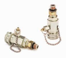
Eaton’s FD15 Series Oil Sampling Valve is designed for in-line sampling of system fluids without system shutdown, usually in less than one minute, and without fluid contamination.
Product Features
• Standard seal material: Buna-N
• Corrosion resistant plated steel with brass internal components
• Operating Temperature Range: –65°F to +275°F (–53°C to +135°C)
• Minimum Burst Pressure: 12,000 psi
• Minimum Particle Restriction: 500 microns
• Maximum Torque to Operate: 10 in. lbs.
• FD15-1000-04 is qualified to the MIL-V-81940/2-1
Note: This valve is not intended for aerospace applications.
Applications & Markets
• Engine oil
• Lubricating oil
• Transmission fluid and hydraulic fluids in mobile construction equipment, military vehicles, trucks and stationary equipment
Operation
• For best results, Eaton FD15 Oil Sampling Valves should be installed in dynamic fluid lines in low pressure and return lines. If only one sampling point can be chosen, it should be in the return line, upstream of any return line filter. This will insure a representative sample of all components in the fluid system for their present condition.
Instructions
1. Remove metal dustcover on discharge port.
2. Discharge approximately 200 ml of oil to flush valve by turning knurled knob 1/4 turn to the right. Dispose of this sample in the appropriate manner.
3. Locate clean oil sample bottle under discharge port. (Sample bottles are usually supplied by the oil analysis lab.)
4. Turn knurled knob 1/4 turn to the right until bottle is filled to the desired level. The knob can be backed off to throttle the rate of flow.
5. When bottle is filled let go of the knurled knob, the valve will close automatically. Replace metal dustcover wrench tight.
Notes
As required in MIL-V81940/2-1 this valve’s flow rate is between 100 and 1500 milliliters per minute at pressures from 0–50 psi. (MIL-V-81940/2-1 applies only to pressures from 50–300 psi.)
The 1/4” NPTF version is qualified to MIL-V-81940/21 and its performance is representative of the other inlet port configurations listed above. QPL-81940-9
6-5-89
134 FLUID TRANSFER AND HYDRAULIC PNEUMATIC SPECIAL APPLICATIONS DIAGNOSTIC AGRICULTURE REFRIGERANT EATON Quick Disconnect Couplings Master Catalog E-MEQD-CC001-E8 August 2017
Page 134
FD15 Series Oil Sampling Valve

Male Pipe Thread 50-300 psi

Male SAE O-Ring Thread 50-300 psi
(Male Pipe Thread)
(Male SAE O-Ring Thread)
(Male Pipe Thread)
Male SAE O-Ring Thread)
135 PNEUMATIC SPECIAL APPLICATIONS DIAGNOSTIC AGRICULTURE REFRIGERANT FLUID TRANSFER AND HYDRAULIC EATON Quick Disconnect Couplings Master Catalog E-MEQD-CC001-E8 August 2017 Dimensions
Part Number Sampling Port Dimensions Buna-N Type Size Thread Type Fig. A B C Hex 1 Hex 2 Hex 3 mm (in) mm (in) mm (in) mm (in) mm (in) mm (in) FD15-1000-02 50-300 psi 1/8 1/8-27 Male Pipe Thread 1 61.5 (2.42) 25.4 (1.00) 33.0 (1.30) 17.5 (.69) 9.7 (.38) -FD15-1000-04 50-300 psi 1/4 1/4-18 Male Pipe Thread 1 65.0 (2.56) 25.4 (1.00) 33.0 (1.30) 17.5 (.69) 9.7 (.38) -Dimensions
Part Number Sampling Port Dimensions Buna-N Type Size Thread Type Fig. A B C Hex 1 Hex 2 Hex 3 mm (in) mm (in) mm (in) mm (in) mm (in) mm (in) FD15-1002-04 50-300 psi 7/16 7/16-20 Male SAE O-Ring Thread 2 70.9 (2.79) 25.4 (1.00) 33.0 (1.30) 17.5 (.69) 9.7 (.38) 14.2 (.56) Dimensions
Part Number Sampling Port Dimensions Buna-N Type Size Thread Type Fig. A B C Hex 1 Hex 2 Hex 3 mm (in) mm (in) mm (in) mm (in) mm (in) mm (in) FD15-1026-04 0-50 psi 1/4 1/4-18 Male Pipe Thread 3 65.0 (2.56) 25.4 (1.00) 33.0 (1.30) 17.5 (.69) 9.7 (.38) -Dimensions
Part Number Sampling Port Dimensions Buna-N Type Size Thread Type Fig. A B C Hex 1 Hex 2 Hex 3 mm (in) mm (in) mm (in) mm (in) mm (in) mm (in) FD15-1025-04 0-50 psi 7/16 7/16-20 Male SAE O-Ring Thread 4 70.9 (2.79) 25.4 (1.00) 33.0 (1.30) 17.5 (.69) 9.7 (.38) 14.2 (.56)
Figure 1
Male Pipe Thread 0-50 psi Male SAE O-Ring Thread 0-50 psi
Figure 2
Figure 3
Figure 4
Page 135
FD90 Series
Diagnostic Coupling
SAE J1502 Interchange
Eaton’s FD90 Series diagnostic coupling is designed to connect and disconnect pressure gauges to hydraulic systems, eliminating the need for permanent gauges. The maximum operating pressure is 7,000 psi.
Product Features
• Automatic sleeve for one hand push-to-connect operation
• Flush face valving provides minimal fluid loss and low air inclusion
• Self-sealing valve design


Physical Characteristics
allows connection and disconnection at 500 psi
• Broad range of end configurations for system accessibility
• Standard seal material:
Dimensions (Female Pipe, Valved)
Buna-N
• Standard seal material: High resistance carbon steel with zinc trivalent plating
Applications & Markets
• Diagnostic pressure testing for hydraulic systems
Dimensions (Male SAE O-Ring, Valved)
Dimensions (Male Pipe, Valved)

136 FLUID TRANSFER AND HYDRAULIC PNEUMATIC SPECIAL APPLICATIONS DIAGNOSTIC AGRICULTURE REFRIGERANT EATON Quick Disconnect Couplings Master Catalog E-MEQD-CC001-E8 August 2017
Figure 2
Coupling Max. Operating Min. Burst Pressure Vacuum Rated Air Fluid Body Size Pressure Connected Connected Only Flow Inclusion Loss (in) (bar) (psi) (bar) (psi) (in./Hg) (lpm) (gpm) cc. max. cc.max. 1/4 483 7,0 00 1,931 28,0 00 28 1.89 0.6 0.02 0.10
Part Number Part Number with Dust Cap Coupling Body Port Dimensions Buna-N Buna-N Type Size Size Thread Type Fig. A B Hex 1 mm (in) mm (in) mm (in) FD90-1034-02-04 FD90-1035-02-04 Plug/Male 1/4 1/8 1/8 - 27 Female NPT 1 43.2 (1.70) - - 15.7 (0.62) FD90-1021-02-04 Socket/Female 1/4 1/8 1/8 - 27 Female NPT 2 49.5 (1.95) 25.4 (1.00) 19.1 (0.75) FD90-1034-04-04 FD90-1035-04-04 Plug/Male 1/4 1/4 1/4 - 18 Female NPT 1 48.3 (1.90) - - 19.1 (0.75) FD90-1021-04-04 Socket/Female 1/4 1/4 1/4 - 18 Female NPT 2 57.2 (2.25) 25.4 (1.00) 19.1 (0.75)
Part Number Part Number with Dust Cap Coupling Body Port Dimensions Buna-N Buna-N Type Size Size Thread Type Fig. A B Hex 1 mm (in) mm (in) mm (in) FD90-1044-03-04 FD90-1004-03-04 Plug/Male 1/4 3/8 3/8 - 24 Male SAE O-Ring 3 38.6 (1.52) - - 15.7 (0.62) FD90-1044-04-04 FD90-1004-04-04 Plug/Male 1/4 7/16 7/16 - 20 Male SAE O-Ring 3 40.1 (1.58) - - 15.7 (0.62) FD90-1044-05-04 FD90-1004-05-04 Plug/Male 1/4 1/2 1/2 - 20 Male SAE O-Ring 3 33.5 (1.32) - - 15.7 (0.62) FD90-1044-06-04 FD90-1004-06-04 Plug/Male 1/4 9/16 9/16 - 18 Male SAE O-Ring 3 33.5 (1.32) - - 17.5 (0.69)
Part Number Part Number with Dust Cap Coupling Body Port Dimensions Buna-N Buna-N Type Size Size Thread Type Fig. A B Hex 1 mm (in) mm (in) mm (in) FD90-1012-02-04 FD90-1045-02-04 Plug/Male 1/4 1/8 1/8 - 27 Male NPT 4 40.6 (1.60) - - 15.7 (0.62) FD90-1012-04-04 FD90-1045-04-04 Plug/Male 1/4 1/4 1/4 - 18 Male NPT 4 37.8 (1.49) - - 17.5 (0.69)
Figur e 3
Figure 1
Figure 4
Page 136
FD90 Series
Diagnostic Coupling
SAE J1502 Interchange
Dimensions (Metric Male O-Ring, Valved)

Dimensions (Female SAE O-Ring, Valved)

Dimensions (Male ORS Bulkhead, Valved)
(Male ORS Bulkhead, Valved)
Dimensions (Male Metric O-Ring, Valved)
Dust
137 PNEUMATIC SPECIAL APPLICATIONS DIAGNOSTIC AGRICULTURE REFRIGERANT FLUID TRANSFER AND HYDRAULIC EATON Quick Disconnect Couplings Master Catalog E-MEQD-CC001-E8 August 2017
Part Number Part Number with Dust Cap Coupling Body Port Dimensions Buna-N Buna-N Type Size Size Thread Type Fig. A B Hex 1 mm (in) mm (in) mm (in) FD90-1046-06-04 FD90-1047-06-04 Plug/Male 1/4 M14 M14x1.5 Male O-Ring 5 38.5 (1.52) - - 19.1 (0.75)
Part Number Coupling Body Port Dimensions Buna-N Type Size Size Thread Type Fig. A B Hex 1 mm (in) mm (in) mm (in) FD90-1041-04-04 Socket/Female 1/4 7/16 7/16 - 20 Female SAE O-Ring 2 55.9 (2.20) 25.40 (1.0 0) 19.1 (0.75)
Part Number Coupling Body Port Dimensions Buna-N Type Size Size Thread Type Fig. A B Hex 1 mm (in) mm (in) mm (in) FD90-1206-04-04 Plug/Male 1/4 9/16 9/16 - 18 Male ORS Bulkhead 6 62.5 (2.46) 20.6 (0.81) 20.6 (0.81) Dimensions
Part Number Coupling Body Port Dimensions Buna-N Type Size Size Thread Type Fig. A B Hex 1 mm (in) mm (in) mm (in) FD90-1061-04-04 Plug/Male 1/4 9/16 9/16 - 18 Female ORS Swivel 7 46.5 (1.79) 22.1 (0.87) 17.5 (0.69) FD90-1061-06-04 Plug/Male 1/4 11/16 11/16 - 16 Female ORS Swivel 7 46.5 (1.83) 23.9 (0.94) 20.6 (0.81) FD90-1061-08-04 Plug/Male 1/4 13/16 13/16 - 16 Female ORS Swivel 7 49.0 (1.93) 27.4 (1.08) 23.9 (0.94)
Part Number Coupling Body Port Dimensions Buna-N Type Size Size Thread Type Fig. A B Hex 1 mm (in) mm (in) mm (in) FD90-1090-10-04 Plug/Male 1/4 M10 M10x1 Mertic O-Ring 8 40.1 (1.58) 18.3 (0.72)
Body Size Part Number 1/4 FD90-1040-04
Cap for Plug/Male Halves
Figure 6
Figure 8
Figure 7
Dust Cap for Plug/Male Halves
Page 137
Figure 5
Pressure Gauge Kit FF14802
Eaton’s Pressure Gauge Kit and screw together test couplings provide accurate and efficient pressure control and monitoring of your hydraulic system, while minimizing the introduction of contamination. The complete kit is pre-packaged with Eaton’s most common adapters and test couplings.

Product Features
• Test system at working pressure
• 63 0 bar (9,000 psi) working pressure
• 34 5 bar (5,000 psi) connect under pressure
Couplings/Adapters
• Standard body material: Zinc Nickel Plated Steel
• Standard seal material: FKM
• 34 5 bar (5,000 psi) connect under pressure
• 63 0 bar (9,000 psi) working pressure
Pressure Gauge Kit
• Accurate pressure control and system monitoring
• Leak-free connection before piston valve opens
Hose Assemblies

• 63 0 bar (9,000 psi) working pressure
• 20 mm (.75”) bend radius
• Nominal Bore 2mm (.08”)
• Hose cover/core – PA 11/12
• Reinforcement –synthetic fiber
• Simple and fast screw together connections
• Self-locking caps
Applications & Markets
• Hydraulics and mineral based fluids
• Agricultural equipment
• Construction equipment
• On -Highway vehicles
• Industrial equipment
Gauges
• Polished Brass Casing
• Glycerine Filled
• Dual Scales
• Relief Valve
• Acrylic Lens
* Wh en the indicated part number is ordered, the bag quantity is the number of pieces supplied. For example, if a quantity of one FF14792 is ordered, one bag containing two pieces will be delivered.
138 FLUID TRANSFER AND HYDRAULIC PNEUMATIC SPECIAL APPLICATIONS DIAGNOSTIC AGRICULTURE REFRIGERANT EATON Quick Disconnect Couplings Master Catalog E-MEQD-CC001-E8 August 2017
Complete Component Quantity Kit Number Part Number Description Per Kit FF14802 FF14783 1/8” NPT Test Coupling 2 FF14784 1/4” NPT Test Coupling 2 FF14787 7/16-20 UNF Test Coupling 1 FF14788 9/16-18 UNF Test Coupling 1 FF14794 1/4” NPT Gauge Adapter 3 Dimensions (Standard Test Couplings) Part Dimensions Bag Number Thread A B Hex 1 Quantity* mm (in) mm (in) mm (in) FF14783 1/8” NPT 45.0 (1.77) 20.0 (.79) 17.0 (.67) 4 FF14784 1/4” NPT 50.0 (1.97) 20.0 (.79) 17.0 (.67) 4 FF14785 M14 49.0 (1.93) 20.0 (.79) 19.0 (.75) 3 FF14786 M16 48.5 (1.91) 20.0 (.79) 22.0 (.87) 3 FF14787 7/16-20 UNF 47.0 (1.85) 20.0 (.79) 17.0 (.67) 4 FF14788 9/16-18 UNF 47.5 (1.87) 20.0 (.79) 19.0 (.75) 4 Complete Component Quantity Kit Number Part Number Description Per Kit FF14796 Union Adapter 2 FF14798 60” Test Hose Assembly 2 FF14799 (-) 30 in/Hg - 30 psi Gauge 1 FF14800 1,000 psi Gauge 1 FF14801 7,500 psi Gauge 1 B A 1 2 Standard Test Couplings
Page 138
(Bulkhead Couplings)

(Swivel Run Tee with Test Coupling)


(Gauge Adapter)

(Union Adapter)
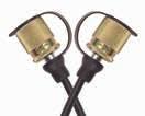
(Test Hose Assembly)
(Gauges)
139 PNEUMATIC SPECIAL APPLICATIONS DIAGNOSTIC AGRICULTURE REFRIGERANT FLUID TRANSFER AND HYDRAULIC EATON Quick Disconnect Couplings Master Catalog E-MEQD-CC001-E8 August 2017 A B T1 A B 1 2 1 2 1 A B T1 A B 1 2 T1 T2 Dimensions
Part Dimensions Bag Number Thread A B Hex 1 Hex 2 Quantity* mm (in) mm (in) mm (in) mm (in) FF14789 M16 72.0 2.83 20.0 .79 17.0 .67 19.0 .75 2 Dimensions
Part Dimensions Bag Number Thread #1 Thread #2 A B Hex 1 Quantity* mm (in) mm (in) mm (in) FF14790 7/16-20 UNF 7/16-20 UNF 47.7 (1.88) 20.0 (.79) 27.0 (1.06) 2 FF14791 9/16-18 UNF 9/16-18 UNF 47.7 (1.88) 20.0 (.79) 27.0 (1.06) 2 FF14792 3/4-16 UNF 3/4-16 UNF 47.7 (1.88) 20.0 (.79) 27.0 (1.06) 2 Dimensions
Part Dimensions Bag Number Thread #1 Thread #2 A Hex 1 Hex 2 Quantity* mm (in) mm (in) mm (in) FF14793 1/4” NPT M16 54.0 (2.13) 19.0 (.75) 19.0 (.75) 2 Dimensions
Part Dimensions Bag Number Thread A B Hex 1 Quantity* mm (in) mm (in) mm (in) FF14794 1/4” NPT 40.5 (1.59) 20.0 (.79) 19.0 (.75) 2 FF14795 7/16-20 UNF 41.0 (1.61) 20.0 (.79) 19.0 (.75) 2 Dimensions
Part Dimensions Bag Number Thread #1 Thread #2 A Hex 1 Quantity* mm (in) mm (in) FF14796 M16 M16 42.5 (1.67) 17.0 (.67) 2 Dimensions
Dimensions Part Cut Overall Bag Number Thread Length Length Quantity* mm (in) mm (in) FF14797 M16 872.0 (34.33) 914.4 (36.00) 1 FF14798 M16 1482.0 (58.35) 1524.0 (60.0 0) 1 Dimensions
Part Dimensions Bag Number Thread A B Rating Quantity* mm (in) mm (in) FF14799 1/4” NPT 65.3 (2.57) 53.3 (2.10) (-)30 in/Hg - 30 psi 1 FF1480 0 1/4” NPT 65.3 (2.57) 53.3 (2.10) 0 - 1,00 0 psi 1 FF14801 1/4” NPT 65.3 (2.57) 53.3 (2.10) 0 - 7,50 0 psi 1 Bulkhead Couplings Gauge Adapter Test Hose Assembly Gauges 1 2 1 2 A T1 T2 Swivel Run Tee with Test Coupling 1 2 T1 A T2 Union Adapter Direct Gauge Adapter Page 139
(Direct Gauge Adapter)
FD48 Series
Parker Bruning SM-250 Interchange
Eaton’s FD48 Series coupling is poppet style quick disconnect coupling designed to interchange with Parker Bruning SM-250 couplings where excellent high and low pressure sealing is required. The FD48 operates with pressures up to 3,000 psi.

Product Features
• Self-sealing poppet valves provide excellent high and low pressure sealing


• PUSH-PULL™ ball latch design allows quick and easy connection and disconnection of fluid lines Physical
• Heat-treated and plated steel for wear and corrosion resistance
• Standard seal material: Buna-N
• Standard seal material: High resistance carbon steel with zinc trivalent plating
Applications & Markets
• Hydraulic and fluid transfer
• Agricultural equipment
Dimensions (Female NPT, Valved)

140 FLUID TRANSFER AND HYDRAULIC PNEUMATIC SPECIAL APPLICATIONS DIAGNOSTIC AGRICULTURE REFRIGERANT EATON Quick Disconnect Couplings Master Catalog E-MEQD-CC001-E8 August 2017 4 5 6 7 8 9 10 12 14 16 18 20 30 40 0.05 0.1 0.5 1 2 3 4 bar lpm 1.056 2.64 5.28 7.92 10.56 0.725 1.45 7.25 14.5 29 43.5 58 gpm psi Flow Data Pressure Drop Versus Flow Graph Gallons Per Minute Flow Test Fluid: MIL-H-5606 Oil at 100°F Pressure Drop, bar
Characteristics Body Max. Operating Min. Burst Pressure Vacuum Rated Air Fluid Size Pressure Connected Connected Only Flow Inclusion Loss (in) (bar) (psi) (bar) (psi) (in./Hg) (lpm) (gpm) cc. max. cc.max. 1/4 210 3,00 0 840 12,0 00 28 11 3 .50 1.10
Part Number Coupling Body Port Dimensions Buna-N Type Size Size Thread Type Fig. A B Hex 1 mm (in) mm (in) mm (in) FD48-1002-04-04 Plug/Male 1/4 1/4 1/4-18 Female NPT 1 36.8 (1.45) - - 19.0 (.75) FD48-10 01-04-04 Socket/Female 1/4 1/4 1/4-18 Female NPT 2 51.1 (2.01) 26.9 (1.06) 20.6 (.81)
Figure 1
1/4 Dust Cap/Plug Part Number Body (Buna-N) Size FD48-1042-04* 1/4 *Fits both plug/male and socket/female halves Dust Cap/Plug Page 140
Figure 2
FD72/FD76 Series
Connect Under Pressure — Farm ISO 5675 Interchange
Eaton’s FD72 Series coupling incorporates special valving allowing connection to a FD76 Series male half under pressure. The maximum operating pressure is 3,000 psi. Contains an over travel, selfsealing poppet valve construction for connecting to a pressurized male tip. Applications require that the tractor control valve be actuated to open the flow path and to equalize the pressure.


Product Features
• Push-to-connect for onehand operation when sleeve is mounted
• Interchanges with ISO 5675 plug/male tips

Physical Characteristics
• Retaining ring groove on socket/female half for bulkhead and breakaway frame mounting


• Standard seal material: Buna-N
• Standard body material: High resistance carbon steel with zinc trivalent plating

Applications & Markets
•
•
Dimensions (Female NPT, Valved)
141 PNEUMATIC SPECIAL APPLICATIONS DIAGNOSTIC AGRICULTURE REFRIGERANT FLUID TRANSFER AND HYDRAULIC EATON Quick Disconnect Couplings Master Catalog E-MEQD-CC001-E8 August 2017
Figure 3
Body Max. Operating Min. Burst Pressure Vacuum Rated Air Fluid Size Pressure Connected Connected Only Flow Inclusion Loss (in) (bar) (psi) (bar) (psi) (in./Hg) (lpm) (gpm) cc. max. cc.max. 5/8 207 3,00 0 827 12,000 28 61 16 2.8 2.8
Part Number Coupling Body Port Dimensions Buna-N Type Size Size Thread Type Fig. A B C D E Hex 1 mm (in) mm (in) mm (in) mm (in) mm (in) mm (in) FD76-1002-08-10 Plug/Male 5/8 1/2 1/2-14 Female Pipe 1 52.1 (2.05) 26.9 (1.06) FD72-1001-08-10 Socket/Female 5/8 1/2 1/2-14 Female Pipe 2 80.5 (3.17) 38.6 (1.52) 38.1 (1.50) 35.8 (1.41) 5.1 (.20) 25.4 (1.00) FD76-1010-08-10 Plug/Male 5/8 1/2 3/4-16 Female SAE O-Ring 3 52.1 (2.05) 27.0 (1.06)
Dust Cap Part Number Body Buna-N Size 5657-10 5/8 Dust Plug Part Number Body Buna-N Size 5659-10 5/8 Break Away Frame Part Number Body Buna-N Size 5603 5/8 Break Away Frame Dust Cap Dust Plug
Figure 1
Flow Data Pressure Drop Versus Flow Graph Gallons Per Minute Flow Test Fluid: MIL-H-5606 Oil at 100°F Pressure Drop, bar 4 5 6 7 8 9 10 12 14 16 18 20 30 40 60 80 0.05 0.1 0.2 0.3 0.4 0.5 1 2 3 4 bar lpm 1.06 2.64 5.28 7.92 10.56 15.8 21.1 0.725 1.45 2.9 4.35 5.8 7.25 14.5 29 43.5 58 gpm psi 5/8
Figure 2
Hydraulic fluid transfer
Agricultural equipment Page 141
5400 Series Low Air Inclusion Refrigerant
Eaton’s 5400 Series low air inclusion product line is designed for air conditioning, refrigerant, gaseous and fluid transfer applications.

Product Features
• Brazed or threaded end connections for versatility of installation on tubing or hose

• Tubular valve construction for low fluid loss and air inclusion
• Thread together design allows connection and disconnection against pressure
• Lock washer and jam nut standard for optional bulkhead mounting
• Standard seal material: Neoprene
• Guardian Seal™ plating for excellent corrosion resistance
Applications & Markets
• Mobile air conditioning and refrigerant
142 FLUID TRANSFER AND HYDRAULIC PNEUMATIC SPECIAL APPLICATIONS DIAGNOSTIC AGRICULTURE REFRIGERANT EATON Quick Disconnect Couplings Master Catalog E-MEQD-CC001-E8 August 2017
Physical Characteristics Max. Operating Pressure Vacuum Coupling Max. Operating Pressure Min. Burst Pressure Disconnected Connected Rated Air Fluid Size Connected Connected Male Half Female Half Only Flow Inclusion Loss (in) (bar) (psi) (bar) (psi) (bar) (psi) (bar) (psi) (in./Hg) (lpm) (gpm) cc. max. cc.max. 1/4 207 3,000 621 9,000 172 2,500 34 500 28 8 2 .10 .05 1/2 121 1,750 359 5,200 121 1,750 28 400 28 53 14 .10 .10 3/4 48 700 145 2,100 55 800 28 400 28 132 35 .30 .10 1 48 700 145 2,100 48 700 21 300 28 284 75 .50 .20
Flow Data
Drop, bar Page 142
Pressure
5400 Series
Low Air Inclusion Refrigerant


– No Adapter
Dimensions – SAE 37° (JIC)


143 PNEUMATIC SPECIAL APPLICATIONS DIAGNOSTIC AGRICULTURE REFRIGERANT FLUID TRANSFER AND HYDRAULIC EATON Quick Disconnect Couplings Master Catalog E-MEQD-CC001-E8 August 2017
Figure 2
Figure 3
Figure 1
Figure 4
Figure 6
Figure 7
Dimensions
Part Number Coupling Body Dimensions Neoprene Type Size Type Fig. A B Hex 1 Hex 2 Hex 3 mm (in) mm (in) mm (in) mm (in) mm (in) 5400-S2-4 Male 1/4 No Adapter 1 27.4 (1.08) 21.1 (.83) 19.1 (.75) - - -5400-S5-4 Female 1/4 No Adapter 2 28.7 (1.13) 21.1 (.83) 16.0 (.63) 19.1 (.75) -5400-S2-8 Male 1/2 No Adapter 1 34.8 (1.37) 32.0 (1.26) 29.0 (1.14) - - -5400-S5-8 Female 1/2 No Adapter 2 40.6 (1.60) 33.0 (1.30) 26.0 (1.02) 30.0 (1.18) -5400-S2-12 Male 3/4 No Adapter 1 44.2 (1.74) 46.4 (1.83) 41.0 (1.64) - - -540 0-S5-12 Female 3/4 No Adapter 2 55.1 (2.17) 45.0 (1.77) 35.0 (1.38) 41.0 (1.61) -5400-S2-16 Male 1 No Adapter 1 46.5 (1.83) 53.0 (2.10) 48.0 (1.89) - - -5400-S5-16 Female 1 No Adapter 2 61.1 (2.41) 56.0 (2.20) 45.0 (1.77) 50.0 (1.97) - -
Figure 5
Part Number Coupling Body Port Dimensions Buna-N Type Size Size Thread Type Fig. A B Hex 1 Hex 2 Hex 3 *Couplings must be ordered by components as shown on page 150. mm (in) mm (in) mm (in) mm (in) mm (in) 5410-S17-4-4* Male 1/4 7/16 7/16-20 SAE 37° (JIC) 3 47.8 (1.88) 21.1 (.83) 19.1 (.75) - - 16.0 (.63) 5410-S14-4-4* Female 1/4 7/16 7/16-20 SAE 37° (JIC) 4 49.0 (1.93) 21.1 (.83) 16.0 (.63) 19.1 (.75) 15.7 (.62) 5410-4-4* Complete 1/4 7/16 7/16-20 SAE 37° (JIC) 5 89.9 (3.54) - - - - - - -5410-S17-6-4* Male 1/4 9/16 9/16-18 SAE 37° (JIC) 3 48.0 (1.89) 21.1 (.83) 19.1 (.75) - - 16.0 (.63) 5410-S14-6-4* Female 1/4 9/16 9/16-18 SAE 37° (JIC) 4 49.3 (1.94) 21.1 (.83) 16.0 (.63) 19.1 (.75) 15.7 (.62) 5410-6-4* Complete 1/4 9/16 9/16-18 SAE 37° (JIC) 5 90.4 (3.56) - - - - - - -5410-S17-6-8* Male 1/2 9/16 9/16-18 SAE 37° (JIC) 3 55.4 (2.18) 31.8 (1.25) 28.7 (1.13) - - 25.4 (1.00) 5410-S14-6-8* Female 1/2 9/16 9/16-18 SAE 37° (JIC) 4 61.7 (2.43) 33.3 (1.31) 25.4 (1.00) 30.2 (1.19) 25.4 (1.00) 5410-6-8* Complete 1/2 9/16 9/16-18 SAE 37° (JIC) 5 107.4 (4.23) - - - - - - -5410-S17-8-8* Male 1/2 3/4 3/4-16 SAE 37° (JIC) 3 57.9 (2.28) 31.8 (1.25) 28.7 (1.13) - - 25.4 (1.00) 5410-S14-8-8* Female 1/2 3/4 3/4-16 SAE 37° (JIC) 4 64.3 (2.53) 33.3 (1.31) 25.4 (1.00) 30.2 (1.19) 25.4 (1.00) 5410-8-8* Complete 1/2 3/4 3/4-16 SAE 37° (JIC) 5 112.8 (4.44) - - - - - - -5410-S17-10-12* Male 3/4 7/8 7/8-14 SAE 37° (JIC) 3 69.9 (2.75) 46.5 (1.83) 41.4 (1.63) - - 35.1 (1.38) 5410-S14-10-12* Female 3/4 7/8 7/8-14 SAE 37° (JIC) 4 80.3 (3.16) 45.7 (1.80) 35.1 (1.38) 41.1 (1.62) 35.1 (1.38) 5410-10-12* Complete 3/4 7/8 7/8-14 SAE 37° (JIC) 5 135.4 (5.33) - - - - - - -5410-S17-12-12* Male 3/4 1 1/16 1 1/16-12 SAE 37° (JIC) 3 72.6 (2.86) 46.5 (1.83) 41.4 (1.63) - - 35.1 (1.38) 5410-S14-12-12* Female 3/4 1 1/16 1 1/16-12 SAE 37° (JIC) 4 83.1 (3.27) 45.7 (1.80) 35.1 (1.38) 41.1 (1.62) 35.1 (1.38) 5410-12-12* Complete 3/4 1 1/16 1 1/16-12 SAE 37° (JIC) 5 140.7 (5.54) - - - - - - -5410-S17-16-16* Male 1 1 5/16 1 5/16-12 SAE 37° (JIC) 3 75.9 (2.99) 53.3 (2.10) 47.8 (1.88) - - 44.5 (1.75) 5410-S14-16-16* Female 1 1 5/16 1 5/16-12 SAE 37° (JIC) 4 89.7 (3.53) 56.9 (2.24) 44.5 (1.75) 50.8 (2.00) 44.5 (1.75) 5410-16-16* Complete 1 1 5/16 1 5/16-12 SAE 37° (JIC) 5 149.6 (5.89) - - - - - - -Page 143
5400 Series
Low Air Inclusion Refrigerant
– Braze Tubing Adapter


Hose Fitting SAE 100R5†


144 FLUID TRANSFER AND HYDRAULIC PNEUMATIC SPECIAL APPLICATIONS DIAGNOSTIC AGRICULTURE REFRIGERANT EATON Quick Disconnect Couplings Master Catalog E-MEQD-CC001-E8 August 2017
Dimensions
Part Number Coupling Body Tube O.D. Dimensions Neoprene Type Size Size Type Fig. A B Hex 1 Hex 2 Hex 3 *Couplings must be ordered by components as shown on page 150. mm (in) mm (in) mm (in) mm (in) mm (in) 5401-S17-4-4* Male 1/4 1/4 Braze Tubing Adapter 6 38.6 (1.52) 21.1 (.83) 19.1 (.75) - - 16.0 (.63) 5401-S14-4-4* Female 1/4 1/4 Braze Tubing Adapter 7 39.9 (1.57) 21.1 (.83) 16.0 (.63) 19.1 (.75) 16.0 (.63) 5401-S17-6-4* Male 1/4 3/8 Braze Tubing Adapter 6 38.6 (1.52) 21.1 (.83) 19.1 (.75) - - 16.0 (.63) 5401-S14-6-4* Female 1/4 3/8 Braze Tubing Adapter 7 39.9 (1.57) 21.1 (.83) 16.0 (.63) 19.1 (.75) 16.0 (.63) 5410-S17-6-8* Male 1/2 3/8 Braze Tubing Adapter 6 44.5 (1.75) 33.3 (1.31) 28.7 (1.13) - - 25.4 (1.00) 5401-S14-6-8* Female 1/2 3/8 Braze Tubing Adapter 7 50.8 (2.00) 33.3 (1.31) 25.4 (1.00) 30.2 (1.19) 25.4 (1.00) 5401-S17-8-8* Male 1/2 1/2 Braze Tubing Adapter 6 44.5 (1.75) 33.3 (1.31) 28.7 (1.13) - - 25.4 (1.00) 5401-S14-8-8* Female 1/2 1/2 Braze Tubing Adapter 7 50.8 (2.00) 33.3 (1.31) 25.4 (1.00) 30.2 (1.19) 25.4 (1.00) 5401-S17-10-12* Male 3/4 5/8 Braze Tubing Adapter 6 62.7 (2.47) 45.7 (1.80) 41.4 (1.63) - - 35.1 (1.38) 5401-S14-10-12* Female 3/4 5/8 Braze Tubing Adapter 7 73.2 (2.88) 45.7 (1.80) 35.1 (1.38) 41.4 (1.63) 35.1 (1.38) 5401-S17-12-12* Male 3/4 3/4 Braze Tubing Adapter 6 62.7 (2.47) 45.7 (1.80) 41.4 (1.63) - - 35.1 (1.38) 5401-S14-12-12* Female 3/4 3/4 Braze Tubing Adapter 7 73.2 (2.88) 45.7 (1.80) 35.1 (1.38) 41.4 (1.63) 35.1 (1.38) 5401-S17-16-16* Male 1 1 Braze Tubing Adapter 6 71.1 (2.80) 56.9 (2.24) 47.8 (1.88) - - 44.5 (1.75) 5401-S14-16-16* Female 1 1 Braze Tubing Adapter 7 84.8 (3.34) 56.9 (2.24) 44.5 (1.75) 50.8 (2.00) 44.5 (1.75)
Dust Cap with Gasket Dust Plug with Gasket Body Size 5400-S6-4 5400-S8-4 1/4 5400-S6-8 540 0-S8-8 -1/2 5400-S6-12 540 0-S8-12 3/4 5400-S6-16 540 0-S8-16 1 Adapter SAE 37° (JIC) O-Ring Brass Steel Body Size Thread Tube O.D. Size 22546-12 202220-4-4B 202220-4-4S 1/4 7/16-20 1/4 22546-12 202220-6-4B 202220-6-4S 1/4 9/16-18 3/8 22546-17 - 202220-6-8S 1/2 9/16-18 3/8 22546-17 202220-8-8B 202220-8-8S 1/2 3/4-16 1/2 22546-23 - 202220-10-12S 3/4 7/8-14 5/8 22546-23 - 202220-12-12S 3/4 1 1/16-12 3/4 22546-28 - 202220-16-16S 3/4 1 3/16-12 1 Adapter – Braze O-Ring Brass Steel Body Size Thread Tube O.D. Size 22546-12 202208-4-4B - 1/4 1/2-20 1/4 22546-17 202208-4-8B - 1/2 7/8-20 1/4 22546-12 202208-6-4B - 1/4 1/2-20 3/8 22546-17 202208-6-8B - 1/2 7/8-20 3/8 22546-17 202208-8-8B - 1/2 7/8-20 1/2 2254617 202208-10-8B 202208-10-8S 1/2 7/8-20 5/8 22546-23 202208-10-12B 202208-10-12S 3/4 1 1/4-18 5/8 22546-23 202208-12-12B - 3/4 1 1/4-18 3/4 22546-23 202208-14-12B - 3/4 1 1/4-18 7/8 22546-28 202208-14-16B - 1 1 19/32-20 7/8 22546-28 202208-16-16B - 1 1 19/32-20 1 22546-28 202208-18-16B - 1 1 19/32-20 1 1/8 22546-28 202208-20-16B - 1 1 19/32-20 1 3/16 22546-28 202208-22-16B - 1 1 19/32-20 1 1/4
Dust Caps and Dust Plugs
Dimensions O-Ring Fitting Assembly Body Size Hose Size Thread D mm (in) 22546-12 487-4-4S 1/4 -4 1/2-20 23.4 (.92) 22546-12 487-4-6S 1/4 -6 1/2-20 24.4 (.96) 22546-17 487-8-6S 1/2 -6 7/8-20 24.4 (.96) 22546-17 487-8-8S 1/2 -8 7/8-20 26.9 (1.06) 22546-23 487-12-10S 3/4 -10 1 1/4-18 27.2 (1.07) 22546-23 487-12-12S 3/4 -12 1 1/4-18 27.2 (1.07) 22546-28 487-16-16S 1 -16 1 19/32-20 25.7 (1.01) †Additional dash styles available. Dust Cap Dust Plug Adapter SAE 37° (JIC) Adapter – Braze (O-Ring Required) Hose Fitting SAE 100R5 (O-Ring Required) Page 144
5400 Series
Low Air Inclusion Refrigerant
For assemblies, order by components as shown by base number and dash (-) size below. Example, if a 5401-S14-10-12 is required, order as components, (1) 5400-S5-12, (1) 202208-10-12B Adapter and (1) 22546-23 O-Ring.
145 PNEUMATIC SPECIAL APPLICATIONS DIAGNOSTIC AGRICULTURE REFRIGERANT FLUID TRANSFER AND HYDRAULIC EATON Quick Disconnect Couplings Master Catalog E-MEQD-CC001-E8 August 2017
Assembly 5400-S2 5400-S5 202208-Brass 202220-Steel Part Male Female Braze-On 37˚ SAE 22546 Number Half Quantity Half Quantity Adapter Quantity Adapter Quantity O-Ring Quantity 5401-S14-10-12 -12 1 -10 -12B 1 -23 1 5401-S14-10-8 -8 1 -10 -8B -17 1 5401-S14-12-12 -12 1 -12 -12B 1 -23 1 5401-S14-16-16 -16 1 -16 -16B 1 -28 1 5401-S14-4-4 -4 1 -4 -4B 1 -12 1 5401-S14-6-4 -4 1 -6 -4B 1 -12 1 5401-S14-6-8 -8 1 -6 -8B 1 -17 1 5401-S14-8-8 -8 1 -8 -8B 1 -17 1 5401-S17-10-12 -12 1 -10 -12B 1 -23 1 5401-S17-10-8 -8 1 -10 -8B 1 -17 1 5401-S17-12-12 -12 1 -12 -12 1 -23 1 5401-S17-14-16 -16 1 -16 -16 1 -28 1 5401-S17-4-4 -4 1 -4 -4B 1 -17 1 5401-S17-6-4 -4 1 -6 -4B 1 -12 1 5401-S17-6-8 -8 1 -6 -8B 1 -17 1 5401-S17-8-8 -8 1 -8 -8B 1 -17 1 5410-12-12 -12 1 -12 1 -12 -12S 2 -23 2 5410-16-16 -16 1 -16 1 -16 -16S 2 -28 2 5410-4-4 -4 1 -4 1 -4 -4S 2 -12 2 5410-6-8 -8 1 -8 1 -6 -8S 2 -17 2 5410-8-8 -8 1 -8 1 -8 -8S 2 -17 2 5410-S14-10-12 -12 1 -10 -12S 1 -23 1 5410-S14-12-12 -12 1 -12 -12S 1 -23 1 5410-S14-16-16 -16 1 -16 -16S 1 -28 1 5410-S14-4-4 -4 1 -4 -4S 1 -12 1 5410-S14-6-4 -4 1 -6 -4S 1 -12 1 5410-S14-6-8 -8 1 -6 -8S 1 -17 1 5410-S14-8-8 -8 1 -8 -8S 1 -17 1 5410-S17-10-12 -12 1 -10 -12S 1 -23 1 5410-S17-12-12 -12 1 -12 -12S 1 -23 1 5410-S17-16-16 -16 1 -16 -16S 1 -28 1 5410-S17-4-4 -4 1 -4 -4S 1 -12 1 5410-S17-6-4 -4 1 -6 -4S 1 -12 1 5410-S17-6-8 -8 1 -6 -8S 1 -17 1 5410-S17-8-8 -8 1 -8 -8S 1 -17 1 Page 145
5400 Series
Low Air Inclusion Refrigerant
Assembly Instructions/Component Part Numbers
Typical Male Coupling Half (S2)
Assembly Instructions
Steps:
1. After tubing or hose has been connected to adapters 1 and 12 , install O-Rings 2 and 11 † on adapters. Be sure O-Rings are not twisted.
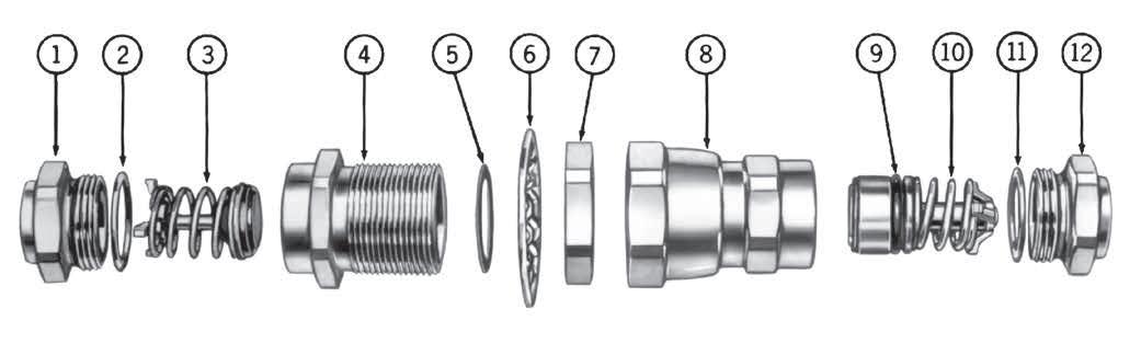
2. Oil O-Rings 2 and 11 liberally with system fluid to prevent them from scuffing and tearing when coupling body is threaded on adapter.
3. S2 Half—Lubricate poppet face with system fluid. Insert poppet valve assembly 3 into body 4 . Tighten body 4 on adapter 1 . After body and adapter make metal-to-metal contact, tighten by rotating body 4 1/8” with respect to adapter 1 or torque per table value.
S5 Half—Oil O-Ring 9 † liberally with system fluid. Inser t valve and sleeve assembly 10 into body 8 . Tighten body 8 on adapter 12 . After body and adapter make metal-tometal contact, tighten by rotating body 8 1/8” with respect to adapter 12 or torque per table value.
4. Coupling Connection—Lubricate gasket seal 5 on 5400-S2 half with system fluid. Thread union nut 8 on 5400-S2 half. Tighten union nut to torque values shown in table. Be sure S2 and S5 bodies do not rotate during connection.
Typical Female Coupling Half (S5)
Bulkhead Mounting—S2 Half
Install lock washer 6 on S2 half. Insert S2 half through bulkhead, and tighten jam nut 7 so that lock washer teeth are fully compressed.
NOTE: Lock washer 6 must be between hex of S2 half and bulkhead.
Maximum Bulkhead Thickness Body
Tubing size of adapter required in 16th of an inch. Example:
Torque Values
Recommended torque values in ft. lbs., are listed below. Adapter to Body
146 FLUID TRANSFER AND HYDRAULIC PNEUMATIC SPECIAL APPLICATIONS DIAGNOSTIC AGRICULTURE REFRIGERANT EATON Quick Disconnect Couplings Master Catalog E-MEQD-CC001-E8 August 2017
Component Part Numbers Item Da sh Sizeg –4 –8 –12 –16 Line Number O.D. Tube Sizeg 1/4”–3/8” 1/4”–5/8” 5/ 8”–7/8” 7/ 8”–13/8” Ref. Ty pical Male Half 1 1 Tubing Adapter 20 2208–*–4 20 2208–*–8 20 2208–*–12 20 2208–*–16 2 2 O- Ring 22546–12 22546–17 22546–23 22546–28 3 3 Poppet Valve Assembly 54 00–S20–4 54 00–S20–8 54 00–S20–12 54 00–S20–16 4 4 Body 54 00–17–4 54 00–17–8 54 00–17–12 54 00–17–16 5 5 Gasket Seal 22008–4 22008–8 22008–12 22008–16 6 6 Lock Washer 540 0–54–4S 540 0–54–8S 540 0–54–12S 540 0–54–16S 7 7 Jam Nut 54 00–53–4S 54 00–53–8S 54 00–53–12S 54 00–53–16S 8 Ty pical Female Half 9 8 Union Nut and Body Assembly 54 00–S16–4 54 00–S16–8 54 00–S16–12 54 00–S16–16 10 9 O- Ring FF 91178–10 FF 91178–112 FF 91178–116 22546–214 11 10 Valve and Sleeve Assembly 54 00–S19–4 54 00–S19–8 54 00–S19–12 54 00–S19–16 12 11 O- Ring 22546–12 22546–17 22546–23 2 2546–28 13 12 Tubing Adapter 20 2208–*–4 20 2208–*–8 20 2208–*–12 20 2208–*–16 14
–4
with 3/8” O.D. tubing is 6/16 or –6.
202208–6–4.
*Specify O.D.
coupling
Part number is then
Lock
Lock
Size Installed Not Used 1/4 .206 .256 1/2 136 .203 3/4 232 .2 92 1 101 .161
Washer
Washer
Braze Type Non-braze Type S2 Half Size or Aluminum Steel or Brass to S5 Half –4 6– 8 12–15 10 –12 –8 15–20 3 5–45 35– 37 –12 3 5–40 45– 55 45–47 –16 5 0–60 55 –65 65 –67 † IMPORTANT:
O-Rings.
Page 146
Dash
Generous lubrication is required for all gaskets and
Use refrigeration oil only when used in refrigerant system.
Part Number Index
147 EATON Quick Disconnect Couplings Master Catalog E-MEQD-CC001-E8 August 2017
Part Number Page Number 10 70, 78, 88 11 70, 78, 89 13 70, 78, 89 14 70, 78, 88 16 71, 79, 89 17 71, 79, 89 38 73, 81 40 73, 81, 106 41 73, 81, 107 42 73, 81, 106 43 73, 81, 107 44 73, 81, 106 52 75, 83, 106 53 75, 83, 107 55 75, 83, 107 56 75, 83, 106 57 75, 83, 107 59 76, 84, 107 60 76, 84, 107 101 94 103 94 104 95 105 94 180 93 183 93 186 93 187 93 189 93 210 109 310 110 400 73 404 73, 82, 107 406 73, 82, 107 408 73, 82, 107 410 73 420 73 430 73 440 73 450 73 500 75 501 75 510 75 520 75 540 75 550 75 570 76 580 76 Part Number Page Number 585 76, 84 590 76 900 70 1100 70 1200 70 1300 70 1800 71 2607 88, 109 2608 88, 109 2609 89, 109 2800 78 2900 78 3000 78 3200 78 3600 79 3800 79 3804 110 3806 110 3807 110 3946 89, 109 3947 89, 109 4000 81 4100 81 4200 81 4300 81 4400 81 5000 83 5200 83 5500 83 5603 22 5603 144 5900 84 6300 85 6500 86 6900 86 40600 82 40800 82 50100 83 50400 84 62210 109 100008 132 100010 132 100506 132 100508 132 100510 132 100512 132 210022 109 Page 147
Part Number Index
148 EATON Quick Disconnect Couplings Master Catalog E-MEQD-CC001-E8 August 2017
Part Number Page Number 210212 109 210213 109 210215 109 300043 78 310222 110 310313 110 530143 75 23203004 107 23203013 106 23203014 106 23203024 107 23203025 107 23203300 107 23204005 107 23204014 106 23204015 106 23204025 107 23204026 107 23204400 107 00A 97 01A 97 02A 97 03A 97 04R 97 05R 97 07A 98 08A 98 09A 98 100006E 132 100012E 132 1000E 70 100E 95 102E 95 10C 70, 78, 88 10FFP37 37 10FFP37BS 37 10FFP50 37 32FFP125 37 32FFP162UN 37 10FFP50BS 37 10FFP56ORM 38 10FFP56ORM143 38 10FFP56ORM192 38 10FFP56UN 37 10FFP75ORM 38 10FFP75ORM143 38 10FFP75ORM192 38 Part Number Page Number 10FFP75UN 37 10FFP87UN 37 10FFPCUP37 42 10FFPCUP37BS 42 10FFPCUP50 42 10FFPCUP50BS 42 12FFPCUP50 42 12FFPCUP50BS 42 12FFPCUP56UN 42 12FFPCUP75UN 42 10FFS37 35 10FFS37BS 35 10FFS50 35 10FFS50BS 35 10FFS56ORM 36 10FFS56UN 35 10FFS75ORM 36 10FFS75UN 35 10FFS87UN 35 32FFS125 35 32FFS125BS 35 32FFS162UN 35 10G 70, 78, 88 10H41 9 10H41BS 9 10K41 10 10K41BS 10 10NK 70, 78, 88 10S41 125 10S41BS 125 10T40 124 10T41 125 110E 95 111E 95 112E 95 11B 70, 78, 89 11G 70, 78, 89 11NK 70, 78, 89 12E 70, 78, 88 12FFP106UN 37 12FFP50 37 12FFP50BS 37 12FFP75 37 12FFP75BS 37 12FFP75UN 37 12FFP87UN 37 12FFS106UN 35 Page 148
Part Number Index
149 EATON Quick Disconnect Couplings Master Catalog E-MEQD-CC001-E8 August 2017
Part Number Page Number 12FFS50 35 12FFS50BS 35 12FFS75 35 12FFS75BS 35 12FFS75UN 35 12FFS87UN 35 12G 70, 78, 88 12H41 9 12H41BS 9 12H46 9 12H46BS 9 12K41 10 12K41BS 10 12K46 10 12K46BS 10 12S46 125 12S46BS 125 12T45 124 12T46 125 14G 70, 78, 88 150-22-12 50 150-22-16 50 150-22-20 50 150-22-5 50 150-22-8 50 15E 70, 78, 89 1600E 71 1600P 71 16FFP106UN 37 16FFP50 37 16FFP50BS 37 16FFP75 37 16FFP75BS 37 16FFP75UN 37 16FFP87UN 37 16FFS106UN 35 16FFS50 35 16FFS50BS 35 16FFS75 35 16FFS75BS 35 16FFS75UN 35 16FFS87UN 35 16G 71, 79, 89 16NK 71, 79, 89 16P 71, 79, 89 16S51 125 16S51BS 125 Part Number Page Number 16T50 124 16T51 125 1700E 71 1700P 71 17G 71, 79, 89 17NK 71, 79, 89 17P 71, 79, 89 185E 95 18E 71, 79, 89 19FFP100 37 19FFP100BS 37 19FFP106UN 37 19FFP131UN 37 19FFP75 37 19FFP75BS 37 19FFS100 35 19FFS100BS 35 19FFS106UN 35 19FFS131UN 35 19FFS75 35 19FFS75BS 35 1G1 94 1G10E 95 1G12E 95 1G2 95 1G3E 94 1G5E 94 1GB3 95 1GB7 95 1GD9 95 1H11 9 1H4 9 1K11 10 1K4 10 1S10 124 1S10BS 124 1S11 125 1S11BS 125 1S12 126 1S17 126 1SB1 72 1SB3 72 1SB5E 72 1SB7 72 1SC5 72 1SC7 72 1SC9 72 Page 149
Part Number Index
150 EATON Quick Disconnect Couplings Master Catalog E-MEQD-CC001-E8 August 2017
Part Number Page Number 1SD11 72 1SD5 72 1SD7 72 1SD9 72 1T10E 122 1T11 123 1T15 122 202208–*–12 146 202208–*–16 146 202208–*–4 146 202208–*–8 146 20AP37F 89, 110 20AP37M 88, 109 20H51 9 20H51BS 9 20H56 9 20H56BS 9 20H61 9 20H61BS 9 20K51 10 20K51BS 10 20K56 10 20K56BS 10 20K61 10 20K61BS 10 20S56 123 20T56 123 210B 109 21AP25F 89 21AP25H 89 21AP25M 88 22008–12 146 22008–16 146 22008–4 146 22008–8 146 22238E 89, 109 22239E 110 22546–12 146 22546–17 146 22546–214 146 22546–23 146 22546–28 146 24AP25FBS 90 24AP25FG 90 24AP25MBST 90 24AP50MBST 90 25FFP100 37 Part Number Page Number 25FFP100BS 37 25FFP125 37 25FFP125BS 37 25FFP131UN 37 25FFP162UN 37 40FFP150 37 40FFP150BS 37 40FFP187UN 37 50FFP200 37 50FFP200BS 37 50FFP250UN 37 25FFS100 35 25FFS100BS 35 25FFS125 35 25FFS125BS 35 25FFS131UN 35 25FFS162UN 35 40FFS150 40 40FFS150BS 40 40FFS187UN 35 50FFS200 40 50FFS200BS 40 50FFS250UN 35 2608B 88, 109 2609B 88, 109 28S12F 95 28S25M 95 2DBPG143 48 2DBPG242 48 2DBPG292 48 2DBPG503 48 2DBSG143 48 2DBSG242 48 2DBSG292 48 2DBSG503 48 2H16 9 2H16BS 9 2H6 9 2HIG10 119 2HIG11 119 2HIG15 119 2HIG16 119 2HIG20 119 2HIG720 119 2HIGLLRA720 119 2HIL10 120 2HIL11 120 Page 150
Part Number Index
151 EATON Quick Disconnect Couplings Master Catalog E-MEQD-CC001-E8 August 2017
Part Number Page Number 2HIL15 120 2HIL16 120 2HIL20 120 2HIL720 120 2HILLLRA720 120 2K16 10 2K16BS 10 2K6 10 2KIGF 119 2KIGF15 119 2KIGF16 119 2KIGF20 119 2KIGF720 119 2KILF 120 2KILF15 120 2KILF16 120 2KILF20 120 2KILF720 120 2L10 102 2L11 102 2L15 102 2L15G 102 2L16 102 2L16G 102 2L17 103 2L185C7 103 2L185C9 103 2L18B3 103 2L195 103 2L20 102 2L20G 102 2L21 102 2L22 103 2L23D11 103 2L23D13 103 2L23D5 103 2L23D7 103 2L23D9 103 2L25 102 2L26 102 2L27 103 2L28P13 103 2L28P15 103 2R10 102 2R11 102 2R15 102 2R16 102 Part Number Page Number 2R17 103 2R185C7 103 2R185C9 103 2R18B1 103 2R18B11 103 2R18B3 103 2R18B7 103 2R195 103 2R20 102 2R21 102 2R22 103 2R23D11 103 2R23D13 103 2R23D7 103 2R23D9 103 2R25 102 2R26 102 2R27 103 2R28P13 103 2R28P15 103 2S15 122 2S16 123 2S16BS 123 2S17 124 2T15 122 2T16 123 3100E 78 31AP25F 73 31AP25M 73 31AP37F 73 31AP37M 73 3300E 78 3600P 79 3700E 79 3700P 79 3H21 9 3H21BS 9 3H8 9 3K21 10 3K21BS 10 3K8 10 3L10 104 3L15 104 3L15G 104 3L16 104 3L16G 104 3L17 105 Page 151
Part Number Index
152 EATON Quick Disconnect Couplings Master Catalog E-MEQD-CC001-E8 August 2017
Part Number Page Number 3L17G 105 3L195 105 3L195G 105 3L20 104 3L20G 104 3L21 104 3L22 105 3L22G 105 3L23D11 105 3L23D7 105 3L23D9 105 3L25 104 3L25G 104 3L26 104 3L26G 104 3L27 105 3L27G 105 3L28P13 105 3L28P15 105 3L30 104 3L30G 104 3L31 104 3L32 105 3L32G 105 3L33R23 105 3L33R25 105 3PB1 72, 79 3PB11 72, 79 3PB3 72, 79 3PB5 72, 79 3PB7 72, 79 3PB9 72, 79 3PC5 72, 79 3PC7 72, 79 3PC9 72, 79 3PD11 72, 79 3PD5 72, 79 3PD7 72, 79 3PD9 72, 79 3R15 104 3R16 104 3R17 105 3R195 105 3R20 104 3R21 104 3R22 105 3R23D11 105 Part Number Page Number 3R23D7 105 3R23D9 105 3R25 104 3R26 104 3R27 105 3R28P13 105 3R28P15 105 3R28P17 105 3R30 104 3R31A 104 3R32 105 3R33R23 105 3R33R25 105 3S20 122 3S20BS 122 3S21 123 3S21BS 123 3S22 124 3SA0 79 3SB1 79 3SB3 79 3SB5 79 3SB7 79 3SB9 79 3SC5 79 3SC7 79 3SC9 79 3SD11 79 3SD5 79 3SD7 79 3SD9 79 3T20 122 3T21 123 4000A 82 4004E 74 4006E 74 4008E 74 40400E 81 40500E 81 4050E 74 40G 73, 80 40NK 73, 80 40SD11 75 40SD7 75 40SD9 75 40SP13 75 40SP15 75 Page 152
Part Number Index
153 EATON Quick Disconnect Couplings Master Catalog E-MEQD-CC001-E8 August 2017
Part Number Page Number 40SP17 74 40SP19 74 4100A 80 41G 73, 80 41NK 73, 80 42G 73, 80 43G 73, 80 4500E 80 45E 73, 80, 107 4DBPG143 48 4DBPG242 48 4DBPG292 48 4DBPG503 48 4DBSG143 48 4DBSG242 48 4DBSG292 48 4DBSG503 48 4HFR26 17 4HP10 9 4HP26 9 4HP26BS 9 4KFR26 17 4KP10 10 4KP26 10 4KP26BS 10 4PB3 74, 81 4PB5 74, 81 4PB7 74, 81 4PD11 74, 81 4PD15 74, 81 4PD7 74, 81 4PD9 74, 81 4PP13 74, 81 4PP15 74, 81 4PP19 74, 81 4S25 122 4S25BS 122 4S26 123 4S26BS 123 4S27 124 4SB3 81 4SB7 81 4SC7 81 4SD11 81 4SD7 81 4SD9 81 4SP13 81 Part Number Page Number 4SP15 81 4T25 122 4T26 123 5000A 83 500A 75 5019E 76 50E 74, 83 50G 75, 83 50SP13 76 50SP15 76 50SR23 76 50SR25 76 50SR27 76 5100-10B 50 5100-12B 50 5100-16B 50 5100-20B 50 5100-22-245 50 5100-24B 50 5100-4B 50 5100-6B 50 5100-8B 50 5100E 83 5100-S2-10B 50 5100-S2-12B 50 5100-S2-16B 50 5100-S2-20B 50 5100-S2-24B 50 5100-S2-4B 50 5100-S2-6B 50 5100-S2-8B 50 5100-S4-10B 50 5100-S4-12B 50 5100-S4-16B 50 5100-S4-20B 50 5100-S4-24B 50 5100-S4-4B 50 5100-S4-6B 50 5100-S4-8B 50 5100-S5-10B 50 5100-S5-12B 50 5100-S5-16B 50 5100-S5-20B 50 5100-S5-24B 50 5100-S5-4B 50 5100-S5-6B 50 5100-S5-8B 50 Page 153
Part Number Index
154 EATON Quick Disconnect Couplings Master Catalog E-MEQD-CC001-E8 August 2017
Part Number Page Number 5100-S7-12 50 5100-S7-16 50 5100-S7-20 50 5100-S7-24 50 5100-S7-5 50 5100-S7-8 50 5100-S9-12 50 5100-S9-16 50 5100-S9-20 50 5100-S9-24 50 5100-S9-5 50 5100-S9-8 50 5101-10B 50 5101-12B 50 5101-16B 50 5101-20B 50 5101-24B 50 5101-4B 50 5101-6B 50 5101-8B 50 5110-10B 50 5110-12B 50 5110-20B 50 5110-4B 50 5110-6B 50 5110-8B 50 5110-S5-10B 50 5110-S5-12B 50 5110-S5-16B 50 5110-S5-20B 50 5110-S5-24B 50 5110-S5-4B 50 5110-S5-6B 50 5110-S5-8B 50 5111-10B 50 5111-12B 50 5111-16B 50 5111-20B 50 5111-24B 50 5111-4B 50 5111-6B 50 5111-8B 50 52G 75, 83 5300E 83 530E 76 53A 75, 83 53G 75, 83 Part Number Page Number 5400–17–12 146 5400–17–16 146 5400–17–4 146 5400–17–8 146 5400–53–12S 146 5400–53–16S 146 5400–53–4S 146 5400–53–8S 146 5400–54–12S 146 5400–54–16S 146 5400–54–4S 146 5400–54–8S 146 5400E 83 5400–S16–12 146 5400–S16–16 146 5400–S16–4 146 5400–S16–8 146 5400–S19–12 146 5400–S19–16 146 5400–S19–4 146 5400–S19–8 146 5400–S20–12 146 5400–S20–16 146 5400–S20–4 146 5400–S20–8 146 5400-S2-12 143 5400-S2-16 143 5400-S2-4 143 5400-S2-8 143 5400-S5-12 143 5400-S5-16 143 5400-S5-4 143 5400-S5-8 143 5401-S14-10-12 145, 144 5401-S14-10-8 145 5401-S14-12-12 145, 144 5401-S14-16-16 145, 144 5401-S14-4-4 145, 144 5401-S14-6-4 145, 144 5401-S14-6-8 145, 144 5401-S14-8-8 145, 144 5401-S17-10-12 145, 144 5401-S17-10-8 150 5401-S17-12-12 149, 150 5401-S17-14-16 150 5401-S17-16-16 149 5401-S17-4-4 145, 144 Page 154
Part Number Index
155 EATON Quick Disconnect Couplings Master Catalog E-MEQD-CC001-E8 August 2017
Part Number Page Number 5401-S17-6-4 145, 144 5401-S17-6-8 145 5401-S17-8-8 145, 144 5410- 12-12 145 5410- 4-4 145 5410- 6-8 145 5410- 8-8 145 5410-10-12 143 5410-12-12 143 5410-16-16 143, 145 5410-4-4 143 5410-6-4 143 5410-6-8 143 5410-8-8 143 5410-S14-10-12 143, 145 5410-S14-12-12 143, 145 5410-S14-16-16 143, 145 5410-S14-4-4 143, 145 5410-S14-6-4 143, 145 5410-S14-6-8 143, 145 5410-S14-8-8 143, 145 5410-S17-10-12 143, 145 5410-S17-12-12 143, 145 5410-S17-16-16 143, 145 5410-S17-4-4 143, 145 5410-S17-6-4 143, 145 5410-S17-6-8 143, 144, 145 5410-S17-8-8 143, 145 54E 75, 83, 106 54G 75, 83 550NV 75 55G 75, 82 5600-12-10S 19 5600-12-12S 19 560024-12-12 24 560024-16-16 24 560024-8-10 24 5600-2-4S 19 5600-4-4S 19 560049-12-12 24 560049-16-16 24 560049-8-10 24 5600-6-6S 19 560078-10-10S 21 560078-12-12S 21 560078-16-16S 21 560078-4-4S 21 Part Number Page Number 560078-6-6S 21 560078-8-10S 21 5600-8-10S 19 5601-12-10S 19 5601-12-12S 19 5601-2-4S 19 5601-4-4S 19 5601-6-6S 19 5601-8-10S 19 5602-12-10S 19, 21 5602-12-12S 19 5602-2-4S 19 5602-4-4S 19 5602-6-6S 19 5602-8-10S 19, 21 5606-10-10S 21 5606-12-12S 21 5606-16-16S 21 5606-4-4S 21 5606-6-6S 21 5606-8-10S 21 5608-10-10S 21 5608-12-12S 21 5608-16-16S 21 5608-4-4S 21 5608-6-6S 21 5608-8-10S 21 5610-10-10S 21 5610-12-12S 21 5610-16-16S 21 5610-4-4S 21 5610-6-6S 21 5610-8-10S 21 5620-12-12S 22 5620-16-16S 22 5620-8-10S 22 5642-12-10S 19 5642-12-12S 19 5642-16-16S 19 5642-2-4S 19 5642-4-4S 19 5642-6-6S 19 5642-8-10S 19 5643-12-10S 19 5643-12-12S 19 5643-16-16S 19 5643-2-4S 19 Page 155
Part Number Index
156 EATON Quick Disconnect Couplings Master Catalog E-MEQD-CC001-E8 August 2017
Part Number Page Number 5643-4-4S 19 5643-6-6S 19 5643-8-10S 19 5644-12-10S 19, 21 5644-12-12S 19 5644-16-16S 19 5644-2-4S 19 5644-4-4S 19 5644-6-6S 19 5644-8-10S 19 5644-8-10S 21 565006-12-10S 21 565006-8-10S 21 565007-12-10S 21 565007-8-10S 21 5650-12-10S 21 5650-8-10S 21 5651-12-10S 21 5651-8-10S 21 5657-10 22, 141 5657-12 22 5657-16 22 5657-4 22 5657-6 22 5659-10 22, 141 5659-12 22 5659-16 22 5659-4 22 5659-6 22 5690-12-12S 22 5690-16-16S 22 5690-8-10S 22 5691-12-12S 22 5691-16-16S 22 5691-8-10S 22 56G 75, 82 5700E 83 5800E 83 585G 76, 83 59G 76, 83 5PB3 76, 83 5PB5 76, 83 5PB7 76, 83 5PD11 76, 83 5PD13 76, 83 5PD5 76, 83 5PD7 76, 83 Part Number Page Number 5PD9 75, 83 5PP13 75, 83 5PP15 75, 83 5PR23 75, 83 5PR25 75, 83 5PR27 75, 83 5SD11 83 5SD5 83 5SD7 83 5SD9 83 5SP13 83 5SP15 83 5SR23 83 5SR25 83 5SR27 83 60G 75, 83 61E 75, 83, 107 61G 75, 83 6200E 84 6400E 84 64A 84 64GA 84 65A 84 65GAS 84 6600E 84 66AE 84 66GA 84 6700E 84 67A 84 67GAS 84 6800E 85 68A 84 69A 84 6B3 98 6B5 98 6B7 98 6D11 98 6D7 98 6D9 98 6DBPG143 48 6DBPG242 48 6DBPG292 48 6DBPG503 48 6DBSG143 48 6DBSG242 48 6DBSG292 48 6DBSG503 48 Page 156
Part Number Index
157 EATON Quick Disconnect Couplings Master Catalog E-MEQD-CC001-E8 August 2017
Part Number Page Number 6FFP25 37 6FFP25BS 37 6FFP56UN 37 6FFS25 35 6FFS25BS 35 6FFS56UN 35 6HFR31 17 6HP12 9 6HP31 9 6HP31BS 9 6KFR31 17 6KP12 10 6KP31 10 6KP31BS 10 6S30 122 6S30BS 122 6S31 123 6S31BS 123 6S32 124 6T30 122 6T31 123 7000E 85 70A 85 70GA 85 71A 85 71GA 85 72A 85 7B3 100 7B7 100 800E 70 8DBPG143 48 8DBPG242 48 8DBPG292 48 8DBPG503 48 8DBSG143 48 8DBSG242 48 8DBSG292 48 8DBSG503 48 8HFR36 17 8HP16 9 8HP36 9 8HP36BS 9 8KFR36 17 8KP16 10 8KP36 10 8KP36BS 10 8S35 Part Number Page Number 8S35BS 122 8S36 123 8S36BS 123 8S37 124 8T35 122 8T36 123 8T37 124 A1 99 A2 99 A3P 99 A4L 99 A5L 99 A7 100 A8 100 A9 100 B10 70, 78, 88 B10H41 12 B10K41 13 B10T40 122 B10T40BS 122 B10T41 123 B10T41BS 123 B12FS75F13 133 B12H41 12 B12H41BS 12 B12H46 12 B12H46BS 12 B12K41 13 B12K41BS 13 B12K46 13 B12K46BS 13 B12T45 122 B12T45BS 122 B12T46 123 B12T46BS 123 B16FS100F21 133 B16T50 122 B16T51 123 B16T51BS 123 B17 71, 78, 89 B1H11 12 B1K11 13 B1T10 122 B1T11 123 B1T11BS 123 B1T12 124 B1T15 122 Page 157
Part Number Index
158 EATON Quick Disconnect Couplings Master Catalog E-MEQD-CC001-E8 August 2017
Part Number Page Number B1T17 124 B20H51 12 B20H51BS 12 B20H56 12 B20H56BS 12 B20H61 12 B20H61BS 12 B20K51 13 B20K51BS 13 B20K56 13 B20K56BS 13 B20K61 13 B20K61BS 13 B20T55 122 B20T56 137 B23AS25F 89 B23AS25FBS 89 B23AS25H 89 B23AS25M 88 B23AS25MBST 88 B23AS31H 89 B23AS37F 89 B23AS37FBS 89 B23AS37H 89 B23AS37M 88 B23AS37MBST 88 B23AS50H 89 B23AS50MBST 88 B24AS25F 90 B24AS25FBS 90 B24AS25M 90 B24AS37FBS 90 B24AS50FBS 90 B24FS150F45 133 B2H16 12 B2H16BS 12 B2K16 13 B2K16BS 13 B2T15 122 B2T15BS 122 B2T16 123 B2T16BS 123 B2T17 124 B3H21 12 B3H21BS 12 B3K21 13 B3K21BS 13 Part Number Page Number B3T20 122 B3T20BS 122 B3T21 123 B3T21BS 123 B3T22 124 B40 73, 80 B406E 74, 81 B42 73, 80 B43 73, 80 B4FS25F2 133 B4HP26 12 B4HP26BS 12 B4KP26 13 B4KP26BS 13 B4T25 122 B4T25BS 122 B4T26 123 B4T26BS 123 B4T27 124 B52 75, 82 B54 75, 82 B60 83 B64A 84 B66A 84 B6FS37F5 133 B6HP31 12 B6HP31BS 12 B6KP31 13 B6KP31BS 13 B6T30 122 B6T30BS 122 B6T31 124 B6T31BS 124 B6T32 124 B71A 87 B8FS50F8 133 B8HP36 12 B8HP36BS 12 B8KP36 13 B8KP36BS 13 B8T35 122 B8T35BS 122 B8T36 123 B8T36BS 123 B8T37 124 CR10FFPDG 38, 40 CR10FFPLB 38, 40 Page 158
Part Number Index
159 EATON Quick Disconnect Couplings Master Catalog E-MEQD-CC001-E8 August 2017
Part Number Page Number CR10FFPRD 38, 40 CR10FFPYL 38, 40 CR10FFSDG 38, 40 CR10FFSLB 38, 40 CR10FFSP93 38, 40 CR10FFSRD 38, 40 CR10FFSYL 38, 40 CR12FFPDG 38, 40, 42, 48 CR12FFPLB 38, 40, 42, 48 CR12FFPRD 38, 40, 42, 48 CR12FFPYL 38, 40, 42, 48 CR12FFSDG 38, 40, 48 CR12FFSLB 38, 40, 48 CR12FFSP93 38, 40, 42 CR12FFSRD 38, 40, 48 CR12FFSYL 38, 40, 48 CR16FFPDG 38, 40 CR16FFPLB 38, 40 CR16FFPRD 38, 40 CR16FFPYL 38, 40 CR16FFSDG 38, 40 CR16FFSLB 38, 40 CR16FFSP93 38, 40 CR16FFSRD 38, 40 CR16FFSYL 38, 40 CR19FFPDG 38, 40 CR19FFPLB 38, 40 CR19FFPRD 38, 40 CR19FFPYL 38, 40 CR19FFSDG 38, 40 CR19FFSLB 38, 40 CR19FFSP93 38, 40 CR19FFSRD 38, 40 CR19FFSYL 38, 40 CR4DBSP93 48 CRKIT10FF 38, 40 CRKIT12FF 38, 40 CRKIT16FF 38, 40 CRKIT19FF 38, 40 CRKIT4DB 48 FA25AR25M 131 FA25F25M 131 FA25F37M 131 FA25M25M 131 FA25P25M 131 FA37F37M 131 FA37H37M 131 Part Number Page Number FA37M37M 131 FA37P25M 131 FD14-1001-12-06 112 FD14-1004-12-12 113 FD14-1204-06 113 FD14-1206-01 112 FD14-1206-01 112 FD14-1206-01 112 FD14-1206-01 112 FD14-1206-02 112 FD14-1206-02 112 FD14-1206-02 112 FD14-1206-03 112 FD14-1206-04 112 FD14-1206-04 112 FD14-1206-05 112 FD14-1206-06 112 FD14-1206-07 112 FD14-1206-08 112 FD14-1206-09 112 FD14-1206-10 112 FD14-1206-11 112 FD14-1210-06 112, 113 FD14-4002-01-06 112 FD14-4002-02-06 112 FD14-4002-03-06 112 FD14-4002-05-06 112 FD14-4002-06-06 112 FD14-4002-07-06 112 FD14-4002-08-06 112 FD14-4002-09-06 112 FD14-4002-10-06 112 FD14-4002-11-06 112 FD14-4002-12-06 112 FD14-4002-14-06 112 FD14-4002-16-06 112 FD14-4002-17-06 112 FD14-4002-18-06 112 FD14-4002-19-06 112 FD14-4002-20-06 112 FD14-4002-21-06 112 FD14-4002-22-06 112 FD14-4002-23-06 112 FD14-4002-24-06 112 FD14-4002-25-06 112 FD14-4002-26-06 112 FD14-4002-27-06 112 Page 159
Part Number Index
160 EATON Quick Disconnect Couplings Master Catalog E-MEQD-CC001-E8 August 2017
Part Number Page Number FD14-4002-29-06 112 FD14-4003-10-06 112 FD15-1000-02 135 FD15-1000-04 135 FD15-1002-04 135 FD15-1025-04 135 FD15-1026-04 135 FD17-1003-04-04 114 FD17-1062-04 114 FD17-1064-04 114 FD17-1082-10-04 114 FD35-1000-06-06 66 FD35-1001-06-06 66 FD35-1002-06-06 66 FD35-1006-06-06 66 FD35-1007-06-06 66 FD35-1008-06-06 66 FD35-1042-06 66 FD35-1052-06-06 66 FD48-1001-04-04 140 FD48-1002-04-04 140 FD48-1042-04 140 FD49-1001-06-06 46 FD49-1001-08-06 46 FD49-1002-06-06 46 FD49-1002-08-06 46 FD49-1004-08-06 46 FD49-1005-08-06 46 FD49-1014-06-06 46 FD49-1014-08-06 46 FD49-1042-06 46 FD49-1057-06-06 46 FD49-1057-08-06 46 FD56-1001-08-10 24 FD56-1001-12-12 24 FD56-1001-16-16 24 FD56-1009-04-04S 21 FD56-1009-06-06S 21 FD56-1009-08-10S 21 FD56-1009-10-10S 21 FD56-1009-12-12S 21 FD56-1009-16-16S 21 FD56-1012-04-04S 21 FD56-1012-06-06S 21 FD56-1012-08-10S 21 FD56-1012-10-10S 21 FD56-1012-12-12S 21 Part Number Page Number FD56-1012-16-16S 21 FD56-1037-04-04 20 FD56-1037-06-06 20 FD56-1037-08-10 20 FD56-1037-08-10 20 FD56-1037-12-12 20 FD56-1037-16-16 20 FD56-1062-02-04 19 FD56-1062-04-04 19 FD56-1062-06-06 19 FD56-1062-08-10 19, 21 FD56-1062-12-10 19, 21 FD56-1062-12-12 19 FD56-1062-16-16 19 FD56-1064-02-04 19 FD56-1064-04-04 19 FD56-1064-06-06 19 FD56-1064-08-10 19 FD56-1064-12-10 19 FD56-1064-12-12 19 FD56-1064-16-16 19 FD56-1065-02-04 19 FD56-1065-04-04 19 FD56-1065-06-06 19 FD56-1065-08-10 19 FD56-1065-12-10 19 FD56-1065-12-12 19 FD56-1065-16-16 19 FD56-1070-08-10 21 FD56-1070-12-10 21 FD56-1071-08-10 21 FD56-1071-12-10 21 FD56-1072-04-04 21 FD56-1072-06-06 21 FD56-1072-08-10 21 FD56-1072-10-10 21 FD56-1072-12-12 21 FD56-1074-04-04 21 FD56-1074-06-06 21 FD56-1074-08-10 21 FD56-1074-10-10 21 FD56-1074-12-12 21 FD56-1075-04-04 21 FD56-1075-06-06 21 FD56-1075-08-10 21 FD56-1075-10-10 21 FD56-1123-04-04 20 Page 160
Part Number Index
161 EATON Quick Disconnect Couplings Master Catalog E-MEQD-CC001-E8 August 2017
Part Number Page Number FD56-1123-06-06 20 FD56-1123-08-10 20 FD56-1123-12-12 20 FD56-1123-16-16 20 FD56-1125-04-04 20 FD56-1125-06-06 20 FD56-1125-08-10 20 FD56-1125-12-12 20 FD56-1125-16-16 20 FD56-1196-04-04 20 FD56-1196-06-06 20 FD56-1196-08-10 20 FD56-1196-12-12 20 FD56-1196-16-16 20 FD56-1201-04-04 20 FD56-1201-06-06 20 FD56-1201-08-10 20 FD56-1201-12-12 20 FD56-1201-16-16 20 FD56-1204-04-04 20 FD56-1204-06-06 20 FD56-1204-08-10 20 FD56-1204-12-12 20 FD56-1204-16-16 20 FD56-1205-04-04 20 FD56-1205-06-06 20 FD56-1205-08-10 20 FD56-1205-12-12 20 FD56-1205-16-16 20 FD56-1207-04-04 20 FD56-1207-06-06 20 FD56-1207-08-10 20 FD56-1207-12-12 20 FD56-1207-16-16 20 FD56-1208-04-04 20 FD56-1208-06-06 20 FD56-1208-08-10 20 FD56-1208-12-12 20 FD56-1208-16-16 20 FD56-1209-08-10 22 FD56-1209-12-12 22 FD56-1209-16-16 22 FD56-1210-08-10 22 FD56-1210-12-12 22 FD56-1210-16-16 22 FD56-1221-08-10 22 FD56-1221-12-12 22 Part Number Page Number FD56-1221-16-16 22 FD56-1225-04-04 20 FD56-1225-06-06 20 FD56-1225-08-10 20 FD56-1225-12-12 20 FD56-1225-16-16 20 FD56-1226-04-04 20 FD56-1226-06-06 20 FD56-1226-08-10 20 FD56-1226-12-12 20 FD56-1226-16-16 20 FD56-1233-08-10 22 FD56-1233-12-12 22 FD56-1233-16-16 22 FD56-1234-08-10 22 FD56-1234-12-12 22 FD56-1234-16-16 22 FD56-1239-08-10 19 FD56-1239-12-12 19 FD56-1239-16-16 19 FD56-1270-06-06 21 FD56-1270-08-10 21 FD56-1270-12-12 21 FD56-1270-16-16 21 FD69-1000-060806 116 FD69-1000-060808 116 FD69-1000-080806 116 FD69-1000-080808 116 FD69-1001-06-08 116 FD69-1001-08-08 116 FD69-1002-06-08 116 FD69-1002-08-08 116 FD69-1010-080808 116 FD69-1011-08-08 116 FD69-1012-08-08 116 FD69-1026-06-08 116 FD69-1026-08-08 116 FD69-1027-060806 116 FD69-1027-060808 116 FD69-1027-080806 116 FD69-1027-080808 116 FD69-1028-06-08 116 FD69-1028-08-08 116 FD69-1029-060806 116 FD69-1029-060808 116 FD69-1029-080806 116 FD69-1029-080808 116 Page 161
Part Number Index
162 EATON Quick Disconnect Couplings Master Catalog E-MEQD-CC001-E8 August 2017
Part Number Page Number FD72-1001-08-10 141 FD76-1002-08-10 141 FD76-1010-08-10 141 FD83-2046-16-16 117 FD83-2052-12-16 117 FD83-2052-16-16 117 FD85-1000-12-12 54 FD85-1000-16-16 54 FD85-1000-20-20 54 FD85-1000-24-24 54 FD85-1000-32-32 54 FD85-1001-12-12 54 FD85-1001-16-16 54 FD85-1001-20-20 54 FD85-1001-24-24 54 FD85-1001-32-32 54 FD85-1003-12-12 54 FD85-1003-16-16 54 FD85-1003-20-20 54 FD85-1003-24-24 54 FD85-1003-32-32 54 FD85-1016-12-12 54 FD85-1016-16-16 54 FD85-1016-20-20 54 FD85-1016-24-24 54 FD85-1016-32-32 54 FD85-1017-12-12 54 FD85-1017-16-16 54 FD85-1017-20-20 54 FD85-1017-24-24 54 FD85-1017-32-32 54 FD85-1019-12-12 54 FD85-1019-16-16 54 FD85-1019-20-20 54 FD85-1019-24-24 54 FD85-1019-32-32 54 FD86-1001-16-16 56 FD86-1001-20-20 56 FD86-1002-16-16 56 FD86-1002-20-20 56 FD86-1004-16-16 56 FD86-1004-20-20 56 FD86-1006-16-16 56 FD86-1006-20-20 56 FD86-1008-16-16 56 FD86-1008-20-20 56 FD86-1010-16-16 56 Part Number Page Number FD86-1010-20-20 56 FD86-1016-16 56 FD86-1016-20 56 FD86-1018-16 56 FD86-1018-20 56 FD86-1039-16-16 56 FD86-1039-20-20 56 FD86-1040-16-16 56 FD86-1040-20-20 56 FD86-1041-16-16 56 FD86-1041-20-20 56 FD86-1042-16-16 56 FD86-1042-20-20 56 FD86-1043-16-16 56 FD86-1043-20-20 56 FD86-1044-16-16 56 FD86-1044-20-20 56 FD86-1049-16-16 56 FD86-1049-20-20 56 FD86-1050-16-16 56 FD86-1050-20-20 56 FD86-1051-16-16 56 FD86-1051-20-20 56 FD86-1052-16-16 56 FD86-1052-20-20 56 FD86-1053-16-16 56 FD86-1053-20-20 56 FD86-1054-16-16 56 FD86-1054-20-20 56 FD90-1004-03-04 136 FD90-1004-04-04 136 FD90-1004-05-04 136 FD90-1004-06-04 136 FD90-1012-02-04 136 FD90-1012-04-04 136 FD90-1021-02-04 136 FD90-1021-04-04 136 FD90-1034-02-04 136 FD90-1034-04-04 136 FD90-1035-02-04 136 FD90-1035-04-04 136 FD90-1040-04 137 FD90-1041-04-04 137 FD90-1044-03-04 136 FD90-1044-04-04 136 FD90-1044-05-04 136 FD90-1044-06-04 136 Page 162
Part Number Index
163 EATON Quick Disconnect Couplings Master Catalog E-MEQD-CC001-E8 August 2017
Part Number Page Number FD90-1045-02-04 136 FD90-1045-04-04 136 FD90-1046-06-04 137 FD90-1047-06-04 137 FD90-1061-04-04 137 FD90-1061-06-04 137 FD90-1061-08-04 137 FD90-1090-10-04 137 FD90-1206-04-04 137 FD96-1001-06-06 44 FD96-1001-08-06 44 FD96-1001-08-08 44 FD96-1001-12-08 44 FD96-1001-12-12 44 FD96-1001-12-16 44 FD96-1001-16-16 44 FD96-1001-16-20 44 FD96-1001-20-20 44 FD96-1001-20-24 44 FD96-1001-24-24 44 FD96-1001-32-32 44 FD96-1002-06-06 44 FD96-1002-08-06 44 FD96-1002-08-08 44 FD96-1002-12-08 44 FD96-1002-12-12 44 FD96-1002-12-16 44 FD96-1002-16-16 44 FD96-1002-16-20 44 FD96-1002-20-20 44 FD96-1002-20-24 44 FD96-1002-24-24 44 FD96-1002-32-32 44 FD96-1004-06-04 44 FD96-1004-08-06 44 FD96-1004-12-08 44 FD96-1004-12-12 44 FD96-1004-12-16 44 FD96-1004-16-16 44 FD96-1004-16-20 44 FD96-1004-20-20 44 FD96-1004-20-24 44 FD96-1004-24-24 44 FD96-1004-32-32 44 FD96-1005-06-04 44 FD96-1005-08-06 44 FD96-1005-12-08 44 Part Number Page Number FD96-1005-12-12 44 FD96-1005-12-16 44 FD96-1005-16-16 44 FD96-1005-16-20 44 FD96-1005-20-20 44 FD96-1005-20-24 44 FD96-1005-24-24 44 FD96-1005-32-32 44 FD96-1009-04 44 FD96-1009-06 44 FD96-1009-08 44 FD96-1009-12 44 FD96-1009-16 44 FD96-1009-20 44 FD96-1009-24 44 FD96-1009-32 44 FD96-1010-04 44 FD96-1010-06 44 FD96-1010-08 44 FD96-1010-12 44 FD96-1010-16 44 FD96-1010-20 44 FD96-1010-24 44 FD96-1010-32 44 FF098-04 50 FF098-08 50 FF098-12 50 FF098-16 50 FF098-20 50 FF098-24 50 FF10166 116 FF10593-16 56 FF10593-20 56 FF10594-16 56 FF10594-20 56 FF10595-16 56 FF10595-20 56 FF10596-16 56 FF10596-20 56 FF10597-16 56 FF10597-20 56 FF10598-16 56 FF10598-20 56 FF14783 138 FF14784 138 FF14785 138 FF14786 138 Page 163
Part Number Index
164 EATON Quick Disconnect Couplings Master Catalog E-MEQD-CC001-E8 August 2017
Part Number Page Number FF14787 138 FF14788 138 FF14789 139 FF14790 139 FF14791 139 FF14792 139 FF14793 139 FF14794 138, 139 FF14795 139 FF14796 138, 139 FF14797 139 FF14798 138, 139 FF14799 138, 139 FF14800 138, 139 FF14801 138, 139 FF91178–10 146 FF91178–112 146 FF91178–116 146 FTP251 127 FTP251BST 127 FTP251F 127 FTP251FBS 127 FTP252 127 FTP252BST 127 FTP252F 127 FTP252FBS 127 FTP253 127 FTP253F 127 FTP352 127 FTP352BST 127 FTP352F 127 FTP352FBS 127 FTP353 127 FTP353BST 127 FTP353F 127 FTP354 127 FTP354F 127 FTP554 127 FTP554F 127 FTP556 127 FTP556F 127 FTS204 126 FTS204HP 126 FTS204V 126 FTS204VHP 126 FTS205 126 FTS205V 126 Part Number Page Number FTS206 126 FTS206HP 126 FTS206V 126 FTS214 126 FTS214HP 126 FTS214V 126 FTS214VHP 126 FTS215 126 FTS215V 126 FTS216 126 FTS216HP 126 FTS216V 126 FTS216VHP 126 FTS224 127 FTS224HP 127 FTS224V 127 FTS224VHP 127 FTS225 127 FTS225V 127 FTS226 127 FTS226HP 127 FTS226V 127 FTS226VHP 127 FTS306 126 FTS306HP 126 FTS306V 126 FTS306VHP 126 FTS308 126 FTS308HP 126 FTS308V 126 FTS308VHP 126 FTS316 126 FTS316HP 126 FTS316V 126 FTS316VHP 126 FTS318 126 FTS318HP 126 FTS318V 126 FTS318VHP 126 FTS326 127 FTS326HP 127 FTS326V 127 FTS326VHP 127 FTS328 127 FTS328HP 127 FTS328V 127 FTS328VHP 127 Page 164
Part Number Index
165 EATON Quick Disconnect Couplings Master Catalog E-MEQD-CC001-E8 August 2017
Part Number Page Number FTS504 126 FTS504HP 126 FTS504V 126 FTS504VHP 126 FTS506 126 FTS506HP 126 FTS506V 126 FTS506VHP 126 G5622-12-12 21 G5622-16-16 21 G5622-4-4 21 G5622-6-6 21 G5622-8-10 21 G5623-12-12 20 G5623-16-16 20 G5623-4-4 20 G5623-6-6 20 G5623-8-10 20 GD1052641 91 GD1052683 91 GD1053641 91 GD1053683 91 GD1055601 91 GMP1250F 128 GMS1250FH 128 GR600 97 GR600SL 97 GR601 97 GR601SL 97 GR602 97 GR602SL 97 GR603 97 GR603SL 97 GR604 97 GR604R 97 GR604RSL 97 GR604SL 97 GR605 97 GR605R 97 GR605RSL 97 GR605SL 97 GR606 98 GR606P 98 GR606PSL 98 GR606SL 98 GR607 98 GR607SL 98 Part Number Page Number GR608 98 GR608P 98 GR608SL 98 GR60B3 98 GR60B3SL 98 GR60B5 98 GR60B5SL 98 GR60B7 98 GR60B7SL 98 GR60C5 98 GR60D11 98 GR60D7 98 GR60D9 98 HA0500100 26 HA05001E0 26 HA05001V0 26 HA0500200 27 HA05002E0 27 HA05002V0 27 HA0500300 26 HA05003E0 26 HA05003V0 26 HA0501100 26 HA05011E0 26 HA05011V0 26 HA0501200 27 HA05012E0 27 HA05012V0 27 HA0501300 26 HA05013E0 26 HA05013V0 26 HA0502100 26 HA05021E0 26 HA05021V0 26 HA0502200 27 HA05022E0 27 HA05022V0 27 HA0502300 26 HA05023E0 26 HA05023V0 26 HA0503100 26 HA05031E0 26 HA05031V0 26 HA0503200 27 HA05032E0 27 HA05032V0 27 HA0503300 26 Page 165
Part Number Index
166 EATON Quick Disconnect Couplings Master Catalog E-MEQD-CC001-E8 August 2017
Part Number Page Number HA05033E0 26 HA05033V0 26 HA0504100 26 HA05041E0 26 HA05041V0 26 HA0504200 27 HA05042E0 27 HA05042V0 27 HA0504300 26 HA05043E0 26 HA05043V0 26 HA0505100 26 HA05051E0 26 HA05051V0 26 HA0505200 27 HA05052E0 27 HA05052V0 27 HA0505300 26 HA05053E0 26 HA05053V0 26 HA05061V0 26 HA05062E0 27 HA05062V0 27 HA05063E0 26 HA05063V0 26 HA05071V0 26 HA05072E0 27 HA05072V0 27 HA05073E0 26 HA05073V0 26 HA05091V0 26 HA05092E0 27 HA05092V0 27 HA05093E0 26 HA0520100 26 HA05201E0 26 HA05201V0 26 HA0520200 27 HA05202E0 27 HA05202V0 27 HA0520300 26 HA05203E0 26 HA05203V0 26 HA0521100 26 HA05211E0 26 HA05211V0 26 HA0521200 27 Part Number Page Number HA05212E0 27 HA05212V0 27 HA0521300 26 HA05213E0 26 HA05213V0 26 HA0522100 26 HA05221E0 26 HA05221V0 26 HA0522200 27 HA05222E0 27 HA05222V0 27 HA0522300 26 HA05223E0 26 HA05223V0 26 HA0523100 26 HA05231E0 26 HA05231V0 26 HA0523200 27 HA05232E0 27 HA05232V0 27 HA0523300 26 HA05233E0 26 HA05233V0 26 HA0524100 26 HA05241E0 26 HA05241V0 26 HA0524200 27 HA05242E0 27 HA05242V0 27 HA0524300 26 HA05243E0 26 HA05243V0 26 HA0525100 26 HA05251V0 26 HA0525200 27 HA05252E0 27 HA05252V0 27 HA0525300 26 HA05253E0 26 HA05253V0 26 HA0530100 26 HA05301E0 26 HA05301V0 26 HA0530200 27 HA05302E0 27 HA05302V0 27 HA0530300 26 Page 166
Part Number Index
167 EATON Quick Disconnect Couplings Master Catalog E-MEQD-CC001-E8 August 2017
Part Number Page Number HA05303E0 26 HA05303V0 26 HA0531100 26 HA05311E0 26 HA05311V0 26 HA0531200 27 HA05312E0 27 HA05312V0 27 HA0531300 26 HA05313E0 26 HA05313V0 26 HA0532100 26 HA05321E0 26 HA05321V0 26 HA0532200 27 HA05322E0 27 HA05322V0 27 HA0532300 26 HA05323E0 26 HA05323V0 26 HA0533100 26 HA05331E0 26 HA05331V0 26 HA0533200 27 HA05332E0 27 HA05332V0 27 HA0533300 26 HA05333E0 26 HA05333V0 26 HA0534100 26 HA05341E0 26 HA05341V0 26 HA0534200 27 HA05342E0 27 HA05342V0 27 HA0534300 26 HA05343E0 26 HA05343V0 26 HD0510100 27, 30, 33 HD0510200 27, 30, 33 HD0511100 27, 30, 33 HD0511200 27, 30 ,33 HD0512100 27, 30, 33 HD0512200 27, 30, 33 HD0513100 27, 30, 33 HD0513200 27, 30, 33 HD0514100 27, 30, 33 Part Number Page Number HD0514200 27, 30, 33 HD0515100 27, 30, 33 HD0515200 27, 30, 33 HD0516100 27, 30, 33 HD0516200 27, 30, 33 HD0517100 27, 30, 33 HD0517200 27, 30, 33 HD0519100 27, 30, 33 HD0519200 27, 30, 33 HL0500100 29 HL05001E0 29 HL05001V0 29 HL0500200 30 HL05002E0 30 HL05002V0 30 HL0500300 29 HL05003E0 29 HL05003V0 29 HL0501100 29 HL05011E0 29 HL05011V0 29 HL0501200 30 HL05012E0 30 HL05012V0 30 HL0501300 29 HL05013E0 29 HL05013V0 29 HL0502100 29 HL05021E0 29 HL05021V0 29 HL0502200 30 HL05022E0 30 HL05022V0 30 HL0502300 29 HL05023E0 29 HL05023V0 29 HL0503100 29 HL05031E0 29 HL05031V0 29 HL0503200 30 HL05032E0 30 HL05032V0 30 HL0503300 29 HL05033E0 29 HL05033V0 29 HL0504100 29 HL05041E0 29 Page 167
Part Number Index
168 EATON Quick Disconnect Couplings Master Catalog E-MEQD-CC001-E8 August 2017
Part Number Page Number HL05041V0 29 HL0504200 30 HL05042E0 30 HL05042V0 30 HL0504300 29 HL05043E0 29 HL05043V0 29 HL0505100 29 HL05051E0 29 HL05051V0 29 HL0505200 30 HL05052E0 30 HL05052V0 30 HL0505300 29 HL05053E0 29 HL05053V0 29 HL0506100 29 HL05061E0 29 HL05061V0 29 HL05062E0 30 HL05062V0 30 HL0506300 29 HL05063E0 29 HL05063V0 29 HL0507100 29 HL05071E0 29 HL05071V0 29 HL05072E0 30 HL05072V0 30 HL0507300 29 HL05073E0 29 HL05073V0 29 HL0509100 29 HL05091E0 29 HL05091V0 29 HL05092E0 30 HL05092V0 30 HL0509300 29 HL05093E0 29 HL05093V0 29 HL2T15 122 HL2T16 123 HL3T20 122 HL3T21 123 HP3PB37F 63 HP3SB37M 63 HZ05001E0 32 Part Number Page Number HZ05001V0 32 HZ05002E0 33 HZ05002V0 33 HZ05003E0 32 HZ05003V0 32 HZ05011E0 32 HZ05011V0 32 HZ05012E0 33 HZ05012V0 33 HZ05013E0 32 HZ05013V0 32 HZ05021E0 32 HZ05021V0 32 HZ05022E0 33 HZ05022V0 33 HZ05023E0 32 HZ05023V0 32 HZ05031E0 32 HZ05031V0 32 HZ05032E0 33 HZ05032V0 33 HZ05033E0 32 HZ05033V0 32 HZ05041E0 32 HZ05041V0 32 HZ05042E0 33 HZ05042V0 33 HZ05043E0 32 HZ05043V0 32 HZ05051E0 32 HZ05051V0 32 HZ05052E0 33 HZ05052V0 33 HZ05053E0 32 HZ05053V0 32 HZ05061E0 32 HZ05061V0 32 HZ05062E0 33 HZ05062V0 33 HZ05063E0 32 HZ05063V0 32 HZ05071E0 32 HZ05071V0 32 HZ05072E0 33 HZ05072V0 33 HZ05073E0 32 HZ05073V0 32 Page 168
Part Number Index
169 EATON Quick Disconnect Couplings Master Catalog E-MEQD-CC001-E8 August 2017
Part Number Page Number HZ05091E0 32 HZ05091V0 32 HZ05092E0 33 HZ05092V0 33 HZ05093E0 32 HZ05093V0 32 HZ05201E0 32 HZ05201V0 32 HZ05202E0 33 HZ05202V0 33 HZ05211E0 32 HZ05211V0 32 HZ05212E0 33 HZ05212V0 33 HZ05221E0 32 HZ05221V0 32 HZ05222E0 33 HZ05222V0 33 HZ05231E0 32 HZ05231V0 32 HZ05232E0 33 HZ05232V0 33 HZ05241E0 32 HZ05241V0 32 HZ05242E0 33 HZ05242V0 33 HZ05251E0 32 HZ05251V0 32 HZ05252E0 33 HZ05252V0 33 LL10 70, 78, 88 LL1000 71 LL10H41 15 LL10H41BS 15 LL10K41 16 LL10K41BS 16 LL10S41 123 LL10T40 122 LL10T41 123 LL10T41BS 123 LL11 70, 78, 89 LL1100 71 LL12H41 15 LL12H41BS 15 LL12H46 15 LL12H46BS 15 LL12K41 16 Part Number Page Number LL12K41BS 16 LL12K46 16 LL12K46BS 16 LL12S46 123 LL12S46BS 123 LL12T46 123 LL12T46BS 123 LL16S51 123 LL16S51BS 123 LL16T50 122 LL1H11 15 LL1H4 15 LL1K11 16 LL1K4 16 LL1S10 122 LL1S11 123 LL1S11BS 123 LL1S12 123 LL1S17 123 LL1T10 122 LL1T11 123 LL1T11BS 123 LL1T12 124 LL1T17 124 LL20H51 15 LL20H51BS 15 LL20H56 15 LL20H56BS 15 LL20H61 15 LL20H61BS 15 LL20K51 16 LL20K51BS 16 LL20K56 16 LL20K56BS 16 LL20K61 16 LL20K61BS 16 LL2H16 15 LL2H16BS 15 LL2H6 15 LL2K16 16 LL2K16BS 16 LL2K6 16 LL2S15 122 LL2S16 123 LL2S16BS 123 LL2S17 124 LL2T15 122 Page 169
Part Number Index
170 EATON Quick Disconnect Couplings Master Catalog E-MEQD-CC001-E8 August 2017
Part Number Page Number LL2T15BS 122 LL2T16 123 LL2T16BS 123 LL2T17 124 LL3H21 15 LL3H21BS 15 LL3H8 15 LL3K21 16 LL3K21BS 16 LL3K8 16 LL3S20 122 LL3S20BS 122 LL3S21 123 LL3S21BS 123 LL3S22 124 LL3T20 122 LL3T20BS 122 LL3T21 123 LL3T21BS 123 LL3T22 124 LL4HP10 15 LL4HP26 15 LL4HP26BS 15 LL4KP10 16 LL4KP26 16 LL4KP26BS 16 LL4S25 122 LL4S25BS 122 LL4S26 123 LL4S26BS 123 LL4S27 124 LL4T25 122 LL4T25BS 122 LL4T26 123 LL4T26BS 123 LL4T27 124 LL6HP12 15 LL6HP31 15 LL6HP31BS 15 LL6KP12 16 LL6KP31 16 LL6KP31BS 16 LL6S30 122 LL6S31 123 LL6S31BS 123 LL6S32 124 LL6T30 122 Part Number Page Number LL6T30BS 122 LL6T31 123 LL6T31BS 123 LL6T32 124 LL8HP16 15 LL8HP36 15 LL8HP36BS 15 LL8KP16 16 LL8KP36 16 LL8KP36BS 16 LL8S36 123 LL8S36BS 123 LL8S37 124 LL8T35 122 LL8T36 123 LL8T36BS 123 LNFT200 126 LNFT300 126 LNFT500 126 ML10FFP37 40 ML10FFP37143 40 ML10FFP37192 40 ML10FFP37BS 40 ML10FFP37BS143 40 ML10FFP37BS192 40 ML10FFP50BS 40 ML10FFP50BS143 40 ML10FFP50BS192 40 ML10FFS37 40 ML10FFS37143 40 ML10FFS37192 40 ML10FFS37BS 40 ML10FFS37BS143 40 ML10FFS37BS192 40 ML10FFS50BS 40 ML10FFS50BS143 40 ML10FFS50BS192 40 ML12FFP50 40 ML12FFP50143 40 ML12FFP50192 40 ML12FFP50BS 40 ML12FFP50BS143 40 ML12FFP50BS192 40 ML12FFP75BS 40 ML12FFP75BS143 40 ML12FFP75BS192 40 ML12FFS50 40 Page 170
Part Number Index
171 EATON Quick Disconnect Couplings Master Catalog E-MEQD-CC001-E8 August 2017
Part Number Page Number ML12FFS50143 40 ML12FFS50192 40 ML12FFS50BS 40 ML12FFS50BS143 40 ML12FFS50BS192 40 ML12FFS75BS 40 ML12FFS75BS143 40 ML12FFS75BS192 40 ML16FFP75 40 ML16FFP75143 40 ML16FFP75192 40 ML16FFP75BS 40 ML16FFP75BS143 40 ML16FFP75BS192 40 ML16FFS75 40 ML16FFS75143 40 ML16FFS75192 40 ML16FFS75BS 40 ML16FFS75BS143 40 ML16FFS75BS192 40 ML19FFP100 40 ML19FFP100143 40 ML19FFP100192 40 ML19FFP100BS 40 ML19FFP100BS143 40 ML19FFP100BS192 40 ML19FFP75 40 ML19FFP75143 40 ML19FFP75192 40 ML19FFP75BS 40 ML19FFP75BS143 40 ML19FFP75BS192 40 ML19FFS100 40 ML19FFS100143 40 ML19FFS100192 40 ML19FFS100BS 40 ML19FFS100BS143 40 ML19FFS100BS192 40 ML19FFS75 40 ML19FFS75143 40 ML19FFS75192 40 ML19FFS75BS 40 ML19FFS75BS143 40 ML19FFS75BS192 40 ML1H11 15 ML1K11 16 ML25FFP100BS 40 Part Number Page Number ML25FFP100BS143 40 ML25FFP100BS192 40 ML25FFP125 40 ML25FFP125143 40 ML25FFP125192 40 ML40FFP150 40 ML40FFP150143 40 ML40FFP150BS 40 ML50FFP200143 40 ML50FFS200143 40 ML25FFS100BS 40 ML25FFS100BS143 40 ML25FFS100BS192 40 ML25FFS125 40 ML25FFS125143 40 ML25FFS125192 40 ML40FFS150 40 ML40FFS150143 40 ML40FFS150BS 40 ML2DBP25F 48 ML2DBP25F242 48 ML2DBP25F292 48 ML2DBP25F503 48 ML2DBP25FBS 48 ML2DBP25FBS242 48 ML2DBP25FBS292 48 ML2DBP25FBS503 48 ML2DBS25F 48 ML2DBS25F242 48 ML2DBS25F292 48 ML2DBS25F503 48 ML2DBS25FBS 48 ML2DBS25FBS242 48 ML2DBS25FBS292 48 ML2DBS25FBS503 48 ML2DBS93 48 ML2H16 15 ML2H16BS 15 ML2K16 16 ML2K16BS 16 ML3H21 15 ML3H21BS 15 ML3K21 16 ML3K21BS 16 ML4DBP50F 48 ML4DBP50F242 48 ML4DBP50F292 48 Page 171
Part Number Index
172 EATON Quick Disconnect Couplings Master Catalog E-MEQD-CC001-E8 August 2017
Part Number Page Number ML4DBP50F503 48 ML4DBP50FBS 48 ML4DBP50FBS242 48 ML4DBP50FBS292 48 ML4DBP50FBS503 48 ML4DBS50F 48 ML4DBS50F242 48 ML4DBS50F292 48 ML4DBS50F503 48 ML4DBS50FBS 48 ML4DBS50FBS242 48 ML4DBS50FBS292 48 ML4DBS50FBS503 48 ML4DBS93 48 ML4HP26 15 ML4HP26BS 15 ML4KP26 16 ML4KP26BS 16 ML6DBP75F 48 ML6DBP75F242 48 ML6DBP75F292 48 ML6DBP75F503 48 ML6DBP75FBS 48 ML6DBP75FBS242 48 ML6DBP75FBS292 48 ML6DBP75FBS503 48 ML6DBS75F 48 ML6DBS75F242 48 ML6DBS75F292 48 ML6DBS75F503 48 ML6DBS75FBS 48 ML6DBS75FBS242 48 ML6DBS75FBS292 48 ML6DBS75FBS503 48 ML6DBS93 48 ML6FFP25 40 ML6FFP25143 40 ML6FFP25192 40 ML6FFP25BS 40 ML6FFP25BS143 40 ML6FFP25BS192 40 ML6FFS25 40 ML6FFS25143 40 ML6FFS25192 40 ML6FFS25BS 40 ML6FFS25BS143 40 ML6FFS25BS192 40 Part Number Page Number ML6HP31 15 ML6HP31BS 15 ML6KP31 16 ML6KP31BS 16 ML8DBP100F 48 ML8DBP100F242 48 ML8DBP100F292 48 ML8DBP100F503 48 ML8DBP100FBS 48 ML8DBP100FBS242 48 ML8DBP100FBS292 48 ML8DBP100FBS503 48 ML8DBS100F 48 ML8DBS100F242 48 ML8DBS100F292 48 ML8DBS100F503 48 ML8DBS100FBS 48 ML8DBS100FBS242 48 ML8DBS100FBS292 48 ML8DBS100FBS503 48 ML8DBS93 48 ML8HFR36 17 ML8HP36 15 ML8HP36BS 15 ML8KFR36 17 ML8KP36 16 ML8KP36BS 16 P430P25M 87 P430S25H 87 P740S37H 87 PDC10FF 38 PDC12FF 38 PDC12HK 10, 13, 16 PDC16FF 38 PDC19FF 38 PDC1HK 10, 13, 16 PDC20HK 10, 16 PDC25FF 38 PDC2HK 10, 13, 16, 129 PDC3000 87 PDC3HK 10, 13, 16, 129 PDC4HK 10, 13, 16, 129 PDC6FF 38 PDC6HK 10, 13, 16, 129 PDC8HK 10, 13, 16 PPDC1HK 10, 13, 16, 95, 100, 105 PPDC2HK 10, 13, 16, 86, 105, 129 Page 172
Part Number Index
173 EATON Quick Disconnect Couplings Master Catalog E-MEQD-CC001-E8 August 2017
Part Number Page Number PPDC3HK 10, 13, 16, 86, 129 PPDC4HK 124, 129 PPDC4HK(RD) 10, 13, 16 PPDC6HK 124, 129 PPDC6HK(RD) 10, 13, 16 PPDC8HK 124 PPDC8HK(RD) 10, 13, 16 PSDC1HK 10, 13, 16, 86, 95, 100, 105,124 PSDC2HK 10, 13, 16, 86, 105, 124 PSDC3HK 10, 13, 16, 124 PSDC4HK(RD) 10, 13, 16 PSDC6HK(RD) 10, 13, 16 PSDC8HK(RD) 10, 13, 16 RA0421000 132 RA0422000 132 RA0423000 132 RA0424000 132 RA0425000 132 RA0429V0 132 RD700 99 RD700SL 99 RD701 99 RD702 99 RD702SL 99 RD703 99 RD703SL 99 RD704 99 RD704L 99 RD704LSL 99 RD704SL 99 RD705 99 RD705L 99 RD705LSL 99 RD705SL 99 RD706 100 RD706P 100 RD706SL 100 RD707 100 RD707SL 100 RD708 100 RD708P 100 RD708SL 100 RD70B3 100 RD70B3SL 100 RD70B7 100 RD70D7 100 RD70D9 100 Part Number Page Number SDC10FF 38 SDC12FF 38 SDC12HK 10, 13, 16 SDC16FF 38 SDC19FF 38 SDC1HK 10, 13, 16 SDC20HK 10, 13, 16 SDC25FF 38 SDC2HK 10, 13, 16 SDC3000 86 SDC3HK 10, 13, 16 SDC4HK 10, 13, 16 SDC6FF 38 SDC6HK 10, 13, 16 SDC8HK 10, 13, 16 WA0601400 58 WA06014E0 58 WA06014V0 58 WA0601700 58 WA06017E0 58 WA06017V0 58 WA0602400 58 WA06024E0 58 WA06024V0 58 WA0602700 58 WA06027E0 58 WA06027V0 58 WA0603400 58 WA06034E0 58 WA06034V0 58 WA0603700 58 WA06037E0 58 WA06037V0 58 WA0604400 58 WA06044E0 58 WA06044V0 58 WA0604700 58 WA06047E0 58 WA06047V0 58 WA0605400 58 WA06054E0 58 WA06054V0 58 WA0605700 58 WA06057E0 58 WA06057V0 58 WA0606400 58 WA06064E0 58 Page 173
Part Number Index
174 EATON Quick Disconnect Couplings Master Catalog E-MEQD-CC001-E8 August 2017
Part Number Page Number WA06064V0 58 WA0606700 58 WA06067E0 58 WA06067V0 58 WA0607400 58 WA06074E0 58 WA06074V0 58 WA0607700 58 WA06077E0 58 WA06077V0 58 WA0609400 58 WA06094E0 58 WA06094V0 58 WA0609700 58 WA06097E0 58 WA06097V0 58 WA0621400 58 WA06214E0 58 WA06214V0 58 WA0621700 58 WA06217E0 58 WA06217V0 58 WA0622400 58 WA06224E0 58 WA06224V0 58 WA0622700 58 WA06227E0 58 WA06227V0 58 WA0623400 58 WA06234E0 58 WA06234V0 58 WA0623700 58 WA06237E0 58 WA06237V0 58 WA0624400 58 WA06244E0 58 WA06244V0 58 WA0624700 58 WA06247E0 58 WA06247V0 58 WA0625400 58 WA06254E0 58 WA06254V0 58 WA0625700 58 WA06257E0 58 WA06257V0 58 WA0626400 58 Part Number Page Number WA06264E0 58 WA06264V0 58 WA0626700 58 WA06267E0 58 WA06267V0 58 WA0627400 58 WA06274E0 58 WA06274V0 58 WA0627700 58 WA06277E0 58 WA06277V0 58 WA0629400 58 WA06294E0 58 WA06294V0 58 WA0629700 58 WA06297E0 58 WA06297V0 58 WA0633400 58 WA06334E0 58 WA06334V0 58 WA0633700 58 WA06337E0 58 WA06337V0 58 WA0635400 58 WA06354E0 58 WA06354V0 58 WA0635700 58 WA06357E0 58 WA06357V0 58 WA5611400 64 WA5611700 64 WA5612400 63, 64 WA5612700 63, 64 WA5651400 64 WA5651700 64 WA5652400 64 WA5652700 64 WD0611400 59, 62 WD0611700 59, 62 WD0612400 59, 62 WD0612700 59, 62 WD0613400 59, 62 WD0613700 59, 62 WD0614400 59, 62 WD0614700 59, 62 WD0615400 59, 62 WD0615700 59, 62 Page 174
Part Number Index
175 EATON Quick Disconnect Couplings Master Catalog E-MEQD-CC001-E8 August 2017
Part Number Page Number WD0616400 59, 62 WD0616700 59, 62 WD0617400 59, 62 WD0617700 59, 62 WD0619400 59, 62 WD0619700 59, 62 WV06014E0 61 WV06014V0 61 WV06017E0 61 WV06017V0 61 WV06024E0 61 WV06024V0 61 WV06027E0 61 WV06027V0 61 WV06034E0 61 WV06034V0 61 WV06037E0 61 WV06037V0 61 WV06044E0 61 WV06044V0 61 WV06047E0 61 WV06047V0 61 WV06054E0 61 WV06054V0 61 WV06057E0 61 WV06057V0 61 WV06064E0 61 WV06064V0 61 WV06067E0 61 WV06067V0 61 WV06074E0 61 WV06074V0 61 WV06077E0 61 WV06077V0 61 WV06094E0 61 WV06094V0 61 WV06097E0 61 WV06097V0 61 WV06214E0 61 WV06214V0 61 WV06217E0 61 WV06217V0 61 WV06224E0 61 WV06224V0 61 WV06227E0 61 WV06227V0 61 WV06234E0 61 Part Number Page Number WV06234V0 61 WV06237E0 61 WV06237V0 61 WV06244E0 61 WV06244V0 61 WV06247E0 61 WV06247V0 61 WV06254E0 61 WV06254V0 61 WV06257E0 61 WV06257V0 61 WV06264E0 61 WV06264V0 61 WV06267E0 61 WV06267V0 61 WV06274E0 61 WV06274V0 61 WV06277E0 61 WV06277V0 61 WV06294E0 61 WV06294V0 61 WV06297E0 61 WV06297V0 61 Page 175
176 EATON Quick Disconnect Couplings Master Catalog E-MEQD-CC001-E8 August 2017 Notes Page 176
177 EATON Quick Disconnect Couplings Master Catalog E-MEQD-CC001-E8 August 2017 Notes Page 177
178 EATON Quick Disconnect Couplings Master Catalog E-MEQD-CC001-E8 August 2017 Notes Page 178
Eaton Hydraulics Group USA 14615 Lone Oak Road Eden Prairie, MN 55344
952-937-9800 Fax: 952-294-7722 www.eaton.com/hydraulics
Eaton Hydraulics Group Europe Route de la Longeraie 7 1110 Morges Switzerland Tel: +41 (0) 21 811 4600 Fax: +41 (0) 21 811 4601
Eaton Hydraulics Group Asia Pacific Eaton Building No.7 Lane 280 Linhong Road Changning District, Shanghai 200335 China
Tel: (+86 21) 5200 0099
Fax: (+86 21) 2230 7240
© 2017 Eaton All Rights Reserved Printed in USA Document No. E-MEQD-CC001-E8 August 2017
USA Tel:
Page 179
