


 Eaton Brass Products Master Catalog


This is part of our brand name library available at: www.HoseWarehouse.com/catalogs Warehouse HOSE Authorized Wholesale Distributor Bulk Pricing Trained Techs & Customer Supoort Quick Order Fulfillment Product Warranty Product Traceability Recall notification
The Power of Eaton
There’s a certain energy at Eaton. It’s the power of integrating the competencies of some of the world’s most respected names to build a brand you can trust to meet every power management need. The energy created supports our commitment to powering business worldwide.

As the world’s demand increases for high-efficiency hydraulic systems for mobile and stationary applications, Eaton is helping to solve these challenges more reliably, efficiently, and sustainably. Our goal is simple; to provide unique solutions across a wide range of markets that keep businesses on the leading edge of change. Visit Eaton.com/hydraulics/fusion.
That’s the power of Eaton.
Page 1
HANSEN™ GROMELLE™
Serving eight key segments - sharing one focus
Alternative Energy
Making energy sources technically practical and economically sound requires the kind of control made possible by high-quality components. When Eaton is on the inside, you will experience the reliable, consistent performance to create and capture energy— making renewable energy an every-day energy.
Discrete Manufacturing
Produce at peak efficiency with the superior precision and repeatability of Eaton products. Eaton hydraulic components provide the precise control and consistent operation required for virtually every step in your manufacturing operation. With Eaton, we’ll help you redefine the meaning of raw productivity.
Oil & Gas

As the oil & gas industry continues to face further globalization and consolidation, large-scale organizations that can meet your needs in every corner of the world are more difficult to find. At Eaton, our portfolio of products is only surpassed by our tremendous reach.
Processing
Whatever your industry, no matter which processes you manage, Eaton parts and systems help keep you up and running. Our components make equipment more efficient and easier to use, so you get optimal machine performance and maximum productivity.
Agriculture & Forestry

There’s a reason farming and forestry are called “working the land.” These segments involve some of the hardest work and longest hours of any sector in the economy. Your productivity and profitability depend on the way you manage time and tasks.
Commercial Vehicles
Eaton technologies can make your driving operation more successful. Greater comfort and productivity help increase driver retention, while reduced emissions, leaks, and noise improve environmental performance. Increased efficiencies overall mean lower costs and higher net revenue.
Material Handling

Eaton hydraulic systems provide the precise control and consistent operation required for material handling and utility work. With a broad selection of products and solutions built in, Eaton helps make you a master of your domain.
Eaton is a leading diversified power management company

Understanding and helping our customers succeed
• Listening and understanding to requirements and business dri vers
• Delivering solutions with value propositions to solve the critical business needs
Knowing what’s important to our customers and integrating that knowledge into the fabric of our business
• …to deliver innovative, quality products
• …to respond fast

• …to provide dedicated customer service and support around the globe
Construction & Mining
When you work on a large scale, even the details are big. You need to trust every part of the equipment that lets you handle construction and mining jobs. For reliable components that deliver consistent performance in extreme conditions, turn to Eaton.

Our strength is global reach with local responsiveness and support
• Customers served in more than 150 countries
• Diver se channels ensure reliable availability and support
• Design and engineering teams provide support for standard products and custom solutions

• Eaton experts offer efficient product and application training

Page 2
Eaton provides reliable, efficient and safe power management for a growing number of industries.
4 Application Data Important Safety Information 5 Visual Index 6 Numbering Systems 12 Tube Connector Selector Chart 13 Thread Identification 14 Tubing Selection 19 Flare Dimensions 23 Tubing Installation 24 Chemical Compatibility Chart 25 Tubing Plastic Tubing 30 Air Brake Tubing 33 Brass Products Introduction 35 Inverted Flare 36 SAE 45º Flare 41 Compression 46 SelfAlign™ 52 Polyline™ Flareless 58 Push>Connect™ 62 Push>Connect Metric 69 Push>Connect Flow Controls 73 Push>Connect Plus 75 Mini-Barb 77 Quick>Connect™ Air Brake - Brass & Composite 81 Air Brake - Nylon Tubing 90 Air Brake - Copper Tubing 96 Threaded Sleeve 101 Pipe 103 Needle Valves 110 Drain Cocks 114 Truck Valves 117 Plastic Drain Cocks 118 Ground Plug & Multiple Shut-Offs 119 Brass Ball Valves 122 Special Adapter 126 Hydraulic Brake Products 130 Plastic Products Molded Compression Tube Products 133 Plastic Products 141 Brass – Nickel Plated BSPP Products 142 Related Products Assembly & Tool Cutting Equipment 143 Air Brake Products & Measuring Kits 143 Tube Cutting Equipment 144 Tube Bending Tools 145 Tube Flaring & Brazing Tools 146 Label Sets & Bags 147 Cabinets & Assortments 148 Certification ISO & QS Certifications 156 Conversion Conversion Charts 157 Glossary Alpha/Numeric 159 Index Numeric/Alpha 162 Warranty Eaton Warranty 167
Page 3
Table of Contents
Application Data
Important Safety Information Warning
Selection of Tubing
Selecting the proper tubing for a given application is essential to the proper operation and safe use of the tubing and related equipment. Inadequate attention to the selection of the tubing for an application can result in leakage, bursting, or other failure which can cause serious bodily injury or property damage from spraying fluids or flying projectiles. In order to avoid serious bodily injury or property damage resulting from selection of the wrong tubing, carefully review the information in this catalog. Some of the factors that are involved in the selection of the proper tubing are:
• material of tubing
• bends
• tubing size
• temperature
• tubing length
• tubing pressure rating
• tubing end connections
• installation design
• fluid conveyed (compatibility)
These factors and the other information in this catalog should be considered when selecting the proper tubing for an application.
Proper Selection of Tube Fittings
Selection of the proper Eaton tube products for the application is essential to the proper operation and safe use of tubing and related equipment. Inadequate attention to the selection of the products for your application can result in tube leakage, bursting, or other failure which can cause serious injury or property damage from spraying fluids or flying projectiles. In order to avoid serious bodily injury or property damage resulting from selection of the wrong tube end fitting, carefully review the information in this catalog. Some of the factors which are involved in the selection of the proper products are:
• tube end connections
• installation design
• compatibility with tubing
• tubing size
• temperature
• corrosion requirements These factors and the other information in this catalog should be considered selecting the proper tube when for an application.
Tubing Installation
Proper installation of the tubing is essential to the proper operation and safe use of the tubing and related equipment. Improper installation of the tubing can result in serious injury or property damage. In order to avoid serious bodily injury or property damage resulting from improper installation of the tubing, carefully review the information in this catalog regarding tubing installation. Some of the factors you must consider in installing the tubing properly are:
• proper installation procedures
• changes in length
• protection from high temperature sources
• twisting
• stress
• rubbing and abrasion
These factors and other information in this catalog regarding tubing installation should be considered before installing the tubing.
Tubing Assembly
Changes in materials, finishes, and assembly techniques may affect the sealing or holding capability of the joint. Due to the great variety of possible assembly scenarios, assembly procedures should be tested to determine if the joint is adequate for its intended use. Improper assembly or overtightening could result in leakage, tubing separation or other failures which could cause serious bodily injury or property damage from spraying fluids or flying projectiles.
These factors and other information in this catalog regarding tubing assembly should be considered before installing the tubing.
Dimensions
Dimensions given in this catalog are approximate and should be used for reference only. Exact dimensional information for a given product is subject to change and varying tolerances.
5
Page 4
Note: Please contact Eaton Technical Support at 1-888-258-0222 for questions on applications.
Application Data
Visual Index
6
Tube Nut (Steel) 105x pg. 37 Tube Nut (Brass) 100x pg. 37 Plug (Steel) 131x pg. 37 Tube Nut Long (Steel) 7896x pg. 37 Union 302x pg. 37 Adapter SAE 45° Flare to Inv. Flare pg. 38 Male Connector 202x pg. 38 Female Connector 252x pg. 38 45° Male Elbow 352x pg. 38 90º Union Elbow 502x pg. 39 90º Male Elbow 402x pg. 39 90º Female Elbow 452x pg. 39 Union Tee 702x pg. 40 Male Run Tee 752x pg. 40 Male Branch Tee 602x pg. 40 Female Branch Tee 652x pg. 40 Inverted Flare Nut 1110x pg. 42 Long Nut 41x pg. 42 Cap 40x pg. 42 Plug 39x pg. 42 Union 42x pg. 42 Male Connector 48x pg. 43 Female Connector 46x pg. 43 Male Ball Check Connector 43x pg. 43 45° Male Elbow 54x pg. 43 AC Type Adapter pg. 44 Adapter SAE 45° Flare to Inv. Flare pg. 44 90º Union Elbow 55x pg. 44 90º Male Elbow 49x pg. 44 90º Female Elbow 50x pg. 44 Union Tee 44x pg. 45 Male Run Tee 51x pg. 45 Male Branch Tee 45x pg. 45 Adapter Tee 56x pg. 45 SAE 45º Flare Tube Support for Plastic Tubing 2030x pg. 47 Sleeve 60x 601x pg. 47 pg. 54 Nut 61x 611x pg. 47 pg. 54 Long Nut 1611x pg. 48 Bulkhead Nut 0102x pg. 48 Union 62x 621x pg. 48 pg. 55 Male Connector 68x 681x pg. 48 pg. 55 Female Connector 66x 661x pg. 49 pg. 55 Male Ball Check Connector 63x 631x pg. 49 pg. 55 Bulkhead Union 74x 741x pg. 49 pg. 56 90º Male Elbow 69x 691x pg. 50 pg. 56 90º Union Elbow 65x 651x pg. 50 pg. 56 90º Female Elbow 70x 701x pg. 50 pg. 56 Union Tee 64x 641x pg. 51 pg. 57 Male Run Tee 71x 711x pg. 51 pg. 57 Male Branch Tee 72x 721x pg. 51 pg. 57 Adapter Tee 76x pg. 51 Compression and Selfalign Products Page 5
Application Data
Visual Index
7 Cartridge Metric 1161x pg. 69 pg. 64 Plug (Plastic) Metric 1129x pg. 69 pg. 64 Double Union Metric 1105x pg. 69 pg. 64 Reducer Metric 1109x pg. 69 pg. 64 Stem Adapter Metric 1180x pg. 69 pg. 65 Union Metric 1612x pg. 69 pg. 65 Bulkhead Union Metric 1174x pg. 70 pg. 65 Union "Y" Metric 1107x pg. 70 pg. 65 Male "Y" Metric 1108x pg. 70 pg. 66 Male Connector Metric 1168x pg. 70 pg. 66 Female Connector Metric 1166x pg. 70 pg. 66 Union Elbow Metric 1165x pg. 71 pg. 66 Swivel Male Elbow Metric 1169x-S pg. 71 pg. 67 Male Elbow Metric 1169x pg. 71 pg. 67 Union Tee Metric 1164x pg. 72 pg. 67 Male Run Tee Swivel Metric 1171x-S pg. 72 pg. 67 Male Connector Metric 1168x pg. 70 pg. 66 Stud Manifolds pg. 68 Flow Controls pg. 74 Push > Connect Plus see page 75. Push>Connect
Mini-Barb Plug 1073x pg. 78 Solder Connector 1079x pg. 78 Union 1062x pg. 78 Male Connector 1068x pg. 78 Female Connector 1066x pg. 78 Compression Connector 1078x pg. 78 Bulkhead Compression Connector 1067x pg. 79 Bulkhead Union 1074x pg. 79 Union Elbow 1065x pg. 79 90º Male Elbow 1069x pg. 79 90º Female Elbow 1070x pg. 79 Union Tee 1064x pg. 80 Male Run Tee 1071x pg. 80 Male Branch Tee 1072x pg. 80 Female Branch Tee 1077x pg. 80 Adapter Tee 1075x pg. 80 Plastic Sleeve 1260x pg. 59 Brass Nut 1261xpg. 59 Brass Nut/Plastic Sleeve Assembly 1261x-Ax pg. 59 Brass Bulkhead Nut 1202x-A pg. 59 Union 1262x pg. 59 Male Connector 1268x pg. 60 Female Connector 1266x pg. 60 Bulkhead Union 1274x pg. 60 Male Elbow 1269x pg. 61 Female Elbow 1270x pg. 61 Union Tee 1264x pg. 61 Male Run Tee 1271x pg. 61 Male Branch Tee 1272x pg. 61
Polyline Flareless
Page 6
Application Data

Visual Index

8 217-30000 pg. 88 217-10000 pg. 88 Sleeve 1460x pg. 91 Nut 1461x pg. 91 Union 1462x pg. 91 Male Connector 1468x pg. 92 Female Connector 1466x pg. 92 Bulkhead Union 1474x pg. 92 45º Male Elbow 1480x pg. 92 Union Elbow 1465x pg. 93 90º Male Elbow 1469x pg. 93 90º Male Elbow Long 1469x-L pg. 93 90º Female Elbow 1470x pg. 93 Union Tee 1464x pg. 94 Male Branch Tee 1472x pg. 94 Female Branch Tee 1477x pg. 94 Male Run Tee 1471x pg. 94 Adapter Tee 1482x pg. 95 Insert 1484x pg. 95 Gauge Ring 1485x pg. 95 Air Brake Connectors for Nylon Tubing Quick>Connect Air Brake Encapsulated Cartridge 1861x pg. 83 Union 1862x pg. 83 Quick Connect Bulkhead Union 1874x pg. 83 Female Bulkhead Union 1873x pg. 83 Male Connector 1868x pg. 84 Female Connector 1866x pg. 84 45˚ Male Elbow 1880x pg. 84 45º Male Swivel Elbow 1880x-S pg. 85 90º Union Elbow 1865x pg. 85 90º Male Elbow 1869x pg. 85 90º Male Elbow Long 1869x-L pg. 85 90º Male Swivel Elbow 1869x-S pg. 86 90º Female Elbow 1870x pg. 86 Union Tee 1864x pg. 86 Male Run Tee 1871x pg. 86 Male Swivel Run Tee 1871x-S pg. 87 Male Branch Tee 1872X pg. 87 Swivel Male Branch Tee 1872x-S pg. 87 Female Branch Tee 1877x pg. 87 Adapter Tee 1883x pg. 89 Pressure Plug 1829x pg. 89 Composite 45˚ Q-Elbow Composite 90˚ Q-Elbow
Page 7
Application Data Visual Index
Air Brake Connectors for Copper Tubing
9 Cap 3129x pg. 104 Slotted Plug 3150x pg. 104 Square Head Plug 3151x pg. 104 Hex Head Plug 3152x pg. 104 Hex Socket Plug 3153x pg. 104 Adapter 3200x pg. 104 Bushing 3220x pg. 105 Union 3250x pg. 105 Coupling 3300x pg. 105 Reducer Coupling 3300x pg. 105 Restriction Pipe Adapter pg. 105 Hex Nipple 3325x pg. 106 Close Nipple 3326x pg. 106 Long Nipple pg. 106 Bulkhead Coupling (brass) pg. 107 45° Street Elbow 3350x pg. 107 90° Street Elbow 3400x pg. 107 90˚ Elbow 3500x pg. 108 Male Branch Tee 3600x pg. 108 Tee 3700x pg. 108 Male Run Tee 3750x pg. 108 Cross 3950x pg. 108 Straight pg. 109 90° Elbow pg. 109 Pipe Threaded Sleeve Nut 6100x pg. 102 Male Connector 6200x pg. 102 Male Elbow 6400x pg. 102 Sleeve 1360x pg. 97 Nut 1361x pg. 97 Union 1362x pg. 97 Male Connector 1368x pg. 97 Female Connector 1366x pg. 98 45º Male Elbow 1380x pg. 98 90º Male Elbow 1369x pg. 98 90º Male Elbow Long 1369x-L pg. 98 Union Tee 1364x pg. 99 Male Run Tee 1371x pg. 99 Male Branch Tee 1372x pg. 99 Bulkhead Coupling (brass) pg. 99 Bulkhead Coupling (brass) pg. 100 Bulkhead Coupling (brass) pg. 100 Drain Cock W15310 pg. 100 Shut-Off Valve W2033L pg. 100 External Seat Draincock 145 pg. 100
Page 8
Application Data
Visual Index
10 External Seat pg. 113 External Seat pg. 113 Internal Seat pg. 113 Internal Seat (long) pg. 113 Internal Seat pg. 114 Internal Seat Drain Valve pg. 114 Air Vent pg. 114 Angle Bib Drain pg. 114 Angle Bib Drain pg. 114 Hose to Pipe (steel) pg. 115 Hose to Pipe (steel) pg. 115 Pipe to Hose Shut-Off pg. 115 Gasoline Shut-Off with screen filter pg. 115 Air Tank Drain Valve pg. 115 Drain Cocks Truck Valve 7502 pg. 116 Truck Valve 7504 pg. 116 Truck Valve 7506 pg. 116 Truck Valve 7508 pg. 116 Truck Valve 7509 pg. 116 Truck Valves
Compression Double pg. 110 Compression Straightway pg. 110 Compression Angle pg. 110 Inverted Straightway pg. 110 Male Pipe Double pg. 111 Male to Female Pipe pg. 111 Female Pipe pg. 111 SAE 45° Flare Straightway pg. 112 SAE 45° Flare Angle pg. 112 Polyline Straightway pg. 112 Polyline Angle pg. 112 Needle Valves Page 9
Application Data


11 Draincock pg. 118 Ground Plug Drain pg. 118 SAE 45° Flare Double pg. 118 SAE 45° Flare Straightway pg. 119 Compression Double pg. 119 Compression Straightway pg. 119 Male to Female Pipe pg. 119 Truck Shut-Off to Female Pipe pg. 119 Marine Shut-Off Male to Female Pipe pg. 120 Female Pipe Double pg. 120 3-Way Shut-Off pg. 120 3-Way Multiple Shut-Off pg. 120 4-Way Multiple Shut-Off pg. 120 Plastic Drain Cocks pg. 117 Brass Ball Valves pg. 121-127 Special Adapters pg. 125-128 BSPP Products pg. 141 U L L Ground Plug & Multiple ShutOffs Straight Connector pg. 140 Universal Connector pg. 140 Elbow Connector pg. 140 Universal Tee pg. 140 3 Way T pg. 140 Y Connector pg. 140 4 Way Tee pg. 140 5 Way Tee pg. 140 Plastic Barbed Fittings A B A B A C B A C B Male Connector 1568x pg. 134 Union Connector 1562x pg. 135 Bulkhead Union 1574x pg. 134 Female Connector 1566x pg. 135 Male Elbow 1569x pg. 136 Female Elbow 1570x pg. 136 Union Tee 1564x pg. 137 Union Elbow 1564x pg. 137 Male Branch Tee 1572x pg. 137 Male Run Tee 1571x pg. 138 Compression Nut 1561x pg. 138 Insert 1584x pg. 138 Cap Nut 1529x pg. 139 Bulkhead Nut 1502x pg. 139 KYNAR Check Valve 1531x pg. 139 Molded Compression Tube Fittings X Y Z L D C
Page 10
Visual Index
Application Data
Numbering Systems
Parts in this catalog are identified by a series of numbers separated by the letter “X.”
1. The number preceding the “X” is the Catalog “Base Number” and indicates the type of connector. See Table 1 for additional base number data (sometimes referred to as dash size).
2. The second number is the tube and/or pipe size in sixteenths of an inch. When a pipe thread for a given tube size follows the SAE standard as shown in Table 2, no other number is required.
Example: 48X6 = SAE 45° Flare Male Connector–3/8" tube, 1/4" Male Pipe.
3. If the pipe size is not to the SAE standard, another “X” is added followed by the pipe size indicated in sixteenths of an inch.
Example: 1/8" is equal to 2/16" or X2 suffix.
In designating tube and pipe sizes for tees and crosses that are not SAE standard, indicate the sizes in the sequence shown.
12
Table 1 Example Example Male Female Type Connector Connector 45° Flare 48 46 Compression 68 66 Polyline 1268 1266 Selfalign 681 661 Air Brake (Nylon) 1468 1466 Air Brake (Copper) 1368 1366 48 X 6 X 2 1 2 3 48 X 6 1 2 1 2 3 Tee 1 2 4 3 Cross Table 2 Tube Size Pipe Threads X2 1/8" 1/8" X3 3/16" 1/8" X4 1/4" 1/8" X5 5/16" 1/8" X6 3/8" 1/4" X7 7/16" 1/4" X8 1/2" 3/8" X10 5/8" 1/2" X12 3/4" 1/2" X14 7/8" 3/4" X16 1" 1" X20 1-1/4" No Standard X24 1-1/2" No Standard X32 2" No Standard Page 11
Application Data
Tube Connector Selector Chart
Refer to safety information regarding proper selection of tubing and tube connectors on page 5.
13
Recommendation and B — May be used if bundy is tin dipped F — Available on special order H — Available in most sizes Applicability N — Nylon material
Material Brass Brass Brass Brass Brass Brass Brass Brass Brass Brass Brass Brass Nylon Comp. Poly Tube Size 1/8 1/8 1/8 1/8 1/8 1/8 1/8 1/8 1/4 1/4 1/8 1/8 1/8 (O.D. range in inches) 1/2 1/2 3/8 3/4 1 3/4 1 1 3/4 3/4 1/2 2 2 Maximum Working Pressure Depends on tubing material, 135 500 500 1200 2000 2000 2000 2000 150 150 250 150 O.D., wall thickness and connector size. Vibration (Comparative) Fair Good Excellent Tubing Types Copper Steel Aluminum Stainless Steel-Annealed Stainless Steel-1/8-Hard Polyethylene w/insert w/insert Nylon w/insert Polyvinyl Chloride (PVC) w/insert w/insert Bundy B B Conforms SAE NSF Listed FDA Listed N UL F F F F ASA ASME Military H DOT H Typical Use Instrumentation Oil-Air-Water Refrigeration Hydraulic Systems Cooling Systems Lubrication Systems Air Brake 50/220 Connector Types Mini-Barb Polyline Threaded Sleeve Pipe Inverted Flare SAE 45° Flare Compression Selfalign 1300 Series Air Brake 1400 Series Air Brake Push> Connect Q-CAB® Molded Compression Page 12
Application Data
Thread Identification
American Connections
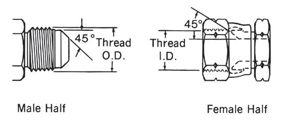
NPTF (National Pipe Tapered Fuel)
This connection is still widely used in fluid power systems, even though it is not recommended by the National Fluid Power Association (NFPA) for use in hydraulic applications. The thread is tapered and the seal takes place by deformation of the threads.
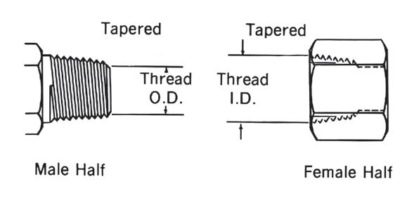
NPTF Threads
Measure thread diameter and subtract 1/4-inch to find the nominal pipe size.
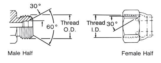
This connection is sometimes used in fluid power systems. The female half has a straight thread and an inverted 30° seat. The male half of the connection has a straight thread and a 30° internal chamfer. The seal takes place by compression of the 30° seat on the chamfer. The threads hold the connection mechanically. Note: A properly chamfered NPTF male will also seal with the NPSM female.
14
Nominal Inch Dash Thread Male Thread Female Thread Size Size Size O.D. Inch I.D. Inch Fraction Decimal Fraction Decimal 1/8 02 1/8-27 13/32 0.41 3/8 0.38 1/4 04 1/4-18 17/32 0.54 1/2 0.49 3/8 06 3/8-18 11/16 0.68 5/8 0.63 1/2 08 1/2-14 27/32 0.84 25/32 0.77 3/4 12 3/4-14 1-1/16 1.05 1 0.98 1 16 1-11-1/2 1-5/16 1.32 1-1/4 1.24 1-1/4 20 1-1/4-11-1/2 1-21/32 1.66 1-19/32 0.58 1-1/2 24 1-1/2-11-1/2 1-29/32 1.90 1-13/16 1.82 2 32 2-11-1/2 2-3/8 2.38 2-5/16 2.30
Nominal Inch Dash Thread Male Thread Female Thread Size Size Size O.D. Inch I.D. Inch Fraction Decimal Fraction Decimal 1/8 02 1/8-27 13/32 0.41 3/8 0.38 1/4 04 1/4-18 17/32 0.54 1/2 0.49 3/8 06 3/8-18 11/16 0.68 5/8 0.63 1/2 08 1/2-14 27/32 0.84 25/32 0.77 3/4 12 3/4-14 1-1/16 1.05 1 0.98 1 16 1-11-1/2 1-5/15 1.32 1-1/4 1.24 1-1/4 20 1-1/4-11-1/2 1-21/32 1.66 1-19/32 0.58 1-1/2 24 1-1/2-11-1/2 1-29/32 1.90 1-13/16 1.82 2 32 2-11-1/2 2-3/8 2.38 2-5/16 2.30 Page 13
NPSM (National Pipe Straight Mechanical)
Application Data Thread Identification
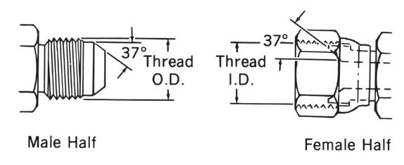
American Connections SAE J514 37° Hydraulic
This connection is very common in fluid power systems. Both the male and female halves of the connections have 37° seats. The seal takes place by establishing a line contact between the male flare and the female cone seat.
The threads hold the connection mechanically.
Caution: S
In the –02, –03, –04, –05, –08 and –10 sizes, the threads of the SAE 45° flare and the SAE 37° flare are the same. However, the sealing surface angles are not the same.
15
Nominal Inch Dash Thread Male Thread Female Thread Size Size Size O.D. Inch I.D. Inch Fraction Decimal Fraction Decimal 1/8 02 5/16-24 5/16 0.31 9/32 0.27 3/16 03 3/8-24 3/8 0.38 11/32 0.34 1/4 04 7/16-20 7/16 0.44 13/32 0.39 5/16 05 1/2-20 1/2 0.50 15/32 0.45 3/8 06 9/16-18 9/16 0.56 17/32 0.51 1/2 08 3/4-16 3/4 0.75 11/16 0.69 5/8 10 7/8-14 7/8 0.88 13/16 0.81 3/4 12 1-1/16-12 1-1/16 1.06 1 0.98 7/8 14 1-3/16-12 1-3/16 1.19 1-1/8 1.13 1 16 1-5/16-12 1-5/16 1.31 1-1/4 1.23 1-1/4 20 1-5/8-12 1-5/8 1.63 1-9/16 1.54 1-1/2 24 1-7/8-12 1-7/8 1.88 1-13/16 1.79 2 32 2-1/2-12 2-1/2 2.50 2-7/16 2.42
Page 14
Application Data
Thread Identification
American Connections
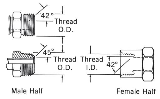
SAE J512 Inverted
This connection is frequently used in automotive systems. The male connector can either be a 45° flare in the tube fitting form or a 42° seat in the machined adapter form. The female has a straight thread with a 42° inverted flare. The seal takes place on the flared surfaces. The threads hold the connection mechanically.
16
Nominal Inch Dash Thread Male Thread Female Thread Size Size Size O.D. Inch I.D. Inch Fraction Decimal Fraction Decimal 1/8 02 5/16-28 5/16 0.32 9/32 0.28 3/16 03 3/8-24 3/8 0.38 11/32 0.34 1/4 04 7/16-24 7/16 0.44 13/32 0.40 5/16 05 1/2-20 1/2 0.50 15/32 0.45 3/8 06 5/8-18 5/8 0.63 9/16 0.57 7/16 07 11/16-18 11/16 0.69 5/8 0.63 1/2 08 3/4-18 3/4 0.75 23/32 0.70 5/8 10 7/8-18 7/8 0.88 13/16 0.82 3/4 12 1-1/16-16 11/16 1.06 1 1.00
Page 15
Application Data
Thread Identification
This connection is commonly used in refrigeration, automotive and truck piping systems. The connector is frequently made of brass. Both the male and female connectors have 45° seats. The seal takes place between the male flare the female cone seat. The threads hold the connection mechanically.
Caution: S
In the –02, –03, –04, –05, –08 and –10 sizes, the threads of the SAE 45° flare and the SAE 37° flare are the same. However, the sealing surface angles are not the same.
17
Nominal Inch Dash Thread Male Thread Female Thread Size Size Size O.D. Inch I.D. Inch Fraction Decimal Fraction Decimal 1/8 02 5/16-24 5/16 0.31 9/32 0.27 3/16 03 3/8-24 3/8 0.38 11/32 0.34 1/4 04 7/16-20 7/16 0.44 13/32 0.39 5/16 05 1/2-20 1/2 0.50 15/32 0.45 3/8 06 5/8-18 5/8 0.63 9/16 0.57 1/2 08 3/4-16 3/4 0.75 11/16 0.69 5/8 10 7/8-14 7/8 0.88 13/16 0.81 3/4 12 1-1/16-14 1-1/16 1.06 1 0.99 7/8 14 1-1/4-12 1-1/4 1.25 1-5/32 1.16 1 16 1-3/8-12 1-3/8 1.38 1-9/32 1.29
American Connections SAE J512 45°
Page 16
Application Data
Thread Identification
British Connections
British Standard Pipe (BSP)
This BSPT (tapered) connection is similar to the NPT, except that the thread pitches are different in most sizes, and the thread form and O.D.s are close but not the same. Sealing is accomplished by thread distortion. A thread sealant is recommended.
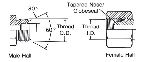
The BSP (parallel) male is similar to the NPSM male except the thread pitches are different in most sizes. The female swivel BSPP has a tapered nose/Globeseal flareless swivel which seals on the cone seat of the male.
*Frequently, the thread size is expressed as a fractional dimension preceded by the letter “G” or the letter “R”. The “G” represents a parallel thread and the “R” indicates a tapered thread. For example, BSPP 3/8–19 may be expressed as G 3/8, and BSPT 3/8–19 may be expressed as R3/8.
18
Nominal Inch Dash Thread Male Thread Female thread Size Size Size* O.D. Inch I.D. Inch Fraction Decimal Fraction Decimal 1/8 02 1/8–28 3/8 0.38 11/32 0.35 1/4 04 1/4–19 33/64 0.52 15/32 0.47 3/8 06 3/8–19 21/32 0.65 19/32 0.60 1/2 08 1/2–14 13/16 0.82 3/4 0.75 5/8 10 5/8–14 7/8 0.88 13/16 0.80 3/4 12 3/4–14 11/32 1.04 31/32 0.97 1 16 1–11 15/16 1.30 1-7/32 1.22 1-1/4 20 1-1/4–11 1-21/32 1.65 1-9/16 1.56 1-1/2 24 1-1/2–11 1-7/8 1.88 1-25/32 1.79 2 32 2–11 2-11/32 2.35 2-1/4 2.26
BSPT/BSPP Threads
Page 17
Application Data
Tubing Selection
To select tubing for a particular installation, two factors must be determined…
Tubing Types
1. Tubing Type: material and construction
2. Size: Inside diameter (I.D.) and wall thickness. Information listed below will aid in your tubing selection. Commercial tubing is available in a wide variety of materials, types of construction and quality. Each is best suited for certain specific applications.
Aluminum Tubing
Seamless annealed is approved by SAE for low pressure applications.
Copper Tubing: Seamless fully annealed coils and fully annealed or quarter-hard straight lengths can be used for systems that do not use petroleum based fluids (copper acts as an oil-oxidation catalyst, causing sludge). Copper also tends to work harden when flared or bent and has poor resistance to vibration. Therefore, the use of copper tubing is limited to low-pressure stationary applications and air circuits.
Special Alloy Tubing: May be required for specific corrosion problems. Information on these applications can be obtained from your tubing supplier or from tubing manufacturers.
Tubing Size
The two variables in tubing size are the inside diameter (ID) and the wall thickness. Each of these is dependent upon a number of factors.
Inside Diameter –
The tubing I.D. will determine the flow and velocity of the fluid in the system. Flow is the volume of fluid that is to be moved through the line to perform a given job within a specified time. Flow rate is expressed in gallons per minute (gpm).
Velocity is the rate of speed at which the fluid passes through the line. It is expressed in feet per second (fps). With a given flow rate, the velocity will increase as the inside diameter of the tubing decreases.
Note:
To determine the appropriate tubing I.D. for specific flow rate and velocity, refer to the Velocity vs. Flow chart on page 21.
Wall Thickness
The required wall thickness of the tubing depends upon operating pressure, safety factor, temperatures, and tubing material.
Operating Pressure is the pressure of the fluid in the system. It is expressed in pounds per square inch (psi).
Refer to safety information regarding proper selection of tubing and tube connectors on page 5.
Safety Factor is a multiplier applied to the wall thickness that compensates for additional mechanical strains and hydraulic shocks to which the tubing may be subjected during operation.
Note:
To determine the appropriate wall thickness, refer to the data on page 22.
Pressure Drop
Total pressure supplied to a line must equal usable pressure (or output) plus the pressure that is lost through fluid transmission, which is referred to as pressure drop. These pressure drops cause loss of energy and should be kept to a minimum. Elements which cause pressure drop in the transmission of fluids include sudden enlargements or contractions, bends, fittings and valves. Mathematical analysis of pressure drop, although possible, is not precise because of the interrelationship of factors such as fluid velocity, density, flow area and friction coefficients. Therefore, to obtain optimum efficiency, the system (or the questionable portions of the system) should be mocked-up to obtain empirical pressure drop data.
19
Page 18
Application Data
Tubing Selection
Following is a typical problem that illustrates, step by step, the procedure for determining tube size.
Select Bundyweld tubing with the appropriate I.D. and wall thickness for the following conditions:
1. Using the Flow/Velocity chart on Page 21, follow the horizontal flow line (5 gpm) until it intersects the vertical velocity line (10fps). From this point, follow the diagonal line upward to get the required tube I.D. (.444). If the horizontal flow line and the vertical velocity line intersect between two diagonal lines, normally the larger inside diameter would be selected since it would mean less velocity.
2. Refer to the chart of Standard Size Hydraulic Tubing, below. Note that .444 I.D. tubing is not listed. If you want to use standard tubing, select one with a larger I.D. Do not select a smaller size since this would increase
Flow –– 5 gpm
Velocity –– not to exceed 10 fps
Pressure — 2000 psi Safety Factor –– 4:1
Refer to safety information regarding proper selection of tubing and tube connectors on page 5.
the velocity to over the 10 fps limit. Therefore, by going to the next largest size, you would select the 5/8” O.D. tubing having an I.D. of .459 and a wall thickness of .083.
3. To determine whether this tubing will meet the pressure and safety factor requirements, refer to the Recommended Wall Thickness data on page 18. For 5/8” O.D. tubing at 2000 psi, the chart for Bundyweld indicates that the minimum wall thickness with a safety factor of 4:1 is .05952. Since you have selected a tubing with a .083 wall, this would easily fulfill the requirements. However, for savings on weight and cost, you can select
another tubing with a thinner wall that will still meet the performance requirements. Therefore, refer again to the chart on standard size tubing and select a tubing with a wall thickness closer to the minimum requirements. This would be the 5/8” O.D. tubing with a .509 I.D. and a .058 wall. This tubing will handle the pressure requirements of 2000 psi with a safety factor of 4:1, and also provides the required flow while keeping the velocity within the 10 fps limitation.
20
Standard Size Hydraulic Tubing Tube Tube Tube O.D. I.D. Wall Tube Tube Tube O.D. I.D. Wall Tube Tube Tube O.D. I.D. Wall Tube Tube Tube O.D. I.D. Wall 1/8” .055 .035 .061 .032 .065 .030 .069 .028 3/16” .117 .035 .123 .032 .127 .030 1/4” .120 .065 .134 .058 .152 .049 .166 .042 .180 .035 .190 .030 5/16” .182 .065 .196 .058 .214 .049 .228 .042 .242 .035 .248 .032 3/8” .245 .065 .259 .058 .277 .049 .291 .042 .305 .035 .311 .032 1/2” .310 .095 .334 .083 .358 .072 .370 .065 .384 .058 .402 .049 .416 .042 .430 .035 .436 .032 5/8” .435 .095 .459 .083 .481 .072 .495 .065 .509 .058 .527 .049 .541 .042 .555 .035 3/4” .532 .109 .560 .095 3/4” .584 .083 .606 .072 .620 .065 .634 .058 .652 .049 .680 .035 7/8” .657 .109 .685 .095 .709 .083 .731 .072 .745 .065 .759 .058 .777 .049 1” .760 .120 .782 .109 .810 .095 .834 .083 .856 .072 .870 .065 .884 .058 .902 .049
Problem Solution
Page 19
Application Data
Tubing Selection
Flow/Velocity Chart
To Find Required Tube I.D.
Flow–20 gpm
Velocity–9 fps
Follow horizontal flow line (20 gpm) until it intersects vertical velocity line (9 fps). From this point follow diagonal line to get required Tube I.D. –(.944).
To Find Permissible Flow Velocity–15 fps Tube I.D.–.495
Follow vertical velocity line (15 fps) until it intersects diagonal line representing .495 tube I.D. Then project this point horizontally to get the permissible flow–(9 gpm).
To Find Velocity of Fluid in System
Flow–6 gpm Tube I.D.–.694
Follow horizontal flow line (6 gpm) until it intersects diagonal line representing .694 tube I.D. Then project this point vertically downward to get the velocity of fluid –(5 fps).
21
Page 20
Application Data
Tubing Selection
With the following recommended wall thickness tables the tubing wall can be selected that is best suited for a particular application. The data given in these tables are raw figures based on the equation:
t= Dp(FS)
2S
t – wall thickness (inches)
D – O.D. of tube (inches)
p – pressure (psi)
FS – Safety Factor
S – tensile strength of tubing material
Therefore, many of the wall thicknesses given in these tables are not found on standard tubing, but serve to establish the minimum wall required.
Safety Factor
The standard safety factors indicate three grades of severity of service:
4:1 – mechanical and hydraulic shocks not excessive
6:1 – considerable mechanical strain and hydraulic shock
8:1 – hazardous applications with severe service conditions
The wall thickness shown in these tables are based on ultimate strength of material and a safety factor of 4:1.
To obtain the recommended wall for a specific pressure based on a safety factor of
6:1, multiply the wall thickness indicated in the table by 1.5. For a safety factor of 8:1, multiply by 2
Temperature
The wall thickness found by using these tables can be corrected for temperature by multiplying the wall thickness by the appropriate correction factor given in the chart below. The table is based on strength reduction due to increased temperature.
Shaded Areas
Tubing wall thickness listed in the shaded areas are generally either too light or too heavy for practical applications, and are listed only to provide data for accurate computation.
S=4)
Refer to safety information regarding proper selection of tubing and tube connectors on page 5.
(UNS C12200 Light Drawn)
22 Copper
Based on 40,000#/IN.2,
–4) Working Pressure (psi) 1,000 2,000 3,000 4,000 5,000 .00625 .01250 .01875 .02500 .03125 .00938 .01875 .02812 .03750 .04688 .01250 .02500 .03750 .05000 .06250 .01562 .03125 .04688 .06250 .07812 .01875 .03750 .05625 .07500 .09375 .02500 .05000 .07500 .10000 .12500 .03125 .06250 .09375 .12500 .15625 .03750 .07500 .11250 .15000 .18750 .04375 .08750 .13125 .17500 .21875 .05000 .10000 .15000 .20000 .25000 .06250 .12500 .18750 .25000 .31250 .07500 .15000 .22500 .30000 .37500 10000 .20000 .30000 .40000 .50000 Annealed Copper Based on 30,000#/IN.2, Strength (F.S. –4) Tube Working Pressure (psi) O.D. 1,000 2,000 3,000 4,000 5,000 1/8 .00833 .01667 .02500 .03333 .04167 3/16 .01250 .02499 .03750 .04999 .06250 1/4 .01667 .03333 .05000 .06666 .08333 5\16 .02083 .04167 .06250 .08333 .10417 3\8 .02499 .04999 .07500 .09999 .12499 1\2 .03333 .06667 .10000 .13333 .16667 5\8 .04167 .08333 .12500 .16666 .20883 3\4 .04999 .09999 .15000 .19999 .24999 7/8 .05833 .11667 .17500 .23333 .29166 1 .06667 .13333 .20000 .26666 .33333 1-1/4 .08333 .16667 .25000 .33333 .41667 1-1/2 .09999 .19999 .30000 .39999 .49999 2 .13333 .26667 .40000 .53333 .66667 Aluminum 5052 (H-32) Based on 31,000#/IN.2, Strength (F.S. –4) Working Pressure (psi) 1,000 2,000 3,000 4,000 5,000 .00806 .01613 .02419 .03226 .04032 .01210 .02419 .03629 .04839 .06048 .01613 .03226 .04839 .06452 .08065 .02016 .04032 .06048 .08065 .10081 .02419 .04839 .07258 .09677 .12097 .03227 .06452 .09677 .12903 .16129 .04032 .08065 .12097 .16129 .20161 .04839 .09677 .14516 .19355 .24194 .05645 .11290 .16935 .22581 .28226 .06452 .12903 .19355 .25806 .32258 .08065 .16129 .24194 .32258 .40323 .09677 .19355 .29032 .38710 .48387 .12903 .25806 .38710 .51613 .64516 Aluminum 3003 (H-14) Based on 20,000#/IN.2, Strength (F.S. –4) Tube Working Pressure (psi) O.D. 1,000 2,000 3,000 4,000 5,000 1/8 .01250 .02500 .3750 .05000 3/16 .01875 .03750 .05650 .07500 1/4 .02500 .05000 .07500 .10000 5/16 .03125 .06250 .09375 .12500 3/8 .03750 .07500 .11250 .15000 1/2 .05000 .10000 .15000 .20000 5/8 .06250 .12500 .18750 .25000 3/4 .07500 .15000 .22500 .30000 7/8 .08750 .17500 .26250 .35000 1 .10000 .20000 .30000 .40000 1-1/4 .12500 .25000 .37500 .50000 1-1/2 .15000 .30000 .45000 .60000 2 .20000 .40000 .60000 .80000
Strength (F.S.
Tube Working Pressure (psi) O.D. 1,000 2,000 3,000 4,000 5,000 1/8 .00595 .01190 .01786 .02381 .02976 3/16 .00893 .01786 .02679 .03571 .04464 1/4 .01190 .02381 .03571 .04762 .05952 5/16 .01488 .02976 .04464 .05952 .07440 3/8 .01786 .03571 .05357 .07143 .08929 1/2 .02381 .04762 .07143 .09524 .11905 5/8 .02976 .05952 .08929 .11905 .14881 Recommended Wall Thickness Temperature Copper Aluminum +100F. 1.00 1.00 +200F 1.08 1.00 +300F 1.22 1.08 +400F 2.30 1.41 +500F – 2.10 +600F – –+700F – –+800F – –+900F – –+1000F. – –
Bundyweld Based on 42,000#/IN.2 Strength (F
Page 21
Application Data
Flare Dimensions
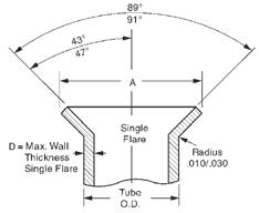
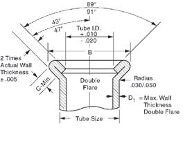
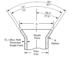
23 JIC 37° Flare Tubes (SAE J533) 65º 73º B 75º 36.5º 37.5º D= R Radius Tube O.D. Double Flare Max. Wall Thickness Double Flare 67º Tube I.D. +.040 Maximum Wall Thickness Tube Single Flare Double Flare R Single Double Size A Diameter B Diameter Radius Flare Flare O.D. Max. Min. Max. Min. ±.020 D D 1/8 0.200 0.180 0.200 0.180 0.030 0.035 0.025 3/16 0.280 0.260 0.280 0.260 0.030 0.035 0.028 1/4 0.360 0.340 0.360 0.340 0.030 0.065 0.035 5/16 0.430 0.400 0.430 0.400 0.030 0.065 0.035 3/8 0.490 0.460 0.490 0.460 0.040 0.065 0.049 1/2 0.660 0.630 0.660 0.630 0.060 0.083 0.049 5/8 0.790 0.760 0.790 0.760 0.060 0.083 0.049 3/4 0.950 0.920 0.960 0.920 0.080 0.109 0.049 7/8 1.070 1.040 1.070 1.040 0.080 0.109 0.065 1 1.200 1.170 1.200 1.170 0.090 0.120 0.065 1 1/4 1.510 1.480 1.510 1.480 0.090 0.120 0.065 1 1/2 1.730 1.700 1.730 1.700 0.110 0.120 0.065 2 2.360 2.330 2.360 2.330 0.110 0.134 0.065 65º 73º A 75º 36.5º 37.5º D1= R Radius Tube O.D. Single Flare Max. Wall Thickness Single Flare 67º
D1= Radius .030/.050 Tube Size 2 Times Actual Wall Thickness ±.005 C-Min. Max. Wall Thickness Double Flare Tube I.D. +.010 -.020 89º 91º 43º 47º B Double Flare 47º 89º A 91º D1= Radius .010/.030 Tube O.D. Single Flare Max. Wall Thickness Single Flare 43º Double Maximum Coined Wall Thickness Single Flare Single Flare Flare Single Double Tube A Diameter B Diameter Seat Flare FLare Size Max. Min. Max. Min. Length C D D1 1/8 0.171/ 0.181 0.198/ 0.213 0.040 0.035 0.025 3/16 0.239/ 0.249 0.265/ 0.280 0.040 0.035 0.028 1/4 0.315/ 0.325 0.345/ 0.360 0.040 0.049 0.035 5/16 0.388/ 0.404 0.410/ 0.425 0.062 0.049 0.035 3/8 0.471/ 0.487 0.485/ 0.500 0.062 0.065 0.049 7/16 0.545/ 0.561 0.555/ 0.570 0.062 0.065 0.049 1/2 0.607/ 0.623 0.625/ 0.640 0.062 0.083 0.049 9/16 0.660/ 0.676 0.697/ 0.712 0.062 0.083 0.049 5/8 0.732/ 0.748 0.757/ 0.772 0.062 0.095 0.049 3/4 0.900/ 0.916 0.897/ 0.912 0.062 0.109 0.049 7/8 1.025/ 1.041 – 0.109 –1 1.141/ 1.157 – 0.120 –
(SAE
Page 22
SAE 45° Flare Tubes
J533)
Application Data
Tubing Installation
Note:
Springing the tubing to force alignment places strain on fitting joints.
Nearly all industrial equipment now in service makes some use of fluid lines. From an economic point of view, the best fluid lines system is that which is easiest to maintain at the lowest original cost. The use of tubing and tube connectors on lines up to 2” diameter is usually more economical than the use of pipe and pipe connectors in modern installations. A few of the more important reasons follow:
1. Size for size, tubing is lighter weight, easier to handle and can be bent more easily than iron pipe.
2. Ductile hydraulic tubing reduces the number of connections required, thus reducing material and labor costs. Bent tubing also reduces pressure drop and turbulence in the system.
3. Fewer joints means lower costs and fewer points of potential leakage.
4. The use of tube connectors makes every joint a
union, permitting easier, faster maintenance and repair work.
5. Modern flared and flareless tube fittings eliminate the need for threading, soldering, or welding.
Tube Bending Tubing should be bent wherever possible to reduce the number of connectors.
Copper tubing can be bent easily with a hand bender. Steel tubing can be bent in sizes 1/8” to 5/8” O.D. by using a hand bender designed for steel tubing. For production quantities, or for sizes larger than 5/8” O.D., a power bender is generally used.
Tubing should be bent accurately. Tubing manufacturers will advise the correct radii for various types and wall thicknesses of tubing. Kinks, flattened bends, wrinkles and tube breakage or loss should be avoided by the use of proper tube bending equipment.
Precautions
Avoid straight line connections wherever possible, especially in short runs. Design piping systems symmetrically. They are easier to install and present a neat appearance.
Care should be taken to eliminate stress from tubing lines. Long tubing runs should be supported by brackets or clips. All parts installed on tubing lines such as heavy fittings, valves, etc., should be bolted down to eliminate tubing fatigue.
Before installing tubing, inspect the tube to see that it conforms to the required specifications, is of the correct diameter and wall thickness and is not out of round.
Cut tube ends reasonably square and lightly deburr inside and outside edge. Chamfer on outside edge will destroy bearing of tube end on the connector seat.
To avoid difficulty in assembly and disconnecting, a sufficient straight length of
tube must be allowed from the end of the tube to the start of the bend. Allow twice the length of the nut as a minimum.
Tubes should be formed to assemble with true alignment to the center line of the fittings, without distortion or tension. Tubing which has to be sprung from position, “A”, (see Fig. 4), to be inserted into the connector has not been properly fabricated, and when so installed and connected, places the tubing under stress.
When assembling the tubing, insert the longer leg to the connector as at “C” (Fig. 4). With the nut free, the short leg of the tubing can be easily moved and brought to proper position with and inserted into the seat in connector “D”. The nuts can then be tightened as required.
24 Right Right Right
A D C
Figure 4
Wrong
Figure 1
Wrong
Figure 2
Wrong
Figure 3
Page 23
Application Data Chemical Compatibility Chart
These tables alphabetically list commonly used materials of various chemical composition. After each agent listing you will find the basic tubing and connector materials rated according to their chemical resistance to each individual agent. The chart is intended to be used as a guide only. Many factors (concentration, temperature, intermittent or continuous exposure, etc.) have a
bearing upon the suitability of any tubing or connector for any specific application, and these factors must be considered by you as you review the chemical compatibility chart.
Where unusual conditions exist or where questions arise, consult Eaton for expert assistance on your tubing application requirements.
Refer to safety information regarding proper selection of tubing and tube connectors on page 5.
Note:
All data given herein is believed to be accurate and reliable but presented without guarantee, warranty, or responsibility of any kind, express or implied, on our part. Chemical resistance will vary with the wide diversity of possible mixtures and service conditions. It is not therefore possible to give any guarantee whatsoever in individual cases. Eaton Eclipse® and Solstice™ tubing should only be used in air brake applications.
25 Codes: G = Good Resistance F = Fair Resistance X = Incompatible – = No data available + = Call Technical Support for specific application Nylon 11 Nylon 6/6 PVC Polyethylene Fluid MTP160 PT230 PT200 PT240 (LDPE) Brass Acetaldehyde G F X X G Acetic Acid (Concentrated) X X X X X Acetic Acid (Dilute) F X F G X Acetic Anhydride X X X X X Acetone G F X G G Acrylonitrile G G — Air G G G G G Alcohols Amyl Alcohol G G X G G Butyl Alcohol, Butanol G G X G G Ethyl Alcohol, Ethanol G G F G G Isopropyl Alcohol, Isopropanol G G G G G Methyl Alcohol, Methanol G G X G G Aluminum Chloride X X G G X Aluminum Fluoride X X G G X Aluminum Hydroxide G G G G X Aluminum Nitrate G F G G X Aluminum Sulfate G F G G X Alums F G G G X Ammonia, Anhydrous Use approved anhydrous ammonia hose X Ammonia Solution (10%) G X G G X Ammonium Chloride X X G G X Ammonium Hydroxide G X X G X Ammonium Nitrate G G G G X Ammonium Phosphate G G F G X Ammonium Sulfate G G G G X Amyl Acetate G G X X G Amyl Alcohol G G X G G Aniline X X X X X Aniline Dyes X X X X X Animal Oils and Fats G G X G Anti-Freeze (Glycol Base) G G F G Aqua Regia X X X X Aromatic Hydrocarbons G G X G G Asphalt Emulsion G X G Barium Chloride G G G G Barium Hydroxide G G G G X Barium Sulfate G G G G G Barium Sulfide X G G X Beet Sugar Liquors G G G G X Benzaldehyde G G X X F
Page 24
Application Data
Chemical Compatibility Chart
Refer to safety information regarding proper selection of tubing and tube connectors on page 5.
26 Nylon 11 Nylon 6/6 PVC Polyethylene Fluid MTP 160 PT230 PT200 PT240 (LDPE) Brass Benzene, Benzol G G X X G Benzoic Acid X X X G G Black Sulfate Liquor X X X G X Bleach Solution X X F G X Borax Solution G G G G Boric Acid G G G G G Brake Fluid (Glycol Ether Base) G X X G Brine G G G G Bromine X X X X X Butane Use Butane approved hose Butyl Acetate G X X G Butyl Alcohol, Butanol G G X G G Calcium Bisulfite G X G G X Calcium Chloride G X G G X Calcium Hydroxide G G G G G Calcium Hypochlorite X X G G G Cane Sugar Liquors G G G G Carbon Dioxide (Dry) G G G G G Carbon Dioxide (Wet) G G G G F Carbon Disulfide (Bisulfide) X X X X G Carbon Monoxide (Hot) X X X X G Carbon Tetrachloride G G X X G Carbonic Acid G G G X Castor Oil G G X G Cellosolve Acetate G X X Chlorinated Solvents F G X X G Chloroacetic Acid X X X X X Chlorobenzene X X X X F Chlorine Gas (Dry) X X X X G Chlorine Gas (Wet) X X X X X Chloroform F G X X G Chlorosulfonic Acid X X X X X Chromic Acid (under 25%) X X F F X Chromic Acid (over 25%) X X X X X Citric Acid X F G G X Coke Oven Gas G X G F Copper Chloride X X G G X Copper Cyanide G G G G X Copper Sulfate G G G G X Corn Syrup (Non-food) G G G — Cottonseed Oil G F G G Creosote X X X X F Cresol X X X X — Cyclohexanol G G X F G Dextrose (Food Grade) X X X G — Dichlorobenzene G X X — Diesel Fuel G X X G Diethanolamine G X X Diethylenetriamine X X X G — Dowtherm A X X X X X Enamel (Solvent Base) G X G G Ethanolamine G X G X Ethers (Ethyl Ether) G X X G Ethyl Alcohol G G F G G Ethyl Acetate G G X G G Ethyl Acrylate X X — Ethyl Methacrylate X X — Ethylamine X X X G G Codes: G = Good Resistance F = Fair Resistance X = Incompatible – = No data available + = Call Technical Support for specific application
Page 25
Application Data
Chemical Compatibility Chart
Refer to safety information regarding proper selection of tubing and tube connectors on page 5.
27 Codes: G = Good Resistance F = Fair Resistance X = Incompatible – = No data available + = Call Technical Support for specific application Nylon 11 Nylon 6/6 PVC Polyethylene Fluid MTP 160 PT230 PT200 PT240 (LDPE) Brass Ethyl Cellulose F X G G Ethyl Chloride G X X G Ethylenediamine X X X G G Ethylene Dibromide F X — Ethylene Dichloride F X X F Ethylene Glycol G G G G G Ethylene Oxide G X X X Fatty Acids G G G G F Ferric Chloride 5% G G G G X Ferric Sulfate G G G G X Fertilizer Salts Solution F G G Formaldehyde G G X G G Formic Acid X X X G F Freon 12 Use approved Freon 12 hose G Freon 134a Use approved Freon 134a hose Fuel Oil G F X G Furfural X X X X G Gasoline (Refined) G G X X G Gasoline (Unleaded) G G X X G Gasoline (10% Ethanol) G G X X G Gasoline (10% Methanol) G G X X G Glucose (non-food) G G G G G Glycerine, Glycerol (Non-food) G G G G G Greases G G G G G Green Sulfate Liquor X X G G X Heptane G G X X G Hexane G G X X G Houghto Safe 273 to 640 G F G G Houghto Safe 5046, 5047F G G G G Houghto Safe 1000 Series G X X G Hydraulic Oils Straight Petroleum Base G G G G G Water Petroleum Emulsion G F G Water Glycol G G X G Straight Phosphate Ester G G X X G Phos. Ester/Petroleum Blend G G X X G Polyol Ester G G Hydrobromic Acid (under 48%) X X G G X Hydrochloric Acid X X G G X Hydrocyanic Acid X X G G G Hydrofluoric Acid (under 50%) X X F F X Hydrofluoric Acid (over 50%) X X X X X Hydrofluosilicic Acid X X G G X Hydrogen Use approved hydrogen hose or metal tubing G Hydrogen Peroxide X X G X Hydrogen Sulfide X X G G G Hydrolube G G G G Iodine X X X X X Isocyanates X X X X Isopropyl Alcohol, Isopropanol G G G G G Isopropylamine X X G Iso-Octane G G X X G Jet Fuel (Transfer Only) G G X X G Kerosene G G X X G Lacquer G G X F G Lacquer Solvents G G X F G Lactic Acid G G G G F Lime Sulfur G F G G X
Page 26
Application Data
Chemical Compatibility Chart
Codes:
G = Good Resistance
F = Fair Resistance
X = Incompatible – = No data available + = Call Technical Support for specific application
Refer to safety information regarding proper selection of tubing and tube connectors on page 5.
28
Nylon 11 NYLON 6/6 PVC POLYETHYLENE FLUID MTP 160 PT230 PT200 PT240 (LDPE) BRASS Lindol G G — F Linseed Oil G G G G G Lubricating Oils G G G G G Lye G F G G F Magnesium Chloride G G G G F Magnesium Hydroxide G G G G G Magnesium Sulfate G G G G G Mercuric Chloride X X F G X Mercury G G F G X Methyl Alcohol, Methanol G G X G G Methyl Acrylate X X X G Methyl Bromide G F X X G Methyl Chloride G G X X G Methylene Chloride F F X X G Methyl t-Butyl Ether (MTBE) G G X Methyl Ethyl Ketone G G X G G Methyl Isobutyl Ketone G G X G G Methyl Isopropyl Ketone G G X G G Methyl Methacrylate X X Mineral Oil G G F X G Mineral Spirits G G X G G Naphtha G G X G Napthalene G G X X G Nickel Acetate G G G G F Nickel Chloride G G G G X Nickel Sulfate G G G G G Nitric Acid (under 35%) X X G F X Nitric Acid (35% to 60%) X X F X X Nitric Acid (over 60%) X X X X X Nitrobenzene X X X G Nitrogen Gas G G G G G Nitrous Oxide F F X X G Oleic Acid G G F G G Oleum (Fuming Sulfuric Acid) X X X X X Oxalic Acid X X G G F Oxygen (non-breathing,non-welding) + G G G G G Ozone (300 pphm) X X X X Paint (Solvent Base) G G X F G Palmitic Acid G G F G X Paper Mill Liquors X X X X Pentane G X X G Perchloroethylene F G X X G Petroleum Ether G G X X G Petroleum Oils G G G G G Phenol X X X X G Phosphoric Acid (to 85%) X X G G G Picric Acid (Molten) X X X X X Picric Acid (Solution) X X X X X Potassium Chloride G G G G F Potassium Cyanide G G G G X Potassium Dichromate F G G F Potassium Hydroxide G F G G F Potassium Permanganate X X G G Potassium Sulfate G G G G F Propane Liquid Use hose approved for Propane Liquid G Propylene Glycol G F G F Pyridine X X X G F Sea Water G G G G G
Page 27
Application Data Chemical Compatibility Chart
Refer to safety information regarding proper selection of tubing and tube connectors on page 5.
29 Nylon 11 Nylon 6/6 PVC Polyethylene Fluid MTP 160 PT230 PT200 PT240 (LDPE) Brass Silver Nitrate G G G G X Skydrol G G X X G Soap Solution Sodium Bicarbonate Sodium Bisulfate G G G G F Sodium Bisulfite G G G G F Sodium Borate G G G G G Sodium Carbonate G G G G G Sodium Chloride G G G G X Sodium Cyanide G G G G X Sodium Hydroxide G F G G F Sodium Hypochlorite X X G G X Sodium Nitrate G G G G F Sodium Perborate G F G G X Sodium Peroxide X X X X X Sodium Phosphates G G G G G Sodium Silicate G G G G G Sodium Sulfate G G G G G Sodium Sulfide G G G G X Sodium Thiosulfate G G G G X Soybean Oil G F G G Stannic Chloride F X G G X Steam 450° F X X X X F Stearic Acid G G F G X Stoddard Solvent G G X X G Styrene G G X X G Sulfur 70º F G G F G X Sulfur 200º F X X X X X Sulfur Chloride X X X G X Sulfur Dioxide X X X X G Sulfuric Acid (under 50%) X X G G X Sulfuric Acid (51% to 70%) X X G X X Sulfuric Acid (71% to 95%) X X X X X Sulfuric Acid (96% to 98%) X X X X X Tannic Acid X X G G G Tar G G X X G Tartaric Acid G G G G F Tetrachloroethane F X F Tetrahydrofuran (THF) G X X Toluene G G X G G Transmission Oil (Petrol. Base) G G G G G Trichloroethane F G X G G Trichloroethylene F G X G G Tung Oil G G Turpentine G G X G G Urea (Water Solution) G G G G Uric Acid G G G G Varnish G G X G G Vegetable Oil (Non-food) G G F G G Vinegar G X G G X Vinyl Acetate G X F Water (non-potable) G G G G G Water-Glycol Mixture G G X G Water-Petroleum Mixture G G F G Xylene G G X G G Zinc Chloride X X G G X Zinc Sulfate G G G G X Codes: G = Good Resistance F = Fair Resistance X = Incompatible – = No data available + = Call Technical Support for specific application
G G G X G G G G G G Page 28
Tubing Plastic Tubing
Typical Application: Soft, pliable, plasticized PVC Resin Tubing, for practically any low pressure laboratory, industrial, agricultural or domestic application.
Note: For plastic tube cutter, see page 143.
Part Number Key:
PT20004RD-100
Natural off-white compound covered under 21CFR177.1500 regulations for food contact.
Application: Semi-rigid general purpose tubing
Range:
Temperature Range: -5°F to +105°F (-20°C to +41°C)
Available Colors: Clear (suffix NA)
Connectors: Polyline pgs. 58-61
SelfAlign pgs. 52-57 with 2030x insert
Compression pgs. 46-51 with 2030x insert
Molded Compression pgs. 132-139
Colors: Natural off-white (NA) and black (BK). FDA colors available on request. Contains: Ultra-Violet Stabilizer in black tubing.
Connectors: SelfAlign pgs. 52-57 Compression pgs. 46-51
Push>Connect pgs. 62-72
Push>Connect Flow Controls pgs. 73-74
Push>Connect Plus pgs. 75-76
30 Catalog Tube Tube Max. Work. Min. Burst Min. Bend Lbs. Per Coil Number O.D. (in) Wall (in) Pres. PSI 75° Pres. PSI 75° Radius 70° F 100 Ft. Length(s) (Ft) PT20004 1/4 (.250) .062 65 195 1.0” 2.00 100 PT20044 1/4 (.250) .040 55 165 1.0” 2.00 100 PT20005 5/16 (.312) .062 55 165 1.25” 2.60 100 PT20006 3/8 (.375) .062 55 165 1.5” 3.30 100 PT20008 1/2 (.500) .062 45 135 2.0” 4.60 100 PT20010 5/8 (.625) .062 30 90 2.5” 5.90 100 PT20012 3/4 (.750) .094 40 120 3.0” 10.3 100 PT20016 1(1.00) .125 35 105 4.0” 18.5 100
PT200 Polyvinyl Chloride
Catalog Color Coil Number Length PT230 Polyamide “Nylon 6/6” Catalog Tube Tube Max. Work. Min. Burst Min. Bend Lbs. Per Coil Number O.D. (in) Wall (in) Pres. PSI 70° Pres. PSI 70° Radius 70° F 100 Ft. Length(s) (Ft) PT23002 1/8 (.125) .015 300 1,000 0.75” 0.3 100, 1,000 PT23003 3/16 (.188) .023 300 1,000 1.25” 0.6 100, 1,000 PT23004 1/4 (.250) .030 300 1,000 1.50” 1.0 100, 1,000 PT23005 5/16 (.312) .036 300 1,000 2.00” 1.5-1.6 100, 1,000 PT23006 3/8 (.375) .040 300 1,000 2.25” 2.1 100, 1,000
Temperature
(-40°C
Available
Typical
-40°F to +180°F
to +82°C)
Page 29
Tubing Plastic Tubing
Meets FDA for food contact. Natural off-white compound covered under 21CFR177.1520 regulations for food contact.
Typical Application: Economical, flexible, low density Polyethylene has a wide range of uses in industrial and agricultural applications.
Temperature Range: -40°F to +135°F (-40°C to +57°C)
Note: For plastic tube cutter, see page 143.
Part Number Key: PT20004RD-100
Typical Application: Flexible nylon tubing. Used for instrumentation; lubrication and air lines; gas, chemical and oil processing; low pressure hydraulics.
Temperature Range: -40°F to +200°F (-40°C to +93°C)
Available Colors: Natural off-white (NA), black (BK), yellow (YW), orange (OR), blue (BU), red (RD), green (GN). FDA colors available on request. Refer to current price list for availability of colors.
Contains: Ultra-Violet Stabilizer in black tubing.
Connectors:
Minibarb pgs. 77-80
Polyline pgs. 58-61
SelfAlign pgs. 52-57 with 2030 insert
Compression pgs. 46-51 with 2030 insert
Push>Connect pgs. 62-72
Push>Connect Flow Controls pgs. 73-74
Push>Connect Plus pgs. 75-76
Molded Compression pgs. 132-139
Available Colors: Black (BK) or natural (NA).
Contains: Ultra-Violet Stabilizer
Connectors:
SelfAlign pgs. 52-57
Compression pgs. 46-51
Connectors (cont.):
Push>Connect pgs. 62-72
Push>Connect Flow Controls pgs. 58, 73-74
Push>Connect Plus pgs. 75-76
Molded Compression pgs. 132-139
31
Catalog Tube Tube Max. Work. Min. Burst Min. Bend Lbs. Per Coil Number O.D. (in) Wall (in) Pres. PSI 70° Pres. PSI 70° Radius 70° F 100 Ft. Length(s) (Ft) PT24004 1/4 (.250) .062 200 600 0.75” 1.50 100, 1,000 PT24044 1/4 (.250) .040 133 400 0.62” 1.00 100, 1,000 PT24005 5/16 (.312) .062 135 480 1.00” 1.90 100, 1,000 PT24006 3/8 (.375) .062 135 400 1.50” 2.40 100, 1,000 PT24008 1/2 (.500) .062 100 300 2.00” 3.40 100, 500 PT24010 5/8 (.625) .062 80 240 2.50” 4.40 100 PT24012 3/4 (.750) .094 70 210 3.00” 7.60 100 PT24016 1 (1.000) .125 100 300 5.00” 13.4 100
PT240 Polyethylene
TP160 Polyamide “Nylon 11”
Catalog Tube Tube Max. Work. Min. Burst Min. Bend Lbs. Per Coil Number O.D. (in) Wall (in) Pres. PSI 70° Pres. PSI 70° Radius 70° F 100 Ft. Length(s) (Ft) TP16002 1/8 (.125) .023 250 1,000 .62” .30 100, 1,000 TP16025 5/32 (.156) .029 250 1,000 1” .75 100, 1,000 TP16004 1/4 (.250) .040 250 1,000 1.25” 1.2 100, 1,000 TP16005 5/16 (.312) .040 250 1,000 2” 2.0 100, 1,000 TP16006 3/8 (.375) .062 250 1,000 3” 2.7 100, 1,000 TP16008 1/2 (.500) .062 250 1,000 4.5” 3.8 100, 500
Catalog Color Coil Number Length
Page 30
Tubing Plastic Tubing
MTP160 Polyamide “Nylon 11” Metric Tubing
Typical Application: Flexible nylon tubing. Used for instrumentation; lubrication and air lines; gas, chemical and oil processing; low pressure hydraulics.
Note: For plastic tube cutter, see page 143.
Part Number Key:
PT20004RD-100
Temperature Range: -40°F to +200°F (-40°C to +93°C)
Available Colors: Natural (NA).
Contains: Ultra-Violet Stabilizer
Connector: Metric Push>Connect pgs. 69-72
32
Catalog Tube Tube Max. Work. Min. Burst Min. Bend Lbs. Per Coil Number O.D. (mm) Wall (mm) Pres. PSI 75° Pres. PSI 75° Radius 75° F 100 Ft. Length(s) (Ft) MTP16004 4 .65 250 1,000 .75" 0.6 100 MTP16005 5 1 250 1,000 1" 0.9 100 MTP16006 6 1 250 1,000 1.5" 1.1 100 MTP16008 8 1 250 1,000 2.25" 1.5 100 MTP16010 10 1 200 800 3" 1.9 100 MTP16012 12 1 112 450 3.5" 2.3 100
Catalog Color Coil Number Length Page 31
Tubing Air Brake Tubing
Eclipse® Air Brake Tubing
Meets SAE J844, 1131, J2494-3 and DOT FMVSS106
Synflex Eclipse Type A Air Brake Tubing
Synflex Eclipse Type B Air Brake Tubing
Features
• Superior abrasion resistance
• East of cutting
• Enhanced flexibility and extension
• Flow performance
Applications
• Truck air brake systems
• Trailer air brake systems
Solstice™ Type A Air Brake Tubing
• Auxiliary air systems
• Formed tubes
• Formed and straight air brake harness assemblies Construction
• Distinctive patented construction
• 100% polyamide construc tion with polyester yarn reinforcement
• UV stabilized
• Thermoformable
• Available in standard and custom colors
• Available in all standard sizes
Temperature Range
• -65°F to 200°F (-54°C to 93°C).
Connectors:
QCAB pages 81-89 1400 series Air Brake pages 90-95
For 1/8” Tubing use Selfalign.
Note: SelfAlign Connectors are not designed to meet DOT standards.
Meets or exceeds the performance requirements SAE J844, J1131, J2494-3, and DOT FMVSS106 Synflex Solstice Type Air Brake Tubing
Applications
• Truck air brake systems
• Trailer air brake systems
• Auxiliary air systems
• Formed tubes
• Formed and straight air brake harness assemblies
• Highly engineered thermoplastic material
• Monowall tubing
• UV stabilized
• Thermoformable
• Available in standard and custom colors
Connectors:
QCAB pages 81-89
1400 Series Air Brake pages 90-95
33 Minimum Nominal Minimum Part Nominal Nominal Bend Wall Burst Number O.D I.D. Radius Thickness Pressure Weight mm in mm in mm in mm in kpa psi kg/100 m lbs/100 ft 4245-022 3.18 1/8 2.01 .079 6.35 1/4 0.58 .023 6,900 1,000 .49 .33 4245-025 3.96 5/32 2.34 .092 12.70 1/2 0.79 .031 8,300 1,200 .83 .56 4245-03 4.77 3/16 2.97 .117 19.05 3/4 0.89 .035 8,300 1,200 1.06 .71 4245-05 7.95 5/16 5.89 .232 28.58 1-1/8 1.02 .040 6,900 1,000 2.29 1.54
Minimum Nominal Minimum Part Nominal Nominal Bend Wall Burst Number O.D I.D. Radius Thickness Pressure Weight mm in mm in mm in mm in kpa psi kg/100 m lbs/100 ft 3270-06 9.53 3/8 6.38 .251 38.10 1.5 1.57 .062 9,700 1,400 4.2 2.8 3270-08 12.70 1/2 9.55 .376 50.80 2.0 1.57 .062 6,600 950 5.8 3.8 3270-10 15.88 5/8 11.20 .441 63.50 2.5 2.34 .092 6,200 900 10.4 7.0 3270-12 19.05 3/4 14.38 .566 76.20 3.0 2.34 .092 5,500 800 12.8 8.6
Part Nominal Nominal Min. Bend Nominal Wall Min Burst Number O.D I.D. Radius Thickness Pressure Weight mm in mm in mm in mm in kpa psi kg/100m lbs/100 ft 4247-041 6.35 ¼ 4.32 .170 25.40 1 1.02 0.04 8,300 1,200 2.20 1.50
Features
Temperature Range (-40°F
200°F) -40°C
93°C
to
to
Page 32
Tubing Air BrakeTubing
34 Eclipse ABT Master Pack Master Pack Part # O.D. Color Quantities Configuration 4245-02207 1/8” black 12,000 ft 6 reels of 2000 ft 4245-02227 1/8” red 12,000 ft 6 reels of 2000 ft 4245-02257 1/8” green 12,000 ft 6 reels of 2000 ft 4245-02267 1/8” blue 12,000 ft 6 reels of 2000 ft 4245-02506 5/32” black 6,000 ft 6 reels of 1000 ft 4245-02526 5/32” red 6,000 ft 6 reels of 1000 ft 4245-02546 5/32” yellow 6,000 ft 6 reels of 1000 ft 4245-02556 5/32” green 6,000 ft 6 reels of 1000 ft 4245-02566 5/32” blue 6,000 ft 6 reels of 1000 ft 4245-03306 3/16” black 6,000 ft 6 reels of 1000 ft 4245-03326 3/16” red 6,000 ft 6 reels of 1000 ft 4245-03356 3/16” green 6,000 ft 6 reels of 1000 ft 4247-04106 1/4” Black 6,000 ft 6 reels of 1000 ft 4247-04156 1/4” Green 6,000 ft 6 reels of 1000 ft 4247-04126 1/4” Red 6,000 ft 6 reels of 1000 ft 4247-04166 1/4” Blue 6,000 ft 6 reels of 1000 ft 4247-041C6 1/4” Brown 6,000 ft 6 reels of 1000 ft 4247-04146 1/4” Yellow 6,000 ft 6 reels of 1000 ft 4247-04136 1/4” Orange 6,000 ft 6 reels of 1000 ft 4247-041D6 1/4” Purple 6,000 ft 6 reels of 1000 ft 4247-04116 1/4” White 6,000 ft 6 reels of 1000 ft 4247-041F6 1/4” Silver 6,000 ft 6 reels of 1000 ft 4245-05204 5/16” black 3,000 ft 6 reels of 500 ft 4245-05224 5/16” red 3,000 ft 6 reels of 500 ft 4245-05244 5/16” yellow 3,000 ft 6 reels of 500 ft 4245-05254 5/16” green 3,000 ft 6 reels of 500 ft 4245-05264 5/16” blue 3,000 ft 6 reels of 500 ft 3270-06104 3/8” black 3,000 ft 6 reels of 500 ft 3270-06124 3/8” red 3,000 ft 6 reels of 500 ft 3270-06134 3/8” orange 3,000 ft 6 reels of 500 ft 3270-06144 3/8” yellow 3,000 ft 6 reels of 500 ft 3270-06154 3/8” green 3,000 ft 6 reels of 500 ft 3270-06164 3/8” blue 3,000 ft 6 reels of 500 ft 3270-08104 1/2” black 1,500 ft 3 reels of 500 ft 3270-08124 1/2” red 1,500 ft 3 reels of 500 ft 3270-08134 1/2” orange 1,500 ft 3 reels of 500 ft 3270-08144 1/2” yellow 1,500 ft 3 reels of 500 ft 3270-08154 1/2” green 1,500 ft 3 reels of 500 ft 3270-08164 1/2” blue 1,500 ft 3 reels of 500 ft 3270-10103 5/8” black 750 ft 3 reels of 250 ft 3270-10123 5/8” red 750 ft 3 reels of 250 ft 3270-10133 5/8” orange 750 ft 3 reels of 250 ft 3270-10143 5/8” yellow 750 ft 3 reels of 250 ft 3270-10153 5/8” green 750 ft 3 reels of 250 ft 3270-10163 5/8” blue 750 ft 3 reels of 250 ft 3270-12103 3/4” black 750 ft 3 reels of 250 ft 3270-12123 3/4” red 750 ft 3 reels of 250 ft 3270-12133 3/4” orange 750 ft 3 reels of 250 ft 3270-12153 3/4” green 750 ft 3 reels of 250 ft 3270-12163 3/4” blue 750 ft 3 reels of 250 ft
Page 33
Brass Products Introduction
Eaton brass tube fittings are made from high quality UNS CA-360 brass bar. Eaton brass connectors are precision machined to meet SAE standards and specifications. Large, uniform wrench pad areas have standard dimensions for easy assembly and disassembly using standard open-end wrenches. On fittings where pipe threads are used, the fittings are standardized on Dryseal American National Standard Taper. Eaton offers the only complete line of brass connectors with these outstanding advantages.
Hot Extrusion
A cast billet is heated and extruded through a die containing the desired configuration. This process recrystallizes the weaker cast structure into the stronger pressed structure of the shaped extrusion.
Cold Draw
The hot extruded shape is pulled through a die with the same configuration but less cross sectional area. This further recrystallizes and refines the structure while increasing the strength and elongation. In addition, the dimensions are brought to close tolerances.
Shapes
The dies through which the billets are forced may be one of hundreds of shapes. Four of the most common shapes, used in the manufacture of Eaton connectors, are illustrated.
Saw and Machine
The cold bar stock is then cut into individual pieces for precision machining. After the part is machined, it is ready for the market as a strong, tough, high quality connector. Only by using this process is it possible to get the big all-flat sides on elbows and tees, instead of the usual small wrench pads, or lack of flats all together.
Microstructure


The photomicrographs illustrate the change in microstructure from the low strength low ductility dendritic structure of the cast billet, to the recrystallized structure of the hot extrusion, to the refined structure of the high strength high ductility cold drawn rod.

35
As Cast – 50x Hot Extruded – 200x
Cold Drawn – 200x
Hot Extrusion
Cold Draw
Page 34
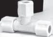
Brass Products
Inverted Flare
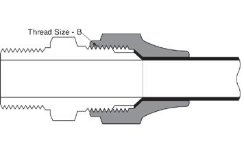
Typical Application: Hydraulic brake, power steering, fuel lines and transmission cooler lines, LP and natural gas (special order).
Pressure: Working pressure up to 2000 psi depending on tube size. Will withstand burst pressure of standard tubing - up to 5000 psi with bundyweld (double flared) and 3500 psi with copper tubing, depending on size.
Vibration: Excellent resistance.
Temperature Range: -65°F to +250°F (-53°C to +121°C) range at maximum operating pressures.
Material:
CA360 Brass.
Used With: Copper, brass, aluminum and steel hydraulic tubing that can be flared. See pages 25-29 for material compatibility.
Note: For additional technical questions, contact Technical Support at 1-888-258-0222.
Refer to safety information regarding proper selection of tubing and tube connectors on page 5.
Advantages: Very low cost and reusable. Seats and threads are internal and protected. Compact, excellent vibration life. Short nut affords very close tube bends. Steel or brass tube nut.
Conformance: Listed by Under writer’s Laboratories (available on special order) for fuel equipment, refrigeration and gas. Meets specifications and standards of ASA, ASME, SAE and MS (Military Standards).
How to Order: Order individually by catalog number.
Note: Refer to current price list for availability of cataloged items. Configurations and dimensions subject to change without notice. Additional information can be found in SAE J512.
Label Set: W-8022 (adhesive) CL-490 (non-adhesive)
Assembly Instructions:
1. Cut tubing to desired length. Make sure all burrs are removed and the ends are cut square.
2. Slide nut on tube. Threaded end “A” of nut must face out.
3. Flare end of tube with a 45° flaring tool. See page 23 for flare data.
a. Measure flare diameter
b. Examine flare for excessive thin out.
c. On thin wall, welded or brazed tubing, use double flare to prevent pinch-off and cracked flares.
4. Lubricate threads and assemble to connector body. Nut should be turned hand tight.
5. Tighten assembly with a wrench until a solid feeling is encountered. From that point, apply a one-sixth turn.
Note:
Do not over-torque as it may damage the connectors or split the tubing at the flare.
36 A
Tube O.D. 1/8 3/16 1/4 5/16 3/8 7/16 1/2 5/8 3/4 7/8 1 Thread 5/16-28 3/8-24 7/16-24 1/2-20 5/8-18 11/16-18 3/4-18 7/8-18 1-1/16-16 1-3/16-16 1-5/16-16 Size-B
Thread Size B
Page 35
Brass Products Inverted Flare
37 Tube Catalog O.D Number C D L 1/8 105x2 5/16 0.132 0.52 3/16 105x3 3/8 0.196 0.56 1/4 105x4 7/16 0.259 0.56 5/16 105x5 1/2 0.321 0.62 3/8 105x6 5/8 0.384 0.66 3/8 105x6x7* 11/16 0.387 0.66 7/16 105x7 11/16 0.444 0.68 1/2 105x8 3/4 0.508 0.74 5/8 105x10 7/8 0.632 0.80 3/4 105x12 1-1/16 0.757 0.88 7/8 105x14 1-3/16 0.882 1.06 1 105x16 1-3/8 1.008 1.18 *3/8" Tube to 11/16-18 Male Thread Tube Nut (Steel) (Ref. SAE No. 040110) Tube Catalog O.D. Number C D L 3/16 100x3 3/8 .196 0.56 1/4 100x4 7/16 .259 0.56 5/16 100x5 1/2 .321 0.62 3/8 100x6 5/8 .384 0.66 1/2 100x8 3/4 .508 0.74 Tube Nut (Brass) (Ref. SAE No. 040110) Tube Catalog O.D Number C D L 3/16 7896x3 3/8 .196 .844 1/4 7896x4 7/16 .257 .812 Tube Nut Long (Steel) L D 90° C L D 90° C L D 90° C Tube Catalog O.D Number C D L 3/16 131x3 3/8 .188 0.53 1/4 131x4 7/16 .188 0.54 5/16 131x5 1/2 .250 0.59 3/8 131x6 5/8 .312 0.66 Plug (Steel) (Ref. SAE No. 040109) 42° D L C Tube Catalog O.D. Number C D L 1/8 302x2 13/32 .078 .59 3/16 302x3 15/32 .125 .62 1/4 302x4 17/32 .188 .62 5/16 302x5 19/32 .219 .70 3/8 302x6 3/4 .281 .80 1/2 302x8 29/32 .406 .91 5/8 302x10 1-1/16 .531 .97 MTO - Made To Order Union (Ref. SAE No. 040101) D L C Required for wheel cylinders with deep port connection.
Page 36
Brass Products Inverted Flare
Adapter SAE 45° Flare to Inv. Flare
Male Connector (Ref. SAE No. 040102)
Pipe end drill may be reduced or increased from seat dimension 'D'.
Female Connector (Ref. SAE No. 040103)
45° Male Elbow (Ref. SAE No. 040302)
38 Tube Male Pipe Catalog O.D Thread Number C D L 1/8 1/8 202x2 13/32 .078 0.62 3/16 1/8 202x3 15/32 .125 0.70 1/4 1/8 202x4 17/32 .188 0.74 1/4 1/4 202x4x4 9/16 .188 0.89 5/16 1/8 202x5 19/32 .219 0.79 5/16 1/4 202x5x4 19/32 .220 0.98 3/8 1/8 202x6x2 3/4 .281 0.89 3/8 1/4 202x6 3/4 .281 1.03 3/8 3/8 202x6x6 3/4 .281 1.01 1/2 1/4 202x8x4 29/32 .406 1.08 1/2 3/8 202x8 29/32 .406 1.07 1/2 1/2 202x8x8 29/32 .406 1.26 5/8 1/2 202x10 1-1/16 .531 1.32 3/4 3/4 202x12 1-1/4 .625 1.39 7/8 3/4 202x14 1-3/8 .750 1.38 1 1 202x16 1-1//2 .812 1.62 MTO - Made To Order Tube Fem. Pipe Catalog O.D. Thread Number C D L 3/16 1/8 252x3 1/2 .125 0.75 1/4 1/8 252x4 17/32 .188 0.75 5/16 1/8 252x5 19/32 .219 0.78 3/8 1/4 252x6 3/4 .281 1.03 1/2 3/8 252x8 29/32 .406 1.09 MTO - Made To Order Tube Male Pipe Catalog O.D. Thread Number C D D1 L M N 3/16 1/8 352x3 17/32 .125 .156 0.88 0.25 0.55 1/4 1/8 352x4 9/16 .188 .188 0.94 0.27 0.58 5/16 1/8 352x5 5/8 .219 .203 1.00 0.34 0.56 5/16 1/4 352x5x4 5/8 .219 .203 1.16 0.23 0.83 3/8 1/4 352x6 25/32 .281 .219 1.34 0.41 0.84 1/2 3/8 352x8 7/8 .406 .375 1.44 0.38 0.91 MTO - Made To Order
D L C D L C D L D1 M N C SAE Tube Inverted Catalog Size Male Number C D L 1/4 3/16 1518 7/16 .189 1.031 1/4 1/4 1522 7/16 .188 1.031 3/8 5/16 1553 5/8 .234 1.340 3/8 3/8 1563 5/8 .282 1.380 3/8 7/16 1554 11/16 .282 1.400
Page 37
Brass Products Inverted Flare
dia. restricted hole through pipe end. Available on special order with any restricted hole size up to .172 dia.
39 Tube Male Pipe Catalog O.D Thread Number D D1 L L1 M X 1/8 1/8 402x2 .078 .116 0.80 0.47 0.27 0.42 3/16 1/8 402x3 .125 .125 0.85 0.47 0.27 0.47 1/4 1/8 402x4 .188 .177 0.92 0.55 0.33 0.53 1/4 1/8 431x4* .188 .062 0.91 0.53 0.33 0.53 1/4 1/4 402x4x4 .188 .188 1.09 0.58 0.28 0.56 5/16 1/8 402x5 .219 .219 0.98 0.67 0.47 0.59 5/16 1/4 402x5x4 .219 .219 1.16 0.75 0.45 0.59 3/8 1/8 402x6x2 .281 .219 1.14 0.75 0.54 0.76 3/8 1/4 402x6 .281 .281 1.32 0.82 0.53 0.76 3/8 3/8 402x6x6 .281 .312 1.32 0.84 0.50 0.75 1/2 1/4 402x8x4 .406 .281 1.47 0.94 0.59 0.91 1/2 3/8 402x8 .406 .375 1.48 0.94 0.59 0.92 1/2 1/2 402x8x8 .406 .406 1.67 1.09 0.66 0.91 5/8 3/8 402x10x6 .531 .437 1.62 1.11 0.67 1.06 5/8 1/2 402x10 .531 .500 1.82 1.11 0.67 1.06 3/4 1/2 402x12x8 .626 .531 2.09 1.30 0.85 1.25 7/8 3/4 402x14 .750 .750 2.12 1.46 0.94 1.38 1 1 402x16 .812 .812 2.44 1.70 1.02 1.50 *.062
Tube Fem. Pipe Catalog O.D Thread Number D L X 3/16 1/8 452x3 .125 0.81 0.50 1/4 1/8 452x4 .188 0.81 0.53 5/16 1/8 452x5 .219 0.88 0.60 3/8 1/4 452x6 .281 1.05 0.75 MTO - Made To Order
MTO - Made To Order
90° Male Elbow (Ref. SAE No. 040202)
Tube Catalog O.D Number D L X 1/4 502x4 .188 0.77 0.53 5/16 502x5 .219 0.87 0.60 3/8 502x6 .281 1.04 0.72 MTO - Made To Order
90° Female Elbow (Ref. SAE No. 040203)
90° Union Elbow (Ref. SAE No. 040201)
Page 38
Brass Products Inverted Flare
40 Tube Male Pipe Catalog O.D. Thread Number D D1 L L1 X 3/16 1/8 602x3 .125 .219 0.83 0.86 0.50 1/4 1/8 602x4 .189 .219 0.84 0.96 0.57 5/16 1/8 602x5 .219 .219 0.96 0.96 0.58 3/8 1/4 602x6 .281 .344 1.16 1.33 0.78 1/2 3/8 602x8 .406 .406 1.39 1.47 0.91 MTO - Made To Order Tube Fem. Pipe Catalog O.D. Thread Number D L L1 N 3/16 1/8 652x3 .125 1.10 0.62 0.39 1/4 1/8 652x4 .189 1.13 0.70 0.42 MTO - Made To Order Male Branch Tee (Ref. SAE No. 040425) Female Branch Tee (Ref. SAE No. 040427) Tube Male Pipe Catalog O.D Thread Number D L L1 M M1 3/16 1/8 752x3 .125 1.25 0.62 0.39 0.53 1/4 1/8 752x4 .189 1.31 0.70 0.42 0.56 5/16 1/8 752x5 .219 1.47 0.75 0.45 0.62 3/8 1/4 752x6 .281 1.83 0.94 0.56 0.75 1/2 3/8 752x8 .406 .406 1.39 1.47 0.91 MTO - Made To Order Male Run Tee (Ref. SAE No. 040424) Tube Catalog O.D. Number D L L1 M 1/8 702x2 .078 0.94 0.53 .330 3/16 702x3 .125 1.09 0.64 .390 1/4 702x4 .189 1.13 0.70 .420 5/16 702x5 .219 1.25 0.75 .450 3/8 702x6 .282 1.48 0.95 .560 Union Tee (Ref. SAE
040401)
No.
Page 39
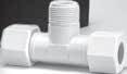
Brass Products SAE 45° Flare
A
Note: For additional technical questions, contact Technical Support at 1-888-258-0222.
Refer to safety information regarding proper selection of tubing and tube connectors on page 5.
Typical Application: LP and natural gas, flammable liquids (special order), instrumentation, refrigeration, power steering, hydraulic and pneumatic systems.
Pressure: Working pressure up to 2000 psi depending on tube size. Will withstand burst pressure of standard tubing - up to 5000 psi with bundyweld (double flared) and 3500 psi with copper tubing, depending on size.
Vibration: Good resistance - use long nut when greater vibration resistance is required.
Temperature Range: -65°F to +250°F (-53°C to +121°C) range at maximum operating pressures.
Material:
CA360 Brass.
Used With: Copper, brass, aluminum and steel hydraulic tubing that can be flared. See pages 25-29 for material compatibility.
Advantages: Low cost and reusability, long or short nut. Good resistance to vibration.
Conformance: Listed by Underwriter’s Laboratories (available on special order) for flammable liquids, refrigeration and gas. Meets specifications and standards of ASA, ASME, SAE and MS (Military Standards).
How to Order: Order individually by catalog number.
Note: Refer to current price list for availability of cataloged items. Configurations and dimensions subject to change without notice. Quotations of non-stock items available upon request. Additional information can be found in SAE J512.
Assembly Instructions:
1. Cut tubing to desired length. Make sure all burrs are removed and the ends are cut square.
2. Slide nut on tube. Threaded end “A” of nut must face out.
3. Flare end of tube with a 45° flaring tool. See page 23 for flare data.
a. Measure flare diameter
b. Examine flare for excessive thin out.
4. Lubricate threads and assemble to connector body. Nut should be turned hand tight.
5. Tighten assembly with a wrench until a solid feeling is encountered. From that point, apply a onesixth turn.
Note:
Do not over-torque as it may damage the connector or split the tubing at the flare.
Label Set: W-8022 (adhesive) CL-490 (non-adhesive)
41
Thread Size - B
Tube O.D. 1/8 3/16 1/4 5/16 3/8 7/16 1/2 5/8 3/4 Thread 5/16-24 3/8-24 7/16-20 1/2-20 5/8-18 11/16-18 3/4-16 7/8-14 1-1/16-14 Size-B
Page 40
Brass Products
SAE 45° Flare
Nut (Ref. SAE No. 010110)
Long Nut (Ref. SAE No. 010111)
Cap
Plug (Ref. SAE No. 010109)
Note: For additional technical questions, contact Technical Support at 1-888-258-0222.
Refer to safety information regarding proper selection of tubing and tube connectors on page 5.
Union (Ref. SAE No. 010101)
42 L D C L D C L D1 C L D C L C Tube Catalog O.D Number C D L 1/8 1110x2 3/8 .133 0.50 3/16 1110x3 7/16 .195 0.62 1/4 1110x4 9/16 .258 0.75 5/16 1110x5 5/8 .320 0.88 3/8 1110x6 3/4 .383 1.00 7/16 1110x7 13/16 .445 1.06 1/2 1110x8 7/8 .508 1.12 5/8 1110x10 1-1/16 .633 1.31 3/4 1110x12 1-1/4 .758 1.50 MTO - Made To Order Tube Catalog O.D. Number C D L 3/16 41x3 7/16 .195 0.81 1/4 41x4 9/16 .258 0.94 5/16 41x5 5/8 .320 1.12 3/8 41x6 3/4 .383 1.31 1/2 41x8 7/8 .508 1.62 5/8 41x10 1-1/16 .633 1.88 MTO - Made To Order Tube Catalog O.D. Number C L 1/8 40x2 7/16 0.40 3/16 40x3 1/2 0.47 1/4 40x4 7/16 0.53 5/16 40x5 5/8 0.62 3/8 40x6 3/4 0.69 1/2 40x8 7/8 0.84 5/8 40x10 1-1/16 0.97 3/4 40x12 1-5/16 1.09 Tube Catalog D1 O.D. Number C L (opt.) 1/8 39x2 5/16 0.47 .079 3/16 39x3 3/8 0.58 .126 1/4 39x4 7/16 0.69 .189 5/16 39x5 1/2 0.79 .220 3/8 39x6 5/8 0.88 .282 1/2 39x8 3/4 1.06 .408 5/8 39x10 7/8 1.19 .502 3/4 39x12 1-1/16 1.31 .627 Tube Catalog O.D Number C D L 1/8 42x2 5/16 .078 0.92 3/16 42x3 3/8 .125 1.06 1/4 42x4 7/16 .188 1.19 5/16 42x5 1/2 .219 1.34 3/8 42x6 5/8 .281 1.50 1/2 42x8 3/4 .406 1.81 5/8 42x10 7/8 .500 2.12 3/4 42x12 1-1/16 .625 2.44 MTO - Made To Order
Page 41
Brass Products
SAE 45° Flare
Male Connector (Ref. SAE No. 010102)
Female Connector (Ref. SAE No. 010103)
Male Ball Check Connector
43 D L C L D C L D D1 C Tube Male Pipe Catalog O.D Thread Number C D L 1/4 1/8 43x4 7/16 .125 1.06 3/8 1/4 43x6 5/8 .219 1.31 Tube Male Pipe Catalog O.D Thread Number D M N 1/4 1/8 54x4 .188 0.67 0.64 1/4 1/4 54x4x4 .188 0.73 0.87 5/16 1/8 54x5 .219 0.78 0.64 3/8 1/4 54x6 .283 0.89 0.86 1/2 3/8 54x8 .407 1.06 0.96 1/2 1/2 54x8x8 .406 1.12 1.17 5/8 3/8 54x10x6 .500 1.23 0.98 5/8 1/2 54x10 .500 1.23 1.17
45° Male Elbow (Ref. SAE No. 010302)
Tube Fem. Pipe Catalog O.D Thread Number C D L 3/16 1/8 46x3 9/16 .125 0.97 1/4 1/8 46x4 9/16 .188 1.03 1/4 1/4 46x4x4 11/16 .188 1.25 5/16 1/8 46x5 9/16 .219 1.06 5/16 1/4 46x5x4 11/16 .219 1.28 3/8 1/4 46x6 11/16 .281 1.31 3/8 3/8 46x6x6 13/16 .281 1.38 3/8 1/2 46x6x8 1 .281 1.62 1/2 3/8 46x8 13/16 .406 1.50 1/2 1/2 46x8x8 1 .406 1.75 5/8 3/8 46x10x6 7/8 .500 1.59 5/8 1/2 46x10w 1 .500 1.81 5/8 3/4 46x10x12 1-1/4 .500 1.90 MTO - Made To Order Tube Male Pipe Catalog O.D. Thread Number C D L1 D1 1/8 1/8 48x2 7/16 .078 0.90 .219 3/16 1/8 48x3 7/16 .125 1.00 .219 1/4 1/8 48x4 7/16 .188 1.06 .219 1/4 1/4 48x4x4 9/16 .188 1.26 .312 5/16 1/8 48x5 1/2 .219 1.16 .219 5/16 1/4 48x5x4 9/16 .219 1.34 .281 3/8 1/8 48x6x2 5/8 .281 1.25 .406 3/8 1/4 48x6 5/8 .281 1.44 .562 3/8 3/8 48x6x6 11/16 .281 1.44 .312 3/8 1/2 48x6x8 7/8 .281 1.69 .219 1/2 1/4 48x8x4 3/4 .406 1.62 .281 1/2 3/8 48x8 3/4 .406 1.62 .406 1/2 1/2 48x8x8 7/8 .406 1.81 .562 5/8 3/8 48x10x6 7/8 .500 1.81 .406 5/8 1/2 48x10 7/8 .500 2.00 .500 3/4 1/2 48x12 1-1/16 .562 2.18 .562 3/4 3/4 48x12x12 1-1/16 .625 2.18 .751
Page 42
Ball & Spring position may be reversed to change flow/check direction. Min pressure 3 psi.
Brass Products
SAE 45° Flare
44 D L C Tube SAE Tube Catalog Size Size Number C D L 1/4 1/4 1521 7/16 .188 1.094 SAE Tube Inverted Catalog Size Male Number C D L 1/4 3/16 1518 7/16 .189 1.031 1/4 1/4 1522 7/16 .188 1.031 3/8 5/16 1553 5/8 .234 1.340 3/8 3/8 1563 5/8 .282 1.380 3/8 7/16 1554 11/16 .282 1.400 Tube Catalog O.D. Number D M 1/2 55x8 .406 1.23 3/4 55x12 .625 1.64 MTO - Made To Order AC Type Adapter Adapter SAE 45° Flare to Inv. Flare 90° Union Elbow (Ref. SAE No. 010201) Tube Male Pipe Catalog O.D. Thread Number D D1 M N 1/8 1/8 49x2 .078 .219 0.62 0.69 3/16 1/8 49x3 .125 .219 0.75 0.75 1/4 1/8 49x4 .188 .219 0.81 0.76 1/4 1/4 49x4x4 .188 .312 0.88 0.99 1/4 3/8 49x4x6 .188 .406 0.94 1.03 5/16 1/8 49x5 .219 .219 0.91 0.78 5/16 1/4 49x5x4 .219 .312 0.95 0.92 3/8 1/8 49x6x2 .283 .219 1.03 0.91 3/8 1/4 49x6 .281 .312 0.97 1.06 3/8 3/8 49x6x6 .281 .406 1.06 1.09 3/8 1/2 49x6x8 .281 .438 1.16 1.28 1/2 1/4 49x8x4 .406 .312 1.23 1.19 1/2 3/8 49x8 .406 .406 1.23 1.12 1/2 1/2 49x8x8 .406 .406 1.25 1.32 5/8 3/8 49x10x6 .502 .406 1.42 1.23 5/8 1/2 49x10 .502 .562 1.42 1.37 3/4 1/2 49x12 .626 .562 1.62 1.48 3/4 3/4 49x12x12 .625 .750 1.59 1.62 Tube Fem. Pipe Catalog O.D Thread Number D M N 1/4 1/8 50x4 .189 0.88 0.47 1/4 1/4 50x4x4 .188 0.97 0.66 3/8 1/4 50x6 .283 1.09 0.69 MTO -
To Order
Made
90° Male Elbow (Ref. SAE No. 010202)
90° Female Elbow (Ref. SAE No. 010203)
Page 43
Brass Products
SAE 45° Flare
45 D D1 N N1 M Union
Male
Male
Adapter
(Female
Male Pipe
Tube Catalog O.D. Number D M 3/16 44x3 .125 0.73 1/4 44x4 .188 0.88 3/8 44x6 .283 1.06 1/2 44x8 .407 1.20 MTO - Made To Order Tube Male Pipe Catalog D1 O.D. Thread Number D Opt. M N 1/4 1/8 51x4 .188 .219 0.88 0.76 MTO - Made To Order Male Tube Pipe Catalog O.D. Thread Number D D1 M N 1/4 1/8 45x4 .188 .222 0.83 0.78 3/8 3/8 45x6x6x6 .283 .406 1.06 1.09 1/2 3/8 45x8 .407 .406 1.22 1.12 1/2 1/2 45x8x8x8 .406 .562 1.28 1.38 MTO - Made To Order Male Tube Pipe Catalog O.D Thread Number D D1 M N N1 1/4 1/8 56x4w .188 .188 0.78 0.76 0.46 MTO - Made To Order
Tee (Ref. SAE No. 010401)
Run Tee (Ref. SAE No. 010424)
Branch Tee (Ref. SAE No. 010425)
Tee
to
on Run)
Page 44
Brass Products Compression
Typical Application: Instrumentation, hydraulic and pneumatic systems.
Pressure: Working pressure up to 2000 psi with a 4:1 safety factor depending on tube size. When using plastic tubing, use the working pressure for type used.
Vibration:
Fair resistance - use long nut when greater vibration resistance is needed.
Temperature Range: 65°F to +250°F (-53°C to +121°C) with metal tubing. When using compatible plastic tubing do not exceed the tubing temperature range. (Refer to tubing temperature range.)
Material: CA360 Brass.
Used With: Aluminum, copper and plastic tubing.
Plastic tubing, except for PT230 and TP160, requires 2030x insert. Not recommended for steel tubing.
See pages 25-29 for material compatibility, and pages 30-33 for plastic tubing.
Note: For additional technical questions, contact Technical Support at 1-888-258-0222.
Refer to safety information regarding proper selection of tubing and tube connectors on page 5.
Advantages: Low cost. Easy to assemble, no flaring. Available with long or short nut. Broad selection of styles and sizes.
Conformance: Meets specifications and standards of ASA, ASME and SAE.
How to Order: Compression connectors are ordered as complete assemblies (body, nut and sleeve). To order assembly supplied with long nuts, simply add the prefix “1” to the catalog number. Example: 68x4 with long nut becomes 168x4. Nuts and sleeves can be ordered separately by catalog number. To order bodies only (less nut and sleeve). prefix catalog number with letter “B”. Example: B68x4. Note: Refer to current price list for availability of cataloged items. Quotations and delivery of non-stock items supplied on request. Configurations and dimensions subject to change without notice. Additional information can be found in SAE J512.
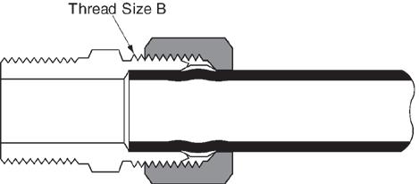
Assembly Instructions:
1. Cut tubing to desired length.
2. Slide nut and then sleeve on tube. Threaded end “A” of nut must face toward connector.
3. Insert tubing into connector body. Be sure tubing is bottomed on connector shoulder.
4. Lubricate threads and assemble nut to connector body.
5. Tighten nut hand tight. From that point, tighten with a wrench the number of turns indicated in the chart below.
Label Set:
W-8022 (adhesive)
CL-490 (non-adhesive)
46 A
Tube O.D. 1/8 3/16 1/4 5/16 3/8 7/16 1/2 5/8 3/4 1 Thread 5/16-24 3/8-24 7/16-24 1/2-24 9/16-24 5/8-24 11/16-20 13/16-18 1-18 1-1/4-18 Size-B Tube Additional turns Size From Hand Tight 1/8" thru 1/4" 1-1/4 5/16" 1-3/4 3/8" thru 1" 2-1/4 Thread Size B
Page 45
Brass Products Compression
H and H1 are hand tight dimensions.
Use only with PT200 and PT240 Tubing.
No. 060115)
* For Tubing with .126 I.D./.062 wall thickness.
** For tubing with .170 I.D./.040 wall thickness.
SAE No. 060110)
47 E E H1 H D AB C L D F L D C Tube E Tube Stop O.D. Depth H H1 (Long Nut) 1/8 0.19 0.23 –3/16 0.22 0.25 0.47 1/4 0.25 0.29 0.56 5/16 0.28 0.30 0.66 3/8 0.31 0.27 0.70 1/2 0.38 0.42 0.88 5/8 0.38 0.42 0.92 3/4 0.44 0.49 1.18 Tube Catalog DIA. DIA. DIA. Length O.D. Number A B C D 1/4 2030x4* 1/8 3/32 11/64 19/32 1/4 2030x44** 11/64 9/64 7/32 17/32 5/16 2030x5 3/16 5/32 15/64 5/8 3/8 2030x6 1/4 7/32 11/32 41/64 1/2 2030x8 3/8 11/32 7/16 13/16 5/8 2030x10 1/2 29/64 35/64 13/16 3/4 2030x12 9/16 33/64 11/16 1-1/32
Tube Catalog O.D Number D F L 1/8 60x2 0.13 0.19 0.19 3/16 60x3 0.19 0.27 0.22 1/4 60x4 0.26 0.34 0.25 5/16 60x5 0.32 0.41 0.25 3/8 60x6 0.38 0.47 0.25 7/16 60x7 0.44 0.53 0.31 1/2 60x8 0.51 0.59 0.38 5/8 60x10 0.63 0.72 0.38 3/4 60x12 0.76 0.88 0.44 MTO - Made To Order Tube Catalog O.D Number C D L 1/8 61x2 3/8 0.13 0.38 3/16 61x3 7/16 0.19 0.41 1/4 61x4 1/2 0.26 0.44 5/16 61x5 9/16 0.32 0.44 3/8 61x6 5/8 0.38 0.47 7/16 61x7 11/16 0.44 0.50 1/2 61x8 13/16 0.51 0.62 5/8 61x10 15/16 0.63 0.62 5/8 61x12 1-3/16 0.76 0.69 MTO - Made To Order
Tube
Compression Sleeve (Ref. SAE
Nut (Ref.
E E H1 H
Support for Plastic Tubing
Page 46
Brass Products Compression
Long Nut (Ref. SAE No. 060111)
Used on 74x Bulkhead Unions. Ref. page 49.
Bulkhead Nut Union (Ref. SAE No. 060101BA)
Assembly
Male Connector (Ref. SAE No. 060102BA)
Assembly with long nut 168x.
48 L D C L C L D C L D C Tube Catalog Thread O.D. Number C L size 1/4 0102x4 9/16 0.25 7/16–24 3/8 0102x6 11/16 0.25 9/16–24 1/2 0102x8 15/16 0.38 11/16–20 Tube Catalog O.D Number C D L 1/8 62x2 5/16 .094 0.66 3/16 62x3 3/8 .125 0.76 1/4 62x4 7/16 .188 0.79 5/16 62x5 1/2 .250 0.88 3/8 62x6 9/16 .312 0.97 1/2 62x8 11/16 .406 1.10 5/8 62x10 13/16 .500 1.25 3/4 62x12 1 .562 1.44 MTO - Made To Order Tube Male Pipe Catalog D1 O.D. Thread Number C D OPT. L 1/8 1/16 68x2x1 3/8 .094 – 0.78 1/8 1/8 68x2 7/16 .094 .094 0.78 3/16 1/8 68x3 7/16 .125 .125 0.84 1/4 1/8 68x4 7/16 .188 .188 0.88 1/4 1/4 68x4x4 9/16 .188 .312 1.06 5/16 1/8 68x5 1/2 .250 .234 0.91 5/16 1/4 68x5x4 9/16 .250 .250 1.09 3/8 1/8 68x6x2 9/16 .312 .250 0.97 3/8 1/4 68x6 9/16 .312 .312 1.17 3/8 3/8 68x6x6 11/16 .312 .312 1.16 3/8 1/2 68x6x8 7/8 .312 .562 1.34 1/2 1/4 68x8x4 11/16 .406 .281 1.22 1/2 3/8 68x8 11/16 .406 .406 1.22 1/2 1/2 68x8x8 7/8 .406 .406 1.41 5/8 1/2 68x10 7/8 .500 .500 1.50 3/4 1/2 68x12 1 .562 .562 1.62 3/4 3/4 68x12x12 1-1/16 .562 .875 1.62 MTO
Order Tube Catalog O.D. Number C D L 3/16 1611x3 7/16 .193 0.62 1/4 1611x4 9/16 .260 0.75 5/16 1611x5 5/8 .320 0.84 3/8 1611x6 11/16 .380 0.88 1/2 1611x8 13/16 .510 1.06 5/8 1611x10 15/16 .637 1.08 3/4 1611x12 1-1/8 .760 1.38 MTO - Made To Order
- Made To
with long nut 162x. Not available in the x3 style.
Page 47
Brass Products Compression
Female Connector (Ref. SAE No. 060103BA)
Assembly with long nut 166x.
Male Ball Check Connector
Assembly with long nut 163x. Min. working pressure 3 psi. Ball and spring position may be reversed to change flow/check direction. Ball check valves are neither tested nor adjusted prior to sale.
Bulkhead Union
Assembly with long nut 174x. For Bulkhead Nuts, ref. page 48, included with assembly.
49 L D C L D C L D P C Tube Fem. Pipe Catalog O.D. Thread Number C D L 1/8 1/8 66x2 9/16 .094 0.75 3/16 1/8 66x3 9/16 .125 0.78 1/4 1/8 66x4 9/16 .188 0.78 1/4 1/4 66x4x4 11/16 .188 1.03 5/16 1/8 66x5 9/16 .250 0.81 5/16 1/4 66x5x4 11/16 .250 1.03 3/8 1/8 66x6x2 9/16 .312 0.84 3/8 1/4 66x6 11/16 .312 1.06 1/2 3/8 66x8 13/16 .406 1.12 MTO - Made To Order Tube Male Pipe Catalog O.D Thread Number C D L 1/4 1/8 63x4 7/16 .125 0.88 3/8 1/4 63x6 9/16 .219 1.16 Tube Catalog Max. O.D Number C D L P 1/4 74x4 9/16 .188 1.57 0.52 3/8 74x6 11/16 .312 1.76 0.55 MTO - Made To Order
Page 48
Brass Products
Compression
90° Male Elbow (Ref. SAE No. 060202BA)
90°
50 Tube Male Pipe Catalog O.D. Thread Number D D1 M N 1/8 1/16 69x2x1 .104 .125 0.54 0.66 1/8 1/8 69x2 .094 .219 0.60 0.67 3/16 1/8 69x3 .125 .219 0.62 0.69 1/4 1/8 69x4 .188 .219 0.62 0.75 1/4 1/4 69x4x4 .188 .188 0.63 0.84 5/16 1/8 69x5 .250 .234 0.62 0.75 5/16 1/4 69x5x4 .202 .344 0.69 0.84 3/8 1/8 69x6x2 .312 .234 0.69 0.69 3/8 1/4 69x6 .312 .344 0.75 0.93 3/8 3/8 69x6x6 .312 .437 0.85 0.94 3/8 1/2 69x6x8 .312 .562 1.04 1.14 7/16 1/4 69x7 .312 .312 0.84 1.00 1/2 1/4 69x8x4 .406 .312 0.84 0.94 1/2 3/8 69x8 .406 .407 0.94 1.12 1/2 1/2 69x8x8 .406 .531 0.94 1.31 5/8 1/2 69x10 .500 .564 1.06 1.31 3/4 1/2 69x12 .562 .562 1.19 1.50 3/4 3/4 69x12x12 .562 .562 1.19 1.31 MTO - Made To Order
Tube Catalog O.D Number D M 1/4 65x4 .188 0.60 5/16 65x5 .250 0.62 3/8 65x6 .312 0.75 1/2 65x8 .406 0.94 Tube Fem. Pipe Catalog O.D Thread Number D M N 3/16 1/8 70x3 .125 0.69 0.56 1/4 1/8 70x4 .188 0.69 0.56 3/8 1/4 70x6 .312 0.81 0.75 1/2 3/8 70x8 .406 1.00 0.88 MTO - Made To Order
Union Elbow (Ref. SAE No. 060201BA)
90° Female Elbow (Ref. SAE No. 060203BA)
Assembly with long nut 169x. Assembly with long nut 165x. Assembly with long nut 170x.
Page 49
Brass Products Compression
with long nut 164x. Assembly with long nut 171x. Assembly with long nut 172x.
to Male Pipe on
51 D1 D N1 N M Tube Catalog O.D. Number D M 3/16 64x3 .125 0.60 1/4 64x4 .188 0.62 5/16 64x5 .250 0.67 3/8 64x6 .312 0.73 1/2 64x8 .406 0.94 Union Tee (Ref. SAE No. 060401BA) Tube Male Pipe Catalog O.D Thread Number D D1 M N 3/16 1/8 71x3 .125 .219* 0.64 0.68 1/4 1/8 71x4 .188 .219* 0.63 0.75 3/8 1/4 71x6 .312 .344* 0.75 0.94 *Optional Counterbore. Male Run Tee (Ref. SAE No. 060424BA) Tube Male Pipe Catalog O.D Thread Number D D1 M N 3/16 1/8 72x3 .125 .219 0.62 0.69 1/4 1/8 72x4 .188 .219 0.63 0.74 1/4 1/4 72x4x4x4 .188 .281 0.78 0.85 5/16 1/8 72x5 .250 .234 0.66 0.70 3/8 1/4 72x6 .312 .344 0.78 0.91 1/2 3/8 72x8 .406 .406 0.96 1.08 MTO - Made To Order Male Branch Tee (Ref. SAE No. 060425BA) Tube M&F Pipe Catalog O.D. Thread Number D D1 M N N1 1/4 1/8 76x4 .188 .219 0.59 0.63 0.47 MTO - Made To Order Adapter
Tee (Female
Run) Assembly
Page 50
Brass Products SelfAlign
Note: For additional technical questions, contact Technical Support at 1-888-258-0222.
B A
Refer to safety information regarding proper selection of tubing and tube connectors on page 5.
Typical Application: Instrumentation, hydraulic and pneumatic systems.
Pressure: Working pressure up to 2000 psi with a 4:1 safety factor depending on tube size. When using plastic tubing, use the working pressure for type used.
Vibration: Good resistance - use long nut when greater vibration resistance is needed.
Temperature Range:
-65°F to +250°F (-53°C to +121°C) with metal tubing. When using compatible plastic tubing do not exceed the tubing temperature range. (Refer to tubing temperature range.)
Material:
CA360 Brass.
Used with: Aluminum, copper and plastic tubing.
Plastic tubing, except for PT230 and TP160, requires 2030x insert. Not recommended for steel tubing. See pages 25-29 for material compatibility, and pages 30-33 for plastic tubing.
Advantages: Very low cost and reusable. Self aligning - no need to disassemble fitting to line up sleeve on tube. Low cost. Easy to assemble, no flaring. Available with long or short nut. Broad selection of styles and sizes.
Conformance: An exclusive product design, user approvals only.
How to Order: Selfalign connectors are ordered as complete assemblies (body, nut and sleeve). To order assembly supplied with long nuts, simply add the prefix “1” to the catalog number. Example: 681x4 with long nut becomes 1681x4. Nuts and sleeves can be ordered separately by catalog number. To order bodies only (less nut and sleeve), prefix catalog number with the letter “B” and drop suffix number.
Example: B68x4.
Note: Refer to current price list for availability of cataloged items. Quotations and delivery of non-stock items supplied on request. Configurations and dimensions subject to change without notice.
Assembly Instructions:
1. Cut tubing to desired length.
2. Slide nut and then sleeve on tube. Threaded end of nut “A” and small end of sleeve “B” must face toward fitting.
3. Insert tubing into connector body. Be sure tubing is bottomed on connector shoulder.
4. Lubricate threads and assemble nut to connector body
5. Tighten with wrench to the “ring grip” point.
a. Ring Grip is the point when the cutting edge of the sleeve grips the tube. This is determined by turning tube slowly but firmly by hand while tightening the nut with a wrench until tube can no longer be turned by hand and a sharp increase in torque is noticed.
6. Tighten additional turns past “ring grip” as indicated on chart. Refer to page 53.
Label Set: CL-500 (non-adhesive)
52 Tube O.D. 1/8 3/16 1/4 5/16 3/8 7/16 1/2 5/8 3/4 1 Thread 5/16-24 3/8-24 7/16-24 1/2-24 9/16-24 5/8-24 11/16-20 13/16-18 1-18 1-1/4-18 Size-B
Size B
Thread
Page 51
Brass Products SelfAlign
Ring Grip is the point when the cutting edge of the sleeve grips the tube. This is determined by turning tube slowly but firmly by hand while tightening the nut with a wrench until tube can no longer be turned by hand and a sharp increase in torque is noted.
SelfAlign Assembly Data Chart
Annealed
H and H1 are hand tight dimensions.
53 E E H H1 Tube E Tube Stop H H1 O.D. Depth (Std. Nut) (Long Nut) 1/8 0.19 0.24 –3/16 0.22 0.25 0.49 1/4 0.25 0.35 0.61 5/16 0.28 0.30 0.70 3/8 0.31 0.31 0.75 1/2 0.38 0.36 0.83 5/8 0.38 0.41 0.92 3/4 0.44 0.41 1.14
Selfalign fitting used with soft plastic tubing and brass insert.
Assembly Comparison
Selfalign fitting used on rigid plastic tubing, no insert.
Nut
Copper and Soft Aluminum Tubing Nylon Tubing Type “T” Type “H” Fitting Thin Wall Thick Wall Size Wall Turns* Wall Turns* Wall Turns* 2 .030 1-1/3 – – – –3 .030 1-1/3 .023 1-2/3 .039 1-1/3 4 .030 1-2/3 .030 2 .050 1-2/3 5 .032 1-2/3 .036 1-2/3 .062 2-2/3 6 .032 2 .040 1-2/3 .075 2 8 .032 2 – – – –10 .035 2 – – – –12 .049 2 – – – –16 .065 2-1/4 – – – –*Turns from “Ring Grip” E E H H1
SelfAlign Assembly Page 52
Brass Products SelfAlign
Tube Supports for Plastic
Use only with PT200 and PT240 Tubing.
Use on 741x Bulkhead Unions. Ref. page 56.
54 D AB C L D F L D C L D C L C Tube Catalog Dia. Dia. Dia. Length O.D. Number A B C D 1/4 2030x4* 1/8 3/32 11/64 19/32 1/4 2030x44** 11/64 9/64 7/32 17/32 5/16 2030x5 3/16 5/32 15/64 5/8 3/8 2030x6 1/4 7/32 11/32 41/64 1/2 2030x8 3/8 11/32 7/16 13/16 5/8 2030x10 1/2 29/64 35/64 13/16 3/4 2030x12 9/16 33/64 11/16 1-1/32 *For tubing with .126 I.D./.062 wall. **For tubing with .170 I.D./.040 wall. Tube Catalog O.D. Number D F L 1/8 601x2 0.130 0.25 0.20 3/16 601x3 0.193 0.31 0.20 1/4 601x4 0.256 0.38 0.26 5/16 601x5 0.318 0.44 0.26 3/8 601x6 0.381 0.50 0.26 1/2 601x8 0.507 0.62 0.30 5/8 601x10 0.630 0.72 0.36 3/4 601x12 0.755 0.88 0.38 1 601x16 1.005 1.19 0.50 Tube Catalog O.D Number C D L 1/8 611x2 3/8 0.14 0.38 3/16 611x3 7/16 0.19 0.38 1/4 611x4 1/2 0.26 0.44 5/16 611x5 9/16 0.32 0.44 3/8 611x6 5/8 0.38 0.44 1/2 611x8 13/16 0.51 0.52 5/8 611x10 15/16 0.64 0.56 Tube Catalog O.D. Number C D L 3/16 1611x3 7/16 .193 0.62 1/4 1611x4 9/16 .260 0.75 3/8 1611x6 11/16 .380 0.88
Tubing Sleeve Nut Long Nut
Tube Catalog O.D Number C L 1/4 0102x4 9/16 .25 3/8 0102x6 11/16 .25 1/2 0102x8 15/16 .38 Bulkhead Nut
Page 53
Brass Products SelfAlign
55 L D I C L D C L D C L D C Tube Catalog O.D. Number C D I L 1/8 621x2 5/16 .094 0.25 0.66 3/16 621x3 3/8 .125 0.28 0.76 1/4 621x4 7/16 .188 0.31 0.79 5/16 621x5 1/2 .250 0.34 0.88 3/8 621x6 9/16 .312 0.38 0.97 1/2 621x8 11/16 .406 0.44 1.10 5/8 621x10 13/16 .500 0.50 1.25 Tube Male Pipe Catalog O.D Thread Number C D L 1/8 1/16 681x2x1 3/8 .094 0.78 1/8 1/8 681x2 7/16 .094 0.78 3/16 1/8 681x3 7/16 .125 0.84 1/4 1/8 681x4 7/16 .188 0.88 1/4 1/4 681x4x4 9/16 .188 1.06 5/16 1/8 681x5 1/2 .234 0.91 5/16 1/4 681x5x4 9/16 .250 1.09 3/8 1/8 681x6x2 9/16 .250 0.97 3/8 1/4 681x6 9/16 .312 1.17 3/8 3/8 681x6x6 11/16 .312 1.16 3/8 1/2 681x6x8 7/8 .312 1.34 1/2 1/4 681x8x4 11/16 .281 1.22 1/2 3/8 681x8 11/16 .406 1.22 1/2 1/2 681x8x8 7/8 .406 1.41 5/8 1/2 681x10 7/8 .500 1.50 Union Male Connector Assembly with long nut 1621x. Assembly with long nut 1681x. Tube Fem. Pipe Catalog O.D. Thread Number C D L 1/8 1/8 661x2 9/16 .094 0.75 3/16 1/8 661x3 9/16 .125 0.78 1/4 1/8 661x4 9/16 .188 0.78 1/4 1/4 661x4x4 11/16 .188 1.03 5/16 1/8 661x5 9/16 .250 0.81 3/8 1/8 661x6x2 9/16 .312 0.84 3/8 1/4 661x6 11/16 .312 1.06 1/2 3/8 661x8 13/16 .406 1.12 Tube Male Pipe Catalog O.D Thread Number C D L 1/4 1/8 631x4 7/16 .125 0.88 3/8 1/4 631x6 9/16 .219 1.16 Female Connector
Assembly with long nut 1661x.
Male Ball Check Connector
Assembly with long nut 1631x. Min. pressure 3 psi. Ball and spring position may be reversed to change flow/check direction. Ballcheck valves are neither tested nor adjusted prior to sale.
Page 54
56 L D P I C Tube Catalog O.D. Number C D I L Max. P 1/4 741x4 9/16 .188 0.33 1.58 0.52 Tube Catalog O.D Number D M 1/4 651x4 .188 0.60 3/8 651x6 .312 0.75
Bulkhead Union 90° Union Elbow Tube Male Pipe Catalog O.D Thread Number D D1 M N 1/8 1/16 691x2x1 .109 .125 0.54 0.66 1/8 1/8 691x2 .094 .219 0.60 0.67 3/16 1/8 691x3 .125 .188 0.62 0.69 1/4 1/8 691x4 .188 .219 0.62 0.75 1/4 1/4 691x4x4 .188 .219 0.63 0.84 5/16 1/8 691x5 .250 .250 0.62 0.75 5/16 1/4 691x5x4 .250 .344 0.69 0.84 3/8 1/8 691x6x2 .312 .235 0.69 0.69 3/8 1/4 691x6 .312 .344 0.75 0.93 3/8 3/8 691x6x6 .312 .437 0.85 0.94 3/8 1/2 691x6x8 .312 .562 1.04 1.14 1/2 1/4 691x8x4 .406 .312 0.84 0.94 1/2 3/8 691x8 .406 .407 0.94 1.12 1/2 1/2 691x8x8 .406 .531 0.94 1.31 5/8 1/2 691x10 .500 .564 1.06 1.31 Tube Fem. Pipe Catalog O.D Thread Number D M N 3/16 1/8 701x3 .125 0.69 0.56 1/4 1/8 701x4 .188 0.69 0.56
Assembly with long nut 1741x. Assembly with long nut 1651x.
90° Male Elbow
90° Female Elbow Assembly with long nut 1701x.
Assembly with long nut 1691x.
Page 55
Brass Products SelfAlign
Brass Products
SelfAlign
57 Tube Catalog O.D. Number D M 3/16 641x3 .125 0.60 1/4 641x4 .188 0.62 5/16 641x5 .250 0.67 3/8 641x6 .312 0.73 1/2 641x8 .406 0.94 Union Tee Assembly with long nut 1641x. Tube Male Pipe Catalog D1 O.D Thread Number D Opt. M N 3/16 1/8 711x3 .125 .219 0.62 0.69 1/4 1/8 711x4 .188 .219 0.63 0.75 3/8 1/4 711x6 .312 .344 0.75 0.94 Tube Male Pipe Catalog O.D. Thread Number D D1 M N 1/4 1/8 721x4 .188 .219 0.63 0.74 1/4 1/4 721x4x4x4 .188 .281 0.78 0.85 3/8 1/4 721x6 .312 .344 0.75 0.94 1/2 3/8 721x8 .406 .406 0.94 1.12 Male Run Tee Male Branch Tee Assembly with long nut 1711x. Assembly with long nut 1721x.
Page 56
Brass Products
Polyline Flareless
Typical Application: Pneumatic instrumentation circuits, lubricant and cooling lines.
Pressure: Working pressure up to 500 psi with a 4:1 safety factor depending on tubing. When using plastic tubing, use the working pressure for type used.
Vibration: Excellent resistance.
Temperature Range: When using compatible plastic tubing do not exceed the tubing temperature range. (Refer to tubing temperature range.)
Material: CA360 Brass body, plastic sleeve.
Note: Not recommended for use with PT230, TP160 or Air Brake tubing.
Used With: PT200 and PT240 plastic tubing. Not recommended for metal tubing. See pages 25-29 for material compatibility and pages 30-33 for plastic tubing.
Advantages: No flaring of tubing required. Easy installation, captive sleeve, pre-assembled for installation and can be reassembled.
Conformance: An exclusive product design. User approvals only.
How to Order: Order 1/4" O.D. tubing with .040 wall, use suffix x4. Example: 1262x4. When .062 wall is desired, use suffix x46. Example: 1262x46. Ordered as complete assemblies (body, nuts and sleeves) by catalog number. Nuts, sleeves and nut/sleeve assemblies can be ordered separately by catalog number.
Refer to safety information regarding proper selection of tubing and tube connectors on page 5.
Note: Refer to current price list for availability of cataloged items. Quotations and delivery of non-stock items supplied on request. Configurations and dimensions subject to change without notice.
Assembly Instructions:
1. Cut tubing to desired length.
2. Slide nut/sleeve assembly on tube. Threaded end “A” of nut must face toward connector.
3. Bottom tubing into the connector.
4. Tighten nut, hand tight.
Label Set: FS-2100 (adhesive) CL-498 (non-adhesive)
Questions: For additional technical questions, contact Technical Support at 1-888-258-0222.
58 A Thread Size B D1D2
Size x46 x4 x5 x6 x8 Tube O.D. 1/4 1/4 5/16 3/8 1/2 Thread Size-B 3/8–24 3/8–24 7/16–24 1/2–24 11/16–20 Flow Dia. (D1) .078 .125 .141 .203 .312 Support Dia. (D2) .120 .166 .180 .245 .370
Page 57
Brass Products Polyline Flareless
59 L C L C C L Tube Catalog O.D. Number C L 1/4 1260x4 .259 0.34 5/16 1260x5 .321 0.39 3/8 1260x6 .384 0.41 1/2 1260x8 .509 0.44 Tube Catalog Dia. O.D Number C L 1/4 1261x4 7/16 0.34 5/16 1261x5 1/2 0.34 3/8 1261x6 9/16 0.38 1/2 1261x8 13/16 0.44 MTO - Made To Order Plastic Sleeve Brass Nut 1/8" and 3/16" Nuts are flat Hex type. Tube Catalog Dia. O.D Number C L 1/4 1261x4A 7/16 0.43 5/16 1261x5A 1/2 0.45 3/8 1261x6A 9/16 0.49 1/2 1261x8A 13/16 0.46 MTO - Made To Order Brass Nut/Plastic Sleeve Assembly Tube Catalog O.D. Number C L 1/4 1202x4 9/16 0.19 3/8 1202x6 11/16 0.19 1/2 1202x8 7/8 0.19 MTO - Made To Order Brass Bulkhead Nut For use with 1274x Bulkhead Unions, ref. page 60. Tube Catalog O.D Number C L L1 1/4 1262x4 3/8 1.00 0.69 3/8 1262x6 1/2 1.03 0.72 1/2 1262x8 11/16 1.28 0.84 MTO - Made To Order Union L C L1 L C
Page 58
Brass Products
Polyline Flareless
60 Tube Male Pipe Catalog O.D. Thread Number C L L1 1/4 1/16 1268x4x1 7/16 0.97 0.81 1/4 1/8 1268x4 7/16 0.97 0.81 1/4 1/4 1268x4x4 9/16 1.15 1.00 1/4 3/8 1268x4x6 11/16 1.18 1.03 5/16 1/8 1268x5w 7/16 0.97 0.81 5/16 1/4 1268x5x4 9/16 1.16 1.00 3/8 1/8 1268x6x2 1/2 1.00 0.84 3/8 1/4 1268x6 9/16 1.19 1.03 3/8 3/8 1268x6x6 11/16 1.19 1.03 1/2 1/4 1268x8x4 11/16 1.31 1.09 1/2 3/8 1268x8 11/16 1.31 1.09 1/2 1/2 1268x8x8 11/16 1.62 1.03 MTO - Made To Order Male Connector L1 L C Tube Fem. Pipe Catalog O.D Thread Number C L L1 1/4 1/8 1266x4 1/2 0.87 0.72 1/4 1/4 1266x4x4 5/8 1.09 0.93 3/8 1/4 1266x6 5/8 1.09 0.94 Female Connector Tube Catalog Max. O.D. Number C L L1 P 1/4 1274x4 9/16 1.56 1.25 0.38 3/8 1274x6 11/16 1.68 1.38 0.47 1/2 1274x8 7/8 2.09 1.66 0.63 MTO - Made To Order Bulkhead Union For Bulkhead Nuts, ref. page 59. L1 L P C L1 L C
Page 59
Brass Products
Polyline Flareless
61 Tube Male Pipe Catalog O.D. Thread Number M M1 N 1/4 1/16 1269x4x1 0.75 0.59 0.72 1/4 1/8 1269x4 0.75 0.59 0.72 1/4 1/4 1269x4x4 0.81 0.66 0.94 1/4 3/8 1269x4x6 0.84 0.69 1.08 5/16 1/8 1269x5 0.75 0.59 0.72 3/8 1/8 1269x6x2 0.86 0.72 0.75 3/8 1/4 1269x6 0.86 0.72 0.92 3/8 3/8 1269x6x6 0.86 0.72 1.08 MTO - Made To Order Male Elbow Tube Fem. Pipe Catalog O.D. Thread Number M M1 N 1/4 1/8 1270x4 0.81 0.71 0.56 1/4 1/4 1270x4x4 0.96 0.75 0.69 3/8 1/4 1270x6 0.86 0.75 0.69 MTO - Made To Order Female Elbow M M M1 M1 N Tube Catalog O.D Number M M1 N N1 1/4 1264x4 0.75 0.59 0.75 0.59 3/8 1264x6 0.87 0.72 0.87 0.72 Union Tee Tube Male Pipe Catalog O.D. Thread Number M M1 N 1/4 1/8 1271x4 0.75 0.59 0.72 1/4 1/4 1271x4x4x4 0.81 0.66 0.94 3/8 1/4 1271x6 0.87 0.72 1.00 MTO - Made To Order Male Run Tee Tube Male Pipe Catalog O.D Thread Number M M1 N 1/4 1/8 1272x4 0.75 0.59 0.72 1/4 1/4 1272x4x4x4 0.81 0.66 0.94 3/8 1/4 1272x6 0.87 0.72 1.00 1/2 3/8 1272x8 1.06 0.84 1.12 MTO - Made To Order Male Branch Tee
Page 60
Brass Products
Push>Connect
Typical Application: Compressed air, pneumatic instrumentation, circuit, lubricant and cooling lines.
Pressure: Up to 250 psi depending on tube size.
Sealing Method: O-Ring of Buna-N Construction.
Temperature Range: When using compatible plastic tubing do not exceed the tubing temperature range (Refer to tubing temperature range).
Material: Brass, Nickel Plated.
Note: For additional technical questions, contact Technical Support at 1-888-258-0222.
Refer to safety information regarding proper selection of tubing and tube connectors on page 5.
Push>Connect Metric
Typical Application: Compressed air, pneumatic instrumentation, circuit, lubricant and cooling lines.
Pressure: Up to 250 psi depending on tube size.
Sealing Method: O-Ring of Buna-N Construction.
Temperature Range: -40°F to 200°F (-40°C to 93°C).
Material: Brass, Nickel Plated.
Used With: MTP160 nylon tubing. See pages 25-29 for material compatibility and pages 30-32 for plastic tubing.
Vacuum: Fittings rated at 29.5 inches of mercury vacuum.
Used With: PT230 and TP160 nylon, and PT240 Polyethylene tubing. See pages 25-29 for material compatibility and pages 30-33 for plastic tubing.
Advantages: Ease of assembly. No tools required, reusability of connectors and the time savings of assembly and disassembly.
Hex Dimensions: All hexes are in inches.
How to Order: Individually by catalog number.
Note: Refer to current price list for availability of cataloged items. Quotations and delivery of non-stock items supplied on request. Configurations and dimensions subject to change without notice.
Assembly Instructions:
1. To connect, simply push the tubing into the connector.
2. To disconnect, depress the collet ring with two fingers and withdraw.
Label Set: CL-499 (non-adhesive)
Advantages: Ease of assembly. No tools required, reusability of fittings and the time savings of assembly and disassembly.
Hex Dimensions: All hexes are metric. How to Order: Individually by catalog number.
Note: Refer to current price list for availability of cataloged items. Quotations and delivery of non-stock items supplied on request. Configurations and dimensions subject to change without notice.
Assembly Instructions:
1. To connect, simply push the tubing into the connector.
2. To disconnect, depress the collet ring with two fingers and withdraw.
Suffix Chart:
MM - Metric Screw Thread
MMS - Metric Screw Thread Swivel
MRP - Metric Red Plug
PP - British Parallel Plug
PPS - British Parallel Pipe Swivel
PT - British Tapered Pipe
PTS - British Tapered Pipe Swivel
62
See Push>Connect Products on pages 59-63.
Push>Connect
Nominal Size 2 4 5MM 6 8 Thread MM M5 x .8 BSPT 1/8 (2PT) 1/4 (4PT) 3/8 (6PT) 1/2 (8PT) BSPP 1/8 (2PP) 1/4 (4PP) 3/8 (6PP) 1/2
See Push>Connect Products on pages 64-67.
Page 61
Brass Products
Push>Connect
Push>Connect Flow Controls Typical Application: Compressed air, pneumatic instrumentation, circuit, lubricant and cooling lines. Also excellent for assembly equipment and cylinder control.
Pressure: Up to 250 psi depending on tube size.
Sealing Method: O-Ring of Buna-N Construction. (Viton available on request by special order.)
Temperature Range: 0°F to +160°F (-17.8°C to +71°C)
Material: Brass, Nickel Plated.
Note: For additional technical questions, contact Technical Support at 1-888-258-0222.
Refer to safety information regarding proper selection of tubing and tube connectors on page 5.
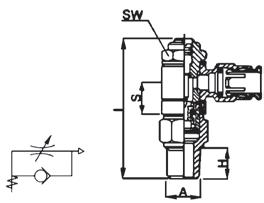
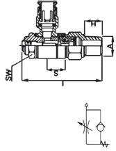
Used With: PT230 and TP160 nylon, and PT240 Polyethylene tubing. See pages 25-29 for material compatibility and pages 30-33 for plastic tubing.
Advantages:
Ease of assembly. No tools required, reusability of connectors and the time savings of assembly and disassembly. These flow controls have a simple design, but offer excellent ability to control the speed of a cylinder or motor.
Hex Dimensions: All hexes are in inches. How to Order: Individually by catalog number.
Note: Refer to current price list for availability of cataloged items. Quotations and delivery of non-stock items supplied on request. Configurations and dimensions subject to change without notice.
Assembly Instructions:
1. To connect, simply push the tubing into the connector.
2. To disconnect, depress the collet ring with two fingers and withdraw.
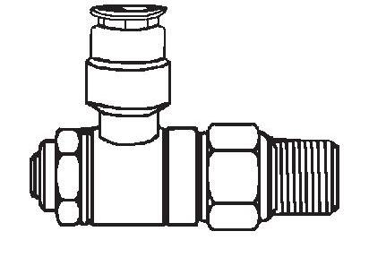
63
See
73-74. SW A H S L A H L
Push>Connect Products on pages
Page 62
Brass Products Push>Connect
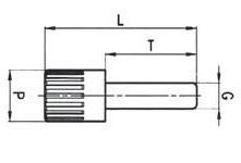
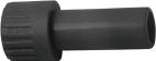
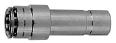
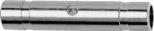
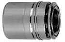
64 Tube Catalog O.D. Number F G L S H B 1/8 1161x2 0.34 0.35 0.59 .344 .433 0.14 5/32 1161x2.5 0.34 0.35 0.57 .344 .433 0.14 1/4 1161x4 0.46 0.48 0.65 .470 .472 0.16 5/16 1161x5 0.54 0.56 0.67 .549 .551 0.25 3/8 1161x6 0.62 0.64 0.79 .627 .590 0.32 1/2 1161x8 0.74 0.76 0.83 .746 .629 0.42 Cartridge G Tube Catalog O.D. Number L P T 1/8 1129x2 1.06 0.24 0.79 5/32 1129x2.5 1.14 0.32 0.79 1/4 1129x4 1.24 0.32 0.89 5/16 1129x5 1.36 0.47 0.96 3/8 1129x6 1.46 0.47 1.06 1/2 1129x8 1.59 0.63 1.12 Plug (Plastic) Tube Catalog O.D Number L 1/8 1105x2 1.28 5/32 1105x2.5 1.28 1/4 1105x4 1.40 5/16 1105x5 1.59 3/8 1105x6 1.81 1/2 1105x8 1.89 Double Union Tube Tube O.D. O.D. Catalog A B Number C F L T 1/8 1/4 1109x2x4 0.61 0.35 1.16 0.71 5/32 1/4 1109x2.5x4 0.61 0.35 1.16 0.71 1/4 3/8 1109x4x6 0.82 0.50 1.46 0.91 1/4 1/2 1109x4x8 0.68 0.50 1.32 0.91 3/8 1/2 1109x6x8 0.79 0.65 1.58 0.94 Reducer Joins Push>Connect Fittings. Cartridge body is not Nickel-plated. S H B F L G L A B L C T F L P G T
Page 63
Brass Products Push>Connect
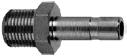


65 Catalog Tube Male Number O.D. Pipe Thread H T L SW (mm) 1/8 1/8 1180x2 0.37 0.65 1.20 12 1/8 1/4 1180x2x4 0.51 0.65 1.36 14 5/32 1/8 1180x2.5 0.37 0.65 1.20 12 5/32 1/4 1180x2.5x4 0.51 0.65 1.36 14 1/4 1/8 1180x4 0.37 0.71 1.26 12 1/4 1/4 1180x4x4 0.51 0.71 1.42 14 5/16 1/8 1180x5 0.37 0.81 1.36 12 5/16 1/4 1180x5x4 0.51 0.81 1.34 14 3/8 1/4 1180x6 0.51 0.91 1.61 17 3/8 3/8 1180x6x6 0.51 0.91 1.61 19 1/2 3/8 1180x8 0.51 0.94 1.65 19 1/2 1/2 1180x8x8 0.71 0.94 1.87 22 Stem Adapter Tube Catalog O.D Number F G L N 1/8 1162x2 0.33 0.35 1.14 0.55 5/32 1162x2.5 0.33 0.35 1.14 0.55 1/4 1162x4 0.46 0.47 1.32 0.64 5/16 1162x5 0.54 0.55 1.46 0.69 3/8 1162x6 0.61 0.66 1.61 0.79 1/2 1162x8 0.72 0.75 1.71 0.83 Union Tube Catalog MAX SW O.D. Number B F L N (mm) (mm) SW1 T 1/8 1174x2 M10x1 0.34 1.14 0.55 0.42 14 14 0.91 5/32 1174x2.5 M10x1 0.34 1.14 0.55 0.41 14 14 0.87 1/4 1174x4 M14x1 0.49 1.32 0.64 0.45 17 17 0.93 5/16 1174x5 M16x1 0.56 1.42 0.69 0.45 19 19 0.93 3/8 1174x6 M18x1 0.62 1.61 0.79 0.51 22 22 1.02 1/2 1174x8 M20x1 0.74 1.71 0.83 0.57 24 24 1.08 Bulkhead Union Tube Catalog O.D Number C F L M 1/8 1107x2 0.24 0.83 1.42 0.39 5/32 1107x2.5 0.24 0.83 1.34 0.39 1/4 1107x4 0.24 0.96 1.52 0.49 Union “Y” Joins tubing. H SW T L C M F L F L T N MAX B SW SW1 F N G L
Page 64
Brass Products
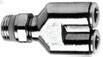

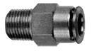

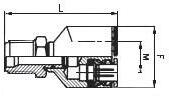
66 Male Tube Pipe Catalog O.D. Thread Number F M L 1/8 10-32* 1108x2A 0.83 0.39 1.04 1/8 1/8 1108x2 0.83 0.39 1.54 5/32 1/8 1108x2.5 0.83 0.39 1.54 1/4 1/8 1108x4 0.96 0.49 1.67
*UNF Thread. Seals with nylon washer (included).
Male Tube Pipe Catalog SW SW1 O.D. Thread Number C F G H L (mm) (mm) 1/8 1/8 1168x2 0.19 0.34 0.55 0.31 0.75 12 2.5 1/8 1/4 1168x2x4 0.35 0.34 0.62 0.47 0.90 14 2.5 5/32 1/8 1168x2.5 0.19 0.34 0.55 0.31 0.74 12 2.5 5/32 1/4 1168x2.5x4 0.35 0.34 0.62 0.49 0.90 14 2.5 1/4 1/8 1168x4 0.28 0.46 0.55 0.31 0.92 12 4 1/4 1/4 1168x4x4 0.40 0.46 0.62 0.49 1.04 14 4 1/4 3/8 1168x4x6 0.42 0.46 0.86 0.49 1.10 19 4 5/16 1/8 1168x5 0.39 0.53 0.62 0.31 1.08 14 5 5/16 1/4 1168x5x4 0.41 0.53 0.62 0.49 1.10 14 6 5/16 3/8 1168x5x6 0.41 0.53 0.86 0.49 1.10 19 6 3/8 1/8 1168x6x2 0.39 0.60 0.79 0.31 1.18 17 4 3/8 1/4 1168x6 0.55 0.60 0.79 0.47 1.34 17 7 3/8 3/8 1168x6x6 0.35 0.60 0.86 0.47 1.14 19 7 3/8 1/2 1168x6x8 0.39 0.60 1.00 0.61 1.16 22 7 1/2 3/8 1168x8 0.48 0.72 0.36 0.49 1.31 19 10 1/2 1/2 1168x8x8 0.42 0.72 1.00 0.61 1.26 22 10
Swivel Male “Y”
Male
Catalog Tube Fem. Number SW O.D. Pipe Thread C F G H L (mm) 1/8 1/8 1166x2 0.39 0.35 0.51 0.34 0.95 12 1/8 1/4 1166x2x4 0.55 0.35 0.65 0.47 1.10 15 5/32 1/8 1166x2.5 0.39 0.35 0.51 0.34 0.95 12 5/32 1/4 1166x2.5x4 0.55 0.35 0.65 0.47 1.10 15 1/4 1/8 1166x4 0.39 0.46 0.51 0.34 1.02 12 1/4 1/4 1166x4x4 0.54 0.47 0.65 0.47 1.18 15 3/8 1/4 1166x6 0.51 0.60 0.73 0.47 1.30 17 3/8 3/8 1166x6x6 0.55 0.60 0.79 0.49 1.34 17
*UNF Thread. Seals with nylon washer (included).
Connector
Female Connector
Swivel for installation purposes only.
L GF H C SW SW1 L G F SW H C Tube Catalog SW O.D. Number C F M (mm) 1/8 1165x2 0.14 0.35 0.69 8 5/32 1165x2.5 0.14 0.35 0.69 8 1/4 1165x4 0.16 0.50 0.79 9 5/16 1165x5 0.20 0.55 0.89 11 3/8 1165x6 0.26 0.65 1.04 13 1/2 1165x8 0.32 0.77 1.12 15 Union
C SW M F L FM
Allen wrench use permits close quarter installation not possible with a standard wrench.
Elbow
Push>Connect Page 65
Brass Products Push>Connect
Swivel Male Elbow
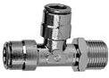
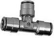


67 Male Tube Pipe Catalog SW SW1 O.D. Thread Number C E F H M (mm) (mm) 1/8 1/8 1169x2S 0.14 0.65 0.35 0.32 0.69 .32 .47 1/8 1/4 1169x2x4S 0.14 0.69 0.35 0.47 0.70 .32 .55 5/32 1/8 1169x2.5S 0.14 0.65 0.35 0.32 0.69 .32 .47 1/4 1/8 1169x4S 0.16 0.67 0.50 0.32 0.79 .35 .47 1/4 1/4 1169x4x4S 0.16 0.71 0.50 0.47 0.79 .35 .55 1/4 3/8 1169x4x6S 0.16 0.67 0.50 0.47 0.79 .35 .75 5/16 1/8 1169x5S 0.20 0.71 0.55 0.32 0.87 .43 .47 5/16 1/4 1169x5x4S 0.20 0.75 0.55 0.47 0.87 .43 .55 5/16 3/8 1169x5x6S 0.20 0.73 0.55 0.47 0.87 .43 .75 3/8 1/8 1169x6x2S 0.26 0.81 0.65 0.32 1.04 .51 .55 3/8 1/4 1169x6S 0.25 0.85 0.65 0.47 1.04 .51 .55 3/8 3/8 1169x6x6S 0.26 0.83 0.65 0.47 1.04 .51 .75 3/8 1/2 1169x6x8S 0.26 0.91 0.65 0.61 1.04 .51 .87 1/2 1/4 1169x8x4S 0.32 0.91 0.77 0.47 1.12 .59 .67 1/2 3/8 1169x8S 0.32 0.87 0.77 0.47 1.12 .59 .75 1/2 1/2 1169x8x8S 0.32 0.95 0.77 0.61 1.12 .59 .87
*UNF Thread. Seals with nylon washer (included).
Tube Male Catalog O.D Pipe Number SW Thread C E F H M (mm) 1/4 1/8 1169x4 0.16 0.57 0.50 0.47 0.79 9 1/4 1/4 1169x4x4 0.16 0.47 0.50 0.47 0.79 9 3/8 1/4 1169x6 0.26 0.55 0.65 0.47 1.04 13 3/8 3/8 1169x6x6 0.26 0.51 0.65 0.47 1.04 13 Male Elbow Tube Catalog SW O.D. Number C F L M (mm) 1/8 1164x2 0.14 0.35 1.38 0.69 8 5/32 1164x2.5 0.14 0.35 1.38 0.69 8 1/4 1164x4 0.16 0.50 1.57 0.79 9 5/16 1164x5 0.20 0.55 1.77 0.89 11 3/8 1164x6 0.26 0.65 2.09 1.04 13 1/2 1164x8 0.32 0.77 2.24 1.12 15 Union Tee Tube Male O.D. Pipe Catalog SW SW1 Thread Number E F H L M (mm) (mm) 1/8 10-32* 1171x2AS 0.53 0.39 0.18 1.53 0.89 9 8 1/8 1/8 1171x2S 0.65 0.35 0.32 1.54 0.69 8 12 5/32 10-32* 1171x2.5AS 0.53 0.39 0.18 1.50 0.79 9 8 5/32 1/8 1171x2.5S 0.65 0.35 0.32 1.54 0.69 8 12 5/32 1/4 1171x2.5x4S 0.69 0.35 0.26 1.63 0.69 8 14 1/4 1/8 1171x4S 0.67 0.46 0.49 1.65 0.79 9 12 1/4 1/4 1171x4x4S 0.71 0.50 0.32 1.75 0.79 9 14 1/4 3/8 1171x4x6S 0.69 0.50 0.47 1.77 0.79 9 19 3/8 1/4 1171x6S 0.85 0.65 0.47 2.15 1.04 13 14 3/8 3/8 1171x6x6S 0.83 0.65 0.47 2.17 1.04 13 19 3/8 1/2 1171x6x8S 0.91 0.65 0.61 2.28 1.04 13 22 1/2 1/4 1171x8x4S 0.91 0.79 0.47 2.29 1.12 15 13 1/2 3/8 1171x8S 0.87 0.79 0.47 2.29 1.12 15 19 1/2 1/2 1171x8x8S 0.95 0.79 0.61 2.40 1.12 15 22 *UNF Thread. Seals with nylon washer (included). Male Run Tee Swivel Swivel for installation purposes only. Swivel for installation purposes only. C SW M E H F SW1 C SW M E H F SW F F C L M SW F L E H M SW1
Page 66
Brass Products Push>Connect
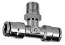
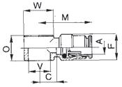
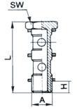
*UNF Thread. Seals with nylon washer (included).


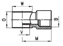
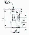
68 Male Tube Pipe Catalog O.D. Thread Number C E F H l SW SW1 1/8 10-32* 1172x2AS 0.24 0.53 0.39 0.18 1.61 0.35 0.32 1/8 1/8 1172x2S 0.14 0.65 0.35 0.32 1.38 0.32 0.47 5/32 10-32* 1172x2.5AS 0.24 0.56 0.39 0.18 1.57 0.35 0.32 5/32 1/8 1172x2.5S 0.14 0.65 0.35 0.32 1.38 0.32 0.47 5/32 1/4 1172x2.5x4S 0.14 0.67 0.35 0.47 1.38 0.32 0.55 1/4 1/8 1172x4S 0.16 0.67 0.50 0.32 1.57 0.35 0.47 1/4 1/4 1172x4x4S 0.16 0.71 0.50 0.47 1.57 0.35 0.55 1/4 3/8 1172x4x6S 0.16 0.69 0.50 0.47 1.57 0.35 0.75 3/8 1/4 1172x6S 0.26 0.85 0.65 0.47 2.09 0.51 0.55 3/8 3/8 1172x6x6S 0.26 0.83 0.65 0.47 2.09 0.51 0.75 3/8 1/2 1172x6x8S 0.26 0.91 0.65 0.61 2.09 0.51 0.87 1/2 1/4 1172x8x4S 0.32 0.91 0.77 0.47 2.24 0.59 0.67 1/2 3/8 1172x8S 0.32 0.89 0.77 0.47 2.24 0.59 0.75 1/2 1/2 1172x8x8S 0.32 0.95 0.77 0.61 2.24 0.59 0.87 *UNF Thread. Seals with nylon washer (included). Male Branch Tee Swivel Swivel for installation purposes only. Male Pipe Catalog Thread A Number H L S SW 10-32* 1184x1xA 0.16 0.71 0.18 0.32 1/8 1184x1x2 0.24 1.06 0.34 0.55 3/8 1184x1x6 0.35 1.18 0.34 0.75
Stud Manifolds Male Pipe Catalog Thread A Number H L SW 1/4 1185x2x4 0.32 1.79 0.67 Stud Manifolds Tube Catalog O.D. A Number C F M O V W 5/32 1181x2.5A 0.20 0.35 0.75 0.35 0.20 0.35 1/8 1181x2x2 0.32 0.39 0.89 0.57 0.39 0.55 1/4 1181x4x2 0.35 0.50 0.98 0.57 0.39 0.55 1/4 1181x4x4 0.43 0.50 1.06 0.57 0.52 0.71 Banjo Female Pipe Catalog Thread B Number V O M W 10-32* 1183xAxA 10-32 0.35 0.41 0.35 1/8 1183x2x2 1/8 0.57 0.79 0.55 1/4 1183x4x4 1/4 0.57 1.00 0.71 3/8 1183x6x6 3/8 0.57 1.10 0.83
Female Banjo SW F C L E SW1 H SW A H L S SW L H A W O M V C F A W O M V B
*UNF Thread. Seals with nylon washer (included).
Page 67
Brass Products
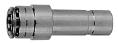
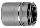
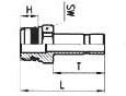
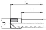
69 Tube Catalog O.D. (mm) Number F G L S H B 5 1161x5M 9.60 10.0 15.5 9.750 11.5 3.5 6 1161x6M 11.8 12.2 16.5 11.95 12.0 4.0 8 1161x8M 13.8 14.2 18.0 13.95 14.0 6.0 Tube O.D. (mm) Catalog Number L P T 4 1129x4MRP 29.0 8 20.0 5 1129x5MRP 29.5 8 20.5 6 1129x6MRP 31.5 8 22.5 8 1129x8MRP 34.5 12 24.5 10 1129x10MRP 37.0 12 27.0 12 1129x12MRP 40.5 16 28.5 Cartridge Plug (plastic) Tube O.D. (mm) Catalog Number L 4 1105x4M 32.5 6 1105x6M 35.5 8 1105x8M 40.5 10 1105x10M 46.0 Double Union Tube O.D. Tube O.D. Catalog A (mm) B (mm) Number C F L T 4 6 1109x4Mx6M 15.5 9 29.5 18.0 6 8 1109x6Mx8M 18.0 13 34.0 20.5 6 10 1109x6Mx10M 20.5 13 36.5 23.0 8 10 1109x8Mx10M 20.5 14 39.0 23.0 8 12 1109x8Mx12M 21.5 14 39.0 24.0 Reducer Tube O.D. BSPP D Thd. Size Catalog (mm) (mm) Number H T L SW 4 1/8 1180x4Mx2PP 5.5 16.5 27.8 12 5 1/8 1180x5Mx2PP 5.5 18.0 29.3 12 6 1/8 1180x6Mx2PP 5.5 18.0 29.3 12 6 1/4 1180x6Mx4PP 7.0 18.0 31.0 14 8 1/8 1180x8Mx2PP 5.5 20.5 31.8 12 8 1/4 1180x8Mx4PP 7.0 20.5 33.5 14 10 1/4 1180x10Mx4PP 7.0 23.0 36.0 14 10 3/8 1180x10Mx6PP 8.0 23.0 37.3 19 12 3/8 1180x12Mx6PP 8.0 24.0 38.3 19 Tube O.D. (mm) Catalog Number F G L N 4 1162x4M 8.40 9 29.0 14.0 5 1162x5M 9.80 11 32.0 15.0 6 1162x6M 11.7 12 34.0 15.5 8 1162x8M 13.7 14 37.0 17.5 10 1162x10M 15.4 17 41.5 20.0 12 1162x12M 18.3 19 43.5 21.0 Stem Adapter Union Joins Metric Push>Connect fittings. Joins metric tubing. H B S F T L C L G F N L T P A B F G L SW L T H L
Metric Page 68
Push>Connect
Brass Products
Push>Connect Metric
Allen wrench use permits close quarter installation not possible with a standard wrench.
Allen wrench use permits close quarter installation not possible with a standard wrench.
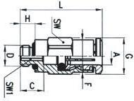
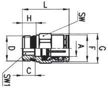
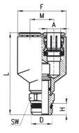
Female Connector (BSPP)
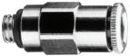

*M5x0.8 is M profile thread. Seals with nylon washer (included).

70 Tube Catalog O.D. (mm) Number F C L M 4 1107x4M 18.0 5.0 33.0 9.0 6 1107x6M 24.5 7.0 39.0 12.5 8 1107x8M 28.5 9.0 44.0 14.5 10 1107x10M 32.0 15.5 53.5 16.0 Union “Y” Tube Thread O.D. Size Catalog SW (mm) A BSP D Number F H M L (mm) 4 1/8 1108x4Mx2PT 18.0 5.5 9 38.0 12 6 1/8 1108x6Mx2PT 24.5 5.5 12.5 41.5 12 *M5x0.8 metric screw thread. Seals with nylon washer (included). Male “Y” Tube Thread O.D Size Catalog SW SW1 (mm) A BSP D Number C F G H L (mm) (mm) 4 1/8 1168x4Mx2PT 3.8 8.80 13.2 5.5 18.0 12 2.5 4 1/4 1168x4Mx4PT 6.0 8.80 15.2 7.0 19.5 14 2.5 5 1/8 1168x5Mx2PT 3.8 9.80 13.2 5.5 19.0 12 3.0 5 1/4 1168x5Mx4PT 5.5 9.80 15.2 7.0 20.0 14 3.0 6 1/8 1168x6Mx2PT 5.0 11.7 13.2 5.5 20.5 12 4.0 6 1/4 1168x6Mx4PT 5.5 11.7 15.2 7.0 21.0 14 4.0 8 1/8 1168x8Mx2PT 7.5 13.7 15.2 5.5 25.0 14 5.0 8 1/4 1168x8Mx4PT 6.5 13.7 15.2 7.0 24.0 14 6.0 8 3/8 1168x8Mx6PT 6.5 13.7 20.5 8.0 23.5 19 6.0 10 1/4 1168x10Mx4PT 8.5 16.3 18.5 7.0 28.5 17 7.0 10 3/8 1168x10Mx6PT 5.5 16.3 20.5 8.0 25.5 19 8.0 10 1/2 1168x10Mx8PT 5.0 16.3 24.5 9.0 25.0 22 8.0 12 1/4 1168x12Mx4PT 10.5 18.3 20.5 7.0 31.5 19 7.0 12 3/8 1168x12Mx6PT 9.5 18.3 20.5 8.0 30.5 19 9.0 12 1/2 1168x12Mx8PT 6.0 18.3 24.5 9.0 27.0 22 10.0 Male Connector (Universal BSPT/BSPP) Tube O.D. Thread Catalog SW SW1 (mm) A Size Number C F G H L (mm) (mm) 5 M5* 1168x5Mx5MM 5.5 8.8 9.9 3.5 20.5 9 2 6 M5* 1168x6Mx5MM 5.5 11.7 13.2 3.5 21.5 12 2 *M5x0.8 metric screw thread. Seals with nylon washer (included). Male Connector Tube Thread O.D. Size Catalog SW (mm) A BSPP Number C F G H L (mm) 4 1/8 1166x4Mx2PP 10.0 9.0 13.0 7.5 24.0 12 4 M5* 1166x4Mx5MM 6.5 7.8 8.8 5.0 20.5 8 6 1/8 1166x6Mx2PP 10.0 11.7 13.0 7.5 26.0 12 6 1/4 1166x6Mx4PP 11.5 11.9 16.5 11.0 27.5 15 8 1/8 1166x8Mx2PP 9.5 13.7 15.2 7.5 27.0 14 8 1/4 1166x8Mx4PP 11.5 13.7 16.5 11.0 29.0 15 10 1/4 1166x10Mx4PP 11.5 15.7 18.5 11.0 31.5 17
C M L F H GF C L SW
H M A D F L SW A D H GF C L SW SW1 G C D F A H L SW SW1 Tube Catalog SW SW1 T O.D. (mm)Number B F L N MAX (mm) (mm) 4 1174x4M M10x1 8.40 29.0 14.5 10.5 14 14 20.0 5 1174x5M M12x1 9.80 31.0 15.0 10.5 17 17 20.0 6 1174x6M M14x1 11.7 33.0 16.0 10.5 17 17 20.0 8 1174x8M M16x1 13.7 36.0 17.5 11.5 19 19 21.0 10 1174x10M M18x1 15.4 41.5 20.0 13.0 22 22 23.5 12 1174x12M M20x1 18.3 43.5 21.0 14.5 24 24 25.0 Bulkhead Union N MAX B F T L SW SW1
Page 69
Brass Products Push>Connect Metric

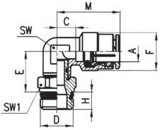
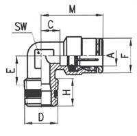

Swivel for installation purposes only.


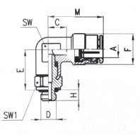
71
Union Elbow
Male Elbow (Universal BSPT/BSPP)
Male Elbow Swivel (Universal BSPT/BSPP)
Tube Catalog SW O.D. (mm) Number C F M (mm) 4 1165x4M 3.5 9.0 17.5 8 5 1165x5M 6.0 11.0 21.0 9 6 1165x6M 4.0 12.7 20.0 9 8 1165x8M 5.0 14.0 22.5 11 10 1165x10M 6.5 16.5 26.5 13 12 1165x12M 7.5 19.5 28.5 15 Tube Thread O.D. A Size Catalog SW (mm) BSP D Number C E F H M (mm) 4 1/8 1169x4Mx2PT 3.5 8.5 9.0 7.5 17.5 8 4 1/4 1169x4Mx4PT 6.0 11.5 10.0 12 20.0 9 5 1/8 1169x5Mx2PT 6.0 9.5 11.0 7.5 21.0 9 5 1/4 1169x5Mx4PT 6.0 10.5 11.0 11.0 21.0 9 6 1/8 1169x6Mx2PT 4.0 9.0 12.7 7.5 20.0 9 6 1/4 1169x6Mx4PT 4.0 11.5 12.7 12 20.0 9 8 1/8 1169x8Mx2PT 5.0 10.5 14.0 7.5 22.5 11 8 1/4 1169x8Mx4PT 5.0 11.5 14.0 12.5 22.5 11 8 3/8 1169x8Mx6PT 7.5 13.0 15.0 11.5 25.0 12 10 1/4 1169x10Mx4PT 6.5 13.0 16.5 12 26.5 13 10 3/8 1169x10Mx6PT 6.5 12.5 16.5 11.5 26.5 13 12 1/4 1169x12Mx4PT 7.5 14.5 19.5 12 28.5 15 12 3/8 1169x12Mx6PT 7.5 14.5 19.5 12.5 28.5 15 Tube Thread O.D. A Size Catalog SW SW1 (mm) BSP D Number C E F H M (mm) (mm) 4 1/8 1169x4Mx2PTS 3.5 14.5 9.0 5.5 17.5 8 12 4 1/4 1169x4Mx4PTS 3.5 14.5 9.0 7.0 17.5 8 14 5 1/8 1169x5Mx2PTS 6.0 14.5 11.0 5.5 21.0 9 12 5 1/4 1169x5Mx4PTS 6.0 14.5 11.0 7.0 21.0 9 14 6 1/8 1169x6Mx2PTS 4.0 15.0 12.7 5.5 20.0 9 12 6 1/4 1169x6Mx4PTS 4.0 15.0 12.7 7.0 20.0 9 14 8 1/8 1169x8Mx2PTS 5.0 16.0 14.0 5.5 22.5 11 12 8 1/4 1169x8Mx4PTS 5.0 16.0 14.0 7.0 22.5 11 14 8 3/8 1169x8Mx6PTS 5.0 16.5 14.0 8.0 22.5 11 19 10 1/4 1169x10Mx4PTS 6.5 18.5 16.5 7.0 26.5 13 14 10 3/8 1169x10Mx6PTS 6.5 19.0 16.5 8.0 26.5 13 19 10 1/2 1169x10Mx8PTS 6.5 19.5 16.5 9.0 26.5 13 22 12 1/4 1169x12Mx4PTS 7.5 20.0 19.5 7.0 28.5 15 17 12 3/8 1169x12Mx6PTS 7.5 20.0 19.5 8.0 28.5 15 19 12 1/2 1169x12Mx8PTS 7.5 20.5 19.5 9.0 28.5 15 22 C M F SW M C D F A E H SW Tube O.D. A Thread Catalog SW SW1 (mm) Size Number C E F H M (mm) (mm) 4 M5* 1169x4Mx5MMS 6 12.5 11.0 4 21 9 8 5 M5* 1169x5Mx5MMS 4 13.0 12.7 4 20 9 10 *M5x0.8 metric screw thread. Seals with nylon washer (included). M C D FA E H SW SW1 Male Elbow Swivel Swivel for installation purposes only. M C D F A E H SW SW1
Page 70
Brass Products
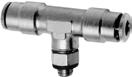
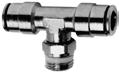
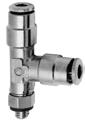
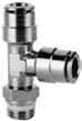
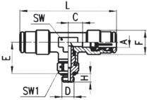
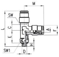
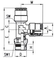
Push>Connect Metric
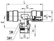
72 Union Tee Tube Catalog SW O.D. (mm) Number C F L M (mm) 4 1164x4M 3.5 9.0 35 17.5 8 5 1164x5M 6.0 11.0 42 21.0 9 6 1164x6M 4.0 12.7 40 20.0 9 8 1164x8M 5.0 14.0 45 22.5 11 10 1164x10M 6.5 16.5 53 26.5 13 12 1164x12M 7.5 19.5 57 28.5 15 M C F F L F SW Male Run Tee Swivel (Universal BSPT/BSPP) Tube Thd. O.D. A Size Catalog SW SW1 (mm) BSP D Number C E F H l m (mm)(mm) 4 1/8 1171x4Mx2PTS 3.5 14.5 9.0 5.5 37.5 17.5 8 12 5 1/8 1171x5Mx2PTS 6.0 14.5 11.0 5.5 41.0 21.0 9 12 5 1/14 1171x5Mx4PTS 6.0 14.5 11.0 7.0 42.5 21.0 9 14 6 1/8 1171x6Mx2PTS 4.0 15.0 12.7 5.5 40.0 20.0 9 12 6 1/4 1171x6Mx4PTS 4.0 15.0 12.7 7.0 41.5 20.0 9 14 8 3/8 1171x8Mx6PTS 5.0 16.5 14.0 8.0 47.0 22.5 13 19 10 1/4 1171x10Mx4PTS 6.5 18.5 16.5 7.0 52.0 26.5 13 14 10 3/8 1171x10Mx6PTS 6.5 18.5 16.5 8.0 53.5 26.5 15 19 12 3/8 1171x12Mx6PTS 7.5 19.5 19.5 8.0 56.5 28.5 16 19 M C H F A D L E SW SW1 Male Run Tee Swivel Tube O.D. A Thd. Catalog SW SW1 (mm) Size Number C E F H l M (mm)(mm) 4 M5* 1171x4Mx5MMS 3.5 12.5 9 4 34 17.5 8 8 5 M5* 1171x5Mx5MMS 6.0 12.5 11 4 37 21.0 9 8 *M5x0.8 metric screw thread. Seals with nylon washer (included). M C H F A D L E SW SW1 Male Branch Tee Swivel (Universal BSPT/BSPP) Tube Thread O.D. A Size Catalog SW SW1 (mm) BSP D Number C E F H l (mm) (mm) 4 1/8 1172x4Mx2PTS 3.5 14.5 9.0 5.5 35 8 12 5 1/8 1172x5Mx2PTS 6.0 14.5 11.0 5.5 42 9 12 5 1/4 1172x5Mx4PTS 6.0 14.5 11.0 7.0 42 9 14 6 1/8 1172x6Mx2PTS 4.0 15.0 12.7 5.5 40 9 12 6 1/4 1172x6Mx4PTS 4.0 15.0 12.7 7.0 40 9 14 8 1/8 1172x8Mx2PTS 5.0 16.0 14.0 5.5 45 11 12 8 1/4 1172x8Mx4PTS 5.0 16.0 14.0 7.0 45 11 14 8 3/8 1172x8Mx6PTS 5.0 16.5 14.0 8.0 45 11 19 10 1/4 1172x10Mx4PTS 6.5 18.5 16.5 7.0 53 13 14 10 3/8 1172x10Mx6PTS 6.5 19.0 16.5 8.0 53 13 19 12 1/4 1172x12Mx4PTS 7.5 20.0 19.5 7.0 57 15 17 12 3/8 1172x12Mx6PTS 7.5 20.0 19.5 8.0 57 15 19 12 1/2 1172x12Mx8PTS 7.5 20.5 19.5 9.0 57 15 22 C H F A D L E SW SW1 Tube O.D. A Thread Catalog SW SW1 (mm) Size Number C E F H l (mm) (mm) 4 M5* 1172x4Mx5MMS 3.5 14.5 9 4 35 8 8 *M5x0.8 metric screw thread. Seals with nylon washer (included). C H F A D L E SW SW1 Male Branch Tee Swivel Swivel for installation purposes only. Swivel for installation purposes only. Swivel for installation purposes only. Swivel for installation purposes only.
Page 71
Brass Products
Push>Connect Flow Controls
Technical Data
Valve: Flow Regulator
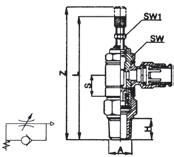
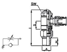
Regulation: Adjustable Screw
Material: Brass; Nickel Plated
Seals: Buna-N
Note: For additional technical questions, contact Technical Support at 1-888-258-0222.
Threads: 10-32 UNF - 1/8 - 1/4 - 3/8
NPTF
Tube Sizes: 1/8 - 5/32 - 1/4 - 3/8
Operating Pressures: to 150 PSI
Nominal Diameter: 10-32 UNF = .059 - 1/8 = .078 1/4 = .157 - 3/8 = .275
Note: We reserve the right to alter these specifications without prior notice.
Air flow (SCFM) from B to A
With adjustment open 1.9
With adjustment closed 1.4
Air flow (SCFM) from B to A
With adjustment open 15
With adjustment closed 8
73
SW
S L SW1
Z L S
A H
SW H A
Right Angle Flow Control and Needle Valves SCU-MCU 0 0.00 0.40 0.60 0.80 1.00 1.20 1.40 1.60 0.20 42 6810 10-32” Number of Turns Flow (SCFM of Air) 1/8” 042681012 14 16 Number of Turns 0.00 1.00 2.00 3.00 4.00 5.00 6.00 Flow (SCFM of Air) 0 0.00 2.00 4.00 6.00 8.00 10.00 12.00 42 681012 14 1/4” Number of Turns Flow (SCFM of Air) 3/8” 042681012 14 16 18 20 22 Number of Turns 0.00 5.00 10.00 15.00 20.00 25.00 Flow (SCFM of Air)
With
closed 13 Flow Control Valve Performance Air flow is determined with 85 PSI at the in port and with 70 PSI at the outlet
Air flow (SCFM) from B to A With adjustment open 23
adjustment
Page 72
Brass Products
M C U – 04 02 3 5 6 4 SCU MCU
2 1
Thread B
SCU SCU MCU
Port A
SW B
S L SW B
H
, 2 Port A
Coding of Banjo flow controllers 4 Function U= unidirectional (flow control 5 Port A 6 Thread B Catalog Tube B SW Number O.D NPTF S H L (mm) A555SCUx2.5A* 5/32 10-32 0.22 0.18 1.141 8 A55SCUx2.5x2 5/32 1/8 0.51 0.37 2.000 14 A55SCUx4x2 1/4 1/8 0.51 0.37 2.000 14 A55SCUx4x4 1/4 1/4 0.45 0.51 2.250 17 A55SCUx6x4 3/8 1/4 0.45 0.51 2.250 17 A55SCUx6x6 3/8 3/8 0.48 0.51 2.440 19 *UNF Thread Thread B
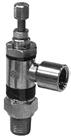
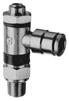
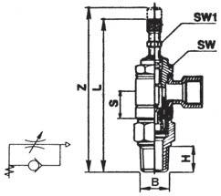
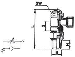
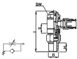
Port A
S L Z
H
SL SW SW1 B
H
Banjo Catalog Female B SW Number Thread NPTF S H L (mm) A557SCUx2x2 1/8 1/8 0.51 0.37 2.00 14 A557SCUx4x4 1/4 1/4 0.45 0.51 2.25 17 A557SCUx6x6 3/8 3/8 0.48 0.51 2.44 19 *UNF Thread Banjo Catalog Female B SW SW1 Number Thread NPTF S H L Z (mm) (mm) A557MCUx2x2 1/8 1/8 0.51 0.37 2.38 2.56 14 7 A557MCUx6x6 3/8 3/8 0.48 0.51 2.95 3.25 19 10 Thread B
Page 73
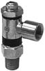
74
1
Identification of flow control These unidirectional flow controllers have been designed as small as possible so as to be mounted directly on valves or cylinders. , Adjustment M=Manual S=Screwdriver 3 , Assembly C=On cylinders
Push>Connect Flow Controls
Brass Products Push>Connect Plus
Eaton is proud to announce three design changes to Push>Connect products. The introduction of a low profile, sure-seal design for male NPTF threaded fittings is here. Also, an improved collet design will allow use with all types of tubing from Nylon to 90A durometer Polyurethane, including Polyethylene, and PVC tubing. Lastly, the male swivel design provides greater strength and stability.
Below is a summary of features and benefits for the newly named Push>Connect Plus.
Perfect thread seal: A captured Teflon® ring around the base of the hex
shoulder, seals similar to a reusable (SAE type) seal eliminates thread sealant and loose particles associated with thread sealant.
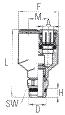
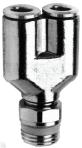
Lower Profile: Push>Connect Plus has a lower profile for those tight places. A shorter thread design eliminates exposed threads where dirt and bacteria can collect (ideal for food processing and hygienic applications).

More Versatility: The new brass collet is designed for use with all types of tubing from Nylon to 90A durometer Polyurethane, including Polyethylene, and PVC tubing.
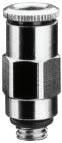
Note:
For additional technical questions, contact Technical Support at 1-888-258-0222.
Super-quick Installations: New short thread length means fewer turns and super-quick installations.
Improved Swivel Design: Strength and stability have been engineered into the new male swivel.
Universal Thread: Use with NPT, BSPP, and BSPT ports.
The new part will have a ‘P’ in the part number to signify the new design. An example of this change is previous #1169x4S becomes #1169Px4S. Current Push>Connect parts with 10-32UNF threads and ending in ‘A’ (eg.1168x2A) will continue with the current thread design.
75
Swivel Male “Y” Male Connector Catalog Tube Male Number O.D. Pipe Thread F H M L 1/8 1/8 1108Px2S 0.83 0.20 0.39 1.28 5/32 1/8 1108Px2.5S 0.83 0.20 0.39 1.28 1/4 1/8 1108Px4S 0.96 0.20 0.49 1.40 Tube Male Pipe Catalog SW SW1 O.D. A Thread D Number F G H L (mm) (mm) 1/8 10-32* 1168Px2A 0.346 0.411 0.177 0.846 9 2.0 1/8 1/8 1168Px2 0.346 0.551 0.200 0.728 12 2.5 1/8 1/4 1168Px2x4 0.346 0.629 0.255 0.807 14 2.5 5/32 10-32* 1168x2.5A 0.346 0.411 0.177 0.807 9 2.0 5/32 1/8 1168Px2.5 0.346 0.551 0.200 0.728 12 2.5 5/32 1/4 1168Px2.5x4 0.346 0.629 0.255 0.807 14 2.5 1/4 10-32* 1168x4A 0.460 0.551 0.177 0.905 12 2.0 1/4 1/8 1168Px4 0.460 0.551 0.200 0.807 12 4.0 1/4 1/4 1168Px4x4 0.460 0.629 0.255 0.846 14 4.0 1/4 3/8 1168Px4x6 0.460 0.866 0.294 0.885 19 4.0 5/16 1/8 1168Px5 0.539 0.629 0.200 0.945 14 5.0 5/16 1/4 1168Px5x4 0.539 0.629 0.255 0.945 14 6.0 5/16 3/8 1168Px5x6 0.539 0.866 0.294 0.924 19 6.0 3/8 1/8 1168Px6x2 0.610 0.776 0.200 1.082 17 5.0 3/8 1/4 1168Px6 0.610 0.776 0.255 1.102 17 7.0 3/8 3/8 1168Px6x6 0.610 0.866 0.294 0.945 19 7.0 3/8 1/2 1168Px6x8 0.610 1.004 0.335 0.984 22 7.0 1/2 3/8 1168Px8 0.720 0.866 0.294 1.161 19 10.0 1/2 1/4 1168Px8x4 0.720 0.866 0.255 1.161 19 7.0 1/2 1/2 1168Px8x8 0.720 1.004 0.335 1.062 22 10.0
*UNF Thread
*Teflon® is a registered trademark of DuPoint used license by Eaton. Page 74
Brass Products
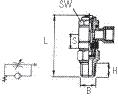
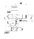
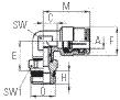
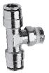
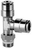
Push>Connect Plus
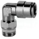
76
Male Tube Pipe Catalog SW SW1 O.D. Thd. Number C E F H M (mm) (mm) 1/8 1/8 1169Px2S 0.14 0.59 0.35 0.20 0.69 8 12 1/8 1/4 1169Px2x4S 0.14 0.63 0.35 0.26 0.69 8 14 5/32 1/8 1169Px2.5S 0.14 0.59 0.35 0.20 0.69 8 12 5/32 1/4 1169Px2.5x4S 0.14 0.63 0.35 0.26 0.69 8 14 1/4 1/8 1169Px4S 0.16 0.63 0.46 0.20 0.79 9 12 1/4 1/4 1169Px4x4S 0.16 0.65 0.46 0.26 0.79 9 14 1/4 3/8 1169Px4x6S 0.16 0.65 0.46 0.29 0.79 9 19 5/16 1/8 1169Px5S 0.20 0.65 0.54 0.20 0.89 11 12 5/16 1/4 1169Px5x4S 0.20 0.69 0.54 0.26 0.89 11 14 5/16 3/8 1169Px5x6S 0.20 0.69 0.54 0.29 0.89 11 19 3/8 1/8 1169Px6x2S 0.26 0.75 0.64 0.20 1.04 13 14 3/8 1/4 1169Px6S 0.26 0.77 0.64 0.26 1.04 13 14 3/8 3/8 1169Px6x6S 0.26 0.77 0.64 0.29 1.04 13 19 3/8 1/2 1169Px6x8S 0.26 0.79 0.64 0.34 1.04 13 22 1/2 1/4 1169Px8x4S 0.32 0.81 0.72 0.26 1.12 15 17 1/2 3/8 1169Px8S 0.32 0.81 0.72 0.29 1.12 15 19 1/2 1/2 1169Px8x8S 0.32 0.83 0.72 0.36 1.12 15 22
Swivel Male Elbow
Male Tube Pipe Catalog SW SW1 O.D. Thd. Number C E F H l M (mm) (mm) 1/8 1/8 1171Px2S 0.14 0.59 0.35 0.20 1.46 0.69 8 12 5/32 1/8 1171Px2.5S 0.14 0.59 0.35 0.20 1.46 0.69 8 12 5/32 1/4 1171Px2.5x4S 0.14 0.63 0.35 0.26 1.57 0.69 8 14 1/4 1/8 1171Px4S 0.16 0.63 0.50 0.20 1.61 0.89 9 12 1/4 1/4 1171Px4x4S 0.16 0.65 0.50 0.26 1.70 0.79 9 14 1/4 3/8 1171Px4x6S 0.16 0.65 0.50 0.30 1.73 0.79 9 19 3/8 1/4 1171Px6S 0.26 0.77 0.65 0.26 2.07 1.04 13 14 3/8 3/8 1171Px6x6S 0.26 0.77 0.65 0.30 2.11 1.04 13 19 3/8 1/2 1171Px6x8S 0.26 0.79 0.65 0.33 2.16 1.04 13 22 1/2 1/4 1171Px8x4S 0.32 0.81 0.77 0.26 2.18 1.12 15 17 1/2 3/8 1171Px8S 0.32 0.81 0.77 0.30 2.22 1.12 15 19 1/2 1/2 1171Px8x8S 0.32 0.83 0.77 0.33 2.28 1.12 15 22 Male Run Tee Swivel male Tube pipe Catalog SW SW1 O.D. thd. Number C E F H L M (mm) (mm) 1/8 1/8 1172Px2S 0.14 0.59 0.35 0.20 1.38 8 12 5/32 1/8 1172Px2.5S 0.14 0.59 0.35 0.20 1.38 8 12 5/32 1/4 1172Px2.5x4S 0.14 0.63 0.35 0.26 1.38 8 14 1/4 1/8 1172Px4S 0.16 0.61 0.50 0.20 1.51 9 12 1/4 1/4 1172Px4x4S 0.16 0.65 0.50 0.26 1.51 9 14 1/4 3/8 1172Px4x6S 0.16 0.65 0.50 0.30 1.51 9 19 3/8 1/4 1172Px6S 0.26 0.77 0.65 0.26 2.09 13 14 3/8 3/8 1172Px6x6S 0.26 0.77 0.65 0.30 2.09 13 19 3/8 1/2 1172Px6x8S 0.26 0.79 0.65 0.32 2.09 13 22 1/2 3/8 1172Px8S 0.32 0.81 0.77 0.30 2.24 15 19 Swivel for installation purposes only. Swivel for installation purposes only. Male Branch Tee Swivel
Swivel for installation purposes only.
Page 75
Brass Products Mini-Barb
Typical Application: Temperature control circuits, test apparatus, lubricant, coolant lines, pneumatic circuits, vacuum and fluid systems.
Pressure: Will withstand burst pressures of plastic tubing.
Vibration: Excellent resistance.
Temperature Range: Depends on tubing used.
Material: CA360 Brass.
Note: For additional technical questions, contact Technical Support at 1-888-258-0222.
Refer to safety information regarding proper selection of tubing and tube connectors on page 5.
Used With: PT240 Polyethylene tubing. See pages 25-29 for material compatibility and pages 30-32 for plastic tubing.
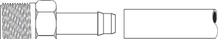

Advantages: Quick connecting - no tube preparation. Hand assembly. Low cost one-piece push-on design. Barbed lip provides safe, positive connection. Compact size permits use in extremely tight areas.
Conformance: An exclusive item with Eaton. User approvals only.
How to Order: Individually by catalog number.
Note: Refer to current price list for availability of cataloged items. Quotations and delivery of non-stock items supplied on request. Configurations and dimensions subject to change without notice.
Assembly Instructions:
1. Push the tubing over insert.
2. Bottom the tubing against connector body.
Label Set:
FS-1000 (adhesive)
CL-496 (non-adhesive)
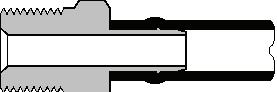
77 Tubing O.D. D E J 5/32 .062 .113 .380 *3/16 .078 .125 .500 1/4 .127 .189 .500 3/8 .196 .270 .500 1/2 .312 .395 .630 *No barb on 3/16” size.
Common Dimensions of Barbed End.
Page 76
Brass Products Mini-Barb


For replacement nuts and sleeves see page 47.


78 Plug Tubing Catalog Dia. O.D. Number C L 1/4 1073x4 0.31 0.75 3/8 1073x6 0.40 0.75 1/2 1073x8 0.53 0.88 MTO - Made To Order Solder Connector Tubing Solder Catalog Dia. O.D. Conn. Number C D1 J1 L 1/4 1/4 1079x4x4 5/16 0.25 0.50 1.00
Union Tubing Catalog Dia. O.D Number C L 1/4x3/16* 1062x4x3 1/4 1.25 1/4 1062x4 1/4 0.81 1/4 1062x4L 1/4 1.25 3/8x1/4 1062x6x4 5/16 1.19 3/8 1062x6 5/16 1.19 1/2x1/4 1062x8x4 1/2 1.33 1/2x3/8 1062x8x6 1/2 1.33 1/2 1062x8 1/2 1.45 *No barb on 3/16" end. “L” Suffix designates long Union. MTO - Made To Order Male Connector Tubing Male Pipe Catalog D1 O.D Thread Number D Opt. L 5/32 1/8 1068x2.5x2 7/16 0.06 0.19 0.98 1/4 1/16 1068x4x1 5/16 0.12 – 1.06 1/4 1/8 1068x4 7/16 0.12 0.19 1.06 1/4 1/4 1068x4x4 9/16 0.12 0.28 1.28 3/8 1/8 1068x6x2 7/16 0.19 – 1.09 3/8 1/4 1068x6 9/16 0.19 0.28 1.28 1/2 3/8 1068x8 11/16 0.31 – 1.38 Female Connector Tubing Fem. Pipe Catalog O.D Thread Number L 1/4 1/8* 1066x4 1/2 1.00 1/4 1/4 1066x4x4 11/16 1.25 3/8 1/4 1066x6 11/16 1.25
MTO
Compression Connector Tubing Comp. Catalog O.D Tube Size Number L 3/16* 1/4 1078x3x4 7/16 1/2 1.29 1/4 1/4 1078x4x4 7/16 1/2 1.29
*PTF Short Thread
- Made To Order
*No Barb on 3/16" end
Page 77
Brass Products Mini-Barb
For replacement compression nuts and sleeves, see page 47.


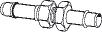

For replacement nuts and sleeves, see page 47 & 48.

79 Bulkhead Compression Connector Tubing Comp. Catalog Max. Thread O.D. Tube Size Number K L P T 1/4 1/4 1067x4x4 7/16 1/2 0.88 1.66 0.19 5/16-24 UNF Bulkhead Union Tubing Thread Catalog Max. O.D. T Number K L P 1/4 5/16–24 UNF 1074x4 7/16 1.06 1.74 0.31 3/8 3/8–24 UNF 1074x6 1/2 1.06 1.74 0.31 Union Elbow Tubing Catalog O.D Number M 1/4 1065x4 0.70 3/8 1065x6 0.67 1/2 1065x8 0.94 90° Male Elbow Tubing Male Pipe Catalog O.D. Thread Number D1 M N 1/4 1/16 1069x4x1 .156 .670 .550 1/4 1/8 1069x4 .250 .720 .630 1/4 1/4* 1069x4x4 .312 .780 .650 3/8 1/8 1069x6x2 .250 .740 .590 3/8 1/4* 1069x6 .312 .780 .620 1/2 3/8* 1069x8 .406 .980 .810 *PTF Short Thread 90° Female Elbow Tubing Fem. Pipe Catalog O.D Thread Number M N 1/4 1/8 1070x4 .750 .580 3/8 1/8 1070x6x2 .780 .480 3/8 1/4 1070x6 .840 .800
Page 78
Brass Products Mini-Barb


80 Tubing Catalog O.D. Number M N M1 1/4 1064x4 0.70 0.70 0.70 3/8x3/8x1/4 1064x6x6x4 0.70 0.74 0.70 3/8 1064x6 0.68 0.67 0.68 3/8x1/2x3/8 1064x6x8x6 0.76 0.75 0.86 1/2x1/2x1/4 1064x8x8x4 0.86 0.80 0.86 1/2x1/2x3/8 1064x8x8x6 0.86 0.76 0.86 1/2 1064x8 0.86 0.86 0.86 Union Tee Tubing Male Pipe Catalog O.D. Thread Number D1 L M N 1/4 1/8 1071x4 .188 1.21 0.71 0.59 *PTF Short Thread Male Run Tee Tubing Male Pipe Catalog O.D Thread Number D1 M N 1/4 1/8 1072x4 .188 .720 .590 3/8 1/8 1072x6x2 .188 .720 .590 3/8 1/4 1072x6 .312 .780 .620 Male Branch Tee Tubing Female Pipe Catalog O.D. Thread Number M N 1/4 1/8 1077x4 0.77 0.48 Female Branch Tee Tubing M&F Catalog O.D Pipe Thread Number L M N 1/4 1/8* 1075x4 2.00 0.75 0.39 *PTF Special Short Thread Adapter Tee
Page 79
Brass Products
Quick>Connect Air Brake - Brass & Composite
Note: For additional technical questions, contact Technical Support at 1-888-258-0222.
Refer to safety information regarding proper selection of tubing and tube connectors on page 5.
Typical Application: Air brake systems except where temperatures exceed +200°F or where battery acid can drip on tubing. Not for fuel, water or oil.
Pressure: Vacuum to 150 psi.
Vibration Moderate vibration resistance.
Material: CA360 Brass (Body & Collet). EP (Ethylene Propylene)o-ring.
Used With: SAE J844 Type A and B. Temperature Range: -40°F to +200°F (-40°C to +93°C)
Advantages: Easy, fast assembly, onepiece fitting, reusable Field Serviceable (See collet repair kits, page 89).
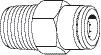
Used With: Eaton Air Brake Tubing.
Conformance: Meets D.O.T. FMVSS 571.106 and SAE J1131 air brake system performance requirements.
How to Order: Order individually by catalog number (parts are standard with thread sealant).
Label Set: FS-3300 (adhesive) CL-503 (non-adhesive)
Note: Refer to current price list for availability of cataloged items. Quotations and delivery of non-stock items supplied on request. Configurations and dimensions subject to change without notice. Additional information can be found in SAE J2494.
Assembly Instructions: See following page.
Cartridge Information
Encapsulated:
For insertion into single bore cavity in substitution for pipe thread ports. Meets proposed SAE specifications for encapsulated press in style Air Brake connectors.
Note:
Encapsulated Cartridges are specifically designed for installation into a thermoplastic (Nylon/Glass filled Nylon/Acetal) or a soft metal (Aluminum/Brass) cavity. For cavity dimensions contact Eaton Technical Support at 1-888-258-0222.
Four-Step Cartridge: When you clean sheet a component design, the FourStep Cartridge is an economical substitute for the encapsulated design. Special order only.
Select the design that is right for you. For applications where manifolds (manufactured from aluminum, plastic and brass) and air tanks (manufactured from steel and plastic composites) are used, contact Eaton Technical Support at 1-888258-0222 for quotes based on your specific requirements and volumes.
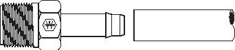
81
Page 80
Brass Products
Quick>Connect Air Brake - Brass & Composite
Disassembly
1. Using a tube cutter, make a square cut edge (maximum 15° cutting angle allowed).
2. Insert tubing straight into connector until a solid stop is felt. The tubing grip and seal (on o-ring) is now accomplished.
3. Gently tug on tubing to ensure tubing is secure.
1. Check to be sure there isn’t any air pressure.
2. Depress collet head using fingers or tube-release tool to release grip on tubing.
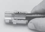
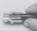

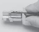
3. With the collet depressed, pull the tubing from the connector.
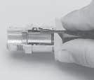
82
Assembly
90° 15° max. Tube Installation Gentle Tug Tube Release Tool Keep Collet Depressed Remove Tube Keep Collet Depressed Remove Tube
Page 81
Brass Products
Quick>Connect Air Brake - Brass
Encapsulated Cartridge
For design installation reference page 81 under Encapsulated heading.
Union (Ref. SAE No. AA0101)

Note: Joins tubing
Quick Connect Bulkhead Union (Ref. SAE No. AA0601)
Female Bulkhead Union (Ref. SAE No. AA0603)
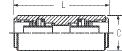

Note: Use with Air Brake Tubing see page 33.

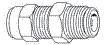
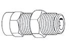

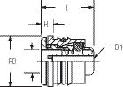
83 Tube Catalog DIA O.D. Number F L D1 D H 5/32 1861x2.5 0.38 0.62 0.12 .165 0.17 3/16 1861x3 0.44 0.62 0.12 .195 0.16 1/4 1861x4 0.56 0.65 0.13 .263 0.17 3/8 1861x6 0.69 0.81 0.22 .388 0.19 1/2 1861x8 0.81 0.83 0.34 .513 0.19 5/8 1861x10 0.97 0.99 0.40 .638 0.24 3/4 1861x12 1.12 0.99 0.52 .763 0.24
Tube Catalog Dia O.D. Number C L 5/32 1862x2.5 0.44 1.41 3/16 1862x3 0.44 1.62 1/4 1862x4 0.53 1.62 3/8 1862x6 0.69 1.94 1/2 1862x8 0.83 1.96 5/8 1862x10 0.96 2.51
Female Tube Thread Pipe Catalog Hex Hex O.D. T Thread Number C C1 L 1/4 9/16–24 1/4 1873x4x4 5/8 11/16 1.45 3/8 3/4–16 3/8 1873x6x6 7/8 15/16 1.59 1/2 1–14 1/2 1873x8x8 1 1-1/4 1.97
Tube Thread Catalog Hex Hex Max O.D. T Number C C1 L P 1/4 9/16–24 1874x4x4 5/8 11/16 1.62 0.47 3/8 3/4–16 1874x6x6 7/8 15/16 1.96 0.66 1/2 7/8–-14 1874x8x8 1 1 2.00 0.83 5/8 1–14 1874x10x10 1 1-1/4 2.42 1.00
Page 82
Brass Products
Quick>Connect Air Brake - Brass
SAE No. AA0102)
Note: Use with Air Brake Tubing see page 33.
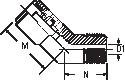

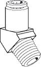

SAE No. AA0103)
84
Male Tube Pipe Catalog O.D Thread Number D1 L 5/32 1/16 1868x2.5x1 3/8 0.09 0.92 5/32 1/8 1868x2.5 7/16 0.25 0.92 3/16 1/8 1868x3 1/2 0.25 0.92 1/4 1/8 1868x4 9/16 0.19 0.95 1/4 1/4 1868x4x4 9/16 0.34 1.18 1/4 3/8 1868x4x6 11/16 0.41 1.17 3/8 1/8 1868x6x2 11/16 0.19 1.33 3/8 1/4 1868x6 11/16 0.31 1.29 3/8 3/8 1868x6x6 11/16 0.41 1.27 3/8 1/2 1868x6x8 7/8 0.53 1.47 1/2 1/4 1868x8x4 13/16 0.31 1.46 1/2 3/8 1868x8 13/16 0.41 1.35 1/2 1/2 1868x8x8 7/8 0.53 1.50 5/8 3/8 1868x10x6 1 0.41 1.72 5/8 1/2 1868x10 1 0.53 1.71 3/4 1/2 1868x12 1-1/16 0.53 1.72 Female Tube Pipe Catalog O.D. Thread Number L 1/4 1/8 1866x4 9/16 1.33 1/4 1/4 1866x4x4 11/16 1.58 3/8 1/8 1866x6x2 11/16 1.45 3/8 1/4 1866x6 11/16 1.69 3/8 3/8 1866x6x6 13/16 1.75 1/2 1/4 1866x8x4 13/16 1.66 1/2 3/8 1866x8 13/16 1.73 1/2 1/2 1866x8x8 1 1.97 Male
(Ref.
Female
(Ref.
Male Tube Pipe Catalog O.D Thread Number D1 M N 1/4 1/8 1880x4 0.19 0.95 0.59 1/4 1/4 1880x4x4 0.31 0.95 0.59 3/8 1/8 1880x6x2 0.25 1.05 0.48 3/8 1/4 1880x6 0.31 1.05 0.69 3/8 3/8 1880x6x6 0.41 1.10 0.63 3/8 1/2 1880x6x8 0.53 1.20 0.70 1/2 1/4 1880x8x4 0.31 1.07 0.88 1/2 3/8 1880x8 0.41 0.99 0.72 1/2 1/2 1880x8x8 0.53 0.99 0.82 5/8 3/8 1880x10x6 0.41 1.13 0.88 5/8 1/2 1880x10 0.53 1.26 0.92 3/4 1/2 1880x12 0.53 1.16 0.98
Connector
Connector
45° Male Elbow (Ref. SAE No. AA0302)
Page 83
Brass Products
Quick>Connect Air Brake - Brass
90° Male Elbow (Ref. SAE No. AA0302)
90° Male Elbow Long
Note: Use with Air Brake Tubing see page 33.
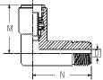
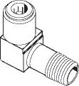
85 Tube Catalog O.D. Number M 1/4 1865x4 0.93 3/8 1865x6 1.15 1/2 1865x8 1.24 Male Tube Pipe Catalog O.D Thread Number D1 M N 1/4 1/8 1880x4S 0.13 0.82 0.60 7/16 1/4 1/4 1880x4x4S 0.22 0.98 0.60 9/16 3/8 1/8 1880x6x2S 0.13 1.20 0.68 7/16 3/8 1/4 1880x6S 0.22 1.20 0.89 9/16 3/8 3/8 1880x6x6S 0.30 1.20 0.97 11/16 1/2 1/4 1880x8x4S 0.23 1.20 0.97 9/16 1/2 3/8 1880x8S 0.30 1.04 1.07 11/16 1/2 1/2 1880x8x8S 0.42 1.08 1.22 7/8
90° Union Elbow (Ref. SAE No. AA0201)
Male Tube Pipe Catalog O.D Thread Number D1 M N 5/32 1/16 1869x2.5x1 0.13 0.75 0.59 5/32 1/8 1869x2.5 0.19 0.75 0.59 3/16 1/8 1869x3 0.19 0.84 0.69 3/16 1/4 1869x3x4 0.19 0.87 0.81 1/4 1/8 1869x4 0.19 0.92 0.68 1/4 1/4 1869x4x4 0.31 0.92 0.81 1/4 3/8 1869x4x6 0.41 1.03 0.83 3/8 1/8 1869x6x2 0.19 1.08 0.78 3/8 1/4 1869x6 0.31 1.13 0.96 3/8 3/8 1869x6x6 0.41 1.18 0.98 3/8 1/2 1869x6x8 0.53 1.27 1.07 1/2 1/4 1869x8x4 0.31 1.23 1.00 1/2 3/8 1869x8 0.41 1.25 0.98 1/2 1/2 1869x8x8 0.53 1.28 1.11 5/8 3/8 1869x10x6 0.41 1.44 1.09 5/8 1/2 1869x10 0.53 1.48 1.22 Male Tube Pipe
O.D. Thread Number D1 M N 3/8 1/4 1869x6L 0.31 1.21 1.55
45° Elbow - Swivel Male (Ref. SAE No. AA03DD) Swivel for installation purposes only.
Catalog
Page 84
Brass Products
Quick>Connect Air Brake - Brass
90° Swivel Male Elbow (Ref. SAE No. AA02DD)
Swivel for installation purposes only.
90° Female Elbow (Ref. SAE No. AA0203)
Union Tee (Ref. SAE No. AA0401)
Note: Use with Air Brake Tubing see page 33.
86 Male Tube Pipe Catalog O.D Thread Number D1 M N 1/4 1/8 1869x4S 0.14 0.89 0.88 7/16 1/4 1/4 1869x4x4S 0.23 0.99 1.06 9/16 1/4 3/8 1869x4x6S 0.30 0.99 1.06 11/16 3/8 1/8 1869x6x2S 0.74 1.03 0.97 7/16 3/8 1/4 1869x6S 0.23 1.12 1.14 9/16 3/8 3/8 1869x6x6S 0.30 1.12 1.15 11/16 3/8 1/2 1869x6x8S 0.42 1.18 1.40 7/8 1/2 1/4 1869x8x4S 0.22 1.08 1.20 9/16 1/2 3/8 1869x8S 0.30 1.13 1.27 11/16 1/2 1/2 1869x8x8S 0.42 1.25 1.47 7/8 5/8 3/8 1869x10x6S 0.42 1.35 1.34 11/16 5/8 1/2 1869x10S 0.42 1.38 1.54 7/8 Female Tube Pipe Catalog O.D Thread Number M N 1/4 1/8 1870x4 1.03 0.82 1/4 1/4 1870x4x4 1.04 0.76 3/8 1/8 1870x6x2 1.26 0.96 3/8 1/4 1870x6 1.28 1.09 3/8 3/8 1870x6x6 1.21 1.07 1/2 1/4 1870x8x4 1.25 1.11 1/2 3/8 1870x8 1.28 1.11 1/2 1/2 1870x8x8 1.36 1.07
Tube Catalog O.D. Number M 1/4 1864x4 0.93 3/8 1864x6 1.15 1/2 1864x8 1.22
Male Tube Pipe Catalog O.D Thread Number D1 M M1 N 1/4 1/8 1871x4 0.23 0.93 0.93 0.68 1/4 1/4 1871x4x4 0.32 0.93 0.93 0.83 3/8 1/4 1871x6 0.31 1.15 1.15 0.90 3/8 3/8 1871x6x6 0.41 1.15 1.14 0.90 3/8x1/4 1/4 1871x6x4x4 0.31 1.14 1.07 0.96 3/8 1/2 1871x6x8 0.53 1.09 1.08 1.11 1/2 3/8 1871x8 0.41 1.09 1.10 1.22
Male Run Tee (Ref. SAE No. AA0424)
Page 85
Brass Products
Quick>Connect Air Brake - Brass
Note: Use with Air Brake Tubing see page 33.

87 Male Tube Pipe Catalog O.D Thread Number D1 M M1 N 1/4 1/8 1871x4S 0.14 0.93 0.93 0.82 7/16 1/4 1/4 1871x4x4S 0.23 0.93 0.93 1.07 9/16 3/8 1/4 1871x6S 0.23 1.15 1.15 1.20 9/16 3/8 3/8 1871x6x6S 0.30 1.15 1.15 1.20 11/16 1/2 1/4 1871x8x4S 0.22 1.21 1.18 1.22 9/16 1/2 3/8 1871x8S 0.30 1.21 1.23 1.34 11/16 1/2 1/2 1871x8x8S 0.42 1.21 1.19 1.42 7/8
Male Tube Pipe Catalog O.D. Thread Number D1 M M1 N 3/16 1/8 1872x3 0.19 0.75 0.74 0.64 1/4 1/8 1872x4 0.19 0.93 0.93 0.64 1/4 1/4 1872x4x4 0.31 0.93 0.93 0.83 3/8 1/4 1872x6 0.31 1.15 1.15 0.91 3/8 3/8 1872x6x6 0.31 1.15 1.15 0.91 1/2 1/4 1872x8x4 0.31 1.22 1.22 0.98 1/2 3/8 1872x8 0.41 1.24 1.24 0.99 1/2 1/2 1872x8x8 0.53 1.22 1.22 1.12 Male
Male Tube Pipe Catalog O.D. Thread Number D1 M M1 N 1/4 1/8 1872x4S 0.14 0.93 0.93 0.80 7/16 1/4 1/4 1872x4x4S 0.23 0.93 0.93 1.04 9/16 3/8 1/8 1872x6x2S 0.13 1.15 1.15 0.94 7/16 3/8 1/4 1872x6S 0.23 1.15 1.15 1.14 9/16 3/8 3/8 1872x6x6S 0.30 1.15 1.15 1.17 11/16 1/2 1/4 1872x8x4S 0.22 1.23 1.23 1.21 9/16 1/2 3/8 1872x8S 0.30 1.24 1.24 1.24 11/16 1/2 1/2 1872x8x8S 0.42 1.21 1.19 1.42 7/8
Swivel Male Run Tee (Ref. SAE No. AA04EE) Swivel for installation purposes only.
Branch Tee (Ref. SAE No. AA0425)
Swivel Male Branch Tee (Ref. SAE No. AA04FF)
Female Tube Pipe Catalog O.D Thread Number M N 3/8 1/4 1877x6 1.19 0.78
Swivel for installation purposes only.
Female Branch Tee
Page 86
Brass Products
Quick > Connect Air Brake - Composite
45˚ Q-CAB Connection to Male Pipe
Note: Use with Air Brake Tubing see page 33.
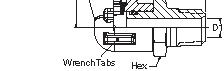
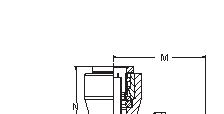
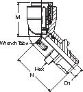
Special Fittings Fitting sizes and configurations other than shown above, can be provided. Please contact your Eaton Area Sales Manager for assistance.
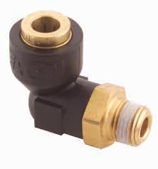
90˚
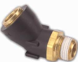
88
Tube Thread 45° Male Pipe O.D. Size Part# D1 M N Hex 1/4 1/8-27 217-35004-03 0.19 0.78 1.12 9/16 1/4 1/4-18 217-38404-03 0.28 0.78 1.30 9/16 1/4 3/8-18 217-38604-03 0.41 0.78 1.30 11/16 3/8 1/8-27 217-38206-03 0.19 1.00 1.11 3/4 3/8 1/4-18 217-35006-03 0.28 1.00 1.29 3/4 3/8 3/8-18 217-38606-03 0.41 1.00 1.29 3/4 1/2 1/4-18 217-38408-03 0.28 1.10 1.32 7/8 1/2 3/8-18 217-35008-03 0.41 1.10 1.26 7/8 1/2 1/2-14 217-38808-03 0.53 1.10 1.45 7/8 5/8 3/8-18 217-38610-03 0.41 1.34 1.30 1.0 5/8 1/2-14 217-35010-03 0.53 1.34 1.52 1.0
O.D. Size Part# D1 M N Hex 1/4 1/8-27 217-40004-03 0.19 1.11 0.86 9/16 1/4 1/4-18 217-43404-03 0.28 1.29 0.86 9/16 1/4 3/8-18 217-43604-03 0.41 1.29 0.86 11/16 3/8 1/8-27 217-43206-03 0.19 1.17 1.12 3/4 3/8 1/4-18 217-40006-03 0.28 1.36 1.12 3/4 3/8 3/8-18 217-43606-03 0.41 1.36 1.12 3/4 3/8 1/2-14 217-43806-03 0.53 1.61 1.12 7/8 1/2 1/4-18 217-43408-03 0.28 1.59 1.19 7/8 1/2 3/8-18 217-40008-03 0.41 1.40 1.19 7/8 1/2 1/2-14 217-43808-03 0.53 1.60 1.19 7/8 5/8 3/8-18 217-43610-03 0.41 1.46 1.46 1.0 5/8 1/2-14 217-40010-03 0.53 1.68 1.46 1.0
Tube Thread 90° Male Pipe
Q-CAB Connection to Male Pipe
Page 87
Brass Products
Quick>Connect Air Brake
Plugs,
1800T Collet Service Tool
The Collet Service Tool, made from sturdy plated steel, is designed to assist in field servicing O-Rings of Q-CAB fittings. Use the half moon radius section to pry up and remove the collet

Note: Use with Air Brake Tubing see page 33.

1800TRK Tube Release Kit
The 1800TRK tube release kit is designed to ease the removal of tubing from Q-CAB connectors. The individual tools are manufactured of a sturdy engineering
and use the movable piano wire to remove the O-Ring. Notches are used to mark the tubing with insertion depth in five tubing sizes.
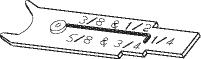

plastic. All seven tube sizes currently offered in Q-CAB can be serviced with the five tools that make up the 1800TRK kit.
Collet Repair Kits
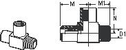
Consisting of a replacement collet and a replacement o-ring, the collet repair kits
provide an opportunity to repair damaged Q-CAB connectors.
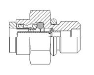
89 Male Female Tube Pipe Pipe Catalog O.D Thread Thread Number D1 M N M1 3/8 3/8 1/4 1883x6x6x4 0.41 1.28 1.00 0.95 1/4 1/4 1/4 117-550644-03 0.31 1.62 .94 0.75 Tube Catalog O.D Number 1/4 1829x4 3/8 1829x6 1/2 1829x8
Pressure
Adapter Tee Tube Repair Kit O.D. Part # 5/32 1800Kx2.5 3/16 1800Kx3 1/4 1800Kx4 3/8 1800Kx6 1/2 1800Kx8 5/8 1800Kx10 3/4 1800Kx12
(Nylon)
Male Female Tube Pipe Pipe Catalog O.D. Thread Thread Number D1 M 1/4 M12x1.5 217-2120403 11/16 .34 .94 Male Metric M D1 Page 88
Brass Products
Air Brake - Nylon Tubing
Typical Application: Air brake systems except where temperatures exceed +200°F or where battery acid can drip on tubing.
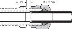
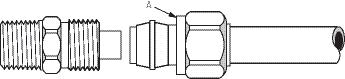
Pressure: Maximum operating pressure of 150 psi.
Vibration: Fair resistance.
Temperature Range: -40°F to +200°F (-40°C to +93°C)
Material: CA360 Brass.
Used With: Air Brake Tubing. See Page 33
Advantages: Easy to assemble (no tube preparation or flaring required.) Built in tube support. May be used with copper tubing by replacing nut, sleeve and insert with long nut and spherical sleeve. Insert should be removed for copper tubing use. See page 96 for details.
Note: For additional technical questions, contact Technical Support at 1-888-258-0222.
Refer to safety information regarding proper selection of tubing and tube connectors on page 5.
Conformance: Meets specifications and standards of SAE and DOT FMVSS 571.106.
How to Order: For complete assemblies (body, nuts and sleeves), order by catalog number. Example: 1468x4x4. To order body only (less nut and sleeve), add prefix “B” to catalog number and change “14” to “13”. Example: B1368x4x4. Nuts, sleeve and insert can be ordered separately by catalog number.
To order complete assembly with pipe sealant (Seal-AThread), add suffix “Z” to catalog number. Example: 1468x4x4Z (special order only).
To order complete assembly with gauge ring, add suffix “K” to catalog number. Example: 1468x4x4K (special order only).
Note: Refer to current price list for availability of cataloged items. Quotations and delivery of non-stock items supplied on request. Configurations and dimensions subject to change without notice. Additional information can be found in SAE J246.
Assembly Instructions:
1. Cut tubing to desired length.
2. Slide nut and then sleeve on tubing. Threaded end of nut “A” must face toward connector body.
3. Insert tubing into the pre assembled fitting. Be sure tubing is bottomed in connector.
4. Tighten nut to required torque as indicated on chart. Another check on proper assembly is dimension A also noted on chart. A gauge ring also assures installation to specification. See page 95.
Disassembly:
Remove nut and pull tubing out of connector body. Insert will remain in tubing.
Reassembly: Push tubing and insert into connector body until it bottoms. Thread nut onto connector body and torque as in Step 4. Label Set:
FS-900 (adhesive) CL-497 (non-adhesive)
90
Tube A Size Torque Dimension 1/4 85 to 115 in. lbs. .085/.105 3/8 12 to 17 ft. lbs. .125/.145 1/2 25 to 33 ft. lbs. .100/.120 5/8 26 to 35 ft. lbs. .115/.135 3/4 38 to 50 ft. lbs. .180/.200
Tube O.D. 1/4 3/8 1/2 5/8 3/4 Thread Size-B 7/16–24 17/32–24 11/16–20 13/16–18 1–18
Page 89
Brass Products
Air Brake - Nylon Tubing
Note: Use with Air Brake Tubing see page 33.


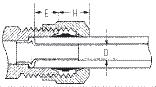
91 Tube Catalog DIA. O.D Number C D L 1/4 1460x4 .359 .256 .300 3/8 1460x6 .479 .384 .390 1/2 1460x8 .625 .509 .430 5/8 1460x10 .745 .635 .480 3/4 1460x12 .922 .760 .530 Sleeve (Ref. SAE No. 100115) Tube E O.D Tube Stop H* D 1/4 0.20 0.32 .133 3/8 0.26 0.42 .215 1/2 0.39 0.45 .340 5/8 0.39 0.48 .398 3/4 0.51 0.50 .523 *H is hand tight dimensions. Tube Catalog O.D Number D L 1/4 1461x4 9/16 .256 .450 3/8 1461x6 5/8 .384 .630 1/2 1461x8 13/16 .509 .720 5/8 1461x10 15/16 .634 .770 3/4 1461x12 1-1/8 .760 .810 Nut (Ref. SAE No. 100110) Tube Catalog O.D. Number L 1/4 1462x4 7/16 0.85 3/8 1462x6 9/16 1.10 1/2 1462x8 11/16 1.31 5/8 1462x10 13/16 1.43 3/4 1462x12 1 1.60 Union (Ref.
SAE No. 100101BA)
Page 90
Brass Products
Air Brake - Nylon Tubing
Male Connector (Ref. SAE No. 100102BA)


Female Connector (Ref. SAE No. 100103BA)
Bulkhead Union
Note: Use with Air Brake Tubing see page 33.
45° Male Elbow (Ref. SAE No. 100302BA)

92 Tube Male Pipe Catalog O.D. Thread Number D1 L 1/4 1/16 1468x4x1 7/16 .125 .90 1/4 1/8 1468x4 7/16 .188 .88 1/4 1/4 1468x4x4 9/16 .188 1.09 1/4 3/8 1468x4x6 11/16 .188 1.12 3/8 1/8 1468x6x2 9/16 .188 1.02 3/8 1/4 1468x6 9/16 .312 1.20 3/8 3/8 1468x6x6 11/16 .312 1.23 3/8 1/2 1468x6x8 7/8 .312 1.42 1/2 1/4 1468x8x4 11/16 .312 1.32 1/2 3/8 1468x8 11/16 .406 1.32 1/2 1/2 1468x8x8 7/8 .406 1.51 1/2 3/4 1468x8x12 1-1/16 .406 1.57 5/8 3/8 1468x10x6 13/16 .406 1.38 5/8 1/2 1468x10 7/8 .531 1.57 5/8 3/4 1468x10x12 1-1/16 .750 1.63 3/4 1/2 1468x12 1 .531 1.67 3/4 3/4 1468x12x12 1-1/16 .660 1.70 Tube Fem. Pipe Catalog O.D Thread Number L 1/4 1/8 1466x4 9/16 0.85 3/8 1/8 1466x6x2 9/16 1.01 3/8 1/4 1466x6 11/16 1.19 3/8 3/8 1466x6x6 7/8 1.19 1/2 3/8 1466x8 7/8 1.28 MTO - Made To Order Tube Catalog Max. O.D. Number L P 1/4 1474x4 9/16 1.38 0.25 3/8 1474x6 11/16 1.62 0.25 1/2 1474x8 13/16 1.88 0.25 MTO - Made To Order Tube Male Pipe Catalog O.D Thread Number D1 M N 1/4 1/8 1480x4 .188 0.50 0.64 1/4 1/4 1480x4x4 .312 0.61 0.86 3/8 1/4 1480x6 .312 0.72 0.86 3/8 3/8 1480x6x6 .406 0.76 0.95 1/2 1/4 1480x8x4 .312 0.85 0.95 1/2 3/8 1480x8 .406 0.85 0.95 1/2 1/2 1480x8x8 .531 0.88 1.17 5/8 1/2 1480x10 .531 0.95 1.17
Page 91
Brass Products
Air Brake - Nylon Tubing
Note: Use with Air Brake Tubing see page 33.


93 Tube Catalog O.D. Number M 1/4 1465x4 0.63 3/8 1465x6 0.80 1/2 1465x8 0.94 5/8 1465x10 1.10 MTO - Made To Order Union Elbow (Ref. SAE No. 100201BA) Tube Male Pipe Catalog O.D. Thread Number D1 M N 1/4 1/8 1469x4 .188 0.63 0.67 1/4 1/4 1469x4x4 .312 0.69 0.88 1/4 3/8 1469x4x6 .406 0.74 0.87 3/8 1/8 1469x6x2 .188 0.73 0.75 3/8 1/4 1469x6 .312 0.80 0.93 3/8 3/8 1469x6x6 .406 0.85 0.92 3/8 1/2 1469x6x8 .562 0.95 1.11 1/2 1/4 1469x8x4 .313 0.87 1.00 1/2 3/8 1469x8 .407 0.94 1.00 1/2 1/2 1469x8x8 .531 1.04 1.19 5/8 3/8 1469x10x6 .406 1.01 1.06 5/8 1/2 1469x10 .531 1.10 1.25 5/8 3/4 1469x10x12 .750 1.21 1.30 3/4 1/2 1469x12 .531 1.20 1.34
(Ref.
Tube Male Pipe Catalog O.D. Thread Number D1 M N 3/8 14 1469x6L .312 0.80 1.44 1/2 3/8 1469x8L .406 0.94 1.38
(Ref.
Tube Fem. Pipe Catalog O.D Thread Number M N 1/4 1/8 1470x4 0.72 0.54 3/8 1/4 1470x6 0.90 0.78 1/2 3/8 1470x8 1.04 0.83 MTO - Made To Order
90° Male Elbow
SAE No. 100202BA)
90° Male Elbow - Long
SAE No. 100202BA)
90° Female Elbow (Ref. SAE No. 100203BA)
Page 92
Brass Products
Air Brake - Nylon Tubing
Union Tee (Ref. SAE No. 100401BA)
Dimensions read left, right, center.
Male Branch Tee (Ref. SAE No. 100425BA)
Female Branch Tee
Male Run Tee (Ref. SAE No. 100424BA)
Note: Use with Air Brake Tubing see page 33.
94 Tube Catalog O.D Number M M1 M2 1/4 1464x4 0.64 0.64 0.64 3/8x3/8x1/4 1464x6x6x4 0.72 0.72 0.69 3/8 1464x6 0.80 0.80 0.80 1/2x1/2x3/8 1464x8x8x6 0.86 0.86 0.85 1/2 1464x8 0.94 0.94 0.94 Tube Male Pipe Catalog O.D Thread Number D1 M M1 N 1/4 1/8 1472x4 .188 0.63 0.63 0.67 3/8x1/4 1/4 1472x6x4x4 .312 0.82 0.69 0.93 3/8 1/8 1472x6x6x2 .188 0.73 0.73 0.75 3/8 1/4 1472x6 .312 0.82 0.82 0.93 3/8 3/8 1472x6x6x6 .406 0.85 0.85 0.92 1/2x3/8 3/8 1472x8x6x6 .406 0.94 0.85 1.00 1/2 1/4 1472x8x8x4 .312 0.94 0.94 1.00 1/2 3/8 1472x8 .406 0.94 0.94 1.00 MTO - Made To Order Tube Fem. Pipe Catalog O.D Thread Number M N 3/8 1/4 1477x6 0.90 0.78 1/2 1/4 1477x8x8x4 0.97 0.83 5/8 1/4 1477x10x10x4 1.04 0.89 MTO - Made To Order Tube Male Pipe Catalog O.D. Thread Number D1 M M1 N 1/4 1/8 1471x4 .188 0.64 0.64 0.67 3/8x1/4 1/4 1471x6x4x4 .312 0.80 0.69 0.93 3/8 1/4 1471x6 .312 0.80 0.80 0.93 3/8 3/8 1471x6x6x6 .406 0.85 0.85 0.92 1/2 3/8 1471x8 .406 0.94 0.94 1.10 MTO - Made To Order
Page 93
Brass Products
Air Brake - Nylon Tubing
Gauge Ring
Nut screwed to Gauge Ring assures installation to specifications.
Note:
Use with Air Brake Tubing see page 33.

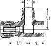

95 Tube Fem. Pipe Male Pipe Catalog O.D. Thread Thread Number D1 M N N1 3/8 1/4 1/4 1482x6x4x4 .312 0.88 0.75 0.94 MTO - Made To Order Adapter Tee Tube Catalog O.D. Number A B C D 1/4 1484x4 0.64 0.46 .163 .133 3/8 1484x6 0.76 0.58 .245 .215 1/2 1484x8 0.94 0.76 .370 .340 5/8 1484x10 1.06 0.84 .434 .398 3/4 1484x12 1.21 1.00 .559 .523 Insert (Brass) Tube Catalog O.D Number L 1/4 1485x4 .085/.105 3/8 1485x6 .125/.145 1/2 1485x8 .100/.120 5/8 1485x10 .115/.135 3/4 1485x12 .180/.200
Page 94
Brass Products
Air Brake - Copper Tubing
Note: For additional technical questions, contact Technical Support at 1-888-258-0222.
Refer to safety information regarding proper selection of tubing and tube connectors on page 5.
Typical Application: Air brake systems.
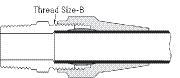
Pressure: Maximum operating pressure of 150 psi.
Vibration: Fair resistance.
Temperature Range: -65°F to +250°F (-53°C to +121°C) with copper tubing.
Material: CA360 Brass.
Used With: Copper tubing in air brake systems.
Advantages: Easy to assemble (no flaring). May be used with nylon tubing by replacing long nut and spherical sleeve with insert, rigid sleeve and nut.
Conformance:
Meets specifications and standards of SAE and DOT.
How to Order:
For complete assemblies For complete assemblies (body, nuts and sleeves), order by catalog number. Example: 1368x4. To order body only (less nut and sleeve), add prefix “B” to catalog number. Example: B1368x4. Nuts and sleeve can be ordered separately by catalog number.
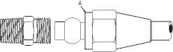
To order complete assembly with pipe sealant (Seal-AThread), add suffix “Z” to catalog number. Example: 1368x4Z (special order only). Note: Refer to current price list for availability of cataloged items. Quotations and delivery of non-stock items supplied on request. Configurations and dimensions subject to change without notice. Additional information can be found in SAE J246.
Assembly Instructions:
1. Cut tubing to desired length. Make sure all burrs are removed and the ends are cut square.
2. Slide nut and then sleeve on tubing. Threaded end of nut “A” must face toward connector body.
3. Insert tubing into connector. Be sure tubing is bottomed on fitting shoulder.
4. Thread nut onto connector body until it is hand tight.
5. From that point, tighten with a wrench the number of turns indicated in the chart below.
Label Set: FS-800 (adhesive) CL-491 (non-adhesive)
96 Tube O.D. 1/4 3/8 1/2 5/8 3/4 1 Thread Size-B 7/16–24 17/32–24 11/16–20 13/16–18 1–18 1-1/4-16
Additional Tube Number Of Turns Size From Hand Tight 1/4, 3/8 1-3/4 1/2, 5/8, 3/4 3-1/4
Page 95
Brass Products
Air Brake - Copper Tubing

H is hand tight dimensions.
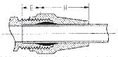
SAE No. 120101BA)
Male Connector (Ref. SAE No. 120102BA)
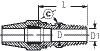
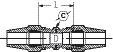

97 Tube E O.D. Tube Depth H 1/4 0.25 0.58 3/8 0.31 0.87 1/2 0.44 0.95 5/8 0.44 1.05 3/4 0.56 1.25 Tube Male Pipe Catalog O.D Thread Number C D D1 L 1/4 1/8 1368x4 7/16 .188 .188 0.88 1/4 1/4 1368x4x4 9/16 .188 .188 1.09 3/8 1/8 1368x6x2 9/16 .312 .188 1.02 3/8 1/4 1368x6 9/16 .312 .312 1.20 3/8 3/8 1368x6x6 11/16 .312 .406 opt. 1.23 3/8 1/2 1368x6x8 7/8 .312 .531 opt. 1.42 1/2 1/4 1368x8x4 11/16 .406 .312 1.32 1/2 3/8 1368x8 11/16 .406 .406 1.32 1/2 1/2 1368x8x8 7/8 .406 .531 opt. 1.51 5/8 3/8 1368x10x6 13/16 .531 .406 1.38 5/8 1/2 1368x10 7/8 .531 .531 1.57 3/4 1/2 1368x12 1 .656 .531 1.67 3/4 3/4 1368x12x12 1-1/16 .656 .719 opt. 1.70 Tube Catalog O.D. Number D F L 1/4 1360x4 .255 .322 .250 3/8 1360x6 .382 .461 .313 1/2 1360x8 .507 .594 .375 5/8 1360x10 .632 .734 .438 3/4 1360x12 .758 .874 .500 Sleeve (Ref. SAE No. 120115) Tube Catalog O.D Number C D L 1/4 1361x4 9/16 .256 0.75 3/8 1361x6 5/8 .384 1.13 1/2 1361x8 13/16 .509 1.25 5/8 1361x10 15/16 .634 1.38 3/4 1361x12 1-1/8 .760 1.56 Nut (Ref. SAE No. 120111) Tube Catalog O.D. Number C D L 1/4 1362x4 7/16 .188 0.85 3/8 1362x6 9/16 .312 1.10 1/2 1362x8 11/16 .406 1.31 5/8 1362x10 13/16 .531 1.43 3/4 1362x12 1 .656 1.60 1 1362x16 1-1/4 .875 1.78 Union
(Ref.
Page 96
Brass Products
Air Brake - Copper Tubing
Female Connector (Ref. SAE No. 120103BA)
45° Male Elbow (Ref. SAE No. 120302BA) 90° Male Elbow (Ref. SAE No. 120202BA)

98 Tube Fem. Pipe Catalog O.D. Thread Number C D L 3/8 1/4 1366x6 11/16 .312 1.19 3/8 3/8 1366x6x6 7/8 .312 1.19 1/2 3/8 1366x8 7/8 .406 1.28 Tube Male Pipe Catalog O.D. Thread Number D D1 M N 3/8 1/4 1380x6 .312 .312 0.72 0.86 3/8 3/8 1380x6x6 .312 .406 0.76 0.95 1/2 3/8 1380x8 .409 .406 0.85 0.95 5/8 1/2 1380x10 .534 .531 0.95 1.17 Tube Male Pipe Catalog O.D. Thread Number D D1 M N 1/4 1/8 1369x4 .188 .188 0.63 0.67 1/4 1/4 1369x4x4 .190 .312 0.69 0.88 3/8 1/8 1369x6x2 .312 .188 0.73 0.75 3/8 1/4 1369x6 .317 .312 0.80 0.93 3/8 3/8 1369x6x6 .317 .406 0.85 0.92 3/8 1/2 1369x6x8 .317 .562 0.95 1.11 1/2 1/4 1369x8x4 .409 .313 0.87 1.00 1/2 3/8 1369x8 .409 .409 0.94 1.00 1/2 1/2 1369x8x8 .409 .531 1.04 1.19 5/8 3/8 1369x10x6 .534 .406 1.01 1.06 5/8 1/2 1369x10 .534 .531 1.10 1.25
Tube Male Pipe Catalog O.D. Thread Number D M N 3/8 1/4 1369x6L .312 0.81 1.44 1/2 3/8 1369x8L .406 1.25 1.38
90° Male Elbow - Long
Page 97
Brass Products
Air Brake - Copper Tubing
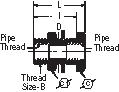
99 Tube Catalog O.D. Number M M1 D D1 3/8 1364x6 0.80 0.80 .314 .314 1/2 1364x8 0.94 0.94 .406 .406 Union Tee (Ref. SAE No. 120401BA) Tube Male Pipe Catalog O.D. Thread Number D M M1 N 3/8 1/4 1371x6 .312 0.80 0.80 0.93 3/8 3/8 1371x6x6x6 .406 0.85 0.85 0.92 Male Run Tee (Ref. SAE No. 120424BA) Tube Tube Male O.D. O.D. Pipe Catalog A B Thread Number D M N 3/8 3/8 1/4 1372x6 .312 0.82 0.93 3/8 3/8 3/8 1372x6x6x6 .406 0.85 0.92 1/2 1/2 3/8 1372x8 .406 0.94 1.00 Male Branch Tee (Ref. SAE No. 120425BA) Fem. Pipe Catalog Thread Thread Thread Size B C C1 D I L 1/4 1344 3/4–16 1 15/16 .422 1.25 1.50 1/4 1345 3/4–16 1 15/16 .422 0.69 0.94 3/8 1346 1–14 1-1/8 1-3/8 .563 1.06 1.31 1/2 1351 1-1/8–14 1-1/4 1-3/8 .703 1.19 1.50 Bulkhead Coupling (Brass)
Page 98
Brass Products
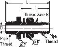
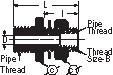
Air Brake - Copper Tubing


100 Male Fem. Pipe Pipe Catalog Thread Thread Thread Number Size B C D I L 1/2 1/4 1340 3/4–16 1-1/4 15/16 .312 1.13 2.16 1/2 1/4 1341 3/4–16 1-1/4 15/16 .312 1.53 2.53 Bulkhead Coupling (Brass) Male Fem. Pipe Pipe Catalog Thread Thread Thread Number Size B C D I L 1/2 1/4 1342 1–14 1-1/4 1-3/8 .375 1.88 2.94 1/2 1/4 1343 1–14 1-1/4 1-3/8 .375 2.88 3.94 Bulkhead Coupling (Brass) Male Pipe Catalog Thread Number D L 1/4 W15310 .188 1.56 Draincock Male Fem. Pipe Pipe Catalog Thread Thread Number C D L 1/4 1/4 W20332 5/8 3/4 .218 1.81 Shut Off Valve Male Pipe Catalog Thread Number C L 1/4 145 9/16 1.00 External Seat Draincock Rating: 125 psi with one 1/4" bubble in 5 seconds permissible key leakage. D L D L C C1
C1 C1 C1 Page 99
Brass Products
Threaded Sleeve
Typical Application: Oil, air, water and lubrication systems.
Pressure: Operating pressure of 500 psi for 1/8” to 1/4” sizes, 250 psi for 5/16” and 3/8” sizes.
Vibration: Fair resistance.
Temperature Range: -65°F to +250°F (-53°C to +121°C) range at maximum operating pressures.
Material: CA360 Brass.
Used With: Aluminum and copper tubing. Not recommended for steel tubing.
Advantages: Easy to assemble, no flaring. Two (2) piece construction.
Conformance: Meets ASA and ASME specifications. How to Order: Order individually by catalog number.
Note: Refer to current price list for availability of cataloged items. Quotations and delivery of non-stock items supplied on request. Configurations and dimensions subject to change without notice.
Note: For additional technical questions, contact Technical Support at 1-888-258-0222.
Assembly Instructions:
1. Cut tubing to desired length.
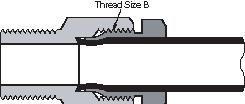
2. Slide nut on end of tube. Threaded end “A” of nut must face toward connector.
Note:
The lead end of nut incorporates the sleeve as a single piece.
3. Insert tube into connector body. Be sure tube is bottomed on connector shoulder.
4. Lubricate threads and assemble nut to connector body
5. From that point, tighten Tighten nut, hand tight. From hand tight, tighten with a wrench 1-1/2 additional turns to form proper seal.
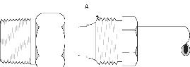
101 / Tube O.D. 1/8 3/16 1/4 5/16 3/8 Thread Size-B 5/16–24 3/8–24 7/16–24 1/2–20 9/16–20
Thread Size B
Page 100
Brass Products
Threaded Sleeve

*Thread Size 1/4-28 Tapered Male Thread.


102 Tube Catalog O.D. Number C D L 1/8 6100x2 3/8 .130 0.50 3/16 6100x3 7/16 .193 0.53 1/4 6100x4 1/2 .255 0.56 5/16 6100x5 9/16 .318 0.61 3/8 6100x6 5/8 .380 0.61 MTO - Made To Order Nut Tube Male Pipe Catalog O.D Thread Number C D L 1/8 1/8 6200x2 7/16 .078 0.62 1/8 * 6200x2x21 7/16 .080 0.62 3/16 1/8 6200x3 7/16 .141 0.69 1/4 1/8 6200x4 1/2 .188 0.75 5/16 1/8 6200x5 9/16 .219 0.89 3/8 1/4 6200x6 5/8 .312 0.97 *Thread Size 1/4-28 Tapered Male Thread. MTO - Made To Order Male Connector Tube Male Pipe Catalog O.D Thread Number D D1 M N 1/8 1/8 6400x2 .073 .125 0.50 0.66 1/8 * 6400x2x21 .078 .080 0.50 0.52 3/16 1/8 6400x3 .141 .156 0.56 0.62 1/4 1/8 6400x4 .188 .188 0.52 0.62
Male Elbow
Page 101
Brass Products Pipe
Typical Application: Grease, refrigeration, instrumentation and hydraulic systems. Fuel, LP and natural gas available on special order.
Pressure: Operating pressure up to 1200 psi.
Vibration: Fair resistance.
Temperature Range: -65°F to +250°F (-53°C to +121°C).
Material: CA360 Brass.
Used With: Brass, bronze and iron pipe.
Advantages: Dryseal pipe threads (NPTF). Large range of sizes and configurations.
Conformance: Listed by Underwriters Laboratories (available on special order) for fuel equipment, refrigeration and gas. Meets specifications and standards of ASA, ASME and SAE.
How to Order: Order individually by catalog number. Example: 3325x4. To order with pipe sealant (Seal-A-Thread), add a “Z” suffix to the catalog number. (Special order only). Example: 3325x4Z.
Note: Refer to current price list for availability of cataloged items. Quotations and delivery of non-stock items supplied on request. Configurations and dimensions subject to change without notice. Additional information can be found in SAE J530 Automotive Pipe Fittings and SAE J531 Drain Plugs.
Note: For additional technical questions, contact Technical Support at 1-888-258-0222.
Assembly Instructions:
1. Tighten approximately 2-1/2 turns past hand tight.
2. Connectors with Seal-AThread tighten two turns past hand tight. Brittle materials require special cautions.
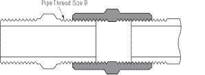
Label Set: W-8022 (adhesive) CL-490 (non-adhesive)
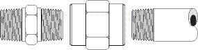
103 Pipe Size 1/16 1/8 1/4 3/8 1/2 3/4 Thread Size-B 1/16–27 1/8–27 1/4–18 3/8–18 1/2–14 3/4–14
Pipe Thread Size B
Page 102
Brass Products Pipe


104 Fem. Pipe Catalog Thread Number C L 1/8* 3129x2 9/16 .50 1/4* 3129x4 11/16 .59 3/8* 3129x6 13/16 .68 *PTF Short Thread Cap Male Pipe Catalog Thread Number E L 1/8* 3150x2 .05 .28 1/4* 3150x4 .08 .42 3/8* 3150x6 .09 .43 *PTF Short Thread Slotted Plug Male Pipe Catalog Thread Number C F L 1/8* 3152x2 7/16 .19 .57 1/4* 3152x4 9/16 .18 .62 3/8* 3152x6 11/16 .22 .72 1/2* 3152x8 7/8 .22 .78 3/4** 3152x12 1-1/16 .25 .88 *PTF Short Thread **PTF Special Short Thread Hex Head Plug Male Pipe Catalog Socket Thread Number Hex L 1/8 3153x2 3/16 .270 1/4 3153x4 1/4 .410 3/8 3153x6 5/16 .410 1/2 3153x8 3/8 .540 MTO - Made To Order Hex Socket Plug Fem. Male Pipe Pipe Catalog Thread Thread Number C D L 1/8 1/8 3200x2 9/16 .219 .88 1/4 1/8 3200x4x2 3/4 .219 1.06 1/4 1/4 3200x4 3/4 .312 1.25 3/8 1/4 3200x6x4 7/8 .312 1.25 3/8 3/8 3200x6 7/8 .438 1.25 1/2 3/8 3200x8x6 1-1/16 .438 1.47 3/4 3/8 3200x12x6 1-1/4 .438 1.59 3/4 1/2 3200x12x8 1-1/4 .562 1.69 Adapter
Male Pipe Catalog Square Thread Number C F L 1/8* 3151x2 .28 .24 .58 1/4* 3151x4 .37 .29 .74 3/8* 3151x6 .43 .32 .82 1/2* 3151x8 .56 .39 .99 3/4* 3151x12 .62 .43 1.12 *PTF Short Thread Square Head Plug
(Ref. SAE No. 130139)
Page 103
Brass Products Pipe
SAE No. 130140)
No. 130138)
Restriction Pipe Adapter (With .0625 Orifice)


Note: Other orifice sizes available (special order only).

105 Male Fem. Pipe Pipe Catalog Thread Thread Number C D L 1/4* 1/8 3220x4x2 5/8 .339 0.59 3/8 1/8 3220x6x2 11/16 .328 0.75 3/8* 1/4 3220x6x4 11/16 .438 0.69 1/2* 1/8 3220x8x2 7/8 .530** 0.75 1/2* 1/4 3220x8x4 7/8 .438** 0.75 1/2* 3/8 3220x8x6 7/8 .562 0.75 3/4* 3/8 3220x12x6 1-1/8 .562 0.88 3/4* 1/2 3220x12x8 1-1/8 .703 0.88 *PTF Short Thread **Optional Counterbore Bushing (Ref.
Fem. Pipe Catalog Thread Number C D L 1/4* 3250x4 1-1/16 .438 1.31 1/2 3250x8 1-9/16 .703 1.81 *PTF Short Thread Fem. Pipe Catalog Thread Number C D L 1/16 3300x1 7/16 .339 0.75 1/8 3300x2 9/16 .339 0.75 1/4 3300x4 3/4 .438 1.12 3/8 3300x6 7/8 .578 1.12 1/2 3300x8 1-1/16 .703 1.50 3/4 3300x12 1-1/4 .906 1.53 Fem. Fem. Pipe Pipe Thread Thread Catalog A A1 Number C D L 1/4 1/8 3300x4x2 3/4 .339 0.96 3/8 1/8 3300x6x2 7/8 .339 0.94 3/8 1/4 3300x6x4 7/8 .438 1.16 1/2 3/8 3300x8x6 1-1/16 .562 1.38 Union Coupling (Ref. SAE
Male Female Pipe Pipe Catalog Thread Thread Number C D L 1/8 1/8* 1512 1/2 .0625 0.75 *PTF Short Thread Reducer
(Ref. SAE
No. 130138)
Coupling
Page 104
Brass Products Pipe
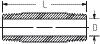


106 Male Male Pipe Pipe Thread Thread Catalog A A1 Number C D D1 L 1/16 1/16 3325x1 3/8 .125 .125 .978 1/8 1/16 3325x2x1 7/16 .230 .156 .955 1/8 1/8 3325x2 7/16 .219 .219 0.97 1/4 1/8 3325x4x2 9/16 .219 .219* 1.19 1/4 1/4 3325x4 9/16 .312 .312 1.38 3/8 1/8 3325x6x2 11/16 .219 .438 1.22 3/8 1/4 3325x6x4 11/16 .312 .438 1.41 3/8 3/8 3325x6 11/16 .438 .438 1.41 1/2 1/2 3325x8 7/8 .562 .562 1.81 3/4 3/4 3325x12 1-1/16 .750 .750 1.94 *Optional .312 Counterbore on 1/4" side.
Hex Nipple
Male Pipe Catalog Thread Number D L 1/8 3326x2 .281 0.75 1/4 3326x4 .375 0.88 3/8 3326x6 .500 1.00 1/2 3326x8 .625 1.12 3/4 3326x12 .750 1.38 Male Pipe Catalog Thread Number D L 1/8 3327x2 .281 1.50 1/8 3328x2 .281 2.00 1/8 3329x2 .281 2.50 1/8 3330x2 .281 3.00 1/8 3331x2 .281 3.50 1/4 3327x4 .375 1.50 1/4 3328x4 .375 2.00 1/4 3329x4 .375 2.50 1/4 3330x4 .375 3.00 1/4 3331x4 .375 3.50 3/8 3327x6 .480 1.50 3/8 3328x6 .490 2.00 3/8 3329x6 .480 2.50 3/8 3330x6 .480 3.00 3/8 3331x6 .480 3.50 1/2 3328x8 .625 2.00 1/2 3329x8 .625 2.50 1/2 3330x8 .625 3.00 3/4 3328x12 .750 2.00 3/4 3329x12 .750 2.50 MTO - Made To Order Close Nipple Long Nipple
(Ref. SAE No. 130137)
Page 105
Brass Products Pipe
*PTF short thread. **PTF special short thread.
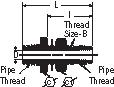
107 Male Fem. Pipe Pipe Catalog Thread Thread Number C D N N1 1/8 1/8 3350x2 9/16 .219 0.50 0.38 1/4 1/4 3350x4 11/16 .312 0.74 0.56 3/8 3/8 3350x6 13/16 .438 0.78 0.56 1/2 1/2 3350x8 1 .562 1.00 0.75 3/4 3/4 3350x12 1-1/4 .750 1.06 0.75 Fem. Male Pipe Pipe Catalog Thread Thread Number C D E N N1 1/8 1/8 3400x2 9/16 .219 0.25 0.66 0.47 1/8* 1/8** 3400x2W 1/2 .188 0.25 0.57 0.34 1/4 1/8 3400x4x2 11/16 .219 – 0.72 0.53 1/4* 1/4** 3400x4W 11/16 .266 0.36 0.78 0.45 1/4 1/4 3400x4 11/16 .312 – 0.91 0.72 3/8 3/8 3400x6 13/16 .438 – 0.98 0.72 1/2 1/2 3400x8 1 .562 – 1.25 1.04 3/4 3/4 3400x12 1-1/4 .750 – 1.38 1.12
45° Street Elbow (Ref. SAE No. 130339)
Male Fem. Pipe Pipe Catalog Thread Thd. Thd. Number Size B C D I L 1/2 1/4 1342 1–14 1-1/4 1-3/8 .375 1.88 2.94 1/2 1/4 1343 1–14 1-1/4 1-3/8 .375 2.88 3.94 Bulkhead Coupling (Brass) Fem. Pipe Catalog Thread Thread Number Size B C D I L 1/4 1344 3/4–16 1 15/16 .422 1.25 1.50 1/4 1345 3/4–16 1 15/16 .422 0.69 0.94 3/8 1346 1–14 1-1/8 1-3/8 .563 1.06 1.31 1/2 1351 1-1/8–14 1-1/4 1-3/8 .703 1.19 1.50 Bulkhead Coupling (Brass) Male Fem. Pipe Pipe Catalog Thread Thd. Thd. Number Size B C D I L 1/2 1/4 1340 3/4–16 1-1/4 15/16 .312 1.13 2.16 1/2 1/4 1341 3/4–16 1-1/4 15/16 .312 1.53 2.53 Bulkhead Coupling (Brass)
90° Street Elbow (Ref. SAE No. 130239)
C1 C1 C1 Page 106
Brass Products Pipe
90° Elbow (Ref. SAE No. 130238)

108 Fem. Pipe Catalog Thread Number C D N 1/8 3500x2 9/16 .339 0.55 1/4 3500x4 11/16 .438 0.78 3/8 3500x6 3/4 .562 0.84 1/2 3500x8 1 .703 1.09 3/4 3500x12 1-1/4 .891 1.16
Fem. Male Pipe Pipe Catalog Thread Thread Number C D L L2 N 1/8 1/8 3600x2 9/16 .219 1.10 0.55 0.67 1/4 1/4 3600x4 11/16 .312 1.56 0.78 0.91 3/8 3/8 3600x6 13/16 .438 1.68 0.84 0.97 1/2 1/2 3600x8 1 .562 2.18 1.09 1.25 3/4 3/4 3600x12 1-1/4 .750 2.32 1.16 1.38 Male
Tee
Fem. Pipe Catalog Thread Number C D L L2 1/8 3700x2 9/16 .339 1.10 0.55 1/4 3700x4 11/16 .438 1.56 0.78 3/8 3700x6 13/16 .562 1.68 0.84 1/2 3700x8 1 .703 2.18 1.09 3/4 3700x12 1-1/4 .906 2.32 1.16 Tee (Ref. SAE No. 130438) Fem. Male Pipe Pipe Catalog Thread Thread Number C D M N 1/8 1/8 3750x2 9/16 .219 0.55 0.67 1/4 1/4 3750x4 11/16 .312 0.78 0.92 3/8 3/8 3750x6 13/16 .438 0.84 0.97 1/2 1/2 3750x8 1 .562 1.09 1.27 3/4 3/4 3750x12 1-1/4 .750 1.16 1.38 Male Run Tee (Ref. SAE No. 130424) Fem. Pipe Catalog Thread Number C D M 1/8 3950x2 1/2 .339 0.50 1/4 3950x4 11/16 .438 0.75 3/8 3950x6 7/8 .562 0.81 1/2 3950x8 1 .703 1.09 Cross
Branch
(Ref. SAE No. 130425)
Page 107
Brass Products Pipe
109
Straight SAE J2044 90° Elbow SAE J2044 Male Pipe Thread Catalog NumberDD1 L 1/8-27 FF3959-0204B .15 .19 7/161.78 1/8-27 FF3959-0205B 19.19 7/161.79 1/4-18 FF3959-0406B.26.269/162.00 3/8-18 FF3959-0606B.26.4111/162.03 3/8-18 FF3959-0608B.33.4111/162.25 1/2-14 FF3959-0806B.26.537/82.28 1/2-14 FF3959-0808B.33.537/82.50 1/2-14 FF3959-0810B.45.537/82.50 Male Pipe Thread Catalog Number DD1MN 1/827 FF3960-01-0204B .15.19 1.50.73 3/818 FF3960-01-0606B.26.411.62 1.00 3/818 FF3960-01-0608B.33.411.80 1.00 1/214 FF3960-01-0808B.33.531.891.20 1/214 FF3960-01-0810B.45.531.941.22 1/827 FF3960-0205B .20 .19 1.65.73 C Page 108
Brass Products
Needle Valves
Typical Application: Instrumentation, hydraulic and pneumatic systems.
Pressure: 150 psi maximum. (Does not include plastic tubing.)
Temperature Range: -65°F to +250°F (-53°C to +121°C) with metal tubing. For valves using compatible tubing, refer to the tubing temperature range.
Material: Brass bodies, steel handles except where noted.
Polyline valves have brass bodies and brass handles.
Note: For additional technical questions, contact Technical Support at 1-888-258-0222.
Refer to safety information regarding proper selection of tubing and tube connectors on page 5.
Used With: Copper, aluminum, steel and plastic tubing where applicable.
Advantages: Metal-to-metal seat, with fine thread screw down, enables valves to seat positively, adjust easily and hold to any amount of flow up to capacity of the valve.
Conformance: Designed for automotive and industrial use. Not intended for natural gas, LPG, nuclear or aircraft applications.
How to Order:
Order valve body, nuts and sleeves by catalog number. Order valve with Selfalign nuts and sleeves by adding suffix “S”. Example: A6763 becomes A6763S. Order valves less nuts and sleeves by adding prefix “B”. Example: A6763 becomes B6763.
Assembly Instructions: Install with the pressure against the seat. Inspection of a straight valve discloses one opening to be higher than the other. Pressure should always be directed against the seat in angle valves, not the stem threads.
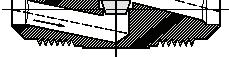
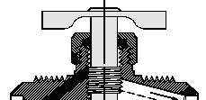
110
Page 109
Brass Products
Needle Valves

Compression Double
Inverted Straightway
“S” suffix designates Selfalign with nuts and sleeves.
“S” suffix designates Selfalign with nuts and sleeves.
designates
“B” prefix designates less inverted nut.
For replacement nut use 105x4. See page 37.

111 Tube Catalog O.D Number L M M1 3/16 A6763 1.06 0.88 1.03 1/4 A6765 1.13 0.88 1.03 1/4 A6765S 1.13 0.88 1.03 5/16 A6770 1.13 0.88 1.03 3/8 A6775 1.50 1.13 1.31
Tube Male Pipe Catalog O.D Thread Number L M M1 N 1/4 1/8 A735 1.41 0.84 1.01 0.72 1/4 1/8 B735 1.41 0.84 1.01 0.72
Tube Male Pipe Catalog O.D Thread Number L M M1 3/16 1/8 A6690 1.16 0.88 1.03 3/16 1/8 A6690S 1.16 0.88 1.03 1/4 1/8 A690 1.19 0.88 1.03 1/4 1/8 A690S 1.19 0.88 1.03 5/16 1/8 A660 1.18 0.90 1.05 5/16 1/4 A6755 1.28 0.91 1.09 5/16 1/4 A6755S 1.28 0.91 1.09 3/8 1/4 A6760 1.82 1.31 1.46 3/8 1/4 A6760S 1.82 1.31 1.46
Compression Straightway Tube Male Pipe Catalog O.D. Thread Number L M M1 N 3/16 1/8 A6845 1.50 0.82 1.07 0.50 1/4 1/8 A555 1.53 0.83 1.05 0.61 1/4 1/8 A555S 1.53 0.83 1.05 0.53 5/16 1/8 A655 1.56 0.84 1.09 0.52 5/16 1/4 A6855 1.73 0.92 1.28 0.69 5/16 1/4 A6855S 1.73 0.92 1.28 0.69 3/8 1/4 A6860 1.64 0.83 1.28 0.78 3/8 1/4 A6860S 1.64 0.83 1.28 0.78
Compression
“S” suffix
Selfalign with nuts and sleeves.
Angle
Page 110
Brass Products
Needle Valves
Male Pipe Double
Male to Female Pipe
Female Pipe
112 Male Pipe Catalog Thread Number L M M1 1/8 6810 1.38 0.66 0.80 1/4 6815 1.71 1.08 1.23 Fem. Male Pipe Pipe Catalog Thread Thread Number L M M1 1/8 1/8 6820 1.87 0.88 1.03 1/4 1/4 6825 1.87 1.09 1.24 Fem. Pipe Catalog Thread Number L M M1 G 1/8 6800 1.14 0.88 1.03 0.50 1/4 6805 1.62 1.11 1.26 0.68
Page 111
Brass Products
Needle Valves
Temperature Range: -40°F to +150°F with plastic sleeve.
For replacement Polyline nuts and sleeves, see page 59.
Temperature Range: -40°F to +150°F with plastic sleeve.
For replacement Polyline nuts and sleeves, see page 59.
113 Male Tube Pipe Catalog O.D Thread Number L M M1 1/4 1/8 530 1.31 0.88 1.03 1/4 1/4 6700 1.38 0.88 1.09 5/16 1/8 630 1.38 0.95 1.13 5/16 1/4 695 1.44 0.87 1.02 3/8 1/4 700 2.04 1.00 1.15
SAE 45° Flare Straightway
Male Tube Pipe Catalog O.D. Thread Number L M M1 N 1/4 1/8 320 1.54 0.86 1.07 0.74 5/16 1/8 325 1.59 0.94 1.22 0.88 5/16 1/4 6703 1.94 1.00 1.31 0.90 3/8 1/4 330 1.84 0.90 1.21 0.96
Male Tube Pipe Catalog O.D Thread Number L M M1 1/4 1/8 A690P 1.19 0.86 1.01 3/8 1/4 A6760P 1.50 1.18 1.33
Male Tube Pipe Catalog O.D. Thread Number L M M1 N 1/4 1/8 A555P 1.50 0.82 1.04 0.69 1/4 1/4 A556P 1.70 0.84 1.06 0.56 3/8 1/4 A6860P 1.85 0.99 1.44 0.88
SAE 45° Flare Angle
Polyline Straightway
Polyline Angle
Page 112
Brass Products
Drain Cocks
Drain Cocks and Drain Valves have been a specialty since 1919. Millions are in use. The original design has proved so efficient that it is still the leader with most original equipment manufacturers. The metal-to-metal seat requires only hand tightening to assure positive leak-proof performance.
Note: For additional technical questions, contact Technical Support at 1-888-258-0222.
Refer to safety information regarding proper selection of tubing and tube connectors on page 5.


Internal Seat (Long)

Typical Application: Brass bodies/steel handles, except where noted.
Pressure: 150 psi maximum (does not include hose or plastic tubing.)
Used With: Copper, aluminum, steel, hose and plastic tubing where applicable.
Temperature: -65°F to +250°F (-53°C to +121°C). (Refer to tubing temperature range.)
Conformance: Designed for automotive or industrial use. Not intended for natural gas, LPG, nuclear or aircraft applications, except as noted.
114
Male Pipe Catalog Thread Number C L L1 1/4 6788 9/16 1.56 0.44 External Seat Male Pipe Catalog Thread Number C L 1/8 185 7/16 1.72 Male Pipe Catalog Thread Number C L 1/8 135 7/16 0.90 1/4 145 9/16 1.00 3/8 270 11/16 1.25 1/2 108 7/8 1.52 External Seat Male Pipe Catalog Thread Number C L L1 1/8 130 17/32 1.15 1.30 1/4 140 5/8 1.32 1.50 1/4 190 9/16 1.25 1.41 3/8 230 11/16 1.34 1.50 Internal Seat
Page 113
Brass Products Drain Cocks


115 Male Pipe Catalog Thread Number C L M 1/8 6783 13/32 1.63 .344 Male Pipe Catalog Thread Number C L 1/8 1424A 1/2 1.219 1/4 1425A 9/16 1.313 3/8 1426A 11/16 1.688 Male Pipe Catalog Thread Number C L L1 1/8 705 13/32 0.78 0.88 Set screw has 10-32 national fine thread. Male Pipe Catalog Square Thread Number C L M M1 N 1/8 150 7/16 1.12 0.57 0.95 0.38 1/4 120 5/8 1.76 0.94 1.50 0.66 Male Hose Pipe Catalog Square I.D. Thread Number C L M M1 N 3/8 1/4 6660 9/16 1.33 0.62 1.01 0.66 Internal Seat Internal Seat Drain Valve Air Vent Angle Bib Drain Angle Bib Drain
Page 114
Brass Products Drain Cocks


116 Male Hose Pipe Catalog Size Thread Number C L M M1 N 5/8 3/8 211273A 11/16 2.85 1.41 1.91 1.30 Male Hose Pipe Catalog Square I.D. Thread Number C L M M1 N 5/8 3/8 211280A 11/16 2.85 1.10 1.47 1.19 Male Hose Pipe Catalog Square Size Thread Number C L M M1 N 3/8 3/8 1422 3/4 2.93 1.78 2.25 1.12 5/8 3/8 1423 13/16 2.93 1.81 2.25 1.35 3/4 3/8 1433 15/16 3.00 1.81 2.25 1.35 3/4 1/2 1451 15/16 3.12 1.93 2.25 1.35 Male Hose Pipe Catalog Size Thread Number L M M1 N 1/4 1/8 6600 3.36 0.80 0.97 0.84 Male Pipe Cable Catalog Thread Length Number 1/4 7" 1421-7 1/4 18" 1421-18 1/4 24" 1421-24 1/4 32" 1421-32 1/4 60" 1421-60 1/4 60" 1421-60A*
loop on cable end.
to Pipe (Steel Body) Pipe to Hose Shut-Off (Brass Body) Gasoline Shut-Off with Screen Filter Air Tank Drain Valve Red color coded aluminum handle. Handle Catalog Number 1427. Pull cable
Hose to Pipe (Steel Body)
*No
Hose
sideways.
Page 115
Brass Products
Trucks Valves
Typical Application: Used extensively in the trucking industry for cooling and fuel line applications.
Material: Forged brass bodies, steel handles.
Pressure Range: 200 psi maximum.
Temperature: -40°F to +250°F (-40°C to +121°C)
Conformance: Designed for trucking use. Not intended for natural gas, LPG, nuclear or aircraft applications.
Note: Buna-N o-ring sealed;
117 Hose Pipe Catalog I.D. Thread Number 5/8 1/2 7502 Truck Valve Hose Pipe Catalog I.D. Thread Number 5/8 3/8 7504 Truck Valve Hose Pipe Catalog I.D. Thread Number 3/8 3/8 7506 Truck Valve Female Male Pipe Pipe Catalog Thread Thread Number 1/2 1/2 7508 Truck
Female Male Pipe Pipe Catalog Thread Thread Number 3/8 3/8 7509
Valve
Truck Valve
Page 116
Brass Products
Plastic Drain Cocks
Material: Nylon 6 Fiber Reinforced.
Pressure Range: Up to 25 psi.
Used With Automotive Radiators:
Temperature: -50°F to +180°F (-46°C to +82°C)
Conformance: Designed for automotive use. Not intended for natural gas, LPG, nuclear or aircraft applications.
118 Chrysler M12x1.5 GM Ford and Mazda Ford (Long) M14x2.0 Ford (Short) Chrysler M12x1.25 Ford M14x1.25 Chrysler M10x1.25 Chrysler M14x1.25 GM M10x1.25 GM
Thread Catalog Number Captive 110 Thread Catalog Number Oversized 111 Thread Catalog Number Captive 112 Thread Catalog Number Captive 113 Thread Catalog Number M12x1.25 114 Thread Catalog Number M14x1.25 115 Thread Catalog Number M10x1.25 116 Thread Catalog Number M14x1.25 117 Thread Catalog Number M10x1.25 118 Thread Catalog Number M12x1.5 119 Thread Catalog Number M10x1.25 121 Thread Catalog Number M14x2.0 122 Thread Catalog Number 5/8–18 123 Thread Catalog Number M14x2.0 124 Thread Catalog Number 5/8–18 125 Thread Catalog Number 5/8–18 126 Thread Catalog Number Captive 127 Thread Catalog Number 1/2–18 128
Page 117
Brass Products
Ground Plug & Multiple Shut-Offs
Pressure Range: 30 psi working pressure, except where noted.
Used With: Copper, aluminum, steel and plastic tubing where applicable.
Material: Brass bodies and handles.
Temperature: -65°F to +250°F (-53°C to +121°C) with metal tubing. For use with plastic tubing, refer to the tubing temperature range.
Note: For additional technical questions, contact Technical Support at 1-888-258-0222.
Refer to safety information regarding proper selection of tubing and tube connectors on page 5.
Conformance: Designed for automotive or industrial use. Not intended for natural gas, LPG, nuclear or aircraft applications, except as noted.
Ordering Information: Order valve body, nut and sleeves by catalog number. Order valves with Selfalign nuts and sleeves by adding suffix “S”. Example: A694S. Order valves less nut and sleeve by adding prefix “B”. Example: B694.
Note:
Ground Plug Drains and Shut-Offs use a universal lubricant satisfactory for use with most common fluids. However the lubricant may wash out at higher pressures or with some exotic fluids.
119
Male Pipe Catalog Thread Number D L 1/4 W15310 .188 1.56 Draincock Male Pipe Catalog Thd. Number C L N M M1 1/8 6891 9/16 1.93 0.75 1.63 0.87 1/4 6892 5/8 1.62 0.75 1.75 1.03 3/8 6893 11/16 1.72 1.00 2.31 1.22 Ground Plug Drain Tube Catalog O.D. Number L M 1/4 6719 1.88 1.88 5/16 6724 1.88 1.88 3/8 6729 2.00 1.88 SAE 45° Flare Double D L M M1 L N C L M Ratings: Valves are designed to hold air pressure of 125 psi with one 1/4" bubble in 5 seconds permissible key leakage.
Page 118
Brass Products
Ground Plug & Multiple Shut-Offs
SAE 45° Flare Straightway
Compression Double Compression Straightway
Male to Female Pipe
Truck Shut Off Male to Female Pipe
Ratings: Valves are designed to hold air pressure of 125 psi with one 1/4" bubble in 5 seconds permissible key leakage.
120 Male Tube Pipe Catalog O.D. Thread Number L M 1/4 1/8 537 2.00 1.88 5/16 1/8 632 2.03 1.88 3/8 1/4 703 2.06 1.88 Tube Catalog O.D. Number L M 1/4 A6769 2.12 1.88 1/4 A6769S 2.12 1.88 5/16 A6774 2.19 1.88 3/8 A6779 2.25 1.88 3/8 A6779S 2.25 1.88 “S” suffix designates Selfalign with Nuts and Sleeves. Male Tube Pipe Catalog O.D Thread Number L M 1/4 1/8 A694 2.19 1.88 1/4 1/8 A694S 2.19 1.88 1/4 1/4 A6754 2.19 1.88 1/4 1/4 A6754S 2.19 1.88 5/16 1/8 A664 2.19 1.88 5/16 1/4 A6759 2.25 1.88 3/8 1/4 A6764 2.38 1.88 3/8 1/4 A6764S 2.38 1.88 “S” suffix designates Selfalign with Nuts and Sleeves. Male Female Pipe Pipe Catalog Thread Thread Number L M 1/8 1/8 6824 2.00 1.88 1/4 1/4 6829 2.12 1.88 Male Female Pipe Pipe Catalog Thread Thread Number C C1 L D 1/4 1/4 W20332 5/8 3/4 1.81 .218
L M L M L M L M D L C C1
Page 119
Brass Products
Ground Plug & Multiple Shut-Offs
Replacement Handle: Catalog Number 6746. Includes Screw.
Click-washer assembly positively holds valve in desired position and gives a pronounced click.
4 Way Multiple Shut-Off
Replacement Handle: Catalog Number 6746. Includes Screw.
Click-washer assembly positively holds valve in desired position and gives a pronounced click.
121 Female Pipe L Catalog Thread Stem Number 1/4 1.37 6747 1/4 2.37 6748 3/8 1.37 6707 3/8 2.37 6708
Male Female Pipe Pipe Catalog Thd. Thd. Number L M 1/4 1/4 6828 2.22 1.97 Marine Shut Off Male to Female Pipe UL Listed for Marine Fuel. U L L M 90° 90° Handle L Female Pipe Catalog Thread Number L M 1/8 6804 1.46 1.88 1/4 6809 1.70 1.88 Female Pipe Double L M Female Pipe L Catalog Thread Stem Number 1/4 1.37 6749 3/8 1.37 6709
Way Multiple Shut-Off 90° Handle L
3
Page 120
Brass Products
Brass Ball Valves
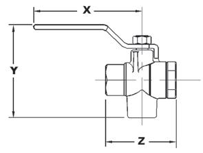
Forged Body Brass 3-Way Ball Valve
Features/Benefits
• Forged brass body
• Blowout proof stem
• Chrome plated ball
• Double o-ring stem seal - never needs tightening
• Floating ball design
• Standard steel handle
Applications
• Vacuum service
• Industrial service
• Machine/engine coolant
• Center off position
• Diverter valve
Service
• Working pressure: 500 psig bottom inlet@ 70ºF; 100 psig side inlets
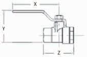
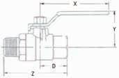
• Temperature range: -40ºF + 300ºF
• Orifice diameters: 1/4” = .440”, 3/8” = .500”, 1/2” = .500”
• Vacuum rating: Full
• For: Water, oils and gases
Note: Not steam rated.
Forged Body Brass Ball Valve
Features/Benefits
• Forged brass body
• Blowout proof stem
• Chrome plated brass ball
• Double o-ring stem seal
• Tamper proof design
• Floating ball design
• Standard steel handle
• 1/4 turn - full on/off
Applications
• Vacuum service
• Industrial service
• Machine/engine coolant
• Water service
• Fuel tank - gasoline/ diesel
Service
• Working pressure: 600 psig WOG @ 70ºF
• Temperature range: -40ºF + 300ºF
• Orifice diameters: 1/4”=.44”, 3/8”=.50”, 1/2”=.50”, 3/4”=.69, 1”=.88, 1-1/4”= 1.18, 1-1/2”=1.57, 2”= 1.89
• Vacuum rating: Full
• For: Water, oils and gases
Note: Not steam rated.
122 Part No. Connections Size X Y Z FF90587-04 F x F x F NPT 1/4” 3.20 3.12 2.25 FF90587-06 F x F x F NPT 3/8” 3.20 3.12 2.25 FF90587-08 F x F x F NPT 1/2” 3.20 3.12 2.25 X Y Z
Part No. Connections Size X Y Z FF90589-04 F x F x F NPT 1/4” 3.70 2.38 2.25 FF90589-06 F x F x F NPT 3/8” 3.70 2.38 2.25 FF90589-08 F x F x F NPT 1/2” 3.70 2.38 2.25 FF90589-12 F x F x F NPT 3/4” 3.80 2.72 2.98 FF90589-16 F x F x F NPT 1” 4.50 3.00 3.34 FF90589-20 F x F x F NPT 1-1/4” 6.20 3.78 3.65 FF90589-24 F x F x F NPT 1-1/2” 6.20 4.15 4.00 FF90589-32 F x F x F NPT 2” 6.20 4.75 4.76
Part No. Connections Size X Y Z D FF90588-04 M x F NPT 1/4” 3.70 2.38 2.75 1.13 FF90588-06 M x F NPT 3/8” 3.70 2.38 2.75 1.13 FF90588-08 M x F NPT 1/2” 3.70 2.38 2.75 1.13 FF90588-12 M x F NPT 3/4” 3.80 2.72 3.40 1.43 FF90588-16 M x F NPT 1” 4.50 3.00 4.00 1.71 FF90588-20 M x F NPT 1-1/4” 6.22 3.01 4.05 1.83 FF90588-24 M x F NPT 1-1/2” 6.22 3.24 4.35 2.01 FF90588-32 M x F NPT 2” 6.22 3.52 5.13 2.38
Page 121
Brass Products
Brass Ball Valves
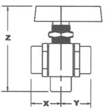
Features/Benefits
• Brass bar stock body
• Blowout proof stem
• Nickel plated ball
• Viton stem seal
• Double o-ring stem seal
- never needs tightening
• Metal retainer seal
• Center off position
• Seals: Ball seats = teflon, stem seals = 2 o-rings (Viton & Buna-n)
Applications
• Vacuum service
• Industrial service
• Center off position
• Water service
• Panel mounting
Services
• Working pressure: 1/8” & 1/4”=1500 psig @ 70oF 3/8” & 1/2”= 1,000 psig @ 70ºF (side port inlet) 1000 psig (bottom port inlet)
• Temperature range: -40ºF + 300ºF
• Orifice diameters: 1/8” & 1/4”=.250” 3/8” & 1/2”=.340”
• Vacuum rating: Full
• For: Water, oils and gases
• Panel mount hole size: 9/16” ID
Note: Not steam rated.
123 Part No. Connections Size X Y Z FF90597-02 F x F NPT 1/8” 0.92 0.92 2.12 FF90597-04 F x F NPT 1/4” 0.92 0.92 2.12 FF90597-06 F x F NPT 3/8” 1.10 1.10 2.59 FF90597-08 F x F NPT 1/2” 1.19 1.19 2.59 FF90598-02 Compression 1/8” 0.92 0.92 2.12 FF90598-04 Compression 1/4” 0.92 0.92 2.12 FF90598-06 Compression 3/8” 1.10 1.10 2.59 FF90598-08 Compression 1/2” 1.19 1.19 2.59
Brass Instrumentation 3-Way Ball Valve
Z XY
Page 122
Brass Products
Brass Ball Valves
Brass Instrumentation 2-Way 90 Degree Ball Valve
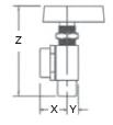
Features/Benefits
• Brass bar stock body
• Blowout proof stem
• Nickel plated brass ball
• Double o-ring stem seal
• Metal retainer seal
• 90º configuration eliminates fittings
• Seals: Ball seats = teflon, stem seals = 2 o-rings (Viton & Buna-n)
Applications
• Vacuum service
• Industrial service
• Water service
• Panel mount
Service
• Working pressure: 1/8” & 1/4”=1500 psig @ 70ºF 3/8” & 1/2”= 1,000 psig @ 70ºF (side port inlet) 1000 psig (bottom port inlet)
• Temperature range: -40ºF + 300ºF
• Orifice diameters: 1/8” & 1/4”=.250” 3/8” & 1/2”=.340”
• Vacuum rating: Full
• For: Water, oils and gases
• Panel mount hole size: 9/16” ID
Note: Not steam rated.
124
Part No. Connections Size X Y Z FF90595-02 F x F NPT 1/8” 0.92 0.38 2.12 FF90595-04 F x F NPT 1/4” 0.92 0.38 2.12 FF90595-06 F x F NPT 3/8” 1.10 0.75 2.59 FF90595-08 F x F NPT 1/2” 1.19 0.75 2.59 FF90596-02 Compression 1/8” 0.92 0.38 2.12 FF90596-04 Compression 1/4” 0.92 0.38 2.12 FF90596-06 Compression 3/8” 1.10 0.75 2.59 FF90596-08 Compression 1/2” 1.19 0.75 2.59
Page 123
Brass Products
Brass Ball Valves
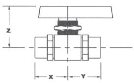
Features/Benefits
• Brass bar stock body
• Blowout proof stem
• Nickel plated ball
• Viton stem seal
• Standard metal handle
• Floating ball design
• 1/4 turn - full on/off
Applications
• Vacuum service
• Industrial service
• Coolant service
• Water service
• Compact shut off installations
• Low cost instrumentation
• Hose shut off
Service
• Working pressure: 1,000 psig WOG @ 70ºF
• Temperature range: -40ºF + 300ºF
• Orifice diameters: 1/8” & 1/4”=.250”
• Vacuum rating: Full
• For: Water, oils and gases
Note: Not steam rated.
Features/Benefits
• Brass bar stock body
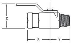
• Blowout proof stem
• Nickel plated ball
• Viton stem seal
• Metal retainer seal
• Seals: Ball seats = teflon, stem seals = 2 o-rings (Viton & Buna-n)
Applications
• Vacuum service
• Industrial service
• Water service
• Panel mounting Service
• Working pressure: 1/8” & 1/4”=1500 psig @ 70ºF 3/8” & 1/2”=1000 psig @ 70ºF
Service (cont)
• Temperature range: -40ºF + 300ºF
• Orifice diameters: 1/8” & 1/4”=.250” 3/8” & 1/2”=.375”
• Vacuum rating: Full
• For: Water, oils and gases
• Panel mount hole size: 9/16” ID
Note: Not steam rated.
125 Z X Y Brass Mini-Instrumentation 2-Way 90 Ball Valve Part No. Connections Size X Y Z FF90590-02 M x F NPT 1/8” 1.13 0.75 1.25 FF90590-04 M x F NPT 1/4” 1.13 0.81 1.25 FF90591-02 M x M NPT 1/8” 1.13 0.75 1.25 FF90591-04 M x M NPT 1/4” 1.13 0.81 1.25 FF90592-02 F x F NPT 1/8” 1.13 0.75 1.25 FF90592-04 F x F NPT 1/4” 1.13 0.85 1.25
Z XY Brass Instrumentation 2-Way Ball Valve Part No. Connections Size X Y Z FF90593-02 F x F NPT 1/8” 0.92 0.92 1.25 FF90593-04 F x F NPT 1/4” 0.92 0.92 1.25 FF90593-06 F x F NPT 3/8” 1.10 1.10 1.42 FF90593-08 F x F NPT 1/2” 1.19 1.90 1.42 FF90594-02 Compression 1/8” 0.92 0.92 1.25 FF90594-04 Compression 1/4” 0.92 0.92 1.25 FF90594-06 Compression 3/8” 1.10 1.10 1.42 FF90594-08 Compression 1/2” 1.46 1.46 1.42
Page 124
Brass Products Special Adapters
Refer to safety information regarding proper selection of tubing and tube connectors on page 5.
126 Male Male Straight Pipe Catalog Thread Thread Number C D L 1 AC-811 3/4 1408 1-3/8 .719 3.25 30° Flare Tube Turbocharger Discharge Connector Hose Catalog I.D. Number M M1 N 1/4 1410 0.88 1.00 1.02 Wiper Tee Tube Inverted Catalog O.D Nut Number C L 5/16 5/16 1428 1/2 4.50 3/8 3/8 1429 5/8 4.50 Transmission Oil Coolant Line Adapter SAE 45° Male Tube Pipe Catalog Size Thread Number C D L 3/8 1/4 1432 5/8 .282 1.90 Truck Oil Line Extended SAE 45° Flare Fitting (Replaces Roto Master No. 10-35) L D C M N M1 M1 L C L D C
Page 125
Brass Products Special Adapters
Ford Transmission Elbow Includes
Power Steering Male 37° JIC Adapter
Note: Other orifice sizes available (special order only).
Refer to safety information regarding proper selection of tubing and tube connectors on page 5.
127 Straight Tube Male Pipe Catalog O.D. Thread Number M N 5/16–28 1/8–27 1437 .94 .47
Tube Thread Thread Catalog O.D A B Number C D L 1/4 7/16–20 9/16–18 1440 9/16 .172 1.42 3/8 9/16–18 5/8–18 1439 5/8 .266 1.49
(Brass)Includes O-Rings. Inverted Tube Thread Thread Catalog O.D A B Number C D L 3/8 5/8–18 M14x1.5 1445 3/4 .266 1.18 3/8 5/8–18 M16x1.5 1446 3/4 .266 1.18 3/8 5/8–18 M18x1.5 1447 3/4 .266 1.18
Includes O-Rings. Inverted Male Catalog Thread A O-Ring B Number C D L 5/8–18 11/16–18 1444 3/4 .266 1.38
Includes O-Rings. Male Female Pipe Pipe Catalog Thread Thread Number C D L 1/8 1/8* 1512 1/2 .0625 0.75 * PTF short thread. Restriction Pipe Adapter (With .0625 Orifice) M N A B L D C A B L D C A B L D C
O-Rings.
Metric Power Steering Adapter
Ford Power Steering Fitting
Page 126
Brass Products
Special Adapters
Refer to safety information regarding proper selection of tubing and tube connectors on page 5.
128 Tube Thread Male Pipe Catalog O.D. Size Thread Number C D L 1/4 1/2–20 1/8 1513 9/16 .219 1.06 Carburetor to Fuel Line Adapter (Ford) For use with 59x4 L D C Male Inverted Pipe Catalog Male Thread Number D L 1/2-20 1/8 1514 1/2 .219 0.90 Fuel Line Adapter S.A.E. 45° Tube Tube Catalog O.D Size Number D L 1/4 1/4 1521 7/16 .188 1.09 AC Type Adapter SAE 45° Tube Inverted Catalog Size Male Number D L 1/4 3/16 1518 7/16 .189 1.03 1/4 1/4 1522 7/16 .189 1.03 3/8 5/16 1553 5/8 .234 1.34 3/8 3/8 1563 5/8 .282 1.38 3/8 7/16 1554 11/16 .282 1.40 Adapter SAE 45° Flare to Inv. Flare L D C
C C C Page 127
Brass Products Special Adapters
Special Steel Bushing
Male JIC 37° Flare to Metric O-Ring Port Adapter Steel (with o-ring)
Application: GM power steering with Saginaw steering and rack and pinion steering systems. Includes O-Ring.
Ford Nut
For use with 1513 (Nut similar to 59x4 for 3/16" tube, use 6100x3)
Transmission Coolant Line Adapters
AC8111 (Steel) Connector
Application:
PTT Thread 30° tube to male pipe adapter for diesel engines.
Refer to safety information regarding proper selection of tubing and tube connectors on page 5.
129 Female Male Pipe Catalog Thread Thread Number C D L 1-1/16-16UN-2A 1/8 7977 1-1/8 .328 .94 1-1/16-16UN-2A 3/8 7978 1-1/8 .562 .94
Tube Thread Catalog O.D B Number C D L 3/8 M14x1.5 M41157x6x14 3/4 .266 1.62 3/8 M16x1.5 M41157x6x16 3/4 .266 1.62 3/8 M18x1.5 M41157x6x18 3/4 .266 1.62
Inv. Inv. Catalog Female Male Number C D L 3/8 5/16 7915 3/4 .250 1.00 (5/8-18) (1/2-20) 5/16 3/8 7916 5/8 .220 0.94 (1/2-20) (5/8-18)
Tube Male Catalog Size Pipe Number C D L 1 (1-5/16–14) 1 C9200 1-3/8 .844 2.04 1 (1-5/16–14) 3/4 C9240 1-3/8 .800 1.84
(GMC)
L D C Tube Thread Catalog Size Size Number C D L 1/4 1/2-20 59x4 1/2 .258 0.64
L D C
L D C Page 128
Brass Products
Hydraulic Brake Products
Adapters can be used to adapt standard steel brake lines to the different size ports used in dual master cylinders. The tube O.D. is the outside diameter of
Refer to safety information regarding proper selection of tubing and tube connectors on page 5.
the steel brake line. Thread size can be determined by measuring with a U.S. or Metric screw pitch gauge. See pages 14 to 18.
130
Standard Invented Flare Tube And Thread Size Tube Size 1/8 3/16 1/4 5/16 3/8 7/16 1/2 5/8 3/4 7/8 1 Thread Size 5/16–28 3/8–24 7/16–24 1/2–20 5/8–18 11/16–18 3/4–18 7/8–18 1-1/16–16 1-3/16–16 1-5/16–16 9/16 - 20 Port 7910 Adapter Standard 3/16" Steel Line Standard Tube Nut (Steel) Tube Size Catalog Number 1/8 105x2 3/16 105x3 1/4 105x4 5/16 105x5 3/8 105x6 3/8 105x6x7* 7/16 105x7 1/2 105x8 5/8 105x10 3/4 105x12 7/8 105x14 1 105x16 *11/16–18 Thread Long Tube Nut (Steel) Tube Thread Catalog O.D. Size Number 3/16 3/8–24 7896x3 1/4 7/16–24 7896x4
Master Cylinder Adapter Inverted Inverted Catalog Male Thread Female Thread number (Exceptions Noted) (Exceptions Noted) 3/16 (9/16–18) 3/16 7911 3/16 (9/16–18) 3/16 (1/2–20) 7913 3/16 (9/16–20) 3/16 7910 3/16 1/4 7828 1/4 3/16 7818 7/16–20 1/4 7732* 1/4 (9/16–18) 1/4 7908 1/4 5/16† 7917 5/16 3/16 7817* 5/16 3/16 7909 5/16 3/16 (9/16–18) 7912 5/16 1/4 7727* 5/16 1/4 7829 5/16 5/16 1074* 5/16 3/8 7915 3/8 NPTF 5/16 7771 3/8 5/16 7916 † Seat may be used for 3/16”, 1/4”, 5/16” Tube Connection with 1/2-20 Thread. *Seals On Hex Face (E) Bubble Flare Inverted Catalog Male Thread Female Thread number 3/16 3/16 1441 5/16 3/16 7897
Master Cylinder Adapter
Dual
Dual
Page 129
Brass Products
Hydraulic Brake Products
Towed Trailer Brake Tee
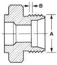
Metric Hydraulic Brake Products
How to Measure Metric
Metric threads are measured and specified by the thread diameter in millimeters and the pitch in millimeters per thread. If dimension “A” is
22mm and dimension “B” (crest to crest distance) is 1.5mm, then the metric thread size is M22 x 1.5.
*Use S Series Brake Lines. (standard flare)
**Use SJ Series Steel Brake Lines. (standard flare)
Adapter Standard to Metric Bubble
Used on Fiat applications when converting 3/16" (3/8–24) inverted flare brake lines to 3/16" (10x1.25) metric thread bubble flare.
131 Inverted Seat Male Thread Catalog A B C Number 3/16 (3/8–24) 3/16 (3/8–24) 3/16 inv. (3/8–24) 7900 3/16 (1/2–20) 3/16 (3/8–24) 1/2–20 inv. 7906 3/16 (9/16–18) 3/16 (3/8–24) 3/16 inv. (9/16–18) 7933 3/16 (9/16–20) 3/16 (3/8–24) 3/16 inv. (9/16–20) 7905 3/16 (7/16–24) 3/16 (3/8–24) 1/4 inv. (7/16–24) 7914 1/4 (7/16–24) 3/16 (3/8–24) 1/4 inv. (7/16–24) 7901 1/4 (9/16–18) 3/16 (3/8–24) 1/4 inv. (9/16–18) 7904 1/4 (7/16–24) 1/4 (7/16–24) 1/4 inv. (7/16–24) 7898
Female Std. Male Bubble Catalog Fl. Seat Fl. Tube Number 3/16" (3/8-24 thread) 3/16" (10x1.25 thread) 7970 Used on Fiat applications when converting 3/16" (3/8–24) inverted flare brake lines to 3/16" (10x1.25) metric thread bubble flare.
Standard to
Bubble Inverted Male Tube O.D./ Catalog Thread Female Thread Number M10 x 1.0 3/16 (3/8–24) 1443* Metric Adapter
Adapter
Metric
(standard flare)
*Use S Series Brake Lines.
Bubble Male Tube O.D./ Catalog Thread Female Thread Number M10 x 1.0 3/16 (3/8–24) 1442* M11 x 1.5 3/16 (M10 x 1.0) 7935** M12 x 1.0 3/16 (M10 x 1.0) 7936** M13 x 1.5 3/16 (M10 x 1.0) 7937**
**Use SJ Series Steel Brake Lines. (standard flare)
Metric Adapter
Inv.
Bolt Hole Catalog Number 1/4 19/32 7709 Brake Adapter Inv. Seat Bolt Hole Catalog Number 3/16 (3) 11/32 7812 1/4 (3) 11/32 7765*
Seat
strap
Inv. Bolt Hose End Catalog Seat Hole Port Number 3/16 (2) 9/32 3/8–24 7805 Rear
*Has flat
Strap Tee Assembly
Axle Tee
Threads B A
Female
Male
Catalog Fl. Seat Fl. Thread Number 3/16" (3/8-24 thread) 13x1.5 7972 3/16" (3/8-24 thread) 12x1.0 7974
inv.
metric Bubble
Page 130
Brass Products
Hydraulic Brake Products
Brake Line Unions for Domestic and Imported Vehicles
For joining Edelmann 6300 series metric thread
bubble flare 3/16" brake lines (10-1.0mm thread) (brass)
132 Description Catalog No. 3/16" line to 3/16" line (3/8–24 thread), (Standard Flare) ‘S’ Series 302x3 1/4" line to 1/4" (7/16–24 thread), (Standard Flare) ‘S’ Series 302x4 5/16" line to 5/16" line (1/2–20 thread), (Standard Flare) ‘S’ Series 302x5 3/8" line to 3/8" line
thread),
Flare) ‘S’ Series 302x6
7940
(5/8–18
(Standard
British line to British line (3/8–24 thread), (ISO flare) ‘SB’ Series (Steel)
European line to European line (10–1.0mm thread), (Bubble Flare) ‘SC’ Series (Steel) 7941 Japanese line to Japanese line (10–1.0mm thread), (Standard Flare) ‘SJ’ Series (Brass) 7934A
7975
Page 131
Plastic Products
Molded Compression Tube Products
Molded Compression Tube Products
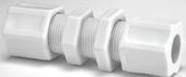
Sizes: Available in sizes 1/8" through 3/4" tube OD (7/8" tube OD and metric tube sizes available on request from Technical Support at 1-888-258-0222.
Materials:
Molded as standard in two materials: nylon and polypropylene
Nylon characteristics:
• good resistance to organic solvents, oils, and gasoline
• excellent impact resistance
• tolerant to repeated steam for wash down and longtime weathering
• F.D.A. and N.S.F. listed
• opaque
• 20% glass filled
• N.S.F. listed
• operating temperatures -30°F to 200°F (-34°C to 93°C) – not to exceed temperature specification of tubing
Available on request in two materials: Celcon®* (acetal copolymer) or KYNAR®** (polyvinylidene fluoride)
Styles: Available in two standard styles:
Ferrule Nut (integral nut and sleeve for soft tubing to 50 PSI )
Refer to safety information regarding proper selection of tubing and tube connectors on page 5.
Features and Benefits:
• leak-free performance
• high integrity in both mechanical and acoustical vibrations
• ten styles and over 400 part number configurations to meet your needs
• easy assembly – no special tools or tube preparation necessary
• reliability in side-loaded applications allows for compact plumbing
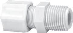
• For use with PT200, PT240, and TP160 plastic tubing
* Celcon is a registered trademark of Ticona.
** KYNAR is a registered trademark of Elf Atochem North America, Inc. Operating temperatures of Eaton connectors are regulated by ambient and fluid temperatures, type of fluid being carried, tubing type and conditions of mechanical abuse. Pressures in excess of above specifications in all connector sizes should be tested by the customer in the particular application.
Assembly Instructions
• operating temperatures -40°F to 200°F (-40°C to 93°C) – not to exceed temperature specification of tubing
Polypropylene characteristics:
• good chemical and corrosion resistance
• features ferrule and nut molded as a single part, eliminating the need for a two-piece assembly
Gripper Nut with separate plastic sleeve (for sure-grip with plastic tubing up to 220 PSI )
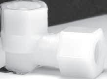
• for higher pressure applications
• connectors come fully assembled – for your convenience
• very low resistance to media flow resulting from material and internal surfaces
• no metal parts to corrode or present a safety hazard with aggressive chemicals
• ISO 9001 Certified
Maximum Operating Pressure:
Ferrule Nut series = 50 psi max
Gripper Nut series = 220 PSI max
Operating pressures of Eaton molded compression products are regulated by ambient and fluid tempera-
tures, type of fluid being carried, tubing type and conditions of mechanical abuse. Pressures in excess of above specifications in all fitting sizes should be tested by the customer for their particular application.
Used with: Plastic tubing: TP160, PT200,
and PT240.
Tube inserts are recommended for optimal performance with PT200 tubing.
Temperature Range:
Nylon = -40°F to +200°F (-40°C to +93°C)
Polypropylene = -30°F to +200°F (-34°C to +93°C)
133
Ferrule nut with integral sleeve low pressure application soft plastic tubing
*50 P.S.I. *220 P.S.I.
Tube
*50 P.S.I. *220 P.S.I.
Tube
*50 P.S.I. *220 P.S.I.
Ferrule nut with plastic gripper for use with plastic tubing for sure grip Tube Tube Stop
Ferrule Nut Fitting Body
Tube Stop
Ferrule Nut Fitting Body
Tube Stop
Ferrule Nut Fitting Body
Page 132
Plastic Products
Molded Compression Tube Products
Ranges are at maximum operating pressures (refer to tubing temperature range). The overlap of temperature ranges of the individual components will decide the actual temperature range of the assembly.
Assembly Instructions:
• Cut tubing to desired length; be sure the tube end is cut properly (maxi-
mum 10° cutting angle allowed).
• Insert the tubing through the back of the nut all the way through the nut assembly to the tube stop in the connector body (see illustration). If the tubing does not enter the nut easily, loosen the nut one turn and then insert the tubing all the way to the tube stop in the fitting body.
• Turn the nut to hand-tight.
• Tighten the nut an additional 2 to 2-1/2 turns past hand-tight or until the nut bottoms against the connector body, whichever comes first.
• All nuts must be retightened when the system reaches projected operating temperature.
Ordering Information
Molded compression connector are available in nylon and in polypropylene. They are also available by special order in KYNAR** (polyvinylidene fluoride) or Celcon* (acetal copolymer). To order fittings in KYNAR or Celcon, call Technical Support at 1-888-258-0222. Refer to Chemical Resistance Chart, pages 22-26. For detailed information on chemical compatibility, call Technical Support at1-888-258-0222. General material characteristics are as follows:
Nylon, F.D.A. and N.S.F. listed, has good resistance to organic solvents, oils and gasoline. Good strength at high temperatures. Cold and hot-water applications. Longtime weathering resistance. Good impact resistance, both single and repeated. Not recommended for use with bleach, acids, or chlorine.
Polypropylene, N.S.F. listed, has good chemical resistance. Withstands continuous temperatures up to 215°F (not to exceed
temperature specification of tubing). Unaffected by most weak acids, alkalies, alcohols and ketones. Do not use with oxidants or strong acids or in continuous sunlight. 20% glass filled for improved stiffness.
KYNAR, an F.D.A. and N.S.F. listed polyvinylidene fluoride, has outstanding chemical resistance for handling highly corrosive fluids.
Celcon, an acetal copolymer, N.S.F. listed and U.S.D.A. and F.D.A. listed for coffee, milk and antibiotics, has high tensile strength and good impact resistance over a broad temperature range. Translucent white color. Not affected by continuous hot-water service and works smoothly with metal tubing. Celcon cannot be recommended for continuous exposure to solutions with a chlorine concentration greater than 1 ppm. Suggested maximum continuous-use temperature is 220°F in air and 180°F in water (not to exceed temperature specification of
tubing). Unaffected by most inorganics, except sulfuric, nitric and hydrochloric acids. Should not be continuously exposed to sunlight.
Most connectors can be ordered with a GRIPPER style nut. Fittings with a GRIPPER style nut are capable of handling greater pressure than those with standard style nut.
For ordering connectors with ‘GRIPPER’ nut, add ‘G’ to the end of the part number (example: 1568x4x4G or 1568Px4x4G). Some connectors are NOT available with the GRIPPER style nut, while others are ONLY available with the GRIPPER style nut. For more information, call Technical Support at 1-888-258-0222.
Note:
It is not necessary to disassemble the connector for assembly. Merely insert tubing to stop and tighten compression nut.
134
* Celcon is a registered trademark of Ticona.
** KYNAR is a registered trademark of Elf Atochem North America, Inc.
Assembly Instructions Continued Page 133
Plastic Products
Molded Compression Tube Products
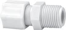
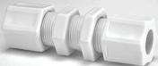
• Not available with GRIPPER style nut Sold ONLY with GRIPPER style nut
To order with ‘GRIPPER’ nut, add ‘G’ to the end of the part # (Except where noted!)
Example: 1568x4x4G or 1568Px4x4G
135 Male Connector Male Catalog Catalog Tube Pipe Number Number O.D Thread Nylon Polypropylene L D C 1/8 1/8 1568x2• 0.88 0.13 7/16 1/4 1/8 1568x4 1568Px4 0.99 0.26 5/8 1/4 1/8 1568x4G 1568Px4G 0.99 0.26 5/8 1/4 1/4 1568x4x4 1568Px4x4 1.17 0.26 5/8 1/4 1/4 1568x4x4G 1568Px4x4G 1.17 0.26 5/8 1/4 3/8 1568x4x6G 1568Px4x6 1.20 0.26 13/16 5/16 1/8 1568Px5 1.00 0.32 11/16 5/16 1/4 1568x5x4 1568Px5x4 1.19 0.32 11/16 3/8 1/8 1568x6x2 1568Px6x2 1.14 0.38 13/16 3/8 1/8 1568Px6x2G 1.14 0.38 13/16 3/8 1/4 1568x6 1568Px6 1.30 0.38 13/16 3/8 1/4 1568x6G 1568Px6G 1.30 0.38 13/16 3/8 3/8 1568x6x6 1568Px6x6 1.34 0.38 13/16 3/8 3/8 1568x6x6G 1.34 0.38 13/16 3/8 1/2 1568x6x8 1568Px6x8 1.59 0.38 59/64 3/8 1/2 1568x6x8G 1568Px6x8G 1.59 0.38 59/64 1/2 1/8 1568x8x2G 1.23 0.51 15/16 1/2 1/4 1568x8x4 1568Px8x4 1.42 0.51 15/16 1/2 1/4 1568Px8x4G 1.42 0.51 15/16 1/2 3/8 1568x8 1568Px8 1.47 0.51 15/16 1/2 3/8 1568x8G 1568Px8G 1.47 0.51 15/16 1/2 1/2 1568x8x8 1568Px8x8 1.61 0.51 15/16 5/8 3/8 1568x10x6G 1.50 0.63 1-1/16 5/8 1/2 1568x10G 1568Px10G 1.66 0.63 1-1/16 3/4 3/4 1568x12x12G 1568Px12x12G 1.92 0.76 1-5/16 Tube 1/8 1/4 5/16 3/8 1/2 5/8 3/4 O.D. (125) (.250) (.312) (.375) (.500) (.625) (.750) Tube Thread Size 5/16–24 7/16–20 1/2–20 5/8–20 3/4–20 7/8–20 1-1/16–20 Bulkhead Union Catalog Catalog Tube Number Number O.D. Nylon Polypropylene L I D C 1/4 1574x4 1.45 0.88 0.26 5/8 3/8 1574x6 1574Px6 1.78 1.03 0.38 13/16 1/2 1574x8 1.89 1.04 0.51 15/16 3/4 1574x12G 1574Px12G 2.41 1.35 0.76 1-5/16 D I L C D L C Ferrule Nut Fitting Body
Page 134
Plastic Products
Molded Compression Tube Products

• Not available with GRIPPER style nut Sold ONLY with GRIPPER style nut
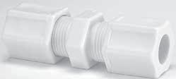
136 Female Connector Female Catalog Catalog Tube Pipe Number Number O.D. Thread Nylon Polypropylene L D C 1/4 1/8 1566x4 0.92 0.23 9/16 1/4 1/8 1566x4G 0.92 0.23 9/16 1/4 1/4 1566x4x4 1566Px4x4 1.09 0.22 11/16 1/4 1/4 1566x4x4G 1.09 0.22 11/16 5/16 1/4 1566x5x4 1.22 0.28 11/16 5/16 1/4 1566x5x4G 1.22 0.28 11/16 3/8 1/4 1566x6 1.20 0.36 11/16 3/8 3/8 1566x6x6 1566Px6x6 1.20 0.36 13/16 3/8 3/8 1566x6x6G 1.20 0.36 13/16 3/8 1/2 1566x6x8 1566Px6x8 1.27 0.34 1-3/64 3/8 1/2 1566x6x8G 1566Px6x8G 1.27 0.34 1-3/64 1/2 3/8 1566x8 1.23 0.47 13/16 1/2 3/8 1566x8G 1.23 0.47 13/16 1/2 1/2 1566x8x8 1566Px8x8 1.30 0.48 15/16 Union Connector Catalog Catalog Tube Number Number O.D. Nylon Polypropylene L F C 1/4 1562x4 1562Px4 0.98 0.23 5/8 1/4 1562x4G 1562Px4G 0.98 0.23 5/8 5/16 1562x5 1.03 0.28 11/16 5/16 1562x5G 1562Px5G 1.03 0.28 11/16 3/8 1562x6 1562Px6 1.23 0.30 13/16 3/8 1562x6G 1562Px6G 1.23 0.30 13/16 1/2 1562x8 1562Px8 1.44 0.48 15/16 1/2 1562Px8G 1.44 0.48 15/16 5/8 1562x10G 1562Px10G 1.50 0.50 1-1/16 3/4 1562x12G 1562Px12G 1.75 0.64 1-5/16 Catalog Catalog Tube Tube Number Number O.D. O.D. Nylon Polypropylene L D C D1 1/4 1/8 1562Px4x2• 0.92 0.26 5/8 0.13 5/16 1/4 1562x5x4• 1.00 0.32 11/16 0.26 3/8 1/4 1562x6x4G 1.19 0.38 13/16 0.26 1/2 3/8 1562Px8x6 1.33 0.51 15/16 0.38 5/8 1/2 1562Px10x8G 1.47 0.63 1-1/16 0.51 D L C A D1 L D F C
Page 135
Plastic Products
Molded Compression Tube Products
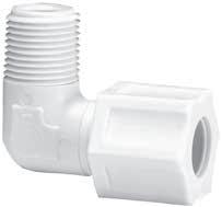
• Not available with GRIPPER style nut Sold ONLY with GRIPPER style nut
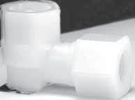
137 Male Elbow Male Catalog Catalog Tube Pipe Number number Across O.D.. Thd. Nylon Polypropylene M N D D1 Flats F 1/8 1/8 1569Px2• 0.56 0.63 0.11 0.20 1/4 1/4 1/8 1569x4 0.81 0.81 0.22 0.25 3/8 1/4 1/8 1569x4G 0.81 0.81 0.22 0.25 3/8 1/4 1/4 1569x4x4 1569Px4x4 0.81 1.02 0.22 0.28 3/8 1/4 1/4 1569x4x4G 1569Px4x4G 0.81 1.02 0.22 0.28 3/8 1/4 3/8 1569x4x6 0.84 1.09 0.23 0.38 9/16 3/8 1/4 1569x6 1569Px6 0.94 1.03 0.30 0.31 37/64 3/8 1/4 1569x6G 1569Px6G 0.94 1.03 0.30 0.31 37/64 3/8 3/8 1569x6x6 1569Px6x6 0.94 1.09 0.34 0.38 9/16 3/8 3/8 1569x6x6G 0.94 1.09 0.34 0.38 9/16 1/2 1/4 1569x8x4G 1.06 1.09 0.39 0.31 11/16 1/2 3/8 1569x8 1569Px8 1.09 1.13 0.39 0.31 11/16 1/2 3/8 1569x8G 1.09 1.13 0.39 0.31 11/16 1/2 1/2 1569x8x8 1569Px8x8 1.09 1.28 0.47 0.36 11/16 1/2 1/2 1569x8x8G 1569Px8x8G 1.09 1.28 0.47 0.36 11/16 5/8 1/2 1569x10G 1569Px10G 1.25 1.44 0.52 0.50 13/16 Female Elbow Female Catalog Catalog Tube Pipe Number Number Across O.D. Thread Nylon Polypropylene M N D C Flats F 1/4 1/8 N/A 0.81 .75 0.26 35/64 25/64 1/4 1/4 1570x4x4 0.81 .97 0.26 11/16 13/32 5/16 1/4 1570x5x4G 1570Px5x4G 0.94 1.00 0.32 11/16 7/16 3/8 3/8 1570x6x6 1570Px6x6 0.91 1.03 0.38 13/16 9/16 N D D M F M N D F C
Page 136
Plastic Products
Molded Compression Tube Products
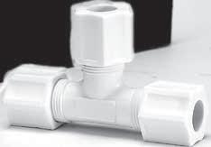
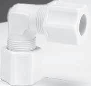
• Not available with GRIPPER style nut Sold ONLY with GRIPPER style nut
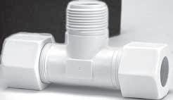
138 Union Tee Catalog Catalog Tube Number Number Across O.D. Nylon Polypropylene L D N Flats F 1/8 1564x2• 1.11 0.11 0.52 1/4 1/4 1564x4 1564Px4 1.44 0.22 0.72 23/64 1/4 1564x4G 1.44 0.22 0.72 23/64 5/16 1564x5G 1564Px5G 1.61 0.28 0.83 7/16 3/8 1564x6 1564Px6 1.91 0.30 0.97 17/32 3/8 1564Px6G 1.91 0.30 0.97 17/32 1/2 1564x8 1564Px8 2.13 0.48 1.03 11/16 1/2 1564x8G 2.13 0.48 1.03 11/16 5/8 1564x10G 2.56 0.50 1.25 13/16 3/4 1564x12G 3.11 0.62 1.56 1-1/16 Catalog Catalog Tube Number Number Across O.D. Nylon Polypropylene M D Flats F 1/4 1565x4 – 0.81 0.22 3/8 1/4 1565x4G – 0.81 0.22 3/8 3/8 1565x6 1565Px6 0.94 0.34 9/16 3/8 1565x6G 1565Px6G 0.94 0.34 9/16 1/2 1565x8 1565Px8 1.06 0.39 43/64 1/2 1565x8G – 1.06 0.39 43/64 5/8 1565x10G – 1.25 0.52 13/16 Union Elbow Male Branch Tee Male Catalog Tube Pipe Number Across 0.D. Thd. Nylon L D N D1 Flats F 1/4 1/8 1572x4 1.45 0.22 0.75 0.25 3/8 1/4 1/8 1572x4G 1.45 0.22 0.75 0.25 3/8 1/4 1/4 1572x4x4x4 1.45 0.22 0.92 0.31 3/8 1/4 1/4 1572x4x4x4G 1.45 0.22 0.92 0.31 3/8 5/16 1/4 1572Px5x5x4 1.61 0.30 0.98 0.31 27/64 3/8 3/8 1572x6x6x6 1.91 0.36 1.11 0.38 1/2 1/2 1/2 1572x8x8x8 2.19 0.48 1.31 0.48 5/8 D L N F D1 M D F M D L N F
Page 137
Plastic Products Molded Compression Tube Products
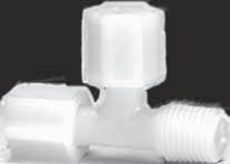

• Not available with GRIPPER style nut Sold ONLY with GRIPPER style nut
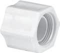
139 Male Catalog Catalog Tube Pipe Number Number Across O.D. Thd. Nylon Polypropylene L D N Flats F 1/4 1/8 1571x4 1.47 .22 .73 3/8 1/4 1/4 1571x4x4x4 1.67 .22 .72 23/64 1/4 1/4 1571x4x4x4G 1.67 .22 .72 23/64 5/16 1/4 1571x5x4x5G 1571Px5x4x5 1.81 .28 .81 7/16 3/8 3/8 1571x6x6x6 1571Px6x6x6 2.03 .34 .97 1/2 1/2 3/8 1571x8 2.27 .47 1.11 5/8 1/2 3/8 1571Px8G 2.27 .47 1.11 5/8 1/2 1/2 1571x8x8x8G 2.41 .47 1.11 39/64 3/4 1/2 N/A 1571Px12G 3.17 .64 1.55 1-1/16 Male Run Tee Catalog Tube Number O.D. Nylon C L D 1/4 1561x4 5/8 0.63 0.26 5/16 1561x5 11/16 0.69 0.32 3/8 1561x6 13/16 0.75 0.38 1/2 1561x8 15/16 0.88 0.51 Catalog Catalog Tube Number Number O.D. Nylon Polypropylene C L D 1/4 1561x4G 5/8 0.69 0.26 3/8 1561x6G 13/16 0.73 0.38 1/2 1561x8G 1561Px8G 15/16 0.88 0.51 Insert Catalog Tube Number O.D. Nylon E L D 1/4 1584x4 0.25 0.38 0.12 5/16 1584x5 0.31 0.40 0.14 3/8 1584x6 0.37 0.50 0.20 1/2 1584x8 0.49 0.56 0.30 Compression Nut E D L 1/16 Ferrule Nuts with Integral Sleeve L D D L With Plastic Gripper C D L N F
Page 138
Plastic Products
Molded Compression Tube Products
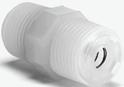

Ferrule Nuts with Integral Sleeve
Cap Nut
Bulkhead Nut
KYNAR Check Valve
KYNAR** Check Valve
Features and Benefits:
• Viton® “O” Ring
• Stainless Ball & Spring
• Zero Leakage
• Maximum Operating Temp.180°F @ 220 PSI
• Cracking Pressure 1 to 2.5
PSI
Viton is a registered trademark of DuPont Dow Elastomers
** KYNAR is a registered trademark of Elf Atochem North America, Inc.
140 Catalog Male Pipe Number Size N.P.T.F. KYNAR Only L J C 1/8 1531x2 1.00 0.09 7/16 1/4 1531x4 1.41 0.19 5/8 3/8 1531x6 1.50 0.25 13/16 1/2 1531x8 1.81 0.34 15/16
Catalog Catalog Tube Number Number O.D. Nylon Polypropylene L C 1/8 1529x2 0.52 7/16 1/4 1529x4 1529Px4 0.63 5/8 3/8 1529x6 0.73 13/16 1/2 1529x8 1529Px8 0.88 15/16 Catalog Catalog Tube Number Number O.D. Nylon Polypropylene C 1/4 1502x4 5/8 5/16 1502Px5 11/16 3/8 1502x6 13/16
L D D L
Gripper C L J Flow Diameter C Ferrule
Sleeve L D D L
Gripper C
With Plastic
Nuts with Integral
With Plastic
Page 139
Plastic Products
Temperature Range: -40°F to +350°F.
Material: Nylon 6/6
Not recommended for fuel line applications.
Refer to safety information regarding proper selection of tubing and tube connectors on page 5.
141 Tube Tube Catalog I.D. a I.D. b Number 1/8 1/8 1911 1/8 3/16 1923 1/8 1/4 1924 3/16 3/16 1912 1/4 3/16 1914 1/4 1/4 1913 1/4 3/8 1915 5/16 5/16 1925 3/8 3/8 1927
Straight Connector Tube Tube Tube Catalog i.d. A i.d. B i.d. C Number 1/8 1/8 1/8 1916 1/8 1/8 3/16 1917 1/8 1/8 1/4 1918 1/8 3/16 1/8 1939 3/16 1/8 3/16 1940 3/16 3/16 3/16 1902 3/16 3/16 1/8 1920 3/16 3/16 1/4 1921 1/4 3/16 3/16 1942 1/4 1/4 1/4 1903 1/4 1/4 3/16 1943 5/16 5/16 5/16 1906 3/8 3/16 3/8 1944 3/8 1/4 3/8 1945 3/8 3/8 3/16 1907 3/8 3/8 1/4 1908 3/8 3/8 3/8 1922 3 Way Tee Tube Tube Tube Catalog I.D. A I.D. B I.D. C Number 3/16 3/16 3/16 1932 1/4 1/4 1/4 1935 1/4 3/8 3/8 1936 5/16 5/16 5/16 1937 3/8 3/8 3/8 1938 Y Connector Tube I.D. Catalog All Ends Number 3/16 1948 4 Way Tee Tube I.D. Catalog All Ends Number 3/16 1949 5 Way Tee Tube I.D. Catalog Size Number 5/32–1/4–3/8 1901 Universal Connector Tube Tube Catalog i.d. A i.d. B Number 1/8 3/16 1928 3/16 3/16 1929 3/16 1/4 1930 1/4 1/4 1931 Elbow Connector Tube I.D. Catalog Size Number 5/32–1/4–3/8 1900 Universal Tee A B A B A C B A C B
Page 140
Brass-Nickel Plated BSPP Products
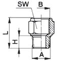
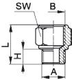

*M5 has 0.8mm Thread Pitch. M5 seals with nylon washer, included.

142 Female Male NPTF Catalog SW BSPP Thread Number H L (mm) 1/8 1/8 1150x2x2PP 0.27 0.67 14 1/4 1/4 1150x4x4PP 0.32 0.91 17 3/8 3/8 1150x6x6PP 0.35 0.96 22 1/2 1/2 1150x8x8PP 0.39 1.16 27
Male To NPTF Female Adapter BSPP Female To NPTF Male Adapter Female Male NPTF Catalog SW BSPP Thread Number H L (mm) M5* 10-32† 1100x5MMxA 0.18 0.47 8 1/8 1/8 1100x2PPx2 0.37 0.77 14 1/4 1/4 1100x4PPx4 0.51 1.06 17 3/8 3/8 1100x6PPx6 0.51 1.08 19
BSPP
†UNF
SW L H A SW L H A Refer to safety information on page 5.
thread
Page 141
Related Products Assembly & Tool Cutting Equipment
Caution: Sharp blade! Keep hands and fingers away from cutting surface!
Need to cut stainless steel tubing? This cutting tool is for you. It features an enclosed feed screw to eliminate clogging and jamming. Grooved rolls for close to flare cuts and a fold away reamer.
Capacity:
1/8" to 1-1/8" O.D. Cuts hard and soft copper, aluminum, brass, carbon steel and stainless steel tubing.
Spare Parts:
T-1422R Replacement Cutting Wheel
Air Brake Products & Measuring Kits
Reams both inside and outside edges of tube with three hollow ground tool steel cutters. Fluted body is shaped to fit comfortably in palm of hand.
Capacity:
3/16" to 1-1/2" O.D. Reams copper, brass, aluminum and other tubing.
Thread Measuring Kit
Weatherhead Part # TA-1002
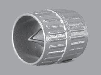
Aeroquip Part # FT1341
Measuring tube and pipe fitting threads can be a most difficult task if not completely understood. Tools needed include a thread pitch gauge, calipers and seat angle gauges. To aid you, Eaton has a kit to fit your needs.
This handy kit includes:
• Thread Pitch Gauge (American and metric)
• Inside/Outside Caliper (inches and millimeters)
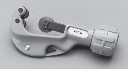
• 2 Seat Angle Gauges (37°/45° and a 12°/30° )
• International Measuring and Identification Guide and Instruction Booklet
• Carrying Case for Easy and Convenient Storage
143 143
T-150 Utility Tube Cutter
T-1430 Inner-Outer Reamer
How to Identify Fluid Ports and Connectors
Refer to safety information on page 5.
Page 142
Related Products
Tube Cutting Equipment
Weatherhead
Aeroquip

An economical alternative to quality tube and hose cutting. This versatile tool is lightweight and durable for long service life.
Replacement Blade: Weatherhead=T-135B Aeroquip=FT1356-2-1
Capacity: Up to 1" I.D.
Note: Not for use with wire-reinforced hose.
One hand operation for quick, clean cuts through plastic or nylon compound tubing and solid or fiber-reinforced hose up to 1" O.D.
• Any wireless hose or tubing.
• Power steering hose
• Air Conditioning hose
• Air brake hose
• Air system nylon tubing
• Thermoplastic hose
• Low pressure plastic tubing (PT200, PT230, PT240)
Replacement Blade: T-138B
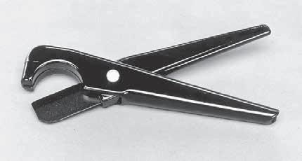
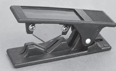
Note: Not for use with wire-reinforced hose.
A tool designed to be small, only 2-7/8" long. The versatile T-191 offers quick and clean square cuts on 1/16" to 1/2" O.D. plastic tubing and non-wire reinforced hose. The T-191 can be either bench or wall mounted and offers the safety of closing automatically when not in use.
Spare Parts: T-191B Replacement Blade (one per package)
144
Plastic Tube Cutter
Part # T-135
Part # FT1356
T-138 Hose and Tube Cutter
T-191 Plastic Tube and Hose Cutter
Refer to safety information on page 5. Page 143
Related Products Tube Bending Tools
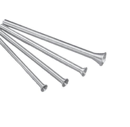
Spring Tube Benders
Low cost, tube bending spring operates perfectly in hand bending copper, aluminum and other thin-walled tubing. Bends are true with
minimum tubewall collapsing. Belled at one end to facilitate removal. Brightplated spring wire finish.
145 145
Catalog Tubing (O.D.) Length Number (Inches) (Inches) Weight T-104 1/4 10 4 ozs. T-105 5/16 10 4 ozs. T-106 3/8 10 5 ozs. T-107 7/16 12 7 ozs. T-108 1/2 12 8 ozs. T-1010 5/8 12 10 ozs. Catalogs Length Number Sets (Inches) Weight T-100 1/4, 3/8, 10 &12 1-1/2 lbs. 1/2, 5/8 T-200 1/4, 5/16, 10 & 12 1-1/4 lbs. 3/8, 1/2
to
information on page
Page 144
Refer
safety
5.
Equipment Tube Flaring & Brazing Tools
Tube flaring and cutting has just become a little easier with the convenient T-345K Tube Flaring and Cutting Kit. This kit features a qualitymade Double Flaring Tool offering accurate single flares between 3/16" and 5/8" O.D. tubing. Double flares between 3/16" and 1/2" O.D. tubing.
Check these features:
• Hardened, smooth cone for fast, accurate 45° flares.
• Single and double flare capability.
• Clamp screw for easy clamping and removal of tubes.
• Flaring Bar installed from either side of yoke.
• Flares soft copper, brass, aluminum and mild steel (JIC and Bundy) tubing.
Refer to safety information on page 5.
T-345K Components can be ordered separately:
T-345
45° Flaring Tool, Double Flare Adapters and Plastic Box
T-150
1/8" to 1-1/8" Tube Cutter
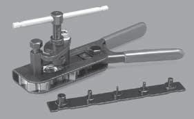
T-1422R
T-150 Spare Cutting Wheel
Economical, fast operating tool. Quick slip-on aluminum alloy yoke. Easy operating, swivel-type, hard chrome finished cone assures smooth flares.
Yoke slips down over top of bar and locks into position with a single turn.
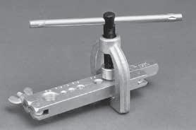
Flaring Capacity: 3/16", 1/4", 5/16", 3/8", 7/16", 1/2", and 5/8" O.D. Forms 45° flares in soft copper, aluminum and brass.
This new style tool makes single or double flaring easier and quicker than ever. Cam action provides positive, non-slip grip on the tubing with just a squeeze of the handle. Double flaring bar also serves as gauge for correct tubing height to insure perfect flares.
Flaring Capacity: 3/16", 1/4", 5/16", 3/8", 1/2" and 5/8" O.D. for single flares, and up to 1/2" O.D. for double flares. Can be
used with copper, aluminum, brass, bundyweld and steel tubing.
Weight: 2 lbs.
T-220 Components can be ordered separately
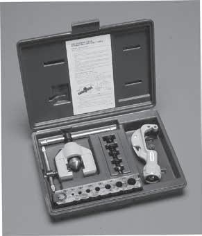
T-210 Tool for single flaring only
T-221 Double Flaring Bar only.
Flaring Capacity: 3/16", 1/4", 5/16", 3/8" and 1/2"
146
T-345K Tube Cutting and Flaring Kit
T-1022 Flaring Tool (45°)
T-220 Double Flaring Tool (45°)
Catalog Number Tube O.D. T-346x3 3/16" T-346x4 1/4" T-346x5 5/16" T-346x6 3/8" T-346x8 1/2"
Double Flare Adapters
Page 145
Related Products Label Sets & Bags
Label Sets
Full assortment available. Each label contains catalog number, illustration, size data and color coding for quick, positive identification of parts. Labels slide easily into slots on drawers and
Catalog Number Description
CL-490 Standard brass products, drain and shut-off cocks.
CL-491 Air brake products for copper tubing.
CL-492 Hydraulic brake products.
CL-494 Master Set - contains one each of CL-490, CL-491, CL-492.
CL-496 Mini-Barb products.
CL-497 Air brake products for nylon tubing.
CL-498 Polyline products.
CL-499 Push>Connect
CL-500 Selfalign
CL-501 Plastic products
CL-503 QCAB products
Self-Adhesive
Label Sets
Labels are printed on selfadhesive stock for quick application. Each label contains an illustration of the part along with the catalog number and size information.
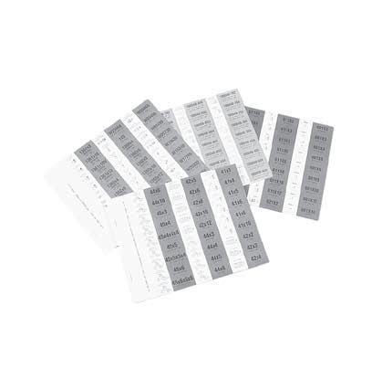
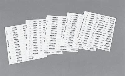
Catalog Number Description
FS-800 Air brake products for copper tubing
FS-900 Air brake products for nylon tubing
FS-1000 Mini-Barb products
FS-2100 Polyline products
FS-3300 QCAB products
W-8022 Standard brass products and drain-shut-off valve
Plastic Bags
Eaton heavy-duty plastic bags for brass products come in sizes 5"x6", 6"x10", and 8"x12". The bags include convenient spaces for labeling.
Catalog Number Description Qty
5x6 PB Plastic Bag 100
6x10 PB Plastic Bag 100
8x12 PB Plastic Bag 100
147 147
to safety information on page 5. Page 146
Refer
Related Products
Cabinets & Assortments
Stock Cabinet
Weatherhead Part # FC-16X
Aeroquip Part # FT1600
Contains 16 clear plastic drawers that can be divided into two or three sections. Illustrated color labels are available to provide instant identification of drawer contents.
Stock Cabinet
Weatherhead Part # C-15X
Aeroquip Part # FT1601
Contains 15 extra large white drawers for those large, difficult to store items. The 15 drawers may be divided into two or three sections to suit your particular needs.
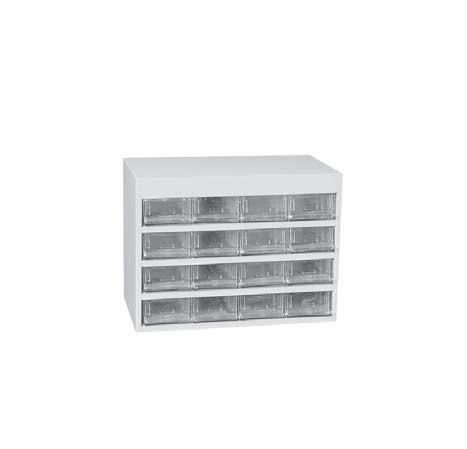
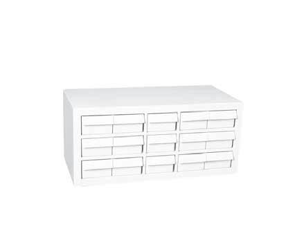

Size: 16-1/8" wide x 11-3/4" high x 9" deep
Weight: 13 lbs.
Size: 30-1/4" Wide x 14-3/8" Deep x 13-5/8" High
Weight: 45 lbs.
CD-15 FT1605 Individual Drawers

Stock Cabinet
Weatherhead Part # C-63X
Aeroquip Part # FT1602
A cabinet containing 63 drawers that can be divided into two or three sections. The bright color and attractive design make the stock cabinet a nice addition to any store front.
Size: 30-1/4" wide x 25" high x 9-1/4" deep
Weight: 61 lbs.
Weatherhead
2: C-63X, 1: C-15X, 1: CB-63X
Aeroquip Part #
2: FT1602, 1: FT1601, 1: CB-63X
This Brass Products Cabinet is a space saving, efficient, easy to use addition to the modern store with lobby type sales area. The cabinet requires a minimum of space but does a maximum job merchandising the wide variety of products in the 126 clear, wide, plastic drawers. An additional 15 large, high impact plastic drawers located in the bottom section provide ample space for those large or heavy special items you may be stocking.
Restocking is easy when you start at the bottom and pull drawers for an order check. Leave drawers extended that are low in stock. Now start at top, note quantity needed and return drawers to original position after order is written using
C-15X
standard box quantities listed on labels. Plastic dividers are provided to section drawers for future expansion when new or additional part numbers are needed.
Display this attractive cabinet with a recommended stock in your lobby and watch your brass product sales increase as the cabinet silently and quickly services your customers. Create those impulse sales that make your business and profits grow!
Size: 68-1/2" high, 30" wide, 15" deep.
Weight: 167 lbs.
CD-15D FT1606 Dividers Weatherhead
148
Cabinet
Part #
Weatherhead Aeroquip Part # Part # Description
Aeroquip Part # Part # Description
FT1601 15 Drawer Cabinet
FT1602 63 Drawer Cabinet
CB-63X Cabinet Base
FT1605 Plastic Drawer for C-15X/FT1601
C-63X
CB-63X
CD-15
Page 147
Related Products Assortments
The CA-632 assortment combines a lobby display unit and an assortment of fast moving brass products with coverage for most any application. This space saving assortment includes color coded, illustrated, labels for quick identification by customers of stan-
Contents only: CA-632CO & C-632X Brass Cabinet Only ( 2 C-63x, 1C-15x, 1CB-63x)
dard products, as well as fuel line, carburetion, metric and domestic hydraulic brake and thermoplastic brass fittings in 240 configurations and sizes. Be a supplier to auto dealers, brake specialists, RV shops, plant maintenance shops, truck and bus fleets, contractors,
marinas, loggers, shipyards, fishing fleets, farmers and self installers for their brass requirements. Contents of this assortment may vary as new products are introduced and stock changes in popularity.
149 149
CA-632 Brass Products Assortment and Cabinet
05703B-102 5 05704B-102 10 05704B-104 5 05704B-C02 5 05705B-102 10 05705B-104 5 05705B-C02 10 05705B-C04 10 05705B-1560 10 05705B-1561 10 05706B-102 10 05706B-104 10 05706B-106 5 05706B-C02 5 05706B-C04 5 05706B-1568 5 05706B-1570 5 100x3 10 100x4 10 100x5 10 100x6 10 105x2 10 105x3 20 105x4 20 105x5 20 105x6 10 131x3 10 131x4 10 131x5 10 131x6 10 135 10 140 5 1442 5 1443 5 145 10 1514 5 1538 10 1548 10 1539 10 1540 10 202x3 10 202x4 10 202x4x4 10 202x5 10 202x5x4 10 202x6 10 202x6x2 5 2030x4 10 2030x44 10 2030x5 10 2030x6 10 2030x8 5 252x3 10 252x4 10 270 5 302x3 10 302x4 10 302x5 10 302x6 5 3129x2 5 3150x2 10 3150x4 10 3151x2 10 3151x4 10 3151x6 10 3151x8 5 3152x2 10 3152x4 10 3152x6 10 3152x8 5 3152x12 2 3200x2 10 3200x4 5 3200x4x2 10 3200x6x4 5 3200x8x6 5 3220x4x2 20 3220x6x2 10 3220x6x4 10 3220x8x2 5 3220x8x4 10 3220x8x6 5 3220x12x6 2 3220x12x8 2 3300x2 10 3300x4 10 3300x4x2 10 3300x6 5 3300x6x4 5 3300x8 5 3300x8x6 5 3325x2 10 3325x4 10 3325x4x2 5 3325x6 5 3325x6x4 5 3326x2 10 3326x4 10 3326x6 10 3326x8 5 3327x2 10 3327x4 5 3328x2 10 3328x4 5 3328x6 5 3350x2 5 3350x4 5 3350x6 5 3400x2 10 3400x4 10 3400x6 5 3400x8 5 3500x2 10 3500x4 10 3600x2 5 3600x4 5 3700x2 10 3700x4 5 3700x6 5 3750x2 5 3750x4 5 402x3 10 402x4 10 402x4x4 5 402x5 10 402x5x4 10 402x6 10 41x3 10 41x4 10 41x5 10 41x6 10 41x8 5 42x4 5 42x6 5 48x3 10 48x4 10 48x4x4 10 48x5 10 48x5x4 10 48x6 10 48x6x2 5 48x6x6 5 48x8 5 49x4 10 49x4x4 5 49x5 10 49x5x4 5 49x6 10 49x8 5 60x2 50 60x3 50 60x4 50 60x5 50 60x6 50 60x8 20 60x10 10 61x2 10 61x3 20 61x4 20 61x5 20 61x6 10 61x8 10 6100x2 10 6100x3 10 6100x4 10 62x2 10 62x3 10 62x4 10 62x5 10 62x6 10 62x8 5 62x10 1 6200x2 10 6200x3 10 6200x4 10 6205-004 10 64x4 5 64x6 5 66x2 10 66x3 10 66x4 10 66x6 5 6660 5 6749 1 68x2 10 68x3 10 68x4 10 68x4x4 10 68x5 10 68x5x4 10 68x6 10 68x6x2 10 68x6x6 5 68x8 5 6809 5 6829 5 6892 5 69x2 10 69x3 10 69x4 10 69x4x4 10 69x5 10 69x5x4 10 69x6 10 69x6x2 5 69x6x6 5 69x8 5 7818 5 7828 5 7829 5 7896x3 5 7896x4 5 7904 5 7906 5 7908 2 7914 2 7934A 5 7935 5 7936 5 7937 5 7940 5 7941 5 C - 632x 1 C6 - 490 1 Catalog Number Qty. Catalog Number Qty. Catalog Number Qty. Catalog Number Qty. Catalog Number Qty. Catalog Number Qty.
Page 148
Related Products Assortments
This assortment of draincocks, shutoffs, and air brake fittings for use with 1/4", 3/8", and 1/2" copper tubing is a must for jobbers and fleet service shops. Provides excellent coverage for air brake tube and hose service requirements. The large plastic drawers and the illustrated labels for the 15 drawer cabinet included in the assortment make positive part selection simple and quick.
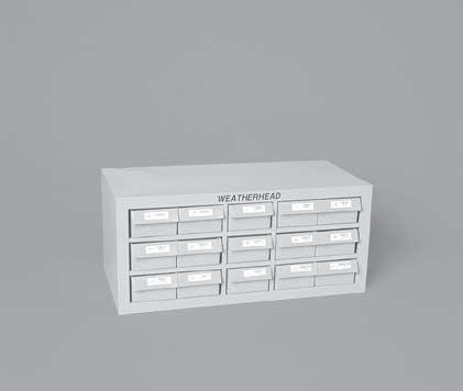
150
Part Number Qty 1360x6 20 1360x8 20 1360x10 10 1360x12 10 1361x6 20 1361x8 5 1361x10 5 1362x4 5 1362x6 10 1362x8 5 1362x10 5 1368x6 10 1368x6x2 5 1368x6x6 5 1368x8 5 1368x10 5 1369x4x4 5 1369x6 10 1369x8 5 1380x6 5 1390x6 5 1391x6 5 145 10 Part Number Qty 33806-A 20 33806-B 5 33806B-Y06 2 33806B-Y24 5 33806B-Y28 5 33806B-Y34 5 33806B-Y38 5 6707 1 6708 1 6709 1 6747 1 6748 1 6749 1 FH-15X 1 FS-800 1 W05465 5 W14630 10 W15310 5 W76150 5 W79850 3 W79851 3
AB-45 • Air Brake Fittings Assortment
Page 149
Related Products Assortments

The AB-1400 contains DOT approved brass air brake fittings for servicing nylon brake and secondary air lines. Selecting the proper fittings from the 63-drawer cabinet included with the assortment is easy. Clear, wide plastic drawers with color-coded labels make identification of shapes and sizes quick and simple. Order Eaton air brake tubing to complete your nylon air brake line service center.
This assortment of 1/4", 3/8", and 1/2" air brake fittings designed for use with Eaton air brake tubing provides the coverage needed for service work by fleets, repair shops, and farm implement dealers. The DOT-approved air brake fittings are easily selected from the cabinet with 16 plastic drawers and colorcoded labels included in the assortment.
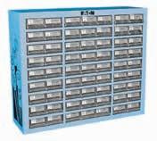
151 151
Part Number Qty 1460x4 20 1460x6 20 1460x8 20 1461x4 10 1461x6 10 1461x8 5 1462x4 5 1462x6 10 1462x8 4 1468x4 10 1468x6 10 1468x8 5 1469x4 5 1469x6 5 Part Number Qty 1469x8 5 1484x4 20 1484x6 20 1484x8 20 145 10 CL-16-3 1 FC-16X 1 W15310 5
AB-140 • 1400 Series Air Brake Fittings Assortment
Part Number Qty. 1460x4 10 1460x6 20 1460x8 10 1460x10 10 1460x12 10 1461x4 5 1461x6 10 1461x8 5 1461x10 5 1461x12 5 1462x4 5 1462x6 10 1462x8 5 1462x10 4 1462x12 2 1464x6 5 1464x8 5 1466x6 5 1466x6x6 5 1466x8 5 1468x4 5 1468x4x4 5 1468x6 10 1468x6x2 5 1468x8 5 1468x10 5 1468x12 4 1469x4 5 Part Number Qty. 1469x4x4 5 1469x6 10 1469x6L 5 1469x6x2 5 1469x6x6 5 1469x8 5 1469x8x4 5 1469x10 5 1469x10x6 4 1469x12 4 1471x4 5 1471x6 5 1472x6 5 1472x8 5 1480x6 5 1480x6x6 5 1480x8 5 1480x10 4 1484x4 20 1484x6 20 1484x8 20 1484x10 10 1484x12 10 C-63X 1 CL-497 1
AB-1400 • Air Brake Fittings Assortment
Page 150
Related Products Assortments
Ideal for fleet repair shops, truck dealers, garages and truck stops. SA-1 contains an assortment of popular 1/8" and 1/4" brass fittings plus 200' of Eaton air brake tubing. The 1/8" fittings are Eaton SELFALIGN® and 1/4" fittings are Eaton 1400 series air brake. The sturdy box keeps the tubing and fittings together for quick and easy servicing of the tubing used on shifters, PTO’s, wipers, horns, remote air, instrumentation, etc. All of the parts are organized at your finger tips. The SA-1 is a must for all vehicle air system maintenance facilities.
Size
15" wide, 3-1/2" high, 14-1/2" deep.
The SA-2 assortment enables you to supply fleets and dealers with fittings and tubing for 1/4" and 3/8" O.D. air brake applications. 1/8" O.D. tubing and fittings are also supplied for applications such as transmission shifter, air horn, gauge and flat adjustment. A cabinet is also supplied for easy storage on shelves and bench tops.
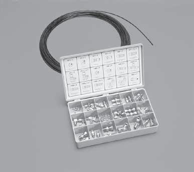
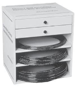
152
Part Number Qty. 1460x4 10 1461x4 5 1462x4 2 1464x4 1 1468x4 2 1468x4x1 2 1468x4x4 2 1469x4 2 1469x4x4 2 1484x4 5 601x2 10 Part Number Qty. 611x2 5 621x2 2 661x2 2 681x2 2 681x2x1 2 691x2 2 691x2x1 2 BF-40X 1 4245-0220-0100 100' 4249-0410-0100 100' Part Number Qty. 1460x4 10 1460x6 20 1461x4 5 1461x6 10 1462x4 5 1462x6 10 1464x4 2 1464x6 2 1466x6 5 1468x4 5 1468x4x4 5 1468x4x6 2 1468x6 10 1472x4 5 1472x6 5 1472x6x6x6 5 1484x4 10 1484x6 10 1485x4 10 1485x6 10 Part Number Qty. 1468x6x2 5 1468x6x6 5 1468x6x8 5 1469x4 5 1469x4x4 5 1469x6 10 1469x6x6 5 601x2 10 611x2 10 621x2 5 661x2 5 681x2 5 681x2x1 2 691x2 5 691x2x1 2 BL-456-X 1 FS-SA-2 1 3270-0110-0100 100' 4245-0220-0100 100' 4247-0410-0100 100' SA-1 • Secondary Air Systems Kit SA-2 • Secondary Air Systems Kit
Page 151
Related Products Assortments

Designed as a glove box sized emergency repair kit, the QC-18 assortment contains QCAB tube unions in 5/32", 1/4", 3/8", and 1/2" sizes, also included is a T-191 tubing cutter. The contents are contained in a convenient carrying case measuring 1-1/4" x 3-3/4" x 7".
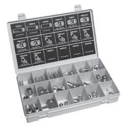

The QC-180 contains tube unions, male connectors, swivel male 45° elbow, male 90° elbows, and repair kits in popular 1/4", 3/8", and 1/2" tube sizes designed for DOT Truck and Trailer Air Brake System needs (see complete listing at right in table). The QCAB fittings are field proven with over millions of miles of leak free performance. Their design can save up to 75 percent of the assembly time over conventional compression fittings. These fittings are contained in a case measuring 1-3/4" x 6-3/4" x
This assortment contains a solid inventory of popular Eaton QCAB fittings designed for DOT Truck and Trailer Air Brake System needs (see complete listing at right in table). The QCAB fittings are field proven with over millions of of leak free performance. Their design can save up to 75 percent of the assembly time over conventional compression fittings.
153 153
1-3/4". Component Part No. Qty. 1862x2.5 2 1862x6 2 1862x8 2 T-191 1 QC-18X 1 QC18L 1 Component Part No. Qty. 1862x4 2 1869x8x8 1 1862x6 2 1880x4x4 2 1862x8 2 1880x6x6 2 1868x2.5 2 1880x8x8 1 1868x3 2 1800Kx4 2 1868x4x4 2 1800Kx6 2 Component Part No. Qty. 1868x6x6 2 1800Kx8 2 1868x8x8 2 1800TRK 1 1869x4x4 2 BF-40X 1
QC-18 QC-180
Component Part No. Qty. 1800Kx2.5 4 1862x10 2 1868x12 2 1874x6x6 1 1800Kx3 4 1868x2.5x1 5 1869x4 5 1874x8x8 1 1800Kx4 4 1868x2.5 5 1869x4x4 5 1880x4x4 5 1800Kx6 4 1868x3 5 1869x6 5 1880x6x6 5 1800Kx8 4 1868x4 5 1869x8 5 1880x8x8 5 1800Kx10 2 1868x4x4 5 1869x8x8 5 1880x10 2 Component Part No. Qty. 1800Kx12 2 1868x6 5 1869x10 2 1880x12 2 1862x2.5 2 1868x6x6 5 1869x4S 5 1800T 1 1868x8 5 1869x4x4S 5 CL-503 1 1862x4 5 1868x8x8 5 1869x6S 5 FC-16X 1 1862x6 5 1868x10x6 2 1869x8S 5 T-191 1 1862x8 5 1868x10 2 1874x4x4 1 QC-1800
Page 152
Related Products Assortments
Brass Products Assortment
Weatherhead Part # CA-631
Aeroquip Part # FT1607
This merchandiser will help you nize your brass products in an attractive 63 drawer cabinet. It includes a stock of the 100 est moving brass products to better service your customers. To expand, divide the clear, easy to inventory, super sized plastic drawers in half or thirds with plastic dividers provided.
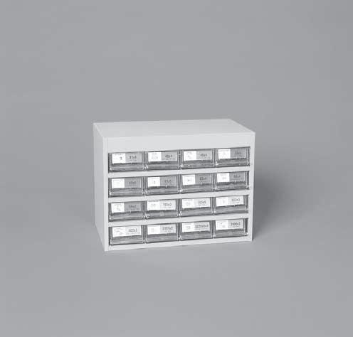
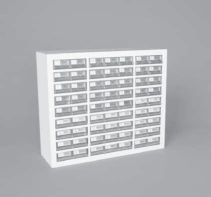
Illustrated, color-coded labels in a wide range of connector types provide instant identification of drawer contents. Your lobby and sales will be improved with this modern display set up on a gondola or shelf. Contents may vary as new numbers become available and popularity changes.
Weatherhead Part # FC-161 Aeroquip Part # FT1608
The brass products assortment contains the fastest moving SAE 45° Flare, Inverted Flare, Compression and Pipe catalog numbers to give your customers maximum coverage at a low cost. Nuts, sleeves and unions make an ideal stock for any
small repair, auto, boat, lawn mower, or fixit shop. Cabinet includes 16 clear plastic drawers and color-coded labels for easy identification. The cabinet fits on any shelf and goes to work immediately.
154
Catalog Number Qty. Catalog Number Qty. Catalog Number Qty. Catalog Number Qty. Catalog Number Qty. Catalog Number Qty. CA-631 Contents 105x3 20 105x4 20 105x5 20 105x6 10 131x3 10 131x4 10 131x5 10 131x6 10 135 10 145 10 202x3 10 202x4 10 202x4x4 10 202x5 10 202x5x4 10 202x6 5 302x3 10 302x4 10 302x5 10 302x6 5 402x4 10 402x5 10 402x6 10 3150x2 5 3150x4 5 3151x2 10 3151x4 10 3151x6 10 3151x8 10 3200x4x2 10 3200x6x4 5 3220x4x2 20 3220x6x2 10 3220x6x4 10 3220x8x2 5 3220x8x4 10 3220x8x6 5 3300x2 10 3300x4 10 3300x4x2 10 3300x6 5 3326x6 10 3327x2 5 3327x4 5 3328x2 5 3328x4 5 3350x2 5 3350x4 5 3400x2 10 3400x4 10 3400x6 5 3700x2 10 3700x4 5 3750x4 5 3750x6 2 41x4 10 41x6 10 48x4 10 48x4x4 10 48x5 10 48x5x4 10 48x6 10 48x6x6 5 49x4 5 49x6 10 60x2 50 60x3 50 60x4 50 60x5 50 60x6 50 61x2 10 61x3 10 61x4 10 61x5 10 61x6 10 62x2 10 62x3 10 62x4 10 62x5 10 62x6 10 68x2 10 68x3 10 68x4 10 68x4x4 10 68x5 10 68x5x4 10 68x6 10 68x6x2 10 69x4 10 69x6 10 C-63X or FT1602 1 CL-490 1
Brass Products Assortment
105x3 10 105x4 10 105x5 10 105x6 5 145 5 202x4 2 202x5 2 302x3 5 302x4 5 302x5 2 3151x2 2 3151x4 2 3220x4x2 5 3220x6x4 5 3300x2 5 3300x4 2 3400x2 5 3400x4 5 402x3 2 402x4 2 402x5 2 41x4 2 41x5 2 41x6 2 48x4 2 48x5 2 48x6 2 49x4 2 49x5 2 49x6 2 60x3 20 60x4 20 60x5 20 60x6 20 61x3 10 61x4 10 61x5 10 61x6 5 62x3 5 62x4 5 62x5 5 62x6 5 68x4 2 68x5 2 68x6 2 69x4 2 69x5 2 69x6 2 CL-16-1 1 FC-16X or 1 FT1600 Catalog Number Qty Qty Catalog Number Qty Catalog Number Qty FC-161 Contents
Page 153
Related Products Assortments
Weatherhead Part # PC-48 Aeroquip Part # FT1613
Eaton PUSH > CONNECT products are designed for quick assembly without the need for a wrench. Ideal for pneumatic applications where space is tight. Then product is also easily disconnected; simply depress the collet ring with two fingers
and withdraw the tube. The PC-48 and FT1613 provides the 48 most popular PUSH > CONNECT products in a compact, handy plastic box to make your assortment organized and accessible.
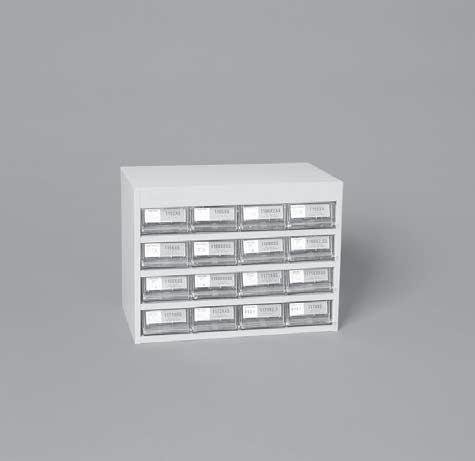
155 155
Push>Connect Products Assortment
Catalog Number Qty. Catalog Number Qty. Catalog Number Qty. Catalog Number Qty. Catalog Number Qty. Catalog Number Qty. PC-48 Contents 1162x2 5 1162x4 5 1162x6 5 1164x2.5 5 1164x4 5 1164x6 5 1164x8 2 1165x2.5 5 1165x4 5 1165x6 5 1165x8 2 1166x4 5 1166x4x4 5 1166x6 5 1166x6x6 2 1168x2 2 1168x2.5 5 1168x2.5A 5 1168x2.5x4 5 1168x2x4 5 1168x4 5 1168x4A 5 1168x4x4 5 1168x4x6 5 1168x5 5 1168x5x4 5 1168x6 5 1168x6x6 5 1168x6x8 2 1168x8 5 1168x8x8 2 1169x2.5S 5 1169x2S 5 1169x2x4S 5 1169x4S 5 1169x4x4S 5 1169x4x6S 5 1169x6S 5 1169x6x6S 5 1169x8S 2 1169x8x4S 2 1171x4S 5 1171x4x4S 5 1171x6S 5 1172x4S 5 1172x4x4S 5 1174x2 5 1174x4 5 CL-499 1 FC-16X or FT1600 1
Page 154
156 Registrar Product Facility Registration Number Responsibility Cleveland, TN ISO9002 SGSUS98/1495 Distribution of Eaton Product
Certification ISO & QS Certifications Page 155
Eaton Hydraulics - Brass Products
Conversion Conversion Chart
157 Inches Fractions Decimals MM – .0004 0.0100 – .0040 0.1000 – .0100 0.2500 1/64 .0156 0.3970 – .0197 0.5000 – .0295 0.7500 1/32 .0313 0.7940 – .0394 1.0000 3/64 .0469 1.1910 – .0590 1.5000 1/16 .0620 1.5880 5/64 .0781 1.9840 – .0787 2.0000 3/32 .0940 2.3810 – .0984 2.5000 7/64 .1090 2.7780 – .1181 3.0000 1/8 .1250 3.1750 – .1378 3.5000 9/64 .1410 3.5720 5/32 .1560 3.9690 – .1575 4.0000 11/64 .1720 4.3660 – .1770 4.5000 3/16 .1875 4.7630 – .1969 5.0000 13/64 .2030 5.1590 – .2165 5.5000 7/32 .2190 5.5560 15/64 .2340 5.9530 – .2362 6.0000 1/4 .2500 6.3500 – .2559 6.5000 17/64 .2656 6.7470 – .2756 7.0000 9/32 .2810 7.1440 – .2953 7.5000 19/64 .2970 7.5410 5/16 .3120 7.9380 Inches Fractions Decimals MM – .3150 8.0000 21/64 .3280 8.3340 – .3350 8.5000 11/32 .3440 8.7310 – .3543 9.0000 23/64 .3590 9.1280 – .3740 9.5000 3/8 .3750 9.5250 25/64 .3910 9.9220 – .3937 10.0000 13/32 .4060 10.3190 – .4130 10.5000 27/64 .4220 10.7160 – .4331 11.0000 7/16 .4380 11.1130 29/64 .4530 11.5090 15/32 .4690 11.9060 – .4724 12.0000 31/64 .4840 12.3030 – .4920 12.5000 1/2 .5000 12.7000 – .5118 13.0000 33/64 .5156 13.0970 17/32 .5310 13.4940 35/64 .5470 13.8910 – .5512 14.0000 9/16 .5630 14.2880 – .5710 14.5000 37/64 .5790 14.6840 – .5906 15.0000 19/32 .5940 15.0810 39/64 .6090 15.4780 5/8 .6250 15.8750 – .6299 16.0000 41/64 .6406 16.2720 – .6496 16.5000 21/32 .6560 16.6690 – .6693 17.0000 43/64 .6720 17.0660 Inches Fractions Decimals MM 11/16 0.6875 17.4630 45/64 0.7030 17.8590 – 0.7087 18.0000 23/32 0.7190 18.2560 – 0.7283 18.5000 47/64 0.7340 18.6530 – 0.7480 19.0000 3/4 0.7500 19.0500 49/64 0.7656 19.4470 25/32 0.7810 19.8440 – 0.7874 20.0000 51/64 0.7970 20.2410 13/16 0.8125 20.6380 – 0.8268 21.0000 53/64 0.8280 21.0340 27/32 0.8440 21.4310 55/64 0.8590 21.8280 – 0.8662 22.0000 7/8 0.8750 22.2250 57/64 0.8906 22.6220 – 0.9055 23.0000 29/32 0.9062 23.0190 59/64 0.9220 23.4160 15/16 0.9375 23.8130 – 0.9449 24.0000 61/64 0.9530 24.2090 31/32 0.9690 24.6060 – 0.9843 25.0000 63/64 0.9844 25.0030 1 1.0000 25.4000 – 1.0236 26.0000 1-1/32 1.0312 26.1940 1-1/16 1.0620 26.9880 – 1.0630 27.0000 1-3/32 1.0940 27.7810 – 1.1024 28.0000 1-1/8 1.1250 28.5750 – 1.1417 29.0000 1-5/32 1.1560 29.3690 Inches Fractions Decimals MM – 1.1811 30.0000 1-3/16 1.1875 30.1630 1-7/32 1.2190 30.9560 – 1.2205 31.0000 1-1/4 1.2500 31.7500 – 1.2598 32.0000 1-9/32 1.2810 32.5440 – 1.2992 33.0000 1-5/16 1.3120 33.3380 – 1.3386 34.0000 1-11/32 1.3440 34.1310 1-3/8 1.3750 34.9250 – 1.3779 35.0000 1-13/32 1.4060 35.7190 – 1.4173 36.0000 1-7/16 1.4380 36.5130 – 1.4567 37.0000 1-15/32 1.4690 37.3060 – 1.4961 38.0000 1-1/2 1.5000 38.1000 1-17/32 1.5310 38.8940 – 1.5354 39.0000 1-9/16 1.5620 39.6880 – 1.5748 40.0000 1-19/32 1.5940 40.4810 – 1.6142 41.0000 1-5/8 1.6250 41.2750 – 1.6535 42.0000 1-31/32 1.6562 42.0690 1-11/16 1.6875 42.8630 – 1.6929 43.0000 1-23/32 1.7190 43.6560 – 1.7323 44.0000 1-3/4 1.7500 44.4500 – 1.7717 45.0000 1-25/32 1.7810 45.2440 – 1.8110 46.0000 1-13/16 1.8125 46.0380 1-27/32 1.8440 46.8310
Page 156
158 Inches Fractions Decimals MM – 1.8504 47.0000 1-7/8 1.8750 47.6250 – 1.8898 48.0000 1-29/32 1.9062 48.4190 – 1.9291 49.0000 1-15/16 1.9375 49.2130 – 1.9685 50.0000 1-31/32 1.9690 50.0060 2 2.0000 50.8000 – 2.0079 51.0000 2-1/32 2.0313 51.5940 – 2.0472 52.0000 2-1/16 2.0620 52.3880 – 2.0866 53.0000 2-3/32 20.9400 53.1810 2-1/8 2.1250 53.9750 – 2.1260 54.0000 2-5/32 2.1560 54.7690 – 2.1650 55.0000 2-3/16 2.1875 55.5630 – 2.2047 56.0000 2-7/32 2.2190 56.3560 – 2.2440 57.0000 2-1/4 2.2500 57.1500 2-9/32 2.2810 57.9440 – 2.2835 58.0000 2-5/16 2.3120 58.7380 – 2.3228 59.0000 2-11/32 2.3440 59.5310 – 2.3622 60.0000 2-3/8 2.3750 60.3250 – 2.4016 61.0000 2-13/32 2.4060 61.1190 2-7/16 2.4380 61.9130 – 2.4409 62.0000 2-15/32 2.4690 62.7060 – 2.4803 63.0000 Inches Fractions Decimals MM 2-1/2 2.5000 63.5000 – 2.5197 64.0000 2-17/32 2.5310 64.2940 – 2.5590 65.0000 2-9/16 2.5620 65.0880 2-19/32 2.5940 65.8810 – 2.5984 66.0000 2-5/8 2.6250 66.6750 – 2.6380 67.0000 2-21/32 2.6560 67.4690 – 2.6772 68.0000 2-11/16 2.6875 68.2630 – 2.7165 69.0000 2-23/32 2.7190 69.0560 2-3/4 2.7500 69.8500 – 2.7559 70.0000 2-25/32 2.7810 70.6439 – 2.7953 71.0000 2-13/16 2.8125 71.4376 – 2.8346 72.0000 2-27/32 2.8440 72.2314 – 2.8740 73.0000 2-7/8 2.8750 73.0250 2-29/32 2.9062 73.8190 – 2.9134 74.0000 2-15/16 2.9375 74.6130 – 2.9527 75.0000 2-31/32 2.9690 75.4060 – 2.9921 76.0000 3 3.0000 76.2000 3-1/32 3.0312 76.9940 – 3.0315 77.0000 3-1/16 3.0620 77.7880 – 3.0709 78.0000 3-3/32 3.0940 78.5810 – 3.1102 79.0000 3-1/8 3.1250 79.3750 Inches Fractions Decimals MM – 3.1496 80.0000 3-5/32 3.1560 80.1690 3-3/16 3.1875 80.9630 – 3.1890 81.0000 3-7/32 3.2190 81.7560 – 3.2283 82.0000 3-1/4 3.2500 82.5500 – 3.2677 83.0000 3-9/32 3.2810 83.3440 – 3.3071 84.0000 3-5/16 3.3120 84.1377 3-11/32 3.3440 84.9314 – 3.3464 85.0000 3-3/8 3.3750 85.7250 – 3.3858 86.0000 3-13/32 3.4060 86.5190 – 3.4252 87.0000 3-7/16 3.4380 87.3130 – 3.4646 88.0000 3-15/32 3.4690 88.1060 3-1/2 3.5000 88.9000 – 3.5039 89.0000 3-17/32 3.5310 89.6940 – 3.5433 90.0000 3-9/16 3.5620 90.4877 – 3.5827 91.0000 3-19/32 3.5940 91.2810 – 3.6220 92.0000 3-5/8 3.6250 92.0750 3-21/32 3.6560 92.8960 – 3.6614 93.0000 3-11/16 3.6875 93.6630 – 3.7008 94.0000 3-23/32 3.7190 94.4560 – 3.7401 95.0000 3-3/4 3.7500 92.2500 – 3.7795 96.0000 Inches Fractions Decimals MM 3-25/32 3.7810 96.0440 3-13/16 3.8125 96.8380 – 3.8189 97.0000 3-26/32 3.8440 97.6310 – 3.8583 98.0000 3-7/8 3.8750 98.4250 – 3.8976 99.0000 3-29/32 3.9062 99.2190 – 3.9370 100.0000 3-15/16 3.9375 100.0130 3-31/32 3.9690 100.8060 – 3.9764 101.0000 4 4.0000 101.6000 4-1/16 4.0620 103.1880 4-1/8 4.1250 104.7750 – 4.1338 105.0000 4-3/16 4.1875 106.3630 4-1/4 4.2500 107.9500 4-5/16 4.3120 109.5380 – 4.3307 110.0000 4-3/8 4.3750 111.1250 4-7/16 4.4380 112.7130 4-1/2 4.5000 114.3000 – 4.5275 115.0000 4-9/16 4.5620 115.8880 4-5/8 4.6250 117.4750 4-11/16 4.6875 119.0630 – 4.7244 120.0000 4-3/4 4.7500 120.6500 4-13/16 4.8125 122.2380 4-7/8 4.8750 123.8250 – 4.9212 125.0000 4-15/16 4.9375 125.4130 5 5.0000 127.0000
Page 157
Conversion Conversion Chart
A:
abrasion: external damage to a hose assembly caused by its being rubbed on a foreign object; a wearing away by friction.
ABS: Air-Brake Swivel absorption: regarding hose, the process of taking in fluid. Hose materials are often compared with regard to relative rates and total amounts of absorption as they pertain to specific fluids.
acid resistant: having the ability to withstand the action of identified acids within specified limits of concentration and temperature.
adapter, adaptor:
1. connectors of various sizes and materials used to change an end connector from one type to another type or one size to another. (i.e., a male SAE to male pipe adapter is often attached to a female SAE to create a male end union connector);
2. the grooved portion of a cam & groove coupling.
adhesion: the strength of bond between cured rubber surfaces or between a cured rubber surface and a nonrubber surface.
adhesive: a material which, when applied, will cause two surfaces to adhere.
ambient/atmospheric conditions: The surrounding conditions, such as temperature, pressure, and corrosion, to which a hose assembly is exposed.
anchor: a restraint applied to eliminate motion and restrain forces.
anodize, anodized: an electrolytic process used to deposit protective or cosmetic coatings in a variety of colors on
metal, primarily used with aluminum.
ANSI: American National Standards Institute.
Application working pressure: unique to customer’s application. See pressure, working.
assembly: a general term referring to any hose coupled with end connectors of any style attached to one or both ends.
ASTM: American Society for Testing and Materials.
axial movement: compression or elongation along the longitudinal axis.
B:
barb: the portion of a connector (coupling) that is inserted into the hose, usually comprised of two or more radial serrations or ridges designed to form a redundant seal between the hose and connector.
barbed and ferrule
connector: a two-piece hose connector comprised of a barbed insert (nipple), normally with peripheral ridges or backward-slanted barbs, for inserting into a hose and a ferrule, usually crimped or swaged.
bend radius: the radius of a bent section of hose measured to the innermost surface of the curved portion. bend radius, minimum: the smallest radius at which hose or tubing can be used. For Metal Hose: the radius of a bend measured to the hose centerline, as recommended by the manufacturer.
bore:
1. an internal cylindrical passageway, as of a tube, hose or pipe;
2. the internal diameter of a tube, hose, or pipe.
braid: the woven portion of a hose used as reinforcement
to increase pressure rating and add hoop strength. Various materials such as polyester, cotton or metal wire are used. A hose may have one or more braids, outside or between layers of hose material.
braided ply: a layer of braided reinforcement.
brand: a mark or symbol identifying or describing a product and/or manufacturer, that is embossed, inlaid or printed.
brass: a family of copper/zinc alloys.
brazing: a process of joining metals using a non-ferrous filler metal having a melting point that is lower than the “parent metals” to be joined, typically over +800ºF.
bronze: an alloy of copper, tin and zinc.
BSPP/BSPT: British Standard Pipe Parallel / British Standard Pipe Tapered. See Connector/ Coupling - Pipe Thread Connectors.
C:
chalking: the formation of a powdery surface condition due to disintegration of surface binder or elastomer by weathering or other destructive environments.
chemical compatibility: the relative degree to which a material may contact another without corrosion, degradation or adverse change of properties.
chemical resistance: the ability of a particular polymer, rubber compound, or metal to exhibit minimal physical and/or chemical property changes when in contact with one or more chemicals for a specified length of time, at specified concentrations, pressure, and temperature.
cold flexibility: relative ease of bending while being
exposed to specified low temperature.
combustible liquid: a combustible liquid is one having a flash point at or above +100°F (37.8°C).
compound: the mixture of rubber or plastic and other materials, which are combined to give the desired properties when, used in the manufacture of a product.
compression connector: see connector/couplingCompression
conductive: the ability to transfer electrical potential.
configuration: the combination of connectors on a particular assembly.
core: the inner portion of a hose, usually referring to the material in contact with the medium.
corrosion: the process of material degradation by chemical or electrochemical means.
corrosion resistance: ability of metal components to resist oxidation.
coupling: a frequently used alternative term for hose end connector.
cover: the outer component usually intended to protect the carcass of a product.
CPE: chlorinated polyethylene, a rubber elastomer. cracking: a sharp break or fissure in the surface, generally caused by strain and environmental conditions.
D:
date code: any combination of numbers, letters, symbols or other methods used by a manufacturer to identify the time of manufacture of a product.
deburr: to remove ragged edges from the inside diameter of a hose end.
design factor: a ratio used to establish the working pres-
159
Glossary Alpha/Numeric Page 158
sure of the hose, based on the burst strength of the hose.
DOT: Department of Transportation.DIN: Deutsche Industrie Norme. durometer: an instrument for measuring the hardness of rubber and plastic compounds.
E: eccentricity: the condition resulting from the inside and outside diameters not having a common center. effusion: the escape, usually of gases, through a material. See permeation.
elastic limit: the limiting extent to which a body may be deformed and yet return to its original shape after removal of the deforming force.
elastomer: any one of a group of polymeric materials, usually designated thermoset, such as natural rubber, or thermoplastic, which will soften with application of heat.
elongation: the increase in length expressed numerically as a percentage of the initial length.
endurance test: a service or laboratory test, conducted to product failure, usually under normal use conditions.
extrude/extruded/ extrusion: forced through the shaping die of an extruder; extrusion may have a solid or hollow cross section.
F: fabricator: the producer of hose and tubing assemblies.
fatigue: the weakening or deterioration of a material occurring when a repetitious or continuous application of stress causes strain, which could lead to failure.
FDA: United States Food and Drug Administration.
connector/coupling: a device attached to the end of the hose to facilitate connection. The following is only a partial
list of types of connectors available:
Compression Connectora connector style that seals on a mating tube by compressing an internal ferrule against the tube O.D.
Field Attachable Connector a connector designed to be attached to hose without crimping or swaging. This connector is not always a reusable type connector. Inverted Flare Connector a connector consisting of a male or female nut, trapped on a tube by flaring the end of the tube material to either 37° or 45°.
JIC Connectors - joint Industrial Council (no longer in existence). An engineering group that established an industry standard connector design incorporating a 37° mating surface, male and female styles. These standards are now governed by SAE.
O-ring Connectors - a connector that seals by means of an elastomeric ring of a specified material.
Pipe Thread Connectors -
NPT - National Pipe Taper. Pipe thread per ANSI
B1.20.1
NPTF - National Pipe Tapered for Fuels. (Same as above except dry-seal per ANSI
B1.20.3)
NPSH - National Pipe Straight Hose per ANSI B1.20.7
NPSM - National Pipe Straight Mechanical. Straight thread per ANSI
B1.20.1
NPSL - National Pipe Straight Loose fit per ANSI B1.20.1
BSPP, BSPT - British Standard Pipe, Parallel, British Standard Pipe Taper. BS21
Quick Connect Connector - a connector designed to quickly connect and disconnect. These connectors come in many styles and types.
Tube Connector - a hose connector of which the mating end conforms to a tube diameter. The mate or male end of a compression connector.
Flammable gases/liquid/ media: a flammable gas, including liquefied gas, is one having a closed cup flash point below +100ºF (+37.8ºC) and a vapor pressure greater than 25 psi. (174.2 KPa).
flow rate: a volume of media being conveyed in a given time period.
fluid: a gas or liquid medium.
G:
GPM: gallons per minute.
H:
heat resistance: the property or ability to resist the deteriorating effects of elevated temperatures.
hose: a flexible conduit consisting of a tube, reinforcement, and usually an outer cover.
hydrostatic testing: the use of liquid pressure to test a hose or hose assembly for leakage, twisting, and/or hose change-in-length.
Hytrel: a DuPont registered trademark.
I:
ISO: International Organization for Standardization.
J:
JIC: see connector/couplingJIC.
K:
kinking: a temporary or permanent distortion of the hose induced by bending beyond the minimum bend radius.
L:
layline: the line of printed information that runs parallel on the side of a manufactured hose giving details such as part number, PSI rating, hose size and manufacturing data.
layer: a single thickness of rubber or fabric between adjacent parts.
loop installation: the assembly is installed in a loop or “U” shape, and is most often used when frequent and/or large amounts of motion are involved.
LPG, LP Gas: the abbreviation for liquefied petroleum gas.
M:
MAWP: see pressure, maximum allowable working.
manufacturer’s identification: a code symbol used on or in some hose to indicate the manufacturer.
media, medium: the substance(s) being conveyed through a system.
N:
NAHAD: the abbreviation for the National Association of Hose & Accessories Distributors.
Neoprene: a registered trademark of DuPont.
I.D.: the abbreviation for inside diameter.
identification yarn: a yarn of single or multiple colors, usually embedded in the hose wall, used to identify the manufacturer.
nipple: the internal member or portion of a hose connector.
nitrile rubber (NB/Buna-N): a family of acrylonitrile elastomers used extensively for
160
Glossary Alpha/Numeric Page 159
industrial hose.
nominal: a size indicator for reference only.
nomograph: a chart used to compare hose size to flow rate to recommended velocity.
non-conductive: the inability to transfer an electrical charge.
NPT/NPTF: abbreviation for national pipe threads. See connector/coupling - Pipe Thread Connectors.
nylon: a family of polyamide materials.
O:
OAL: see overall length
O.D.: the abbreviation for outside diameter.
OE/OEM: original equipment manufacturer.
oil resistance: the ability of the materials to withstand exposure to oil.
oil swell: the change in volume of a rubber article resulting from contact with oil.
operating conditions: the pressure, temperature, motion, and environment to which a hose assembly is subjected.
overall length (OAL): the total length of a hose assembly, which consists of the free hose length plus the length of the coupling(s).
oxidation: the reaction of oxygen on a material, usually evidenced by a change in the appearance or feel of the surface or by a change in physical properties.
ozone cracking: the surface cracks, checks or crazing caused by exposure to an atmosphere containing ozone.
ing effects of ozone (generally cracking).
P:
permanent connector: the type of connector which, once installed, may not be removed for re-use.
permeation: the process of migration of a substance into and through another, usually the movement of a gas into and through a hose material; the rate of permeation is specific to the substance, temperature, pressure and the material being permeated.
plating: a material, usually metal, applied to another metal by electroplating, for the purpose of reducing corrosion; typically a more noble metal such a zinc is applied to steel.
ply: an individual layer in hose construction. polymer: a macromolecular material formed by the chemical combination of monomers, having either the same or different chemical compositions.
pressure: force ÷ unit area. For purposes of this document, refers to PSIG (pounds per square inch gauge).
pressure drop: the measure of pressure reduction or loss over a specific length of hose.
pressure, burst: the pressure at which rupture occurs.
pressure, working: the maximum pressure to which a hose will be subjected, including the momentary surges in pressure, which can occur during service.
Abbreviated as WP.
psi (PSI): pounds per square inch.
giving it chemical inertness.
Push>Connect: (Push>Connect Metric, Push>Connect Flow Controls, Push>Connect Plus) A Reusable, easy to assemble connector recommended on compressed air, lubrication, and pneumatic instrumentation applications. Use with approved tubing material.
PVC: polyvinyl chloride. A low cost thermoplastic material typically used in the manufacture of industrial hoses. The operating temperature range is -500ºF to +1750ºF (-295.5ºC to +954.4ºC).
Q:
Quick>Connect: A reusable easy to assemble air brake connector used on NT100 series tubing. This connector meets D.O.T. performance requirements.
R:
reinforcement: the strengthening members, consisting of either fabric, cord, and/or metal, of a hose. See ply. reusable connector/coupling: see connector/coupling, Field Attachable Connectors.
S:
SAE: Society of Automotive Engineers.
shank: that portion of a connector, which is inserted into the bore of a hose.
specification: a document setting forth pertinent details of a product.
the qualifications to prepare the standard for use.
stem: see nipple.
surge (spike): a rapid and transient rise in pressure.
swelling: an increase in volume or linear dimension of a specimen immersed in liquid or exposed to a vapor.
T:
Teflon®: a registered trademark of DuPont used under license by Eaton. See PTFE, FEP and PFA.
tube: the innermost continuous all-rubber or plastic element of a hose.
tube connector: see connector/coupling-Tube.
tubing: a non-reinforced, homogeneous conduit, generally of circular cross-section.
V:
vacuum resistance: the measure of a hoses ability to resist negative gauge pressure.
vibration: amplitude motion occurring at a given frequency.
viscosity: the resistance of a material to flow.
W:
weathering: the surface deterioration of a hose cover during outdoor exposure, as shown by checking, cracking, crazing and chalking.
ozone resistance: the ability to withstand the deteriorat-
PTFE: polytetrafluoroethylene, a high molecular weight fluoroplastic polymer with carbon atoms shielded by fluorine atoms having very strong inter atomic bonds,
spring guard: a helically wound component applied internally or externally to a hose assembly, used for strain relief, abrasion resistance, collapse resistance. standard: a document, or an object for physical comparison, for defining product characteristics, products, or processes, prepared by a consensus of a properly constituted group of those substantially affected and having
working temperature: the temperature range of the application, may include the temperature of the fluid conveyed or the environmental conditions the assembly is exposed to in use.
WP: the abbreviation for working pressure.
The preceding Glossary of Terms, as utilized in the hose industry, includes some definitions from The Hose Handbook, published by the Rubber Manufacturers Association.
161
Glossary Alpha/Numeric Page 160
162 A55SCUx 74 A555 111 A555P 113 A555S 111 A556P 113 A557MCUx 74 A557SCUx 74 A655 111 A660 111 A664 120 A690 111 A690P 113 A690S 111 A694 120 A694S 120 A735 111 A6690 111 A6690S 111 A6754 120 A6754S 120 A6755 111 A6755S 111 A6759 120 A6760 111 A6760P 113 A6760S 111 A6763 111 A6764 120 A6764S 120 A6765 111 A6765S 111 A6769 120 A6769S 120 A6770 111 A6774 120 A6775 111 A6779 120 A6779S 120 A6845 111 A6855 111 A6855S 111 A6860 111 A6860S 111 B735 111 C-15x 148 C-15D 148 C-63x 148 C9200 129 C9240 129 CA-631 154 CA-632 149 CB-63x 148 CD-15 148 CL-490 147 CL-491 147 CL-492 147 CL-494 147 CL-496 147 CL-497 147 CL-498 147 CL-499 147 CL-500 147 CL-501 147 CL-503 147 FC-16x 148 FC-161 154 FF90587 122 FF90588 122 FF90589 122 FF90590 125 FF90591 125 FF90592 125 FF90593 125 FF90594 125 FF90595 124 FF90596 124 FF90597 123 FF90598 123 FS-800 147 FS-900 147 FS-1000 147 FS-2100 147 FS-3300 147 FT1341 143 FT1356 144 FT1356-2-1 144 FT1600 148 FT1601 148 FT1602 148 FT1605 148 FT1607 154 FT1608 154 FT1613 155 M41157 129 MTP16004 32 MTP16005 32 MTP16006 32 MTP16008 32 MTP16010 32 MTP16012 32 PC-48 155 PT20004 30 PT20044 30 PT20005 30 PT20006 30 PT20008 30 PT20010 30 PT20012 30 PT20016 30 PT23002 30 PT23003 30 PT23004 30 PT23005 30 PT23006 30 PT24004 31 PT24044 31 PT24005 31 PT24006 31 PT24008 31 PT24010 31 PT24012 31 PT24016 31 T-100 145 T-104 145 T-105 145 T-106 145 T-107 145 T-108 145 T-135 144 T-138 144 T-138B 144 T-150 143 T-191 144 T-191B 144 T-200 145 T-210 146 T-220 146 T-221 146 T-345 146 T-345K 146 T-346x 146 T-1010 145 T-1022 146 T-1422R 146 T-1430 143 TA-1002 143 TP16002 31 TP16025 31 TP16004 31 TP16005 31 TP16006 31 TP16008 31 W8022 146 W15310 100 & 119 W20332 100 & 120 5X6 PB 147 6X10 PB 147 8X12 PB 147 39x 42 40x 42 41x 42 42x 42 43x 43 44x 45 Index Numeric/Alpha Page 161
163 45x 45 46x 43 48x 43 49x 45 50x 44 51x 45 54x 43 55x 45 56x 45 59x 129 60x 47 61x 47 62x 48 63x 49 64x 51 65x 50 66x 49 68x 48 69x 50 70x 50 71x 51 72x 51 74x 49 76x 51 100x 37 105x 37 & 130 108 114 110 118 111 118 112 118 113 118 114 118 115 118 116 118 117 118 118 118 119 118 120 115 121 118 122 118 123 118 124 118 125 118 126 118 127 118 128 118 130 114 131x 37 135 114 140 114 145 100 & 114 150 115 162x 48 163x 49 164x 51 165x 50 166x 49 168x 48 169x 50 170x 50 171x 51 172x 51 174x 49 185 114 190 114 202x 38 230 114 252x 38 270 114 302x 37 & 132 320 113 325 113 330 113 352x 38 402x 39 452x 39 502x 39 530 113 537 120 601x 54 602x 40 611x 54 621x 55 630 113 631x 55 632 120 641x 57 651x 56 652x 40 661x 55 681x 55 691x 56 695 113 700 113 701x 56 702x 40 703 120 705 115 711x 57 721x 57 741x 56 752x 40 0102x 48 & 54 1062x 78 1064x 80 1065x 79 1066x 78 1067x 79 1068x 78 1069x 79 1070x 79 1071x 80 1072x 80 1073x 78 1074 79 & 130 1074x 79 1075x 80 1077x 80 1078x 78 1079x 78 1100x-MM 142 1100x-PP 142 1105x 64 & 69 1105x-M 69 1107x 65 1107x-M 70 1107x-P 75 1108xP 75 1108x-S 75 1108x 66 1108x-M 70 1109x 64 1109x-M 69 1110x 42 1129x 64 1129x-MRP 69 1150x-PP 142 1161x 64 1161x-M 69 1162x 64 1162x-M 69 1164x 67 1164x-M 72 1165x 66 1165x-M 71 1166x 66 1166x-M 71 1168Px 75 1168x 66 1168x-M 70 1168x-MM 70 1169x 67 1169Px 76 1169x-S 67 1169x 67 1169x-M 71 1169x-MPTS 71 1169x-5MMS 71 1171x 67 1171Px 76 1171x-M 72 1171x-S 67 1172Px 76 1172x-M 72 Index Numeric/Alpha Page 162
164 1172x-S 68 1172x-MM5 72 1174x 65 1174x-M 70 1180x 65 1180x-M 69 1181x 68 1183x 68 1184x 68 1185x 68 1202x 59 1260x 59 1261x 59 1261xA 59 1262x 59 1264x 61 1266x 60 1268x 60 1269x 61 1270x 61 1271x 61 1272x 61 1274x 60 1340 100 & 107 1341 100 & 107 1342 100 & 107 1343 100 & 107 1344 99 & 107 1345 99 & 107 1346 99 & 107 1351 99 & 107 1360x 97 1361x 97 1362x 97 1364x 99 1366x 99 1368x 97 1369x 98 1369x-L 98 1371x 99 1372x 99 1380x 98 1408 126 1410 126 1421-7 116 1421-18 116 1421-24 116 1421-32 116 1421-60 116 1421-60A 116 1422 116 1423 116 1424A 115 1425A 115 1426A 115 1428 126 1429 126 1432 126 1433 116 1437 127 1439 127 1440 127 1441 130 1442 131 1443 131 1444 127 1445 127 1446 127 1447 127 1451 116 1460x 91 1461x 91 1462x 91 1464x 94 1465x 93 1466x 92 1468x 92 1469x 93 1469x-L 93 1470x 93 1471x 94 1472x 94 1474x 92 1477x 94 1480x 92 1482x 95 1484x 95 1485x 95 1502x 140 1502Px 140 1512 105 & 127 1513 128 1514 128 1518 38 & 44 & 128 1521 44 & 128 1522 38 & 44 & 128 1529x 140 1529Px 140 1531x 140 1553 38 & 44 & 128 1554 38 & 44 & 128 1561x 139 1561xG 139 1561Px 139 1562x 136 1562Px 136 1563 38 & 44 & 128 1564x 138 1564Px 138 1565x 138 1565Px 138 1566x 136 1566Px 136 1568x 135 1568Px 135 1569x 137 1569Px 137 1570x 137 1570Px 137 1571x 139 1571Px 139 1572x 138 1572Px 138 1574x 135 1574Px 135 1584 139 1596 140 1611x 48 & 54 1800Kx 89 1800T 89 1800TRK 89 1829x 89 1861x 83 1862x 83 1864x 86 1865x 85 1866x 84 1868x 84 1869x 85 1869x-L 85 1869x-S 86 1870x 86 1871x 86 1871x-S 87 1872x 87 1872x-S 87 1873x 83 1874x 83 1877x 87 1880x 84 1880x-S 85 1883x 89 1900 141 1901 141 1902 141 1903 141 1906 141 1907 141 1908 141 1911 141 1912 141 1913 141 1914 141 1915 141 Index Numeric/Alpha Page 163
165 1916 141 1917 141 1918 141 1920 141 1921 141 1922 141 1923 141 1924 141 1925 141 1927 141 1928 141 1929 141 1930 141 1931 141 1932 141 1935 141 1936 141 1937 141 1938 141 1939 141 1940 141 1942 141 1943 141 1944 141 1945 141 1948 141 1949 141 2030x 47 & 54 3129x 104 3150x 104 3151x 104 3152x 104 3153x 104 3200x 104 3220x 105 3250x 105 3270-06 33 3270-08 33 3270-10 33 3270-12 33 3300x 105 3325x 106 3326x 106 3327x 106 3328x 106 3329x 106 3330x 106 3331x 106 3350x 107 3400x 107 3500x 108 3600x 108 3700x 108 3750x 108 3950x 108 FF3959-0204B 109 FF3959-0205B 109 FF3959-0406B 109 FF3959-0606B 109 FF3959-0608B 109 FF3959-0806B 109 FF3959-0808B 109 FF3959-0810B 109 FF3960-01-0204B 109 FF3960-01-0606B 109 FF3960-01-0608B 109 FF3960-01-0808B 109 FF3960-01-0810B 109 FF3960-0205B 109 4245-022 34 4245-025 34 4245-03 34 4245-04 34 4245-05 34 4247-041 34 6100x 102 6200x 102 6400x 102 6600 116 6660 115 6703 113 6707 121 6708 121 6709 121 6719 119 6724 119 6729 119 6747 121 6748 121 6749 121 6783 115 6788 114 6800 112 6804 121 6805 112 6809 121 6810 112 6815 112 6820 112 6824 120 6825 112 6828 121 6829 120 6891 119 6892 119 6893 119 7502 117 7504 117 7506 117 7508 117 7509 117 7709 131 7727 130 7732 130 7765 131 7771 130 7805 131 7812 131 7817 130 7818 130 7828 130 7829 130 7896x 37 & 130 7897 130 7898 131 7900 131 7901 131 7904 131 7905 131 7906 131 7908 130 7909 130 7910 130 7911 130 7912 130 7913 130 7914 131 7915 129 & 130 7916 129 & 130 7917 130 7933 131 7934A 132 7935 131 7936 131 7937 131 7940 132 7941 132 7970 131 7972 131 7974 131 7975 132 7977 129 7978 129 117-550644-03 89 217-2120403 89 217-35004-03 88 217-38404-03 88 217-38406-03 88 217-38206-03 88 217-35006-03 88 217-38606-03 88 217-38408-03 88 217-35008-03 88 217-38808-03 88 217-38610-03 88 217-35010-03 88 217-43404-03 88 217-43604-03 88 Index Numeric/Alpha Page 164
166 Index Numeric/Alpha 217-43206-03 88 217-40006-03 88 217-43606-03 88 217-43806-03 88 217-43408-03 88 217-40008-03 88 217-43808-03 88 217-43610-03 88 217-40004-03 88 217-40010-03 88 211273A 116 211280A 116 Page 165
Eaton Hydraulics warranty policy is located at www.hydraulics.eaton.com/warranty Warranty Page 166
Eaton Hydraulics Group USA 14615 Lone Oak Road Eden Prairie, MN 55344 USA
Tel: 952-937-9800
Fax: 952-294-7722
www.eaton.com/hydraulics
Eaton Hydraulics Group Europe Route de la Longeraie 7 1110 Morges Switzerland
Tel: +41 (0) 21 811 4600
Fax: +41 (0) 21 811 4601
Eaton Hydraulics Group Asia Pacific Eaton Building No.7 Lane 280 Linhong Road
Changning District, Shanghai 200335, China
Tel: (+86 21) 5200 0099
Fax: (+86 21) 2230 7240
All Rights Reserved Printed in USA Document No. E-BRFI-MC001-E6 July 2018 Page 167
© 2018 Eaton
