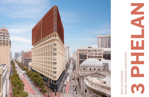
3 PHELAN
A0.0 COVER SHEET
A1.0 REGULATORY
A1.1 OVERVIEW SHEET
A1.2 ZONING ANALYSIS
A2.0 SITE CONDITIONS
A2.1 SUN PATH
A2.2 INTERIOR SUNLIGHT
A2.3 WIND ROSE DIAGRAM
A2.4 DEMOGRAPHICS
A2.5 SITE CONTEXT
A2.6 TRANSIT MAP
A2.7 SITE HISTORY
A2.8 SITE HISTORY
A3.0 USER REQUIREMENTS
A3.1 PROGRAM ANALYSIS
A3.2 PROGRAM ANALYSIS
A3.3 PROGRAM ANALYSIS
A3.4 PROGRAM ANALYSIS
A4.0 ADDITIONAL ANALYSIS
A4.1 ADDITIONAL ANALYSIS
A4.2 ADDITIONAL ANALYSIS
A4.3 ADDITIONAL ANALYSIS
A5.0 DESIGN SYNTHESIS
A5.1 EXPLANATORY
A5.2 PROGRAM DIAGRAM
A5.3 CIRCULATION DIAGRAM
A6.0 LIFE/SAFETY EGRESS
A6.1 FIRST FLOOR EXISTING
A6.2 FIRST FLOOR ADDITION
A6.3 TYPICAL UNIT PLAN
A7.0 SITE PLAN AND BUILDING PLANS
A7.1 FIRST FLOOR EXISTING
A7.2 FIRST FLOOR ADDITION
A7.3 TYPICAL UNIT PLAN
A7.4 ENLARGED FLOOR PLAN
A7.5 ROOF PLAN
A8.0 ELEVATIONS
A8.1 NORTH ELEVATION
A8.2 WEST ELEVATION
A9.0 BUILDING SECTIONS
A9.1 SECTION 2
A10.0 STRUCTURE
A10.1 STRUCTURAL RESEARCH
A10.2 STRUCTURAL ISO
A11.0 BUILDING INTEGRATION – WALL SECTIONS AND DETAILS
A11.1 CHUNK 1
A11.2 CHUNK 2
A11.3 WALL SECTIONS
A11.4 DETAILS
A11.5 STAIR SECTION AND PLANS
A12.0 ENVIRONMENTAL SYSTEMS
A12.1 SEASONAL ENVIRO
A12.2 SEASONAL ENVIRO
A12.3 3D HVAC AXON
A12.4 HVAC PLAN FFA
A12.5 HVAC PLAN TYP
A13.0 BUILDING PERFORMANCE
A13.1 BUILDING PERFORMANCE
A14.0 ENVIRONMENTAL IMPACT
A14.1 ENVIRO IMPACT
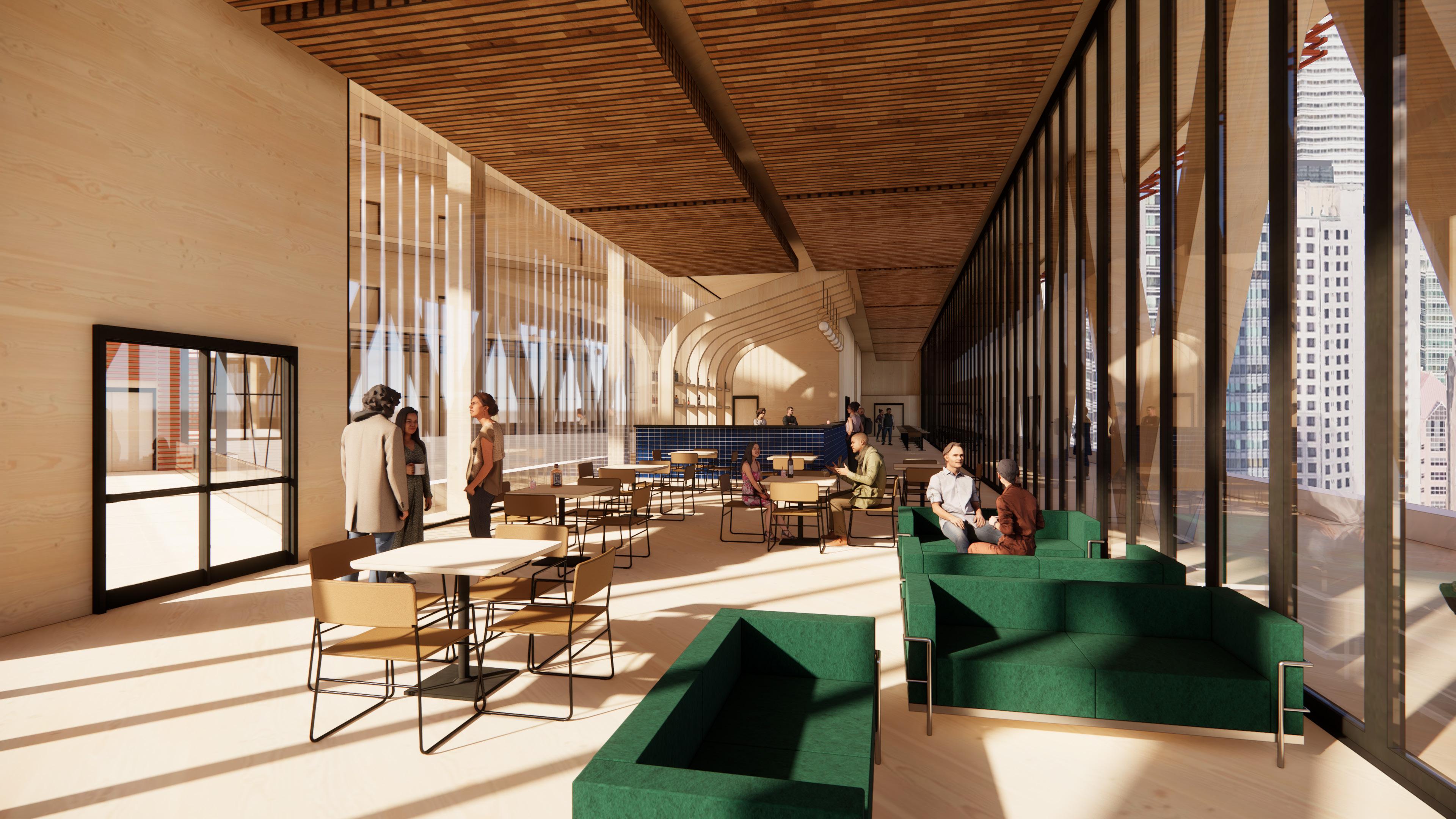
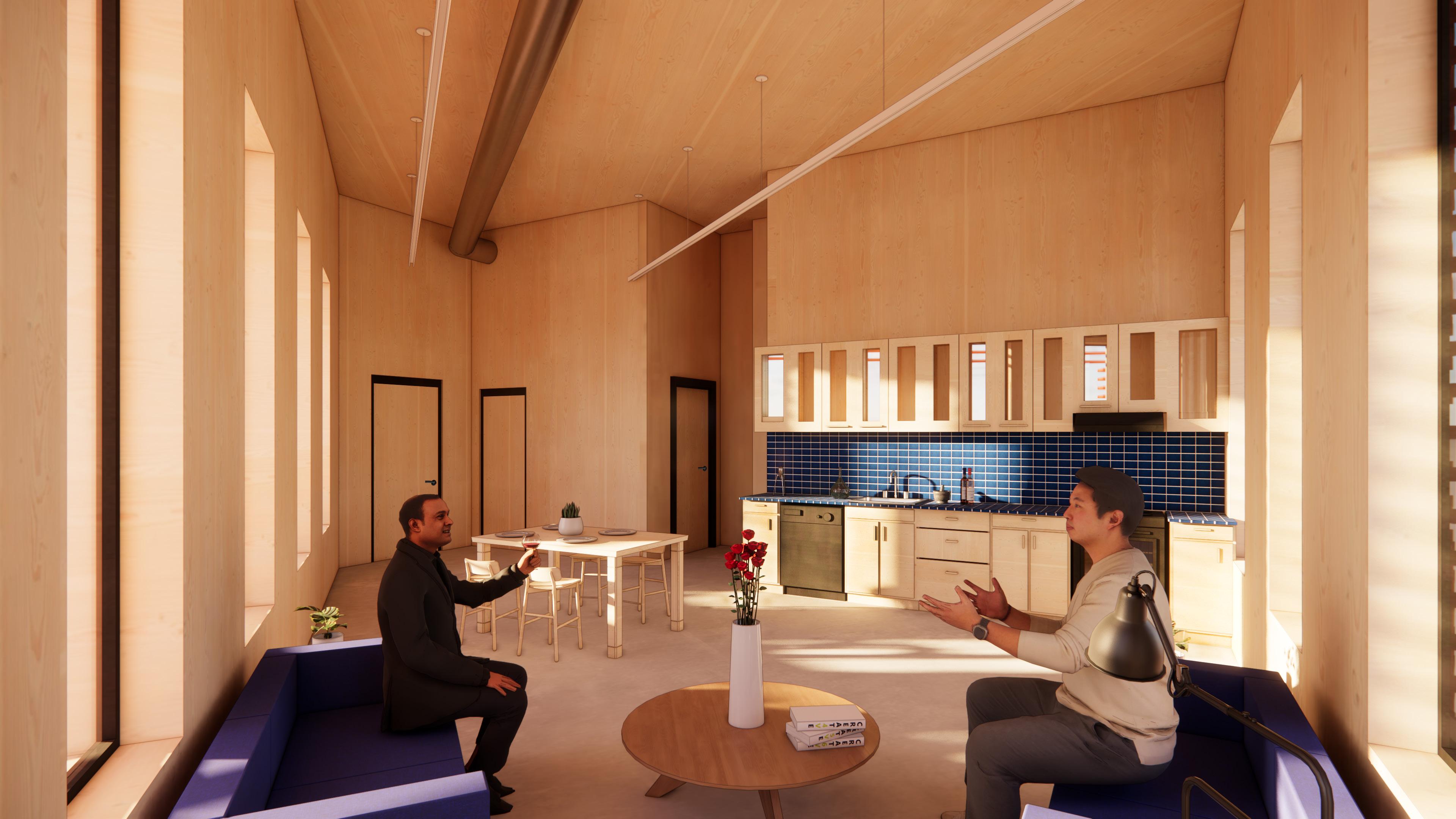
A15.0 PERSPECTIVES AND ADDITIONAL 3D VIEWS
A15.1 EXTERIOR RENDER
A15.2 EXTERIOR RENDER
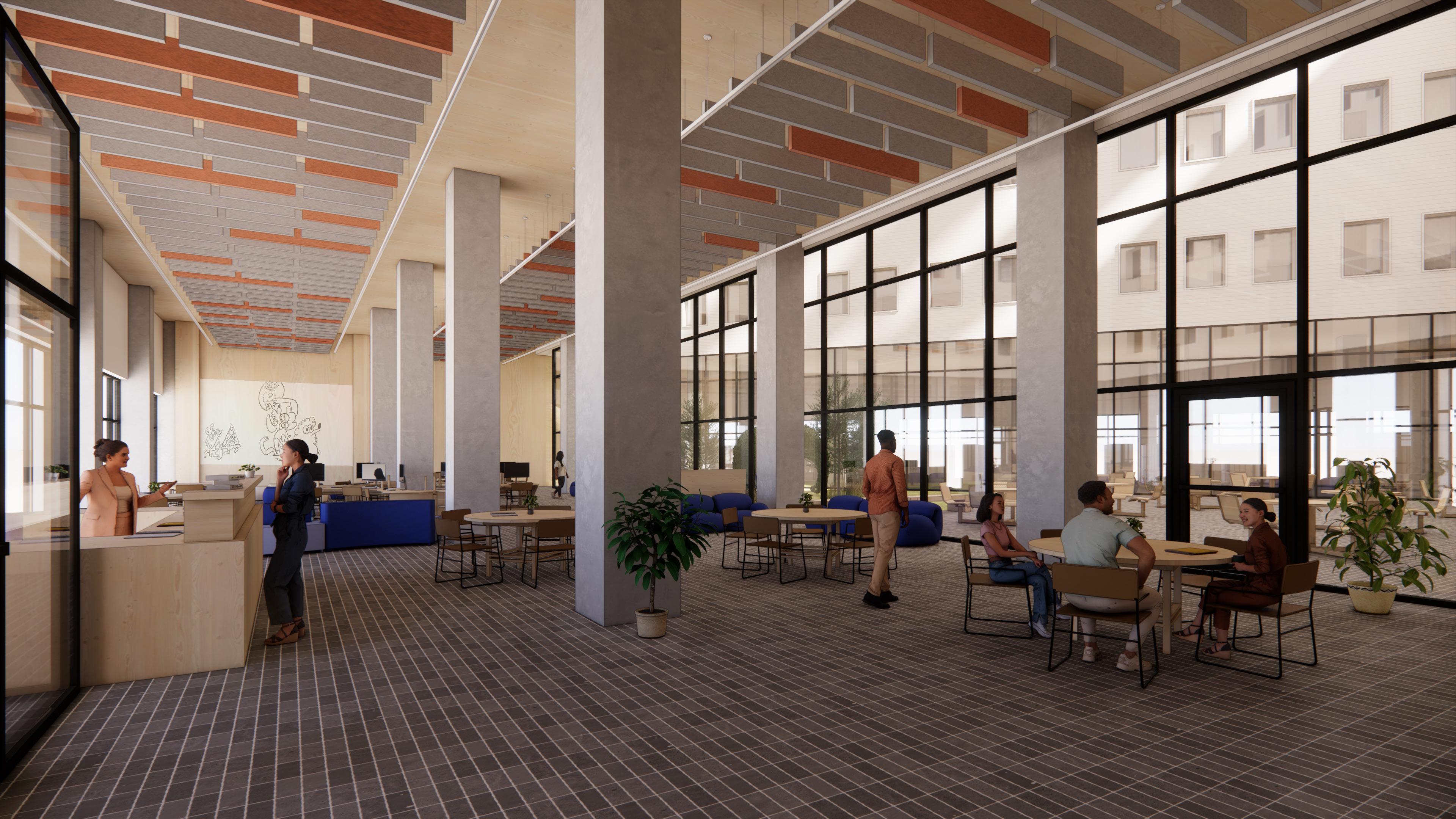
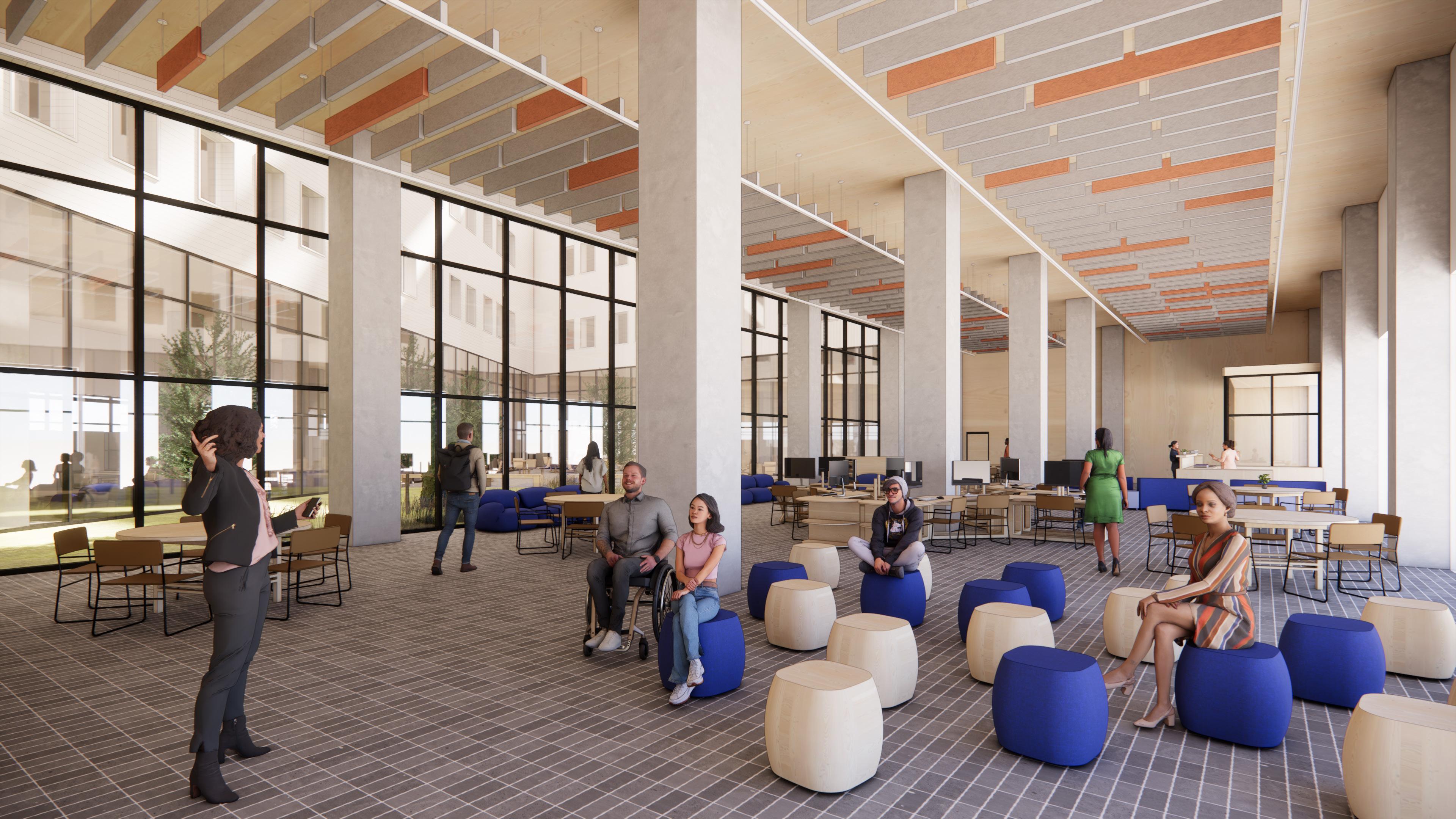
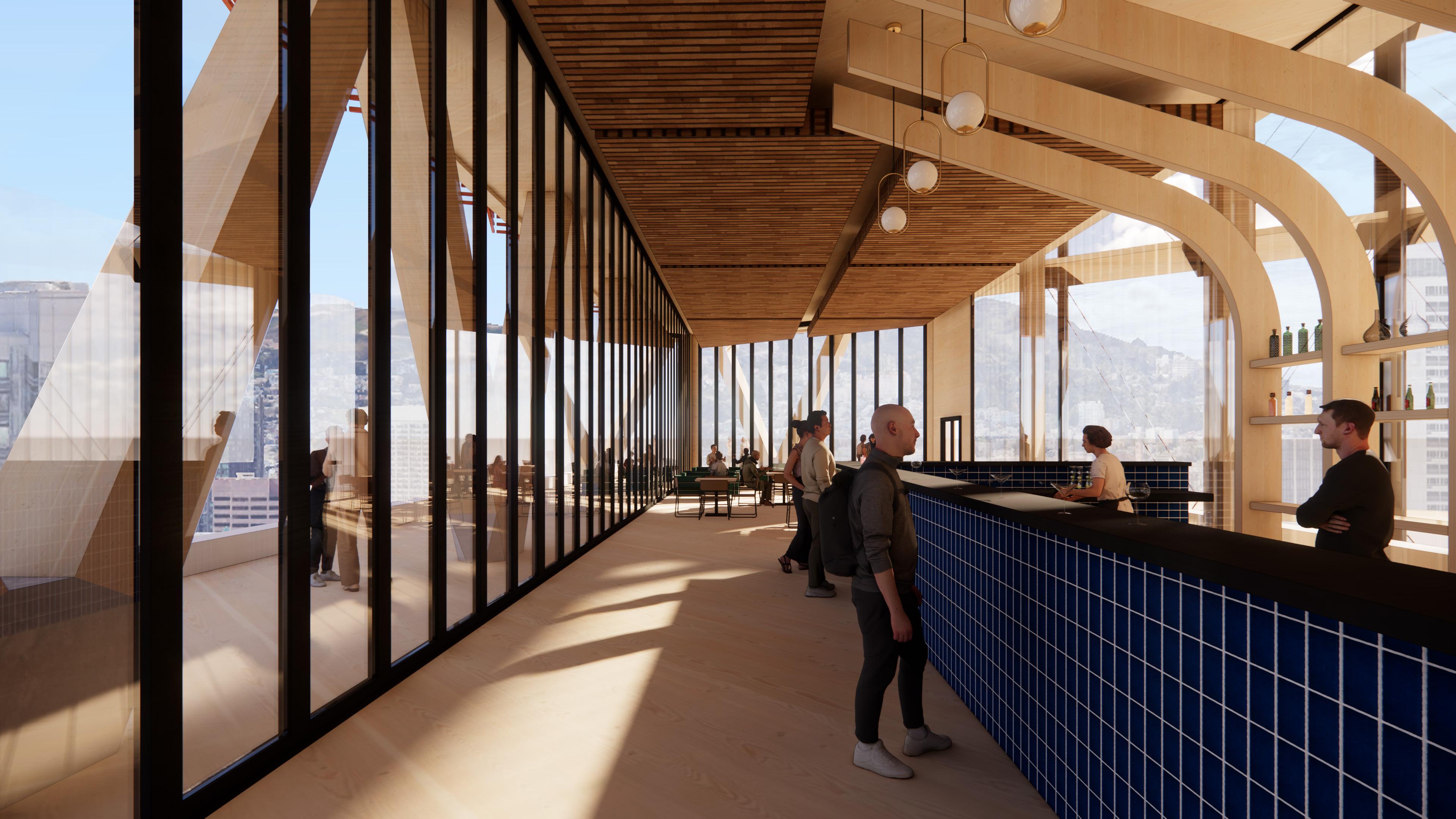
A15.3 INTERIOR RENDER
A15.4 INTERIOR RENDER
A15.5 INTERIOR RENDER
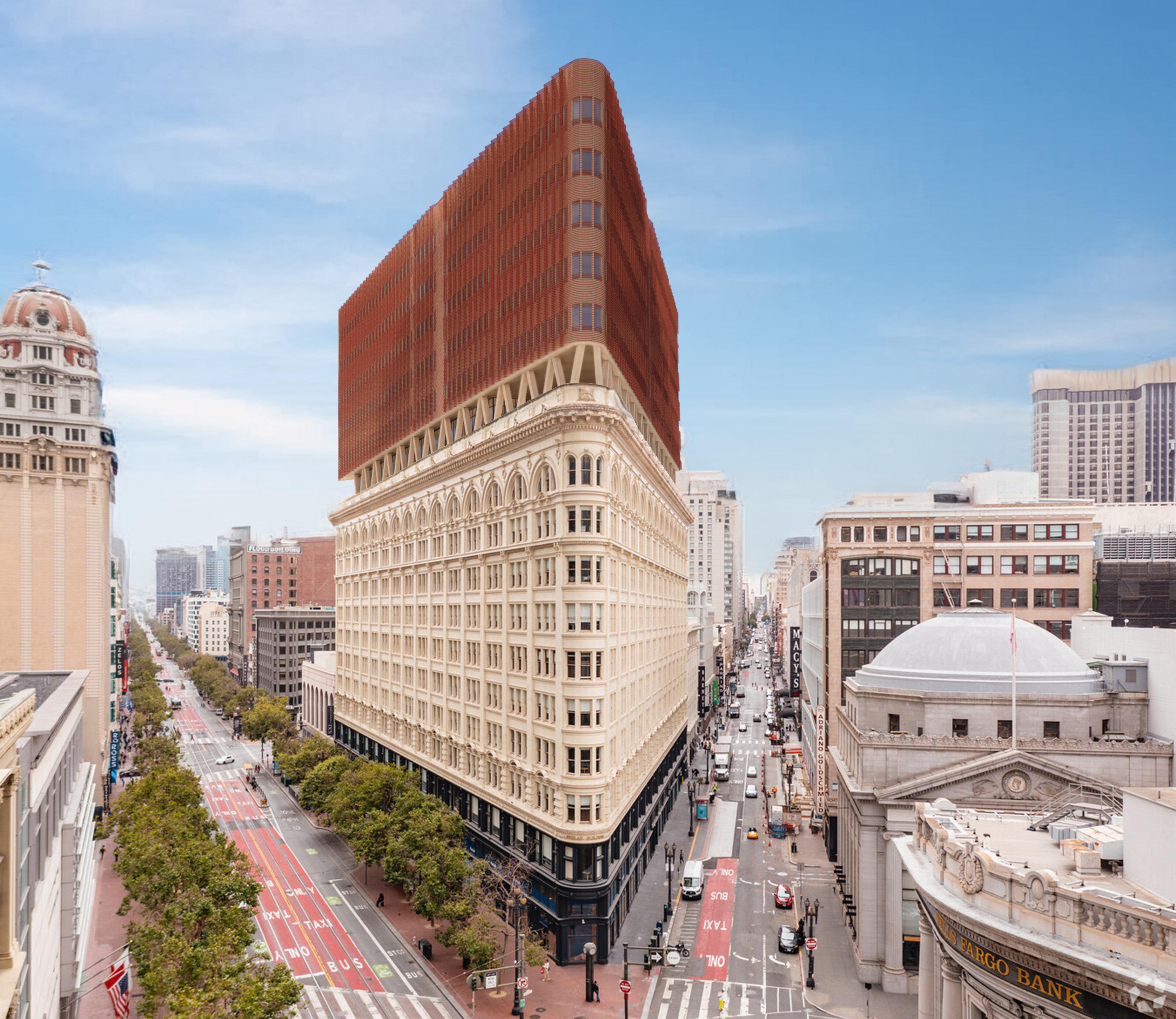
PROPOSED
REGULATORY REQUIREMENTS NARRATIVE
The Phelan Building benefits from exemptions to zoning codes attributed to its historical significance and the age of both the building and the property, allowing it certain freedoms in new design. Following the San Francisco earthquake of 1906, the municipality of San Francisco would begin adopting new ordinances regulating the construction of new buildings. It would not be until 1921 that the city of San Francisco would begin implementing zoning code ordinances regulating public and private land uses. Later in 1978, the California Building Standards Code would be implemented to consolidate building standards into a single code.
The current 80’ height limit does not apply to the Phelan Building as the code was set for this building after it was constructed, leaving it grandfathered in from the San Fransisco Municipal Code. This is the case for many of the surrounding buildings as well. The setback for this building does not exist as the property line is the original structure’s exterior walls. This influenced the vertical expansion to be inset from the original footprint of the building, giving the building a unified feel while respecting the historical podium. Parking is not required by the SFMC as the city is rich in public transportation. The Phelan Building, benefiting from historical exemptions and unique zoning considerations, where its rich architectural history crossroads with modern design freedoms and transportation-centric urban planning.
ZONING ANALYSIS CONSTRUCTION & BUILDING CODE ANALYSIS
PROJECT ADDRESS:
760 Market Street, San Fransisco, CA, 94102
ZONING REQUIREMENTS
Zone: C-3-R
Height: 80’ (not applicable to this property)
San Fransisco Building Code 210.2
CODE REFERENCES
International Building Code (IBC)
San Fransisco Municipal Code
California Building Code
California Energy Code
FIRE RATINGS
Between Units: 3 Hour
PLUMBING
Water Closets: 1 per dwelling unit
Lavatories: 1 per dwelling unit
Bath/Shower: 1 per dwelling unit
Drinking Fountains: NR
Service Sinks: 1 kitchen sink per dwelling unit,
1 automatic clothes washer per 20 dwelling units
OCCUPANCY
R-2
MAX OCCUPANCY
2,214 Occupancy
CONSTRUCTION TYPE
IV-A
FAR VALUE
6.0 to 1
PARKING REQ.
Not Required - SF Municipal Code
PARCEL AREA
31,498 SF
ALLOWABLE BUILDING AREA
188,988 SF
ACTUAL BUILDING AREA
Existing: 327,339 SF
New Construction: 95,650 SF
ALLOWABLE BUILDING HEIGHT
80’ - Property Grandfathered in
ACTUAL BUILDING HEIGHT
258’ -Property Grandfathered in
SETBACKS
0’ - Not Applicable
EGRESS COMPONENTS
California Building Code
FIRE REQUIREMENTS
Bearing Walls: 3 Hours
Roof: 1.5 Hours
Floor: 2 Hours
Exit Corridor: 3 Hours
Shaft: 2 Hours
Structural Frame 3 Hours
Non-Bearing: 0 Hours
California Building Code
Zoning
C-3-R Setbacks
Front: N/A
Side: N/A
Rear: N/A
80’ - N/A for this property
0’ Setback is property line
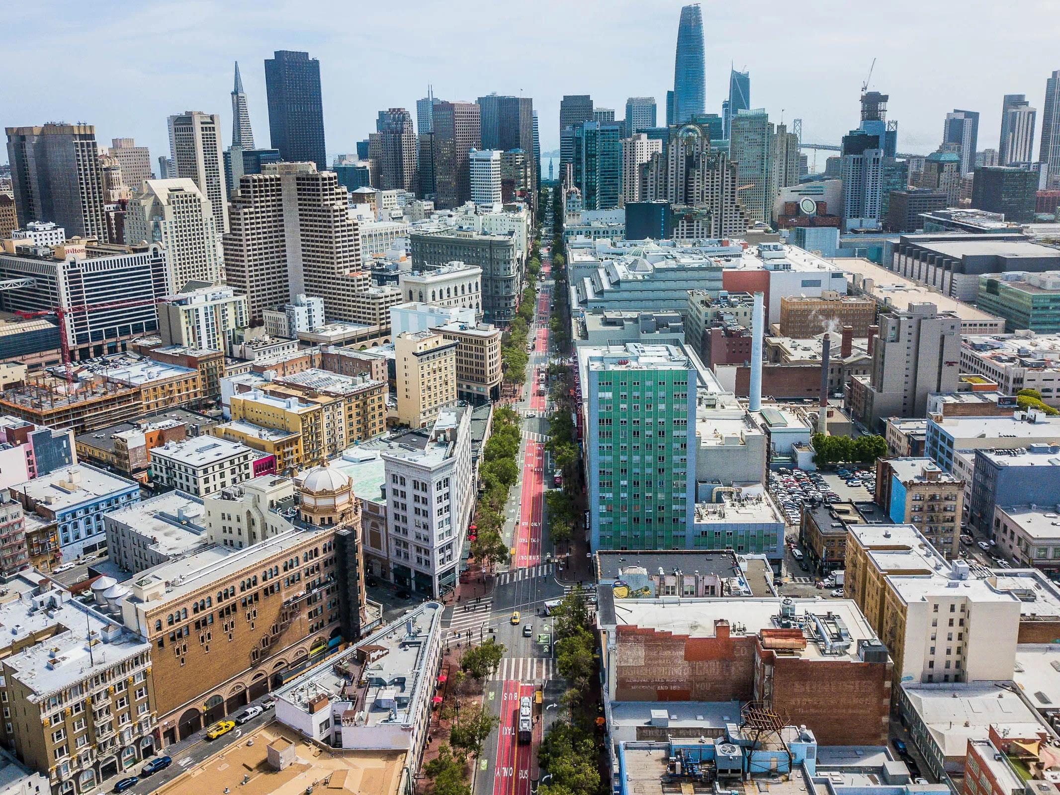
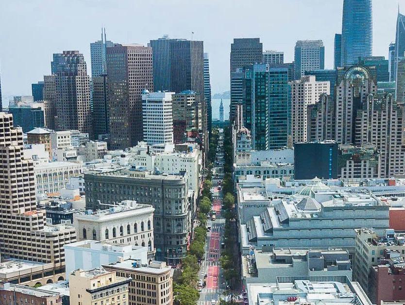
Choosing downtown San Francisco for a vertical expansion atop another building for an affordable housing project was a strategic decision with numerous benefits. Firstly, downtown locations offer access to employment opportunities, transportation networks, and urban amenities, facilitating economics and enhancing residents’ quality of life. By situating the affordable housing project in the heart of the city, residents can easily access job centers, educational institutions, cultural attractions, and recreational facilities, fostering a vibrant and inclusive community.
Vertical expansion maximizes land use efficiency in densely populated urban areas where available space is limited. By building upwards, the project minimizes the use of valuable land resources while still meeting the growing demand for housing in a high-demand market like San Francisco. This approach supports sustainable urban principles, promoting compact, transit-oriented growth and reducing urban sprawl and car dependence. Locating the affordable housing project in downtown San Francisco promotes social inclusion and diversity by providing housing options in a mixed-use, mixed-income environment. Residents have the opportunity to live in close proximity to people from diverse backgrounds and income levels, fostering social cohesion and community resilience.
Additionally, the iconic skyline of downtown San Francisco offers unmatched views and a unique living experience for residents, enhancing the affordable housing and contributing to its long-term sustainability.
Studying the times of day the sun will be directly shining on a building is vital for architectural design and energy efficiency, as it informs decisions regarding shading strategies, window placement, and thermal comfort measures, reducing the building’s reliance on artificial cooling and heating systems while enhancing occupant comfort.
JUNE 21
72° 27° SUMMER SOLSTICE
WINTER SOLSTICE DECEMBER 21
Understanding solar exposure patterns allows for the implementation of passive design principles, minimizing solar heat gain and glare, thus optimizing indoor environmental quality and reducing energy consumption over the building’s lifespan.
Studying the different seasonal wind patterns on a building is essential for optimizing natural ventilation strategies and minimizing energy consumption by strategically locating openings and designing airflow pathways, ensuring comfortable indoor environments year-round. Additionally, this analysis informs design decisions regarding structural integrity, leading to adjustments in the building’s design to accommodate wind loads and design pressures, thus enhancing safety and durability.
40.4
Median Age About the same as the figure in the San Francisco-OaklandBerkeley, CA Metro Area: 40.6 About 10 percent
Population by age range
Sex
Race & Ethnicity
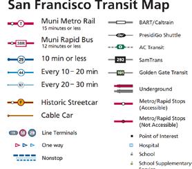
CABLE CAR
MUNI RAPID BUS
MUNI BUS
MUNI METRO RAIL
BART
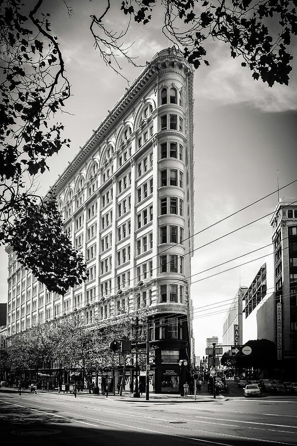
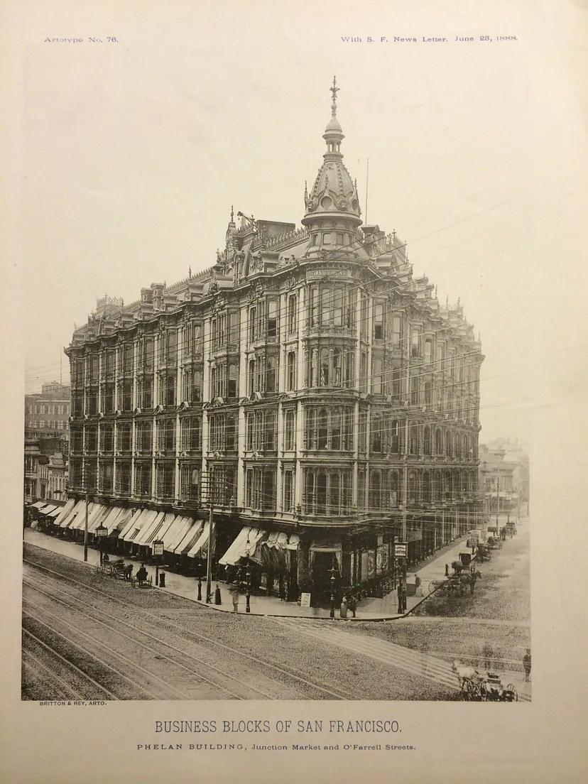
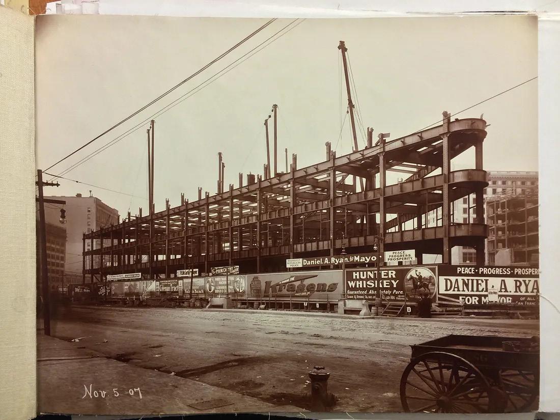
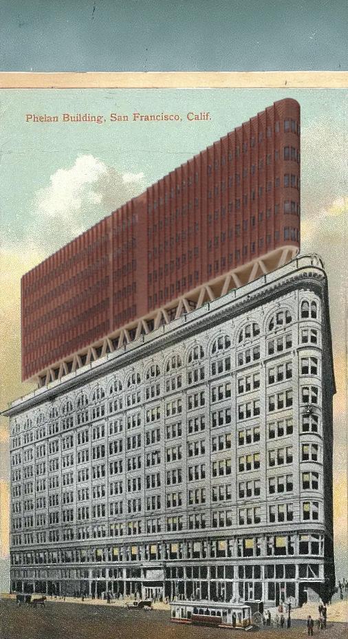
The original Phelan Building stood as an architectural marvel in San Francisco, a testament to the city’s burgeoning prosperity in the late 19th century. Completed in 1881, this grand edifice epitomized the opulence and ambition of the Gilded Age. Designed by architect William Curlett, the building’s ornate facade featured intricate detailing in the Second Empire style, adorned with elaborate cornices and arched windows. Rising proudly along Market Street, it served as a beacon of commerce and culture, housing an array of prestigious businesses and offices. Its interiors were equally impressive, boasting lavish marble staircases, polished wood paneling, and elegant chandeliers. However, tragedy struck on April 18, 1906, when the Great San Francisco Earthquake reduced the Phelan Building to rubble, leaving behind memories of a bygone era and a symbol of resilience in the face of adversity.
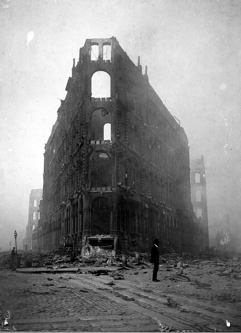
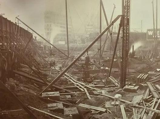
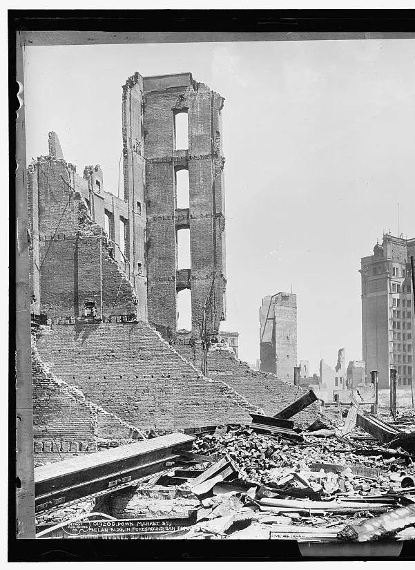
San Francisco is located in a seismically active region, prone to earthquakes due to its proximity to the San Andreas Fault. Throughout history, the city has experienced several significant earthquakes, the most notable being the 1906 San Francisco earthquake. The 1906 San Francisco earthquake struck on April 18th, resulting in widespread devastation. It is estimated to have had a magnitude of around 7.8, making it one of the most powerful earthquakes to hit California in recorded history. The earthquake, along with subsequent fires that raged through the city for several days, caused immense destruction, resulting in the loss of thousands of lives and the displacement of hundreds of thousands of residents.
The Phelan Building, named after James D. Phelan, a prominent politician and philanthropist, was one of the many structures in San Francisco affected by the earthquake. The building, located at the intersection of Market Street and O’Farrell Street, suffered significant damage as a result of the seismic activity. The significance of the earthquake in relation to the Phelan Building lies in its impact on both the physical structure and the historical context. The earthquake not only caused structural damage to the building but also symbolized the vulnerability of even well-constructed edifices in the face of such natural disasters.
The construction of the Phelan Building reflects the architectural style prevalent during the early 20th century. It is a steel-framed structure, which was a common construction method during that period, especially in areas prone to earthquakes. Steel framing provides strength and flexibility, allowing buildings to withstand the lateral forces generated by seismic activity.
The exterior of the Phelan Building is clad in a combination of materials commonly used in Beaux-Arts architecture, which was popular during the early 20th century. Beaux-Arts buildings often feature elaborate ornamentation and classical design elements. The Phelan Building’s façade incorporates elements such as terra cotta, a type of ceramic material, which was frequently used for decorative detailing. Terra cotta allowed architects to add intricate designs and sculptural elements to the building’s exterior.
The structural design of the Phelan Building ingeniously integrates steel and concrete, allowing for a potential vertical expansion of up to 10 stories. This forward-looking approach ensures that the building can accommodate future growth seamlessly. By strategically positioning beams, columns, and foundations, engineers have guaranteed the building’s ability to adapt to evolving needs while maintaining its structural integrity. This thoughtful planning underscores the building’s resilience and capacity for sustainable development in an ever-changing urban environment.


The chosen program of affordable housing was selected based on the proximity to essential amenities such as grocery stores, schools, and healthcare facilities, reflecting a thoughtful approach to community well-being and accessibility. By situating the housing development near grocery stores, residents can easily access fresh and nutritious food options, promoting healthy living and food security. The availability of schools nearby ensures that families have convenient access to quality education for their children, fostering academic success and lifelong learning opportunities. Additionally, the proximity to healthcare facilities ensures that residents have access to essential medical services and support, promoting overall health and well-being within the community. This strategic placement of affordable housing near these amenities not only enhances the quality of life for residents but also fosters a sense of cohesion and connectivity within the neighborhood. The integration of affordable housing into areas with existing amenities contributes to the sustainable utilization of urban infrastructure and resources, maximizing efficiency and minimizing environmental impact. This approach aligns with principles of smart urban planning and inclusive community development, prioritizing access to essential services for all residents, regardless of socioeconomic status.
PROGRAM USAGE
BAR APARTMENTS
Studying the times of day people use a program in a building is crucial for optimizing its functionality and resource allocation, ensuring that services and facilities are available when they are most needed, thus enhancing user satisfaction and maximizing efficiency in the building’s operations. Understanding usage patterns enables informed decisions regarding staffing, maintenance schedules, and facility management, ultimately leading to a more responsive and user-centric built environment.
OFFICES
PHELAN BUILDING | ROOM
APARTMENT FLOORS
FLOOR USES | EXPOSING FLOOR PROGRAM USAGE
NEW PROGRAM - APARTMENTS
NEW PROGRAM - BAR, APARTMENT OFFICES
EXISTING PROGRAM - OFFICES
NEW PROGRAM - LIBRARY, ART GALLERY
APARTMENTS EXISTING - OFFICE
COURTYARD
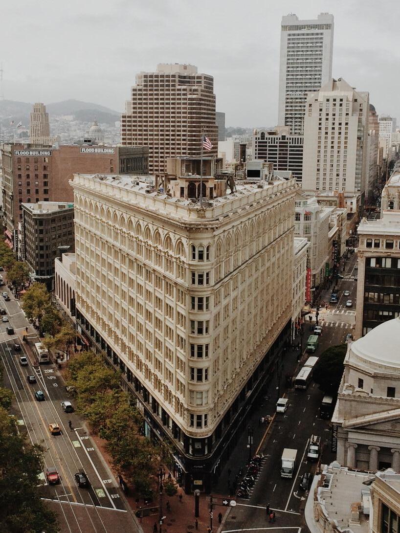
PHELAN BUILDING (EXISTING)
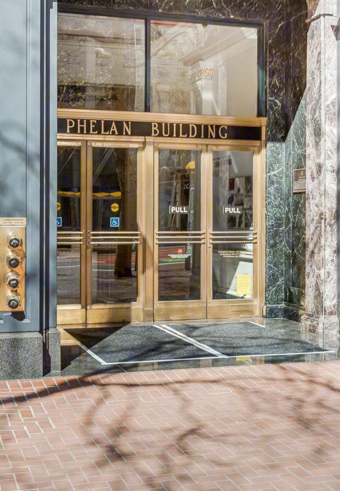
The existing Phelan building serves at the most crucial precedent in the project. The historical Phelan Building serves as the podium for the proposed vertical expansion. With this iconic structure serving as the host for the addition, the forms guides the addition up into the sky. Providing an already unique building shape, the existing conditions shaped the addition into the flatiron mass nestling into the San Fransisco skyline.
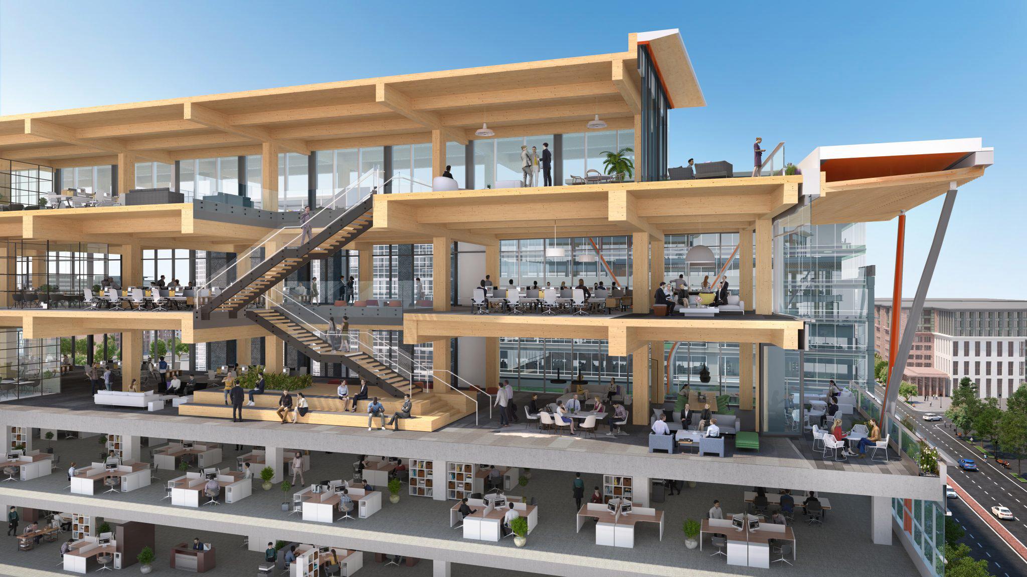
CLT
Choosing Cross-Laminated Timber for the building construction was preferred due to its sustainability, strength, and efficiency. CLT’s use of sustainably sourced wood reduces environmental impact, while its strength allows for innovative designs and quick construction. CLT provides excellent thermal and acoustic performance, enhancing both energy efficiency and occupant comfort.
STRUCTURE
Using V-shaped columns to transfer the load from the load-bearing walls down to the existing columns of the building underneath optimizes structural support and distributes weight effectively, ensuring stability and minimizing the need for additional structural modifications.
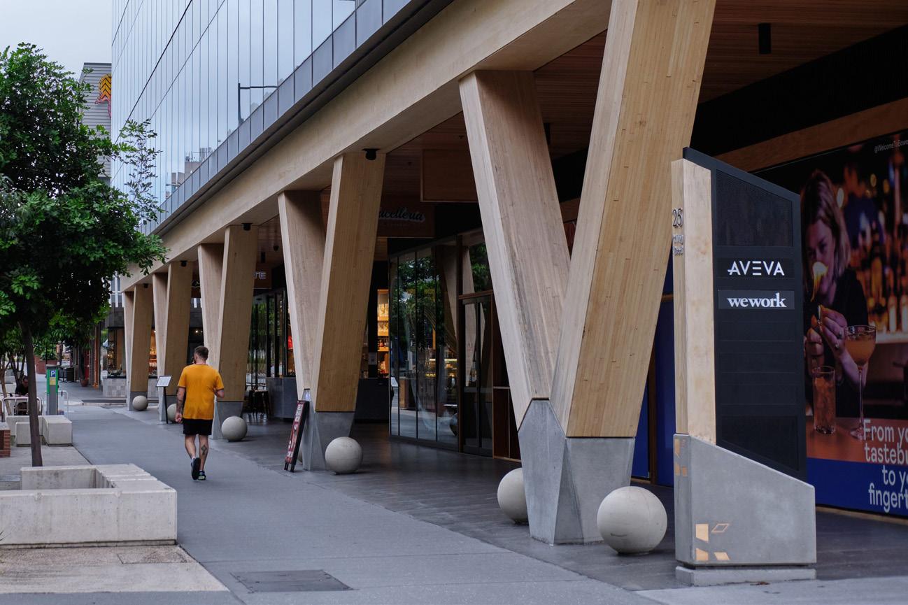
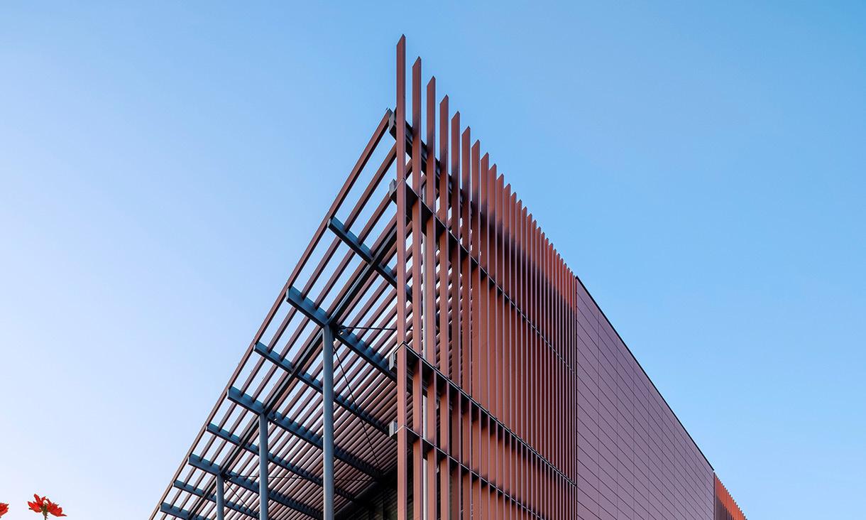
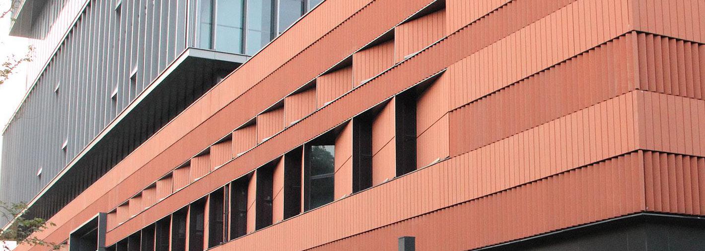
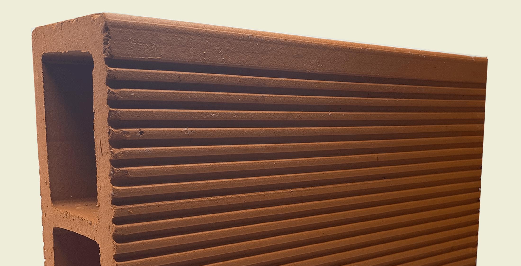
TERRACOTTA BAGUETTES
Opting for terracotta baguettes for the cladding of the building was an excellent decision due to their aesthetic appeal, durability, and sustainability; they enhance the facade, withstand weathering, and are made from natural materials, aligning with modern architectural preferences for environmentally friendly materials, while also serving as effective sun shading elements. Terracotta is frequently utilized in California due to its suitability for sun shading in the region’s climate, where California’s natural stone is not optimal for construction.
$89,736
$136,629
Per Capita Income Median Household Income
About 25 percent higher than the amount in the San Francisco-Oakland-Berkeley, CA Metro Area: $71,052
Nearly double the amount in California: $46,661
About 10 percent higher than the amount in the San Francisco-Oakland-Berkeley, CA Metro Area: $128,151
About 1.5 times the amount in California: $91,551
10.4%
Persons Below Poverty Line
About 10 percent higher than the rate in the San Francisco-Oakland-Berkeley, CA Metro Area: 9.2%
About 80 percent of the rate in California: 12.2%
Transportation to Work
29.5 Minutes
Mean Travel Time to Work
About the same as the figure in the San Francisco-Oakland-Berkeley, CA Metro Area: 30.3
A
Means of Transportation to Work
Seniors 65 and older
414,553
Number of Housing Units
Units and Occupancy San Francisco-Oakland-Berkeley, CA Metro Area: 1,877,839
Types of Structure
Value
$1,343,700
Median Value of Owner Occupied Housing Units
About 20 percent higher than the amount in the San Francisco-Oakland-Berkeley, CA Metro
Value of Owner Occupied Housing Uints
EXISTING MATERIALS
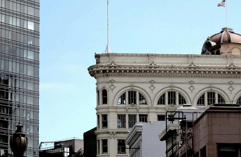
Characteristics of Glazed Architectural Terra-Cotta as a Building Material
Glazed architectural terra-cotta shares several material properties with traditional masonry like brick or stone, yet it also boasts distinct qualities that set it apart. Understanding these unique characteristics is essential when utilizing glazed architectural terra-cotta in construction projects.
Challenges in Identification: Despite being a prevalent material in urban environments, glazed architectural terra-cotta often goes unnoticed due to the diverse range of glazing options available. Its ability to mimic stone finishes with precision has led many to mistake it for granite or limestone. This aspect can surprise both building owners and architects who discover the true nature of their structures.
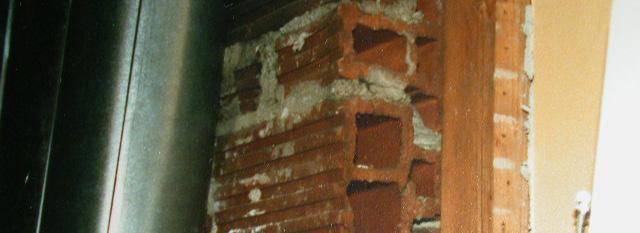
Two Distinct Systems: Historically, glazed architectural terra-cotta has served in two distinct capacities: as a component within traditional load-bearing masonry walls in shorter buildings and as a cladding material in high-rise construction. When used as cladding, it typically requires a comprehensive metal anchoring system for attachment, presenting a stark contrast to its minimal anchoring in load-bearing walls. Consequently, deterioration tends to be less pronounced in the former scenario compared to the latter, where severe degradation is common.
Complex Deterioration: The degradation process of glazed architectural terra-cotta, especially when employed as cladding, is inherently intricate. Deterioration sets off a chain reaction, impacting glazed units, mortar, metal anchors, and masonry backfill, leading to a cascade of failures throughout the system. Such complexity distinguishes it from other masonry systems where material failure is typically less convoluted.
Design Flaws: A primary cause of deterioration in glazed architectural terra-cotta systems often stems from misconceptions about its properties. Historically, it was erroneously regarded as inherently waterproof, leading to the omission of crucial components such as flashing, weep holes, and drips. This oversight has proven detrimental, as evidenced by early water-related failures in many glazed architectural terra-cotta clad buildings.
Patterson Tiller, D. T. (1979, June). 7 preservation briefs. National Parks Service.
DESIGN POSITION STATEMENT
Our approach involves delicately tracing the existing building’s outline to seamlessly integrate new floors. By subtracting specific masses, we prioritize sunlight, views, and ventilation, enhancing the living conditions for residents and fostering a healthier urban environment. This strategy not only enriches the quality of life for occupants but also contributes to sustainable and equitable urban development, aligning with our commitment to affordable housing. Spaces that have been created maximize affordability without compromising comfort or functionality, making urban living more accessible to diverse socioeconomic backgrounds.
PROJECT GOALS DESCRIPTION
Foster a sustainable environment for affordable housing
Use sustainable building materials and practices
Provide affordable housing in an unafforable market
Provide an experience not typical to affordable housing
EXISTING
Original structure mass
EXTRUDE
Trace original footprint and extrude upwards; expanding existing footprint.
DEDUCT
Subtract masses from previous phase; allows for additional sunlight and breaks in massing.
FRAME
Add structure to mass, allow form to read di erent, but operate cohesivley
WRAP
Add terraco a cladding to mass, allow passive sunlight to enter while protecting from solar heat gain
EXISTING - FLOORS 2-10
OFFICES
ADDITION - FLOORS 2-6
MICRO UNITS ONE BEDROM UNITS TWO BEDROOM UNITS THREE BEDROOMS UNITS
ADDITION - FLOOR 1
OUTDOOR SPACE OFFICE BAR BIKE SHOP MECHANICAL
EXISTING - FLOOR 1
LIBRARY
EXISTING - FLOOR 1
ART GALLERY RESIDENTIAL ENTRANCE
CIRCULATION PATHS
EXISTING
VERTICAL CIRC. TIES INTO EXISTING CIRCULATION ELEMENTS.
LIFE SAFETY NARRATIVE
Designing life safety and egress for a vertical expansion around an existing building, especially one with a unique shape like a flatiron, presents formidable challenges. Adding additional floors while maintaining structural integrity and compliance with building codes requires meticulous planning and expertise. The irregular shape of flatiron buildings complicates egress, as asymmetrical layouts can disrupt efficient evacuation routes and necessitate customized solutions. Vertical expansions require consideration of accessibility requirements to ensure equitable evacuation options for all occupants, including those with mobility challenges. Retrofitting existing structures to meet these standards while addressing the unique challenges of flatiron-shaped buildings. The complexity of designing life safety and egress for vertical expansions around existing and flatironshaped buildings arises from a combination of structural constraints, regulatory considerations, and the need to preserve historical integrity while considering occupant safety and accessibility.
ZONING SETBACKS
Not Applicable
DIST. FROM PROPERTY LINE TO BUILDING
0’ FAR
6.0 TO 1
REQ. PARKING SPACES
Not Applicable
ADA - Not Applicable
1/32" = 1'-0"
1/32" = 1'-0" ROOF PLAN
ROOF DRAINS
1/32" = 1'-0"
WEST ELEVATION
1/32" = 1'-0"
258’ - 9”
238’ - 9” ADDITION PARAPET
223’ - 9” ADDITION L 6
208’ - 9” ADDITION L 5
ADDITION L 3
193’ - 9” ADDITION L 4
ADDITION L 2
178’ - 9”
ADDITION L 1
158’ - 9”
L 1
0’ - 0”
PHELAN BUILDING
STRUCTURAL NARRATIVE
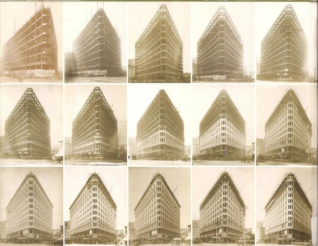
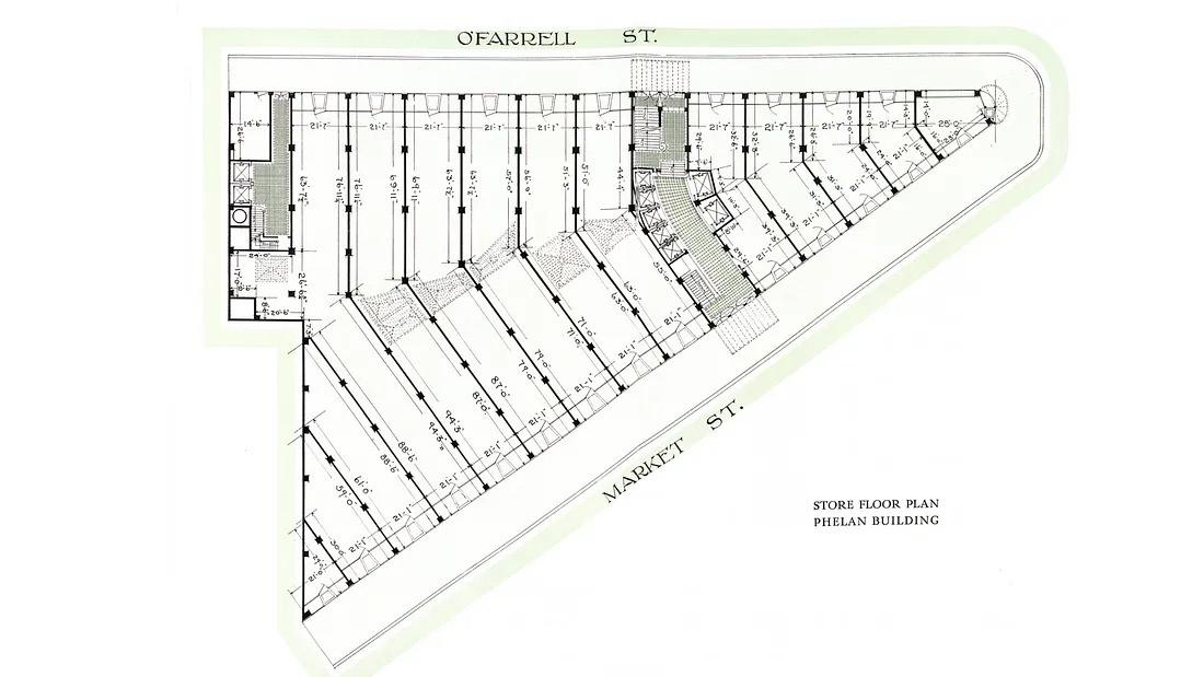
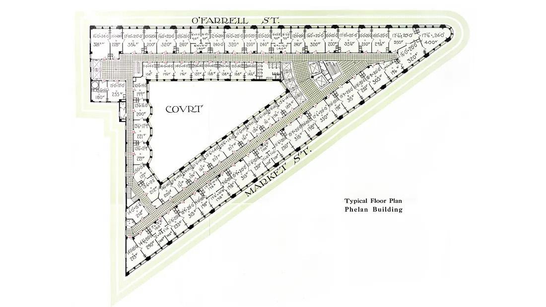
The Phelan Building is a flatiron-shaped building located at the intersection of Market and O’Farrell Streets in downtown San Francisco. The original Phelan Building was a six-story structure completed in 1881. Following the 1906 San Francisco earthquake, the Phelan building was demolished due to the heavy damage it had sustained from the earthquake and subsequent fires that took place in the city. In October 1907, James Phelan Jr. and architect William Curlett designed and constructed the current Phelan Building. Completed in September of 1908, the Phelan building is a Renaissance-Baroque style flatiron building containing 11 stories with roughly 300,000 square feet. The existing Phelan Building is constructed with a steel frame encased in concrete. The building’s existing structure can support up to 10 additional floors of steel and concrete framed construction.
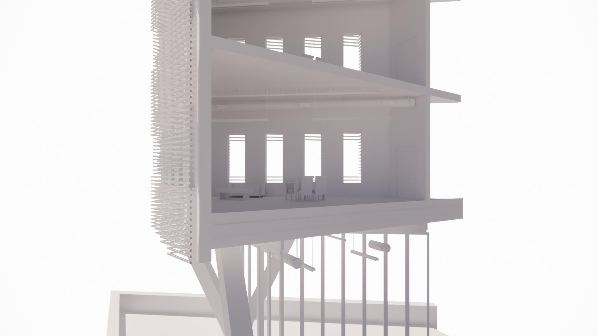
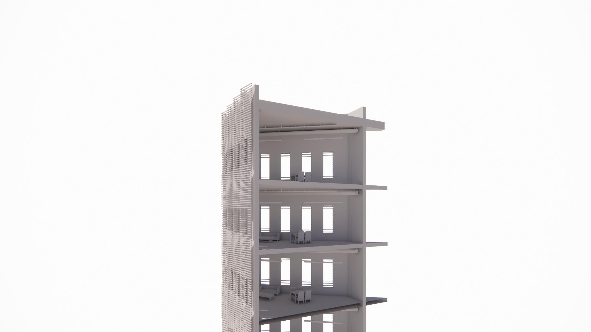
Structurally, the new addition consists of six CLT composite floors supported by a series of CLT shear walls that run from the second floor of the addition up to the roof. These new CLT floors and walls are supported by a system of CLT columns on the first floor of the addition that transfers loads from the new construction to the existing column structure of the Phelan Building. CLT Load bearing and shear walls were chosen as the primary structure for the addition due to their lightweight compared to steel and concrete construction. The physical properties of CLT elements help to absorb and dissipate seismic loads, reducing the amplitude of vibrations transmitted throughout the structure.
COLUMNS
CLT columns transfer loads from shear walls and floor plates to existing column structure.
CLT FLOOR PLATES
Composite CLT floor plates are supported by shear walls as well as columns.
SUSPENDED WALKWAYS
Outdoor suspended walkways connect new addition and existing floor plates.
LOAD-BEARING/SHEAR WALLS
Interior shear walls help to resist seisimic forces while also providing separation between units.
ROOF
Composite roof is supported by shear walls and protects occupants from the elements.
EXTERIOR SHEAR WALLS
Provides further support against lateral forces and functions as the envelope of the addition.
LEVEL ONE - EXISTING
1/32" = 1'-0"
1/32" = 1'-0"
MATERIAL NARRATIVE
CLT was selected as the material for both interior and exterior walls due to its sustainability and strength. As an engineered wood product, CLT promotes environmental conservation by utilizing timber from sustainably managed forests, while its cross-laminated layers provide exceptional strength and stability, allowing for efficient construction and innovative architectural designs. The use of CLT for interior walls offers flexibility in space configuration and acoustical performance, enhancing the overall comfort and functionality of the building.
Terracotta baguettes were chosen to clad the building exterior to protect it from solar heat gain while adding aesthetic appeal. The natural thermal properties of terracotta help regulate indoor temperatures by providing insulation, reducing the need for excessive cooling during hot weather. Additionally, the baguettes serve as
INTEGRATION NARRATIVE
The goals and organization of the project serve as factors in the design of the wall section, its materiality, and details, ensuring alignment with the project’s objectives. In the case of integrating CLT columns into existing steel columns, the design prioritizes structural integrity and integration, using techniques such as steel connection plates or bolts to securely fasten the CLT columns to the steel framework. This approach not only ensures stability but also minimizes construction time and disruption.
The selection of terracotta baguettes for solar protection reflects the project’s commitment to sustainability and occupant comfort. The design of how the baguettes connect to the wall emphasizes both functionality and aesthetics, with thought given to attachment methods that maintain the integrity of the building envelope while allowing for efficient installation and future maintenance. The connection details between bearing walls and floors are designed to optimize load transfer and structural stability, with a focus on simplicity, efficiency, and durability. Techniques such as anchor bolts or steel connections are utilized to securely anchor the walls to the floors, ensuring against lateral loads and seismic forces.
STRUCTURAL CLT WALLS
TERRACOTTA BAGUETTES
FIRE SUPPRESSION SPRINKLERS
HVAC
DROP LIGHTING
OPERABLE WINDOWS
CAVITY, SOUND BARRIER, & INSULATION
TRANSFER V COLUMN TO EXISTING COLUMNS
NANA WALL
CLT COMPOSITE ROOF
STRUCTURAL CLT WALLS
TERRACOTTA BAGUETTES
FIRE SUPPRESSION SPRINKLERS
HVAC
DROP LIGHTING
OPERABLE WINDOWS
CLT COLUMN
CONCRETE EXTENTION OF EXISTING STEEL COLUMN CONNECTION
CONNECTION FROM STEEL TO CONC.
CONCRETE SLAB
BEARING CLT FLOOR
KNIFE PLATE
BEARING PLATE
ANCHOR RODS
EXISTING ROOF
COLUMN BEARING WITH PLATE 1 1/2” = 1’-0”
VERTICAL L PROFILE
ALUMINUM CLIP
TERRACOTTA BAGUETTE SEE A11.4 DETAIL 4
FASTENING SCREW
STEEL CONNECTION PROVIDES 3 HOUR RATING
ANCHOR RODS
CLT BEARING WALL
ALUMINUM CLIP
BEARING FLOOR AT TOP OF BEARING WALL 1 1/2” = 1’-0”
TERRACOTTA BAGUETTE FASTENING SCREW, BOTH SIDES
BAGUETTE HOLDER
PERIMETER ANCHOR CLT WALL
BACKER ROD W/ SEALANT WINDOW SYSTEM
TERRACOTTA BAGUETTE SECTION 1/2” = 1”
TERRACOTTA BAGUETTE PLAN 1” = 1”
ENVIRONMENTAL SYSTEMS NARRATIVE
The decision to exclude air conditioning in the residential units was made based on the prevalent usage patterns of San Francisco residents, where a significant portion either do not use air conditioning or rely solely on natural ventilation through windows for cooling. This approach aligns with local climate conditions characterized by mild temperatures and cool oceanic breezes, making mechanical cooling systems less essential for maintaining comfort indoors. Opting out of air conditioning contributes to the project’s sustainability goals by reducing energy consumption and emissions associated with cooling equipment operation. By promoting reliance on passive cooling strategies, such as cross ventilation and shading, the design enhances energy efficiency and aligns with broader efforts to mitigate climate change and reduce environmental impact. The decision reflects a commitment to occupant well-being by prioritizing indoor air quality and thermal comfort through natural means. San Francisco’s temperate climate provides ample opportunities for passive cooling strategies to effectively regulate indoor temperatures without the need for mechanical intervention, fostering a healthier and more sustainable living environment for residents.
HVAC SEASONAL DIAGRAM - SUMMER
Opting for natural cooling methods, like opening windows, in San Francisco o ers numerous advantages. In the vertical expansion, most units have front doors direclty leading to outdoor circulation, allowing for cross breeze cooling. It's not just about saving energy and reducing costs; it's also about fostering healthier indoor environments by promoting fresh air circulation, enhancing connections to nature, and building community engagement around sustainable living practices. Given San Francisco's mild climate, reliance on air conditioning is o en unnecessary, making natural cooling a pragmatic and environmentally friendly choice that promotes resilience, well-being, and a sense of shared responsibility among residents.
HVAC SEASONAL DIAGRAM - WINTER
Incorporating a furnace heating system in apartments in San Francisco, despite the prevalent use of passive solar heating, can o er several benefits. Firstly, San Francisco's climate, while generally mild, can experience cooler temperatures during certain times of the year or in specific microclimates within the city. A furnace provides a reliable heating source during cooler periods, ensuring comfort and warmth for residents regardless of variations in weather conditions. Additionally, while passive solar heating is e ective during sunny days, it may not adequately heat indoor spaces during overcast or cloudy weather. A furnace serves as a supplementary heating option during such times, ensuring consistent indoor comfort throughout the year. A furnace heating system o ers flexibility and control over indoor temperatures, allowing residents to adjust heating levels according to their preferences and comfort needs. Overall, integrating a furnace heating system alongside passive solar heating provides residents with a comprehensive heating solution that ensures comfort, reliability, and adaptability to varying weather conditions.
NOTE: ALL SYSTEMS IN UNITS ARE TYPICAL.
VENTS
OUTSIDE AIR INTAKE
RETRUN AIR DIRECT THROUGH FURNACE
OPENINGS ON OPPOSITE SIDES FOR COOLING
1/32" = 1'-0"
In the context of tall buildings in San Francisco, where strong winds are prevalent, measuring design pressures for windows holds a large amount of importance. These pressures play a crucial role in ensuring the safety, structural integrity, and energy efficiency of buildings. Given the susceptibility of tall structures to windinduced forces, accurately assessing the pressures windows can withstand is vital to mitigate risks such as glass breakage and structural damage. Moreover, compliance with building codes and insurance requirements often mandates adherence to specific design standards for wind resistance. By measuring design pressures, architects, engineers, and building owners can ensure that window systems are appropriately selected and installed to withstand San Francisco’s challenging wind conditions, thereby enhancing overall building occupant safety.
Building Code (by State):
and Cladding Design
+25.0/-25.0
+25.0/-25.0
+23.0/-23.7
+21.5/-22.7
+20.0/-21.7
+25.0/-45.9
+25.0/-45.9
+23.0/-40.6
+21.5/-36.6
+20.0/-32.5
+15.0/-15.0
+15.0/-15.0
+13.8/-14.2
+12.9/-13.6
+12.0/-13.0
+15.0/-27.5
+15.0/-27.5
+13.8/-24.4
+12.9/-22.0
+12.0/-19.5
200 Any window 29’ from the corner should meet a Design Pressure of 45 pounds per square foot of wind force (164 mph wind gusts) and any window further than 29’ from the corner only needs to be a DP 25 (123 mph wind gusts). With this range one cannot use vinyl as it would meet the DP25 but not the DP 50. One is safe to assume fiberglass windows, aluminum-clad wood windows of any size and function would work in Zone 4, but to meet a DP45 in zone 5, the size and function (casement, hung, awning, fixed) play a role in determining if they could work at the corners.
The proposed windows now comply with the design pressures showing. Allowable Stress Design (ASD) pressures were obtained by multiplying the Ultimate Design Pressure (ult.) by 0.6 per IBC section 1609. ASD Pressures align with the WDMA/AMAA standards and the NAFS performance rating system.
Source: Hollie Schall, Commercial Architectural Consultant, Pella Windows.
Initial Design
In the initial design phase of the addition, concrete was chosen as the primary construction material for several reasons. Firstly, the structural integrity and durability of the building were considered. Concrete is renowned for its strength and ability to withstand various environmental conditions, making it an ideal choice for ensuring the longevity and stability of the addition. Secondly, concrete o ered flexibility in design possibilities. Its malleable nature during the pouring and curing process allowed the concrete to be sculpted and shape the addition according to th design, achieving both aesthetic appeal and functional requirements. Whether creating sweeping curves or sharp angles, concrete provided the freedom to realize the desired architectural expression.
Revised Design
Choosing cross-laminated timber (CLT) for the vertical expansion o ered significant advantages over concrete. Firstly, CLT's sustainability stood out, as it's sourced from renewable forests and has a lower carbon footprint compared to concrete. Secondly, its prefabricated nature facilitates quick and e icient on-site assembly, reducing construction time in an already busy environment, such as San Fransisco. CLT's flexibility allowed for natural finishes, enhancing the aesthetic appeal of the expansion. Additionally, its natural insulation properties contributed to improved thermal performance and occupant comfort, aligning with long-term sustainability goals. CLT shear walls in an extreme seismic zone have recently been proven to be more beneficial than other types of construction. This wall is resistant to structural and non-structural stresses in earthquake-prone zones. As a result, the components of the building are less likely to be destroyed. These combined factors made CLT a superior choice for the project's vertical expansion.
Existing Glazed Terraco a
Existing Concrete Proposal
Existing Glazed Terraco a
Existing Glazed Terraco a
Net Carbon Emissions in Production kg CO2e/kg
CLT
Framing Lumber Recycled Steel Steel
Concrete
Existing Concrete Proposal
Existing Glazed Terraco a
Total Square Feet of Building with CLT
87,500 SF
5 Board Feet Per Square Foot In Commercial Const.
5BFSF x 87,500 SF = 437,500 SF
Trees Used per SF In Construction
~0.01002065
0.01002065 tree/SF x 87,500 SF = 877 Trees Used in vertical expansion
Average Amount of Trees Per Acre
182
Average Amount of Trees Per Acre
877 Used Trees / 182 Trees per Acre = ~5 Acres of Trees Used
877 TREES | ~5 ACRES OF TREES
Revised Design
Using cross-laminated timber (CLT) over concrete was a sustainable choice despite the requirement of 877 trees / 5 acres, primarily due to the significantly lower carbon footprint of CLT compared to concrete production, with concrete being a major contributor to greenhouse gas emissions. The use of CLT supports sustainable forestry practices, utilizing renewable resources such as the 877 trees.
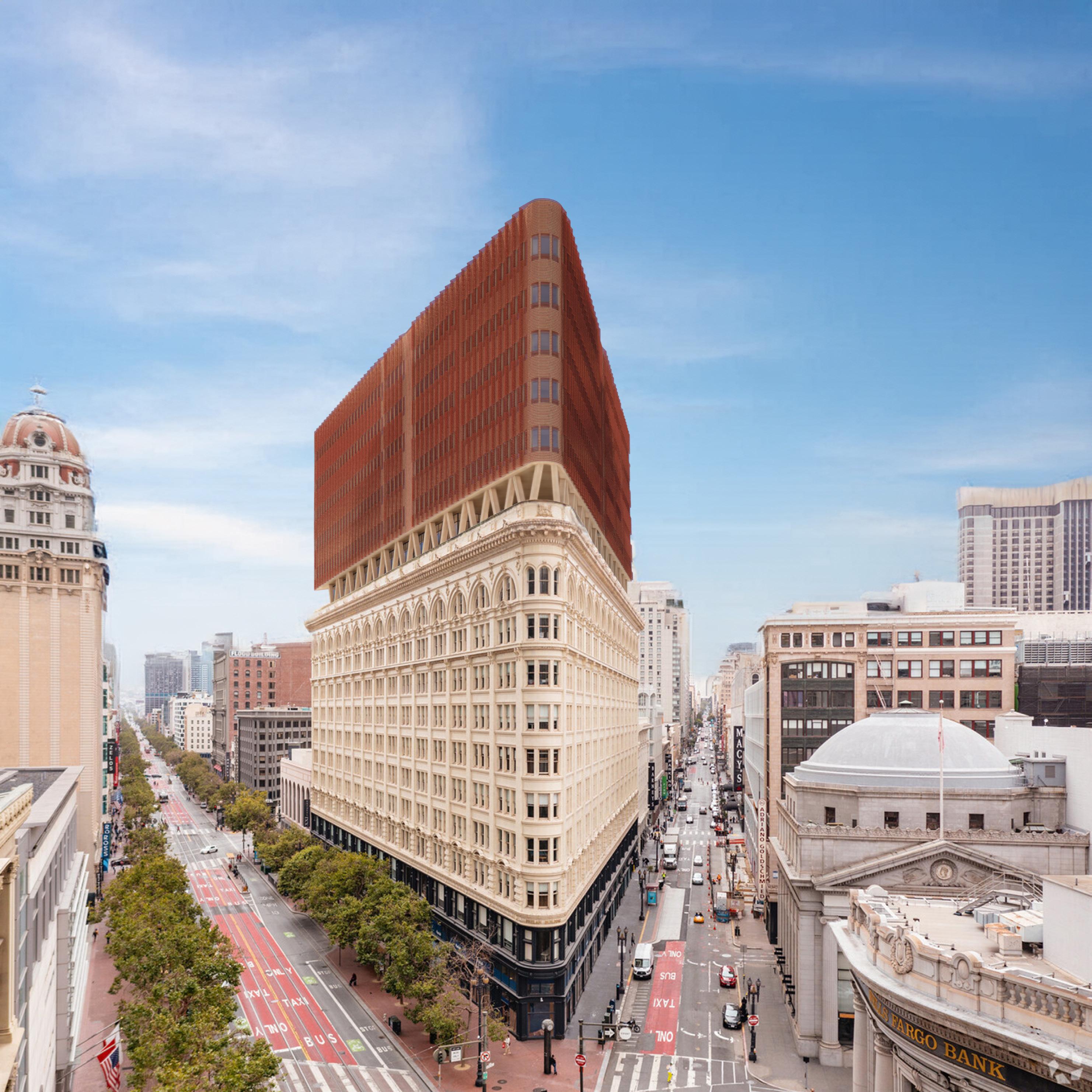
SOUTHEAST PERSPECTIVE

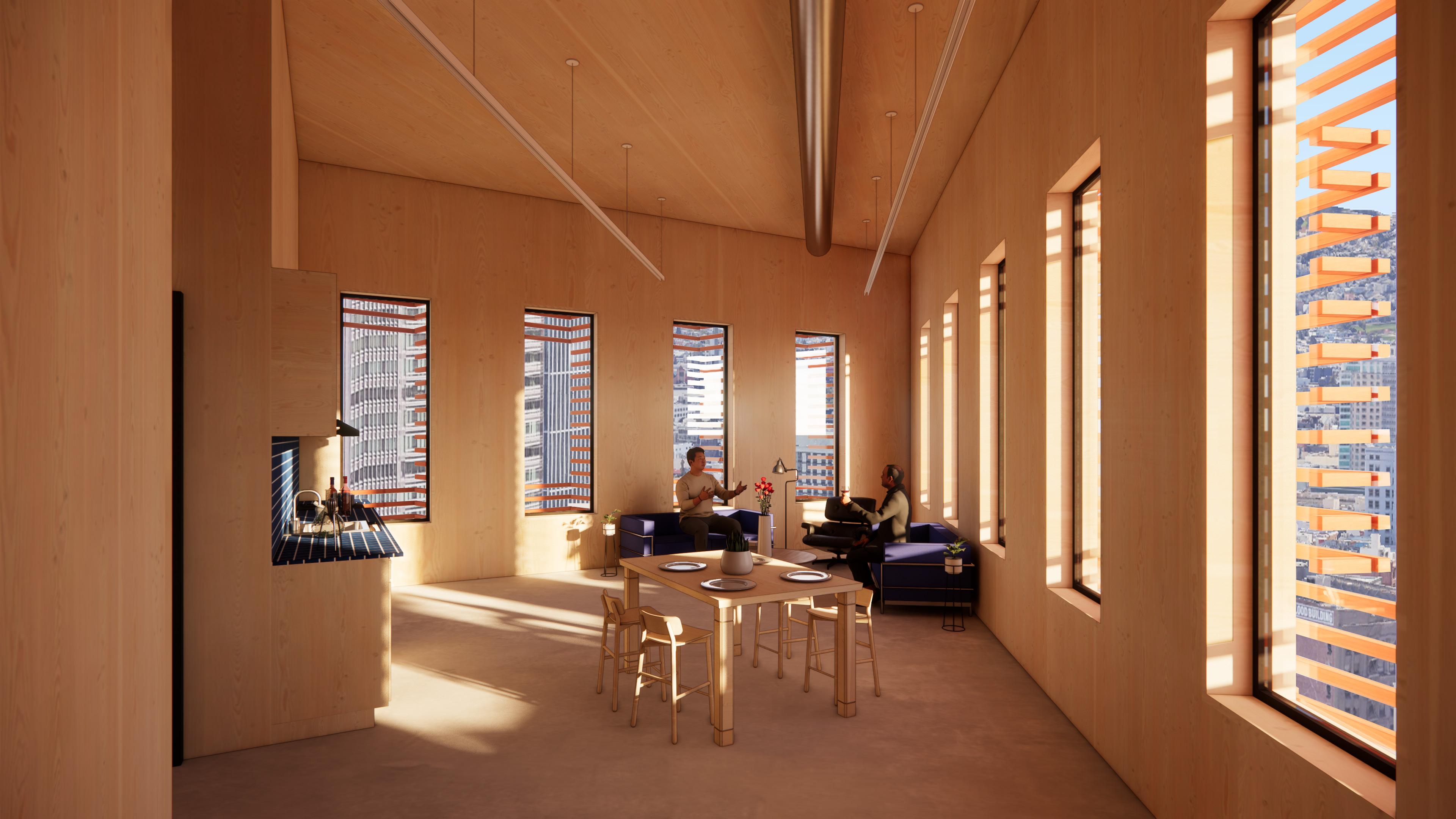
ONE BEDROOM CORNER UNIT
ONE BEDROOM CORNER UNIT