
Track and Field Stadium + Sports Performance Center

This stadium proposal is designed to house specifically track and field events. To serve the athletes, a sports performance center is a connected structure that houses program to support the athletes’ health and development. Using the dynamic movements and fluidity of track and field event partterns as inspiration, the structure translates the movement to a fabric. The ETFE roof begins to take on a weaving and pattern making inspired by tartan fabrics with their overlapping regularieites. This fabric is stretched over the metal structure of a compression ring and tied into the dramatic flanges as fabric is stretched over a loom. The horseshoe shape is present not only in the roof, but also the form of the building. The horseshoe shape keeps the building enclosed but also open. This results in a monolithic base that has a supporting enclosure but is still open to the outside.


Tsunami Evacuation Tower
Kalama Beach, Hawaii

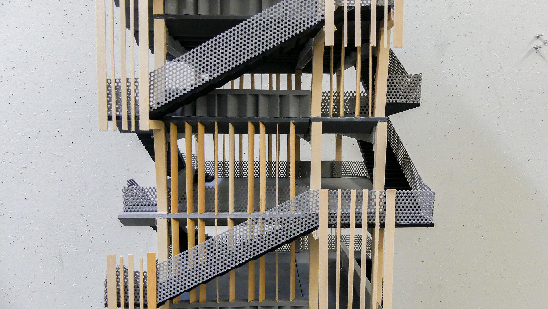
This tower is situated in a preservation zone in Kalama Beach in Kailua, Oahu. As one of three proposed evacuation towers in Hawaii, this project maintains the basic skeleton and pattern of the group’s base structure but elongates the building outline. The precast double tee has a wave-like shape, representing “Kailua” which translates to “two seas.” The local context of the Beach Club area and the enlargement of the floor plates allows for more people to inhabit the levels without needing to build up as high as the base tower. The facade came with a different approach, an oblique metal facade that took into account the datum lines from the stairs as well as the non-linear datums that came from the residential homes around. Overall the building’s porosity allows for ease of movement on the ground level and visual transparency to better fit a residential area.


Scientists’ Retreat
Vetter Mountain

This proposal for a scientists’ retreat and research center in Vetter Mountain is a shallow, reserved, shed-like structure placed on top of the mountain. The structure and typology of the building draws inspiration from the Yusuhara Wooden Bridge Museum. The building is organized around a core hallway and further divided based on a grid, making two distinct bars for the program to fill. The hallway creates the two halves - the side for work and the side for personal living spaces. The hallway links two decks with one being a public gathering deck accessible from a lower point of the site through a winding ramp that follows the contours of the topography, and the other a private observation deck accessible for the resident scientists. The activities in the buliding are balanced in its grid as the reserved building itself appears balanced on the mountain top.


Mixed Use Multi Family Residential Silver Lake, CA

This is the beginning of the design of a mixed use multi family residential project. The building is designed for 10 units of housing for artists, with plenty of open space for the residents to use as work spaces. The ground floor hosts a maker studio that the residents can showcase their work in while also being open to the public as a center for innovation. The buildng’s appearance is a series of individual rugged blocks which are carved out of larger original volumes. With this massing the building takes a village like typology to house the artists that live and work in this corner of Silver Lake.


 Left: Entry Render | Middle: Community Outdoor Space Render | Right: Bedroom View Render
Bedroom View Render
Graphic Design Work for CPP SIIL


Student Innovation Idea Labs
Website Design Logo Student Labs, Student Poly Pomona as 3D which and innovation called student spaces, This created the program the innovation showcased
Ceramics


