
Proceedings of the IASS Annual Symposium 2023 Integration of Design and Fabrication 10–14 July 2023, Melbourne, Australia
Y.M. Xie, J. Burry, T.U. Lee and J. Ma (eds.)

Proceedings of the IASS Annual Symposium 2023 Integration of Design and Fabrication 10–14 July 2023, Melbourne, Australia
Y.M. Xie, J. Burry, T.U. Lee and J. Ma (eds.)
Max G. MARSCHALL*, Jack WALKER, Daniel FITZMAURICE, Hamed SEIFI, Cindy LAM, Nathan PALEIRET, Darcy CREIGHTON, Qisi ZHENG, James ALLISON, Tristan MORGAN, Pablo SEPULVEDA, Matthew AUSTIN
*Aurecon
8/850 Collins Street, Docklands VIC 3006, AUSTRALIA Max.Marschall@aurecongroup.com
Abstract
A lot of the most consequential building design decisions are locked in during the early-design phase. However, lifecycle assessments are commonly conducted later in the planning phases where the analysis has limited potential to meaningfully affect the design. It would be ideal to front-load this analysis into the early-design phase, however, this is challenging since project information at this stage is limited and the design process is fast-paced. This paper addresses this challenge by creating a user-friendly webtool for indicative lifecycle assessments to be used during the concept design phase Existing research has resulted either in sophisticated software with maximised functionality but limited practicality for early design or point solutions that often lack the interdisciplinary approach necessary to achieve truly sustainable outcomes This tool is novel in that it addresses both embodied and operational emissions, and both the main structural and façade elements, while considering the margin of error associated with early-stage assessments and reaching carbon neutrality It does so as a web-based tool that provides integrated access to expertise through a highly accessible interface with near real-time feedback. A unique contribution of the tool is a design automation algorithm that auto-sizes structural members based on a first-principles approach.
Keywords: parametric design, user-friendly, lifecycle assessment, carbon neutrality, embodied carbon, operational carbon, agile development, energy modelling, environmental flows, concept design
Over the past decades, sustainable building design has focused mainly on operational emissions, that is, those associated with the day-to-day running of the building. With increasing progress on the energyefficiency of HVAC systems and high-performance facades, as well as the increasing decarbonisation of energy grids, the significance of embodied emissions associated with the manufacture and transport of building materials has risen. Sustainable building design should therefore consider lifecycle assessments (LCA). In other words, estimating both operational and embodied carbon emissions
Some of the most impactful building design decisions are made in the early project stages [1]-[3]. At this point, engineering analysis is commonly limited, while architects are left to make many design decisions based on tacit knowledge rather than data-driven insights It is difficult to significantly change the design after a town planning permit has been lodged, since this process solidifies design expectations with legal and financial ramifications should the initial design have to be reworked The issue here is that the town planning permit tends to lock in the structural system and overall envelope design, both of which are the greatest contributors to lifecycle emissions [4].
Copyright © 2023 by Max G. MARSCHALL, Jack WALKER, Daniel FITZMAURICE, Hamed SEIFI, Cindy LAM, Nathan PALEIRET, Darcy CREIGHTON, Qisi ZHENG, James ALLISON, Tristan MORGAN, Pablo SEPULVEDA, Matthew AUSTIN Published in the Proceedings of the IASS Annual Symposium 2023 with permission.
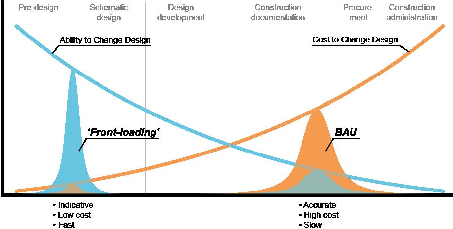
Figure 1. A “MacLeamey” curve as it applies to LCAs. (Adapted from [5])
LCAs are commonly only conducted in the late planning phases. This is a problem as design changes become increasingly costly as the project proceeds, hence the analyses have limited potential to meaningfully affect the design (Figure 1). Sustainable building design could be facilitated by ‘frontloading’ LCAs into the early design phase, but this is challenging since project information at this stage is limited and the design process iterative and fast-paced. This is a common dilemma that plagues all aspects of early design and is one that computational designers typically seek to alleviate by developing algorithms to automate processes and decrease the effort needed to conduct analyses, or by using new types of tools and visualisation techniques to enhance design processes, or sometimes even by developing custom software. Compared to other contexts, conducting LCAs for buildings is more challenging due to the long lifespans of buildings, their complexity, and the multiplicity of stakeholders involved throughout their design and operation [6] Any effort to conduct these kinds of analyses in the early-design stage must be accompanied by an understanding that the results will necessarily be indicative rather than accurate calculations These intrinsic error margins should not become a roadblock to considering sustainable design from the project outset; the uncertainties just need to be expressed clearly and quantified where possible [7]
While several academics have proposed various theoretical frameworks (e.g., [8], [9]) to tackle the challenges in conducting early design LCAs, there are now also numerous consultancies that have developed digital tools for use in practice. This is an emerging field with direct potential impacts on the sector with the largest contribution to worldwide emissions [4] and therefore warrants deeper research attention An analysis of the currently available tools shows a diversity in terms of the approaches and methodologies followed, the types of user input they require, the scope of carbon-related design tasks and disciplines considered, and the solution maturity. A lot of the existing tools appear to be in the beta phase of their development (e.g., [10]-[13]) which demonstrates that this is an emerging field in the industry. Some tools are specifically intended for browsing existing material emissions databases and therefore require an existing geometry model (e.g., [10], [12], [14], [15]), while others allow the user to input top-level geometric data (e.g., building width and length, etc.) and the tool then auto-sizes all building elements to estimate material volumes (e.g., [11], [13], [16]-[20]). Tools tend to focus on a specific discipline, typically producing an informed estimate either of the embodied carbon of the structure or the façade; a search conducted by the authors did not reveal an early design tool within this space that considered operational carbon There appears to be a gap in research to create a tool that:
• Holistically estimates emissions across all major contributors
• Assesses embodied carbon of the structure and façade as well as operational carbon
• Auto-sizes structural elements in the early design stage where a sophisticated geometric model (e.g., a reliable Revit model) may not be available for determining material quantities
• Allows exploring the interdependencies between upfront façade emissions versus lifecycle emissions through operational energy consumption
2.1 Aim
The aim of this research was to create a user-friendly design tool for conducting indicative, early-design stage LCAs and allowing a broad user group to compare design options holistically, for the goal of reducing lifecycle emissions in building design A focus of this tool was to enable user groups beyond sustainability experts to make informed decisions and communicate these to clients, while establishing a technological framework that retained flexibility for individual domain specialists to maintain and update algorithms and calculations.
2.2 Requirements
To achieve their aim, the authors developed a webtool called Aurecon Buildings Carbon sketcher (ABCs). The name was chosen deliberately to indicate the specific intent for using it to design buildings rather than other asset types ‘Sketcher’ intends to signal to the user that it is aimed at producing indicative estimates in schematic design, thereby distinguishing itself from other tools that conduct specific calculations to determine accurate results for compliance purposes in the later stages
To fulfil the purposes of an early stage LCA tool, the authors gathered the following requirements from key stakeholders and domain experts within their home organisation to be addressed by the tool:
• Consider the ‘big-ticket items’ in terms of lifecycle emissions and reaching carbon neutrality that can be assessed with information levels available in early design. In other words, consider operational emissions from energy use as well as embodied emissions for the main structural and façade elements, but exclude items that are unknown in the early design stage and have a lesser impact on carbon emissions, like interior finishes and furniture
• Make the tool accessible for a wide stakeholder group by minimising dependencies and user knowledge of third-party software, and without requiring users to install specialist software environments on their local computer hardware.
• Build it in a modular way from several domain-specific modules that can be maintained over time by subject matter experts from different disciplines
• Design the tool in a way that caters to about 95% of Aurecon building projects in terms of allowable geometric complexity and building usages.
• Design the tool for a user group consisting of environmentally sustainable design (ESD) consultants, mechanical, structural, and façade engineers.
• Assume the user does not have a detailed geometric model when using the tool. That is, the tool should auto-size structural elements based on the overall building massing.
• Develop ways to communicate to the user that the estimates generated by the tool are indicative and convey a margin of error
In essence, the overarching requirement for the development of the tool was to enable interdisciplinary design exploration to generate holistic low emission strategies in the early building design stage.
Proceedings of the IASS Annual Symposium 2023 Integration of Design and Fabrication
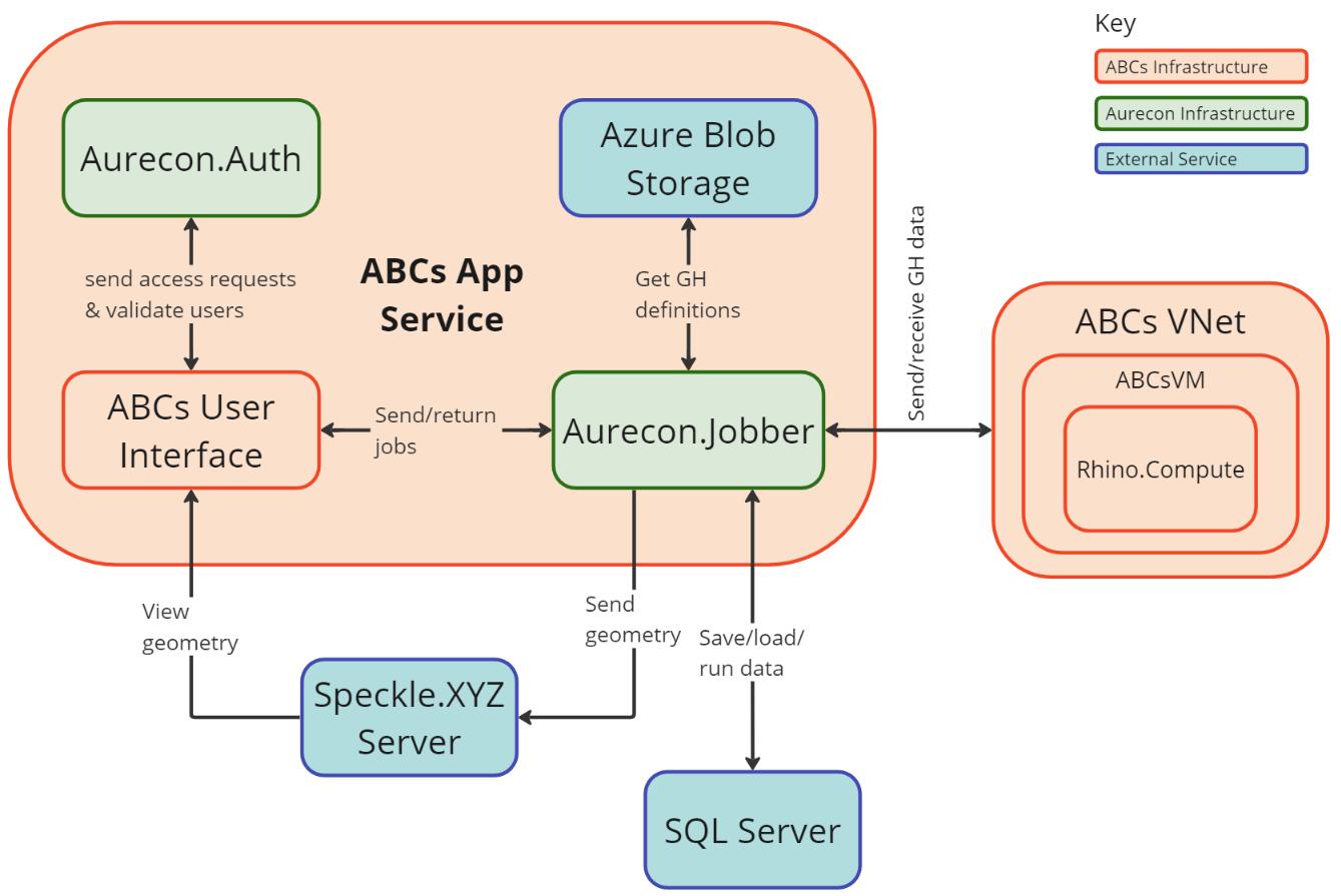
Figure 2. Overall software architecture and Grasshopper definitions contained within ABCs.

Figure 3. Developing, maintaining, and interacting with the tool. *See Figure 2
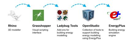
4. Software used for energy simulations.
ABCs consists of several Grasshopper definitions that run within Rhino.Compute. The definitions are provided inputs from a browser-based application built on the Blazor framework that uploads the results through a REST API hosted in the cloud. The Blazor application utilizes Speckle to provide the to the user an interactive 3D viewer with metadata. The Telerik for Blazor package is used to provide interactive web elements for the user to input design parameters, and to generate charts that the user can interact with to interrogate the results (Figure 2)
The development of ABCs was a joint effort between software engineers developing the “backend” of the tool, and domain experts creating calculation models (Figure 3). This includes a Grasshopper definition to create the building massing geometries (see Section 2.5), and one for applying the appropriate emissions factors to the corresponding building material and energy quantities (see Section 2.10). There are several domain-specific Grasshopper definitions that cover calculations relation to different disciplines impacting lifecycle emissions: structural element sizing (see Section 2.6), facade element sizing (see Section 2.7), energy modelling (see Section 2.8 and Figure 4), and on-site energy generation modelling (see Section 2.9). These Grasshopper definitions were created and are being maintained and extended by domain experts within the organisation who have appropriate computational design skillsets.
ABCs was designed to have a highly accessible and easy-to-use user interface and user experience (UI/UX), enabling a broad user group extending beyond computational designers, sustainability experts, and engineers. Rather than automating an existing process [21], the webtool proposes novel affordances that democratise and demystify the relationship between early-stage design decisions and emissions. In doing so, the webtool not only provides key insights to impact design, but also clearly illustrates relationships and sensitivities, supporting users to further develop their understanding of LCA and ESD.
During development, the authors conducted frequent demonstrations of ABCs’ UI/UX design to collect feedback from subject matter experts This helped design a highly accessible and easy-to-use tool. For example, the team discovered that one of the main roadblocks preventing from people using an earlier version of ABCs was that it had been built purely as a Grasshopper tool As a result, ABCs was built as a webtool that does not require any installations or specialised domain knowledge to use. It has a job management system in which the user can create ‘projects’; each project can have several ‘studies’, and each study can have several design ‘options’ to be compared in a dashboard view side-by-side (Figure 5) Clicking on a design option from a study page brings up the main UI (Figure 7)
The main UI consists of two columns: user inputs on the left and result visualisations on the right. The columns are sub-divided into logical sections that clearly differentiate between different disciplines; input sections including ‘Building’, ‘Structure’, ‘Façade’, ‘Shading’, ‘Materials’, and ‘Operation’, and output sections including ‘Geometry’, ‘Embodied Carbon’, ‘Operational Carbon’, and ‘Carbon Neutrality’. The interface does not freeze while waiting for simulation results to be produced; instead, the visualisation sections that are awaiting data are blurred out until the results become available while the user can keep navigating the UI. It includes an interactive Speckle 3D viewer displaying the structural, façade, and PV panel geometries.
The UI/UX was designed to convey the inherent uncertainties in early-stage LCA analysis. This was done by including a welcome page, guided tour, and documentation that describe the intent, assumptions, and limitations of the tool Result data is expressed in round numbers so as not to convey a false sense of accuracy [7]. As described in Section 2.10, embodied carbon is calculated using ‘high’, ‘medium’, and ‘low’ scenarios that are displayed side-by-side in the UI for the user to consider the variance of environmental impact across different materials.
Proceedings of the IASS Annual Symposium 2023 Integration of Design and Fabrication
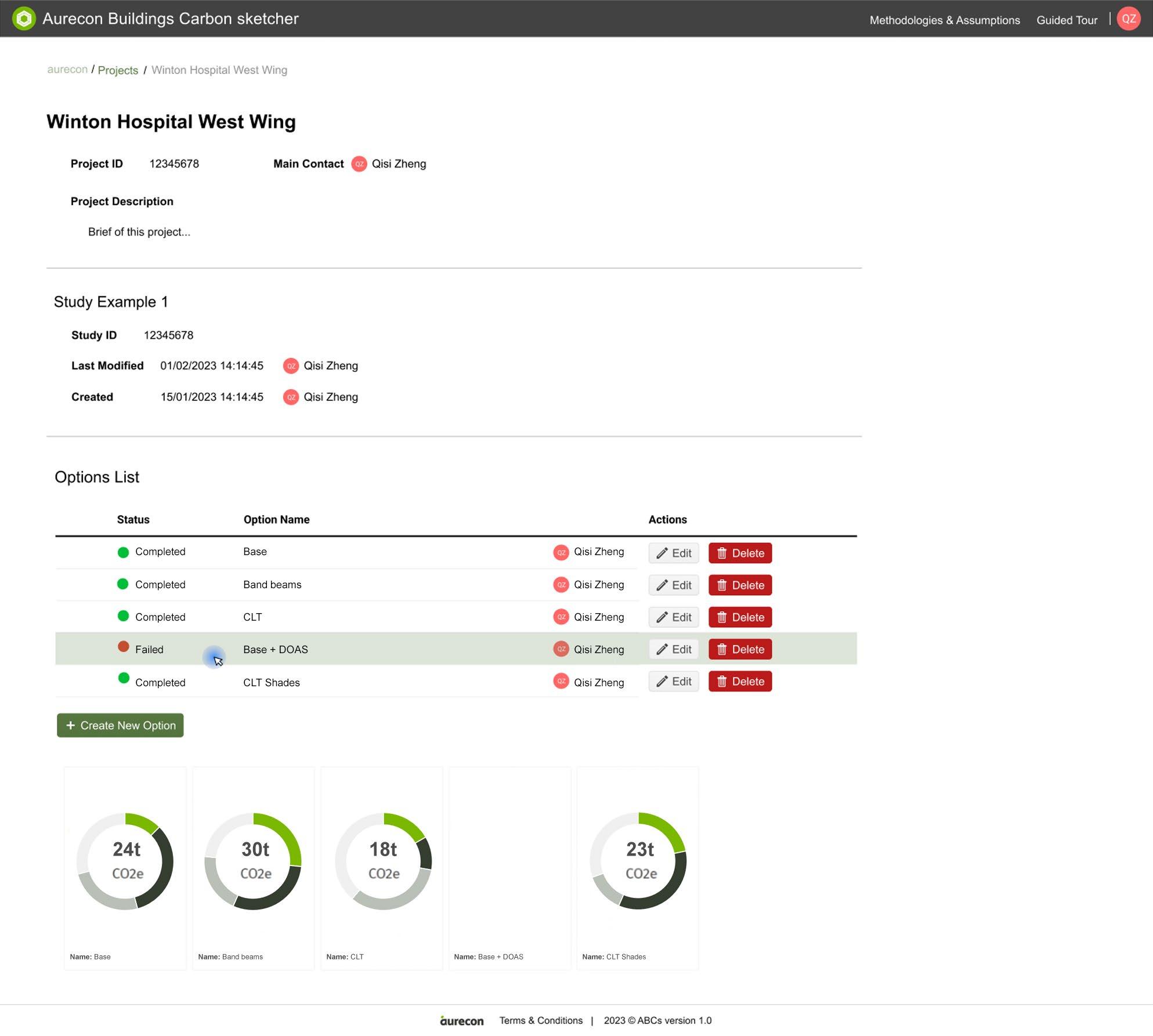

5 ABCs’ “Study” viewer to compare design options at a top level
2.5 Geometry definition
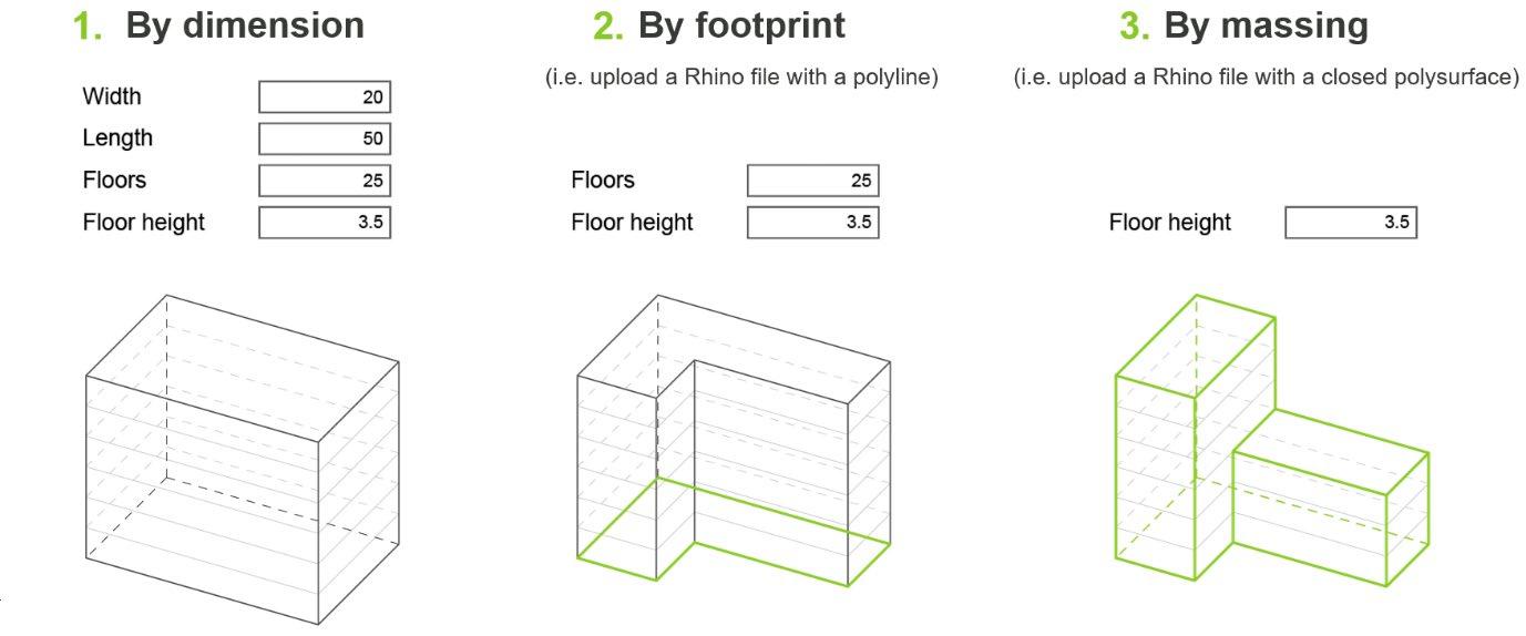
The first Grasshopper definition to execute within an ABCs run is one that generates the overall building massing as a closed polysurface. Users have three options to describe the building shape (Figure 6): for box-shaped buildings they can enter purely numeric parameters, for buildings that can be described as a vertical extrusion of an irregular footprint the user can upload a polyline defining the footprint, and for more complex building shapes they can directly upload a closed polysurface.
Proceedings of the IASS Annual Symposium 2023 Integration of Design and Fabrication
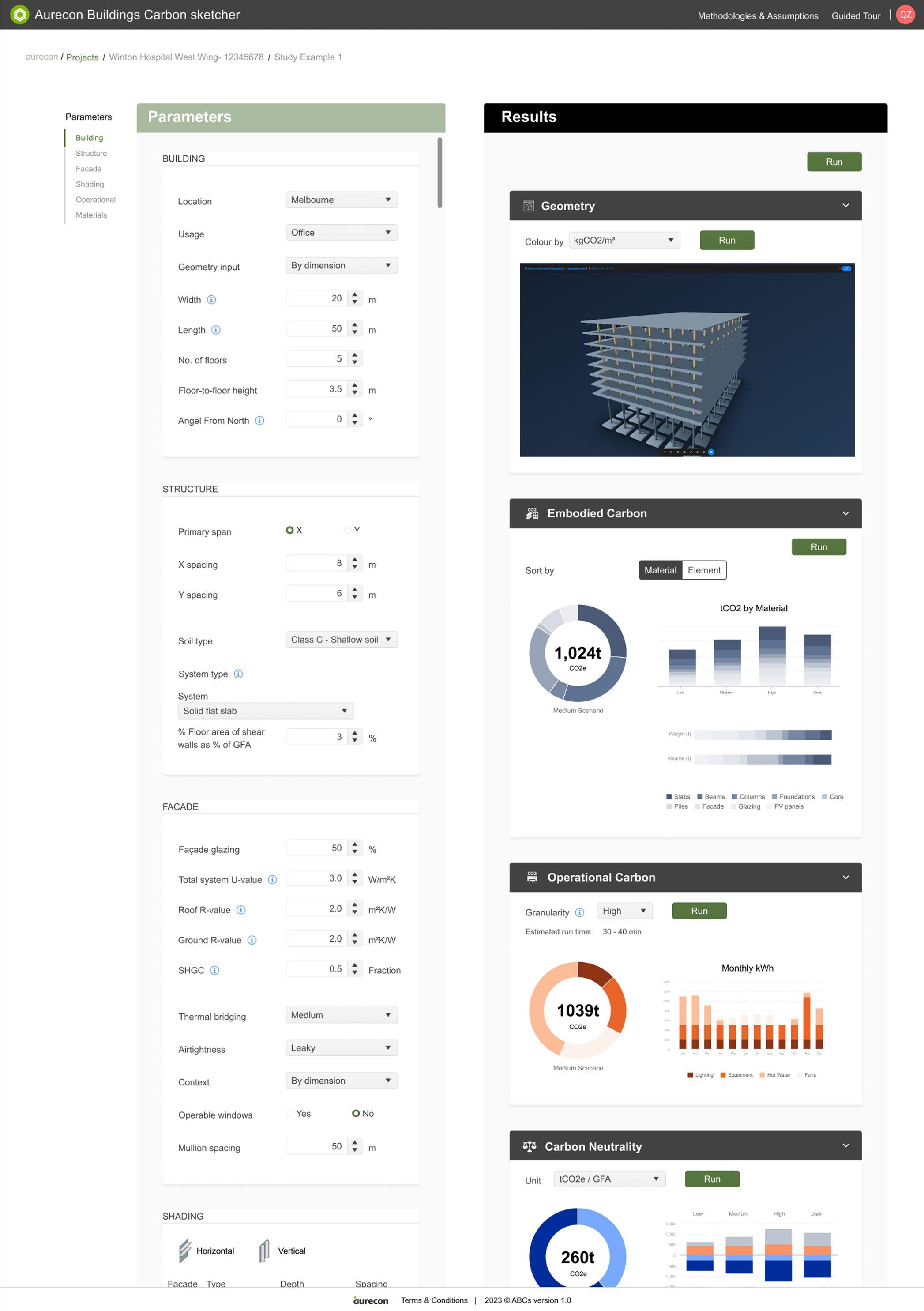

Figure 7. ABCs web UI. Each parameter panel reflects a Grasshopper definition executed with Rhino.Compute.
2.6 Structural definition
A particular contribution of the tool is a design automation definition that auto-sizes structural members based on a “first-principles” approach. That is, based on the building shape and user inputs it determines the applicable loads and slab thicknesses using basic formulas and look-up tables from various standards and supplier catalogues. Once the slab geometries are generated, it applies a similar approach to the beams, then the columns, and lastly the foundations and shear walls. The resulting geometries are sent to the Speckle viewer for visualisation in the web UI; the material quantities are sent to the Emissions definition (see Section 2.10) to calculate embodied carbon.
2.7 Façade definition
ABCs includes a simplified façade embodied carbon calculation that takes several user inputs to generate an estimate of various material volumes for a curtain wall façade (aluminium, glass, and rockwool) and sends these results to the Emissions definition The curtain wall framing elements are sized using preliminary wind load calculations following building Australian standards Mullions are sized assuming a simply supported condition, comparing the calculated deflection to an assumed deflection limit. To satisfy the resulting minimum required second moment of inertia (I-value), the definition selects a mullion and transom profile from a set of typical off-the-shelf products ABCs allows considering vertical and horizontal aluminium shading fins by allowing users to define their spacing and depth for each cardinal direction. All extrusions are assumed to have a wall thickness of 3 mm which is common for curtain wall façades The insulation, spandrel, and glass material volumes are calculated based on the user’s window-to-wall ratio and thermal performance input.
2.8 Energy definition
This definition runs an energy simulation using Ladybug Tools and EnergyPlus, and outputs the estimated annual operational energy consumption data to the Emissions definition (see Section 2.10). It also generates a wireframe of the façade to be visualised in the web UI.
The building mass is segmented into floors and thermal zones, band windows are applied (assuming a curtain wall façade), and shading elements are added as 2D surfaces based on the respective user inputs. User-defined thermal envelope properties are passed into the construction definitions. Thermal bridges are considered by applying a degradation of the thermal properties of these constructions as per the methodology used in the LBT2PH plug-in for Grasshopper. ABCs allows users to choose one of several building usages, based on which ABCs sets a default list of heat load assumptions. ABCs also allows users to pick from several HVAC templates. Finally, the user can pick a trade-off between accuracy and speed by means of a ‘granularity’ setting that modifies several of the simulation parameters and geometry creation processes (see Figure 8).
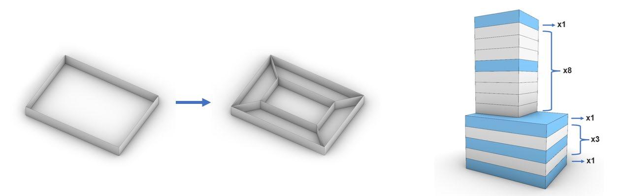
Figure 8. Examples of energy modelling simplifications. Left: ABCs allows either considering each floor as a single thermal zone, or as a core and several perimeter zones. Right: Only unique floors are considered
2.9 Photovoltaic definition
This definition isolates all roof surfaces, populates them with PV panels and runs a simplified calculation of energy generation using Ladybug Tools. It assumes common panel dimensions, tilt angles, spacings and capacities. The annual, cumulative incident solar radiation on the panels is determined using the Ladybug Tools, the results of which are scaled by an assumed panel efficiency to estimate energy generation. It sends the energy results to the Emissions script (see Section 2.10) and the PV panel geometries back to the web UI for visualisation in the geometry viewer.
2.10 Emissions definition
This script collects all material and energy consumption quantities calculated in the other definitions and applies carbon factors to estimate lifecycle emissions. Given the tool’s intent to be used in early design, the authors limited the tool’s scope to the lifecycle assessment (LCA) phases A1 (raw materials supply), A2 (transport), and A3 (manufacturing) for the embodied carbon calculation, and phase B6 (operational energy) for the operational carbon calculation. All units are given in weight (kg or t) of equivalent carbon dioxide (CO2e).
To give the user an idea of the variance in embodied carbon within different material types, the ABCs results section shows “High”, “Medium”, and “Low” scenarios. The corresponding embodied carbon values were determined by selecting representative products from various suppliers’ environmental product declarations (EPDs). To estimate the operational energy emissions, ABCs multiplies the annual energy outputs from the Energy definition (see Section 2.8) by the carbon intensity of the electrical grid of the region of the selected project location. ABCs considers the targets set by the governments of the different regions across Australia and New Zealand to decarbonise their grids by increasing renewable energy sources in future. While it is not guaranteed that these targets will be met, the authors deemed this scenario more suitable than assuming that the current energy mixes will not change in future, which would lead ABCs to convey the false impression that reducing embodied carbon has little impact over the building lifecycle. The purpose of ABCs is to generate insights by comparing options; not to conduct a precise LCA which would be impractical in early design.
The “Carbon Neutrality” section of the web UI simply shows the how much of the lifecycle emissions can be offset by on-site energy generation through PV panels, and therefore what the remaining difference is that would need to be offset by other means in order to reach carbon neutrality.
Our analysis led to several general insights and lessons learnt regarding the development of early-design lifecycle assessment tools. These are described in the following sub-sections.
3.1 Design strategy vs. design
The current use of lifecycle analysis in building design is limited to the late stages of the design process, where the results of the assessments have limited potential to meaningfully impact the design. Early design assessments have the potential to be much more valuable, however at this stage the design process is fast-paced and information limited. Adopting parametric modelling for lifecycle assessments in early design can create opportunities to explore design options more comprehensively and generate insights. Importantly, however, the designer must understand that the purpose of these design investigations cannot be to obtain a fully accurate and reliable prediction of actual lifecycle emissions. Instead, the value lies in generating insights that can inform an overall design strategy rather than a finalised solution.
3.3
Many current solutions for carbon reduction in building design are point solutions targeting a specific discipline. However, truly sustainable and low-carbon design tends to be the result of holistic design strategies and cross-disciplinary optimisation. Introducing a design feature that is low-carbon for one
discipline may cause a detriment to another discipline. For example, while introducing shading fins might reduce operational cooling energy emissions, these fins tend to be constructed from aluminium that is so high in embodied carbon that it might not pay off over the building lifecycle. Therefore, any tool developed to address this issue should consider a cross-disciplinary approach.
While the previous insight suggests increasing the complexity of a tool to address LCA in early design, there is an important trade-off that developers should consider: the usability and extensibility of the tool on the one hand, and on the other hand, attempting to optimise the tool’s accuracy by increasing the complexity of the tool’s parameters and calculations Through the development process of ABCs, the authors have found that the former often outweighs the latter. That is, it is recommended to focus on developing the tool to allow for interdisciplinary considerations and co-development, to produce a flexible tool that allows developing design strategies and creating insights, rather than hyper-focusing on a precision that is unrealistic to achieve given the nature of early design.
3.4
ABCs’ software architecture allows for a novel approach to maintenance, future development, and governance. Firstly, ABCs implements each discipline specific embodied-carbon definition as a standalone algorithm that obeys a designed schema. The advantage of this is that the platform becomes easily extendable with new models to produce increasingly accurate predictions as other disciplines develop strategies for calculating carbon. The extendibility of the platform can be achieved with minimal developer engagement meaning that extensions are not only easy to implement but allows for anyone with a low level of programming knowledge to contribute to the software. This becomes increasingly important as individuals with a high level of specific disciplinary knowledge do not always have highlevel programming experience. This allows for a simplicity in engaging and working with collaborators and maintain disciplinary definitions. Secondly, disciplinary specialists have a degree of ownership and responsibility over their contribution to the software platform. This includes changing and updating the model, maintenance, and testing for accuracy. The value of such a distinct set up is that the individuals with the knowledge to produce and check the outputs of the algorithms are the individuals producing the algorithm.
Thus, the governance and ownership of the tool allows for individual actors to contribute to carbon reduction in whatever way they can. Although the definitions produced to give carbon results for ABCs are not necessarily novel, the capacity to allow these disparate disciplinary definitions to conglomerate into a more inclusive and complete calculation is. Rather than having to engage a series of disciplines and depend upon their time and hardware, ABCs provides access to this expertise in a real-time, dynamic environment using modern web-development frameworks and remote computing to make this analysis as accessible as possible.
Reducing both up-front and operational emissions in the built environment has become increasingly crucial, as it accounts for a significant portion of global emissions. However, the industry faces a complex challenge due to a variety of factors. Firstly, operational emissions depend on local conditions, such as climate, site characteristics, and the emission intensity per kWh of the regional power grid. Secondly, in a global economy, the up-front emissions for the same material can vary greatly. Lastly, the technical and interdisciplinary expertise required to define a low-emission building can be overwhelming.
Without an interdisciplinary approach and a tool that considers the specificities of each project, it is difficult to develop a low-carbon strategy that properly considers the project context. By focusing on major carbon contributors and understanding the interdependencies between different fields, the tool
Proceedings of the IASS Annual Symposium 2023 Integration of Design and Fabrication
proposed by the authors within the current research aims to establish a solid foundation in the early design stage for low-emission buildings
The research led to several more general conclusions on developing early-design lifecycle assessment tools. For example, their purpose should likely be to inform a design strategy rather than a finalised design; developers should accept that the results will be indicative and design a user interface that illustrates margins of error. Most development decisions will be related to finding an acceptable tradeoff between flexibility and accuracy. Importantly, carbon footprint reduction is best tackled as an interdisciplinary design practice.
The authors seek to deepen the research in future by considering the following factors:
• Increase functionality and options: For example, include other façade and structural system types, and the embodied carbon of services.
• Revised carbon factors: Replace the current indicative carbon factors by ones based on an extensive data analysis of large LCA databases; also include other emissions metrics.
• Benchmarking: The ability to get an LCA “score” for a given design option (e.g., using [22])
• Cost: Considering the cost impact of different design features.
• Machine learning: ABCs logs all design options ever simulated by its users. Once a sizable database has been generated, the authors intend to use it to generate new insights and conduct predictive modelling to decrease simulation times
• Horizontal extension: The authors intend to create variations of tools like ABCs but geared toward other markets and asset types. The way that ABCs has been developed (see Section 2.3) specifically facilitates reuse and extension of this kind
[1] E. O. Cofaigh, E. Fitzgerald, R. Alcock, A. McNicholl, V. Peltonen, A. Marucco, A green Vitruvius: principles and practice of sustainable architectural design London: James & James (Science Publishers) Ltd, 1999.
[2] P. Ellis, P. Torcellini, D. Crawley, “Energy design plugin: an EnergyPlus plugin for sketchup,” Berkeley: IBPSA-USA SimBuild Conference; 2008.
[3] S. Kotaji, A. Schuurmans, S. Edwards, “Life-cycle assessment in building and construction: a stateof-the-art report of SETAC-Europe.” Brussels: Society of Environmental Toxicology & Chemist; 2003
[4] T. Abergel, B. Dean, and J. Dulac, “Towards a zero-emission, efficient, and resilient buildings and construction sector: Global Status Report 2017,” UN Environment and International Energy Agency: Paris, France, 22.
[5] D. Davis. “MacLeamey.” Daniel Davis. https://www.danieldavis.com/macleamy/ (accessed April 14, 2023)
[6] M. M. Khasreen, P. Monkiz, P. F. G. Banfill, and G. F. Menzies, "Life-Cycle Assessment and the Environmental Impact of Buildings: A Review" Sustainability 1, no. 3: 674-701, 2009.
[7] A. Hollberg et al., “Review of visualising LCA results in the design process of buildings,” Building and Environment, vol. 190, March 2021.
[8] F. Shadram and J. Mukkavaara. "An integrated BIM-based framework for the optimization of the trade-off between embodied and operational energy." Energy and Buildings 158 (2018): 11891205.
Proceedings of the IASS Annual Symposium 2023 Integration of Design and Fabrication
[9] J. Basbagill et al. "Application of life-cycle assessment to early stage building design for reduced embodied environmental impacts." Building and Environment 60 (2013): 81-92.
[10] Arup. “A Carbon Tool.” https://act.speckle.arup.com/assessment (accessed April 14, 2023)
[11] Sasaki. “Carbon Conscience.” https://carbon-conscience.web.app/ (accessed April 14, 2023)
[12] Building Transparency. “tallyCAT beta ” https://www.buildingtransparency.org/tally/tallycat/ (accessed April 14, 2023)
[13] Bollinger+Grohmann. “B+G Structural Web Tool beta.” https://structural-webapp.vercel.app/ (accessed April 14, 2023)
[14] Thornton Tomasetti. “Beacon ” https://www.thorntontomasetti.com/capability/beacon (accessed April 14, 2023)
[15] One Click LCA. “Calculate your environmental impacts in minutes.” One Click LCA. https://www.oneclicklca.com/ (accessed April 14, 2023)
[16] Ramboll. “Fenix tuo rakennesuunnittelun tulevaisuuden tähän päivään.” Ramboll https://c.ramboll.com/fi/fenix-by-ramboll (accessed April 14, 2023)
[17] Thornton Tomasetti. “Asterisk*.” Asterisk alpha. https://asterisk.thorntontomasetti.com/ (accessed April 14, 2023)
[18] J. Helal, “Towards a comprehensive framework for integrating embodied environmental flow assessment into the structural design of tall buildings,” Ph.D. dissertation, The University of Melbourne, Melbourne, VIC, Australia, 2021.
[19] Akt II. “Carbon.AKT.” akt II. https://www.akt-uk.com/latest/akt-carbon-calculator/ (accessed April 14, 2023)
[20] Payette. “Kaleidoscope: Embodied Carbon Design Tool.” https://www.payette.com/kaleidoscope/ (accessed April 14, 2023)
[21] R. E. Susskind and D Susskind, “The Future of the Professions: How Technology Will Transform the Work of Human Experts”. Oxford University Press, 2017, p. 111.
[22] K. Simonen, R. R. Droguett, L. Strain, and E. McDade, “Embodied carbon benchmark study: LCA for low carbon construction”. University of Washington 2017