



























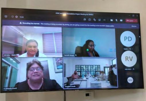
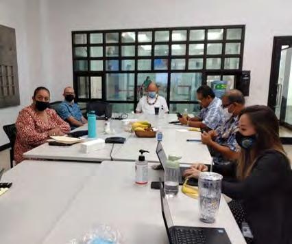
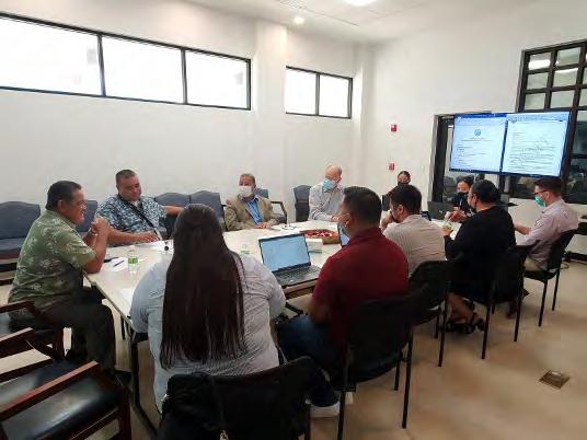
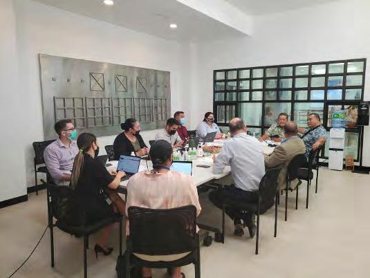





THEEDITORIALBOARD





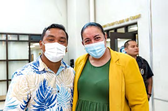
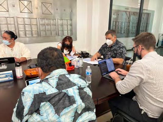
The data and information contained in this HVAC Report was compiled and edited by an Editorial Board comprised of Judiciary Administrative Office leadership, Office of General Counsel, and Supreme Court staff. Many thanks for their diligence and dedication throughout the duration of the HVAC and mold remediation project and for their continued involvement in the next phase of this project--the Fire

System.
 Alarm and Sprinkler
SoniaA.Camacho DirectorofCourts
HyunJaeLee GemeralCounsel
JohnT.Villagomez BudgetandFinanceDirector
MarthaM.Standish ARPAAdministrator
MatthewJ.Brown DeputyGeneralCounsel
MaryBernadetteC.Glass Paralegal
KeithH.Ketola LawClerkto JusticeJohnA.Manglona
September 2022 HVAC Report 133
�� JosephineN.Estrada JudicialAssistantto JusticeJohnA.Manglona





PAYABLES
PAYABLES: $1,055,197.14
62
PURCHASE ORDER NO. VENDOR SCOPE OF WORK OUTSTANDING AMOUNT 678804-00 OP M.S. Villagomez Temporary storagespace for court files $3,600.00 677056-00 OP IT&E Hoisted VOIPLine and Labor and cabling $7,653.80 CONTRACTOR CONTRACT NO. INVOICE NO. DATE DUE OUTSTANDING AMOUNT DESCRIPTION WMES 672803-OC WM18-218-15 9/15/21 $10,230.16 POST AWARD SERVICE WMES 672803-OC WM18-218-15 9/15/21 $1,164.76 TRAVEL EXPENSES WMES 672803-OC WM18-218-16A 9/15/21 $6,885.74 POST AWARD SERVICES WMES 672803-OC WM18-218-16A 9/15/21 $1,716.10 TRAVEL EXPENSES WMES 672803-OC WM18-218-15A 4/4/22 $1,261.00 WINDOW A&E WMES 723906-OC WM18-218-20 2/8/22 $1,445.88 POST AWARD SERVICE WMES 723906-OC WM18-218-21 2/8/22 $1,496.72 POST AWARD SERVICE WMES 723906-OC WM18-218022 2/8/22 $2,503.52 POST AWARD SERVICE CHONG'S 698294-OC APPLICATION PAYMENT NO. 11 1/30/22 $398,686.23 APPLICATION PAYMENT NO. 11 CHONG'S 698294-OC APPLICATION PAYMENT NO. 12 1/30/22 $501,193.23 APPLICATION PAYMENT NO. 12 J&J COMPANY 710600-OC INVOICE NO. 0500121 5/10/21 $41,040.00 PURCHASE AND INSTALL FLOOR TILE (RM. 217, & 223) HBR INTERNATIONAL INC. 32200775 B22-0060 5/13/22 $76,320.00 REPAIR OF DAMAGED AND/OR DETERIORATED CONCRETE WALLS AND TRIMS
September 2022 HVAC Report | 63
HVAC FUND STATUS
64 CONTRACTOR PO/CONTRACT NO. AMOUNT ALLIED PACIFIC ENVIRONMENTAL CONSULTING 665208 $9,978.75 SAIPAN TRIBUNE 666552 $675.00 JWS 667074 $750.00 WAKI'S CARPET CLEANING 672847 $735.00 WAKI'S CARPET CLEANING 672848 $352.00 FRITZ PACIFIC 669010 $8,952.00 HAO'S AIRCONDITIONING 668477 $4,800.00 JWS 671842 $69,736.00 MECHILLE CORPORATION 672681 $2,730.00 CUC 674320 $365.00 WHITE COCONUT 674532 $5,977.00 SAIPAN TRIBUNE 676974 $995.00 IT&E 677056 $7,653.80 KOA CONSULTING, LLC 677516 $8,748.86 MSV 678804 $9,600.00 COMMONWEALTH UTILITIES CORPORATION $485.00 ADVANCE CARRIER 678439 $2,568.00 ROYAL PACIFIC EXPRESS 715033 $3,500.00 CTSI LOGISTICS SAIPAN 714808 $5,650.00 MSV, INC. 702079 $4,800.00 MECHILLE CORPORATION 724194 $9,276.92
September 2022 HVAC Report | 64
RECEIVED: $7,000,000.00
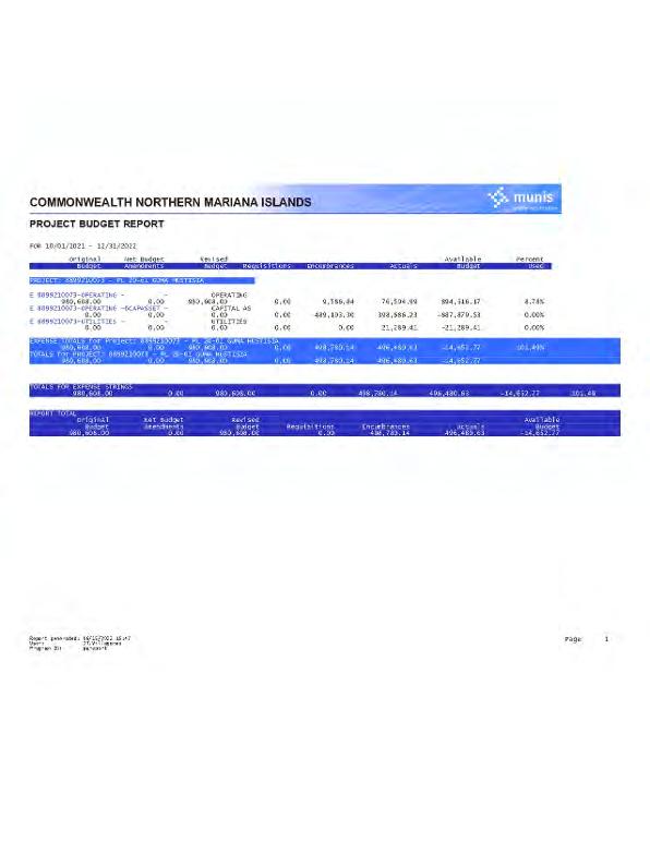
Exhibit A Miller's Preliminary Report
70

Assessment for Mold Remediation and Eradication Design at the Guam Hustisia, Iimwal Aweewe, House of Justice Susupe, Saipan CNMI Preliminary Report February 19, 2018 SUBMITTED BY: P.O. Box 392, Hagåtña, Guam 96932 Tel.: (671) 646-8127 Fax: (671) 646-0704 E-mail: main@wmesguam.com 71
I. EXECUTIVE SUMMARY
This report covers the examination of the mold issue that has plagued the House of Justice as it relates to the air-conditioning system in place. A four-day survey was conducted from 29th of January to 1st of February 1, 2018. The survey covered a visual inspection to the facility, interviewing of building personnel in familiar with maintenance and operation of the air conditioning system in place, installing data loggers through the facility and equipment to record dry bulb temperature and relative humidity reading while the building was in use and when the building was unoccupied. Data was also collected on the air flow at the various zones, measuring the air flows of ceiling diffusers and registers for supply air, return air, and exhaust air. Data was used to analyze the dynamics of the air conditioning in place and how it affects the mold issues in the building.
What was found in the data and information gathered data shows that the building indoor condition promotes the growth of mold spores and colonize in surfaces. The mold and mildew within the building are evident by the musty smell throughout the facility It was most likely caused by water leaks from a various incident that happens in the building over the years During the inspection, there were only a few visible signs of mold on books, furniture, judge’s robe, and ceiling tiles, but none within the air handling units (AHU’s) and within the ductwork. The musty smell appears to be generated by materials that remained after the water leak events and not properly remediated to prevent the potential of mold growth such as carpet, furniture, ceiling tiles, gypsum board walls, furniture, books, papers, etc.
The air conditioning system does play a part in the continued problem of the musty smell by its inability to properly control the relative humidity within the various zones. Because of the changes in the uses of spaces throughout the building, the cooling load requirements have changed significantly, and the existing units are overcooled causing the room temperature requirements to be met quickly and not allowing enough time for the dehumidification process to occur thus causing wet-cold air. Additionally, there is very poor indoor air quality within the building. Most of the outdoor air dampers at the AHU’s were shut and inoperable. Also, almost all the exhaust fans were not working. This leaves the musty smelly air to re-circulate within the building with little means of escape.
72
Except for an ARRA funded chiller replacement in 2008 which installed new chiller, remote condenser and pump, most of the air conditioning system is old and antiquated with most equipment being what was originally installed when the building was open in 1997. Two of the existing chillers are still utilizing the R-22 refrigerant scheduled to be phased out in 2020. It is recommended to remove and replace older equipment and upgrade the system more appropriate to the current use of the building while improving the indoor air quality of the building.
73
II. GENERAL
WM Engineering Services, LLC (WMES) was tasked to provide mechanical consultation services to assess mold and high humidity throughout Guma’ Hustisia, Iimwal Aweewe, House of Justice Building located in the village of Susupe, Saipan, Commonwealth of the Northern Mariana Islands (CNMI) that may be caused by the existing air-conditioning system in place. The assessment shall focus on the air-conditioning system components including all associated equipment, piping, and controls. The intent of this project is to assess the current condition of the air-conditioning system that may be contributing to the high humidity conditions and mold, develop a concept design for the scope of work for the corrective repairs to the air-conditioning and ventilation system. The existing building is a concrete structure constructed in 1997 consisting of a basement, ground floor, and second floor, and houses the Supreme Court, 5 Superior Courtrooms, Justice and Judges Chambers, as well as supporting offices, library, and utility areas totaling to 32,637 square feet. Based on the construction documents provided, the airconditioning system in place is an air-cooled chilled water system which distributes chilled water at a constant volume to various air handling units and fan coil units. The air handling units and fan coil units are constant volume ducted systems which deliver cool air to the various cooling zones within the building. The controls for the air conditioning system are all local to the equipment and are stand alone. There is no central building automation system that controls or monitors the chiller plant, pumps, air handling units, fan coil units and exhaust fans.
WM Engineering Services conducted kick-off meeting on January 29, 2018, at 09:00 with the stakeholders involved with the maintenance and operation of the existing system to discuss the project concerns, challenges, goals, and expectations. WM Engineering Services then proceeded with a field survey immediately after the meeting. The survey was conducted from January 29 to February 1, 2018, on the existing air-conditioning system in place at the Judiciary Building. The survey included the verification of as-built conditions of the air conditioning systems in place by:
• taking photos to document of the facility
• record existing air flow at the registers throughout the building
74
• record temperatures, and relative humidity of various spaces
• confirm the operation and performance of air conditioning and ventilation equipment
• visually identify areas of suspicious mold growth and high humidity.
It should be noted that this investigation will not involve any breaking of walls, floors, and ceilings and will be limited to areas readily accessible and visible including access panels available. It should be noted that mold remediation and humidity solutions may extend beyond just the air-conditioning and ventilation system and may also include other disciplines such as architectural, industrial hygienist, and electrical engineering disciplines which are not part of this contract Our proposal excludes such architectural, industrial hygienist, mold spore evaluation, and engineering services.
75
III. FINDINGS
Since the facility was first built and occupied in 1997, there has been no significant changes recorded to the air conditioning system except for the “addition” of an ARRA funded 200 TON Smardt Chiller in 2008-2009 that included a new air-cooled condenser and chilled water pump. According to the building staff the building has been experiencing elevated relative humidity and mold issue over the past 10 years. Over the years there have been several changes of Building Superintendents supervising the facility. With the change of personnel, there appears to be a poor turnover of record keeping of the building’s maintenance records. Presently there are no available maintenance records or OperatingMaintenance manuals for the existing equipment. The current Building Superintendent stated there is no current preventative maintenance program in place for the air conditioning and ventilation system due to funding issues and the repairs and maintenance are on an on-call basis as required. On the kick-off meeting, it has been discussed the event of major water damage from a pipe bursting where the lower floor was flooded with kneedeep water in early 2000, but the remediation and repairs to the building appear undocumented. There has also been water infiltration damage from the Soudelor Typhoon. There is a contract in place to re-seal the windows which are continuing to leak wind-driven rain into the building. There is also an on-going contract to replace all carpet in the facility with laminate vinyl floor tiles.
It was found that there were several undocumented changes in room partitioning and changes in room use which differs from the construction document plans on record. A lot of designated offices have become the storage room for files, and other miscellaneous office supplies and furniture. Another major change to the building was the enclosure of the public lobby of the House of Justice building and the addition of a large package air conditioning unit, although the unit is not currently in operation. This area was originally designed as an open-air area with natural ventilation. Another significant change in use is the Library which currently used for offices, assembly, and file storage.
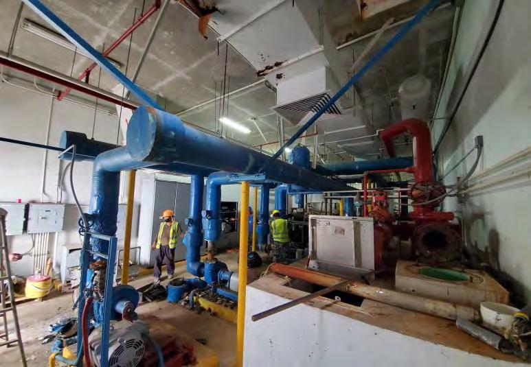
The water side of the HVAC system consists of two (2) 100-TON air cooled chillers, one (1) 200-TON Smardt chiller and three remote air-cooled condensers. The current system operates with the Smart DT chiller operating as the primary chiller in operation with the
76
two TRANE chillers as back-up. The Smart DT chiller utilizes R134a refrigerant and the TRANE chillers both are R-22 type refrigerant. During the survey, the Smart DT Chiller was down for repairs and the two TRANE chillers were operating but only at 50% each due to compressor or refrigerant circuit issues on each chiller. The existing remote aircooled condensers were on the roof but were not accessed. The current leaving chilled water temperature conditions at 52 degrees F and returning at 56 degrees F, See appendix photo 1.0
Based on existing plans the chilled water pump is end-suction pumps rate at 240 gallons per minute (GPM), 120 feet total dynamic head pressure, and 25 horsepower. Currently, the newly installed chilled water pump number three (3) is down for repairs. Pump gages are not calibrated or broken so pump pressures could not be confirmed. The remaining 2 older pumps appear to be in fair condition, and the pump base and foundation are in fair condition. Originally the chilled water pumps were interlocked to operate with its associated chiller but appear to be manually operated. The indoor chilled water piping and insulation remained intact. Chilled water components are in fair conditions, but the surface of piping showed signs of corrosion, see photo 1.1.
Due to Scope of work, there was no testing of the valve and inspecting inside section of each component. More so, the underground chilled water pipe is not assessed. There is a suspected water leak in the chilled water piping system which requires the make-up water tank to be filled every 3 days according to maintenance sub-contractor JWS.
The air side of HVAC system consists of chilled water type Air Handling unit and Fan Coil units which distributes air into the various rooms within its respective zone via an insulated steel duct system. There are 16 large AHU ranging in capacity of 10 TON to 25 TONS of cooling. The smaller FCU consist of 8 units and range from 1 TON to 2.5 TONS of cooling. The AHU’s are single zoned, constant volume unit and have a mixing-filter box with washable filter. There was originally motorize dampers on the outside air and return duct, but they are not operational. The original automated controls have been disabled and the AHU’s are being controlled locally by a temperature sensor in the main return duct within the mechanical room and a thermostat controller on the mechanical room wall. There is also a timer installed within the mechanical room but was disabled for the most part. There is also a large TRANE package type unit, independent of the chilled water
77
system, located on the supreme court roof and intended to cool the main entry but the capacity could not be confirmed because it is missing the nameplate data. This unit is currently not operational, and it is not known if it is still functional. The Building Superintendent stated it was not in use to reduce electric cost. There is a standalone direct expansion unit located in the ADR/Conference room area. A separate split type unit in the IT room that supplements the existing air supply near the former storage/workroom. There are three (3) 120-pint Honeywell dehumidifier was added and installed in the return duct of AHU 8, 14, and 15 that are in constant operation, but there are no plans or other design documents recording what was installed or how it was installed. The installing contractor JWS did mention that the dehumidifiers are always in operation, but it was not clear how it’s operation coincides with the operation of the AHU’s.
Air Handling Unit (AHU) Number Area Served 1. Superior Court 202 2. Superior Court 205 3. Superior Court Administration 4. Superior Court 217 5. Superior Court 220 6. Superior Court 223 7. Superior Court Administration 8. LRC / Library 9. Probation, Accounting, and Marshal office 10. Press 11. Commonwealth Recorder 12. Superior Clerk of Court 13. Supreme Clerk of Court 14. Supreme Court Administration 78
Table 1.1 Equipment number and the area it serves.
15.
16.
17.
PCU-1
Supreme Court
Sally Port/Basement
ADR/Conference Room (DX-split Unit)
Main Entry (Package Unit)
The AHU # 2 filter and filter rack were severely damaged due to corrosion, see photo 2.8. The AHU that serve the Superior Courts 202, 205, 217, 220 and 223 each has outside air damper that was shut closed and corrosion damage is present on each damper’s louver, see photo 2.9. The AHU # 3, 7, 9, 11 and 12 are installed with new outside air Manual volume damper and was also close The old actuator motor and its wiring are left inside the Mechanical Room, see photo 3.7. The AHU # 10 is installed above the ceiling of Evidence Room at Marshals Office. Unit’s Power and control wiring are pulled out of its connection. Smaller FCU was not visually surveyed because they were primarily recirculation of air within small spaces. Ductwork within the mechanical room appeared to be in fair condition except for the outside air ducts and some mixing boxes which were corroded and inoperable. Accumulation of dust and dirt are present at diffuser face and at intake louvers.
See photo 5.1.
The only air circulation comes from the people traffic which comes mostly in the main entry for the public and the employee traffic in the back entry. This allows untreated warm humid air to enter the building without being treated. There are several exhaust fans and ventilators throughout the facility and most are not operational. Many of the exhaust registers are cover with dust. The controls appear to be either manual controls or interlocked with the light switch.
IV. ANALYSIS
There was a strong musty smell within the air-conditioned areas which is a sign of an environment that promotes mold and mildew. Mold and mildew usually can be found in building components (duct insulation, gypsum board, ceiling tiles wood, etc.), furniture, papers, and carpet floor covering where water is absorbed readily. The usual cause would be water damage from water leaks from piping or water infiltration into the building from wind-driven rain such as a storm or typhoon or even structural cracks on the roof or
79
improperly sealed pipe, or duct penetrations through the walls or roof. Once the mold and mildew have occurred within the building, the best way to remediate is to remove the affected areas and maintain a dry environment. Because there has been recorded major water damage from a pipe leak and continues to have water leaks around the window, the presence of the mold and mildew will persist until physically removed from the premises. Disinfecting and cleaning of affected areas can remove on the surface but will not remove mold and mildew deep inside the material. The planned removal of the carpet and the repairs to the leaky window are a good way of reducing the sources of moisture that promote the growth of mold and mildew in the building. It is strongly recommended to dispose of all clothing in one of Justice’s wardrobe closet, furniture, books, and papers where mold is visible, see photo 5.6. There were only a few areas where building components had visible mold and mildew. No visible mold on the surface of walls and partitions. Some were found on ceiling tiles such as in Jury Room C, but they appear to be water leaks from the structure Many ceiling tiles on the first floor and second were sagging and could be an indication of high water content in the material, thus ceiling tiles should be replaced, see photo 5.2. There was no evidence of mold and mildew within the cooling coils, air filters, fans, or inside the ducts. It is highly recommended that the air distribution ductwork, air handling units, fan coil units, and diffusers/registers be professionally cleaned. Also, install more efficient disposable MERV 13 filters in the AHU’s and FCU’s to reduce the dust in the building. The fungus is more likely to grow whenever the environment suited them. A spore (seed), a viable source of food, adequate moisture in the food source and acceptable temperature are the four (4) elements that molds needed to grow. Over the years, the building where exposed to several types of water damage. Without a proper water removal or drying, moisture remains entrapped in the surfaces. Introducing cool-dry fresh air into the space help help lower the humidity level in the space. With the lack of fresh air due to the closed fresh air intake dampers and the broken exhaust fans, the musty air is only circulating within the space through the air handling units The only air that may exfiltrate or leaves the building is from people moving into and out of the building through the main entry, back entry, delivery areas, and other less used exit doors.
80
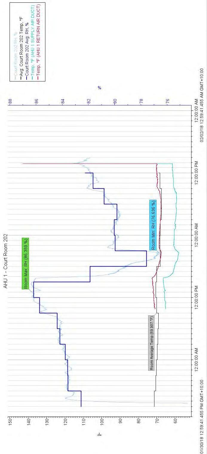
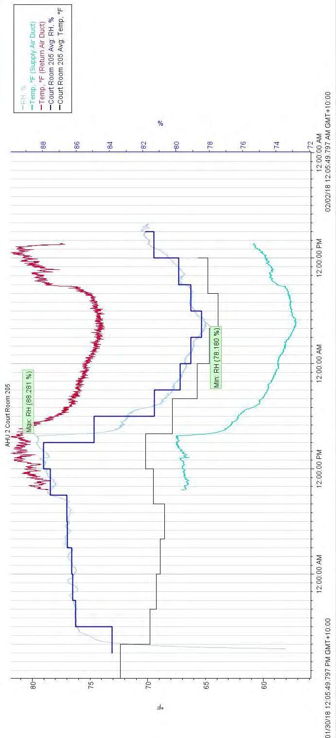
The AHU’s airflow has a noticeable drop in performance. Based on airflow taken at the registers and diffusers during the survey (see Appendix C-3), the air flow has been reduced from 19-43% of the original design parameters creating even more poor air circulation. The data collected from the survey showed that there was unusually high relative humidity over the entire building, except for the ADR/Conference room area and the server IT area which has its own air conditioning system and is independent of the chilled water system. ASHRAE standards for room dry bulb temperature and relative humidity for human comfort set the ranges at 75-78 degrees Fahrenheit (F) for summer conditions and relative humidity (RH) in a room from 40-60%. The existing rooms served by the chilled water system have room dry bulb temperatures of 68-72 degrees F and RH in the range of 6588% (see Appendix C-5). Currently, the thermostat is set at 68 degrees F and the almost time the timers have been disabled, thus allowing the unit to run continuously. This includes the AHU with dehumidifiers installed in the units. Also, interesting to note that despite the diminished capacity of the chilled water system and the air handling units, the space temperature remained colder than what is expected. It was usual to see some people have small floor mounted space heaters near their desk (see photo 5.8). An analysis was performed on the cooling load requirements based on the current use of the building (see Appendix D). Because of the many changes of room uses, such as converting an office to a storage area, or converting the library to an assembly room/storage/IT/office requires a much different cooling capacity. From the table below, it can be seen that the current load is up to 87% less than the original cooling requirement.
AHU # Installed Original cooling capacity, Tons Calculated current cooling load requirement, Tons 1 20 7.5 2 20 6.9 3 20 14.9 4 20 7.2 81
Table 1.2 Comparison of Existing AHU cooling capacity and cooling load based on current use
The design has a change of temperature of the entering and leaving temperature 10 degrees F with water entering at 45 degrees F. This should create a drop on air temperature across the cooling coils of 15-20 degrees F. Currently the existing temperature entering and leaving the coil is only 4 degrees F and the temperature drop across the cooling coils are only 1 to 3 degrees F. The elevated entering chilled water temperature at 52 degrees F reduces the AHU to reduce temperature and lower the relative humidity in the room. When the AHU’s capacity is oversized for space, the temperature can be met quickly and not allowing moisture in the air to condensate at the cooling coil. The psychometric process of air conditioning cycle is to cool and dehumidify the air as it reacts to meeting the thermostat setpoint.
The age of the equipment, the current repairs, and the refrigerant it uses, it is recommended to replace the older TRANE chillers, remote air-cooled condensers, and associated chilled water pumps. The older TRANE units are using R-22 refrigerant which had stop production in 2010 and is scheduled to be phaseout by 2020. Also, it is recommended to replace the existing AHU’s and FCU’s and its associated piping and controls because it is also at its end of useful life and it is oversized for the zones it serves. By replacing the existing AHU’s with more appropriate size units, the system will be able to control the
5 20 7.2 6 20 7.3 7 15 7.5 8 20 11.7 9 10 4.7 10 10 1.3 11 10 2.7 12 25 12.1 13 15 13.4 14 15 7.0 15 17.5 5.5 16 12.5 4.0
82
temperature, as well as, the relative humidity better in the occupied spaces. As an option, ACCU thermo-fusers VAV diffusers (see appendix G) can better control air flow into the space based on the demand for cooling by varying the amount of airflow into the space. This can reduce the energy cost of operating the air conditioning unit by reducing the fan speed during the time of low occupancy. Typically, a building would introduce outdoor requirements of a building into the AHU’s to allow the air to be pretreated before entering the building. Other outdoor air may enter the building untreated through people traffic at entry doors and infiltrate through small gaps around fenestrations in the building construction. The lack of fresh air into the AHU’s creates poor indoor air quality. Outdoor and exhaust air is required per the International Mechanical Code and ASHRAE 62.1 standard. The normal building design would keep the building under slight positive pressure by providing at most 10% more make-up air than exhaust air. Since the exhaust fans are mostly not working and the outside air dampers in the AHU’s are closed there is currently no mechanical means from the system that generates the code required fresh air and exhaust air flow rates. There is a lot of infiltration and exfiltration from the people traffic in the Main Entry where the public enters and the Back Entry where the employees enter and exit. Because the Main Entry air-conditioner is not in operation and the back entry not having any air conditioning because AHU #10 is not operational, the building’s exit and entry points are under neutral building pressure allowing untreated warm, humid outside air to enter the building thus attributing to the high humidity conditions
It is recommended to re-introduce an air conditioning system at the Main Entry, using dedicated outdoor air units to provide the required make-up air plus 10% above the required exhaust air to pressurize the building and minimize the amount of infiltration of the untreated humid outside air into the building to reduce the buildings high relative humidity. Additional, a vestibule can be added to the main entrance where the most people traffic occurs to further reduce the amount of warm outdoor air infiltrating into the building It is also recommended to incorporate a ventilation demand system into the AHU’s where occupant load varies greatly over the day. A ventilation demand system will modulate the amount of outside air in the space by using carbon dioxide (CO2) sensors to detect occupant load based on the CO2 level in the room and modulate a motorized damper in the outside
83
air ducts. This system will reduce energy cost by minimizing the amount of outside air when the zones have low occupancy. Further, it is recommended to incorporate an odor control GPS system (see appendix G) into all AHU’s and FCU’s to control the musty smell. There is no preventative maintenance plan in place for the upkeep of the air conditioning and ventilation system. It is highly recommended to incorporate a preventative maintenance plan to ensure the system is functioning optimally and to guard against major breakdowns in the system. A central building automation system is also a good tool to centrally monitor the equipment’s operation that is remotely located on the roof and is hard to access. The central monitoring station can be located in the Buildings Superintendent Office and/or maintenance service provider.
84
V. SUMMARY OF RECOMMENDATIONS
A. Remove all carpet, furniture, books, paper, clothing, and sagging ceiling tiles affected by mold. Seal building leaks in the structure and windows. Seal any duct or pipe penetration in the building envelope that may be leaking into the building.
B. Remove and replace existing air-conditioning system including TRANE chillers, chilled water pumps, remote air-cooled condensers, AHU and FCU. This would include the replacement of the two r-22 chillers with one 100 TON, R-134A chiller, removal of 2 remote air-cooled condenser and replace with on 100 TON package air-cooled chiller one roof, removal of 3 chilled water pump and replace with two variable frequency drive pumps rated at 240 GPM, 120 TDH, AHU and FCU to the appropriate size based on current use. All control will be local.
C. Add dedicated pre-cooled outside air unit at the Main Entry and Back Entry Add appropriate controls to incorporate OA dampers controlled by the CO2 sensor.
D. Add odor control system to AHU and FCU. (See brochure in appendix G)
E. Clean duct, and install higher efficiency filter (MERV-13) (See brochure in appendix G)
F. Perform Testing and Balance air distribution and chilled water to the new system.
G. Remove and replace all exhaust fans
H. Remove AHU-10 and connect ductwork to AHU-9.
I. Option, provide ACCUTHERM diffusers to allow for individual room control and retrofit VFD to the AHU (See brochure in appendix G)
J. Option to install a Building Automation System to provide central monitoring of HVAC operation at Building Superintendent office.
85
VI ESTIMATED COST
Base Mechanical:
A. Removal of existing 2 ea 100-ton Trane Chiller including its remote condensers, chilled water pump, and associated accessories. Supply and installation of a complete system of 1ea 100-ton high efficient chiller with remote condenser and option of 1ea 100-ton H.E. package chiller, including 3 ea new variable frequency drive chilled water pump, support, and accessories.
Estimated Cost: USD 2,249,891.06
B. Supply and complete installation of Precooling Coil system including demand control ventilation DCV (CO sensor) support and other accessories.
Estimated Cost: USD 532,263.03
C. Supply and Complete Installation of Odor Control System.
Estimated Cost: USD 186,515.09
D. Supply and complete replacement of Roof ventilator and Inline Exhaust Fans.
Estimated Cost: USD 139,692.10
E. Source removal, Cleaning and Sanitize Air Duct System including Supply and installation of new high efficient pleated type filter.
Estimated Cost: USD 125,260.07
86
F. Complete Removal of AHU #10 and Install ductwork to AHU #9
Estimated Cost: USD 9,332.42
G. Test and Balance Air distribution system and Chilled water system
Estimated Cost: USD 315,751.35
Options:
A. Supply and Installation of ACCU Therm-fuser VAV Diffuser for offices, including basic TAB works.
Estimated Cost: USD 435,152.61
B. Supply and Installation of Building Monitoring System (BMS) including training and supply of Hardware and software devices.
Estimated Cost: USD 366847.11
87
PART VII APPENDIX
88
A. Photos
89
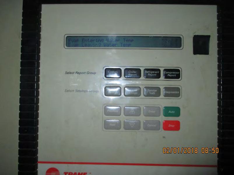
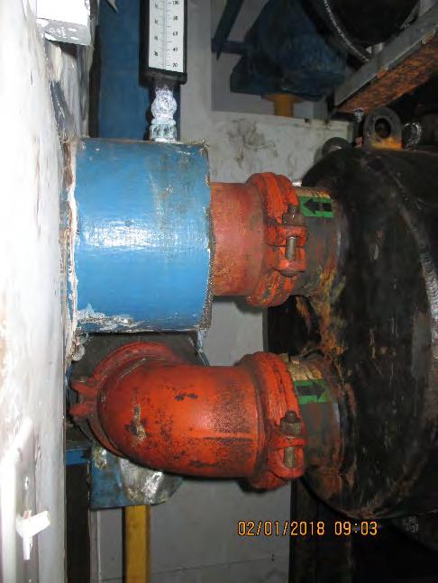
 Photo 1.0 Trane Chiller #3 control panel display of leaving and incoming chilled water temperature.
Photo 1.1 Corrosion are present on exposed chilled water piping.
90
Photo 1.2 CHW #1 200-ton Smardt Chiller (installed in 2012)
(installed
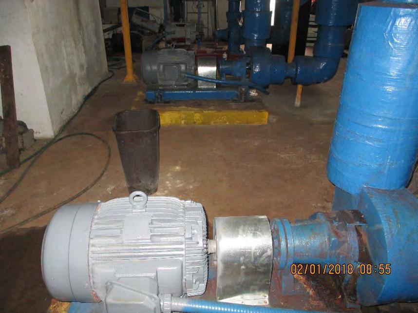

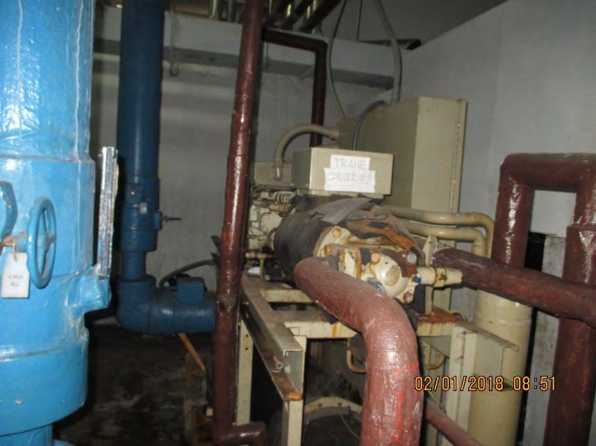 Photo 1.3 CHW #2 100-ton Trane Chiller
in 1998)
Photo 1.4 CHW #3 100-ton Trane Chiller
(installed in 1998)
91
Photo 1.5 Chilled water pump # 2 and 3
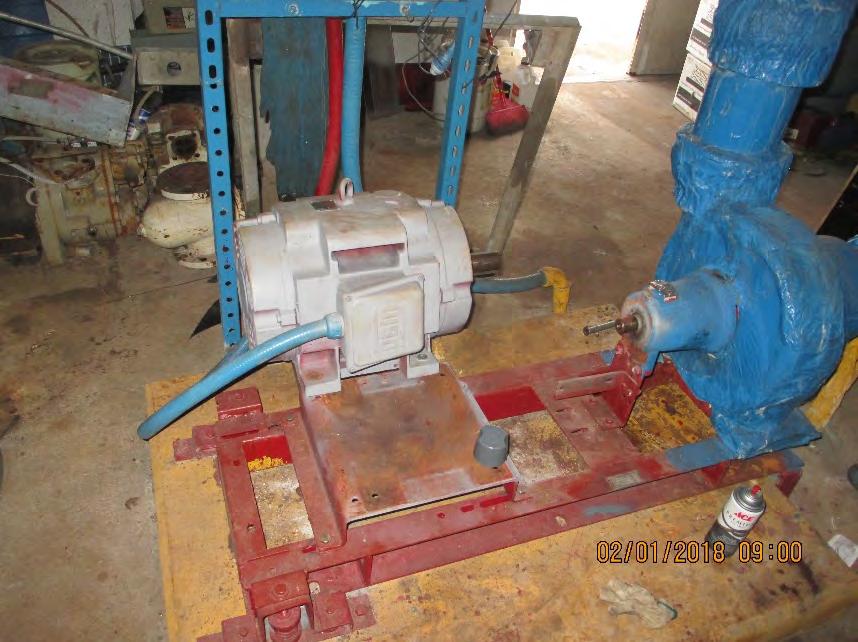
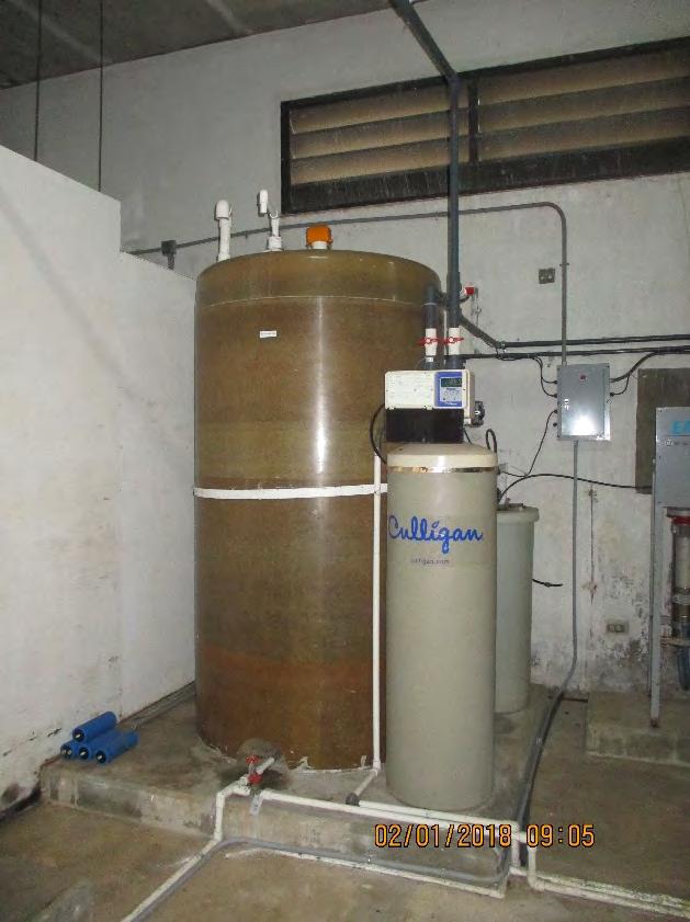 Photo 1.6 Chilled water pump # 1 (installed in 2012)
92
Photo 1.7 Chilled Water make-up with RO system
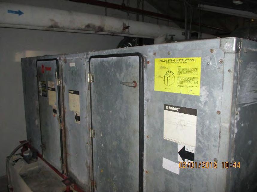
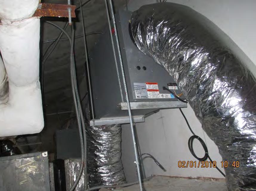
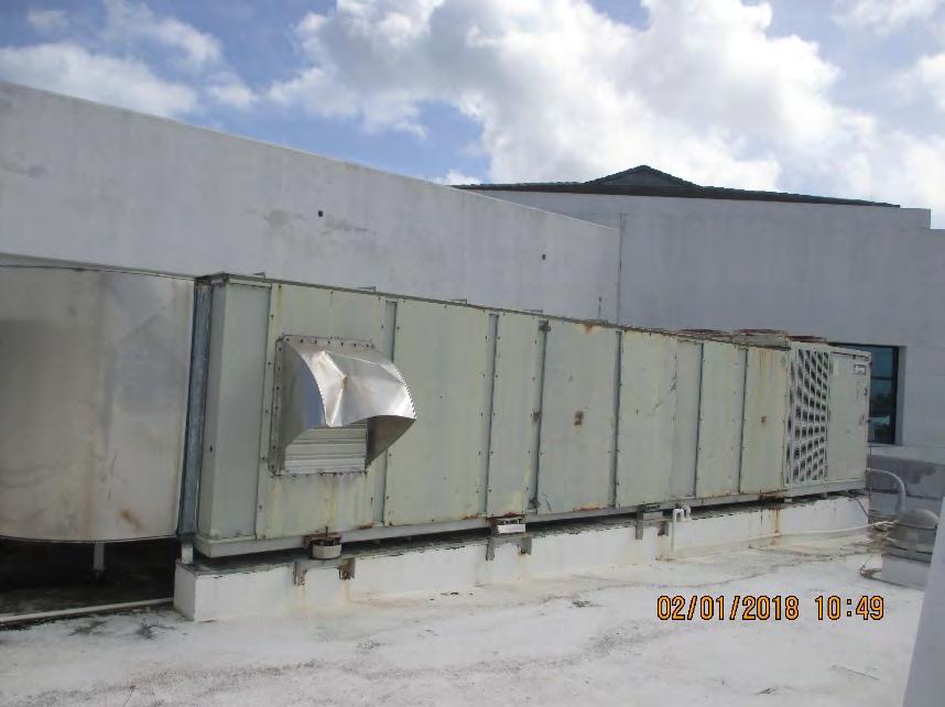 Photo 1.8 Typical TRANE Air Handling Unit (AHU)
Photo 1.9 Honeywell 120 pints Dehumidifier typical to three. (recently installed)
93
Photo 2.0 TRANE Package Cooling Unit for Public Lobby.
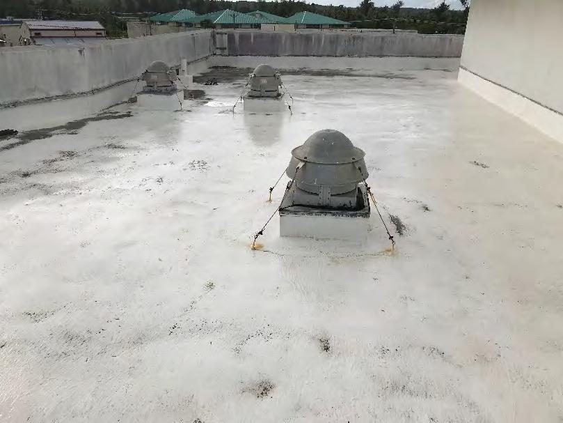
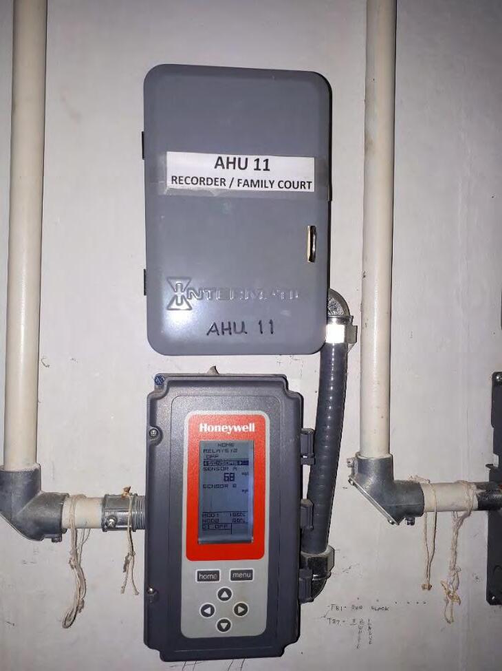 Photo 2.1 Typical Roof ventilators serving restrooms (installed 1998)
94
Photo 2.2 Honeywell Typical AHU Controller

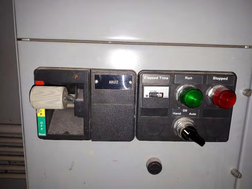 Photo 2.3 Typical AHU Controller
95
Photo 2.4 Typical AHU Main Panel
Hood is a multipurpose electronic air balancing instrument primarily used for efficiently taking direct air volume readings at diffusers and grilles
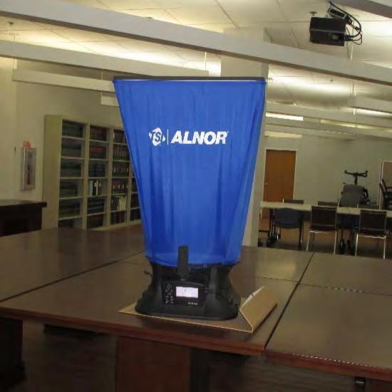
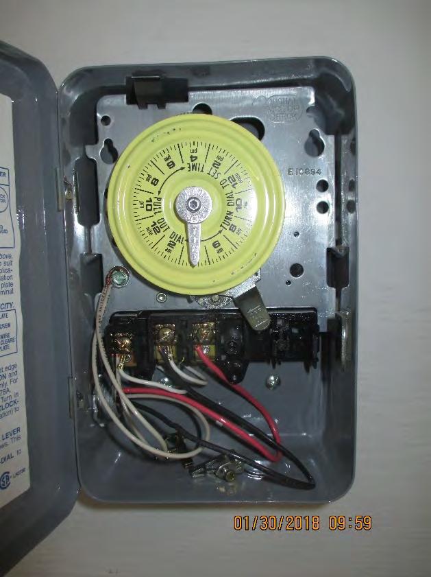 Photo 2.5 Typical AHU Timer
96
Photo 2.5 The EBT731 Balometer® Capture
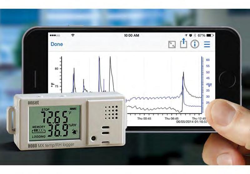
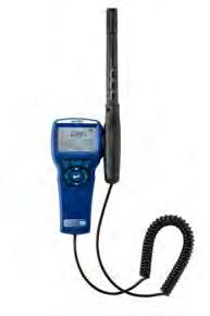
 Photo 2.6 Onset HOBO Data Loggers. Measures and transmits temperature and relative humidity data wirelessly to mobile devices via Bluetooth Low Energy (BLE) technology.
Photo 2.7 TSI's IAQ-Calc™ Indoor Air Quality Meter 7545 Measurements are CO, CO2, temperature, humidity; and calculations are dew point, wet bulb temperature, and % outside air.
97
Photo 2.8 Ahu #2 Filter Box (rusted and filter is not installed)
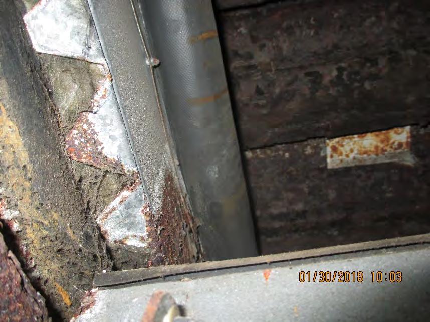
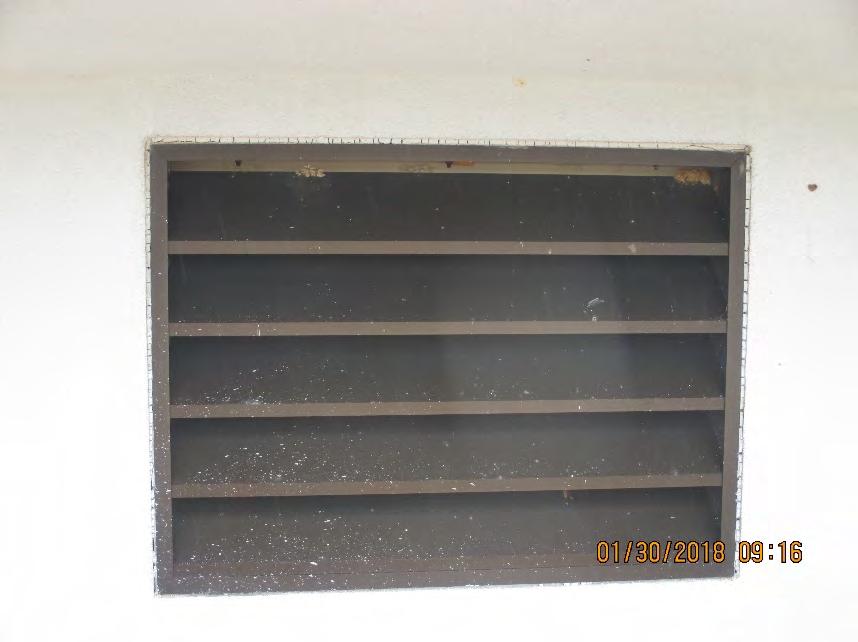
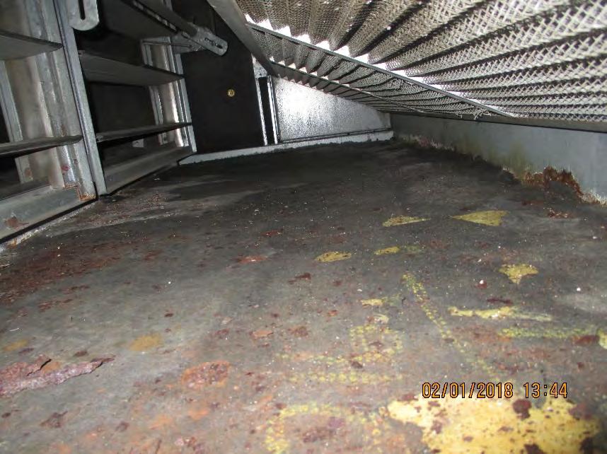 Photo 2.9 Inside view fresh air damper in one of the AHU serving the superior court. Damper is closed and corroded.
Photo 3.0 Fresh air intake louver (No protection against rain water carry-over)
98
Photo 3.1 Inside view of AHU #4 equipment base casing is corroded and insulation is starting to deteriorate.
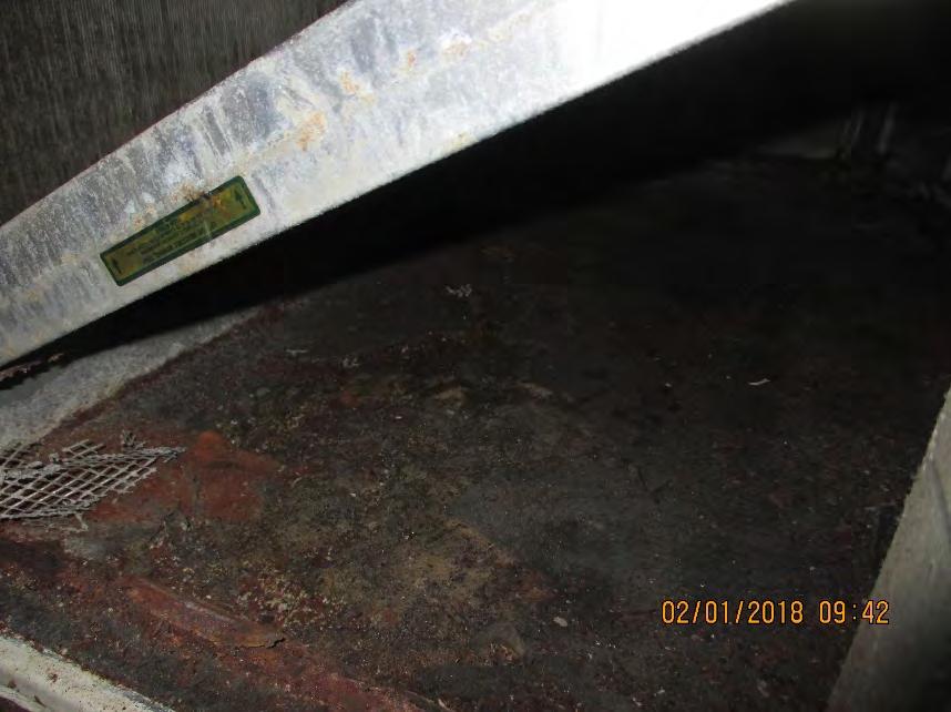

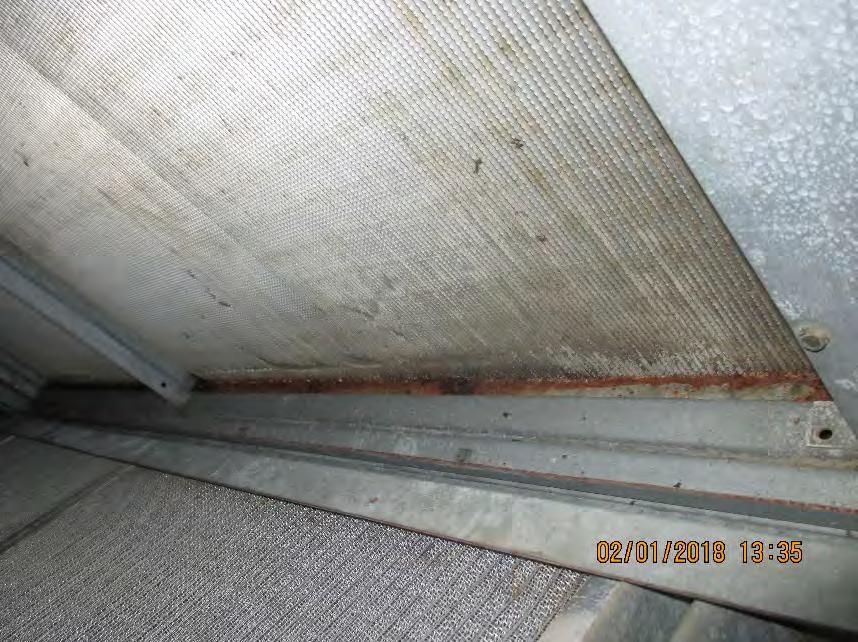 Photo 3.2 Inside view of AHU #11 equipment base casing is corroded and insulation is damped with moisture.
Photo 3.3 AHU #7 Equipment Base casing is completely missing.
99
Photo 3.4 Inside view of AHU #5 cooling coil is dry and dirty.
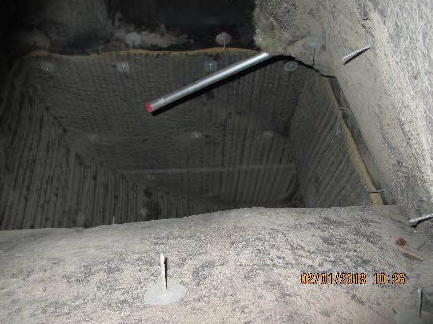
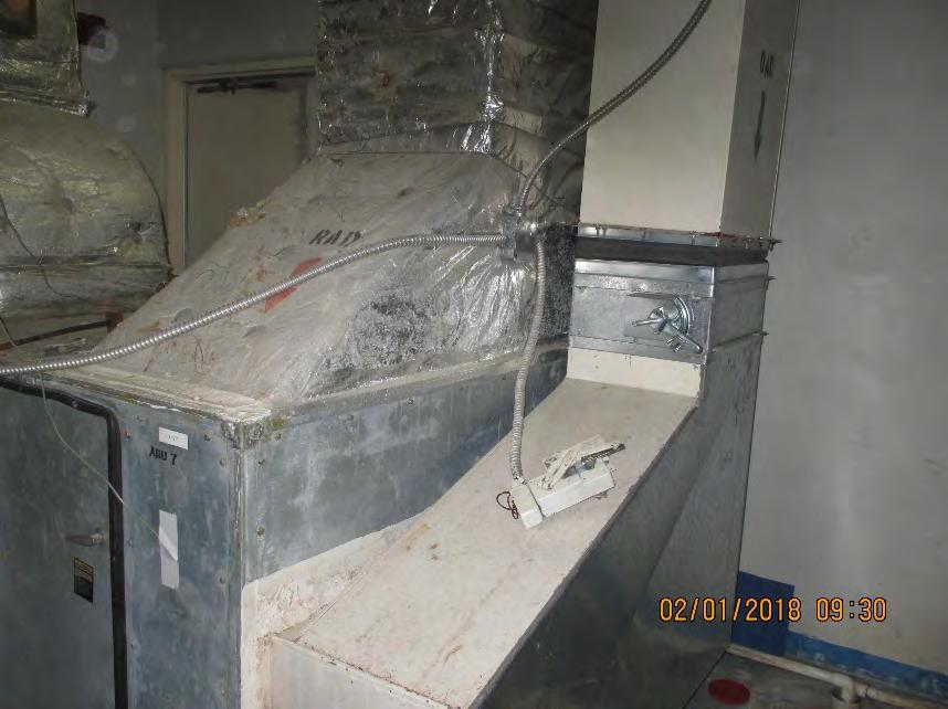
 Photo 3.5 Inside View of Air Duct System (accumulation of dust is present)
Photo 3.6 The old motorized motor and control wiring is left disconnected.
100
Photo 3.7 Fresh Air damper is closed, (Typical to all AHU)


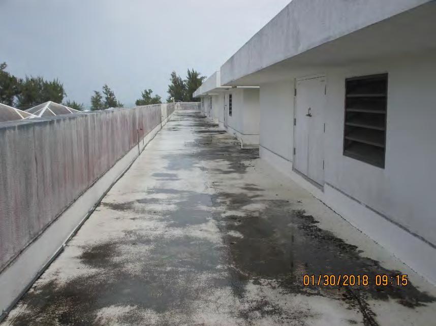 Photo 3.8 AHU #3 Dirty Cooling Coil
Photo 3.9 AHU #14 Insulation is compromised due to installation of Dehumidifier.
101
Photo 4.0 Roof water proofing is compromised.
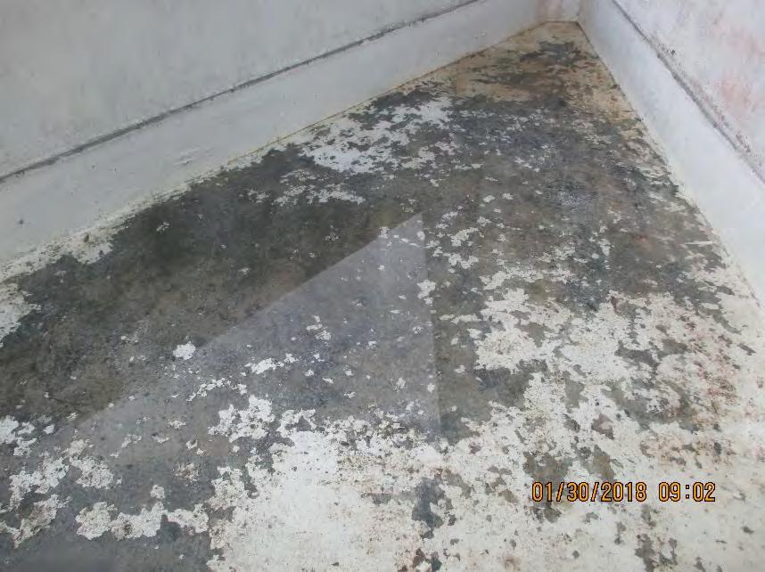
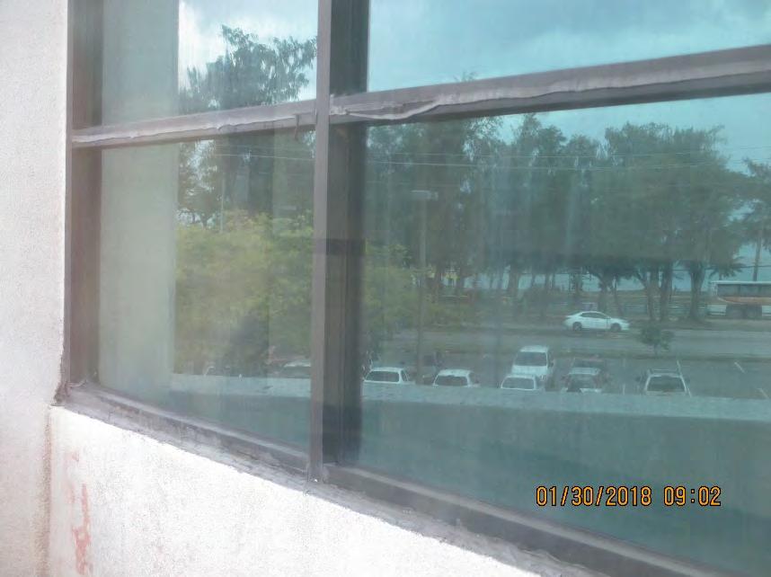 Photo 4.1 Water ponding in some area of the roof is seen.
102
Photo 4.2 Window seal on hardwares is aged and compromised.
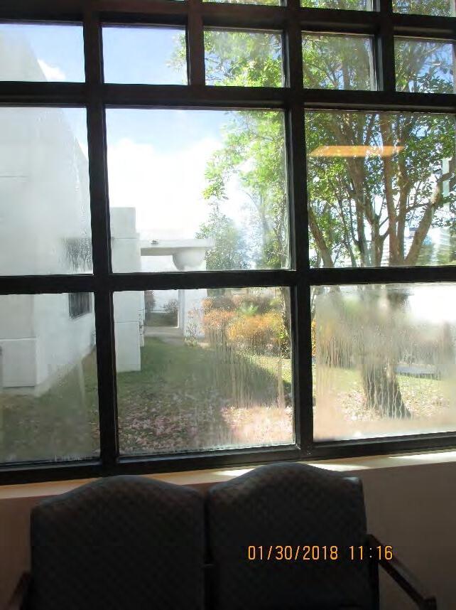
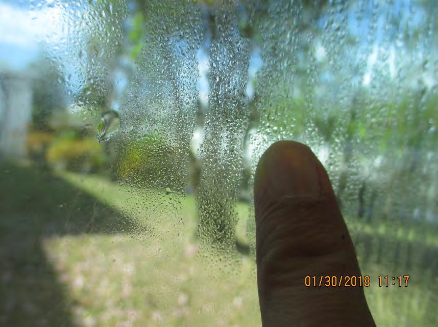 Photo 4.3 Window double panes is leaking, and condensation is present between the glass panes.
103
Photo 4.4 Window double panes is leaking, and condensation is present between the glass panes.
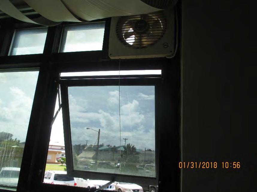
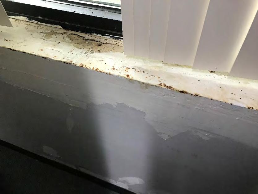
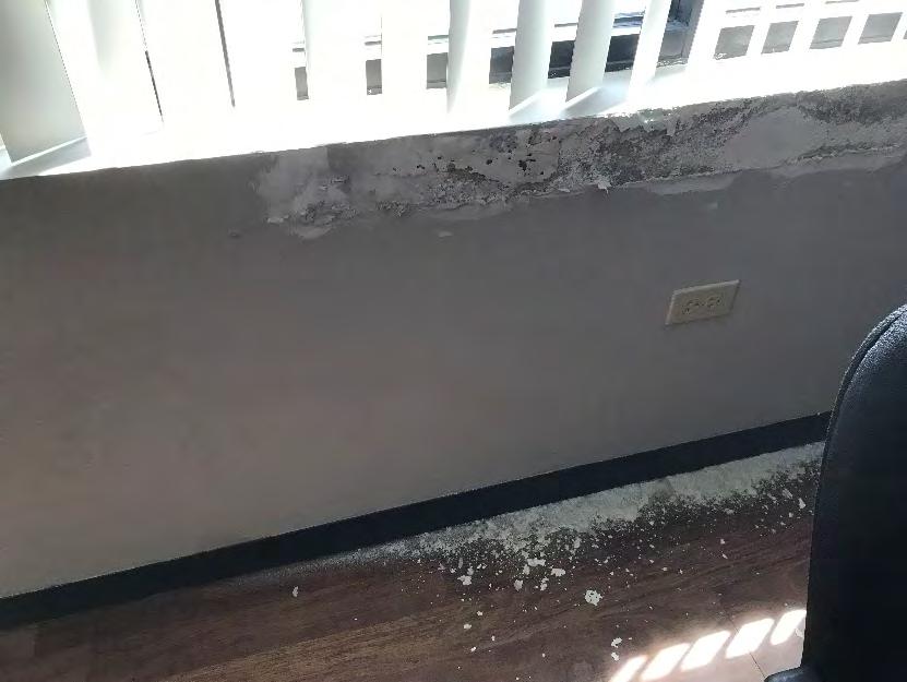 Photo 4.5 Wall exhaust fan was installed, and window is left open.
Photo 4.6 Water damage around window
104
Photo 4.7 Water damage around window
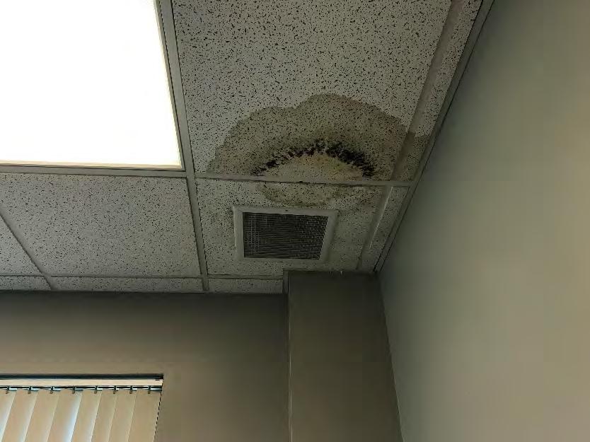
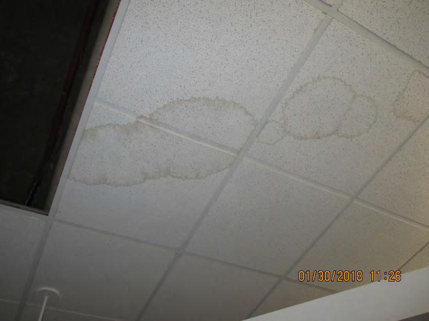
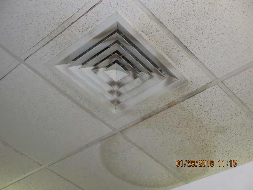 Photo 4.8 Water damage on ceiling tiles
Photo 4.9 Water damage on ceiling tiles
105
Photo 5.0 Water damage on ceiling tiles and dirty ceiling diffusers.
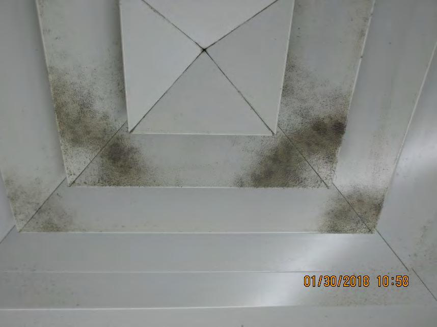
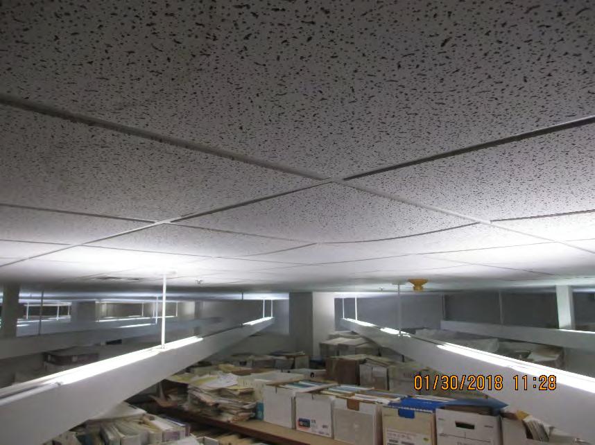
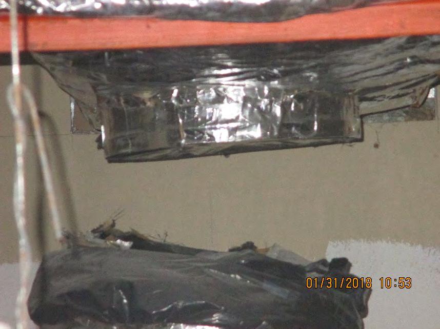 Photo 5.1 Dust particle present in ceiling diffuser (indicates ineffective AHU filter system)
Photo 5.2 Sagging ceiling tiles (indicates ceiling tiles was exposed to high humid environment.)
106
Photo 5.3 Ductwork inside ceiling are left disconnected.
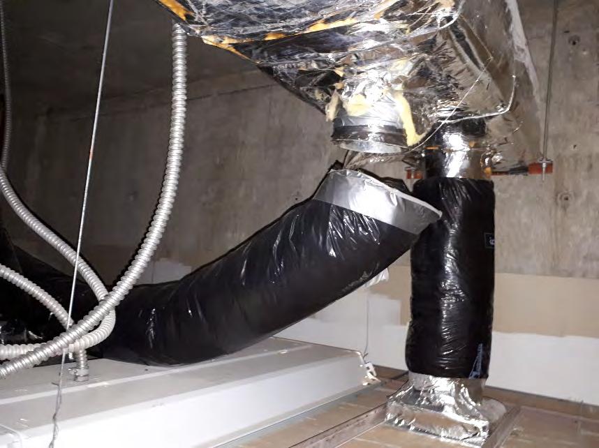
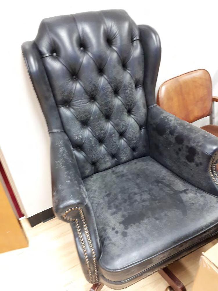 Photo 5.4 Disconnected Ductwork inside ceiling
107
Photo 5.6 Discarded office furniture are still in the premises.
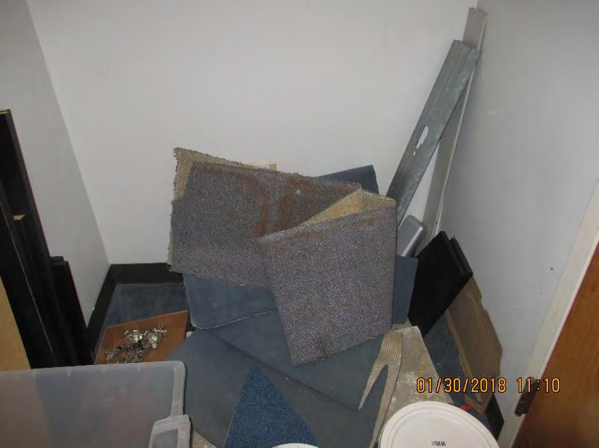
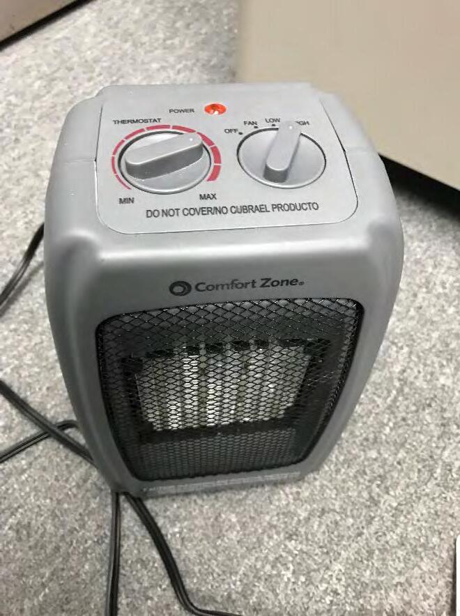 Photo 5.7 Discarded carpets are kept inside the building.
108
Photo 5.8 Space heater was seen on one of the room.

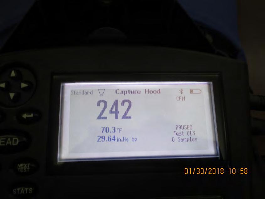 Photo 5.9 Spot reading on 2nd floor Superior court admin Corridor
109
Photo 6.0 ALNOR Flow hood reading on ceiling diffuser
B. Temperature and Relative Humidity Data Graph
110
111
112
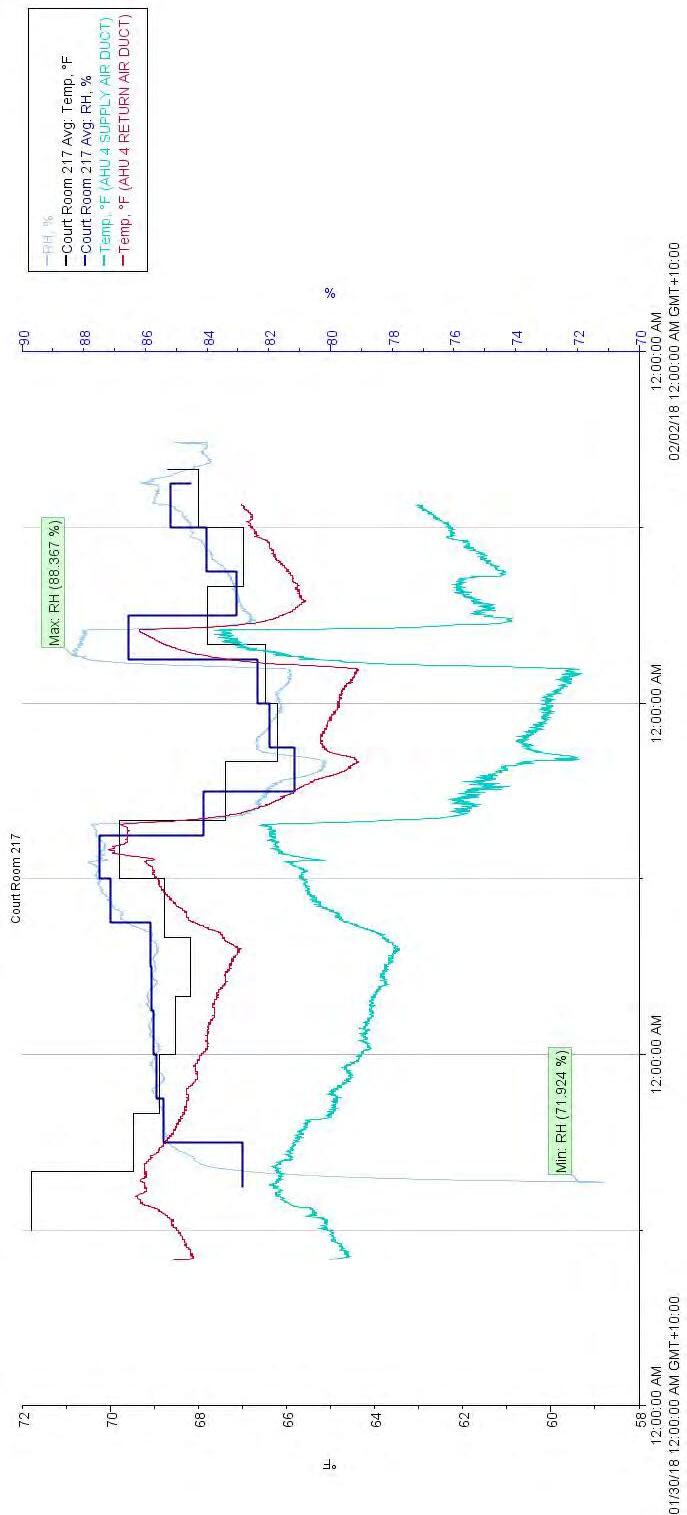
113
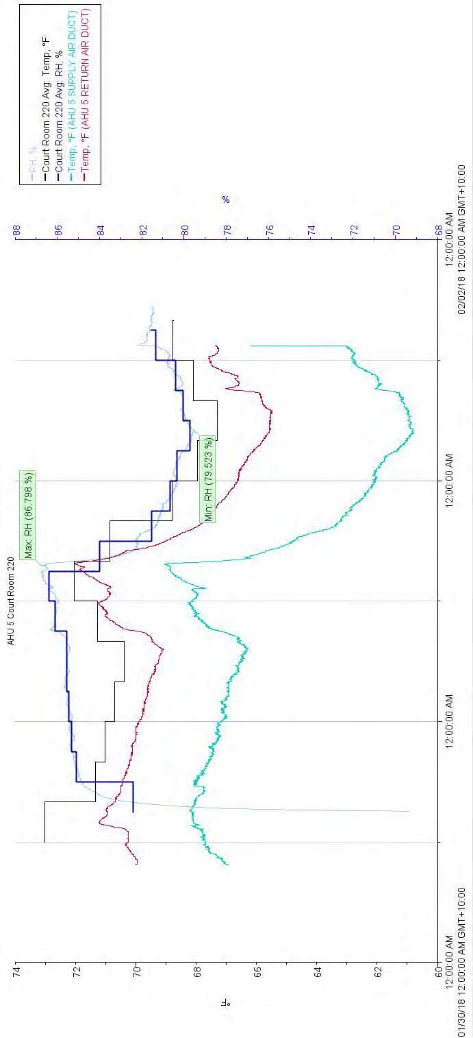
114
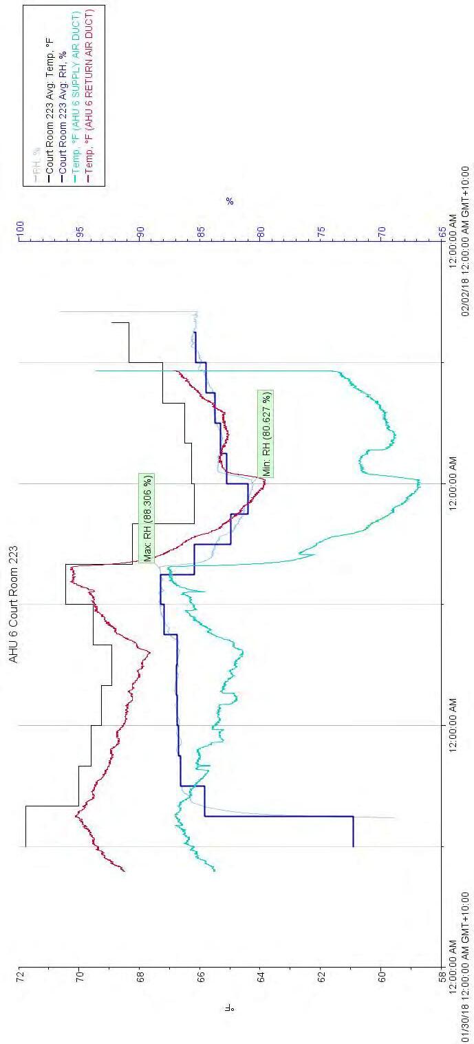
115
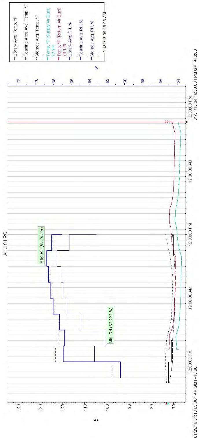
116
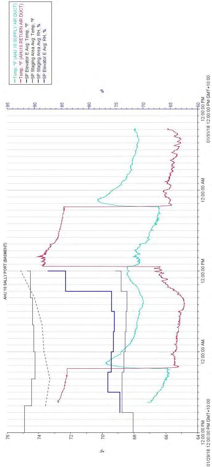
117
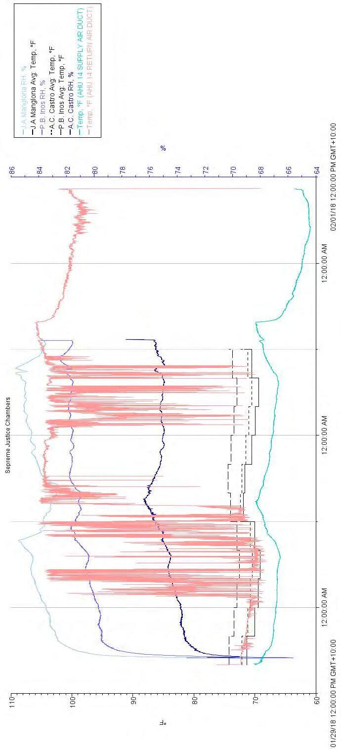
118
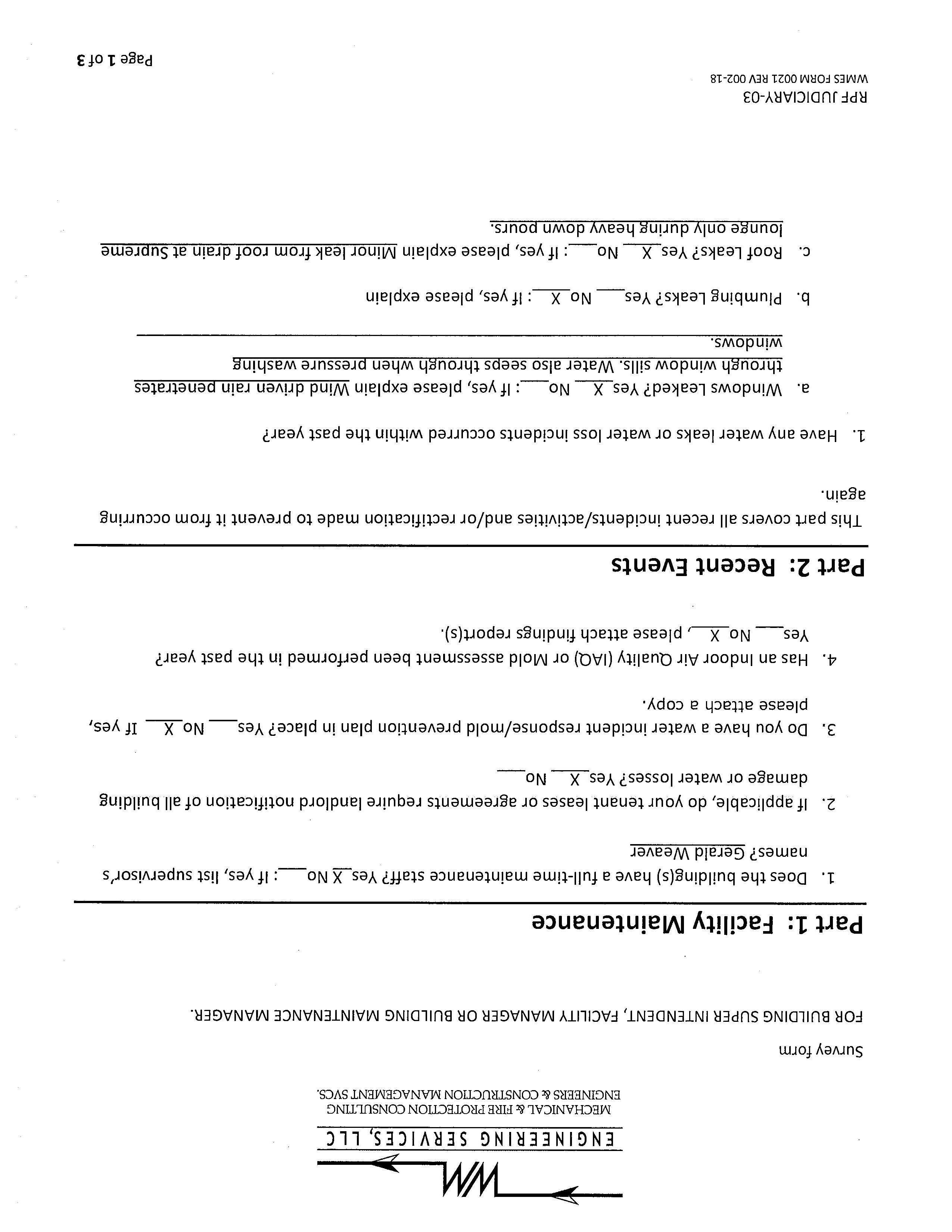
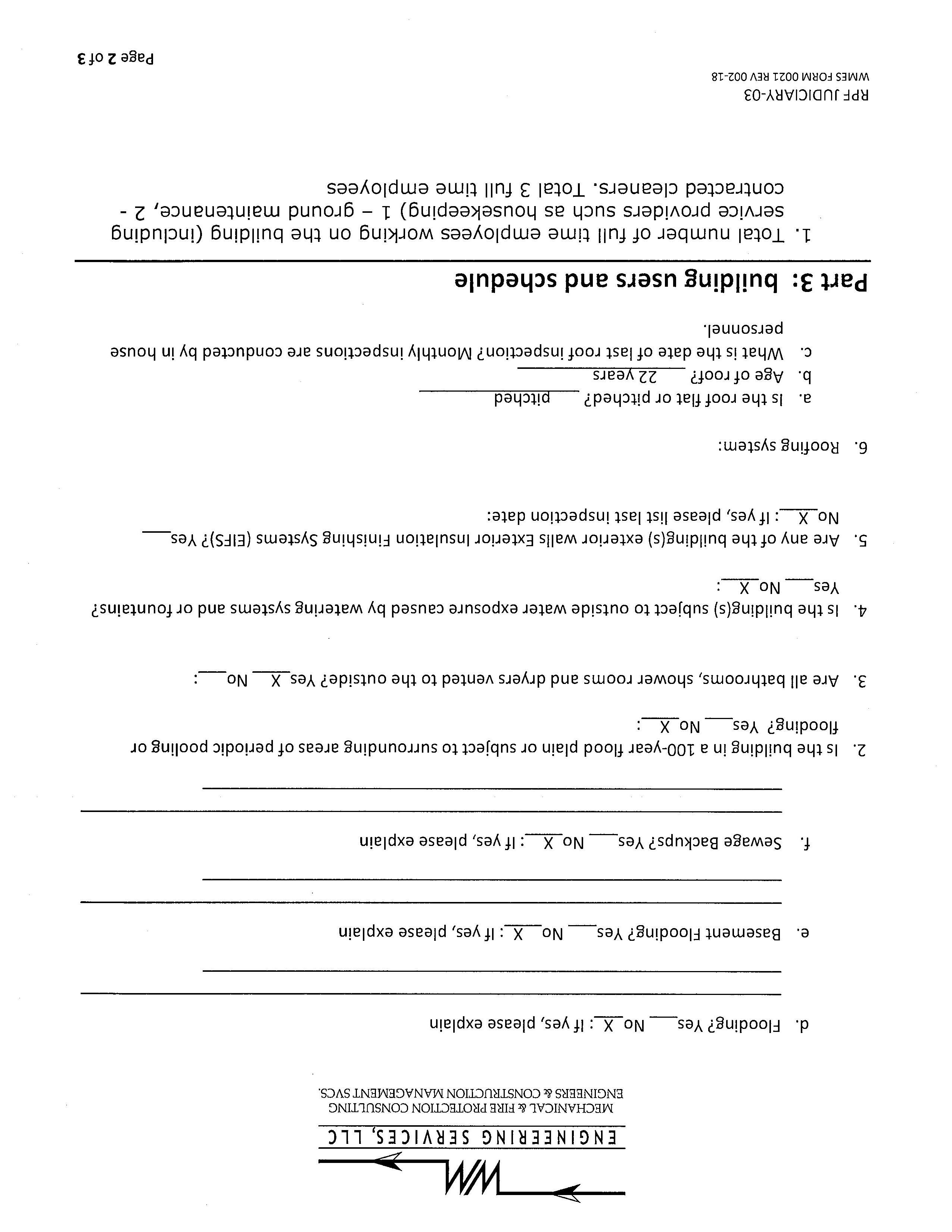
C. Survey Forms
119
Part 1: General Building Information
Building Name House of Justice
Building Function Superior and Supreme Court of Saipan
Year Built 1998
Major Renovations
Square Footage 39,000 sf
Energy Usage per year
Building Occupancy
Building Operational Hours 7:30 am – 6:00 pm (Monday to Friday)
Observed Outside Air Temperature and Conditions 80 deg-F DB, Sunny and partly cloudy with sprinklers of rain in the early morning and late at night.
Facility Manager During Audit Gerald Weaver
Building Envelope
Surface Construction Detail Major Renovation? Yes / No
If yes, when was the last
Installed with vapor barrier? Yes / No remarks
Wall – Exterior Painted Concrete walls and gypsum furring on the interior side.
Wall – Interior Gypsum board with metal studs and exposed concrete
Additional partitions are added and used for private offices and storages.
yes
-
Yes, removed the single fly membrane insulation and none
Roof Cast-in place concrete roof with single fly membrane 120
over tapered rigid insulation painted roof with water proofing
Floor Poured concrete with finished carpet, vinyl’s or ceramic tiles.
Ceiling 2x4 acoustic ceiling grid tiles on offices and painted gypsum board on courts
Window Double-pane insulated glazing glass with aluminum frame.
Carpets are currently being replaced
121
Part 2: Building System
HVAC Systems
HVAC System Description:
System consist of 3-100-ton Chiller with remote condenser located on mechanical building north side of the house of justice. chiller #1 were replace with Smart Turbocor Chiller. Air handling units are installed in 9 mechanical rooms several and Fan coil unit are installed inside ceiling of the area it served. AHU’s is a constant volume modular type central Air Handler system, FCU’s is a high static ceiling concealed ducted type. Air delivery system is insulated galvanized metal duct with flexible duct at ceiling diffusers, Temperature is maintained at 70deg. Temperature Sensor is located at main RAD and controls the chilled water flow via 3-way valve and AHU fan has a Timer control.
Chilled Water System Chiller Data Tag Year Installed If Known Mfr./Model Serial No. Chiller Type Compressor Type Capacity (Tons) Condition #3 Trane/ RTIA1104 XBO1R01R0D0VN U96H06206 100 Running #2 Trane Trane/ RTIA1104 XBO1R01R0D0VN U96H06207 100 Running #1 Smart dt EV10183 Turbocor 200 Under repair 122
Chilled Water System Pump Data (Specify for Chilled Water or Condenser Water System) Tag Description Mfr./Model Constant or Variable Flow Flow (gpm) Head (Ft) Condition 1 CHW Pump AC Motors / 5KE284BC205C CV 240 120 Running 2 CHW Pump AC Motors / 5KE284BC205C CV 240 120 Running 3 Wegnuma Wegnuma /02518T3EE284T Disassembled Con’t Chilled Water System Pump Data (Specify for Chilled Water or Condenser Water System) Tag Frame Type HP Efficiency Voltage/Phase RPM Condition 1 284T 25 230-450/3 1765 Running 2 284T 25 230-450/3 1765 Running 3 - 25 - 1770 Disassembled 123
Tag Mfr./Model Serial No. FAN HP- V/HZ/P Cooling Method Heating Method DDC Y or N Condition AHU 3 Trane K96F53573 7.5 - 460/60/3 CHW N/A N Running AHU 7 Trane K96F53025 5 - 460/60/3 CHW N/A N Running AHU 9 Trane K96F51790 3 - 460/60/3 CHW N/A N Running AHU 11 Trane K96F51930 2 - 460/60/3 CHW N/A N Running AHU 12 Trane K96F53614 7.5 -460/60/3 CHW N/A N Running AHU 13 Trane K96F53004 5 - 460/60/3 CHW N/A N Running AHU 14 Trane K96F53944 5 - 460/60/3 CHW N/A N Running DHU Honeywell / DR120A2080 G1232858 120V/60hz/ 1 DX Not working AHU 15 Trane K96F54624 5 - 460/60/3 CHW N/A N Running DHU Honeywell / DR120A2080 G1232856 120V/60hz/1 DX Not working PCU1 N/A Not working AHU 6 Trane K96F53621 7.5 - 460/60/3 CHW N/A N Running AHU 5 Trane K96F53511 7.5 - 460/60/3 CHW N/A N Running AHU 4 Trane K96F53486 7.5 - 460/60/3 CHW N/A N Running AHU 2 Trane K96F53499 5 - 460/60/3 CHW N/A N Running AHU 1 Trane K96F53564 5 - 460/60/3 CHW N/A N Running AHU 10 Trane - CHW N/A N Not working 124
Air Handling System (Chilled Water)
Fan Coil Units (DX Ductless Split Type or 5-ton DX Split Systems and Below)
Fan Coil Units (Ductless Split or Small DX Split Type)
Tag Year Installed If Known Mfr./Model Serial No. System Type Cooling Method Heating Method On DDC Y or N Condition Fcuaccu-1 Exhaust or Supply Fans Exhaust or Supply Fans Tag Year Installed If Known Mfr./Model Serial No. System Type HP Voltage On DDC Y or N Condition 10 GRC DRX-10 333207 RV 1/20 115/60H2 1650 11 GRC DRX-10 333208 RV 1/8 115/60H2 1140 9 GRC DRX-8 333206 RV 1/20 115/60H2 1050 125
Cooling Tower for Water-Cooled Chiller Plant
2018-02-01
Tower Tag Year Installed If Known Mfr./Model Serial No. System Type FAN HP Capacity (Tons) On DDC Y or N Condition
and Operational Characteristics Type of Controls (DDC, Electric, Pneumatic, Time clocks) Timer, Manufacturer/Vendor Honeywell Connected to Base-wide EMCS No Building Occupancy Scheduling No Completed by Name:
Date:
126
Cooling
Controls
Ricky Viador


PROJECT: NO. TYPE SIZE SUPPLY RETURN VEL CFM VEL CFM Witness Waiting 202B 1 CD 15x15 360 129 2 RR 12x16 280 260 Vest 202A 3 CD 6X6 60 70 4 CD 6X6 60 72 5 RR 8X6 120 79 6 RR 8X6 86 ATTY. Conf. 202C 7 CD 15X15 360 360 8 RR 12X8 300 Superior Court 202 9 CD 15X15 400 249 10 CD 15X15 400 325 11 CD 15X15 400 180 12 CD 15X15 400 249 13 CD 15X15 400 231 14 CD 15X15 400 170 15 CD 15X15 360 380 16 CD 15X15 360 315 17 CD 15X15 360 259 18 CD 15X15 360 175 19 CD 15X15 360 262 20 CD 15X15 360 153 21 RR 30X12 1760 325 22 RR 24X12 518 NDD 23 RR 24X12 446 NDD 24 RR 30X12 1760 375 544 25 CD 9X9 110 75 26 CD 9X9 110 86 27 CD 9x9 110 58 28 CD 9X9 110 65 29 CD 9X9 105 59 30 SR 12X8 105 408 128 31 SR 12X8 105 301 113 32 SR 12X8 105 582 181 33 RR 24X12 105 1170 596 679 34 RR 21X12 318 NDD 35 CD 9X9 110 68 36 CD 9X9 110 70 37 CD 9X9 110 73 38 CD 9X9 110 78 39 CD 9X9 105 60 40 SR 14X8 350 386 120 41 SR 14X8 350 340 107 42 SR 14X8 350 290 90 43 RR 24X12 1170 559 637 44 RR 24X12 359 NDD 7960 6560 5010 4251 37% Change in Supply Air Quantity TEST DATE: Legend NDD - not in design documents - no access 1-Feb-18 READINGS BY: WM/RV TOTAL DESIGN ACTUAL
SYSTEM/UNIT: AHU - 1 AREA SERVED OUTLET DESIGN SUPPLY RETURN REMARKS WM ENGINEERING SERVICES, LLC P.O. Box 392, Hagåtña, Guam 96932 T: (671) 646-8127 F: (671) 646-0704 E: main@wmesguam.com 130
AIR OUTLET TEST REPORT House of Justice, Saipan
House of Justice, Saipan

PROJECT: NO. TYPE SIZE SUPPLY RETURN VEL CFM VEL CFM 205A (Vest) 1 CD 9X9 130 49 2 RR 8X4 100 35 205B (Atty. Conf) 3 CD 15X15 370 370 4 RR 12X8 320 205 5 CD 15X15 192 Superior Courtroom 6 CD 15X15 373 262 7 CD 15X15 373 217 8 CD 15X15 373 239 9 CD 15X5 373 221 10 CD 15X15 373 190 11 CD 15X15 373 229 12 CD 15X15 373 221 13 CD 15X15 373 212 14 CD 15X15 373 229 15 CD 15X15 373 223 16 CD 15X15 373 236 17 RR 30X12 1830 306 446 18 RR 30X12 349 NDD 19 RR 30X12 391 NDD 20 RR 30X12 1830 285 415 21 CD 9X9 95 74 22 CD 9X9 95 79 23 CD 9X9 95 102 24 CD 9X9 95 67 25 CD 9X9 95 79 26 SR 14X8 330 335 210 27 SR 14X8 330 430 269 28 SR 14X8 330 555 346 29 RR 24X12 1170 502 572 30 RR 24X12 570 NDD 31 CD 9X9 95 77 32 CD 9X9 95 89 33 CD 9X9 95 99 34 CD 9X9 95 56 35 CD 9X9 95 79 36 SR 14X8 330 521 326 37 SR 14X8 330 435 272 38 SR 14X8 330 401 250 39 RR 24X12 1170 595 678 40 RR 21X12 1170 410 NDD 8703 6420 5564 3866 36% Change in Supply Air Quantity TEST DATE: Legend NDD - not in design documents - no access
AIR OUTLET TEST REPORT
SYSTEM/UNIT: AHU-2 AREA SERVED OUTLET DESIGN SUPPLY RETURN 1-Feb-18 READINGS BY: WM/RV REMARKS TOTAL DESIGN ACTUAL WM ENGINEERING SERVICES, LLC P.O. Box 392, Hagåtña, Guam 96932 T: (671) 646-8127 F: (671) 646-0704 E: main@wmesguam.com 131

PROJECT: NO. TYPE SIZE SUPPLY RETURN VEL CFM VEL CFM Corridor 207 1 CD 9X9 120 81 2 CD 9X9 100 90 3 CD 9X9 100 94 4 CD 15X15 400 112 5 CD 15X15 400 88 6 CD 15X15 400 109 7 CD 12X12 300 106 8 CD 12X12 300 89 9 RR 18X12 110 408 Jury 208 10 CD 12X12 200 94 11 CD 12X12 60 34 12 CD 12X12 260 133 13 RR 10X10 400 136 Electrical Room 14 SR 9X9 230 272 15 RR 6X4 60 16 RR 0 NDD Storage 211 17 CD 8X6 100 45 18 RR 6X4 90 140 Associate Judge 19 RR 10X10 118 NDD 20 CD 13X12 320 203 21 CD 12X12 160 114 22 RR 12X8 430 Working Room 213 R.C 23 CD 15X15 360 360 24 RR 12X6 325 25 RR 81 26 RR 24X12 1140 34 27 CD 12X12 300 59 Associate Judge K.L. 28 CD 15X15 400 563 29 CD 9X9 150 150 30 RR 12X12 495 405 President Judge 215 31 CD 12X12 220 99 32 CD 18X18 600 110 33 RR 12X12 740 342 Receptionist 34 SR 10X4 100 41 35 SR 10X4 100 55 36 SR 10X4 100 48 37 SR 10X4 100 46 38 SR 10X4 100 49 39 SR 10X4 100 52 40 CD 12X12 200 200 41 CD 12X12 200 200 42 CD 12X12 250 250 43 RR 12X6 360 44 RR 12X6 360 45 RR 6X6 200 Associate Judge 224 46 CD 15X15 500 210 WM Bogdan 47 CD 9X9 180 57 48 RR 12X12 610 223 Associate Judge 225 49 CD 12X12 270 139 JN Camacho 50 CD 15X15 500 325 51 RR 12X12 700 155 8180 6020 4677 2042 43% Change in Supply Air Quantity TEST DATE: Legend NDD - not in design documents - no access READINGS BY: WM/RV REMARKS TOTAL DESIGN ACTUAL
House of Justice, Saipan SYSTEM/UNIT: AHU-3 AREA SERVED OUTLET DESIGN SUPPLY RETURN WM ENGINEERING SERVICES, LLC P.O. Box 392, Hagåtña, Guam 96932 T: (671) 646-8127 F: (671) 646-0704 E: main@wmesguam.com 132
AIR OUTLET TEST REPORT
TEST REPORT
WM ENGINEERING SERVICES, LLC

P.O. Box 392, Hagåtña, Guam 96932
T: (671) 646-8127 F: (671) 646-0704 E: main@wmesguam.com 133
PROJECT: NO. TYPE SIZE SUPPLY RETURN VEL CFM VEL CFM 225A Vest 1 CD 9X9 130 56 2 CD 9X9 88 NDD 3 RR 8X4 100 86 4 RR 8X4 98 NDD 255C Witness Waiting 5 CD 15X15 360 270 6 RR 12X6 260 165 7 RR 12X6 123 NDD 225B Atty. Conf. 8 CD 15X15 360 360 9 RR 12X6 300 25 Superior Court Room 10 CD 15X15 380 257 11 CD 15X15 380 380 12 CD 15X15 380 246 13 CD 15X15 380 299 14 CD 15X15 380 262 15 CD 15X15 380 292 16 CD 15X15 400 144 17 CD 15X15 400 308 18 CD 15X15 400 290 19 CD 15X15 400 336 20 CD 15X15 400 242 21 CD 15X15 400 240 22 RR 30X12 1160 426 618 23 RR 30X12 318 NDD 24 RR 30X12 374 NDD 25 RR 30X12 1160 656 951 26 CD 9X9 110 75 27 CD 9X9 110 90 28 CD 9X9 110 97 29 CD 9X9 110 126 30 CD 9X9 110 79 31 SR 14X8 350 690 431 32 SR 14X8 350 544 340 33 SR 14X8 350 562 351 34 RR 24X12 1170 410 467 35 RR 24X12 390 NDD 36 CD 9X9 110 93 37 CD 9X9 110 70 38 CD 9X9 110 80 39 CD 9X9 110 104 40 CD 9X9 110 73 41 SR 14X8 350 393 245 42 SR 14X8 350 389 243 43 SR 14X8 350 477 299 44 RR 24X12 1170 379 432 45 RR 24X12 372 NDD 8730 5320 6866 4394 21% Change in Supply Air Quantity
- no access READINGS BY: WM/RV REMARKS TOTAL DESIGN ACTUAL
TEST DATE: Legend NDD - not in design documents
SYSTEM/UNIT: AHU
4 AREA SERVED OUTLET DESIGN SUPPLY RETURN
AIR OUTLET
House of Justice, Saipan
-

PROJECT: NO. TYPE SIZE SUPPLY RETURN VEL CFM VEL CFM 225A Vest 1 CD 9X9 130 56 2 CD 9X9 88 NDD 3 RR 8X4 100 86 4 RR 8X4 98 255C Witness Waiting 5 CD 15X15 360 270 6 RR 12X6 260 165 7 RR 12X6 123 NDD 225B Atty. Conf. 8 CD 15X15 360 360 9 RR 12X6 300 25 Superior Court Room 10 CD 15X15 380 232 11 CD 15X15 380 129 12 CD 15X15 380 413 13 CD 15X15 380 340 14 CD 15X15 380 378 15 CD 15X15 380 209 16 CD 15X15 400 212 17 CD 15X15 400 268 18 CD 15X15 400 312 19 CD 15X15 400 334 20 CD 15X15 400 244 21 CD 15X15 400 301 22 RR 30X12 1160 426 618 23 RR 30X12 581 NDD 24 RR 30X12 557 NDD 25 RR 30X12 1160 656 951 26 CD 9X9 110 75 27 CD 9X9 110 90 28 CD 9X9 110 97 29 CD 9X9 110 126 30 CD 9X9 110 79 31 SR 14X8 350 690 431 32 SR 14X8 350 544 340 33 SR 14X8 350 562 351 34 RR 24X12 1170 410 467 35 RR 24X12 390 NDD 36 CD 9X9 110 93 37 CD 9X9 110 70 38 CD 9X9 110 80 39 CD 9X9 110 104 40 CD 9X9 110 73 41 SR 14X8 350 393 245 42 SR 14X8 350 389 243 43 SR 14X8 350 477 299 44 RR 24X12 1170 379 432 45 RR 24X12 372 NDD 8730 5320 6942 4840 20% Change in Supply Air Quantity
DATE: Legend NDD
not in design documents - no access
TEST
-
Justice, Saipan SYSTEM/UNIT: AHU - 4 AREA SERVED OUTLET DESIGN SUPPLY RETURN
BY: WM/RV REMARKS TOTAL DESIGN ACTUAL WM ENGINEERING SERVICES, LLC P.O. Box 392, Hagåtña, Guam 96932 T: (671) 646-8127 F: (671) 646-0704 E: main@wmesguam.com 134
AIR OUTLET TEST REPORT House of
READINGS
AIR OUTLET TEST REPORT

PROJECT: NO. TYPE SIZE SUPPLY RETURN VEL CFM VEL CFM 225A Vest 1 CD 9X9 130 56 2 CD 9X9 88 NDD 3 RR 8X4 100 86 4 RR 8X4 98 255C Witness Waiting 5 CD 15X15 360 270 6 RR 12X6 260 165 7 RR 12X6 123 NDD 225B Atty. Conf. 8 CD 15X15 360 360 9 RR 12X6 300 25 Superior Court Room 10 CD 15X15 380 226 11 CD 15X15 380 254 12 CD 15X15 380 222 13 CD 15X15 380 286 14 CD 15X15 380 191 15 CD 15X15 380 291 16 CD 15X15 400 220 17 CD 15X15 400 327 18 CD 15X15 400 270 19 CD 15X15 400 245 20 CD 15X15 400 222 21 CD 15X15 400 281 22 RR 30X12 1160 426 618 23 RR 30X12 359 NDD 24 RR 30X12 245 NDD 25 RR 30X12 1160 656 951 26 CD 9X9 110 75 27 CD 9X9 110 90 28 CD 9X9 110 97 29 CD 9X9 110 126 30 CD 9X9 110 79 31 SR 14X8 350 690 431 32 SR 14X8 350 544 340 33 SR 14X8 350 562 351 34 RR 24X12 1170 410 467 35 RR 24X12 390 NDD 36 CD 9X9 110 93 37 CD 9X9 110 70 38 CD 9X9 110 80 39 CD 9X9 110 104 40 CD 9X9 110 73 41 SR 14X8 350 393 245 42 SR 14X8 350 389 243 43 SR 14X8 350 477 299 44 RR 24X12 1170 379 432 45 RR 24X12 372 NDD 8730 5320 6605 4306 24% Change in Supply Air Quantity
design documents - no access
TEST DATE: Legend NDD - not in
SYSTEM/UNIT: AHU - 4 AREA SERVED OUTLET DESIGN SUPPLY RETURN READINGS BY: WM/RV REMARKS TOTAL DESIGN ACTUAL WM ENGINEERING SERVICES, LLC P.O. Box 392, Hagåtña, Guam 96932 T: (671) 646-8127 F: (671) 646-0704 E: main@wmesguam.com 135
House of Justice, Saipan

PROJECT: NO. TYPE SIZE SUPPLY RETURN VEL CFM VEL CFM 232 Sto. 1 CD 9X9 128 163 1A RR 8X4 115 0 Jury 231 2 CD 12X12 300 252 3 CD 12X12 328 226 4 RR 12X12 555 324 Jury 230 5 CD 1 250 295 6 CD 12X12 320 280 7 RR 12X12 505 408 Conf. 229 (Employees Lounge) 8 CD 12X12 325 292 9 CD 15X15 380 392 10 RR 12x12 625 442 233 Cott. 11 CD 12X12 225 168 12 CD 12X12 225 193 13 CD 12X12 225 249 14 CD 12X12 225 259 15 CD 12X12 225 174 16 CD 15X15 400 108 17 CD 15X15 400 111 18 CD 15X15 400 100 19 CD 12X12 325 88 20 CD 12X12 325 81 21 CD 12X12 325 92 22 CD 12X12 325 69 NDD 23 RR 24X24 3060 1096 24 RR 18X10 426 NDD Lounge 226 25 CD 12X12 300 19 26 CD 15X15 355 337 27 RR 12X12 580 332 Office 28 CD 12X12 114 NDD 29 CD 12X12 122 NDD 30 RR 12X6 NDD Copy/File 31 CD 12X12 94 NDD 32 CD 12X12 87 NDD 33 RR 12X6 127 NDD Office 34 CD 12X12 89 NDD 35 CD 12X12 68 NDD 36 RR 12X6 112 NDD Office 37 CD 12X12 82 NDD 38 CD 12X12 24 NDD 39 RR 12X6 62 NDD Storage 40 CD 12X12 95 NDD 41 RR 12X6 NDD 6891 4860 4723 3329 31% Change in Supply Air Quantity TEST DATE: Legend NDD - not in design documents - no access 1-Feb-18 READINGS BY: WM/RV REMARKS TOTAL DESIGN ACTUAL AIR OUTLET TEST REPORT
of Justice, Saipan SYSTEM/UNIT: AREA SERVED OUTLET DESIGN SUPPLY RETURN WM ENGINEERING SERVICES, LLC P.O. Box 392, Hagåtña, Guam 96932 T: (671) 646-8127 F: (671) 646-0704 E: main@wmesguam.com 136
House

PROJECT: NO. TYPE SIZE SUPPLY RETURN VEL CFM VEL CFM Supreme Clerk of Court & Court Admin Corr 116 1 CD 15X15 306 415 2 RR 12X12 158 Office 100 3 CD 15X15 454 292 4 RR 10X8 374 181 Office 101 5 CD 9X9 128 124 6 RR 8X4 106 93 Office 7 CD 12X12 240 148 8 RR 18X12 800 52 Office 9 CD 12X12 240 239 10 RR 10X10 370 NDD Hallway 11 CD 12X12 245 129 Office 12 CD 12X12 245 237 Breakrom 13 CD 15X15 340 554 14 RR 12X12 560 456 File Room 15 CD 15X15 340 227 Office 106 16 CD 15X15 485 483 17 RR 10X10 402 365 Office 107 18 CD 15X15 452 222 19 RR 10X8 372 270 20 RR 10X8 46 NDD Recept109/Secretary108 21 CD 12X12 215 306 22 CD 12X12 215 231 23 CD 12X12 240 261 24 RR 18X18 554 340 Recpt. 104 25 CD 15X15 422 188 26 RR 10X8 384 282 27 RR 387 NDD Clerk 103 28 CD 12X12 266 259 29 RR 12X12 164 Supreme Court Lobby 113 30 CD 24X16 710 323 31 CD 24X16 710 436 32 RR 18X12 566 457 33 RR 18X12 566 500 6253 4684 5074 4121 19% Change in Supply Air Quantity TEST DATE: Legend NDD - not in design documents - no access 1-Feb-18 READINGS BY: WM/RV REMARKS TOTAL DESIGN ACTUAL AIR OUTLET TEST REPORT House of Justice, Saipan SYSTEM/UNIT: AHU - 13 AREA SERVED OUTLET DESIGN SUPPLY RETURN WM ENGINEERING SERVICES, LLC P.O. Box 392, Hagåtña, Guam 96932 T: (671) 646-8127 F: (671) 646-0704 E: main@wmesguam.com 137
AIR OUTLET TEST REPORT House

PROJECT: NO. TYPE SIZE SUPPLY RETURN VEL CFM VEL CFM Robing 112 1 CD 15X15 422 230 2 RR 10X8 360 95 Conf. 115 3 CD 12x12 237 179 4 CD 12X12 237 204 5 CD 12X12 237 132 6 CD 12X12 237 140 7 RR 18X12 412 Clerk 117 8 CD 9X9 964 126 9 RR 6X6 70 10 RR 6X6 64 76 Justice 112 11 CD 15X15 372 25 12 CD 15X15 372 160 13 RR 345 Justice 124 (Manglona) 14 CD 15X15 336 360 15 CD 15X15 336 303 16 RR 18X12 572 Clerk 123 17 CD 9X9 96 109 18 RR 6X6 80 82 Justice 130 (Inos) 19 CD 15X15 336 246 20 CD 15x15 336 554 21 RR 18X12 572 339 22 RR 18X12 94 NDD Clerk 128 23 CD 9X9 96 69 24 RR 8X6 108 Lounge 134 25 CD 12x12 266 363 26 CD 12X12 266 19 27 RR 18X6 494 132 Visiting Judge 133 28 CD 15X15 322 175 29 RR 10X6 274 159 30 RR 10X6 228 NDD Working Room 132 31 CD 15X15 362 212 32 RR 10X6 274 33 RR 10X6 NDD Open Office 118 34 CD 12x12 296 248 35 CD 12X12 296 227 36 CD 12X12 192 185 37 CD 12X12 192 214 38 CD 12X12 192 348 39 CD 9X9 52 52 40 RR 10X10 480 99 41 RR 20X20 630 NDD 42 RR 20X20 876 NDD Secretary 181B 43 CD 12X12 53 NDD 44 RR 8X6 39 NDD Secretary 181A 45 CD 12X12 53 NDD 46 RR 8X6 40 NDD Secretary 181 47 CD 12X12 43 NDD 48 RR 8X6 39 NDD 7050 3170 5029 3863 29% Change in Supply Air Quantity TEST DATE: Legend NDD - not in design documents - no access 1-Feb-18 READINGS BY: WM/RV REMARKS TOTAL DESIGN ACTUAL
of Justice,
SYSTEM/UNIT: AHU - 14 AREA SERVED OUTLET DESIGN SUPPLY RETURN WM ENGINEERING SERVICES, LLC P.O. Box 392, Hagåtña, Guam 96932 T: (671) 646-8127 F: (671) 646-0704 E: main@wmesguam.com 138
Saipan

PROJECT: NO. TYPE SIZE SUPPLY RETURN VEL CFM VEL CFM Suppreme Court Main 1 CD 8X8 92 87 2 CD 8X8 92 0 3 CD 8X8 92 76 4 CD 8X8 92 89 5 CD 8X8 92 87 6 CD 8X8 92 105 7 CD 8X8 92 95 8 CD 8X8 92 100 9 SR 18X8 400 220 10 SR 18X8 400 274 11 SR 18X8 400 295 12 SR 18X8 400 330 13 SR 18X8 400 234 14 SR 18X8 400 277 15 SR 18X8 400 263 16 SR 18X8 400 256 17 RR 24X18 1800 90 18 RR 24X18 1800 1175 19 RR 24X18 1000 NDD 20 RR 24X18 647 NDD Seating Area 21 CD 14X14 365 150 22 CD 14X14 365 196 23 CD 14X14 365 164 24 CD 14X14 365 183 25 CD 14X14 365 175 26 CD 14X14 365 242 27 CD 14X14 365 174 28 CD 14X14 365 217 29 RR 18X12 1095 328 30 RR 18X12 1095 300 6856 5790 4289 3540 37% Change in Supply Air Quantity TEST DATE: Legend NDD - not in design documents - no access READINGS BY: REMARKS TOTAL DESIGN ACTUAL AIR OUTLET TEST REPORT
SYSTEM/UNIT: AREA SERVED OUTLET DESIGN SUPPLY RETURN WM ENGINEERING SERVICES, LLC P.O. Box 392, Hagåtña, Guam 96932 T: (671) 646-8127 F: (671) 646-0704 E: main@wmesguam.com 139
House of Justice, Saipan
Moisture Building Inspection Checklist
Site Name / Descriptor: House of Justice Commonwealth of Northern
Address: Marianas Island, Saipan MP
Environmental Conditions at Time of Inspection: 96950-0307
Temperature: 89F db 80F wb
Relative Humidity: 60 – 90 RH
Contact Name: Wind Speed:
Building Type (e.g., strata, condo, rental, etc.)
Judiciary Building
Wind Direction:
Contact Information: General Synopsis: Sunny & Partial Cloudy. There is a sprinkler of rains early in the morning and late at night.
Inspector Name: William G. Miller / Ricky M. Viador
Date: January 29 – February 1, 2018
A1 Fresh Air Intakes
1 How many fresh air inlets are there for the building and where are they located?
2
Are any intakes located near sources of potential microbial contamination? (e.g., near cooling towers, vegetation, sewage treatment plant, significant bird droppings near intakes, garbage, recycling or composting areas, etc.)
Each AHU has a closed fresh air damper.
None
3 Are there any signs of blockage to the fresh air inlets? (e.g., snow, leaves, debris, etc.) None
A2 General Exterior of Building
4 How much vegetation is in proximity to the building? garden grass & full-grown trees.
5
Is there any evidence of animals or birds, or their droppings in the vicinity of the building, particularly near air intakes? If so, describe.
Yes, bird droppings near or around the room of AHU #8,1,2,4,5,6,13,14,15
6
Is there any evidence of water staining or suspect visible microbial growth near the air intakes? If so, where and to what extent?
Yes, intakes are not installed with weather hoods.
7
Is there any evidence of efflorescence (white mineral deposits) on the concrete masonry of the building?
Yes, from previous water leaks.
Comments / Details Yes No Requir ed Taken
A Outside of Building Issue Action* Additional
√ √
√ √
√ √
140
9
Are there cracks in the brick / concrete slabs / masonry of the building? Is there mortar missing?
Is there a noticeable negative soil grade (sloping) towards the building location?
10 Is there standing water outside the building or near the building?
11 Is the building equipped with rain gutters? Are the gutters free of debris, and do they direct water away from the building?
12
13
14
15
None.
None.
Yes, requires servicing or cleaning.
Is there a water re-use system (e.g., rain water collection systems, rain barrels)? None.
Is there any evidence of suspect visible microbial growth on the exterior building surfaces (e.g., discoloration, staining)? If so, where and to what extent?
What is the condition of the exterior of the building (e.g., are there cracks in the stucco, is the paint peeling, is the wood siding warped, etc.)?
Is there any evidence of dry rot, or wood stain fungi? If so, where?
Newly painted on the front side
Yes, inside mech/AHU rooms, on ceiling tiles.
16
Are there any sprinklers located near building walls or is there a leaking hose bib? If so, please describe.
None seen, but there is unusual make up water fill rate on chiller room. A3 Entrances
17
18
Are building entrances located near sources of potential microbial contamination (e.g., stagnant water, drainage, downspouts)?
Can an inward flow of air be sensed at entrances (e.g., is the door difficult to close)?
A4 Air Outlets
19 How many air outlets are there in the building? 500
20
Are there any exhaust outlets located within 10 ft. of the fresh air inlets?
21 Do any of the air exhaust outlets face in the direction of the fresh air inlets?
from restroom exhaust, most of it is shut off
A5
Roof
Specify roof material (clay, gravel, slate, asphalt, etc.), type (sloped or flat) and any additions or interfaces between roofs
Paint coated sloping roof. Flat on some areas. 22
Is there evidence of current or historical standing water or plant growth on the roof? Is the slope adequate? Yes.
8
√ √
No.
Yes.
√ √ Yes,
No.
No.
141
25
Is there evidence of cracks or deterioration in roofing materials that might result in water intrusion into the building (e.g., visible cracks in caulking or seams, holes in roofs)? If so describe.
Is there significant deterioration of roofing membrane or is there moss growth that might hide damage to roofing membrane? If so, describe.
Are there any signs of deterioration of the roofing materials or membranes at the interfaces between different roofs, or areas of the roof (e.g., additions)? If so, describe.
Yes, the water proofing paint is starting to feel-off the roof.
Yes, a considerable amount of moss growth is seen above the superior court
Yes, the fiberglass skylight on the public area is deteriorating.
26 Is there a musty or earthy odor in the mechanical room?
from old carpet and office equipment.
from seal joints of window and concrete 28
27 Is there any evidence of water (current or historical) on the floor?
Is there evidence of wet spots or water damage on the walls or ceiling? If so, where?
Is there any suspect visible microbial growth on the walls or floors or ceiling? If so, where and to what extent?
on the piping insulations. 30
29
Is there evidence of paint peeling on the walls, floors, or ceiling? If so, where and to what extent?
(Peeling paint may indicate that surfaces have become wet or have been wet in the past.)
31 Is there ventilation? What type? Is it operable?
32
Is there a musty or earthy odor in the space? If so, describe and determine source if possible (e.g., from garage or compost, from water damaged materials, etc.)
Does the space feel warm and dry or damp?
33
(If the space feels damp, arrange for the relative humidity inside the space to be assessed.)
Is there any evidence of standing water or water staining (current or historical) on the floor or flooring materials? Is the floor warped? If so, describe.
from old carpet.
Yes, ceiling is sagging sue to excessive moisture in the air.
23
24
Additional Comments / Details Yes No Requir ed Taken
Mechanical
B Inside Building Issue Action*
B1
Room
√ √ Yes,
√ √ Yes,
√ √ Yes
Multiple area
√ √ Yes,
√ √ Not
applicable.
√ √ Roof
Interior Spaces
unit (not working). B2
√ √ Yes,
√ √ Damp.
34
√ √
142
Is there evidence of wet spots, water damage or condensation on the walls or ceilings (e.g., stained ceiling tiles)? If so, where?
Is there any evidence of condensation or leaks from piping located in ceiling plenums? If so, please describe. Have drip trays been installed? If so, are they adequately sloped to prevent stagnant water accumulation?
Is there any water staining in the vicinity of the windows or window sills? If so, what type (e.g., single or double paned) and where?
(Water staining near windows and window sills sometimes can indicate that there is a leak around the window or indicate a condensation problem. Check for water leaks and condensation on windows and window sills on cold days.)
Is there any visible or suspect microbial growth on the walls, floors, ceilings, above ceilings, around plumbed fixtures, or lines (e.g., washing machines, sprinkler lines, sinks, ice machines)? If so, where and to what extent?
Is there evidence of paint or drywall tape peeling on the walls, floors, or ceiling? Is there peeling vinyl wall paper? If so, where and to what extent?
Walls are damped & sticky. Carpet are discolored.
Yes, on some of the spaces.
Yes, on the double pane glass sills.
Yes, mostly on ceiling tiles.
(Peeling paint or drywall tape may indicate that surfaces have become wet or have been wet in the past. Vinyl wall paper on indoor surfaces of exterior walls in airconditioned spaces in hot/humid climates can trap moisture and result in mold growth.)
Some areas in the first floor 40
Is there any evidence of condensation on the windows, between window panes or on window sills? If so, where and to what extent?
(Condensation on windows or window sills is sometimes an indicator of elevated relative humidity, possibly due to a lack of ventilation. Have relative humidity levels measured and sources of moisture in space.)
Does the space seem to have adequate air supply?
Yes, on reading area of LRC almost 50% of the glass pane and on 2nd floor lobby 60-80% of the window pane.
41
(Note whether the space seems stuffy or hot, cool or drafty. Check the locations of the air supply and return air grills and confirm they are operational and have not been blocked or obstructed. Discuss with building maintenance the HVAC system settings. Monitor temperature, relative humidity, and carbon dioxide concentrations in air if concerned about adequacy of ventilation to space.)
All AHU’s for the general offices spaces are supplying air below the original quantity on design. See report on space temp & relative humidity of supply air duct flow hood measurements. 42
Are there any houseplants located inside the space? If so, how many and where are they located? What is the condition of the flooring/shelving material under the plant containers?
None.
43
44
Are there any water features inside the space (e.g., aquarium, water fall / water feature)? If so, describe.
Are there dryers or exhaust vents inside the space? If so, describe. Are they vented to the outside?
None.
None.
35
√ √
36
√ √
37
√ √
38
√ √
39
√ √
√ √
√ √
143
46
Is there evidence of animals or insects, or their by-products (e.g., fecal droppings) inside the space (e.g., domestic pets, rodents, bats, insects)? If so, describe.
Are dehumidifiers or humidifiers used inside the space? If so, please indicate where and describe make(s) and model(s) used.
None.
Yes, 3ea-120 pints DHU (AHU 8, 15, 14) are installed and additional portable dehumidifiers we’re use on some of the office spaces.
47
48
49
Are air purifiers used inside the space? If so, please indicate where and describe type of purifier.
Does the space look clean and well maintained? If not, please describe.
Note general occupancy density and type of work conducted inside office space.
B3 Kitchen
(Please answer the following questions in addition to those in Section B2)
50
51
Are there crevices between the refrigerators, counters, or walls where food or water could accumulate?
Is there any evidence of water leaks or condensation under the sink or near the dishwasher associated with plumbing lines? If so, describe.
Yes, one office from clerk of court (supreme) has personal supplied.
trash can that is located near the workstations are often filled with bio degradable waste.
Not applicable.
Not applicable.
52
Does the kitchen look clean and well maintained (e.g., is there food left on the plates in sink, food overflowing in garbage, refrigerator dirty, floors dirty, etc.)?
Not applicable.
53
Are large quantities of food being cooked routinely in the space where there is the potential for evaporation of liquids? Is there an operating exhaust fan over the stove and is it utilized? If so, describe.
54 Is there a produce food storage room or cellar? If so, describe.
55 Is there a fridge or freezer inside the kitchen? Is there any evidence of water leakage due to defrosting?
B4 Bathrooms / Change Rooms
(Please answer the following questions in addition to those in Section B2)
56 Is there an exhaust fan in the bathroom? If so, where is it located, and does it appear to be operational?
57 Does the bathroom and/or change room look clean and well maintained (e.g., mildew showers, toilets/sinks have not been cleaned, floors dirty, etc.)?
Not applicable.
Not applicable.
Not applicable.
Yes, 90% of the bathroom exhaust is not operating/operational.
Yes, it was well maintained.
45
√ √
√ √
144
59
Is there any evidence of water leakage, staining, condensation, or suspect visible microbial growth around the toilets (check backside and underside of water tanks), showers, sinks, and plumbing lines? If so, detail where and extent.
Is there a floor drain in the bathroom, and is the floor sloped to allow for drainage of any water spilled on the floor?
60 Is there a sauna, steam bath, or whirlpool in the bathroom and/or change room?
61
Is there any evidence of delamination of finishing materials on walls or floors (e.g., delaminating tiles from walls)? If so, describe. Is there adequate grout/caulking between finishing materials, and what is the condition of the grout/caulking?
B5 Parking Area
(Complete questions 62-66 if there is indoor parking attached to the space.)
62
Is there any visible evidence of standing water or moisture on the walls, ceiling, and floors of the parking lot? Are there drains present? If so, where and to what extent?
(Check for sumps or manholes inside the parking lot that may contain standing water or be plugged.)
63
Is there any suspect visible microbial growth on the walls, floors, or ceiling? If so, where and to what extent?
None.
Yes, bathroom floor slopes toward the floor drain.
N/A
None.
Not applicable.
Not applicable.
64
Is there evidence of paint peeling on the walls, floors, or ceiling? If so, where and to what extent?
(Peeling paint may indicate that surfaces have become wet or have been wet in the past.)
65 Is there any evidence of suspect visible microbial growth in the parking area? If so, where and to what extent?
Not applicable.
Not applicable.
66 Can airflow from the parking area or garage be entrained into the building via doorways or the air supply? Are there any odors? Not applicable.
67
Is there a written preventative maintenance system in place for the building ventilation system? Does it include provisions for preventing?
1) entrainment of microbial contaminants,
2) minimizing potential microbial growth in the mechanical system, and
3) providing adequately conditioned air to all spaces inside the building?
Yes, but it was blank.
58
C Building Mechanical System Issue Action* Additional Comments / Details Yes No Requir ed Taken
√ √
145
69
Do the air filters on the air intake units appear to need cleaning? How often are they cleaned or replaced? Are there records to track filter maintenance?
Is there any evidence of water stains or standing water under the pumps, evaporative coolers, cooling coils, or in the condensate pans? Is there any evidence of rust on coils or drain pans? If so, describe.
(If present, have the water source cleaned up and the source determined.)
70
71
Is there a chemical water treatment program in place to prevent growth of microbial contaminants in cooling waters? If so, describe. Obtain previous water monitoring results if available.
Is there a foul or musty odor in the mechanical room or around the air conditioning units? If so, describe.
72 Is the ventilation system, duct work, or mixing chambers clean? If not, describe.
Yes, some of the unit (AHU) filter rack are corroded & delaminated.
Yes, from previous water leaks
No, dust rust & delaminated part of chasing insulation is present.
68
√ √
√ √ Yes,
146
Additional Notes / Observations / Comments
1. The measured quantity of supply air is below the design amounts.
2. The relative humidity on the first-floor offices ranges from 60-75%.
3. The Building Indoor temp varies from 72-78 deg-F.
4. Carbon monoxide levels are ranging from 500-700 ppm.
5. Chilled water supply temp. 51.2deg-F.
6. Chilled water return temp. 55.0 deg-F.
7. The smart dt chiller is under repair
8. The remaining chillers only runs at 50% capacity
9. Chilled water pump #1 are not working and are decommissioned.
10. Chilled water pump 2 & 3 are working.
11. Fresh air intake louvers are not installed with weather hood protection.
12. Fresh air intake dampers are closed shut.
13. Roof ventilator for restrooms mostly does not work.
14. Dust particle are seen on ceiling diffusers
15. Removed carpet are not disposed and still inside the premises.
16. Trash bins inside the offices are often full of rubbish.
17. Some areas are not air-conditioned (press office, and back side corridor)
147
Visual Inspection Form - Basement
Client Name: Commonwealth of the Northern Marianas Islands Judiciary
Location/Facility: House of Justice, Saipan
January 29 to February 1, 2018
William G. Miller, Jr., F.P.E.
No.: RFP17-Judiciary-03
Date:
Inspector:
Department/Area: Reference
Functional Area (Room No./Description) Visible Microbial Water Damage Surface or Component Temperature (°F) Relative Humidity (%) Odor (Describe) Comments 001 Corridor 73.8 73.4 Stuffy Sagging ceiling tiles 005 Holding Cell 74.3 75.4 Stuffy Sagging ceiling tiles 011 Control Room 74.1 76.1 010 Staging Stain in ceiling tiles 017 Staging 73.9 77.0 022 Office 73.6 77.2 013 Corridor 73.7 77.8 023 Equipment 74.2 76.5 026 Corridor 74.6 70.7 024 Visiting Booth 74.1 74.? 025 Visiting Booth 74.3 73.2 016 Toilet 73.3 78.4 020 Inmate Clothing 72.7 75.9 019 Pantry 73.8 76.1 Other areas not in use 148
Site
Legend:
Microbial/Water Damage Area: Small (<1 m2), Medium (1 - 10 m2), Large (>10 m2)
Surface: Ceiling, Wall, Window, Floor, HVAC, Pipe, Contents
HVAC: Central, Uninvent, Perimeter, Radiator, Window, Other (Specify)
Odor: Add description of type of odor. (Example: None, Slight, Strong)
149
Visual
Inspection Form - Ground Floor Area A
Client Name: Commonwealth of the Northern Marianas Islands Judiciary
January 29 to February 1, 2018 Site Location/Facility: House of Justice, Saipan
William G. Miller, Jr., F.P.E.
No.: RFP17-Judiciary-03
Date:
Inspector:
Department/Area: Reference
Functional Area (Room No./Description) Visible Microbial Water Damage Surface or Component Temperature (°F) Relative Humidity (%) Odor (Describe) Comments 108 Secretary/109 Reception 76 68.6 Undocumented floor plan change 107 Attorney 74.3 71.5 106 Attorney 74.8 70.4 105 Work Area 73.7 74.5 Undocumented change in use, now lounge 104 Reception 73.0 77.0 103 Clerk 72.9 76.0 Undocumented floor plan change, new office 102 Work Area X Ceiling 72.9 76.8 Undocumented floor plan change, new office 102 Work Area 73.6 77.7 Undocumented floor plan change, new office 100 Clerk of Court 76.2 73.2 102 Work Area 73.0 76.4 102 Work Area 72.9 76.5 101 Work Room 73.3 76.4 103 Clerk 73.5 78.0 118 Open Office 74.5/73.5 74.5/77.6 112 Robing 74.0 81.1 150
Functional Area (Room No./Description) Visible Microbial Water Damage Surface or Component Temperature (°F) Relative Humidity (%) Odor (Describe) Comments 115 Lobby 74.3 75.6 115 Lobby 74.4 75.5 114 Supreme Court 73.5 74.0 113 Conference 72.5 79.5 117 Clerk 74.3 76.2 120 Storage 74.2 77.5 121 Toilet 74.6 78.5 122 Associate Justice 73.7 79.4 125 Clerk 72.9 77.9 124 Chief Justice X Ceiling 72.9 78.0 126 Toilet 72.8 78.3 127 Storage X On garment in closet 72.9 77.9 RV-9B above closet 130 Associate Justice 73.4 80.7 130 Associate Justice 73.1 82.9 Main chilled water line above ceiling space 128 Clerk 73.2 76.4 Main chilled water line above ceiling space 126 Toilet 73.0 79.1 123 Clerk 73.1 77.1 Roof hatch above 118A Secretary Room 73.6 76.1 118B Secretary Room 73.6 74.1 151
Legend:
Microbial/Water Damage Area: Small (<1 m2), Medium (1 - 10 m2), Large (>10 m2)
Surface: Ceiling, Wall, Window, Floor, HVAC, Pipe, Contents
HVAC: Central, Uninvent, Perimeter, Radiator, Window, Other (Specify)
Odor: Add description of type of odor. (Example: None, Slight, Strong)
Functional Area (Room No./Description) Visible Microbial Water Damage Surface or Component Temperature (°F) Relative Humidity (%) Odor (Describe) Comments 118C Secretary Room 73.0 77.2 117 Clerk 73.2 76.6 131 Corridor 73.2 77.5 132 Work Room 73.2 81.5 134 Lounge 72.4 77.2 133 Visiting Justice 73.3 79.1 119A Telephone Room 73.7 76.5 136 ADR/Conference Room X Ceiling 74.4 56.7 135 Lobby (AM) 77.5 65.2 No HVAC; “OFF” 135 Lobby (PM) 76.1 69.6 No HVAC; “OFF”
152
Visual Inspection Form - Ground Floor Area B
Client Name: Commonwealth of the Northern Marianas Islands Judiciary
Site Location/Facility: House of Justice, Saipan
January 29 to February 1, 2018
William G. Miller, Jr., F.P.E.
No.: RFP17-Judiciary-03
Date:
Inspector:
Functional Area (Room No./Description) Visible Microbial Water Damage Surface or Component Temperature (°F) Relative Humidity (%) Odor (Describe) Comments Back Exit Jury Assembly 141 77.1 67.2 X Undocumented room change, now supreme office area. Super Off 76.1 69.1 X Undocumented room change, now supreme office area. Off 76.7 67.6 X Undocumented room change, now supreme office area. Recept. 142 73.2 78.3 X Mail Room (142) 73.1 78.6 New room File Room (143) X Window/W all 77 68 New room Open Off 143 76.2 69 File Area 143A 74.7 73.0 File Area 143B 74.3 74.4 New room Record viewing 150 76.8 74.7 Undocumented room change, now conference room Clerk of Court 149 76.0 68.8 Clerk of Court Sto 149A 76.6 72.4 Evidence Sto 148 73.6 77.7 Undocumented room change, now office ret reg taped shut Storage 147 74.1 75.1 Stair C 75.6 70.3 153
Department/Area: Reference
Some leather chairs have visible mold. Undocumented change, now used as storage
Functional Area (Room No./Description) Visible Microbial Water Damage Surface or Component Temperature (°F) Relative Humidity (%) Odor (Describe) Comments Lounge 146 75.2 72.5 Undocumented wall exhaust fan Vestibule 144 75.6 70.3 Backdoor to 143 76.3 72.0 Reference Area 155 73.6 67.8 Active files 156 X Abandoned Chairs 72.3 72.0
Micro Film 158 70.8 77.3 Undocumented change,
used
storage. Reception 153 74.6 67.1 Open Office 154 71.2 75.0 Undocumented change of use, now storage/film room Recorder 157 71.1 74.2 Undocumented change of use, now storage Open office 159 71.5 75.3 Corridor (exit/entry) 166 75.8 74.7 No operational A/C Corridor 165 71.0 81.5 No operational A/C Comm/HUB rm 167 76.2 73.4 Jan. Clo. 77.0 83.3 Undocumented room Toilet 168 73.1 84.7 EF grille is clogged by dust Janitor 169 74.0 84.0 New toilet. Undocumented change, EF not working Corridor 161 72.9 72.0 Reception 163 72.3 71.5 Elev. Equip. 160 72.9 72.2 154
now
as
Legend:
Microbial/Water Damage Area: Small (<1 m2), Medium (1 - 10 m2), Large (>10 m2)
Surface: Ceiling, Wall, Window, Floor, HVAC, Pipe, Contents
HVAC: Central, Uninvent, Perimeter, Radiator, Window, Other (Specify)
Odor: Add description of type of odor. (Example: None, Slight, Strong)
Functional Area (Room No./Description) Visible Microbial Water Damage Surface or Component Temperature (°F) Relative Humidity (%) Odor (Describe) Comments Stor. 162 72.3 74.6 Office 164 71.7 72.5 Press. 175 72.9 71.9 Undocumented change of use, now new office. Snack Bar 175a 72.7 71.6 Undocumented change of use, now new office.
155
Visual Inspection Form - Ground Floor Area C
Client Name: Commonwealth of the Northern Marianas Islands Judiciary
Site Location/Facility: House of Justice, Saipan
January 29 to February 1, 2018
William G. Miller, Jr., F.P.E.
No.: RFP17-Judiciary-03
Date:
Inspector:
Department/Area: Reference
Functional Area (Room No./Description) Visible Microbial Water Damage Surface or Component Temperature (°F) Relative Humidity (%) Odor (Describe) Comments Reception 176 71.9 76.1 Open office 176a 71.4 75.7 Chief Marshall 185 71.6 74.6 Corridor 165a removed Evidence Storage 186 AHU-10 above ceiling not working. Back Entry 72.8 74.0 Undocumented room Reception 72.9 73.6 Undocumented room Open office 179 72.9 74.9 Interview 179J 72.6 74.7 Copier room 72.3 73.7 Undocumented room Interview room 179H 72.0 74.7 Deputy officer 179G 72.8 77.0 Deputy officer 179E/F 72.2 72.6 Undocumented change. Wall between 179 E & F removed and is now one office Deputy officer 179 A/B 72.3 73.1 Undocumented change. Wall between 179 E & F removed and is now one Ship/Rec 173 71.5 75.0 Open vent on grid 6` – N` 156
Legend:
Microbial/Water Damage Area: Small (<1 m2), Medium (1 - 10 m2), Large (>10 m2)
Surface: Ceiling, Wall, Window, Floor, HVAC, Pipe, Contents
HVAC: Central, Uninvent, Perimeter, Radiator, Window, Other (Specify)
Odor: Add description of type of odor. (Example: None, Slight, Strong)
Functional Area (Room No./Description) Visible Microbial Water Damage Surface or Component Temperature (°F) Relative Humidity (%) Odor (Describe) Comments A/V Room 180F 72.1 73.8 Undocumented room change, new storage Library Storage 72.0 73.8 Undocumented room change, new storage.
157
Visual
Inspection Form - Second Floor Area B
Client Name: Commonwealth of the Northern Marianas Islands Judiciary
January 29 to February 1, 2018
Site Location/Facility: House of Justice, Saipan Inspector: William G. Miller, Jr., F.P.E. Department/Area: Reference No.: RFP17-Judiciary-03
Room enlarged. Special Asst. to Pres Judge 235 eliminated. Sect has personal space heater because too cold.
Date:
Functional Area (Room No./Description) Visible Microbial Water Damage Surface or Component Temperature (°F) Relative Humidity (%) Odor (Describe) Comments Stair C 2nd 73.5 75.4 Corridor 207 73.6 74.5 Jury A208 74.0 75.7 Elect Rm 210 75.0 73.2 Jury A RR M 208A 74.2 78.8 Jury RR W 208B 74.7 76.0 Stor 211 74.7 72.2 Associate Judge 212 74.4 73.0 Ass. Judge Sect 234 74.4 73.2
Conf. 212B 73.6 76.1 Ass. Judge 214 73.6 74.1 Ass. Judge RR214 74.0 74.1 Law Clerk 236/237 73.4 71.2 Law Clerk 238 74.1 72.9 158
Legend:
Microbial/Water Damage Area: Small (<1 m2), Medium (1 - 10 m2), Large (>10 m2)
Surface: Ceiling, Wall, Window, Floor, HVAC, Pipe, Contents
HVAC: Central, Uninvent, Perimeter, Radiator, Window, Other (Specify)
Odor: Add description of type of odor. (Example: None, Slight, Strong)
Functional Area (Room No./Description) Visible Microbial Water Damage Surface or Component Temperature (°F) Relative Humidity (%) Odor (Describe) Comments Main Reception 206 74.3 72.6 Ass. Judge 214 X Ceiling 73.8 73.2 Ass. Judge RR 74.1 72.1 Witness Waiting 202B Vest 202A Attn/Clt Conf. 202C Superior Court 202 Attn/Clt 205B Vest 205A 72.8 79.0 Superior Court 205 71.4 77.0 Visit Booth 74.9 72.7 A/C not operational Presiding Judge 215 X Ceiling 73.8 73.2
159
Visual
Inspection Form - Second Floor Area C
Client Name: Commonwealth of the Northern Marianas Islands Judiciary
Site Location/Facility: House of Justice, Saipan
January 29 to February 1, 2018
William G. Miller, Jr., F.P.E.
No.: RFP17-Judiciary-03
Date:
Inspector:
Functional Area (Room No./Description) Visible Microbial Water Damage Surface or Component Temperature (°F) Relative Humidity (%) Odor (Describe) Comments Pres Judge RR 215A 74.1 72.1 Ass. Judge 224 73.4 73.3 Ass. Judge RR 224A 73.8 73.4 Judge 225 73.1 74.0 Judge RR 225A 73.4 73.0 Corridor 241 73.1 73.2 Law Clerk Office 238A X Ceiling 73.9 74.4 Copy 237A X Ceiling 73.0 72.4 Formerly Sec Station Law Clerk Office 236A 73.2 73.0 Law Clerk Office 239 73.1 74.0 Sec Station 240 72.0 73.0 Elevator lobby 72.6 76.3 Visitor Booth 219B 72.0 78.2 FCU not operational Lounge Entry 226 71.2 77.0 Lounge 226 71.7 76.8 160
Department/Area: Reference
Functional Area (Room No./Description) Visible Microbial Water Damage Surface or Component Temperature (°F) Relative Humidity (%) Odor (Describe) Comments Men’s 227 X Ceiling 71.6 77.5 RV 2 above Lounge 229 71.9 75.5 Formerly Conf Room Jury B 230 72.2 75.0 Jury B 230 A/B 71.9 75.5 Jury C 231 X Ceiling 73.3 74.5 Mold near return diff clg tile. Still wet. Jury C 231A WRR 72.2 75.0 Jury C 231B MRR 73.0 75.0 Storage 232 74.0 74.0 Stair E 75.9 75.0 Attn/Clt 217B Wit. Waiting 217C Vest 217A Superior Court 217 Wit/Clt 220B 73.0 72.0 Now used as office. Space heater in room (personal) Vest 220A
Vest
161
Att/Clt 220C Superior Court 220 Jan 218B
218A
Legend:
Microbial/Water Damage Area: Small (<1 m2), Medium (1 - 10 m2), Large (>10 m2)
Surface: Ceiling, Wall, Window, Floor, HVAC, Pipe, Contents
HVAC: Central, Uninvent, Perimeter, Radiator, Window, Other (Specify)
Odor: Add description of type of odor. (Example: None, Slight, Strong)
Functional Area (Room No./Description) Visible Microbial Water Damage Surface or Component Temperature (°F) Relative Humidity (%) Odor (Describe) Comments Women 218 Conference 221 X Ceiling 73.7 77.0 Hold Cell 222A/B A/C not working Wit Booth 222C 72.3 80.3 Staging Alt/Clt 223B Vest 223A 71.9 77.7 Wit Wait 223C Superior Court 223 72.1 79.3 Corridor 201 73.0 80.7 Undocumented A/C above ceiling
162
D. Cooling Load Calculations
163
Alternative 1
Building Airside Systems and Plant Capacities
SYSTEM SUMMARY DESIGN COOLING CAPACITIES
By WM ENGINEERING SERVICES
Buildingpeakloadis164.6tons.
Building maximum block load of 153.0 tons occurs in July at hour 16 based on system simulation.
ton ton ton ton ton ton ton ton ton ton ton ton ton ton Plant ton ton System mo/hr Peak Total Total CoilCoilLoadCondCondUtility CoilCoilCoilLoadCondCond Utility Coil Of Block Peak Main DesicDesic Main DesicDesic Aux Opt VentMisc Base Aux Opt VentMisc Base Time Stg 1Stg 2 Stg 1Stg 2 Peak Plant Loads Block Plant Loads Coolingplant-001 164.4 0.0 0.0 0.2 0.0 0.0 0.0 164.6 152.8 0.0 0.0 0.2 0.0 0.0 0.0 153.0 7/16 7.2 0.0 0.0 0.0 0.0 0.0 0.0 7.2 7.1 0.0 0.0 0.0 0.0 0.0 0.0 7.1 AHU-1 7/16 6.9 0.0 0.0 0.0 0.0 0.0 0.0 6.9 6.8 0.0 0.0 0.0 0.0 0.0 0.0 6.8 AHU-2 7/16 14.9 0.0 0.0 0.0 0.0 0.0 0.0 14.9 14.3 0.0 0.0 0.0 0.0 0.0 0.0 14.3 AHU-3 7/16 7.2 0.0 0.0 0.0 0.0 0.0 0.0 7.2 7.1 0.0 0.0 0.0 0.0 0.0 0.0 7.1 AHU-4 7/16 7.2 0.0 0.0 0.0 0.0 0.0 0.0 7.2 7.1 0.0 0.0 0.0 0.0 0.0 0.0 7.1 AHU-5 7/16 7.3 0.0 0.0 0.0 0.0 0.0 0.0 7.3 7.3 0.0 0.0 0.0 0.0 0.0 0.0 7.3 AHU-6 7/16 7.5 0.0 0.0 0.0 0.0 0.0 0.0 7.5 7.5 0.0 0.0 0.0 0.0 0.0 0.0 7.5 AHU-7 7/16 0.6 0.0 0.0 0.0 0.0 0.0 0.0 0.6 0.6 0.0 0.0 0.0 0.0 0.0 0.0 0.6 FCU-4 7/16 0.5 0.0 0.0 0.0 0.0 0.0 0.0 0.5 0.5 0.0 0.0 0.0 0.0 0.0 0.0 0.5 FCU-5 7/16 0.6 0.0 0.0 0.0 0.0 0.0 0.0 0.6 0.6 0.0 0.0 0.0 0.0 0.0 0.0 0.6 FCU-6 7/16 11.7 0.0 0.0 0.2 0.0 0.0 0.0 11.9 8.4 0.0 0.0 0.2 0.0 0.0 0.0 8.6 AHU-8 7/16 4.7 0.0 0.0 0.0 0.0 0.0 0.0 4.7 4.3 0.0 0.0 0.0 0.0 0.0 0.0 4.3 AHU-9 7/16 1.3 0.0 0.0 0.0 0.0 0.0 0.0 1.3 1.1 0.0 0.0 0.0 0.0 0.0 0.0 1.1 AHU-10 7/16 2.7 0.0 0.0 0.0 0.0 0.0 0.0 2.7 2.3 0.0 0.0 0.0 0.0 0.0 0.0 2.3 AHU-11 7/16 12.1 0.0 0.0 0.0 0.0 0.0 0.0 12.1 9.7 0.0 0.0 0.0 0.0 0.0 0.0 9.7 AHU-12 7/16 7.0 0.0 0.0 0.0 0.0 0.0 0.0 7.0 7.0 0.0 0.0 0.0 0.0 0.0 0.0 7.0 AHU-14 7/16 5.5 0.0 0.0 0.0 0.0 0.0 0.0 5.5 5.5 0.0 0.0 0.0 0.0 0.0 0.0 5.5 AHU-15 7/16 13.4 0.0 0.0 0.0 0.0 0.0 0.0 13.4 13.4 0.0 0.0 0.0 0.0 0.0 0.0 13.4 AHU-13 7/16 38.9 0.0 0.0 0.0 0.0 0.0 0.0 38.9 36.1 0.0 0.0 0.0 0.0 0.0 0.0 36.1 PCU-1 7/16 1.8 0.0 0.0 0.0 0.0 0.0 0.0 1.8 1.4 0.0 0.0 0.0 0.0 0.0 0.0 1.4 FCU-3 7/16 0.8 0.0 0.0 0.0 0.0 0.0 0.0 0.8 0.7 0.0 0.0 0.0 0.0 0.0 0.0 0.7 FCU-7 7/16 0.3 0.0 0.0 0.0 0.0 0.0 0.0 0.3 0.3 0.0 0.0 0.0 0.0 0.0 0.0 0.3 FCU-8 7/16 4.0 0.0 0.0 0.0 0.0 0.0 0.0 4.0 3.4 0.0 0.0 0.0 0.0 0.0 0.0 3.4 AHU-16 7/16 0.4 0.0 0.0 0.0 0.0 0.0 0.0 0.4 0.4 0.0 0.0 0.0 0.0 0.0 0.0 0.4 FCU-2 7/16 Buildingtotals 164.4 0.0 0.0 0.2 0.0 0.0 0.0 164.6 152.8 0.0 0.0 0.2 0.0 0.0 0.0 153.0
ProjectName: TRACE®700v6.3.3calculatedat09:30PMon02/13/2018 CNMIJudiciary DatasetName:CNMIJudiciary.trc DesignCapacityQuantitiesreportPage1of1 164
System Checksums
By WM ENGINEERING SERVICES
Single Zone AHU - 1 HEATING COIL PEAK CLG SPACE PEAK COOLING COIL PEAK TEMPERATURES Mo/Hr:HeatingDesign Mo/Hr:Sumof Mo/Hr:7/15 PeakedatTime: CoolingHeating SADB OADB: 32 OADB: OADB/WB/HR:75/68/94 OutsideAir: 55.0 79.3 Ra Plenum 100.2 45.0 Return Percent Coil Peak Space Peak SpacePercent Percent Net Plenum Space 74.9 61.0 Ret/OA Sens. + Lat. Of Total Tot Sens Space Sens Of Total Sensible Of Total Total Sens. + Lat 61.0 74.9 0.0 0.0 Fn MtrTD Btu/h (%) Btu/h Btu/h (%) Btu/h (%) Btu/h Btu/h 0.0 0.0 Fn BldTD Envelope Loads 0.0 0.0 Fn Frict 0 SkyliteSolar 0.00 0 0 0 0 0 0 0 0 SkyliteCond 0.00 0 0 0 0 0 0 0 0 RoofCond 35.11 -20,420 0 0 0 27 23,454 23,454 0.00 0 GlassSolar 0 0 0 0 0 0 0 -27 Glass/DoorCond -316 0.54 -316 0 -28 0 -27 0 AIRFLOWS Heating Cooling 2,149 WallCond 17.38 -10,108 -8,841 4 2,917 1 675 -1,474 -557 Partition/Door 3.75 -2,182 -2,182 0 -409 -1 -557 0 Floor 0.00 0 0 0 0 0 Sec Fan 9.72 2,627 Infiltration -5,655 -5,655 0 -283 3 2,627 0 0 MinStop/Rh 66.50 4,193 Sub Total ==> -38,680 -16,993 3 2,198 30 26,172 21,980 5,190 Return 5,190 Internal Loads 1,361 1,361 Exhaust 13,233 Lights 0.00 0 0 16 13,233 15 13,233 0 0 0 Rm Exh 49,202 People 0.00 0 39 32,663 57 0 0 Auxiliary 8,818 Misc 0.00 0 0 11 8,818 10 8,818 0 71,253 Sub Total ==> 0.00 0 0 66 54,714 82 71,253 0 21,891 Ceiling Load 0.00 0 -21,687 32 26,372 0 0 -21,891 0 Ventilation Load 97.11 -56,482 0 0 0 28 24,208 24,208 Sup. Fan Heat 0 0 ENGINEERING CKS Heating Cooling Ret. Fan Heat 0 0 0 % OA 35.7 35.7 Duct Heat Pkup 0 0 0 1.40 1.40 cfm/ft² 0 Ov/Undr Sizing 0.00 0 0 0 0 0 0 531.28 cfm/ton Exhaust Heat -63.61 36,999 -41 -35,141 379.73 ft²/ton -27.09 31.60 Btu/hr·ft² 142 No. People 97,337 Grand Total ==> 100.00 -58,164 -38,680 100.00 83,284 100.00 86,493 -10,844 AREAS HEATING COIL SELECTION COOLING COIL SELECTION Total CapacitySens Cap.Coil AirflowEnter DB/WB/HR Leave DB/WB/HR Gross TotalGlass Coil AirflowEntLvg Capacity tonMBhMBhcfm°F°Fgr/lb°F°Fgr/lb ft² (%) MBh°F°Fcfm Floor 2,737 Main Htg -74.1 3,82961.5 79.3 7.2 86.5 42.4 3,829 74.9 62.4 66.4 55.054.7 64.9 Main Clg Part 370 Aux Htg 0.0 0.0 0.0 0 0.0 0.0 0.0 0 0.0 0.0 0.0 0.0 0.0 0.0 Aux Clg ExFlr 0 0.0 Preheat 0.0 0.0 0 0.0 0.0 0.0 0 0.0 0.0 0.0 0.0 0.0 0.0 Opt Vent Roof 2,737 0 0 Wall 836 0 0 Humidif 0.0 0 0.0 0.0 7.2 86.5 Total Opt Vent 0.0 0.0 0.0 0 -74.1 Total Envelope Loads SkyliteSolar SkyliteCond RoofCond GlassSolar Glass/DoorCond WallCond Partition/Door Floor Infiltration Sub Total ==> Lights People Misc Sub Total ==> Ceiling Load Ventilation Load Additional Reheat OA Preheat Diff. Ov/Undr Sizing Exhaust Heat RA Preheat Diff. Grand Total ==> Internal Loads 0 0 0 0.00 0.00 0.00 -35,141 Supply Air Leakage Peaks Dehumid. Ov Sizing 0 0 Adj Air Trans Heat 0 0 0 0 0 Adj Air Trans Heat 0 0 0 Leakage Ups Leakage Dwn 137 137 Infil AHU Vent Nom Vent Main Fan Terminal AdjacentFloor Diffuser Supply Air Leakage Underflr Sup Ht Pkup Underflr Sup Ht Pkup AdjacentFloor 0 0 0 0 0 0 0 0 0 0 0 0 0 0 0 0 0.00 0 0.00 3,829 3,829 3,829 0 1,367 1,367 0 0 3,829 3,829 3,829 0 1,367 1,367 0 0 0 49,202 0 Int Door 0 Ext Door 42 0 0 TRACE®700v6.3.3calculatedat09:30PMon02/13/2018 ProjectName:CNMIJudiciary DatasetName: Alternative-1SystemChecksumsReportPage1of24 CNMIJudiciary.trc 165
System Checksums
By WM ENGINEERING SERVICES
Zone AHU - 10 HEATING COIL PEAK CLG SPACE PEAK COOLING COIL PEAK TEMPERATURES Mo/Hr:HeatingDesign Mo/Hr:Sumof Mo/Hr:7/15 PeakedatTime: CoolingHeating SADB OADB: 32 OADB: OADB/WB/HR:75/68/94 OutsideAir: 54.9 78.7 Ra Plenum 75.2 68.4 Return Percent Coil Peak Space Peak SpacePercent Percent Net Plenum Space 74.9 62.9 Ret/OA Sens. + Lat. Of Total Tot Sens Space Sens Of Total Sensible Of Total Total Sens. + Lat 62.9 74.9 0.0 0.0 Fn MtrTD Btu/h (%) Btu/h Btu/h (%) Btu/h (%) Btu/h Btu/h 0.0 0.0 Fn BldTD Envelope Loads 0.0 0.0 Fn Frict 0 SkyliteSolar 0.00 0 0 0 0 0 0 0 0 SkyliteCond 0.00 0 0 0 0 0 0 0 0 RoofCond 0.00 0 0 0 0 0 0 0 0.00 0 GlassSolar 0 0 0 0 0 0 0 -45 Glass/DoorCond -318 3.30 -318 -1 -62 0 -45 0 AIRFLOWS Heating Cooling 487 WallCond 17.03 -1,641 -1,009 8 822 5 784 297 0 Partition/Door 0.00 0 0 0 0 0 0 0 Floor 0.00 0 0 0 0 0 Sec Fan 26.10 1,175 Infiltration -2,515 -2,515 -4 -381 8 1,175 0 0 MinStop/Rh 46.44 1,616 Sub Total ==> -4,474 -3,842 4 379 13 1,913 297 656 Return 656 Internal Loads 184 184 Exhaust 6,000 Lights 0.00 0 0 58 6,000 39 6,000 0 0 0 Rm Exh 3,650 People 0.00 0 21 2,210 24 0 0 Auxiliary 1,267 Misc 0.00 0 0 12 1,267 8 1,267 0 10,917 Sub Total ==> 0.00 0 0 92 9,477 72 10,917 0 74 Ceiling Load 0.00 0 -632 4 430 0 0 -74 0 Ventilation Load 56.85 -5,477 0 0 0 16 2,394 2,394 Sup. Fan Heat 0 0 ENGINEERING CKS Heating Cooling Ret. Fan Heat 0 0 0 % OA 28.1 28.1 Duct Heat Pkup 0 0 0 0.37 0.37 cfm/ft² 0 Ov/Undr Sizing 0.00 0 0 0 0 0 0 372.39 cfm/ton Exhaust Heat -3.29 317 0 -31 996.85 ft²/ton -6.44 12.04 Btu/hr·ft² 9 No. People 12,607 Grand Total ==> 100.00 -9,634 -4,474 100.00 10,287 100.00 15,193 2,586 AREAS HEATING COIL SELECTION COOLING COIL SELECTION Total Capacity Sens Cap.Coil AirflowEnter DB/WB/HR Leave DB/WB/HR Gross TotalGlass Coil AirflowEntLvg Capacity tonMBhMBhcfm°F°Fgr/lb°F°Fgr/lb ft² (%) MBh°F°Fcfm Floor 1,262 Main Htg -8.1 47162.9 78.7 1.3 15.2 10.1 471 74.9 61.9 64.3 54.950.5 49.0 Main Clg Part 0 Aux Htg 0.0 0.0 0.0 0 0.0 0.0 0.0 0 0.0 0.0 0.0 0.0 0.0 0.0 Aux Clg ExFlr 0 0.0 Preheat 0.0 0.0 0 0.0 0.0 0.0 0 0.0 0.0 0.0 0.0 0.0 0.0 Opt Vent Roof 0 0 0 Wall 110 0 0 Humidif 0.0 0 0.0 0.0 1.3 15.2 Total Opt Vent 0.0 0.0 0.0 0 -8.1 Total Envelope Loads SkyliteSolar SkyliteCond RoofCond GlassSolar Glass/DoorCond WallCond Partition/Door Floor Infiltration Sub Total ==> Lights People Misc Sub Total ==> Ceiling Load Ventilation Load Additional Reheat OA Preheat Diff. Ov/Undr Sizing Exhaust Heat RA Preheat Diff. Grand Total ==> Internal Loads 0 0 0 0.00 0.00 0.00 -31 Supply Air Leakage Peaks Dehumid. Ov Sizing 0 0 Adj Air Trans Heat 0 0 0 0 0 Adj Air Trans Heat 0 0 0 Leakage Ups Leakage Dwn 61 61 Infil AHU Vent Nom Vent Main Fan Terminal AdjacentFloor Diffuser Supply Air Leakage Underflr Sup Ht Pkup Underflr Sup Ht Pkup AdjacentFloor 0 0 0 0 0 0 0 0 0 0 0 0 0 0 0 0 0.00 0 0.00 471 471 471 0 133 133 0 0 471 471 471 0 133 133 0 0 0 3,650 0 Int Door 0 Ext Door 42 0 0 TRACE®700v6.3.3calculatedat09:30PMon02/13/2018 ProjectName:CNMIJudiciary DatasetName: Alternative-1SystemChecksumsReportPage2of24 CNMIJudiciary.trc 166
Single
System Checksums
By WM ENGINEERING SERVICES
Zone AHU - 11 HEATING COIL PEAK CLG SPACE PEAK COOLING COIL PEAK TEMPERATURES Mo/Hr:HeatingDesign Mo/Hr:Sumof Mo/Hr:7/15 PeakedatTime: CoolingHeating SADB OADB: 32 OADB: OADB/WB/HR:75/68/94 OutsideAir: 54.7 75.8 Ra Plenum 75.0 70.0 Return Percent Coil Peak Space Peak SpacePercent Percent Net Plenum Space 75.0 61.9 Ret/OA Sens. + Lat. Of Total Tot Sens Space Sens Of Total Sensible Of Total Total Sens. + Lat 61.9 75.0 0.0 0.0 Fn MtrTD Btu/h (%) Btu/h Btu/h (%) Btu/h (%) Btu/h Btu/h 0.0 0.0 Fn BldTD Envelope Loads 0.0 0.0 Fn Frict 0 SkyliteSolar 0.00 0 0 0 0 0 0 0 0 SkyliteCond 0.00 0 0 0 0 0 0 0 0 RoofCond 0.00 0 0 0 0 0 0 0 0.00 0 GlassSolar 0 0 0 0 0 0 0 0 Glass/DoorCond 0 0.00 0 0 0 0 0 0 AIRFLOWS Heating Cooling 0 WallCond 0.00 0 0 0 0 0 0 0 0 Partition/Door 0.00 0 0 0 0 0 0 0 Floor 0.00 0 0 0 0 0 Sec Fan 30.36 2,799 Infiltration -6,035 -6,035 0 0 9 2,799 0 0 MinStop/Rh 30.36 2,799 Sub Total ==> -6,035 -6,035 0 0 9 2,799 0 1,406 Return 1,406 Internal Loads 444 444 Exhaust 13,500 Lights 0.00 0 0 63 13,500 42 13,500 0 0 0 Rm Exh 4,097 People 0.00 0 11 2,276 13 0 0 Auxiliary 5,495 Misc 0.00 0 0 26 5,495 17 5,495 0 23,093 Sub Total ==> 0.00 0 0 100 21,272 71 23,093 0 0 Ceiling Load 0.00 0 0 0 0 0 0 0 0 Ventilation Load 69.64 -13,844 0 0 0 20 6,440 6,440 Sup. Fan Heat 0 0 ENGINEERING CKS Heating Cooling Ret. Fan Heat 0 0 0 % OA 34.8 34.8 Duct Heat Pkup 0 0 0 0.32 0.32 cfm/ft² 0 Ov/Undr Sizing 0.00 0 0 0 0 0 0 356.97 cfm/ton Exhaust Heat 0.00 0 0 0 1,105.68 ft²/ton -4.67 10.85 Btu/hr·ft² 9 No. People 25,892 Grand Total ==> 100.00 -19,879 -6,035 100.00 21,272 100.00 32,331 6,440 AREAS HEATING COIL SELECTION COOLING COIL SELECTION Total CapacitySens Cap.Coil AirflowEnter DB/WB/HR Leave DB/WB/HR Gross TotalGlass Coil AirflowEntLvg Capacity tonMBhMBhcfm°F°Fgr/lb°F°Fgr/lb ft² (%) MBh°F°Fcfm Floor 2,979 Main Htg -13.9 96262.5 75.8 2.7 32.3 21.3 962 75.0 62.3 65.9 54.750.5 49.2 Main Clg Part 0 Aux Htg 0.0 0.0 0.0 0 0.0 0.0 0.0 0 0.0 0.0 0.0 0.0 0.0 0.0 Aux Clg ExFlr 0 0.0 Preheat 0.0 0.0 0 0.0 0.0 0.0 0 0.0 0.0 0.0 0.0 0.0 0.0 Opt Vent Roof 0 0 0 Wall 0 0 0 Humidif 0.0 0 0.0 0.0 2.7 32.3 Total Opt Vent 0.0 0.0 0.0 0 -13.9 Total Envelope Loads SkyliteSolar SkyliteCond RoofCond GlassSolar Glass/DoorCond WallCond Partition/Door Floor Infiltration Sub Total ==> Lights People Misc Sub Total ==> Ceiling Load Ventilation Load Additional Reheat OA Preheat Diff. Ov/Undr Sizing Exhaust Heat RA Preheat Diff. Grand Total ==> Internal Loads 0 0 0 0.00 0.00 0.00 0 Supply Air Leakage Peaks Dehumid. Ov Sizing 0 0 Adj Air Trans Heat 0 0 0 0 0 Adj Air Trans Heat 0 0 0 Leakage Ups Leakage Dwn 146 146 Infil AHU Vent Nom Vent Main Fan Terminal AdjacentFloor Diffuser Supply Air Leakage Underflr Sup Ht Pkup Underflr Sup Ht Pkup AdjacentFloor 0 0 0 0 0 0 0 0 0 0 0 0 0 0 0 0 0.00 0 0.00 962 962 962 0 335 335 0 0 962 962 962 0 335 335 0 0 0 4,097 0 Int Door 0 Ext Door 0 0 0 TRACE®700v6.3.3calculatedat09:30PMon02/13/2018 ProjectName:CNMIJudiciary DatasetName: Alternative-1SystemChecksumsReportPage3of24 CNMIJudiciary.trc 167
Single
System Checksums
By WM ENGINEERING SERVICES
Single Zone AHU - 12 HEATING COIL PEAK CLG SPACE PEAK COOLING COIL PEAK TEMPERATURES Mo/Hr:HeatingDesign Mo/Hr:Sumof Mo/Hr:7/16 PeakedatTime: CoolingHeating SADB OADB: 32 OADB: OADB/WB/HR:74/67/92 OutsideAir: 55.0 80.3 Ra Plenum 75.5 66.4 Return Percent Coil Peak Space Peak SpacePercent Percent Net Plenum Space 74.9 62.5 Ret/OA Sens. + Lat. Of Total Tot Sens Space Sens Of Total Sensible Of Total Total Sens. + Lat 62.5 74.9 0.0 0.0 Fn MtrTD Btu/h (%) Btu/h Btu/h (%) Btu/h (%) Btu/h Btu/h 0.0 0.0 Fn BldTD Envelope Loads 0.0 0.0 Fn Frict 0 SkyliteSolar 0.00 0 0 0 0 0 0 0 0 SkyliteCond 0.00 0 0 0 0 0 0 0 0 RoofCond 0.00 0 0 0 0 0 0 0 0.00 24,815 GlassSolar 0 0 26 27,017 17 24,815 0 -1,305 Glass/DoorCond -13,775 13.06 -13,775 -2 -2,060 -1 -1,305 0 AIRFLOWS Heating Cooling 5,288 WallCond 22.97 -24,224 -15,980 7 7,555 6 8,050 2,761 0 Partition/Door 0.00 0 0 0 0 0 0 0 Floor 0.00 0 0 0 0 0 Sec Fan 14.07 7,030 Infiltration -14,837 -14,837 -2 -1,918 5 7,030 0 0 MinStop/Rh 50.11 35,828 Sub Total ==> -52,835 -44,592 30 30,595 26 38,590 2,761 6,334 Return 6,334 Internal Loads 1,617 1,617 Exhaust 33,580 Lights 0.00 0 0 33 33,580 23 33,580 0 0 0 Rm Exh 22,754 People 0.00 0 13 13,145 16 0 0 Auxiliary 19,084 Misc 0.00 0 0 19 19,084 13 19,084 0 75,418 Sub Total ==> 0.00 0 0 64 65,809 52 75,418 0 1,120 Ceiling Load 0.00 0 -8,244 3 3,039 0 0 -1,120 0 Ventilation Load 55.93 -58,974 0 0 0 20 29,357 29,357 Sup. Fan Heat 0 0 ENGINEERING CKS Heating Cooling Ret. Fan Heat 0 0 0 % OA 30.3 30.3 Duct Heat Pkup 0 0 0 0.66 0.66 cfm/ft² 3,156 Ov/Undr Sizing 0.00 0 0 3 3,156 2 3,156 388.55 cfm/ton Exhaust Heat -6.04 6,371 -1 -830 591.47 ft²/ton -12.24 20.29 Btu/hr·ft² 53 No. People 115,522 Grand Total ==> 100.00 -105,439 -52,835 100.00 102,599 100.00 145,690 30,168 AREAS HEATING COIL SELECTION COOLING COIL SELECTION Total CapacitySens Cap.Coil AirflowEnter DB/WB/HR Leave DB/WB/HR Gross TotalGlass Coil AirflowEntLvg Capacity tonMBhMBhcfm°F°Fgr/lb°F°Fgr/lb ft² (%) MBh°F°Fcfm Floor 7,181 Main Htg -87.9 4,71763.2 80.3 12.1 145.7 98.6 4,717 74.9 61.4 62.0 55.050.4 48.5 Main Clg Part 0 Aux Htg 0.0 0.0 0.0 0 0.0 0.0 0.0 0 0.0 0.0 0.0 0.0 0.0 0.0 Aux Clg ExFlr 0 0.0 Preheat 0.0 0.0 0 0.0 0.0 0.0 0 0.0 0.0 0.0 0.0 0.0 0.0 Opt Vent Roof 0 0 0 Wall 2,022 366 18 Humidif 0.0 0 0.0 0.0 12.1 145.7 Total Opt Vent 0.0 0.0 0.0 0 -87.9 Total Envelope Loads SkyliteSolar SkyliteCond RoofCond GlassSolar Glass/DoorCond WallCond Partition/Door Floor Infiltration Sub Total ==> Lights People Misc Sub Total ==> Ceiling Load Ventilation Load Additional Reheat OA Preheat Diff. Ov/Undr Sizing Exhaust Heat RA Preheat Diff. Grand Total ==> Internal Loads 0 0 0 0.00 0.00 0.00 -830 Supply Air Leakage Peaks Dehumid. Ov Sizing 0 0 Adj Air Trans Heat 0 0 0 0 0 Adj Air Trans Heat 0 0 0 Leakage Ups Leakage Dwn 359 359 Infil AHU Vent Nom Vent Main Fan Terminal AdjacentFloor Diffuser Supply Air Leakage Underflr Sup Ht Pkup Underflr Sup Ht Pkup AdjacentFloor 0 0 0 0 0 0 0 0 0 0 0 0 0 0 0 0 0.00 0 0.00 4,717 4,717 4,717 0 1,427 1,427 0 0 4,717 4,717 4,717 0 1,427 1,427 0 0 0 22,754 0 Int Door 0 Ext Door 84 0 0 TRACE®700v6.3.3calculatedat09:30PMon02/13/2018 ProjectName:CNMIJudiciary DatasetName: Alternative-1SystemChecksumsReportPage4of24 CNMIJudiciary.trc 168
System Checksums
By WM ENGINEERING SERVICES
Single Zone AHU - 13 HEATING COIL PEAK CLG SPACE PEAK COOLING COIL PEAK TEMPERATURES Mo/Hr:HeatingDesign Mo/Hr:Sumof Mo/Hr:7/16 PeakedatTime: CoolingHeating SADB OADB: 32 OADB: OADB/WB/HR:74/67/92 OutsideAir: 55.0 82.6 Ra Plenum 104.3 45.1 Return Percent Coil Peak Space Peak SpacePercent Percent Net Plenum Space 74.9 67.0 Ret/OA Sens. + Lat. Of Total Tot Sens Space Sens Of Total Sensible Of Total Total Sens. + Lat 67.0 74.9 0.0 0.0 Fn MtrTD Btu/h (%) Btu/h Btu/h (%) Btu/h (%) Btu/h Btu/h 0.0 0.0 Fn BldTD Envelope Loads 0.0 0.0 Fn Frict 0 SkyliteSolar 0.00 0 0 0 0 0 0 0 0 SkyliteCond 0.00 0 0 0 0 0 0 0 0 RoofCond 56.85 -58,490 0 0 0 48 76,628 76,628 0.00 18,671 GlassSolar 0 0 11 18,421 12 18,671 0 -1,251 Glass/DoorCond -12,961 12.60 -12,961 -1 -1,268 -1 -1,251 0 AIRFLOWS Heating Cooling 3,329 WallCond 15.42 -15,868 -13,325 2 3,393 0 -553 -3,883 0 Partition/Door 0.00 0 0 0 0 0 0 0 Floor 0.00 0 0 0 0 0 Sec Fan 15.56 7,980 Infiltration -16,009 -16,009 -1 -893 5 7,980 0 0 MinStop/Rh 100.44 28,730 Sub Total ==> -103,329 -42,296 12 19,653 63 101,475 72,745 8,636 Return 8,636 Internal Loads 1,065 1,065 Exhaust 36,893 Lights 0.00 0 0 22 36,893 23 36,893 0 0 0 Rm Exh 18,955 People 0.00 0 7 10,714 12 0 0 Auxiliary 23,106 Misc 0.00 0 0 14 23,106 14 23,106 0 78,955 Sub Total ==> 0.00 0 0 43 70,713 49 78,955 0 71,906 Ceiling Load 0.00 0 -61,033 45 74,315 0 0 -71,906 0 Ventilation Load 27.54 -28,327 0 0 0 8 13,404 13,404 Sup. Fan Heat 0 0 ENGINEERING CKS Heating Cooling Ret. Fan Heat 0 0 0 % OA 9.1 9.1 Duct Heat Pkup 0 0 0 0.98 0.98 cfm/ft² 0 Ov/Undr Sizing 0.00 0 0 0 0 0 0 566.96 cfm/ton Exhaust Heat -27.98 28,780 -21 -33,571 580.18 ft²/ton -16.46 20.68 Btu/hr·ft² 42 No. People 179,590 Grand Total ==> 100.00 -102,876 -103,329 100.00 164,681 100.00 160,263 -19,327 AREAS HEATING COIL SELECTION COOLING COIL SELECTION Total CapacitySens Cap.Coil AirflowEnter DB/WB/HR Leave DB/WB/HR Gross TotalGlass Coil AirflowEntLvg Capacity tonMBhMBhcfm°F°Fgr/lb°F°Fgr/lb ft² (%) MBh°F°Fcfm Floor 7,748 Main Htg -127.6 7,57267.1 82.6 13.4 160.3 129.5 7,572 74.9 60.9 59.4 55.053.3 59.4 Main Clg Part 0 Aux Htg 0.0 0.0 0.0 0 0.0 0.0 0.0 0 0.0 0.0 0.0 0.0 0.0 0.0 Aux Clg ExFlr 0 0.0 Preheat 0.0 0.0 0 0.0 0.0 0.0 0 0.0 0.0 0.0 0.0 0.0 0.0 Opt Vent Roof 7,748 0 0 Wall 1,742 362 21 Humidif 0.0 0 0.0 0.0 13.4 160.3 Total Opt Vent 0.0 0.0 0.0 0 -127.6 Total Envelope Loads SkyliteSolar SkyliteCond RoofCond GlassSolar Glass/DoorCond WallCond Partition/Door Floor Infiltration Sub Total ==> Lights People Misc Sub Total ==> Ceiling Load Ventilation Load Additional Reheat OA Preheat Diff. Ov/Undr Sizing Exhaust Heat RA Preheat Diff. Grand Total ==> Internal Loads 0 0 0 0.00 0.00 0.00 -33,571 Supply Air Leakage Peaks Dehumid. Ov Sizing 0 0 Adj Air Trans Heat 0 0 0 0 0 Adj Air Trans Heat 0 0 0 Leakage Ups Leakage Dwn 387 387 Infil AHU Vent Nom Vent Main Fan Terminal AdjacentFloor Diffuser Supply Air Leakage Underflr Sup Ht Pkup Underflr Sup Ht Pkup AdjacentFloor 0 0 0 0 0 0 0 0 0 0 0 0 0 0 0 0 0.00 0 0.00 7,572 7,572 7,572 0 686 686 0 0 7,572 7,572 7,572 0 686 686 0 0 0 18,955 0 Int Door 0 Ext Door 0 0 0 TRACE®700v6.3.3calculatedat09:30PMon02/13/2018 ProjectName:CNMIJudiciary DatasetName: Alternative-1SystemChecksumsReportPage5of24 CNMIJudiciary.trc 169
System Checksums
By WM ENGINEERING SERVICES
Single Zone AHU - 14 HEATING COIL PEAK CLG SPACE PEAK COOLING COIL PEAK TEMPERATURES Mo/Hr:HeatingDesign Mo/Hr:Sumof Mo/Hr:7/15 PeakedatTime: CoolingHeating SADB OADB: 32 OADB: OADB/WB/HR:75/68/94 OutsideAir: 55.0 83.7 Ra Plenum 100.5 45.0 Return Percent Coil Peak Space Peak SpacePercent Percent Net Plenum Space 74.9 66.3 Ret/OA Sens. + Lat. Of Total Tot Sens Space Sens Of Total Sensible Of Total Total Sens. + Lat 66.3 74.9 0.0 0.0 Fn MtrTD Btu/h (%) Btu/h Btu/h (%) Btu/h (%) Btu/h Btu/h 0.0 0.0 Fn BldTD Envelope Loads 0.0 0.0 Fn Frict 0 SkyliteSolar 0.00 0 0 0 0 0 0 0 0 SkyliteCond 0.00 0 0 0 0 0 0 0 0 RoofCond 35.80 -20,636 0 0 0 31 26,075 26,075 0.00 18,331 GlassSolar 0 0 23 18,498 22 18,331 0 -938 Glass/DoorCond -9,656 16.75 -9,656 -1 -942 -1 -938 0 AIRFLOWS Heating Cooling 7,604 WallCond 32.80 -18,907 -16,190 9 7,625 8 6,512 -1,092 0 Partition/Door 0.00 0 0 0 0 0 0 0 Floor 0.00 0 0 0 0 0 Sec Fan 10.58 2,820 Infiltration -6,099 -6,099 0 -280 3 2,820 0 0 MinStop/Rh 95.94 27,817 Sub Total ==> -55,298 -31,944 31 24,902 62 52,800 24,983 4,272 Return 4,272 Internal Loads 560 560 Exhaust 13,985 Lights 0.00 0 0 17 13,985 17 13,985 0 0 0 Rm Exh 20,689 People 0.00 0 14 11,682 24 0 0 Auxiliary 5,008 Misc 0.00 0 0 6 5,008 6 5,008 0 39,681 Sub Total ==> 0.00 0 0 38 30,675 47 39,681 0 23,868 Ceiling Load 0.00 0 -23,354 31 25,159 0 0 -23,868 0 Ventilation Load 30.42 -17,531 0 0 0 9 7,512 7,512 Sup. Fan Heat 0 0 ENGINEERING CKS Heating Cooling Ret. Fan Heat 0 0 0 % OA 11.4 11.4 Duct Heat Pkup 0 0 0 1.26 1.26 cfm/ft² 0 Ov/Undr Sizing 0.00 0 0 0 0 0 0 527.05 cfm/ton Exhaust Heat -26.36 15,193 -18 -15,475 419.10 ft²/ton -23.60 28.63 Btu/hr·ft² 46 No. People 91,366 Grand Total ==> 100.00 -57,637 -55,298 100.00 80,736 100.00 84,518 -6,848 AREAS HEATING COIL SELECTION COOLING COIL SELECTION Total CapacitySens Cap.Coil AirflowEnter DB/WB/HR Leave DB/WB/HR Gross TotalGlass Coil AirflowEntLvg Capacity tonMBhMBhcfm°F°Fgr/lb°F°Fgr/lb ft² (%) MBh°F°Fcfm Floor 2,952 Main Htg -69.7 3,71266.4 83.7 7.0 84.5 64.7 3,712 74.9 61.4 61.8 55.053.5 60.1 Main Clg Part 0 Aux Htg 0.0 0.0 0.0 0 0.0 0.0 0.0 0 0.0 0.0 0.0 0.0 0.0 0.0 Aux Clg ExFlr 0 0.0 Preheat 0.0 0.0 0 0.0 0.0 0.0 0 0.0 0.0 0.0 0.0 0.0 0.0 Opt Vent Roof 2,758 0 0 Wall 1,878 270 14 Humidif 0.0 0 0.0 0.0 7.0 84.5 Total Opt Vent 0.0 0.0 0.0 0 -69.7 Total Envelope Loads SkyliteSolar SkyliteCond RoofCond GlassSolar Glass/DoorCond WallCond Partition/Door Floor Infiltration Sub Total ==> Lights People Misc Sub Total ==> Ceiling Load Ventilation Load Additional Reheat OA Preheat Diff. Ov/Undr Sizing Exhaust Heat RA Preheat Diff. Grand Total ==> Internal Loads 0 0 0 0.00 0.00 0.00 -15,475 Supply Air Leakage Peaks Dehumid. Ov Sizing 0 0 Adj Air Trans Heat 0 0 0 0 0 Adj Air Trans Heat 0 0 0 Leakage Ups Leakage Dwn 148 148 Infil AHU Vent Nom Vent Main Fan Terminal AdjacentFloor Diffuser Supply Air Leakage Underflr Sup Ht Pkup Underflr Sup Ht Pkup AdjacentFloor 0 0 0 0 0 0 0 0 0 0 0 0 0 0 0 0 0.00 0 0.00 3,712 3,712 3,712 0 424 424 0 0 3,712 3,712 3,712 0 424 424 0 0 0 20,689 0 Int Door 0 Ext Door 0 0 0 TRACE®700v6.3.3calculatedat09:30PMon02/13/2018 ProjectName:CNMIJudiciary DatasetName: Alternative-1SystemChecksumsReportPage6of24 CNMIJudiciary.trc 170
System Checksums
By WM ENGINEERING SERVICES
AHU - 15 HEATING COIL PEAK CLG SPACE PEAK COOLING COIL PEAK TEMPERATURES Mo/Hr:HeatingDesign Mo/Hr:Sumof Mo/Hr:7/15 PeakedatTime: CoolingHeating SADB OADB: 32 OADB: OADB/WB/HR:75/68/94 OutsideAir: 55.0 76.1 Ra Plenum 100.9 45.5 Return Percent Coil Peak Space Peak SpacePercent Percent Net Plenum Space 74.9 62.2 Ret/OA Sens. + Lat. Of Total Tot Sens Space Sens Of Total Sensible Of Total Total Sens. + Lat 62.2 74.9 0.0 0.0 Fn MtrTD Btu/h (%) Btu/h Btu/h (%) Btu/h (%) Btu/h Btu/h 0.0 0.0 Fn BldTD Envelope Loads 0.0 0.0 Fn Frict 0 SkyliteSolar 0.00 0 0 0 0 0 0 0 0 SkyliteCond 0.00 0 0 0 0 0 0 0 0 RoofCond 49.41 -15,114 0 0 0 24 15,967 15,967 0.00 0 GlassSolar 0 0 0 0 0 0 0 0 Glass/DoorCond 0 0.00 0 0 0 0 0 0 AIRFLOWS Heating Cooling 0 WallCond 0.00 0 0 0 0 0 0 0 0 Partition/Door 0.00 0 0 0 0 0 0 0 Floor 0.00 0 0 0 0 0 Sec Fan 13.15 1,813 Infiltration -4,023 -4,023 0 -201 3 1,813 0 0 MinStop/Rh 62.56 1,813 Sub Total ==> -19,137 -4,023 0 -201 27 17,781 15,967 3,749 Return 3,749 Internal Loads 872 872 Exhaust 9,303 Lights 0.00 0 0 15 9,303 14 9,303 0 0 0 Rm Exh 44,793 People 0.00 0 48 29,986 68 0 0 Auxiliary 4,300 Misc 0.00 0 0 7 4,300 6 4,300 0 58,396 Sub Total ==> 0.00 0 0 70 43,589 88 58,396 0 15,967 Ceiling Load 0.00 0 -15,114 31 19,200 0 0 -15,967 0 Ventilation Load 113.35 -34,677 0 0 0 20 13,161 13,161 Sup. Fan Heat 0 0 ENGINEERING CKS Heating Cooling Ret. Fan Heat 0 0 0 % OA 29.2 29.2 Duct Heat Pkup 0 0 0 1.48 1.48 cfm/ft² 0 Ov/Undr Sizing 0.00 0 0 0 0 0 0 521.54 cfm/ton Exhaust Heat -75.91 23,222 -35 -23,124 352.86 ft²/ton -22.11 34.01 Btu/hr·ft² 131 No. People 76,177 Grand Total ==> 100.00 -30,592 -19,137 100.00 62,588 100.00 66,213 -9,964 AREAS HEATING COIL SELECTION COOLING COIL SELECTION Total CapacitySens Cap.Coil AirflowEnter DB/WB/HR Leave DB/WB/HR Gross TotalGlass Coil AirflowEntLvg Capacity tonMBhMBhcfm°F°Fgr/lb°F°Fgr/lb ft² (%) MBh°F°Fcfm Floor 1,947 Main Htg -43.1 2,87862.4 76.1 5.5 66.2 36.0 2,878 74.9 62.6 67.6 55.054.8 65.6 Main Clg Part 0 Aux Htg 0.0 0.0 0.0 0 0.0 0.0 0.0 0 0.0 0.0 0.0 0.0 0.0 0.0 Aux Clg ExFlr 0 0.0 Preheat 0.0 0.0 0 0.0 0.0 0.0 0 0.0 0.0 0.0 0.0 0.0 0.0 Opt Vent Roof 1,947 0 0 Wall 0 0 0 Humidif 0.0 0 0.0 0.0 5.5 66.2 Total Opt Vent 0.0 0.0 0.0 0 -43.1 Total Envelope Loads SkyliteSolar SkyliteCond RoofCond GlassSolar Glass/DoorCond WallCond Partition/Door Floor Infiltration Sub Total ==> Lights People Misc Sub Total ==> Ceiling Load Ventilation Load Additional Reheat OA Preheat Diff. Ov/Undr Sizing Exhaust Heat RA Preheat Diff. Grand Total ==> Internal Loads 0 0 0 0.00 0.00 0.00 -23,124 Supply Air Leakage Peaks Dehumid. Ov Sizing 0 0 Adj Air Trans Heat 0 0 0 0 0 Adj Air Trans Heat 0 0 0 Leakage Ups Leakage Dwn 97 97 Infil AHU Vent Nom Vent Main Fan Terminal AdjacentFloor Diffuser Supply Air Leakage Underflr Sup Ht Pkup Underflr Sup Ht Pkup AdjacentFloor 0 0 0 0 0 0 0 0 0 0 0 0 0 0 0 0 0.00 0 0.00 2,878 2,878 2,878 0 839 839 0 0 2,878 2,878 2,878 0 839 839 0 0 0 44,793 0 Int Door 0 Ext Door 0 0 0 TRACE®700v6.3.3calculatedat09:30PMon02/13/2018 ProjectName:CNMIJudiciary DatasetName: Alternative-1SystemChecksumsReportPage7of24 CNMIJudiciary.trc 171
Single Zone
System Checksums
By WM ENGINEERING SERVICES
Zone AHU - 16 HEATING COIL PEAK CLG SPACE PEAK COOLING COIL PEAK TEMPERATURES Mo/Hr:HeatingDesign Mo/Hr:Sumof Mo/Hr:7/15 PeakedatTime: CoolingHeating SADB OADB: 32 OADB: OADB/WB/HR:75/68/94 OutsideAir: 55.0 74.2 Ra Plenum 75.0 70.0 Return Percent Coil Peak Space Peak SpacePercent Percent Net Plenum Space 75.0 63.0 Ret/OA Sens. + Lat. Of Total Tot Sens Space Sens Of Total Sensible Of Total Total Sens. + Lat 63.0 75.0 0.0 0.0 Fn MtrTD Btu/h (%) Btu/h Btu/h (%) Btu/h (%) Btu/h Btu/h 0.0 0.0 Fn BldTD Envelope Loads 0.0 0.0 Fn Frict 0 SkyliteSolar 0.00 0 0 0 0 0 0 0 0 SkyliteCond 0.00 0 0 0 0 0 0 0 0 RoofCond 0.00 0 0 0 0 0 0 0 0.00 0 GlassSolar 0 0 0 0 0 0 0 0 Glass/DoorCond 0 0.00 0 0 0 0 0 0 AIRFLOWS Heating Cooling 0 WallCond 0.00 0 0 0 0 0 0 0 0 Partition/Door 0.00 0 0 0 0 0 0 0 Floor 0.00 0 0 0 0 0 Sec Fan 28.36 3,265 Infiltration -6,839 -6,839 0 0 7 3,265 0 0 MinStop/Rh 28.36 3,265 Sub Total ==> -6,839 -6,839 0 0 7 3,265 0 2,058 Return 2,058 Internal Loads 543 543 Exhaust 15,891 Lights 0.00 0 0 48 15,891 33 15,891 0 0 0 Rm Exh 6,750 People 0.00 0 11 3,750 14 0 0 Auxiliary 12,048 Misc 0.00 0 0 37 12,048 25 12,048 0 34,689 Sub Total ==> 0.00 0 0 96 31,689 73 34,689 0 0 Ceiling Load 0.00 0 0 0 0 0 0 0 0 Ventilation Load 71.64 -17,277 0 0 0 18 8,558 8,558 Sup. Fan Heat 0 0 ENGINEERING CKS Heating Cooling Ret. Fan Heat 0 0 0 % OA 27.6 27.6 Duct Heat Pkup 0 0 0 0.46 0.46 cfm/ft² 1,264 Ov/Undr Sizing 0.00 0 0 4 1,264 3 1,264 380.56 cfm/ton Exhaust Heat 0.00 0 0 0 831.39 ft²/ton -5.36 14.43 Btu/hr·ft² 15 No. People 39,218 Grand Total ==> 100.00 -24,116 -6,839 100.00 32,952 100.00 47,775 8,558 AREAS HEATING COIL SELECTION COOLING COIL SELECTION Total CapacitySens Cap.Coil AirflowEnter DB/WB/HR Leave DB/WB/HR Gross TotalGlass Coil AirflowEntLvg Capacity tonMBhMBhcfm°F°Fgr/lb°F°Fgr/lb ft² (%) MBh°F°Fcfm Floor 3,310 Main Htg -17.7 1,51563.4 74.2 4.0 47.8 33.0 1,515 75.0 62.2 65.3 55.051.1 51.0 Main Clg Part 0 Aux Htg 0.0 0.0 0.0 0 0.0 0.0 0.0 0 0.0 0.0 0.0 0.0 0.0 0.0 Aux Clg ExFlr 0 0.0 Preheat 0.0 0.0 0 0.0 0.0 0.0 0 0.0 0.0 0.0 0.0 0.0 0.0 Opt Vent Roof 0 0 0 Wall 0 0 0 Humidif 0.0 0 0.0 0.0 4.0 47.8 Total Opt Vent 0.0 0.0 0.0 0 -17.7 Total Envelope Loads SkyliteSolar SkyliteCond RoofCond GlassSolar Glass/DoorCond WallCond Partition/Door Floor Infiltration Sub Total ==> Lights People Misc Sub Total ==> Ceiling Load Ventilation Load Additional Reheat OA Preheat Diff. Ov/Undr Sizing Exhaust Heat RA Preheat Diff. Grand Total ==> Internal Loads 0 0 0 0.00 0.00 0.00 0 Supply Air Leakage Peaks Dehumid. Ov Sizing 0 0 Adj Air Trans Heat 0 0 0 0 0 Adj Air Trans Heat 0 0 0 Leakage Ups Leakage Dwn 166 166 Infil AHU Vent Nom Vent Main Fan Terminal AdjacentFloor Diffuser Supply Air Leakage Underflr Sup Ht Pkup Underflr Sup Ht Pkup AdjacentFloor 0 0 0 0 0 0 0 0 0 0 0 0 0 0 0 0 0.00 0 0.00 1,515 1,515 1,515 0 418 418 0 0 1,515 1,515 1,515 0 418 418 0 0 0 6,750 0 Int Door 0 Ext Door 0 0 0 TRACE®700v6.3.3calculatedat09:30PMon02/13/2018 ProjectName:CNMIJudiciary DatasetName: Alternative-1SystemChecksumsReportPage8of24 CNMIJudiciary.trc 172
Single
System Checksums
By WM ENGINEERING SERVICES
Single Zone AHU - 2 HEATING COIL PEAK CLG SPACE PEAK COOLING COIL PEAK TEMPERATURES Mo/Hr:HeatingDesign Mo/Hr:Sumof Mo/Hr:7/15 PeakedatTime: CoolingHeating SADB OADB: 32 OADB: OADB/WB/HR:75/68/94 OutsideAir: 55.0 78.3 Ra Plenum 100.5 45.2 Return Percent Coil Peak Space Peak SpacePercent Percent Net Plenum Space 74.9 61.0 Ret/OA Sens. + Lat. Of Total Tot Sens Space Sens Of Total Sensible Of Total Total Sens. + Lat 61.0 74.9 0.0 0.0 Fn MtrTD Btu/h (%) Btu/h Btu/h (%) Btu/h (%) Btu/h Btu/h 0.0 0.0 Fn BldTD Envelope Loads 0.0 0.0 Fn Frict 0 SkyliteSolar 0.00 0 0 0 0 0 0 0 0 SkyliteCond 0.00 0 0 0 0 0 0 0 0 RoofCond 37.74 -19,810 0 0 0 26 21,838 21,838 0.00 0 GlassSolar 0 0 0 0 0 0 0 -27 Glass/DoorCond -316 0.60 -316 0 -28 0 -27 0 AIRFLOWS Heating Cooling 2,248 WallCond 12.10 -6,350 -5,517 3 2,699 2 1,740 -508 -361 Partition/Door 2.77 -1,455 -1,455 0 -272 0 -361 0 Floor 0.00 0 0 0 0 0 Sec Fan 10.32 2,537 Infiltration -5,417 -5,417 0 -271 3 2,537 0 0 MinStop/Rh 63.54 4,397 Sub Total ==> -33,348 -12,705 3 2,128 31 25,728 21,331 4,998 Return 4,998 Internal Loads 1,313 1,313 Exhaust 12,644 Lights 0.00 0 0 16 12,644 15 12,644 0 0 0 Rm Exh 46,448 People 0.00 0 39 30,976 56 0 0 Auxiliary 8,818 Misc 0.00 0 0 11 8,818 11 8,818 0 67,910 Sub Total ==> 0.00 0 0 65 52,438 82 67,910 0 21,216 Ceiling Load 0.00 0 -20,643 32 25,574 0 0 -21,216 0 Ventilation Load 104.08 -54,629 0 0 0 28 23,517 23,517 Sup. Fan Heat 0 0 ENGINEERING CKS Heating Cooling Ret. Fan Heat 0 0 0 % OA 35.9 35.9 Duct Heat Pkup 0 0 0 1.41 1.41 cfm/ft² 0 Ov/Undr Sizing 0.00 0 0 0 0 0 0 533.49 cfm/ton Exhaust Heat -67.62 35,491 -41 -34,274 379.63 ft²/ton -25.76 31.61 Btu/hr·ft² 135 No. People 93,523 Grand Total ==> 100.00 -52,487 -33,348 100.00 80,139 100.00 82,881 -10,642 AREAS HEATING COIL SELECTION COOLING COIL SELECTION Total CapacitySens Cap.Coil AirflowEnter DB/WB/HR Leave DB/WB/HR Gross TotalGlass Coil AirflowEntLvg Capacity tonMBhMBhcfm°F°Fgr/lb°F°Fgr/lb ft² (%) MBh°F°Fcfm Floor 2,622 Main Htg -67.5 3,68561.5 78.3 6.9 82.9 40.6 3,685 74.9 62.3 66.2 55.054.7 64.9 Main Clg Part 247 Aux Htg 0.0 0.0 0.0 0 0.0 0.0 0.0 0 0.0 0.0 0.0 0.0 0.0 0.0 Aux Clg ExFlr 0 0.0 Preheat 0.0 0.0 0 0.0 0.0 0.0 0 0.0 0.0 0.0 0.0 0.0 0.0 Opt Vent Roof 2,622 0 0 Wall 528 0 0 Humidif 0.0 0 0.0 0.0 6.9 82.9 Total Opt Vent 0.0 0.0 0.0 0 -67.5 Total Envelope Loads SkyliteSolar SkyliteCond RoofCond GlassSolar Glass/DoorCond WallCond Partition/Door Floor Infiltration Sub Total ==> Lights People Misc Sub Total ==> Ceiling Load Ventilation Load Additional Reheat OA Preheat Diff. Ov/Undr Sizing Exhaust Heat RA Preheat Diff. Grand Total ==> Internal Loads 0 0 0 0.00 0.00 0.00 -34,274 Supply Air Leakage Peaks Dehumid. Ov Sizing 0 0 Adj Air Trans Heat 0 0 0 0 0 Adj Air Trans Heat 0 0 0 Leakage Ups Leakage Dwn 131 131 Infil AHU Vent Nom Vent Main Fan Terminal AdjacentFloor Diffuser Supply Air Leakage Underflr Sup Ht Pkup Underflr Sup Ht Pkup AdjacentFloor 0 0 0 0 0 0 0 0 0 0 0 0 0 0 0 0 0.00 0 0.00 3,685 3,685 3,685 0 1,322 1,322 0 0 3,685 3,685 3,685 0 1,322 1,322 0 0 0 46,448 0 Int Door 0 Ext Door 42 0 0 TRACE®700v6.3.3calculatedat09:30PMon02/13/2018 ProjectName:CNMIJudiciary DatasetName: Alternative-1SystemChecksumsReportPage9of24 CNMIJudiciary.trc 173
System Checksums
By WM ENGINEERING SERVICES
Single Zone AHU - 3 HEATING COIL PEAK CLG SPACE PEAK COOLING COIL PEAK TEMPERATURES Mo/Hr:HeatingDesign Mo/Hr:Sumof Mo/Hr:7/18 PeakedatTime: CoolingHeating SADB OADB: 32 OADB: OADB/WB/HR:71/65/83 OutsideAir: 55.0 80.0 Ra Plenum 103.6 44.7 Return Percent Coil Peak Space Peak SpacePercent Percent Net Plenum Space 74.9 68.6 Ret/OA Sens. + Lat. Of Total Tot Sens Space Sens Of Total Sensible Of Total Total Sens. + Lat 68.6 74.9 0.0 0.0 Fn MtrTD Btu/h (%) Btu/h Btu/h (%) Btu/h (%) Btu/h Btu/h 0.0 0.0 Fn BldTD Envelope Loads 0.0 0.0 Fn Frict 0 SkyliteSolar 0.00 0 0 0 0 0 0 0 0 SkyliteCond 0.00 0 0 0 0 0 0 0 0 RoofCond 33.88 -30,359 0 0 0 24 42,128 42,128 0.00 109,648 GlassSolar 0 0 60 109,648 61 109,648 0 -4,323 Glass/DoorCond -36,538 40.77 -36,538 -2 -4,323 -2 -4,323 0 AIRFLOWS Heating Cooling 4,203 WallCond 13.57 -12,163 -8,984 2 4,203 1 1,531 -2,672 -470 Partition/Door 3.35 -3,000 -3,000 0 -414 0 -470 0 Floor 0.00 0 0 0 0 0 Sec Fan 9.63 3,880 Infiltration -8,632 -8,632 0 -689 2 3,880 0 0 MinStop/Rh 101.20 112,938 Sub Total ==> -90,693 -57,154 60 108,425 85 152,394 39,456 8,920 Return 8,920 Internal Loads 547 547 Exhaust 19,489 Lights 0.00 0 0 11 19,489 11 19,489 0 0 0 Rm Exh 7,326 People 0.00 0 2 4,070 4 0 0 Auxiliary 10,894 Misc 0.00 0 0 6 10,894 6 10,894 0 37,709 Sub Total ==> 0.00 0 0 19 34,453 21 37,709 0 37,797 Ceiling Load 0.00 0 -33,538 22 39,234 0 0 -37,797 0 Ventilation Load 15.61 -13,985 0 0 0 3 6,052 6,052 Sup. Fan Heat 0 0 ENGINEERING CKS Heating Cooling Ret. Fan Heat 0 0 0 % OA 4.0 4.0 Duct Heat Pkup 0 0 0 2.00 2.00 cfm/ft² 0 Ov/Undr Sizing 0.00 0 0 0 0 0 0 560.69 cfm/ton Exhaust Heat -16.81 15,063 -9 -16,948 279.77 ft²/ton -24.73 42.89 Btu/hr·ft² 16 No. People 188,444 Grand Total ==> 100.00 -89,615 -90,693 100.00 182,112 100.00 179,207 -9,237 AREAS HEATING COIL SELECTION COOLING COIL SELECTION Total CapacitySens Cap.Coil AirflowEnter DB/WB/HR Leave DB/WB/HR Gross TotalGlass Coil AirflowEntLvg Capacity tonMBhMBhcfm°F°Fgr/lb°F°Fgr/lb ft² (%) MBh°F°Fcfm Floor 4,178 Main Htg -103.3 8,37368.6 80.0 14.9 179.2 164.6 8,373 74.9 60.0 55.3 55.052.2 55.3 Main Clg Part 353 Aux Htg 0.0 0.0 0.0 0 0.0 0.0 0.0 0 0.0 0.0 0.0 0.0 0.0 0.0 Aux Clg ExFlr 0 0.0 Preheat 0.0 0.0 0 0.0 0.0 0.0 0 0.0 0.0 0.0 0.0 0.0 0.0 Opt Vent Roof 4,178 0 0 Wall 2,262 1,021 45 Humidif 0.0 0 0.0 0.0 14.9 179.2 Total Opt Vent 0.0 0.0 0.0 0 -103.3 Total Envelope Loads SkyliteSolar SkyliteCond RoofCond GlassSolar Glass/DoorCond WallCond Partition/Door Floor Infiltration Sub Total ==> Lights People Misc Sub Total ==> Ceiling Load Ventilation Load Additional Reheat OA Preheat Diff. Ov/Undr Sizing Exhaust Heat RA Preheat Diff. Grand Total ==> Internal Loads 0 0 0 0.00 0.00 0.00 -16,948 Supply Air Leakage Peaks Dehumid. Ov Sizing 0 0 Adj Air Trans Heat 0 0 0 0 0 Adj Air Trans Heat 0 0 0 Leakage Ups Leakage Dwn 209 209 Infil AHU Vent Nom Vent Main Fan Terminal AdjacentFloor Diffuser Supply Air Leakage Underflr Sup Ht Pkup Underflr Sup Ht Pkup AdjacentFloor 0 0 0 0 0 0 0 0 0 0 0 0 0 0 0 0 0.00 0 0.00 8,373 8,373 8,373 0 338 338 0 0 8,373 8,373 8,373 0 338 338 0 0 0 7,326 0 Int Door 0 Ext Door 0 0 0 TRACE®700v6.3.3calculatedat09:30PMon02/13/2018 ProjectName:CNMIJudiciary DatasetName: Alternative-1SystemChecksumsReportPage10of24 CNMIJudiciary.trc 174
System Checksums
By WM ENGINEERING SERVICES
Single Zone AHU - 4 HEATING COIL PEAK CLG SPACE PEAK COOLING COIL PEAK TEMPERATURES Mo/Hr:HeatingDesign Mo/Hr:Sumof Mo/Hr:7/15 PeakedatTime: CoolingHeating SADB OADB: 32 OADB: OADB/WB/HR:75/68/94 OutsideAir: 55.0 78.4 Ra Plenum 100.6 45.2 Return Percent Coil Peak Space Peak SpacePercent Percent Net Plenum Space 74.9 61.1 Ret/OA Sens. + Lat. Of Total Tot Sens Space Sens Of Total Sensible Of Total Total Sens. + Lat 61.1 74.9 0.0 0.0 Fn MtrTD Btu/h (%) Btu/h Btu/h (%) Btu/h (%) Btu/h Btu/h 0.0 0.0 Fn BldTD Envelope Loads 0.0 0.0 Fn Frict 0 SkyliteSolar 0.00 0 0 0 0 0 0 0 0 SkyliteCond 0.00 0 0 0 0 0 0 0 0 RoofCond 37.69 -20,703 0 0 0 26 22,843 22,843 0.00 0 GlassSolar 0 0 0 0 0 0 0 -27 Glass/DoorCond -316 0.57 -316 0 -28 0 -27 0 AIRFLOWS Heating Cooling 2,248 WallCond 11.56 -6,351 -5,517 3 2,699 2 1,739 -508 -557 Partition/Door 3.97 -2,182 -2,182 0 -409 -1 -557 0 Floor 0.00 0 0 0 0 0 Sec Fan 10.30 2,628 Infiltration -5,655 -5,655 0 -283 3 2,628 0 0 MinStop/Rh 64.10 4,292 Sub Total ==> -35,206 -13,669 2 1,980 31 26,627 22,335 5,195 Return 5,195 Internal Loads 1,361 1,361 Exhaust 13,233 Lights 0.00 0 0 16 13,233 15 13,233 0 0 0 Rm Exh 49,202 People 0.00 0 39 32,663 57 0 0 Auxiliary 8,818 Misc 0.00 0 0 11 8,818 10 8,818 0 71,253 Sub Total ==> 0.00 0 0 66 54,714 82 71,253 0 22,217 Ceiling Load 0.00 0 -21,536 32 26,707 0 0 -22,217 0 Ventilation Load 102.80 -56,463 0 0 0 28 24,219 24,219 Sup. Fan Heat 0 0 ENGINEERING CKS Heating Cooling Ret. Fan Heat 0 0 0 % OA 35.6 35.6 Duct Heat Pkup 0 0 0 1.40 1.40 cfm/ft² 0 Ov/Undr Sizing 0.00 0 0 0 0 0 0 532.48 cfm/ton Exhaust Heat -66.89 36,742 -41 -35,681 380.06 ft²/ton -25.83 31.57 Btu/hr·ft² 142 No. People 97,762 Grand Total ==> 100.00 -54,927 -35,206 100.00 83,401 100.00 86,419 -11,343 AREAS HEATING COIL SELECTION COOLING COIL SELECTION Total CapacitySens Cap.Coil AirflowEnter DB/WB/HR Leave DB/WB/HR Gross TotalGlass Coil AirflowEntLvg Capacity tonMBhMBhcfm°F°Fgr/lb°F°Fgr/lb ft² (%) MBh°F°Fcfm Floor 2,737 Main Htg -70.7 3,83561.5 78.4 7.2 86.4 42.3 3,835 74.9 62.4 66.4 55.054.7 65.0 Main Clg Part 370 Aux Htg 0.0 0.0 0.0 0 0.0 0.0 0.0 0 0.0 0.0 0.0 0.0 0.0 0.0 Aux Clg ExFlr 0 0.0 Preheat 0.0 0.0 0 0.0 0.0 0.0 0 0.0 0.0 0.0 0.0 0.0 0.0 Opt Vent Roof 2,737 0 0 Wall 528 0 0 Humidif 0.0 0 0.0 0.0 7.2 86.4 Total Opt Vent 0.0 0.0 0.0 0 -70.7 Total Envelope Loads SkyliteSolar SkyliteCond RoofCond GlassSolar Glass/DoorCond WallCond Partition/Door Floor Infiltration Sub Total ==> Lights People Misc Sub Total ==> Ceiling Load Ventilation Load Additional Reheat OA Preheat Diff. Ov/Undr Sizing Exhaust Heat RA Preheat Diff. Grand Total ==> Internal Loads 0 0 0 0.00 0.00 0.00 -35,681 Supply Air Leakage Peaks Dehumid. Ov Sizing 0 0 Adj Air Trans Heat 0 0 0 0 0 Adj Air Trans Heat 0 0 0 Leakage Ups Leakage Dwn 137 137 Infil AHU Vent Nom Vent Main Fan Terminal AdjacentFloor Diffuser Supply Air Leakage Underflr Sup Ht Pkup Underflr Sup Ht Pkup AdjacentFloor 0 0 0 0 0 0 0 0 0 0 0 0 0 0 0 0 0.00 0 0.00 3,835 3,835 3,835 0 1,366 1,366 0 0 3,835 3,835 3,835 0 1,366 1,366 0 0 0 49,202 0 Int Door 0 Ext Door 42 0 0 TRACE®700v6.3.3calculatedat09:30PMon02/13/2018 ProjectName:CNMIJudiciary DatasetName: Alternative-1SystemChecksumsReportPage11of24 CNMIJudiciary.trc 175
System Checksums
By WM ENGINEERING SERVICES
Single Zone AHU - 5 HEATING COIL PEAK CLG SPACE PEAK COOLING COIL PEAK TEMPERATURES Mo/Hr:HeatingDesign Mo/Hr:Sumof Mo/Hr:7/15 PeakedatTime: CoolingHeating SADB OADB: 32 OADB: OADB/WB/HR:75/68/94 OutsideAir: 55.0 78.4 Ra Plenum 100.6 45.2 Return Percent Coil Peak Space Peak SpacePercent Percent Net Plenum Space 74.9 61.1 Ret/OA Sens. + Lat. Of Total Tot Sens Space Sens Of Total Sensible Of Total Total Sens. + Lat 61.1 74.9 0.0 0.0 Fn MtrTD Btu/h (%) Btu/h Btu/h (%) Btu/h (%) Btu/h Btu/h 0.0 0.0 Fn BldTD Envelope Loads 0.0 0.0 Fn Frict 0 SkyliteSolar 0.00 0 0 0 0 0 0 0 0 SkyliteCond 0.00 0 0 0 0 0 0 0 0 RoofCond 37.69 -20,703 0 0 0 26 22,843 22,843 0.00 0 GlassSolar 0 0 0 0 0 0 0 -27 Glass/DoorCond -316 0.57 -316 0 -28 0 -27 0 AIRFLOWS Heating Cooling 2,248 WallCond 11.56 -6,351 -5,517 3 2,699 2 1,739 -508 -557 Partition/Door 3.97 -2,182 -2,182 0 -409 -1 -557 0 Floor 0.00 0 0 0 0 0 Sec Fan 10.30 2,628 Infiltration -5,655 -5,655 0 -283 3 2,628 0 0 MinStop/Rh 64.10 4,292 Sub Total ==> -35,206 -13,669 2 1,980 31 26,627 22,335 5,195 Return 5,195 Internal Loads 1,361 1,361 Exhaust 13,233 Lights 0.00 0 0 16 13,233 15 13,233 0 0 0 Rm Exh 49,202 People 0.00 0 39 32,663 57 0 0 Auxiliary 8,818 Misc 0.00 0 0 11 8,818 10 8,818 0 71,253 Sub Total ==> 0.00 0 0 66 54,714 82 71,253 0 22,217 Ceiling Load 0.00 0 -21,536 32 26,707 0 0 -22,217 0 Ventilation Load 102.80 -56,463 0 0 0 28 24,219 24,219 Sup. Fan Heat 0 0 ENGINEERING CKS Heating Cooling Ret. Fan Heat 0 0 0 % OA 35.6 35.6 Duct Heat Pkup 0 0 0 1.40 1.40 cfm/ft² 0 Ov/Undr Sizing 0.00 0 0 0 0 0 0 532.48 cfm/ton Exhaust Heat -66.89 36,742 -41 -35,681 380.06 ft²/ton -25.83 31.57 Btu/hr·ft² 142 No. People 97,762 Grand Total ==> 100.00 -54,927 -35,206 100.00 83,401 100.00 86,419 -11,343 AREAS HEATING COIL SELECTION COOLING COIL SELECTION Total CapacitySens Cap.Coil AirflowEnter DB/WB/HR Leave DB/WB/HR Gross TotalGlass Coil AirflowEntLvg Capacity tonMBhMBhcfm°F°Fgr/lb°F°Fgr/lb ft² (%) MBh°F°Fcfm Floor 2,737 Main Htg -70.7 3,83561.5 78.4 7.2 86.4 42.3 3,835 74.9 62.4 66.4 55.054.7 65.0 Main Clg Part 370 Aux Htg 0.0 0.0 0.0 0 0.0 0.0 0.0 0 0.0 0.0 0.0 0.0 0.0 0.0 Aux Clg ExFlr 0 0.0 Preheat 0.0 0.0 0 0.0 0.0 0.0 0 0.0 0.0 0.0 0.0 0.0 0.0 Opt Vent Roof 2,737 0 0 Wall 528 0 0 Humidif 0.0 0 0.0 0.0 7.2 86.4 Total Opt Vent 0.0 0.0 0.0 0 -70.7 Total Envelope Loads SkyliteSolar SkyliteCond RoofCond GlassSolar Glass/DoorCond WallCond Partition/Door Floor Infiltration Sub Total ==> Lights People Misc Sub Total ==> Ceiling Load Ventilation Load Additional Reheat OA Preheat Diff. Ov/Undr Sizing Exhaust Heat RA Preheat Diff. Grand Total ==> Internal Loads 0 0 0 0.00 0.00 0.00 -35,681 Supply Air Leakage Peaks Dehumid. Ov Sizing 0 0 Adj Air Trans Heat 0 0 0 0 0 Adj Air Trans Heat 0 0 0 Leakage Ups Leakage Dwn 137 137 Infil AHU Vent Nom Vent Main Fan Terminal AdjacentFloor Diffuser Supply Air Leakage Underflr Sup Ht Pkup Underflr Sup Ht Pkup AdjacentFloor 0 0 0 0 0 0 0 0 0 0 0 0 0 0 0 0 0.00 0 0.00 3,835 3,835 3,835 0 1,366 1,366 0 0 3,835 3,835 3,835 0 1,366 1,366 0 0 0 49,202 0 Int Door 0 Ext Door 42 0 0 TRACE®700v6.3.3calculatedat09:30PMon02/13/2018 ProjectName:CNMIJudiciary DatasetName: Alternative-1SystemChecksumsReportPage12of24 CNMIJudiciary.trc 176
System Checksums
By WM ENGINEERING SERVICES
Single Zone AHU - 6 HEATING COIL PEAK CLG SPACE PEAK COOLING COIL PEAK TEMPERATURES Mo/Hr:HeatingDesign Mo/Hr:Sumof Mo/Hr:7/15 PeakedatTime: CoolingHeating SADB OADB: 32 OADB: OADB/WB/HR:75/68/94 OutsideAir: 55.0 79.1 Ra Plenum 101.7 45.0 Return Percent Coil Peak Space Peak SpacePercent Percent Net Plenum Space 74.9 61.2 Ret/OA Sens. + Lat. Of Total Tot Sens Space Sens Of Total Sensible Of Total Total Sens. + Lat 61.2 74.9 0.0 0.0 Fn MtrTD Btu/h (%) Btu/h Btu/h (%) Btu/h (%) Btu/h Btu/h 0.0 0.0 Fn BldTD Envelope Loads 0.0 0.0 Fn Frict 0 SkyliteSolar 0.00 0 0 0 0 0 0 0 0 SkyliteCond 0.00 0 0 0 0 0 0 0 0 RoofCond 35.16 -20,420 0 0 0 28 24,349 24,349 0.00 0 GlassSolar 0 0 0 0 0 0 0 -27 Glass/DoorCond -316 0.54 -316 0 -28 0 -27 0 AIRFLOWS Heating Cooling 3,728 WallCond 17.40 -10,108 -8,841 5 4,429 3 2,774 -954 -557 Partition/Door 3.76 -2,182 -2,182 0 -409 -1 -557 0 Floor 0.00 0 0 0 0 0 Sec Fan 9.74 2,490 Infiltration -5,655 -5,655 0 -283 3 2,490 0 0 MinStop/Rh 66.60 5,634 Sub Total ==> -38,680 -16,993 4 3,710 33 29,029 23,396 5,269 Return 5,269 Internal Loads 1,361 1,361 Exhaust 13,233 Lights 0.00 0 0 16 13,233 15 13,233 0 0 0 Rm Exh 49,202 People 0.00 0 38 32,663 56 0 0 Auxiliary 8,818 Misc 0.00 0 0 10 8,818 10 8,818 0 71,253 Sub Total ==> 0.00 0 0 64 54,714 81 71,253 0 23,172 Ceiling Load 0.00 0 -21,687 31 26,574 0 0 -23,172 0 Ventilation Load 97.10 -56,401 0 0 0 27 23,802 23,802 Sup. Fan Heat 0 0 ENGINEERING CKS Heating Cooling Ret. Fan Heat 0 0 0 % OA 34.9 34.9 Duct Heat Pkup 0 0 0 1.43 1.43 cfm/ft² 0 Ov/Undr Sizing 0.00 0 0 0 0 0 0 532.91 cfm/ton Exhaust Heat -63.70 36,999 -41 -36,082 373.22 ft²/ton -27.11 32.15 Btu/hr·ft² 142 No. People 100,059 Grand Total ==> 100.00 -58,083 -38,680 100.00 84,999 100.00 88,003 -12,057 AREAS HEATING COIL SELECTION COOLING COIL SELECTION Total CapacitySens Cap.Coil AirflowEnter DB/WB/HR Leave DB/WB/HR Gross TotalGlass Coil AirflowEntLvg Capacity tonMBhMBhcfm°F°Fgr/lb°F°Fgr/lb ft² (%) MBh°F°Fcfm Floor 2,737 Main Htg -74.2 3,90861.6 79.1 7.3 88.0 44.3 3,908 74.9 62.3 66.2 55.054.6 64.8 Main Clg Part 370 Aux Htg 0.0 0.0 0.0 0 0.0 0.0 0.0 0 0.0 0.0 0.0 0.0 0.0 0.0 Aux Clg ExFlr 0 0.0 Preheat 0.0 0.0 0 0.0 0.0 0.0 0 0.0 0.0 0.0 0.0 0.0 0.0 Opt Vent Roof 2,737 0 0 Wall 836 0 0 Humidif 0.0 0 0.0 0.0 7.3 88.0 Total Opt Vent 0.0 0.0 0.0 0 -74.2 Total Envelope Loads SkyliteSolar SkyliteCond RoofCond GlassSolar Glass/DoorCond WallCond Partition/Door Floor Infiltration Sub Total ==> Lights People Misc Sub Total ==> Ceiling Load Ventilation Load Additional Reheat OA Preheat Diff. Ov/Undr Sizing Exhaust Heat RA Preheat Diff. Grand Total ==> Internal Loads 0 0 0 0.00 0.00 0.00 -36,082 Supply Air Leakage Peaks Dehumid. Ov Sizing 0 0 Adj Air Trans Heat 0 0 0 0 0 Adj Air Trans Heat 0 0 0 Leakage Ups Leakage Dwn 137 137 Infil AHU Vent Nom Vent Main Fan Terminal AdjacentFloor Diffuser Supply Air Leakage Underflr Sup Ht Pkup Underflr Sup Ht Pkup AdjacentFloor 0 0 0 0 0 0 0 0 0 0 0 0 0 0 0 0 0.00 0 0.00 3,908 3,908 3,908 0 1,365 1,365 0 0 3,908 3,908 3,908 0 1,365 1,365 0 0 0 49,202 0 Int Door 0 Ext Door 42 0 0 TRACE®700v6.3.3calculatedat09:30PMon02/13/2018 ProjectName:CNMIJudiciary DatasetName: Alternative-1SystemChecksumsReportPage13of24 CNMIJudiciary.trc 177
System Checksums
By WM ENGINEERING SERVICES
Single Zone AHU - 7 HEATING COIL PEAK CLG SPACE PEAK COOLING COIL PEAK TEMPERATURES Mo/Hr:HeatingDesign Mo/Hr:Sumof Mo/Hr:7/17 PeakedatTime: CoolingHeating SADB OADB: 32 OADB: OADB/WB/HR:73/66/87 OutsideAir: 54.9 81.5 Ra Plenum 104.5 44.9 Return Percent Coil Peak Space Peak SpacePercent Percent Net Plenum Space 74.8 66.8 Ret/OA Sens. + Lat. Of Total Tot Sens Space Sens Of Total Sensible Of Total Total Sens. + Lat 66.8 74.8 0.0 0.0 Fn MtrTD Btu/h (%) Btu/h Btu/h (%) Btu/h (%) Btu/h Btu/h 0.0 0.0 Fn BldTD Envelope Loads 0.0 0.0 Fn Frict 0 SkyliteSolar 0.00 0 0 0 0 0 0 0 0 SkyliteCond 0.00 0 0 0 0 0 0 0 0 RoofCond 45.53 -24,065 0 0 0 36 32,648 32,648 0.00 28,914 GlassSolar 0 0 32 28,892 32 28,914 0 -992 Glass/DoorCond -10,065 19.04 -10,065 -1 -1,008 -1 -992 0 AIRFLOWS Heating Cooling 4,726 WallCond 20.58 -10,876 -9,103 5 4,745 4 3,174 -1,552 0 Partition/Door 0.00 0 0 0 0 0 0 0 Floor 0.00 0 0 0 0 0 Sec Fan 12.70 2,744 Infiltration -6,713 -6,713 0 -449 3 2,744 0 0 MinStop/Rh 97.85 35,392 Sub Total ==> -51,719 -25,881 36 32,180 74 66,487 31,095 4,693 Return 4,693 Internal Loads 552 552 Exhaust 14,574 Lights 0.00 0 0 16 14,574 16 14,574 0 0 0 Rm Exh 18,369 People 0.00 0 11 9,575 20 0 0 Auxiliary 2,939 Misc 0.00 0 0 3 2,939 3 2,939 0 35,882 Sub Total ==> 0.00 0 0 30 27,087 40 35,882 0 30,410 Ceiling Load 0.00 0 -25,837 34 31,043 0 0 -30,410 0 Ventilation Load 30.68 -16,214 0 0 0 6 5,610 5,610 Sup. Fan Heat 0 0 ENGINEERING CKS Heating Cooling Ret. Fan Heat 0 0 0 % OA 9.5 9.5 Duct Heat Pkup 0 0 0 1.27 1.27 cfm/ft² 0 Ov/Undr Sizing 0.00 0 0 0 0 0 0 550.70 cfm/ton Exhaust Heat -28.52 15,075 -20 -17,747 432.08 ft²/ton -20.27 27.77 Btu/hr·ft² 36 No. People 101,684 Grand Total ==> 100.00 -52,857 -51,719 100.00 90,311 100.00 90,233 -11,451 AREAS HEATING COIL SELECTION COOLING COIL SELECTION Total CapacitySens Cap.Coil AirflowEnter DB/WB/HR Leave DB/WB/HR Gross TotalGlass Coil AirflowEntLvg Capacity tonMBhMBhcfm°F°Fgr/lb°F°Fgr/lb ft² (%) MBh°F°Fcfm Floor 3,249 Main Htg -65.9 4,14166.9 81.5 7.5 90.2 71.6 4,141 74.8 61.2 61.1 54.953.6 60.7 Main Clg Part 0 Aux Htg 0.0 0.0 0.0 0 0.0 0.0 0.0 0 0.0 0.0 0.0 0.0 0.0 0.0 Aux Clg ExFlr 0 0.0 Preheat 0.0 0.0 0 0.0 0.0 0.0 0 0.0 0.0 0.0 0.0 0.0 0.0 Opt Vent Roof 3,249 0 0 Wall 1,237 281 23 Humidif 0.0 0 0.0 0.0 7.5 90.2 Total Opt Vent 0.0 0.0 0.0 0 -65.9 Total Envelope Loads SkyliteSolar SkyliteCond RoofCond GlassSolar Glass/DoorCond WallCond Partition/Door Floor Infiltration Sub Total ==> Lights People Misc Sub Total ==> Ceiling Load Ventilation Load Additional Reheat OA Preheat Diff. Ov/Undr Sizing Exhaust Heat RA Preheat Diff. Grand Total ==> Internal Loads 0 0 0 0.00 0.00 0.00 -17,747 Supply Air Leakage Peaks Dehumid. Ov Sizing 0 0 Adj Air Trans Heat 0 0 0 0 0 Adj Air Trans Heat 0 0 0 Leakage Ups Leakage Dwn 162 162 Infil AHU Vent Nom Vent Main Fan Terminal AdjacentFloor Diffuser Supply Air Leakage Underflr Sup Ht Pkup Underflr Sup Ht Pkup AdjacentFloor 0 0 0 0 0 0 0 0 0 0 0 0 0 0 0 0 0.00 0 0.00 4,141 4,141 4,141 0 392 392 0 0 4,141 4,141 4,141 0 392 392 0 0 0 18,369 0 Int Door 0 Ext Door 0 0 0 TRACE®700v6.3.3calculatedat09:30PMon02/13/2018 ProjectName:CNMIJudiciary DatasetName: Alternative-1SystemChecksumsReportPage14of24 CNMIJudiciary.trc 178
System Checksums
By WM ENGINEERING SERVICES
Single Zone AHU - 8 HEATING COIL PEAK CLG SPACE PEAK COOLING COIL PEAK TEMPERATURES Mo/Hr:HeatingDesign Mo/Hr:Sumof Mo/Hr:7/15 PeakedatTime: CoolingHeating SADB OADB: 32 OADB: OADB/WB/HR:75/68/94 OutsideAir: 55.0 83.8 Ra Plenum 81.5 60.9 Return Percent Coil Peak Space Peak SpacePercent Percent Net Plenum Space 74.8 63.1 Ret/OA Sens. + Lat. Of Total Tot Sens Space Sens Of Total Sensible Of Total Total Sens. + Lat 63.1 74.8 0.0 0.0 Fn MtrTD Btu/h (%) Btu/h Btu/h (%) Btu/h (%) Btu/h Btu/h 0.0 0.0 Fn BldTD Envelope Loads 0.0 0.0 Fn Frict 0 SkyliteSolar 0.00 0 0 0 0 0 0 0 0 SkyliteCond 0.00 0 0 0 0 0 0 0 0 RoofCond 8.65 -10,161 0 0 0 9 12,725 12,725 0.00 20,851 GlassSolar 0 0 25 27,764 15 20,851 0 -974 Glass/DoorCond -15,171 12.91 -15,171 -2 -2,332 -1 -974 0 AIRFLOWS Heating Cooling 16,126 WallCond 31.97 -37,561 -27,030 15 16,815 15 21,529 5,404 0 Partition/Door 0.00 0 0 0 0 0 0 0 Floor 0.00 0 0 0 0 0 Sec Fan 12.68 5,883 Infiltration -14,893 -14,893 -1 -1,439 4 5,883 0 0 MinStop/Rh 66.21 41,885 Sub Total ==> -77,786 -57,094 36 40,808 43 60,014 18,129 6,760 Return 6,760 Internal Loads 1,588 1,588 Exhaust 31,639 Lights 0.00 0 0 28 31,639 22 31,639 0 0 0 Rm Exh 32,866 People 0.00 0 18 19,961 23 0 0 Auxiliary 4,720 Misc 0.00 0 0 4 4,720 3 4,720 0 69,225 Sub Total ==> 0.00 0 0 50 56,319 49 69,225 0 14,892 Ceiling Load 0.00 0 -20,693 14 15,340 0 0 -14,892 0 Ventilation Load 47.11 -55,353 0 0 0 16 22,818 22,818 Sup. Fan Heat 0 0 ENGINEERING CKS Heating Cooling Ret. Fan Heat 0 0 0 % OA 25.9 25.9 Duct Heat Pkup 0 0 0 0.72 0.72 cfm/ft² 0 Ov/Undr Sizing 0.00 0 0 0 0 0 0 441.13 cfm/ton Exhaust Heat -13.32 15,650 -8 -11,387 614.89 ft²/ton -15.83 19.52 Btu/hr·ft² 81 No. People 126,003 Grand Total ==> 100.00 -117,490 -77,786 100.00 112,467 100.00 140,670 14,667 AREAS HEATING COIL SELECTION COOLING COIL SELECTION Total CapacitySens Cap.Coil AirflowEnter DB/WB/HR Leave DB/WB/HR Gross TotalGlass Coil AirflowEntLvg Capacity tonMBhMBhcfm°F°Fgr/lb°F°Fgr/lb ft² (%) MBh°F°Fcfm Floor 7,208 Main Htg -114.1 5,17163.5 83.8 11.7 140.7 97.0 5,171 74.8 61.6 62.9 55.052.1 54.7 Main Clg Part 0 Aux Htg 0.0 0.0 0.0 0 0.0 0.0 0.0 0 0.0 0.0 0.0 0.0 0.0 0.0 Aux Clg ExFlr 0 0.0 Preheat 0.0 0.0 0 0.0 0.0 0.0 0 0.0 0.0 0.0 0.0 0.0 0.0 Opt Vent Roof 600 0 0 Wall 3,107 402 13 Humidif 0.0 0 0.0 0.0 11.7 140.7 Total Opt Vent 0.0 0.0 0.0 0 -114.1 Total Envelope Loads SkyliteSolar SkyliteCond RoofCond GlassSolar Glass/DoorCond WallCond Partition/Door Floor Infiltration Sub Total ==> Lights People Misc Sub Total ==> Ceiling Load Ventilation Load Additional Reheat OA Preheat Diff. Ov/Undr Sizing Exhaust Heat RA Preheat Diff. Grand Total ==> Internal Loads 0 0 0 0.00 0.00 0.00 -11,387 Supply Air Leakage Peaks Dehumid. Ov Sizing 0 0 Adj Air Trans Heat 0 0 0 0 0 Adj Air Trans Heat 0 0 0 Leakage Ups Leakage Dwn 360 360 Infil AHU Vent Nom Vent Main Fan Terminal AdjacentFloor Diffuser Supply Air Leakage Underflr Sup Ht Pkup Underflr Sup Ht Pkup AdjacentFloor 0 0 0 0 0 0 0 0 0 0 0 0 0 0 0 0 0.00 0 0.00 5,171 5,171 5,171 0 1,340 1,340 0 0 5,171 5,171 5,171 0 1,340 1,340 0 0 0 32,866 0 Int Door 0 Ext Door 105 0 0 TRACE®700v6.3.3calculatedat09:30PMon02/13/2018 ProjectName:CNMIJudiciary DatasetName: Alternative-1SystemChecksumsReportPage15of24 CNMIJudiciary.trc 179
System Checksums
By WM ENGINEERING SERVICES
Zone AHU - 9 HEATING COIL PEAK CLG SPACE PEAK COOLING COIL PEAK TEMPERATURES Mo/Hr:HeatingDesign Mo/Hr:Sumof Mo/Hr:7/15 PeakedatTime: CoolingHeating SADB OADB: 32 OADB: OADB/WB/HR:75/68/94 OutsideAir: 54.8 74.3 Ra Plenum 75.0 70.0 Return Percent Coil Peak Space Peak SpacePercent Percent Net Plenum Space 75.0 63.5 Ret/OA Sens. + Lat. Of Total Tot Sens Space Sens Of Total Sensible Of Total Total Sens. + Lat 63.5 75.0 0.0 0.0 Fn MtrTD Btu/h (%) Btu/h Btu/h (%) Btu/h (%) Btu/h Btu/h 0.0 0.0 Fn BldTD Envelope Loads 0.0 0.0 Fn Frict 0 SkyliteSolar 0.00 0 0 0 0 0 0 0 0 SkyliteCond 0.00 0 0 0 0 0 0 0 0 RoofCond 0.00 0 0 0 0 0 0 0 0.00 0 GlassSolar 0 0 0 0 0 0 0 0 Glass/DoorCond 0 0.00 0 0 0 0 0 0 AIRFLOWS Heating Cooling 0 WallCond 0.00 0 0 0 0 0 0 0 0 Partition/Door 0.00 0 0 0 0 0 0 0 Floor 0.00 0 0 0 0 0 Sec Fan 31.32 3,704 Infiltration -8,148 -8,148 0 0 7 3,704 0 0 MinStop/Rh 31.32 3,704 Sub Total ==> -8,148 -8,148 0 0 7 3,704 0 2,356 Return 2,356 Internal Loads 601 601 Exhaust 18,641 Lights 0.00 0 0 48 18,641 33 18,641 0 0 0 Rm Exh 13,650 People 0.00 0 20 7,720 24 0 0 Auxiliary 12,129 Misc 0.00 0 0 32 12,129 22 12,129 0 44,420 Sub Total ==> 0.00 0 0 100 38,490 79 44,420 0 0 Ceiling Load 0.00 0 0 0 0 0 0 0 0 Ventilation Load 68.68 -17,865 0 0 0 14 7,849 7,849 Sup. Fan Heat 0 0 ENGINEERING CKS Heating Cooling Ret. Fan Heat 0 0 0 % OA 24.6 24.6 Duct Heat Pkup 0 0 0 0.44 0.44 cfm/ft² 0 Ov/Undr Sizing 0.00 0 0 0 0 0 0 376.20 cfm/ton Exhaust Heat 0.00 0 0 0 845.41 ft²/ton -5.18 14.19 Btu/hr·ft² 31 No. People 48,124 Grand Total ==> 100.00 -26,012 -8,148 100.00 38,490 100.00 55,973 7,849 AREAS HEATING COIL SELECTION COOLING COIL SELECTION Total Capacity Sens Cap.Coil AirflowEnter DB/WB/HR Leave DB/WB/HR Gross TotalGlass Coil AirflowEntLvg Capacity tonMBhMBhcfm°F°Fgr/lb°F°Fgr/lb ft² (%) MBh°F°Fcfm Floor 3,943 Main Htg -20.4 1,75563.6 74.3 4.7 56.0 38.5 1,755 75.0 62.6 67.2 54.851.5 52.7 Main Clg Part 0 Aux Htg 0.0 0.0 0.0 0 0.0 0.0 0.0 0 0.0 0.0 0.0 0.0 0.0 0.0 Aux Clg ExFlr 0 0.0 Preheat 0.0 0.0 0 0.0 0.0 0.0 0 0.0 0.0 0.0 0.0 0.0 0.0 Opt Vent Roof 0 0 0 Wall 0 0 0 Humidif 0.0 0 0.0 0.0 4.7 56.0 Total Opt Vent 0.0 0.0 0.0 0 -20.4 Total Envelope Loads SkyliteSolar SkyliteCond RoofCond GlassSolar Glass/DoorCond WallCond Partition/Door Floor Infiltration Sub Total ==> Lights People Misc Sub Total ==> Ceiling Load Ventilation Load Additional Reheat OA Preheat Diff. Ov/Undr Sizing Exhaust Heat RA Preheat Diff. Grand Total ==> Internal Loads 0 0 0 0.00 0.00 0.00 0 Supply Air Leakage Peaks Dehumid. Ov Sizing 0 0 Adj Air Trans Heat 0 0 0 0 0 Adj Air Trans Heat 0 0 0 Leakage Ups Leakage Dwn 197 197 Infil AHU Vent Nom Vent Main Fan Terminal AdjacentFloor Diffuser Supply Air Leakage Underflr Sup Ht Pkup Underflr Sup Ht Pkup AdjacentFloor 0 0 0 0 0 0 0 0 0 0 0 0 0 0 0 0 0.00 0 0.00 1,755 1,755 1,755 0 432 432 0 0 1,755 1,755 1,755 0 432 432 0 0 0 13,650 0 Int Door 0 Ext Door 0 0 0 TRACE®700v6.3.3calculatedat09:30PMon02/13/2018 ProjectName:CNMIJudiciary DatasetName: Alternative-1SystemChecksumsReportPage16of24 CNMIJudiciary.trc 180
Single
System Checksums
By WM ENGINEERING SERVICES
FCU - 2 HEATING COIL PEAK CLG SPACE PEAK COOLING COIL PEAK TEMPERATURES Mo/Hr:HeatingDesign Mo/Hr:Sumof Mo/Hr:7/15 PeakedatTime: CoolingHeating SADB OADB: 32 OADB: OADB/WB/HR:75/68/94 OutsideAir: 55.0 76.7 Ra Plenum 75.0 70.0 Return Percent Coil Peak Space Peak SpacePercent Percent Net Plenum Space 75.0 63.3 Ret/OA Sens. + Lat. Of Total Tot Sens Space Sens Of Total Sensible Of Total Total Sens. + Lat 63.3 75.0 0.0 0.0 Fn MtrTD Btu/h (%) Btu/h Btu/h (%) Btu/h (%) Btu/h Btu/h 0.0 0.0 Fn BldTD Envelope Loads 0.0 0.0 Fn Frict 0 SkyliteSolar 0.00 0 0 0 0 0 0 0 0 SkyliteCond 0.00 0 0 0 0 0 0 0 0 RoofCond 0.00 0 0 0 0 0 0 0 0.00 0 GlassSolar 0 0 0 0 0 0 0 0 Glass/DoorCond 0 0.00 0 0 0 0 0 0 AIRFLOWS Heating Cooling 0 WallCond 0.00 0 0 0 0 0 0 0 0 Partition/Door 0.00 0 0 0 0 0 0 0 Floor 0.00 0 0 0 0 0 Sec Fan 39.51 565 Infiltration -1,196 -1,196 0 0 11 565 0 0 MinStop/Rh 39.51 565 Sub Total ==> -1,196 -1,196 0 0 11 565 0 235 Return 235 Internal Loads 70 70 Exhaust 2,996 Lights 0.00 0 0 84 2,996 59 2,996 0 0 0 Rm Exh 0 People 0.00 0 0 0 0 0 0 Auxiliary 573 Misc 0.00 0 0 16 573 11 573 0 3,569 Sub Total ==> 0.00 0 0 100 3,569 71 3,569 0 0 Ceiling Load 0.00 0 0 0 0 0 0 0 0 Ventilation Load 60.49 -1,832 0 0 0 18 906 906 Sup. Fan Heat 0 0 ENGINEERING CKS Heating Cooling Ret. Fan Heat 0 0 0 % OA 27.0 27.0 Duct Heat Pkup 0 0 0 0.26 0.26 cfm/ft² 0 Ov/Undr Sizing 0.00 0 0 0 0 0 0 390.77 cfm/ton Exhaust Heat 0.00 0 0 0 1,511.99 ft²/ton -3.76 7.94 Btu/hr·ft² 0 No. People 4,134 Grand Total ==> 100.00 -3,028 -1,196 100.00 3,569 100.00 5,040 906 AREAS HEATING COIL SELECTION COOLING COIL SELECTION Total CapacitySens Cap.Coil AirflowEnter DB/WB/HR Leave DB/WB/HR Gross TotalGlass Coil AirflowEntLvg Capacity tonMBhMBhcfm°F°Fgr/lb°F°Fgr/lb ft² (%) MBh°F°Fcfm Floor 635 Main Htg -2.4 16463.3 76.7 0.4 5.0 3.6 164 75.0 61.9 64.2 55.051.1 51.1 Main Clg Part 0 Aux Htg 0.0 0.0 0.0 0 0.0 0.0 0.0 0 0.0 0.0 0.0 0.0 0.0 0.0 Aux Clg ExFlr 0 0.0 Preheat 0.0 0.0 0 0.0 0.0 0.0 0 0.0 0.0 0.0 0.0 0.0 0.0 Opt Vent Roof 0 0 0 Wall 0 0 0 Humidif 0.0 0 0.0 0.0 0.4 5.0 Total Opt Vent 0.0 0.0 0.0 0 -2.4 Total Envelope Loads SkyliteSolar SkyliteCond RoofCond GlassSolar Glass/DoorCond WallCond Partition/Door Floor Infiltration Sub Total ==> Lights People Misc Sub Total ==> Ceiling Load Ventilation Load Additional Reheat OA Preheat Diff. Ov/Undr Sizing Exhaust Heat RA Preheat Diff. Grand Total ==> Internal Loads 0 0 0 0.00 0.00 0.00 0 Supply Air Leakage Peaks Dehumid. Ov Sizing 0 0 Adj Air Trans Heat 0 0 0 0 0 Adj Air Trans Heat 0 0 0 Leakage Ups Leakage Dwn 29 29 Infil AHU Vent Nom Vent Main Fan Terminal AdjacentFloor Diffuser Supply Air Leakage Underflr Sup Ht Pkup Underflr Sup Ht Pkup AdjacentFloor 0 0 0 0 0 0 0 0 0 0 0 0 0 0 0 0 0.00 0 0.00 164 164 164 0 44 44 0 0 164 164 164 0 44 44 0 0 0 0 0 Int Door 0 Ext Door 0 0 0 TRACE®700v6.3.3calculatedat09:30PMon02/13/2018 ProjectName:CNMIJudiciary DatasetName: Alternative-1SystemChecksumsReportPage17of24 CNMIJudiciary.trc 181
Single Zone
System Checksums
By WM ENGINEERING SERVICES
FCU - 3 HEATING COIL PEAK CLG SPACE PEAK COOLING COIL PEAK TEMPERATURES Mo/Hr:HeatingDesign Mo/Hr:Sumof Mo/Hr:7/19 PeakedatTime: CoolingHeating SADB OADB: 32 OADB: OADB/WB/HR:68/62/77 OutsideAir: 55.0 76.9 Ra Plenum 76.2 66.0 Return Percent Coil Peak Space Peak SpacePercent Percent Net Plenum Space 74.7 66.9 Ret/OA Sens. + Lat. Of Total Tot Sens Space Sens Of Total Sensible Of Total Total Sens. + Lat 66.9 74.6 0.0 0.0 Fn MtrTD Btu/h (%) Btu/h Btu/h (%) Btu/h (%) Btu/h Btu/h 0.0 0.0 Fn BldTD Envelope Loads 0.0 0.0 Fn Frict 0 SkyliteSolar 0.00 0 0 0 0 0 0 0 0 SkyliteCond 0.00 0 0 0 0 0 0 0 0 RoofCond 0.00 0 0 0 0 0 0 0 0.00 0 GlassSolar 0 0 0 0 0 0 0 0 Glass/DoorCond 0 0.00 0 0 0 0 0 0 AIRFLOWS Heating Cooling 3,226 WallCond 53.70 -5,067 -3,733 17 3,231 20 4,378 1,152 0 Partition/Door 0.00 0 0 0 0 0 0 0 Floor 0.00 0 0 0 0 0 Sec Fan 15.96 970 Infiltration -1,506 -1,506 -2 -361 5 970 0 0 MinStop/Rh 69.66 4,196 Sub Total ==> -6,573 -5,240 15 2,870 25 5,348 1,152 993 Return 993 Internal Loads 118 118 Exhaust 4,285 Lights 0.00 0 0 23 4,285 20 4,285 0 0 0 Rm Exh 0 People 0.00 0 0 0 0 0 0 Auxiliary 10,712 Misc 0.00 0 0 56 10,712 50 10,712 0 14,997 Sub Total ==> 0.00 0 0 79 14,997 70 14,997 0 381 Ceiling Load 0.00 0 -1,333 6 1,153 0 0 -381 0 Ventilation Load 35.82 -3,380 0 0 0 6 1,293 1,293 Sup. Fan Heat 0 0 ENGINEERING CKS Heating Cooling Ret. Fan Heat 0 0 0 % OA 9.4 9.4 Duct Heat Pkup 0 0 0 0.84 0.84 cfm/ft² 0 Ov/Undr Sizing 0.00 0 0 0 0 0 0 488.50 cfm/ton Exhaust Heat -5.48 517 -1 -156 584.42 ft²/ton -9.14 20.53 Btu/hr·ft² 3 No. People 19,574 Grand Total ==> 100.00 -9,436 -6,573 100.00 19,019 100.00 21,482 1,908 AREAS HEATING COIL SELECTION COOLING COIL SELECTION Total CapacitySens Cap.Coil AirflowEnter DB/WB/HR Leave DB/WB/HR Gross TotalGlass Coil AirflowEntLvg Capacity tonMBhMBhcfm°F°Fgr/lb°F°Fgr/lb ft² (%) MBh°F°Fcfm Floor 1,046 Main Htg -9.6 87466.9 76.9 1.8 21.5 18.8 874 74.7 59.7 54.7 55.050.8 50.0 Main Clg Part 0 Aux Htg 0.0 0.0 0.0 0 0.0 0.0 0.0 0 0.0 0.0 0.0 0.0 0.0 0.0 Aux Clg ExFlr 0 0.0 Preheat 0.0 0.0 0 0.0 0.0 0.0 0 0.0 0.0 0.0 0.0 0.0 0.0 Opt Vent Roof 0 0 0 Wall 346 0 0 Humidif 0.0 0 0.0 0.0 1.8 21.5 Total Opt Vent 0.0 0.0 0.0 0 -9.6 Total Envelope Loads SkyliteSolar SkyliteCond RoofCond GlassSolar Glass/DoorCond WallCond Partition/Door Floor Infiltration Sub Total ==> Lights People Misc Sub Total ==> Ceiling Load Ventilation Load Additional Reheat OA Preheat Diff. Ov/Undr Sizing Exhaust Heat RA Preheat Diff. Grand Total ==> Internal Loads 0 0 0 0.00 0.00 0.00 -156 Supply Air Leakage Peaks Dehumid. Ov Sizing 0 0 Adj Air Trans Heat 0 0 0 0 0 Adj Air Trans Heat 0 0 0 Leakage Ups Leakage Dwn 36 36 Infil AHU Vent Nom Vent Main Fan Terminal AdjacentFloor Diffuser Supply Air Leakage Underflr Sup Ht Pkup Underflr Sup Ht Pkup AdjacentFloor 0 0 0 0 0 0 0 0 0 0 0 0 0 0 0 0 0.00 0 0.00 874 874 874 0 82 82 0 0 874 874 874 0 82 82 0 0 0 0 0 Int Door 0 Ext Door 0 0 0 TRACE®700v6.3.3calculatedat09:30PMon02/13/2018 ProjectName:CNMIJudiciary DatasetName: Alternative-1SystemChecksumsReportPage18of24 CNMIJudiciary.trc 182
Single Zone
System Checksums
By WM ENGINEERING SERVICES
FCU - 4 HEATING COIL PEAK CLG SPACE PEAK COOLING COIL PEAK TEMPERATURES Mo/Hr:HeatingDesign Mo/Hr:Sumof Mo/Hr:7/16 PeakedatTime: CoolingHeating SADB OADB: 32 OADB: OADB/WB/HR:74/67/92 OutsideAir: 55.0 81.3 Ra Plenum 105.2 45.5 Return Percent Coil Peak Space Peak SpacePercent Percent Net Plenum Space 74.9 65.6 Ret/OA Sens. + Lat. Of Total Tot Sens Space Sens Of Total Sensible Of Total Total Sens. + Lat 65.6 74.9 0.0 0.0 Fn MtrTD Btu/h (%) Btu/h Btu/h (%) Btu/h (%) Btu/h Btu/h 0.0 0.0 Fn BldTD Envelope Loads 0.0 0.0 Fn Frict 0 SkyliteSolar 0.00 0 0 0 0 0 0 0 0 SkyliteCond 0.00 0 0 0 0 0 0 0 0 RoofCond 75.86 -3,058 0 0 0 57 3,774 3,774 0.00 0 GlassSolar 0 0 0 0 0 0 0 0 Glass/DoorCond 0 0.00 0 0 0 0 0 0 AIRFLOWS Heating Cooling 0 WallCond 0.00 0 0 0 0 0 0 0 0 Partition/Door 0.00 0 0 0 0 0 0 0 Floor 0.00 0 0 0 0 0 Sec Fan 20.19 385 Infiltration -814 -814 -1 -41 6 385 0 0 MinStop/Rh 96.05 385 Sub Total ==> -3,873 -814 -1 -41 63 4,159 3,774 378 Return 378 Internal Loads 63 63 Exhaust 2,017 Lights 0.00 0 0 29 2,017 31 2,017 0 0 0 Rm Exh 1,600 People 0.00 0 14 980 24 0 0 Auxiliary 0 Misc 0.00 0 0 0 0 0 0 0 3,617 Sub Total ==> 0.00 0 0 44 2,997 55 3,617 0 3,774 Ceiling Load 0.00 0 -3,058 57 3,885 0 0 -3,774 0 Ventilation Load 45.80 -1,847 0 0 0 13 874 874 Sup. Fan Heat 0 0 ENGINEERING CKS Heating Cooling Ret. Fan Heat 0 0 0 % OA 14.2 14.2 Duct Heat Pkup 0 0 0 0.80 0.80 cfm/ft² 0 Ov/Undr Sizing 0.00 0 0 0 0 0 0 574.75 cfm/ton Exhaust Heat -41.86 1,687 -32 -2,082 719.86 ft²/ton -13.64 16.67 Btu/hr·ft² 4 No. People 7,776 Grand Total ==> 100.00 -4,032 -3,873 100.00 6,842 100.00 6,568 -1,208 AREAS HEATING COIL SELECTION COOLING COIL SELECTION Total Capacity Sens Cap.Coil AirflowEnter DB/WB/HR Leave DB/WB/HR Gross TotalGlass Coil AirflowEntLvg Capacity tonMBhMBhcfm°F°Fgr/lb°F°Fgr/lb ft² (%) MBh°F°Fcfm Floor 394 Main Htg -5.4 31565.6 81.3 0.6 6.6 4.7 315 74.9 61.5 62.3 55.054.0 62.3 Main Clg Part 0 Aux Htg 0.0 0.0 0.0 0 0.0 0.0 0.0 0 0.0 0.0 0.0 0.0 0.0 0.0 Aux Clg ExFlr 0 0.0 Preheat 0.0 0.0 0 0.0 0.0 0.0 0 0.0 0.0 0.0 0.0 0.0 0.0 Opt Vent Roof 394 0 0 Wall 0 0 0 Humidif 0.0 0 0.0 0.0 0.6 6.6 Total Opt Vent 0.0 0.0 0.0 0 -5.4 Total Envelope Loads SkyliteSolar SkyliteCond RoofCond GlassSolar Glass/DoorCond WallCond Partition/Door Floor Infiltration Sub Total ==> Lights People Misc Sub Total ==> Ceiling Load Ventilation Load Additional Reheat OA Preheat Diff. Ov/Undr Sizing Exhaust Heat RA Preheat Diff. Grand Total ==> Internal Loads 0 0 0 0.00 0.00 0.00 -2,082 Supply Air Leakage Peaks Dehumid. Ov Sizing 0 0 Adj Air Trans Heat 0 0 0 0 0 Adj Air Trans Heat 0 0 0 Leakage Ups Leakage Dwn 20 20 Infil AHU Vent Nom Vent Main Fan Terminal AdjacentFloor Diffuser Supply Air Leakage Underflr Sup Ht Pkup Underflr Sup Ht Pkup AdjacentFloor 0 0 0 0 0 0 0 0 0 0 0 0 0 0 0 0 0.00 0 0.00 315 315 315 0 45 45 0 0 315 315 315 0 45 45 0 0 0 1,600 0 Int Door 0 Ext Door 0 0 0 TRACE®700v6.3.3calculatedat09:30PMon02/13/2018 ProjectName:CNMIJudiciary DatasetName: Alternative-1SystemChecksumsReportPage19of24 CNMIJudiciary.trc 183
Single Zone
System Checksums
By WM ENGINEERING SERVICES
FCU - 5 HEATING COIL PEAK CLG SPACE PEAK COOLING COIL PEAK TEMPERATURES Mo/Hr:HeatingDesign Mo/Hr:Sumof Mo/Hr:7/16 PeakedatTime: CoolingHeating SADB OADB: 32 OADB: OADB/WB/HR:74/67/92 OutsideAir: 55.0 81.6 Ra Plenum 105.2 45.5 Return Percent Coil Peak Space Peak SpacePercent Percent Net Plenum Space 74.9 65.8 Ret/OA Sens. + Lat. Of Total Tot Sens Space Sens Of Total Sensible Of Total Total Sens. + Lat 65.8 74.9 0.0 0.0 Fn MtrTD Btu/h (%) Btu/h Btu/h (%) Btu/h (%) Btu/h Btu/h 0.0 0.0 Fn BldTD Envelope Loads 0.0 0.0 Fn Frict 0 SkyliteSolar 0.00 0 0 0 0 0 0 0 0 SkyliteCond 0.00 0 0 0 0 0 0 0 0 RoofCond 76.99 -2,678 0 0 0 59 3,304 3,304 0.00 0 GlassSolar 0 0 0 0 0 0 0 0 Glass/DoorCond 0 0.00 0 0 0 0 0 0 AIRFLOWS Heating Cooling 0 WallCond 0.00 0 0 0 0 0 0 0 0 Partition/Door 0.00 0 0 0 0 0 0 0 Floor 0.00 0 0 0 0 0 Sec Fan 20.49 343 Infiltration -713 -713 -1 -36 6 343 0 0 MinStop/Rh 97.48 343 Sub Total ==> -3,391 -713 -1 -36 65 3,648 3,304 323 Return 323 Internal Loads 53 53 Exhaust 1,766 Lights 0.00 0 0 30 1,766 32 1,766 0 0 0 Rm Exh 1,200 People 0.00 0 13 735 21 0 0 Auxiliary 0 Misc 0.00 0 0 0 0 0 0 0 2,966 Sub Total ==> 0.00 0 0 43 2,501 53 2,966 0 3,304 Ceiling Load 0.00 0 -2,678 58 3,402 0 0 -3,304 0 Ventilation Load 43.07 -1,498 0 0 0 13 722 722 Sup. Fan Heat 0 0 ENGINEERING CKS Heating Cooling Ret. Fan Heat 0 0 0 % OA 13.4 13.4 Duct Heat Pkup 0 0 0 0.78 0.78 cfm/ft² 0 Ov/Undr Sizing 0.00 0 0 0 0 0 0 578.64 cfm/ton Exhaust Heat -40.55 1,411 -31 -1,741 739.94 ft²/ton -13.40 16.22 Btu/hr·ft² 3 No. People 6,614 Grand Total ==> 100.00 -3,479 -3,391 100.00 5,868 100.00 5,595 -1,019 AREAS HEATING COIL SELECTION COOLING COIL SELECTION Total CapacitySens Cap.Coil AirflowEnter DB/WB/HR Leave DB/WB/HR Gross TotalGlass Coil AirflowEntLvg Capacity tonMBhMBhcfm°F°Fgr/lb°F°Fgr/lb ft² (%) MBh°F°Fcfm Floor 345 Main Htg -4.6 27065.8 81.6 0.5 5.6 4.0 270 74.9 61.4 61.8 55.053.9 61.8 Main Clg Part 0 Aux Htg 0.0 0.0 0.0 0 0.0 0.0 0.0 0 0.0 0.0 0.0 0.0 0.0 0.0 Aux Clg ExFlr 0 0.0 Preheat 0.0 0.0 0 0.0 0.0 0.0 0 0.0 0.0 0.0 0.0 0.0 0.0 Opt Vent Roof 345 0 0 Wall 0 0 0 Humidif 0.0 0 0.0 0.0 0.5 5.6 Total Opt Vent 0.0 0.0 0.0 0 -4.6 Total Envelope Loads SkyliteSolar SkyliteCond RoofCond GlassSolar Glass/DoorCond WallCond Partition/Door Floor Infiltration Sub Total ==> Lights People Misc Sub Total ==> Ceiling Load Ventilation Load Additional Reheat OA Preheat Diff. Ov/Undr Sizing Exhaust Heat RA Preheat Diff. Grand Total ==> Internal Loads 0 0 0 0.00 0.00 0.00 -1,741 Supply Air Leakage Peaks Dehumid. Ov Sizing 0 0 Adj Air Trans Heat 0 0 0 0 0 Adj Air Trans Heat 0 0 0 Leakage Ups Leakage Dwn 17 17 Infil AHU Vent Nom Vent Main Fan Terminal AdjacentFloor Diffuser Supply Air Leakage Underflr Sup Ht Pkup Underflr Sup Ht Pkup AdjacentFloor 0 0 0 0 0 0 0 0 0 0 0 0 0 0 0 0 0.00 0 0.00 270 270 270 0 36 36 0 0 270 270 270 0 36 36 0 0 0 1,200 0 Int Door 0 Ext Door 0 0 0 TRACE®700v6.3.3calculatedat09:30PMon02/13/2018 ProjectName:CNMIJudiciary DatasetName: Alternative-1SystemChecksumsReportPage20of24 CNMIJudiciary.trc 184
Single Zone
System Checksums
By WM ENGINEERING SERVICES
FCU - 6 HEATING COIL PEAK CLG SPACE PEAK COOLING COIL PEAK TEMPERATURES Mo/Hr:HeatingDesign Mo/Hr:Sumof Mo/Hr:7/16 PeakedatTime: CoolingHeating SADB OADB: 32 OADB: OADB/WB/HR:74/67/92 OutsideAir: 55.0 81.4 Ra Plenum 105.2 45.5 Return Percent Coil Peak Space Peak SpacePercent Percent Net Plenum Space 74.9 65.7 Ret/OA Sens. + Lat. Of Total Tot Sens Space Sens Of Total Sensible Of Total Total Sens. + Lat 65.7 74.9 0.0 0.0 Fn MtrTD Btu/h (%) Btu/h Btu/h (%) Btu/h (%) Btu/h Btu/h 0.0 0.0 Fn BldTD Envelope Loads 0.0 0.0 Fn Frict 0 SkyliteSolar 0.00 0 0 0 0 0 0 0 0 SkyliteCond 0.00 0 0 0 0 0 0 0 0 RoofCond 76.17 -3,183 0 0 0 58 3,927 3,927 0.00 0 GlassSolar 0 0 0 0 0 0 0 0 Glass/DoorCond 0 0.00 0 0 0 0 0 0 AIRFLOWS Heating Cooling 0 WallCond 0.00 0 0 0 0 0 0 0 0 Partition/Door 0.00 0 0 0 0 0 0 0 Floor 0.00 0 0 0 0 0 Sec Fan 20.27 403 Infiltration -847 -847 -1 -42 6 403 0 0 MinStop/Rh 96.44 403 Sub Total ==> -4,030 -847 -1 -42 64 4,330 3,927 391 Return 391 Internal Loads 65 65 Exhaust 2,099 Lights 0.00 0 0 30 2,099 31 2,099 0 0 0 Rm Exh 1,600 People 0.00 0 14 980 24 0 0 Auxiliary 0 Misc 0.00 0 0 0 0 0 0 0 3,699 Sub Total ==> 0.00 0 0 43 3,079 55 3,699 0 3,927 Ceiling Load 0.00 0 -3,183 57 4,043 0 0 -3,927 0 Ventilation Load 45.07 -1,883 0 0 0 13 895 895 Sup. Fan Heat 0 0 ENGINEERING CKS Heating Cooling Ret. Fan Heat 0 0 0 % OA 14.0 14.0 Duct Heat Pkup 0 0 0 0.79 0.79 cfm/ft² 0 Ov/Undr Sizing 0.00 0 0 0 0 0 0 575.78 cfm/ton Exhaust Heat -41.51 1,734 -32 -2,140 725.21 ft²/ton -13.57 16.55 Btu/hr·ft² 4 No. People 8,029 Grand Total ==> 100.00 -4,179 -4,030 100.00 7,080 100.00 6,784 -1,245 AREAS HEATING COIL SELECTION COOLING COIL SELECTION Total Capacity Sens Cap.Coil AirflowEnter DB/WB/HR Leave DB/WB/HR Gross TotalGlass Coil AirflowEntLvg Capacity tonMBhMBhcfm°F°Fgr/lb°F°Fgr/lb ft² (%) MBh°F°Fcfm Floor 410 Main Htg -5.6 32665.7 81.4 0.6 6.8 4.8 326 74.9 61.5 62.1 55.054.0 62.1 Main Clg Part 0 Aux Htg 0.0 0.0 0.0 0 0.0 0.0 0.0 0 0.0 0.0 0.0 0.0 0.0 0.0 Aux Clg ExFlr 0 0.0 Preheat 0.0 0.0 0 0.0 0.0 0.0 0 0.0 0.0 0.0 0.0 0.0 0.0 Opt Vent Roof 410 0 0 Wall 0 0 0 Humidif 0.0 0 0.0 0.0 0.6 6.8 Total Opt Vent 0.0 0.0 0.0 0 -5.6 Total Envelope Loads SkyliteSolar SkyliteCond RoofCond GlassSolar Glass/DoorCond WallCond Partition/Door Floor Infiltration Sub Total ==> Lights People Misc Sub Total ==> Ceiling Load Ventilation Load Additional Reheat OA Preheat Diff. Ov/Undr Sizing Exhaust Heat RA Preheat Diff. Grand Total ==> Internal Loads 0 0 0 0.00 0.00 0.00 -2,140 Supply Air Leakage Peaks Dehumid. Ov Sizing 0 0 Adj Air Trans Heat 0 0 0 0 0 Adj Air Trans Heat 0 0 0 Leakage Ups Leakage Dwn 21 21 Infil AHU Vent Nom Vent Main Fan Terminal AdjacentFloor Diffuser Supply Air Leakage Underflr Sup Ht Pkup Underflr Sup Ht Pkup AdjacentFloor 0 0 0 0 0 0 0 0 0 0 0 0 0 0 0 0 0.00 0 0.00 326 326 326 0 46 46 0 0 326 326 326 0 46 46 0 0 0 1,600 0 Int Door 0 Ext Door 0 0 0 TRACE®700v6.3.3calculatedat09:30PMon02/13/2018 ProjectName:CNMIJudiciary DatasetName: Alternative-1SystemChecksumsReportPage21of24 CNMIJudiciary.trc 185
Single Zone
System Checksums
By WM ENGINEERING SERVICES
FCU - 7 HEATING COIL PEAK CLG SPACE PEAK COOLING COIL PEAK TEMPERATURES Mo/Hr:HeatingDesign Mo/Hr:Sumof Mo/Hr:7/15 PeakedatTime: CoolingHeating SADB OADB: 32 OADB: OADB/WB/HR:75/68/94 OutsideAir: 55.0 72.1 Ra Plenum 75.0 70.0 Return Percent Coil Peak Space Peak SpacePercent Percent Net Plenum Space 75.0 60.7 Ret/OA Sens. + Lat. Of Total Tot Sens Space Sens Of Total Sensible Of Total Total Sens. + Lat 60.7 75.0 0.0 0.0 Fn MtrTD Btu/h (%) Btu/h Btu/h (%) Btu/h (%) Btu/h Btu/h 0.0 0.0 Fn BldTD Envelope Loads 0.0 0.0 Fn Frict 0 SkyliteSolar 0.00 0 0 0 0 0 0 0 0 SkyliteCond 0.00 0 0 0 0 0 0 0 0 RoofCond 0.00 0 0 0 0 0 0 0 0.00 0 GlassSolar 0 0 0 0 0 0 0 0 Glass/DoorCond 0 0.00 0 0 0 0 0 0 AIRFLOWS Heating Cooling 0 WallCond 0.00 0 0 0 0 0 0 0 0 Partition/Door 0.00 0 0 0 0 0 0 0 Floor 0.00 0 0 0 0 0 Sec Fan 12.85 191 Infiltration -601 -601 0 0 2 191 0 0 MinStop/Rh 12.85 191 Sub Total ==> -601 -601 0 0 2 191 0 367 Return 367 Internal Loads 105 105 Exhaust 1,390 Lights 0.00 0 0 24 1,390 15 1,390 0 0 0 Rm Exh 5,820 People 0.00 0 63 3,565 62 0 0 Auxiliary 745 Misc 0.00 0 0 13 745 8 745 0 7,955 Sub Total ==> 0.00 0 0 100 5,700 84 7,955 0 0 Ceiling Load 0.00 0 0 0 0 0 0 0 0 Ventilation Load 87.15 -4,079 0 0 0 14 1,296 1,296 Sup. Fan Heat 0 0 ENGINEERING CKS Heating Cooling Ret. Fan Heat 0 0 0 % OA 37.7 37.7 Duct Heat Pkup 0 0 0 0.90 0.90 cfm/ft² 0 Ov/Undr Sizing 0.00 0 0 0 0 0 0 333.06 cfm/ton Exhaust Heat 0.00 0 0 0 369.81 ft²/ton -11.22 32.45 Btu/hr·ft² 15 No. People 8,146 Grand Total ==> 100.00 -4,680 -601 100.00 5,700 100.00 9,443 1,296 AREAS HEATING COIL SELECTION COOLING COIL SELECTION Total CapacitySens Cap.Coil AirflowEnter DB/WB/HR Leave DB/WB/HR Gross TotalGlass Coil AirflowEntLvg Capacity tonMBhMBhcfm°F°Fgr/lb°F°Fgr/lb ft² (%) MBh°F°Fcfm Floor 291 Main Htg -3.3 26260.7 72.1 0.8 9.4 5.7 262 75.0 64.2 75.1 55.052.0 54.4 Main Clg Part 0 Aux Htg 0.0 0.0 0.0 0 0.0 0.0 0.0 0 0.0 0.0 0.0 0.0 0.0 0.0 Aux Clg ExFlr 0 0.0 Preheat 0.0 0.0 0 0.0 0.0 0.0 0 0.0 0.0 0.0 0.0 0.0 0.0 Opt Vent Roof 0 0 0 Wall 0 0 0 Humidif 0.0 0 0.0 0.0 0.8 9.4 Total Opt Vent 0.0 0.0 0.0 0 -3.3 Total Envelope Loads SkyliteSolar SkyliteCond RoofCond GlassSolar Glass/DoorCond WallCond Partition/Door Floor Infiltration Sub Total ==> Lights People Misc Sub Total ==> Ceiling Load Ventilation Load Additional Reheat OA Preheat Diff. Ov/Undr Sizing Exhaust Heat RA Preheat Diff. Grand Total ==> Internal Loads 0 0 0 0.00 0.00 0.00 0 Supply Air Leakage Peaks Dehumid. Ov Sizing 0 0 Adj Air Trans Heat 0 0 0 0 0 Adj Air Trans Heat 0 0 0 Leakage Ups Leakage Dwn 15 15 Infil AHU Vent Nom Vent Main Fan Terminal AdjacentFloor Diffuser Supply Air Leakage Underflr Sup Ht Pkup Underflr Sup Ht Pkup AdjacentFloor 0 0 0 0 0 0 0 0 0 0 0 0 0 0 0 0 0.00 0 0.00 262 262 262 0 99 99 0 0 262 262 262 0 99 99 0 0 0 5,820 0 Int Door 0 Ext Door 0 0 0 TRACE®700v6.3.3calculatedat09:30PMon02/13/2018 ProjectName:CNMIJudiciary DatasetName: Alternative-1SystemChecksumsReportPage22of24 CNMIJudiciary.trc 186
Single Zone
System Checksums
By WM ENGINEERING SERVICES
FCU - 8 HEATING COIL PEAK CLG SPACE PEAK COOLING COIL PEAK TEMPERATURES Mo/Hr:HeatingDesign Mo/Hr:Sumof Mo/Hr:7/15 PeakedatTime: CoolingHeating SADB OADB: 32 OADB: OADB/WB/HR:75/68/94 OutsideAir: 55.0 73.9 Ra Plenum 75.0 70.0 Return Percent Coil Peak Space Peak SpacePercent Percent Net Plenum Space 75.0 64.8 Ret/OA Sens. + Lat. Of Total Tot Sens Space Sens Of Total Sensible Of Total Total Sens. + Lat 64.8 75.0 0.0 0.0 Fn MtrTD Btu/h (%) Btu/h Btu/h (%) Btu/h (%) Btu/h Btu/h 0.0 0.0 Fn BldTD Envelope Loads 0.0 0.0 Fn Frict 0 SkyliteSolar 0.00 0 0 0 0 0 0 0 0 SkyliteCond 0.00 0 0 0 0 0 0 0 0 RoofCond 0.00 0 0 0 0 0 0 0 0.00 0 GlassSolar 0 0 0 0 0 0 0 0 Glass/DoorCond 0 0.00 0 0 0 0 0 0 AIRFLOWS Heating Cooling 0 WallCond 0.00 0 0 0 0 0 0 0 0 Partition/Door 0.00 0 0 0 0 0 0 0 Floor 0.00 0 0 0 0 0 Sec Fan 35.45 261 Infiltration -521 -521 0 0 8 261 0 0 MinStop/Rh 35.45 261 Sub Total ==> -521 -521 0 0 8 261 0 159 Return 159 Internal Loads 34 34 Exhaust 1,386 Lights 0.00 0 0 51 1,386 40 1,386 0 0 0 Rm Exh 0 People 0.00 0 0 0 0 0 0 Auxiliary 1,314 Misc 0.00 0 0 49 1,314 38 1,314 0 2,699 Sub Total ==> 0.00 0 0 100 2,699 78 2,699 0 0 Ceiling Load 0.00 0 0 0 0 0 0 0 0 Ventilation Load 64.55 -949 0 0 0 15 506 506 Sup. Fan Heat 0 0 ENGINEERING CKS Heating Cooling Ret. Fan Heat 0 0 0 % OA 18.5 18.5 Duct Heat Pkup 0 0 0 0.40 0.40 cfm/ft² 0 Ov/Undr Sizing 0.00 0 0 0 0 0 0 429.67 cfm/ton Exhaust Heat 0.00 0 0 0 1,067.34 ft²/ton -3.92 11.24 Btu/hr·ft² 0 No. People 2,960 Grand Total ==> 100.00 -1,470 -521 100.00 2,699 100.00 3,466 506 AREAS HEATING COIL SELECTION COOLING COIL SELECTION Total CapacitySens Cap.Coil AirflowEnter DB/WB/HR Leave DB/WB/HR Gross TotalGlass Coil AirflowEntLvg Capacity tonMBhMBhcfm°F°Fgr/lb°F°Fgr/lb ft² (%) MBh°F°Fcfm Floor 308 Main Htg -1.2 12464.9 73.9 0.3 3.5 2.7 124 75.0 61.3 61.2 55.051.4 52.2 Main Clg Part 0 Aux Htg 0.0 0.0 0.0 0 0.0 0.0 0.0 0 0.0 0.0 0.0 0.0 0.0 0.0 Aux Clg ExFlr 0 0.0 Preheat 0.0 0.0 0 0.0 0.0 0.0 0 0.0 0.0 0.0 0.0 0.0 0.0 Opt Vent Roof 0 0 0 Wall 0 0 0 Humidif 0.0 0 0.0 0.0 0.3 3.5 Total Opt Vent 0.0 0.0 0.0 0 -1.2 Total Envelope Loads SkyliteSolar SkyliteCond RoofCond GlassSolar Glass/DoorCond WallCond Partition/Door Floor Infiltration Sub Total ==> Lights People Misc Sub Total ==> Ceiling Load Ventilation Load Additional Reheat OA Preheat Diff. Ov/Undr Sizing Exhaust Heat RA Preheat Diff. Grand Total ==> Internal Loads 0 0 0 0.00 0.00 0.00 0 Supply Air Leakage Peaks Dehumid. Ov Sizing 0 0 Adj Air Trans Heat 0 0 0 0 0 Adj Air Trans Heat 0 0 0 Leakage Ups Leakage Dwn 13 13 Infil AHU Vent Nom Vent Main Fan Terminal AdjacentFloor Diffuser Supply Air Leakage Underflr Sup Ht Pkup Underflr Sup Ht Pkup AdjacentFloor 0 0 0 0 0 0 0 0 0 0 0 0 0 0 0 0 0.00 0 0.00 124 124 124 0 23 23 0 0 124 124 124 0 23 23 0 0 0 0 0 Int Door 0 Ext Door 0 0 0 TRACE®700v6.3.3calculatedat09:30PMon02/13/2018 ProjectName:CNMIJudiciary DatasetName: Alternative-1SystemChecksumsReportPage23of24 CNMIJudiciary.trc 187
Single Zone
System Checksums
By WM ENGINEERING SERVICES
Single Zone PCU - 1 HEATING COIL PEAK CLG SPACE PEAK COOLING COIL PEAK TEMPERATURES Mo/Hr:HeatingDesign Mo/Hr:Sumof Mo/Hr:7/16 PeakedatTime: CoolingHeating SADB OADB: 32 OADB: OADB/WB/HR:74/67/92 OutsideAir: 55.0 88.0 Ra Plenum 78.0 70.0 Return Percent Coil Peak Space Peak SpacePercent Percent Net Plenum Space 77.6 65.9 Ret/OA Sens. + Lat. Of Total Tot Sens Space Sens Of Total Sensible Of Total Total Sens. + Lat 65.9 77.6 0.0 0.0 Fn MtrTD Btu/h (%) Btu/h Btu/h (%) Btu/h (%) Btu/h Btu/h 0.0 0.0 Fn BldTD Envelope Loads 0.0 0.0 Fn Frict 0 SkyliteSolar 0.00 0 0 0 0 0 0 0 0 SkyliteCond 0.00 0 0 0 0 0 0 0 211,823 RoofCond 48.82 -185,023 -185,023 57 213,735 45 211,823 0 0.00 44,918 GlassSolar 0 0 12 44,479 10 44,918 0 -4,931 Glass/DoorCond -35,747 9.43 -35,747 -1 -4,990 -1 -4,931 0 AIRFLOWS Heating Cooling 15,789 WallCond 10.72 -40,620 -40,620 4 15,966 3 15,789 0 0 Partition/Door 0.00 0 0 0 0 0 0 0 Floor 0.00 0 0 0 0 0 Sec Fan 9.04 12,975 Infiltration -34,257 -34,257 -1 -3,734 3 12,975 0 0 MinStop/Rh 78.00 280,573 Sub Total ==> -295,647 -295,647 70 265,457 60 280,573 0 17,871 Return 17,871 Internal Loads 2,773 2,773 Exhaust 41,261 Lights 0.00 0 0 11 41,261 9 41,261 0 0 0 Rm Exh 115,760 People 0.00 0 19 70,903 25 0 0 Auxiliary 0 Misc 0.00 0 0 0 0 0 0 0 157,021 Sub Total ==> 0.00 0 0 30 112,164 34 157,021 0 0 Ceiling Load 0.00 0 0 0 0 0 0 0 0 Ventilation Load 22.00 -83,374 0 0 0 6 28,648 28,648 Sup. Fan Heat 0 0 ENGINEERING CKS Heating Cooling Ret. Fan Heat 0 0 0 % OA 13.4 13.4 Duct Heat Pkup 0 0 0 1.82 1.82 cfm/ft² 0 Ov/Undr Sizing 0.00 0 0 0 0 0 0 388.58 cfm/ton Exhaust Heat 0.00 0 0 0 213.37 ft²/ton -43.76 56.24 Btu/hr·ft² 289 No. People 437,595 Grand Total ==> 100.00 -379,021 -295,647 100.00 377,621 100.00 466,243 28,648 AREAS HEATING COIL SELECTION COOLING COIL SELECTION Total CapacitySens Cap.Coil AirflowEnter DB/WB/HR Leave DB/WB/HR Gross TotalGlass Coil AirflowEntLvg Capacity tonMBhMBhcfm°F°Fgr/lb°F°Fgr/lb ft² (%) MBh°F°Fcfm Floor 8,290 Main Htg -362.7 15,09865.9 88.0 38.9 466.2 368.4 15,098 77.6 62.7 63.4 55.051.9 54.2 Main Clg Part 0 Aux Htg 0.0 0.0 0.0 0 0.0 0.0 0.0 0 0.0 0.0 0.0 0.0 0.0 0.0 Aux Clg ExFlr 0 0.0 Preheat 0.0 0.0 0 0.0 0.0 0.0 0 0.0 0.0 0.0 0.0 0.0 0.0 Opt Vent Roof 8,290 0 0 Wall 3,672 983 27 Humidif 0.0 0 0.0 0.0 38.9 466.2 Total Opt Vent 0.0 0.0 0.0 0 -362.7 Total Envelope Loads SkyliteSolar SkyliteCond RoofCond GlassSolar Glass/DoorCond WallCond Partition/Door Floor Infiltration Sub Total ==> Lights People Misc Sub Total ==> Ceiling Load Ventilation Load Additional Reheat OA Preheat Diff. Ov/Undr Sizing Exhaust Heat RA Preheat Diff. Grand Total ==> Internal Loads 0 0 0 0.00 0.00 0.00 0 Supply Air Leakage Peaks Dehumid. Ov Sizing 0 0 Adj Air Trans Heat 0 0 0 0 0 Adj Air Trans Heat 0 0 0 Leakage Ups Leakage Dwn 829 829 Infil AHU Vent Nom Vent Main Fan Terminal AdjacentFloor Diffuser Supply Air Leakage Underflr Sup Ht Pkup Underflr Sup Ht Pkup AdjacentFloor 0 0 0 0 0 0 0 0 0 0 0 0 0 0 0 0 0.00 0 0.00 15,098 15,098 15,098 0 2,018 2,018 0 0 15,098 15,098 15,098 0 2,018 2,018 0 0 0 115,760 0 Int Door 0 Ext Door 74 0 0 TRACE®700v6.3.3calculatedat09:30PMon02/13/2018 ProjectName:CNMIJudiciary DatasetName: Alternative-1SystemChecksumsReportPage24of24 CNMIJudiciary.trc 188
E. As-built
189
F. References
190
G. Cost Estimates
191
Options (for improved building perfomance)

SHEET 1 OF Budetary Cost Summary PROJ/CONTRACT NO: PROJECT TITLE: OWNER: LOCATION: Work/Purchase Order No. 1 A Replacement of Chillers and Pumps( #2 and #3) $868,482.81 Replacement of AHU and FCU $1,381,408.25 B Installation of DOA System with DCV $532,263.03 C Source Removal, Cleaning and Sanitize Air Duct System with new H.E. Filter Media $125,620.07 D Installation of Odor Control System $186,515.09 E Replacement of roof ventillator and inline exhaust fans $139,692.10 F Test and Balance Air Distribution and Chilled Water System $315,751.35 $3,549,732.70 A Installation of Accutherm Diffucers $435,152.61 B Installation of Building Monitoring System (BMS) $366,874.11 C Removal of AHU #10 and connect ductwork to AHU #9 $9,332.42 $811,359.15 $4,361,091.85 PREPARED BY (NAME) APPROVED BY TITLE OR ORGANIZATION DATE RMV WGM WM ENGINEERING SERVIC Base Mechanical February 19, 2018
TOTAL PACKAGE ESTIMATED PROJECT COST SUB TOTAL 1 SUB TOTAL 2 ITEM NO. Remediation and Eradication Design Assessment for Mold House of Justice Susupe, Saipan rfp17-judiciary-03 ITEM DESCRIPTION TOTALS 192
H. Catalog Information
193

Changer™ air handlers
designed and built to meet your specific requirements 194
Custom Performance Climate
Expertly
Experience and expertise to meet any custom air-handling requirement

Trane® Performance Climate Changer™ air handlers make up the broadest air handler portfolio in the industry, offering a solution for even the most unique situations.
Custom Performance Climate Changer air handlers can be configured to fit the most challenging spaces and difficult requirements. Whether you need ultra-quiet operation, specialized ventilation-monitoring capabilities, a unique footprint or critical humidity control, we can design and build your air handler to your exact specifications.
From design stage to final installation, our building professionals provide the ongoing support and consultation you need, leveraging deep systems knowledge to optimize not only the performance of your air handler but the entire HVAC system.
2
195
Expertise
Trane has the experience and expertise to customize the right air handler for your building no matter how challenging the design. We leverage 40 years of experience manufacturing custom air handlers and over 100 years of designing industry-leading HVAC solutions and will work with you through every step of the process.

Design flexibility
To ensure the right fit, our custom air handlers are built to meet variable footprint dimension requirements. These options allow you to meet thermal performance, weight considerations, corrosion resistance or acoustic performance needs all while minimizing leakage and deflection. Whatever your space requirements, the air handler will deliver the air quality, efficiency and reliability you need.
3
Casing options include galvanized steel, stainless steel or aluminum.
Feature
Performance Climate Changer
Capacity (CFM) 1,500 to 60,000 1,500 to 200,000+ Variable Aspect Ratio Construction Materials Fan Type Casing Coil Flexibility Factory Testing
Custom Performance Climate Changer
- Level of flexibility 196
Simplifying the complex
Highest standards
Trane incorporates superior construction methods to deliver the industry’s highest reliability standards and lowest leakage rates meeting ASHRAE 111 Class 6 or better for maximum energy savings and lower operating costs. You can choose double-walled casing panels up to 4 inches thick and injected with high-performance foam insulation to reduce air leakage and deflection, resulting in maximized energy efficiency and minimized utility costs. Our no-through-metal casing, including fasteners, minimizes thermal transmission and prevents condensation. Optional fan arrays allow up to 100 percent redundancy and deliver up to 10 percent increased efficiency.
Predictable performance
When designing a custom air-handling system, we ensure reliability and accuracy by providing lab-tested data through our prediction tools for leakage, deflection, acoustics and thermal performance. It’s the surest way to deliver the most value for your building.
Trane is the only manufacturer to provide verified and guaranteed moisture carryover data to customers, validating that there is no moisture carryover even at face velocity over 500 feet per minute.
Validated performance for the air handler is available with options such as the following:

• Coils with high-efficient fin design optimized to the nearest fin-per-foot
• Coils with the best moisture carryover limits in the industry

• Direct-Drive Plenum (DDP) fans
• Traq™ airflow monitoring stations
• Energy recovery wheels
• Unit sound data based on AHRI 260 tests
• Cool Dry Quiet (CDQ™) desiccant dehumidification system


Direct-Drive
allow up to 100 percent redundancy for greater systems reliability and up to 10 percent increased efficiency.

• Trane Catalytic Air Cleaning System (TCACS)

4
197
Plenum (DDP) fan arrays
Factory tested
Testing and validating an air handler before it leaves the factory confirms that its actual performance matches what was predicted during the selection process to best support your needs. We invite you to witness the testing of your custom air handler unit at the factory. Contact your account manager for more information.
Ultra-quiet operations
Trane provides AHRI 260–tested acoustical performance.

And unlike other manufacturers, Trane measures the entire air handler unit not just individual components to ensure it operates at the quiet sound levels you require. Optional Trane Acoustics Program (TAP™) modeling software accurately predicts and compares system sound levels to ensure that you don’t have to over- or under-design your air handler to receive the acoustical performance you desire.
Factory-installed controls

Performance Climate Changer air handlers offer one of the most comprehensive factory-packaged, open protocol controls systems available. Controls are engineered, mounted, wired and tested in the factory. This reduces installation time and expense and ensures system consistency and reliability. Factory mounting also reduces the leakage problem that can occur when controls are installed on-site and eliminates the risk of damaging the custom casing.
Trane CDQ system
When dehumidification is required, a Trane CDQ system can be added to your Performance Climate Changer air handler unit to remove double or even triple the amount of moisture from the air as compared to traditional designs. CDQ technology is perfect for dry storage, hospital operating rooms, laboratories, schools and other building applications where maintaining low humidity levels is vital.
5
198
Advanced energy-recovery options
AHRI 1060–certified energy wheels recover energy from the exhaust air stream, transferring it to the air being distributed throughout a building and reducing the workload on chillers and boilers, lowering energy use and utility bills. Energy wheels are available in both indoor and outdoor arrangements, and can be applied in both a 100 percent outdoor air unit and a mixed air unit. Trane energy recovery software can model your specifications to show the benefit of payback analysis.
The patented Trane Dual Exhaust Energy Recover (DEER) system captures energy that would otherwise be lost by directing exhaust air from a building and its restrooms into a specifically designed energy wheel arrangement that recovers energy from multiple air streams while minimizing recirculation of toilet exhaust in a single unit with a more efficient fan and motor arrangement.
Air-to-air plate heat exchangers are a great solution to recover sensible energy (heat only) from an exhaust air stream, with little or no crosscontamination. These exchangers may also be used for free reheat in dehumidification applications, including dedicated outdoor air systems. Where exhaust air is not available, exchangers can be used in series to heat the dehumidified air.
Easy installation
The Performance FlexFit ™ solution ensures that your energy-efficient Trane air handler can be assembled on-site and commissioned to deliver the performance you want even in the most challenging spaces.
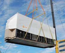
With the FlexFit solution, you receive fast delivery and assembly options that best meet your particular space requirements. Depending on your preference, it can arrive fully preassembled from the factory ready to be installed, or if space is an issue we can ship it disassembled with detailed instructions on how to assemble it on-site.
To simplify and expedite the process even further, you can elect to have a Trane representative on-site to oversee the assembly of the unit.
In addition to the FlexFit solution, Trane provides many installation options to support your scheduling needs.
6
199
The right people for the job
Art meets science in the Trane® Custom Performance Climate Changer™ air handler. We combine expertise and experience with a robust quality assurance process to provide you with the best and most reliable air handler to meet your specific needs.



7
200

© 2016 Trane All Rights Reserved. CLCH-SLB022-EN December 0 9, 2016 We are committed to using environmentally conscious print practices. Ingersoll Rand (NYSE:IR) advances the quality of life by creating comfortable, sustainable and efficient environments. Our people and our family of brands—including Club Car®, Ingersoll Rand®, Thermo King® and Trane®—work together to enhance the quality and comfort of air in homes and buildings; transport and protect food and perishables; and increase industrial productivity and efficiency. We are a $13 billion global business committed to a world of sustainable progress and enduring results ©2015 Ingersoll Rand IR000000 We are committed to using environmentally conscious print practices. ingersollrand.com Scan the code or visit Trane.com/CustomPerformanceAHU to learn more. 201
CGAM air-cooled scroll chiller
Highly efficient, yet extremely quiet


202
The right balance of energy efficiency and quiet operation
High efficiency or low noise? Most air-cooled chillers require you to choose between the two. The new 20 to 130 ton model CGAM air-cooled scroll chiller from Trane gives you the best of both worlds.
A quieter fan often produces less air flow, making it less efficient. The Trane design team compiled the best approaches from around the globe to optimize the Trane CGAM chiller—so that it meets global green initiatives and ASHRAE energy-efficiency standards.
The Trane CGAM chiller is one of the quietest air-cooled chillers, even among screw compressor equipment. Low sound levels are standard, with a 5 to 8 decibel reduction compared to previous

Trane air-cooled chiller models. And with factoryinstalled attenuation, Trane reduces sound levels even further—up to an additional 3 decibels.
Reliability you can count on
You need performance you can count on. As a result, we extensively test on our compressors and units to confirm their robust design.
Trane delivers
• Extreme testing—including cold ambient starts, hot water starts and high ambient operation
• Compressor-accelerated lifecycle testing, including high-pressure ratio, high load test, flooded starts/stops, start/stop testing and phase reversal
• Performance modeling and verification, both during design and for the life of the chiller
• FEA analysis to confirm the unit structure can withstand shipping, rigging and operational activity
• Electrical testing with destructive testing for short circuit withstand rating
To minimize leaks, Trane improved the coil structure by strengthening the coil frame and changing the construction method.
We use a single copper tube for two passes through the coil to reduce braze joints on one side, eliminating up to sixty joints. This new construction method ensures all coils are square, so the coil components are better aligned.
2 CGAM air-cooled scroll chiller
The Trane on-site test facility ensures the reliability and performance of your system.
203
Factory-installed reliability
Several factory-installed features further reduce your energy consumption, add redundancy for mission-critical operations and reduce jobsite installation time—when every day counts.
A factory-installed pump package, designed specifically for this unit, comes pre-wired and factory-tested. The dual pump set-up provides built-in redundancy and the standard inverter delivers added energy savings.
With the factory-installed buffer tank, you can use the chiller in applications with less than a three-minute water loop and still maintain precise temperature control.
The flow switch and water strainer are also factory-installed as standard, reducing job site installation requirements and ensuring reliable operation.
Reduce your energy usage at every point
Using some of the best analytic approaches and tools in the industry, Trane engineers look for ways to reduce energy usage at every point within your system. For example, using partial heat recovery, the heat rejected from the condenser while cooling the building can be redirected through a factory-installed heat exchanger on the chiller to provide heat for VAV reheat coils. This can dehumidify a commercial building more efficiently, or pre-heat laundry or pool water in a hotel.

Another energy-saving strategy is a thermal storage system that uses ice made at night, when energy costs are lowest, to cool the building during the day. Thermal storage can be used in many settings, including schools, government buildings and industrial processes.
One way Trane reduces energy costs is with a thermal storage system design that uses ice made at night, when energy demand and cost are lowest, to cool the building during the day.
3
204
CGAM air-cooled scroll chiller
20-130 Ton
exceed ASHRAE 90.1 standards by 6 to 8%.
Fans—quiet design is standard, 5 to 8 decibels lower than current models, with attenuation options for applications requiring ultra-quiet operation.
Integration—pump package and buffer tank are pre-wired and tested in the factory.
Heat recovery—can provide 140°F (60°C) water to dehumidify buildings or pre-heat laundry or pool water.
installed in an optimal location. Increased coil structure strength and reduced brazed joints control leaks.
Controls—CH530 improved fan staging logic for low ambient starting capability; Adaptive Controls™ are standard to maintain operation in adverse conditions.

Durability—powder-coated components and optional coated coils minimize corrosion.
Serviceability—major components are positioned for easy access. The unit structure is designed to rig pump up for easy seal changes.
4 CGAM air-cooled scroll chiller
205
Controls for reliability, efficiency and system monitoring
Trane unit controls and building automation solutions are designed to meet your critical requirements. Adaptive Control™ algorithms embedded in the factory-mounted CH530 controller on the CGAM chiller use Trane proprietary strategies to respond to normal, extreme or adverse conditions. The sophisticated algorithms intelligently maximize uptime while protecting equipment from damage.
The chiller manages time-of-day scheduling for small buildings or schools without a building automation system. If an integrated pump package is included, the chiller even controls pumps as needed. For larger enterprise-wide projects, a Tracer ES™ building automation system monitors and manages all chillers within the enterprise.
Manage multiple chillers from any location

Adding the Tracer™ SC controller to a system provides a flexible, cost-effective solution for managing your HVAC system that can extend to lighting and energy consumption. Its simplified,
Web-based management tools help improve efficiencies, increase tenant comfort and reduce energy costs.
Accessible from any PC with an Internet connection, Tracer SC eliminates the need for a dedicated computer and monitor, so you can manage system performance whenever, wherever it is convenient. Tracer SC controller’s simplified, Web-based management tool reduces scheduling, reporting and applications programming chores to simple “point and click” tasks. Users do not have to invest in special software or training—so it is easy to control the building without additional costs.
Tracer SC is scalable for most buildings—small, medium or large—and can grow with your building and adapt to your changing needs. With expandable communications from 30- to 60- to 120-unit controllers, it is a flexible and costeffective choice.
Tracer SC now supports BACnet™ top to bottom, as well as existing LonWorks™ controllers.
5 5
206
Tracer SC can manage chiller sequencing and load sensing for optimum control on site or over the Web.
Expert services for the life of your building
Trane Building Services helps you improve energy efficiency, reduce operating costs and enhance the performance of your equipment—making your building work better for life.
CGAM chiller is available with the Trane Elite Start™ suite of services to make sure your system operates as designed from day one. Factory start-up services will help your system perform to specifications upon installation.
Trane recommends these Elite Start services:
• In-Warranty Support—oil analysis, diagnostic reporting and monitoring keep equipment operation at peak performance during the first year of operation
• Extended Warranty—covers parts and labor associated with any equipment failure
• Service Agreements—scheduled inspections for preventive and proactive maintenance ensure long-term reliability, efficiency and performance

Easier to service if needed
We take advantage of the vast knowledge of service professionals by including them in our early design efforts. As a result, the Trane CGAM chiller has many valuable service improvements:
• All major serviceable components are very close to the edge of the unit, making it safer and easier to service. The unit has easy-toreach service valves, water strainer and water piping connections.
Not only do Trane CGAM air-cooled chillers deliver the lowest noise levels and highest efficiencies in their class, but they also can be applied with Trane fan coil units or air handlers to improve indoor air quality — helping achieve LEED® performance.
6 CGAM air-cooled scroll
chiller
207
• Hinged condenser fans with a prop rod makes coil cleaning safer and fan servicing easier.

• The factory-installed pump package is designed to service in place, including pump seal changes. Simply lift the pump within the chiller structure to replace the seal.
• The high-pressure transducer and temperature sensor mountings enable troubleshooting and replacement without refrigerant handling
• Separate access to the low-voltage control panel makes the chiller easier to service

To help ensure that building performance is meeting your business needs, our service professionals tap into a global network of proven best practices, Trane proprietary technology and industry-leading expertise.
We continually train our technicians and provide on-demand access to all the latest resources
to make maintenance decisions that will finetune your entire system, in order to achieve the highest level of performance.
No service provider is more qualified to deliver the cost savings and performance assurance you demand from Trane equipment. Trane sales and service professionals will customize creative solutions that meet your specific maintenance, budget and operational requirements. To minimize any downtime, the Trane nationwide network of HVAC Parts and Supply stores ensures you can get the part you need when you need it.
Contact your local Trane Account Manager to learn more about how you can increase your efficiency without sacrificing quiet operation, enjoy low lifecycle costs and gain the peace of mind a Trane chiller provides.

7
208
Get help making the right decision

There are hundreds of possible system designs and chiller configurations, and thousands of possible efficiency levels. How do you determine the right HVAC system for your building?
Whether you are calculating energy efficiency to determine eligibility for LEED credits, earn tax deductions, or select the HVAC system with the lowest operating costs, Trane can help. The Trane System Analyzer™ software estimates building loads and performs preliminary energy and economic analyses of virtually any building, system and equipment combination.
For LEED certification, TRACE™ 700 (Trane Air Conditioning Economics) software helps analyze the energy and economic effects of virtually any system by letting you manipulate a wide range of variables to create a detailed energy usage profile for the specific building. Unlike overly simplified spreadsheet-based energy analysis, TRACE 700 software accurately compares the impact of building alternatives, such as architectural features, HVAC systems and other economic options, to provide true lifecycle, costbased decisions.
Ingersoll Rand (NYSE:IR) is a world leader in creating and sustaining safe, comfortable and efficient environments in commercial, residential and industrial markets. Our people and our family of brands—including Club Car®, Hussmann®, Ingersoll Rand®, Schlage®, Thermo King® and Trane®— work together to enhance the quality and comfort of air in homes and buildings, transport and protect food and perishables, secure homes and commercial properties, and increase industrial productivity and efficiency. We are a $14 billion global business committed to sustainable business practices within our company and for our customers.
©
Trane All rights reserved
CG-SLB017-EN March 23, 2011 ingersollrand.com Produced on post-consumer
environmentally friendly print
reduce waste.
2011
trane.com
recycled paper, using
practices that
209
Your local Trane Account Manager can help you find the CGAM chiller to meet your building’s specific cooling needs.
BENEFITS
Global Plasma Solutions’ technology is easily added to any forced air heating and cooling system. With most installations taking 15 minutes or less, GPS is the contractor’s first choice and the end users best solution for achieving exceptional IAQ due to all of the benefits the GPS-2400 technology provides. Below is a short list of the many benefits the GPS-2400 plasma output provides:

Odor Control

Mold Control


Virus Control
Bacteria Control
Allergen Control*


Easy Installation
LED Operation Light
No Replacement Parts
Particulate Reduction

Static Electricity Control

Low Power Consumption
Essentially No Maintenance
ETL Listed for Electrical Safety


0.00 PPM Ozone Per UL 867-2007 chamber test
*Based on testimonials by actual customers
CUSTOMERS
Global Plasma Solutions
LimitlessApplications Distributed By: 714 Mall Blvd., Suite 3 Savannah, GA 31406 Phone: (912) 356-0115 Fax: (912) 356-0114 Email: sales@gpshvac.com Web: www.gpshvac.com Global Plasma Solutions SAVING ENERGY. SAVING LIVES™
GPS-2400
Plasma has many benefits. GPS’ technology produces natural, friendly, oxidizers that seek out contaminants and odors in the space. The plasma, when produced and injected into a moving air stream, breaks down gases to harmless compounds prevalent in the atmosphere such as oxygen, nitrogen, water vapor and carbon dioxide. In addition to the reduction of gases and odors, plasma also reduces particulates and kills mold, bacteria and virus in the space.
GPS’ Plasma Reduces Airborne Particles
The plasma clusters are drawn to airborne particles by their electrical charge. Once the cluster is formed around the particle, the particle grows larger by attracting nearby particles and increases the filtration effectiveness.

Plasma Kills Virus, Bacteria and Mold - In the Space!

Plasma travels with the air flow and surrounds the pathogens (See Figure 1), confirmed by EMSL Labs. Next, the plasma robs the pathogens of the hydrogen necessary for them to survive (See Figure 2). During the final step, the plasma eliminates hydrogen from the pathogen and then the cleansing process is complete, making the airborne virus, bacteria or mold spore inactive (See Figure 3).

ACTUALSIZESHOWN
Voltage: 24VAC,115VAC,208-277VAC
Power: 2.5VA
Capacity: 100 CFMto2,400CFM
Size: 2.4”Hx1.2”Dx1.7”H
Weight: 0.25lbs
-FanCoils

-HeatPumps

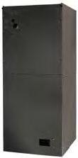

-GasFurnaces
-ChilledBeams
-DuctlessSplits


-CeilingCassettes
-PTACS


-UnitVentilators
-AirHandlers
DidyouknowGPS’independenttestingshows ColdPlasmakills99.6%of contaminants inlessthan15minutesinthespace?
H1N1 FelineCoronavirus

H5N1 CoxsackieVirus
MRSA PolioVirus
STAPH SARSVirus
e.Coli SerratiaBacterium(TB)
Your
Health
What Can Plasma Do For You? GPS-2400 IAQ Affects
Family’s
Figure 1
Figure 2 Figure 3
The GPS-2400 Fits Inside Any System!
HIGH-EFFICIENCY AIR FILTERS
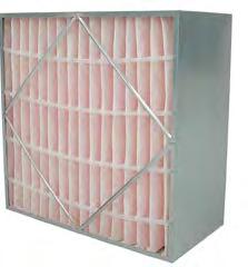
HERE’S A QUICK LOOK AT THE TYPES OF HIGH-EFFICIENCY AIR FILTERS AND HOW THEY ARE USED.
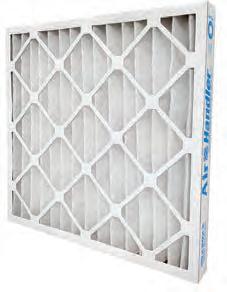
HIGH-EFFICIENCY PLEATED FILTERS
MERV ratings from 11-14.
These are the standard when it comes to most HVAC systems, because they are easy to install, come in standard sizes and have a low initial cost.
ADVANTAGE:
Energy Efficient and Environmentally Friendly
WHERE THEY ARE USED:
Commercial, healthcare, municipal, government, hospitality and residential
POCKET FILTERS
MERV ratings up to 14.
Also referred to as bag filters, pocket filters are constructed of a plastic or galvanized steel frame and contain fiberglass or synthetic media. They are called pocket filters because the media is stitched or sonically welded to form pockets ranging from 10 to 36 inches deep.
ADVANTAGE:
Long Service Life
WHERE THEY ARE USED:
Commercial, educational, healthcare, government and manufacturing
WHAT IS MERV?
RIGID CELL FILTERS
MERV ratings from 11-14.
These filters come in a box-style format and contain either synthetic media or fiberglass. Rigid cell filters look similar to pleated filters but have a depth of 6-12 inches and are surrounded by a galvanized metal or plastic frame.


ADVANTAGE:
Durability
WHERE THEY ARE USED:
Commercial and industrial HVAC systems, VAV systems, high-humidity applications, clean rooms, healthcare, food service and manufacturing
HEPA FILTERS
Not MERV rated because they must offer efficiency of at least 99.97% and up to 99.99% of airborne particles 0.3 microns in size to qualify as HEPA.
ADVANTAGE:
Highest Efficiency
WHERE THEY ARE USED: Clean rooms, medical facilities, laboratories, airplanes, commercial, industrial, residential
MERV stands for the Minimum Efficiency Reporting Value of a filter. It is a method of stating the efficiency of a filter based on particle size and is determined by testing the performance of the filter when exposed to particles of a known size in the air stream.
MERV can be used as a guide to selecting filters for specific contaminants within a range of particle sizes.
Control These Contaminants: 1.0-3.0 Micron Particle Size Legionella, Lead Dust, Humidifier Dust, Coal Dust, Nebulizer Dust
Applications:
Control These Contaminants:
<_0.30 Micron Particle Size Virus (Unattached), Carbon Dust, Sea Salt, All Combustion Smoke, Radon Progeny
Applications: Hospital Patient Care, General Surgery, Smoking Lounges, Superior Commercial Buildings 17-20
Applications: Cleanrooms, Radioactive Materials, Carcinogenic Materials, Pharmaceutical Manufacturing, Orthopedic Surgery

BEST FILTER FOR THE JOB
higher
sometimes
can
cut
on energy use and may
the
article
1. http://www.grainger.com/tps/air-handler-high-filtration.pdf 2. http://www.mechreps.com/PDF/Merv_Rating_Chart.pdf 3. http://www.nafahq.org/pressure-drop-considerations-in-air-filtration/ 4. Filters and Filtration Handbook by Kenneth S. Sutherland 5. http://www.ultravation.com/news/2013/01/17/what-is-pressure-drop/ 6. Life Cycle Costing of Air Filtration By B. Dean Arnold, Member ASHRAE; David M. Matela; and Alan C. Veeck, Member ASHRAE 7. http://www.engineersedge.com/filtration/hepa_filter.htm 8. http://www.epa.gov/epp/pubs/about/about.htm#a GET THE Sources: The following sources were consulted to create this Infographic Copyright © 2014. W.W. Grainger, Inc. W-WEXE716 GRAINGER.COM | 1-800-GRAINGER 1-4 Control These Contaminants: >10.0 Micron Particle Size Pollen, Dust Mites, sanding dust, textile/carpet fibers Applications: Minimum Filtration, Residential furnaces, window air conditioners 5-8 Control These Contaminants: 3.0-10.0 Micron Particle Size Mold, Spores,
A
efficiency filter, while
more expensive,
help
down
also require less maintenance. Read
full
here.
Dusting Aids, Cement Dust
Commercial
Industrial
Building, High End Residential,
Work Spaces, Paint Booth Inlet Air 9-12
Applications: High-End Residential, Commercial Buildings, Hospital Laboratories 13-16 Control These Contaminants: 0.30-1.0 Micron Particle Size All Bacteria, Tobacco Smoke, Sneeze Nuclei, Most Smoke, Insecticide Dust, Copier Toner, Face Powder
212
TF Therma-Fuser™
SquareThermally Powered VAV Diffuser

Models: TF-HC Separate set points for VAV heating and VAV cooling
TF-HC-LH A TF-HC with maximum flow limited in heating only
TF-CW One set point for VAV cooling with warm up
TF-C One set point for VAV cooling only
BENEFITS AT A GLANCE.
INDIVIDUAL COMFORT SELECTION AND CONTROL
Every Therma-Fuser™ diffuser is a VAV zone of temperature control providing pleasing comfort in both heating and cooling. The built in thermostat senses average room air temperature from a sample of air induced into the unit. It controls air flow to precisely match the comfort requirements of the room or portion of the room served. Occupants breathe easier knowing that their personal temperature choice will not be changed by someone else.
LIMITED HEAT & NO HEAT
The ASHRAE Standard 90.1 requires controls in an HVAC system that limit the reheating of air that was previously cooled. Use the LIMITED HEAT option to meet the ASHRAE standard.
The TF-LIMITED HEAT has an adjustable mechanical stop that will limit maximum flow to the required percentage only in the heating mode.
For applications, such as a computer room, where cooling loads always exist but the supply may at times be heated, there is a NO HEAT option. When the supply air is warm, the TF-NO HEAT will close and not open regardless of the room temperature.
ONLY THERMA-FUSER™ VAV OFFERS THESE BENEFITS
• Separate temperature set points for VAV heating and VAV cooling.
• Superior air distribution— longer throws, no dumping, more entrainment, even temperature distribution, higher ADPI* and better room air change effectiveness.
• Lowest cost per zone of control.
• Lowest energy VAV terminal— green VAV.
• Low to no maintenance— 10 year warranty.
• Easily adapts to office changes.
Therma-Fuser™ Systems
TF: Product Overview FORM 041.101 REV 1008
*ADPI (Air Diffusion Performance Index) 213
HOW IT WORKS
Model TF Therma-Fuser diffusers are 24” (600mm) square ceiling diffusers with built in temperature controls and VAV damper. Four blade dampers move up to close and down to open, metering air flow (warm or cool) into the room in response to room temperature. The dampers are mechanically positioned by thermostat/actuators which are both a room thermostat and damper motor. The room thermostat/actuators are a large brass cylinder containing a petroleum based wax. The wax melts and expands when heated, driving a piston out. A spring retracts the piston when the wax cools and contracts. The movement of the piston positions the dampers in a proportional manner.
ROOM AIR SENSING
As with all diffusers, air circulates around the room in a circular motion. Secondary air rises under the diffuser, passes beneath the appearance panel and entrains with the primary air at the outside edge of the diffuser (fig.1). This secondary air best represents average room temperature.
To monitor average room temperature, a continuous sample of secondary air is drawn around the appearance panel past the room thermostats. This is accomplished by feeding primary air through four venturi nozzles. Primary air blowing through the nozzles creates just enough vacuum to draw some secondary air around the appearance panel, over the thermostats and out the other side. A properly applied TF will hold the room average within 1.5˚F/0.9˚C of the temperature selected.
COOLING MODE
In the cooling mode the dampers open on a rise in room temperature. As the room warms, the wax in the room thermostats melts and expands. This pushes the cooling thermostat piston outward against the control plate. The control plate then pivots around the center bearing, opening the dampers allowing more supply air to enter the room. When the room cools, the wax contracts, a spring retracts the cooling thermostat piston and a spring returns the control plate closing the dampers.
CHANGEOVER
(TF-HC and TF-CW ONLY)
Changeover between the cooling and heating modes is determined by supply air temperature. A thermostat/actuator located in the inlet of the diffuser senses supply air temperature. Warming the changeover thermostat changes the TF to the heating mode by pivoting the control plate over center. As a result the cooling thermostat is disengaged and the heating thermostat engaged.
Changeover from cooling to heating begins at supply air temperature 76°F/24.5°C and completes at 80°F/26.5°C. Changeover back to cooling begins at 72°F/22°C and completes at 68°F/20°C. During changeover the damper is closed or at minimum flow. The control plate pivots over center, first closing the damper and then opening it.
HEATING MODE
(TF-CW ONLY)
In the heating mode, the dampers are fully opened and will remain fully opened until the diffuser changes back from heating to cooling mode.
HEATING MODE (TF-HC ONLY)
In the heating mode, the dampers open on a drop in room temperature. As the room cools, the wax in the room thermostats contracts. A spring retracts the piston in the heating thermostat allowing a spring to pivot the control plate, opening the dampers allowing more supply air into the room.
ADJUSTING SET POINTS
Heating and cooling set points are separately adjusted by turning the heating and cooling thermostats (fig.2). Align the white indicator on each thermostat with its respective temperature scale. Each set point can be anywhere between 70°F/21°C and 78°F/25.5°C. Both are factory set at 74°F/23°C. (The model TF-CW and TF-C have only a cooling thermostat).
OPEN FOR BALANCING
To open, unhook the tension spring from the bracket adjacent to the cooling thermostat and turn the control plate slightly to drop the dampers open (fig.3).
MINIMUM FLOW
To drive room air sensing, primary air is continuously supplied through the four venture nozzles even when the dampers are closed. The nozzles supply approximately 35cfm/16l/s at 0.15”wg/37Pa (fig.4). If required, additional minimum flow is available for both fixed and adjustable flow stops (see Options).
SYSTEM DESIGN
The best control for heating/cooling units supplying air to VAV terminals is a discharge thermostat which maintains a constant supply air temperature. With DX equipment these are a high and low limit. Use a room thermostat for changeover between heating and cooling modes. For hybrid systems (part VAV and part constant volume) control the heating/ cooling supply unit with a thermostat in one of the rooms with a constant volume diffuser, preferably the space with the greatest load. For both VAV and hybrid systems, the fan should run continuously. The constant discharge velocity of Therma-Fuser diffusers at varying air flow provides good room circulation
Diffusion Dampers Control Plate Appearance Panel Room Temperature Sensing Thermostats Venturi Nozzle Changeover Thermostat fig.1 NECKSECT I O N
Inlet Designation 6 8 10 12 Inches ± 1/16 5 15 / 16 7 15 / 16 9 15 / 16 11 15 / 16 mm ± 3 150 200 250 300 OD DIMENSIONS TF Therma-Fuser ™ Square Thermally Powered VAV Diffuser
*595±2mm Square with 16±2mm lip available —specify 595mm square.
2 214
which reduces stratification. Keeping heating supply air temperatures as low as possible will further reduce room air stratification to a negligible level.
Static pressure at the inlet of the ThermaFuser diffuser should be between .05"wg/12Pa and .25"wg/62Pa, at full and partial air flows. Static pressure below .05"wg/12Pa will result in low air flow and less induction. Above .25"wg/62Pa, ThermaFuser diffusers operate well but excessive noise may result. Use minimum flow settings where tight shut off is not needed. If the system turns down more than 30%, static pressure should be controlled. Included in the options for static pressure control are fan speed control and modulating bypass dampers. Modulating zone dampers are recommended where several zones share a higher pressure duct or riser.
When designing ducts, if Therma-Fuser diffusers are to deliver nominal volume at inlet SP of .15"wg/37Pa and if a maximum SP of .25"wg/62Pa is to be held for quiet operation, size the duct for a maximum pressure drop of .1"wg/25Pa between the first and last takeoff.
Manual balancing dampers should be used at the takeoff for each diffuser. Manual balancing dampers may not be required with ducts designed to Acutherm specifications.
Because Therma-Fuser diffusers control room temperature by sensing room air induced up the center of the space, care should be taken not to disturb room air induction and entrainment. For example, location next to walls or dropped lights results in the reflection of primary air back at the Therma-Fuser diffuser. Relocate either the Therma-Fuser diffuser or the light. Acutherm has “how to” system design brochures for almost every ducted air system. For specific recommendations refer to the brochure for your system.
GUIDE SPECIFICATION
(Suitable for Section 23 36 16 Variable-AirVolume Units of the CSI MasterFormat). MaterialinitalicsappliesonlytomodelTF-HC. Delete the italics forTF-C andTF-CW.
2.2 Thermally Powered VAV Diffusers
A. Thermally powered variable air volume diffusers shall be Therma-Fuser™ model TF manufactured by Acutherm, Hayward CA.
B. Thermally powered VAV diffusers shall be a complete VAV terminal and thermostat self-contained in a nominal 24” (600mm) square diffuser. They shall be thermally powered with one cooling thermostat/ actuator, oneheatingthermostat/actuator andonechangeoverthermostat/actuator. External wiring or pneumatics shall not be allowed.
• Denotes 750 fpm / 3.81 m/s inlet velocity.
* Throw data is for air 20°F/11°C lower than room temperature. Throws for isothermal air are 40 to 50% greater.
† NC based on Lw(10-12 watts reference) -10db - Metric performance guide available on request.
- Tested in accordance with ANSI/ASHRAE 70, ANSI S12.31, ARI 890, ISO 5219 and ISO 3741. - When using Acutherm directional baffles for other than four way blow patterns, reduce the maximum air volume as shown in Acutherm Form 12.2.
C. The VAV diffusers shall have a micrometer type temperature set point adjustment with an indicator and temperature scale to adjust the cooling set point andaseparatemicrometer typetemperaturesetpointadjustment withanindicatorandtemperature scaletoadjusttheheatingsetpoint. The adjustment shall be right above the hinged appearance panel and shall not require tools. Each set point shall be separately adjustable between 70°F/21°C and 78°F/26°C. The initial set point shall be factory set at 74°F/23°C.
D. In the cooling mode the VAV diffusers shall open on a rise in room temperature andintheheating modetheyshallcloseonarisein roomtemperature.Thechangeover thermostatshallbefactoryinstalled andadjustedtoengagetheheating modewhenthesupplyairtemperature rises above 80°F/27°C and return to thecoolingmodewhenthesupplyair temperaturefallsbelow68°F/20°C. Duringchangeoverthediffusershall closeor,ifaminimumflowisset,go to the minimum. Nothing, includingthe changeovermechanism, shall extend above the inlet of the diffuser.
E. The VAV diffusers shall have four perimeter dampers to provide 66 linear inches of variable discharge area at the perimeter of the diffuser for maximum Coanda effect and to avoid dumping.
F. All VAV diffusers shall have a solid (no holes or slots) hinged appearance panel that can be unlatched and folded down to hang allowing hands to be free for adjusting temperature set points. Instructions for the VAV diffuser shall be on the inside of the appearance panel.
G. The VAV diffusers shall have positive induction of secondary room air over the thermostat at all flows from fully closed to fully open.
H. The VAV diffusers shall have a single spring disconnect which will open the dampers for balancing without tools. VAV diffusers requiring tools, adjustment of set points or adjustment of supply air temperature to open for balancing shall not be allowed.
I. All VAV diffusers shall warrant that the diffuser shall be free from defects in materials and workmanship for a period of ten years from date of shipment.
Temperature set point indicator (white) 21 C 70 F 24 C 74 F 26 C 78 F fig.2 Adjusting Set Points Nozzles (blue) Tension Spring for Balancing
Nomimal Inlet Diameter Inlet Static Pressure In. wg Maximum Flow cfm Maximum Flow 25% Maximum Flow Throw - Feet* @ vt=50/100/150FPM †NC Throw* - Feet @ vt=50/100/150FPM †NC 6" .05 100 6/4/3 <15 3/2/1 <15 .10 140 8/5/4 20 4/3/2 17 •.11 147 8/5/4 21 4/3/2 18 .15 175 9/6/5 26 5/4/3 21 .20 200 9/7/6 31 6/5/3 24 .25 220 10/8/7 34 7/6/4 27 8" .05 160 8/6/4 <15 5/3/2 <15 .10 225 10/7/5 20 6/4/3 16 •.13 255 11/8/6 23 7/5/3 19 .15 275 11/8/6 25 7/5/3 21 .20 320 12/9/7 30 8/6/4 25 .25 355 13/10/8 34 9/6/4 28 10" .05 260 9/7/5 15 7/6/4 <15 .10 370 11/8/6 23 9/7/5 18 •.12 402 12/9/7 25 9/7/5 20 .15 450 13/10/8 27 10/8/6 22 .20 520 14/11/9 31 11/9/7 26 .25 580 15/12/10 34 12/10/7 29 12" .05 350 11/8/6 15 7/6/4 <15 .10 470 13/10/8 23 9/7/5 19 .15 560 15/12/10 27 10/8/6 23 •.16 576 15/12/10 28 10/8/6 24 .20 640 16/13/11 31 12/10/8 27 .25 720 17/14/12 34 14/11/9 30
fig.3 fig.4
PERFORMANCE GUIDE
-
When using Acutherm R-Rings, throws may be as low as 90% and NC 2db higher than those listed in the performance guide.
3 215
TF Therma-Fuser ™ Square Thermally Powered VAV Diffuser

TEN YEAR WARRANTY
Acutherm warrants that its TF diffuser, exclusive of any options and accessories (whether factory or field installed) shall be free from defective material or workmanship for a period of ten (10) years from the date of shipment and agrees to repair or replace, at its option, any parts that fail during said ten (10) year period due to any such defects which would not have occurred had reasonable care and proper usage and all parts and controls remain unaltered. Acutherm makes NO WARRANTY OF MERCHANTABILITY OF PRODUCTS OR OF THEIR FITNESS FOR ANY PURPOSE OR ANY OTHER EXPRESS OR IMPLIED WARRANTY WHICH EXTENDS BEYOND THE LIMITED WARRANTY ABOVE. ACUTHERM’S LIABILITY FOR ANY AND ALL LOSSES AND DAMAGES RESULTING FROM DEFECTS SHALL IN NO EVENT EXCEED THE COST OF REPAIR OR REPLACEMENT OF PARTS FOUND DEFECTIVE UPON EXAMINATION BY ACUTHERM. IN NO EVENT SHALL ACUTHERM BE LIABLE FOR INCIDENTAL, INDIRECT OR CONSEQUENTIONAL DAMAGES OR DAMAGES FOR INJURY TO PERSONS OR PROPERTY. Acutherm shall not be responsible for freight to or from its plant in connection with the inspection, repair or replacement of parts under the terms of this limited warranty nor for cost of removal or installation. Protected by U.S. Patents 6,736,326 & 6,857,577. Patents pending in other countries.
Use
Product
1.Model: TF – Square Therma-Fuser diffuser
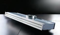
2.Type: C VAV cooling only, CW VAV cooling with warm up, HC-NH VAV cooling with no heat, HC VAV heating and cooling, HC-LH VAV heating and cooling with limited heat.
3.Size: 6, 8, 10, or 12 inch inlet
Options
1. Remote Adjust: DA1 or DA1M for Digital Wall Adjuster

2.R-Ring: Rx for bypass relief ring where ‘x’ is 6, 8 or 10" inlet
3.Insulation: I for attic side insulation
4.Security Hanger: H
5.Minimum Flow: FR rubber type, FS screw type
6.Sheared Housing: 595 for 600mm metric grid ceilings, T1 for 233/16” and T2 for 223/4”
7.Blow Patterns: TFD3 for 3-way blow, TFD2C for 2-way blow corner, TFD2 for 2-way blow opposite, and TFD1 for 1-way blow.
8.Silk Screen: S for appearance panel pattern
9.Sensor: SMCS for SMC or SENSOR for 3rd party
Accessories
1.Ceiling Frame: TFHD for hard ceiling, TF4DB for 4” drop box, TF1DB for 17/16” drop box, TFSP for spline, TFT1 for tegular 9/16” T-bar, TFT2 for tegular 1” T-bar, and TFAL for air lifter (no ceiling)
Send

PRODUCT INFORMATION DESCRIPTION
model number nomenclature
Therma-Fuser diffusers,
Product (1) Ceiling Frame (1) Model TF (2) Type (3) Size Options (1) Remote Adjust (3) Insulation (2) R-Ring (4) Security Hanger (5) Minimum Flow Accessories (6) Sheared Housing (8) Silk Screen (7) Blow Patterns (9) Sensor Square VAV Diffusers Round VAV Diffusers Linear VAV Diffusers Accessories Pressure Control Temperature control Square VAV Diffusers Round VAV Diffusers Linear VAV Diffusers Accessories Pressure Control Temperature control ©2010 Acutherm FORM 041.101 REV 1008
PRODUCT GUIDE ACUTHERM HEADQUARTERS 1766 Sabre Street Hayward CA 94545, USA Tel: +1 510 785 0510 Fax: +1 510 785 2517 AVAILABLE ONLINE Access digital brochures, CAD files, performance data and more! www.acutherm.com CALL US Talk to our customization and specification experts +1 800 544 1840 EMAIL SUPPORT
the following
to order
options and accessories.
ACUTHERM
us your questions and we’ll get you the answers you need.
info@acutherm.com
216
217
Exhibit B Judiciary's Propoposed Budget FY 2017

219
Exhibit C Public Law 20-61
RALPHDLG.TORRES Governor

The Honorable Rafael S. Demapan Speaker, House ofRepresentatives
Twentieth Northern Marianas Commonwealth Legislature
Saipan, MP 96950
The Honorable ArnoldI. Palacios Senate President, The Senate
Twentieth Northern Marianas Commonwealth Legislature


Saipan, MP 96950
Dear Mr. Speaker and Mr. President:
This is to inform you that I have signed into law House BillNo. 20-164, HD3, SD1, CCS 1 entitled, "To appropriate fifteen million dollars ($15,000,000) from the Special Casino Gross Revenue Tax Account, earmarked under 4 CMC §2308.", which was passed by the House of Representatives and the Senate ofthe Twentieth Northern Marianas Commonwealth Legislature.


This bill becomes PublicLawNo.20-61. Copies bearing my signature are forwarded for your reference.
cc: Lt. Governor; Press Secretary; Attorney General's Office; Secretary of Finance; Supreme Court of the Northern Marianas. Marianas Visitors Authority; Mayor of Rota; Commonwealth Utilities Corporation; Rota DPS Academy; CHCC Chief Executive Officer; Northern Marianas Trade Institute; Micronesian Legal Services; Chairman, Rota Municipal Scholarship; Department ofPublic Works; Mayor of Tinian; Docomo Pacific; ; Special Assistant for Administration; Special Assistant for Programs and Legislative Review
CUMMUNWEALflIof theNUR!l!EHN.MARJAN.A!Sl.Al'.'DS
OFFICEOFTHEGOVERNOR
.1 '5 JUN 2018
VICTORB.HOCOG Lieutenant Governor
s
CNMI Office of the Governor Juan A. Sablan Memorial Building Capitol Hill, Saipan Caller Box 10007 Saipan, MP 96950 n (670) 237-2200 I Facsimile: (670) 664-2211 I www.gov.mp 11 Ralph DLG. Torres CNMI Office of the Governor 220
Jfouse of<Rspresentatives
201hNORTHERNMARIANASCOMMONWEALTHLEGISLATURE
P.O. BOX 500586
SAIPAN, MP 96950
June 13, 2018
The Honorable Ralph DLG. Torres
Governor
Commonwealth of the Northern Mariana Islands

Capitol Hill
Saipan, MP 96950
Dear Governor Torres:
I have the honor of transmitting herewith for your action H.B.No. 20-164, HD3,SDI,CCSI, entitled: "To appropriate fifteen million dollars ($15,000,000) from the Special Casino Gross Revenue Tax Account, earmarked under 4 CMC §2308.", which was passed by the House of Representatives and the Senate ofthe Twentieth NorthernMarianas Commonwealth Legislature.

Sincerely yours,
Attachment

PublicLawNo. 20-61
/
ed
House.£l
221
rr'wentietli Legisfature of tlie
Commonwea{tfi oftlie :Nortliem :Mariana Isfancfs

IN THE HOUSE OF REPRESENTATIVES
FIRST SPECIAL SESSION
APRIL 24,2018
REPRESE:\TATl\'E ANGEL A. OE:\tAPAN of Saipan, Precinct I (jorhimself, Representatives Blas Jonathan "BJ" T. Attao, Lorenzo I. Deleon Guerrero, Rafael S. Demapan, and John Paul P. Sablan,) in an open and public meeting with an opportunity for the public to comment, introduced the following Bill:
H.B. No. 20-164, HD3, SDI, CCSl ANACT

1'0 Al111ll0PIUA1'E l�Il�'l'EEN �111..1..ION DOf..l.J\llS ($15,000,000) 1�uo11 'l'IIE SPECIAi.. (;ASINO GllOSS llE\'ENUE 'l'AX A(;(;OUN'l', EAlllIAllliEI) UNHEll 4(;�IC §2!JOU.
The Bill was not referred to a House Committee.
THEBILL WAS PASSED BY THE HOUSE OF REPRESENTATIVES ON FIRST AND FINAL READING, APRIL 24, 2018; withamendments in the fonn of H . B . 20-164,HDJ and transmitted to the THE SENATE.


The Bill was not referred to a Senate Committee. THE BILL WAS PASSED BY THE SENATE ON FIRST AND FINAL READING, APRIL 27, 2018; withamendments in the form of H. B. No. 20-164,HDJ,SDI 1-1. B. No. 20-164,HDJ,SDI, was returned to the House of Representatives on April 27,2018.
The House of Representatives rejected the Senate amendments and the Bill was sent to Conference, which submittedConference Committee Report No. 20-3.
THE BILL WAS FINALLY PASSED ON JUNE 12,2018.
HouseClerk
PublicLawNo. 20-61
222
CJ'wentietfz Legisfature ofthe
Commonwea{tfz ofthe Wortfzem �ariana Isfancfs
IN THE HOUSE OF REPRESENTATIVES
FIRST DAY, FOURTH SPECIAL SESSION
JUNE 12, 2018
H.B. No. 20-164, HD3, SD1, CCS1
'l'O APPUOPIUA'l'E l�Il�'l'EEN )Jll.I..ION IHH.JJ.\llS ($15,000,000)
l�UO)I 'l'IIE SJ>ECIAI. CASINO GllOSS llE\TENUE 'l'AX A(�COUN'I', EAll)IAllf{EI) UNl>Ell Li (�)IC §2:JOH.
BeitenactedbytheTwentiethNorthernMarianasCommonwealth Legislature:
Section 1. Findings and Purpose. The Governor has advised both houses of the
2 Legislature by letter dated April 13, 2018, identified as House Governors Communication 20-

3 195, that fifteen million dollars ($15,000,000) is available for appropriation. Also provided
4 was a Certification of Fund Availability from the CNMl Department of Finance from the
5 collection of the Saipan Casino Operator's Business Gross Revenue Tax.
6 The purpose of this Act is to appropriate fifteen million dollars ($15,000,000) from
7 the Special Casino Gross Revenue Tax Account, earmarked under 4 CMC §2308.
8
Section 2. Appropriation. Notwithstanding 4 CMC §2308, the amount of fifteen
9 million dollars ($15,000,000) from the Special Casino Gross Revenue Tax Account,
10 earmarked under 4 CMC §2308, is hereby appropriated as follows:

Public Law No. 20-61
ANACT
223
HOUSE BILL 20-164,HD3,SDl, CCS1
(a) Seven million dollars ($7,000,000) for the removal and remediation of mold and the rehabilitation, relocation costs, and procurement of a new air conditioning system for the Guma' Hustisia limwal Aweewe. The expenditure authority of the funds appropriated under this subsection shall be the Secretary of Finance in consultation with the Chief Justice.
(b) Three million dollars ($3,000,000) for land taking compensation. The funds appropriated under this subsection shall be used for land taking compensation of beach parks/recreational areas, secondary roads, and other land takings as certified by the Office ofthe Attorney General based on the following:

(1) Any outstanding land taking compensation up to $40,000 shall be paid in full; and
(2) The expenditure authority of the funds appropriated under this subsection shall be the Secretary of Finance in consultation with the Attorney General.
(c) Two million four hundred thousand dollars ($2,400,000) for the following:
(1) $1,200,000 for the First Senatorial District to fund the following:
(A) $150,000 for the renovation of the Rota Pinatang Beach Park under the expenditure authority of the Mayor of Rota in consultation with the Marianas Visitors Authority Managing Director;
(B) $150,000 for the salaries of the existing municipal employees under Business Unit 7174Y. There shall be no new hires. The Mayor of Rota shall be the expenditure authority;
2 3 4 5 6 7 8 9 10 11 12 13 14 15 16 17 18 19 20 21 22 Public Law No. 20-61
2 224
HOUSE BILL 20-164,HD3�SD1, CCS1
(C) $200,000 for the construction of a concrete wall to secure the Rota water cave area under the expenditure authority of the Commonwealth Utilities Corporation Rota Resident Director;
(D) $265,000 for the Rota medical subsistence allowance under the expenditure authority ofthe Secretary of Finance:
(E) $55,000 for the Rota DPS Academy of the ongoing cycle to pay for operation, gears, and supplies under the expenditure authority ofthe Rota DPS Resident Director:
(F) $50,000 for the Rota interisland medical referral air transportation costs under the expenditure authority of the CHCC Chief Executive Officer;
(G) $120,000 for the interisland medical referral patient and escort stipend under the expenditure authority of the CHCC Chief Executive Officer:
(H) $75,000 for the Northern Marianas Trade Institute (NMTI) programs for Rota students' tuition, fees, and course-related supplies, under the expenditure authority of the NMTI President;
(I) $35,000 for the Micronesian Legal Services Corporation (MLSC) extension program on Rota under the expenditure authority of the MLSC Director; and
(.I) $100,000 divided equally so that $50,000 is for the Rota students housing allowance attending postsecondary schools and

1 2 3 4 5 6 7 8 9 10 11 12 13 14 15 16 17 18 19 20 21 22 Public Law No. 20-61
3 225
H<>USE BILL 20-164,HD3,SD1, CCS1

1 $50,000 for the Rota Municipal Scholarship Program under the
2 expenditure authority ofthe Rota Municipal Scholarship Chairman.
3
(2) $1,200,000 for the Second Senatorial District to fund the
4 following:
5
(A) $1,000,000 for the improvement and pavement of roads at
6 Marpo Heights II sub-division on the island of Tinian. The Secretary
7 of the Department of Public Works shall be the expenditure authority
8 ofthe funds in consultation with the Mayor of Tinian and Aguiguan:
9
(B) $90,000 for ten (10) FTEs under the Department of Public
10 Safety- Tinian for the last two quarters of FY 2018 under the
11 expenditure authority ofthe Mayor of Tinian and Aguiguan:
12
(C) $60,000 for the procurement of one (1) van for the Office
13 of Aging under the Department of Community and Cultural Affairs-
14 Tinian under the expenditure authority of the Mayor of Tinian and 15 Aguiguan;
16
(D) $25,000 for the procurement of one (1) vehicle for the 17 Division of Building Safety under the Department of Public Works18 Tinian under the expenditure authority of the Mayor of Tinian and 19 Aguiguan; and
20
(E) $25,000 for the procurement of one (I) vehicle for the 21 Department of Finance-Tinian under the expenditure authority of the 22 Mayor of Tinian and Aguiguan.
Public LawNo. 20-61
4 226
HOUSE BILL 20-164, HD3, SD1, CCSl

(d) One hundred sixty five thousand dollars ($165,000) shall be used to pay
2 Docomo Pacific, Inc. as the CNMI Government's cost share for the installation and
3 operation of a new fiber network on Tinian as referenced in the Memorandum of
4 Understanding between the Government of the CNMI and Docomo Pacific, Inc. dated
5 March 10, 2016. The Secretary of Finance shall be the expenditure authority for the
6 funds appropriated under this section.
7
(e) Six hundred fifty thousand dollars ($650,000) shall be used to pay Docomo
8 Pacific, Inc. as the CNMI Government's cost share for the installation and operation
9 of a new fiber network on Rota as referenced in the Memorandum of Understanding
10 between the Government of the CNMI and Docomo Pacific, Inc. dated March 10,
11 2016. The Secretary of Finance shall be the expenditure authority for the funds
12 appropriated under this section.
13
(f) Seven hundred thousand dollars ($700,000) for the rehabilitation and
14 improvement of Sugar Dock including architectural and engineering design. The
15 Secretary of the Department of Public Works shall be the expenditure authority for
16 the funds appropriated under this subsection.
1 7
(g) One million eighty five thousand dollars ($1,085,000) for the architectural
18 and engineering design, and construction of a solid waste transfer station at the
19 southern part of Saipan. The Secretary of the Department of Public Works shall be
20 expenditure authority of the funds appropriated under this subsection.
21 Section 3. No Fiscal Year Limitation and No Reprogramming. Notwithstanding
22 any laws, provisions or regulations to the contrary, the funds appropriated under Section 2 of
Public Law No. 20-61
5 227
HOUSE BILL 20-164,HD3,SD1, CCSl
1 this Act shall not be reprogranuned for any other purpose and all the funds shall be available
2 for expenditure without fiscal year limitation.
3 Section 4. Reporting Requirement. The expenditure authorities of the foregoing
4 activities listed in Section 2 of this Act shall submit to the presiding officers of the
5 legislature, within 30 days after the end of each quarter, a fund status report on the
6 expenditure of funds.
7 Section 5. Severability. If any provisions of this Act or the application of any such
8 provision to any person or circumstance should be held invalid by a court of competent
9 jurisdiction, the remainder of this Act or the application of its provisions to persons or

10 circumstances other than those to which it is held invalid shall not be affected thereby.
11 Section 6. Savings Clause. This Act and any repealer contained herein shall not be
12 construed as affecting any existing right acquired under contract or acquired under statutes


13 repealed or under any rule, regulation, or order adopted under the statutes. Repealers
14 contained in this Act shall not affect any proceeding instituted under or pursuant to prior law.
15 The enactment of the Act shall not have the effect of terminating, or in any way modifying,
16 any liability, civil or criminal, which shall already be in existence on the date this Act
17 becomes effective.
Public Law No. 20-61
6 228
HOUSE BILL 20-164,HD3, SDI,CCSl


Section 7. Effective Date . This Act shall take effect upon its approval by the 2 Governor, or its becoming law without such approval.
Attested to by:


Cert{fied by:
SPEAKE��AN
House ofRepresentatives
201h Northern Marianas Commonwealth Legislature

Public Law No. 20-61
......._.WliJilflf"?for Commonwealth ofthe Northern Mariana Islands 7 229
Exhibit D
Memorandum of Understanding between the CNMI Judiciary and DOF
230

231

232
233
234
Exhibit E Report No. 2
235
Commonwealth Judiciary Administrative Office
Guma’ Hustisia, IimwalAweewe, House of Justice •Susupe• P.O. Box 502165 • Saipan, MP 96950

Telephone: (670) 236-9800 • Facsimile: (670) 236-9702 • Website: www.justice.gov.mp
Guma’ Hustisia
Air Conditioning and Mold Removal and Remediation Project Report No. 2 – March 29, 2018
A. Overview
On Thursday, March 22, the Judiciary released its First Preliminary Report on the Guma’ Hustisia Air Conditioning and Mold Removal and Remediation Project. In the March 22 Preliminary Report, we provided background on the air conditioning and mold issues plaguing the Guma’ Hustisia. We also detailed the steps the Judiciary has taken to manage the building’s closure since the air conditioning shutdown on Friday, March 16, as well as outlining our shortand long-term goals for managing the Judiciary’s operations and restoring the Guma’ Hustisia. Please refer to the March 22 Preliminary Report for such information.
In this Report, we detail our progress over the previous week and justify each of our objectives. We hope this correspondence will assist the Executive and Legislative branches in providing immediate financial and technical assistance for the assessment and remediation of mold and procurement of an air conditioning system.
The Project estimate now totals $7 million 1:
• Air-conditioning system: $4.4 million
• Mold removal and remediation, including collateral expenses: $2.6 million
B. Current Status: March 22–March 29
Since the March 22 Preliminary Report, we continued gathering information on the mold and airconditioning issues and providing court proceedings and services at alternate locations, including the U.S. District Court in Garapan, Department of Public Safety offices, Pedro P. Tenorio Multipurpose Center, and the RSAT building in Susupe.
1. The Judiciary has disseminated information and set up channels for ensuring communication while divisions are segmented.
1.1 Following the Judiciary leadership team’s meeting with Governor Ralph DLG Torres on March 22, the members of the bench met to discuss new developments.
1.2 On March 26, the Judiciary held a general assembly, briefing employees on the Judiciary’s current state and opening the floor for questions, comments and suggestions.
1 This figure has increased from the $5 million estimate provided in the March 22 Preliminary Report as the Judiciary has gathered further information.
THE JUDICIARY - COMMONWEALTH OF THE NORTHERN MARIANA ISLANDS
236
1.3 Since March 26, the Judiciary’s managers have met daily to facilitate spread of information between divisions.
1.4 On March 28, Judicial Council members met with Speaker Rafael S. Demapan and President Arnold S. Palacios to discuss the Guma’ Hustisia’s status.
1.5 On March 29, the Judiciary met with the CNMI Bar Association to update the bar on the ongoing status of the Guma’ Hustisia.
1.6 On March 29, the Judicial Council adopted a resolution requesting the Executive and Legislative branches for financial and technical assistance in the amount of $7 million.
2. We have continued our mold remediation efforts.
2.1 On March 26, BEH conducted a second assessment of the building and reported the existence of mold.
2.2 Carpeting has been removed in multiple locations and unnecessary books and papers are being relocated.
2.3 Masks have been made available to employees entering the building.
2.4 Industrial hygienists capable of providing mold remediation assessment services have been identified on island.
2.5 Plans to prevent future mold growth are also being developed.
3. Planning for air-conditioning replacement is also occurring.
3.1 The partially-functioning chiller continues to be operated, but may breakdown at any time The unit is running below optimal design specifications, operating on a manual switch that must be monitored daily for proper pressurization and other mechanical operation. The unit is incapable of providing the appropriate cooling temperature in the building. The backup units remain inoperable
3.2 Stand-up air-conditioning units are in the process of being procured before the remaining chiller ceases to function.
4. We continue to explore satellite offices for court services while attempting to address challenges that have arisen due to the Judiciary’s segmented operations.
4.1 Marshals are stretched thin monitoring multiple locations while serving arrest warrants and providing bench protection.
4.2 Members of the public are forced to wait outside buildings in long lines to access many of the Judiciary’s services.
4.3 Operations are stymied while employees without laptops or remote access to documents wait for assistance.
In summary, divisions are stretched thin and prolonged satellite operations may cause certain Judiciary services to cease operation. Further mold removal and remediation plans require additional funding and expedited procurement. As with mold removal and remediation, further steps regarding system-wide replacement of our air-conditioning system require additional funding and expedited procurement.
C. Objectives
237
The Judiciary’s short-term and long-term goals allow restoration of the Guma’ Hustisia’s safety while facilitating operation of the judicial branch in the interim. Below, we detail our objectives and provide justifications. Updated funding figures will be provided in later reports.
1. Short-Term Goals
a. Monitor and Manually Operate the Remaining Partially-Functioning Chiller
i. While two of the Guma’ Hustisia’s three chillers are now completely inoperable, one chiller was brought partially on-line on Wednesday, March 21.
ii. Because the unit’s control board is nonresponsive, it is running on a manual switch. Manual operation of the chiller requires daily maintenance bythe building maintenance manager and an airconditioning specialist. The chiller may breakdown at any time because of its advanced age, deteriorating condition, and recent bypass repair. Additionally, it is only partially operating: the chiller has only been able to produce 50-55-degree water, as opposed to its ideal temperature of 45-47 degrees.
iii. Although the chiller is insufficient for long-term operation, it should continue to run while the air conditioning system is replaced and moldremediation is done. This will slow mold growth and provide airflow for employees tasked with cleaning the building.
b. Receive and Analyze Results of BEH Mold Assessment
i. The Bureau of Environmental Health conducted an initial assessment of the Guma’ Hustisia on Wednesday, March 22. BEH conducted a follow-up mold assessment on Monday, March 26. Receipt of BEH’s report will allow the Judiciary to further assess the extent of mold remediation efforts needed.
c. Hire Industrial Hygienist to Review and Evaluate Potentially Problematic Environmental Factors and Facilitate Proper Cleaning
i. An industrial hygienist tests workplace environmental hazards, determines if they pose a health risk, and recommends means of controlling or eradicating the health hazard. An industrial hygienist is needed to examine the presence of mold in the Guma’ Hustisia. The hygienist’s help is needed to assess where the mold is located, how to properly remove the mold, what type of mold is present, and other related concerns.
ii. Mold removal and remediation efforts may not properly begin until an industrial hygienist has made an assessment.
iii. Two industrial hygienists have preliminarily assessed the Guma’ Hustisia and an additional hygienist will soon perform another initial review. However, without procurement processes in place the Judiciary is unable to proceed further with obtaining a hygienist.
238
d. Remove Furniture, Carpeting, and Materials that Exacerbate Mold Growth
i. As discussed in the FY 2019 Budget Request, the Office of the Governor’s Capital Improvement Project (CIP) provided funding and oversight for the hiring of an engineering firm to assess the building’s mold issue.
ii. The engineering firm recommended we remove all carpet, furniture, books, paper, clothing, and sagging ceiling tiles infested by mold.
iii. The Judiciary intends to heed this recommendation and not only remove items affected by mold, but also remove items that have the potential to exacerbate mold growth. This includes removal of furniture, books, and paper from offices. It also includes removing and replacing carpeting. Such steps will require additional assistance from employees and procurement of a company to replace flooring.
e. Procure Services of an Industrial Hygienist and Other Professionals to Remove Mold
i. Once an industrial hygienist assesses the Guma’ Hustisia, we will follow any cleaning recommendations provided These recommendations may include professionally cleaning furniture, walls, air vents, and other areas.
ii. Such cleaning services are beyond the scope of the Judiciary’s current janitorial services and will require procurement of an outside company, necessitating additional funding.
f. Procure Stand-Up Air-Conditioning Units for Peripheral Offices
i. Stand-up air-conditioning units will allow air circulation and prevent mold growth while a permanent air-conditioning system is installed
ii. Because the stand-up units require drainage, they may only be placed in peripheral offices. As such, these units are insufficient to function as a long-term air-conditioning system for the Guma’ Hustisia. However, these units will allow the Judiciary to return its operations to the Guma’ Hustisia more quickly.
iii. Governor Ralph DLG Torres has kindly promised to provide funding for the stand-up air conditioning units.
g. Secure Funding for Drug Court and Information Technology Satellite Office
i. The Judiciary had been pursuing alternative sources of funding to establish a satellite office for Drug Court on Capitol Hill, applying for a SNILD grant as recently as February 6, 2018. The satellite office was requested in order to secure storage of back-up court information and provide emergency court services during and after emergencies.
ii. Given the shutdown of the Guma’ Hustisia, Drug Court proceedings have been moved to an alternative site. Currently, Drug Court and Family Court proceedings are operating in the same hallway, resulting in the overlap of proceedings that each raise confidentiality concerns.
239
iii. Due to these unforeseen circumstances, the grant request must be set aside in lieu of a faster solution. The Judiciary requests the Legislature’s financial assistance in establishing the Drug Court satellite office in house units 1361 and 1362.
2. Long-Term Goals
a. Install New Air-Conditioning System
i. Because two of the air-conditioning system’s chillers are in disrepair and one chiller is barely functioning, restoration of Judiciary operations in the Guma’ Hustisia will require the installation of a new air-conditioning system. According to the engineering firm’s recommendations, this overhaul includes replacing air handling units, water pumps, and remote air-cooled condensers, amongst other components. Because these units must be designed specifically for the Guma’ Hustisia, their manufacture and shipment will require several months.
b. Complete Clean-Up and Mold Removal
i. Mold is a serious concern for the people of the Commonwealth, and as a completely sealed building, the Guma’ Hustisia requires continuous monitoring. Ongoing mold removal and remediation efforts will be required in order to provide a safe environment for court staff and the public.
ii. Each clean-up and mold removal session will involve hiring an outside company, necessitating additional funds.
D. Conclusion
The Judiciary continues operating critical services from satellite locations while developing and implementing short and long-term plans to restore the Guma’ Hustisia.
The air-conditioning system shutdown exacerbated mold growth throughout the building. The partially-operating chiller is only mitigating the growth of mold; once this chiller breaks down, mold growth may damage the building beyond repair. Delayed action will further exacerbate the spread of mold throughout the Guma’ Hustisia, resulting in increased costs, delays, and health concerns. It is imperative that immediate action be taken stop the spread of the mold and investigate the degree of mold damage done to the building.
The initial cost estimates for both the short-term and long-term objectives may well exceed current estimates.
240
241
Exhibit F Resolution 2018-002


Exhibit G DFEMS Memorandum re: Failed Fire Code Inspection of Guma' Hustisia
245
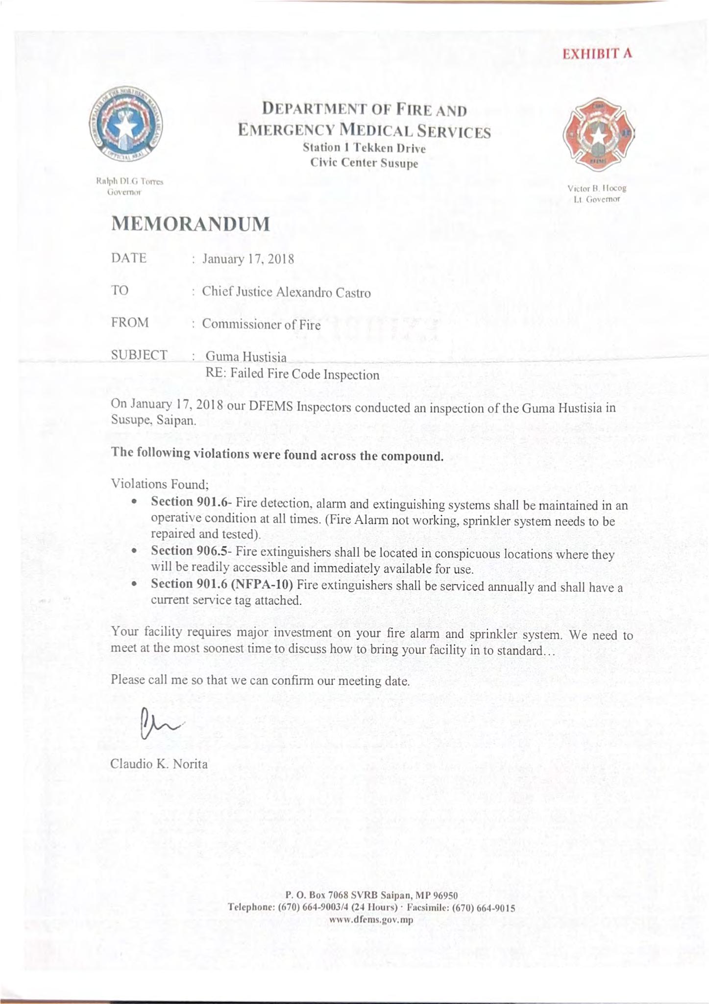
246

247

248
249


 Alarm and Sprinkler
SoniaA.Camacho DirectorofCourts
HyunJaeLee GemeralCounsel
JohnT.Villagomez BudgetandFinanceDirector
MarthaM.Standish ARPAAdministrator
MatthewJ.Brown DeputyGeneralCounsel
MaryBernadetteC.Glass Paralegal
KeithH.Ketola LawClerkto JusticeJohnA.Manglona


 Photo 1.0 Trane Chiller #3 control panel display of leaving and incoming chilled water temperature.
Photo 1.1 Corrosion are present on exposed chilled water piping.


 Photo 1.3 CHW #2 100-ton Trane Chiller
in 1998)
Photo 1.4 CHW #3 100-ton Trane Chiller
(installed in 1998)

 Photo 1.6 Chilled water pump # 1 (installed in 2012)


 Photo 1.8 Typical TRANE Air Handling Unit (AHU)
Photo 1.9 Honeywell 120 pints Dehumidifier typical to three. (recently installed)

 Photo 2.1 Typical Roof ventilators serving restrooms (installed 1998)

 Photo 2.3 Typical AHU Controller

 Photo 2.5 Typical AHU Timer


 Photo 2.6 Onset HOBO Data Loggers. Measures and transmits temperature and relative humidity data wirelessly to mobile devices via Bluetooth Low Energy (BLE) technology.
Photo 2.7 TSI's IAQ-Calc™ Indoor Air Quality Meter 7545 Measurements are CO, CO2, temperature, humidity; and calculations are dew point, wet bulb temperature, and % outside air.


 Photo 2.9 Inside view fresh air damper in one of the AHU serving the superior court. Damper is closed and corroded.
Photo 3.0 Fresh air intake louver (No protection against rain water carry-over)


 Photo 3.2 Inside view of AHU #11 equipment base casing is corroded and insulation is damped with moisture.
Photo 3.3 AHU #7 Equipment Base casing is completely missing.


 Photo 3.5 Inside View of Air Duct System (accumulation of dust is present)
Photo 3.6 The old motorized motor and control wiring is left disconnected.


 Photo 3.8 AHU #3 Dirty Cooling Coil
Photo 3.9 AHU #14 Insulation is compromised due to installation of Dehumidifier.

 Photo 4.1 Water ponding in some area of the roof is seen.

 Photo 4.3 Window double panes is leaking, and condensation is present between the glass panes.


 Photo 4.5 Wall exhaust fan was installed, and window is left open.
Photo 4.6 Water damage around window


 Photo 4.8 Water damage on ceiling tiles
Photo 4.9 Water damage on ceiling tiles


 Photo 5.1 Dust particle present in ceiling diffuser (indicates ineffective AHU filter system)
Photo 5.2 Sagging ceiling tiles (indicates ceiling tiles was exposed to high humid environment.)

 Photo 5.4 Disconnected Ductwork inside ceiling

 Photo 5.7 Discarded carpets are kept inside the building.

 Photo 5.9 Spot reading on 2nd floor Superior court admin Corridor


