Chapter 4: Forces in Structures and Machines
Discussion:
If an axis system in line with the directions of the forces is used, the magnitude is simply:
R = (12kN)2 + (2kN)2 =12.16 kN . The direction of the resultant force is offset less than 10° from the 12-kN force becauseof the size of the 12-kN force relative to the 2-kN force.
65 © 2017 Cengage Learning® May not be scanned, copied or duplicated, or posted to a publicly accessible website, in whole or in part.
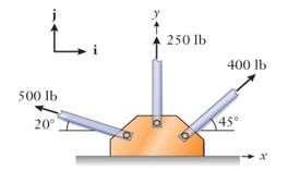
P4.6: Three tension rods are bolted to a gusset plate. Determine the magnitude and direction of their resultant Use the (a) vector algebra and (b) vector polygon methods. Compare the answers from the two methods to verify the accuracyof your work.
Approach:
Using the unit vectors, combine the horizontal and vertical components by the vector algebra method using Equations (4.4)–(4.6) Apply Equation (4.7):
to find the resultant's magnitude and angle of action. Make a scale drawing of the vector polygon and measure the resultant's length and angle graphically.
Solution:
(a) Vector algebra approach
The inverse tangent calculation would place the vector in the fourth quadrant, although it actually lies in the second quadrant since Rx < 0 and Ry > 0. Making this adjustment for the principal value of the angle, the proper angle, counterclockwise from i, is 180° – 75.1° = 104.9°. 728
104.9° counterclockwisefrom i
(b) Vector polygon method
Chapter
66 © 2017 Cengage Learning® May not be scanned, copied or duplicated, or posted to a publicly accessible website, in whole or in part.
4: Forces in Structures and Machines Chapter 4: Forces in Structures and Machines
2 2 1 R y R = R x + R y and = tan R x
F1 = (500 lb) ( cos 20° i + sin 20° j)= –469.8 i +171.0 j lb F2 = (250 lb)j F3 = (400 lb) (cos 45° i + sin 45° j)= 282.8 i + 282.8 j lb R = ( 469.8 + 0 + 282.8) i + (171.0 + 250 + 282.8) j lb = –187 i +703.8 j lb R = ( 187lb)2 + (703.8lb)2 = 728 2lb = tan 1 703.8lb = 75 12o 187 lb
lb,
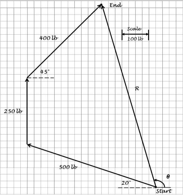
Add the three vectors graphically on a scale drawing using the head–to–tail rule. The magnitude and angle are measured from the drawing as 730 lb and 105°, which confirms the calculation from part (a).
67 © 2017 Cengage Learning® May not be scanned, copied or duplicated, or posted to a publicly accessible website, in whole or in part.
Chapter 4: Forces in Structures and Machines Chapter 4: Forces in Structures and Machines
Discussion:
The answers from the two methods match, as expected. The resultant force is less than the sum of the forces because the forces are oriented in different directions. Also note that some of the horizontal components of the 400-lb and 500-lb forces offset each other. Increasing the 250-lb force would increase the j component of the resultant force, but would not impact the i component.
Chapter 4:
in Structures
Machines Chapter 4:
in Structures
Machines 68 © 2017 Cengage Learning® May not be scanned, copied or duplicated, or posted to a publicly accessible website, in whole or in part.
Forces
and
Forces
and
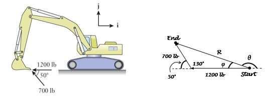
P4.7: The bucket of the excavator at a construction site is subjected to 1200 lb and 700 lb digging forces at its tip. Determine the magnitude and direction of their resultant Use the (a) vector algebra and (b) vector polygon methods. Compare the answers with the two methods to verify the accuracyof your work.
Approach:
Using the unit vectors, combine the horizontal and vertical components by the vector algebra method using Equations (4.4)–(4.6).Apply Equation (4.7)
to find the resultant's magnitude and angle of action. Draw a vector polygon using the head
to
tail rule and apply laws of geometryto determine the magnitude and angle.
Solution:
(a) Vector algebra method
F1 = (1200 lb) (−i) = –1200 i lb
F2 = (700 lb) ( cos 50° i + sin 50° j) = –450 i + 536.2 j lb
R = ( 1200 – 450) i + 536.2 j lb
= –1650 i +536.2 j lb
R = ( 1650lb)2 + (536.2lb)2 = 1735lb = tan
The inverse tangent calculation would place the vector in the fourth quadrant, although it actually lies in the second quadrant since Rx < 0 and Ry > 0. Making this adjustment for the principal value of the angle, the proper angle, counterclockwise from i, is 180° – 18° = 162°.
1735 lb, 162° counterclockwisefrom i
(b) Vector polygon method
69 © 2017 Cengage Learning® May not be scanned, copied or duplicated, or posted to a publicly accessible website, in whole or in part.
Chapter 4: Forces in Structures and Machines Chapter 4: Forces in Structures and Machines
2 2 1 R y R = R x + R y and = tan R x
–
–
1
536.2lb = 18o
1650lb
Chapter 4: Forces in Structures and Machines
Chapter 4: Forces in Structures and Machines
Law of cosines (Equation B.17) for the magnitude:
R2 = (1200 lb)2 + (700 lb)2 – 2(1200 lb) (700 lb) cos 130°
= 3.01×10⁶ lb2
R = 1735 lb
70
May not be scanned, copied or duplicated, or posted to a publicly accessible website, in whole or in part.
© 2017 Cengage Learning®
Law of sines (Equation B.16) for the angle:
1735lb
sin130o = 700lb sin
sin φ = 0.3091
φ = 18°
θ = 180° –18° =162°
1735 lb, 162° counterclockwisefrom i
Discussion:
The answers from the two methods match, as expected. The resultant force is less than the sum of the forces because the forces are oriented in different directions.
71 © 2017 Cengage Learning® May not be scanned, copied or duplicated, or posted to a publicly accessible website, in whole or in part.
Chapter 4: Forces in Structures and Machines Chapter 4: Forces in Structures and Machines
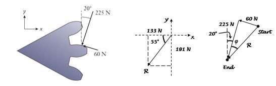
P4.8: Forces of 225 N and 60 N act on the tooth of a spur gear. The forces are perpendicular to one another, but they are inclined by 20° relative to the x–y coordinates. Determine the magnitude and direction of their resultant. Use the (a) vector algebra and (b) vector polygon methods. Compare the answers from the two methods to verify the accuracyof your work.
Approach:
Using the unit vectors, combine the horizontal and vertical components by the vector algebra method using Equations (4.4)–(4.6).Apply Equation (4.7):
to find the resultant's magnitude and angle of action. Draw a vector polygon using the head
to
tail rule and apply laws of geometryto determine the magnitude and angle.
Solution:
(a) Vector algebra method
The inverse tangent calculation would place the vector in the first quadrant, although it actually lies in the third quadrant since Rx < 0 and Ry < 0. Making this adjustment for the principal value of the angle, the proper angle, counterclockwise from i, is 180° + 55.1° = 235.1°.
232.8 N, 235° counterclockwisefrom i
(b) Vector polygon method
Chapter
Machines Chapter
Machines 72 © 2017 Cengage Learning® May not be scanned, copied or duplicated, or posted to a publicly accessible website, in whole or in part. x y
4: Forces in Structures and
4: Forces in Structures and
R = R2 + R2 and = tan 1 R y R x
–
–
F1 = (225 N) ( sin 20° i – cos 20° j) = –76.95 i – 211.4 j N F2 = (60 N) ( cos 20° i + sin 20° j) = –56.38 i + 20.52 j N R = (−76.95 – 56.38) i + (−211.4 + 20.52) j N = –133.3 i–190.9 j N R = ( 133.3N)2 + ( 190.9 N)2 = 232.8 N = tan 1 190.9N = 55.1o 133.3 N
Thetwo forces act at a right anglerelativeto oneanother,so the vectorpolygonis simplya right triangle:
Chapter 4: Forces in Structures and Machines
73 © 2017 Cengage Learning® May not be scanned, copied or duplicated, or posted to a publicly accessible website, in whole or in part.
Chapter 4: Forces in Structures and Machines
R = (225 N)2 + (60 N)2 = 232 8 N
= tan 1 60N = 14.9o
225N
The resultant R is directed 20° + 14.9° = 34.9° from vertical, and 180° + (90° – 34.9°) = 235.1° from the x–axis.
232.8 N, 235° counterclockwisefrom i
Discussion:
The answers from the two methods match, as expected. This problem illustrates that the law of cosines simplifies to the Pythagorean theorem when the forces are perpendicular to each other
74
Learning
May not be scanned, copied or duplicated, or posted
a publicly accessible website, in
or in part.
Chapter 4: Forces in Structures and Machines Chapter 4: Forces in Structures and Machines
© 2017 Cengage
®
to
whole
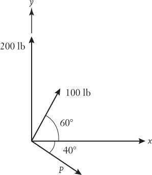
P4.9: The three forces (magnitudes 100 lb, 200 lb, and P) combine to produce a resultant R The three forces act in known directions, but the numerical value of P is unknown.
(a) What should the magnitude of P be so that the resultant is a small as possible? (b) For that value, what angle does the resultant make relative to the positive x-axis?
Approach:
Draw a vector polygon and add the three forces using the head–to–tail rule. The magnitude of P can then be found geometrically by adding two parts of the length of the vector The resultant force vector will have the smallest magnitude when it is perpendicularto P.
Chapter
70 © 2017 Cengage Learning® May not be scanned, copied or duplicated, or posted to a publicly accessible website, in whole or in part.
4: Forces in Structures and Machines Chapter 4: Forces in Structures and Machines

Chapter 4: Forces in Structures and Machines Chapter 4: Forces in Structures and Machines 71 © 2017 Cengage Learning® May not be scanned, copied or duplicated, or posted to a publicly accessible website, in whole or in part.
Solution:
(a) From the diagram, | P | = (200 lb)sin 40° + (100 lb)sin 10° = 145.9 lb 145.9 lb
(b) Since P acts at 40° relative to horizontal, and the resultant is perpendicular to it, the resultant acts at 40° relative to vertical, or 50° relative to the x–axis. 50° relative to the positive x–axis
Discussion:
This result can also be found by utilizing the fact that R and P are perpendicular and then using the vector algebra method to express R in terms of P and the two known forces. This will result in two equations with two unknowns which can be solved for R and P
72 © 2017 Cengage Learning® May not be scanned, copied or duplicated, or posted to a publicly accessible website, in whole or in part.
Chapter 4: Forces in Structures and Machines Chapter 4: Forces in Structures and Machines
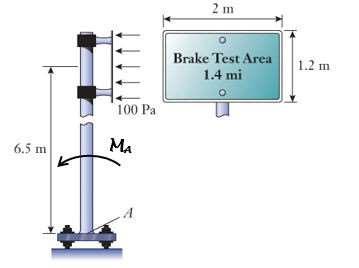
P4.11: Resulting from a light wind, the air pressureimbalanceof 100 Pa acts across the 1.2 m by 2 m surface of the highway sign. (a) Calculate the magnitude of the force acting on the sign. (b) Calculate the moment produced about point A on the base of the sign pole.
Approach:
The magnitude of the force acting on the sign is the product of the pressure imbalance and the sign's area. Find the moment about A using Equation (4.8) MA = Fd assuming the force acts at the center of the sign. Recall from Table 3.2 that 1 Pa = 1 N/m2 .
Solution:
(a) Force magnitude
F = (100 Pa) (2 m) (1.2 m) = 240 N 240 N
(b) Moment about point A
MA = (240 N) (6.5 m) = 1560 Nm
1560 N m (counterclockwise)
Discussion:
This is a nominal force and moment, as any wind will most likely be variable in nature, creating fluctuating forces and moments. The longer the sign pole, the larger the moment will be.
Chapter
73 © 2017 Cengage Learning® May not be scanned, copied or duplicated, or posted to a publicly accessible website, in whole or in part.
4: Forces in Structures and Machines Chapter 4: Forces in Structures and Machines
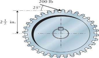
P4.12: The spur gear has a pitch of 2.5 in. During a geartrain's operation, a 200 lb meshing force acts at 25° relative to horizontal. Determine the moment of that force about the center of the shaft. Use the (a) perpendicular lever arm and (b) moment components methods.Comparetheanswersofthetwo methodstoverifytheaccuracyof yourwork.
84.5 lb
Approach:
A componentof the force is directed radiallytoward the shaft's center, and it contributesno moment about that point Apply Equation (4.8) M = Fd and find the perpendicular lever arm distance d from the gear's geometry. Then use Equation (4.9) M = ±Fx∆y ± Fy∆x and the positive sign convention when applying the moment components method.
Solution:
(a) Perpendicularlever arm
d = (2.5 in.)cos 25° = 2.266 in.
M0 = (200 lb) (2.266 in.) = 453.2 in lb
453 in lb (clockwise)
(b) Moment components.Rectangular components and lever arms of the 200 lb force:
|Fx| = (200 lb)cos 25° =181.3 lb
|Fy| = (200 lb) sin 25° = 84.53 lb
∆x = 0
∆y = 2.5 in.
M0 = –(181.3 lb)( 2.5 in.) + (84.53 lb) (0) = –453.2 in lb Since the result is negative, the net moment is directed clockwise.
453.2 in lb (clockwise)
Discussion:
The methods give the same result, as expected. Both methods require an engineer to keep track of the moment directions carefully. If the gear was larger, the diameter would be larger, creating a larger moment around the center of the gear.
Chapter
Machines
74 © 2017 Cengage Learning® May not be scanned, copied or duplicated, or posted to a publicly accessible website, in whole or in part.
4: Forces in Structures and
Chapter 4: Forces in Structures and Machines
181 lb 25° y + x 2.5 in d 25° Line of action Point O
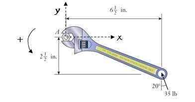
P4.13: Determine the moment of the 35 lb force about the center A of the hex nut.
Approach:
Find the rectangular components of the force, and their lever arms. Then apply Equation (4.9):
M = ±Fx∆y ± Fy∆x
Use the x-y coordinates and positive sign convention shown on the drawing.
Solution:
Find the rectangular components of the 35 lb force, and their lever arms:
|Fx| = (35 lb) sin 20° = 11.97 lb
|Fy| = (35 lb) cos 20° = 32.89 lb
∆x = 6.5 in.
∆y = 2.5 in.
MA = –(11.97 lb) (2.5 in.) + (32.89 lb) (6.5 in.) = 183.9 in lb
Since the result is positive, the net moment is directed counterclockwise. 184 in lb (counterclockwise)
Discussion:
The clockwise moment created by the horizontal component of the force is offset by some of the counterclockwisemoment created by the vertical component of the force. Of course, as the nut gets tighter or looser, the magnitude of the moment will change If the wrench was longer, a larger moment would be created about the nut.
Chapter
75 © 2017 Cengage Learning® May not be scanned, copied or duplicated, or posted to a publicly accessible website, in whole or in part.
4: Forces in Structures and Machines Chapter 4: Forces in Structures and Machines
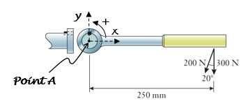
P4.14: Two construction workers pull on the control lever of a frozen valve. The lever connects to the valve's stem through the key that fits into partial square grooves on the shaft and handle. Determine the net moment about the center of the shaft.
Approach:
Find the rectangular components of the 200 N force, and combine with the 300 N force. Find the lever arms for the net x and y components,and apply Equation (4.9):
M = ±Fx∆y ± Fy∆x
Use the x-y coordinates and positive sign convention shown on the drawing.
Solution:
Resultant horizontal and vertical force components and their lever arms:
Since the result is negative, the moment is directed clockwise according to the sign convention.
122 N m (clockwise)
Discussion:
The horizontal component of the 200 N force does not create a moment about the center of the shaft. If the lever was longer, a larger moment would be created about the center of the shaft.
76 © 2017 Cengage Learning® May not be scanned, copied or duplicated, or posted to a publicly accessible website, in whole or in part.
Chapter 4: Forces in Structures and Machines Chapter 4: Forces in Structures and Machines
M
|Fx| = (200 N) sin 20° = 68.40 N |Fy| = (200 N) cos 20° + 300 N = 487.9 N ∆x = 0.25 m ∆y = 0 Net moment:
A = (68.40 N) (0) – (487.9 N) (0.25 m) = –122 N m
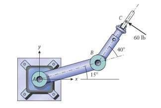
P4.15: Gripper C of the industrial robot is accidentally subjected to the 60 lb side load, directedperpendicularto BC The lengths of the robot's links are AB = 22 in. and BC = 18 in. By using the moment components method, determine the moment of this force about the center of joint A.
Approach:
Find the rectangular components of the force, and their lever arms. Then apply Equation (4.9):
M = ±Fx∆y ± Fy∆x
Use the x–y coordinates and positive sign convention shown on the drawing.
Solution:
Resultant horizontal and vertical force components and their lever arms:
|Fx| = (60 lb) cos 35° = 49.15 lb
|Fy| = (60 lb) sin 35° = 34.41 lb
∆x = (22 in ) cos 15° + (18 in.) cos 55° =31.57 in.
∆y = (22 in.) sin 15° + (18 in.) sin 55° = 20.44 in.
MA = +(49.15 lb) (20.44 in.) + (34.41 lb) (31.57 in.) = 2091 in lb
Since the result is positive, the moment is directed counterclockwise Convert to ft lb so that the numerical value for MA is smaller.
(2091in lb)0.0833 ft = 174.3ft lb
174 ft lb (counterclockwise)
Discussion:
This analysis assumes an instantaneous moment about joint A. The force also creates a moment about joint B and dependingupon whetheror not the arm can rotate at joint A or B, and the friction in the joint bearings, the resultant arm motion will vary.
Chapter
77 © 2017 Cengage Learning® May not be scanned, copied or duplicated, or posted to a publicly accessible website, in whole or in part.
4: Forces in Structures and Machines Chapter 4: Forces in Structures and Machines
in
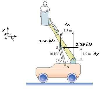
P4.16: The mobile boom lift is used in construction and maintenance applications. The hydraulic cylinder AB exerts a 10 kN force on joint B which is directed along the cylinder. By using the moment components method, calculate the moment of this force about the lower support point C of the boom.
Approach:
Find the rectangular components of the force, and their lever arms. Then apply Equation (4.9):
M = ±Fx∆y ± Fy∆x Use the x–y coordinates and positive sign convention shown on the drawing.
Solution:
Horizontal and vertical force components and their lever arms:
|Fx| = (10 kN) cos 75° = 2.588 kN
|Fy| = (10 kN) sin 75° = 9.659 kN
∆x = 1.3 m
∆y = 1.5 m
MC = +(2.588 kN) (1.5 m) – (9.659 kN) (1.3 m) = –8.675 kN m
Since the result is negative, the net moment is directed clockwise
8.675 kN m (clockwise)
Discussion:
This moment is appropriate because the resultant motion from this force should be a clockwise rotation of the boom, lifting the worker higher As the boom continues to rotate, this moment will change in magnitude as the moment arms will change.
78 © 2017 Cengage Learning® May not be scanned, copied or duplicated, or posted to a publicly accessible website, in whole or in part.
Chapter 4: Forces in Structures and Machines Chapter 4: Forces in Structures and Machines
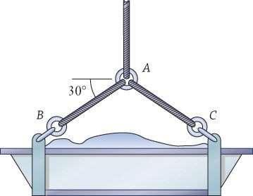
P4.17: The trough of concrete weighs 800 lb. (a) Draw a free body diagram of the cable's ring A (b) Treating the ring as a particle, determine the tension in cables AB and AC
Approach:
The three tension forces act along the cables. Sum the forces on a vector polygon using the head–to–tail rule. Assuming the suspension system is in static equilibrium, the polygon's start and end points are the same since there is zero resultant force acting on the ring. The weights of the cables and ring are not considered.
Solution:
(a) See diagram
(b) Using symmetryand summing horizontal force components, AB = AC. The vector polygon is a graphical way of writing ΣF = 0:
AB sin 30° = 400 lb
AB = 800 lb
AB = AC = 800 lb
Discussion:
This answer is reasonable because only ½ of the tension in these cables is being used to support the vertical weight of the trough. Therefore each cable supports ½ of the weight of the trough, or 400 lb. The horizontal components of the tension are present because of the placement of the cables on the trough. These horizontal componentsare equal inmagnitude but opposite in direction, offsetting each other.
79 © 2017 Cengage Learning® May not be scanned, copied or duplicated, or posted to a publicly accessible website, in whole or in part.
Chapter 4: Forces in Structures and Machines Chapter 4: Forces in Structures and Machines
y 30° x AB 800 lb 30° AC AB 30° 30° AC 800 lb Start/End
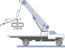
P4.18: Cable AB of the boom truck is hoisting the 2500 lb section of precast concrete. A second cable is under tension P, and workers use it to pull and adjust the position of the concretesection as it is beingraised. (a) Draw a freebodydiagram of hook A, treatingit as a particle. (b) Determine P and the tension in cable AB.
Approach:
The two tension forces act along the cables. Sum the forces on a vector polygon using the head–to–tail rule. Assuming the hook is in static equilibrium, the polygon's start and end points are the samesince thereis zeroresultant force actingon the hook. Theweights of the cable and hook are not considered.
Solution:
(a) See diagram
(b) Find AB and P by applying the law of sines (Equation B.17 in Appendix B) to the vector polygon. The polygon is a graphical way of writing ΣF = 0.
AB = 2500lb
sin115o sin60o
AB = 2616 lb
P = 2500lb
sin5o sin60o
P = 251.6 lb
AB = 2616 lb and P = 252 lb
Discussion:
80 © 2017 Cengage Learning® May not be scanned, copied or duplicated, or posted to a publicly accessible website, in whole or in part.
Chapter 4: Forces in Structures and Machines Chapter 4: Forces in Structures and Machines
5° AB 25° Start/End P 2500 lb 180° - 5°115° = 60° AB 30° 5° 25° 2500 lb
It makes sense that the tension in AB is much larger than P because AB is supportingall the weight of the concrete section. The angle between AB and P in the vector polygon can also be foundby(90o - 5o - 25o)= 60o . Whenworkers arepositioningthe concrete,the hookmay not be in static equilibrium, but may be accelerating or decelerating In this case, the behavior is governed by Newton’s Second Law of Motion.
81 © 2017 Cengage Learning® May not be scanned, copied or duplicated, or posted to a publicly accessible website, in whole or in part.
Chapter 4: Forces in Structures and Machines Chapter 4: Forces in Structures and Machines
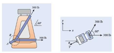
P4.19: Solve the problem of Example 4.5 by using the force components method. Replace the polar representation of the anchor strap's tension by the horizontal and vertical components Tx and Ty, and solve for them. Use your solution for Tx and Ty to determine the magnitude T and direction θ of the anchor strap's tension.
Approach:
Use the FBD and coordinate system shown in the figure. The tension force is T = Tx i + Ty j. Assume the strap system is in equilibrium and then write the equilibrium equations in x and y using the vector algebra approach.
Solution: Write the given forces as vectors:
F1=300 i lb
F = (300 lb)(cos60o i + sin60o j) = 150 i +259.8 j lb
Equilibrium ΣF = 0: (Tx i + Ty j)+ (300 i lb)+ (150 i + 259.8 j lb) = 0
Components:
Tx+ 300 lb + 150 lb = 0
Tx = –450 lb
Ty + 259.8 lb = 0
Ty = –259.8 lb
Tx = –450 lb Ty = –260 lb
Resultant:
T = ( 450lb)2 + ( 260lb)2 = 519 6lb
519.6 lb, 30°
80 © 2017 Cengage Learning® May not be scanned, copied or duplicated, or posted to a publicly accessible website, in whole or in part. 2
Chapter 4: Forces in Structures and Machines Chapter 4: Forces in Structures and Machines
1
= tan
260lb = 30o
450lb
Discussion:
It makes sense that the horizontal component of the tension is larger than the vertical component since the tension in the lap strap is completely horizontal. If the tension in the lap strap were to increase,then the angle of the resultant force would decrease(it would get closer to being horizontal).
Chapter
81 © 2017 Cengage Learning® May not be scanned, copied or duplicated, or posted to a publicly accessible website, in whole or in part.
4: Forces in Structures and Machines Chapter 4: Forces in Structures and Machines
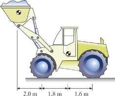
P4.20: The front loader of mass 4.5 Mg is shown in side view as it lifts a 0.75 Mg load of gravel (a) Draw a free body diagram of the front loader (b) Determine the contact forces between the wheels and the ground. (c) How heavy a load can be carried before the loader will start to tip about its front wheels?
Approach:
Let F and R be the contact forces on one front and one rear tire. There are two unknowns. Assuming the system is in static equilibrium, write a force balance in the vertical direction and a moment balance about the front wheels.
Solution:
(a) See sketch above for the FBD
(b) The two unknowns are F and R. The weights are:
Machines 82 © 2017 Cengage Learning® May not be scanned, copied or duplicated, or posted to a publicly accessible website, in whole or in part. Mg 1
Chapter 4: Forces in Structures and Machines Chapter 4: Forces in Structures and
w1 w2 y + x 2F 2R
w = (0 75 Mg)1000 kg 9.81 m = 7357 N = 7 357kN Mg s 2 w = (4.5Mg)1000 kg 9.81 m = 44,145N = 44 15kN 2 s 2 Apply ΣMA = 0 to eliminate F and find R: + (7.357 kN) (2.0 m) – (44.15 kN) (1.8 m) + (2R) (3.4 m) = 0 R = 9.523 kN Substitute for R and apply ΣFy =0 to find F: – 7.357 kN + 2F– 44.15 kN + 2(9.523 kN) = 0 F = 16.23 kN
Front wheel: 16.2 kN
Rear wheel: 9.52 kN
Chapter
83 © 2017 Cengage Learning® May not be scanned, copied or duplicated, or posted to a publicly accessible website, in whole or in part.
4: Forces in Structures and Machines Chapter 4: Forces in Structures and Machines
(c) The two unknowns are w1 and F. At the condition of tipping, R = 0. Apply Σ MA = 0 to eliminate F and find w1 + w1(2.0 m) – (44.15 kN)(1.8 m)=0
w1 = 39.74 kN 39.7 kN
Discussion:
The front contact force is larger than the rear because of the gravel load positioned at the front of the loader. If the load is lowered, creating a longer moment arm, then the required load to cause the loader to start tipping would decrease
84 © 2017 Cengage Learning® May not be scanned, copied or duplicated, or posted to a publicly accessible website, in whole or in part.
Chapter 4: Forces in Structures and Machines Chapter 4: Forces in Structures and Machines
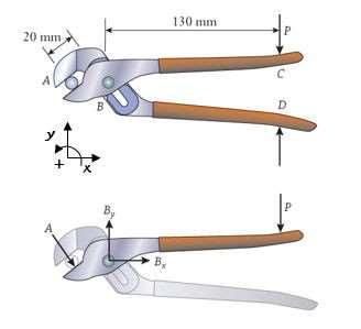
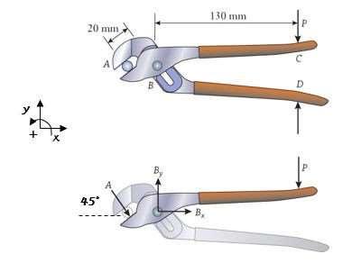
P4.21: Adjustable pliers hold a round metal bar as a machinist grips the handles with P = 50 N. Using the free body diagram shown for the combined lower jaw and upper handle, calculate the force A that is applied to the bar.
Approach:
Assumingthe system is in staticequilibriumand with a momentbalanceabout point B, the unknowns Bx and By are eliminated.
Solution: Apply the moment balance Σ MB =0 on the free body diagram to eliminate Bx and By
(50 N) (0.13 m) + A(0.02 m) = 0
A = 325 N 325 N
Discussion:
If the lower jaw handle was isolated instead, the same force would be applied to the other side of the bar. If the pliers handle was longer, the force applied would be greater.
Chapter
85 © 2017 Cengage Learning® May not be scanned, copied or duplicated, or posted to a publicly accessible website, in whole or in part.
4: Forces in Structures and Machines Chapter 4: Forces in Structures and Machines
–
P4.22:Refer to P4.21. (a) Measurethe angle of force A directlyfrom the diagram and use it to find the magnitude of the force at hinge B (b) A design condition is that the force at B should be less than 5 kN. What is the maximum force that a machinist can apply to the handle before that condition is reached?
Approach:
From P4.21, A = 325 N. Measure the angle of A as 45°. Sum the horizontal and vertical force components on the FBD to find Bx and By. Find the force's magnitude using: 2 2 B = B x + B y
Solution:
(a) Force balances
ΣFx = 0
Bx + (325 N) cos 45° = 0
Bx = –299.8 N
ΣFy = 0:
By – (325 N) sin 45° – 50 N = 0
By = 279.8 N
Resultant:
(b) Forces A, Bx and By each increase in direct proportion to P, so the magnitude B is also proportional to P. P max = 50N 5000N 362.1N
86 © 2017 Cengage Learning® May not be scanned, copied or duplicated, or posted to a publicly accessible website, in whole or in part.
Chapter 4: Forces in Structures and Machines Chapter 4: Forces in Structures and Machines
2
278.8
2
362
B = ( 229 8 N)
+ (
N)
= 362.1N
N
Chapter 4: Forces in Structures and Machines Chapter 4: Forces in Structures and Machines 87 © 2017 Cengage Learning® May not be scanned, copied or duplicated, or posted to a publicly accessible website, in whole or in part. Pmax = 690 N 690 N
Discussion:
Alternatively, one could use the moment equation from P4.21 to solve for A as a function of P. Substitutethis equation for A into the force balanceequations in part (a). Then,choose a value for P and solve for B and check the 5 kN constraint. Iterate until B just equals 5 kN. If the pliers handlewas longer,the maximumforcewouldbe smaller,sincethemoment arm would be longer.
Chapter
88 © 2017 Cengage Learning® May not be scanned, copied or duplicated, or posted to a publicly accessible website, in whole or in part.
4: Forces in Structures and Machines Chapter 4: Forces in Structures and Machines
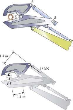
P4.23: A pair of large hydraulically operated shears is attached to the end of the boom on an excavator. The shear is used for cutting steel pipe and I-beams during demolition work. Hydraulic cylinder AB exerts an 18 kN force on the upper jaw. (a) Complete the free body diagram for the upper jaw, which has been only partially drawn. (b) Determine the cutting force F being applied to the pipe.
Approach:
Assuming the system is in static equilibrium, use the FBD and balance moments about point C to eliminate unknowns Cx,and Cy, and solve for F.
Solution:
(a) See sketch above for the FBD
(b) Apply the moment balance Σ MC = 0 to eliminate Cx and Cy and find the cutting force:
–F(1.1 m) + (18 kN)(1.4 m) = 0
F = 22.91 kN
22.9 kN
Discussion:
89 © 2017 Cengage Learning® May not be scanned, copied or duplicated, or posted to a publicly accessible website, in whole or in part.
Chapter 4: Forces in Structures and Machines Chapter 4: Forces in Structures and Machines
y + x Cy Cx
The cutting force is larger than the applied hydraulic force which makes sense This is becausethe moment arm to the cutting force about C is smaller than the moment arm to the hydraulic force
90 © 2017 Cengage Learning® May not be scanned, copied or duplicated, or posted to a publicly accessible website, in whole or in part.
Chapter 4: Forces in Structures and Machines Chapter 4: Forces in Structures and Machines
P4.24: A cross section of the original design for the double-decker skyways in the Kansas City Hyatt Regency hotel is shown, along with the forces acting on the nuts and washers that support the upper and lower walkways. (a) Draw free body diagrams of the upper and lower walkways,including the weight w that acts on each. (b) Determine the forces P1 and P2 between the washers and the walkways, and the tensions T1 and T2 in the hanger rod.
Approach:Usethe given informationfor the tensions T1 and T2, and the forces betweenthe washers and walkways. The forces P1 and P2 act upward on the walkways.
Solution:
(a) See FBD drawings above
(b) For the lower walkway, P2 = w/2. From the given FBD for the lower nut and hanger rod, T2 = P2 = w/2.
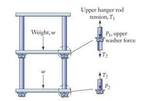
From the FBD of the upper walkway, P1 = w/2. From the given FBD for the upper nut and hanger rod,
T1–P1

T2=0
T1=P1+T2
Chapter
91 © 2017 Cengage Learning® May not be scanned, copied or duplicated, or posted to a publicly accessible website, in whole or in part.
4: Forces in Structures and Machines Chapter 4: Forces in Structures and Machines
–
=
=
w + w 2 2
w
Each nut carries a force equal to half of a walkway's weight
Chapter 4:
in
Machines
in
Machines 92 © 2017 Cengage Learning® May not be scanned, copied or duplicated, or posted to a publicly accessible website, in whole or in part.
Forces
Structures and
Chapter 4: Forces
Structures and
The lower portion of the hanger rod has tension w/2. The upper portion of the hanger rod has tension w
Discussion:
Theseforces makesense becauseof the symmetry of the walkway with equivalent supports on each end. Under normal use, these forces and tensions would be higher due to daily foot traffic on the walkway.
Chapter
Machines
4:
in
Machines 93 © 2017 Cengage Learning® May not be scanned, copied or duplicated, or posted to a publicly accessible website, in whole or in part. P = P = w 2 T1 = w T = w 2 2
4: Forces in Structures and
Chapter
Forces
Structures and
1 2
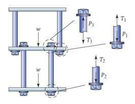
P4.25: A cross-sectional view is shown of the skyways in the Kansas City Hyatt Regency hotel in their as-constructedform, along with the forces acting on the nuts and washers that contact the two walkways. (a) Draw free body diagrams of the upper and lower walkways, including the weight w that acts on each. (b) Determine the forces P1, P2, and P3 between the washers and the walkways, and the tensions T1, T2, and T3 in the hanger rods. (c) The skyways'collapse was associated with an excessive force P1. How does the value you calculated here compare with the value of P1 obtained in P4.24?
Approach:
Use the FBDs of the nuts that support the two walkways. Draw FBDs of the walkways, showing the weight and forces P1, P2 and P3
Solution:
(a) See FBD drawings above.
(b) For the lower walkway, P2 = w/2. From the given FBD for the lower nut and hanger rod:
T2 = P2 = w/2.
From the FBD for the inboard nut on the upper walkway, P3 = T3 For the lower rod, T3 = T2, so: P3 = T2 = w/2.
From the FBD for the upper walkway, –w – 2P3 + 2P1 = 0

90 © 2017 Cengage Learning® May not be scanned, copied or duplicated, or posted to a publicly accessible website, in whole or in part. e s
Chapter 4: Forces in Structures and Machines Chapter 4: Forces in Structures and Machines
The nut on the lower walkway carries a force equal to half of a walkway's weight. The outboard nut on the upper walkway carries a force twice as large.
(c) The force between the walkwayand the outboardnut attached to the upper hangerrod is twice as large in the as-constructed structure when compared to the as-designedskyway
Discussion:
This illustrates how the failure could have occurred if proper force analysis was not applied to the new walkwaydesign. Supportinga force twice as large as expectedalong with heavy foot traffic, it is clear how the structure could have failed.
Chapter 4: Forces in Structures
Machines Chapter 4:
in Structures and Machines 91 © 2017 Cengage Learning® May not be scanned, copied or duplicated, or posted to a publicly accessible website, in whole or in part. e s P1 = w P = P T1 = w T = T = w 2 P = w + P = w + w = w 1 2 3 2 2
and
Forces
= w 2 3 2 2 3
P4.26: A handrail, which weighs 120 N and is 1.8 m long, was mounted to a wall adjacent to a small set of steps. The support at A has broken, and the rail has fallen about the loose bolt at B so that one end now rests on the smooth lower step. (a) Draw a free body diagram of the handrail. (b) Determine the magnitude of the force at B.
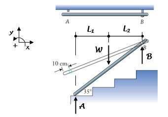
Approach:
The contact force between the rail and step is unknown in magnitude, but it does act vertical Assuming the rail is in static equilibrium and by balancing moments about that contact point, that unknown is eliminated and B can be found directly.
Solution:
(a) See sketch above for the FBD
(b) Force at connection B
Lever arm lengths:
L1 = (0.9 m) cos 35° = 0.7372 m
L2 = (0.9 m–0.1 m) cos 35° = 0.6553 m
Apply the moment balance Σ MA = 0 to eliminate A: – (120 N)(0.7372 m)+ B(0.7372 m + 0.6553 m) = 0
B = 63.53 N
63.5 N
Discussion:
The force at A can be found by either balancingmoments around B or summingthe vertical forces. The forceat A is less than the force at B becausethe moment arm measuredfrom the center of the handrail to point A is longer than to point B.
92 © 2017 Cengage Learning® May not be scanned, copied or duplicated, or posted to a publicly accessible website, in whole or in part. e s
Chapter 4: Forces in Structures and Machines Chapter 4: Forces in Structures and Machines


