Modern Electrical Communications Analog Digital and Optical Systems 1st edition by Henry Stark, Franz Tuteur, John Anderson ISBN 0135931126 978-0135931127
Enabling Blockchain Technology for Secure Networking and Communications 1st Edition by Adel Ben Mnaouer, Lamia Chaari Fourati 1799858405 978-1799858409
(Ebook PDF) Design in Educational Technology Design Thinking Design 1st edition by Brad Hokanson, Andrew Gibbons 3319009265Â 978-3319009261 full chapters
Modern C Design Generic Programming and Design Patterns Applied 1st Edition by Andrei Alexandrescu, Scott Meyers, John Vlissides ISBN 9780133387612 0133387615
(Ebook PDF) HANDBOOK OF RESEARCH ON EDUCATIONAL COMMUNICATIONS TECHNOLOGY A Project of the Association for Educational Communications and Technology 2nd edition by Michael Spector, David Merrill, Jeroen van Merriënboer, Marcy Driscoll 1135596905 9781135596903 full chapters
All rights reserved. Printed and bound in the United States of America. No part of this book may be reproduced or utilized in any form or by any means, electronic or mechanical, including photocopying, recording, or by any information storage and retrieval system, without permission in writing from the publisher. All terms mentioned in this book that are known to be trademarks or service marks have been appropriately capitalized. Artech House cannot attest to the accuracy of this information. Use of a term in this book should not be regarded as affecting the validity of any trademark or service mark.
10 9 8 7 6 5 4 3 2 1
7.2
13.5 Understanding the Third-Order Intercept Point Spurious-Free Dynamic Range (IP3SFDR)
13.6 Simulating and Measuring
CHAPTER 14 High-Performance
14.2
14.3
CHAPTER 15
15.5
15.6
15.7
15.13
15.14
16.6
16.8 Open Loop Systems: Mixing VFOs with Crystal Oscillators
16.9 Synthesizer Forms and Classifications: Brute Force, Direct and Indirect, and Nonbrute Force, Direct and Indirect
16.21 Designing a High-Performance MRU for an HPOI
16.26 Designing a DDS-Driven PLL Synthesizer for the Upconvert, Double Conversion HPOI
16.27 Performance of the DDS-Driven PLL
16.28 The Opto-Encoder and Its Application
16.29 Key Rules in Designing PLLs
16.30 Problems: Design a Synthesized Receiver System for the FM
16.31 Final Concluding Notes to Synthesizers
17.4
18.8
18.9
25.8
25.9
Foreword
Any author who attempts to comprehensively cover the many, many aspects of receiver design and their complex interrelationships is up to a gigantic job. To even know that certain aspects exist often takes decades of experience in not only the design and analysis of radio receivers, but also, most importantly, in the lab bench experience gained in building actual receiver hardware. Cornell Drentea is an excellent author for this task.
Readers who are new to the topic of radio communications receivers will find the early chapters of this book of most value. As the experience of the reader grows, the advanced material in subsequent chapters will make more sense. This book provides a comprehensive overview of how RF system requirements flow into designs as well as hands-on use of state-of-the-art system design tools. It is ultimately an advanced study of practical receiver systems and circuit design.
One aspect of this book that I particularly like is Mr. Drentea’s placing of much of this material in a historical context. It is important, if one is to make true progress in any field, to understand how that field of work has evolved into its current state. One of my favorite quotations is, “Those who cannot remember the past are condemned to repeat it” (Santayana). We are fortunate that Mr. Drentea has a tremendous amount of experience and remembers how he got it. For those of us who cannot remember the past because we are new to a topic we must study its past to build a useful foundation. This leads to an appropriate paraphrase of Santayana: Those who do not study history are doomed to repeat it. I commend Mr. Drentea for providing this reference.
Because the subject is so vast, Mr. Drentea chose to emphasize certain technical areas that cannot usually be found in one single publication and combine them with facts and experiences of his own in such a way as to provide a complete and accelerated learning reference. I find this to be a well thought out book with lots of material good for advanced engineering students as well as for practicing hardware and system design engineers. The format and approach are logical and easy to follow. This book is complete and in depth where it matters. It flows well and it has a lot of material that is not easily (or possibly) found anywhere else.
This work should be good for anyone considering an RF signal processor (radio) concept. A very useful reference, this book is particularly helpful to an RF systems engineer or operations planner in EW, reconnaissance, or a similar field dealing with a wide variety of signals, environments, and operating conditions. It gives powerful tools for the trade-off of requirements against potential solution approaches.
This book provides an excellent knowledge base of well-interlocked topics. It reflects the passion the author has put into what he does best. I appreciate the level of effort it took to put together a course of this magnitude. I was especially impressed with the presentation of this complex information content, and the great spirit that is put into it.
Earl McCune, Jr., Ph.D.
RF Communications Consulting
Santa Clara, California August 2010
Preface
This book is built on the success of my previous book, Radio Communications Receivers, first published in 1982 and republished in 1984.
While keeping the same basic format, the new book attacks the topics of all types of receivers, not just communications receivers. It focuses on the high probability of intercept receivers. The material has been greatly expanded with many new and complex topics to reflect today’s state-of-the-art in RF and anticipate tomorrow’s systems and technologies. Special attention was given to treat the subjects from a physics and mathematical point of view as well.
As such, the size of the book has doubled to combine new and complex topics into an authoritative scientific and engineering manual for all RF system and circuit designers involved in a wide range of receiver applications and over a wide frequency range.
High probability of intercept means different things to different people, and no book can be everything to everyone. Although this book was written in the spirit of sharing information, the subject of high probability of intercept receivers is so vast that this book cannot cover every aspect in full depth. This book is designed to logically interconnect chapters such that you can get a complete picture of what can be done in receiver design from all points of view: from historic implementations to today’s modern EW microwave implementations.
The book treats the subject of receiver design broadly and in depth. However, the book is not intended as a how-to book, but rather as a tool to quickly educate the new or more experienced engineer entering the field of RF engineering. Its main purpose is to treat all topics in concert and keep a balance between theory and practice.
This book will make a conscious attempt to stay away from the typical large collection of disconnected chapters backed by multiple pages of equations. Instead, it will concentrate on the interactions of topics of RF design while using the necessary mathematics and present an actual design implementation of a high probability of intercept, high dynamic range, fully synthesized coherent transceiver. This transceiver project introduces the reader to a practical high performance receiver design, which has numerous other applications at much higher frequencies.
Modern Communications Receiver Design and Technology is an advanced work, as well as a beginner’s book. One can use it as a comprehensive course in RF, a historical and technology book, or a highly technical reference book.
Intended for the electrical engineering student, the new engineer, the senior practicing RF engineer, and the receiver construction aficionado, this book com-
bines the necessary theory, mathematics, and practical circuitry in such a way as to make the learning process fun.
Modern Communications Receiver Design and Technology combines more than 40 years of RF engineering experience into a single authoritative source. If you are a beginner, after reading this book you should have a good understanding of what is involved in the design and development of a modern receiver or transceiver. If you are an experienced engineer, you may find this book to be a good reference that can help you in critical times. If you are a constructor, many of the circuits presented in this book are state-of-the-art proven designs that work well. Although this book is not a construction handbook, the practical ideas shown in it can be easily carried into new designs. I hope you will enjoy my book.
To the Memory of My Father
It is a beautiful Sunday morning in September 1946. I am going to be six years old in another week. With a pair of pliers in one pocket and a screwdriver in the other, I am patiently waiting for my parents to leave home. They are going to visit relatives and will not return until late in the afternoon. I can finally take the radio apart to see what the little people inside look like, though something tells me that this cannot be true ... but, how does it work?
“Good-bye, Mama! Bye, Dad. I’ll be good, I promise!”
The plan is to take the radio all apart and put it back together before they get back at five o’clock. If everything works right, I should have enough time to find all there is to know about this magic box that my dad got last Christmas. I know that I’ve been told not to touch it, but I really have to find out what is inside. If my dad ever found out about this, I would be in big trouble. It is a heavy radio to move, but it’s on the table now. I better start working. What comes out first?
It is two o’clock and by this time I have lots of nuts and bolts lying around the table. I also have these funny-looking objects made out of glass with things inside them ... and no little people yet. There are also some tweaking things that I cannot take out, but something tells me not to touch them. So that is where the sound comes from, this big round-looking thing with paper inside ... and a magnet? But why? I hear noises—it can’t be; it’s only two-thirty. They’re back. The door opens.
“What did you do?” I hear my father’s voice as I was unveiling another gray area of the radio, with the pliers in my right hand and the screwdriver in my mouth. Quick thinking tells me not to lie at this point.
“Well, I wanted to know how it works, Dad, but I’ll put it back together, I promise. I promise.” I feel tears coming out of my eyes.
“Very well, you put it back together, and if it still works, I will forgive you. But it has to work.”
I am scared. Will it still work? I know I was very careful to remember where everything came from, but I didn’t plan on having so many little parts. Where did this come from? Oh yes, here. And this funny-looking bottle, it doesn’t want to go back ... oh yes, it has a key there.
It’s seven o’ clock and I have three screws left. I don’t know what to do with them; I really don’t remember where they came from. Will it work without them? I have to take a chance.
“I am ready, Dad,” I call as I am hiding the screws in my pocket. The big test is here. Oh, God, help me. The set is plugged in and suddenly the little people are back again. What a relief!
Although I never found out where the three little screws went, I later went to school and learned a lot more about how things worked and became an engineer. My father has long since passed away, but I will never forget my first contact with a radio. This book is dedicated to the memory of my father, who taught me the laws of self-discipline and perseverance.
Acknowledgments
I wish to express my gratitude to the many professional colleagues, friends, and companies who have contributed towards the enrichment of this book. In particular I wish to thank: Dr. Earl McCune for his careful review of the entire book, and his valuable suggestions, in-depth technical discussions and writing the foreword; Robert Zavrel for his careful review of the entire book, his comprehensive comments, and the writing of the Introduction; Stephen Heald of Tait Electronics, New Zealand for the many outstanding discussions, suggestions, and reference contributions; Lee R. Watkins for his in-depth discussions about filter design and valuable materials contributions; Phillip N. Eide for his discussions and input on power supply design and materials contributions; Constantin Popescu for his valuable help in putting the Star-10 project together; Jerry Scrivano for his help during our wonderful trip together to the Arecibo Radio telescope in Puerto Rico; Colin Horrabin for our comprehensive discussions on the performance of the H-mode mixer; Dana Whitlow and Tony Acevedo of the Arecibo Observatory, National Astronomy and Ionospheric Center in Puerto Rico, operated by Cornell University, for their materials contributions and interesting scientific discussions during my visit to the observatory; Larry Wolfgang and Steve Ford of the ARRL organization for being instrumental in making all my QEX materials available for publication; Hans Zahnd of ADAT, Switzerland for the many outstanding discussions and software-defined radio materials contributions; Kirt Blattenberger of RF Cafe for his suggestions and encouragement throughout the writing of this book; Milan Hudecek of WinRadio, Australia for his materials contributions and the in-depth discussions regarding software-defined radios; Randy Burcham for his help with the Star-10 transceiver; Mike Lindsay of Raytheon for his comments, suggestions, encouragement, and help with creative graphics throughout the writing of this book; John Richardson of Wenzel Associates for his valuable input in the area of superregenerative dividers and materials contributions; Joe Jensen of Hughes Research Laboratories (HRL) for his materials contributions and constructive reviews; Tom Ashburn for his contributions and review of the EW receivers section materials; Jacqueline Hansson of IEEE Intellectual Property Rights Office for her expedient dealing with release requests; Franck Darde of AA Opto-Electronic Group, France, for his acousto-optic reference contributions; Danny Fung, David Seidel, Lute Maleki, and Carolyn Daeseleer of OEwaves, Inc. for their reference material contributions and reviews; and Dave Ames of Stanford Research Systems, Larry Steckler of Electronics Now magazine, Thomas Sanders and Donald P. Havens of Rockwell Collins—Filter Products, Steve Raymer of the Museum of Broadcasting (Minneapolis, Minnesota), Nang-Haung Sheng of Euvis, RCA, Brent Campbell and
Ace J. Blackburn of Z-Communications, and Kipp Schoen of Picosecond Laboratories for their material contributions.
Finally, I would like to thank my wife, Dominique Drentea, who took over all my duties and responsibilities and allowed me to devote all my time to writing. Without her devoted love, care, contributions, understanding, and support, this book would never have been written.
Introduction
Early in 2010 I received an e-mail from my old friend Cornell Drentea asking if I could review a new text he was writing on RF engineering and provide a short introduction. Without hesitation I agreed. What followed was a literary, technical journey into the depths of the RF engineering art, which I might say is unprecedented. There are many outstanding texts on RF engineering in general and many more on specific topics. Few if any provide a novel-like narrative meant to be read cover to cover. Although not intended to be just a historic text or a cookbook, its utility as a wealth of reference material becomes clear upon reading.
Cornell not only provides the answers to how and what, but also answers the often neglected why. The book begins with a short history of radio and the key inventions that have led to today’s state-of-the-art. Then he weaves history into stateof-the-art engineering, taking the reader along a fascinating and very instructive journey. This reading should be recommended for a wide audience: advanced radio amateurs, engineering students, seasoned practicing engineering professionals, and anyone wishing to learn the nuts and bolts of radio engineering in one cohesive flowing narrative backed by advanced analysis tools and a thorough mathematical treatise where required.
Cornell combines world-class technical expertise with his own unique writing style and the art of RF design. In this book, you won’t find page after page of complex nonderived equations. Rather, Cornell distills very complex topics into plain English to the greatest possible extent without diluting the depth of coverage. Of course the narrative also combines the necessary mathematics of the trade, but avoids endless and unnecessary details. This can only be successfully accomplished by someone who has “been there and done that.” It also requires world-class mentoring and teaching skills. The combination of these skills and expertise has culminated in this wonderful new text. Clearly this is the result of a labor of love from a wonderful teacher.
Therefore, I am pleased and honored to introduce this seminal new work and encourage anyone reading this introduction to read this text cover to cover.
Robert J. Zavrel, Jr.
CEO and Founder
Plum Valley Systems LLC Elmira, Oregon August 2010
Introduction to Receivers
Whenever thinking of radio, we usually think of one man: Guglielmo Marconi. However, radio, as a technology, resulted from the work of many people. The following is a list of some of the many men and women involved in the development of radio:
Robert Adler
Ernest F. W. Alexanderson
Edwin H. Armstrong
Jones J. Berzelius
Edouard Branly
George Campbell
John Carson
Arthur A. Collins
Frank Conrad
William Crookes
Jacques and Pierre Curie
Amos E. Dolebear
R. L. Drake
William D. Duddel
H. H. Dunwoody
Thomas A. Edison
Albert Einstein
Robley Evans
Michael Faraday
Reginald A. Fessenden
John A. Fleming
Lee De Forest
Ben Franklin
L. Alan Hazeltine
Oliver Heaviside
Heinrich R. Hertz
Christian Huygens
Karl Jansky
Arthur E. Kennelly
Irving Langmuir
Heddy Lamar
Oliver J. Lodge
James C. Maxwell
G. M. Minchin
Samuel F. B. Morse
Greenleaf W. Pickard
Alexander Popov
William H. Preece
Theodore Roosevelt
David Sarnoff
Nikola Tesla
Jules Verne
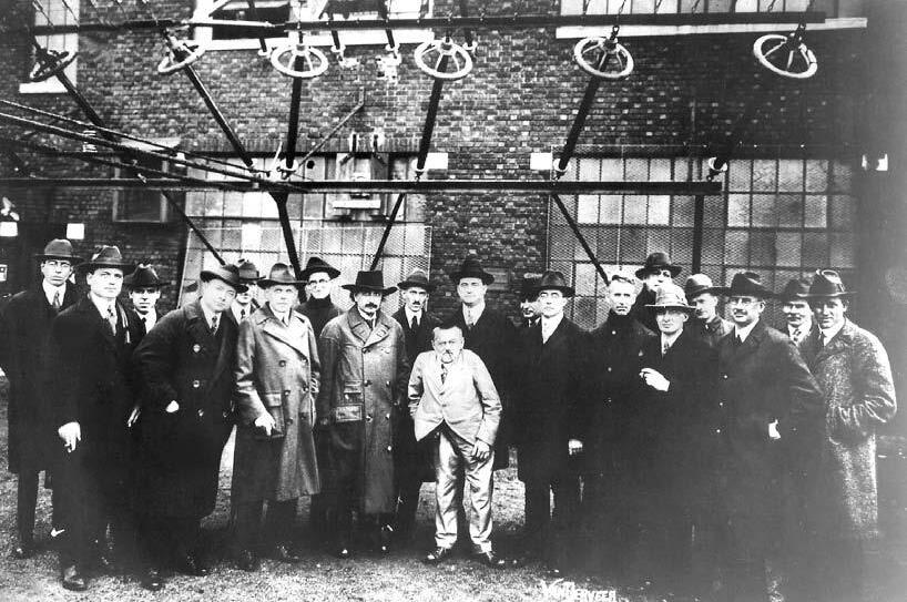
Figure 1.1 Communications pioneers—a group of distinguished scientists visiting RCA’s experimental Transoceanic Communications Station at New Brunswick, New Jersey in 1921. From left to right: (starting fourth from left) David Sarnoff, Thomas J. Hayden, Dr. E. J. Berg, S. Benedict, Albert Einstein, John Carson, Dr. Charles P. Steinmetz, Dr. Alfred N. Goldsmith, A. Malsin, Dr. Irving Langmuir, Dr. Anthony W. Hull, E.B. Pillsbury, Dr. Saul Dushman, R. H. Ranger, and Dr. G. A. Campbell. (Photo courtesy of RCA.)
T. L. Wadley Clemens Winkler
One must also not forget the many dedicated ham radio operators around the world. Some of these men were science fiction dreamers. Their contribution to this invention was that of stimulating the other’s imaginations. Still others were scientists and mathematicians. Their role was to pave the road for future developments. Some were politicians and businessmen, and some were inventors and technical practitioners, or what we usually refer to as engineers (see Figures 1.1 and 1.2).
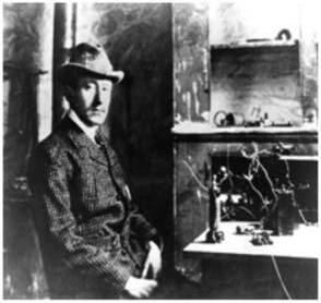
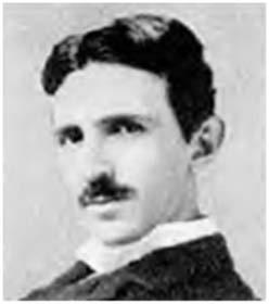
(a)
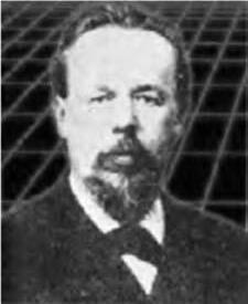
Figure 1.2 Who invented radio? (a) Italian Guglielmo Marconi and his famous receiver at St. John’s, Newfoundland, December 21, 1901, where the first transatlantic signal was heard. He performed his first RF tests in 1895 in London, allegedly copying Tesla’s invention. Marconi’s first wireless patent application was filed in England on June 2, 1896. (Photo courtesy of RCA.) (b) Croatian of Istro-Romanian origin Nikola Tesla demonstrated the first transmissions of intelligent RF signals in 1893 in the U.S. and obtained first U.S. patent #645,576. He used a 5-kW spark transmitter. Despite winning disputes with Marconi who claimed he never read Tesla’s technical papers, he is not usually thought of as the father of radio. However, Tesla invented radio.(c) Russian Alexander Popov entered the wireless field through his development of a receiver that detected thunderstorms on May 7, 1895. He conceived the idea of using the Branly coherer to pick up natural “damped” waves generated by lightning. On March 24, 1896, Popov demonstrated sending and receiving wireless signals across an 800-foot distance.
The History of Radio
The following is a brief history of the development of radio.
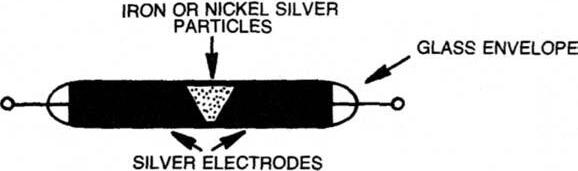
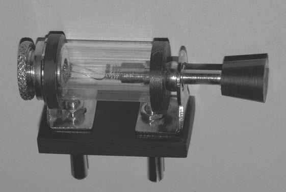
2.1 The Coherer
The radio receiver appeared as a consequence of an invention called the coherer (Figure 2.1). Edouard Branly, of France, discovered that a glass tube with two silver electrodes, filled with loose iron particles, will conduct DC electricity better in the presence of so-called Hertzian waves generated with conventional spark generators.
2.2 The First Radio Receiver
Branly would not see the real application for this device, but Marconi developed a receiver on this principle in 1895, apparently copying an earlier invention of Nikola Tesla. He applied for a patent in June of 1896. According to the records, Croatian Nikola Tesla demonstrated the first transmissions of intelligent RF signals in 1893 in the United States and obtained the first U.S. patent #645,576 for this invention. He used a 5-kW spark transmitter. Despite winning disputes with Marconi who claimed to never have read Tesla’s technical papers, he is not usually thought of as the father of radio. However, Tesla is the inventor of radio.
A Russian scientist by the name of Alexander Popov in 1895 claimed to have created a storm receiver, which rang a bell every time an electrical storm would approach within several miles. This receiver had no antenna and was of limited range.
In 1895, Marconi discovered that by adding two wires with large metal plates at the ends to his receiver and/or transmitter, the range could be increased considerably. He called these wires “catch wires,” and soon buried one of these wires in the ground, while elevating the other, thus discovering the HF antenna system as we know it today.
It appears that the two inventors were in correspondence for a while. While Popov did not see any further application for his receiver, the enterprising Marconi perfected the machine and demonstrated its usefulness. He noticed that once conducting, the coherer would stay in that state. Thus, he invented the decoherer.
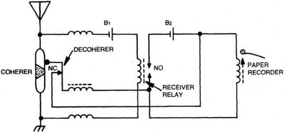
2.3 The Decoherer (Practical Coherer/Decoherer Receivers)
The decoherer was nothing more than an electrical bell, slightly modified and connected in series with the coherer and/or the receiver relay as shown in Figure 2.2. Every time a signal was received, the coherer would be set in an “on” state, triggering the relay and, therefore, the electrical bell, which in turn would knock on the coherer, resetting it for a new signal. Although practical receivers of this type required a decoherer, they were typically referred to as coherer receivers.
Marconi perfected this receiver and produced several versions of it. He left Italy and went to England where he improved the coherer, producing equipment that established maritime communications for the Royal Navy. By 1899, he established communications across the English Channel, and two years later he sent the letter “S” over the Atlantic Ocean, by using a similar receiver [see Figure 1.2(a)]. He realized the limitations of the coherer receiver, but it wasn’t until 1906 that any improvement came about.
2.4 Galena Crystal Discovery, the Fleming Valve, and the Audion
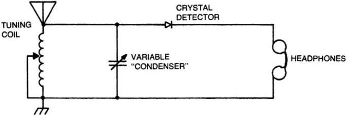
General H. H. Dunwoody of the U.S. Navy discovered the crystal detector in 1906 (see Figure 2.3). This produced a new type of receiver, which was more sensitive: the crystal, or galena, receiver (see Figure 2.4). The crystal receiver set didn’t last long as a commercial receiver type because of Fleming’s valve (1904) and the De Forest audion (1906).
Silver electrodes
Figure 2.1 The coherer was invented by Edouard Branly in 1891.
Figure 2.2 A typical coherer receiver from 1901 had an automatic decoherer.
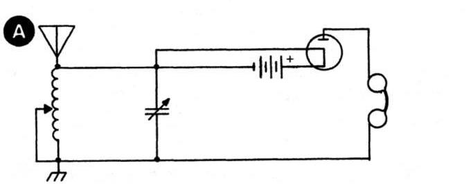
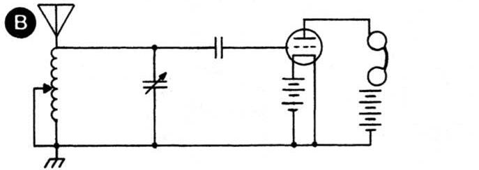
As a result of these inventions, new and even more sensitive receivers evolved from the crystal receiver as shown in Figure 2.5.
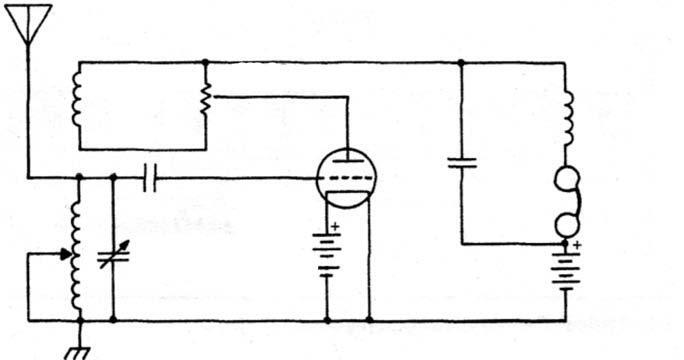
2.5 The Audion and the Regenerative Receiver
A new generation of radio receivers was born in 1906: the regenerative sets. Edwin Howard Armstrong is responsible for the invention of the regenerative receiver. He understood that the Audion circuit used in Figure 2.5(b) was not satisfactory. In this circuit, the Audion’s grid was connected in a tuned circuit to the receiver’s antenna, while the plate was connected in series with the headphones and the anode battery to ground. The circuit was closed through the electron-emitting filament, which in turn was activated by the filament battery.
Armstrong found that some alternating current was produced in the plate headphone circuit (called the wing circuit) where it wasn’t expected and attempted tuning it in much the same manner as the antenna-to-grid circuit, thus coupling some of the amplified output signal back to the grid circuit inductively, as shown in Figure 2.6. This method was called regeneration, and the “tickling” level adjustment shown in the figure provided for a threshold, allowing for large amplification
Figure 2.3 A typical commercial galena crystal detector has a well-designed “cat whisker arm.”
Figure 2.4 A typical 1906 crystal (galena) receiver.
Figure 2.5 The evolution of the crystal (galena) receiver was a result of the Fleming valve and the Audion. (a) The Fleming valve replaced the crystal detector in this 1907 receiver. (b) This receiver uses De Forest’s Audion in a detector/amplifier mode.
Figure 2.6 A typical regenerative receiver using De Forest’s Audion.
not previously possible with any other method. This newly discovered feedback amplifier circuit made practical long distance reception a reality for the first time.
2.6 The Audion and the Local Oscillator
Both Armstrong and De Forest noted that when pressing the Audion to higher amplification (by increasing the tickling level, over the threshold point) in a regenerative set, an audible hissing would result. While De Forest dismissed this fact as an “irritating noise that hindered proper operation,” Armstrong went on to prove that the Audion was not only a receiving device, but an oscillator of electromagnetic waves, which would serve later as the basis for the local oscillator (LO) to be used in the superheterodyne receiver.
2.7 The Audion and the Tuned Radio Frequency (TRF) Receiver
Another form of radio receivers characteristic of this era was the tuned radio frequency (TRF) receiver. The TRF receiver was nothing more than a chain of individually tuned amplifiers. This radio took advantage of the Audion valve in an amplifying mode. Frequently, many dials were present on these early radios and it took patience to tune one of them. Better versions employed complex mechanical tracking for slaving several variable capacitors to the motion of a single knob in order to provide identical tuning as shown in Figures 2.7, 2.8, and 2.9. These radios were popular until 1928.
However, this concept is still being used today at much higher frequencies. In its modern implementation, called the crystal video receiver it is used for high probability of intercept applications such as electronic countermeasures (ECM), primarily for detection of low-duty cycle pulses or CW signals over ultrawideband frequency ranges and in relatively close proximity to the emitters. Its purpose is near instantaneous reception of many signals over widebands without the need to sweep a local oscillator, which takes time.
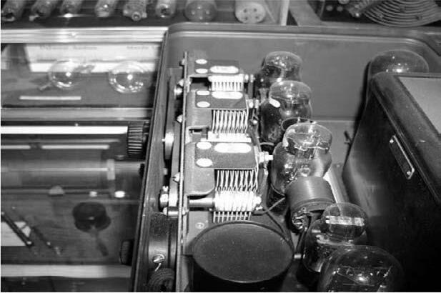
Figure 2.7 Early 1920s Atwater-Kent (AK-42) tuned radio frequency (TRF) receiver implementation using belts and variable capacitors to provide a triple tracking filter function combined with tubes for amplification. (Courtesy of the Museum of Broadcasting, Minneapolis, Minnesota.)
Detector
A typical crystal video receiver consists of a multiplexer or a power divided filter bank, which splits a wide input frequency range into several broad contiguous bands, which in turn are further filtered, logarithmically amplified, and detected. Amplitude and video detection occurs at the baseband in each of the bands using a crystal square law detector. We will discuss this type of high probability of the intercept receiver along with others in more detail in Chapter 26.
2.8 Early Progress in Radio Receivers
As a result of the early Audion invention, amplitude modulation (AM) was born, and before long the spectrum was crowded with voices and music; electromagnetic interference (EMI) finally began.
The type of radios described earlier were quite sensitive, but had very poor selectivity. Many stations were received at the same time. It is interesting to look at some statements made during this time, statements that probably define the radio receiver as we know it today.
“Imagination is better than knowledge,” said Albert Einstein, and scientists and engineers certainly had imagination during this time in history.
William Crooks, an English physicist who missed the discovery of X-rays, envisioned the progress of radio receivers. He said in 1892: “More delicate receivers
Figure 2.8 Typical TRF receiver has a triple tuned circuit.
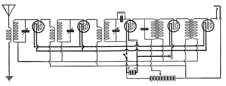
Figure 2.9 Schematic diagram of a typical TRF receiver of the 1920s.
which will respond to wavelengths between certain defined limits and be silent to all others remain to be discovered.”
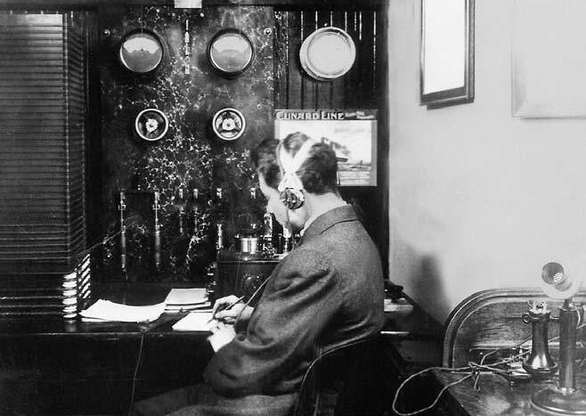
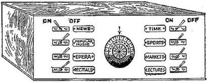
David Sarnoff (see Figure 2.10) a self-educated technical genius, entrepreneur, and a ham radio operator famous for receiving the Titanic distress message, said in 1916: “The receiver can be designed in the form of a simple radio music box and arranged for several different wavelengths, which should be changeable with the pulling of a single switch or pressing of a single button.” This vision is shown in Figure 2.11. The realization of such selective receivers did not come true until 1918, when Professor Armstrong invented the superheterodyne receiver.
receiving traffic at the John Wanamaker store in New York City in 1912. Note the Cunard Line photo on the wall. He stayed at his post for 72 hours to report the Titanic disaster, demonstrating the importance of radio and generating new interest in radio technology. Sarnoff later became the president of RCA. (Photo courtesy of RCA.)
Reference
[1] Dellinger, J. H. , and L. E. Whittemore, Lefax Radio Handbook, Washington, D.C.: Radio Laboratory, U.S. Bureau of Standards, 1922.
Figure 2.11 David Sarnoff’s vision of a futuristic receiver (1916). (From: [1].)
Figure 2.10 David Sarnoff
The Superheterodyne Receiver
The superheterodyne is a type of radio receiver that uses a process in which the incoming signal is mixed with a local oscillator (LO) signal in a manner generating new signal components, which are equal to the sum and the difference of the original frequencies. One of these products is designated as the intermediate frequency (IF) and is passed by a tuned circuit, which rejects the undesired products as well as the original incoming frequency while still maintaining the information contained in it. This low level signal (caused by the natural losses along the propagation path between the transmitting point and the receiver’s antenna) is further amplified before detection takes place. The process of mixing will be discussed in detail in Chapter 15.
In the amplitude modulation (AM) mode, the audio frequencies riding on the carrier are detected through the process of rectification, directly from the IF, while Morse code signals (CW) or single sideband signals (SSB) can be recovered by another mixing process, which produces audible heterodynes with the help of a beat frequency oscillator (BFO).
In the case of frequency modulation (FM) where the carrier frequency moves around a center point at the rate of the audio frequency, a frequency discriminator or a phase-locked loop are used for detection. The final step after detection is audio amplification.
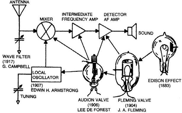
In the Armstrong superheterodyne, the audion tube performed several functions as shown in Figure 3.1. It first acted as a local oscillator (LO), which produced high frequency currents of a different frequency than the signal to be received. It was used again as a mixer when this energy was heterodyned with the incoming frequency from the antenna, producing the intermediate frequency (IF), which was amplified again by the audion. Amplitude modulation (AM) detection was performed with the help of the Fleming valve, while final audio amplification used the audion tube again. Today there are several types of superheterodynes, and their mixing schemes dictate their terminology, as shown in Table 3.1.
3.1 Single Conversions
A single conversion receiver can downconvert from the received frequency or upconvert. Both downconvert and upconvert can be used in a single conversion superheterodyne, when the range to be covered is so wide that the intermediate frequency falls somewhere in the middle of it, as in the case of many general coverage HF
(1917)
Figure 3.1 The impact of earlier inventions on the superheterodyne receiver, which was invented in 1918 by Edwin H. Armstrong.
Table 3.1 Superheterodyne Receiver Types
1. Single conversionsDownconversion; Upconversion; Combinations of both.
radio receivers with IFs at 5.5 MHz, 9 MHz, or 10.7 MHz. There are advantages and disadvantages in these schemes, as we will see later in Chapter 16.
3.2 Multiple Conversions
Another superheterodyne type is the double conversion, and as a growth from the double conversion, the triple and quadruple conversions.
3.3 Direct Conversion (Zero IF)
The last and the simplest form of superheterodyne is the direct conversion type. We will analyze all these types of radio receivers, and examine their advantages and disadvantages. Branching from this concept, we also look at the direct sampling no conversion approach, which takes advantage of modern A/D, DSP, and D/A techniques.
Ediso
effect (1883)
Implementing Single Conversion Superheterodynes
The most popular superheterodyne system ever realized was a single conversion type with an IF of 455 kHz. The block diagram in Figure 4.1 shows a typical single conversion superheterodyne, which tunes the frequency range from 500 kHz to 30 MHz. The IF amplifier is tuned to 455 kHz.
The incoming signal anywhere between 500 kHz to 30 MHz passes through a tunable filter called the preselector. The preselector has the role of filtering out all frequencies coming from the antenna, except for the one that is needed. This filtered signal goes to the mixer, which can take several forms, where it combines with the frequency coming from the local oscillator (in our case a variable frequency oscillator) and produces an IF signal at 455 kHz.
As you have probably already noticed, this is a downconversion scheme because the IF falls below all of the frequencies to be received within the range of 500 kHz to 30 MHz. The variable frequency oscillator (VFO) LO is operating 455-kHz above the incoming frequency at all times. For example, if we want to receive 500 kHz, the VFO must generate 955 kHz, and if we want to receive 30 MHz, the VFO should be 30.455 MHz.
As a result of the interaction between the VFO and the signal, there are two signals (referred to as products) coming out of our mixer: the sum and the difference (other products are generated as a result of the mixing and they will be reviewed later in this book). The higher product is rejected by the IF filter tuned to 455 kHz.
Note that no matter where we tune the receiver, the IF is always the same, making filtering and processing of the signal identical for all RF input frequencies to be received.
This is the major idea behind the superheterodyne approach. Mixers will be discussed in detail in Chapter 15. Unlike the previously used tunable filters in the TRF receiver, any input frequency can simply be reduced to a common denominator, the IF, and can be processed through a single fixed frequency filter with a bandwidth matching the information bandwidth and a set of amplifiers, which are optimized at a single frequency (the IF) and easier to handle. This is why the superheterodyne has lasted until now as the best design.
The 455-kHz signal, which also contains the information that came from the antenna, is filtered and amplified in the IF amplifier and is finally detected and amplified again at audio frequency before being delivered to the speaker. This scheme remains, to date, a basic approach of the singIe conversion downconvert
500 kHz
30 MHz
Figure 4.1 Simple block diagram of a general coverage single conversion superheterodyne receiver. Note that the preselector tracks together with the local oscillator (LO).
superheterodyne receiver. Note the tracking mechanism of the scheme (Figure 4.2). In this type of radio, it is imperative that the preselector and the VFO track together. Because of the large RF input bandwidth of six octaves, it becomes very difficult to provide proper preselection with a single filter.
In a basic single conversion HF receiver covering 500 kHz to 30 MHz, the incoming signal goes through separate filters, which are switched in and out for different ranges, one at the time, allowing for several bands to be covered in steps. The VFO is also switched in similar bands, which track exactly with the preselector bands.
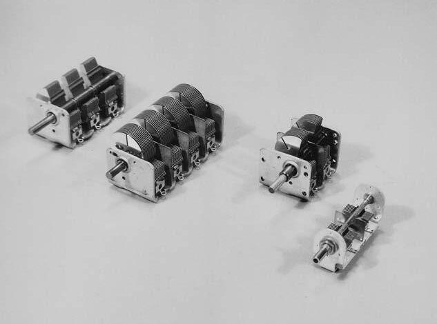
The tuning element of the preselector, the variable capacitor, is mechanically ganged with the VFO capacitor. They track together, so that when the preselector peaks at some frequency, the VFO operates exactly 455 kHz above that frequency, as shown before. For example, if the preselector is tuned to exactly 1 MHz, its capacitor is mechanically ganged with the VFO capacitor, so that the VFO produces exactly 1.455 MHz. The rest of the circuitry remains the same, as described previously. However, we have a new problem, the image. This is shown in Figure 4.3. Tracking variable capacitors used in such receivers are shown in Figure 4.4.
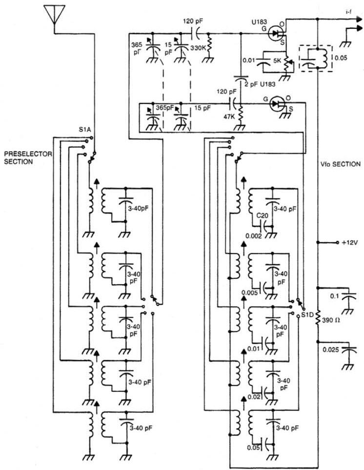
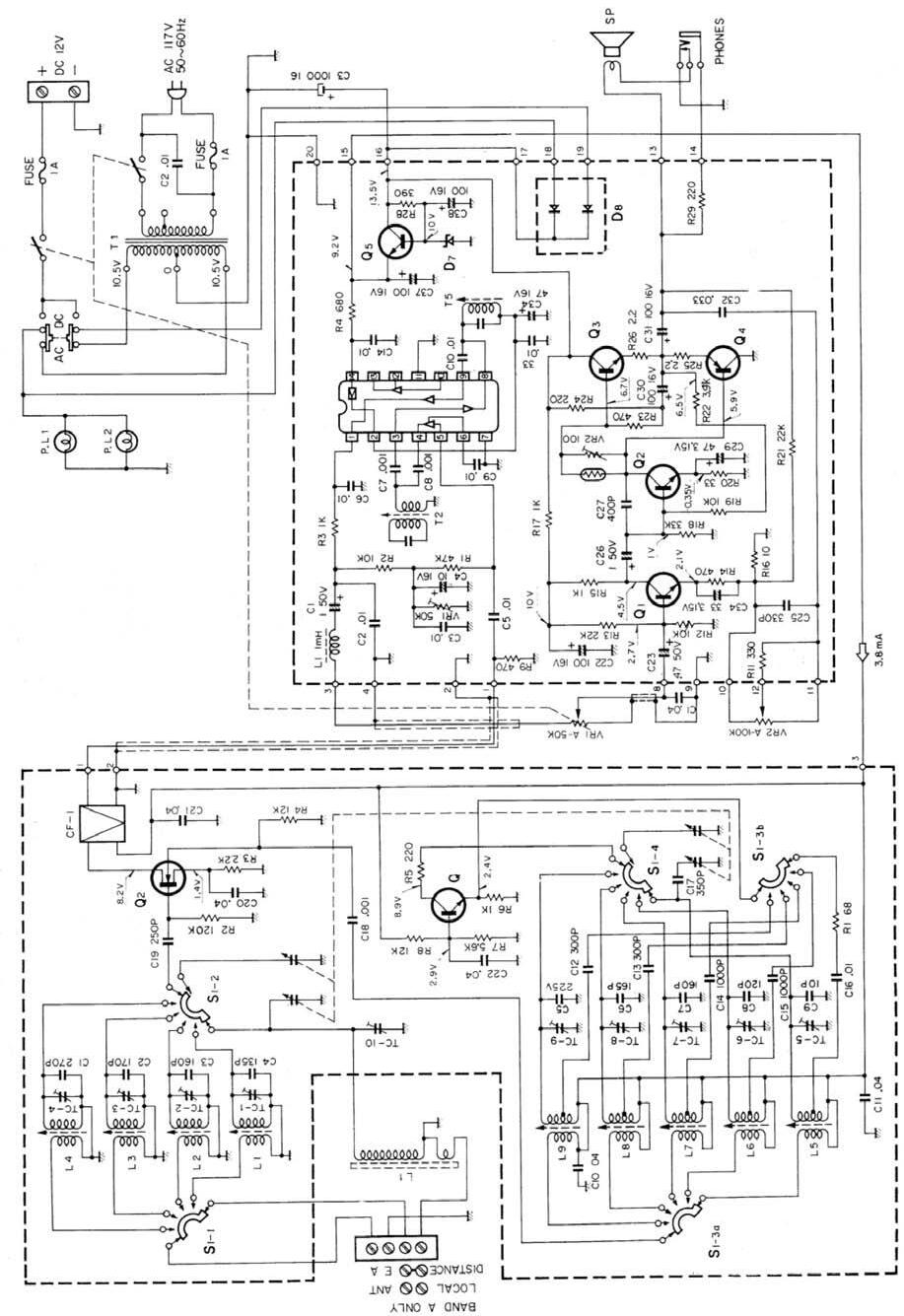
A practical five-band receiver could be implemented as shown in the schematic diagram in Figure 4.5. In this design, the signal from the antenna goes to switch S11, which couples it with any one of the five preselector tuned circuits, corresponding to the five bands in this case. Switch S1-2, which is mechanically ganged with S1-1, picks up the output of the preselector range chosen. Together with the variable capacitor, which is always in the circuit, the chosen range tracks the exact frequency to be received, which is exactly 455-kHz below the frequency of the VFO.
The VFO capacitor is mechanically coupled with the preselector capacitor. S1-3A and S1-4 are also mechanically connected with S1-1 and S1-2 in order to provide the right ranges for the VFO to match the preselecctor. The VFO signal couples through C18 into Q2 where it combines with the proper preselected signal and produces a difference frequency of exactly 455 kHz for any selected receiver frequency between 500 kHz and 30 MHz.
The signal is directed through a ceramic filter, which eliminates all the unwanted mixing products and keeps only the 455-kHz signal. This signal is then routed
Figure 4.2 Classic implementation of a tracking mechanism for a preselector and a variable frequency oscillator, showing a complex band selector in a standard 455-kHz IF receiver.
through a chain of amplifiers; demodulated; fed through a volume control into an audio amplifier made of Q1, Q2, Q3, and Q4 (circuit board #2); and finally moves into the speaker.
By now, some readers have probably wondered why 455 kHz was the choice for the IF. Is there anything special about this frequency? There are three reasons for this choice:
• It was right below the broadcast band.
Mixer
Detector
1,455 kHz F(station creating an image) = F(RX)±2 x (IF)
In a 455-kHz IF downconversionreceiver, an image will be created by any stations 910 kHz above the frequency being received (+3dB image noise content).
Figure 4.3 Tracking system: a 455-kHz IF, downconvert AM superheterodyne receiver. The image is introduced by the low frequency IF.
Figure 4.4 Modern variable capacitors featuring as many as four tracking sections have been used in AM and HF superheterodyne receivers.
• It was low enough in frequency to allow adequate selectivity to be obtained with conventional inductors and capacitors (L/C).
• It was empirically found that using this IF frequency, the image was kept out of a standard AM receiver. 455 kHz IF Amp
4.5 Modern solid-state implementation of a general coverage 455-kHz IF, single conversion superheterodyne receiver.