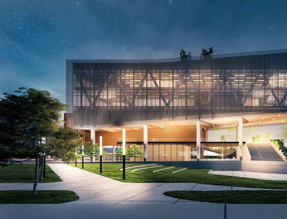
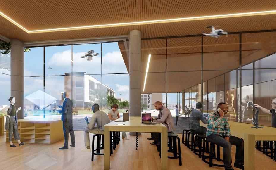
PROPEL LEARNING CENTER
Site: Atlanta GA, US Feb 2021
Role: Designer/Modeling/Rendering
https://www.apple.com/newsroom/2021/01/apple-launches-major-new-racial-equity-and-justice-initiative-projects-to-challenge-systemic-racism-advance-racial-equity-nationwide/
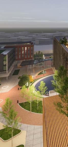
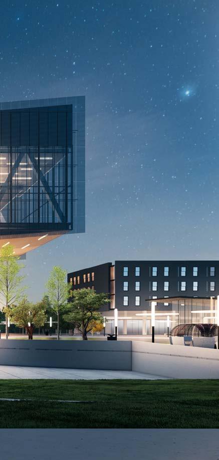
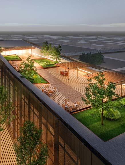
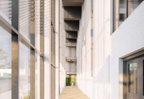
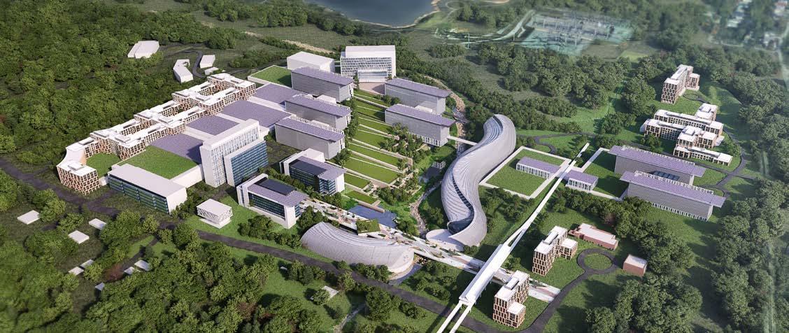
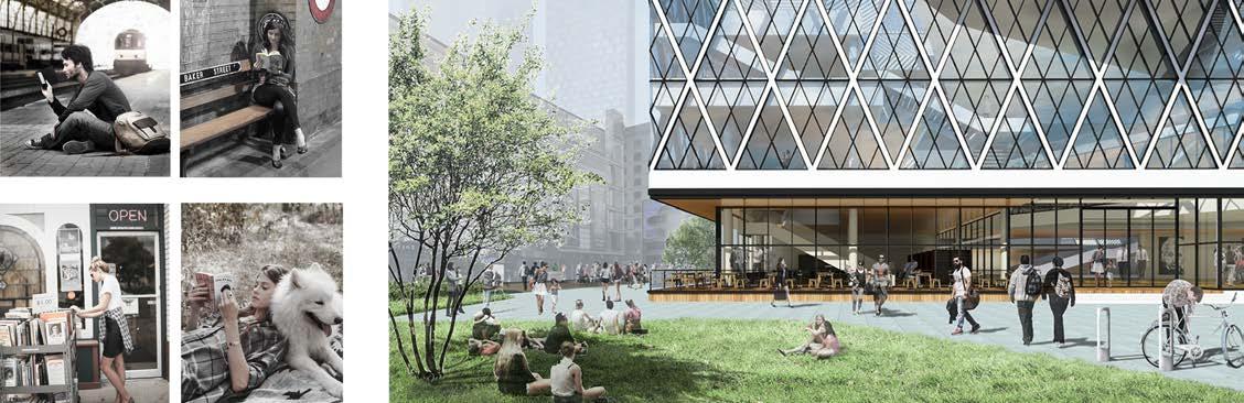
Concept design of a new digital learning hub, business incubator and global innovation headquarters in Atlanta for students of historically black colleges and universities (HBCUs).
Site: Las Vegas, NV, US
Jun 2022 - Aprl 2023
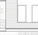
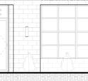
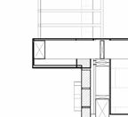
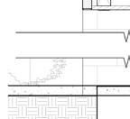
Role: ATL office project leader, Drafter (DD, CD, part of CA)
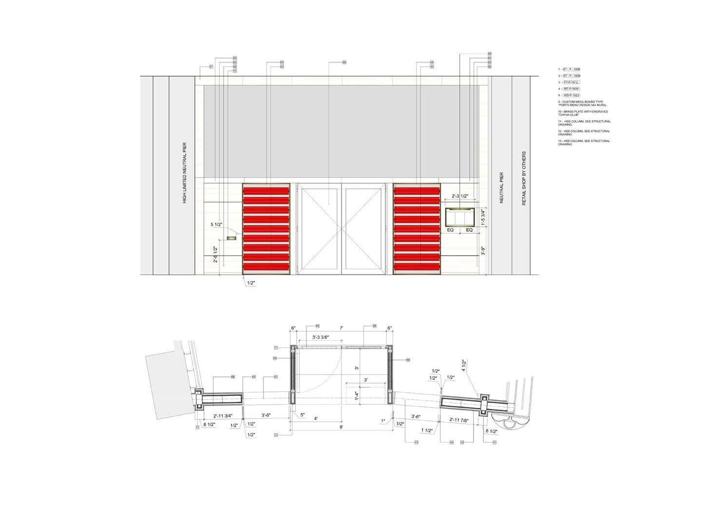
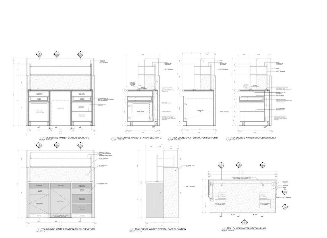
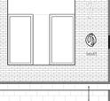
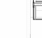
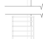
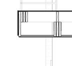
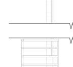
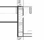
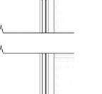
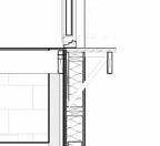
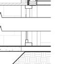
L3_2.A4.04 3 L3_2.A4.00 12.6 12.7 13.3 13.7 L3_2.A4.08 5 4 L3_2.A4.13 2 5 3 L3_2.A4.04 2 G6.C2 F2 G6.2 G6.C G6.C2 G6.2 G2.C2 G6.2 G2.C2 G6.C2 G6.C2 G6.2 L3_2.A4.11 1 2 4 3 L3_2.A4.12 1 2 3 4 L3_2.A4.06 1 L3_2.A4.07 L3_2.A4.07 L3_2.A4.10 L3_2.A4.10 L3_2.A4.10 5 4 F6.B G6.C 0' 3 1/4" +/- 2' 1" 0' 9 3/4" 31' 7/8" 1' 1/2" 20' 5/8" F2 7' 2" 7' 2" 8' 6 1/4" 2 L3_2.A4.00 L3_2.A4.00 L3_2.A4.00 L3_2.A4.01 L3_2.A4.01 KK L3_2.A4.02 KK L3_2.A4.02 LL L3_2.A4.02 LL L3_2.A4.02 QQ L3_2.A4.02 QQ L3_2.A4.02 L3_2.A4.02 RR L3_2.A4.02 L3_2.A4.02 UU L3_2.A4.02 L3_2.A4.02 VV L3_2.A4.02 THE CONSERVATORY 1602 TEA LOUNGE 1603 THE GARDEN 1601 NORTH DINING ROOM 1610 N. ADA TOILET 1613 UTILITY STORAGE 1618 SOUTH DINING ROOM 1611 MAIN BAR 1612 THE GARDEN LOUNGE 1609 S. ADA TOILET 1614 1613 1614 1611 1602 THE GATE 1600 SOMMELIER STATION 1615B G6.C L3_2.A7.04 L3_2.A7.05 L3_2.A7.02 2 L3_2.A7.14 L3_2.A7.09 NOTE: RECESSED SLABSEE FLOOR FINISH TRANSITION DETAILS SHEET C L3_2.A7.60 7' 11" 1' 11 3/4" 0' 1/2'' 0' 1/2'' NOTE: BAR IS SHOWN FOR REFERENCE ONLY. SEE FOOD SERVICE DRAWINGS FOR DETAILED INFORMATION CL C C CL L3_2.A6.21 SIM L3_2.A6.21 1 SIM F6.A G6.C2 F6.A G2.C2 1' 1/4" 1' 1/4" 1' 9 1/4" 1' 1/2" FIXED LEAF, MAINTAINENCE USE ONLY 1600 16' 5 3/8" 0' 8" 6' 5 3/8" C L3_2.A7.60 DOOR ON HOLD OPEN DURING VENUE OPERATION L3_2.A7.17 1 13 3 13 L3_2.A4.09L3_2.A4.091 6 5 4 3 6 4 7 10 L3_2.A7.09 2 L3_2.A7.17 SIM. 3' 10 5/8" 1' 1/8" 8 1/4" G2.C3 G2.C3 7' 9 7/8" 0' 3 1/4" 39' 2 3/4" 6' 5" 7' 1/2" 1' 1" 1' 0" 1' 0" 3' 1/2" 18'' FROM FINISH EQ EQ 7' 1/2" 1' 7" 0' 3/8" 4' 1/4" 5/8" EQ EQ 31' 7/8" 0' 3 1/4" 11' 0" 11' 0" TO FINISH TO FINISH 3' 1" 0' 7" 0' 7" 3' 1" 3' 1" 0' 7" 3' 1/2" 7' 1/2" 13' 7/8" 0' 7" 3' 1" 3' 0" 4' 6 5/8" 0' 1 1/8" 25' 1/2" 0' 7" 16' 1/2" 0' 3/8" L3_2.A7.07 WAITER STATION WAITER STATION FUTURE PDR PARTITION LEGEND EXISTING PARTITION NEW UNRATED PARTITION Template Version Sheet Size: 30" x 42" B M 6 L A F b L C y C b R 2 v 2 2 3 7 0 M 2022_05_12.0 © 2022 Hamilton Anderson Assoc., Inc 2 4 1 2 1 2 3 4 5 1 2 3 4 5 return air through cornice slot return air through cornice slot return air through cornice slot return air through cornice slot return air through cornice slot extract through celing slot extract through ceiling slot Possible High Voltage panel location panel location Possible electrical panel location WC SINK WC SINK TABLE CEILING CEILING CORRIDOR TABLE TABLE TABLE TABLE ENTRANCE DOOR EQEQ PANEL PANEL PANEL PANEL ARCH CORRIDOR EQ EQ EQ EQ EQ EQ EQ EQ EQ EQ CEILING CEILING PANEL CORRIDOR CORRIDOR CORRIDOR EQ EQ EQ EQ ARCH ARCH CL CL CL C C C CL C CL C C C CL C CL CL CL CL CL C C CL CL CL C C CL C CL T22 12.6 12.7 12.8 13.3 13.7 H.2 H.3 GM H.5 H.6 GN H.8 J COLD STOR. 16F L3_2.A4.00 2 L3_2.A4.00 L3_2.A4.00 L3_2.A4.00 L3_2.A4.00 4 L3_2.A4.00 L3_2.A4.01 L3_2.A4.01 L3_2.A4.01 2 L3_2.A4.01 KK L3_2.A4.02 KK L3_2.A4.02 LL L3_2.A4.02 LL L3_2.A4.02 QQ L3_2.A4.02 QQ L3_2.A4.02 RR L3_2.A4.02 RR L3_2.A4.02 UU L3_2.A4.02 UU L3_2.A4.02 VV L3_2.A4.02 VV L3_2.A4.02 L3_2.A4.13 L3_2.A4.13 8 L3_2.A4.08 L3_2.A4.05 1 L3_2.A4.09 L3_2.A4.12 5 L3_2.A4.11 5 L3_2.A4.03 POS POS POS 180 POS POS POS 180 POS 180 13' -2''A.F.F 10' -2''A.F.F 14' A.F.F 12' -10'' A.F.F 15' -7 1/4'' A.F.F 12' -10'' A.F.F 14' -8 1/2'' A.F.F 16' -7 1/2'' A.F.F --WD- -1638 --PT- -1610 PT-P-1604 --WD-P-1617 PT- -1604 --PT- -1610 ----PT-P-1612 --SPF- -1602 TEA LOUNGE 1603 THE CONSERVATORY 1602 NORTH DINING ROOM 1610 THE GARDEN LOUNGE 1609 SOUTH DINING ROOM 1611 MAIN BAR 1612 S. ADA TOILET 1614 N. ADA TOILET 1613 UTILITY STORAGE 1618 BOH CORRIDOR 1619 MAIN KITCHEN 1617 WASH AREA 1617D DRY STORAGE 1617E THE GARDEN 1601 GL- -1606 -8' 5 5/8" 0' 10" 16' 2 1/8" 0' 10" CL 0' 10" 0' 10" EQ C 3' 8 1/2" 10" EQ D EQ D 4' 10" 0' 10" EQ B 0' 10" EQ B 0' 10" 0' 10" 4' 0'' EQ A 0' 10" EQ A 10" EQ 0' 10" EQ 0' 10" EQ A 0' 10" EQ EQ L CL 0' 10" 10" 0' 10" 0' 10" 0' 10" 0' 10" 4' 1/2" 0" EQ EQ /ROOM /ROOM EQ EQ EQ EQ 4' 11 1/2" E E E E 1' 3 1/2" EQ EQ T T T T T T T T T T CENTER ON MOUNTED ABOVE GLASS CEILING T 6'' FROM COENER 4'' FROM COENER COORDINATE WITH MILLWORKCENTER ON SIDE SASH OF PANEL 6'' FROM WALL EDGE ALIGN WITH LIGHT SWITCH 6'' FROM CORNER LED12 S47 S47 S47 S46 S46 S47 S47 S47 S47 S47 S47 S47 S47 S47 S47 S4723' 4 1/8" 16' 3/4" 14' 1 5/8'' A.F.F 14' 5/8'' A.F.F 0' 11 1/4" 14' 9" CENTER OF CIRCULAR CL 0' 6" NIB WALL 5" 0' 8" 0' 11" L C EQ EQ EQEQ 0' 7" 0' 7" CL 0' 11" +8' - 0" AFF+10' - 0" AFFPOS WP+10' - 0" AFF-+15' - 6" AFF-+16' - 4" AFF +15' - 8" AFF+15' - 10" AFF +16' - 4" AFF+16' - 0" AFF+14' - 6" AFF +16' - 6" AFF-C 2 L3_2.A7.44 L3_2.A4.14 2 EXPANSION PDR 0' 8" 0' 2" 5' 2 1/8" 0' 8" 18' 9" 0' 8" 7' 2 3/4" 0' 2" 0' 8" 1' 0" 0' 8" 10' 2 3/8" 9' 5" 8" 17' -0'' A.F.F CEILING PLAN LEGEND 2X2 LAY-IN CEILING LIGHT, RE: ELEC GYP. BOARDSUPPLY DIFFUSER RETURN DIFFUSER EXHAUST EXIT LIGHTING W/ DIRECTIONAL ARROWS (SHADED AREAS INDICATE FACE) (SHADED AREAS INDICATE FACE) EXIT LIGHTING (SHADED AREA INDICATES FACE) STRIP LIGHTING PENDENT LIGHT FIXTURE, SEE LIGHTING PAN TILT ZOOM (PTZ) CAMERA,SEE IT/SECURITY FIXED CAMERA,SEE IT/SECURITY LIGHTING FIXTURE D1 D2 D3 D4 D5 D6 (SEE LIGHTING RCP) LIGHTING FIXTURE PL1 (SEE LIGHTING RCP) LIGHTING FIXTURE P2 LIGHTING FIXTURE P1 LIGHTING FIXTURE TSP1 LIGHTING FIXTURE PL6 & PL7 (SEE LIGHTING RCP) AV DEVICE LEGEND S47 NOTE: SEE AV DRAWING SETS FOR THEIR DEVICE COMPLETE DETAILS S46 S48 LED12 CEILING PLAN FINISH LEGEND Template Version Sheet Size: 30" x 42" B M 6 o a V s A F b e a L h C u R 0 6 2 3 9 1 P M 2022_05_12.0 © 2022 Hamilton Anderson Assoc., Inc 1/4" = 1'-0" L3_2.A4.00 1 REFLECTED CEILING PLAN 2 4 2 1 2 WOOD SOFFIT @7'-2'' AFF TRELLIS ABOVE ENTRY SOFFIT FUTURE PDR B 5 © 2022 Hamilton Anderson Assoc., Inc B M F F L C C R 6 0 3 M © 2022 Hamilton Anderson Assoc., Inc Template Version Sheet Size: 30" B M 3 0 F n e b e u a V g s F n e e a u L V C h n C b R 2 2 1 v 5 6 0 3 0 5 P M 2022_05_12.0 © 2022 Hamilton Anderson Assoc., Inc FONTAINEBLEAU - CHYNA CLUB DOCUMENTATION
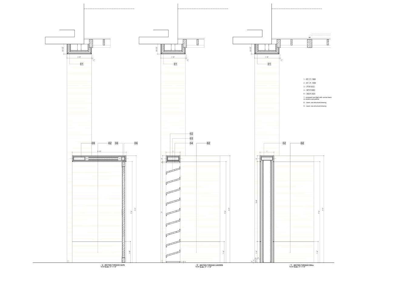

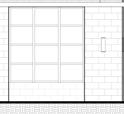
L3_2.A7.38 FONTAINEBLEAU L3_2.A7.38 LAS VEGAS, NV 89189 FONTAINEBLEAU LAS VEGAS L3_2.A7.38 BRASS Client Key Plan L3_2.A7.38 LAS VEGAS, NV 89189 FONTAINEBLEAU LAS VEGAS 1 L3_2.A7.03 1 L3_2.A7.03 2 L3_2.A7.03 2 L3_2.A7.03 3 L3_2.A7.03 3 L3_2.A7.03 Drawing No: Signature: ______________________________________ L3_2.A7.02 1 L3_2.A7.02 FRONT GATE PLAN 1 1/2''=1'-0'' Template Version Sheet Size: 30" 42" M 6 o b e a e s A F n a n e u L h a C 2 2 v 6 2 3 4 3 5 P M 2022_05_12.0 © 2022 Hamilton Anderson Assoc., Inc 3 L3_2.A7.02 SECTION THROUGH GATE 2 L3_2.A7.02 SECTION THROUGH LOUVERS 1'-1/2'' = 1'-0'' 1'-1/2'' = 1'-0''
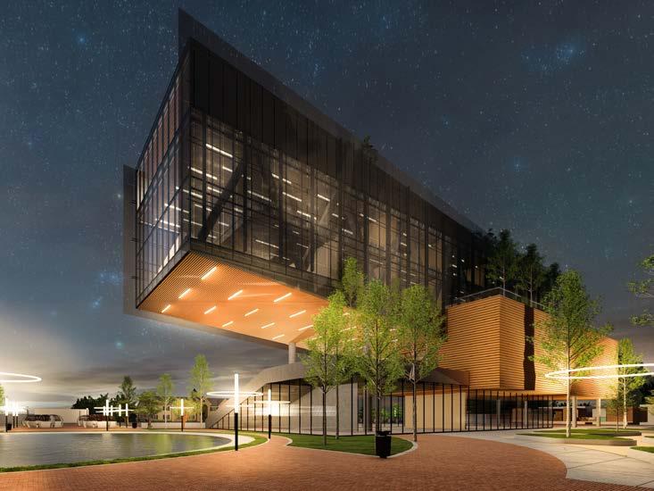
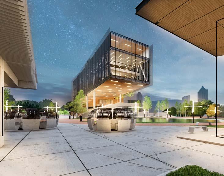
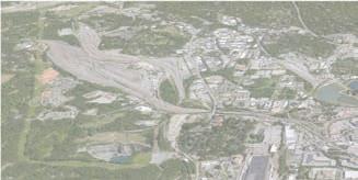
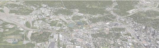
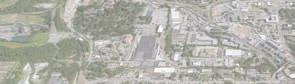
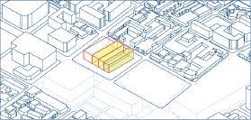
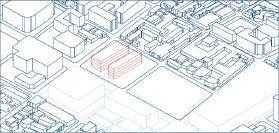
CENTENNIAL YARD CONCEPT DESIGN (2020)
Site: Atlanta GA, US
Feb 2020 - Aug 2021
Role: Designer/Modeling/Layout
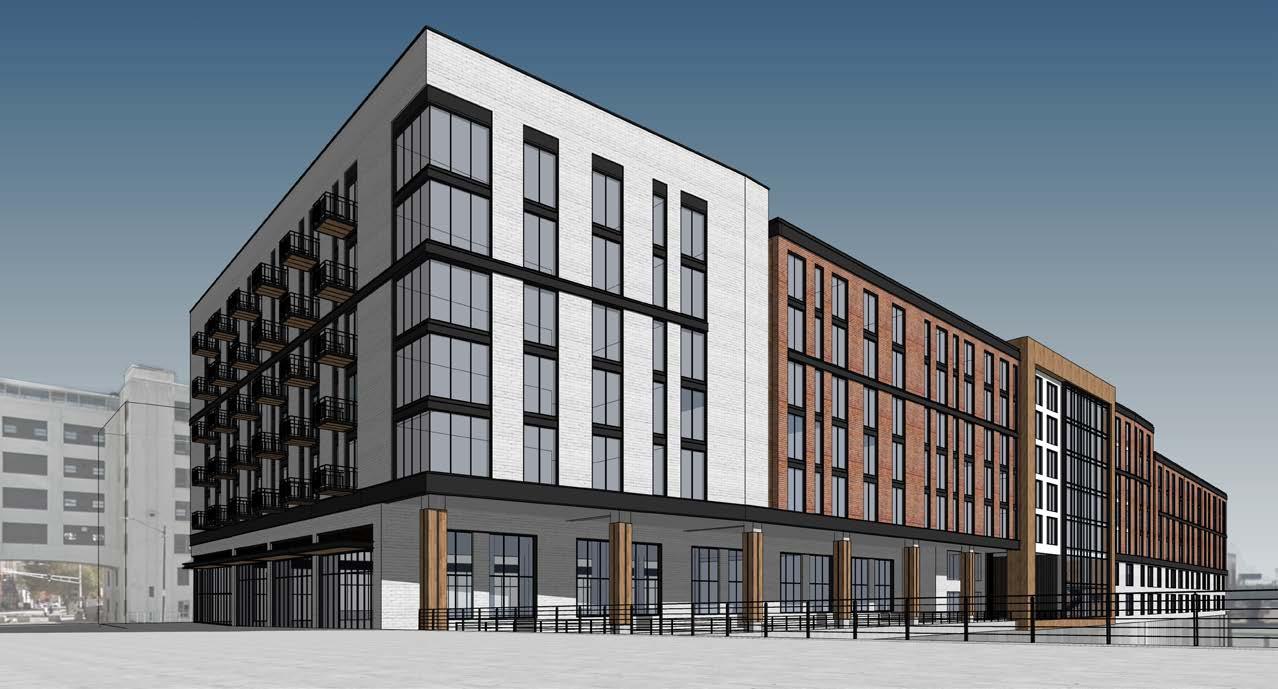
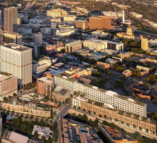
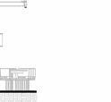
The Centennial Yards Spring Street Phase II project is part of a 6.14 acre proposed mixed use development located area of Atlanta known as the Gulch. This mixed-use multifamily building consists of 232 residential units, amenities, There are 5 levels of residential units over a 2 level commercial / residential podium over a 2 level parking garage. elevation complexities that requires a multi - level approach for pedestrians and vehicles. The building is bordered active railway at the lowest garage level, on the East by a street / podium level pedestrian bridge, on the West by a street vehicular bridge and on the South by a podium level elevated green space / courtyard across from the existing Norfolk idential building. The building aesthetic resonates with the existing context of the Norfolk Southern buildings along the existing context of the historic Castleberry hills.
WH WH 7' 0" 12' 6" 1B UNIT A (699 27' 5" - 0 8' 0" 6' 6" 3' 6" 3' 0" 14' 0" 15' 0" 1B-UNIT A (V) (853 SF) 29' 0" 6' 6" 10" 6' 6" 11' 8" 5' 6" 5' 0" 0' 2" 3' 10" 3' 0" 5' 0" 11' 0" 13' 4" 1B- UNIT A (EJ) (699 SF) 10" 4' 12' 0" 27' 5" TYPICAL 1 BED TYPE A TYPICAL 1 BED / 1 BATH (ON VIADUCT LEVEL) TYPE A (V) 1 BED / 1 BATH (ON EXPANSION JOINT) TYPE A (EJ) 6 10 11 12 13 14 N WH WH WH LIVING ROOM BEDROOM 7' 0" 5' 0" 3' 0" 3' 0" 5' 0" 12' 6" 12' 6" 1B UNIT A (699 SF) 27' 5" 12' 0" 4' 10" 58' 0" 6' 6" 3' 6" 3' 0" 14' 0" 15' 0" 1B-UNIT A (V) (853 SF) 29' 0" 6' 6" 10" 6' 6" 11' 8" BEDROOM LIVING ROOM 5' 6" 5' 0" 0' 2" 3' 10" 3' 0" 5' 0" 11' 0" 13' 4" 1B- UNIT A (EJ) (699 SF) 10" 4' 12' 0" 27' 5" TYPICAL 1 BED / 1 BATH TYPE A TYPICAL 1 BED / 1 BATH (ON VIADUCT LEVEL) TYPE A (V) 1 BED / 1 BATH (ON EXPANSION JOINT) TYPE A (EJ) KEY PLAN 3 10 11 12 13 14 15 16 17 18 3 10 11 12 13 14 15 16 17 18 D N D N SCOPE DOCUMENTS The Contract Documents Issued for [Conceptual Design, Schematic Design, Design Development, Partial Construction Do Issuance up to Issued for Construction] are intended to be at that level of development and as such, may be neither complete no [Construction Manager, Contractor, Design/Builder] is responsible for complete and coordinated pricing [and execution] of the Work, and shall include items necessary for the proper execution an completion of the Work, as shown, specified, reasonably inferred or equired for complete Project.For Work of delegated designs; systems, ass components and materials shall comply with national state and local code requirements.The [Construction Manager, Contractor, Design/Builder] shall inform the Owner and Architect, in timely fashion, of any discovered omissions, inconsistencies or errors the Contrac Drawn By Approved By Project No. Date Drawing No. NOT ISSUED FOR CONSTRUCTION P:\The Spur\05_DD\11262019\UnitPlans_11262019.rvt 1 2 7 0 9 2 8 7 A M PROJECT NUMBER: 201904.00 PROJECT NAME: 99 125 TE TURNER DRIVE PHASE SHEET NUMBER: A3.01 UNIT PLANS BED BATH 12/06/19 201904.00 A3.01 99 & 125 TED TURNER DRIVE PHASE II UNIT PLANS 1 BED 1 BATH RESIDENTIAL BUILDING ISSUANCES No.Drawing Issue DescriptionDate 1Updated SD Submission 12/6/2019 SCALE: 1/4" 1'-0" A3.01 1 1 BED / 1 BATH WH WH WH LIVING ROOM BEDROOM 7' 0" 5' 0" 0" 3' 0" 5' 0" 12' 6" 12' 6" 1B UNIT A (699 SF) 27' 5" 12' 0" 4' 10" - 0 8' 0" 6' 6" 3' 3' 0" 14' 0" 15' 0" 1B-UNIT A (V) (853 SF) 29' 0" 6' 6" 10" 6' 6" 11' 8" BEDROOM LIVING ROOM 5' 6" 5' 0" 0' 2" 3' 10" 3' 0" 5' 0" 11' 0" 13' 4" 1B- UNIT A (EJ) (699 SF) 10" 4' 12' 0" 27' 5" TYPICAL 1 BED / 1 BATH TYPE A TYPICAL 1 BED / 1 BATH (ON VIADUCT LEVEL) TYPE A (V) 1 BED / 1 BATH (ON EXPANSION JOINT) TYPE A (EJ) KEY PLAN 4 5 10 11 12 13 14 15 16 17 18 4 5 10 11 12 13 14 15 16 17 18 D N D N SCOPE DOCUMENTS The Contract Issued for [Conceptual Desig Schematic Design, Design Development, Partial Construction Do Issuance up Issued for Construction] are intended to be at that level of development and as such, may be neither complete no [Construction Manager, Contractor, Design/Builder] is responsible for complete and coordinated pricing [and execution] of the Work, and shall include items necessary for the proper execution an completion the Work, as shown, specified, reasonably inferred or equired for complete Project.For Work of delegated designs; systems, ass components and materials shall comply with national state and local code requirements.The [Construction Manager, Contractor, Design/Builder] shall inform the Owner and Architect, in timely fashion, of any discovered omissions, inconsistencies or errors in the Contrac Drawn By Approved By Project No. Date Drawing No. NOT ISSUED FOR CONSTRUCTION P:\The Spur\05_DD\11262019\UnitPlans_11262019.rvt 1 2 7 0 9 2 8 7 A M PROJECT NUMBER: 201904.00 PROJECT NAME: 99 125 TE TURNER DRIVE PHASE SHEET NUMBER: A3.01 UNIT PLANS BED BATH 12/06/19 201904.00 A3.01 99 & 125 TED TURNER DRIVE PHASE II UNIT PLANS 1 BED 1 BATH RESIDENTIAL BUILDING ISSUANCES No.Drawing Issue DescriptionDate 1Updated SD Submission 12/6/2019 SCALE: 1/4" 1'-0" A3.01 1 1 BED 1 BATH WH WH WH 24' 10" 3' 0" 3' 6" 13' 2" 1' 3" AHU W/D 13' 2" 13' 9" 6" 8' 8' 1/2" 23' 1/2" 14' 1/2" 16' 6" 17' 6" 9' 9" 6" 5' 0" 11' 0" 1B- UNIT G (714 SF) CORNER - 1 BED / 1 BATH TYPE G UNIT E (775 SF) 1 BED 0" 0" 3' 6" 5" 6' 6" 7' 0" 6' 7" 5' 0" W/D AHU 9' 0" 1B-UNIT H (691 SF) CORNER - 1 BED TYPE H 5' 9" 9' 3" 3 10 11 12 13 H M P T h S p 5 D D 1 6 0 1 U n P a n 1 6 2 1 1 7 2 0 9 1 2 3 8 3 A M PROJECT NUMBER: 201904.00 PROJECT NAME: 99 & 125 TE D TURNER DRIVE PHASE SHEET NUMBER: A3.02 UNIT PLANS CORNER BED BATH WH WH WH WH 24' 10" 300 9700 19' 6" 14' 4" 11' 1/2" 9' 0" 13' 2" 3" LIVING ROOM 6" 6" 1/2" 6' 3" 10' 3" 13' 2" 23' 1/2" 14' 1/2" BEDROOM 16' 6" 17' 6" 9' 9" 9' 9" 3' 6" 5' 0" 11' 0" 6' 0" 8' 11" 11' 0" 14' 0" 1B- UNIT G (714 SF) CORNER - 1 BED / 1 BATH TYPE G 1B-UNIT F (852 SF) CORNER - 1 BED / 1 BATH TYPE F 1B- UNIT E (775 SF) CORNER - 1 BED / 1 BATH TYPE E 0" 6' 0" KEY PLAN LIVING ROOM 3' 0" 3' 6" 4' 5" 6" 7' 0" 6' 7" 5' 0" 1' 3" 19' 6" 15' 5" 20' 8" W/D 1B-UNIT H (691 SF) CORNER - 1 BED / 1 BATH TYPE H 9' 3" C M C M The Contract Documents Issued for [Conceptual Design, Schematic Design, Design Development, Partial Construction Documents or Other Issuance up to Issued for Construction] are intende development and as such, may be neither complete no coordinated.The [Construction Manager, Contractor, Design/Builder] is responsible for complete and coordinated pricing [and execution] of include items necessary for the proper execution an completion of the Work, as shown, specified, reasonably inferred or equired for complete Project.For Work of delegated designs; systems, assemblies, components and materials shall comply with national state and local code requirements.The [Construction Manager, Contractor, Design/Builder] shall inform the Owner and Architect, timely fashion, of any discovered omissions, inconsistencies or errors in the Contrac Documents. Drawn By Approved By Project No. S u 5 D D 1 2 6 0 9 U P a s 1 1 6 0 9 1 1 3 3 A M NUMBER: 201904.00 PROJECT NAME: 99 & 125 TE D TURNER DRIVE PHASE NUMBER: A3.02 UNIT PLANS CORNER BED BATH 12/06/19 201904.00 A3.02 99 & 125 TED TURNER DRIVE PHASE II UNIT PLANS CORNER 1 BED 1 BATH RESIDENTIAL BUILDING ISSUANCES No.Drawing Issue DescriptionDate 1Updated SD Submission 1 CORNER 1 BED 1 BATH NOTE: Current corner 1 Bedroom unit layout to be adjusted to make apartment into 2 bedroom 2 bath unit. WH 24' 10" 8300 5' 0" 13' 2" W/D AHU 16' 6" 6" 5' 0" 11' 0" 11" 14' 0" 1B-UNIT F (852 SF) CORNER - 1 BED / 1 BATH TYPE F 3' 0" 6' 0" KEY PLAN 9' 3" 5 10 11 N WH WH WH 24' 10" 8300 13' 2" 3" LIVING ROOM AHU 6" 6" 9 1/2" 6' 3" 10' 3" 13' 2" 23' 1/2" 14' 1/2" W/D BEDROOM 16' 6" 17' 6" 9' 9" 9' 9" 3' 6" 5' 0" 11' 6' 0" 11" 11' 0" 14' 0" 1B- UNIT G (714 SF) CORNER - 1 BED / 1 BATH TYPE G 1B-UNIT F (852 SF) CORNER - 1 BED / 1 BATH TYPE F 1B- UNIT E (775 SF) CORNER - 1 BED TYPE E 0" 6' 3' 0" 3' 6" 5" 6" 7' 0" 6' 5' 0" 20' 8" W/D 9' 0" 1B-UNIT H (691 SF) CORNER - 1 BED TYPE H 5' 9" 9' 3" 1 9 10 11 12 13 C M 9 U P a s 1 1 6 0 1 PROJECT NAME: 99 & 125 TE D TURNER DRIVE PHASE PLANS CORNER BED BATH WH 27' 5" 5' 0" 3' 0" 9' 0" CLOSET 9' 10" 7" 12' 0" 6" 27' 5" 10' 11" 7' 0" 9' 0" 6" ST-UNIT B (618 SF) CORNER STUDIO / 1 BATH TYPE B ST-UNIT A (507 SF) TYPICAL STUDIO / 1 BATH TYPE A 6 7 10 11 12 13 14 15 16 17 18 M The Contract Documents Issued for [Conceptual Design, Schematic Design, Design Development, Partial Construction Documents or Other Issuance up to Issued for Construction] are intende development and as such, may be neither complete no coordinated.The [Construction Manager, Contractor, Design/Builder] is responsible for complete and coordinated pricing [and execution] of the Work, and shall include items necessary for the proper execution an completion of the Work, as shown, specified, reasonably inferred or equired for complete Project.For Work of delegated designs; systems, assemblies, components and materials shall comply with national requirements.The [Construction Manager, Contractor, Design/Builder] shall inform the Owner and Architect, in timely fashion, of any discovered omissions, inconsistencies or errors in the Contrac Documents. ISSUANCES No.Drawing Issue DescriptionDate 1Updated SD Submission 12/6/2019 WH WH LIVING BEDROOM 18' 6" 27' 5" 5' 0" 3' 0" 9' 0" 10" 4' 12' 0" W/D 3' 5' 0" 10' 10" 27' 5" 16' 4" 3' 0" 5' 0" 10' 11" 0" 9' 0" 8' 6" ST-UNIT B (618 SF) CORNER STUDIO / 1 BATH TYPE B ST-UNIT A (507 SF) TYPICAL STUDIO / 1 BATH TYPE A 7 8 10 11 12 13 14 15 16 17 18 SCOPE DOCUMENTS The Contract Documents Issued for [Conceptual Design, Schematic Design, Design Development, Partial Construction Do Issuance up to Issued for Construction] are intende to be at that level of development and as such, may be neither complete no [Construction Manager, Contractor, Design/Builder] is responsible for complete and coordinated pricing [and execution] of the Work, and shall include items necessary for the proper execution an completion of the Work, as shown, specified, reasonably inferred or equired for complete Project.For Work of delegated designs; systems, ass components and materials shall comply with national state and local code requirements.The [Construction Manager, Contractor, Design/Builder] shall inform the Owner and Architect, timely fashion, of any discovered omissions, inconsistencies or errors in the Contrac ISSUANCES No.Drawing Issue DescriptionDate 1Updated SD Submission 12/6/2019

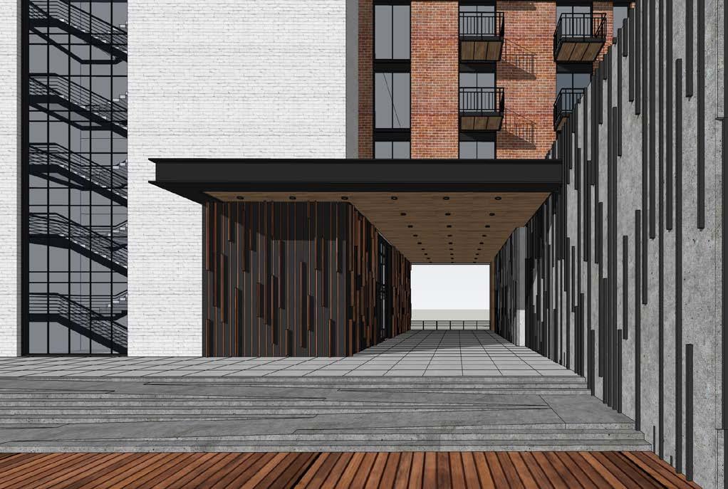
WH 5' 0" 3' 0" 3' 0" 5' 0" 12' 6" (699 SF) 12' 0" 4' 10" BED / 1 BATH 15 16 17 18 97 0 11' 1/2" 0" SF) 1 BATH LIVING ROOM 19' 6" 15' 5" 11' 2" SF) / 1 BATH 14 15 16 located in the downtown retail and parking. The site has many on the North by an street / podium level Norfolk Southern resTed Turner Dr. and
Site: Atlanta GA, US
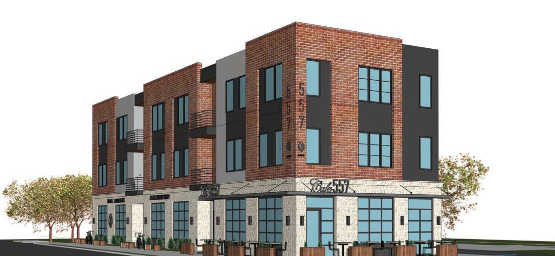
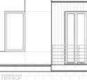
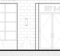
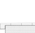
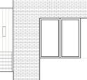
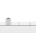
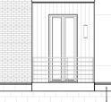
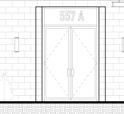
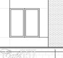
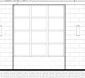
Project Description: 557 Lindsay Street is a multifamily residential project with a retail presence at the street level with two levels of apartments above.
Aug 2021 - May 2022
Role: Designer/Modeling/Layout
FORM
The form of this project was derived from the functional requirements of the building program. The challenge was to create a public street where the community would feel invited to come into the retail establishments but at the same time providing some level of privacy for the entrances to the residences above and the spaces within the apartments.
DETAIL
DETAIL
A multifamily residential project with a retail presense at the street level with two levels of apartments above. Engaged the development of massing and elevation design, and produced the digital model and design drawings for the project.
The form of this project was derived from the functional requirements of the building program. The challenge was to create a public street where the community would feel invited to come into the retail establishments but at the same time providing some level of privacy for the entrances to the residences above and the spaces within the apartments.
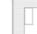
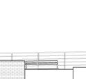
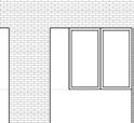
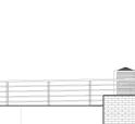
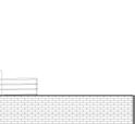
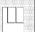
The detail ed concept of this building is derived from the need to keep costs low in order to construct affordable housing for the community. It was important for this building to fit into the context of the neighborhood. Brick and stone materials are used in the surrounding buildings. The following diagrams represents how each portion of the building façade is represented on its layer in order to create a interesting detail using various materials.
The detail ed concept of this building is derived from the need to keep costs low in order to construct affordable housing for the community. It was important for this building to fit into the context of the neighborhood. Brick and stone materials are used in the surrounding buildings. The following diagrams represents how each portion of the building façade is represented on its layer in order to create a interesting detail using various materials.
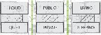


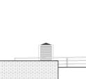
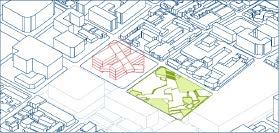
Since a public street generates more activity and noise, We placed the living dining areas on the public street side and the quieter rooms on the private side of the building.
Since a public street generates more activity and noise, We placed the living dining areas on the public street side and the quieter rooms on the private side of the building.
The idea was to create a separation between the public and private entries to the building without taking up a lot of space for circulation We used the same circulation corridor for both public and private entries coming in from opposite sides of the building. The building itself became the separation between the public and private entries.
The idea was to create a separation between the public and private entries to the building without taking up a lot of space for circulation We used the same circulation corridor for both public and private entries coming in from opposite sides of the building. The building itself became the separation between the public and private entries.


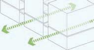


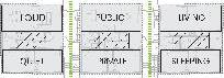
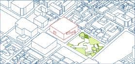
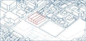
Creating a circulation corridor for both the public and private entry naturally created three divisions of the building. When looking at the plan it creates three square areas divided by 2 circulation corridors.
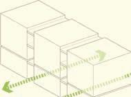
When envisioning it in three dimensions the form becomes three cubed volumes with a circulation zone in between for balconies and stairs.
Creating a circulation corridor for both the public and private entry naturally created three divisions of the building. When looking at the plan it creates three square areas divided by 2 circulation corridors.
When envisioning it in three dimensions the form becomes three cubed volumes with a circulation zone in between for balconies and stairs.
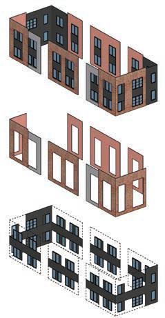
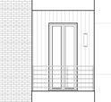
COMPLETE BRICK, FIBER PANEL AND GLASS
COMPLETE BRICK, FIBER PANEL AND GLASS
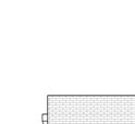
We used a technique of layering in this building to give the essence of masonry so that one would perceive this to be a brick and stone building but then peeled back those layers to reveal fiber paneling which is less costly. We started with the Stone layer at the bottom as a base. We used a thin layer of masonry to achieve the stone look at the base and emphasize the retail façade.
We used a technique of layering in this building to give the essence of masonry so that one would perceive this to be a brick and stone building but then peeled back those layers to reveal fiber paneling which is less costly. We started with the Stone layer at the bottom as a base. We used a thin layer of masonry to achieve the stone look at the base and emphasize the retail façade.
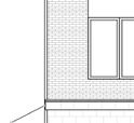
BRICK AND FIBER PANEL
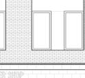
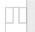
For the apartment floors we set back the brick veneer from the base and then peeled it back to reveal a fiberboard surface.
BRICK AND FIBER PANEL
For the apartment floors we set back the brick veneer from the base and then peeled it back to reveal a fiberboard surface.
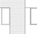
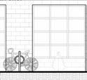
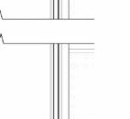
GLAZING AND BANDING
We then peeled that back to reveal a darker fiberboard banding that aligned with the glazing of the façade.
GLAZING AND BANDING
We then peeled that back to reveal a darker fiberboard banding that aligned with the glazing of PUBLIC STREET

Location: Atlanta, GA Design Architect: SHAPE | Mark Hill - Design Principal-in-Charge | Project Team: Andrew Smith, Shenjie Li, Devin Sparkman
PRIVATE DRIVEWAY
PRIVATE DRIVEWAY
FORM
Project Description: 557 Lindsay Street is a multifamily residential project with a retail presence at the street level with two levels of apartments above.
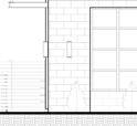
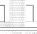
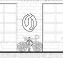
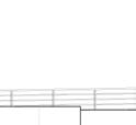
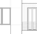
A B C D E F G H B M 3 6 0 : 5 5 7 L n d s a y S e e M x e dU s e / 2 0 2 0 0 8 0 2 0 5 5 7 L n d s a y S t C e n r a M o d e R 2 0 v t 5 3 0 2 0 2 3 6 2 7 4 9 P M PROJECT NUMBER: 202008.020 PROJECT NAME: 557 Lindsa y Street Mixed-Use Apartments SHEET NUMBER: A-102 SECOND FLOOR CONSTRUCTION PL AN Level 1 0' - 0" Level 2 13' - 0" Level 3 24' - 0" Low Roof 35' - 0" Max Roof Parapet 37' - 6" Roof Slope Peak 36' - 6" 1 2 3 4 5 6 A A B B A A A A A A B B B A A B A A AWNING, TYP STOREFRONT WINDOW, TYP D D D D D D H H STANDING BIKE RACK, TYP ALUMINUM STOREFRONT ENTRY AND WINDOWS, TYP MASONRY VENEER EXTERIOR CLADDING TYPE 1 FIBER CEMENT EXTERIOR CLADDING TYPE 2 EXTERIOR WAL SCONCE LIGHTING, TYP ALUMINUM CLAD WINDOWS AT RESIDENTIAL LEVELS, TYP FIBER CEMENT EXTERIOR CLADDING TYPE 2 STREET ADDRESS SIGNAGE, TYP MASONRY VENEER EXTERIOR CLADDING TYPE 1 BUSINESS SIGNAGE, TYP CONDENSER UNIT, TYP EMERGENCY RAILING, TYP WALL SCONCE,TYP 1 2 4 5 6 8 9 10 11 12 13 14 15 B C D G H B C D G H NOT FOR CONSTRUCTION e dU s e 2 0 2 0 0 8 0 2 0 5 5 7 L n d s a y S C e n a M o d e R 2 0 v NAME: 557 Lindsa Street Mixed-Use Apartments ELEVATION 557 Lindsay Mixed-Use NORTH 557 LINDSAY ST. 1/4" = 1'-0" A-201 1 NORTH ELEVATION WOOD FENCE BEYOND MASONRY VENEER CLADDING ISSUANCES No.Drawing Issue SAP SUBMISSION PROGRESS CD PRICING SAP UPDATED SUBMISSION PROGRESS CD PRICING
557 LINDSAY STREET
C D E D G B M 3 6 0 5 5 7 L n d a y S e M e dU s e 0 2 0 0 0 2 0 5 7 L n d s a S C e n a M o d R 2 0 v 5 3 0 0 2 3 6 0 5 7 P M PROJECT NUMBER: 202008.020 PROJECT NAME: 557 Lindsa y Street Mixed-Use Apartments SHEET NUMBER: A-700 ENLARGED STAIR PLANS & SECTI ONS 3/4" 4 GROUND


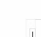

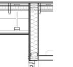

REF. REF. REF. DN UP DN UP A-200 2 -200 A-201 1 1 2 A-210 1 A-210 BALCONY 214 120 SF BEDROOM 219 114 SF BEDROOM 211 W/D W/D 1 A-212 3' 0" 3' 7" 5'4" 79 3 4 R O 78 3 8 18 20 1 8 17 20 5 8 3 13 3 8 7' 4 1/8" 28' - 10 3/8" 3' 6" 17' - 2 1/4" 5' - 3 7/8" 3' 0" 5' 9" 3 13 3 8 1 2 3 4 5 6 1 20 1 20 44 30 E Q E Q A A B B C C D D E E A A B A B A A A A A A 211 210 212 218 228 229 220A 222 220 230 238 231 221 223 219 26' 0 1/2" 1 00 " 51 P1 P1 P1 P1 P1 P1 P1 P1 P3 26' 0 1/8" 12' - 0" 1 00 " 11' 5 1/8" 2' - 0" 6' - 0" 15' 2 3/8" 4' 9 3/4" 3' - 0" 5' 8 7/8" 30 37 1 001 1 01 1 2 11' 8 7/8" 28' 0" 7' 4" 28' - 0" 7' - 4" 29' - 4" 100' 0" 8' 7" 1 00 11' - 8 7/8" 2' 0" 213 ALIGN ALIGN 233 232 8' - 7" 1' 3 3/4" 4' 1 1/2" 51 90 237 30 30 W/D 12' 7 3/8" 2' 9" 12' 0" 210A 217 CL 1 16 44 30 30 48 1 2 1 21 0 E Q E Q 14 37 1' - 4 1/2" 3' - 2 1/8" 215A 227 236A ENTRY 210 SITTING AREA 216 BALCONY 224 225A SITTING AREA 236 3' - 3" 3' 3" 3' - 3" B A 2 24 81 1 3 8 3' - 7 1/8" 6'-2'' RO. 6' 1" 4' 0" 3' - 11" 6'-2'' RO. 6' 1" 4' 0" 4' 0" 6'-2'' RO. 6' 1" 7' - 10" 6'-2'' RO. 6' - 1" 4' 0" 4' - 0" 6'-2'' RO. 6' 1" 3' 11" 4' - 0" 6'-2'' RO. 6' 1" 4' 9 3/8" 14' 0" 14' 0" STAIR 1 STAIR 2 57 1 4 79 3 4 R O 78 3 4 20 " 20 31 R O 30 3'-1'' RO. 3' - 0" 3'-1'' RO. 3' - 0" 4' - 0" 8' - 0" 4' - 0" 8' - 0" 4' - 0" 3'-1'' RO. 3' 0" 3'-1'' RO. 3' 0" 3'-1'' RO. 3' 0" 4' 0" 8' 0" 4' 0" 8' 0" 4' 0" 3'-1'' RO. 3' 0" 3'-1'' RO. 3' 0" 3'-1'' RO. 3' 0" 4' 0" 8' 0" 5' 4" 8' - 0" 4' - 0" 20 31 R O 30 1 24 31 31 R O 30 ENTRY 220 16' 0" 17' - 4" 219A 229A 211A 221A 231A 238A TV OPT A A C APT. UNIT 1 APT. UNIT 2 APT. UNIT 3 ENTRY 2300 30 50 500 50 6' 2" RO. 6' 1" HALL 226 CL PNL JT 04 5 8 CL PNL JT B B B B B STORAGE 215A KITCHEN 213 LIVING / DINING ROOM 215 CL 210A MECH 217 LAUNDRY 218 CL 211A CL 219A LINE OF SOFFIT ABOVE BATHROOM 212 KITCHEN 223 LIVING DINING ROOM 225 STORAGE 225A MECH 227 LAUNDRY 228 117 SF BEDROOM 229 117 SF BEDROOM 221 CL 229A CL 221A CL 220A 114 SF BEDROOM 231 122 SF BEDROOM 238 KITCHEN 235 LIVING DINING ROOM 234 BATHROOM 237 CL 236A CL 238A CL 231A LAUNDRY 232 MECH 233 BATHROOM 222 LINE OF SOFFIT ABOVE LINE OF SOFFIT ABOVE 1 A-213 P2 P2 P1 P2 P2 P1 P1 P1 P2 P2 P2 P1 P1 P3 2' 0 7/8" 8' 7" 2' - 0 3/4" 4' 0 3/4" 5' - 3 5/8" P1 2' 1" 3' 6" 14' - 8 1/4" 3' - 2 1/8" 6' 0" 27' 4 3/8" 42 16 21 P04 P06 AWNING BELOW AWNING BELOW WALL OR DOOR MOUNTED CARD READER CR 1. CONTRACTOR ALL DISCREPANCIES AND EXISTING WORK OR INSTALLATION 2. ALL DIMENSIONS BOARD, COLUMN CONCRETE, 3. TYPICAL INTERIOR WALL DIMENSION NOTED. 4. ALL PARTITIONS 5. REFER TO 6. PROVIDE WALL WALL MOUNTED 7. REFER TO PLUMBING LOCATIONS 8. ALL BASE CABINETS WOOD FILLER 9. PROVIDE GLASSMAT ROOM TILE FLOOR PLAN 1 2 C D E F G H Drawn By Approved By NOT FOR 557 Lindsay Mixed-Use SECOND CONSTRUCTION Approver 557 LINDSAY A-102 ENTRY ENTRY No.Drawing PROGRESS CD PROGRESS CD Level 3 Roof Slope Peak D E A-440 5 9 R 1 0 R 7 R 1 6 R 2 3 R S E R S 1 30 1 9 R S E R S 10 Level 1 0' - 0" Low Roof 35' - 0" Max Roof Parapet 37' - 6" Roof Slope Peak 36' - 6" D A-440 5 A-702 2 7 8 10 11 12 13 14 7 8 10 11 12 13 14 Drawn By Approved By 557 Lindsay Street Mixed-Use Apartments ENLARGED STAIR SECTION & Approver 1/2" = 1'-0" A-701 2 4 -c No.Drawing Issue DescriptionDate Level 1 0' - 0" Level 2 13' - 0" Level 3 24' - 0" Low Roof 35' - 0" Max Roof Parapet 37' - 6" Roof Slope Peak 36' - 6" A B CONCRETE FOUNDATION CONCRETE SLAB ON FOUNDATION STOREFRONT SYSTEM (ENTRY) STOREFRONT SYSTEM (TRANSOM) WOOD JOIST STRUCTURAL FRAMING TYP. BALCONY RAILING TYP. BALCONY FRENCH DOOR ROCK FACE CMU BLOCK BALCONY RAILING BALCONY FASCIA 0' - 5 1/8" WOOD JOIST STRUCTURAL FRAMING TYP. TOP PLATE. HEADER BEAM 116 1 11 10 1 30 01 0 1 2 19 1 8 16 3 8 30 3 4 97 1 8 95 5 8 30 3 4 EDGE BEAM (SEE STRUCTURAL 2X4 BRACE 5/16'' WOOD PANNEL 1/2'' GYP BOAED 5/8'' PLYWOOD TOP PLATE TYP 1 2 3 4 5 6 B C D F G H K B I M 3 6 0 5 5 7 L n d s a y S r e e M x e dU s e / 2 0 2 0 0 8 0 2 0 5 5 7 L n d s a y S C e n a M o d e R 2 0 r v 5 3 0 / 2 0 2 3 6 3 0 : 1 5 P M PROJECT NUMBER: 202008.020 PROJECT NAME: 557 Lindsa y Street Mixed-Use Apartments SHEET NUMBER: A-400 EXTERIOR WALL SECTIONS 3/4" = 1'-0" A-400 3 Section 3 -Callout 2 REF. DN UP REF. UP DN D E - 1 3 2 8T @ 11''4'' 9T @ 11'' = 8'3'' 3' 6 9/16" 0' 3" 3' 6 9/16"118 3 1 20 1 0' 0 9/16" 7' 3" 0' 0 9/16" 2' 8 5/8" 2' 1 3/8" 2' 8 5/8" 0' 0 9/16" 7' 3" 0' 0 9/16" 7' 4 1/8" 115T @ 11'' 13'9'' LINE OF SOFFIT ABOVE WALL SCONCE, TYP BELOW 2 3 B D3 2 0' 3" 59 1 8 88 1 81 5 8 1829T @ 11'' = 8'3'' 6T @ 11'' = 5'6'' 2' 10 1/2" 0' 10 1/2" 2' 10 1/2" 0' 0 9/16" 7' 3" 0' 0 9/16" 7' 1/8" 8T @ 11'' =4'' 3 5 8 10 11 12 13 14 15 3 8 10 11 12 13 14 15 D G Drawn By Approved By Project No. Drawing No. NOT FOR CONSTRUCTION 12/23/2021 202008.020 A-700 557 Lindsay Street Mixed-Use Apartments ENLARGED STAIR PLANS & SECTIONS Approver Author 557 LINDSAY ST. NW, ATLANTA GA 30314 3/4" = 1'-0" A-700 1 Level 3 -Callout 8 = 1'-0" GROUND FLOOR PLAN -Callout 1 3/4" = 1'-0" A-700 2 Level 3 -Callout 9 ISSUANCES No.Drawing Issue DescriptionDate PROGRESS CD PRICING SET 05/30/2023
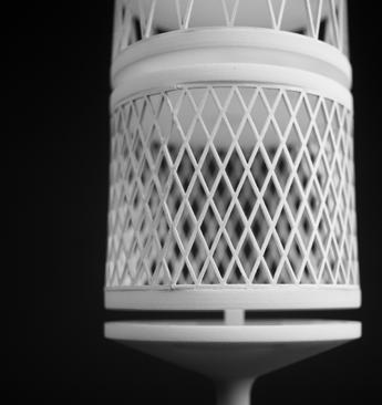
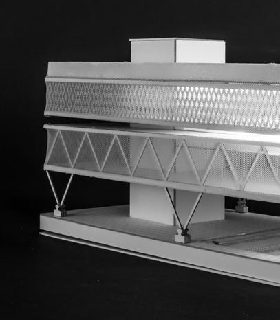
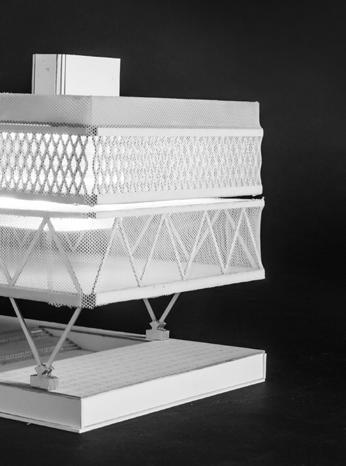
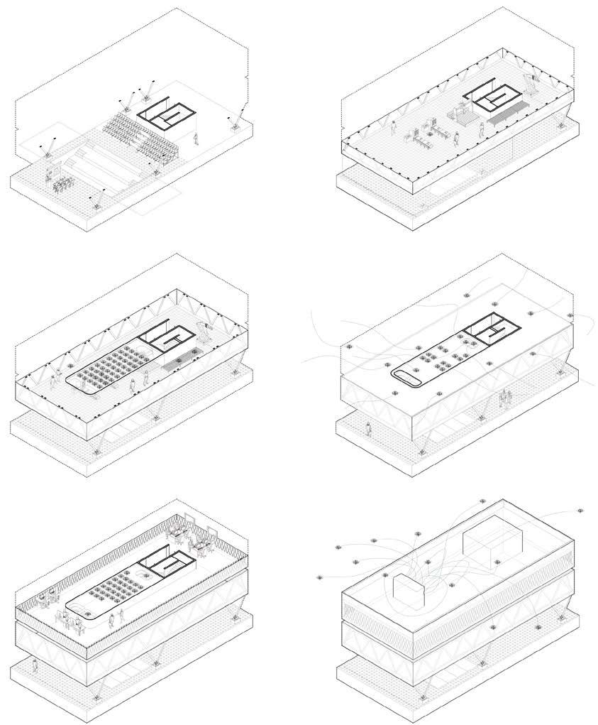
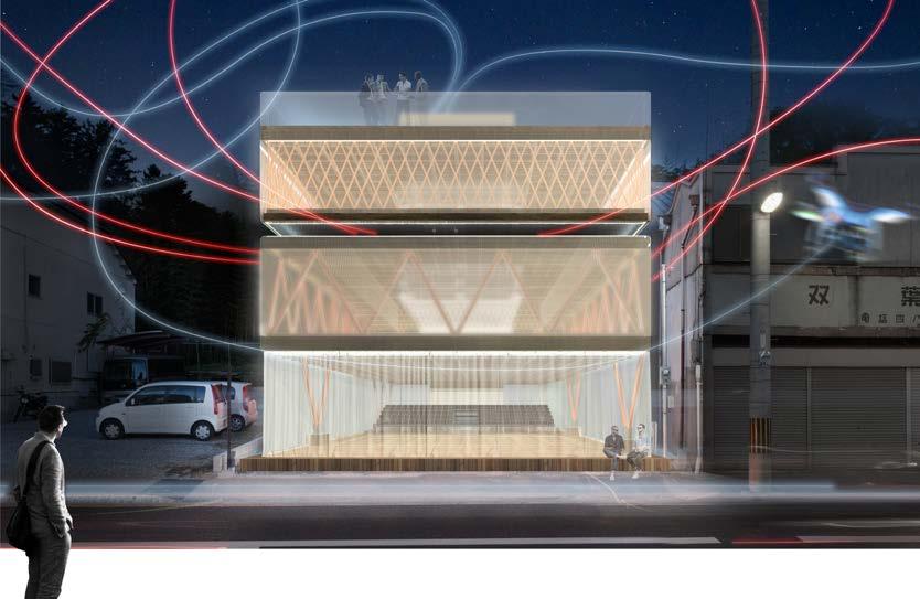
DRONE PARKING DECK
Aug 2018 - Dec 2018
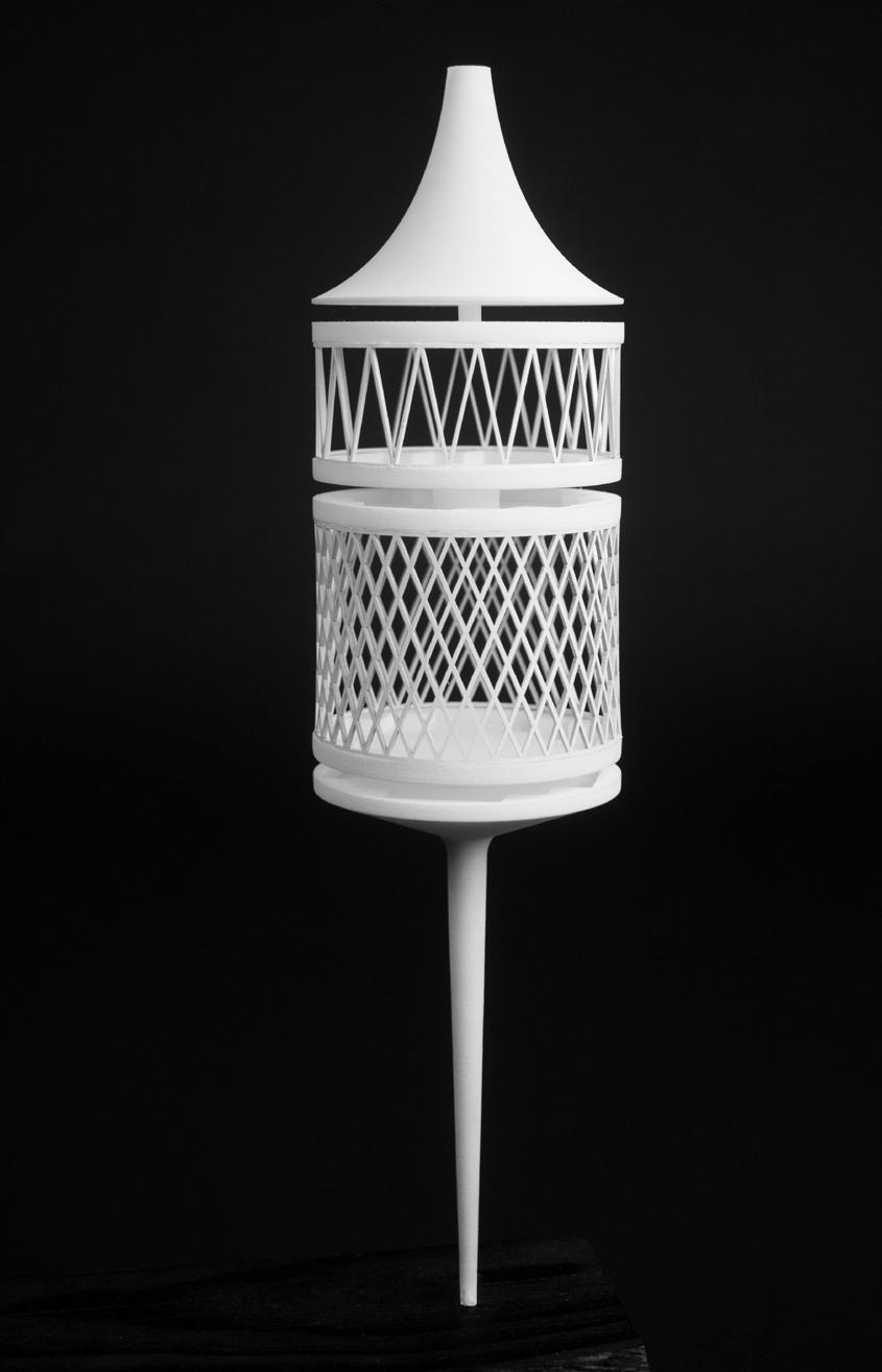
The drone parking space is inspired by the concept of a pancake, where each layer is exclusively for drones within a 500 cubic meter volume. This design is meant to fill gaps between urban buildings and reach inaccessible heights. I achieved this by creating a cylindrical space and slicing it into pancake-like drone parking levels, each with a distinct surface pattern reflecting the drone’s function.


Academic work Georgia Institute of Technology Personal work


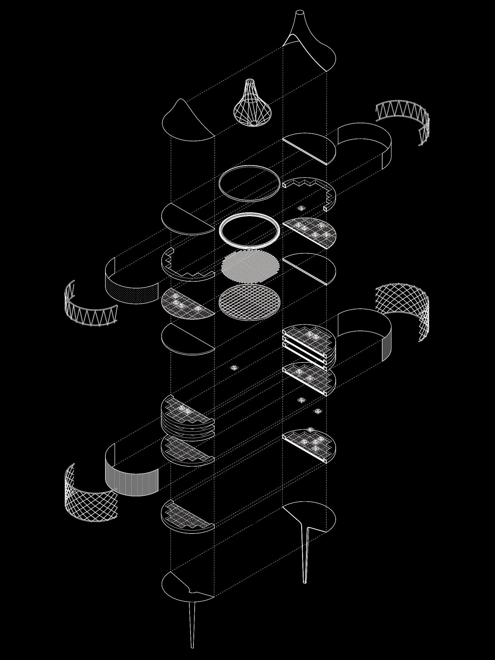
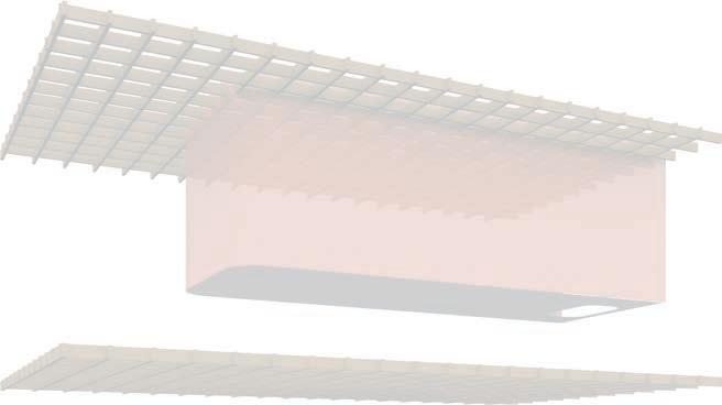

Then applied these principles to design a building that houses both a drone parking space and a Fab Lab. Following the same design type as the pancake concept, I scaled one layer of the parking space to serve as a Fab Lab and developed additional layers for various purposes, including flexible and gathering spaces on the ground level and roop top garden/ dog park on for the roof.
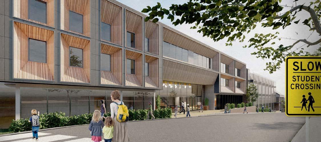
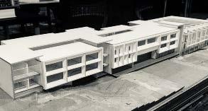
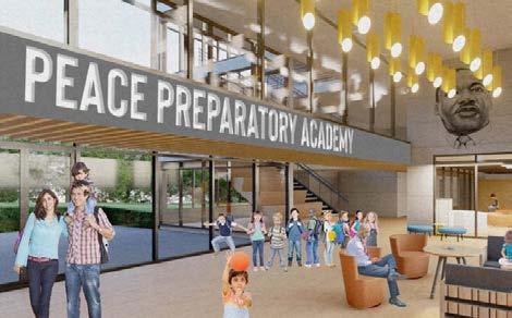
PECE PREP ACADEMY CAMPUS
Site: Atlanta GA, US
Aug 2019 - April 2020
Role: Designer/Digital&physical Modeling/Layout
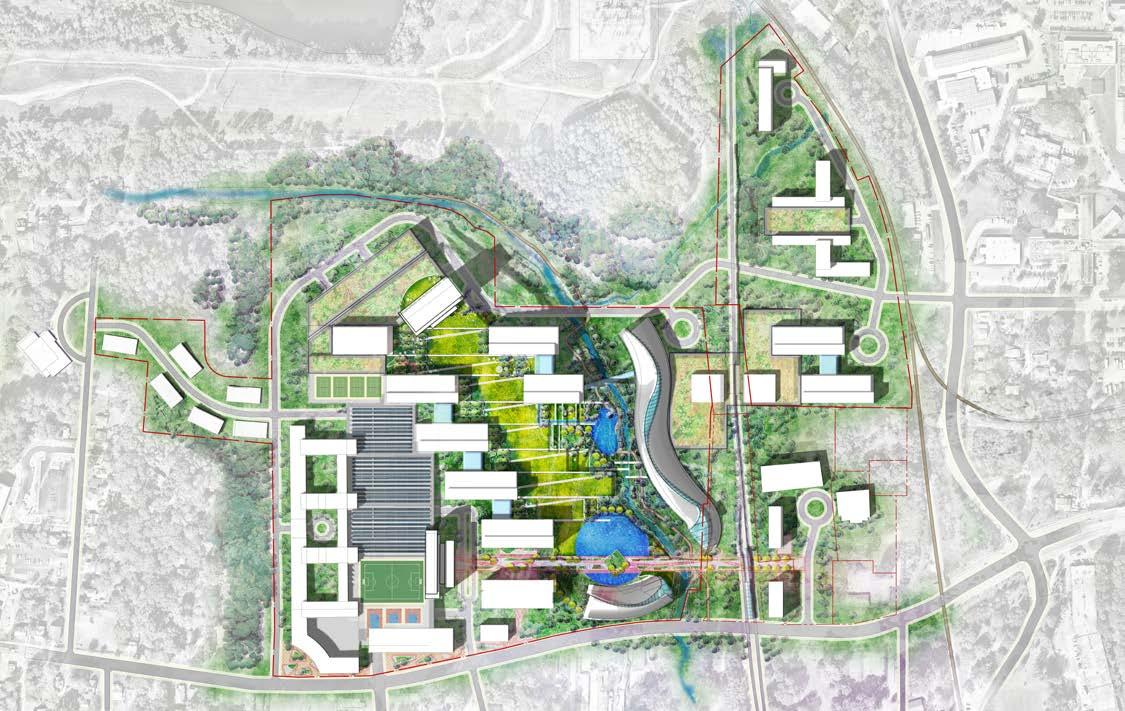
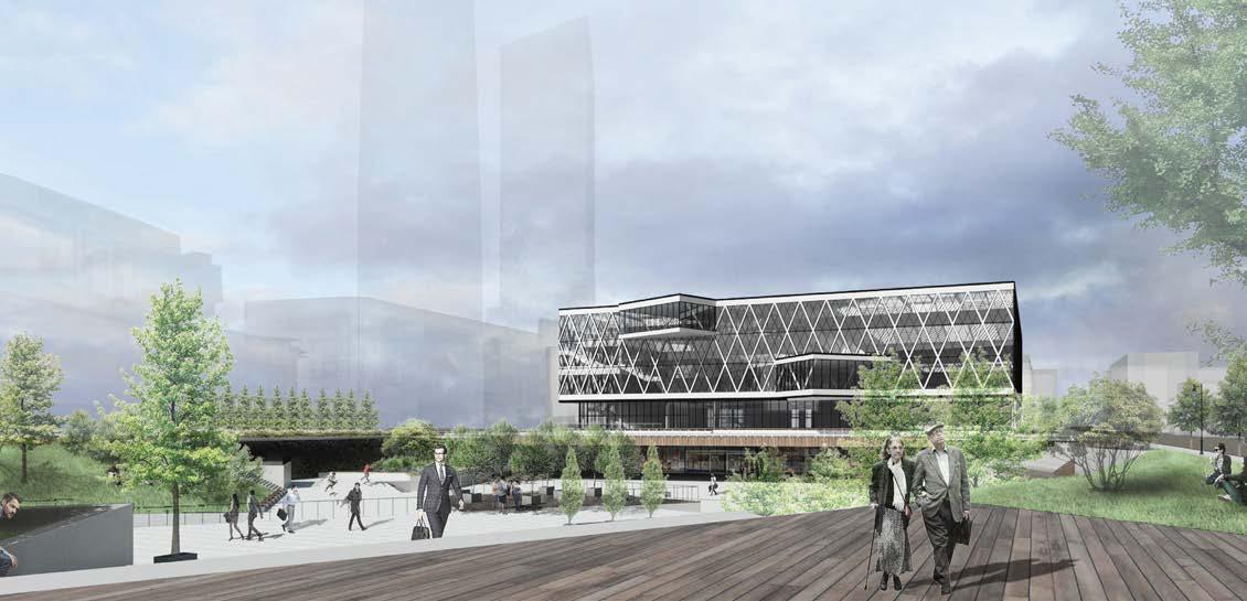
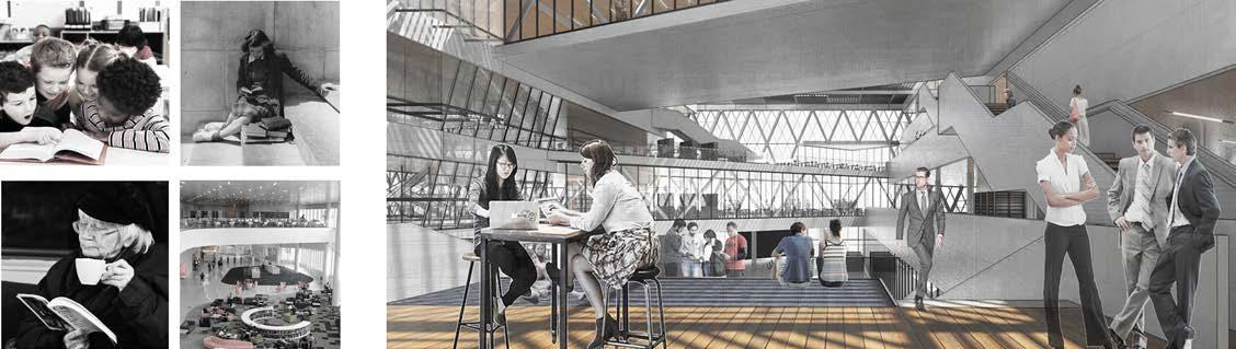
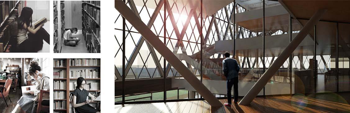
Peace Preparatory Academy is a 15,000 SF design study for a school in the English Avenue area. This 4 story K-12 academy divided the class levels per floor. The project offers a Gymnasium, Library, and Labs. The team worked with the leadership of PPA in creating a conceptual design for a private school of approximately 150 students. Part of the design solution was to create a center in the community that was very viable, fun, culturally rich, and centered on learning and education.


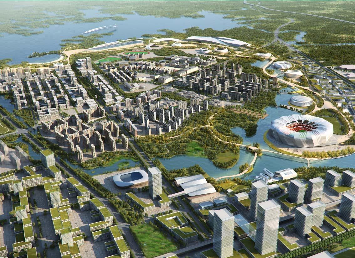
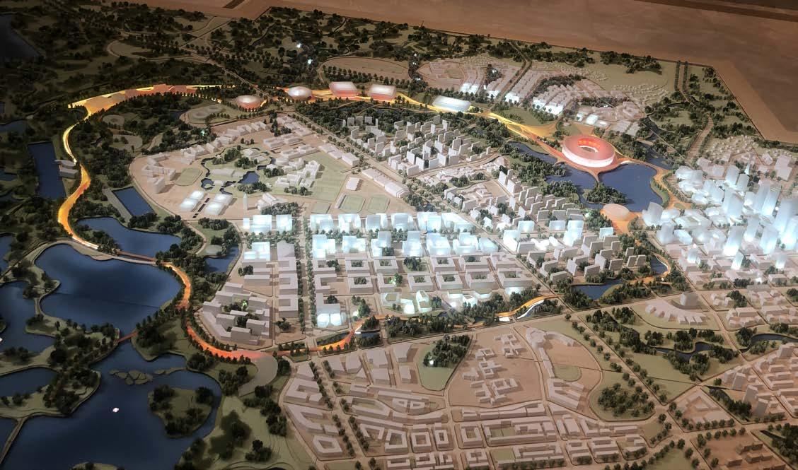
Concept design for a community tech pampus and residential & comercial misxed use community in west of midtown Atlanta. Team with HOK produced the diagrams, master plan design and massing model study.


lt en MARIETTAB N O R T H DE DRIVE HOWELLMILLRD FRANICISST 10 minutes drive MIDTOWN GEORGIA TECH ATLANTIC YARDS QUARRY YARDS WESTSIDE RESERVOIR PARK GROVE PARK NEIGHBORHOOD SITE ENGLISH AVENUE KNIGHT PARK NEIGHBORHOOD towards ATLANTA UNIVERSITY CENTER INNMAN YARDS beltline BANKHEAD marta 14TH STREET SPRING STREET 17TH STREET 10TH STREET kudzu trail I-85 I-75 Centennial Academy Charter School Tech Square CLOVER IN ATLANTA INTEGRATING CLOVER WITH THE ATLANTAN URBAN FABRIC DONALD LEE HOLLOWELL PKWY PROCTOR CREEK JEFFERSON STREET proctor creek trail FOUR CORNERS Grove Park Theater Grove Park Rec Center “MAIN ST” MOZLEY PROCTTORCRREREEK TORRC TOR TRAIL SILVER COMMET/PROCTOR DONALD LEE HOLLOWELL PKWY NW NORTHSIDE DR NW NORTHSIDEDRNW RALPH DAVID ABERNATHY FWY IVAN ALLEN BLVD NW JOSEPH E. BOONE BLVD NW WEST MARIETTA ST NW JOSEPH E. BOONE BLVD NW JOHNSON RD NW MARIETTABLVDNW JEFFERSON ST NW JOHNSON RD NW 10TH ST NW MARTA TO AIRPORT TO DOWNTOWN TO CHATT.RIVER TO GEORGIA TECH TO A.U.C. M.L.K JR DR NW CHAPPELL RD GEORGIA INSTITUE OF TECHNOLOGY MOREHOUSE SPELMAN UNIVERSITY CENTENNIAL ACADEMY CHARTER SCHOOL 10 MIN 35 MIN DRIVE Secondary Street MARTA Stops MARTA Lines INTEGRAL HKS SHAPE CONNECTIVITY MAJOR CORRIDORS The site is well connected to important destinations through prominent corridors in all directions STIFF WESTSIDE RESERVOIR PARK bellwood quarry (HIGHEST POINT) (PARK VIEW) (MIDTOWN VIEW) Quarry Hills SITE Bankhead MARTA Fulton County M R TTA BLVD B LTLNETRAIL P OC ORC EEK PROJECT CLOVER UNDERSTANDING SITE AND SURROUNDINGS KNIGHT PARK NEIGHBORHOOD GROVE PARK NEIGHBORHOOD FUTURE MIX-USE NEIGHBORHOOD CHAPELLSTREET EL IDG STREET 20 acres 10 acres Quarry Yards 70 acres KUDZU TRAIL PROC DONALD LEE HOLLOWELL PARKWAY ProjectClover Understanding Site and Surroundings
CLOVER PARK Site: Atlanta GA, US Feb 2021 - May 2021 Role: Site&Mapping analysis Drafter/Master plan desig team
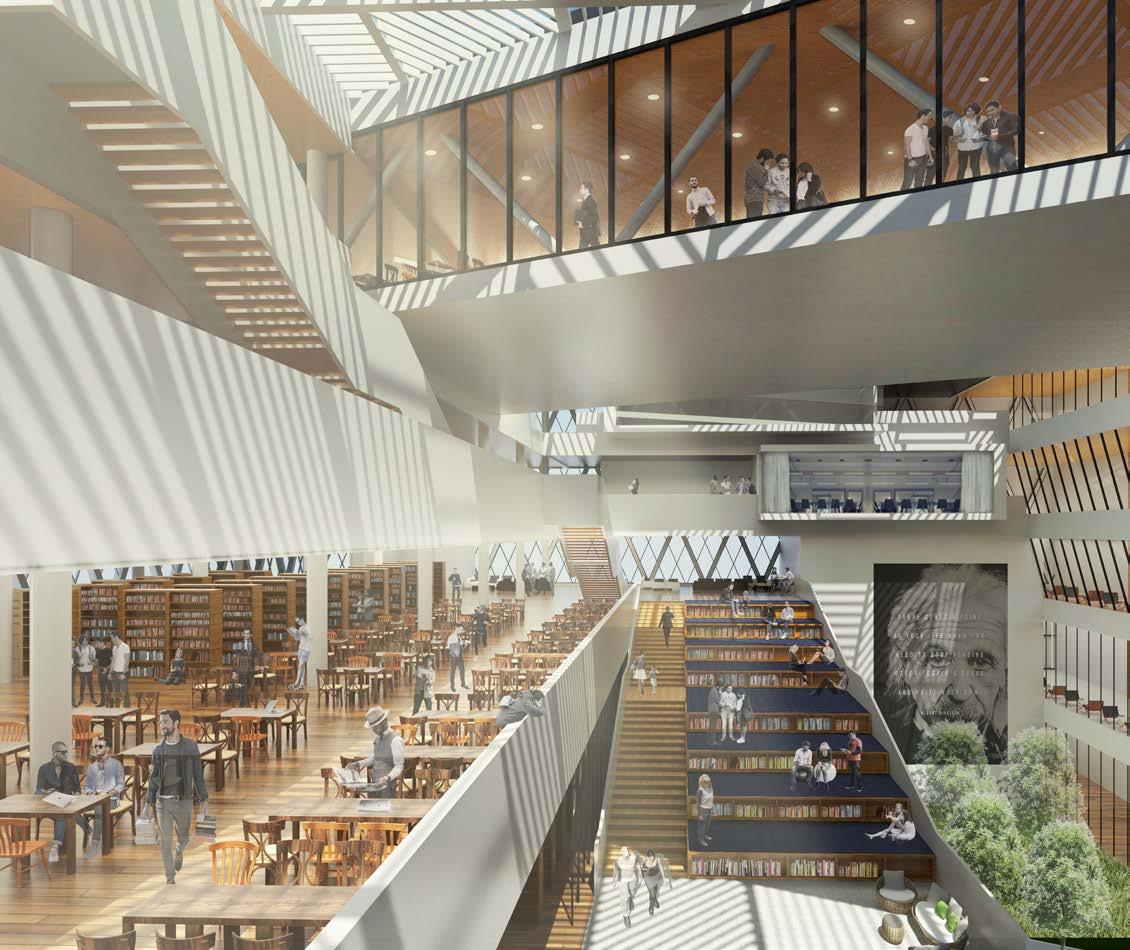
TIANJIN CITY LIBRARY
Site: Tianjin, China 2016
Academic Personal work
Design of urban library
Site: Binjiang Street Tianjin, China
Apr 2016 - July 2016
In this area, the environment are quiet enough but people can do some low voice discussion, also this area including children reading space and aged people reading
Academic work in Tianjin Chengjian University Group work for urban design Personal work for Library design Outside
This kind of area in library can provide readers a quiet environment to do their reading
seating/reading space, and such things happen frequently in our life.
space without distractions.
aged
reading space.
‘Focus’
Low voice discussion, children reading and
people

1.According to the city texture, the cubic can fit the site and the scale of this area.
6. Add the architectural skin, enclose the internal space.
2. Divide the cubic in order to enrich the space and become more opening.
5.Two different connections have a relationship with the new city landmark and urban park; old landmark and old urban area.
3. Central space absorbing the sunlight, the northen side faced the public park and let more sunlight get into the public park.
4.Layout the floors according to the code.
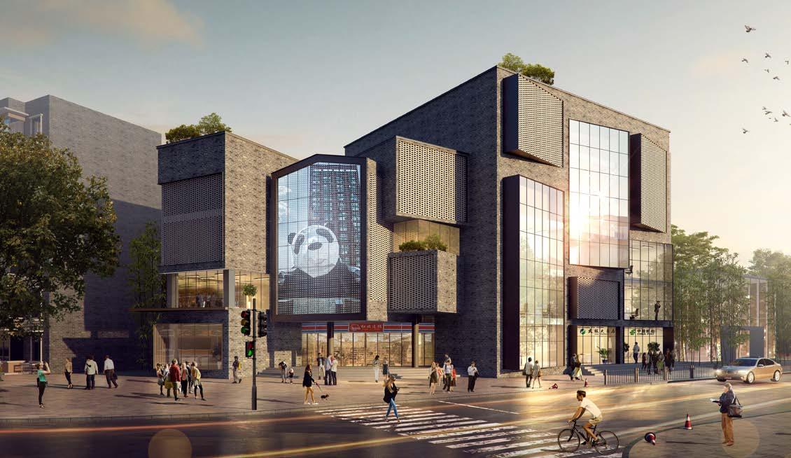
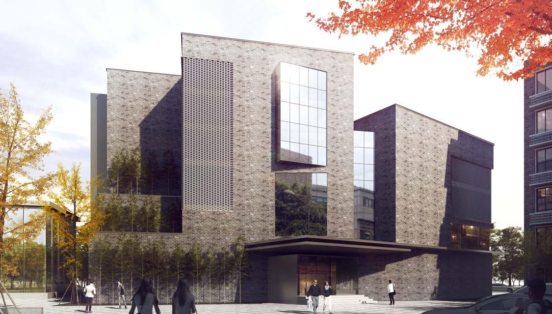
RENOVATION KUIXINGLOU #1
Site: Chengdu, Sichuan, China
July 2018 - Aug 2018
Team Work, Personal Design
A office building renovation program in Chengdu, the government wants to transform it into a culture center since the streets and the community around this building was influenced by the culture of Chengdu for many decades.
This street still has a strong local life vitality, restaurants, tea houses, and community, all these elements combine together as a cultural area.
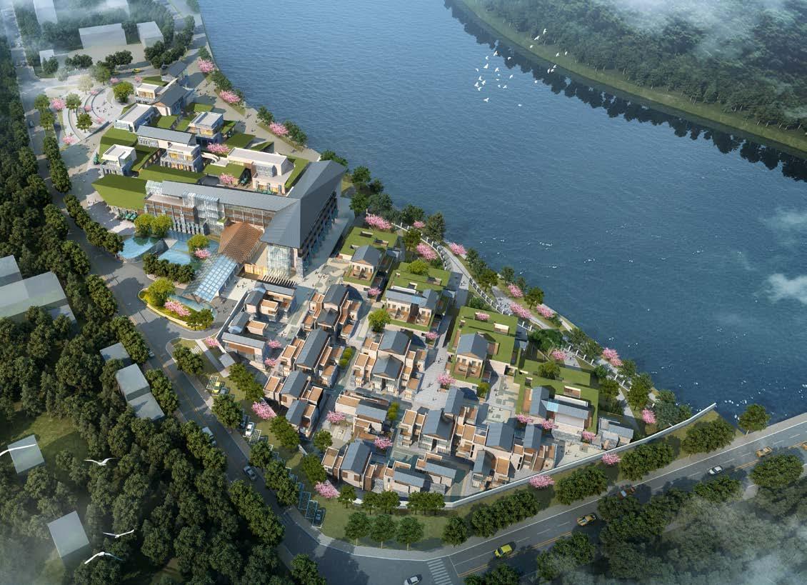
 LINZHI HOTEL Site: Linzhi, Tibet, China Aug 2018 Team work
CHENGDU OLYMPIC PARK
Site: Chengdu Sichuan China
Aug 2018
Team work