
Isuzu Npr Nqr 2001 Electrical Troubeshooting-15i16489 Full download: http://manualplace.com/download/isuzu-npr-nqr-2001-electrical-troubeshooting-15i16489/ This is the cut pages sample. Download all 260 page(s) at: ManualPlace.com

CircuitIndex Diesel Gas ... 2

Airconditioner 2-10 Blowercontrols .............. 60 ....... 60-1 ... 6
Compressorcontrols..........63 ....... 63-2
Anti-lockbrakesystem(ABS).....44 ....... 44-4 201
A/Tshiftindicator .............. 89 ....... 89-1 202 Automatictransmissioncontrols ... 39 ....... 39-4 .203 Backuplights ............... 112 ...... 112-1
Blowercontrols ................ 60 ....... 60-1
Brakelights................110-12.....110-13 Brakewarningsystem. .......... 71.......71-2
Ceramicheater................ 61
Chargingsystem...............22 ....... 22-2
Cigarettelighter. .............. 155 ....... 155
Compressorcontrols............63 ....... 63-2 Consolelights ................ 117......117-2
Corneringlights.............110-16 ..... 110-18 Dashlights .................. 117 ..... .117-2
Domelight................... 114 ....... 114
Enginecontrols................23 ........ 24 81-2
Enginecoolanttemperaturegauge .. 81 Enginestopsystem. ............ 26
Exhaustbrakesystem. .......... 25

Thismanualcontainsthefollowingtroubleshooting information:
• FuseInformation
• CircuitDetails
ElectricalCircuitSchematic
ComponentLocationIndex
CircuitOperation QuickChecks(ifrequired)
Troubleshooting(ifrequired)
• ComponentLocationPhotographs
• HarnessConnectorFaces
HarnessRoutingViews
TheElectricalCircuitSchematicshouldalwaysbe yourstartingpointinusingthisElectricalTroubleshoot¬ ingManual.Theschematicshowstheelectricalcurrent pathswhena circuitisoperatingproperly.Itisessential tounderstandhowa circuits/iou/dworkbeforetryingto figureoutwhyitdoesn't.Schematicsareshownwith thestarterswitch intheOFFpositionandother switchesintheoffor"atrest"position.
TheComponentLocationIndexhelpsyoufindwhere thepartsofa circuitarelocatedin a vehicle.Abrief statementofthelocationisgivenandalsoa reference to a photographthatshowsthecomponent.These ComponentLocationPhotographsareinsection201. Theindexalsoliststhenumberofcavitieswithineach connectorandtheconnectorcolor.Notallcavitieswill havewires.
TheCircuitOperationwillhelpyoutounderstandthe circuit.Itdescribesthecomponentsandhowthecircuit works.
Thismanualisorganizedintosectionswithmostsec¬ tionscontainingcircuitdetails.Eachsectionhas a uniquenumberthatwillnormallyremainthesame, yearafteryear.Forexample,theheadlightscircuitwill besection100withthefirstpageofthesectionnum¬ bered100.Thefollowingpagesofthissectionwillbe numbered100-1,100-2,and100-3.

Wavylinemeansthewireis -^ brokenbythebindingofthebook butcontinuesonthenextpage
Arrowmeanswireconnectsto anothercircuit;showsdirection ofcurrentflow Motor Brush
Circuitiscontinuedwhereindicated; arrowshowsdirectionofcurrentflow andisrepeatedwherecircuitcontinues
Diode;positive currentflowsin arrowdirection


Circuitschematicsbreaktheentireelectricalsystem intoindividualcircuits.Electricalcomponentsthat worktogetherareshowntogether.
Eachdrawingisarrangedsothatcurrentflows frompositiveatthetopofthepage,toground,at thebottomofthepage.The"hot"labelsatthetopof a fuseshowwhenthestarterswitchsuppliespowerto thatfuse.
Wiresthatconnecttoanothercircuitareshownwithan arrowheadpointinginthedirectionofcurrentflow.The nameofthecircuitthatshareswiringisprovidedforref¬ erence.
"SeeFuseBoxDetails"meansthatthereareothercon¬ nectionstocircuitsthatarenotshown.Theseshared circuitsareshownontheFuseBoxDetailscircuitsche¬ matic."SeeGroundDistribution"meansthatthereare sharedgroundcircuitswhichareshownontheGround Distributioncircuitschematic.
Noattemptismadeontheschematictorepresent componentsandwiringastheyphysicallyappearon thecar.Forexample, a 4-footlengthofwireisnot treatedanydifferentlyina schematicthanonewhichis onlyafewincheslong.Thenumberofcavitiesforeach connectorislistedintheComponentLocationIndex ratherthanbeingillustrated.Similarly,switchesand othercomponentsareshownassimplyaspossible withregardtofunctiononly.
Theexampleonthispageshowsa hornsschematic. LocatethehornschematicbyusingtheCircuitIndex. Thecircuitschematicwilllooksimilartotheoneshown below.Theschematicisreadfromtoptobottom.
Voltageisappliedtothehornrelayatalltimes.When therelaycoilisgroundedbyclosingthehornswitch, therelaycontactsclose.Whentherelaycontactsare closed,boththeLHandRHhornsareenergized.
ThePowerDistributionschematicshowsthewiring fromthebatteryandgeneratortothestartersolenoid, relaybox,fusebox,starterswitchandlightswitch.The firstcomponentaftera fusiblelinkisalsoshown.Incer¬ taininstances,thefirstcomponentafterafuseboxfuse andlightswitchisalsoshown.
ThePowerDistributionschematicreferstoFuseBox DetailsandLightingSwitchDetailsschematics.By usingthesethree(3)schematics,powerdistribution wiringcanbefollowedfromthebatteryandgenerator tothefirstcomponentaftera fusiblelink,fuse,andlight switch.Theabilitytofollowthepowerdistributionwiring tothefirstcomponentineachcircuitisextremelyhelp¬ fulinlocatingshortcircuitswhichcausefusiblelinks andfusestoopen.
Thefusesintheschematicbeloware"HotAtAll Times,"sincebatteryvoltageisalwaysappliedtothem.


TheFuseBoxDetailsschematicshowsallofthewiring betweena fuseandthecomponentsconnectedtothat fuse.TheFuseBoxDetailsschematicishelpfulin locatinga shortcircuitthatcausesa fusetoopen.This schematicmayaidintroubleshootinganinoperative circuitbyshowinga secondcircuitthatusesthesame fuse.Ifthesecondcircuitworks,thenthefuseandcer¬ tainwiresoftheinoperativecircuitaregood.


TheGroundDistributionschematicsshowwhichcom¬ ponentsshare a groundpoint.Thisinformationcan oftenbea time-saverwhentroubleshootinggroundcir¬ cuits.Forexample,intheschematicbelow,ifboth headlightsandthepark/turnlightononesideareall out,youcouldsuspectanopenintheircommon groundwireorthegroundconnectionitself.Onthe otherhand,ifoneofthelightsworks,youknowthatthe groundandthewireuptothesplicearegood.You havelearnedthisjustbyinspectingtheschematicand knowingthevehicle'ssymptoms.Noactualworkonthe lightingsystemisneeded.
Acomponentlocationindexfollowseachschematic. Exceptforthelocationofobviouscomponentslikeleft headlight,theindexliststhelocationofeverycompo¬ nent,connectorandgroundintheschematic.The indexalsogivesreferencestocomponentlocationpho¬ tographslocatedinsection201.Thenumberofcavities ineachconnectorandtheconnectorcolorisalso listed.Wiresmaynotbeusedinallconnectorcavities.

Thefollowingfive-steptroubleshootingprocedureis recommended:
Checktheproblemcircuit'soperationtobesureyou understandwhat'swrong.Donotbegindisassemblyor testinguntilyouhavenarroweddownthepossible causes.
Ifthesystemyouaretroubleshootinghasa built-inselfdiagnosticsystem,refertotheappropriatesectionof theServiceManual.
Analyzetheschematic.ReadtheCircuitOperationtext ifyoudonotunderstandhowthecircuitshouldwork. Checkcircuitsthatsharethewiringwiththeproblem circuit.Thenamesofcircuitsthatsharethesamefuse, ground,switch,etc.,areincludedoneachelectrical schematic.SharedcircuitsarealsoshownonPower Distribution,GroundDistribution,DashFuseBox,and LightingSwitchDetailspages.Trytooperatethe sharedcircuits.Ifthesecircuitswork,thentheshared wiringisOK.Thecausemustbewithinthewiringused onlybytheproblemcircuit.Ifseveralcircuitsfailatthe sametime,chancesarethepower(fuse)orgroundcir¬ cuitisfaulty.
• narrowdownthepossiblecauses
• usethetroubleshootinghints
• makethenecessarymeasurementsasgivenin thetroubleshootingprocedures
• beforeyoureplacea component,checkpower, signal,andgroundwiresatthecomponenthar¬ nessconnector
Oncethespecificproblemisidentified,maketherepair. Besuretousepropertoolsandalwaysobservesafe procedures.
Checktherepairedcircuit'soperationinallmodesto makesurethatyou'vefixedtheentireproblem.Ifthe problemwasa blownfuse,testallcircuitsonthatfuse. Makesurethatnonewproblemsturnup.
Usea voltmeterortestlighttocheckforvoltage.While a testlightshowswhetherornotvoltageispresent, a voltmeterindicateshowmuchvoltagethereis.
CAUTION:Anumberofcircuitsincludesolidstate devices.Voltagesinthesecircuitsshouldbetested onlywith a 10-megaohmorhigherimpedance digitalmultimeter.Neverusea testlightoncircuits thatcontainsolid-statedevices.Damagetothe devicemayresult.
Oncircuitswithoutsolid-statedevices, a testlightmay beusedtocheckforvoltage.Atestlightismadeupof a 12-voltbulbwith a pairofleadsattached.After groundingonelead,touchtheotherleadtovarious pointsalongthecircuitwherevoltageshouldbe present.Thebulbwillgoonifthevoltageatthepoint beingtestedisgreaterthan5volts.
Usea self-poweredtestlightorohmmetertocheckfor continuity.Theohmmetershowshowmuchresistance thereisbetweentwopointsalonga circuit.Lowresis¬ tancemeansgoodcontinuity,
CAUTION:Neverusea self-poweredtestlighton circuitsthatcontainsolid-statedevices.Damageto thesedevicesmayresult.
Diodesandsolid-statedevicesina circuitcanmakean ohmmetergivea falsereading.Tofindoutifa compo¬ nentisaffectinga measurement,takeonereading, reversetheleads,andtake a secondreading.Ifthe readingsdiffer,thecomponentisaffectingthemea¬ surement.
Circuitsthatcontainsolid-statedevicesshouldonlybe testedwitha 10-megaohmorhigherimpedancedigital multimeter.
Aself-poweredtestlightconsistsofa lightbulb,battery andtwoleads.Iftheleadsaretouchedtogether,the bulbwillgoon.
Aself-poweredtestlightisonlyusedonanun-powered circuit.Firstdisconnectthebatteryorremovethefuse thatfeedsthecircuityouareworkingon.Selecttwo pointsalongthecircuitthroughwhichthereshould havecontinuity.Connectoneleadoftheself-powered testlighttoeachpoint.Ifthereiscontinuity,thetest light'scircuitwillbecompletedandthebulbwillgoon.
Usea jumperwiretobypassanopencircuit.Ajumper wireismadeupofanin-linefuseholderconnectedtoa setoftestleads.Itshouldhavea fiveamperefuse. Neverusea jumperwireacrossanyload.Thisdirect batteryshortwillblowthefuse.
Thistestmeasuresvoltageina circuit.Whentestingfor voltageata connector,youmaynothavetoseparate thetwohalvesoftheconnector.Instead,probethe connectorfromtheback.Alwayscheckbothsidesof theconnectorbecausedirtandcorrosionbetweenits contactsurfacescancauseelectricalproblems.
1. Connect one lead of test light to known good ground,orifyouareusinga voltmeter,besureyou connectitsnegativeleadtoground.

2. Connecttheotherleadofthetestlightorvoltmeter tothepointyouwanttocheck.
3. Ifthetestlightglows,thereisvoltagepresent.Ifyou areusinga voltmeter,notethevoltagereading.It shouldbewithinonevoltofmeasuredbatteryvolt¬ age.Alossofmorethanonevoltindicatesaproblem.
Shortfindersareavailabletolocateshortstoground. Theshortfindercreatesa pulsingmagneticfieldinthe shortedcircuitandshowsyouthelocationoftheshort throughbodytrimorsheetmetal.Itsuseisexplainedin thefollowingtroubleshootingtests.
Thistestchecksforcontinuitywithina circuit.Whentest¬ ingforcontinuityata connector,youmaynothaveto separatethetwohalvesoftheconnector.Instead,probe theconnectorfromtheback.Alwayscheckbothsidesof theconnectorbecausedirtandcorrosionbetweencon¬ tactsurfacescancauseelectricalproblems.
1. Disconnectthenegativecablefromthecarbattery.
2. If you are using an ohmmeter, hold the leads togetherandadjusttheohmmetertoreadzero ohms.
3. Connectoneleadofself-poweredtestlightorohm¬ metertooneendofthepartofthecircuityouwish totest.
4. Connecttheotherleadtotheotherend.
5. Iftheself-poweredtestlightglows,thereiscontinu¬ ity.Ifyou'reusinganohmmeter,lowornoresis¬ tancemeansgoodcontinuity.
Thistestchecksforvoltagedropalong a wire,or througha connectionorswitch.
1. Connectthepositiveleadofa voltmetertotheend ofthewire(ortothesideoftheconnectororswitch) closesttothebattery.

2. Connectthenegativeleadtotheotherendofthe wire(ortheothersideoftheconnectororswitch).
3. Operatethecircuit.
4. Thevoltmeterwill showthedifference in voltage betweenthetwopoints.Adifference,ordropof morethan0.5voltsmayindicatea problem.Check thecircuitforlooseordirtyconnections.
1. Removetheblownfuseanddisconnecttheload.
2. Connecta testlightorvoltmeteracrossthefuseter¬ minals.Makesurevoltageisbeingappliedtothe batterysidefuseterminal.Checkschematictosee iftheignitionswitchneedstobeinRUN.
3. Beginningnearthefusebox,wiggletheharness. Continuethisatconvenientpointsaboutsixinches apartwhilewatchingthetestlightorvoltmeter.
4. Whenthetestlightblinksorthevoltmeterneedle moves,thereisa shorttogroundinthewiringnear thatpoint.
1. Removetheblownfuseanddisconnectthebattery andload.
2. Connectoneleadof a self-poweredtestlightor ohmmetertothefuseterminalloadside.
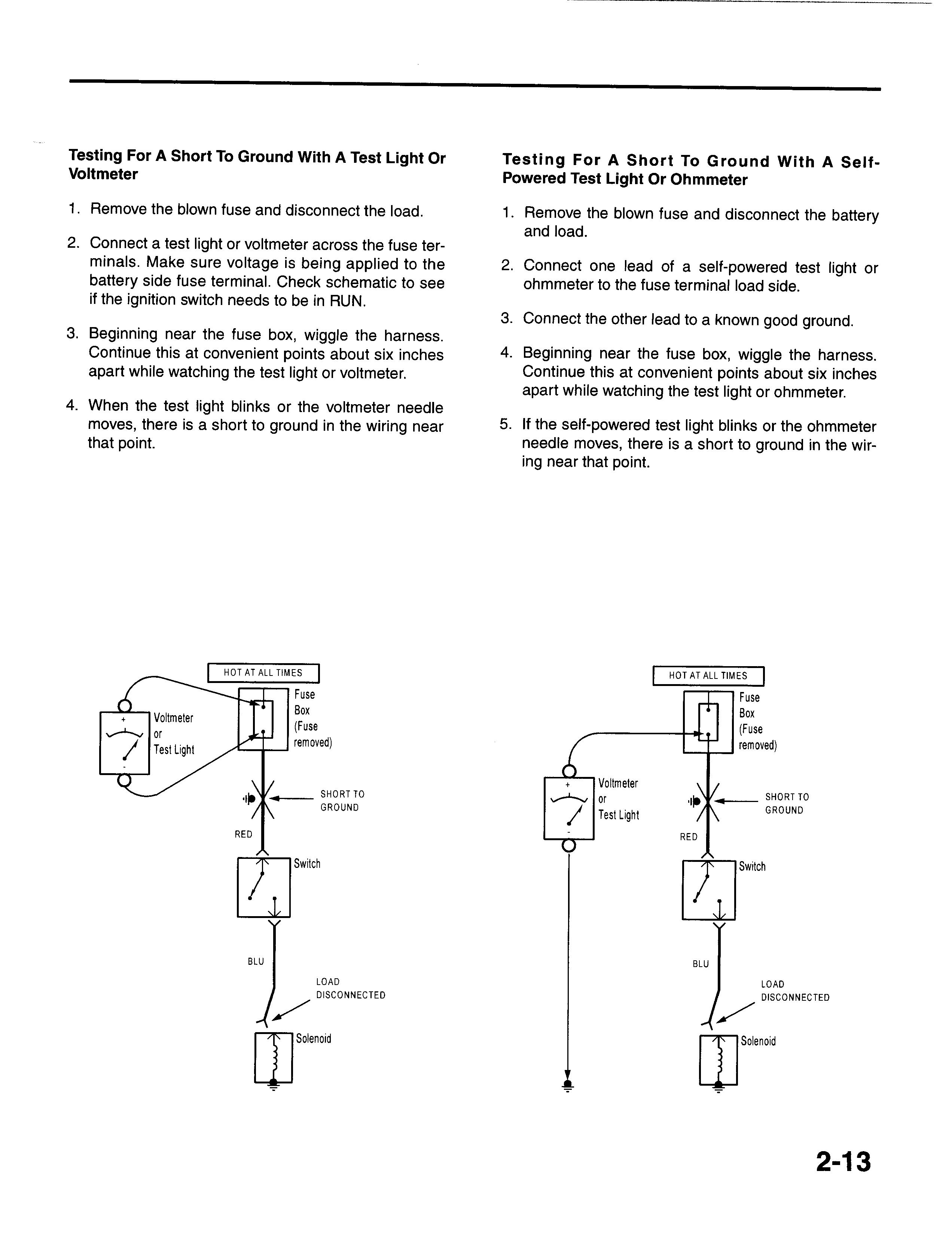
3. Connecttheotherleadtoa knowngoodground.
4. Beginningnearthefusebox,wiggletheharness. Continuethisatconvenientpointsaboutsixinches apartwhilewatchingthetestlightorohmmeter.
5. Iftheself-poweredtestlightblinksortheohmmeter needlemoves,thereisa shorttogroundinthewir¬ ingnearthatpoint.
1. Withthebatteryconnected,removetheblownfuse.

2. Connecttheshortfinderbetweenthepositivebat¬ teryterminalandtheloadsidefuseterminal.
3. Closeallswitchesinserieswiththewirethatyou aretroubleshooting.
4. Turnontheshorttinder.Thiswillsendpulsesofcur¬ renttotheshortandcreatea pulsingmagneticfield aroundthewiringbetweenthefuseboxandthe short.
5. Beginningatthefusebox,slowlymovetheshort findermeteralongthecircuitwiring.Themeterwill showcurrentpulsesthroughsheetmetalandbody trim.Aslongasthemeterisbetweenthefuseand theshort,theneedlewillmovewitheachcurrent pulse.Onceyoumovethemeterpastthepointof theshort,theneedlewillstopmoving.Check aroundthisareatolocatethecauseoftheshort circuit.


Isuzu Npr Nqr 2001 Electrical Troubeshooting-15i16489
Full download: http://manualplace.com/download/isuzu-npr-nqr-2001-electrical-troubeshooting-15i16489/

Fuse Number
F-1 F-2 F-3 F-4 F-5 F-6 F-7 F-8 F-9 F-10 F-11 F-12 F-13 F-14 F-15 F-16 F-17 F-18 F-19 F-20
HEATER
AIRCON
FuseName
EXHAUSTBRAKE(Diesel)
PCM(IGN)(Gas) D.R.L.(Diesel)
ENGINE(IGN)(Gas) ECU(BAT)(Diesel) A/TSOLENOID(GAS)
DOMELIGHT
TAILLIGHT STOPLIGHT HEADLIGHT(RH) HEADLIGHT(LH) WIPER,WASHER GENERATOR
TURNS/LIGHT
ECU(IGN)(Diesel)
PCM(ACC)(Gas)
AUDIO,CIGARLIGHTER
POWERSOURCE ENGINESTOP(Diesel)
FUELPUMP(Gas) HAZARD,HORN
ABS(BAT)
STARTER
Amps
25A 10A 10A 20A 10A 20A 10A 10A 10A 10A 20A 20A 20A 20A(Diesel) 10A(Gas) 10A 10A 20A 20A 10A 20A 20A(Diesel) 10A(Gas) 25A 10A
Heater
CircuitProtected
CompressorControls
ExhaustBrakeSystem(Diesel)
EngineControls(Gas) Headlights(Diesel) EngineControls(Gas) EngineControls(Diesel)
AutomaticTransmissionControls(Gas)
InteriorLights,ExteriorLights,SoundSystem(Gas), Speedometer(Gas)
DashLights,ExteriorLights BrakeLights
Headlights
Headlights
WindshieldWiper/Washer ChargingSystem
TurnLights EngineControls
CigaretteLighter,EngineControls,SoundSystem
EngineControls EngineStopSystem(Diesel) EngineControls,Gauges(Gas) EngineControls,Gauges,Horn,HazardLights
ABS
StartingSystem