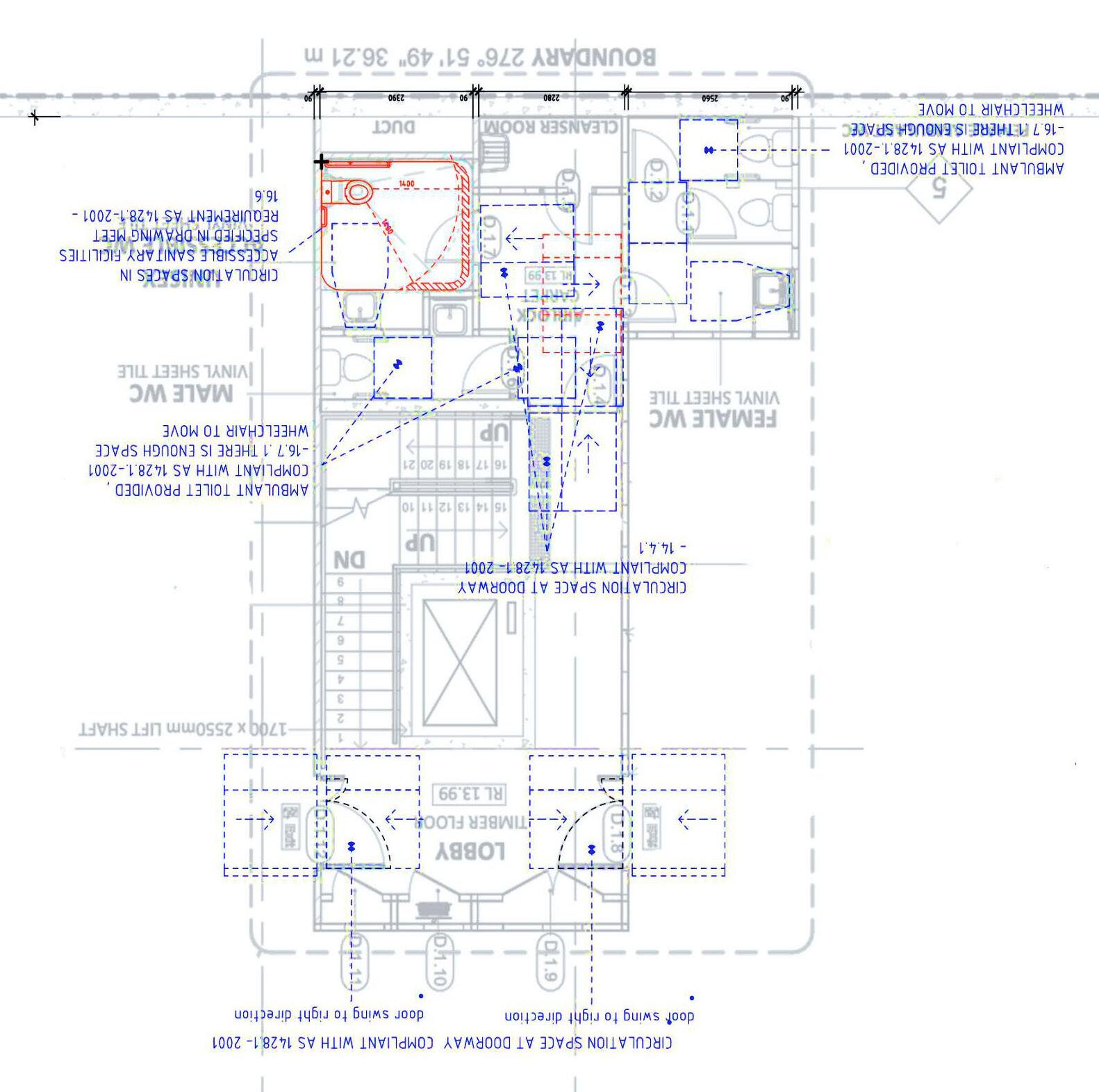
CLASSMATE’S REDESIGN - COMPLIANT TO AUSTRALIAN STADARD CHECK
GEORGE KARANTZALIS
S3728701
3


4
5
6
7
8
10
11
12
LYSAGHT KLIP-LOK 700 HI-STRENGTH®
Visually, a bold rib makes a strong statement rising from the flat pans. Thermal expansion of long, straight runs are achievable, and with no exposed fasteners, the long, straight lines of KLIP-LOK 700 HI-STRENGTH® (KL-700HS) remain clean and smooth.
At the heart of our system is our fixing clip, which can be laid in place and fixed simpler and faster than ever before. This is because the KLIP-LOK 700 HI-STRENGTH® clip is fixed with hex. Head screws, which are easier to drive. The clip also gives roofers the ability to accommodate up to 100mm of insulation.
KLIP-LOK 700 HI-STRENGTH® is available in rolled-on-site lengths. Our mobile on-site rollformer means extra long lengths of KLIP-LOK 700 HI-STRENGTH® can be made on-site and looks fantastic and also eliminates expansion joints. Longitudinal fluting manufactured from the mobile rollformer. Its availability is subject to enquiry.
INSTALLATION
PREPARATION
MATERIAL SPECIFICATIONS
Next generation ZINCALUME® aluminium/zinc/magnesium alloy coated steel complies with AS 1397:2011 G550, AM125 (550 MPa minimum yield stress, 125g/m minimum coating mass).
COLORBOND® is pre-painted steel for exterior roofing and walling. It is the most widely used. The painting complies with AS/NZS
2728:2013 and the steel base is an aluminium/zinc alloy-coated steel complying with AS 1397:2011. Minimum yield strengths is
G550 (550 MPa). Minimum coating mass is AM100 (100g/m ).
COLORBOND® Metallic is pre-painted steel for superior aesthetic qualities displaying metallic sheen.
COLORBOND® Ultra is pre-painted steel for severe coastal or industrial environments (generally within about 100-200 metres of the source). The painting complies with AS/NZS 2728:2013 and the steel base is an aluminium/zinc alloy-coated steel complying with AS 1397:2011. Minimum coating mass is AM150 (150g/m2).
SUPERDURA™ Stainless steel is a pre-painted steel and is used for severe and coastal environments. The painting complies with AS/NZS 2728:2013 and the steel base is stainless steel complying with AISI/ASTM Type 430; UNS No. S43000.
MATERIAL AND COLOUR AVAILABILITY
For local availability of KLIP-LOK 700 HI-STRENGTH in the base metal thicknesses or the large range of available finishes (from plain
ZINCALUME® steel to COLORBOND® pre-painted steel), contact your nearest Lysaght service centre.
For the local availability of colours for KLIP-LOK
shown). The first tower on the cut clip locates in the 1st rib of the first sheet (Figure 2) but you must fix two clips at the start.
Starting method 2. The first tower on the first clip locates in the first rib of the first sheet (Figure 2). The clip fixes the edge of the first sheet.
KLIP-LOK 700 HI-STRENGTH® INSTALLATION 1. Lay and fix wire mesh to the supports and glass wool insulation in accordance with the appropriate building requirements.
2. Position the first clips on each support by placing onto the support nearest the roof edge (Figure 3).
3. Fix the first clip on the support so they point in the direction of laying. Ensure the clip is 90 degrees to the edge of the sheet.
4. Align the clips using a string line (or the first sheet as a straight edge) to align the clips as you fix clip to each support working towards the high end of the roof.
5. Drive hex-head screws through the top of the clip, into the support.
6. Work along the edge of the roof ensuring it aligns correctly at its ends in relation to the gutter and ridge (or parapet or transverse wall).
7. Position the first sheet so that it overhangs the desired amount (usually 50mm) to the gutter. It is important to ensure this first sheet is placed square to adjacent edges (Figure 4). 8. Engage the sheet with clips using vertical foot pressure on all the ribs over each clip.
9. Fix the next row of clips, one to each support with the slots and tabs engaged. Be sure the clip is 90 degrees to the edge of the sheet. It is good practice to bend down the tabs once engaged. This can be done with the bit of a screw gun.
12. Fully engage the two sheets along the overlapping rib. You can do this by walking along the full length of the sheet with one foot in the centre pan of the previous sheet and the other foot applying vertical pressure to the top of the interlocking ribs at regular intervals. It is important that you don’t walk in the unsupported pan beside the overlap (Figure 5).
13. With long spans, additional care may be required to ensure the overlapping rib adequately engages onto the underlapping leg. Care should be exercised due to the potential instability of the side-lap when it is not adequately engaged (interlocked).
14. Similarly, engage all the clips by applying vertical foot pressure to the top of the other two ribs over each clip.
It is essential that the sheets interlock completely. It is important that your weight is fully on the sheet you are installing.
CHECK ALIGNMENT OCCASIONALLY
Occasionally check that the sheets are still parallel with the first sheet, by taking two measurements across the width of the fixed sheeting.
At about half way through the job, perform a similar check but take the measurements from the finishing line to aim for the final sheet to be parallel with the end of the roof. the measurements are not close enough, lay subsequent sheets very slightly out of parallel to gradually correct the error (Figure 6). Therefore, to allow this to happen, flatten the tabs on the base of subsequent clips—the slot in the clip will allow the clips to be fixed out of standard pitch.
FIX THE LAST SHEET the final space is less than the full width of sheet, you can cut a sheet along its length and shorten the clips as appropriate.
INSTALLING KLIP-LOK 700 HI-STRENGTH WALLS
In walling applications, horizontal pressure will need to be applied locally to the sheets to engage the ribs. Use body pressure (torso, hand or foot) or use a rubber mallet if required. Care should be exercised due to the potential instability of the temporary worker access equipment.
To prevent KLIP-LOK 700 HI-STRENGTH from sliding downward in the fixing clips, you should pierce-fix through each sheet under the flashing or capping, along the top of the sheets.
LOK-KLIP® AND KLIP-LOK 700 HI-STRENGTH
The new LOK-KLIP system provides installers with quick and easy end joint/expansion joint solution. For more details refer to the
WALKING ON ROOFS
Keep your weight evenly distributed over the soles of both feet to avoid concentrating your weight on either heels or toes. Always wear smooth soft-soled shoes; avoid ribbed soles that pick up and hold small stones, swarf and other objects. Be careful when moving between supports. Do not walk in the pan immediately adjacent to flashings or translucent sheeting. Walk at least one pan away.
MAINTENANCE Optimum product life will be achieved all external walls are washed regularly. Areas not cleaned by natural rainfall (such as the tops of walls sheltered by eaves) should be washed down every six months.
STORAGE AND HANDLING
Keep the product dry and clear of the ground. If stacked or bundled product becomes wet, separate it, wipe it with clean cloth to dry thoroughly.
Handle materials carefully to avoid damage: don’t drag materials over rough surfaces or each other; don’t drag tools over material; protect from swarf.
METAL & TIMBER COMPATIBILITY
Lead, copper, free carbon, bare steel and green or some other chemically-treated timbers are not compatible with this product. Don’t allow any contact of the product with those materials, nor discharge of rainwater from them onto the product. Supporting members should be coated to avoid problems with underside condensation. there are doubts about the compatibility of other products being used, ask for advice from our information line.
CUTTING
For cutting thin metal on site, we recommend a circular saw with metal-cutting blade because it produces fewer damaging hot metal particles and leaves less resultant burr than does carborundum disc.
Cut materials over the ground and not over other materials.
TURN UP-DOWN TOOLS
On all roofs of pitches less than 15 degrees, the high end of all sheets must be turned up to stop water from being driven under the flashing and into the building.
Similarly, the pans at the gutter end must be turned down to stop water running back along the underside of the sheets.
Tools are available for both applications.
ROOF
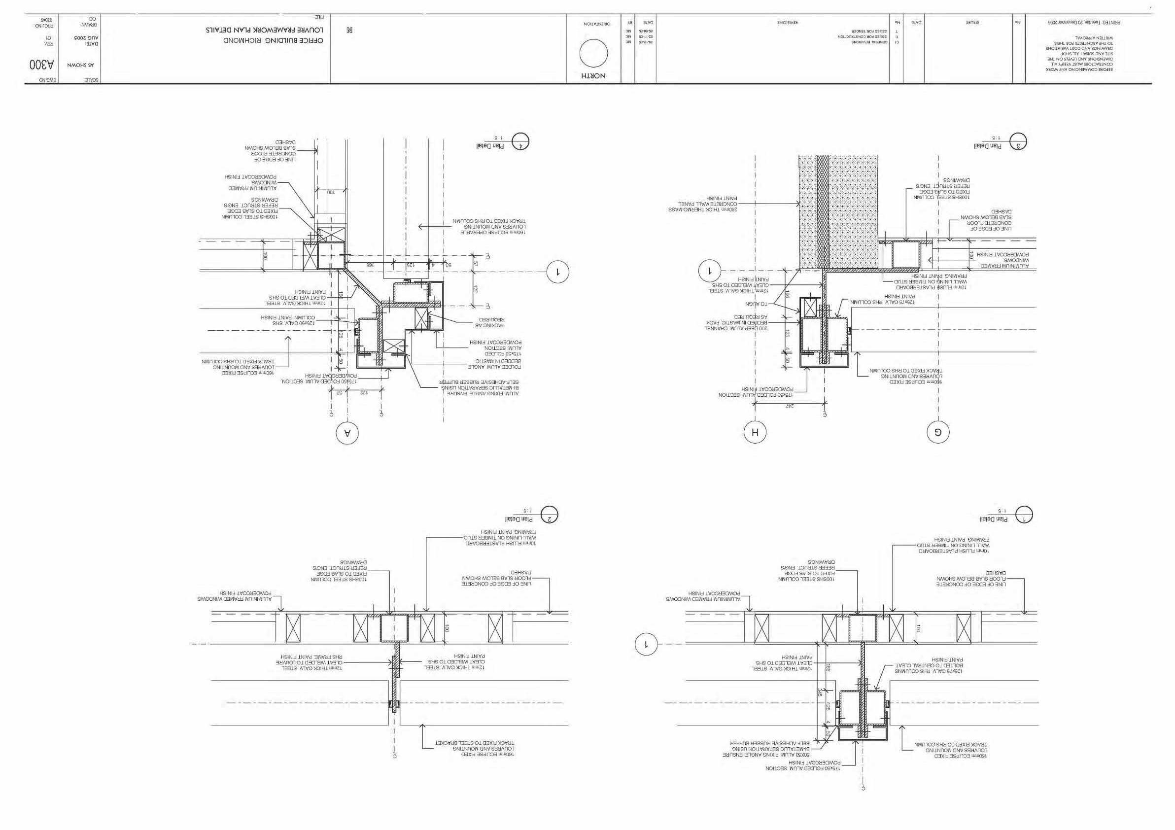
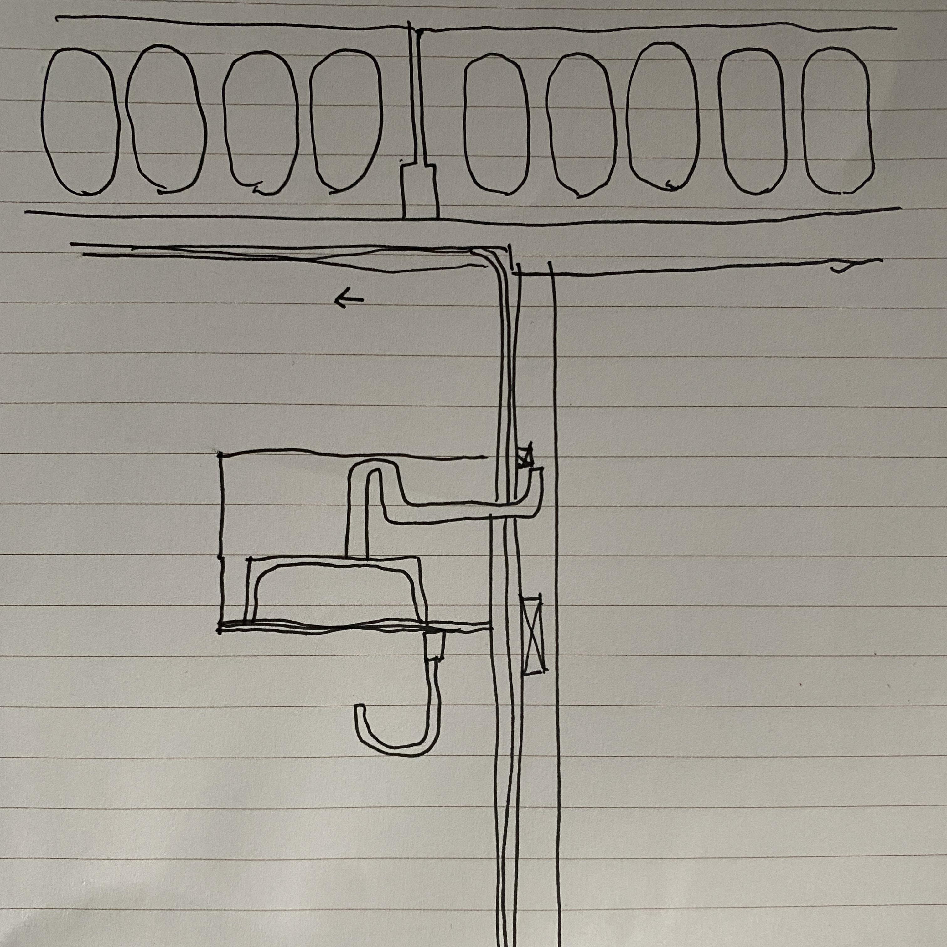
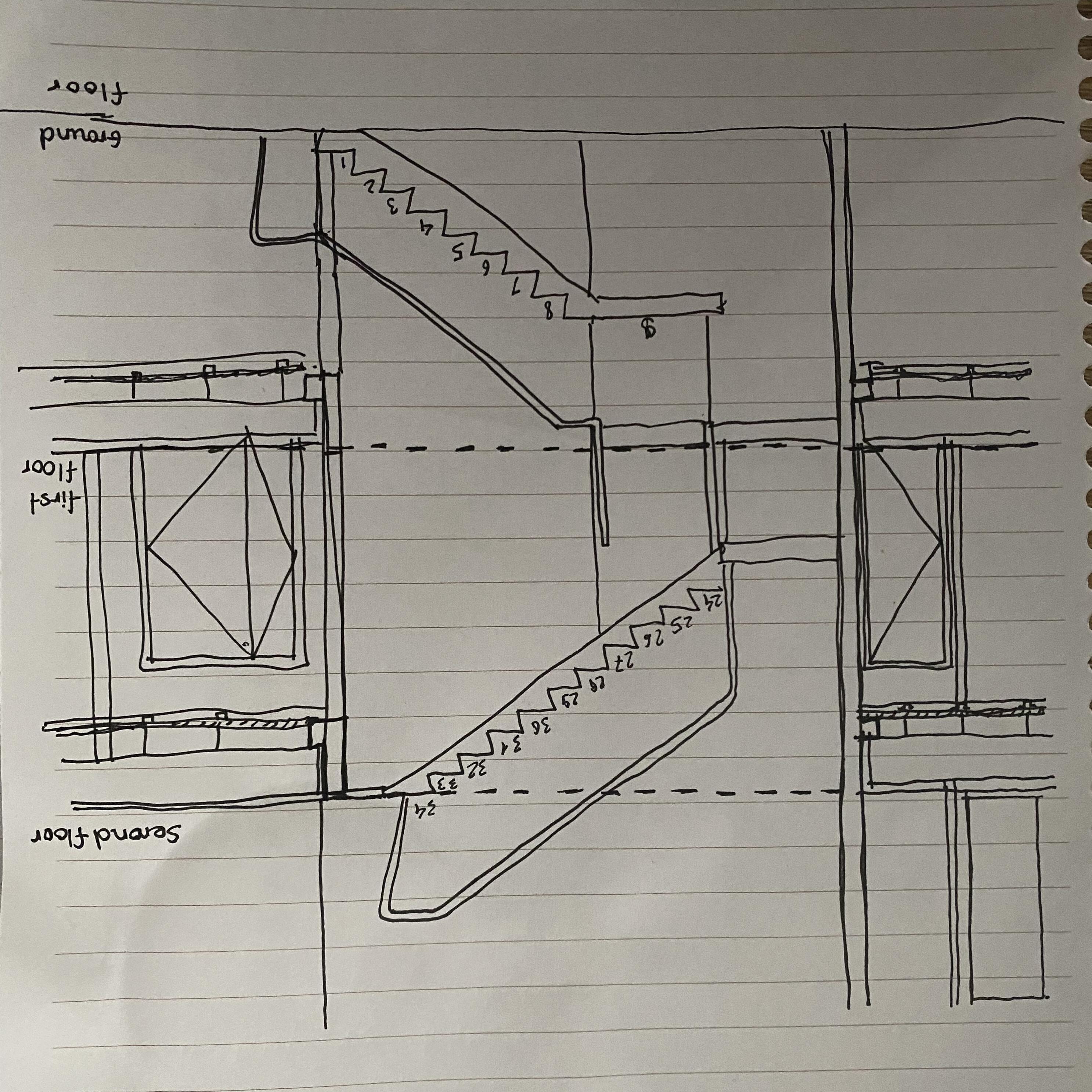
MANUFACTURE SPECIFICATION & HAND SKETCHES
13 3 KLIP-LOK 700 HI-STRENGTH ® TOLERANCES Length: + 0mm, 15mm; Width: + 4mm, 4mm Make allowance for thermal expansion or contraction for long length roofs at sheeting ends. The equation = x T L gives an indication of the sheeting extent or contraction L). = 12 x 10-6 (coefficient of linear expansion for steel) T = temperature change in °C = sheet length in mm MAXIMUM SUPPORT SPACINGS The maximum recommended support spacings are based on testing in accordance with AS 1562.1-1992, AS 4040.0-1992 and AS 4040.1-1992. Roof spans consider both resistance to wind pressure and light roof traffic (traffic arising from incidental maintenance). Wall spans consider resistance to wind pressure only. The pressure considered is based on buildings up to 10m high in Region B, Terrain Category 3, M =0.85, M =1.0, M =1.0 with the following assumptions made: ROOFS: Cpi=+0.20, Cpe=-0.90, K =2.0 for single and end spans, K =1.5 for internal spans. WALLS: Cpi=0.20, Cpe=-0.65, K =2.0 for single and end spans, K =1.5 for internal spans. These spacings may vary by serviceability and strength limit states for particular projects. MAXIMUM SUPPORT SPACINGS (MM) BMT Type of Span 0.42mm 0.48mm Roofs Single span 1650 2050 End span 1750 2350 Internal span 2200 2800 Unstiffened eaves overhang 150 200 Stiffened eaves overhang 450 500 Walls Single span 2600 3000 End span 3000# 3000# Internal span 3000# 3000# Overhang 150 200 For roofs: the data are based on foot-traffic loading. For walls: the data are based on pressures for transverse fluted material. Table data are based on supports of 1mm BMT. Refer to the TOPSPAN Design and Installation Guide and Selection Tables for support thickness less than 1.0 mm BMT, or seek advice from our information line. Spans in excess of 3000mm may be available subject to enquiry. Wall applications or long spans require particular attention to installation practice. SPAN TYPES MAXIMUM ROOF LENGTHS FOR DRAINAGE MEASURED FROM RIDGE TO GUTTER Penetrations will alter the flow of water on a roof. For assistance in design of roofs with penetrations, please seek advice from our information line. LIMIT STATES WIND PRESSURES KLIP-LOK 700 HI-STRENGTH offers the full benefits of the latest methods for modelling wind pressures. The wind pressure capacity table is determined by full scale tests conducted at Lysaght’s NATAregistered testing laboratory, using the direct-pressure testing rig. Testing was conducted in accordance with AS 1562.1:1992 Design and Installation of Sheet Roof and Wall Cladding—Metal, and AS 4040.2:1992 Resistance to Wind Pressure for Non-cyclonic Regions. The pressure capacities for serviceability are based on a deflection limit of (span/120) + (maximum fastener pitch/30). The pressure capacities for strength have been determined by testing the cladding to failure (ultimate capacity). These pressures are applicable when the cladding is fixed to minimum of 1.0mm, G550 steel. For material less than 1.0mm thick, refer to the TOPSPAN® Design and Installation Guide and Selection Tables, or seek advice from our information line. ADVERSE CONDITIONS this product is to be used in marine, severe industrial, or unusually corrosive environments, ask for advice from our information line. MAXIMUM ROOF LENGTHS FOR DRAINABLE MEASURED FROM RIDGE TO GUTTER (M) Peak Rainfall Intensity (mm/hr) Roof Slopes (degrees) 2 3 5 7.5 10 100 344 428 502 624 745 856 150 229 285 334 416 496 571 200 172 214 251 312 372 428 250 137 171 201 250 298 342 300 115 143 167 208 248 285 400 86 107 125 156 186 214 500 69 86 100 125 149 171 MINIMUM ROOF PITCH Our unique anti-capillary side-lap allows you to use KLIP-LOK 700 HI-STRENGTH® on roof pitches from as low as 1° (1 in 50) for 0.48 and 2° for 0.42 BMT. NON-CYCLONIC AREAS The information in this brochure is suitable for use only in areas where a tropical cyclone is unlikely to occur as defined in AS 1170.2:2002. For information on the use of LYSAGHT® products in cyclonic conditions, refer to the Cyclonic Area Design Manual which is available on our website: www.lysaght.com. Roofing Walling Profiles Endspans endlap expansionjoint sheeting Step Spacing definitions End Span Internal Span Overhang Single Span Walling Profiles Only O 2 KLIP-LOK 700 HI-STRENGTH ®
700 HI-STRENGTH® please enquire at your nearest Lysaght service centre. 700mm cove 43mm COLORBOND® STEEL WITH THERMATECH® TECHNOLOGY THERMATECH solar reflectance technology is now included in the standard COLORBOND® steel palette. COLORBOND® steel with THERMATECH technology reflects more of the sun’s heat, allowing both roofs and buildings stay cooler in summer. In moderate to hot climates, compared to roofing materials of similar colour with low solar reflectance, COLORBOND® steel with THERMATECH® can reduce annual cooling and energy consumption by up to 20%. LENGTHS Mobile rollformed sheets are custom cut on-site. Factory sheets cut to order. MASSES BMT (mm) kg/m kg/m m /t ZINCALUME steel 0.42 3.23 4.61 217 COLORBOND steel 0.42 3.26 4.65 215 ZINCALUME steel 0.48 3.67 5.24 191 COLORBOND steel 0.48 3.70 5.28 189 5 KLIP-LOK
700 HI-STRENGTH ®
Before starting work ensure that: • check flatness, slope and overhang; • orient the sheets before lifting. Note the overlapping rib is towards the end of the building where you start; check that the overhang of the sheets from the clips, at both eaves and ridge, is not less than the minimum permitted. the first and the last supports and clips should be at least 75mm from each end of the sheet to keep maximum holding power. Make any necessary adjustments before you start laying sheets, because they will be difficult to rectify later. ORIENT SHEETS BEFORE LIFTING Consider which end of the building is best to start from. For maximum weather-tightness, start laying sheets from the end of the building that will be downwind of the worst-anticipated or prevailing weather (Figure 1). It is much easier and safer to turn sheets on the ground than up on the roof. Before lifting sheets on to the roof, check that they are the correct way up and the overlapping side is towards the edge of the roof from which installation will start. Place bundles of sheets over or near firm supports, not at mid span of roof members. Starting method 1. Cut the 1st clip 25mm from the centre of the second tower (as
Overlapping rib Underlapping rib Figure 4 Placing the first sheet. Prevailing weathe Direction of laying Sheet Sheet 2 Sheet 3 Discard Second clip Second clip First clip 25mm Standar flashin Towers Standar flashin cut her KLIP-LOK 700HS: Starting method KLIP-LOK 700HS: Starting method 2 KLIP-LOK 700 HI-STRENGTH® Figure 1 Lay sheets towards prevailing weather. Figure 2 Alternative methods for first clips. Figure 3 Fix the first row of clips. Fix the next (and subsequent) clips and sheets. 4 KLIP-LOK 700 HI-STRENGTH ® KLIP-LOK 700 HI-STRENGTH® (TRANSVERSE FLUTES) LIMIT STATE WIND PRESSURE CAPACITIES (KPA) 0.42 BMT Span Type Limit State Span (mm) 900 1200 1500 1800 2100 2400 2700 3000 Single Serviceability 3.08 2.53 2.00 1.53 1.15 0.86 0.65 0.49 Strength* 4.95 4.15 3.50 2.85 2.30 1.85 1.55 1.30 End Serviceability 3.05 2.73 2.40 2.02 1.64 1.32 1.07 0.91 Strength* 5.55 4.30 3.35 2.75 2.55 2.40 2.20 1.85 Internal Serviceability 2.90 2.64 2.39 2.16 1.94 1.74 1.55 1.38 Strength* 5.40 4.60 3.90 3.25 2.75 2.40 2.20 2.00 KLIP-LOK 700 HI-STRENGTH® (TRANSVERSE FLUTES) LIMIT STATE WIND PRESSURE CAPACITIES (KPA) 0.48 BMT Span Type Limit State Span (mm) 900 1200 1500 1800 2100 2400 2700 3000 Single Serviceability 4.22 3.35 2.54 1.83 1.28 0.90 0.69 0.57 Strength* 6.30 5.20 4.25 3.35 2.70 2.15 1.80 1.60 End Serviceability 3.81 3.34 2.88 2.43 2.02 1.67 1.38 1.15 Strength* 6.30 5.10 4.15 3.55 3.15 2.85 2.50 2.20 Internal Serviceability 3.76 3.32 2.91 2.54 2.24 2.01 1.84 1.68 Strength* 6.35 5.55 4.80 4.10 3.60 3.20 2.85 2.60 KLIP-LOK 700 HI-STRENGTH® (LONGITUDINAL FLUTES) LIMIT STATE WIND PRESSURE CAPACITIES (KPA) 0.42 BMT Span Type Limit State Span (mm) 900 1200 1500 1800 2100 2400 2700 3000 Single Serviceability 2.52 2.05 1.60 1.22 0.91 0.69 0.56 0.48 Strength* 4.85 4.10 3.40 2.75 2.20 1.80 1.45 1.20 End Serviceability 2.65 2.48 2.26 1.92 1.53 1.19 0.94 0.79 Strength* 3.40 2.95 2.60 2.30 2.15 2.00 1.80 1.55 Internal Serviceability 2.63 2.40 2.17 1.96 1.76 1.57 1.41 1.25 Strength* 3.85 3.40 3.00 2.65 2.35 2.15 2.00 1.95 KLIP-LOK 700 HI-STRENGTH® (LONGITUDINAL FLUTES) LIMIT STATE WIND PRESSURE CAPACITIES (KPA) 0.48 BMT Span Type Limit State Span (mm) 900 1200 1500 1800 2100 2400 2700 3000 Single Serviceability 2.80 2.27 1.77 1.33 0.98 0.74 0.59 0.50 Strength* 5.80 4.75 3.80 2.95 2.30 1.80 1.50 1.30 End Serviceability 3.11 2.51 2.01 1.64 1.40 1.23 1.07 0.93 Strength* 5.10 4.05 3.20 2.65 2.30 2.10 1.85 1.60 Internal Serviceability 2.68 2.47 2.27 2.09 1.94 1.81 1.70 1.60 Strength* 5.00 4.30 3.65 3.10 2.70 2.45 2.35 2.30 * Above tables are based on supports of 1mm BMT. 7 KLIP-LOK
HI-STRENGTH
®
FASTENERS WITHOUT INSULATION Fix to Steel Single & lapped steel thickness 0.55 up to 1.0mm BMT Fix to Steel Single steel thickness 1.0mm BMT up to 3.0mm BMT Fix to Steel Total lapped thickness 1.00 BMT up to 3.8mm BMT Fix to Timber Hardwood J1-J3 Fix to Timber Softwood J4 Clip Fixed RoofZips M6-11x25 12-14x20*, Metal Teks, HH 12-14x20*, Metal Teks, HH 12-11x25, Type 17, HH 12-11x45, Type 17, HH or RoofZips M6-11x25 Notes: 1. For other steel thicknesses not specified please seek advice from screw manufacturer. 2. HH = Hex. Head. 3. Use screws per clip. 4. As above or equivalent fastener. * Longer screws may be easier to install (e.g. 12-14x30). 6 KLIP-LOK 700 HI-STRENGTH 10. As before, place the next sheet over its clips ensuring you also engage the edge of the preceding sheet. 11. Accurately position the sheet so that it overhangs the desired amount into the gutter. It is important that you keep the gutter-end of all sheets in straight line.
LOK-KLIP® brochure available on our website (Figure 7). INSTALLING TRANSLUCENT SHEETS WITH KLIP-LOK 700 HI-STRENGTH® Because of its greater thermal expansion, translucent cladding should be fixed using oversized holes and sealing washers recommended by the cladding manufacturer. When used with concealed fixed claddings, ensure the fasteners do not penetrate the steel cladding. There are translucent products available that easily accommodate this. Note: Don’t exceed the maximum support spacing specified by the translucent cladding manufacturer. Use of translucent sheeting may result in lower limit state capacities. For installation of translucent sheets with LOK-KLIP refer to the Ampelite Clearslide® installation guidelines on LOK-KLIP Don't step in this pan until ribs are engaged Figure 5 Engaging the lapping ribs. Figure 6 Check alignment occasionally. Start Finis h Fixed sheets Purli Later checks Early checks Later checks Early checks Figure 7 LOK-KLIP® and KLIP-LOK 700 HI-STRENGTH® LOK-KLIP bracket Weather strip Rib of cladding
