05 CONSTRUCTION: STAIRS


Prepared by : Checked by Approved by

1.1.1
which doc should I follow?
For the purpose of this construction booklet, we will be using the International Building Code (IBC) as the information basis, as well as the National Fire Protection Association (NFPA) for egress requirements. However, please bear in mind that different geographies and different typologies call for different Regulation documents and Codes.
The International Building Code is a model building code created by the International Code Council (ICC, an American nonprofit standards organization sponsored by the building trades). The IBC has been adopted for use as a base code standard by most jurisdictions in the United States. Despite its name, the International Code Council is not an international organization, its codes are rarely used outside the United States, and its regulations do not consistently follow international best practices.
According to the ICC, the IBC is intended to protect public health and safety while avoiding both unnecessary costs and preferential treatment of specific materials or methods of construction. The code is updated every three years.
In the International Building Code (IBC), stairs are primarily governed by Chapter 10: Means of Egress. This chapter covers the design, construction, and requirements for all components related to the safe movement of people through a building, including stairs, ramps, corridors, doors, and exits.
1.1 International Building Code which doc should I follow?
1. This section outlines the general requirements for stairways, including minimum and maximum dimensions, structural requirements, and safety features. Key considerations include:
• Tread and Riser Dimensions: Specifies the maximum and minimum dimensions for the tread (step depth) and riser (step height).
• Handrails: Stairs must have handrails where required, and this section details the height, placement, and clearances for handrails.
• Headroom: Stairs must provide a minimum clear headroom,
• Width: Minimum stair width
• Details the construction of stairs, including how they should be built to ensure they meet safety standards. It covers structural requirements for materials and framing as well as ensuring the stairs provide a safe, durable path for users.
• While specifically about ramps, this section often intersects with stair design in terms of accessibility requirements. For buildings where stairs cannot be used by individuals with disabilities, a ramp or other accessible means of egress is required
• Requires that stairways have level landings at the top and bottom for safety and ease of use. The minimum landing depth is typically at least the width of the stairway.
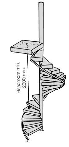
• This section specifically addresses the design and use of spiral stairways, which have different dimension and space requirements compared to traditional straight staircases.
3. It outlines the minimum width of stairs to accommodate the expected number of people in a building. This section ties directly into occupant load calculations and egress requirements.
• Section 1005: Egress Width
This section discusses the required width of egress components, including stairs, to accommodate a certain number of occupants. This ensures safe evacuation in case of an emergency.
• Section 1023: Enclosures for Stairs
This section deals with the enclosure and fire-resistance requirements of stairwells, particularly for stairways in high-rise buildings. It ensures that stairways are protected from smoke and fire to maintain safe egress during emergencies.
• Section 3402: Accessibility (ADA Requirements)
While not in Chapter 10, the Americans with Disabilities Act (ADA) requirements are often cross-referenced in the IBC, especially when it comes to providing accessible routes in and around stairways (like ramps and elevators for individuals with mobility challenges).
The IBC is updated every few years, so it’s always important to check the latest edition for any changes in stair design requirements.
^ Online ICC site for consulting the IBC which doc should I follow?

which doc should I follow?

1.2.1 What is the NFPA?
The National Fire Protection Association (NFPA) is a U.S.-based organization that develops and publishes codes and standards to reduce fire and life safety risks in buildings. Regarding building regulations, the NFPA provides essential guidelines especially through documents like NFPA 101 (Life Safety Code) that influence how buildings are designed, constructed, and maintained to ensure safe evacuation, fire protection, and emergency response. These standards are widely used in the U.S. and internationally, often alongside local building codes..
1.2.2 Stairs in the NFPA – Chapter 7: Means of Egress
This chapter provides comprehensive requirements for the design, construction, and protection of means of egress, which includes stairs. The goal is to ensure that in case of fire or emergency, building occupants can safely and efficiently evacuate. Key NFPA Stair-Related Requirements in Chapter 7:
1. Stair Dimensions:
• Minimum width: about 1120 mm for stairs serving an occupant load of more than 50; 915 mm if serving fewer.
• Tread depth and riser height: Typically matches IBC closely — max riser of 7 inches (180 mm), min tread depth of 11 inches (280 mm).
2. Stair Enclosures: Stairs used as part of the means of egress in buildings (especially multi-story) often must be enclosed with fire-rated construction. Additionally, 2-hour fire-resistance rating for stairs serving four or more stories is a common requirement.
3. Continuity of Egress:
• Stairs must connect continuously from floor to floor without obstruction or dead ends.
• Discharge from stairs must lead to a public way or a safe area.
4. Handrails
• Must be provided on both sides of the stairway.
• Height between 34 and 38 inches above the leading edge of the treads.
• Ends must return to the wall or floor to avoid catching clothing.
5. Headroom: Minimum of 6 feet 8 inches (2030 mm) clearance is required throughout the stair path.
6. Emergency Lighting and Exit Signs
• Must include illumination for stairs during emergency conditions (power failure).
• Exit signage must be clearly visible and placed according to visibility requirements.
7. Smokeproof Enclosures (Section 7.2.3.9): For high-rise buildings, stairwells must be designed to be smokeproof mechanically ventilated or naturally ventilated enclosures to allow safe evacuation.
1.2 National Fire Protection Association which doc should I follow?
1.2.2 Stairs in the NFPA – Chapter 7: Means of Egress
Special Considerations
• Accessible Means of Egress: In addition to stairs, alternate accessible egress routes (like elevators with standby power or evacuation platforms) must be considered.
• Occupant Load Calculations: NFPA sets guidelines on how many people a stair must be able to accommodate during evacuation.
1.2.3 Other NFPA documents that may affect stair design
• NFPA 5000 – Building Construction and Safety Code: Comprehensive building code that includes stair and egress provisions similar to NFPA 101
• NFPA 13: Impacts stair design indirectly through requirements for sprinkler coverage
• NFPA 70 (NEC): Ensures that lighting and emergency systems for stairs are correctly wired
* Use NFPA 101 alongside local building codes like the IBC or country-specific standards (e.g., DIN, Eurocode).
* NFPA is often adopted or modified by local fire marshals or authorities having jurisdiction (AHJ) always consult them for approval.
* Apply it especially in hospitals, schools, public buildings, and high-rise constructions, where fire safety and evacuation efficiency are critical.
which doc should I follow?
When designing stairs in Europe, several international and European regulations and standards guide the design to ensure safety, accessibility, and proper functionality. The specific regulations can vary by country, but some of the most commonly referenced standards include:.
For stairs made from steel or other materials, this standard provides guidance on the design of structural elements, including stair supports and load-bearing systems.
1.3.1
The Eurocode is a set of European standards that provide guidelines for the design of buildings and civil engineering works. It covers various aspects of structural design, including loads, materials, and safety considerations, ensuring that buildings are safe, stable, and sustainable across Europe. The Eurocodes are harmonized across EU member states, allowing for consistency and standardization in construction practices. They are split into several parts (such as Eurocode 1 for loads, Eurocode 2 for concrete, Eurocode 3 for steel, etc.) to address different structural elements and materials. These standards are often complemented by national regulations that adapt the Eurocodes to specific local conditions.
This code deals with the actions (loads) that structures, including stairs, must be able to support. It includes factors such as live loads (the load of people using the stairs) and the design of stairways to accommodate those loads.
For stairs that incorporate masonry elements, this standard provides the necessary requirements for the structural integrity of masonry construction.
This is a more specific European standard that deals with the design and construction of staircases. It provides guidelines for dimensions, safety, and functionality, such as step height, width, and handrail requirements.
This regulation ensures that public buildings and transportation infrastructures are accessible to people with disabilities, which includes considerations for stair design (such as the use of lifts or ramps in conjunction with stairs, and specific dimensions to make stairs safer and easier to navigate).
Although not specific to stairs alone, ISO 7250 provides general guidelines on dimensions for architectural elements, which can influence stair design in terms of overall measurements and space allowances.
Each country in Europe may have its own set of national building codes that implement or adapt the European standards.
1. In Germany, the Musterbauordnung (MBO) and DIN 18065 (staircase design) are commonly applied. The DIN standards (Deutsches Institut für Normung) are a set of German standards that provide technical specifications and guidelines for various aspects of engineering, manufacturing, and construction. In the context of building regulations, DIN standards cover a wide range of topics, including structural design, materials, safety, and performance requirements for buildings and infrastructure. These standards are widely used in Germany and can influence or complement other European and international regulations, such as the Eurocodes. They ensure that construction projects are safe, reliable, and built to consistent, high-quality standards.
2. In France, the Règlement de sécurité contre l’incendie and the Code de la Construction et de l’Habitation apply.
3. In the UK, the Building Regulations Part K and BS 5395 (the British Standard for stairs) are used for stair design.
4. In Belgium, the Belgian General Regulation on Buildings (Règlement Général sur les Bâtiments / Algemeen Reglement op de Arbeidsbescherming – ARAB) is used for stair design.

5. In Poland, the Warunki Techniczne (Rozporządzenie w sprawie warunków technicznych, jakim powinny odpowiadać budynki i ich usytuowanie)
6. In the Netherlands, Bouwbesluit 2012 (Dutch Building Decree 2012)
7. In Spain, the CTE (Código Técnico de la Edificación), Some Key Parts of the CTE for Stair Design are
DB-SU – Seguridad de Utilización (Safety in Use)
•Regulates stairs in terms of safety, comfort, and usability.
•Covers stair dimensions, slip resistance, handrails, landings, and lighting.
•Applies to both residential and public buildings.
DB-SI – Seguridad en caso de Incendio (Fire Safety)
•Defines stair requirements for emergency evacuation, fire-rated enclosures, and protected stairwells.
•Includes rules for stair design in high-rise or complex buildings.
DB-HS – Salubridad (Health and Hygiene)
•Occasionally relevant for stairs in service areas (e.g., preventing water accumulation, ventilation of stairwells).
1.5 Unified Facilities Criteria (UFC).
which doc should I follow?
In the United States Department of Defense (DoD) context, stair design for military and federal facilities is governed by the These are standardized codes and guidelines used across the Army, Navy, Air Force, and other DoD agencies.
Here are the most relevant UFC documents that address stairs design, especially regarding safety, dimensions, accessibility, and egress:
UFC Document Title
UFC 1-200-01
DoD Building Code (General Building Requirements)
UFC 3-600-01 Fire Protection Engineering for Facilities
UFC 4-010-01 DoD Minimum Antiterrorism Standards for Buildings
UFC 4-021-01
Adopts and modifies the International Building Code (IBC) for DoD use. All stair design must meet the IBC, with DoD-specific amendments.
Covers egress stairs, exit enclosures, stair fire resistance, and smokeproof towers. Based on NFPA 101.
Requires features such as progressive collapse resistance and may influence stair core design for structural integrity.
Design and O&M: Mass Notification Systems May impact stairways as evacuation routes with required visual/audible alarms.
UFC 3-120-01 Design: Sign Standards
UFC 3-101-01 Architecture
Addresses signage for stairs and egress pathways in accordance with safety and wayfinding standards.
Provides architectural guidelines for space planning, including stair location, dimensions, and finishes.
UFC 4-171-05 Design Guide for Military Correctional Facilities Includes specific stair safety and security requirements for controlled environments.
UFC 3-190-06
Protective Coatings and Finishes
Important for slip resistance and finish durability in stair treads and landings.
1.6 Table of resources which doc should I follow?
Key Section Keywords
Stairway Construction dimensions, riser/tread, headroom, width
Handrails gripping, height, extensions
Guards and Protection guardrails, fall protection
Means of Egress General definitions, design criteria
Exit Access & Egress Width minimum width, capacity
NFPA Stair Requirements interior stairs, emergency stairs, width
Code Reference
IBC Section 1011
IBC Section 1014
IBC Section 1015
IBC Section 1003
IBC Section 1005
NFPA 101 Chapter 7.2.2 (search “7.2.2” once document is open)
Means of Egress Components exit enclosures, stairways, travel distance
NFPA 101 Chapter 7 (search “Chapter 7”)
New Construction Requirements new buildings, exit stairs, guards
NFPA 101 Chapter 2 & 3 (definitions & occupancies)
Note 1: Direct links to specific NFPA code sections require access via subscription or organizational access through NFPA.org. You can open the full code and use the search function for specific sections like "7.2.2."
Note 2: Host nation requirements to be compared with international requirements, complying with most restrictive requirement. Decision shall be compiled in code compliance matrix.
1.7 Table of general requirements according to regulations which doc should I follow?
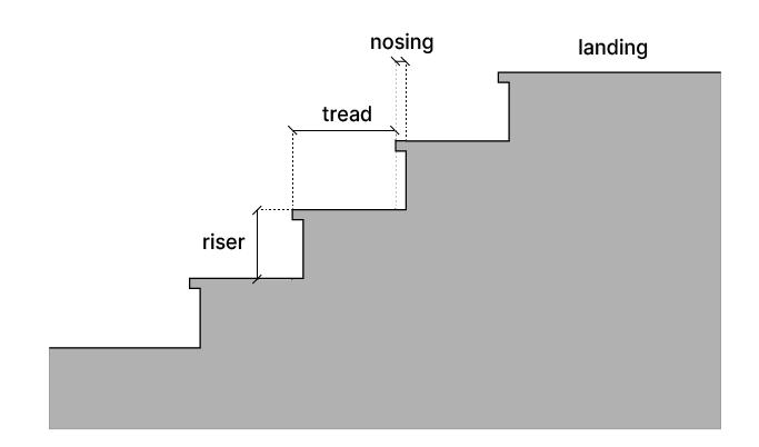
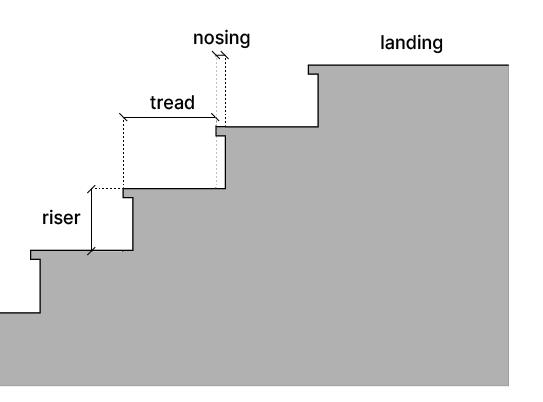
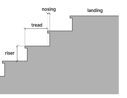
Contrast on Nosings
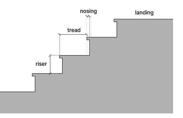
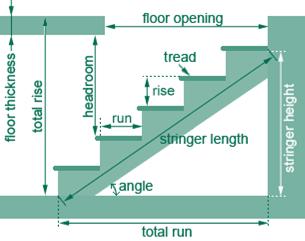
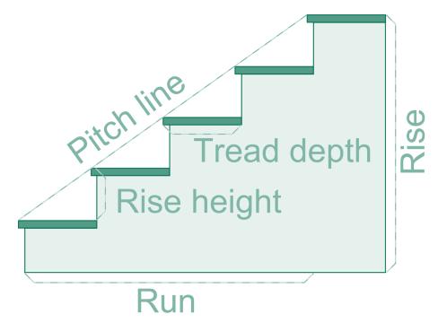
1. Riser: The vertical height of each individual step. It determines how steep or gradual the staircase is.
Typical Range: 175–200 mm is standard for residential stairs. Commercial stairs may have a slightly lower riser for easier use.
2. Tread: The horizontal part of the step where you place your foot. It affects the comfort of the stair.
Typical Range: 250–300 mm is common for residential stairs.
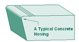
3. Nosing: The edge of the tread that overhangs the riser below it. It helps people step down or up more easily.
Typical Range: Typically, around 25–40 mm of overhang.
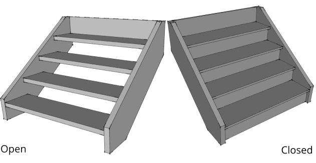
4. Stringer: The structural support that runs along the sides of the stairs, holding the treads and risers in place.
Types: Open stringers (visible, often decorative) and closed stringers (concealed behind the stairs).
5. Landing: A flat platform at the top or bottom of a staircase, or between flights of stairs. It provides a rest point and helps with direction changes.
Typical Requirement: Landings are required at the top and bottom of stairs and where the direction changes (e.g., at 90-degree turns).
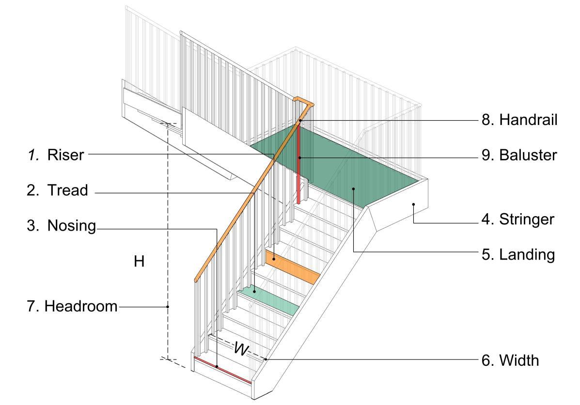
6. Width: The horizontal distance across the staircase, determining how many people can safely use it at once.
Typical Range: 920–1120 mm for commercial buildings; residential stairs can be narrower
6.1. Clear width: The unobstructed, usable width of a stairway measured from wall to wall or between handrails or guardrails, depending on the configuration
7. Headroom: The vertical clearance above the stair tread, ensuring that users don't hit their heads when walking up or down.
Typical Range: A minimum of 2 meters of headroom is standard.
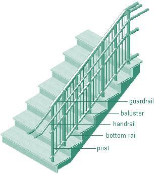
8. Handrail: A support rail that runs along one or both sides of the staircase to provide stability and prevent falls. *
Typical Height: 865–965 mm from the stair nosing.
8.1. Handrail extension: The portion of a handrail that continues beyond the top or bottom of the stair flight. It provides additional support and safety as users begin to ascend or complete their descent on the stairs.
* REFER TO CHAPER 8 FOR FURTHER INFORMATION ABOUT HANDRAILS, BALUSTERS, GUARDRAILS AND RAILING EXTENSIONS
8.1.Handrail extension
9. Baluster (or Spindle): The vertical posts or supports that hold up the handrail.
Spacing: Balusters are typically spaced to prevent children from passing through, often no more than 100 mm apart.
10. Guardrail: protective barrier installed along the open sides of a stairway to prevent falls to lower levels. It is required when the vertical drop exceeds 30 inches (762 mm) and must be at least 42 inches (1067 mm) high, measured vertically from the leading edge of the stair tread.
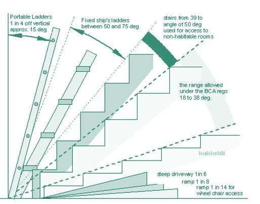
11. Pitch (Slope): The angle or slope of the staircase, which is determined by the ratio of the riser to the tread. A steeper staircase has a higher pitch. Typical Range: Stair angles usually range from 30° to 40°.
8. Handrail
10. Guardrail
* REFER TO CHAPER 8 FOR FURTHER INFORMATION ABOUT HANDRAILS, BALUSTERS, GUARDRAILS AND RAILING EXTENSIONS
how to find the stairs in my project
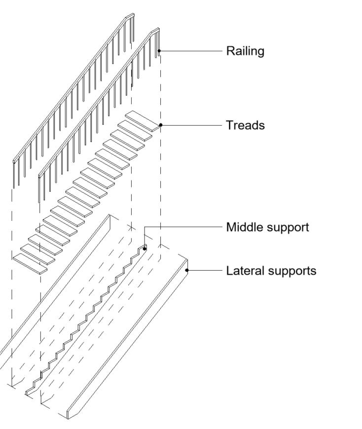
The stairs in a project usually get documented in four levels of information. These four levels follow different scales and formats and allow the reader to cross reference in between drawings for a better understanding of the vertical transportation in a project.
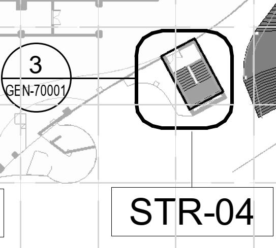
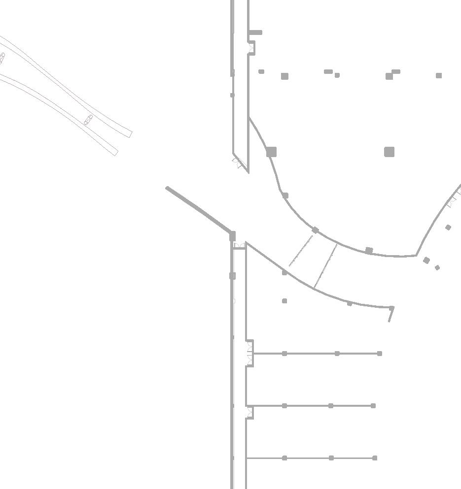
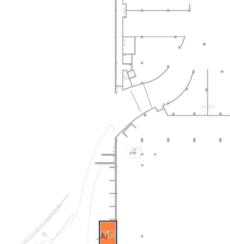
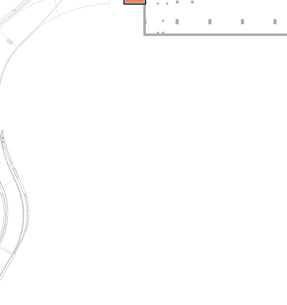
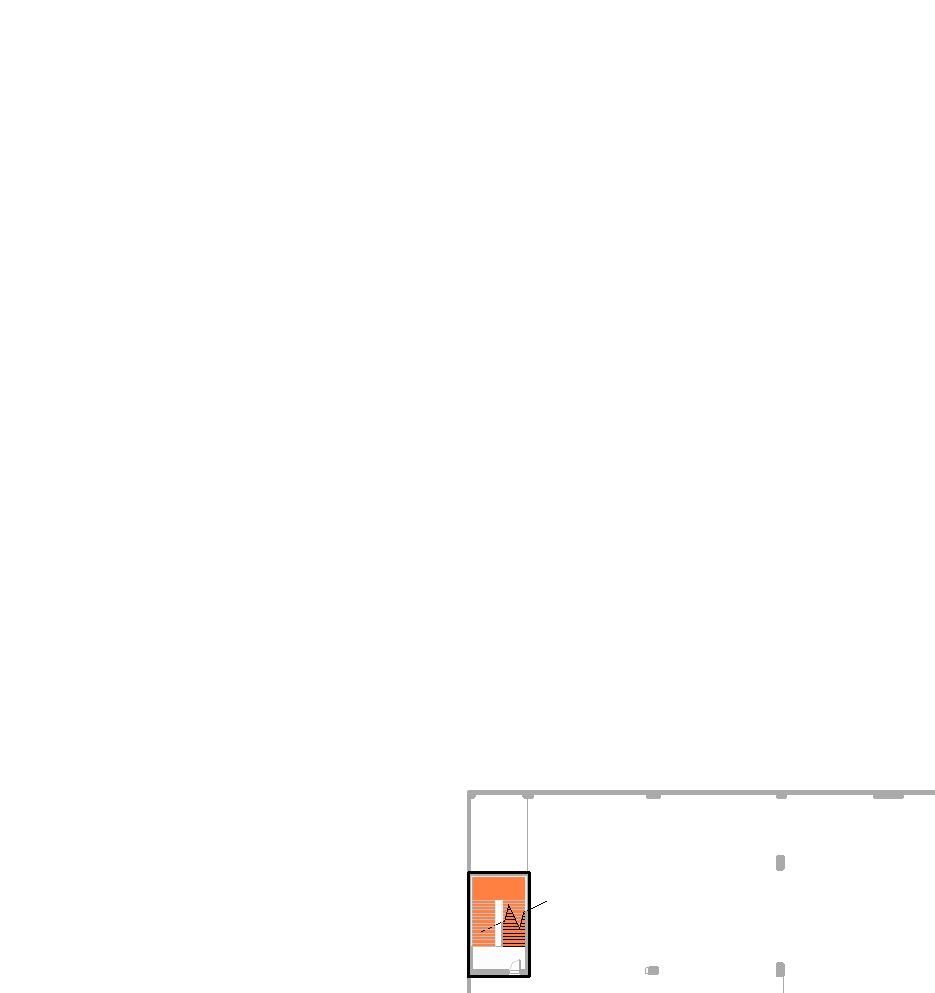
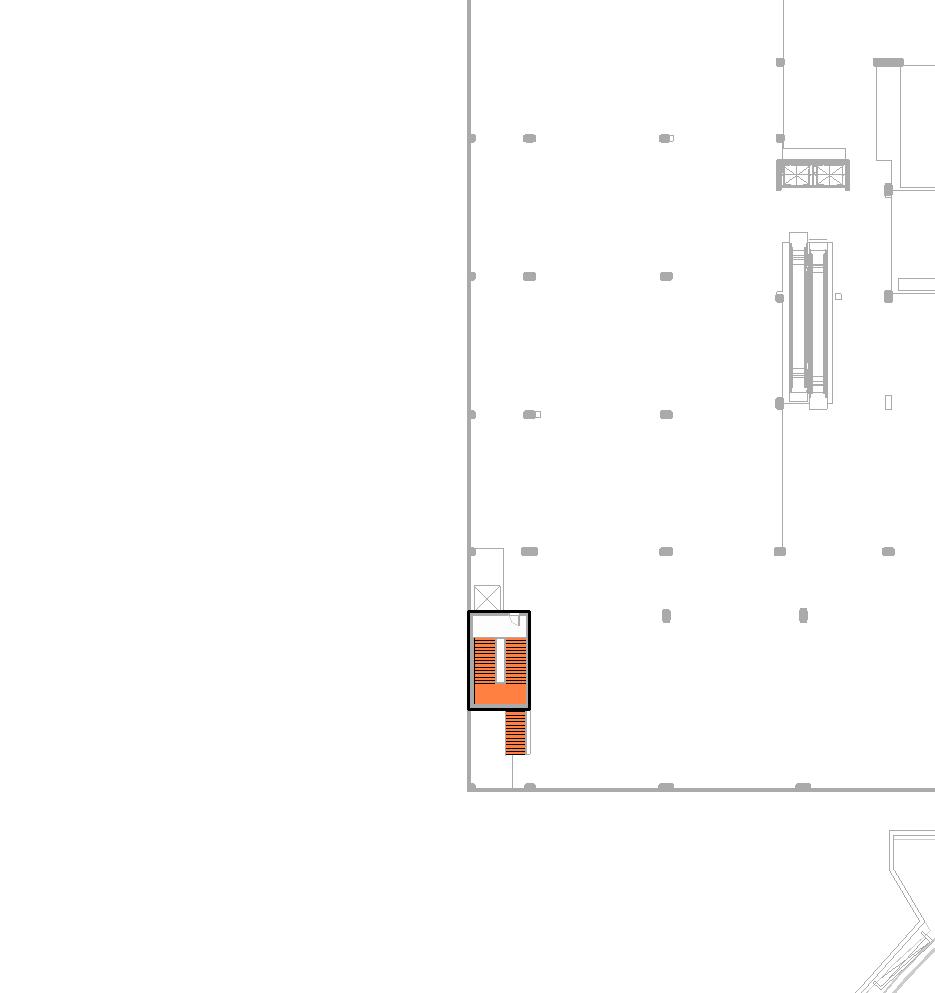
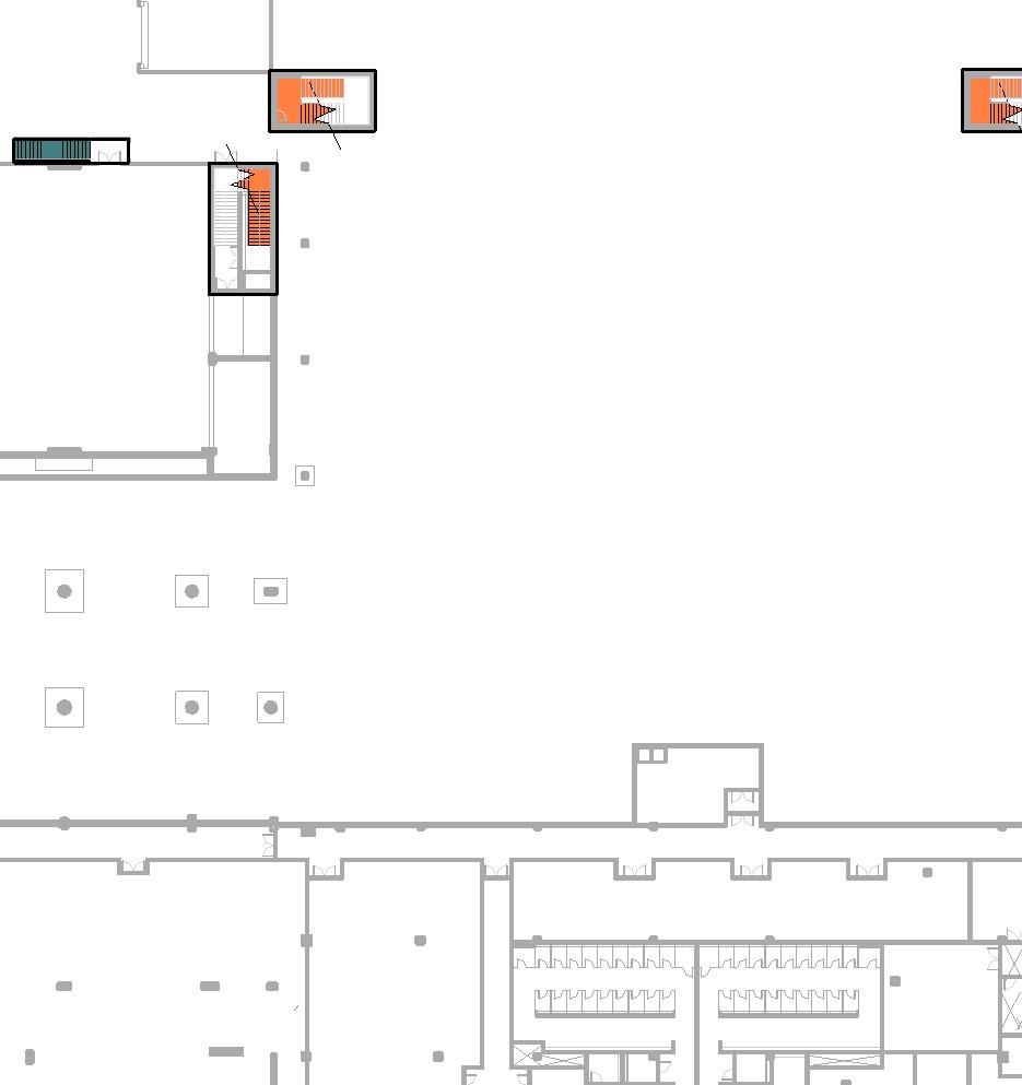
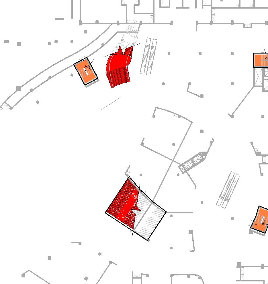
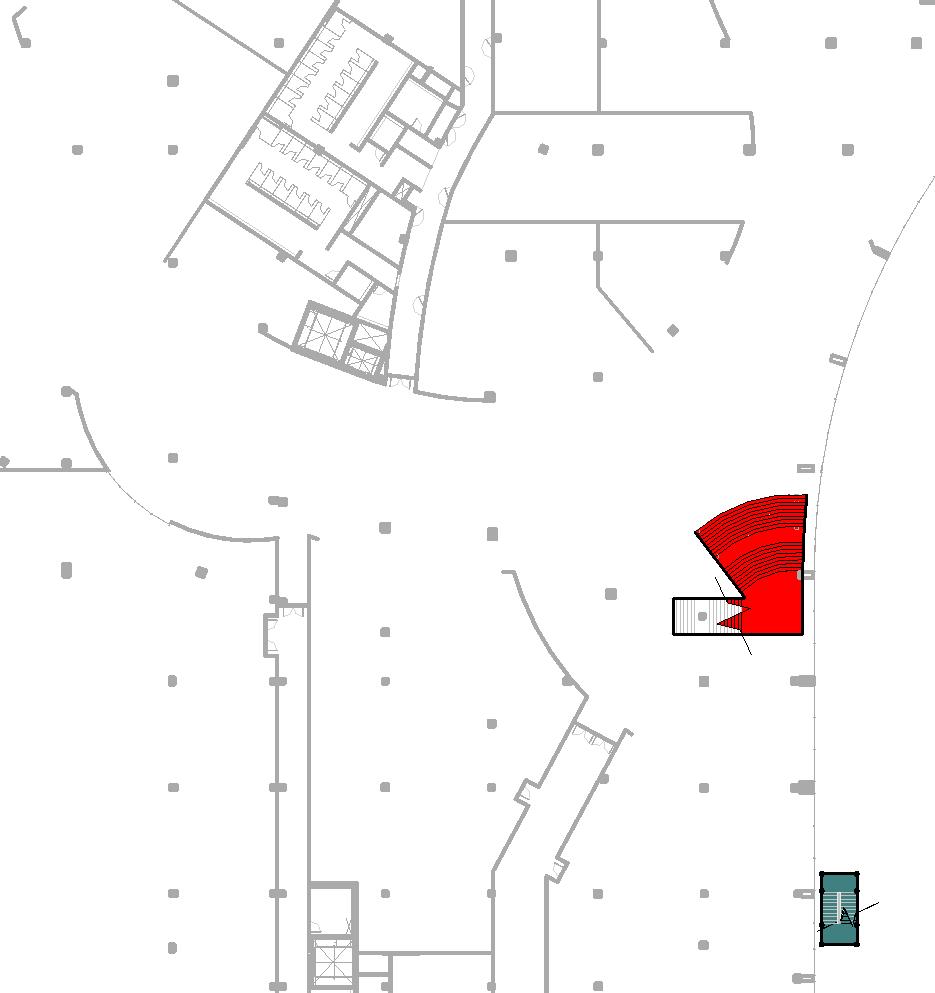
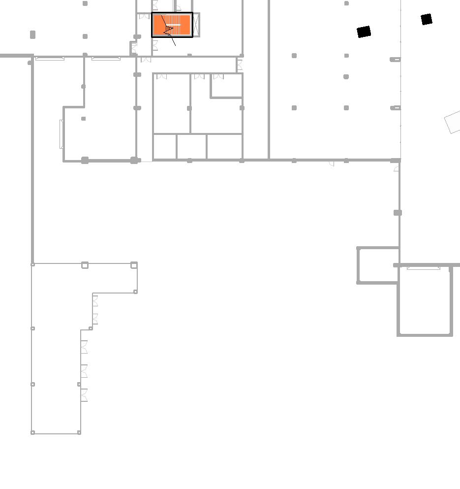
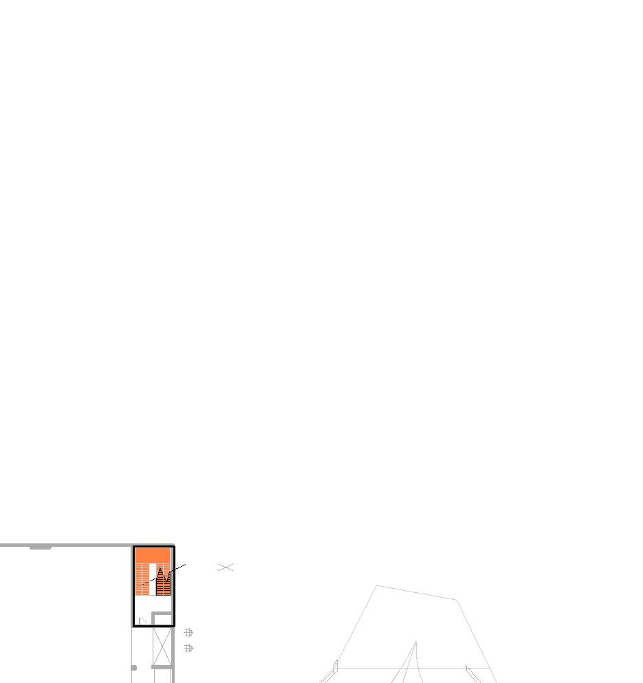
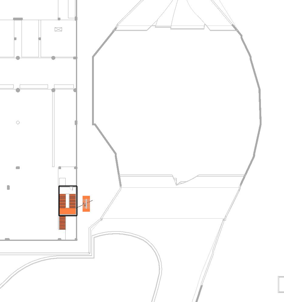
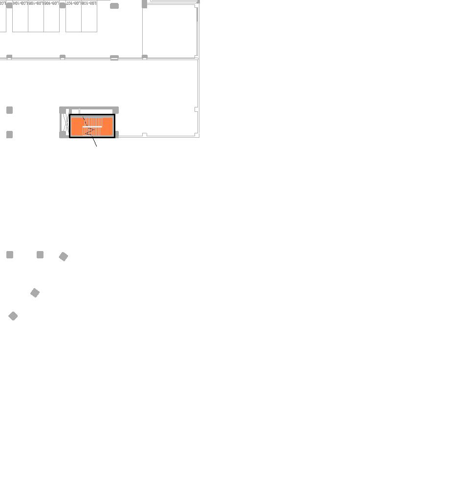
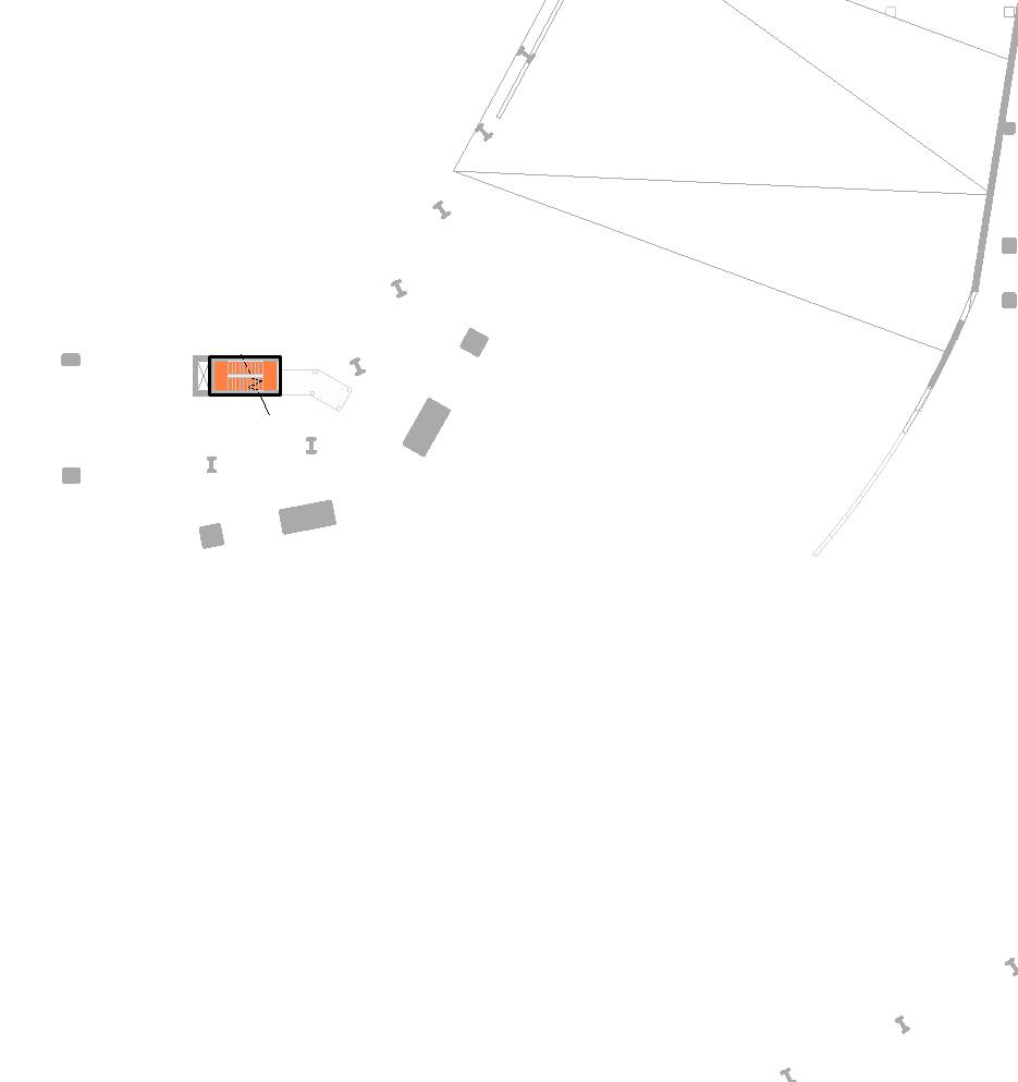
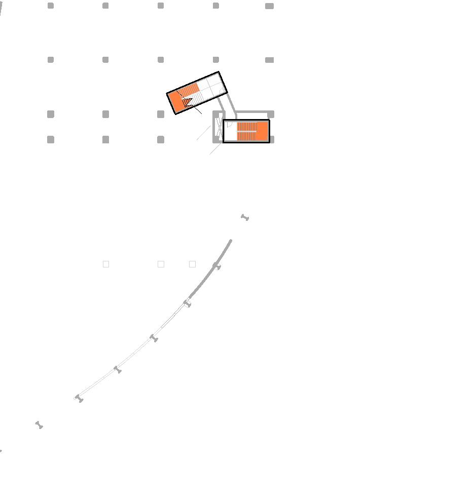
3.1 First level of information
floorplans and sections
scales 1:100 up to 1:1000 low detail
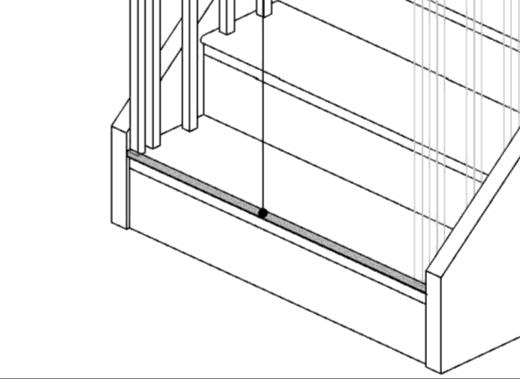
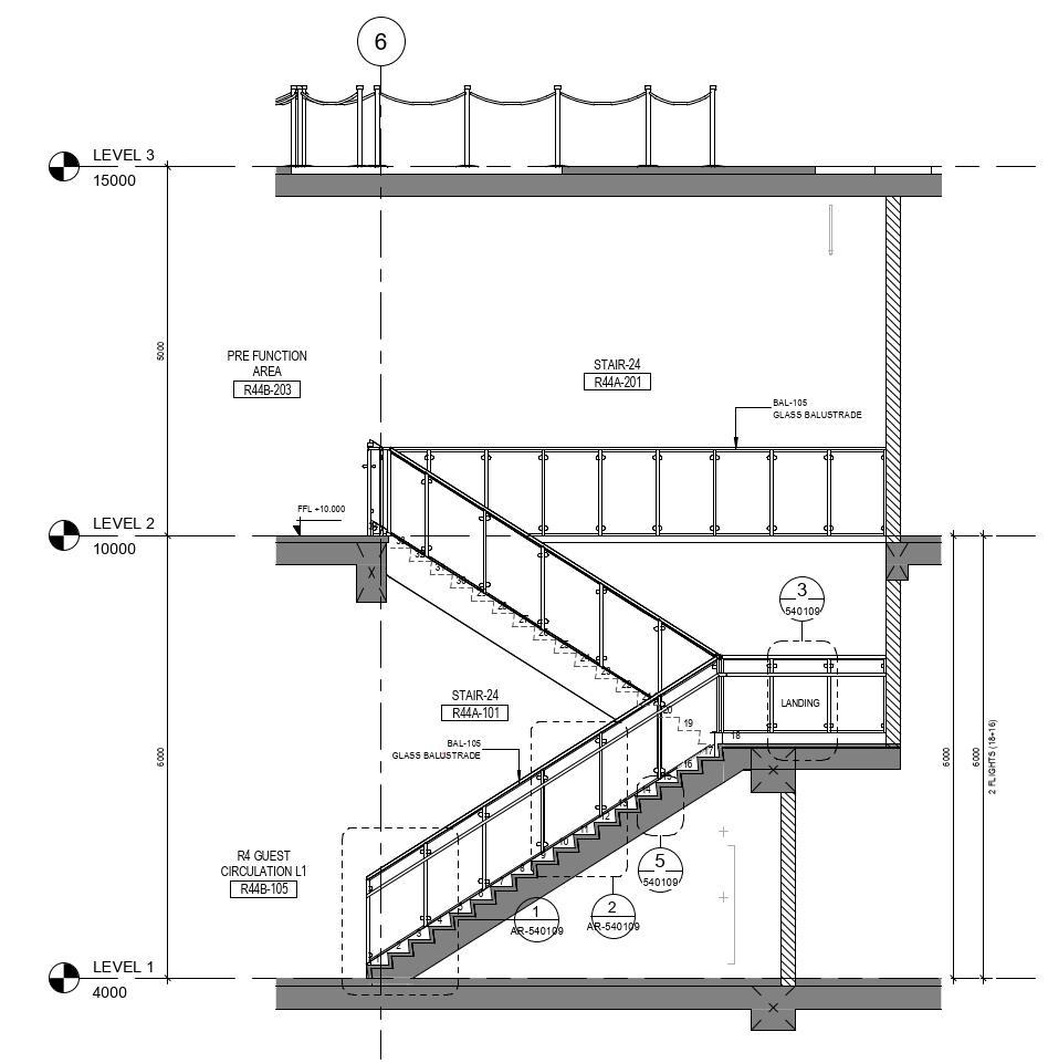
3.2 Second level of information
enlarged plans, sections and axonometric views
scales 1:50 up to 1:20 medium detail
Callouts help keep the bigger scale drawing clean and readable, while still providing a path to more detailed views Tags help connect elements in the drawings to a schedule, legend, or elsewhere in the construction documents
3.3 Third level of information
details in plan, section and elevation
scales 1:20 up to 1:1 maximum detail
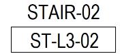
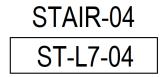
3.4 Fourth level of information stair schedule
How to codify a stair core for tagging:
Usually, a system that combines the starting level of the stair, it’s location in the arrangement on the plan, and an additional ordering number take place into setting up a code of tagging the stair core in plan and section. See examples below:


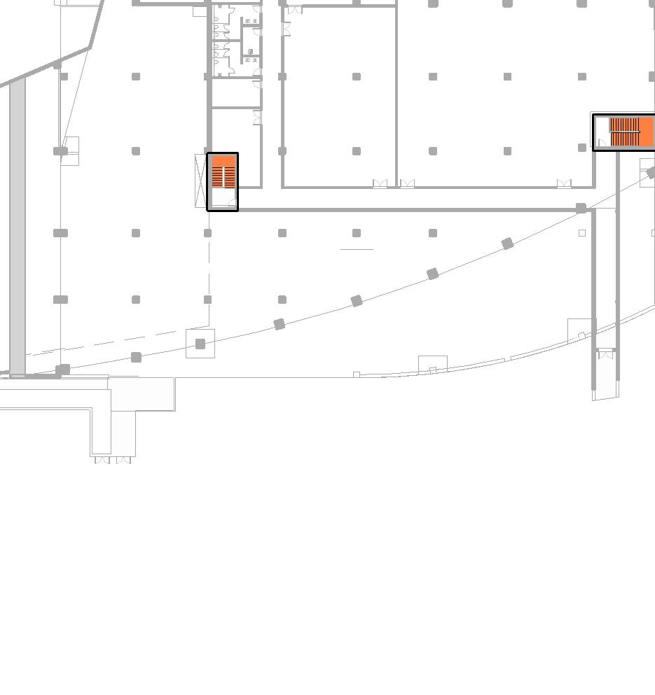
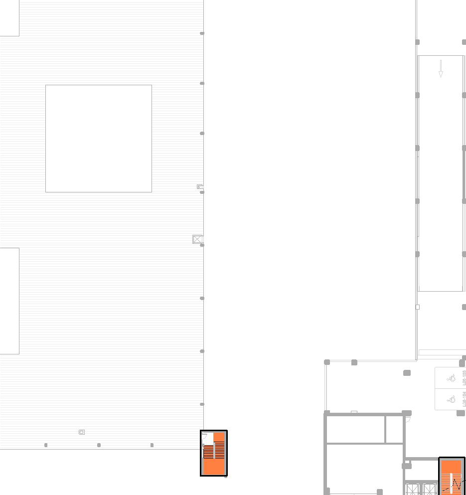
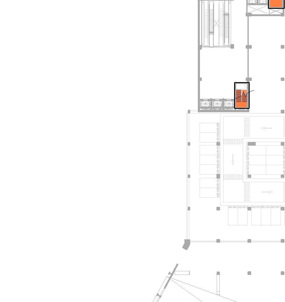
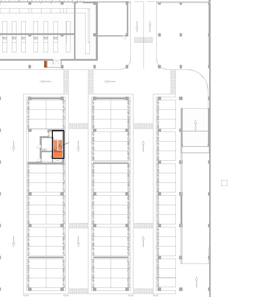
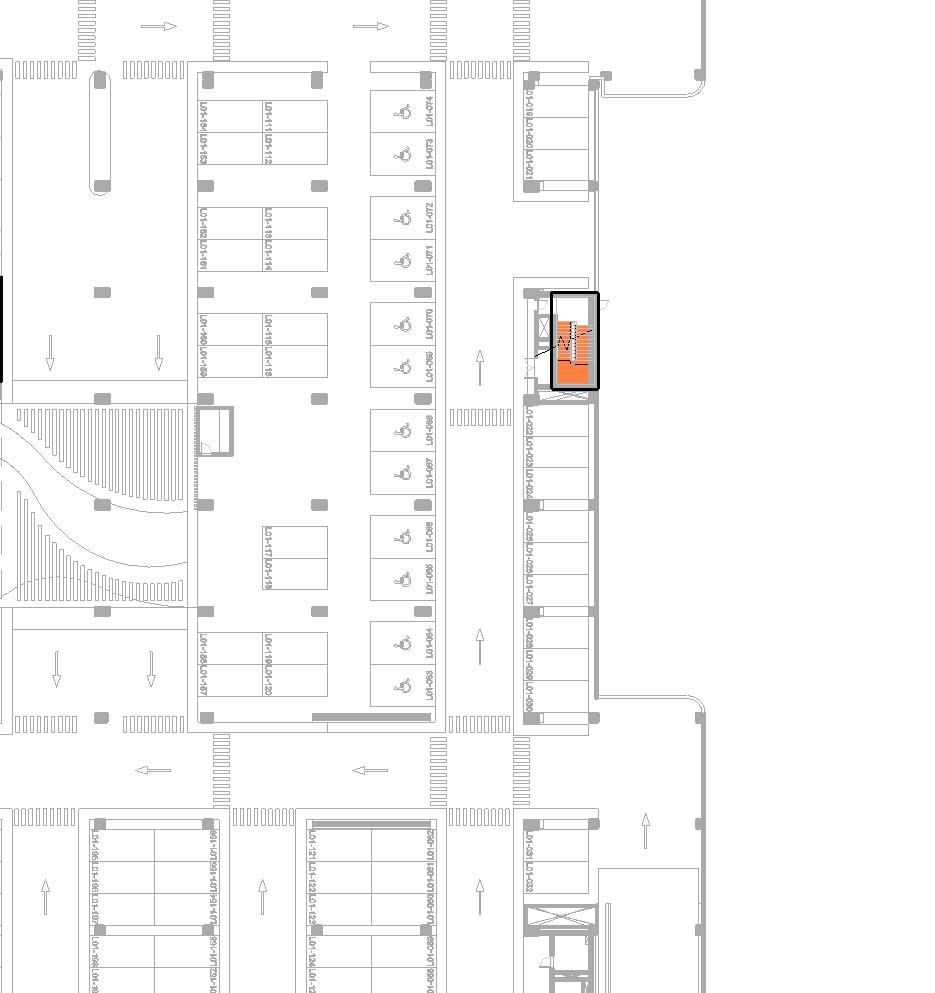
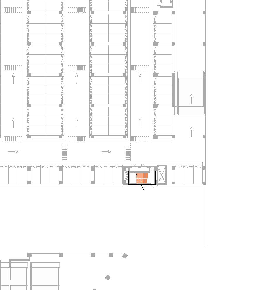
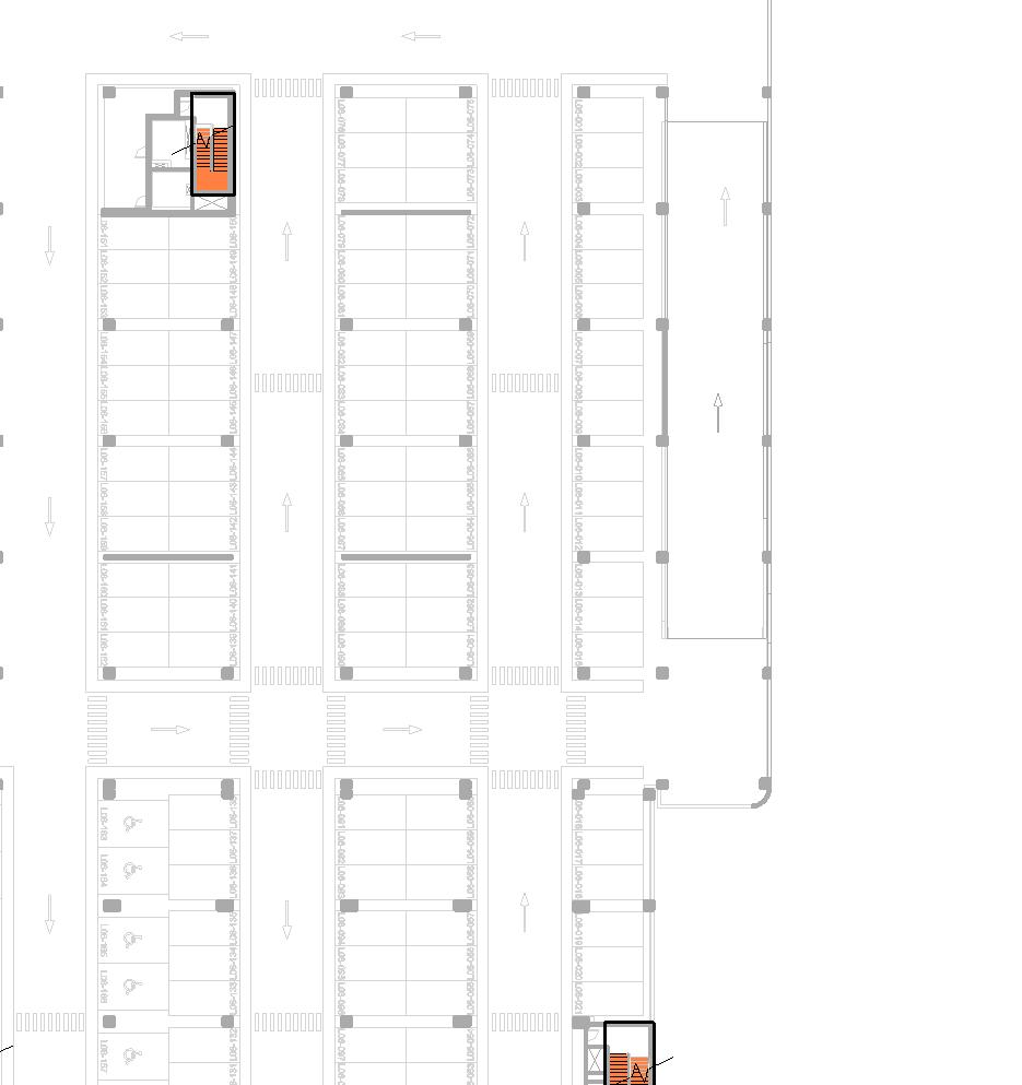
3.1 First level of information
how
to find the stairs in my project
• Purpose: identifying the stairs within the project
• Type of drawing: floorplans and sections
• Usual scales: from 1:100 up to 1:1000
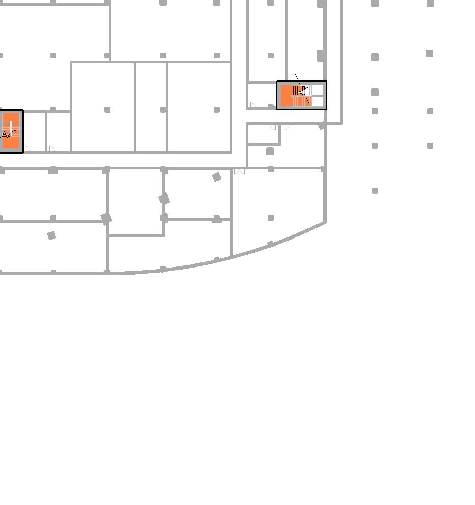
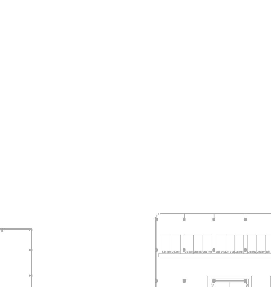
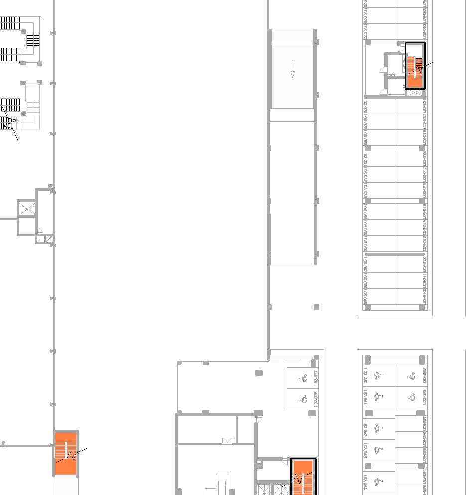
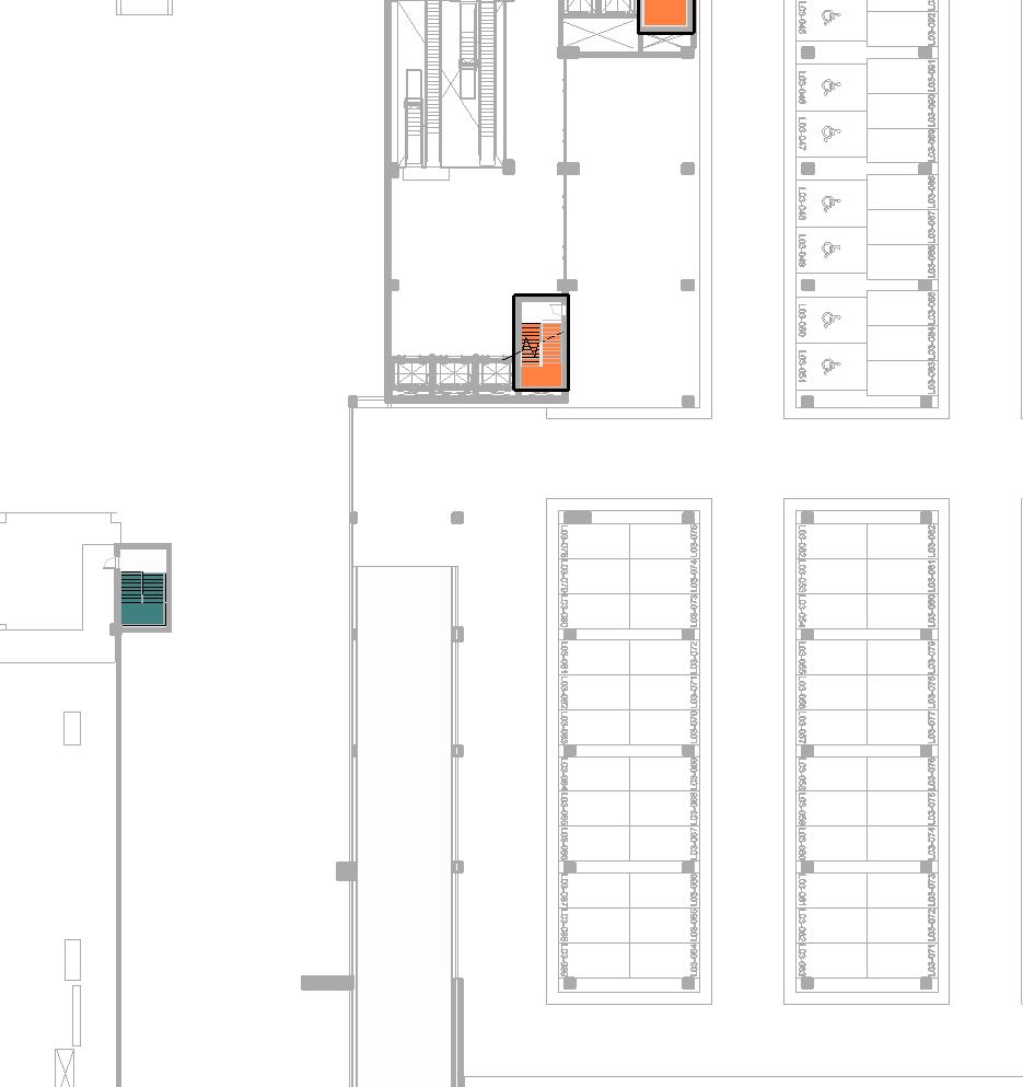
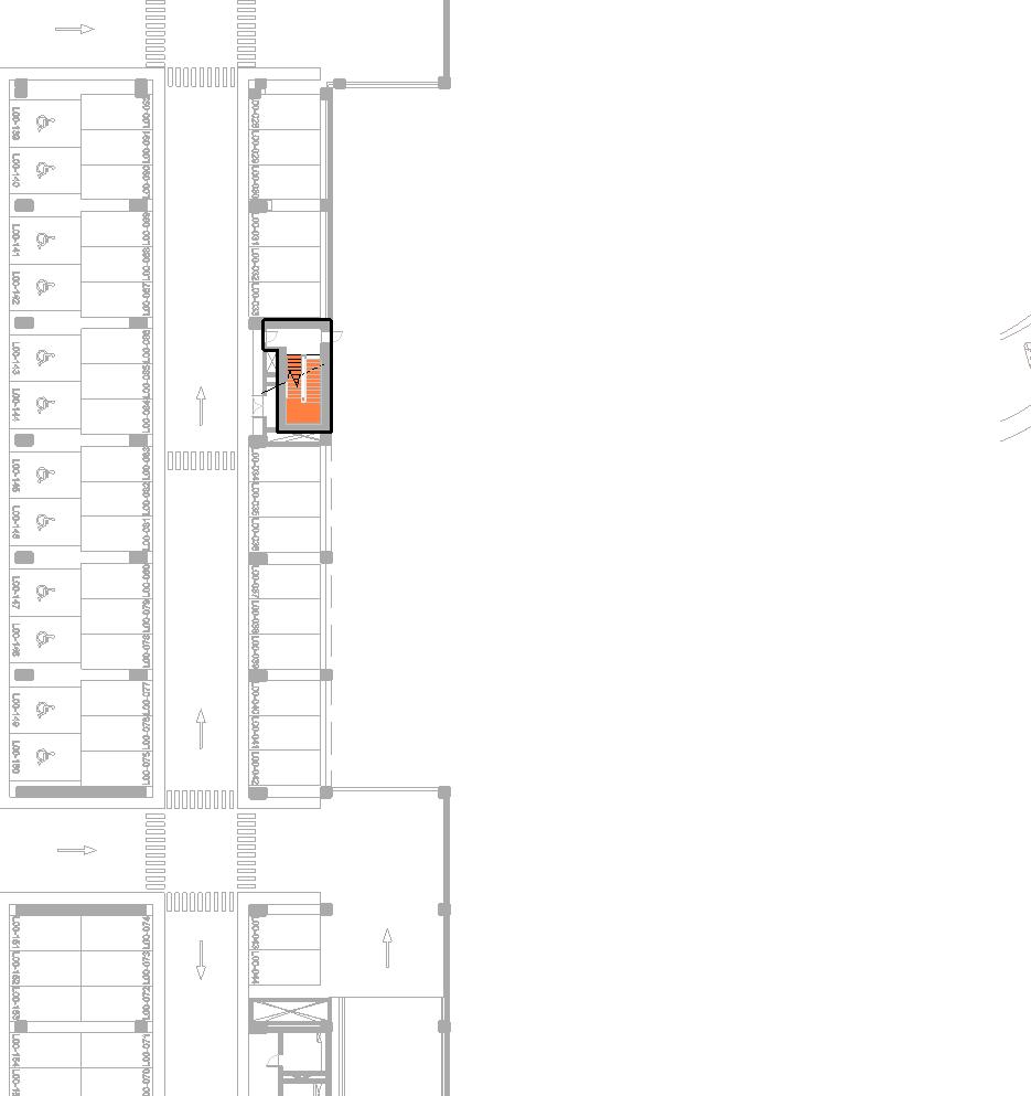
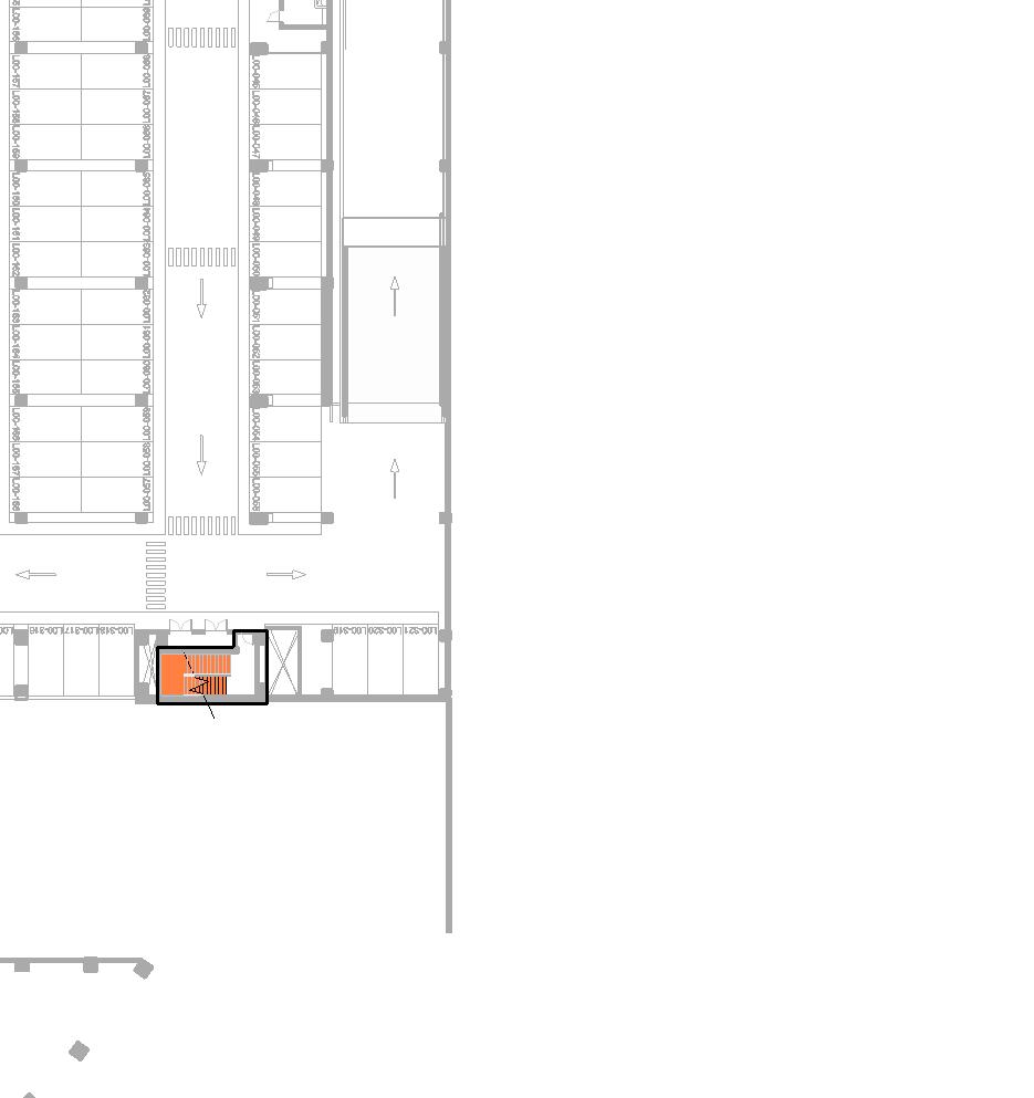
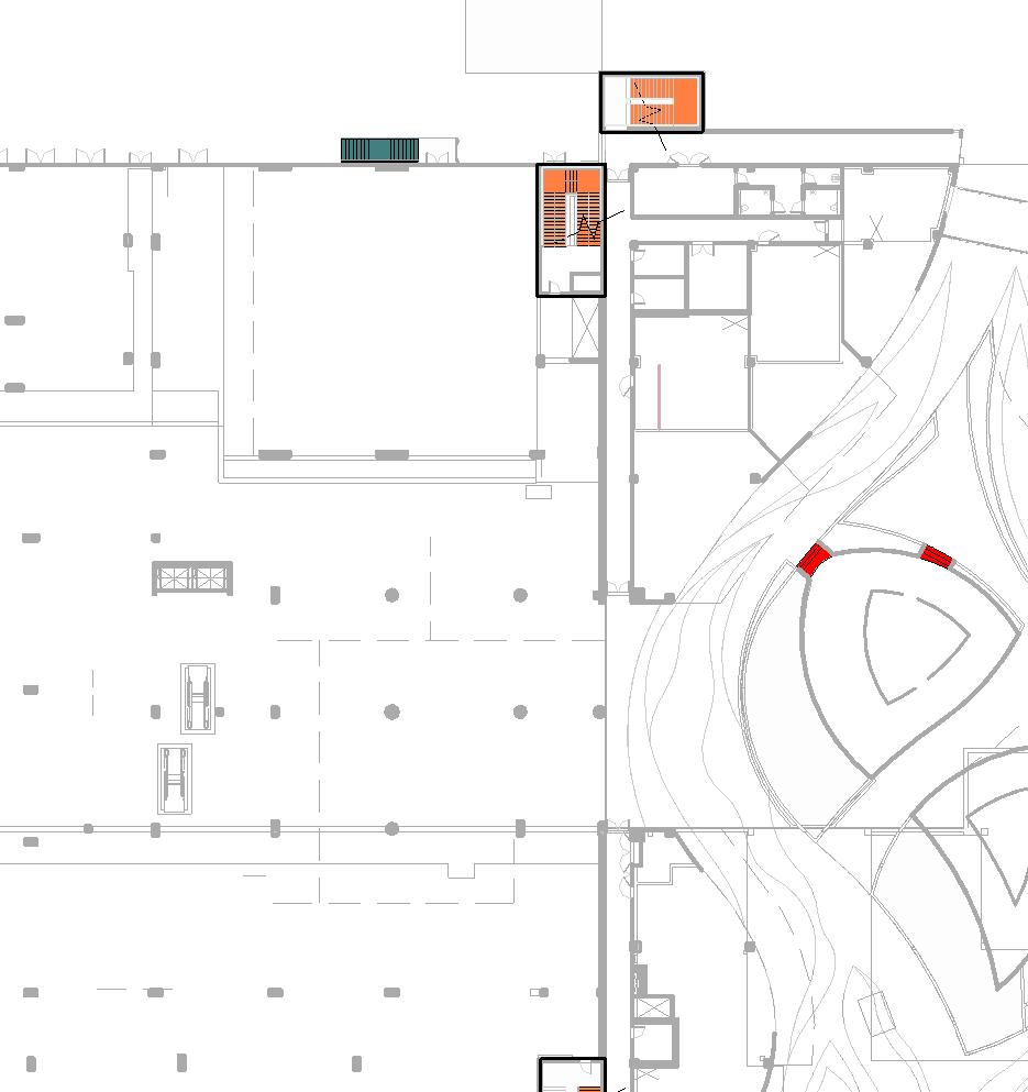
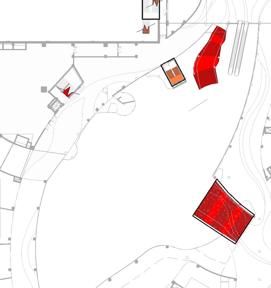
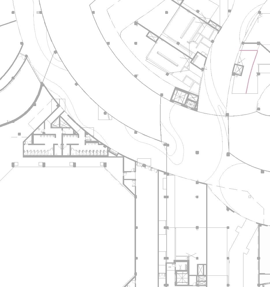
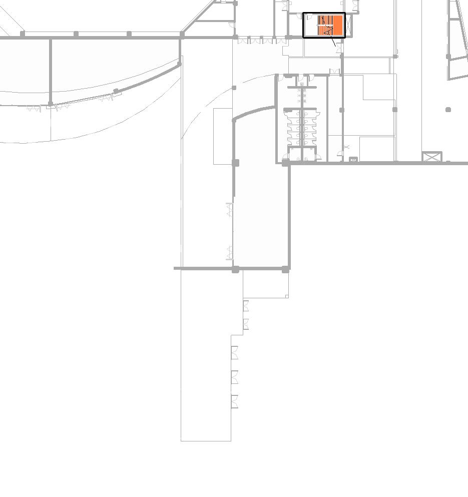
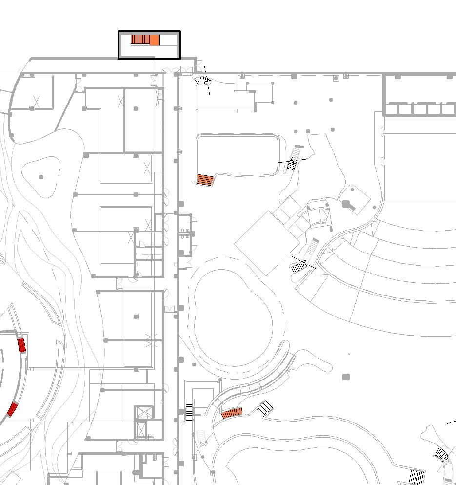
• Level of detailing: low (tags and some basic dimensions, callouts referencing a different scale) – stairs are tagged and called out, which take us to the second level of information
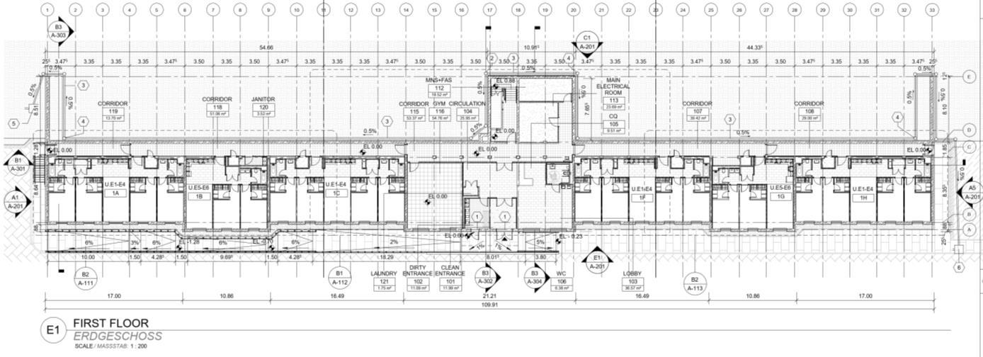
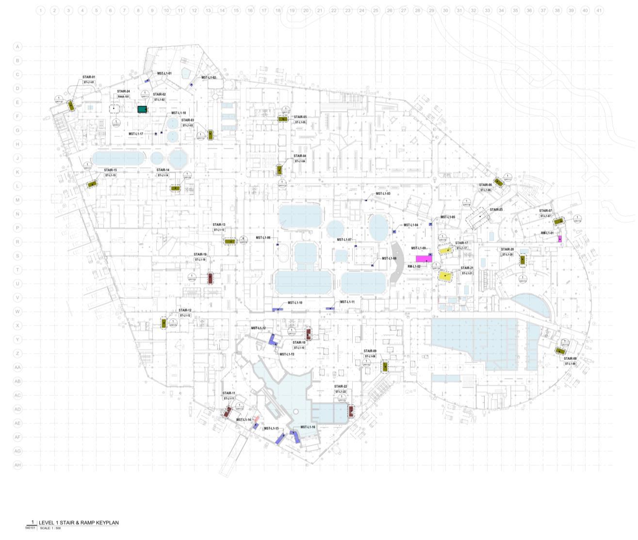
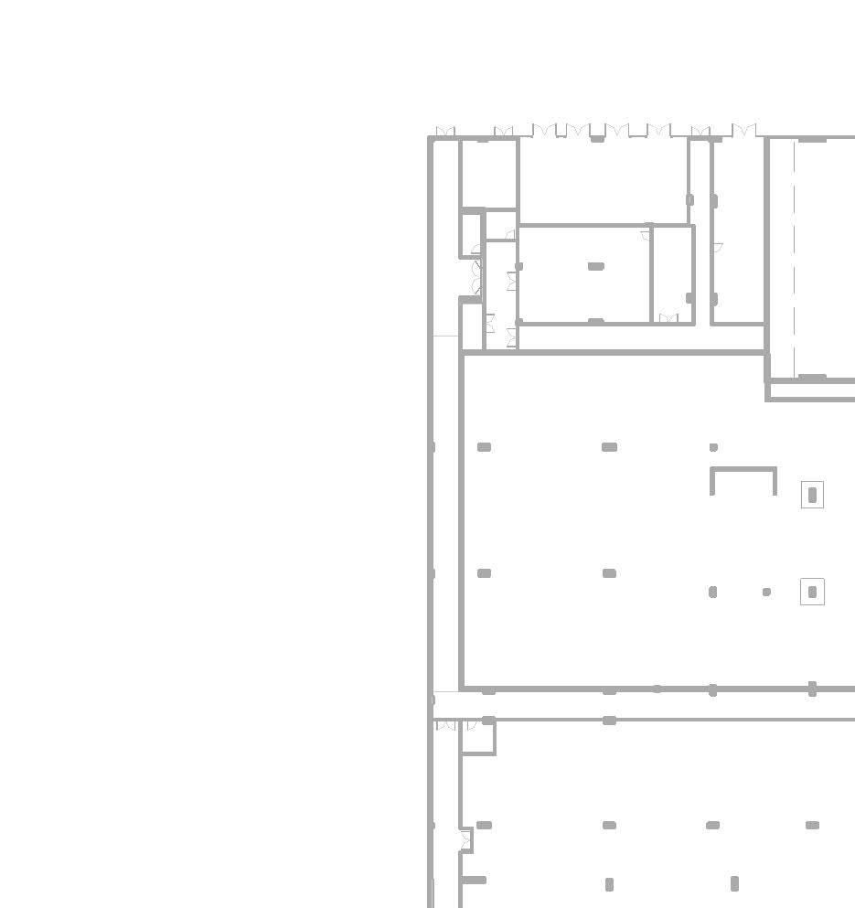
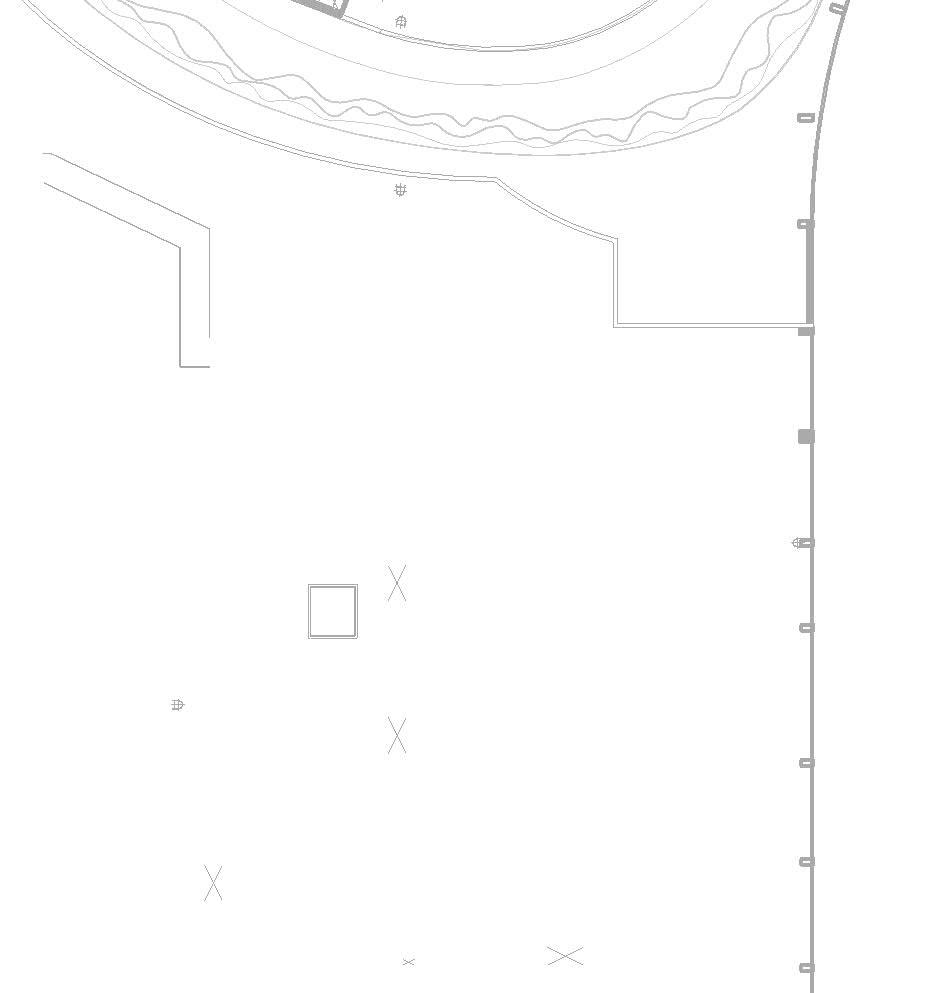
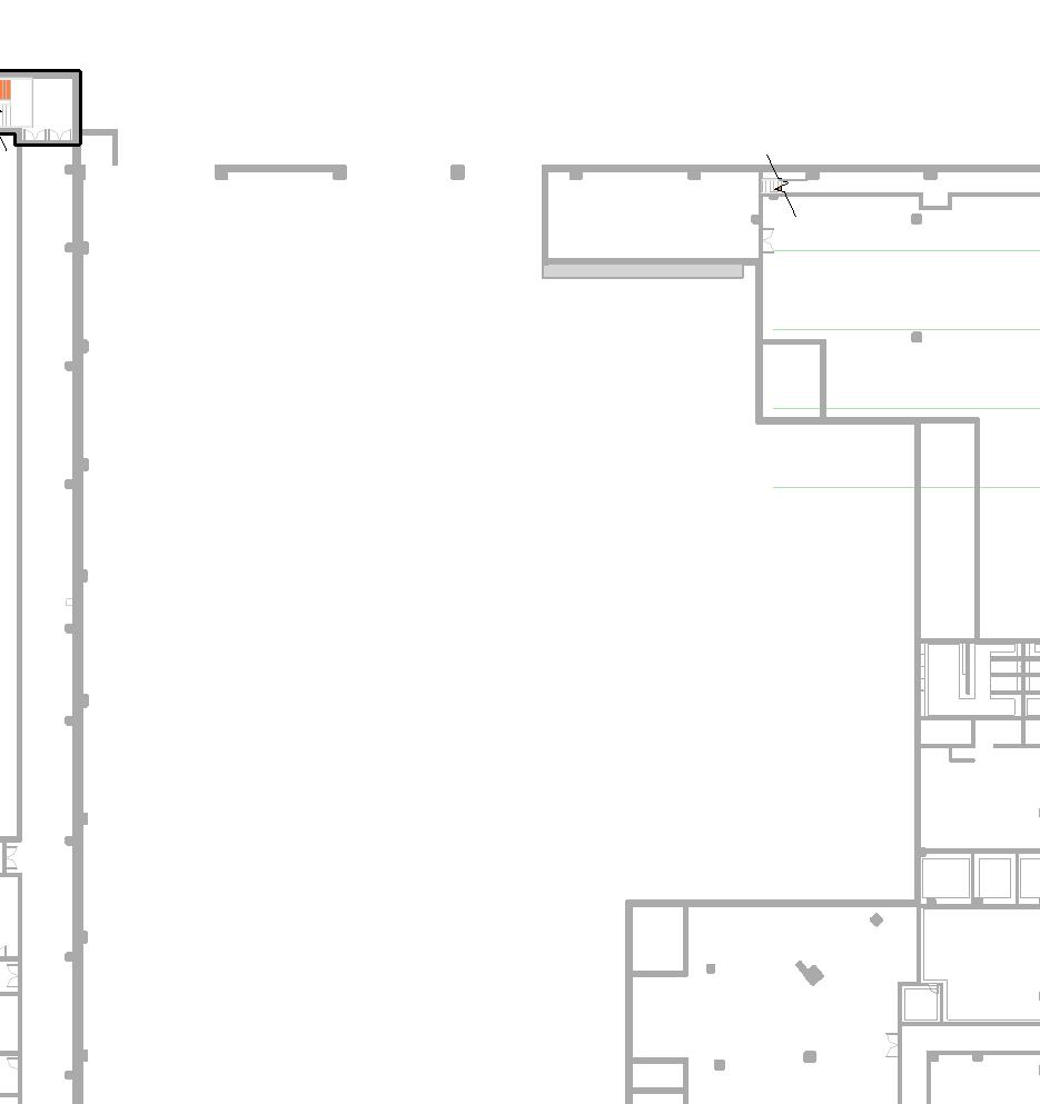
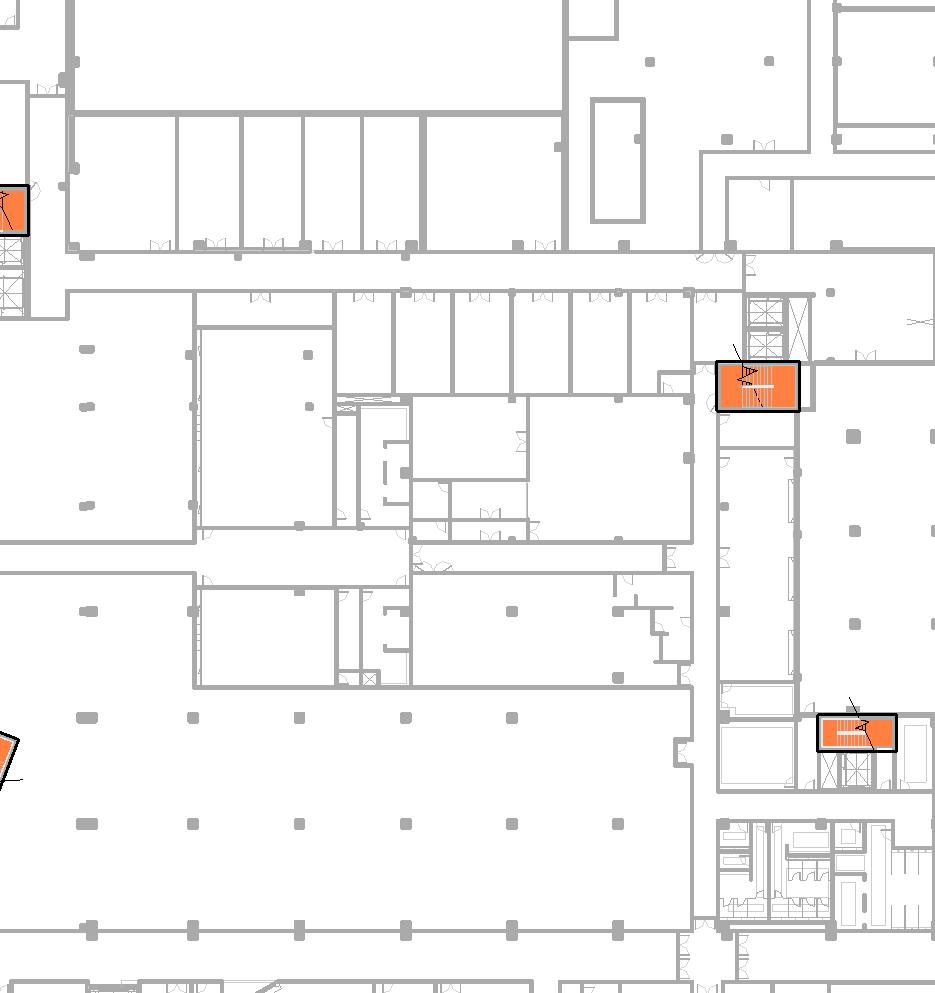
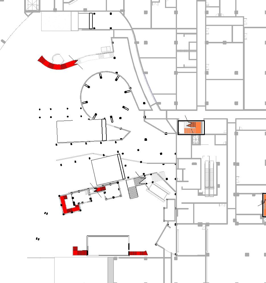
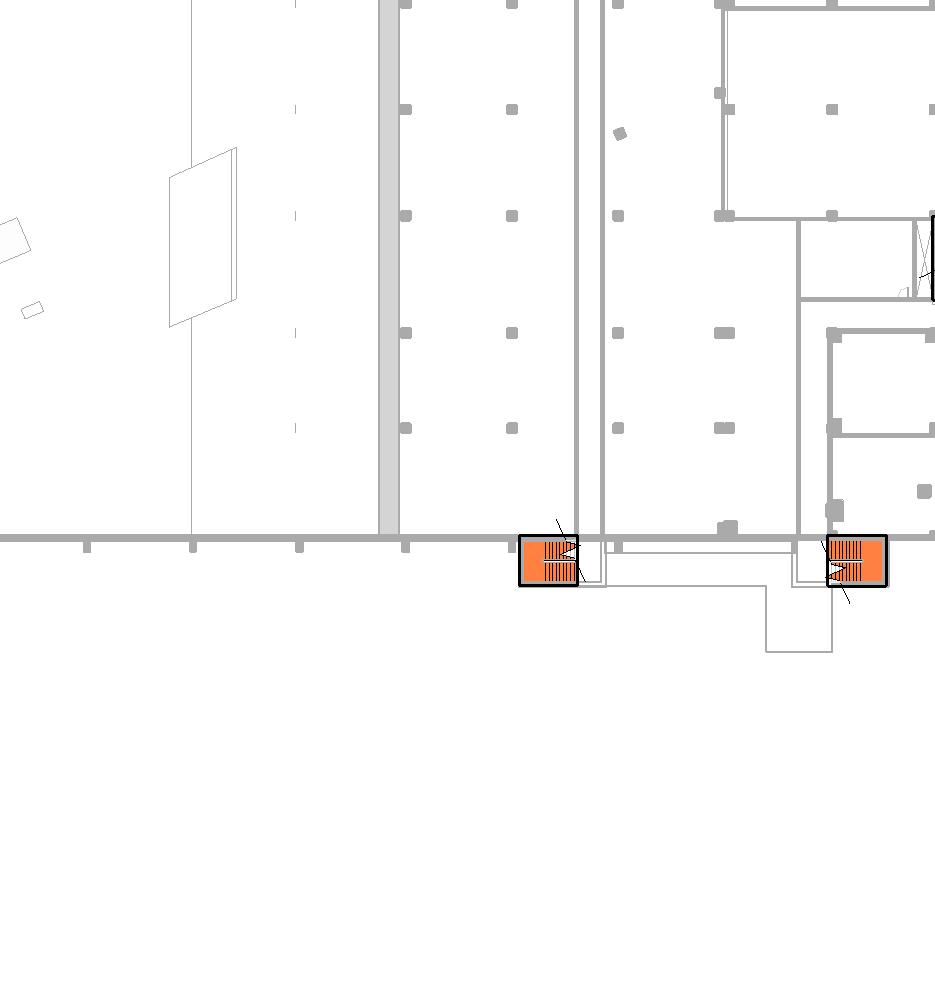
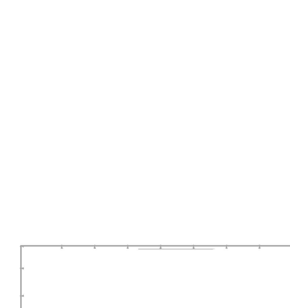
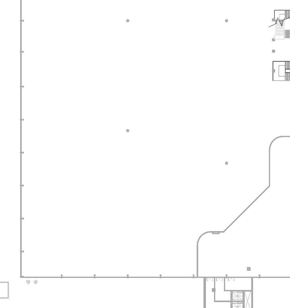
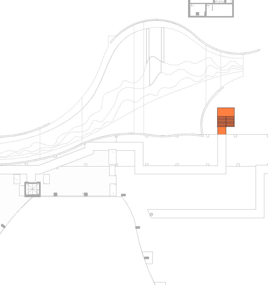
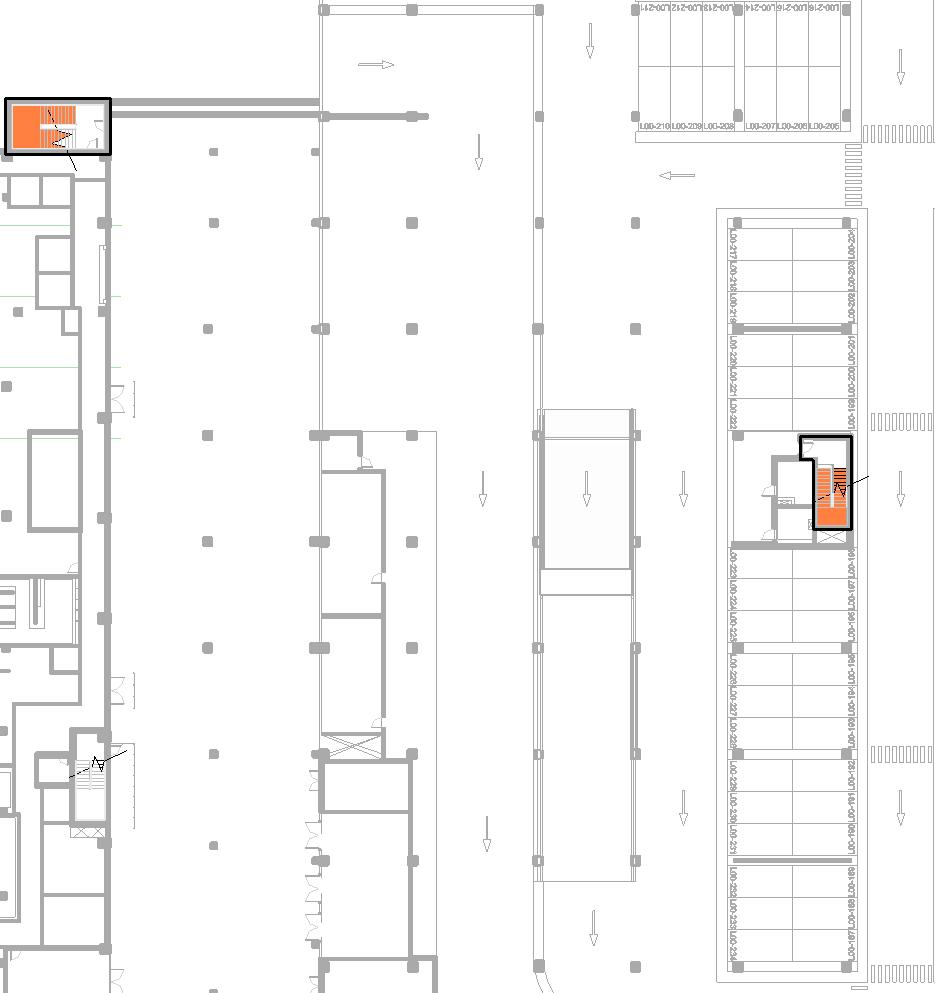
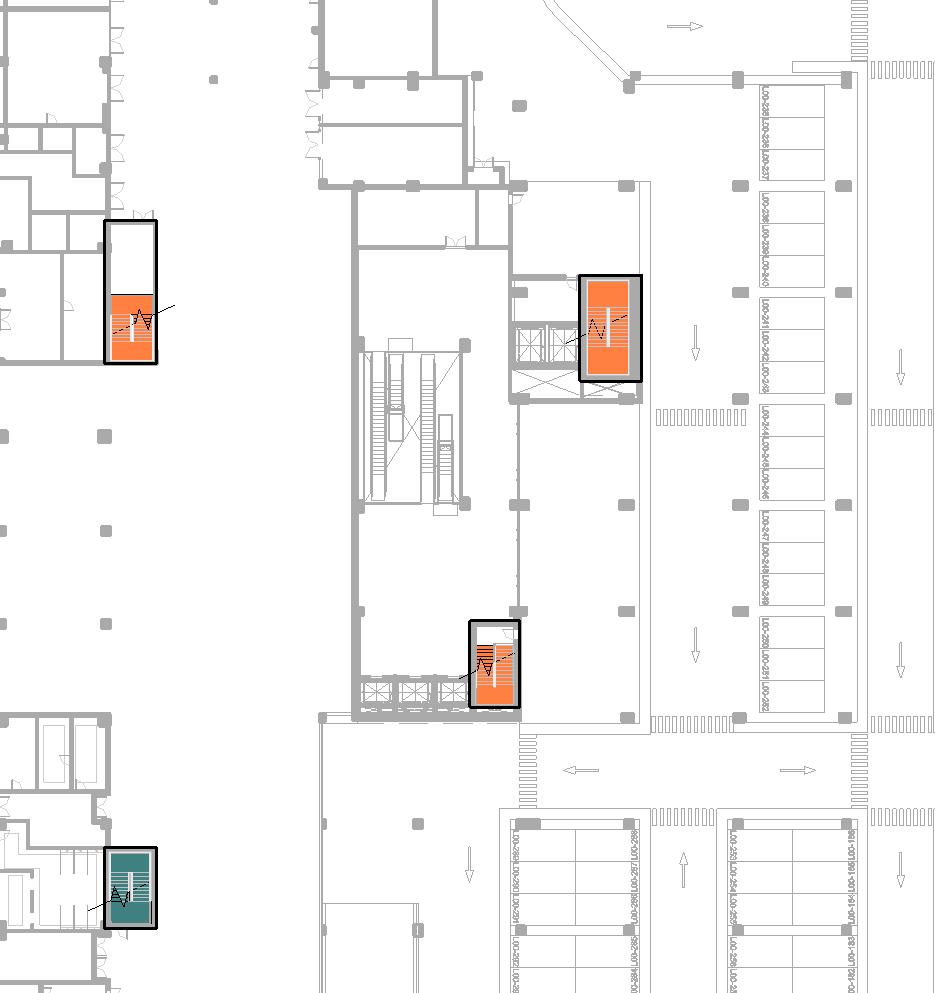
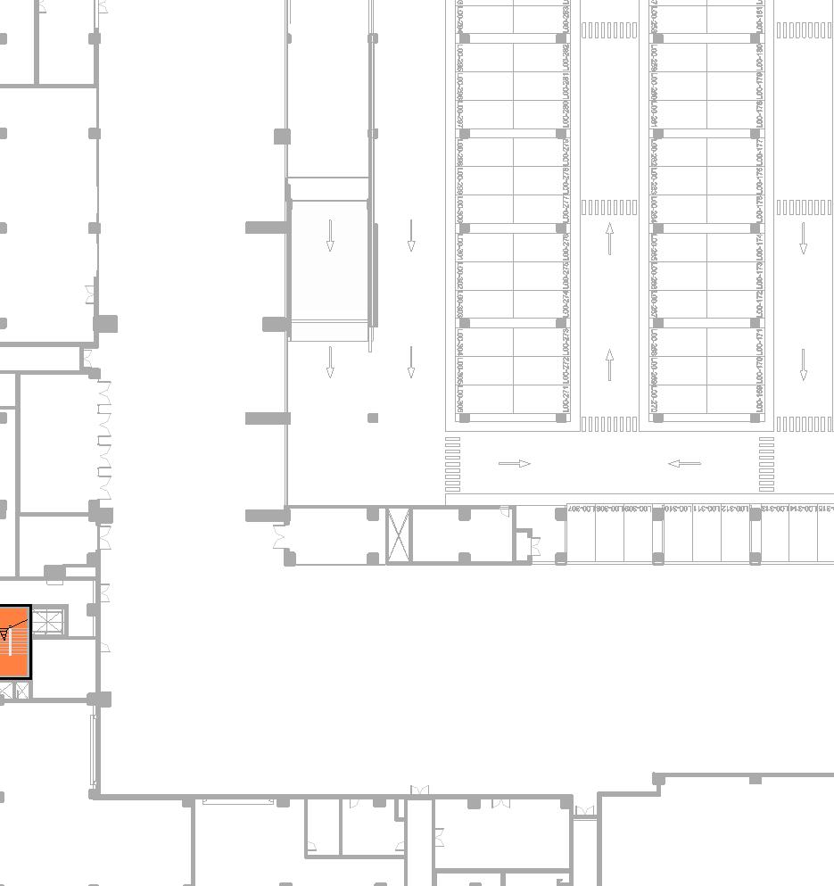
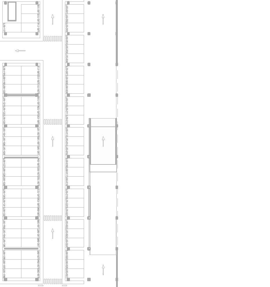
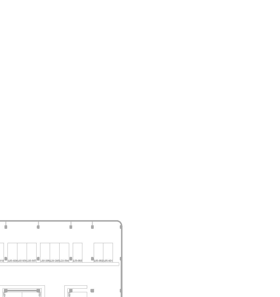
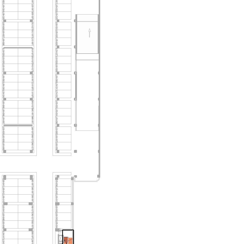
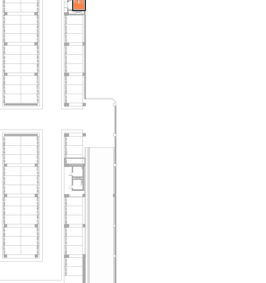
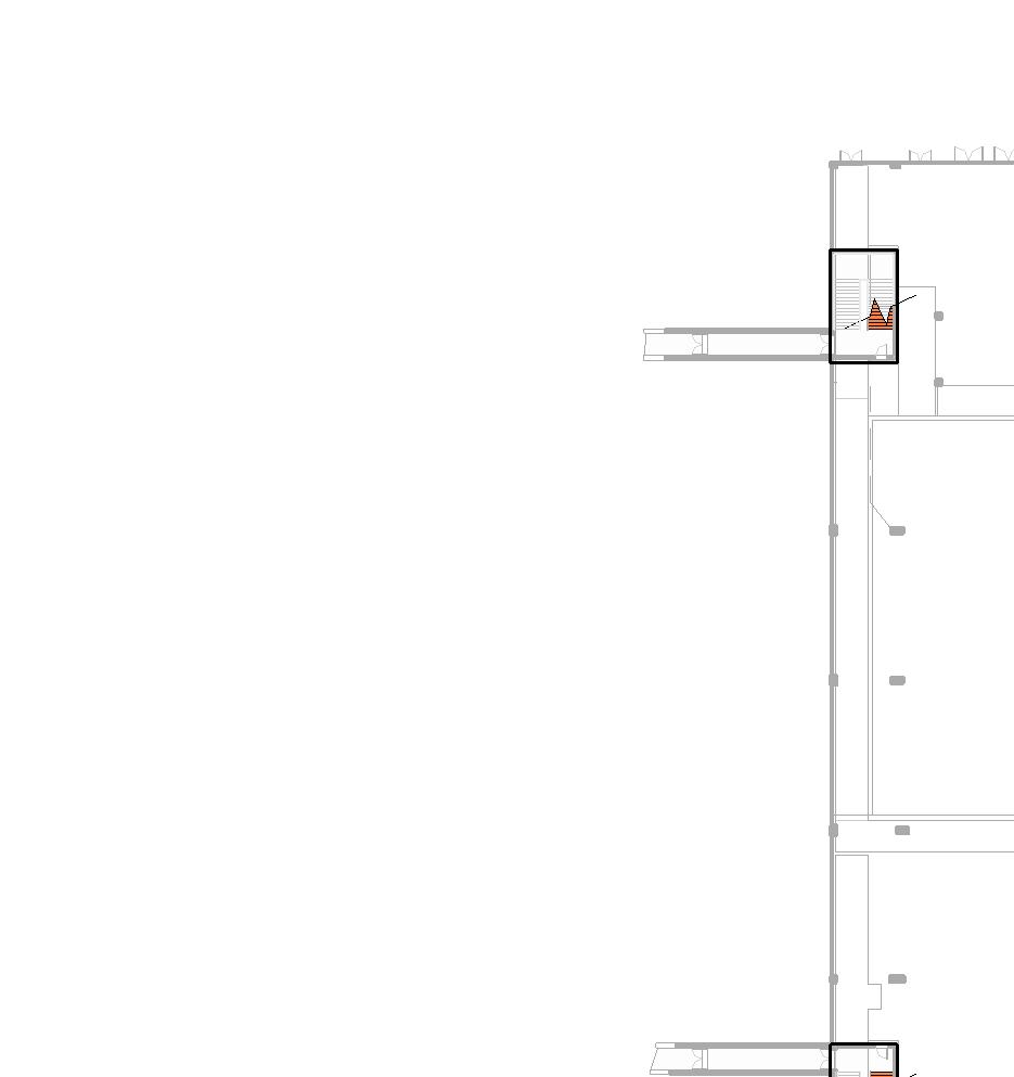
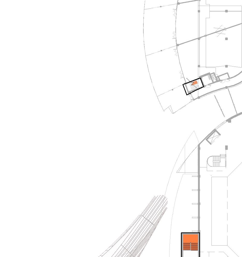
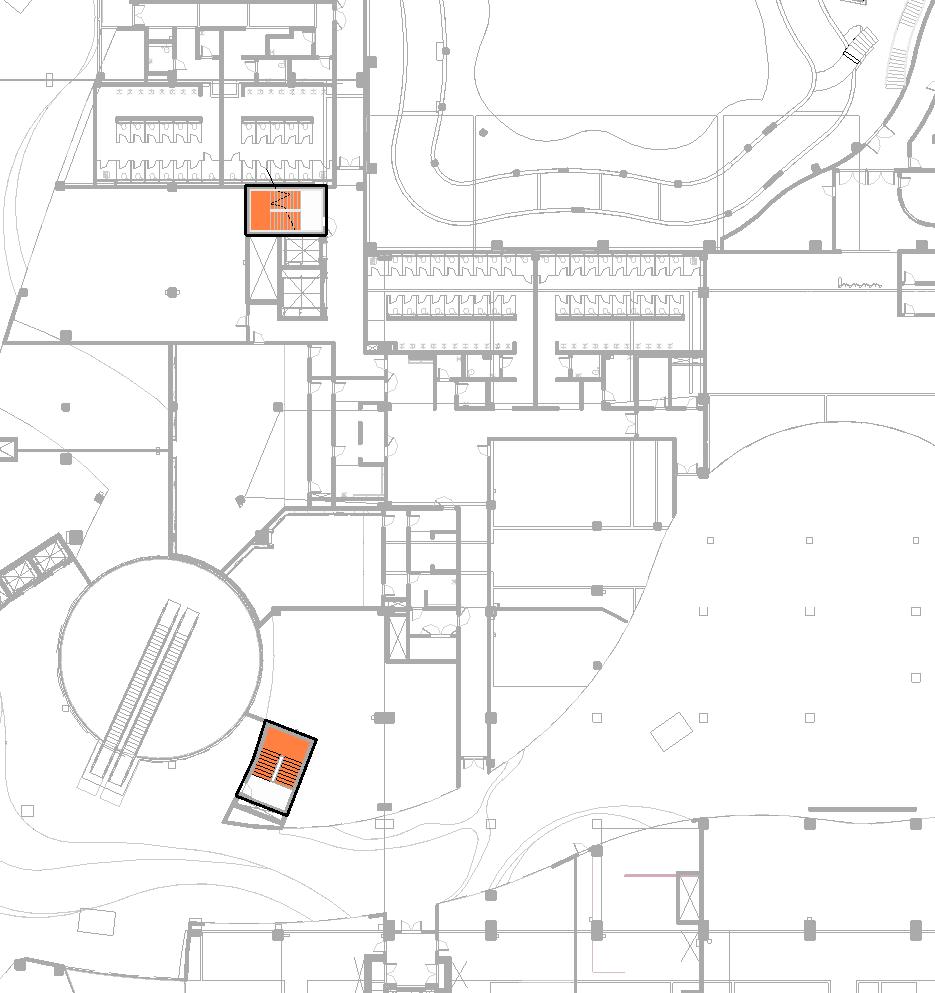
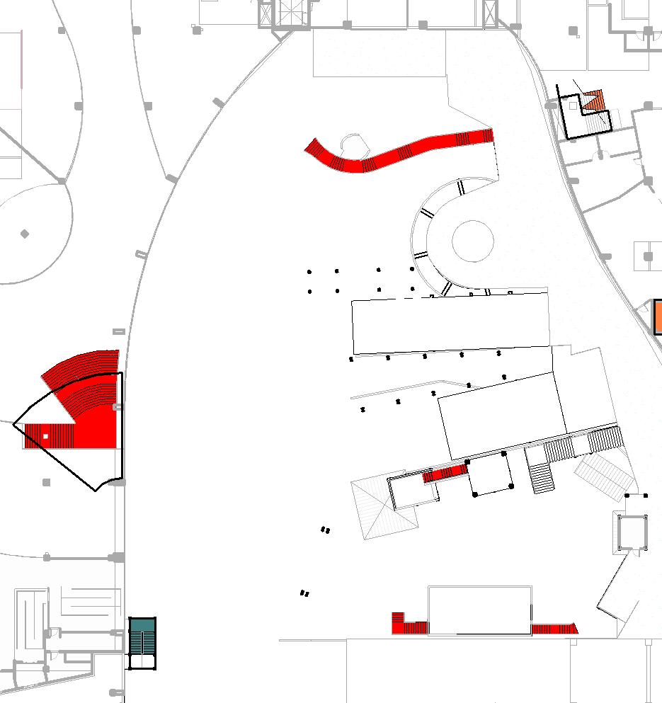
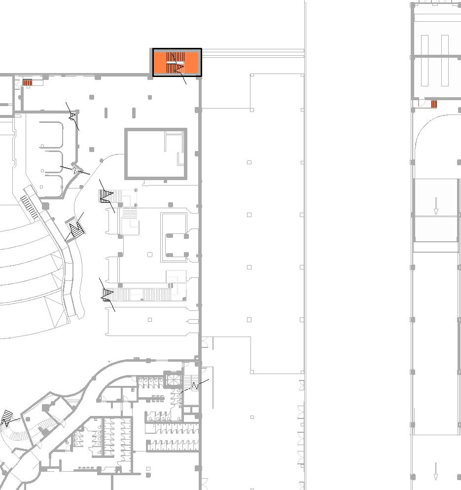
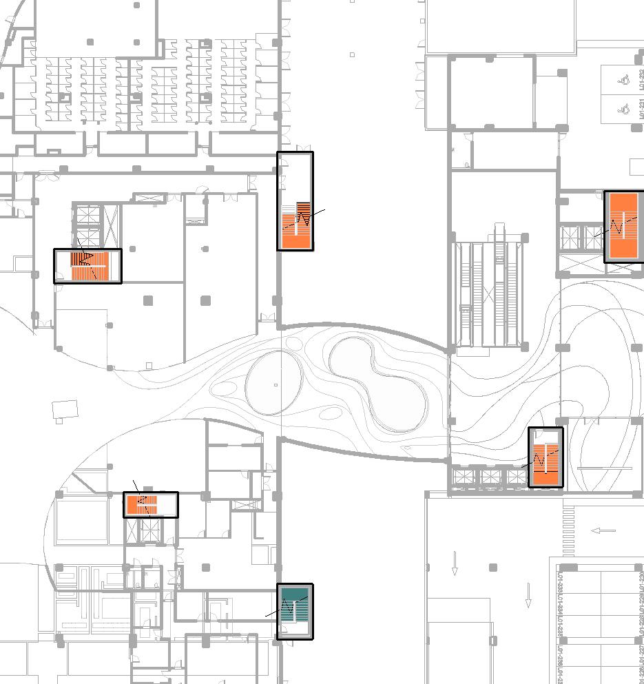
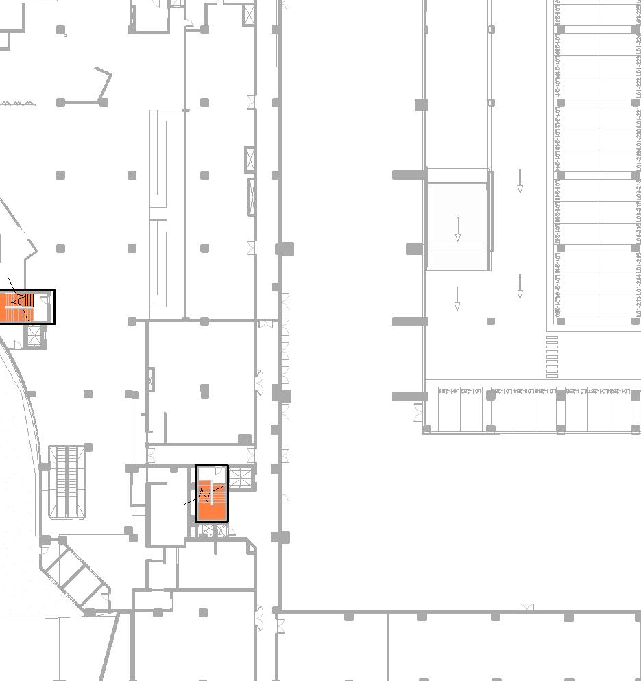
Floor plans at 1:500 and 1:200 * Find these examples’ full documentation in chapter 09
Chart how to find the stairs in my project
• Purpose: identifying the stairs within the project
• Type of drawing: floorplans and sections
• Usual scales: from 1:100 up to 1:1000
• Level of detailing: low (tags and some basic dimensions, callouts referencing a different scale) – stairs are tagged and called out, which take us to the second level of information
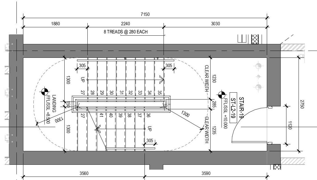
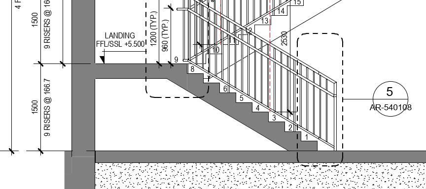
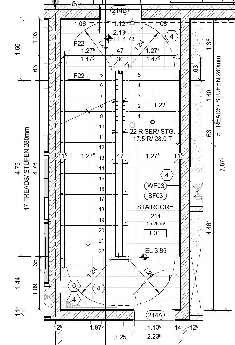
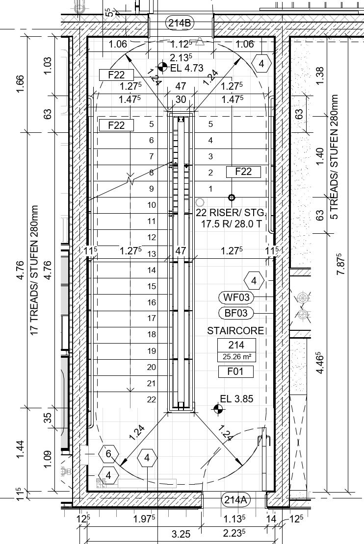
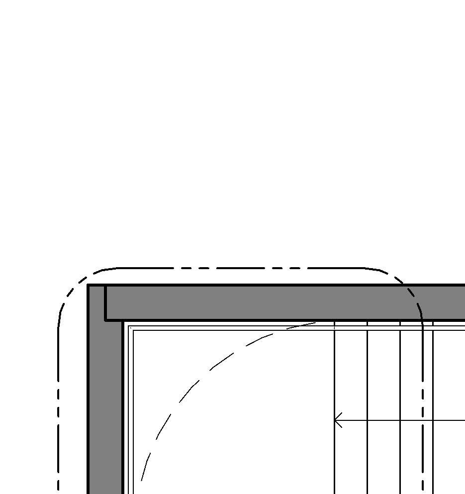
3.2 Second level of information
how to find the stairs in my project
• Purpose: detailing the dimensions, the different levels that the stair covers, and its components
• Type of drawing: enlarged plans, sections and axonometric views
• Usual scales: from 1:50 to 1:20
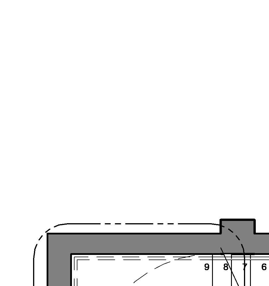
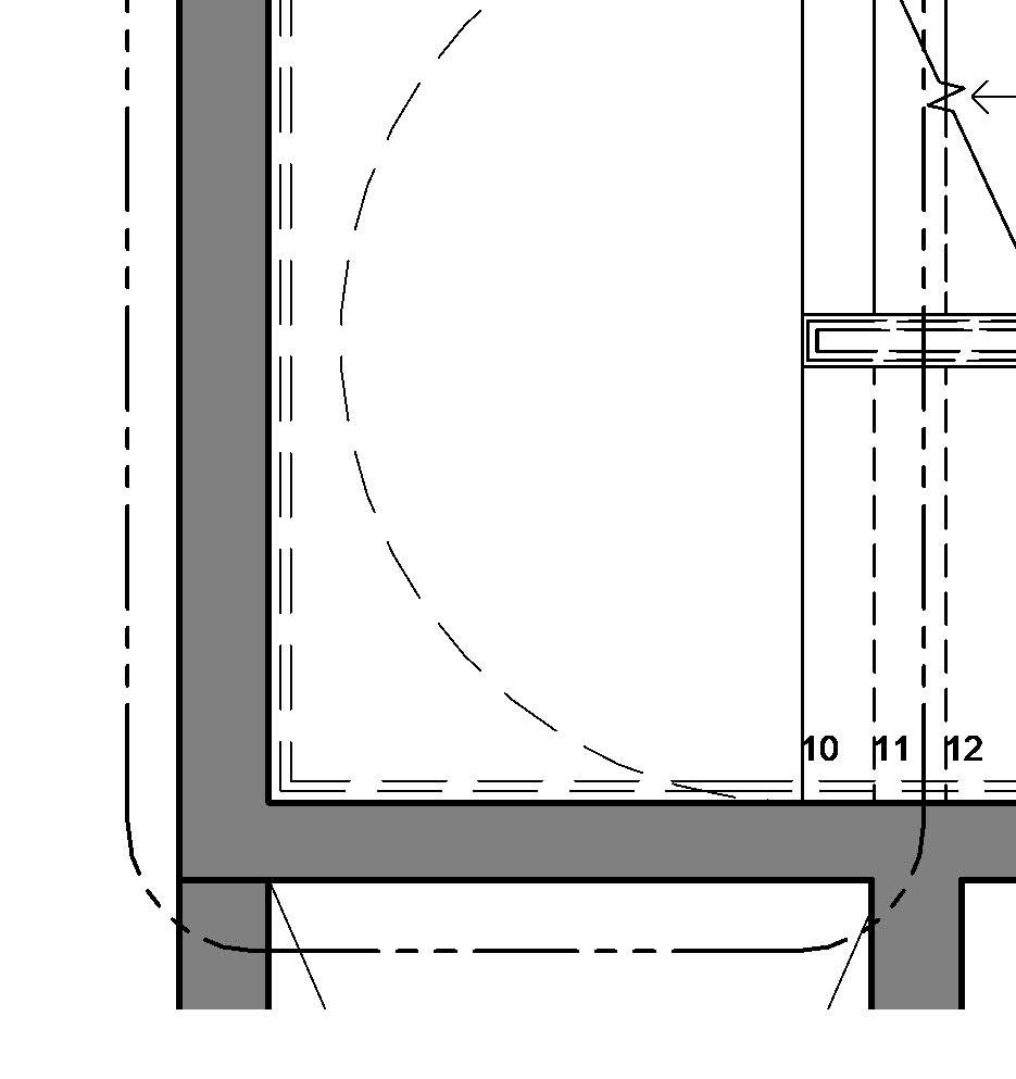
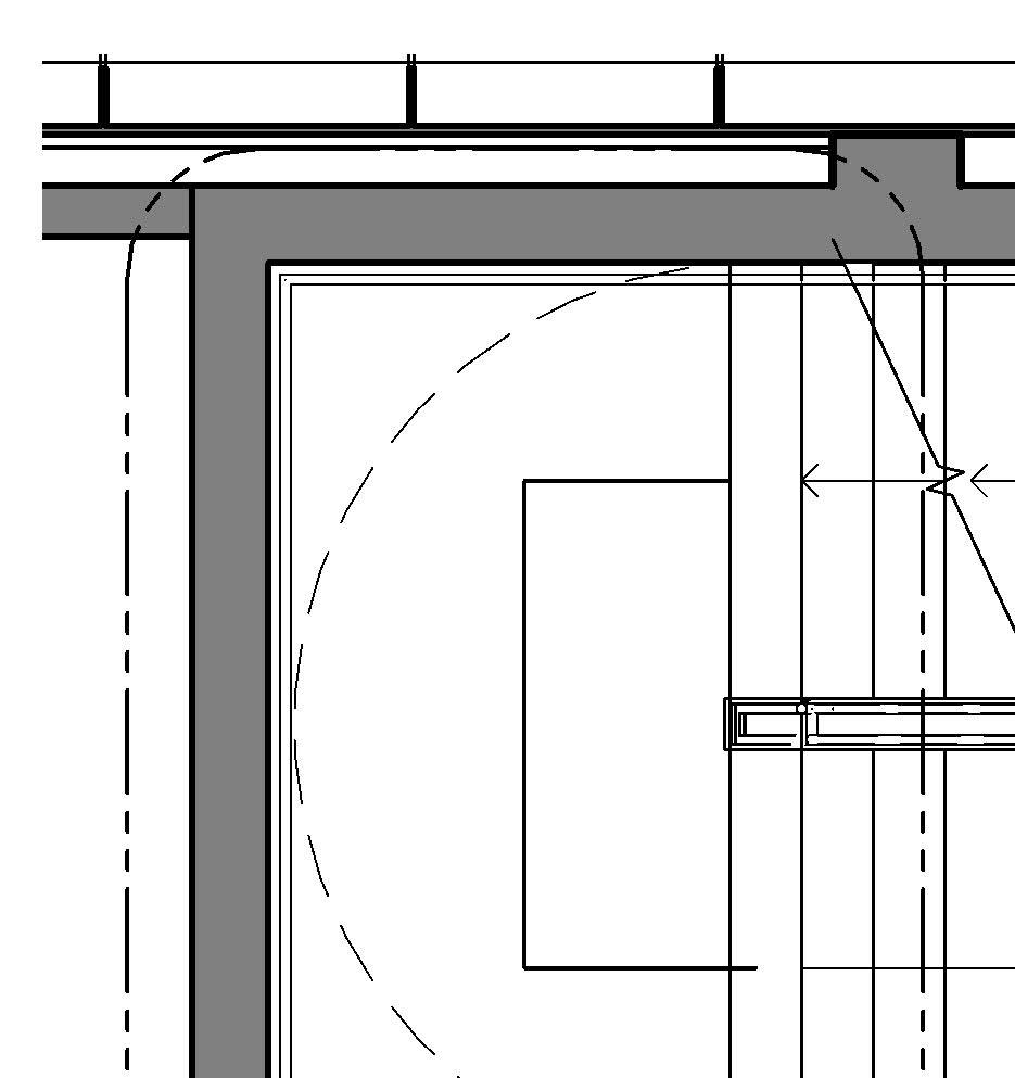
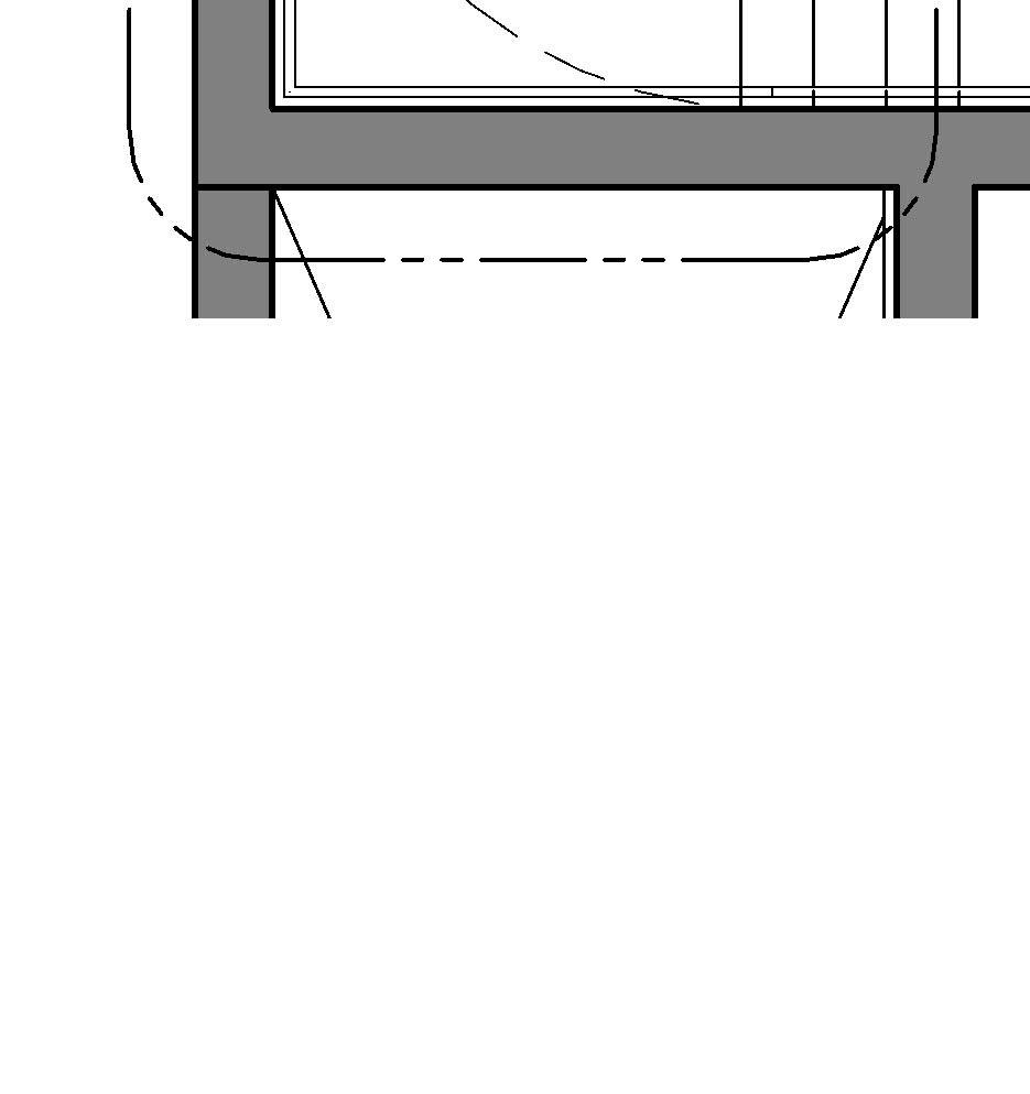
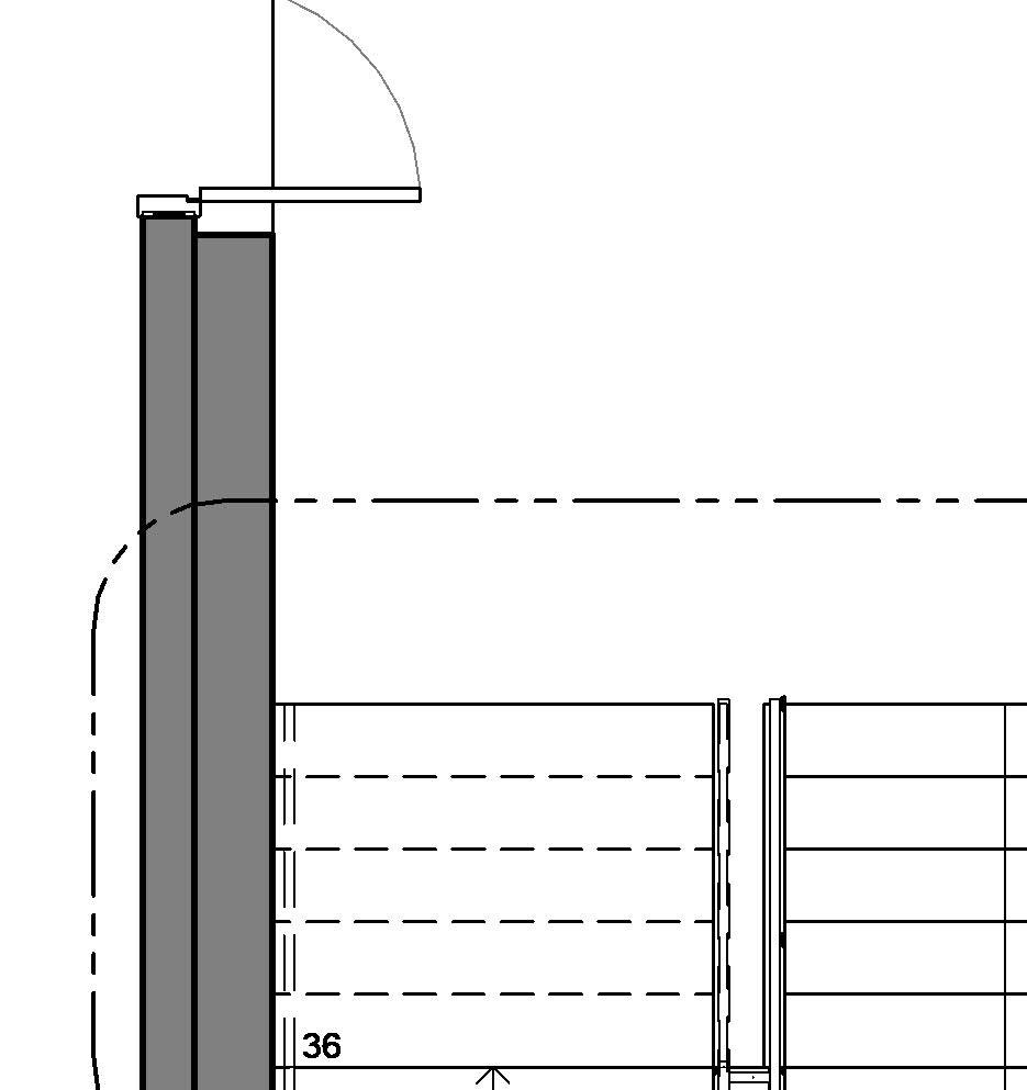
• Level of detailing: medium, which includes tags, width, clear width and length dimensions, clearances, distance to grids, steps numbering, directional arrows, railings, number of risers and treads per flight, egress doors, etc.
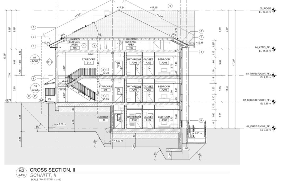
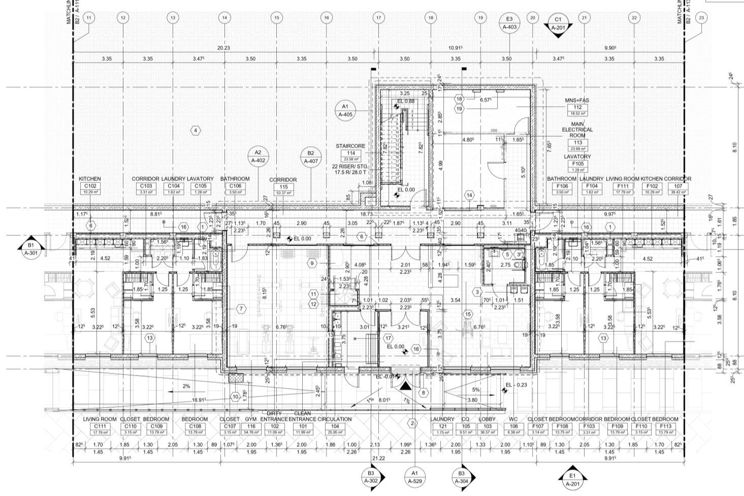
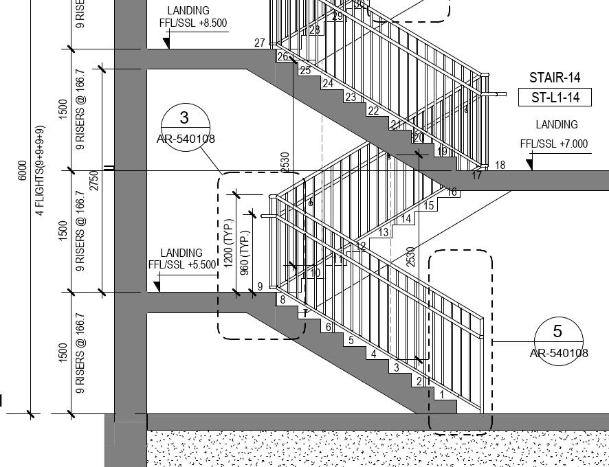
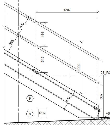
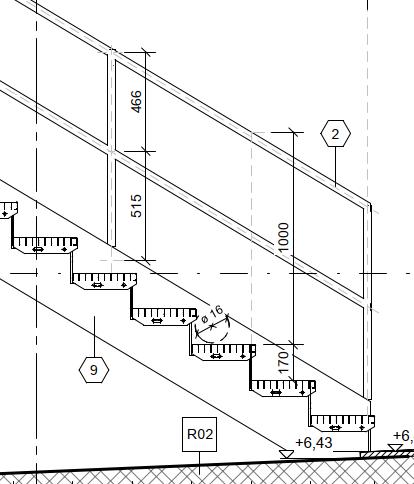
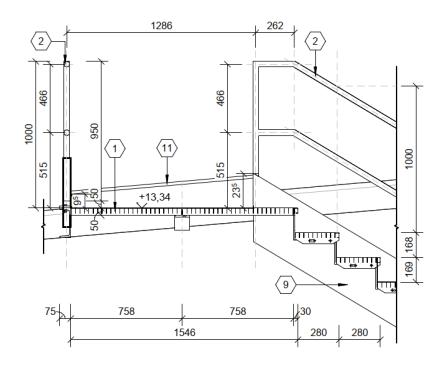
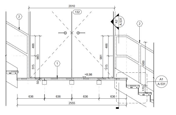
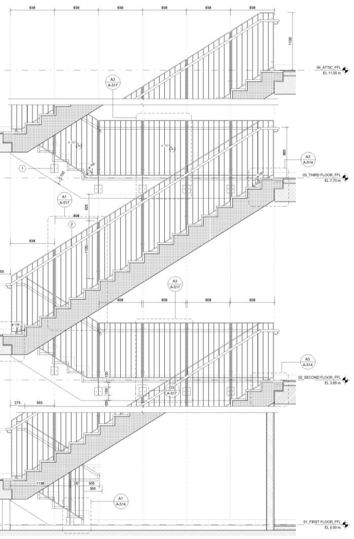
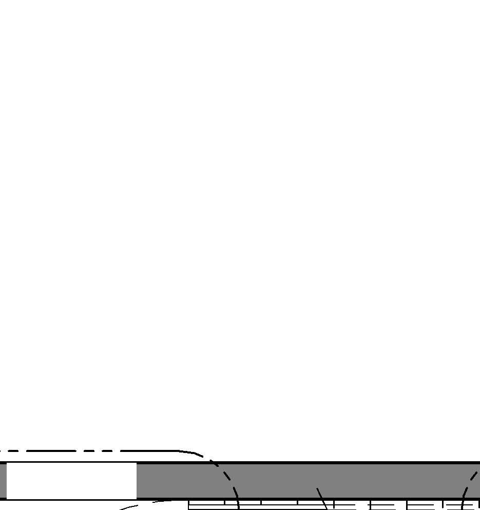
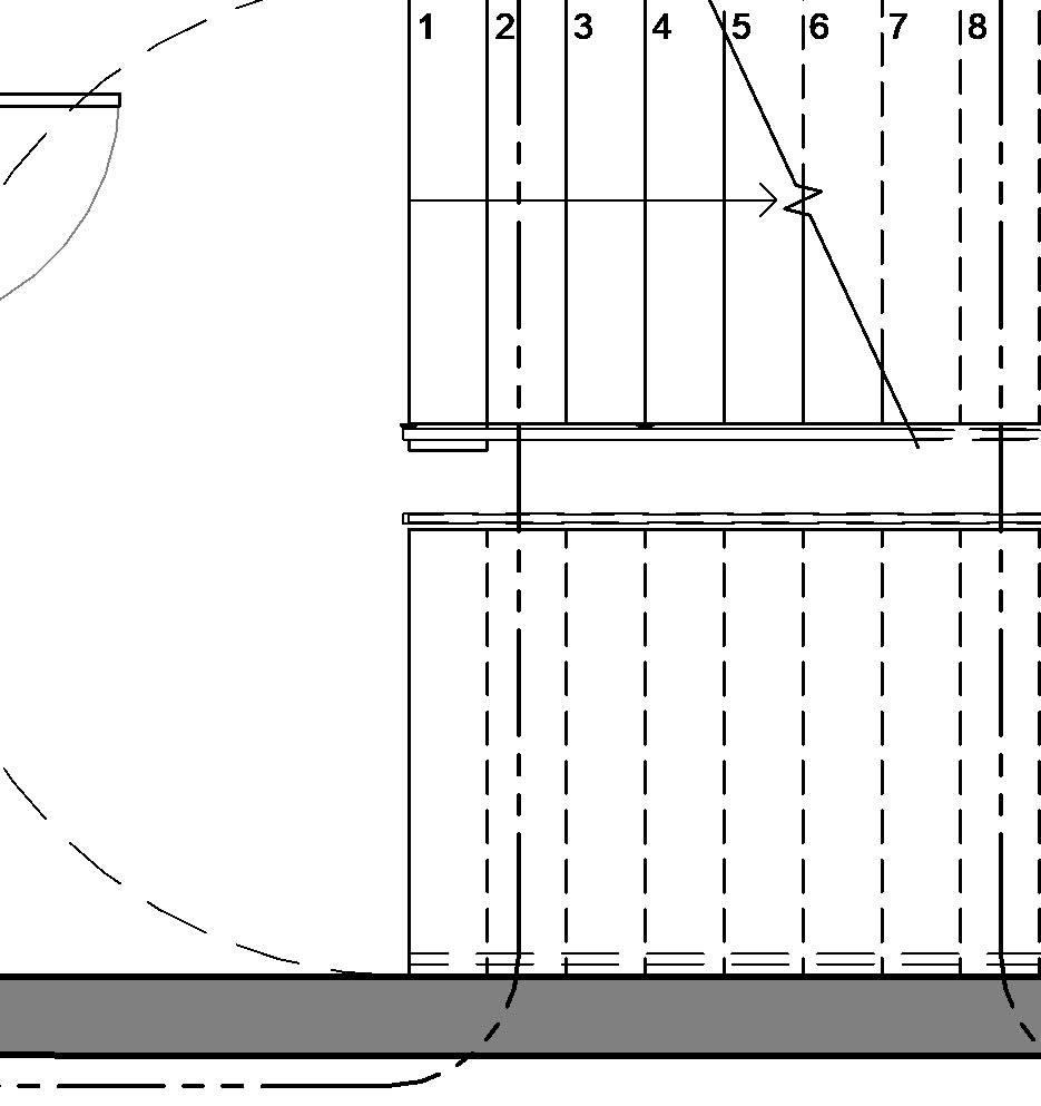
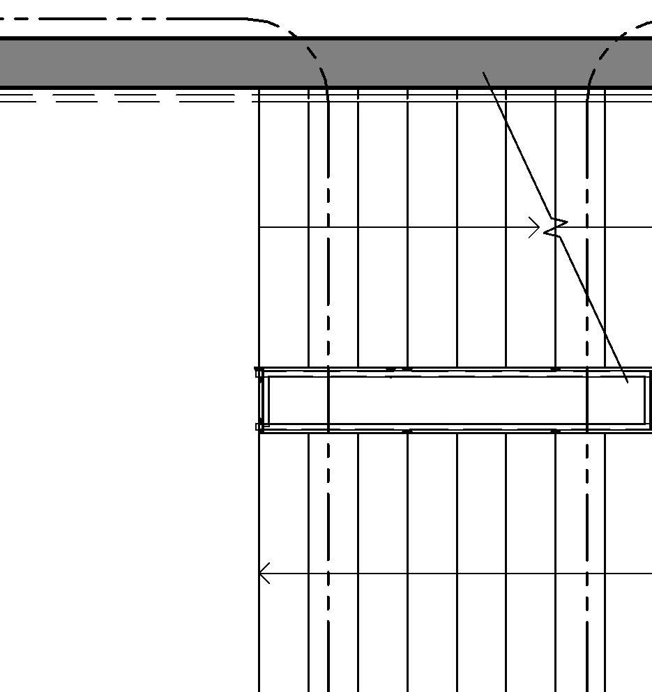
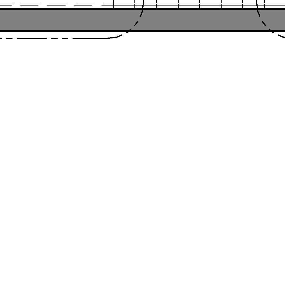
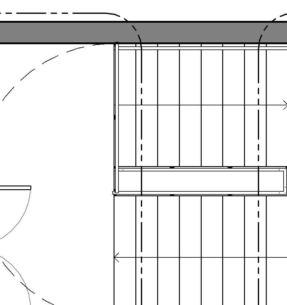
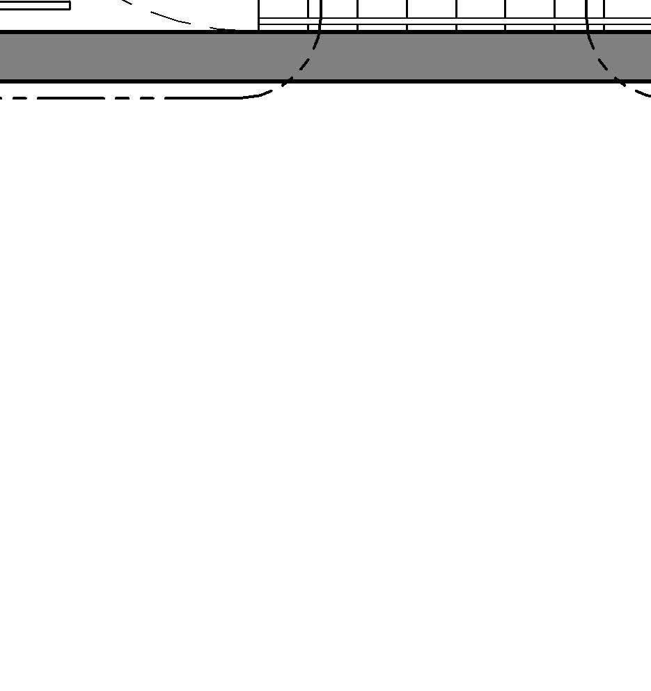
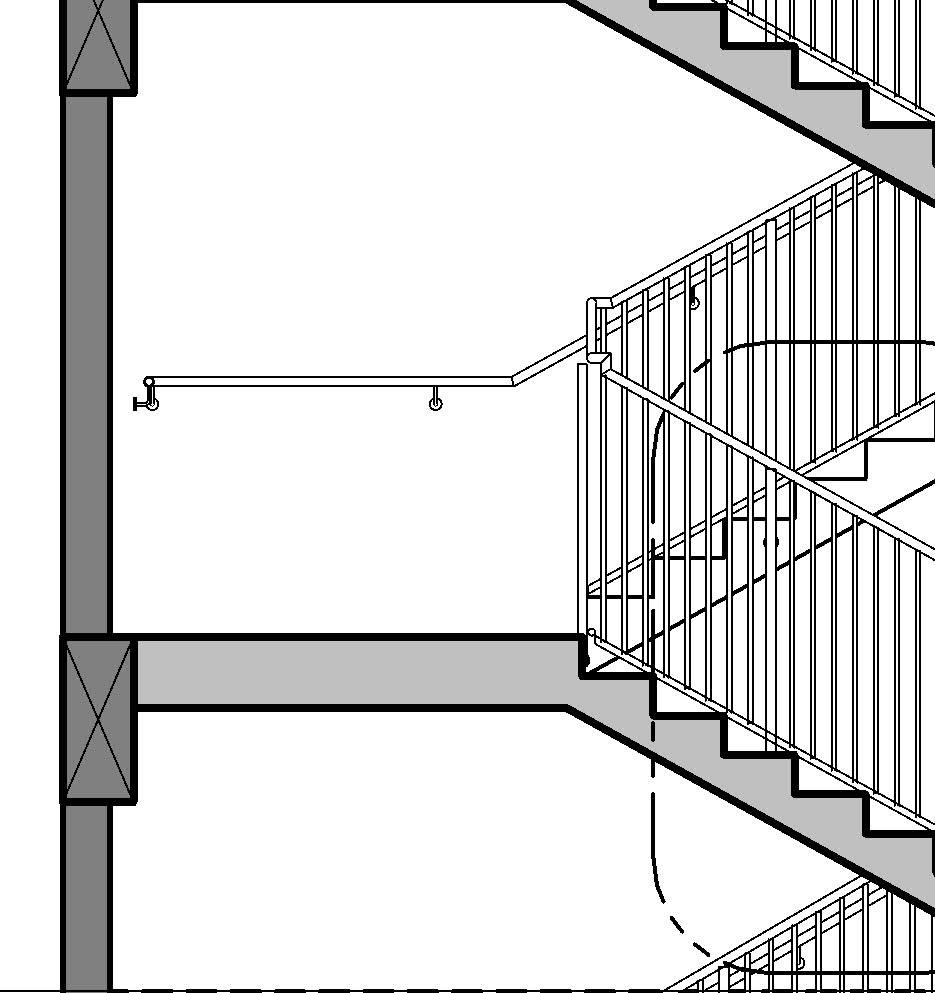
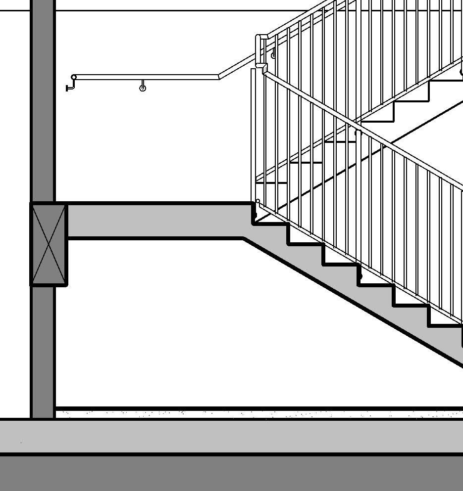
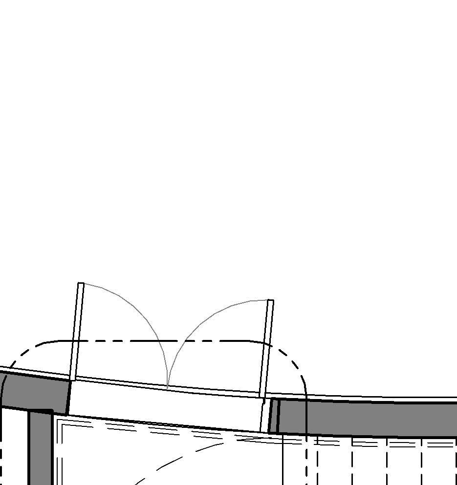
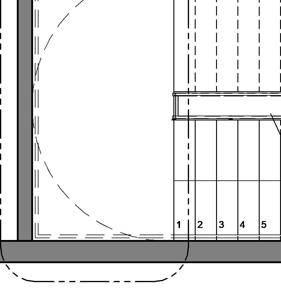
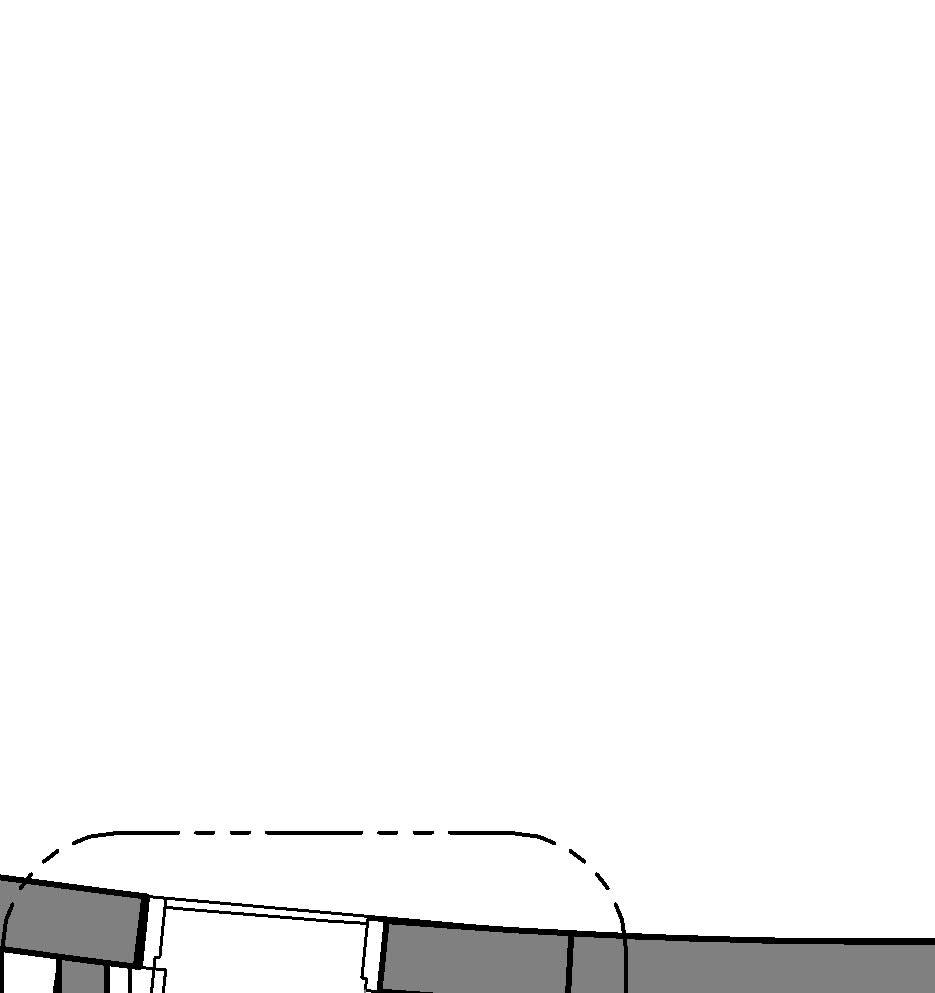
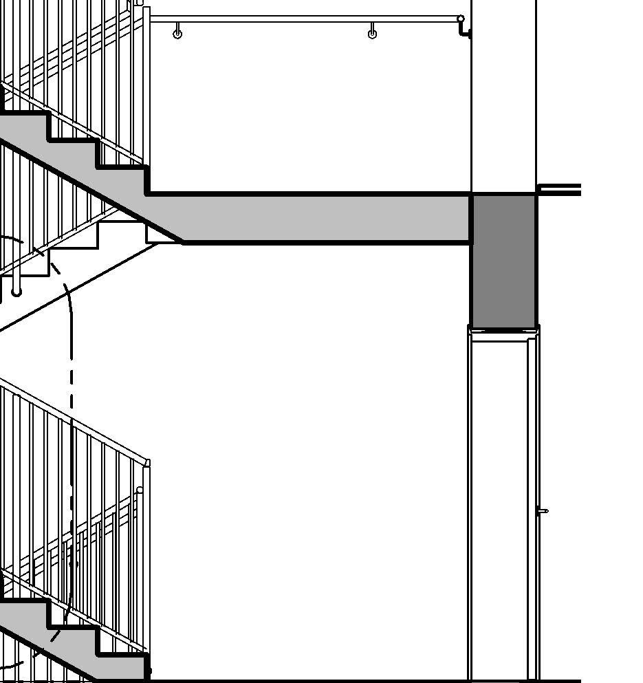
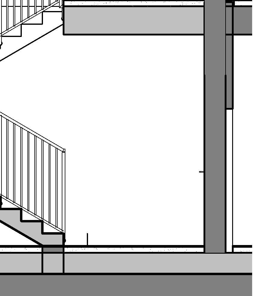
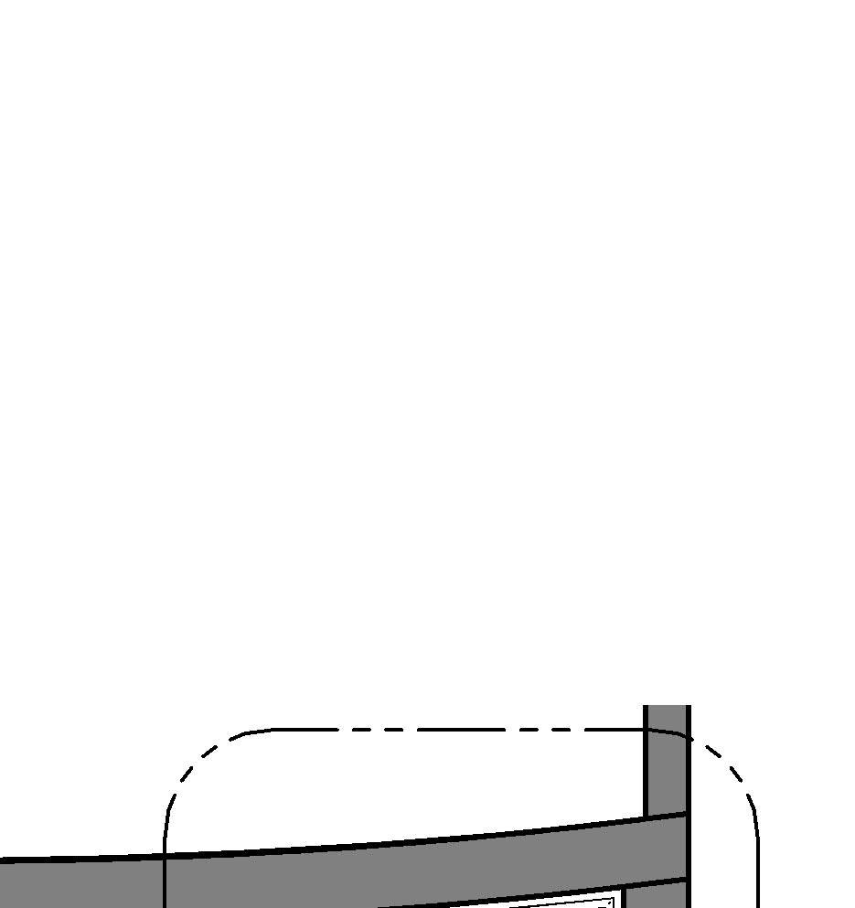
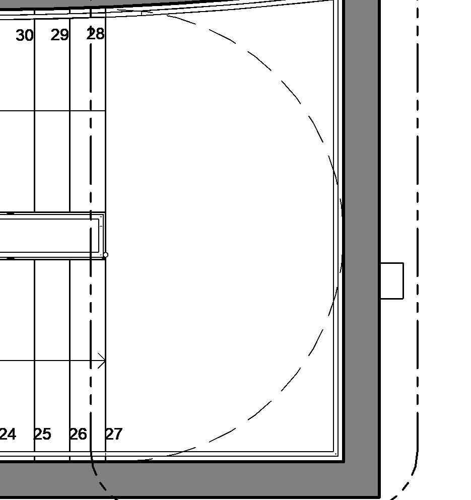
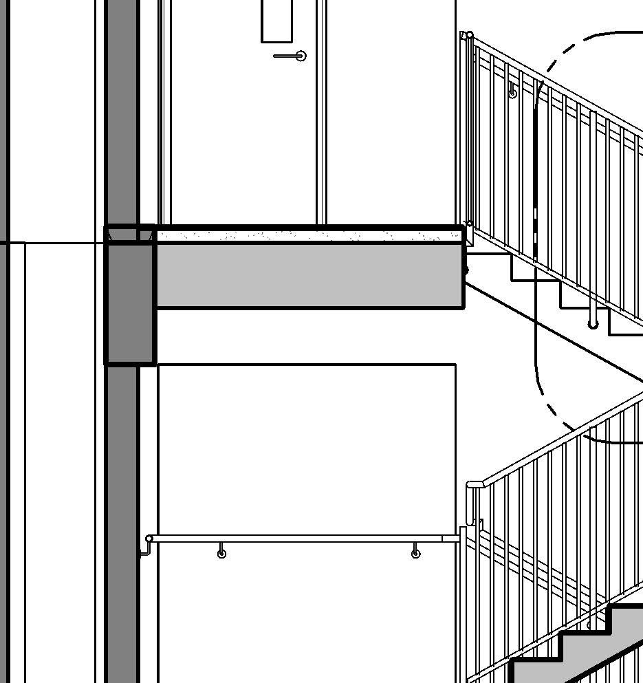
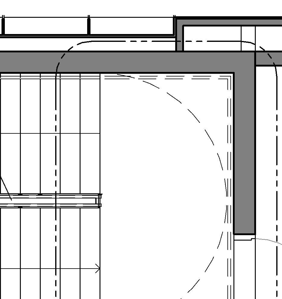
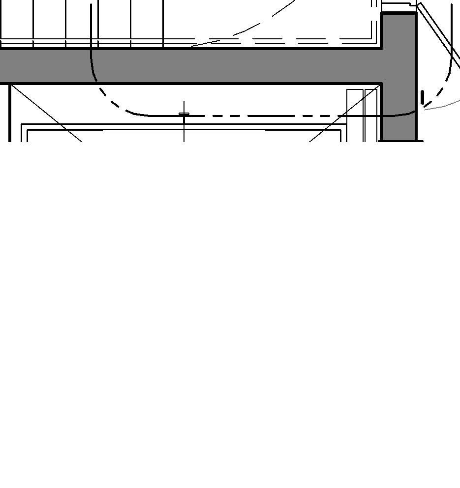
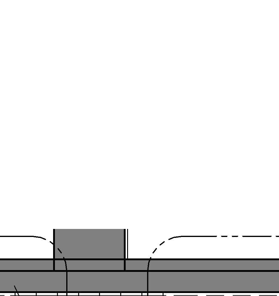
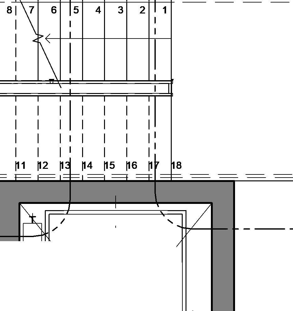
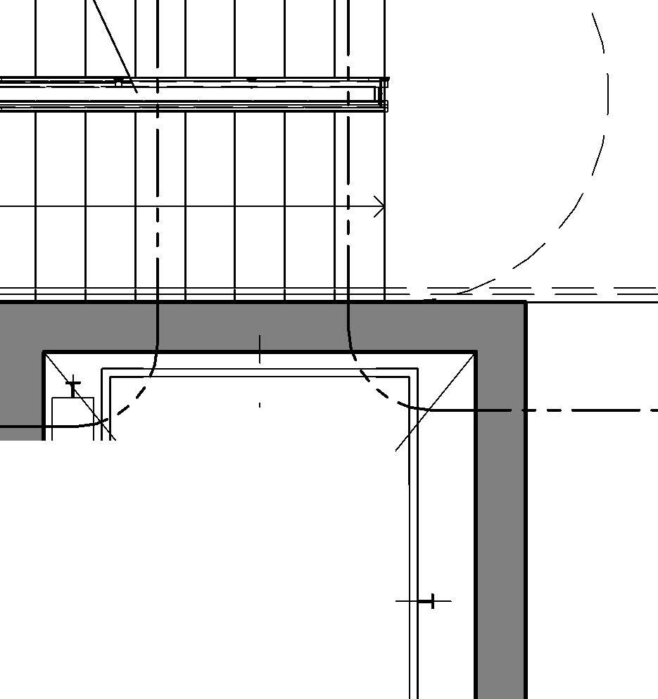
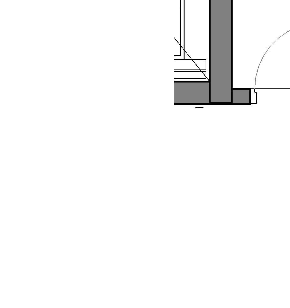
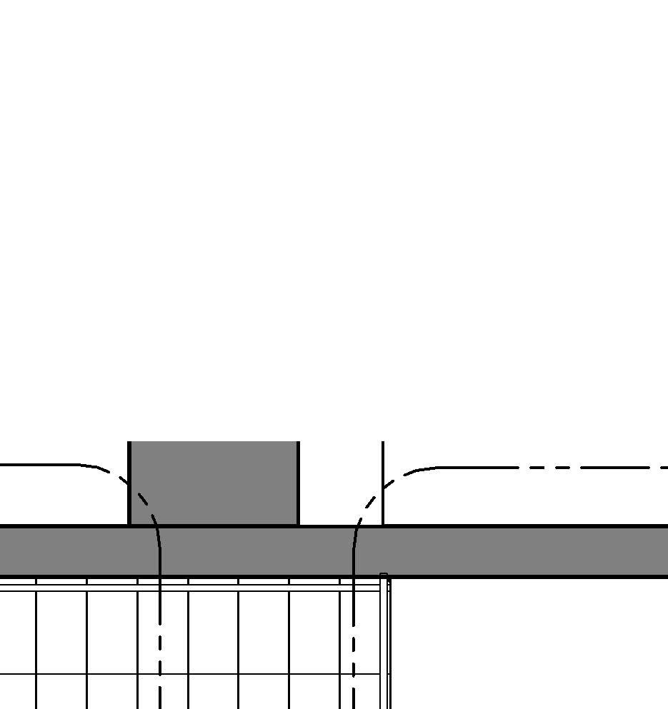
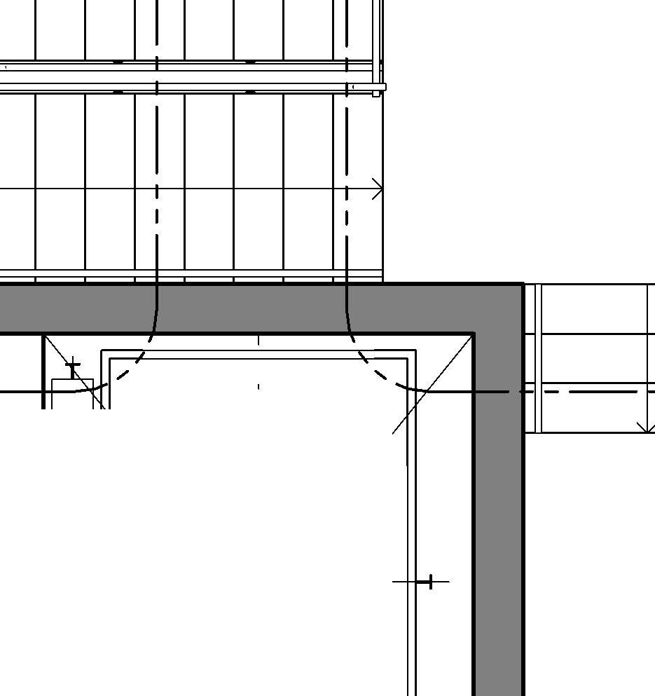
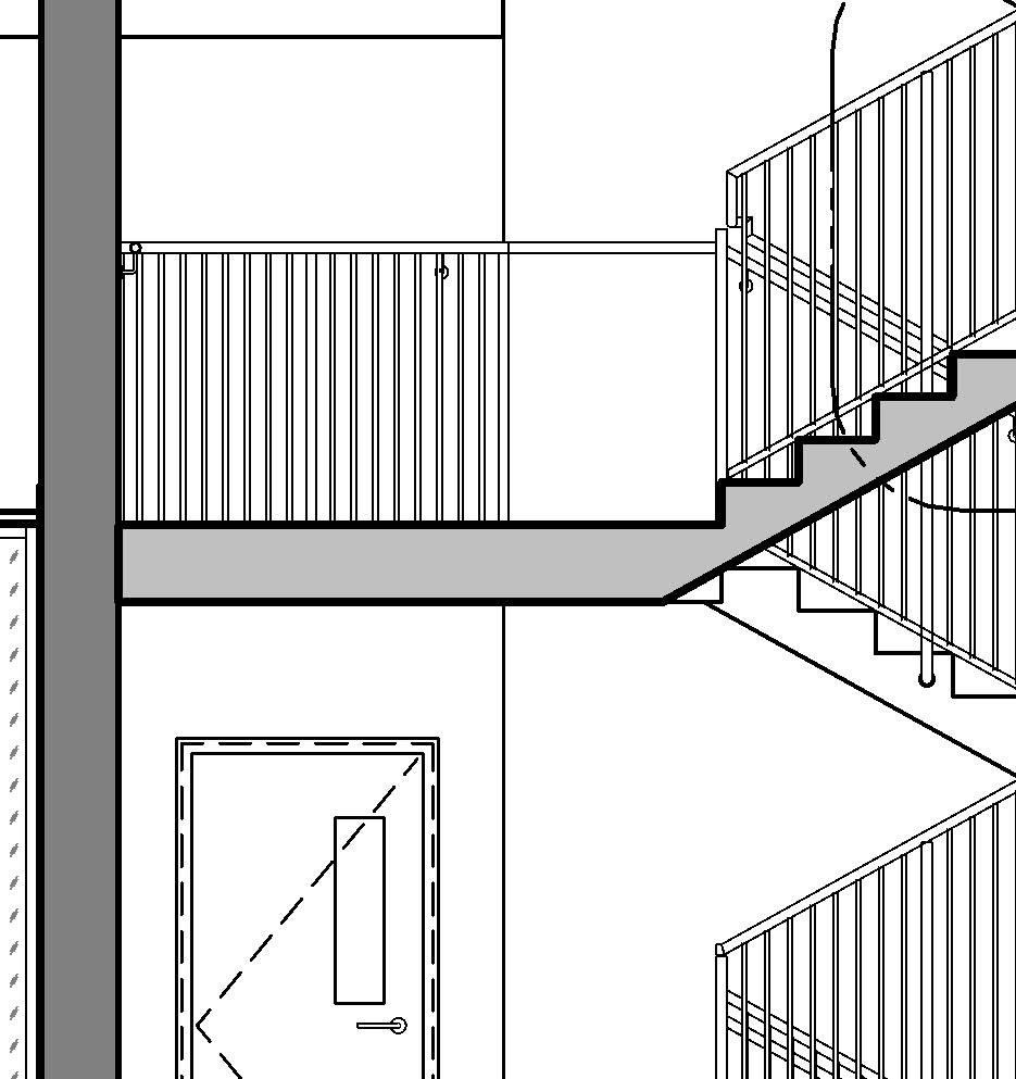
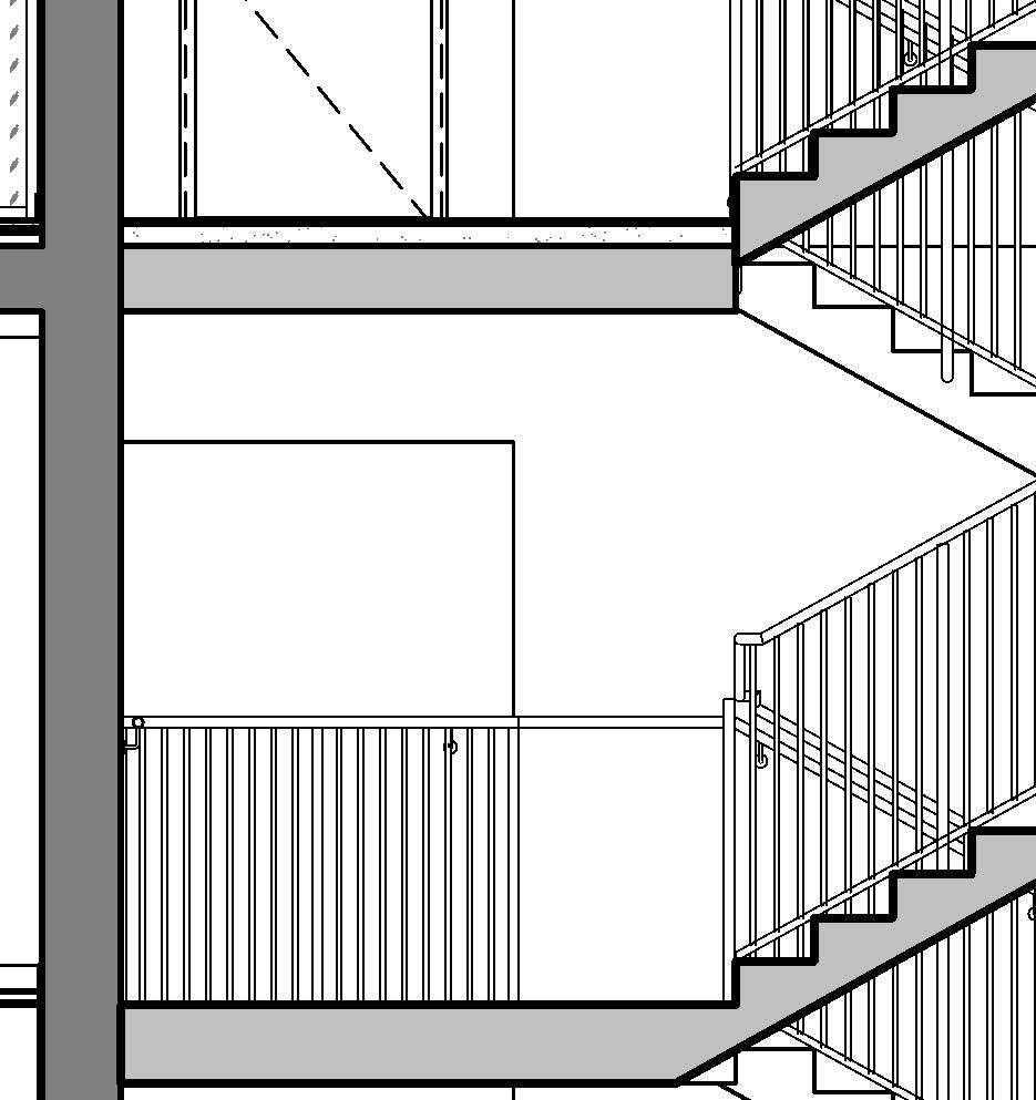
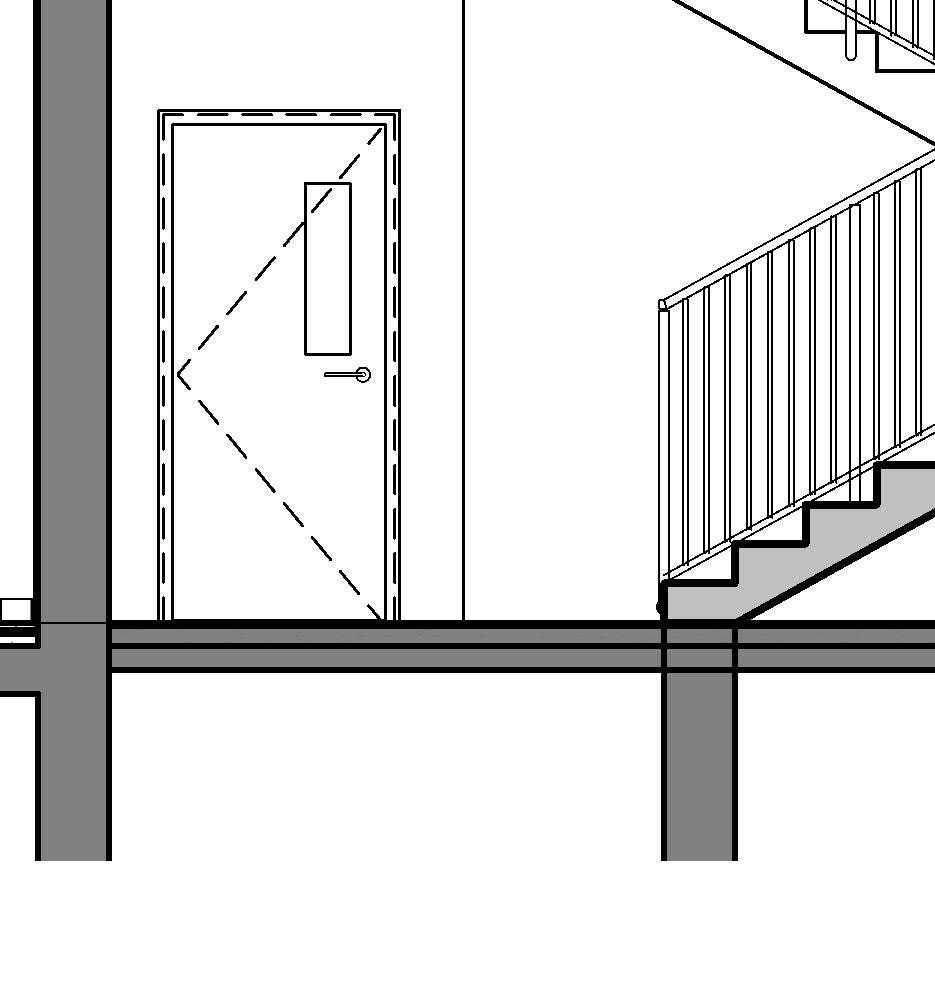
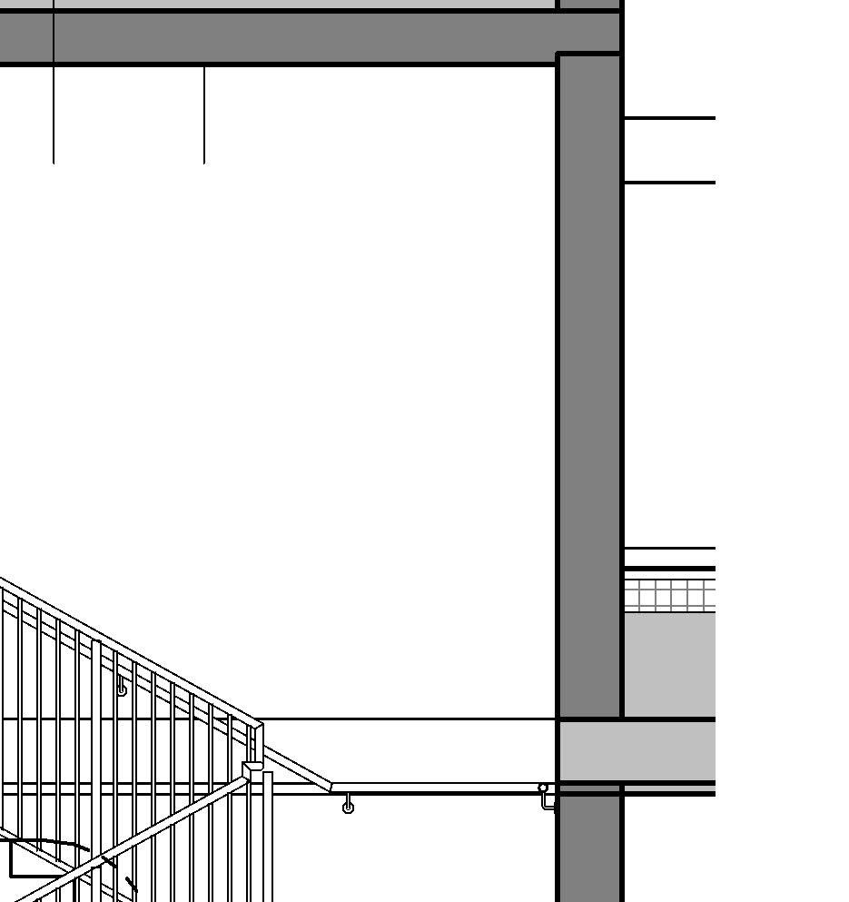
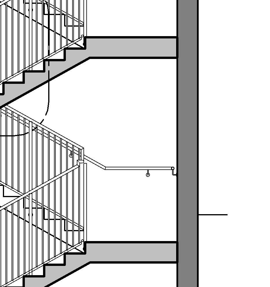
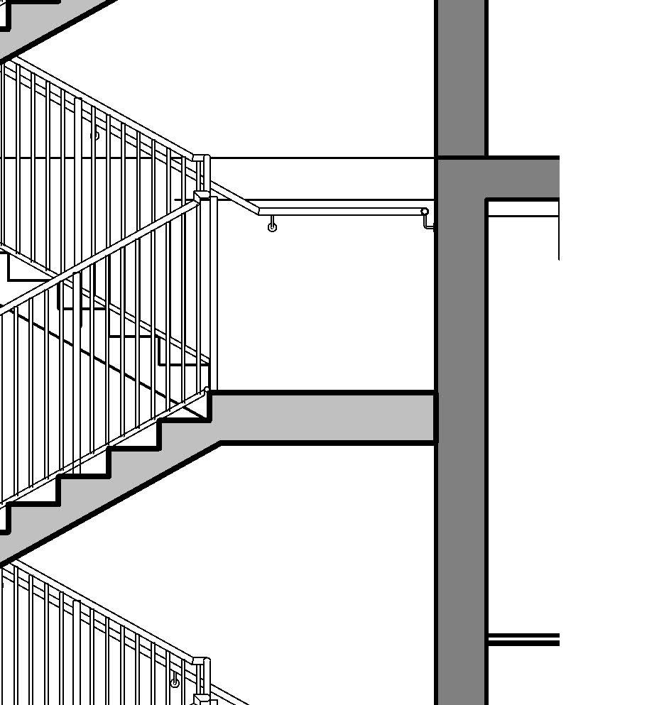
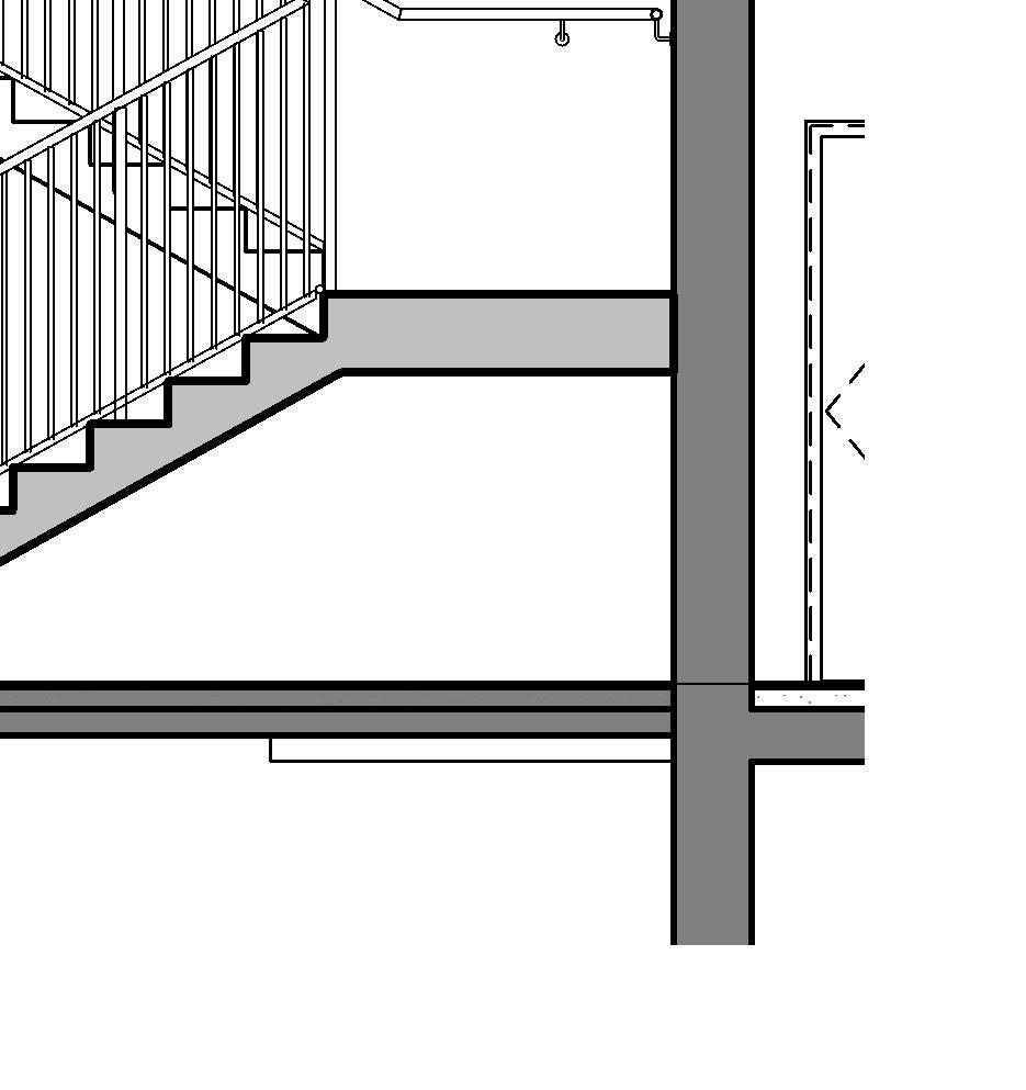
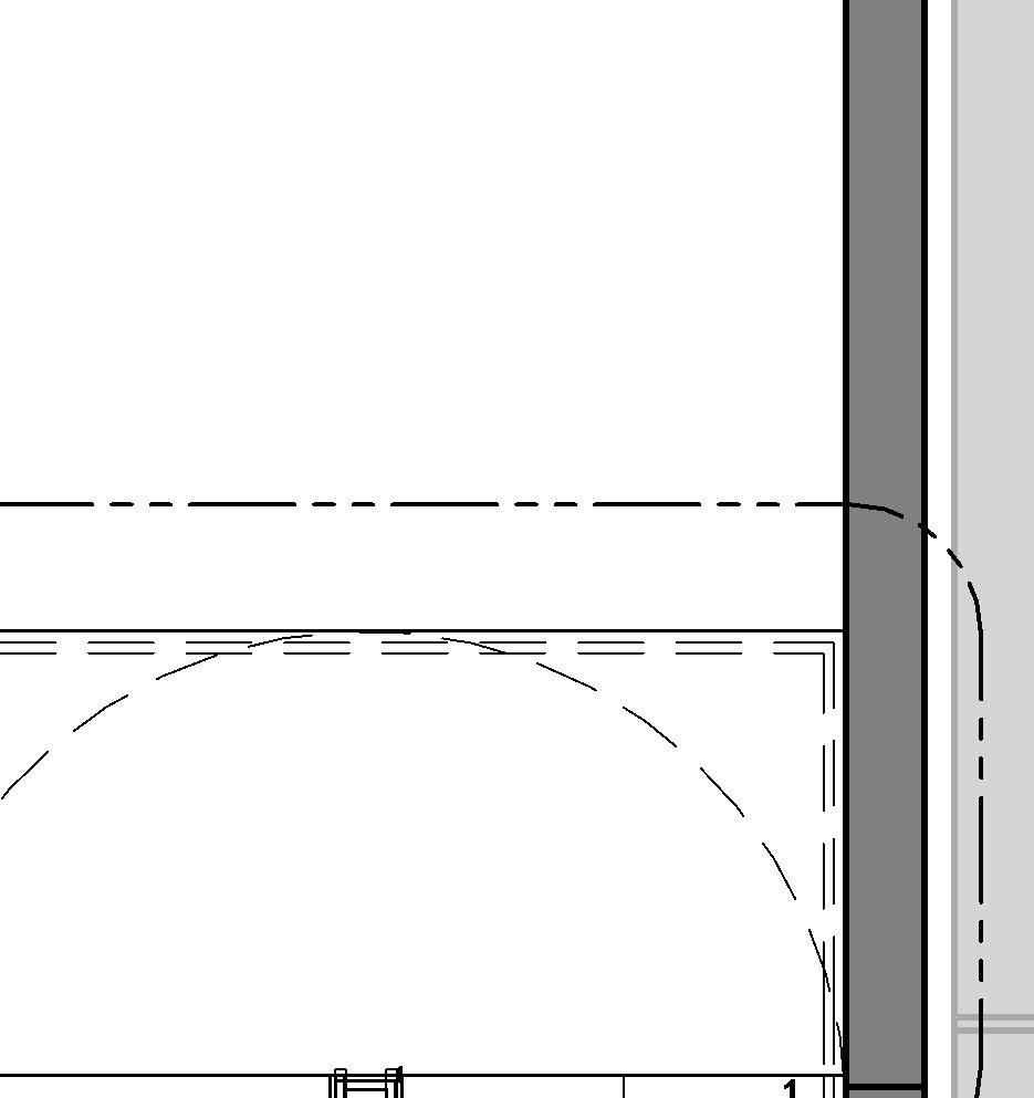
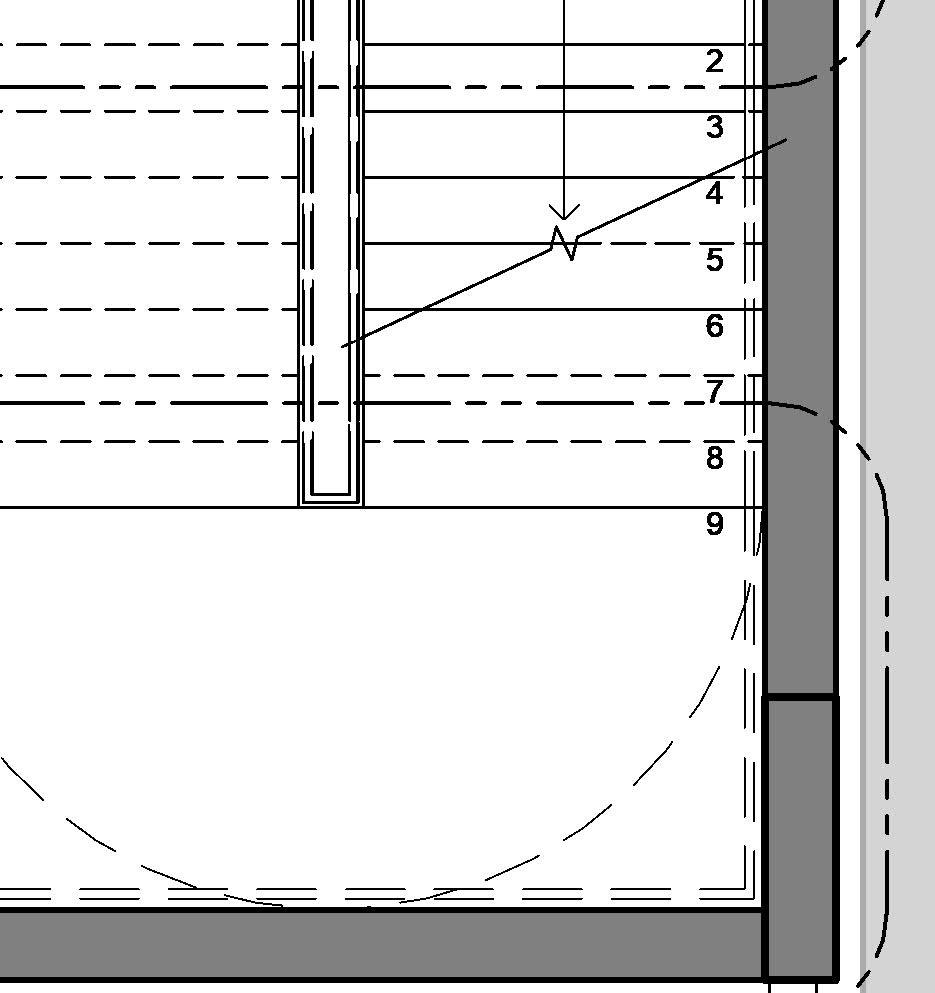
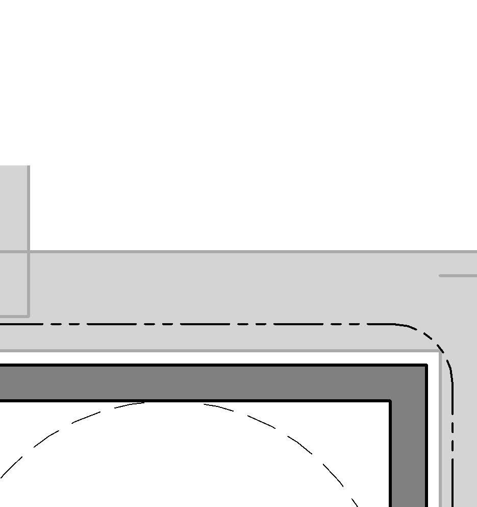
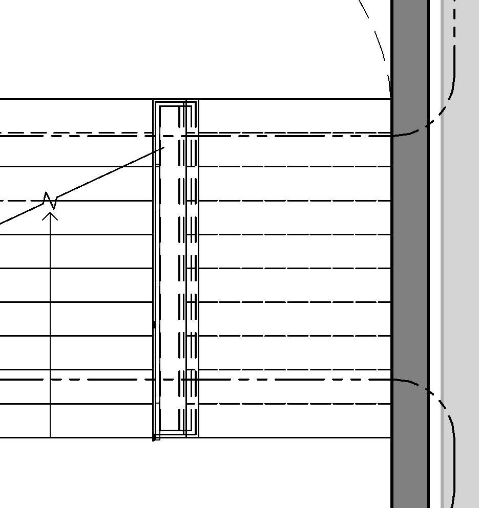
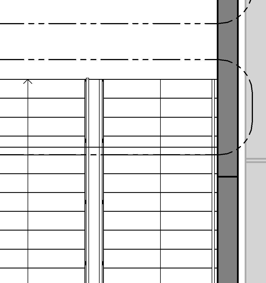
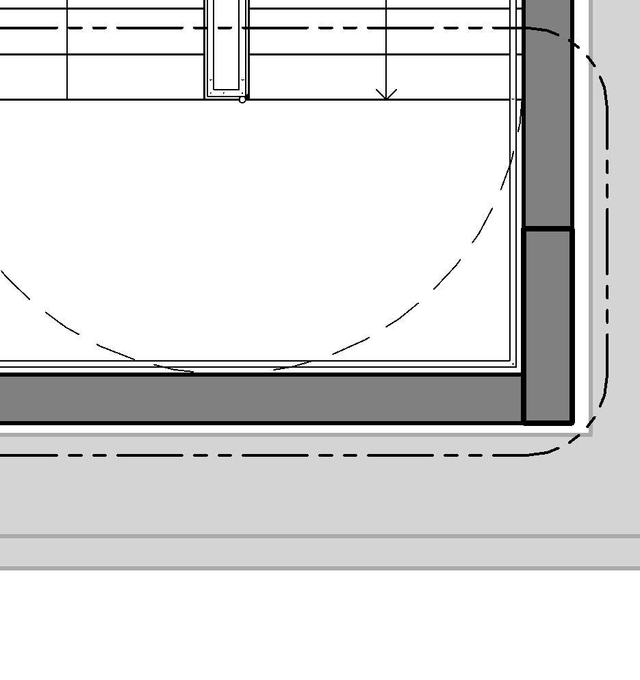
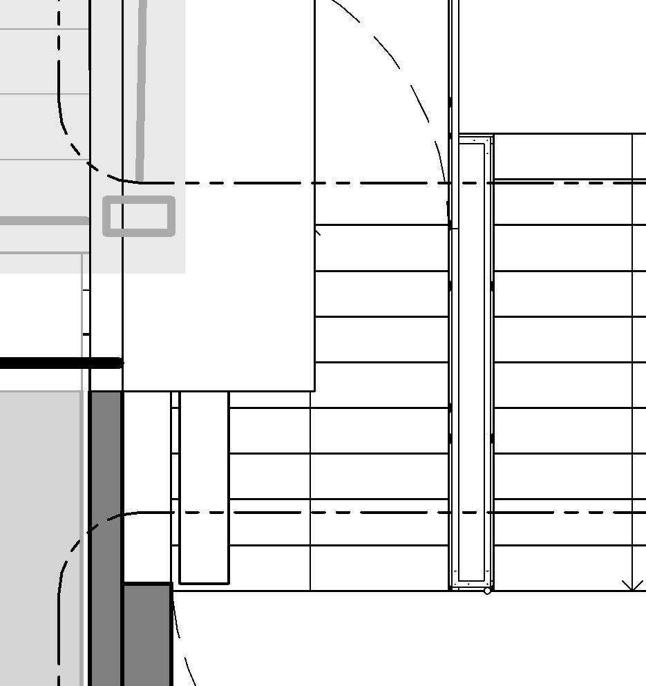
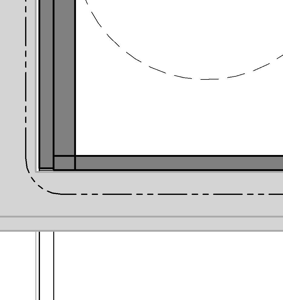
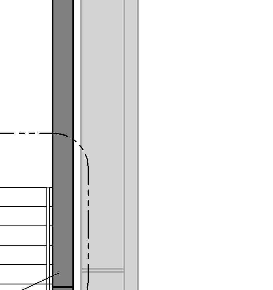
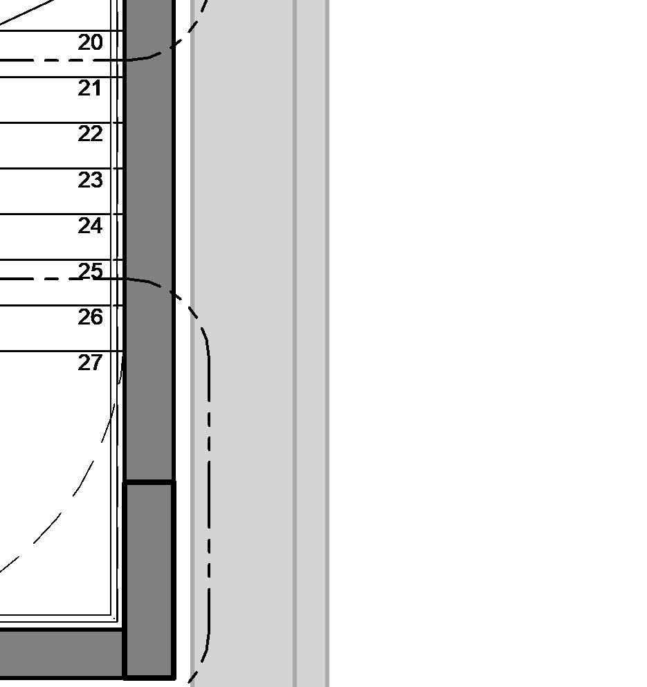
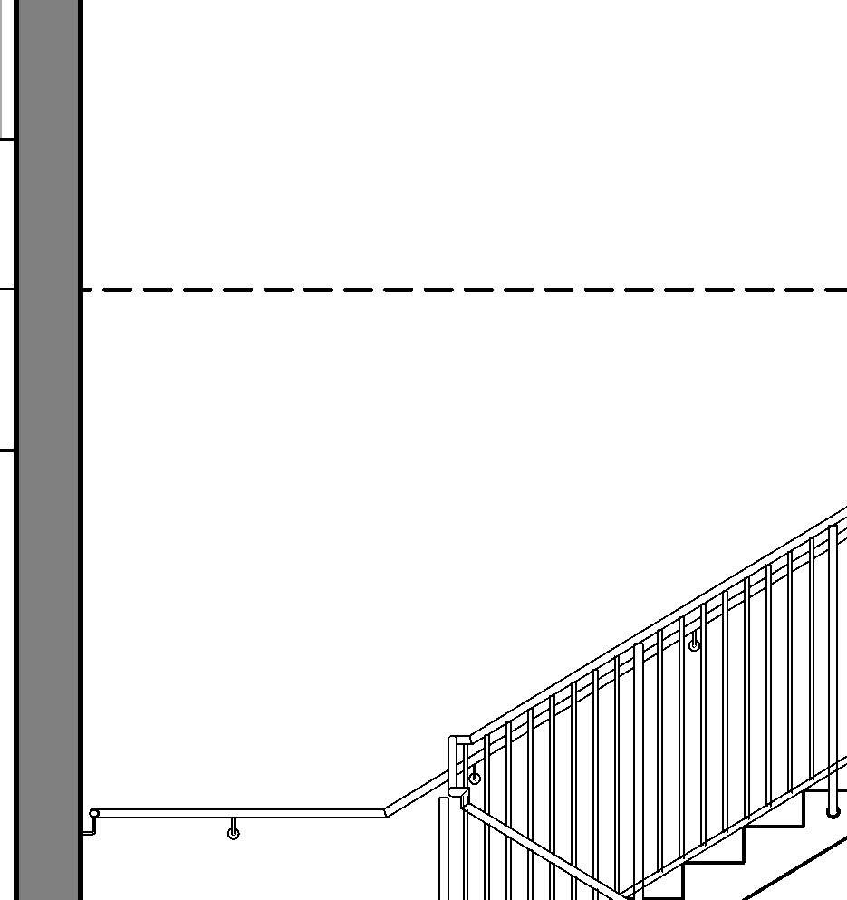
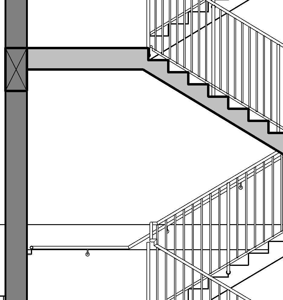
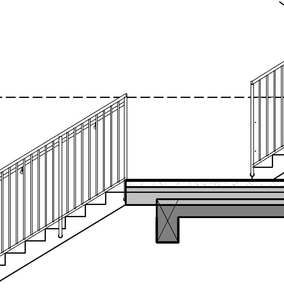
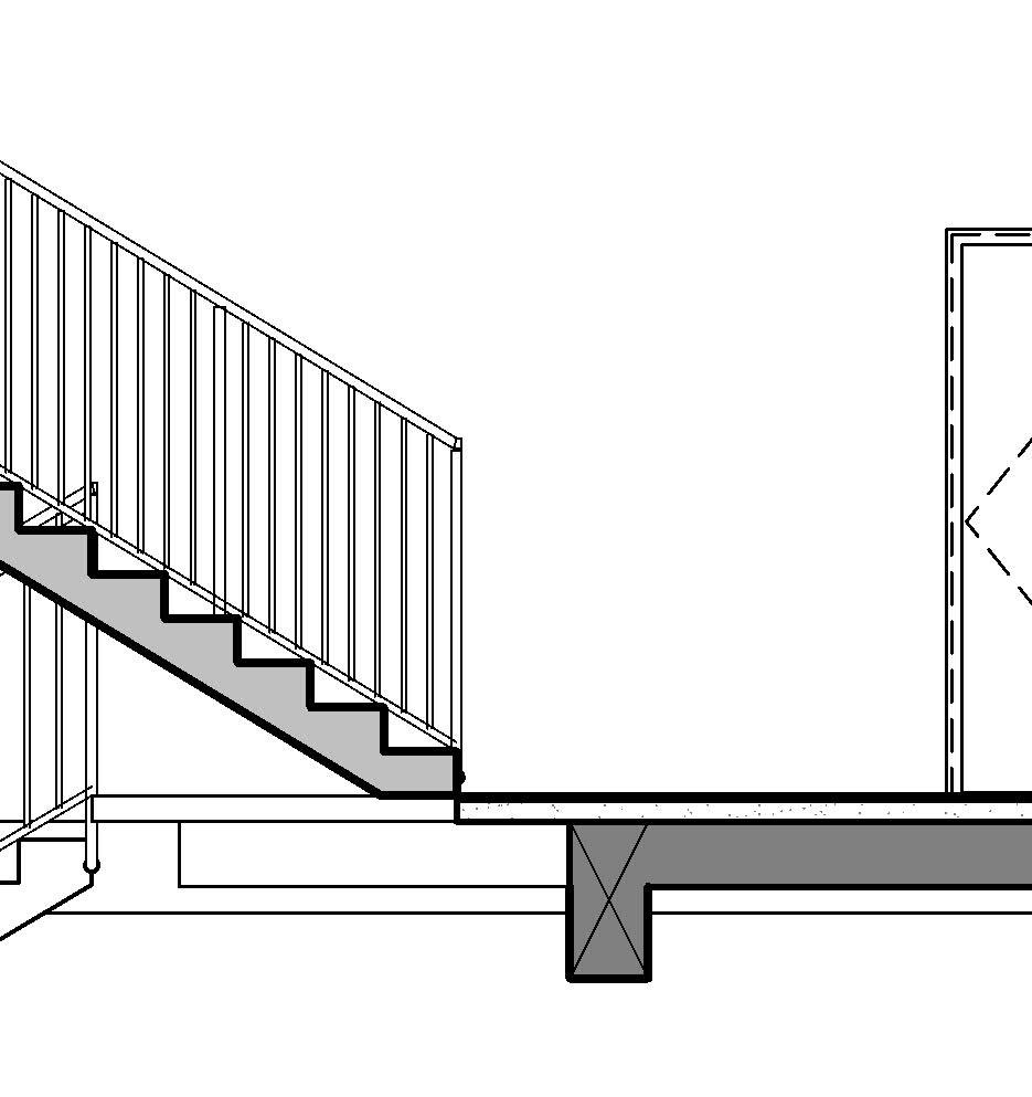
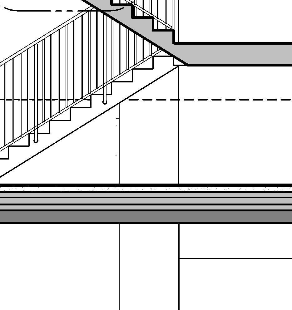
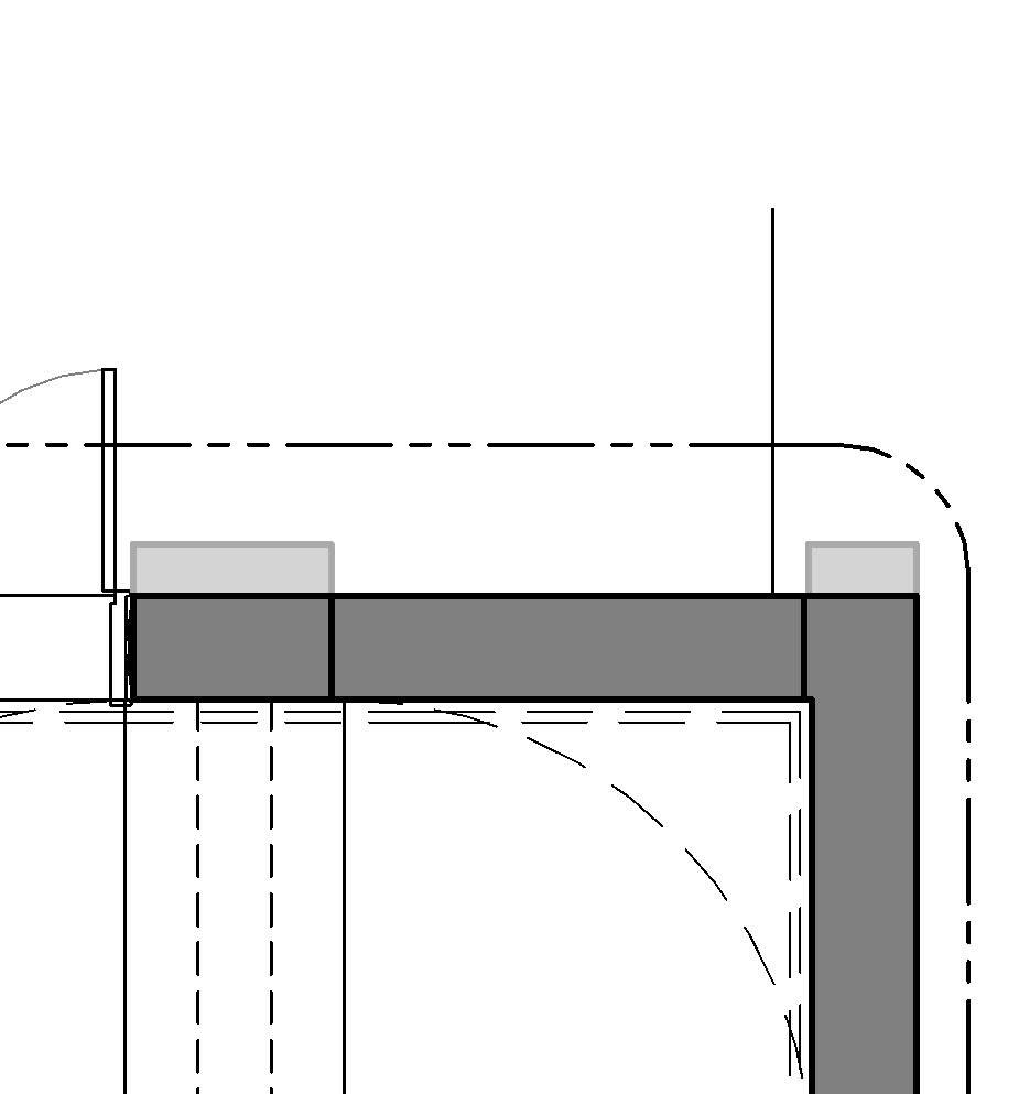
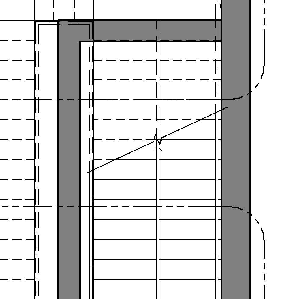
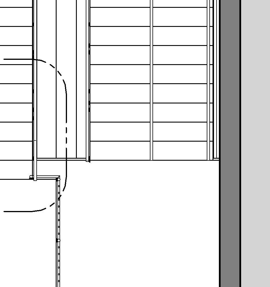
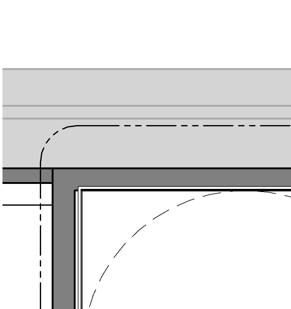
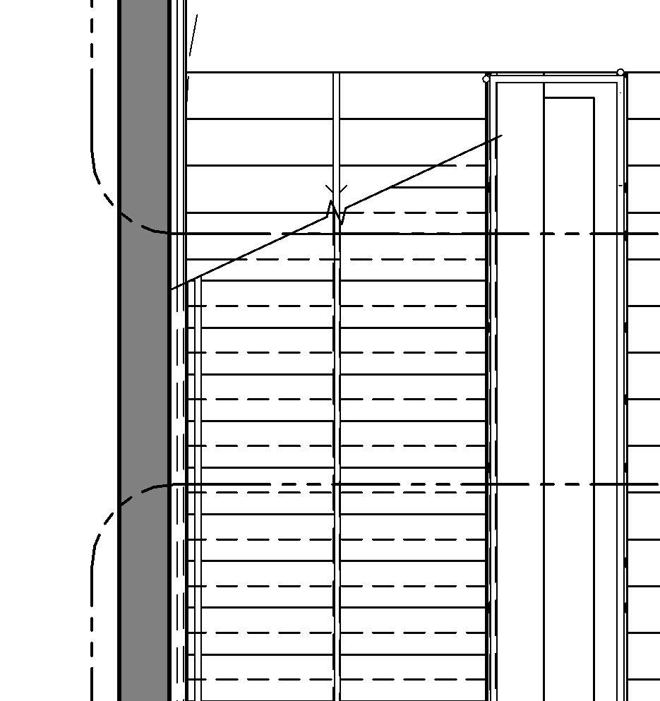
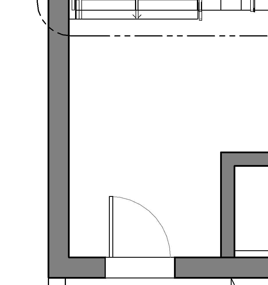
Section and plans at 1:50 ↓→
* Find these examples’ full documentation in chapter 09
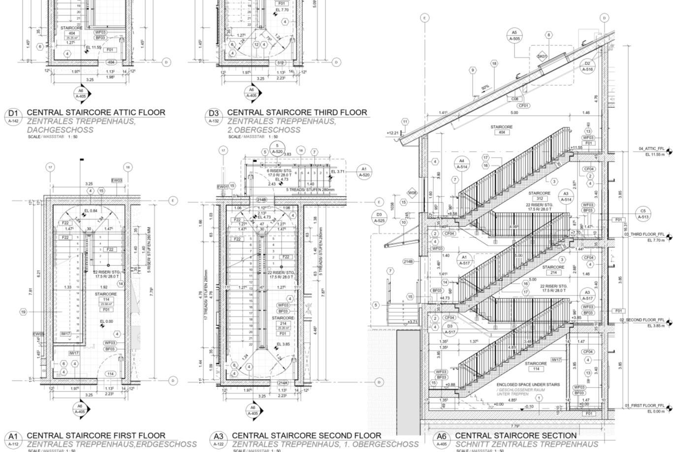
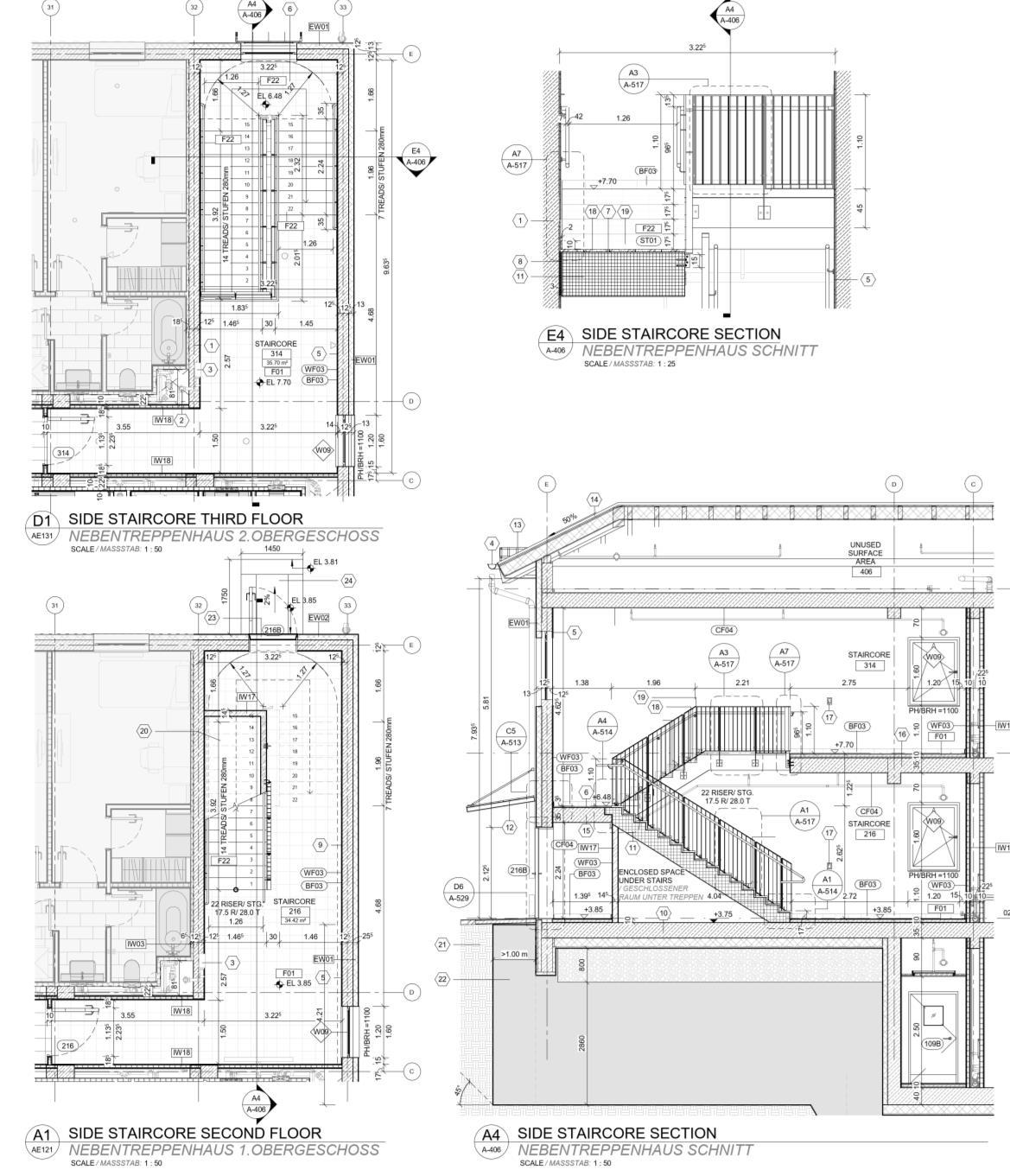
Chart how to find the stairs in my project
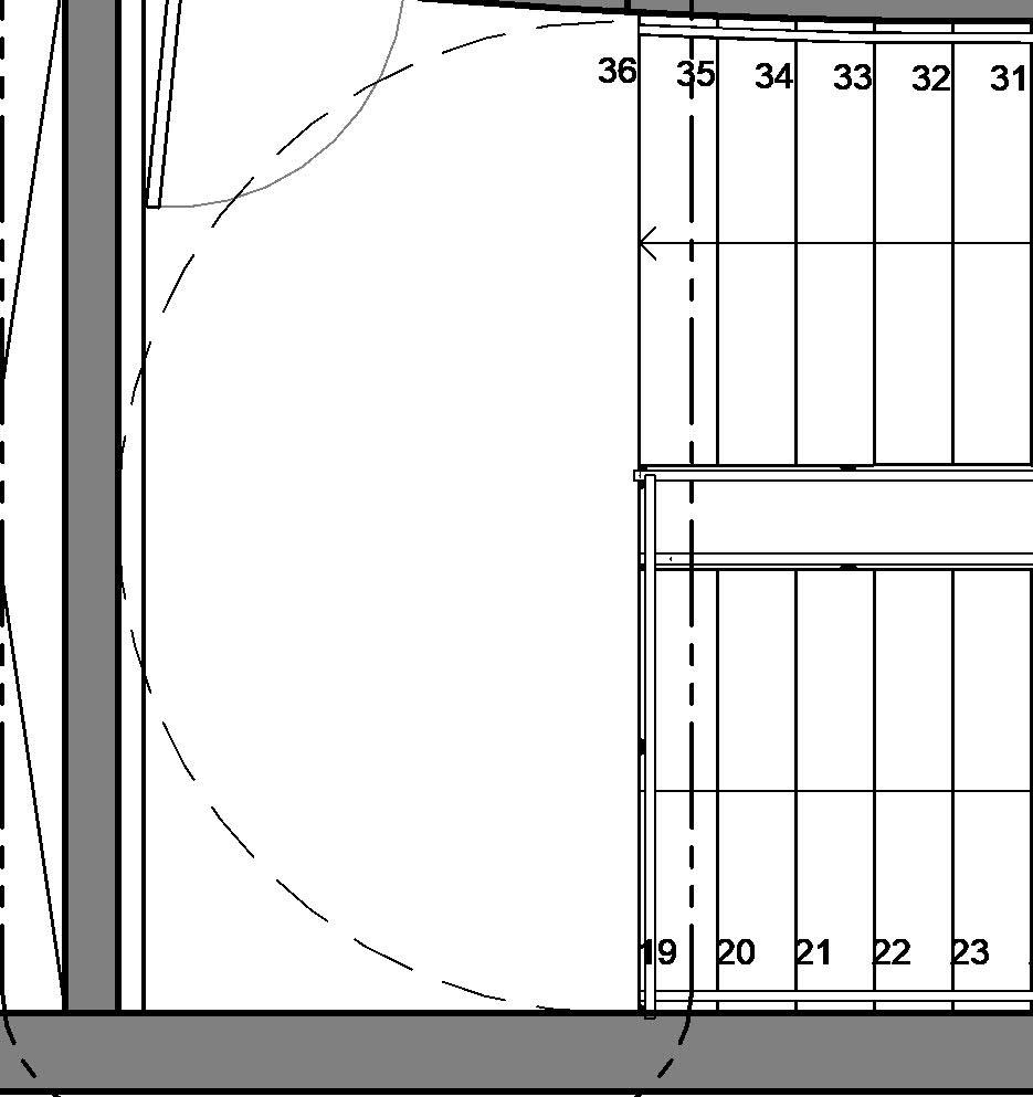
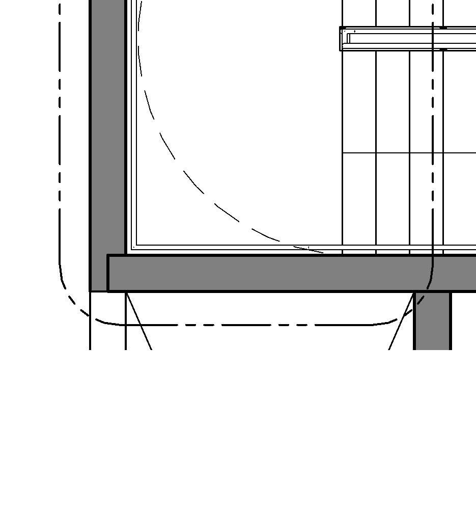
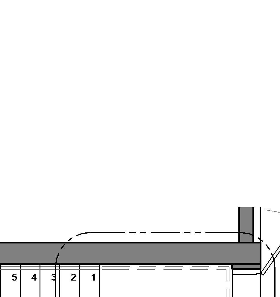
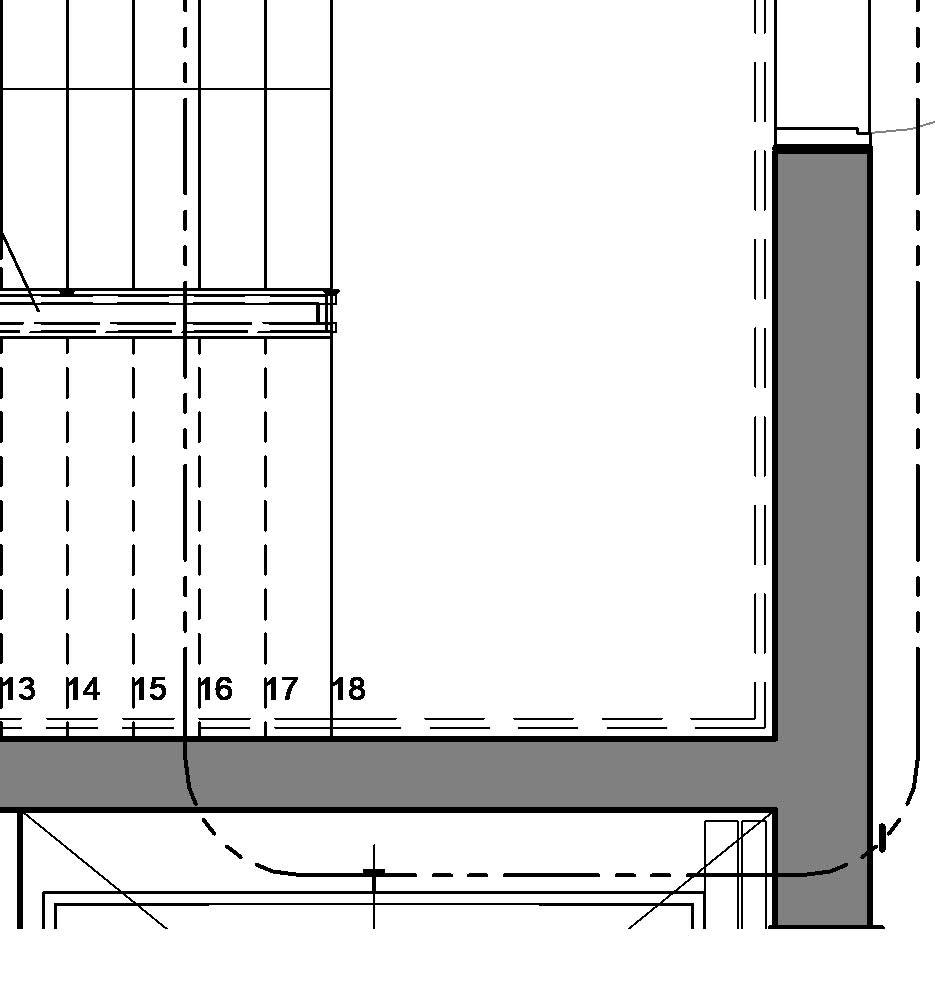
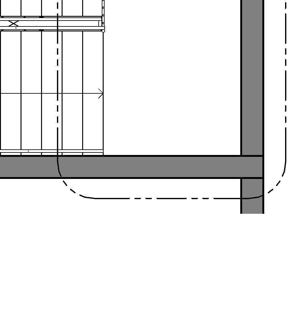
3.2 Second level of information
• Purpose: detailing the dimensions, the different levels that the stair covers, and its components
• Type of drawing: enlarged plans, sections and axonometric views
• Usual scales: from 1:50 to 1:20
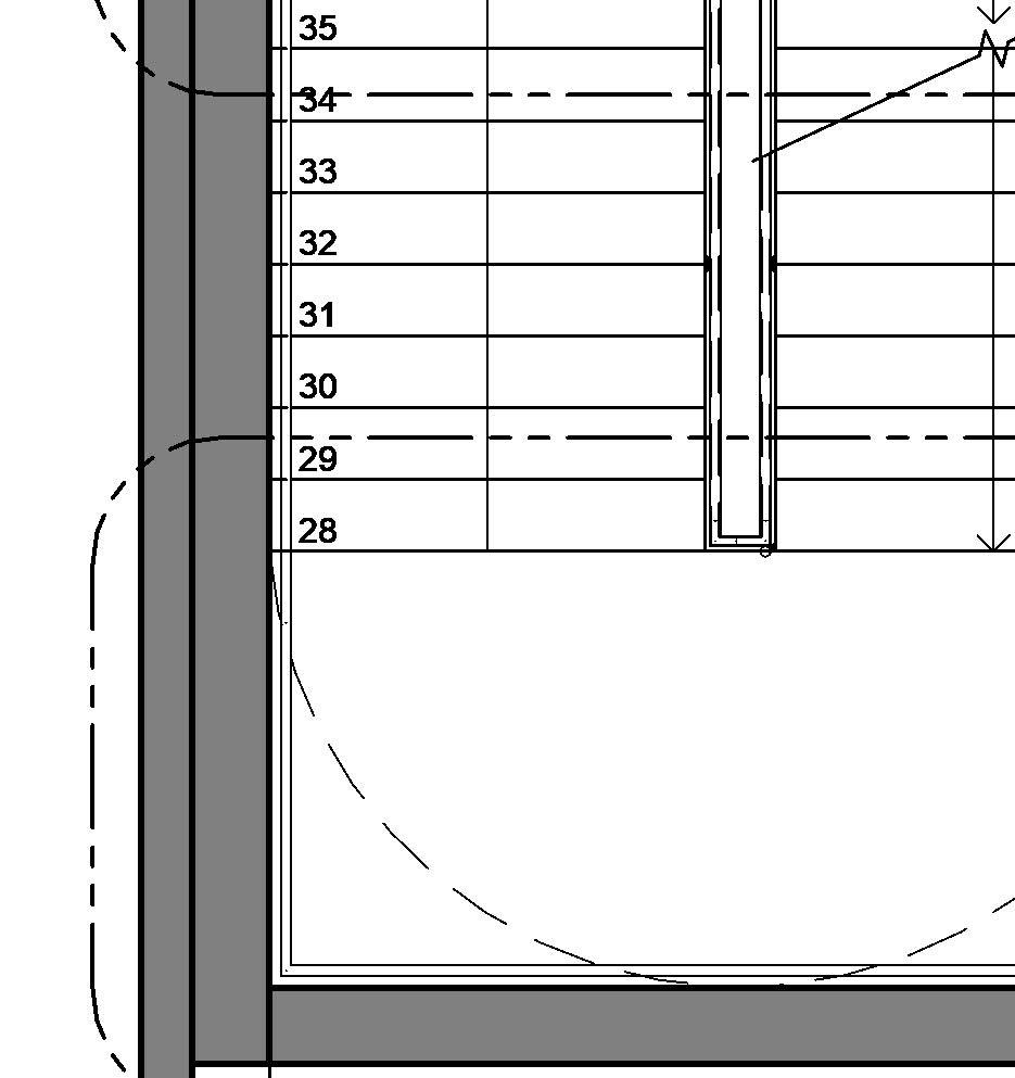
• Level of detailing: medium, which includes tags, width, clear width and length dimensions, clearances, distance to grids, steps numbering, directional arrows, railings, number of risers and treads per flight, egress doors, etc.
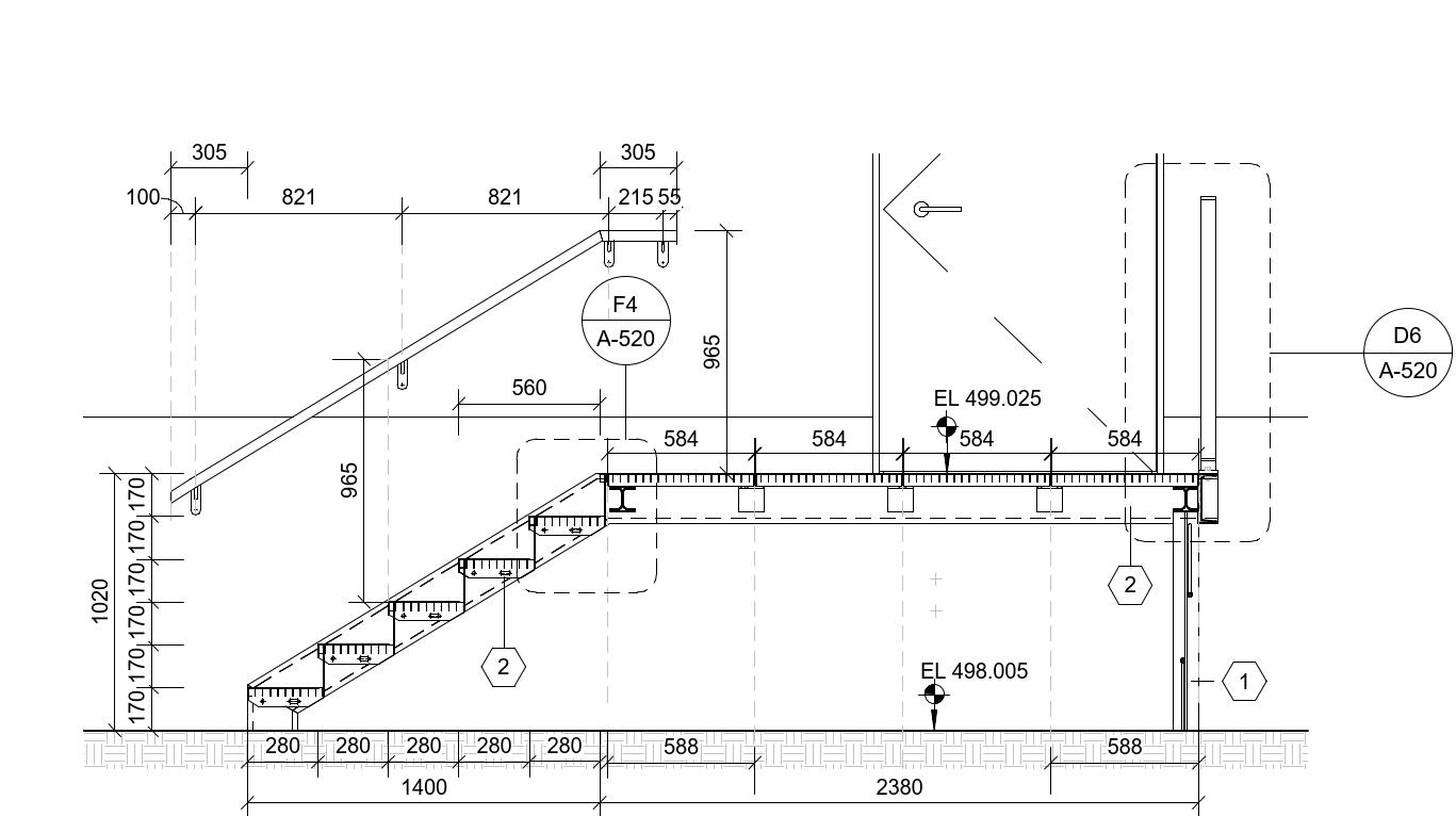
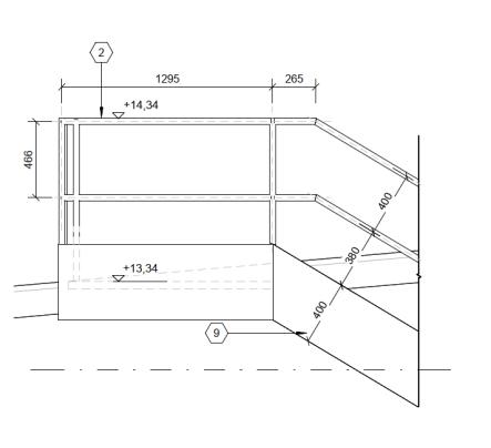
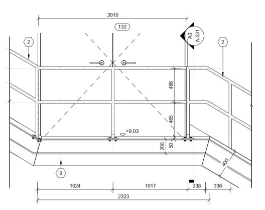
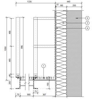
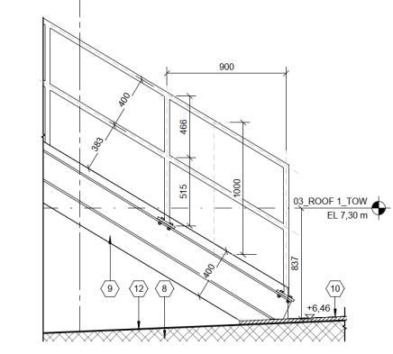
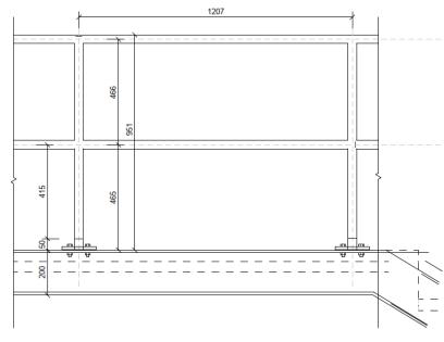
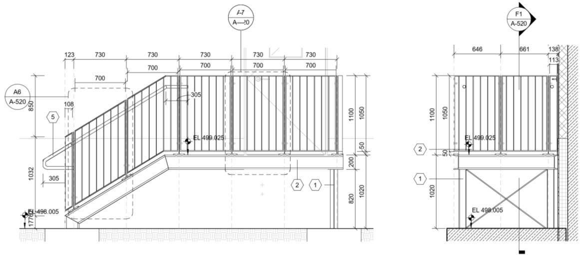
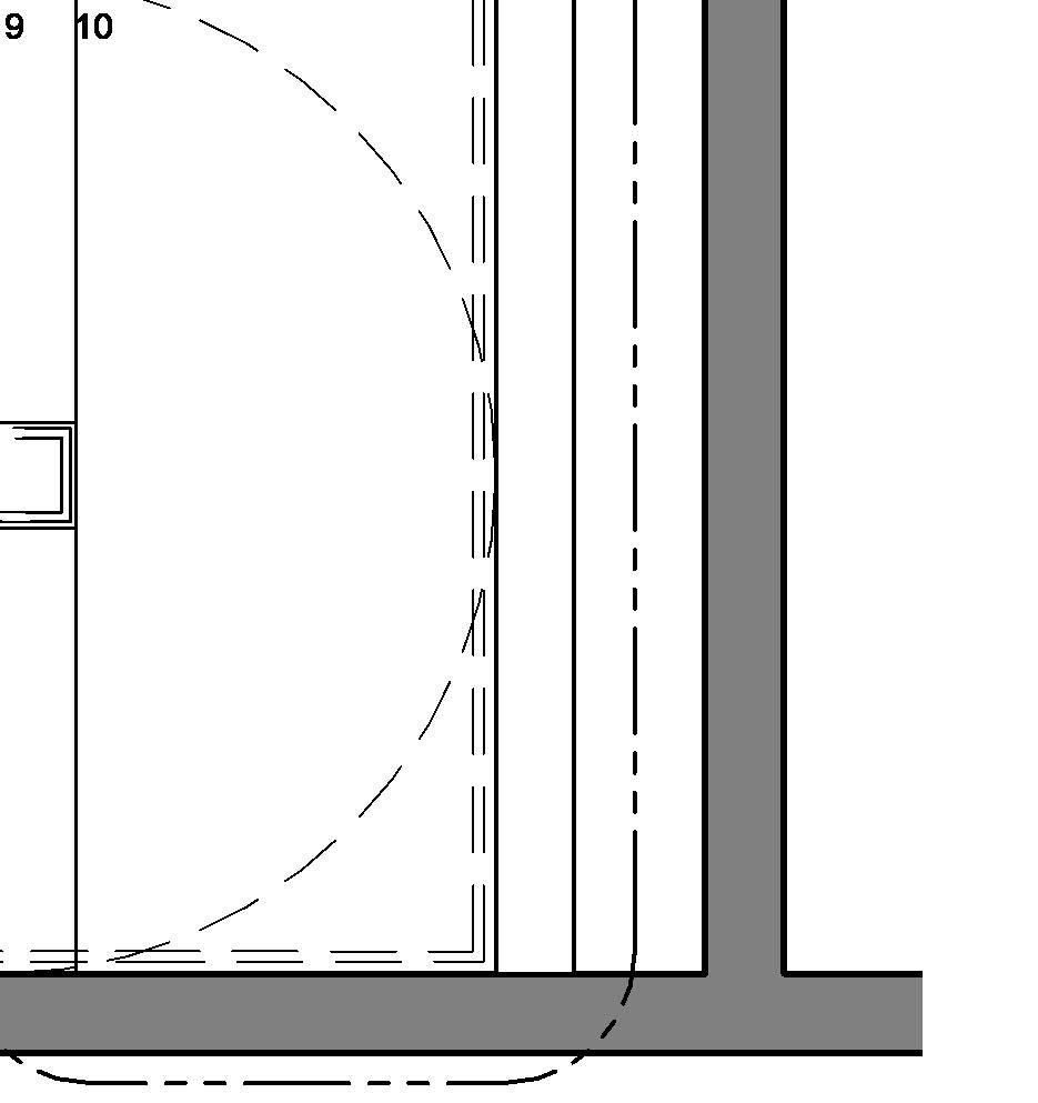
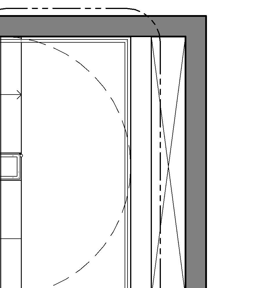
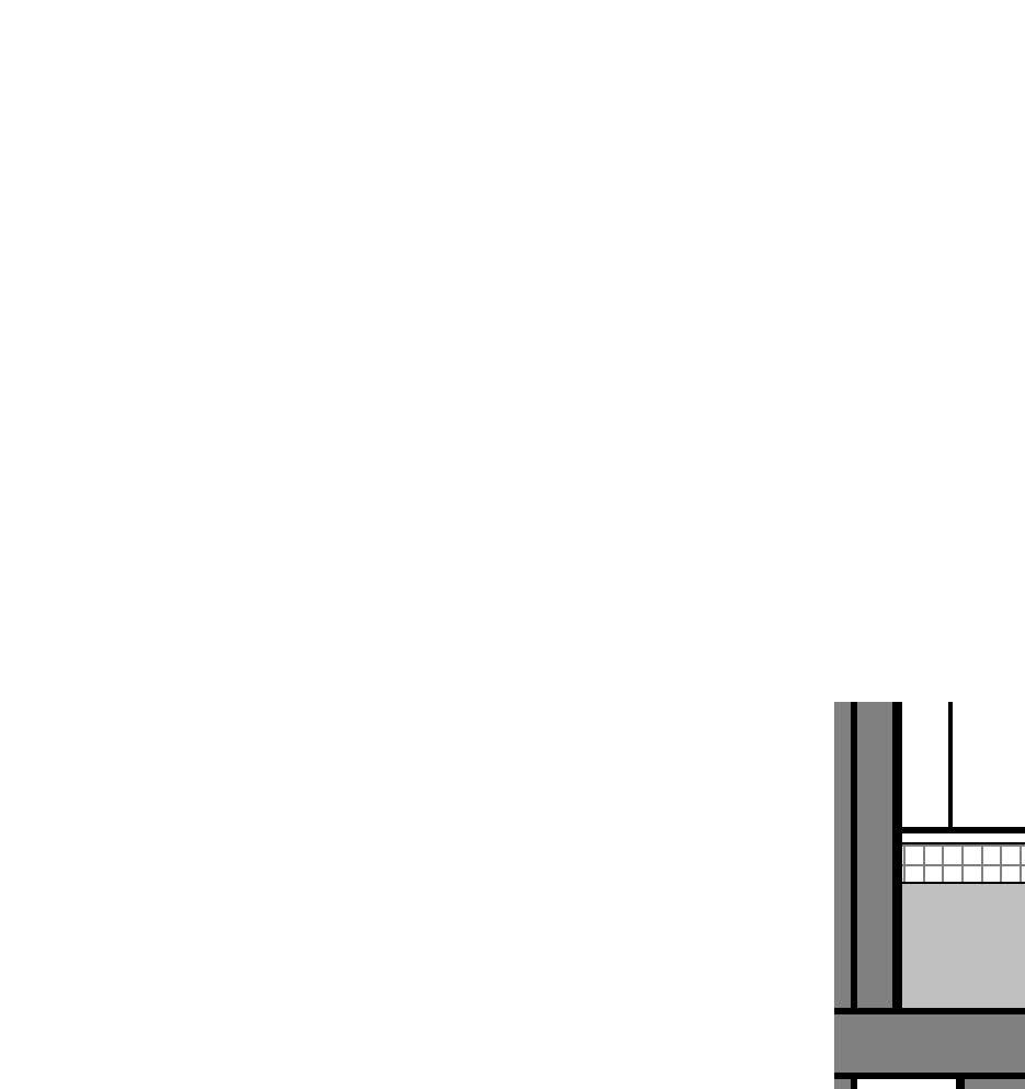
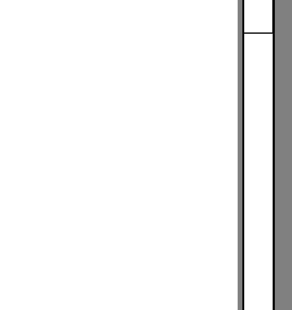
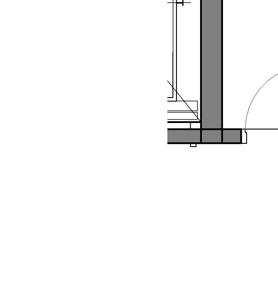
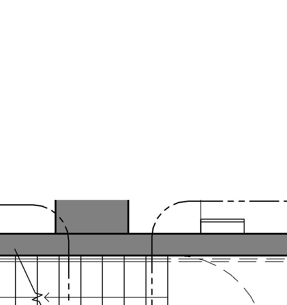
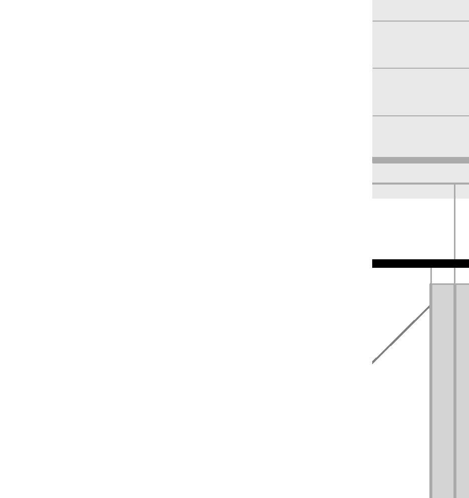
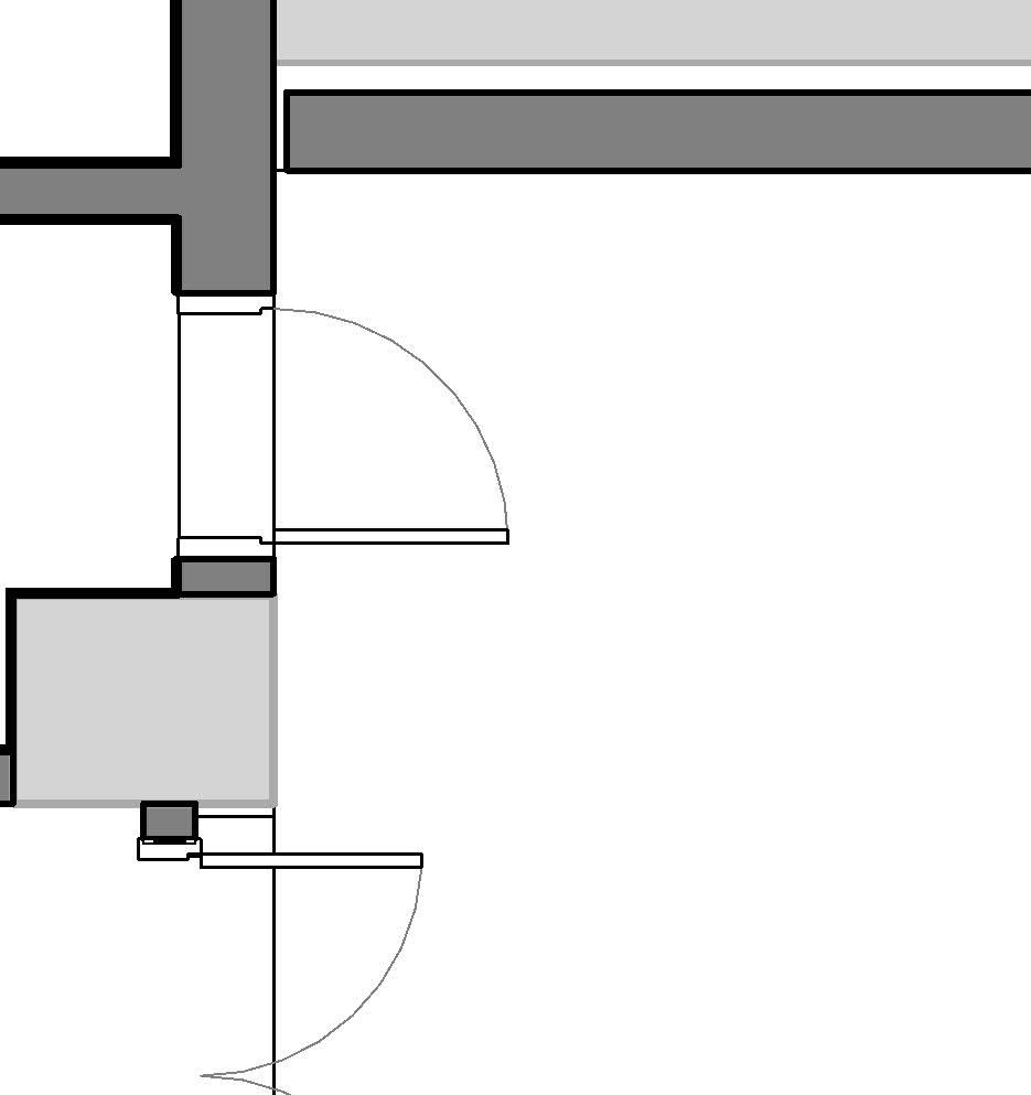
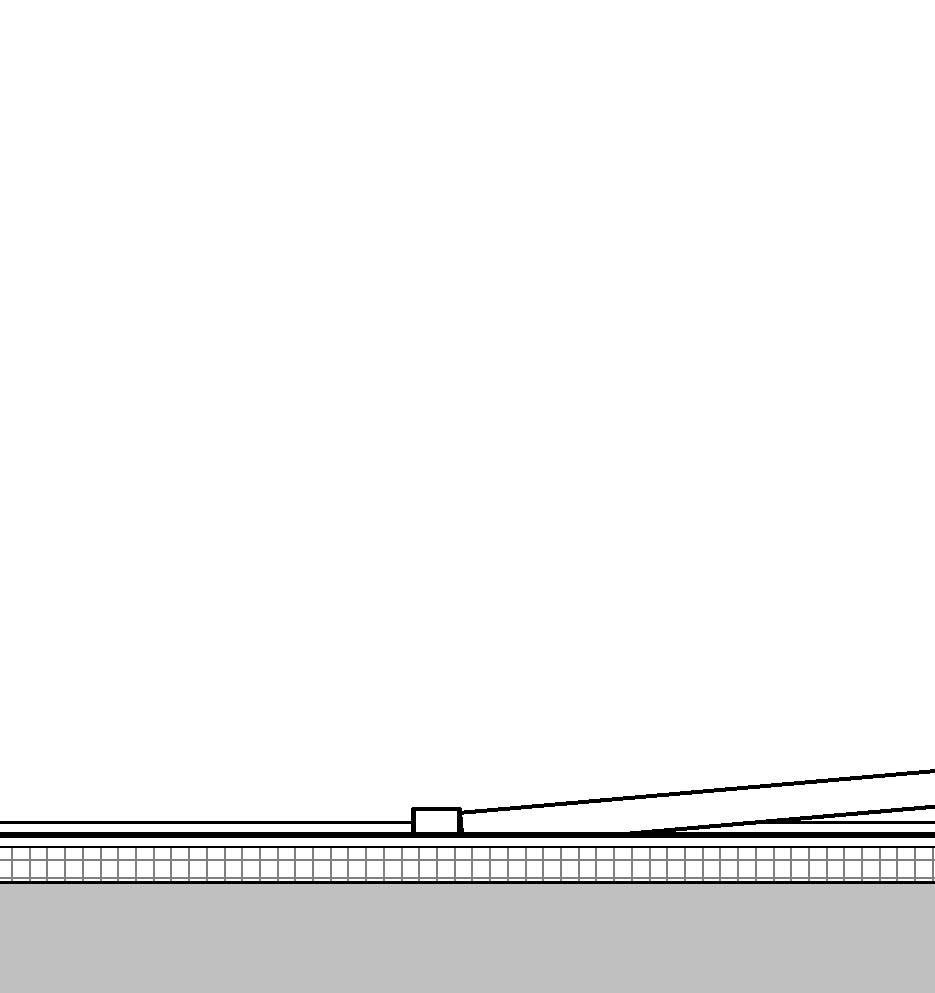
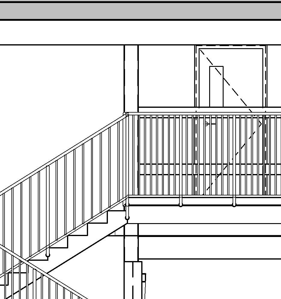
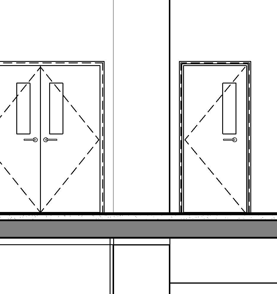
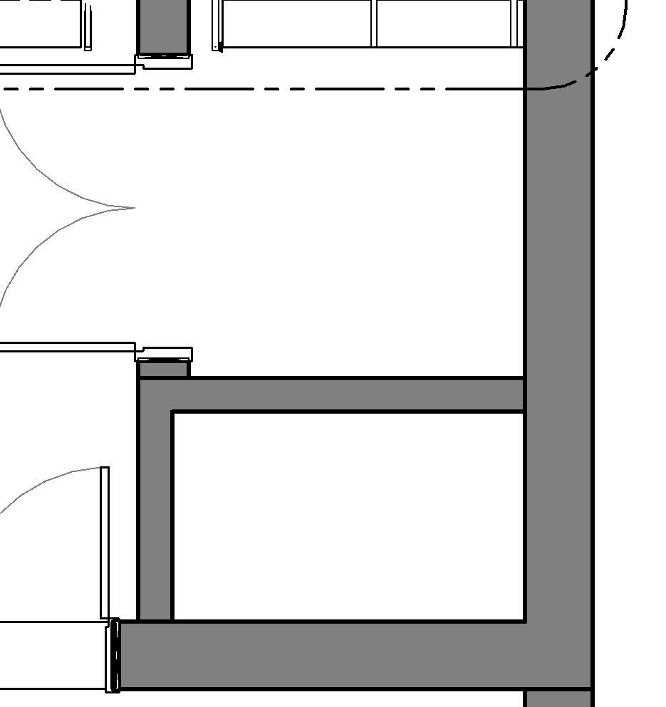
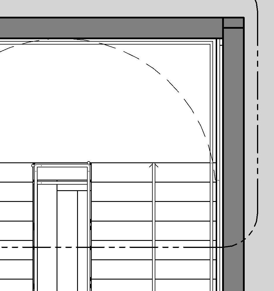
Elevations and plans at 1:50→
* Find these examples’ full documentation in chapter 09
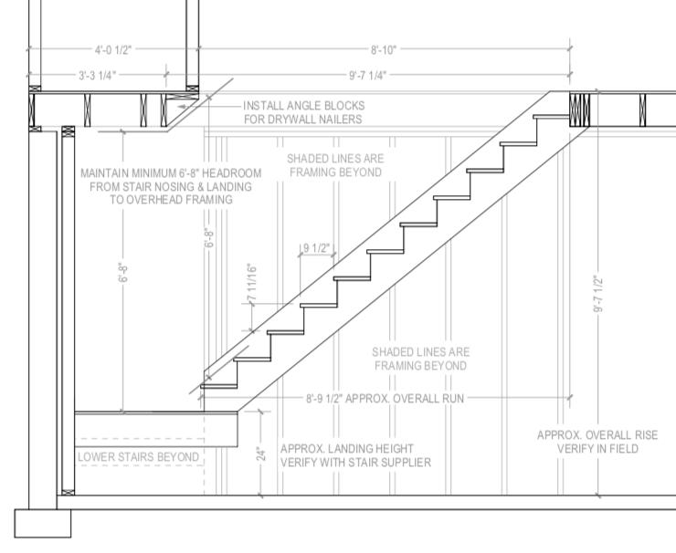
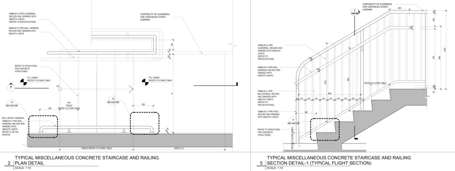
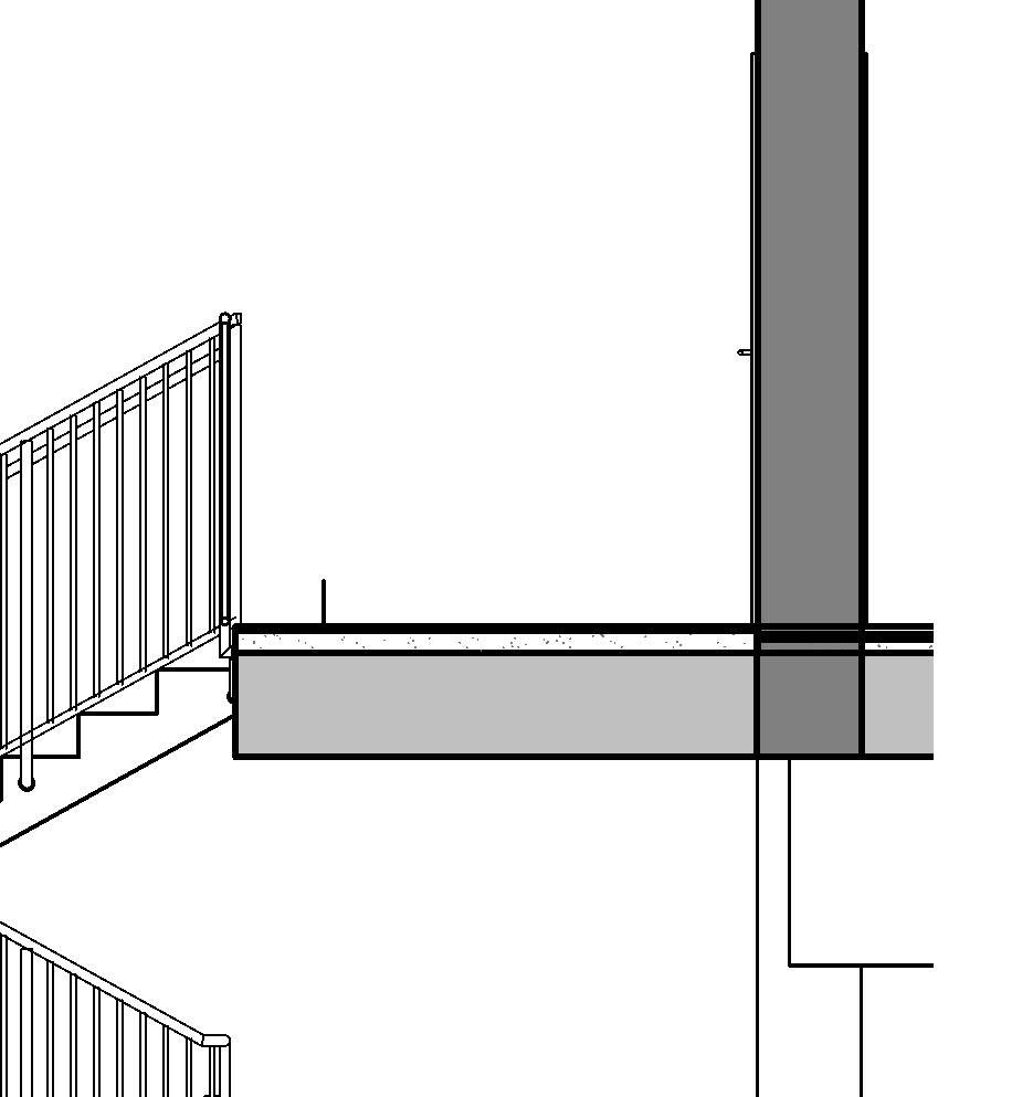
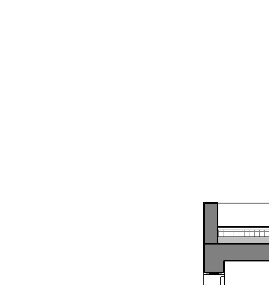
• Purpose: define at a construction level all the elements that compose the stairs
• Type of drawing: details in plan, section and elevation
• Usual scales: from 1:20 to 1:2
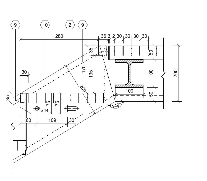
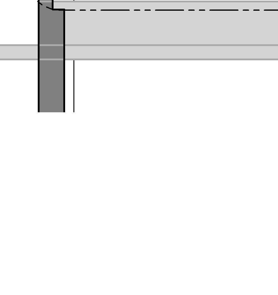
• Level of detailing: maximum, which includes tags and all required dimensions of all elements of the stair, including anchoring (bolts or similar), railing, stringer, etc.
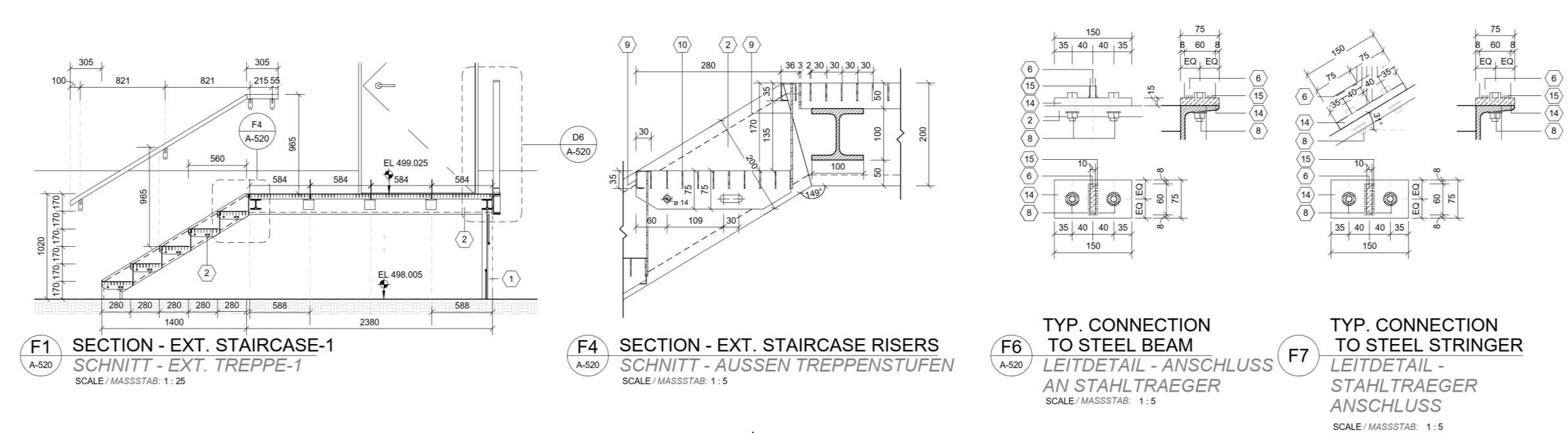
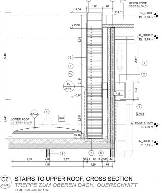
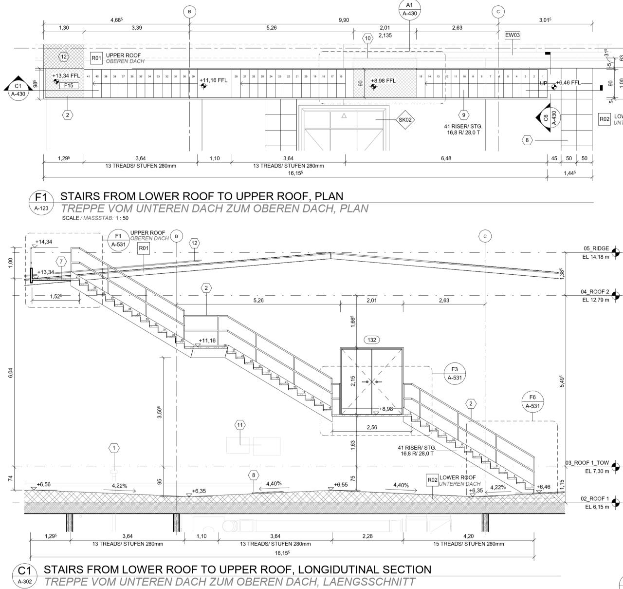
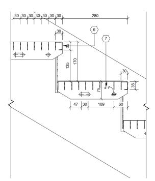
↑Section and plan details at 1:25 and 1:5
* Find these examples’ full documentation in chapter 09
• Purpose: define at a construction level all the elements that compose the stairs
• Type of drawing: details in plan, section and elevation
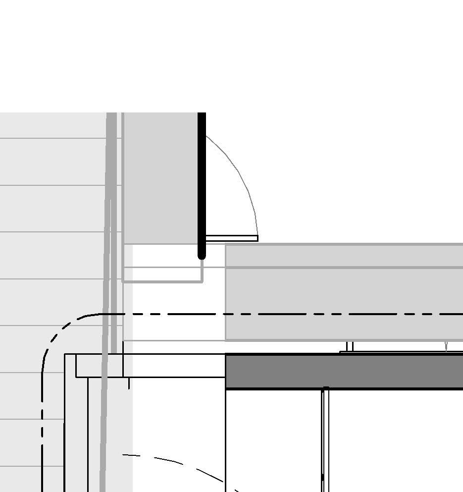
• Usual scales: from 1:20 to 1:2
• Level of detailing: maximum, which includes tags and all required dimensions of all elements of the stair, including anchoring (bolts or similar), railing, stringer, etc. ←Section details at 1:10 1:5, 1:2 and 1:1
* Find these examples’ full documentation in chapter 09
how to find the stairs in my project
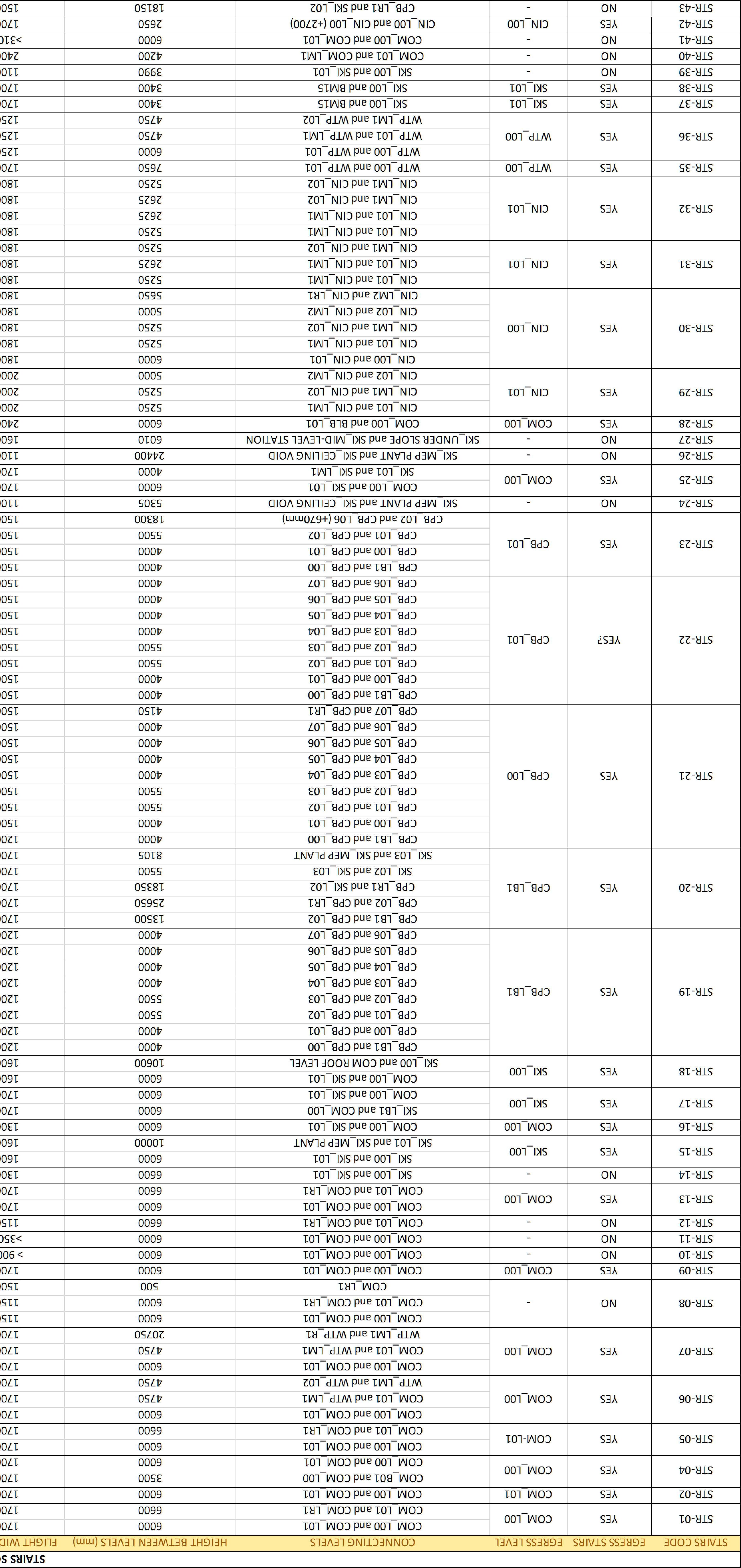
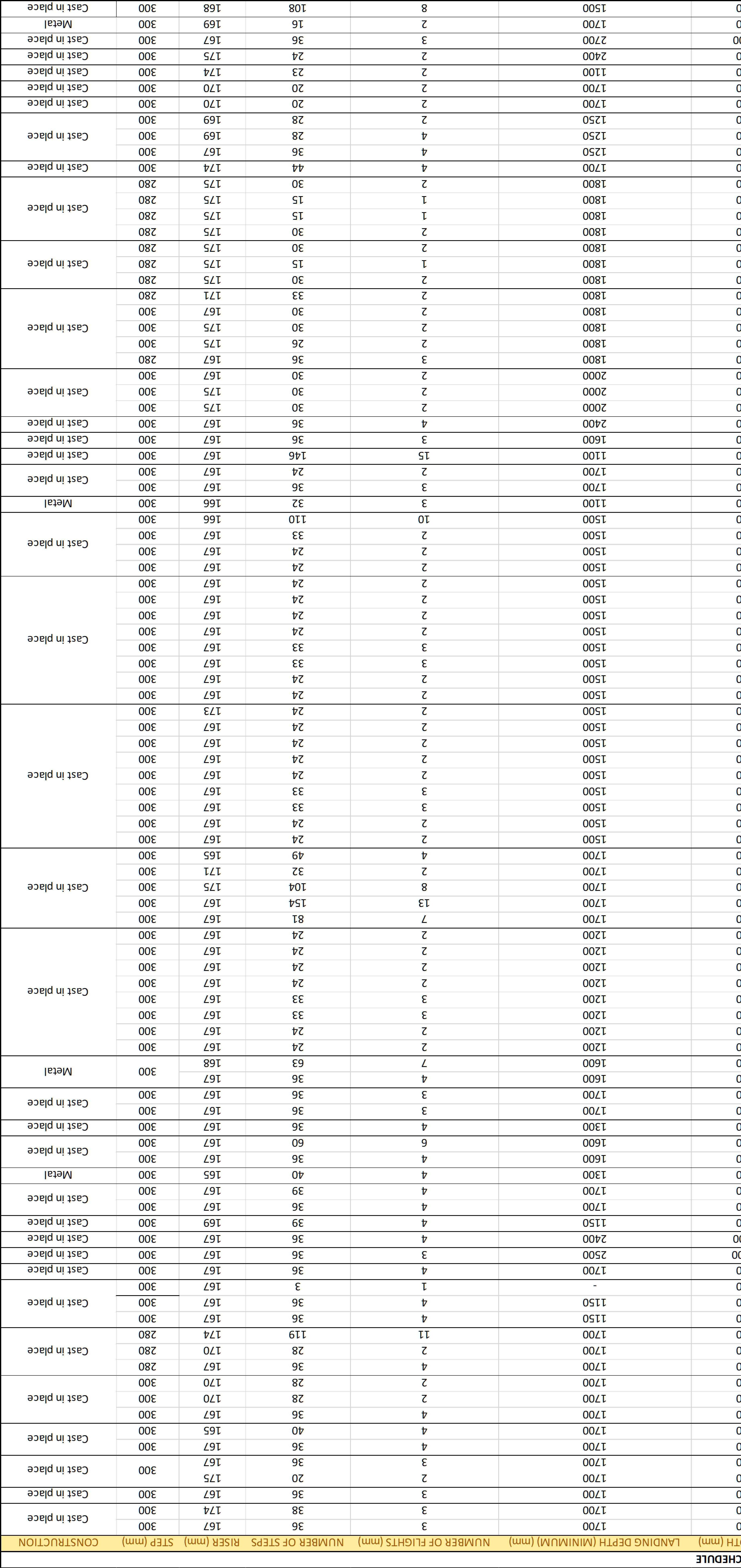
3.4 Fourth level of information, complementary to all previous 3 levels
• Purpose: to get an overview of all of the vertical transportation in a project and their parameters.
• Type of drawing: schedule* • Usual scales: N/A
*Not all projects may include a Stairs schedule or a Vertical Transportation Schedule. In projects with few stair cores, it may be deemed not necessary.
• Level of detailing: depending on the schedule may contain more or less information. It usually contains key planning dimensions, the type of construction, along with location of all vertical transportation cores, connecting levels, etc.

Example of a large project with a lot of stair cores, where it was fundamental to bring together the information of all of them in a readable format.
* Find these examples’ full documentation in chapter 09
The riser is the vertical component between two consecutive treads in a stairway, forming the upward face of each step. It determines the height a user must lift their foot to move from one tread to the next and plays a critical role in the geometry and safety of the stair.
Key Characteristics of a Riser:
• Measured vertically from the top of one tread to the top of the next.
• The height of the riser, in combination with the tread depth, defines the pitch (or slope) of the stair.
The Blondel formula: 2r + t = 63 cm is a rule of thumb commonly used in stair design. It is not part of the International Building Code (IBC). However, some European regulations, such as the Architectural Norm in France, or the UNI 10804 in Italy do include it, and Spain’s and Germany’s DIN18065 imply or are aligned to it too.
Standard Riser Dimensions:
• Commercial Stairs (IBC – International Building Code):
o Maximum riser height: 178 mm
o Minimum riser height: 102 mm
o Uniformity tolerance: The greatest riser height shall not exceed the smallest by more than 9.5 mm
• Can be solid (closed riser) or open, depending on the design and code requirements.
• Must be uniform throughout a flight of stairs, with minimal variation to prevent tripping.
Tolerances: Even small variations in riser height can trip people up, especially those with mobility issues. That’s why uniformity is just as important as meeting max/min height requirements.
• Residential Stairs (IRC – International Residential Code):
o Maximum riser height: 197 mm
o Minimum riser height: No specific minimum, but typically not less than 100 mm for usability
o Uniformity tolerance: No more than 9.5 mm difference between the tallest and shortest riser
Measured vertically from the top of one tread to the top of the next.
Riser’s key planning dimensions:
Floor to floor height *
Floor to landing height
* Use the floor-to-floor height and the agreed possible riser heights to divide and obtain the number of risers.
Number of risers *
Full riser height
A tread is the horizontal component of a stair on which the foot is placed during ascent or descent. It extends from the front edge (nosing) to the back edge and is a key factor in determining the stair’s slope, comfort, and safety.
Key Characteristics of a Tread:
• Measured horizontally from nosing to nosing (in code-compliant stairs).
• Works in conjunction with the riser to define the stair geometry.
• Must be uniform in depth across all steps within a stair flight to avoid tripping hazards.
• Can include a nosing projection—the portion of the tread that extends beyond the face of the riser (or imaginary riser in open stairs).
Tolerances
Standard Tread Dimensions:
• Commercial Stairs (IBC – International Building Code):
o Minimum tread depth: 279 mm, measured nosing to nosing
o Uniformity tolerance: Tread depth variation shall not exceed 9.5 mm between the largest and smallest tread in a single flight
Treads with nosing
• Residential Stairs (IRC – International Residential Code):
o Minimum tread depth: 254 mm
o Tread depth can include a nosing projection of 19mm to 32mm if the tread is less than 279mm deep
o Uniformity tolerance: Same as commercial – no more than 9.5 mm variation
• A consistent tread depth is critical to prevent trips and ensure user confidence.
• For stairs without risers (open riser stairs), the treads must still meet the depth requirements
• Where nosings are used, they should be:
o Consistent in projection within a flight (± 9.5mm)
o Beveled or rounded to reduce injury risk
Treads without nosing
Measured horizontally from nosing to nosing
Tread’s key planning dimensions:
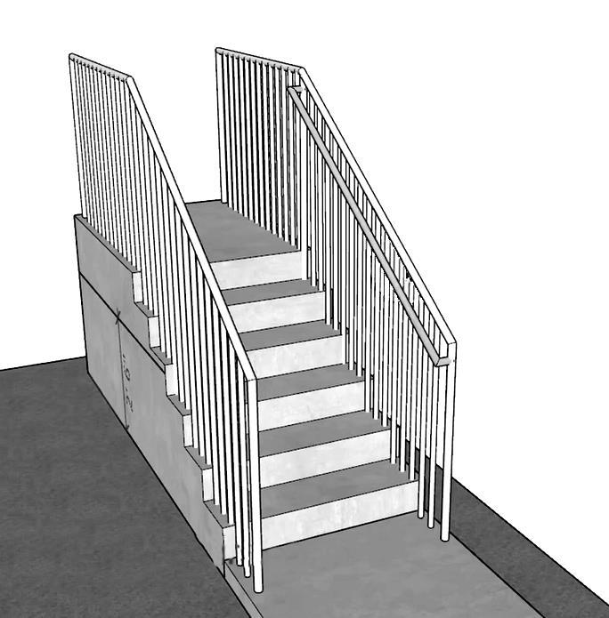
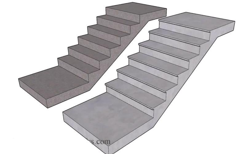
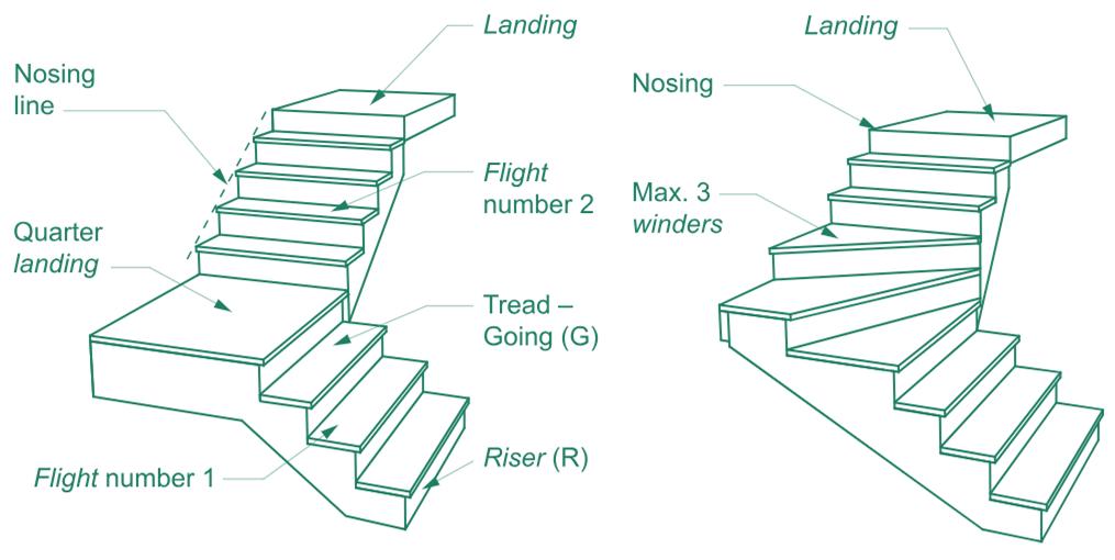
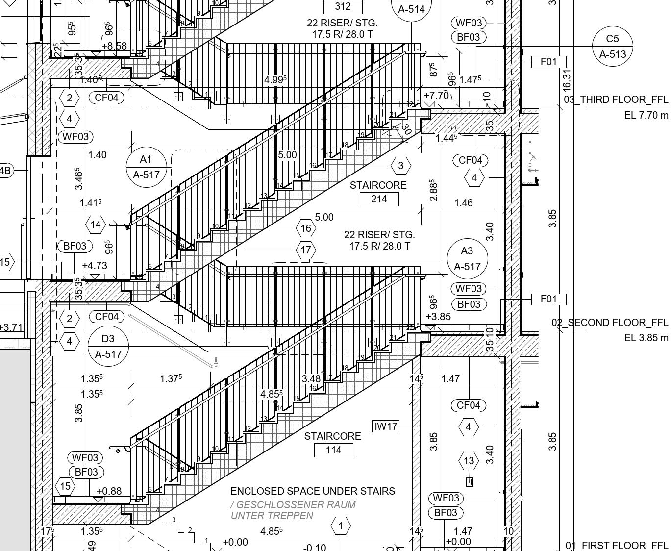
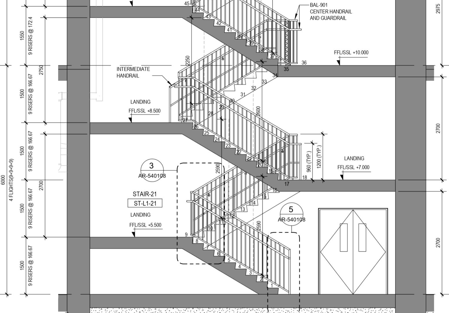
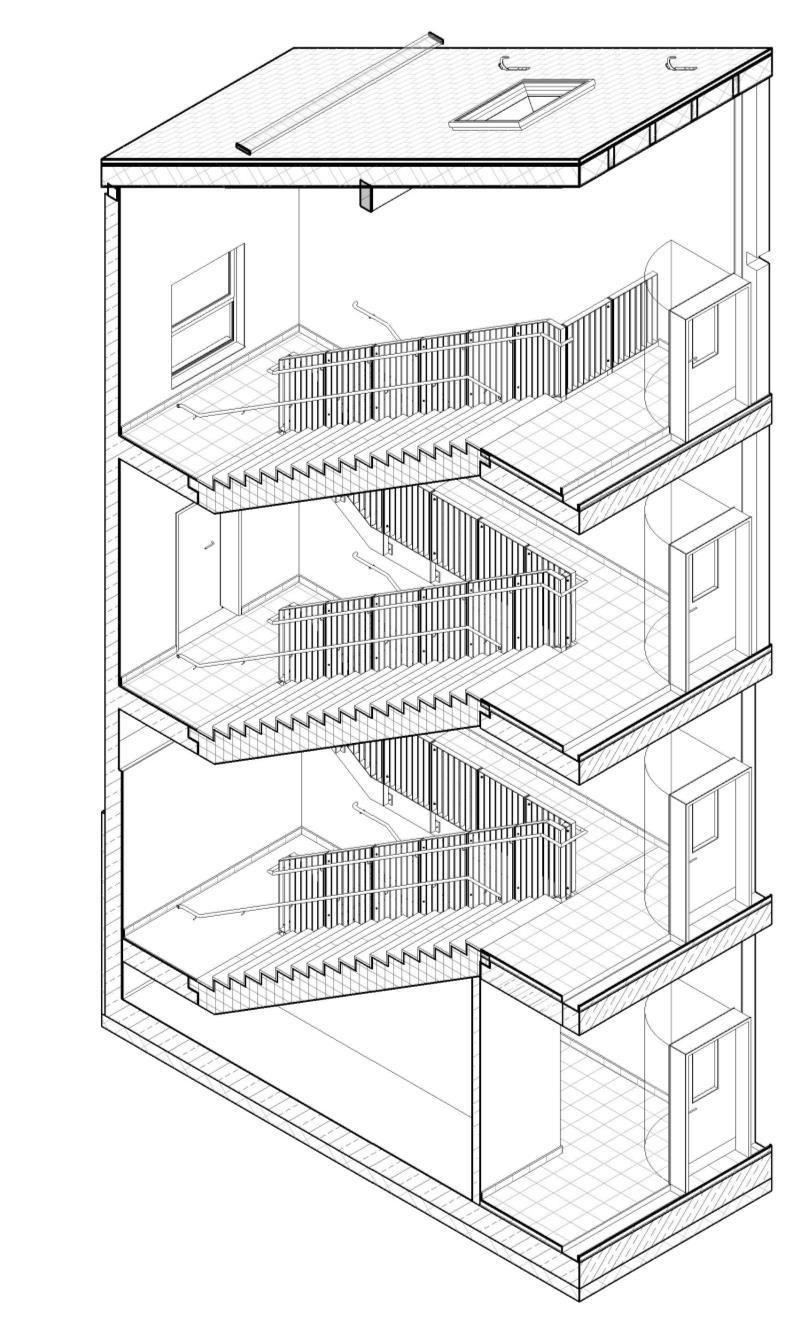
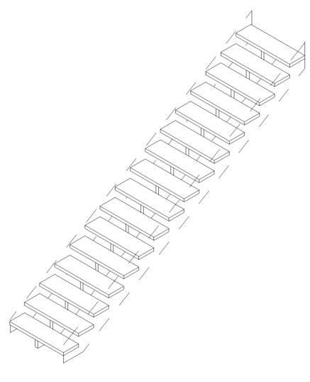
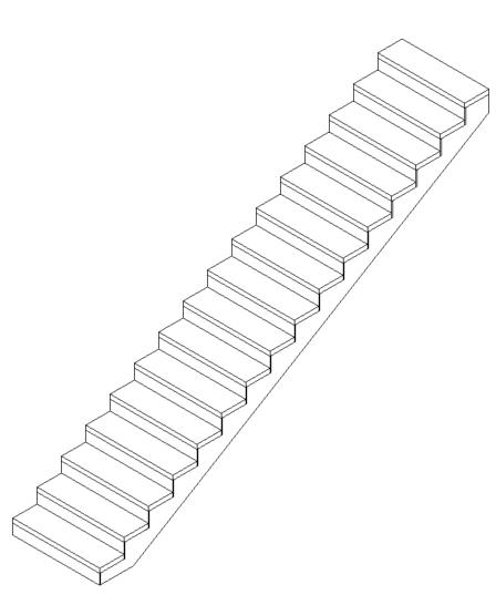
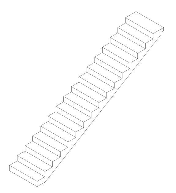
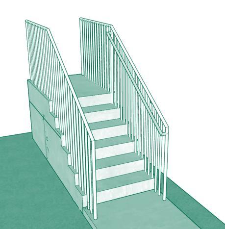
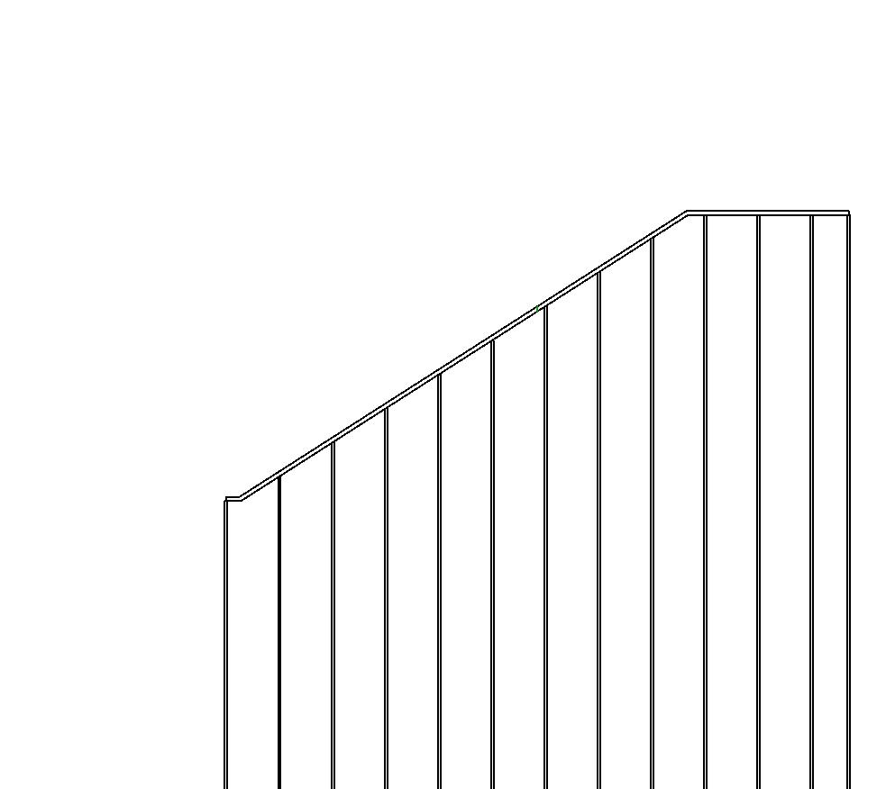
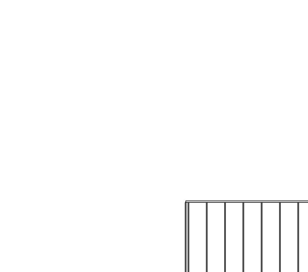
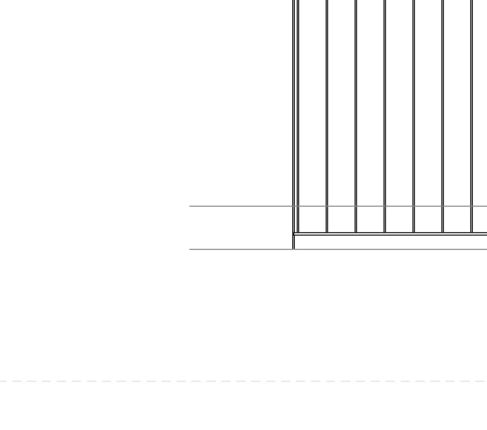
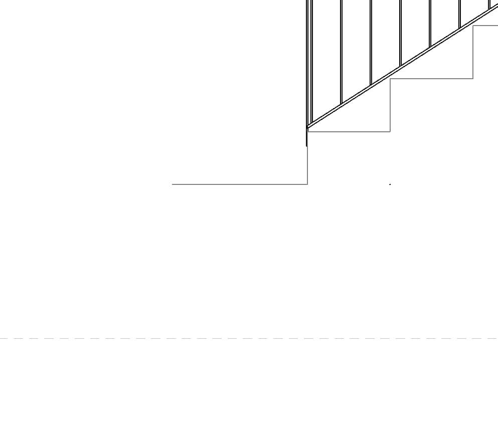
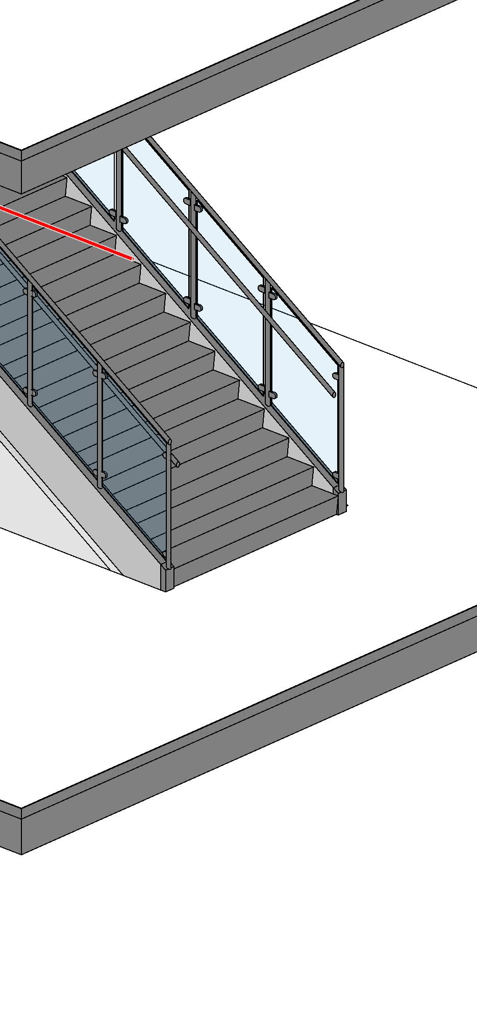
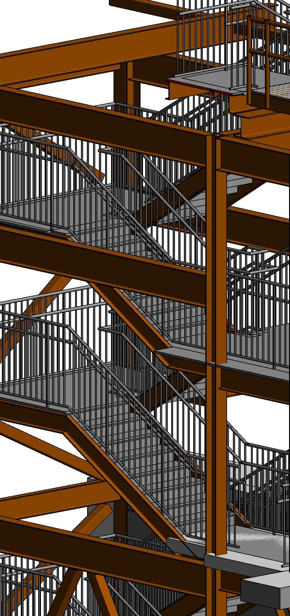
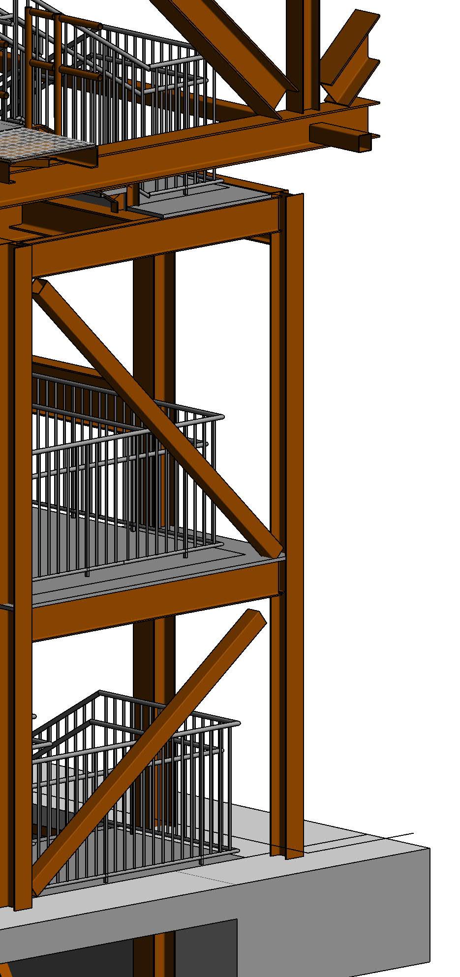
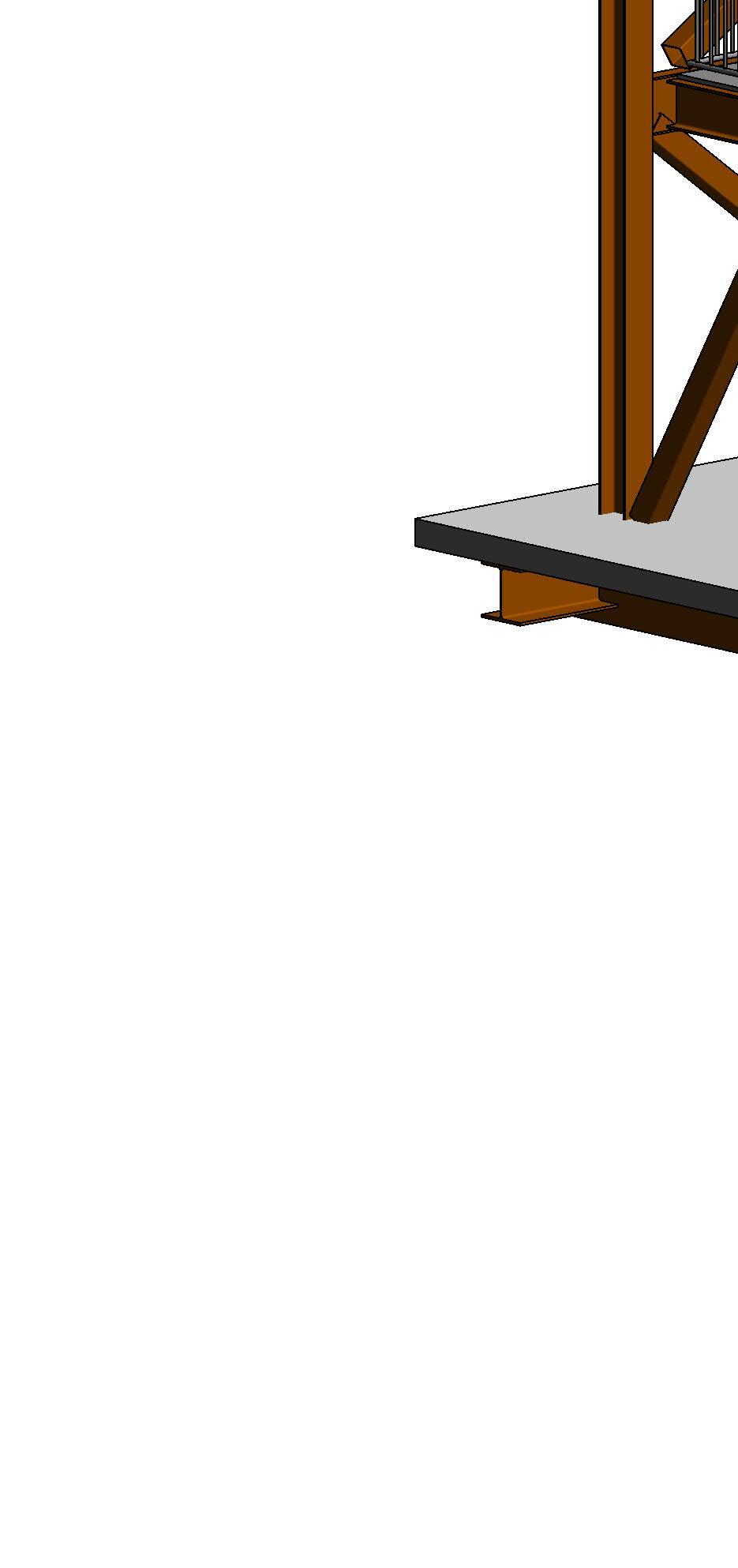
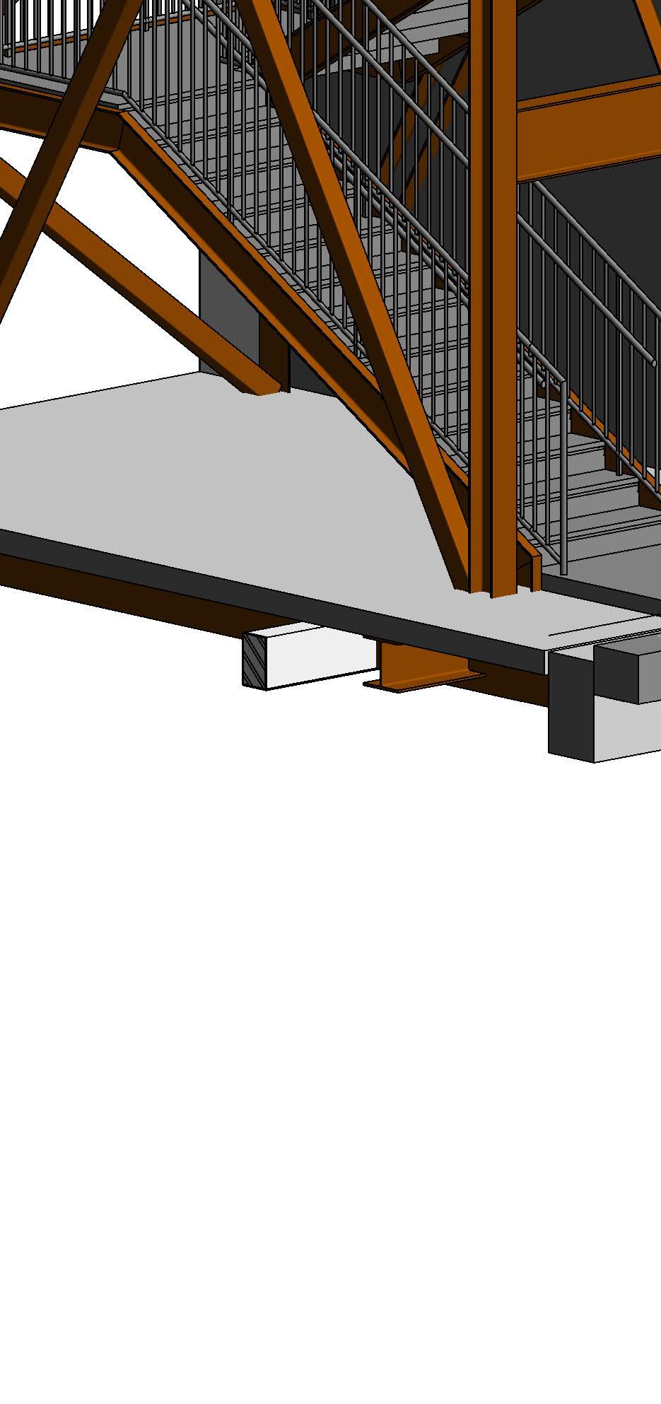
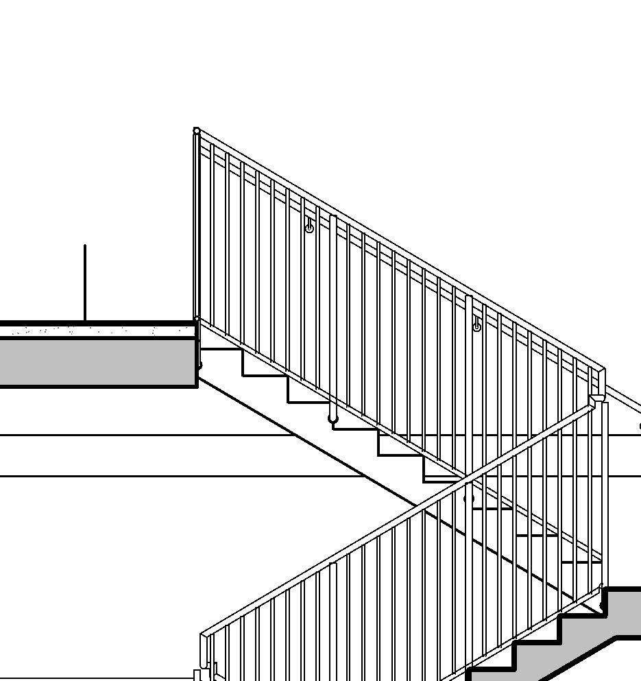
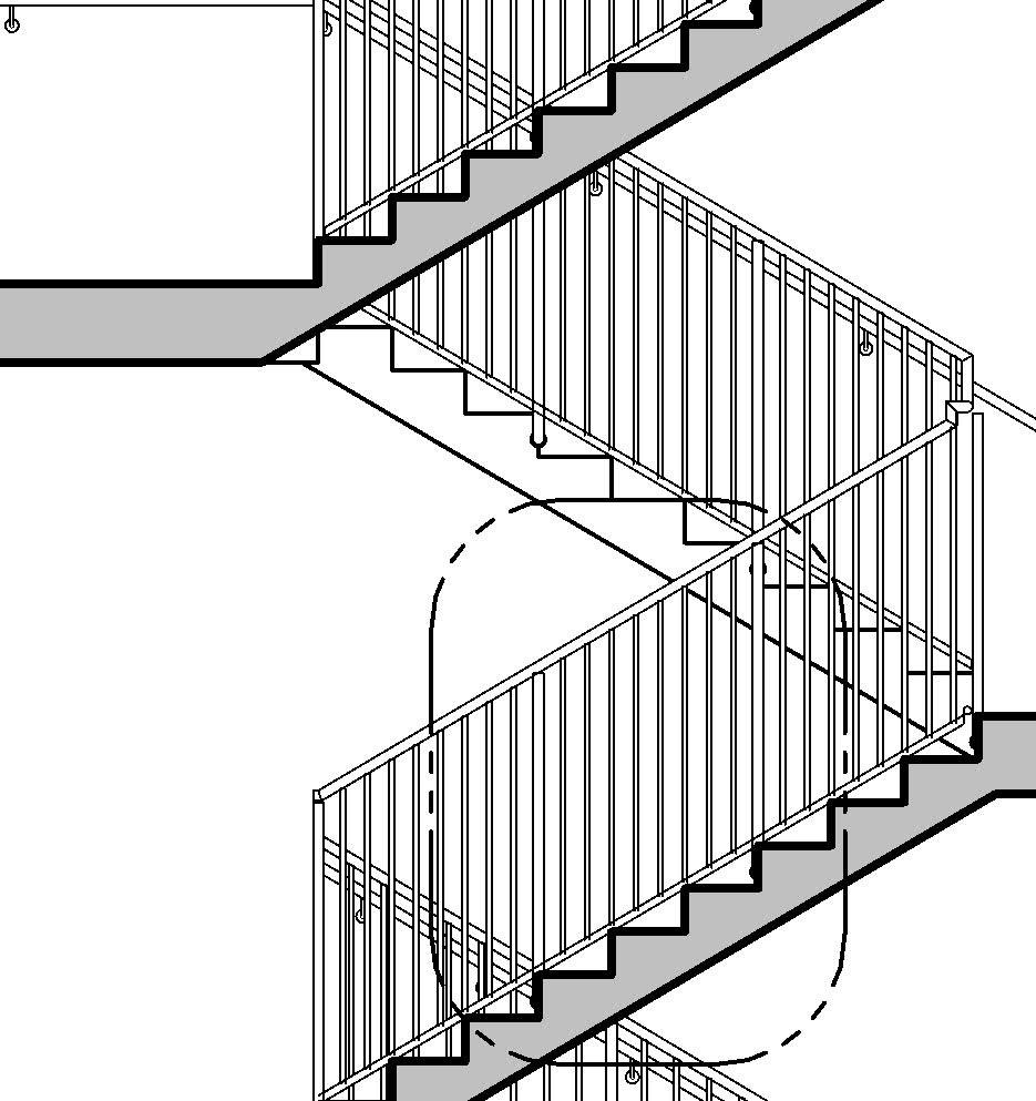
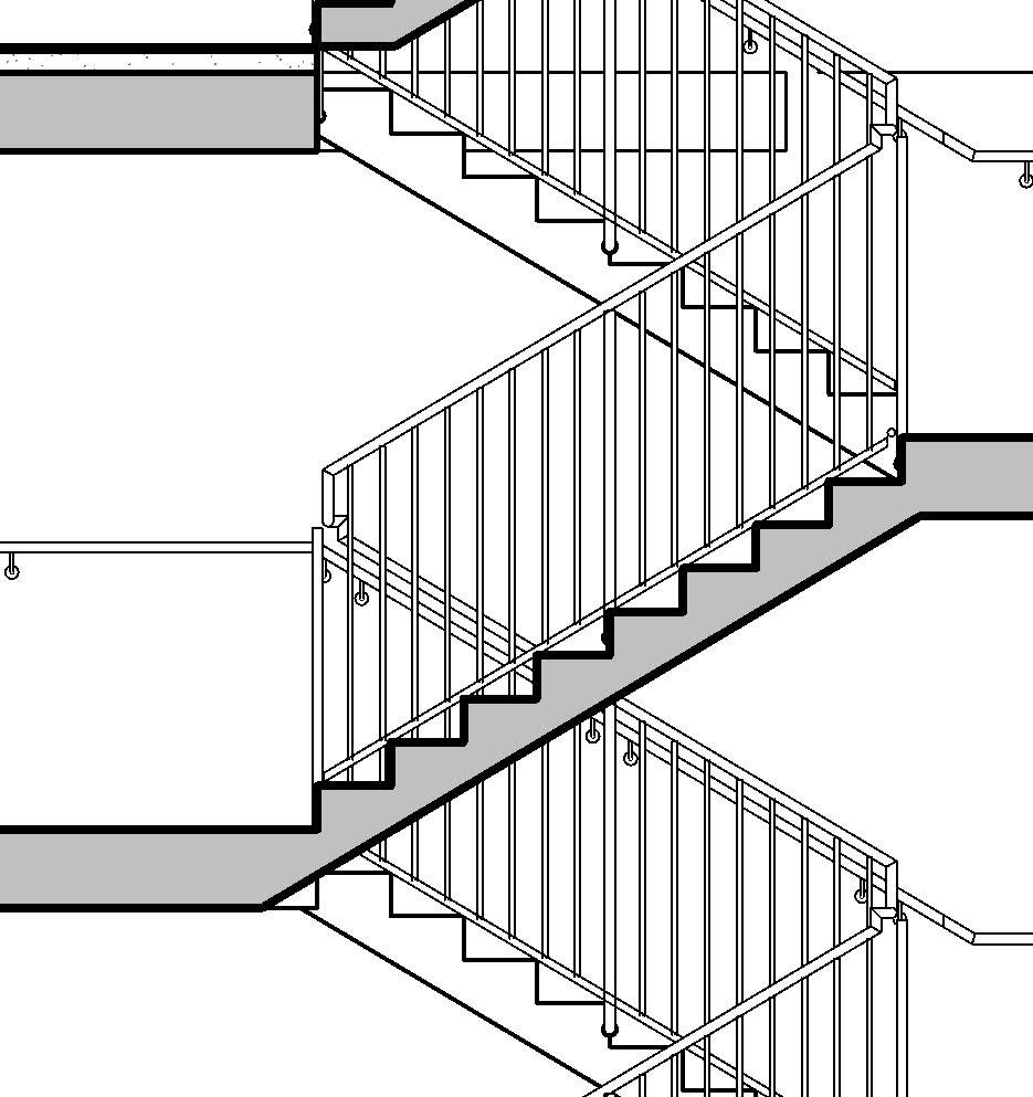
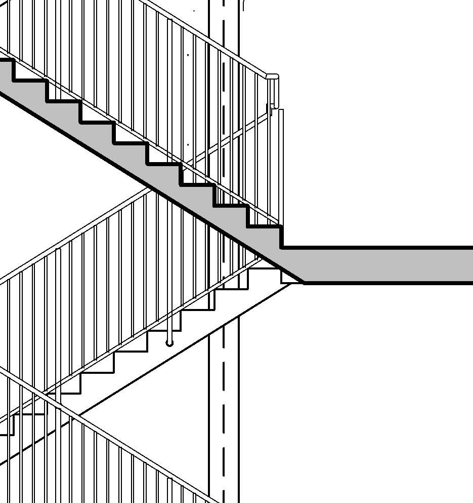
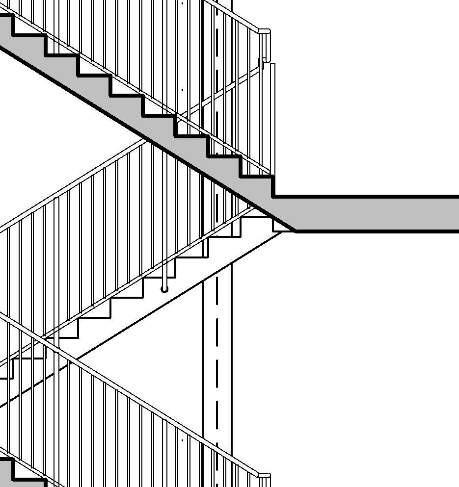
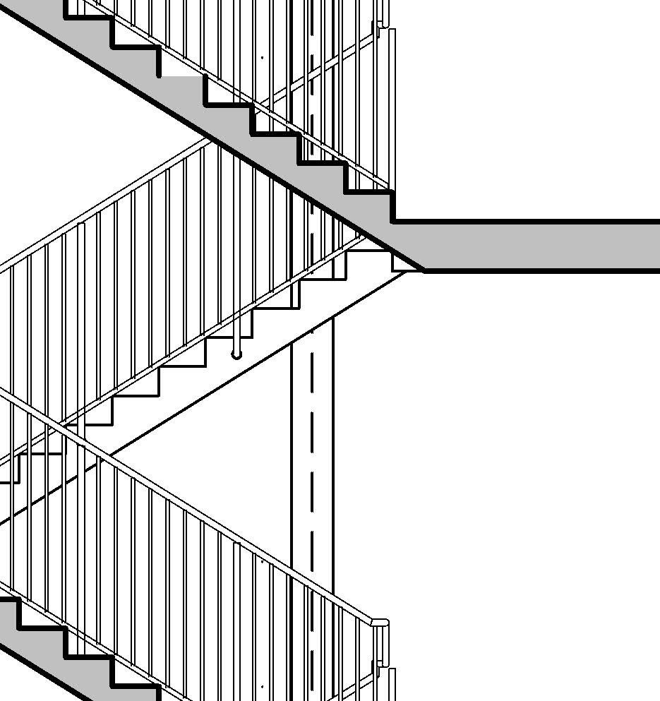
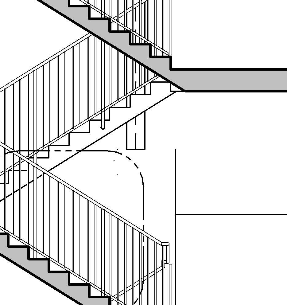
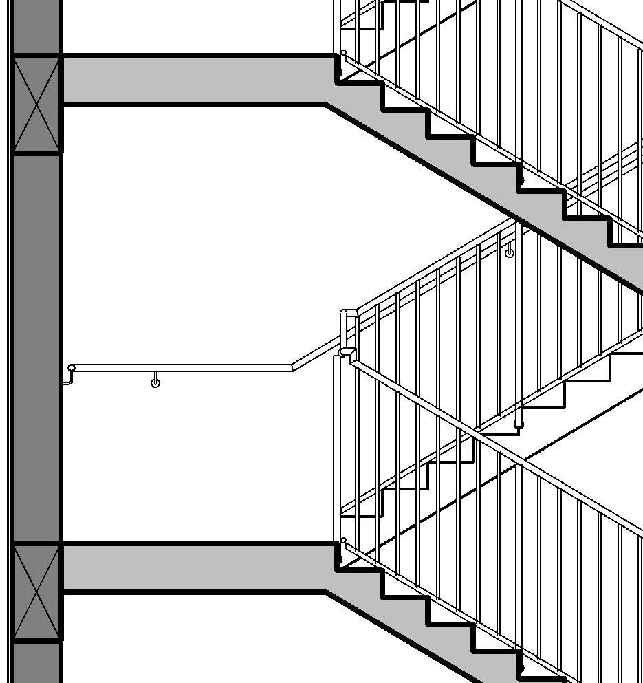
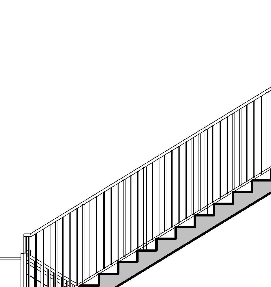
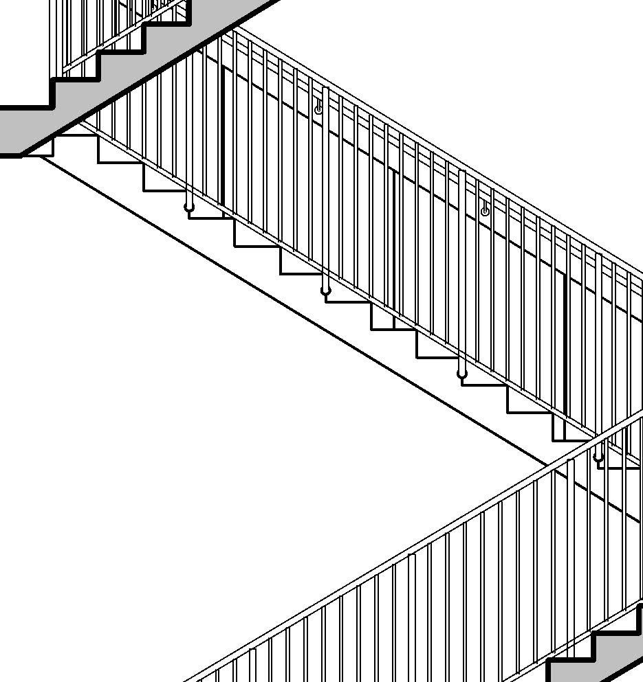
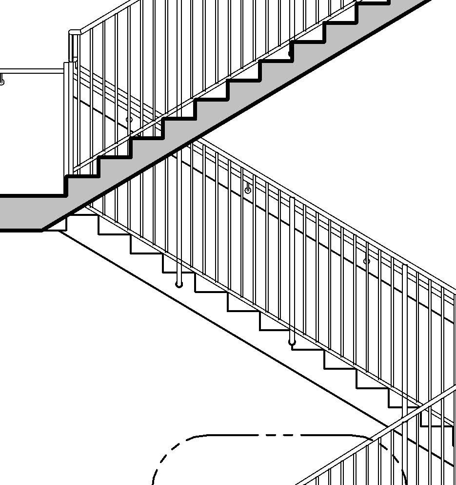
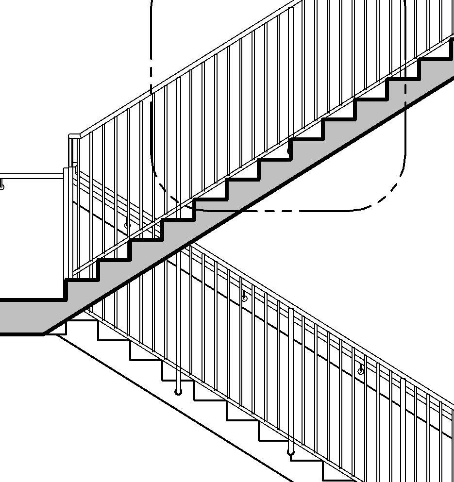
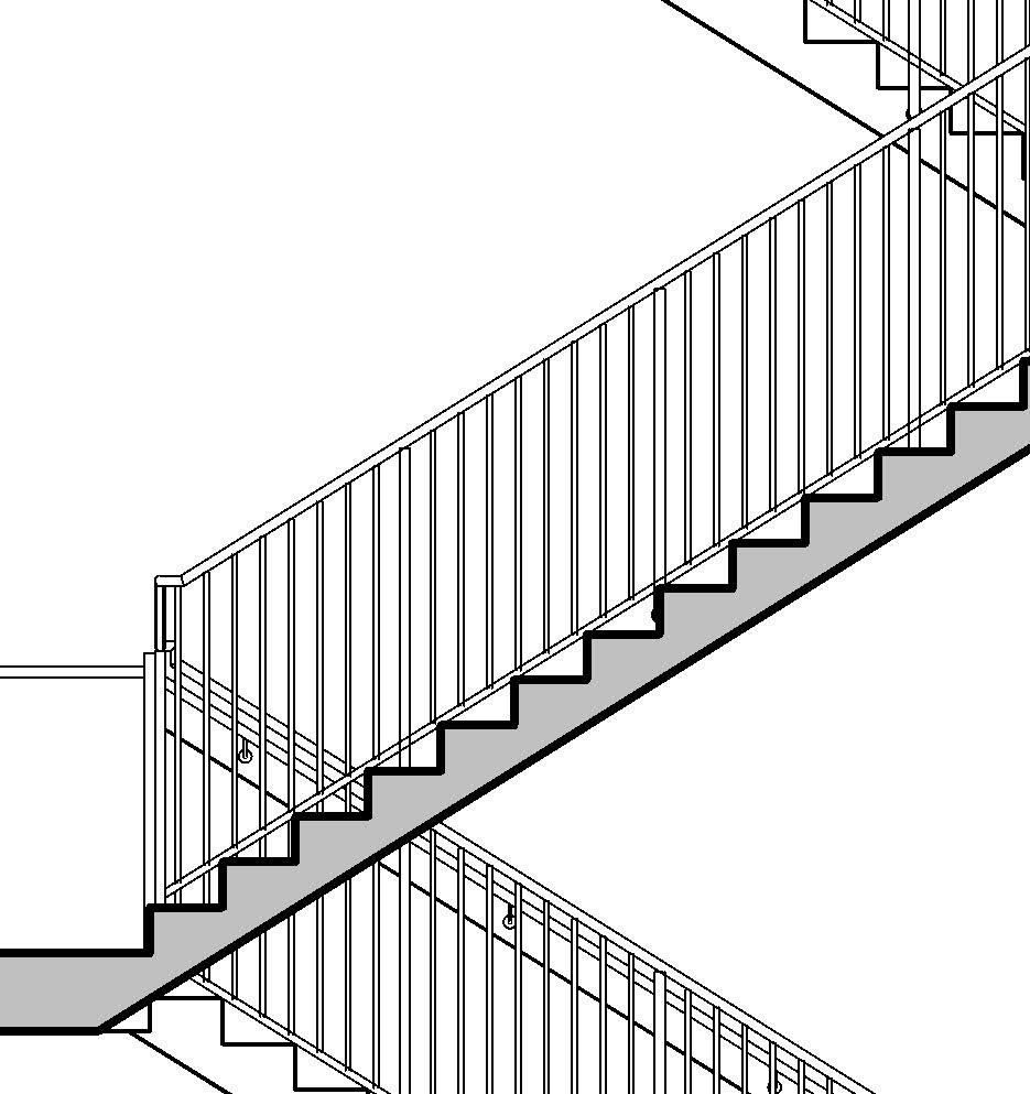
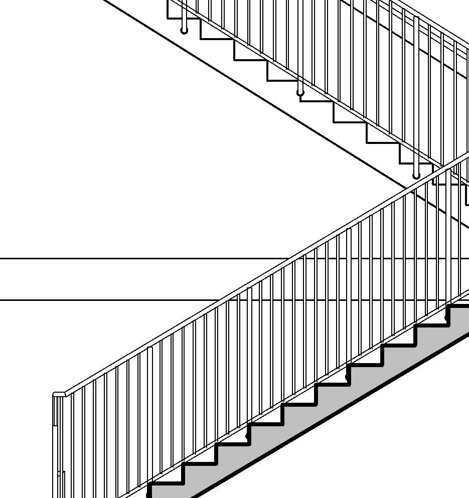
Staggered flights of stairs like this one are offset or interlaced stairways that share vertical space efficiently. The are commonly used in compact architectural layouts or split-level designs.
This configuration allows for spacesaving without compromising functionality, and it avoids central railing extensions. This way the overall length of the staircase is reduced. Despite the layout, all standard building code requirements for stairs still apply.
* To obtain the number of treads use the available flight length and the agreed tread depth to divide and obtain the number of treads, but also consider: number of flights, floor to floor distance, maximum riser height (as per codes), formula compliance (if any is required by codes), round height for risers, etc
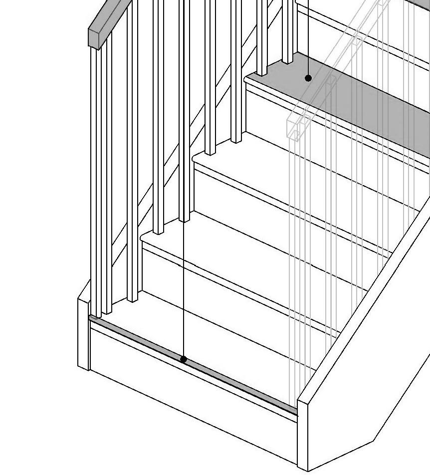
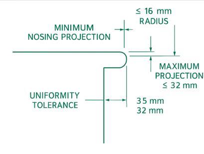
The nosing is the leading edge of a stair tread that projects beyond the face of the riser (or the tread below, in open riser stairs). It improves footing and stair visibility and protects the corners from impacts.
Key Characteristics of a Nosing:
• Required when tread depth is less than 279 mm. Not required for tread depths ≥ 279 mm.
• Nosing must be uniform across the flight of stairs.
• Can be beveled or rounded, but with restrictions on how sharp or deep the curve is for safety
• Nosings should not create a trip hazard— meaning they should be either rounded, beveled ≤ 30°, or have a consistent shape.
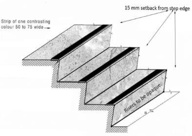
• Some codes prefer contrasting nosing (visually) for better visibility in public/commercial buildings.

Standard Nosing Dimensions:
Parameter Standard Value Minimum
Anti-slip strips
According to ICC A117.1-2017, Section 504.4.1–(Accessible and Usable Buildings and Facilities), some buildings such as Government buildings, public transit and schools and public facilities require visual contrast on stair nosings for accessible stairs.
Other regulations, such as the UK Building Regulations (Approved Document K & M), explicitly require anti-slip nosings in public and educational buildings, as well as tread edges to be distinguishable to aid visually impaired users.
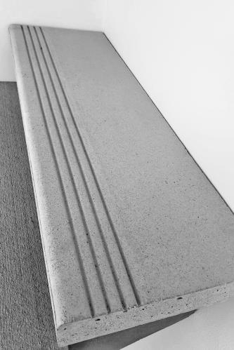
In precast concrete stairs, the anti-slip strip is an integrated part of the precast element.
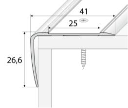
Nosing, the leading edge of a stair tread that projects beyond the face of the riser
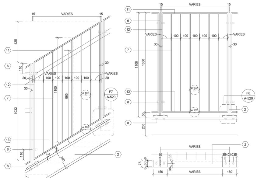
A stringer is the inclined structural member that supports the treads and risers of a stair. It runs along the side(s) or center of the stair and may be cut (open) or closed (housed) depending on design.
Key Characteristics of a Stringer:
Depth (Height of Stringer):
• Typically 250 mm to 300 mm deep at the deepest point (bottom of tread to top of riser) in residential wood stairs.
• Larger depth or reinforcement is required for longer spans or heavier loads (e.g., commercial/industrial stairs).
• At least two stringers are required, typically three or more for wider stairs.
Material & Thickness
• Wood (residential): 38 mm to 50 mm; Usually 2x12 nominal lumber (actual: ~38×286 mm)
• Steel stringers: thickness varies by design; Channel or tube steel; depends on load and span
• Concrete stringers: thickness as designed; Often formed as part of the slab or wall; dimensions are structural
• Steel and concrete stairs usually follow an engineered design with stringer dimensions based on span, occupancy load, and structural performance. Tolerances & Code Considerations:
• Stringer alignment: Must maintain uniform rise/run within ± 3 mm
• Cut stringer accuracy: Riser/tread cuts must be within ± 3 mm to avoid trip hazards
• Spacing of stringers: Typically 400 mm to 600 mm center-to-center for wood
• Load-bearing deflection: Per structural code (e.g., L/360 for live load deflection)
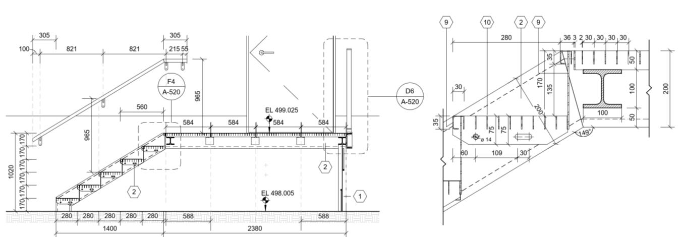
Example of elevation of a steel stringer
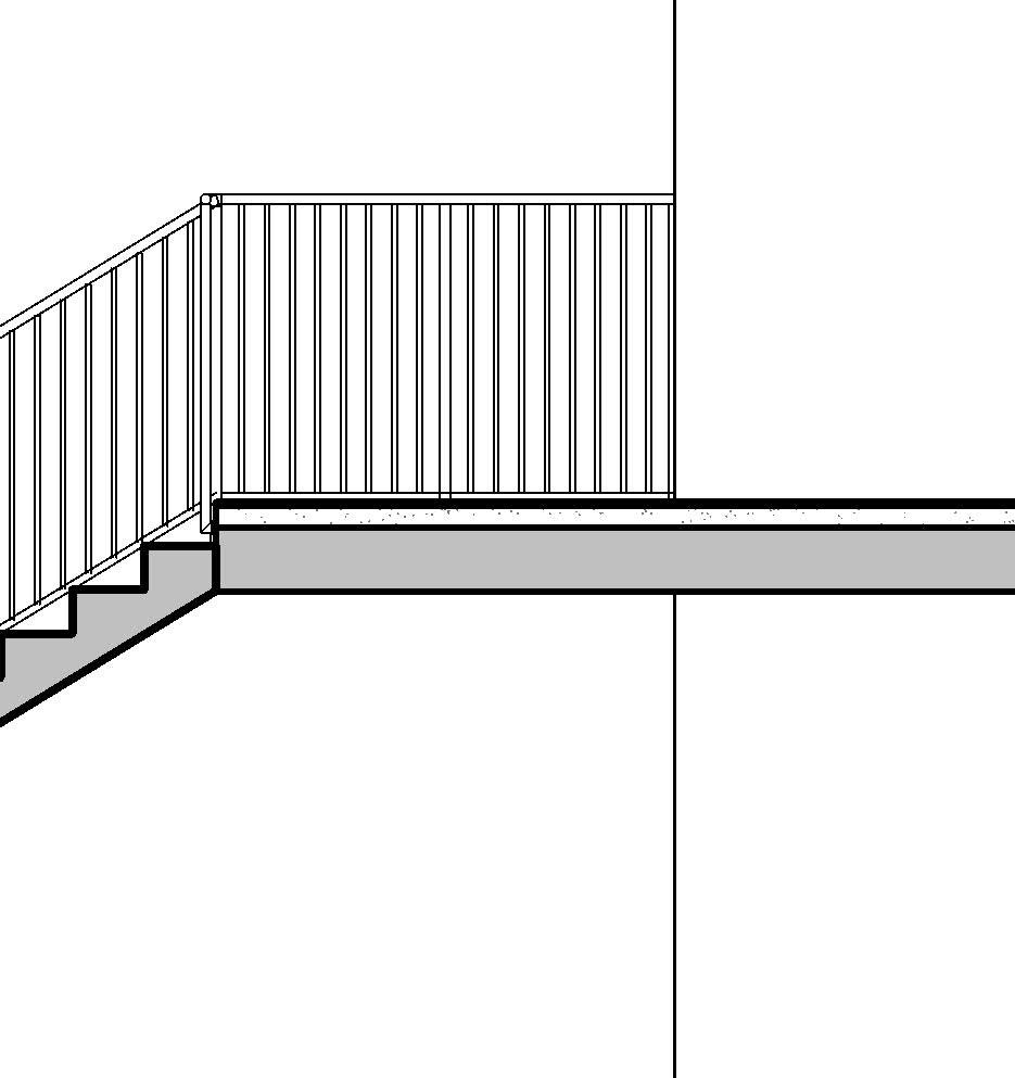
A landing is a horizontal platform or intermediate level between two flights of stairs, or at the top or bottom of a stairway, providing a resting point, directional change, or transition between levels. It is considered an integral part of the stair system for functionality, safety, and accessibility.
Key Characteristics of a Landing:
• Can be located:
o At the top or bottom of a stair flight
o Between two flights in multi-story or long stairs
o At direction changes (e.g., 90°, 180° turns)
• Must be level and stable
• Provides space for users to rest, turn, or redirect motion
Accessibility (ADA/IBC):
• Landings must be clear and unobstructed
• Must accommodate wheelchair turning space if at the top/bottom of accessible ramps or stairs
• Must be at least 1,220 mm deep if part of an accessible route
• Have a non-slip, stable surface
Standard Landing Dimensions (according to IBC/IRC):
• Depth (in direction of travel): Same as the stair width, typically ≥ 900 mm
• Width (perpendicular to travel): Must be ≥ width of the stair flight
• Maximum vertical rise without landing: 3,660 mm before a landing is required
• Minimum clear space on landing: ≥ 900 mm × 900 mm (residential)
Tolerances and Considerations
• Level surface: Must be uniformly level within construction tolerances
• Change in elevation (slopes): Maximum slope: 1:48 (2%) for accessibility compliance
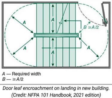
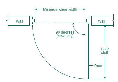
• Door encroachment: Swinging doors must not reduce the landing depth below minimum required
• Obstructions: Landings must be clear of obstructions unless otherwise allowed by code
• Landings may need to be enlarged to include an area of refuge, depending on building use and accessibility needs (IBC). These areas are designed to provide temporary protection for individuals who cannot use stairs during emergencies (e.g. wheelchair users).
• A mid-landing (intermediate platform) is required when a stair rises more than 3.66 m (12 ft) vertically (NFPA101).
Stair landing and clear width dimensions are influenced by Fire & Life Safety (FLS) analysis, particularly means of egress requirements set by building codes, not only the IBC, but also NFPA 101– Section 7.2.2.3.2 (Life Safety Code) and local fire codes. FLS analysis considers:
• Occupant load calculations per floor and exit route
• Travel distances and evacuation time
• Exit capacity (including stair width and landing sizing)
• Hazard classification and smoke/fire barriers
• Impact of door swings, obstructions, and signage
Landing’s key planning dimensions:
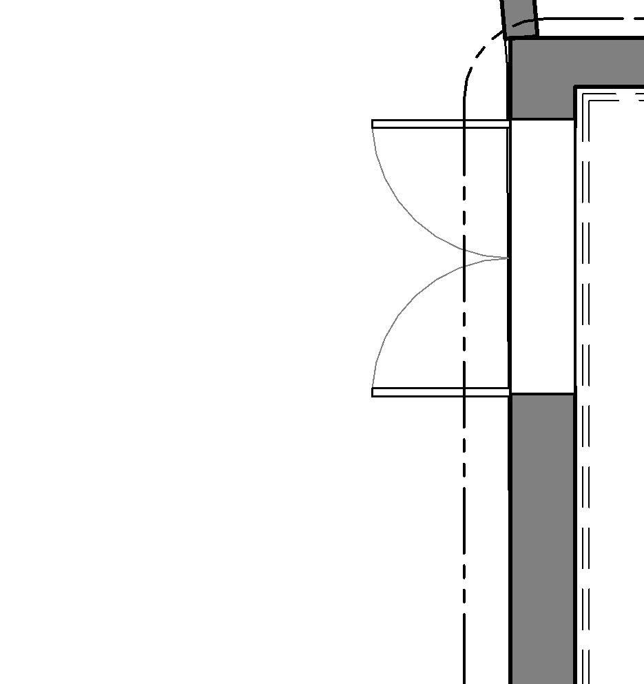
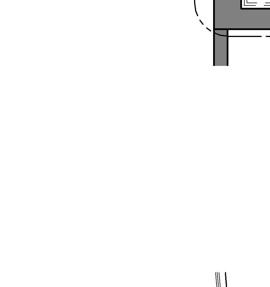
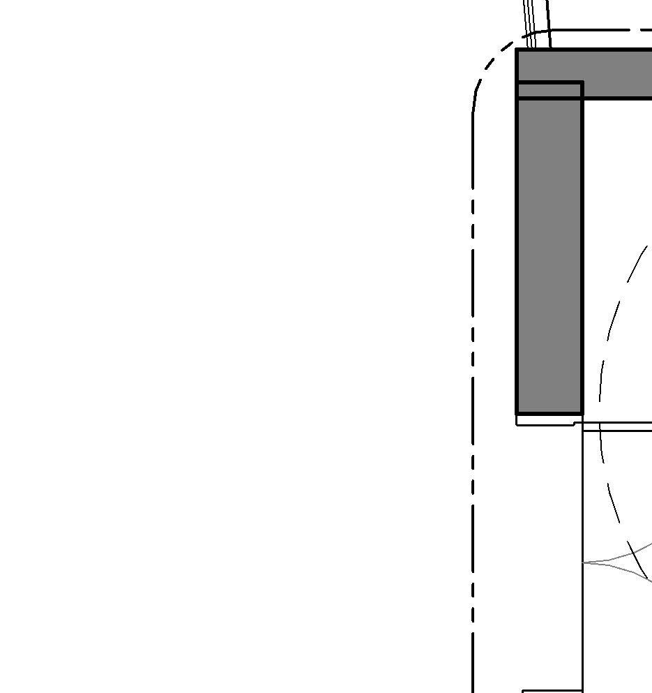
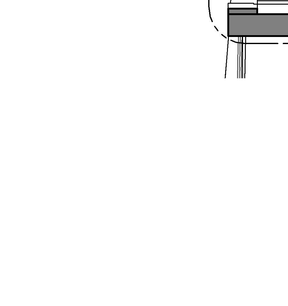
acccording to NFPA 101: Door leafs are permitted to encroach onto the landing at the top of a stair, but it must not reduce the landing to less than one-half of its required width, and in no case shall the landing be reduced to less than 22 inches (about 560 mm).
The total horizontal distance from one side of the stair assembly to the other — typically measured from wall to wall or outside edge to outside edge.
Includes structural elements like:
• Wall thicknesses
• Handrails
• Guardrails
• Trim or finish materials
• May not represent usable walking space
Used for:
• Overall stair layout in plans
• Material estimating
• Space planning
Clear Width
The unobstructed usable space between finished surfaces or between handrails — the actual width available for people to walk through.
Excludes:
• Handrail projections (usually 89 mm max on each side)
• Wall finishes (drywall, trim)
Directly related to code minimums and accessibility
Used for:
• Building code compliance (IRC, IBC, ADA)
• Means of egress calculations
• Accessibility evaluations
Scenario Use "Width" Use "Clear Width"
Framing/layout plans X
Code compliance & egress
Accessibility (e.g., wheelchair pass)
Estimating materials X
Headroom is the vertical distance measured from the leading edge (nosing) of a stair tread vertically up to the underside of any overhead obstruction, such as a ceiling, beam, soffit, or floor above.
Code Minimum Headroom Notes
IBC (2021) 2,030 mm (80 inches) Applies to most occupancies except where otherwise noted
IRC (2021) 1,980 mm (78 inches) For residential stairs (R311.7.2)
NFPA 101 (2021) 2,030 mm (80 inches)
Same as IBC for means of egress
ADA 2,030 mm (80 inches) Along accessible egress routes
• Construction tolerance for headroom is typically ±10 mm
• No localized projections (e.g., ducts, lighting fixtures) are allowed below the minimum clear height within the stair's walking line
• Tolerance must not cause violation of code minimums at any point
• In existing buildings, some codes allow less than standard headroom in renovations if no structural changes are possible (e.g., down to 1,880 mm in limited cases under IRC)
• In spiral stairs, reduced headroom may be allowed but only if explicitly approved by code official
• Beams or ductwork intruding into stair headroom
• Lighting fixtures mounted too low
• Skewed measurements that don't follow the nosing line (must be plumb vertical from tread nosing)
Planning Aspect Recommended Value / Guideline
Minimum vertical clearance (design) ≥ 2,100 mm to allow buffer for construction tolerance
Typical floor-to-floor height (residential)
2,700–3,000 mm
Distance from first tread to obstruction Maintain consistent clearance over entire stair flight
Consider sloped ceilings (e.g., attics)
Use headroom envelope (e.g., 2,030 mm minimum clearance line)
Headroom:
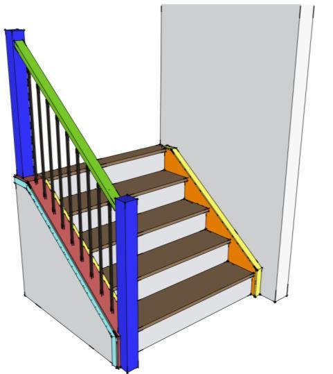
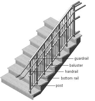
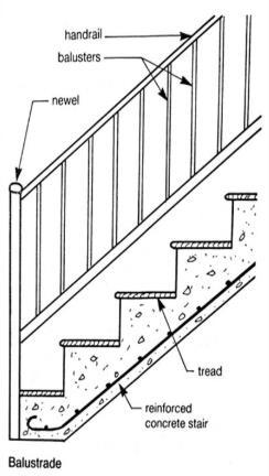
Post: vertical structural element at the start, end, or corner of a stair railing system that supports and anchors the handrail and balustrade
Handrail: A support rail that runs along one or both sides of the staircase to provide stability and prevent falls.
Shoe: small base or bracket that secures a baluster or railing post to the tread, landing, or stair stringer, providing stability and a clean, finished look.
Baluster (or Spindle): The vertical posts or supports that hold up the handrail.
Handrail
Baluster or spindle
Handrail height
865–965 mm (measured vertically from stair nosing) ADA/IBC require consistent height throughout the flight; ±10 mm typically allowed
Handrail diameter 32–51 mm (ADA/IBC)
Handrail clearance from wall ≥ 38 mm
Baluster (spindle) spacing
Post height
Shoe
Top rail (guardrail)
Structural load resistance
≤ 100 mm between balusters
Must allow full grip; circular preferred
To allow fingers to wrap around freely
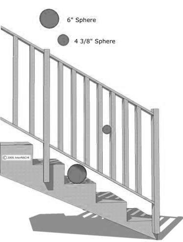
Sphere test: a 100 mm sphere must not pass through
Same as handrail or taller (≥ 965 mm) May vary for decorative or structural needs
Varies (commonly 25–50 mm footprint for residential applications)
≥ 1,065 mm above floor/landing (for guards, not just handrails)
Handrails must resist 890 N concentrated load (IBC)
* REFER TO CHAPTER 8 for more detailed information on Railings, posts, handrails, shoes, balusters and guardrails, and its dimensions and applicable regulations
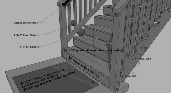
150 mm (6”) max. sphere Sphere rejection test → see chapter 8
100 mm (4-3/8”) max. sphere
Must fully cover baluster base; anchoring must be secure - a 150 mm sphere must not pass through
Required when fall height is ≥ 760 mm
Guardrails must resist 900 N/m uniform load
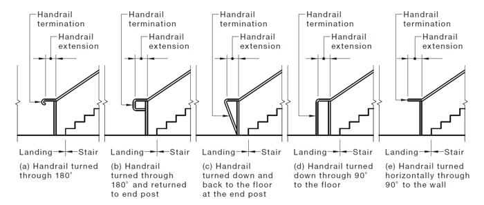
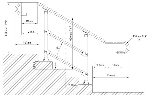
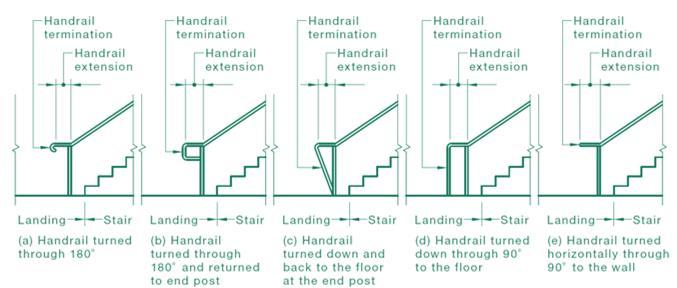
Handrail extension: The portion of a handrail that continues beyond the top or bottom of the stair flight. It provides additional support and safety as users begin to ascend or complete their descent on the stairs.
Handrail extension requirements (IBC)
Location Extension Type Length Required
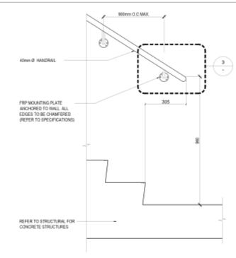
Top of stairs Horizontal extension ≥ 12 inches (305 mm)
Bottom of stairs Sloped extension (same angle as stair) Length of one tread (~11 in)
General Notes:
Extensions must be in the same direction as the stair run or landing. They must not obstruct the clear width of the stairs.
Exceptions apply in certain cases like:
• Where handrails are continuously connected (e.g., in a circular stair)
• In residential (Group R-3) or individual dwelling units in Group R-2 (e.g., apartments), extensions may not be required
Guardrail: A guardrail on stairs is a protective barrier installed along the open sides of a stairway to prevent falls to lower levels. It is required when the vertical drop exceeds 30 inches (762 mm) and must be at least 42 inches (1067 mm) high, measured vertically from the leading edge of the stair tread.
* REFER TO CHAPTER 8 for more detailed information on Railings, posts, handrails, shoes, balusters and guardrails, and its dimensions and applicable regulations
Pitch (or slope) is the angle of inclination of a stair flight, usually measured as the angle between the horizontal and the line connecting the nosings of successive treads. It can also be expressed as a rise-to-run ratio, grade (%), or directly in degrees (°).
Code / Standard Acceptable Pitch (Angle) Rise/Run Guidelines Notes
Max riser: 180 mm
IBC (2021) 20°–37°
IRC (2021) < 37.5° (recommended)
NFPA 101 (2021) 30°–35° (typical range)
OSHA (Workplace) 30°–50°
Min tread: 280 mm Applies to most nonresidential buildings
Max riser: 197 mm
Min tread: 254 mm For residential stairs
Max riser: 180 mm
Min tread: 280 mm Means of egress stairs
Rise/run ratio: 7:11 typical For industrial settings
Ideal Pitch Range (Comfort + Safety)
Most comfortable pitch: 30°–34° Corresponds to rise/run ratios of 170–180 mm rise and 280–300 mm tread Ensures safe walking rhythm and reduced trip hazard
Tolerances
• Riser height’s typical tolerance:
• ±3 mm within a flight
• Tread depth’s typical tolerance:
• ±5 mm but consistent
• Overall slope: not explicitly specified, but derived from uniform rise/run values
Uniformity is critical: The slope must remain consistent across a flight. Irregularities cause trips and code violations.
tip

Example:
Riser = 175 mm; Tread = 280 mm; Pitch = 32.5° (comfortable and code-compliant)
Design Element
Planning Value
Typical rise/run (public stairs) 170 mm rise / 280 mm tread
Maximum pitch (public use) ~37°
Minimum pitch (to avoid long run) ~20° (flatter = ramps)
Stair run depth (incl. nosing) Typically 280–300 mm including 25 mm nosing
This chapter outlines the key requirements and considerations for the design of evacuation stairs. For correct egress design, an FLS specialist must always be consulted.
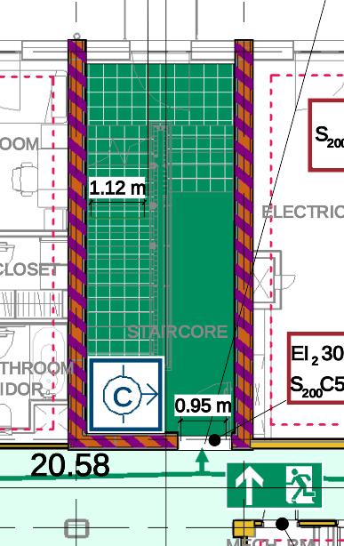
5.1 Fire Resistance and Enclosure.
Egress staircores must be enclosed within fire-rated constructions with specific requirements depending on the type of building
- Fire Resistance Rating 1/2 hour
- Fire Resistance Rating 1 hour
- Fire Resistance Rating 1 1/2 hour
Enclosures protect evacuees from heat, flames, and smoke. Doors must be self-closing and smoke-sealed.
5.2 Lighting and Signage
Emergency lighting is required in stairwells for safe evacuation during power outages. Illuminated exit signs must be placed at all entry points.
5.3 Accessibility Considerations
People with limited mobility may not be able to use stairs during an emergency. Areas of Refuge (AOR) or Areas of Assisted Rescue must be provided within staircores:
- Size: Enough for at least 1 wheelchair space (≥ 760 mm x 1220 mm) per 200 occupants
- Equipped with two-way communication systems to alert emergency personnel
- Fire-rated, ventilated, and smoke-protected
- Located on each accessible floor, usually adjacent to stair landings.
5.4 Slip Resistance and Visual Contrast
Stair treads must be non-slip, even when wet
Visual contrast strips on nosings improve safety for people with low vision. Materials and finishes should comply with ADA/ABA accessibility guidelines.
5.5 Arrangement of Means of Egress
Exits shall be located, and exit access shall be arranged, so that exits are readily accessible at all times.
↑ Evacuation route
Fire-resistance rating requirements for stair enclosures (depending on the regulation, between 30 min and 2h):
• 30 minutes rating
• 1 hour rating
• 1 ½ hour rating
Enclosures must be constructed with non-combustible materials and be continuous from the lowest point of egress to the final exit discharge.
Doors to stair enclosures must comply with the following criteria:
Minimum clear width of 900mm for ABA compliance when ABA is applicable (i.e.: for refuge areas)
Overhead self-closing
Smoke seal which means that the door is Bottom sealed
Penetrations into the stair shaft (e.g., ducts or pipes) must be firestopped per IBC Chapter 7.
In certain cases, the frame and door leaf must be metal, depending on the type of building. For example, the 'UEPH Standard Design Guidance' requires this for this type of facility.
Standpipe and hose systems shall be provided in accordance with NFPA 14, but only in certain occupancy type of facilities.
* RELEVANT CODES for further information
IBC, NFPA 101 and UFC 3-600-1.
Always must consult an FLS specialist
↑ Staircore fire protected by
Emergency lighting:
Must provide a minimum of 1 foot-candle (≈ 10.8 lux) at walking surfaces during emergency operation (NFPA 101 §7.9).
Must function for at least 90 minutes in the event of power failure (IBC §1008.3.4).
Photoluminescent materials have been used effectively as internally illuminated exit and directional exit signs
Illuminated and readable from at least 30 meters (100 feet).
Placed above or adjacent to exit doors
Low-level lighting may be required in stairwells in certain occupancy types (e.g., aircraft hangars, detention facilities, per UFC or special NFPA provisions).
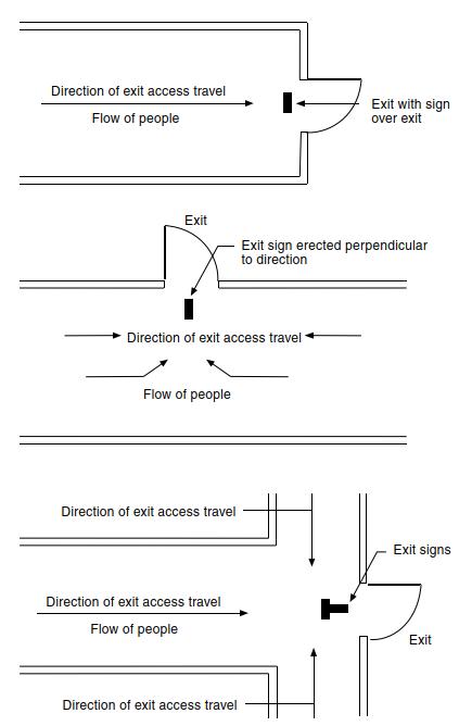
Directional exit signs should be installed where the horizontal egress path changes directions. The stairway marking sign, provided within the stair enclosure at each floor landing, indicate the vertical direction to exit discharge.
* RELEVANT CODES for further information
IBC, NFPA 101 and UFC 3-600-1.
Always must consult an FLS specialist
escaping a building taking the stairs ↑ Location of exit signs
While stairs aren't accessible to all users, accessible means of egress must be provided from every accessible space:
A means of egress is considered an accessible if it meets one of the following criteria:
1. A wheelchair-bound person is able to travel unassisted through the exit access, exit, and exit discharge to a public way (i.e., ramp-type travel and not stair-type travel if elevation differences are involved).
2. A wheelchair-bound person is able to travel unassisted through that portion of the exit access necessary to reach an area of refuge.
For an area of refuge to be considered an accessible area of refuge, it must be capable of being reached by a person in a wheelchair without traveling over stairs or other obstacles.
- Located within or adjacent to stairwells (IBC §1009.6).
- Must allow a wheelchair turning space (min. 30" x 48" / 760 mm x 1220 mm). Such wheelchair spaces shall maintain the width of a means of egress to not less than that required for the occupant load served and to not less than 36 in. (915 mm).
- Equipped with two-way communication connected to emergency response
- Must be identified by a sign Reading: AREA OF REFUGE
* RELEVANT CODES for further information
IBC, NFPA 101 and UFC 3-600-1.
Always must consult an FLS specialist
Tread surfaces
Must be Firm, stable, and slip-resistant, especially in wet conditions.
Visual contrast
Nosings should contrast visually with the rest of the tread to assist those with low vision.
Stair nosings
Shouldn’t project more than 1 ¼ inches (32 mm) Be beveled or rounded to avoid tripping hazards.
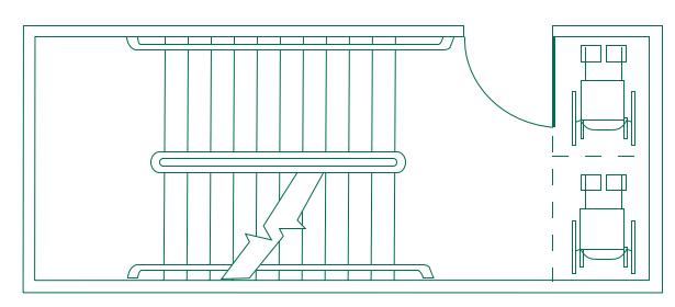
↑ Exit Stair Used as an Area of Refuge
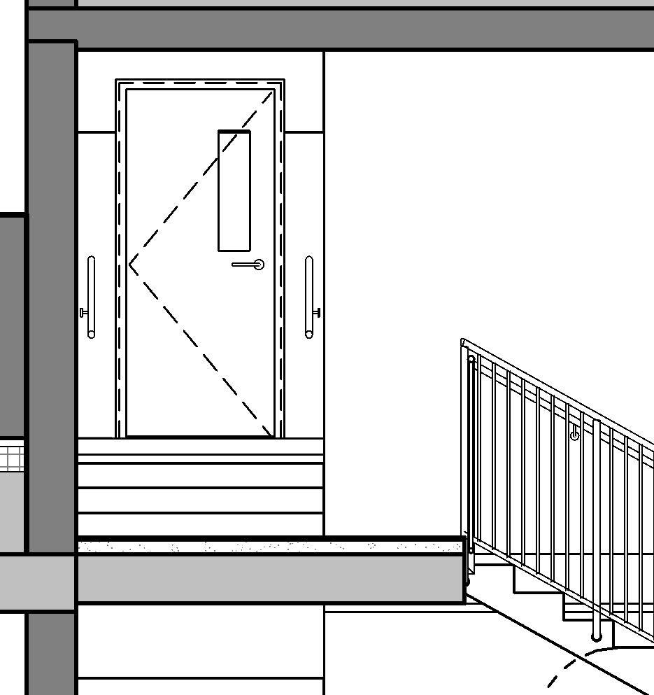
General considerations
escaping a building taking the stairs
- Exits shall be located, and exit access shall be arranged, so that exits are readily accessible at all times.
- Corridors shall provide exit access without passing through any intervening rooms other than corridors, lobbies, and other spaces permitted to be open to the corridor, unless otherwise provided in NFPA 101 (7.5.1.2.1 and 7.5.1.2.2).
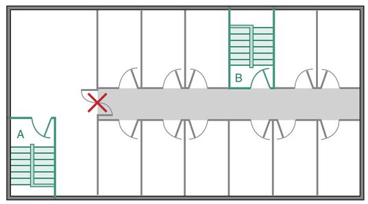
↑ Deficient corridor exit access
* RELEVANT CODES for further information
IBC, NFPA 101 and UFC 3-600-1.
Always must consult an FLS specialist
what are my options?
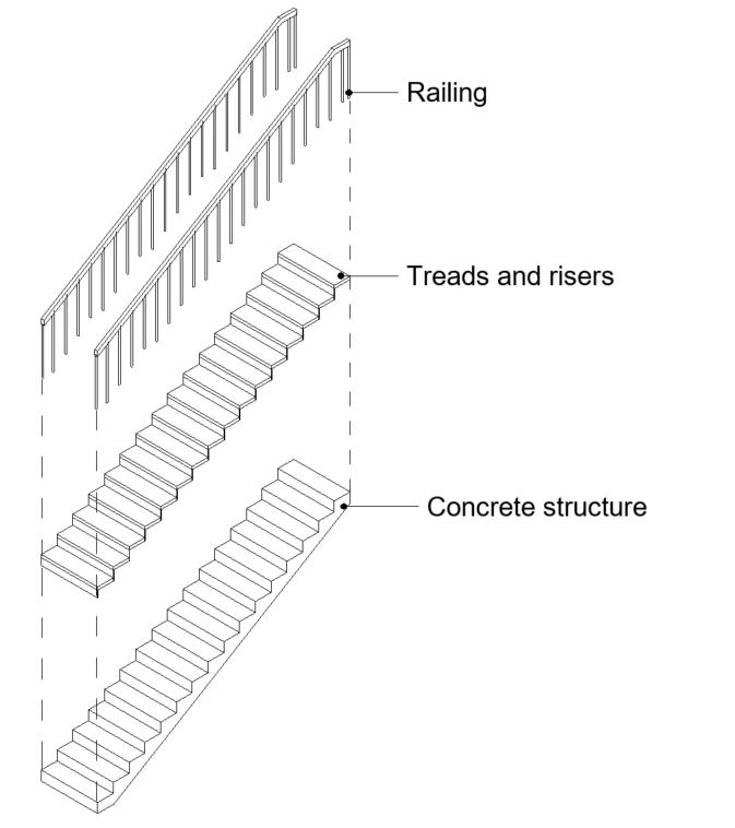
Stairs can be categorized based on their construction and installation process.
- Made up of prefabricated components such as treads or risers that are assembled on-site
- Typically made of Steel or Wood
- Widely used in industrial construction
- Constructed directly on-site by pouring concrete into custom-made formwork
- High structural integrity and fire resistance
- Integrated into the building structure
- Bespoke, risers do not have to be rounded
- Factory-cast in concrete and delivered to site as complete flights or modular units
- High Fire resistance
- Fast to install
- Thread and riser finish is installed on-site
- Risers have to have round dimensions, depending on the manufacturer
- Finish is usually prefabricated as well, and anti-slip strips are typically integrated
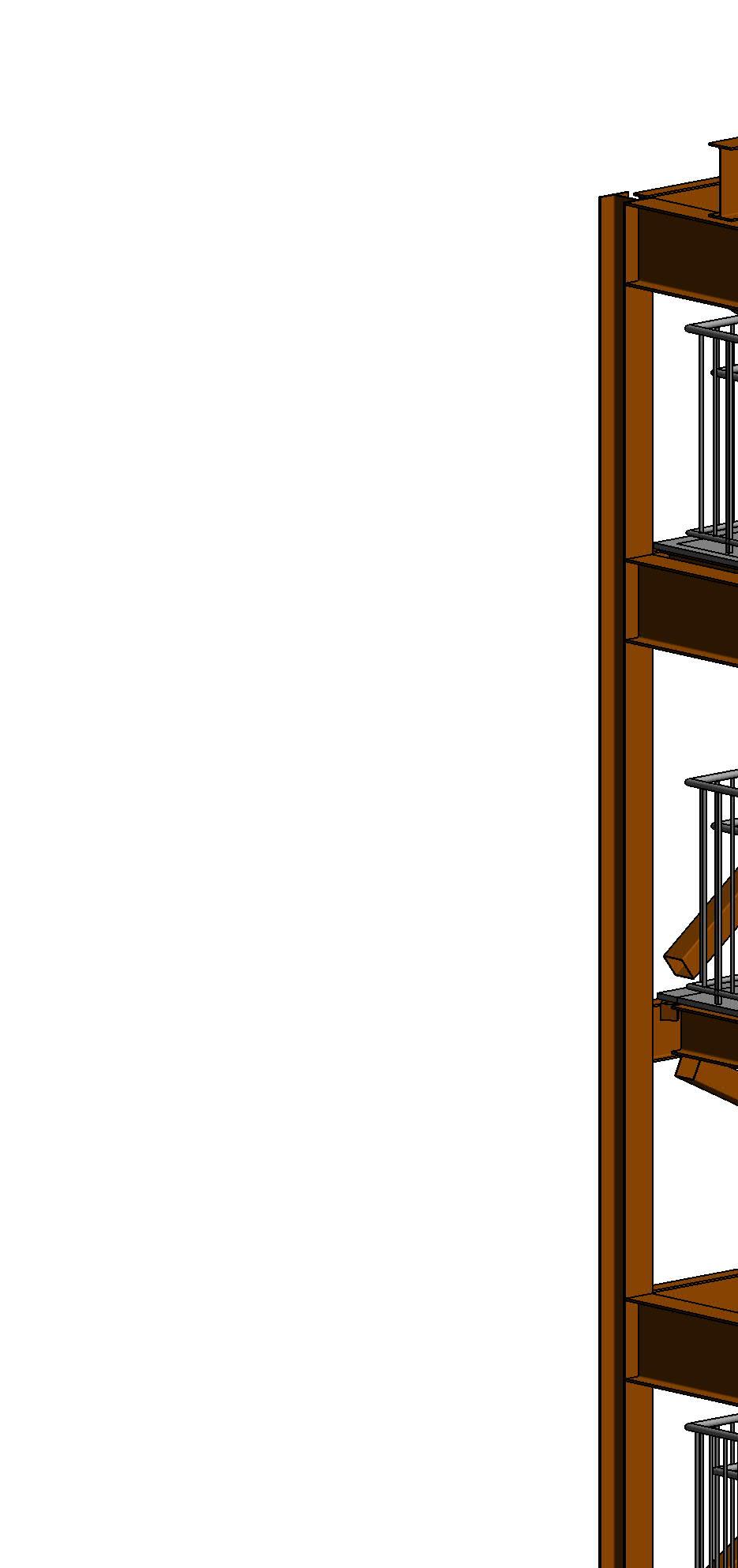
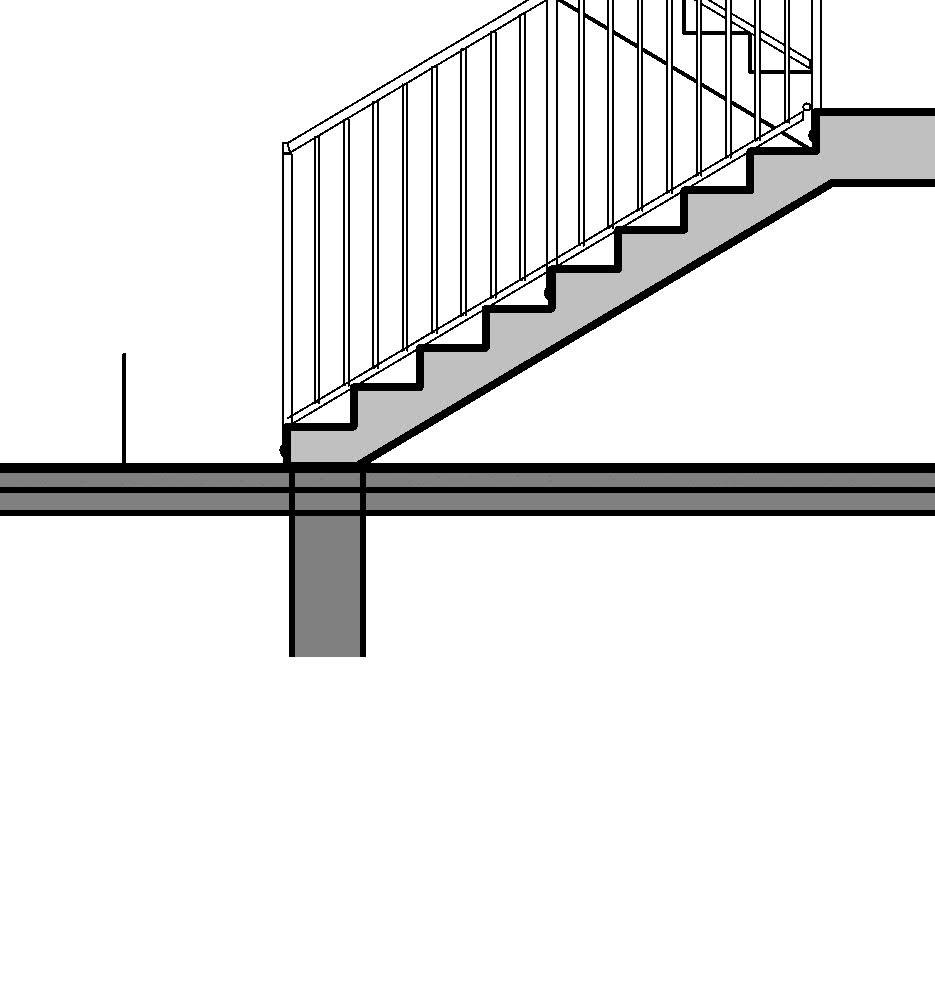
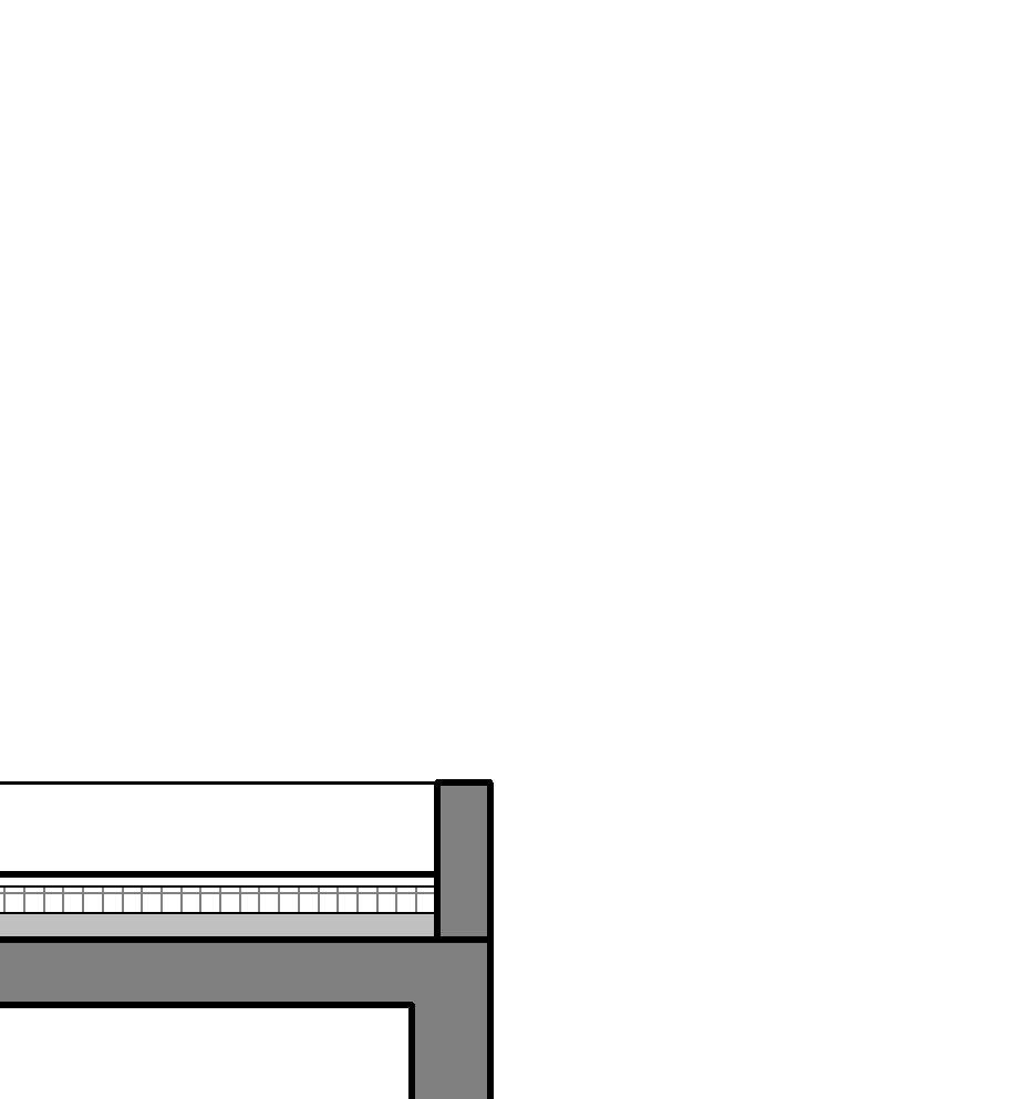
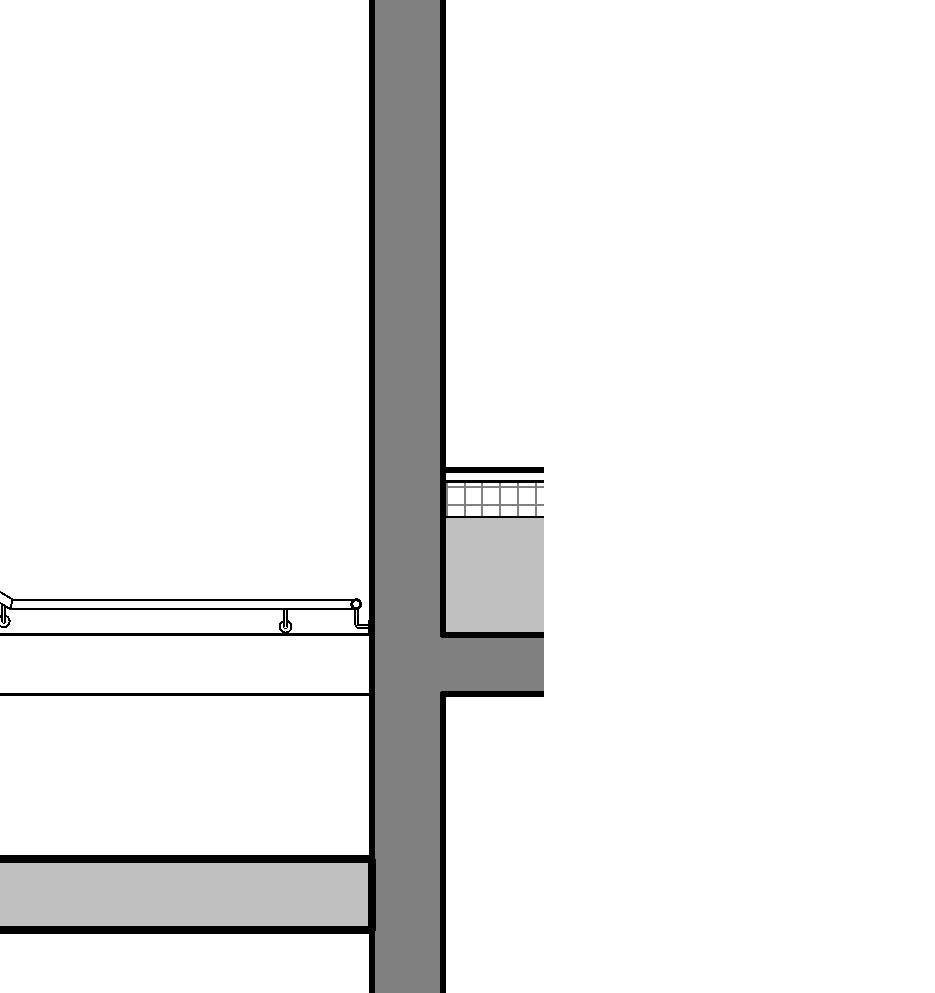
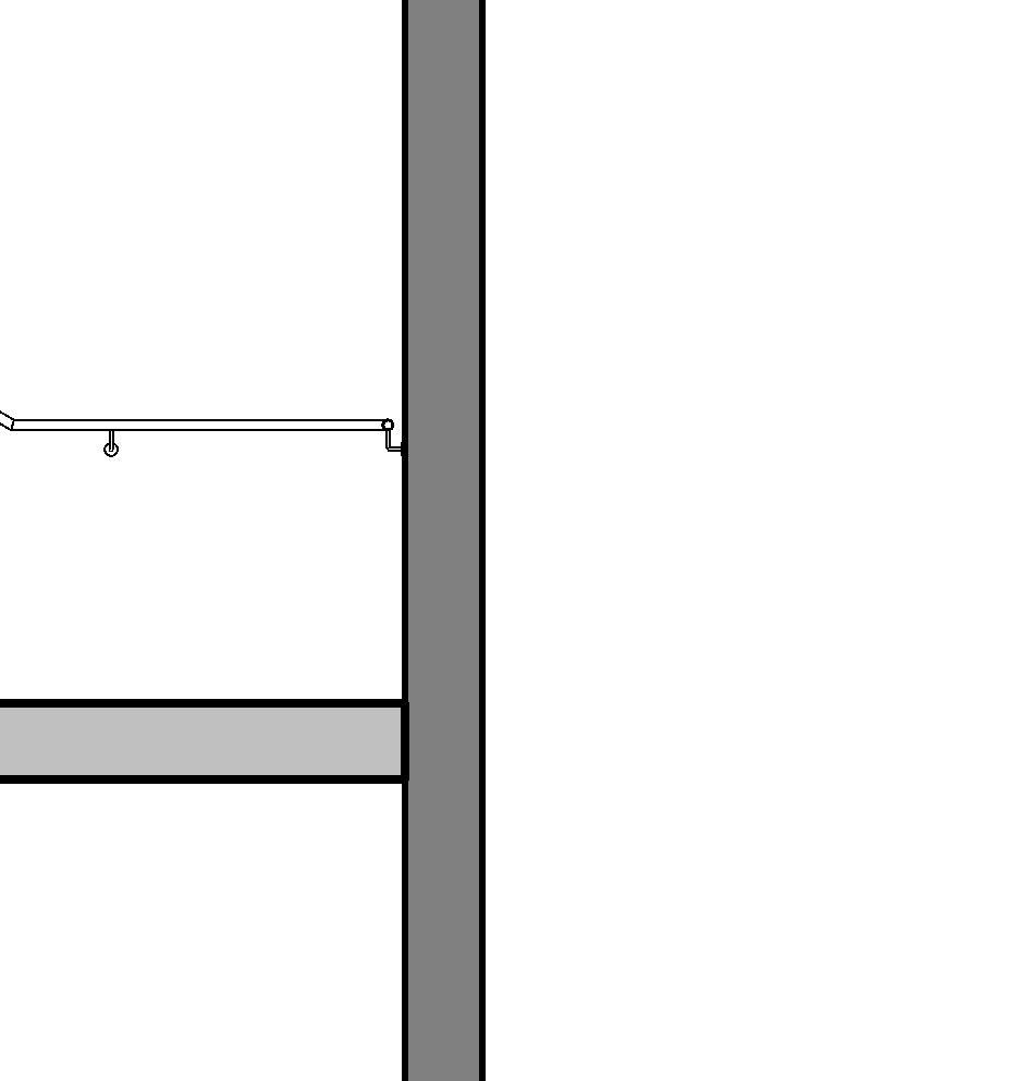
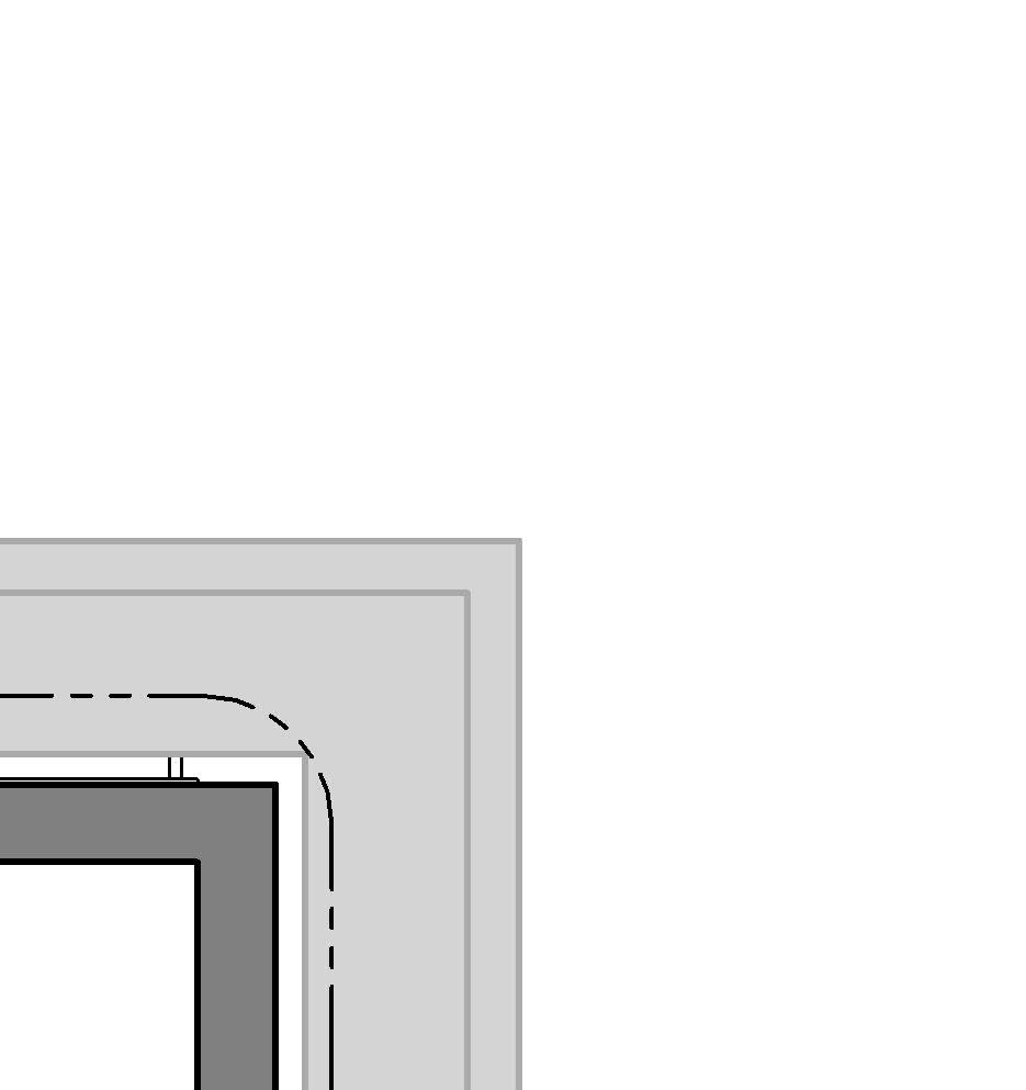
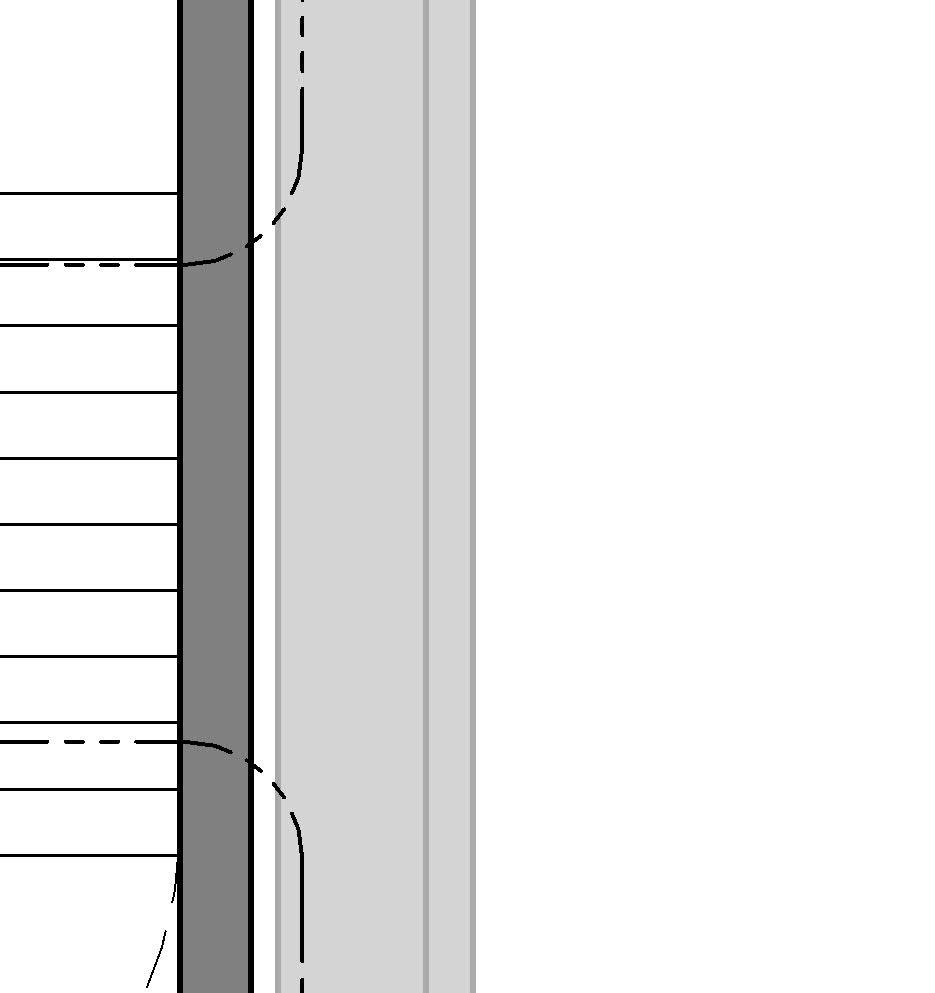
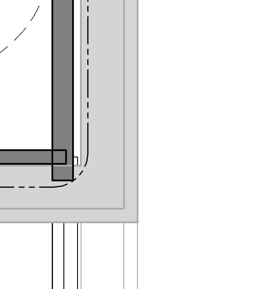
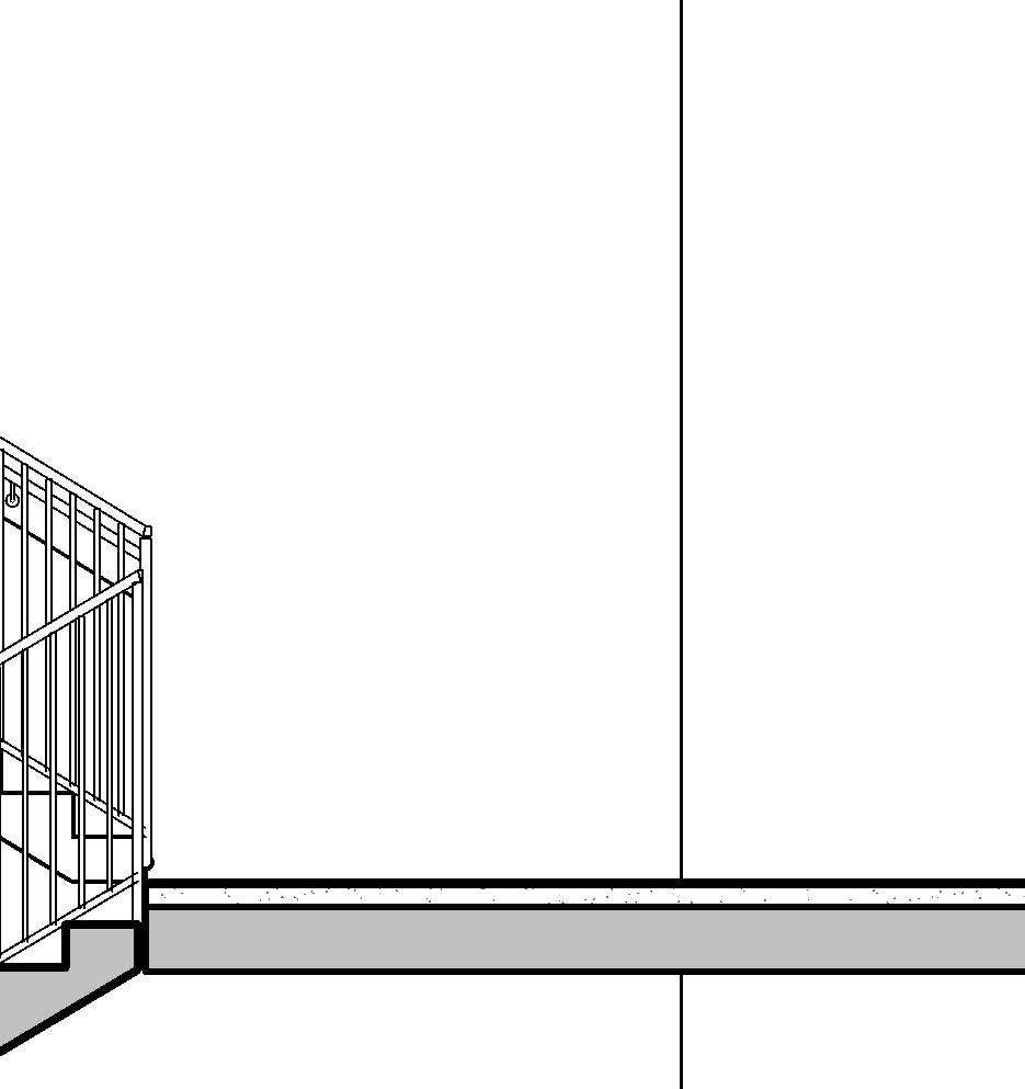
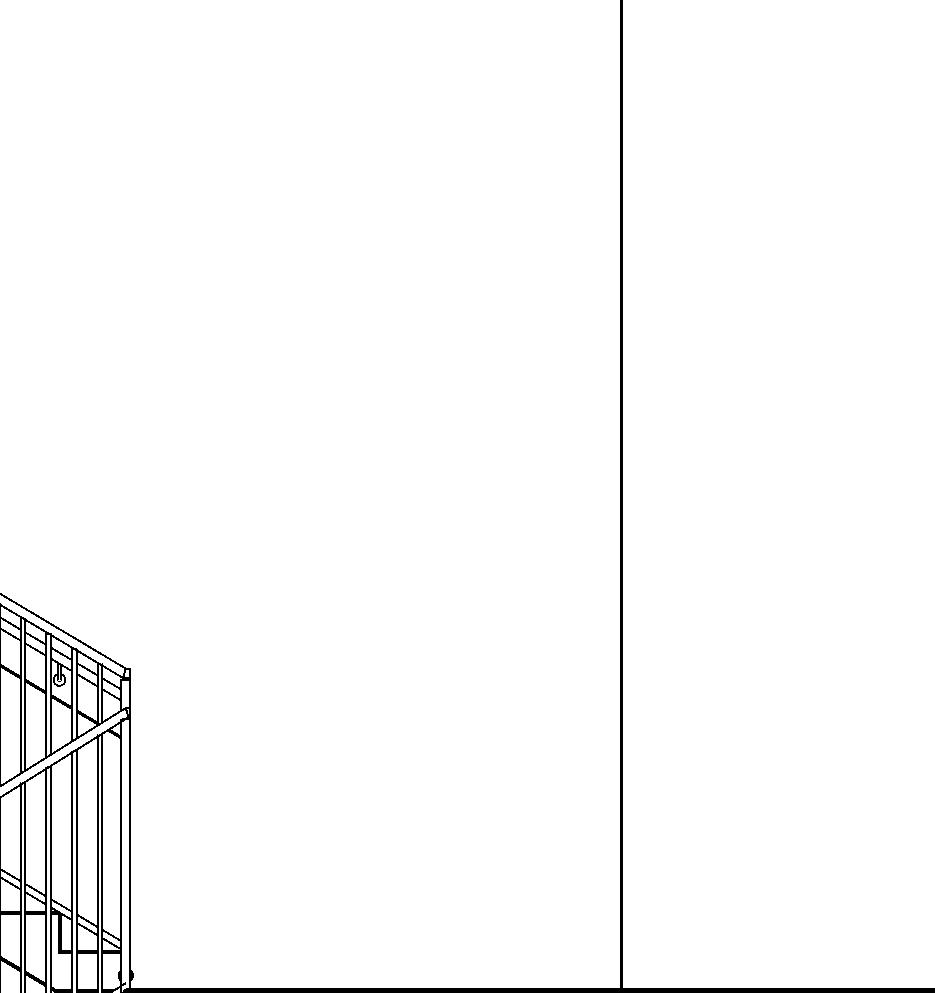
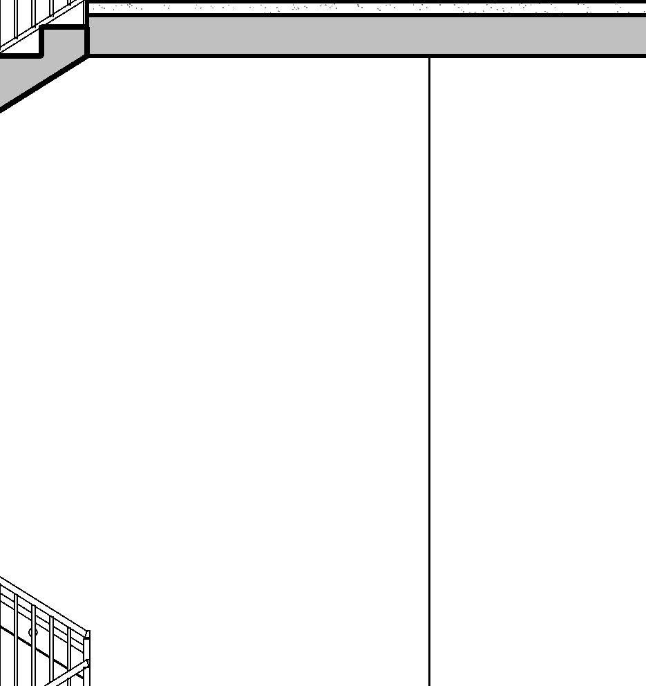
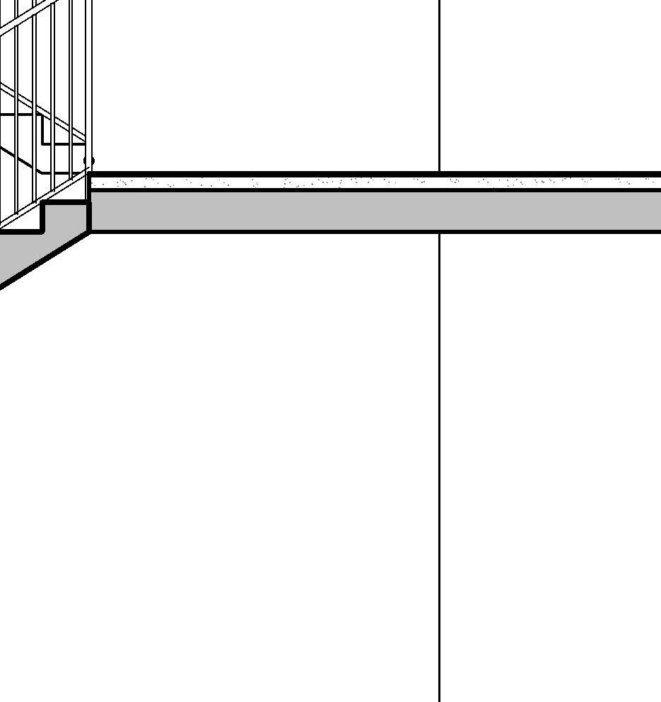
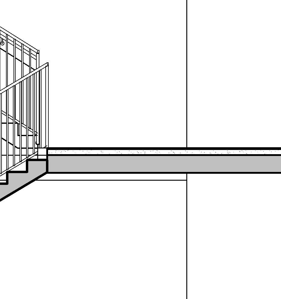
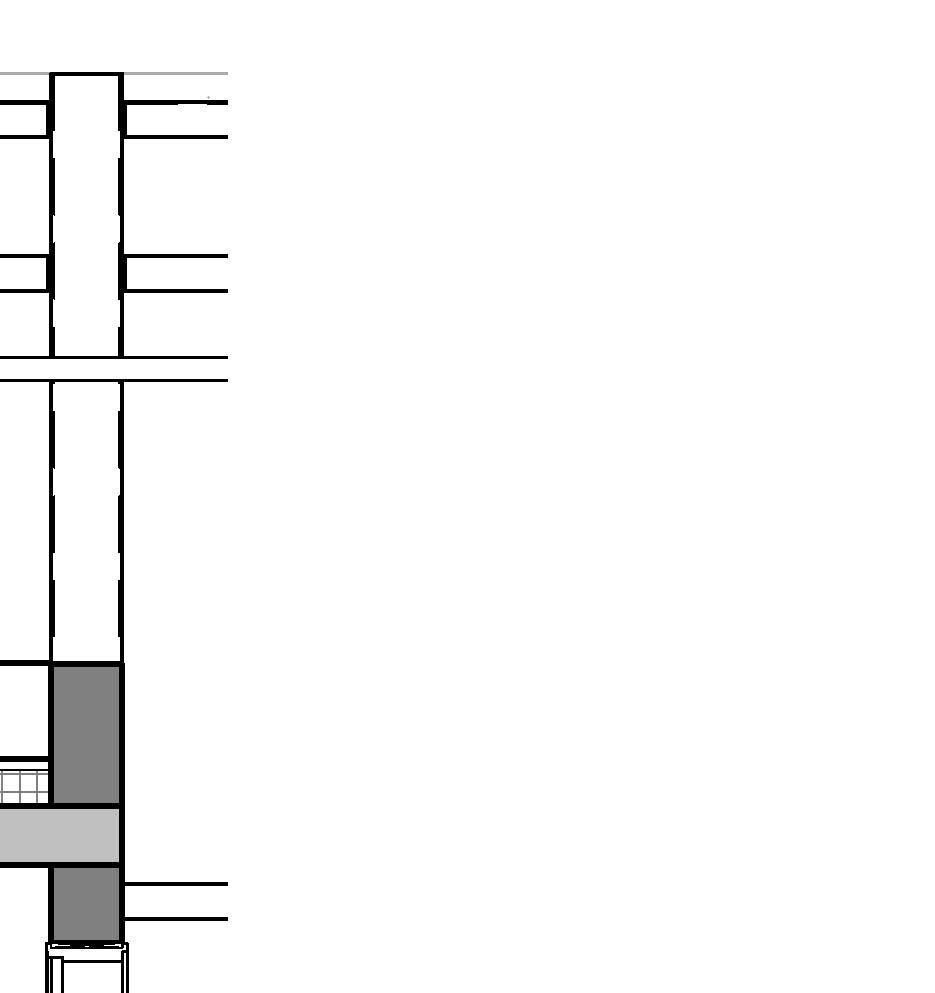
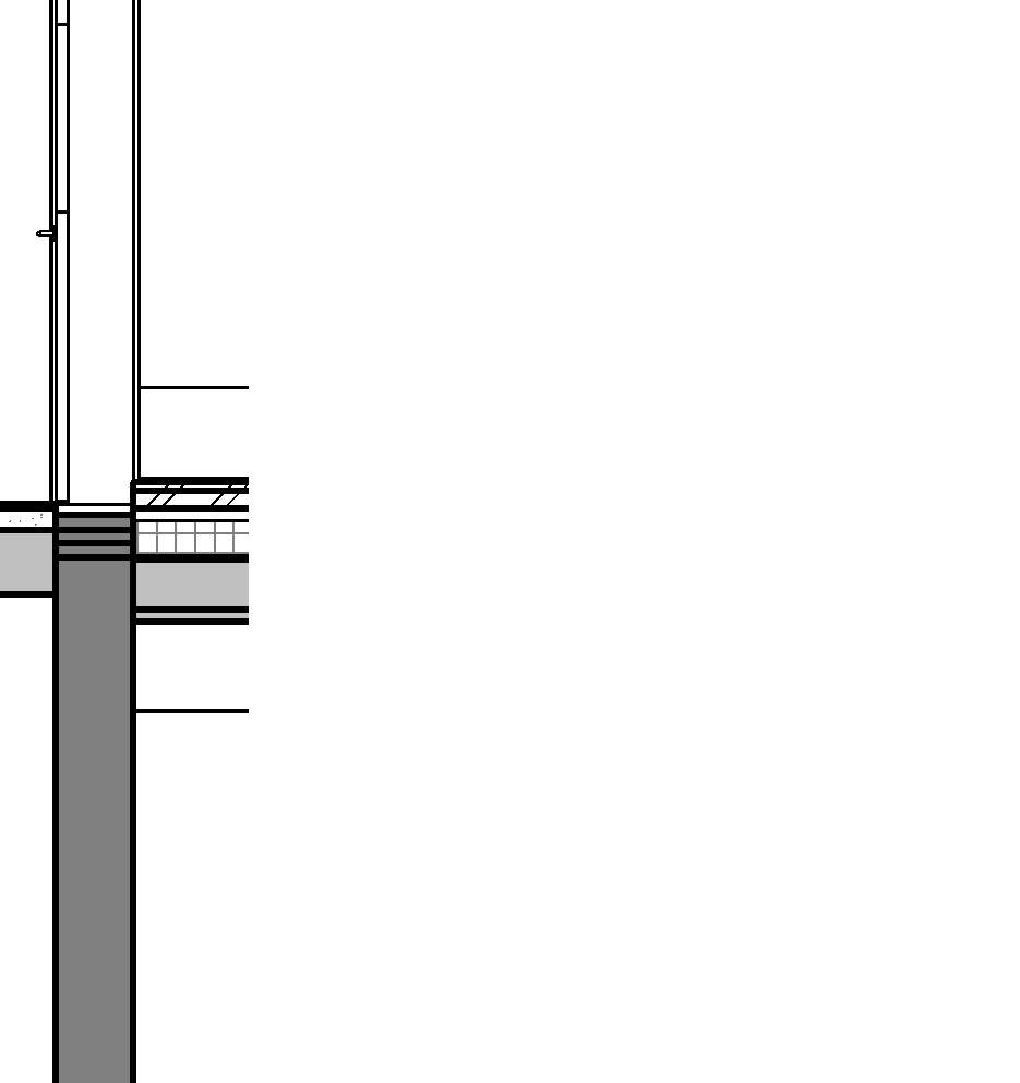
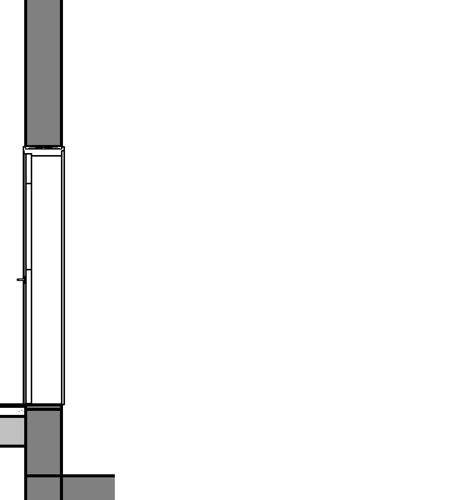
- Preassembled Steel stair unit fabricated off-site
- Commonly used in industrial buildings and secondary accesses of residential buildings, as well as exterior access and egress.
- When combined with grating, it minimizes slipping hazard, especially in winter due to ice.
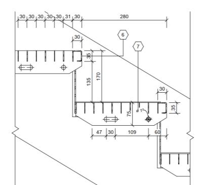
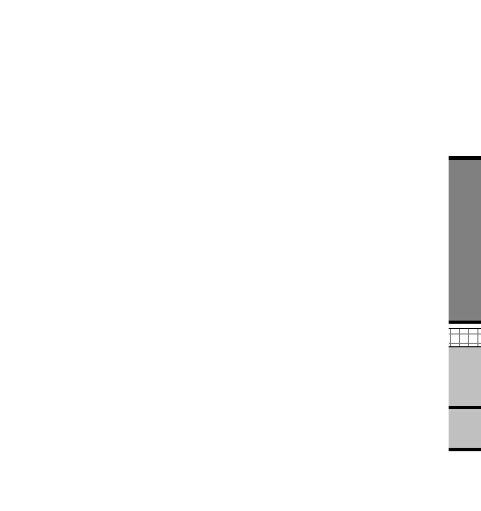
1 GRATING FLOORING
2 STEEL RAILING
3 MINERAL WOOL INSULATION
4 RENDER SYSTEM WITH GLASS FIBER MESH
5 REINFORCED CONCRETE WALL
6 CHECKER PLATE NOSING
7 STAIR TREAD-HOT-DIP-GALVANIZED STEEL
S235 GRATINGS WITHINCREASED SLIP RESISTANCE AND SIDE FRAMING
9 STRINGER, 400MM WIDE
11 METAL GRATING PLATFORM
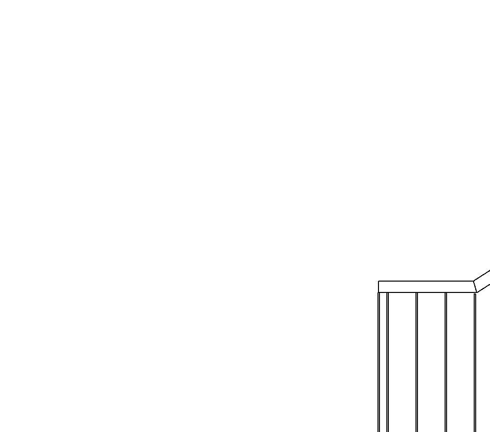
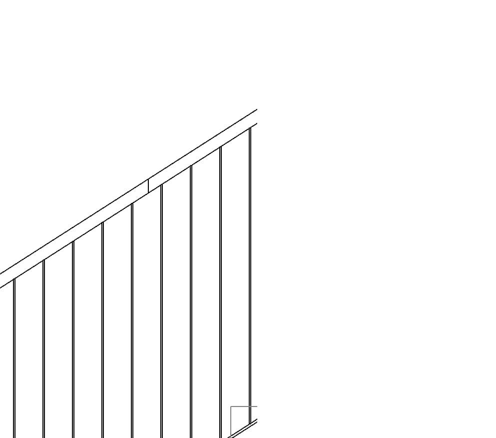
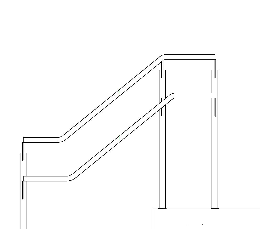
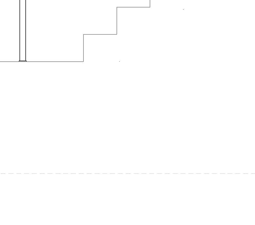
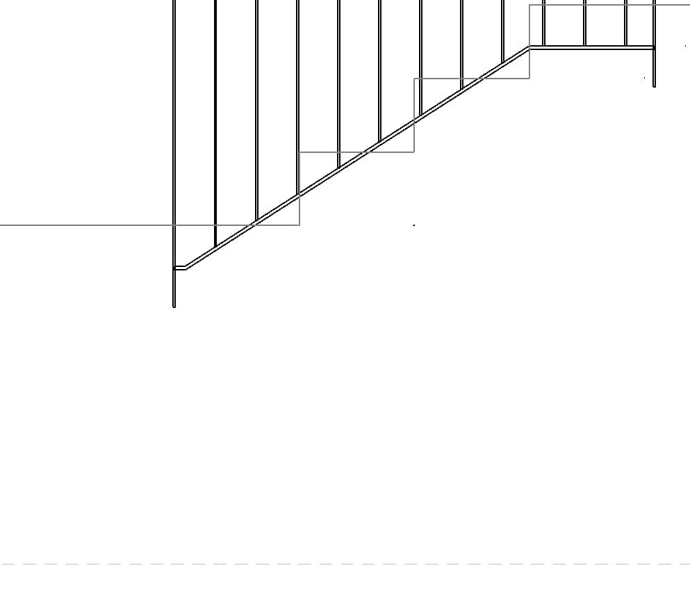
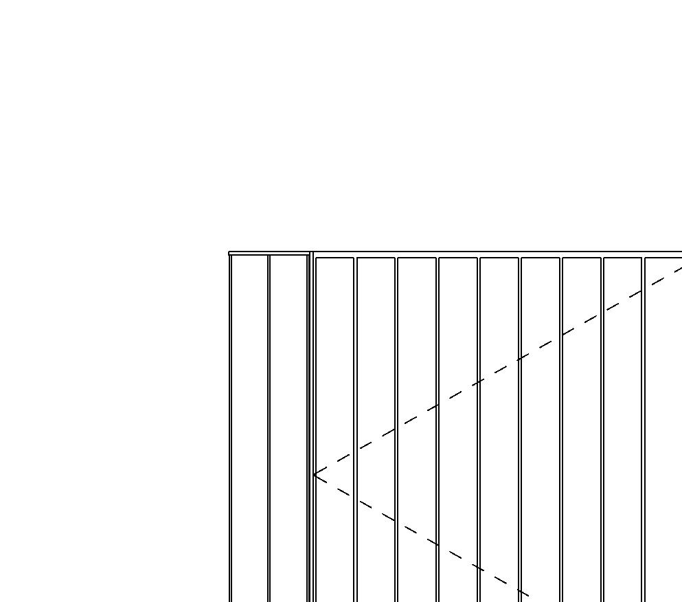
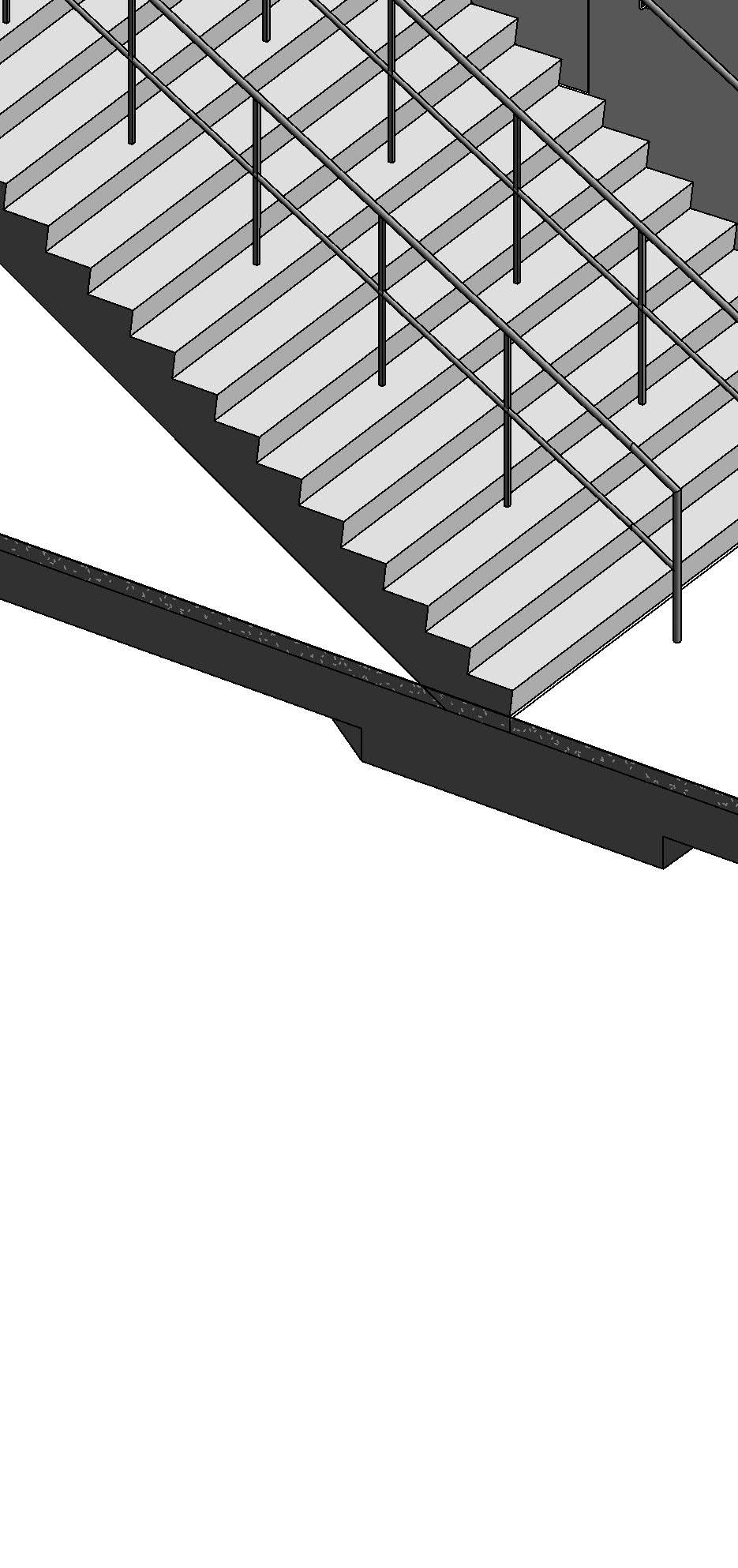
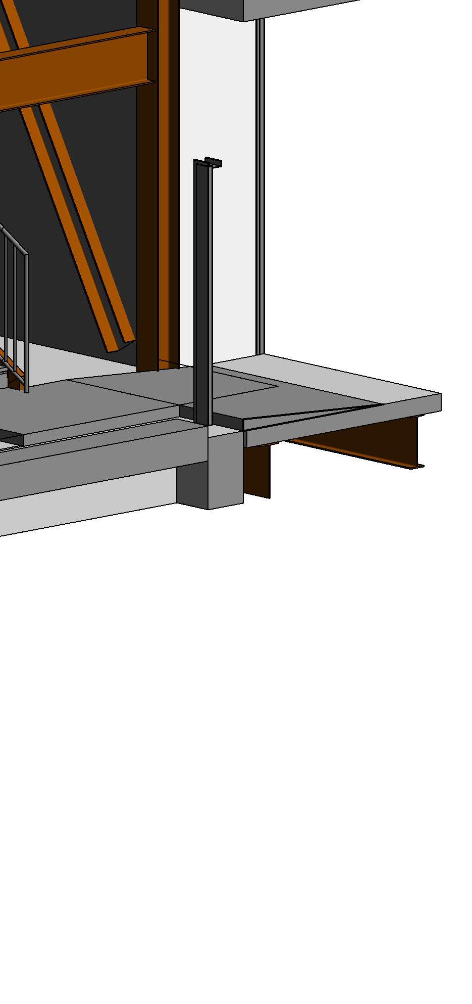
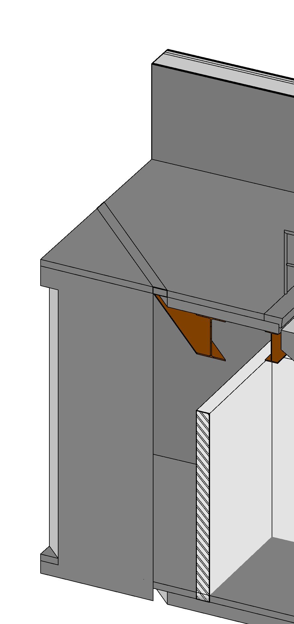
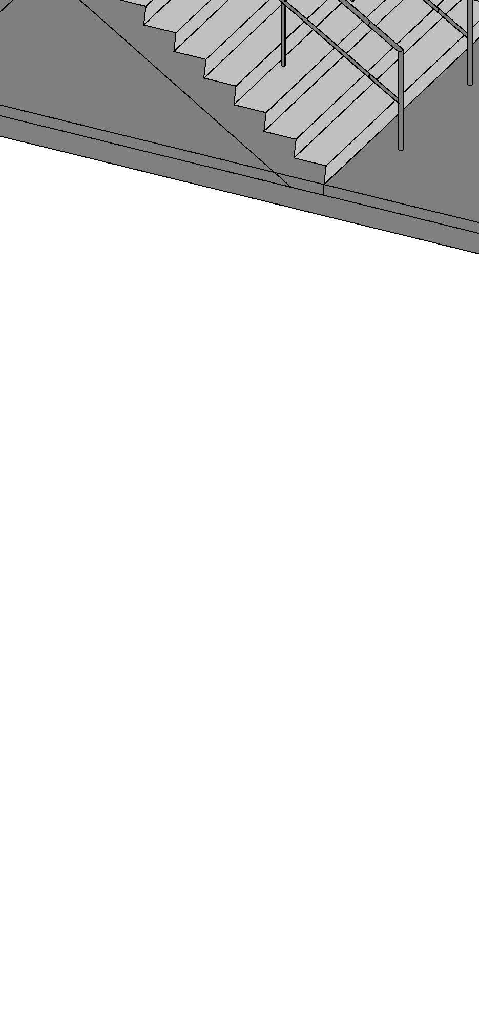
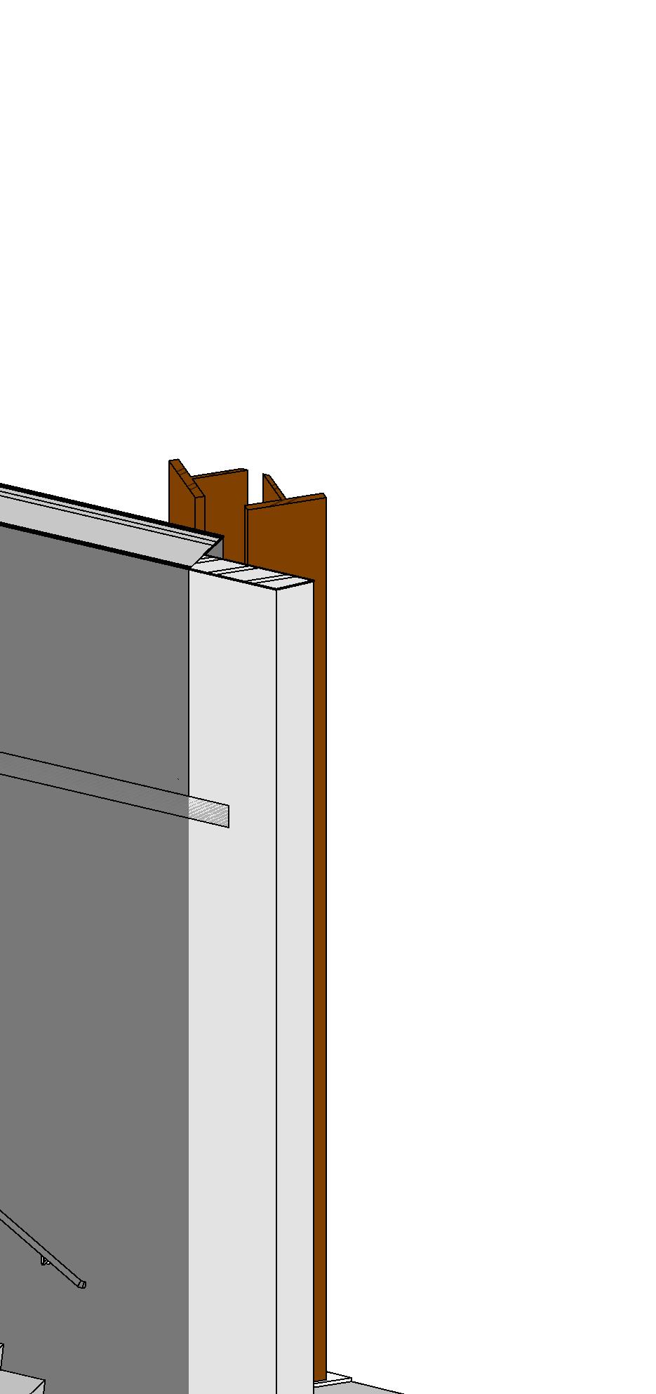
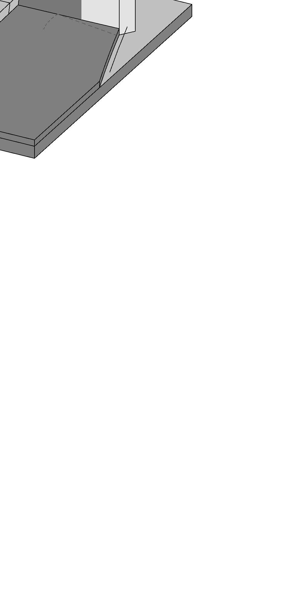
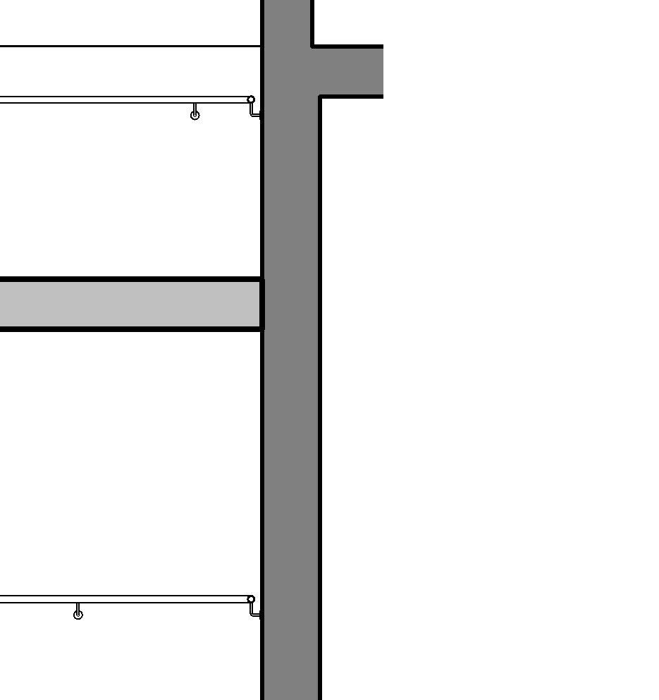
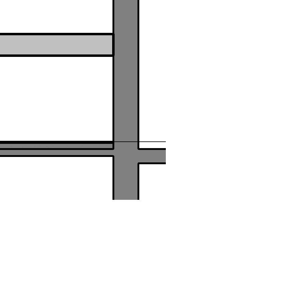
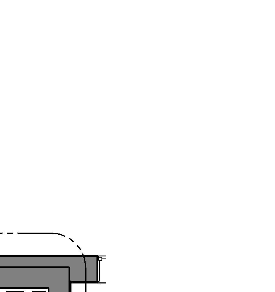
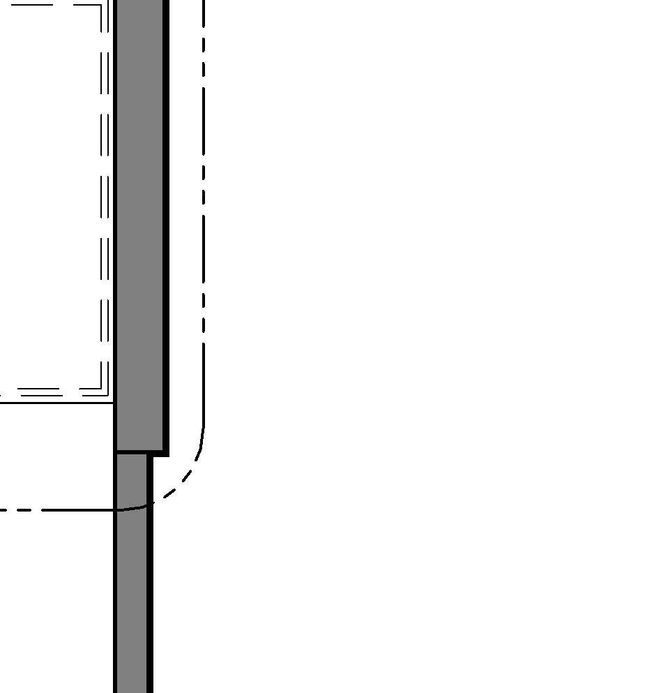
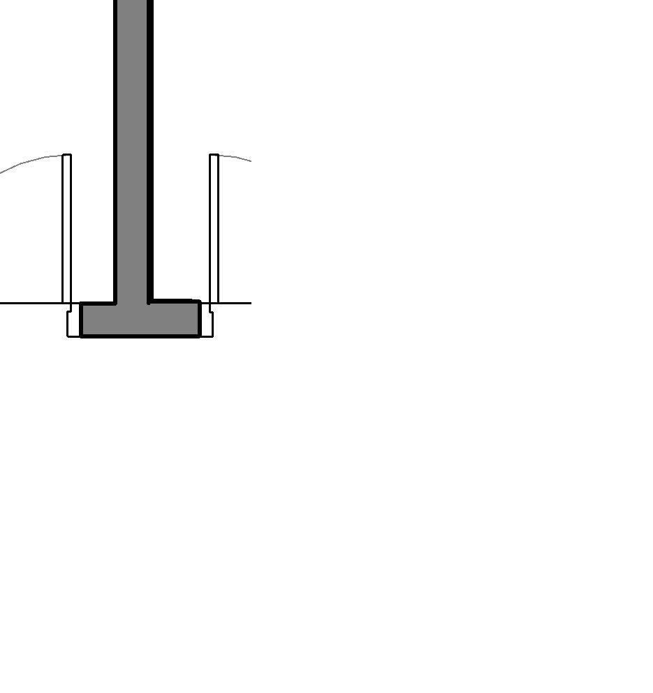
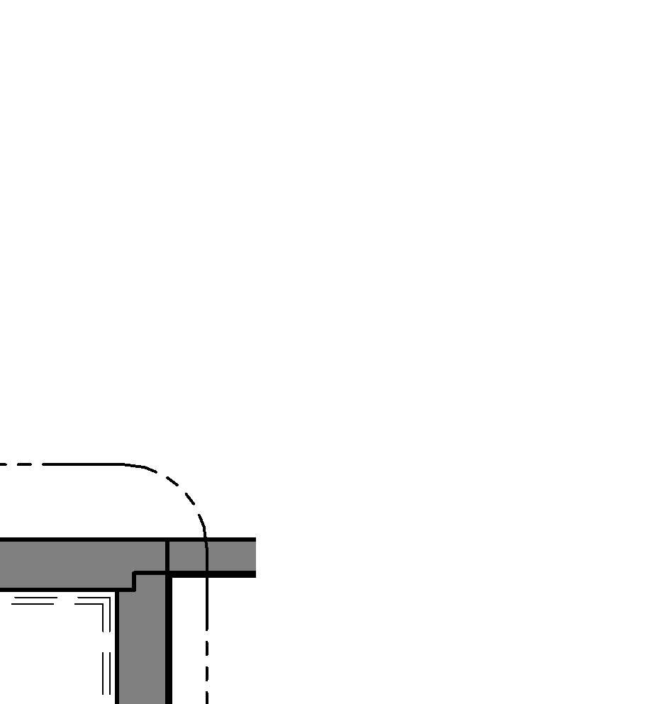
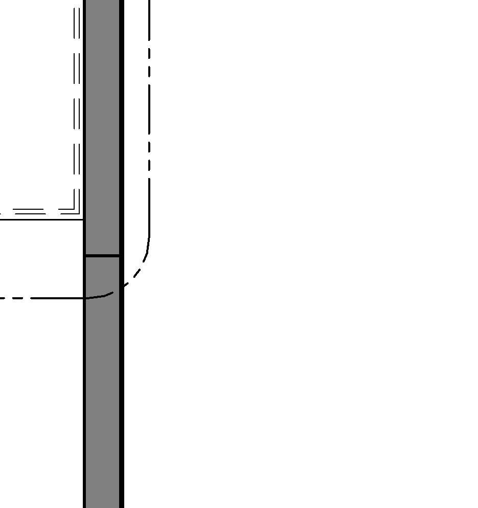
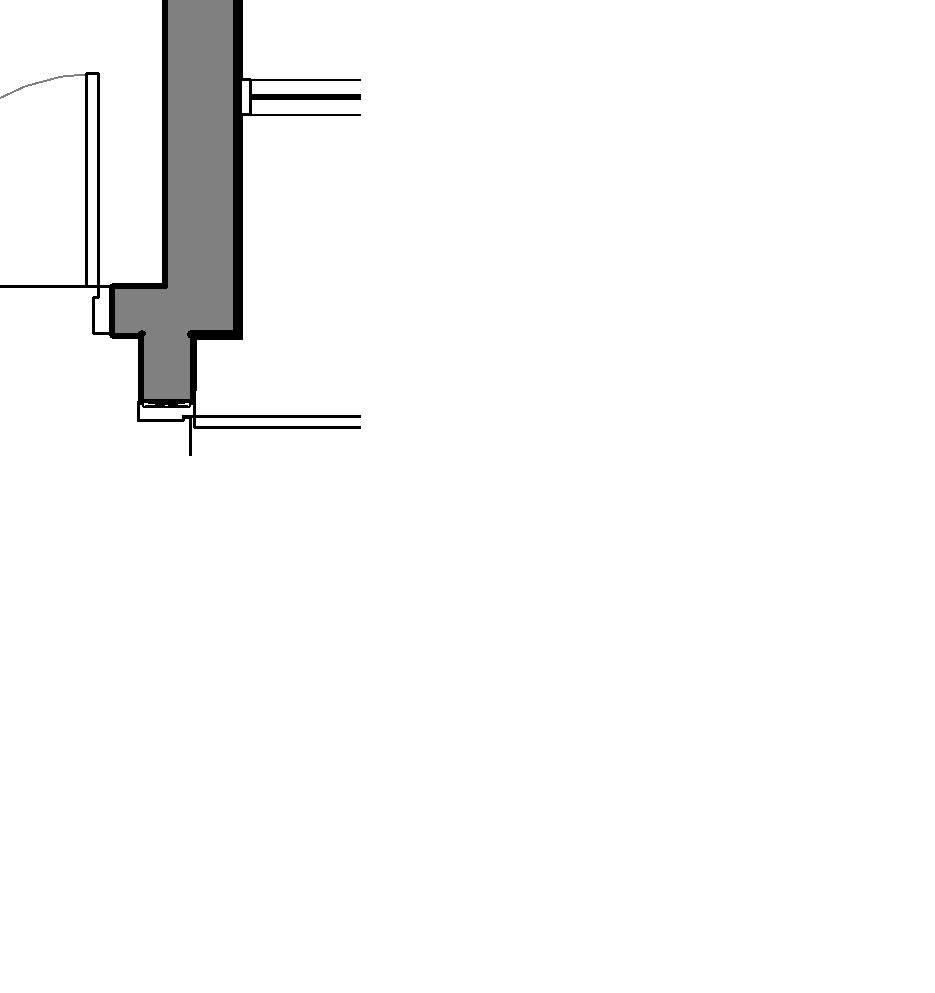
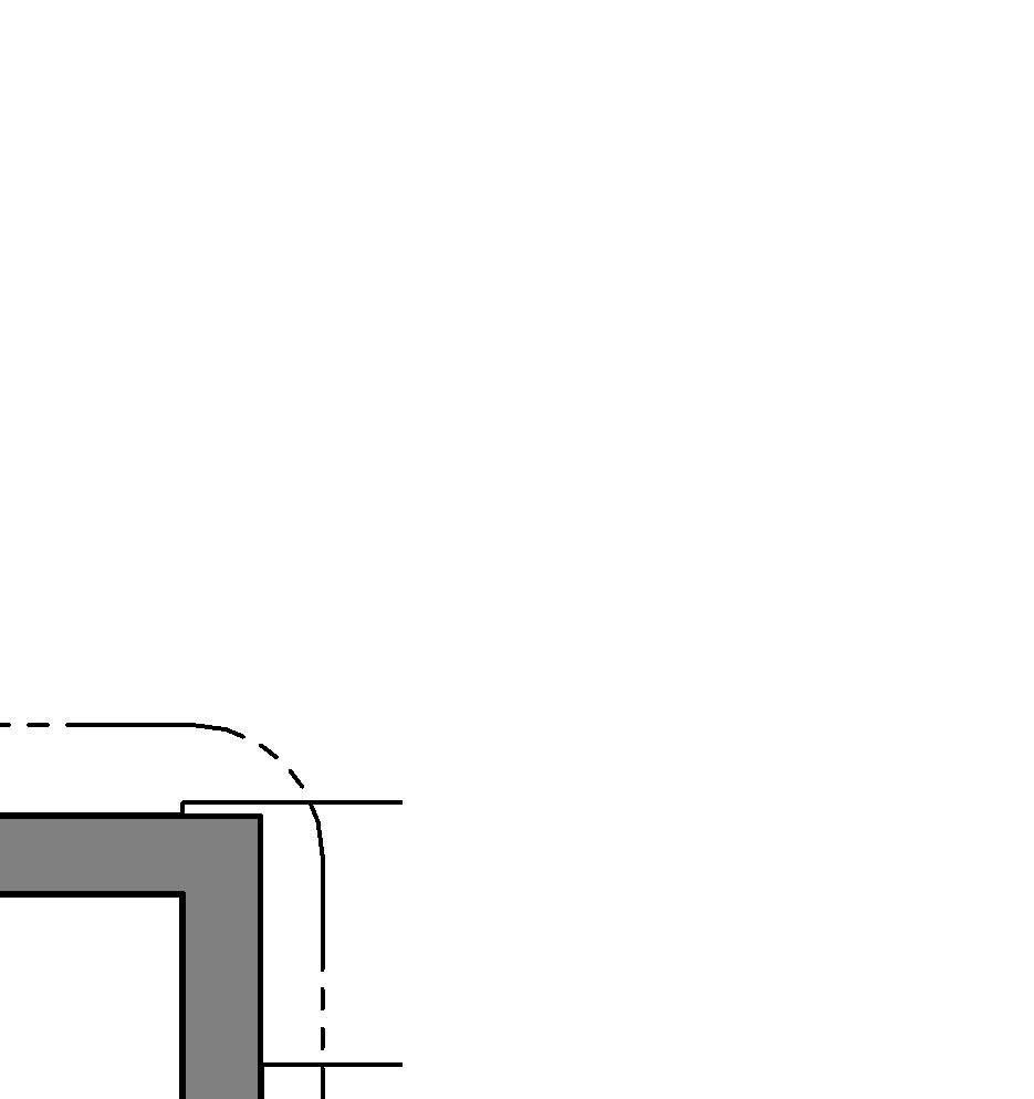
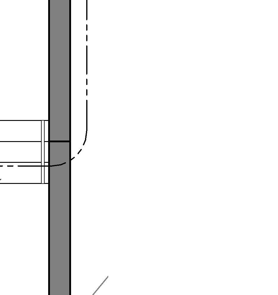
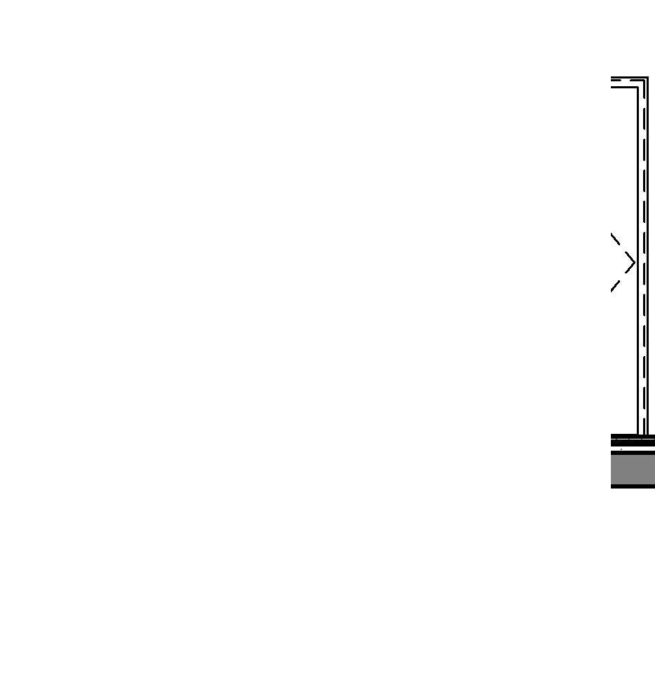
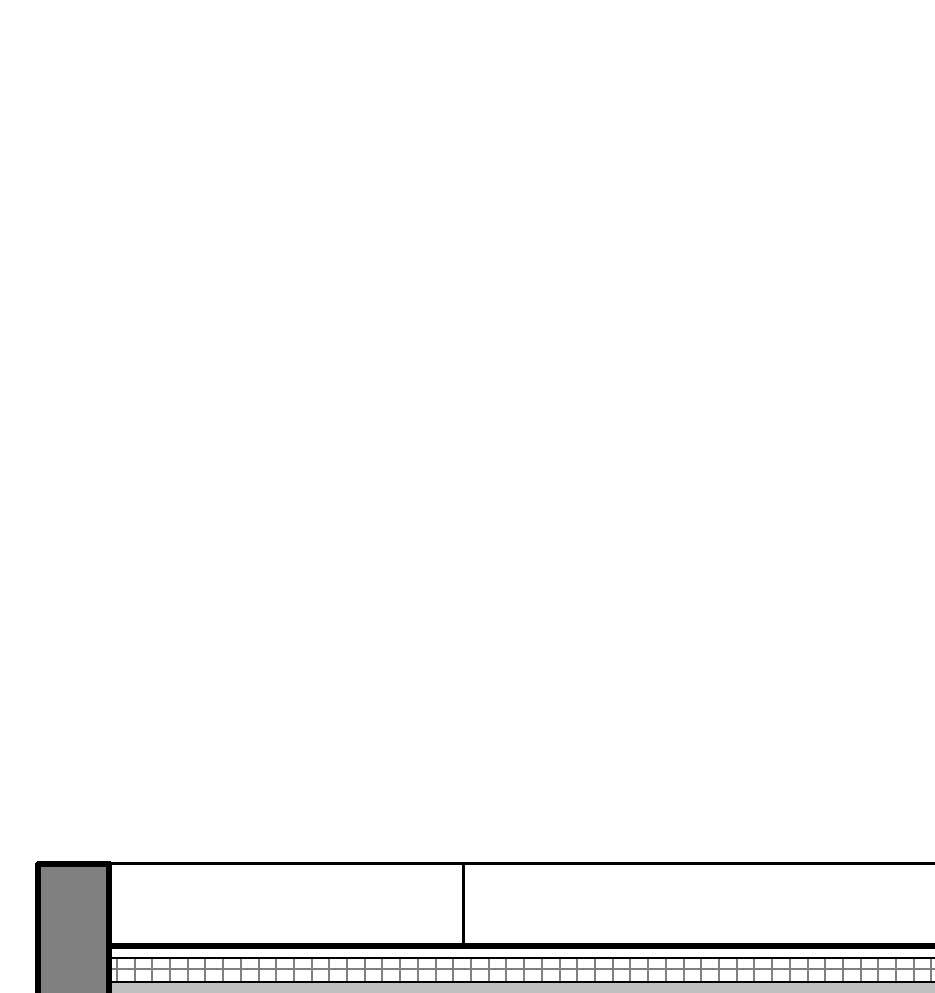
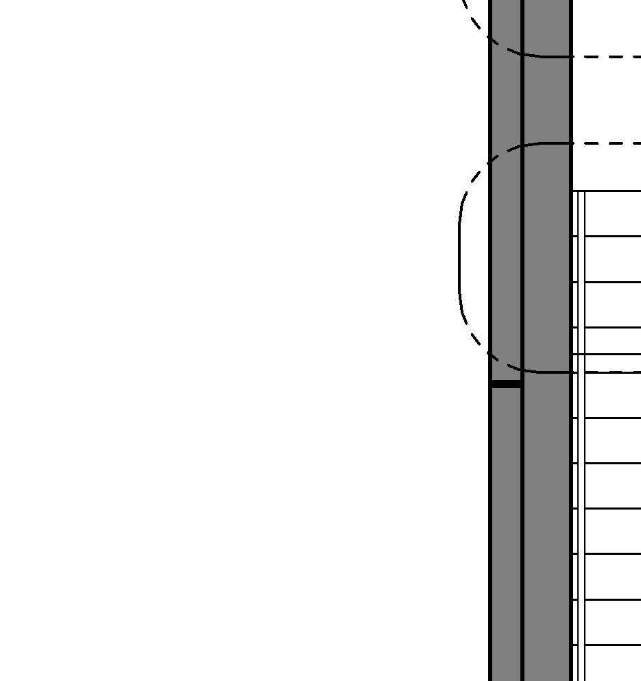
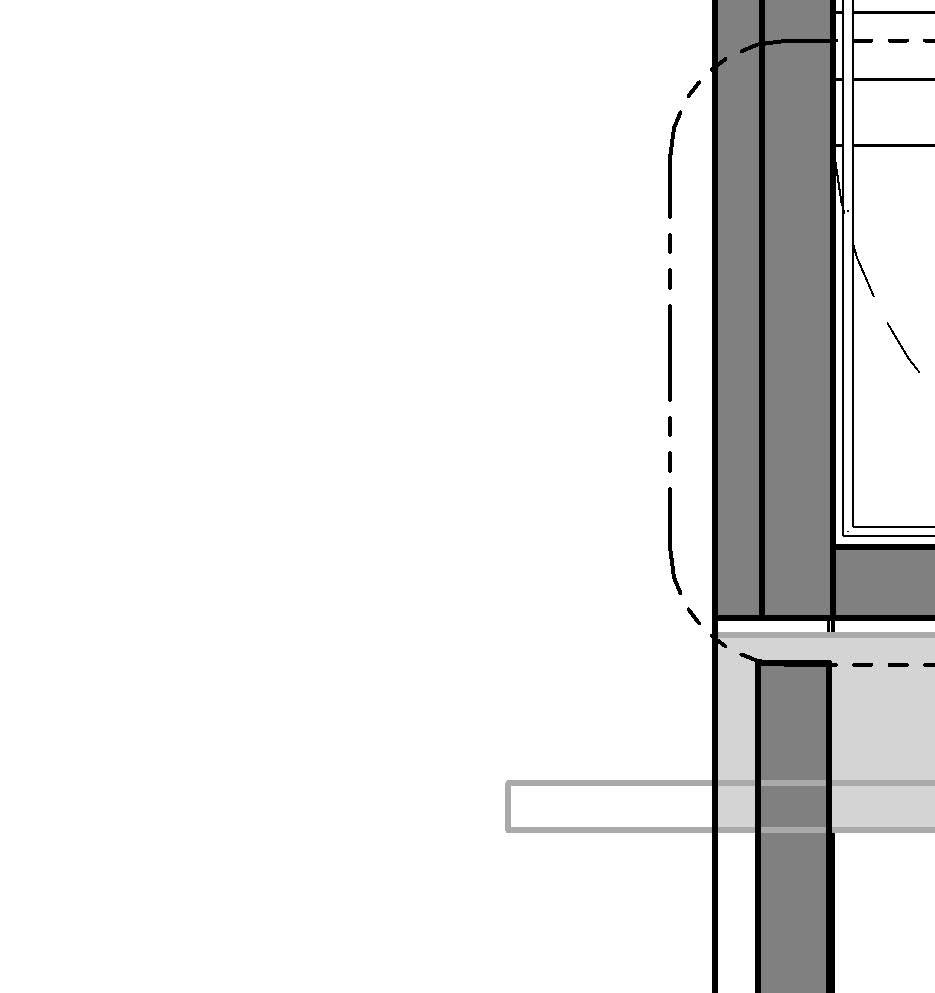
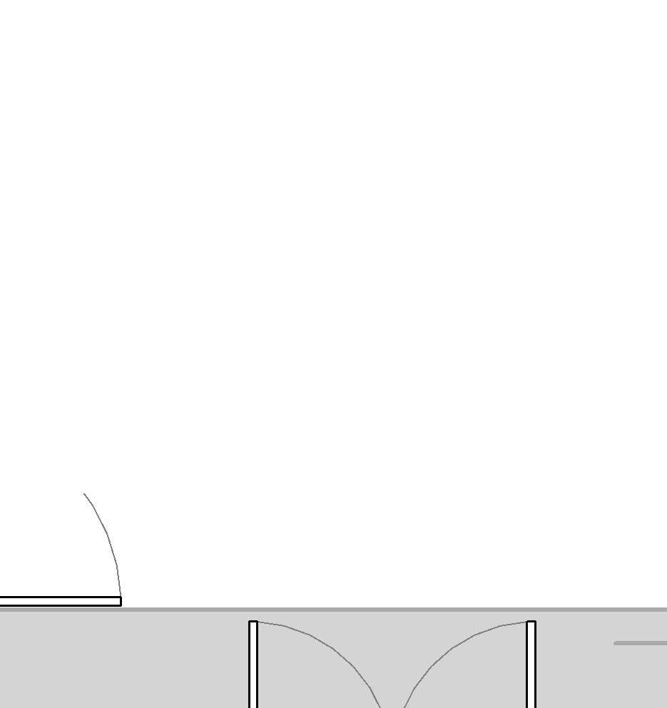
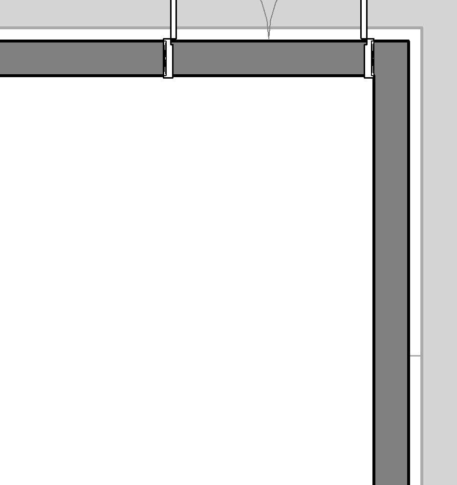
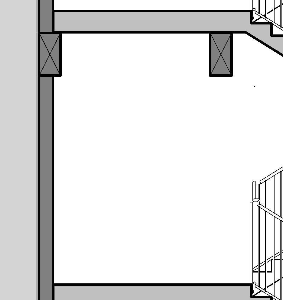
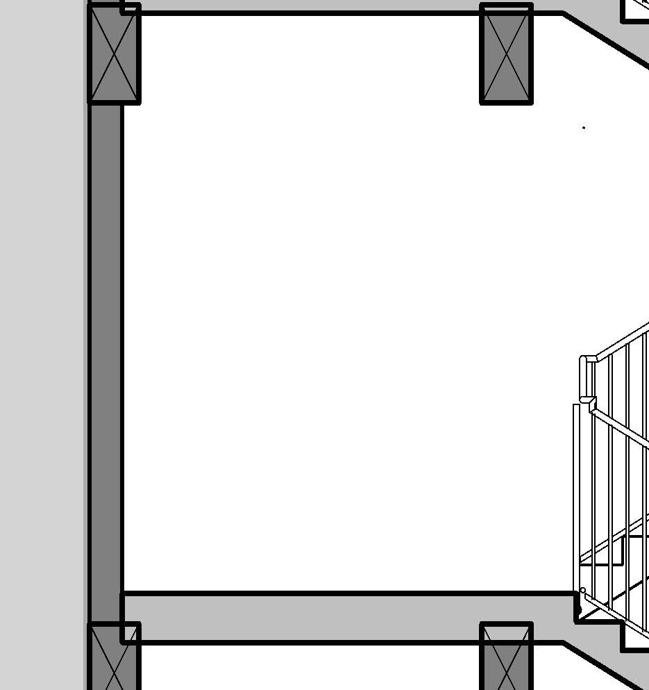
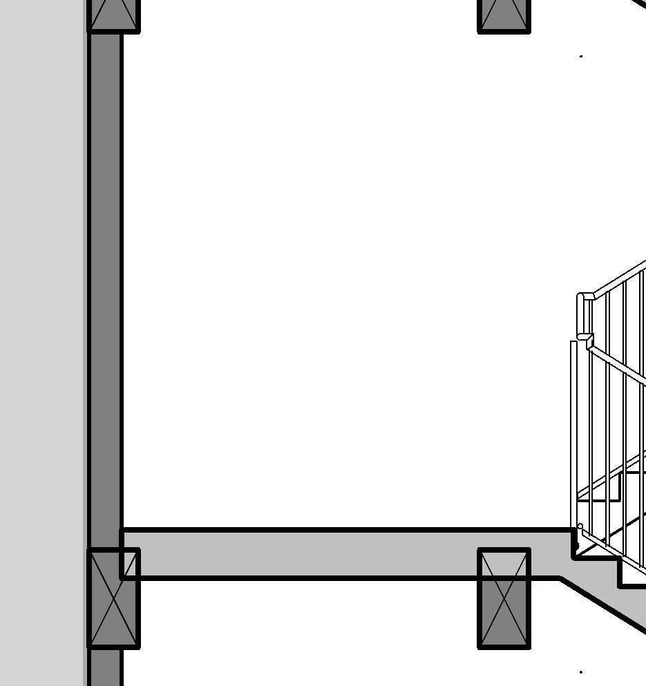
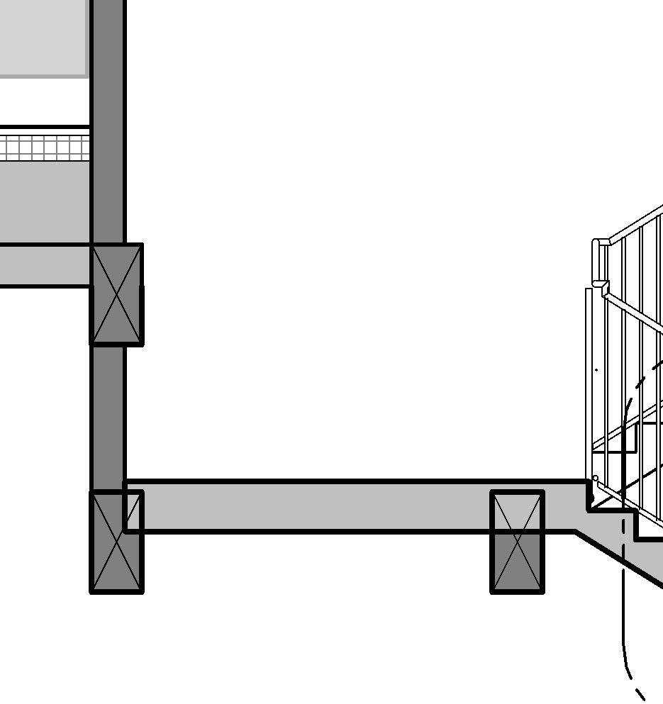
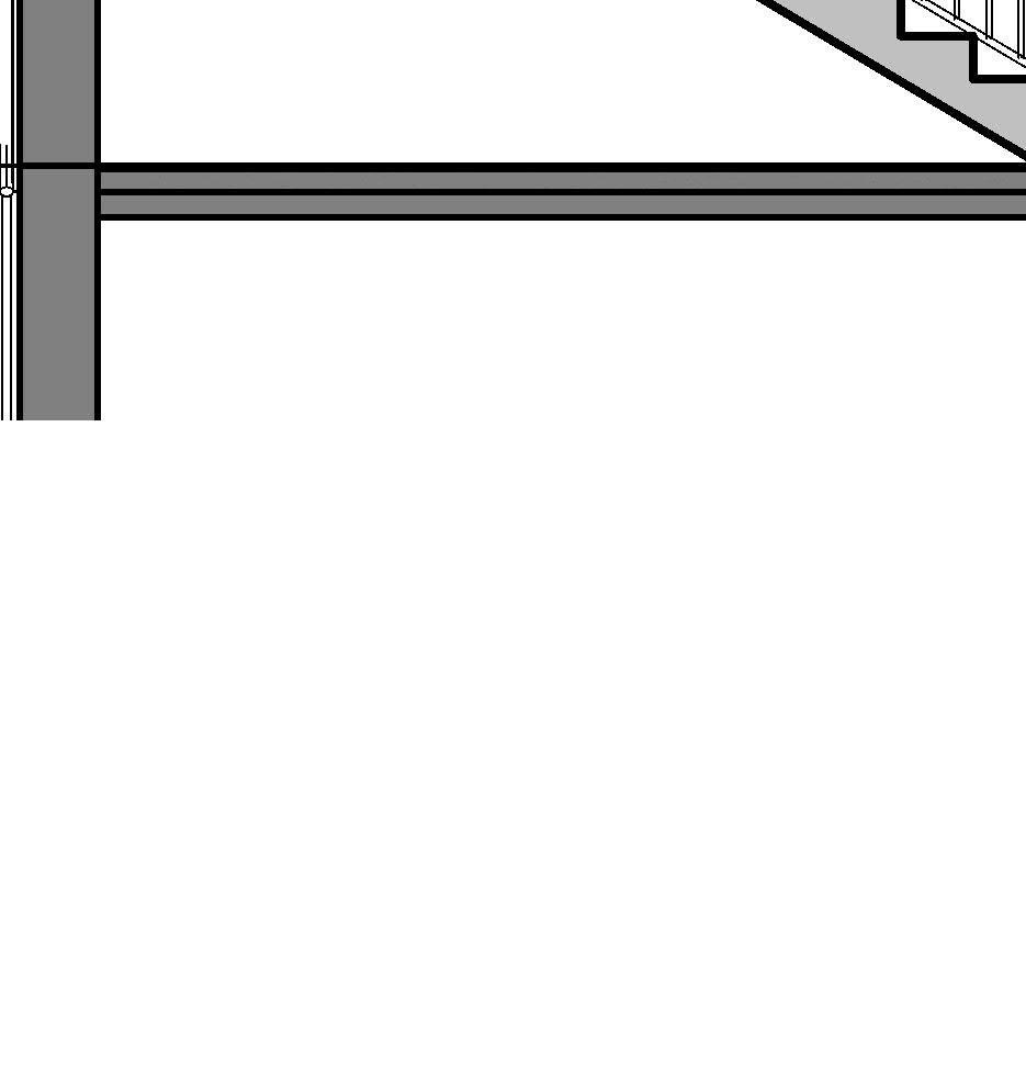
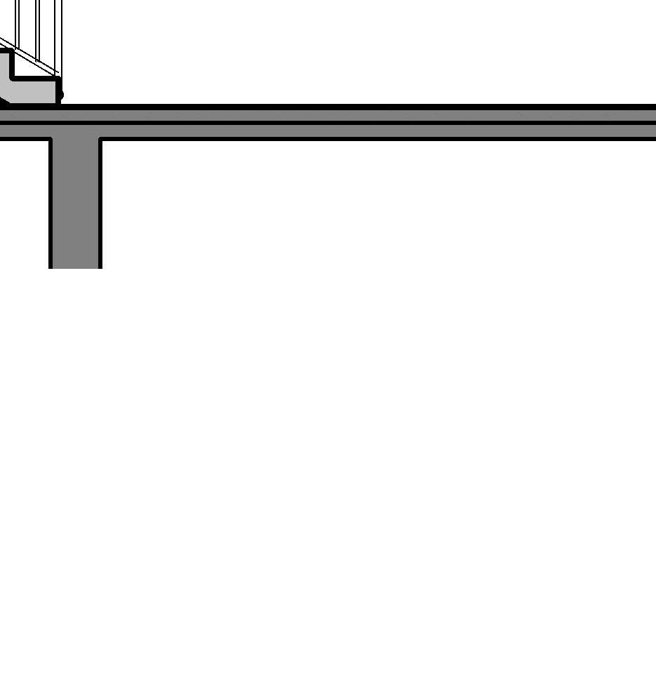
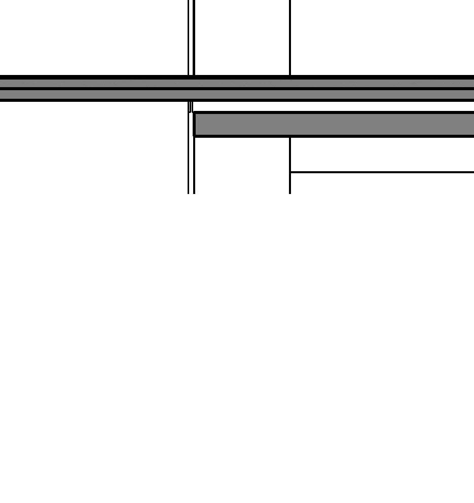
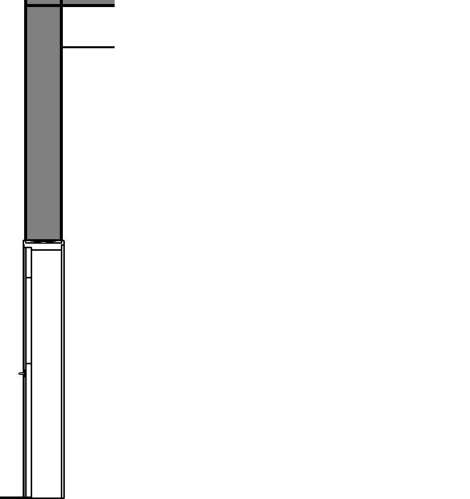
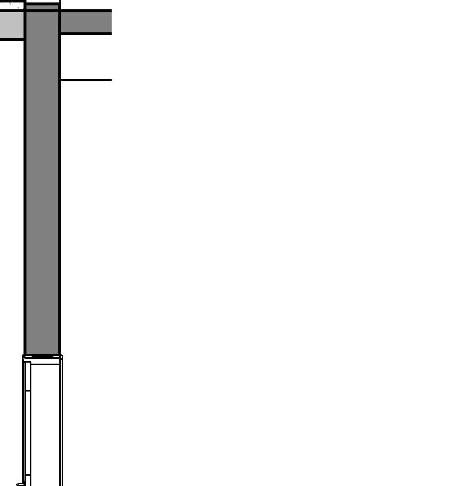
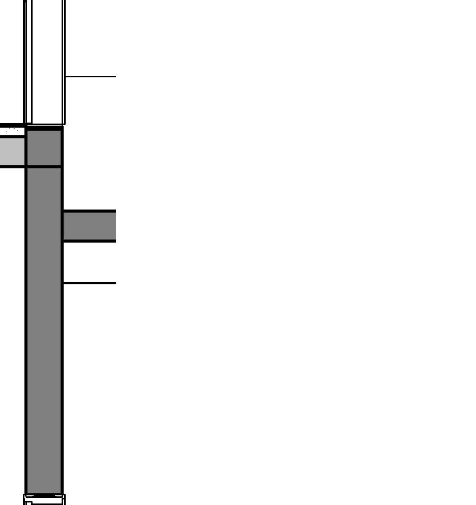
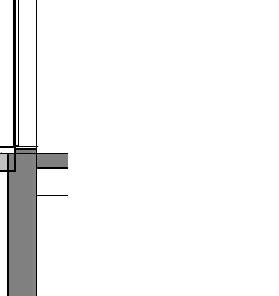
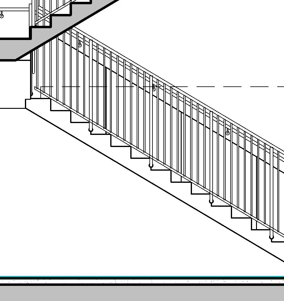
↑ Top of assembled stair, Elevation
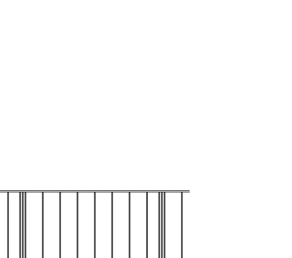
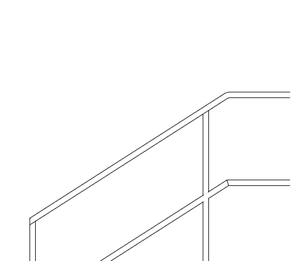
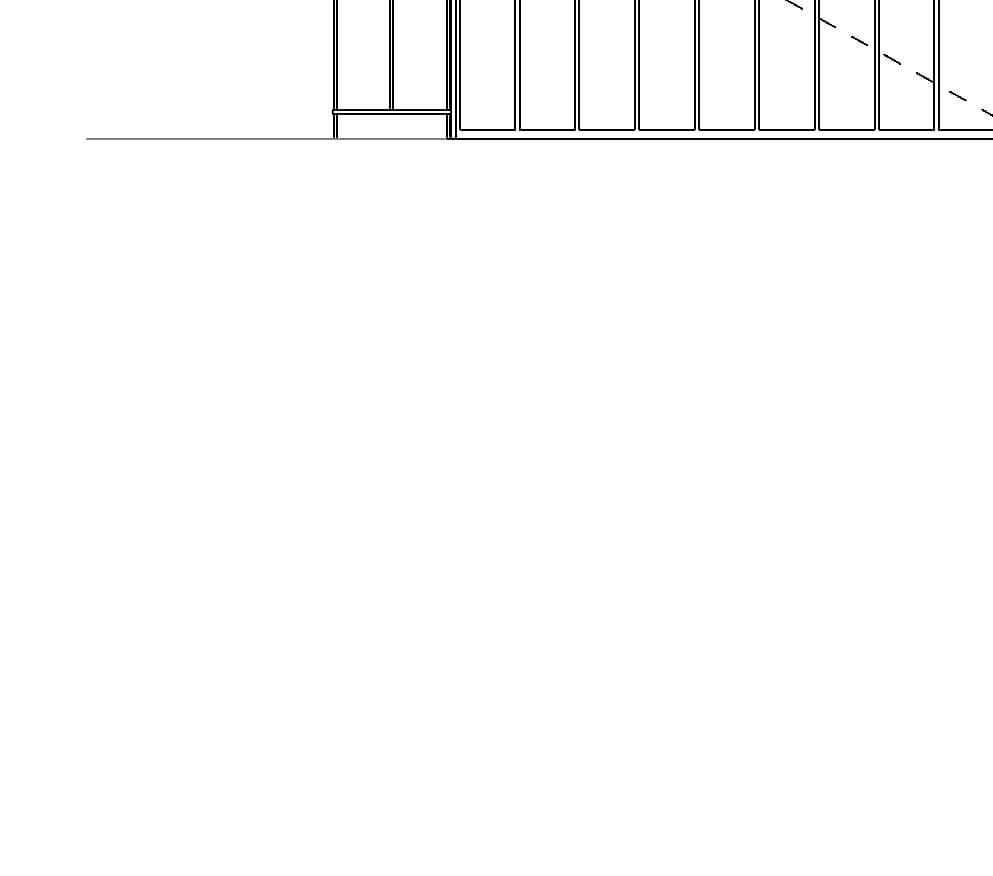
↑ Landing of assembled stair, Elevation

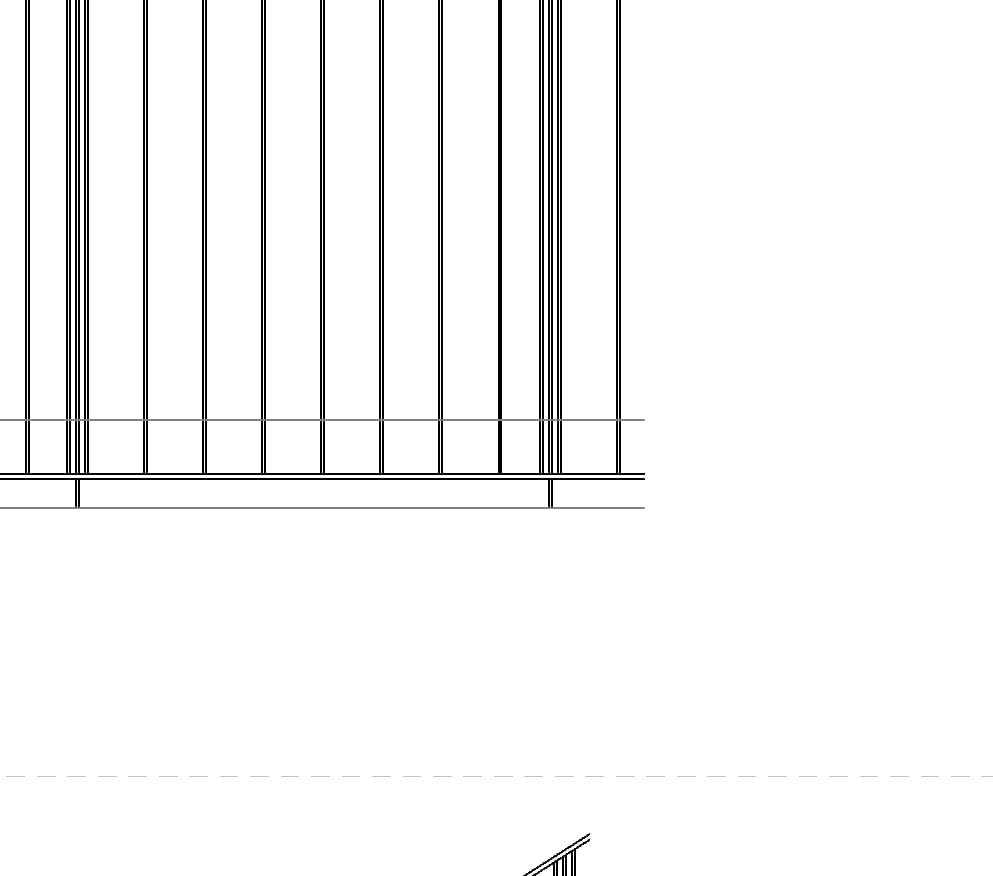
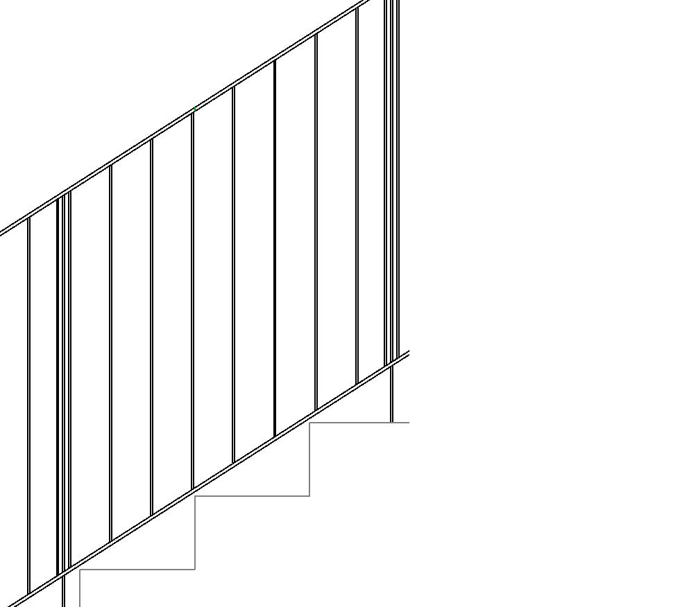
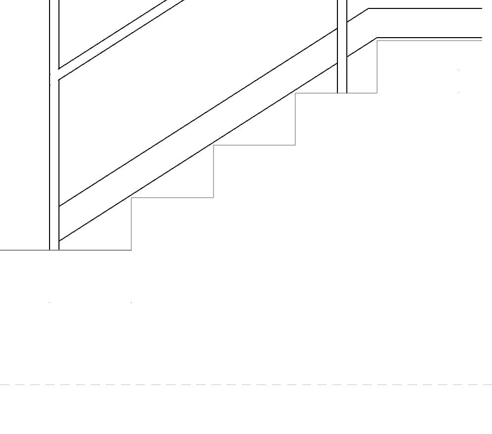
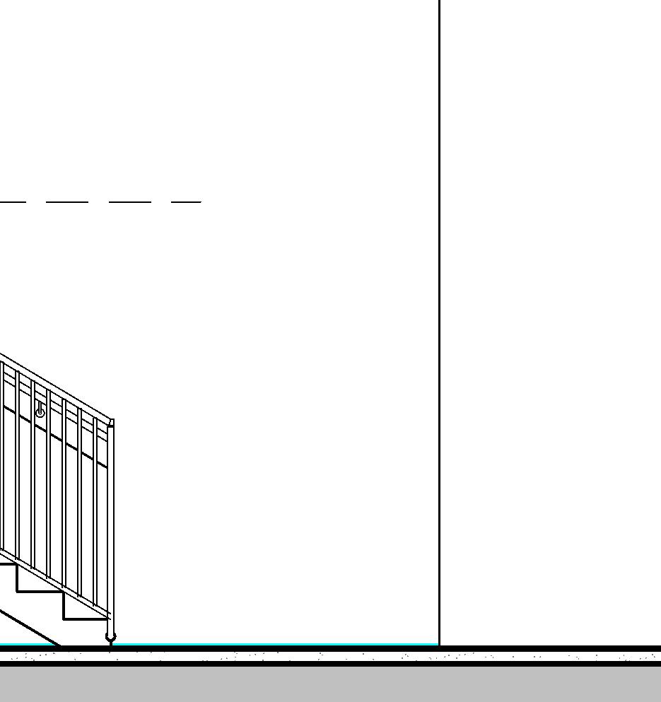
↑ Bottom of assembled stair, Elevation
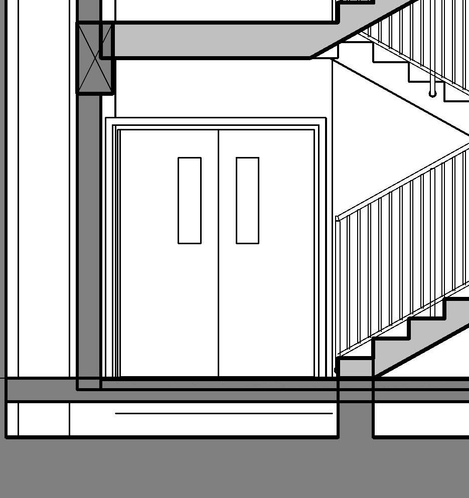
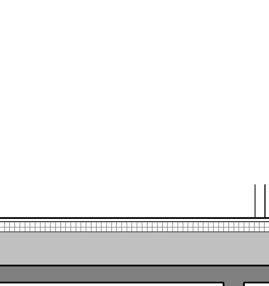
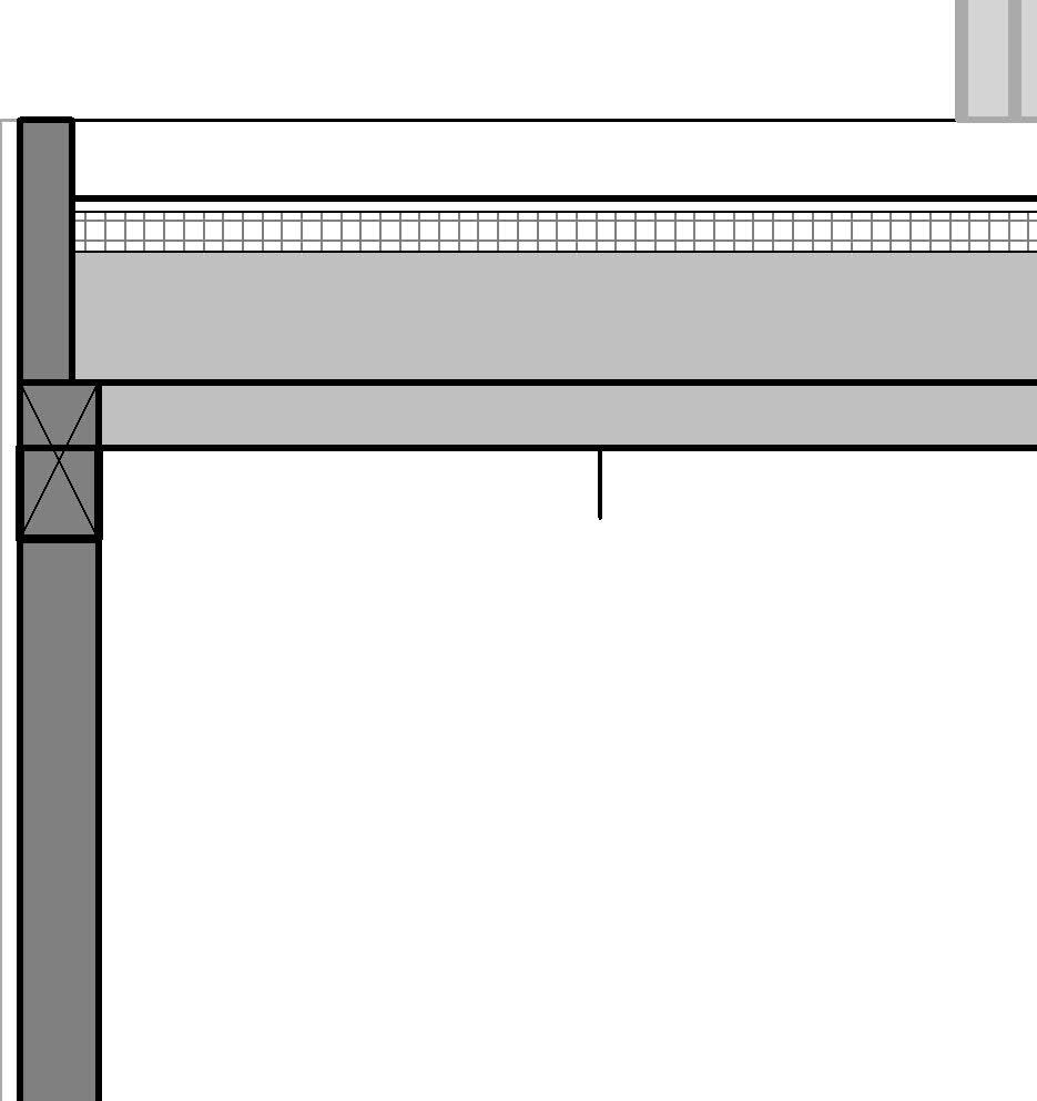
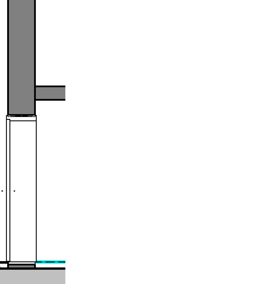
6.2 Cast-in-place Stair what are my options?
what are my options?
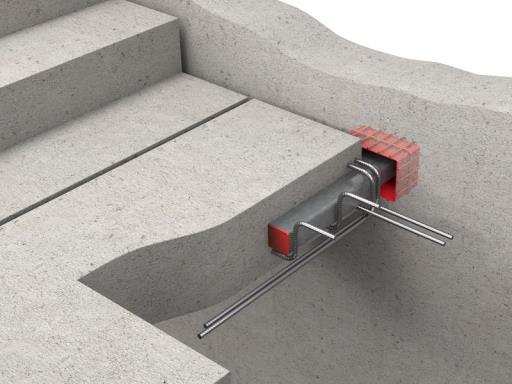
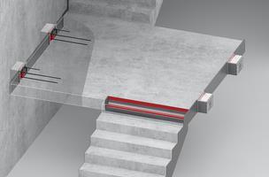
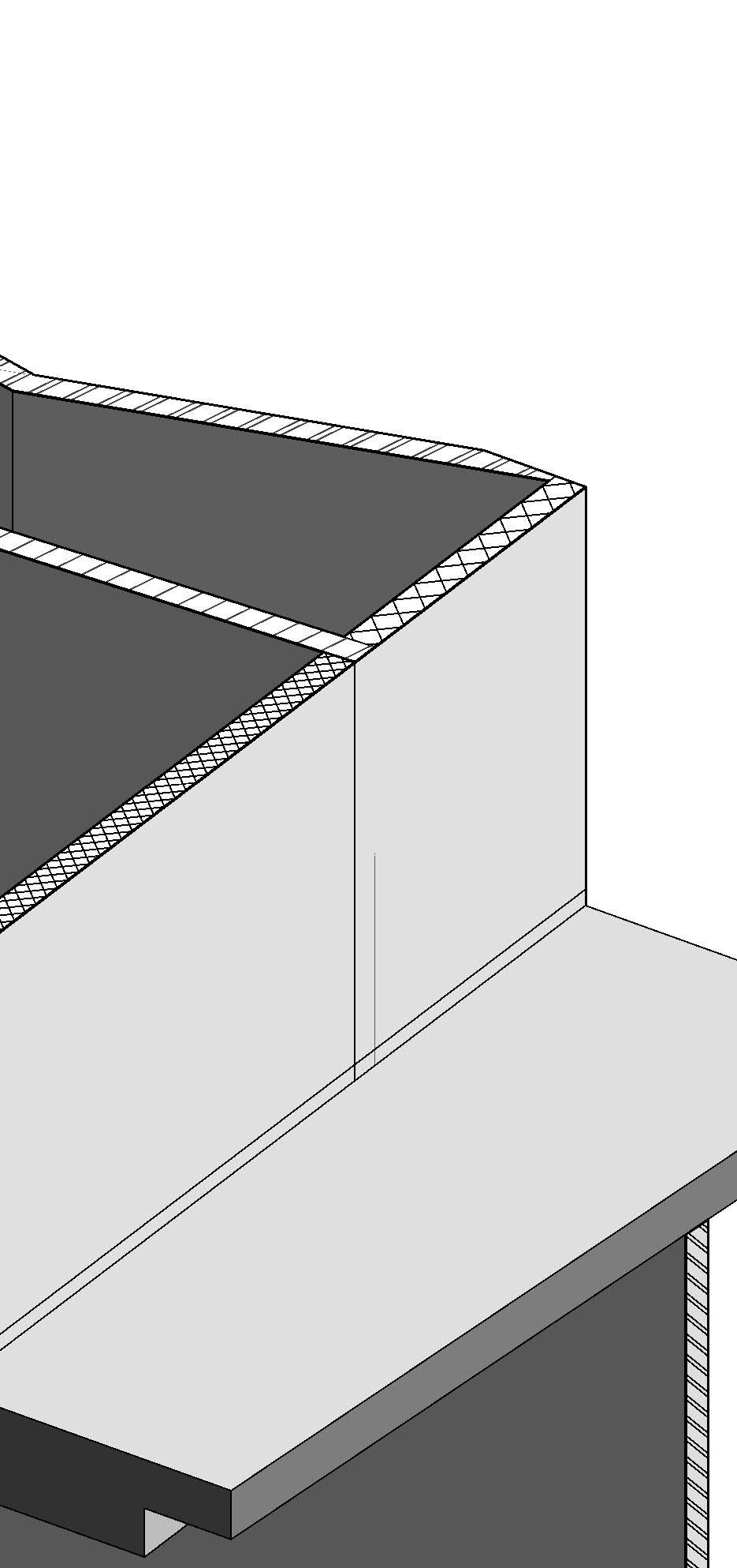
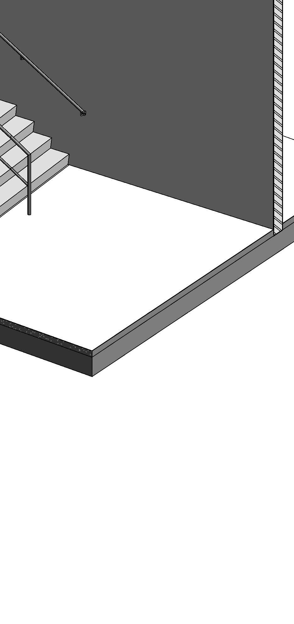
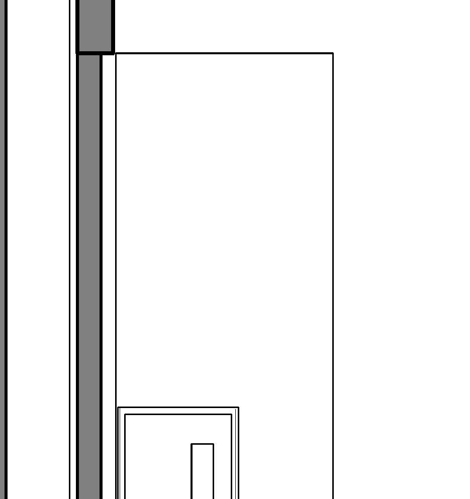
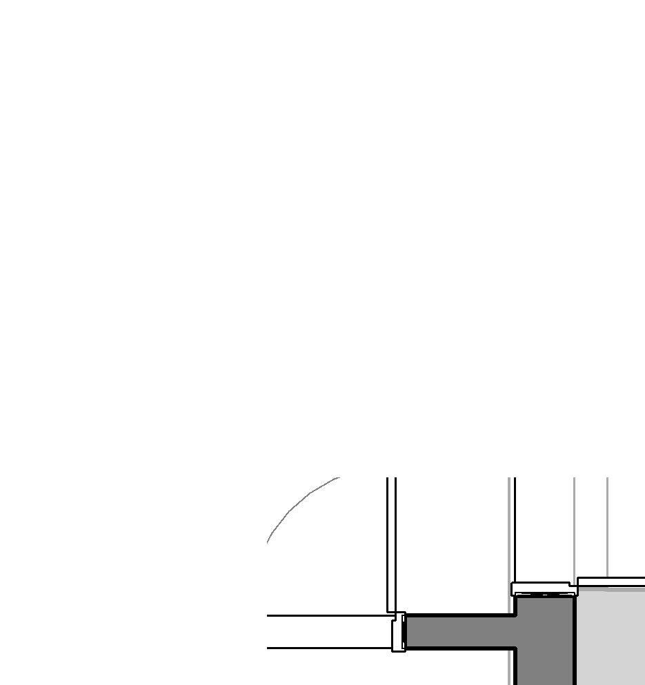
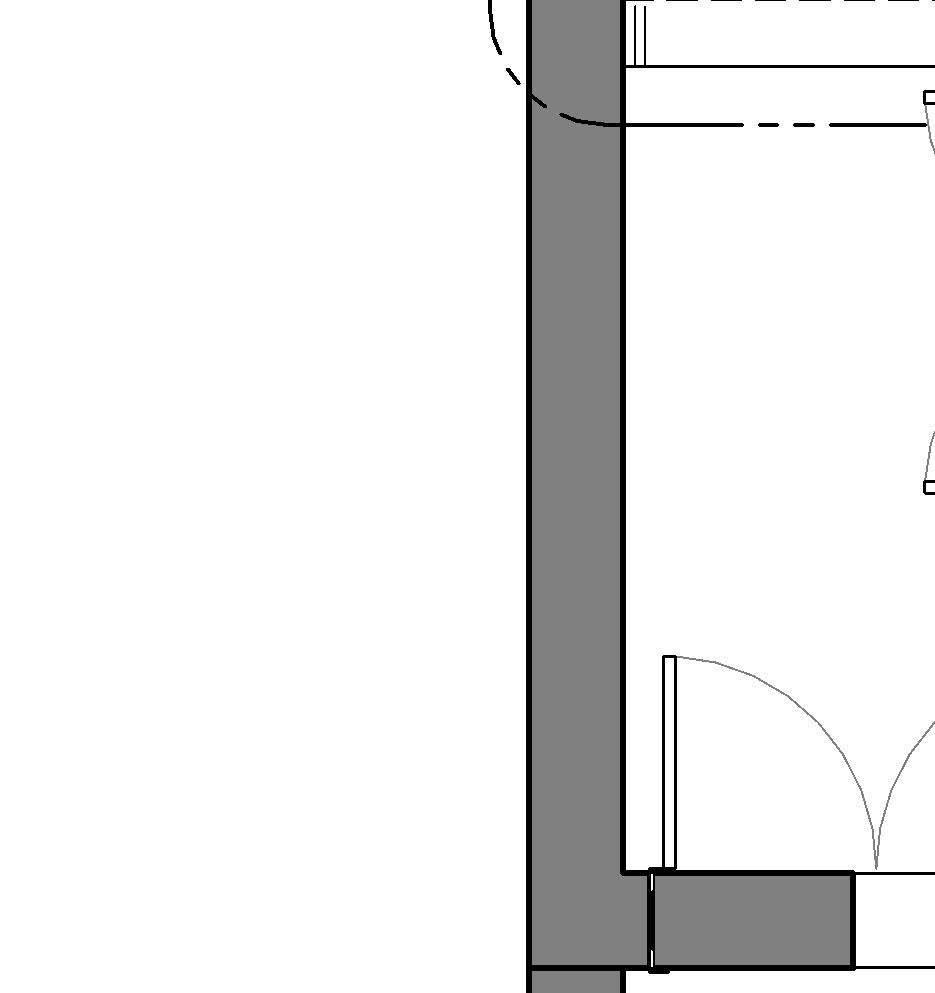
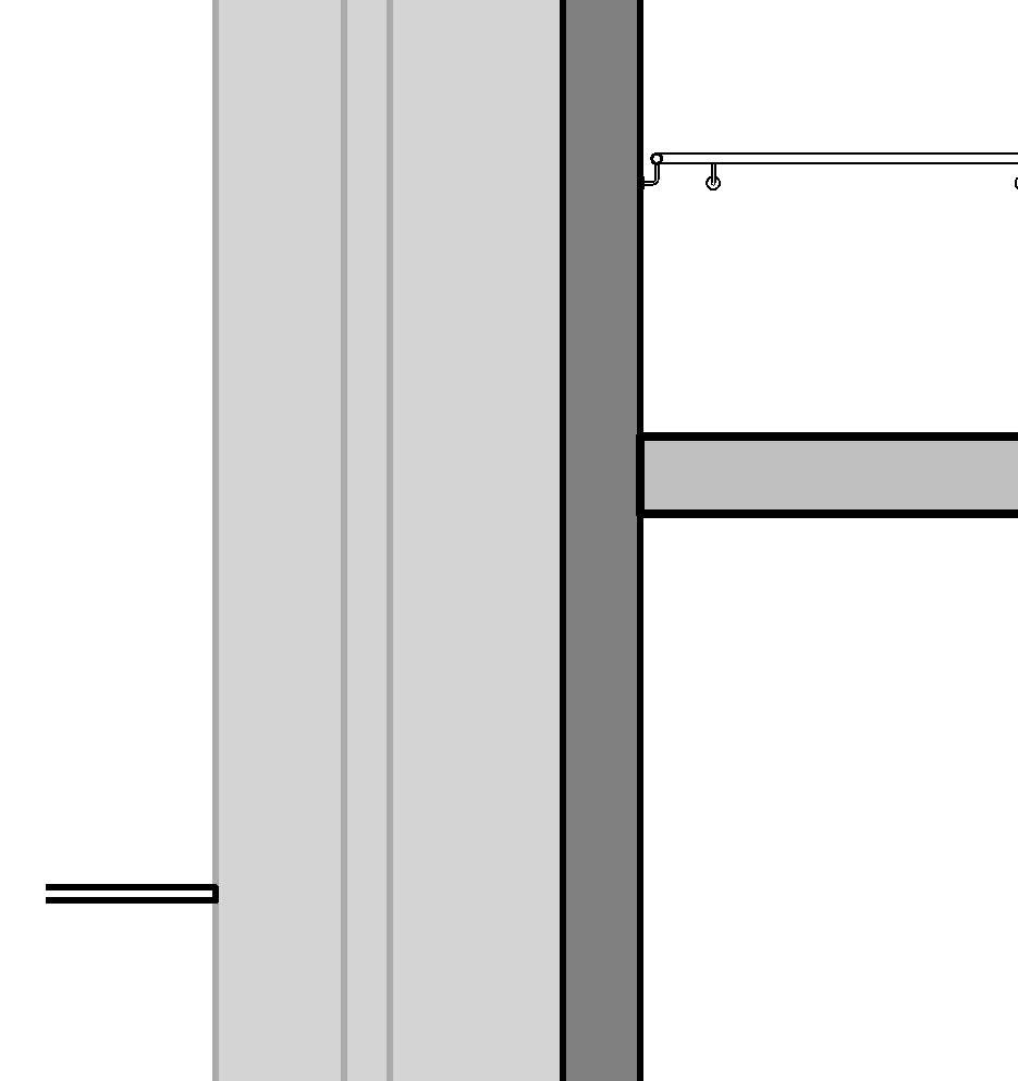
↑ Concrete Precast Stair bottom landing for Barracks facilty
Important: Bear in mind the acoustic connections and rubber bands between pieces in precast stairs
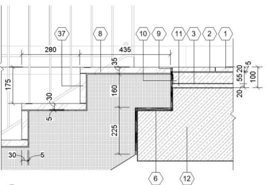
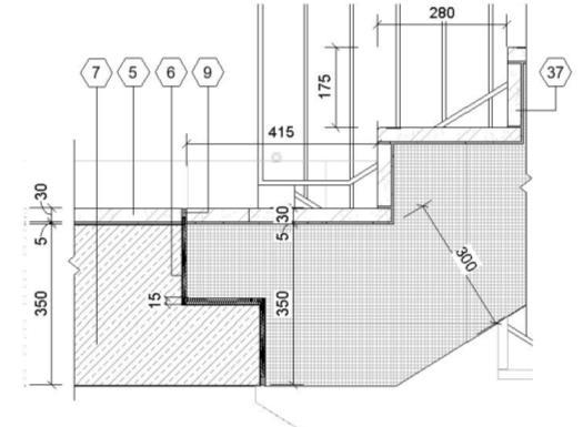
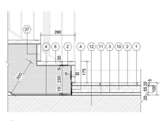
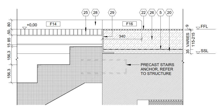
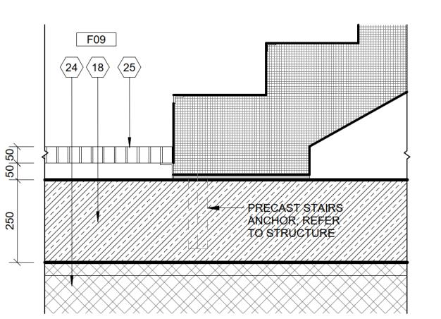
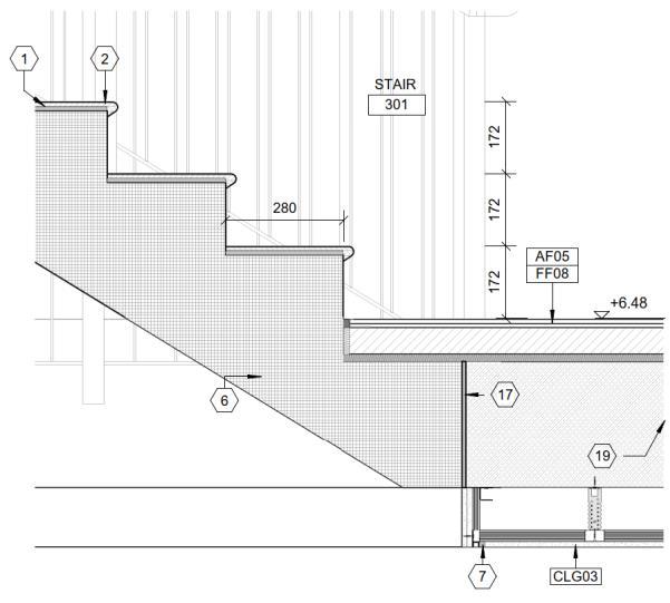
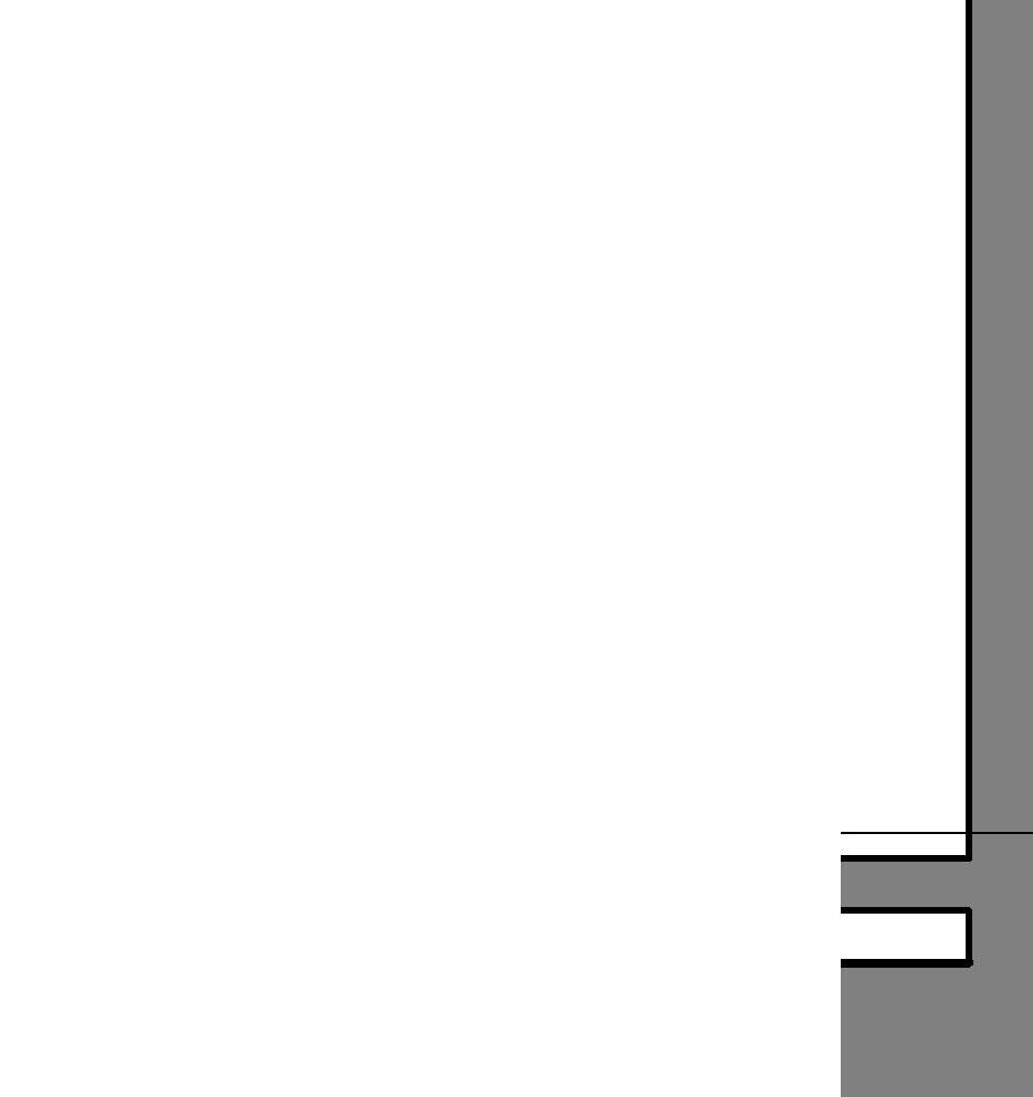
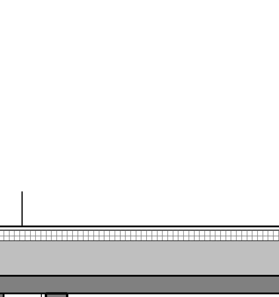
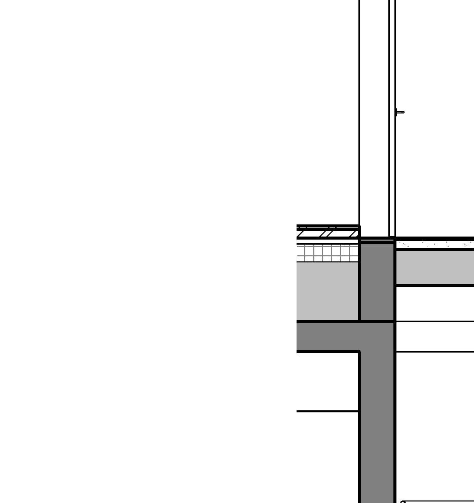
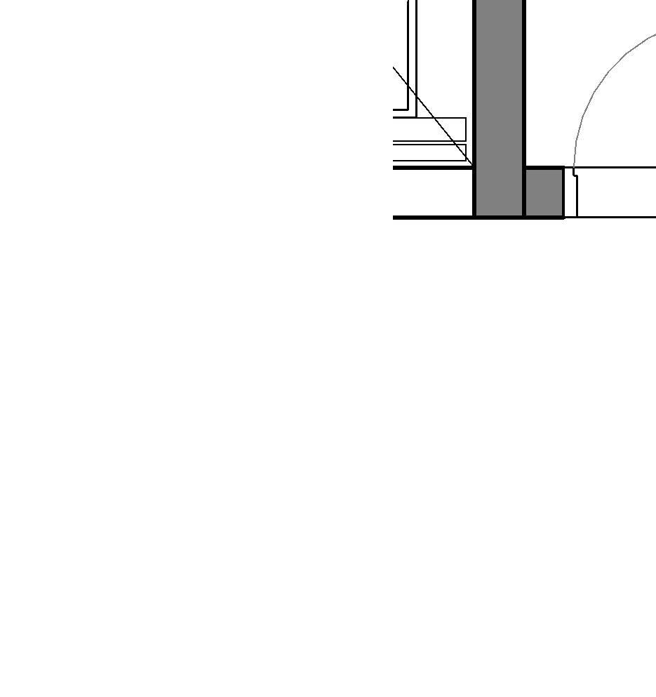
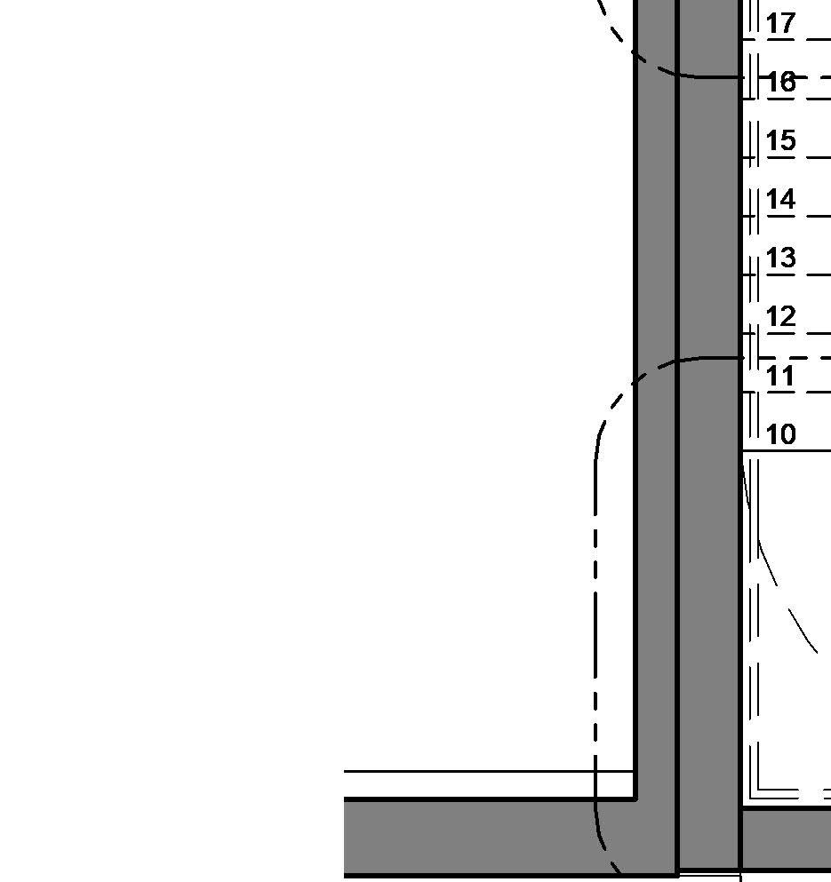
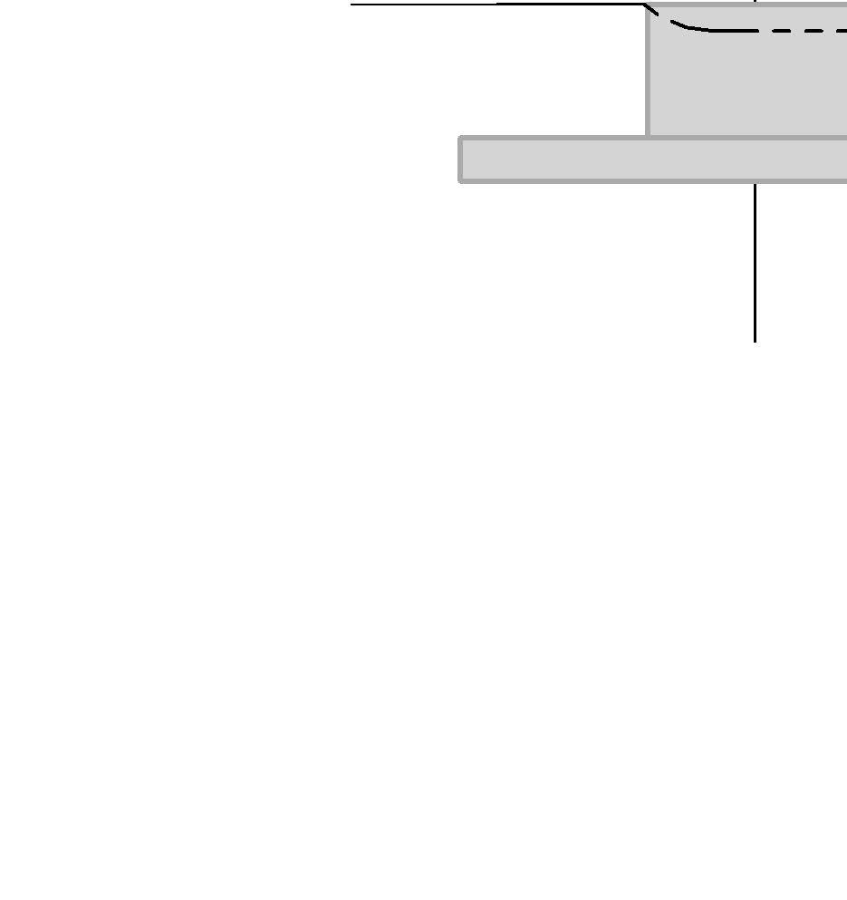
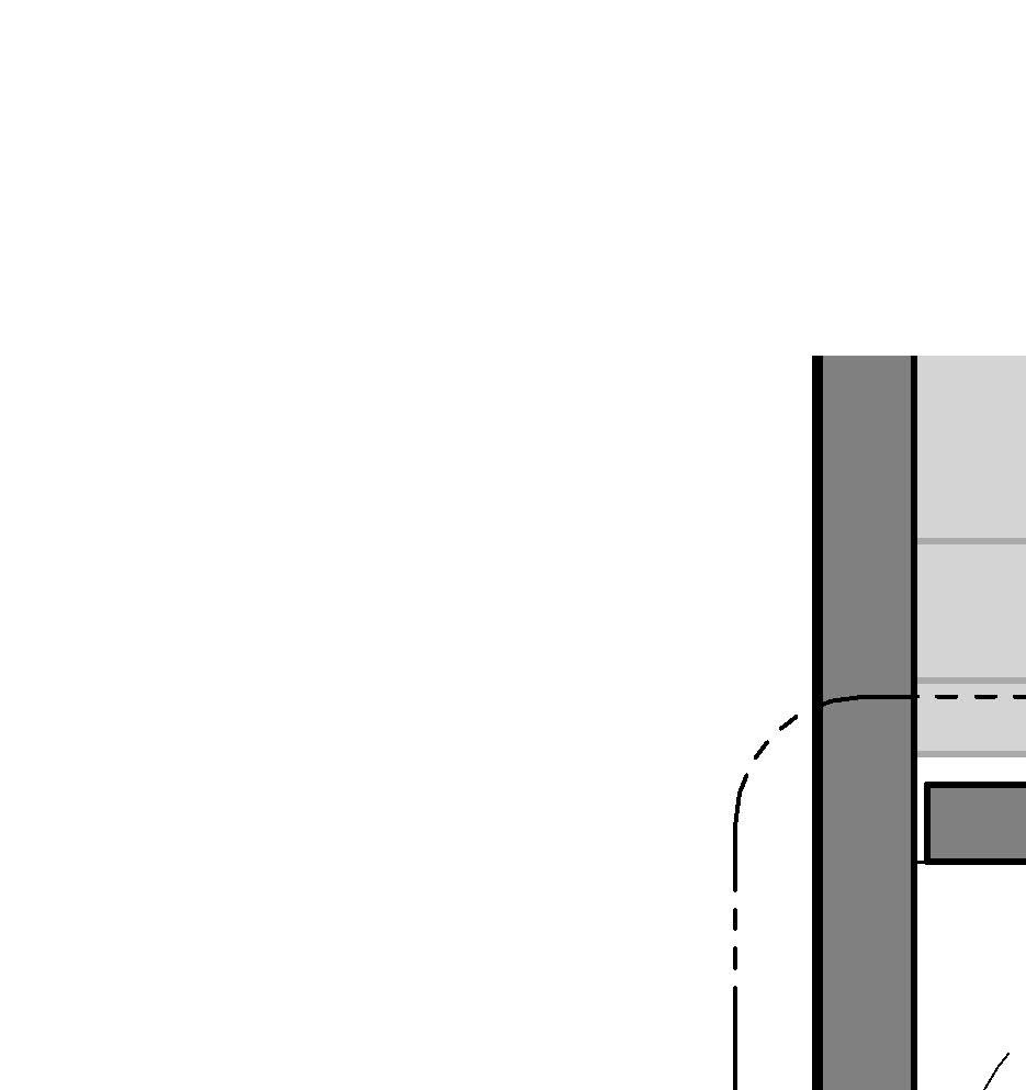
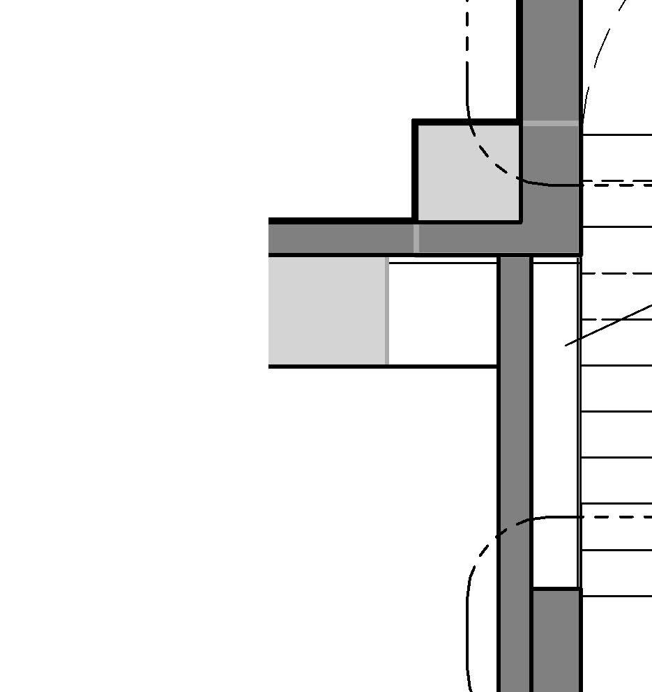
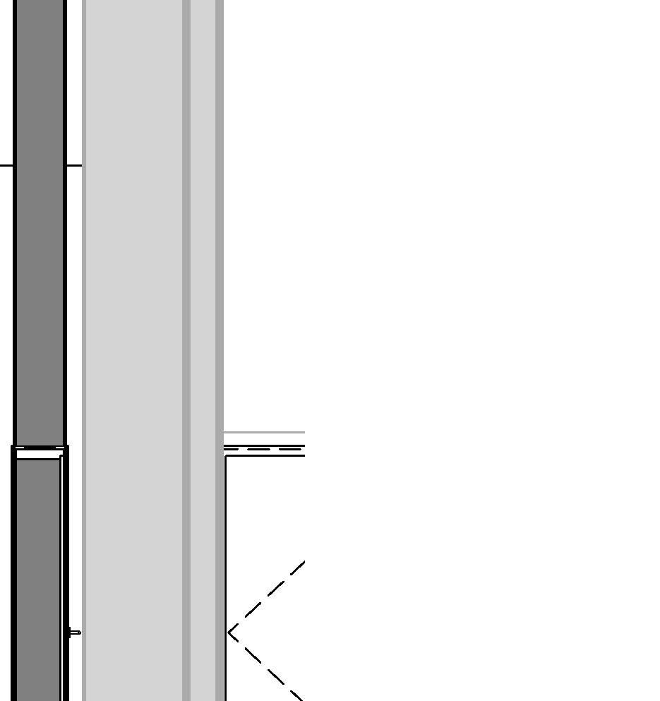
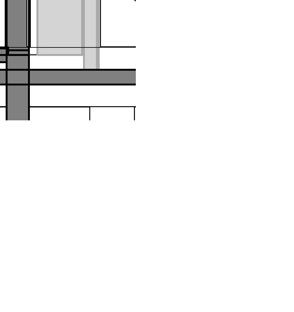
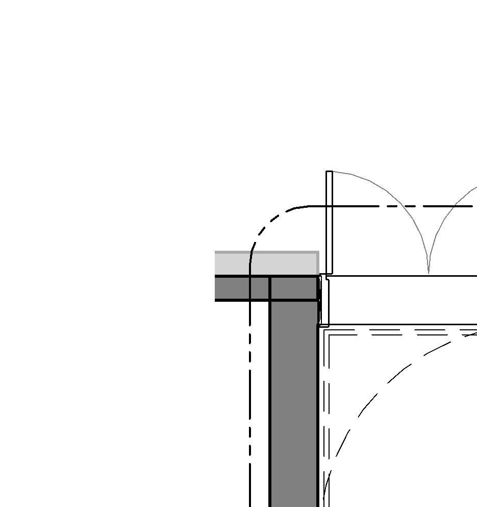
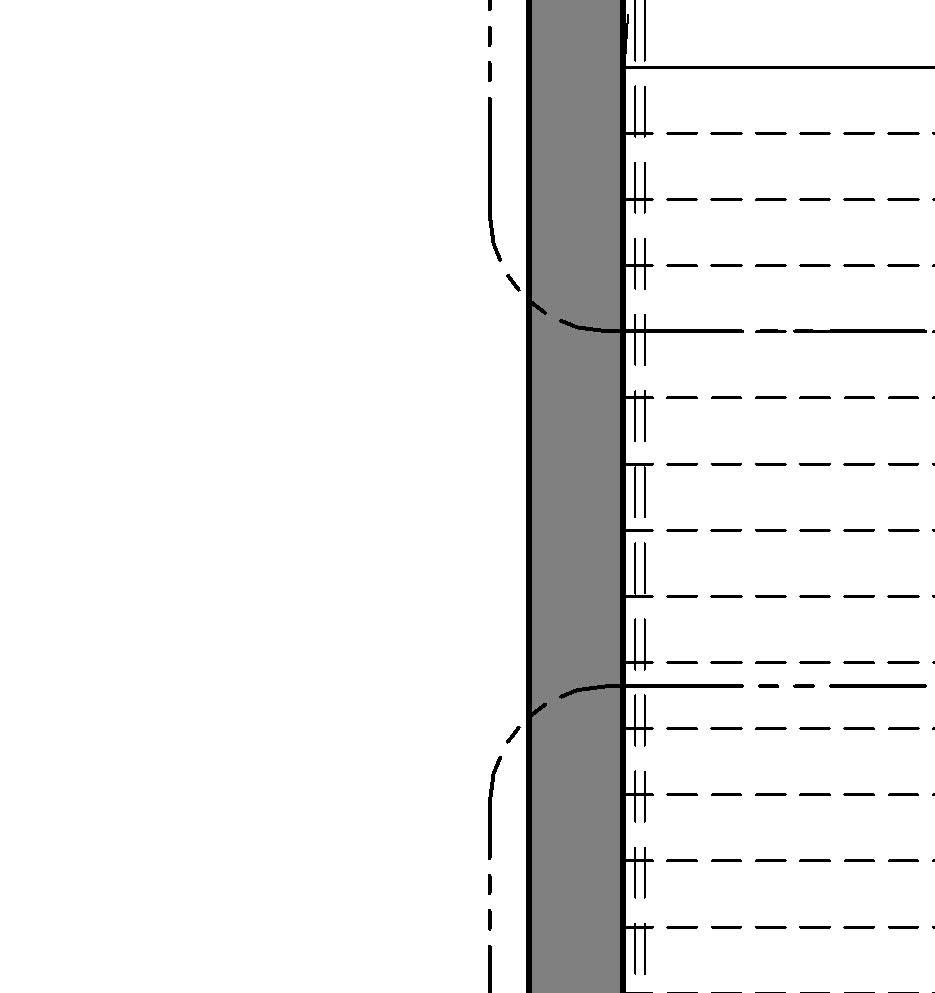
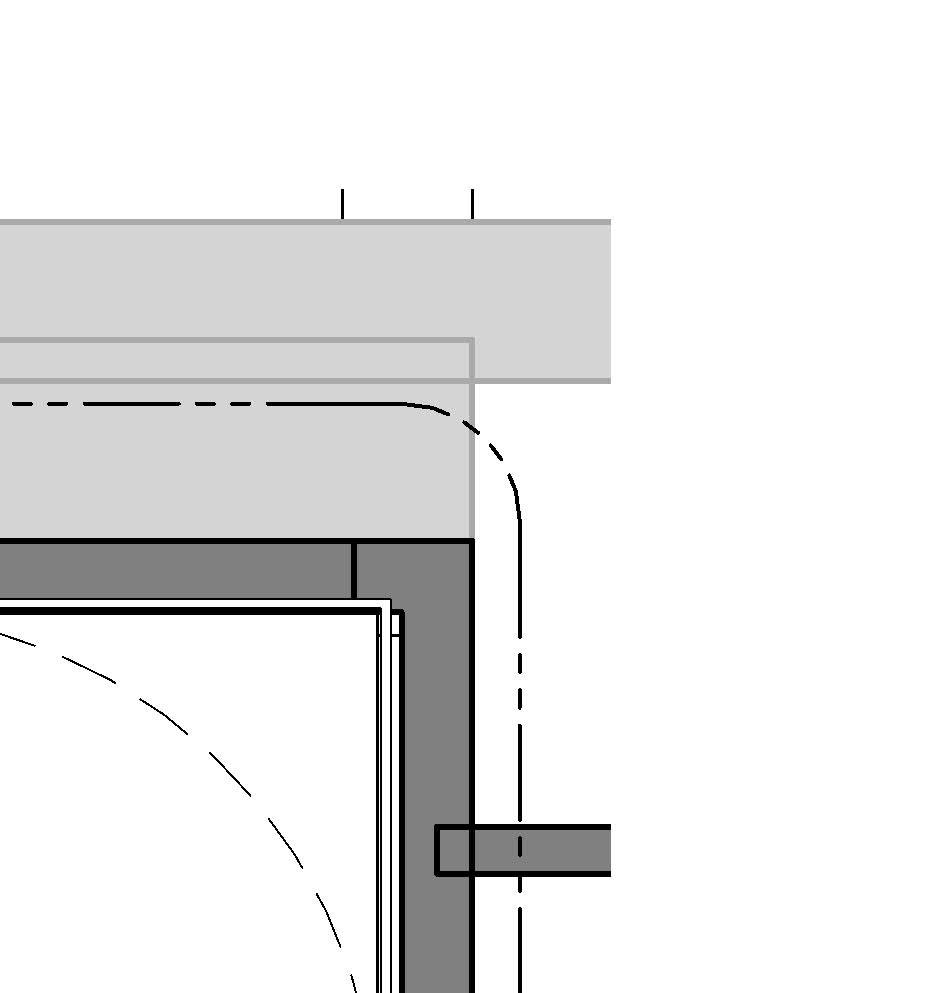
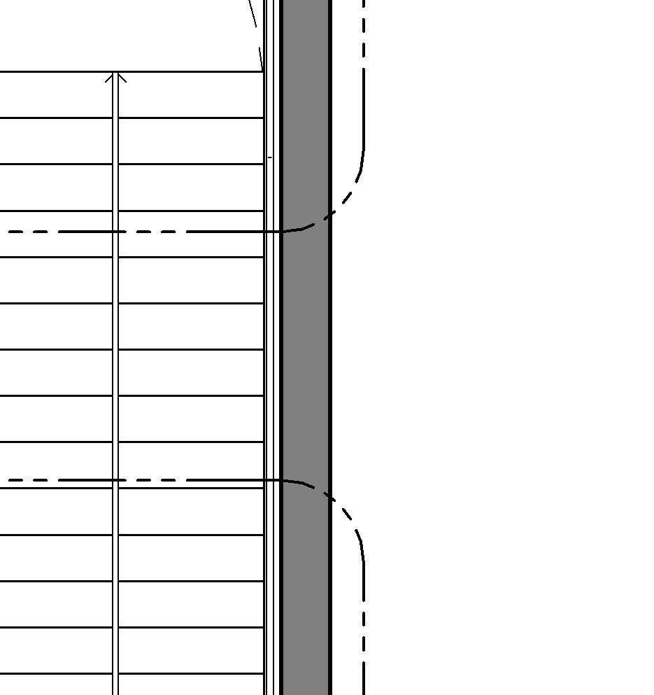
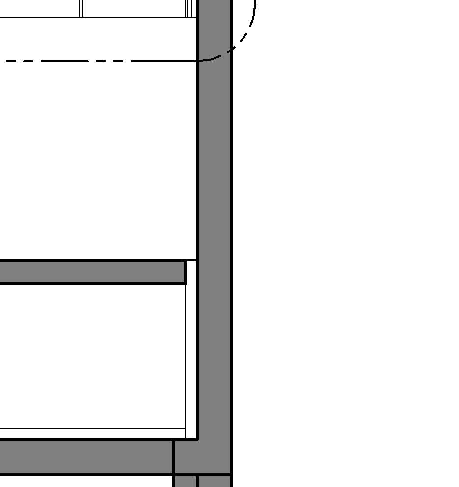
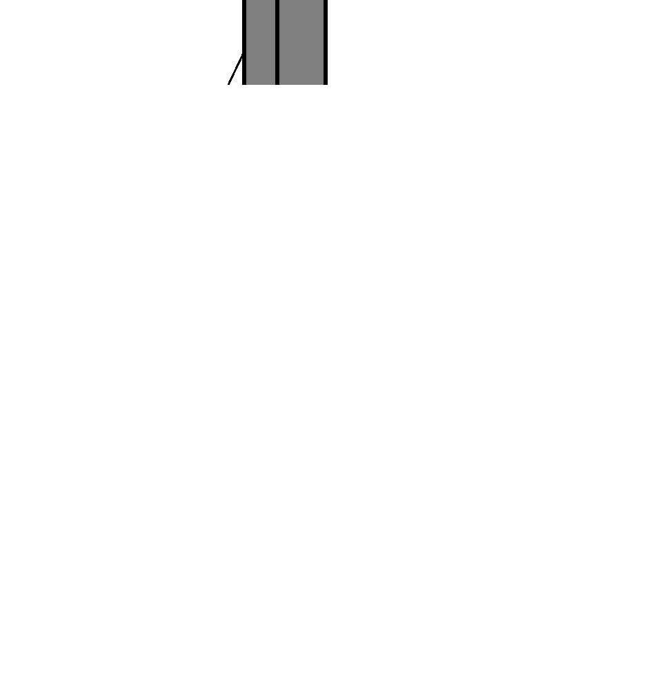
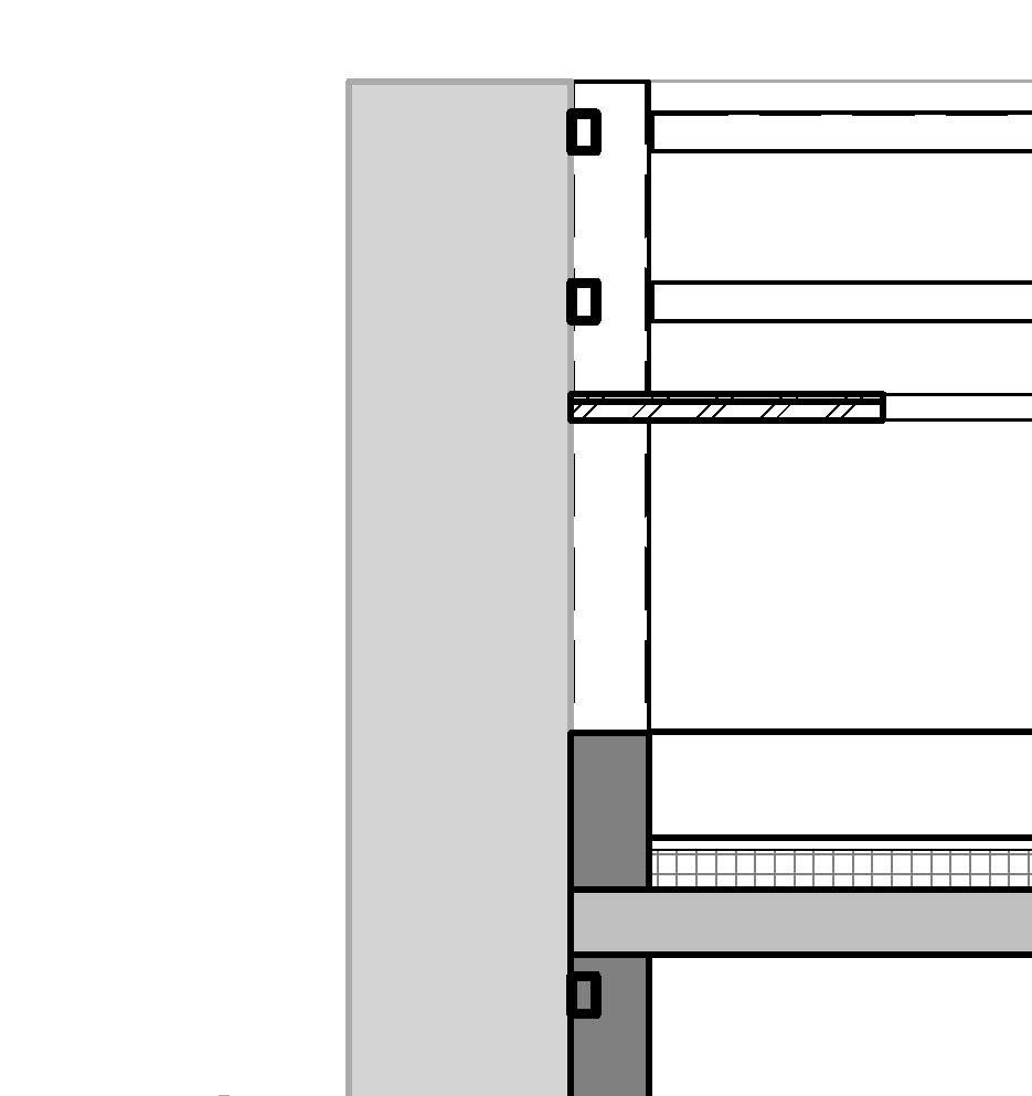
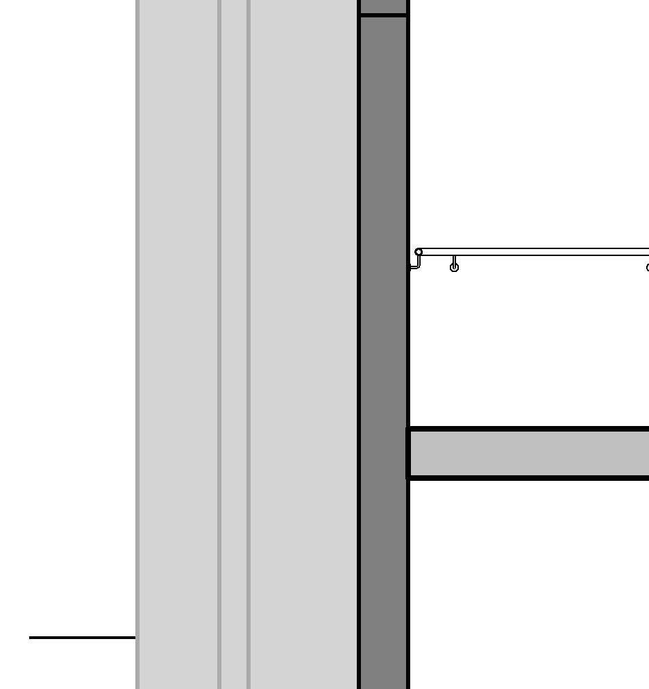
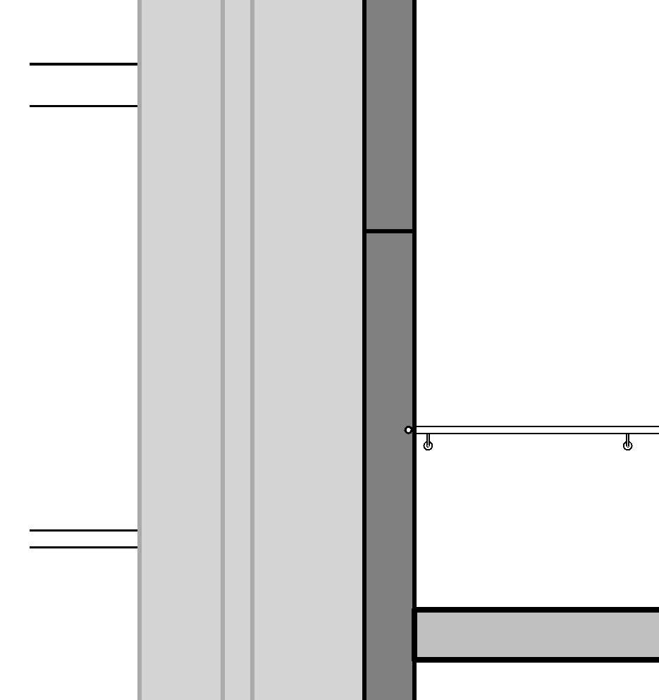
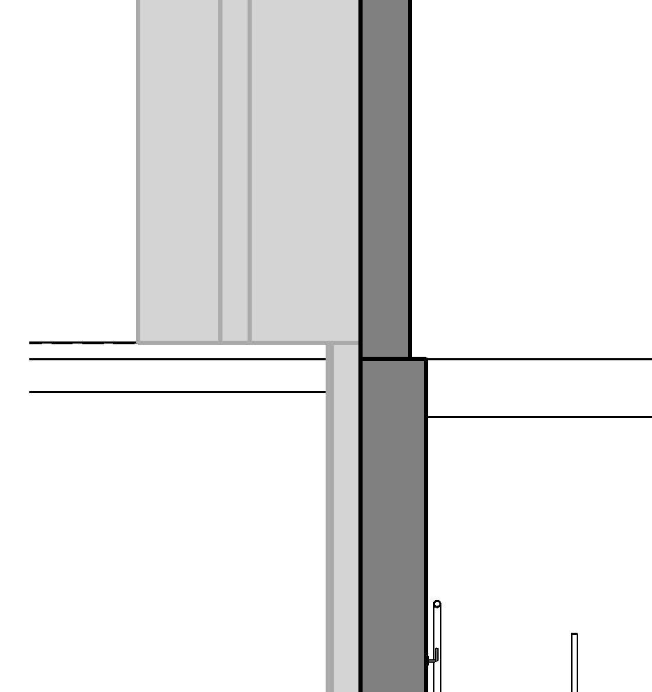
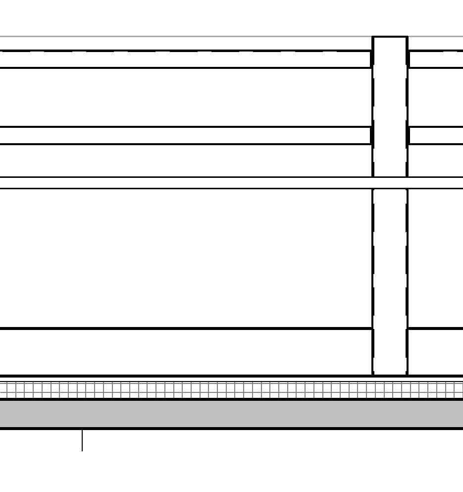
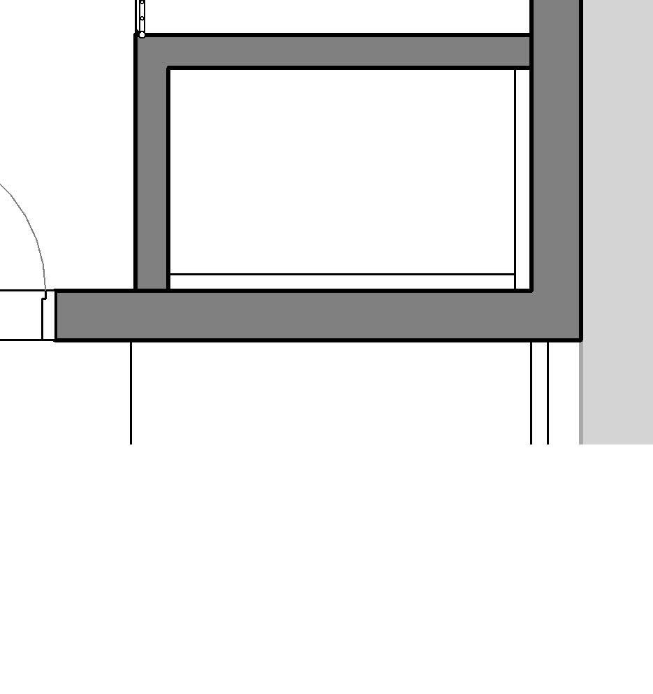
← Concrete Precast Stair top landing, Section detail at 1:10
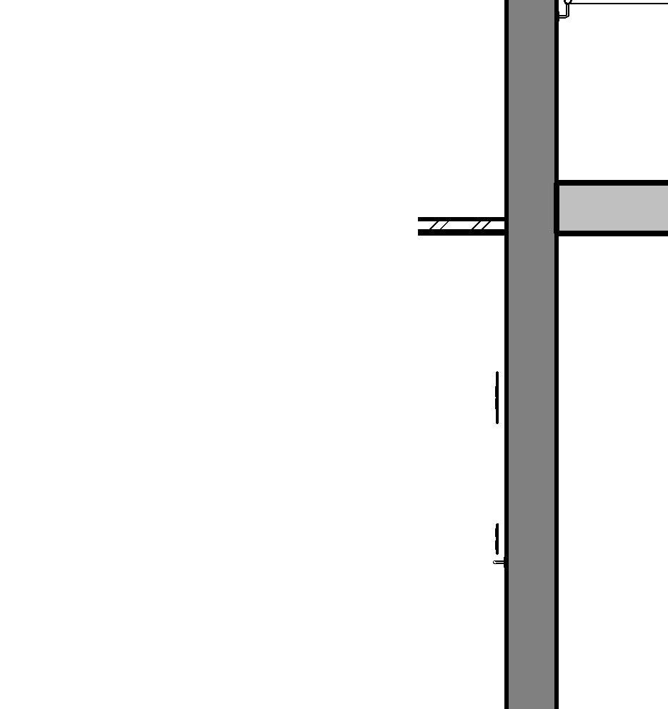
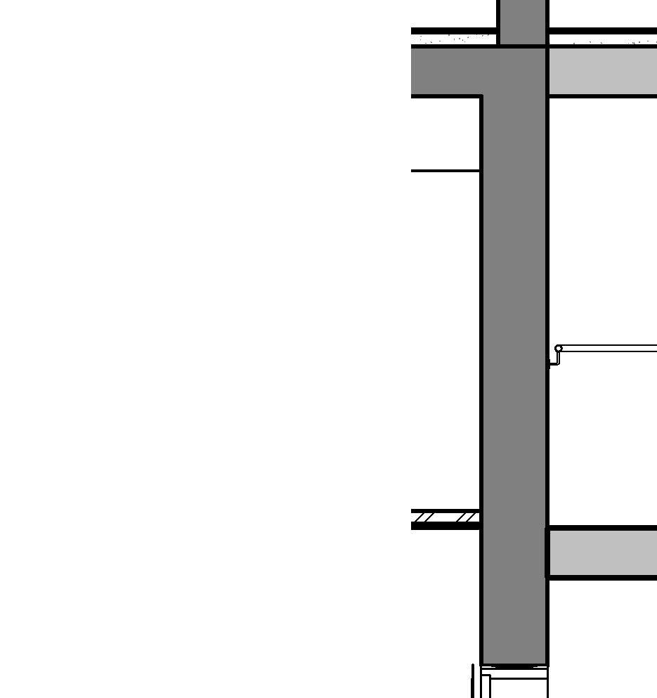
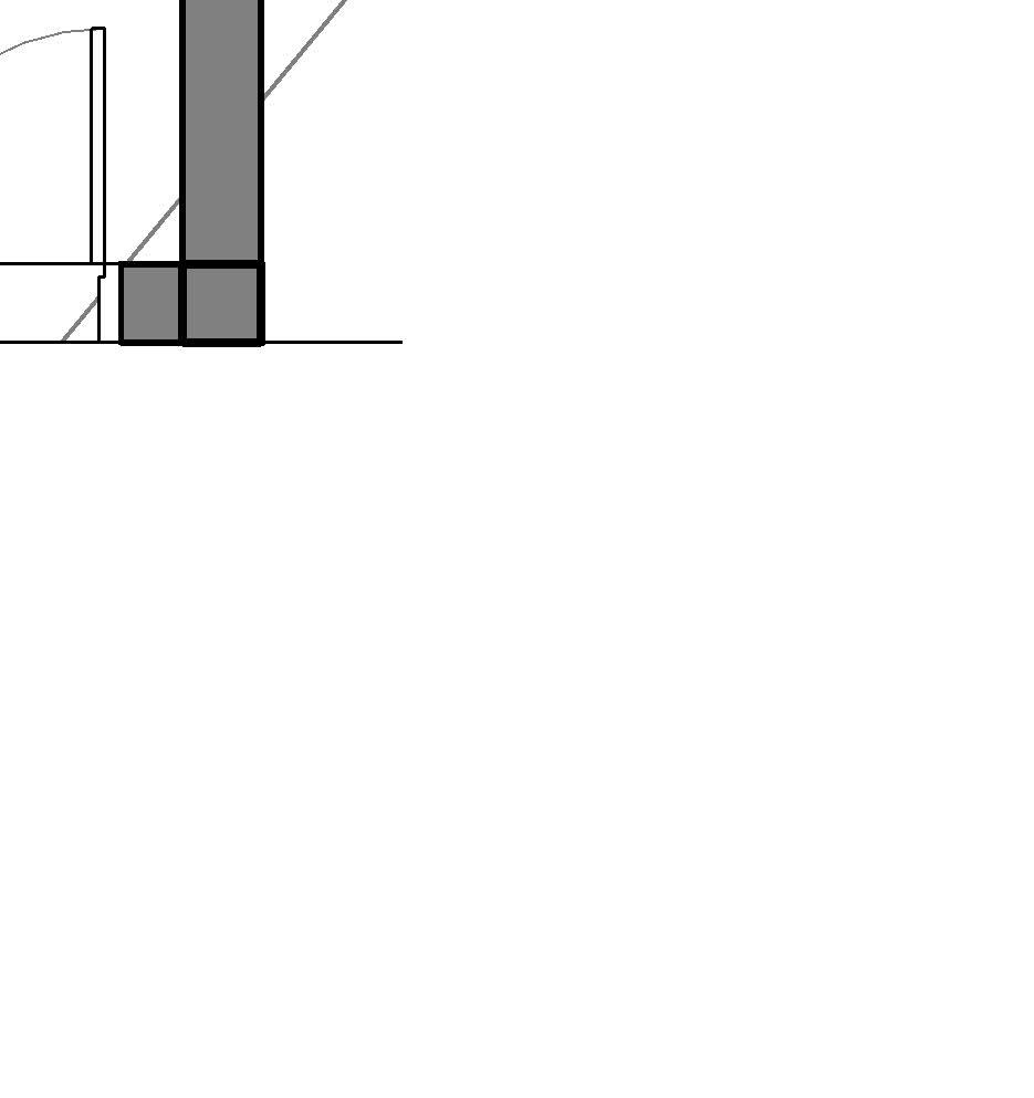
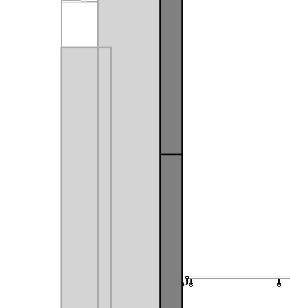
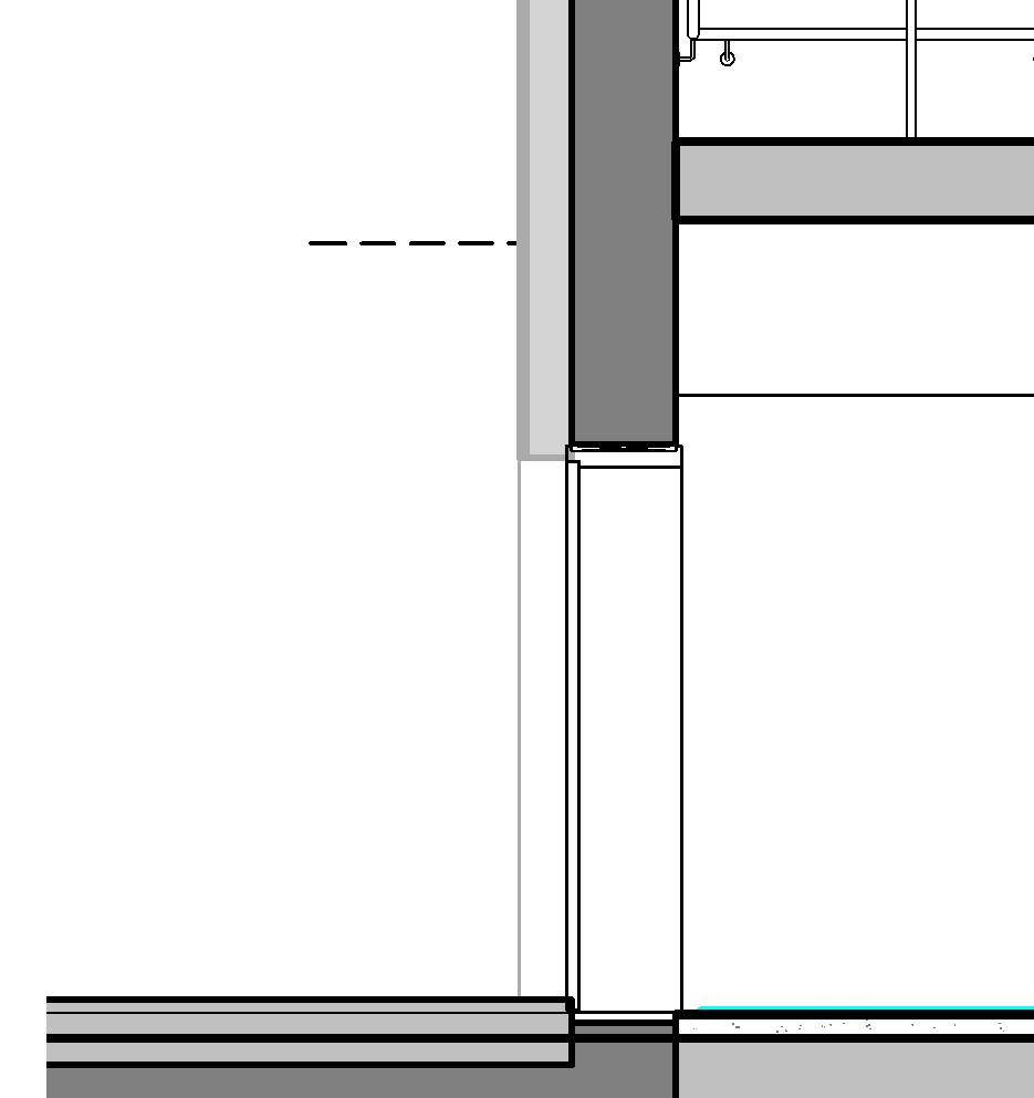
← Concrete Precast Stair interim landing, Section detail at 1:10
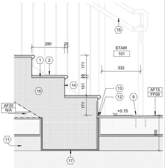
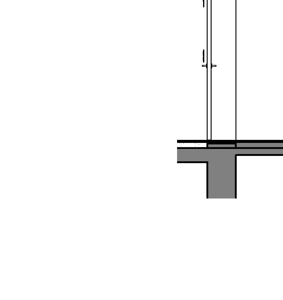
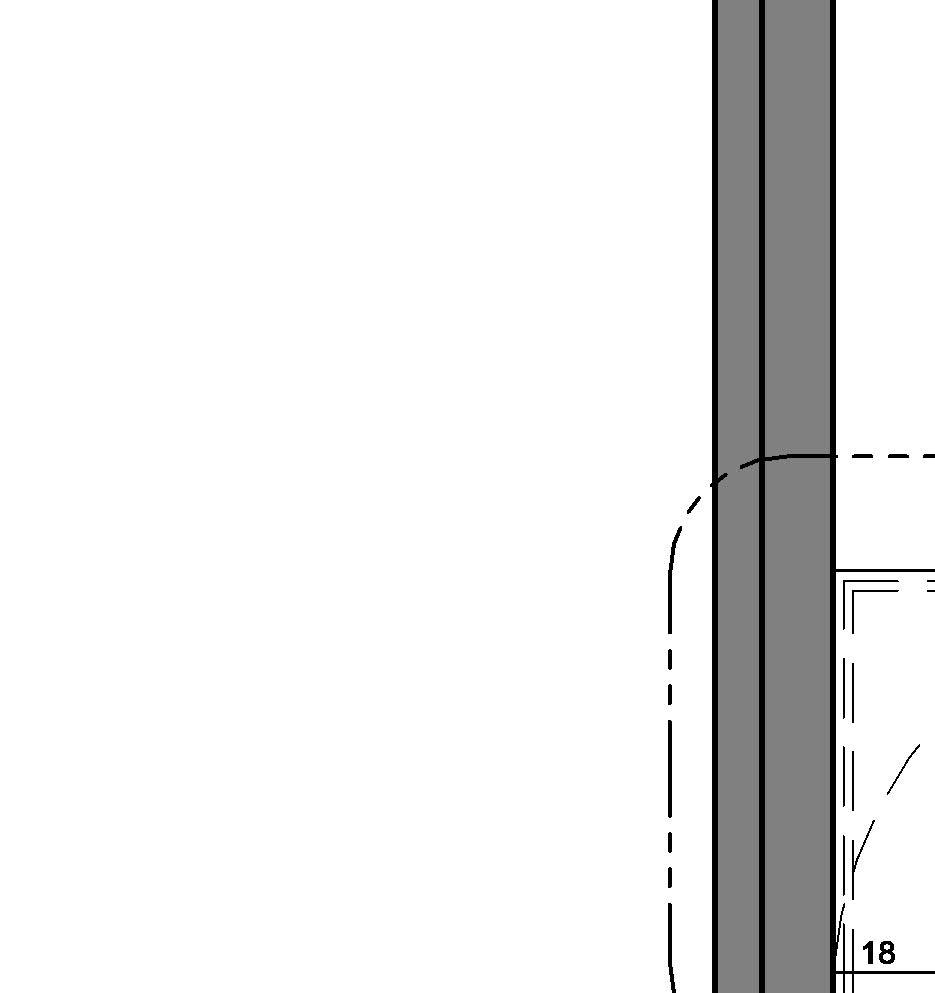
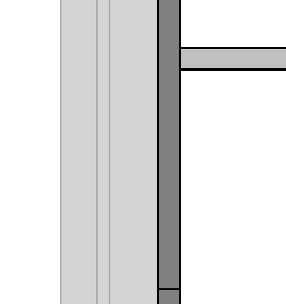
← Concrete Precast Stair bottom landing, Section detail at 1:10
1 SANDED CAST STONE TILE 300X300X
2 BEDDING LAYER / FLIESENKLEBER
3 SEPARATION
4 IMPACT INSULATION
5 STAIR MID LANDING. SANDED CAST STONE TILE 300X300X
6 NON COMBUSTIBLE ACOUSTICAL DECOUPLING
7 REINFORCED CONCRETE MID-LANDING
8 STAIR FLIGHTS. SANDED CAST STONE TILE 310X720X 30MM. TREADS ONLY
9 ELASTIC JOINT
10 CEMENT SCREED
11 IMPACT INSULATION EPS
12 REINFORCED CONCRETE SLAB.
13 EXPANDED POLYSTERENE INSULATION
37 STAIR FLIGHTS SANDED CAST STONE TILE 135X720X 30MM. RISERS ONLY
which stair works best for my needs?
Assembled
Most tipically used for metallic stairs, although it can also be made of wood
Widely used in industrial facilities and roof and mechanical accesses
Fast on-site installation
Modular and flexible
Lightweight components
Minimal wet works required
Lower labor intensity
Adaptable to complex geometries
Cast-in-place
Fabricated in-situ in concrete
Integrated into the building structure
High structural integrity and fire resistance
In DoD this type of stair is not commonly used
Prefabricated concrete
Factory-cast in concrete and delivered to site as complete flights or modular units
High Fire resistance
Fast to install
Most common type of stair in DoD. Used in all buildings typologies
Prefabricated Steel
Preassembled Steel stair unit fabricated offsite
Commonly used in industrial buildings and secondary accesses of residential buildings
Integrated with the structure
High fire resistance
Good acoustic insulation
Durable and solid
Fully customizable geometry
Ideal for monolithic design
Excellent durability
High fire resistance
Factory-controlled quality
Fast installation
Smooth finishes and uniform appearance
Reduced on-site labor
Lightweight compared to concrete
Very fast installation
Ideal for prefabricated or industrial buildings
Allows complex geometries with minimal
structural depth
Easily integrated with steel structures.
Very good for exteriors as it minimizes hazards
Lower fire resistance (depending on material)
Acoustic and vibration transmission
May require additional finishes for durability
Limited to smaller span applications
Tolerance issues if not properly coordinated
Requires formwork and curing time
Slower execution on-site
Weather-dependent
Higher labor and supervision costs
Changes are difficult once poured
Heavy weight requires cranes
Transportation limitations
Site access and lifting constraints
Limited flexibility after production
Requires precise dimensional coordination
Lower fire resistance (unless protected)
Requires surface treatment for corrosion resistance
May transmit noise and vibration
Expansion and deflection considerations
Often requires additional finishing for aesthetics
Railings in stair construction refer to the safety and support systems installed along the edges of stairways, landings, and ramps. They are designed to prevent falls, provide hand support, and define boundaries on vertical circulation paths. Railings generally fall into two categories:
Handrails: Graspable rails for guidance and support
Guards / Guardrails: Barriers to prevent falls from elevated surfaces
Purpose
• Provide safe grasp for people ascending/descending stairs
• Prevent falls from height at stair edges and landings
• Guide movement, especially for children, elderly, and individuals with disabilities
Placement
• Must be located on at least one side of stairways (residential)
• In public/commercial buildings, typically required on both sides
• Continuous across full run and landings
• Return to wall or floor to prevent clothing snags
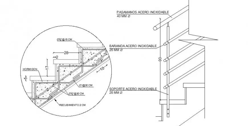
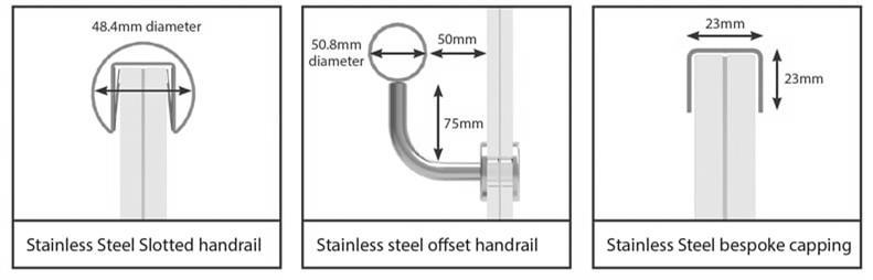
Materiality
• Typically, high end finishes, such as stainless steel, are reserved for interior railings
• Exterior railings tend to be finished with a more heavy-duty material, such as powder coat over galvanized steel
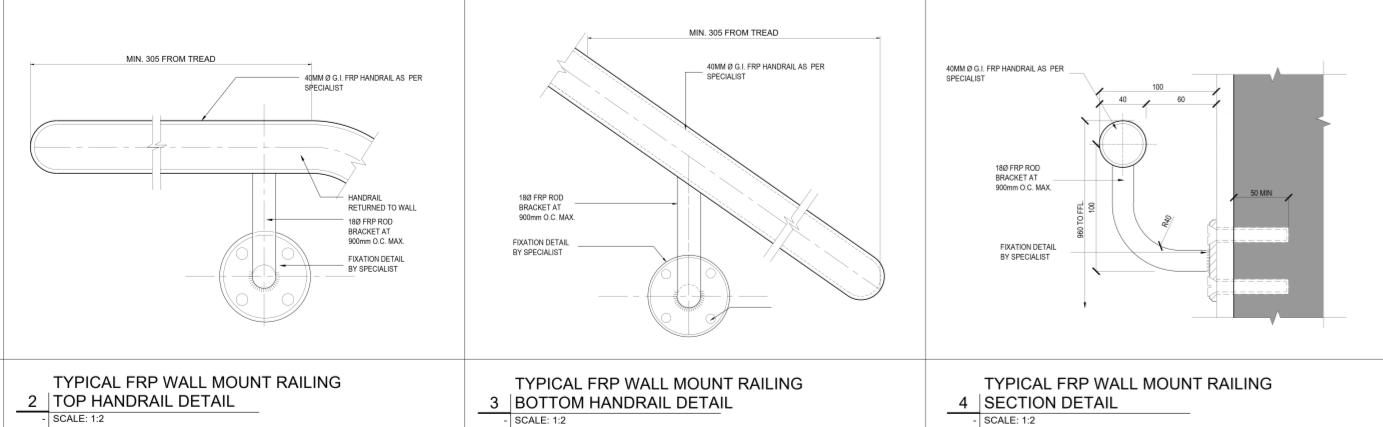
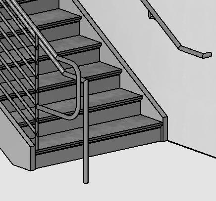
1. Wall-Mounted Handrails
• Installed directly to walls or structural supports
• Common in narrow stairwells or interior spaces
2. Guardrail Systems with Handrails
• Integrated top rail and infill system (vertical or horizontal members). Used on open stairs, balconies, or mezzanines.
These are two distinct elements:
•A guardrail: A structural barrier that prevents falls (typically 1,065 mm or 42 in high).
•A separate handrail: A lower, graspable rail (865–965 mm or 34–38 in above stair nosings), attached to or mounted inside the guard system.
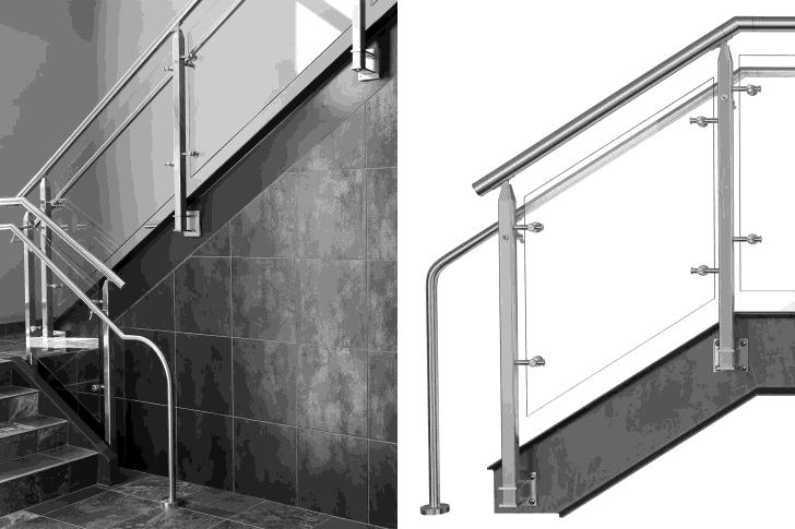
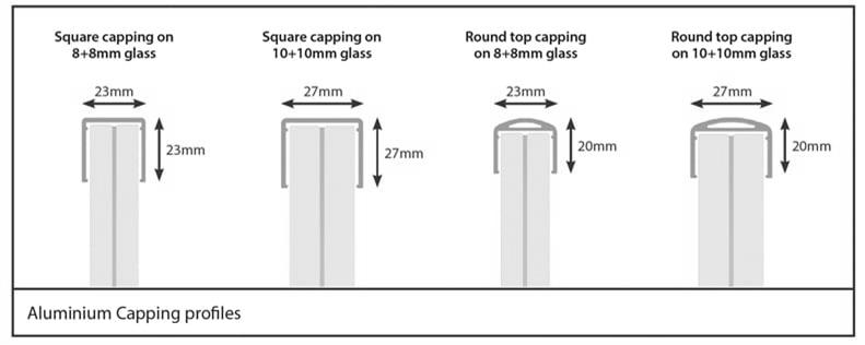
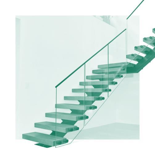
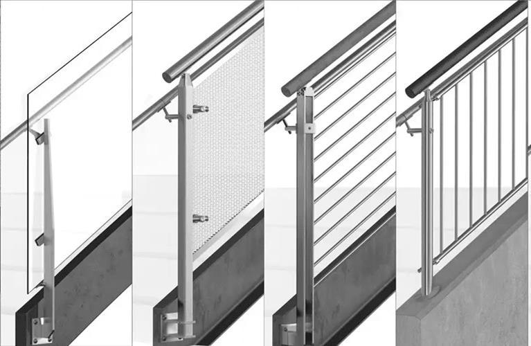
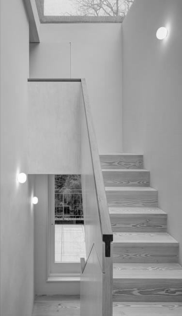
3. Glass or Panel Railings
• Tempered glass or polycarbonate panels in metal frames
• Modern aesthetics; must comply with impact and load ratings
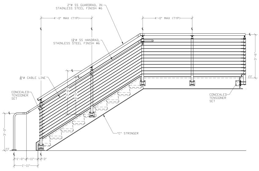
4. Cable or Rod Railings
•Tensioned horizontal elements (requires code interpretation)
•Often used outdoors or in custom designs; must avoid climbable pattern
5. Combination Systems
• Guard + handrail combined into a single assembly
• Often found in commercial or public access stairs
A handrail is a continuous graspable rail that provides support and stability to users ascending or descending a stair or ramp. It is distinct from guardrails and must meet specific height, shape, clearance, and extension requirements to comply with safety and accessibility regulations.
Parameter IBC / ADA Requirement
Height above nosing 865 mm – 965 mm (34 – 38 in)
Clearance from wall ≥ 38 mm (1.5 in)
Handrail diameter
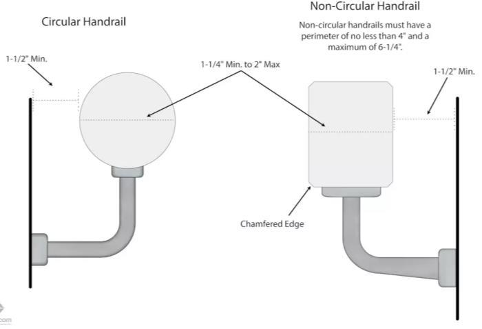
32 – 51 mm (1.25 – 2 in) for circular handrails
Non-circular perimeter ≤ 100 mm (4 in), max 57 mm (2.25 in) cross-section width
Continuity
Distance between rails (dual rails)
Continuous along full flight and across intermediate landings
≥ 38 mm (1.5 in) spacing to avoid entrapment
*Tolerances: Code allows up to ±13 mm (0.5 in) variation in height due to finish or mounting conditions.
•Handrails must be continuous and uninterrupted except at doorways
•No sharp or abrasive elements
•Ends must be returned to a wall, floor, or post
•Must support a load of 890 N (200 lb) in any direction
* Design Tips: avoid "boxy" profiles that can't be firmly grasped — stick to Type I for most public use; use returns or end caps to prevent snags or injuries; always doublecheck local amendments, especially in jurisdictions with stricter accessibility enforcement
Type I Handrail (Commercial & Residential)
•Circular: Ø 32–51 mm (1.25–2 in)
• Non-circular: Graspable with perimeter ≤ 100 mm
• Must have rounded edges and uniform profile
• Used in IBC, NFPA 101, and ADAcompliant facilities
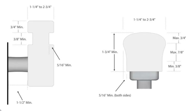
Type II Handrail (Residential Only)
• Larger cross-section (> 100 mm perimeter) allowed
• Must include graspable finger recesses on both sides
• Permitted only in Group R-2 and R-3 occupancies under IBC
• Typical in wood residential rails
A Handrail extension extension is the horizontal or sloped projection of a handrail beyond the stair flight or ramp run, designed to provide continuity of support for users as they begin or complete their movement. Extensions may be horizontal or aligned with the slope, depending on the location and applicable regulations.
Location Required Extension according to IBC and NFPA 101
Top of stairs
Bottom of stairs
Landing turns
Extend 305 mm (12 in) horizontally beyond top riser, parallel to floor
Continue slope of stair for depth of one tread, then optionally return to wall
Handrail must be continuous at inside corners and across landings
Extensions must return to wall, guard, or post to avoid catching clothing or bags.
*Exceptions - Handrails not required to extend on: within dwelling units; Group R-3 occupancies (detached oneand two-family dwellings); alterations to existing stairs where full compliance is impractical
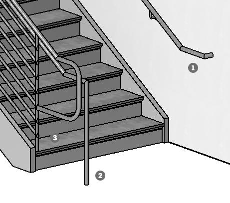
1. Straight Horizontal Extension
• Flat extension continuing in the direction of travel at the top of stairs or ramps
• Required by ADA and IBC
• Most common type for both stairs and ramps
2. Sloped Extension
• Extends along the slope of the stair flight
• Typically used at the bottom of stair runs
• Continues for the horizontal distance of one tread
3. Return-to-Wall Extension
• Handrail curves or bends back to meet the adjacent wall or post
• Minimizes clothing/snags
• Often required in commercial and public applications
4. Return-to-Floor (Downturn)
• Extension bends downward to terminate at or near the floor surface
• Common in freestanding handrail systems or guardrail-integrated designs
5. Wrap-Around (Corner) Extension
• Used at landings or turns, where the handrail must continue around corners
• Must remain continuous and graspable
IBC Definition (Section 202):
“A guard is a building component or a system of components located at or near the open sides of elevated walking surfaces that minimizes the possibility of a fall”
A guardrail is a structural barrier placed along open sides of elevated walking surfaces—such as stair landings, ramps, balconies, or floor openings—to prevent falls from height. Unlike handrails, guardrails are not graspable elements for support; they are fall protection components.
Specification Standard Requirement - IBC 2021 (Section 1015) & NFPA 101 (Section 7.2.2.4)
Minimum height 1,065 mm (42 in) above walking surface or landing
Exceptions 915 mm (36 in) allowed for R-3 occupancies (e.g. single-family homes)
Openings (Sphere Rule) Must prevent passage of a 100 mm (4 in) sphere through any opening
Triangular openings Below guardrail on stairs, no opening larger than a 152 mm (6 in) triangle
Load capacity Withstand 0.89 kN/m (50 lb/ft) horizontally or 200 lb point load
Tolerances ±13 mm (½ in) in height variation typically accepted due to finish or mounting
All measurements are taken vertically from the leading edge of the stair nosing or floor surface to the top of the guard.
• Location Requirements: Required at any walking surface elevated more than 760 mm above the floor/grade. Includes stairs, ramps, landings, mezzanines, balconies, and retaining walls adjacent to walking areas.
• ADA does not directly require guardrails unless part of a barrier-free route, in which case protrusion limits and edge protection apply (e.g., ramps with drop-offs)
• Glass Guards: must be safety glazing (laminated or tempered); must not shatter under point load; top rail still required over glass in some jurisdictions unless laminated glass is designed to carry full guard load
Common Guardrail Types
1. Solid Panel Guardrail
• Material: Glass, acrylic, concrete, or metal panel
• Appearance: No open balusters or infill
• Benefits: High safety, clean design, can act as wind barriers
• Code Note: Glass guards must be laminated or tempered safety glass (IBC §2407)
2. Picket or Vertical Bar Guardrail
• Material: Steel, aluminum, wrought iron, or wood
• Spacing: Pickets ≤ 100 mm (4 in) apart
• Benefits: Traditional appearance, ventilation
3. Cable Rail Guards
• Material: Stainless steel cables tensioned between posts
• Spacing: Cables ≤ 100 mm (4 in) apart with deflection under load considered
• Consideration: Requires precise tensioning to comply with the sphere rule
4. Mesh or Screen Guards
• Material: Metal wire mesh or perforated panels
• Benefits: Industrial or modern aesthetics, safety through redundancy
• Note: Mesh aperture must not allow 100 mm sphere to pass through
5. Integrated Wall Guardrail
• Guard formed by architectural walls or parapets ≥ 1,065 mm tall
• Common in commercial or exterior balconies
The placement of posts, balusters, and railings on stairs and landings is carefully regulated to prevent falls, climbing hazards, and entrapment, especially for children. Multiple building codes and standards (IBC, IRC, NFPA, and others) include specific spacing rules, rejection spheres, and shape-based safety tests:
Standard Rule Purpose
IBC (2021) Openings must reject a 100 mm (4 in) sphere Prevent head entrapment (especially children)
IRC (2021) 100 mm sphere
Applies to all guardrails and balusters
NFPA 101 Same: ≤ 100 mm (4 in) For means of egress and fall protection
*Applies to balusters (vertical members), Openings below the handrail on guards, any portion of the guard assembly up to 900 mm (36 in) above the walking surface
Triangle Opening Rule (Stair Side)
According to all major codes The triangular opening formed by the riser, tread, and bottom rail must not allow passage of a 152 mm (6 in) sphere. This prevents entrapment or head wedging under the stair guard.
Placement
Condition
Typical Code Requirement
Guardrail terminal post spacing No specific spacing, but must resist load
Guardrail intermediate support spacing Often ≤ 1,800 mm (6 ft) depending on material
Handrail post support (on stairs) Must support 200 lb concentrated load (IBC)
Top rails and infill supports Must resist 50 lb/ft uniform load (IBC Section 1607.8)
*Structural design (not just spacing) is key. Most codes refer to ASCE 7 or NBC standards for loading
Design Tips for Compliance
• Use vertical balusters instead of horizontal to deter climbing
• Keep baluster spacing consistent — don't taper on open stairs
• Watch bottom of guardrails on stairs: that’s where the triangle rule bites
• Test with 100 mm & 152 mm spheres in your BIM/revit model if possible
↑ Steel railing with balusters placed at 100mm

Common Hazards These Rules Prevent
• Children squeezing through balusters (100 mm sphere rule)
• Head/neck entrapment under guards (152 mm triangle rule)
• Climbing opportunities due to horizontal rails or wide spacing
• Inadequate structural support leading to failure under load

10 GLAZED CANOPY WITH METAL SUBSTRUCTURE OVER ENTRANCE
GLASVORDACH

1.
3.
4.
5.
UND FENSTERLISTE
6. SIEHE ZEICHNUNGEN VON A-621 BIS A-627 FUER DIE LISTE DER INNENAUSFUEHRUNGEN
7. SIEHE ZEICHNUNGEN A-628 BIS A-630 FUER WANDTYPEN
8. SIEHE ZEICHNUNG A-631 FUER INFORMATIONEN ZU DEN BODENTYPEN
9. EINBAUTEN VOM GU GELIEFERT UND INSTALLIERT IN SCHWARZ MIT ROTER SCHRAFFUR. EINBAUTEN BAUSEITS GELIEFERT UND INSTALLIERT IN GRAU. SIEHE MOEBELPLANSZEICHNUNGEN A-633 UND A-634.
10. FUER ROHBAU-UND OEFFNUNGSMASSE DER TRAGENDEN ELEMENTE, SIEHE STATIKZEICHNUNGEN.
11. INFORMATIONEN ZU TRAGWERK, SPRINKLER, BRANDSCHUTZ, LUEFTUNGS, SANITAER UND ELEKTROPLANUNG SIND DEN JEWEILIGEN PLANUNGSPAKETEN ZU ENTNEHMEN
12. ALLE PUNKTUELLEN HOEHEN UND EBENEN BEZIEHEN SICH AUF DIE HOEHE DES PROJEKTS VON 0,00 M. SIEHE ALLGEMEINE HINWEISE ZEICHNUNGEN G-010 UND G-011 FUER DIE ENTSPRECHENDE HOEHE UEBER DEM NULLPUNKT
13. DIE HANDLAEUFE UND GELAENDER IN DIESER EINRICHTUNG ENTSPRECHEN VOLLSTAENDIG DEN STANDARDS DES INTERNATIONAL BUILDING CODE (IBC 1011.11 UND 1014) UND DER DEUTSCHEN INDUSTRIENORM (DIN 18065), WAS SICHERHEIT UND EINHALTUNG DER REGULATORISCHEN ANFORDERUNGEN GEWAEHRLEISTET.
14. FUER DIE AN DER DECKE MONTIERTE ELEMENTE UND POSITIONIERUNG, SIEHE DER DECKENSPIEGELPLAENE
11 PREFABRICATED CONCRETE STAIR INCLUDING LANDINGS FERTIGTEILBETONTREPPE INKL. PODESTEN
12 PAINTED STEEL CANOPY STAHLVORDACH GESTRICHEN
13 SNOW GUARD SCHNEEFANGGITTER
14 SYNTHETIC SLATE SHINGLES KUENSTLICHE SCHINDELN AUS
SCHIEFER (FASERZEMENT)
15 REINFORCED CONCRETE MID-LANDING MITTELPODEST AUS STAHLBETON
16 REINFORCED CONCRETE SLAB. REFER TO STRUCTURAL PACKAGE FOR DIMENSIONS STAHLBETONDECKE. SIEHE TRAGWERKPAKET FUER ABMESSUNGEN
17 MANUAL SMOKE EXHAUST AND VENTILATION CALL BUTTON MANUELLE RAUCHABZUGS UND BELUEFTUNGSTASTE (RWA TASTE)
18 STAIR FLIGHTS. SANDED CAST STONE TILE 310X720X 30MM. TREADS ONLY TREPPENFLÜEGE. GESCHLIFFENE KUNSTSTEINFLIESE 310X720X30 MM. NUR STUFEN
19 STAIR FLIGHTS. SANDED CAST STONE TILE 135X720X 30MM. RISERS ONLY TREPPENFLÜEGE. GESCHLIFFENE
KUNSTSTEINFLIESE 135X720X30 MM. NUR STG.
20 INACCESSIBLE SPACE UNDER STAIRCASES NICHT BEGEHBARER HOHLRAUM UNTER TREPPENHAEUSERN
21 FINAL SHAPE AND VOLUME OF EXCAVATION AND EXCHANGE PAD AS PER CONTRACTOR ENDGUELTIGE FORM UND VOLUMEN DES AUSHUBS UND DER AUSTAUSCHPLATTE GEMAESS DEN
SPEZIFIKATIONEN DES BAUUNTERNEHMERS
22 EXCHANGE PAD, FINAL BORDERS AND VOLUME TO BE DETERMINED BY CONTRACTOR BASED ON CALCULATIONS. REFER TO GEOTECH REPORT GRUENDUNG. ENDGUELTIGE RAND- UND VOLUMENANGABEN SIND VOM BAUUNTERNEHMER AUF DER BASIS VON BERECHNUNGEN ZU BESTIMMEN. VERWEIST AUF
GEOTECHNISHCER UNTERLAGEN
23 DRAINAGE GUTTER FOR EXTERNAL DOORS / RINNE, ENTWASSERUNGS RINNE FUER TUEREN
24 EXTERNAL PLATFORM DONE WITH PAVERS AND PRECAST STEPS. REFER TO CIVIL PACKAGE AUSSENPODEST GEBAUT AUS
PFLASTERSTEINEN UND VORGEFERTIGTEN BETONSTUFEN. SIEHE
6.
4.
CF04 PAINTED EXPOSED STRUCTURE SICHTBAR ANGESTRICHENE OBERFLAECHE PAINTED GYPSUM BOARD GESTRICHENE GIPSKARTONPLATTE
WF03 INTERIOR WHITE PAINT INNEN WEISS ANSTRICHEN
F01 SANDED CAST STONE TILE300 X 300 X 20MM GESCHLIFFENE KUNSTSTEINFLIESE 300 X 300 X 20 MM 10 REINFORCED CONCRETE, REFER TO STRUCTURAL DRAWINGS STAHLBETON, SIEHE TRAGWERKSPLAENE
BF03 SKIRTING TILE SANDED CAST STONE TILE - 70 MM HEIGHT SOCKELFLIESE GESCHLIFFENE KUNSTSTEINFLIESE -70 MM HOEHE
5.
6.
DER INNENAUSFUEHRUNGEN
7. SIEHE ZEICHNUNGEN A-628 BIS A-630 FUER WANDTYPEN
8. SIEHE ZEICHNUNG A-631 FUER INFORMATIONEN ZU DEN BODENTYPEN
9. EINBAUTEN VOM GU GELIEFERT UND INSTALLIERT IN SCHWARZ MIT ROTER SCHRAFFUR. EINBAUTEN BAUSEITS GELIEFERT UND INSTALLIERT IN GRAU. SIEHE MOEBELPLANSZEICHNUNGEN A-633 UND A-634.
10. FUER ROHBAU-UND OEFFNUNGSABMESSUNGEN DER TRAGENDEN ELEMENTE SIEHE DURCHBRUCHSZEICHNUNGEN A-811 BIS A-853 UND ZEICHNUNGEN DER TRAGWERKSPLANUNG
11. INFORMATIONEN ZU TRAGWERK, SPRINKLER, BRANDSCHUTZ, LUEFTUNGS, SANITAER UND ELEKTROPLANUNG SIND DEN JEWEILIGEN PLANUNGSPAKETEN ZU ENTNEHMEN
12. ALLE PUNKTUELLEN HOEHEN UND EBENEN BEZIEHEN SICH AUF DIE HOEHE DES PROJEKTS VON 0,00 M. SIEHE ALLGEMEINE HINWEISE ZEICHNUNGEN G-010 UND G-011 FUER DIE ENTSPRECHENDE HOEHE UEBER DEM NULLPUNKT
13. DIESE ZEICHNUNG ZEIGT TREPPENHAUS 3 UND IST SYMMETRISCH ZUM TREPPENHAUS 1
14. DIE HANDLAEUFE UND GELAENDER IN
WAS SICHERHEIT UND EINHALTUNG DER REGULATORISCHEN ANFORDERUNGEN GEWAEHRLEISTET.
15. FUER DIE AN DER DECKE MONTIERTE ELEMENTE UND POSITIONIERUNG, SIEHE DER DECKENSPIEGELPLAENE
AUSSENPLANUNG PAKET DoD specific
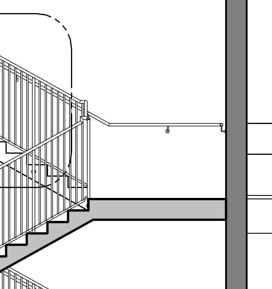
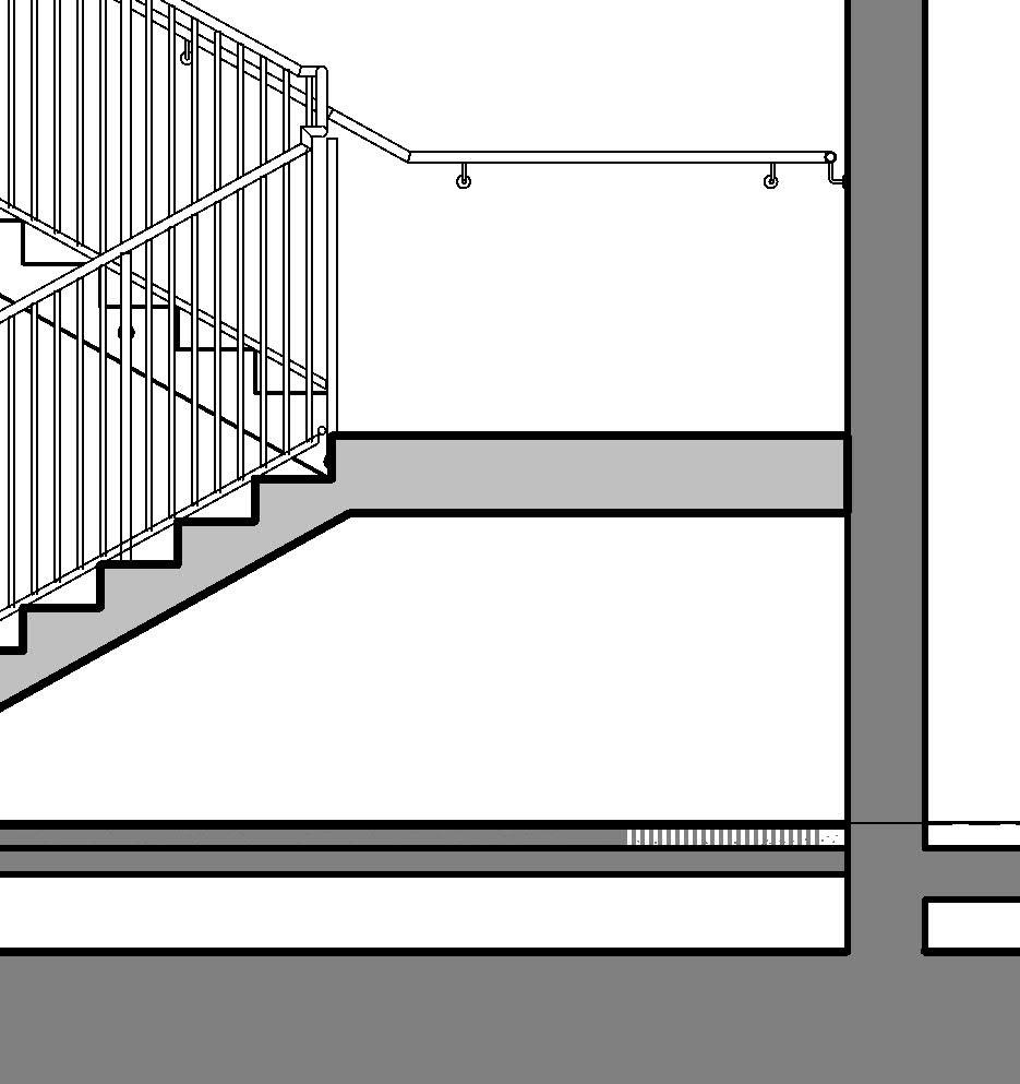
A1 CROSS SECTION -NW SIDE STAIRCORE (SE STAIRCORE MIRRORED) QUERSCHNITT -NW-SEITIGES TREPPENHAUS (SE-SEITIGES TREPPENHAUS GESPIEGELT)
LONG. SECTION -NW SIDE STAIRCORE (SE STAIRCORE MIRRORED) LANG. SCHNITT -NW SEITE TREPPENHAUS (SE TREPPENHAUS GESPIEGELT) A4
GRAPHIC SCALE MASSSTABSBALKEN
TYP. CONNECTION TO STEEL STRINGER LEITDETAILSTAHLTRAEGER ANSCHLUSS
SCHAAL: MASSSTAB: SCALE 1 5
6.
ZU ENTNEHMEN
7. ALLE PUNKTUELLEN HOEHEN UND EBENEN BEZIEHEN SICH AUF DIE HOEHE DES PROJEKTS VON 0,00 M. SIEHE ALLGEMEINE
8.
9.
10.
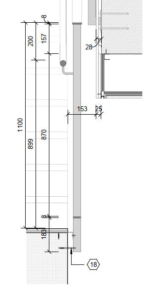
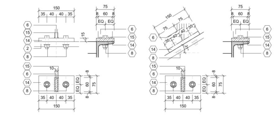
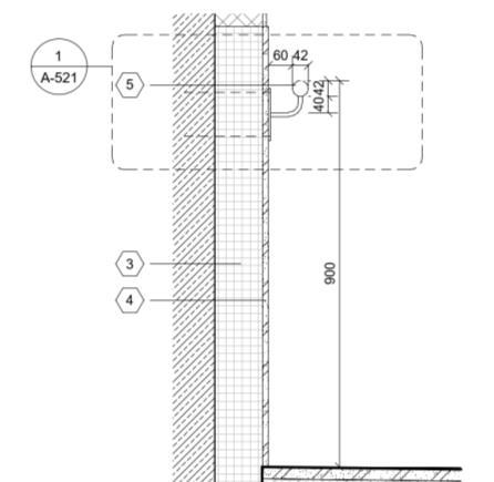
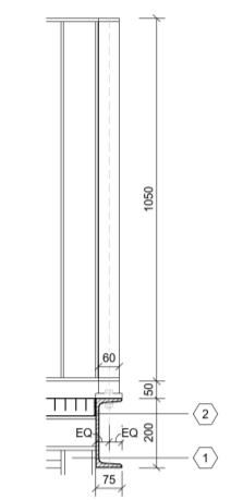
FAÇADE HANDRAIL ANCHOR TYP. HANDLAUF-FASSADENANKER
8. FUER DIE NIVEAUSPEZIFISCHEN PUNKTHOEHEN SIEHE AUSSENPLANUNG PAKET UND ZEICHNUNGEN
9. FUER DIE NEIGUNGSWINKEL DER VERANKERUNGSPLATTEN DER GELAENDERPFOSTEN SIEHE NEIGUNGSMESSUNGEN AUS AUSSENPLANUNG PAKET UND ZEICHNUNGEN
10. ALLE TUERZARGEN UND -FLUEGEL GEMAESS DEN LOESUNGEN DES HERSTELLERS ZU ENTWICKELN WEREDEN
ROOF ACCESS LADDER TOP -PLAN DACHDURCHSTIEGSLEITER OBERER BEREICH -PLAN


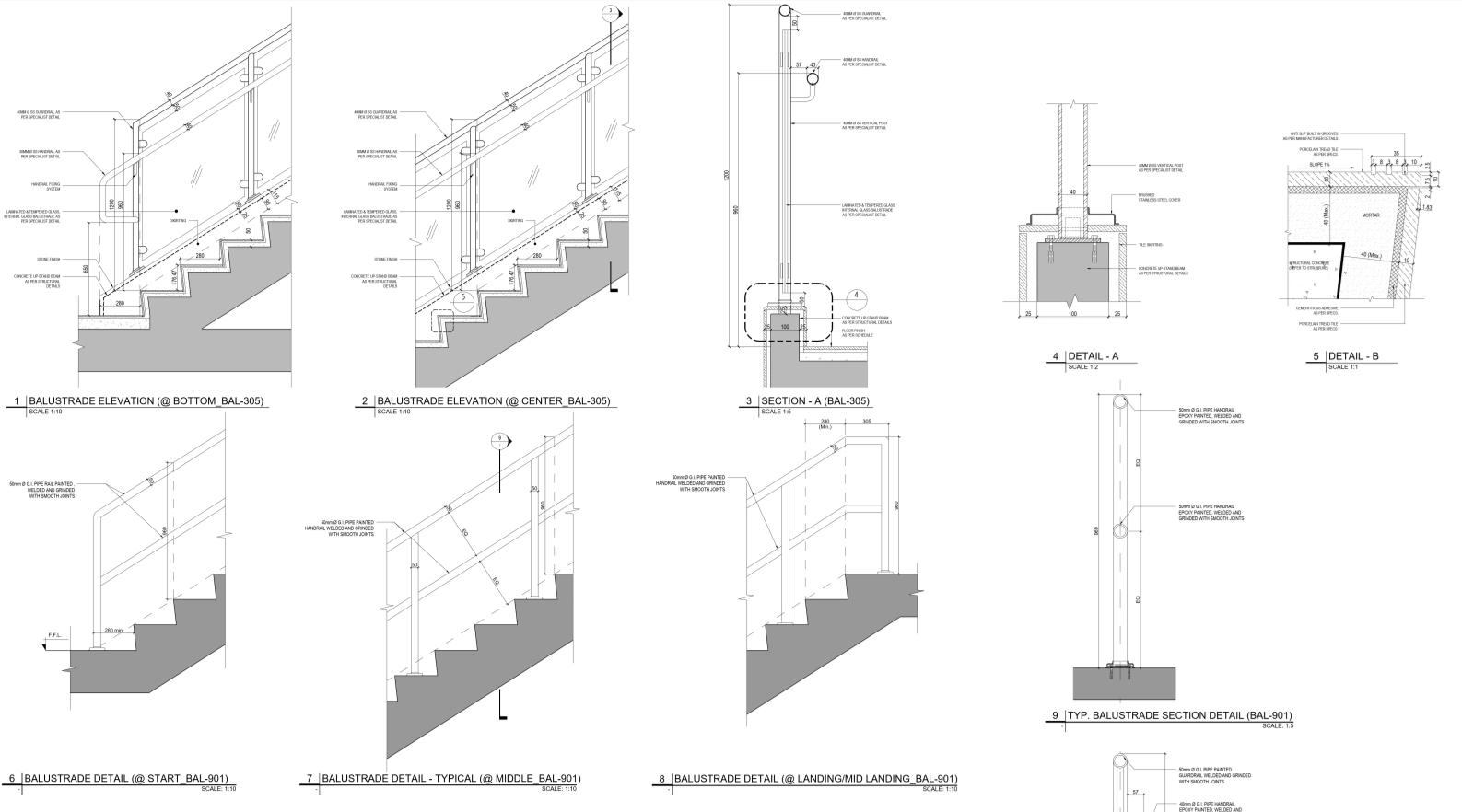
TYPICALSTAIRRAILINGSECTION
TYPICALSTAIRRAILING 2 -SCALE:1:10
SECTIONDETAIL-2(@MIDFLIGHT_BAL-901)
40MMØG.IPIPE GUARDRAIL,WELDED ANDGRINDEDWITH SMOOTHJOINTS (REFERTO SPECIFICATIONS)
40MMØG.IPIPEPOST, WELDEDANDGRINDED WITHSMOOTHJOINTS
20MMØG.IPIPE BALUSTRADE,WELDED ANDGRINDEDWITH SMOOTHJOINTS
30MMØG.I.PIPE BOTTOMRAIL,WELDED ANDGRINDEDWITH SMOOTHJOINTS
40MMØG.IPIPERAIL, HANDRAILWELDEDAND GRINDEDWITHSMOOTH JOINTS(REFERTO SPECIFICATIONS)
90Ø6MMTHK.DISC WELDEDTOBALUSTER TOFORMBASEPLATE 8 AR-540108
EXPANSIONBOLTS NOS.FIXEDTOBASE PLATE(ASPER SPECIALISTDETAIL)
EXPANSIONBOLTSNOS.
TYPICALSTAIRRAILING 5 -SCALE:1:10
SECTIONDETAIL-1(@FIRSTFLIGHT_BAL-901)
50mmØG.I.PIPEPAINTED GUARDRAILWELDEDANDGRINDED WITHSMOOTHJOINTS
40mmØGPIPEHANDRAIL EPOXYPAINTEDWELDEDAND GRINDEDWITHSMOOTHJOINTS
30mmØG.I.PIPEBOTTOMRAIL PAINTEDWELDEDANDGRINDED WITHSMOOTHJOINTS
REFERTOSTRUCTURALPACKAGE


HANDRAILWELDEDAND GRINDEDWITH SMOOTHJOINTS
20MMØG.IPIPE BALUSTRADE,WELDED ANDGRINDEDWITH SMOOTHJOINTS (REFERTO SPECIFICATIONS)
40MMØG.IPIPEPOST,
5 -SCALE:1:10
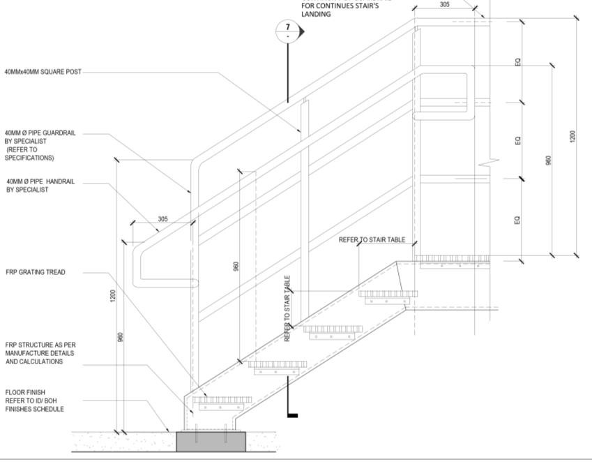
SECTIONDETAIL-1(TYPICALFLIGHTSECTION)
50mmØG.I.PIPEPAINTED GUARDRAILWELDEDAND GRINDEDWITHSMOOTHJOINTS
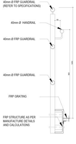
40mmØFRPGUARDRAIL (REFERTO SPECIFICATIONS)
40mmØFRPGUARDRAIL (REFERTOSPECIFICATIONS)
40mmØHANDRAIL
20ØG.I.PIPEBALUSTRADE PAINTED,WELDEDANDGRINDED WITHSMOOTHJOINTS
40mmØFRPGUARDRAIL
FRPSTRUCTUREASPER MANUFACTUREDETAILS ANDCALCULATIONS
FRPSTRUCTUREASPER MANUFACTUREDETAILS ANDCALCULATIONS
FRPSTAIRCASERAILING(AM-325)
7 -SCALE:1:10
SECTIONDETAIL-2(FRPRAILING)
40mmØFRPGUARDRAIL (REFERTO SPECIFICATIONS)
40mmØFRPGUARDRAIL
40mmØFRPGUARDRAIL
FRPGRATING FRPKICKPLATE (REFERTOSPECIFICATIONS)
FRPSTRUCTUREASPER MANUFACTUREDETAILS ANDCALCULATIONS
RAISEDFRPPLATFORMRAILING(AM-325)
8 -SCALE:1:10
SECTIONDETAIL-1
40mm FRPGUARDRAIL (REFERTOSPECIFICATIONS)
40mmØFRPGUARDRAIL
40mmØFRPGUARDRAIL
FIXATIONDETAILBY SPECIALIST
CONCRETEUPSTAND REFERTOSTRUCTURAL PACKAGE
RAISEDFRPPLATFORMRAILING
9 -SCALE:1:10
SECTIONDETAIL-2
40mmØFRPGUARDRAIL (REFERTOSPECIFICATIONS)
40mmØFRPGUARDRAIL
40mmØFRPGUARDRAIL
FIXATIONDETAILBYSPECIALIST
CONCRETEUPSTAND REFERTOSTRUCTURAL PACKAGE
FRPGARDRAILONUPSTAND
11 -SCALE:1:10
SECTIONDETAIL-2
REFERTOSTRUCTURALPACKAGE
30mmØG.I.PIPEBOTTOMRAIL PAINTEDWELDEDANDGRINDED WITHSMOOTHJOINTS
TYPICALMISCELLANEOUSCONCRETESTAIRCASEANDRAILING 6 -SCALE:1:10
TYPICALMISCELLANEOUSSTEELSTAIRCASEANDRAILING
SECTIONDETAIL-1(TYPICALFLIGHTSECTION)
FRPGARDRAILONUPSTAND 13 -SCALE:1:2 FRPHANDRAILRETURNDETAIL TYPICALPLAN (AM-325)
FRPGARDRAILONUPSTAND
10 -SCALE:1:10
SECTIONDETAIL-1
12 -SCALE:1:10
SECTIONDETAIL-2
40MMØG.IPIPERAIL,
40MMØG.IPIPEGUARDRAIL, WELDEDANDGRINDEDWITH


1
Key Stair Components Assessed
• Stair flights
• Landings
• Handrails and guardrails
• Tread and riser design
• Nosings and finishes
• Lighting and signage
• Fire-rated enclosures
• Railings
• Tactile ground surface indicators at stair approach zones
• Clear width of ≥915 mm between handrails
• No open risers; closed risers to ensure child safety
• No protrusions into stairway clearance (including door swings)
• Proper landings provided at all required intervals
• Durable, cleanable finishes for stair treads
• Signage indicating “Watch Your Step” at stair entries
• Adequate lighting levels maintained (min. 100 lux)