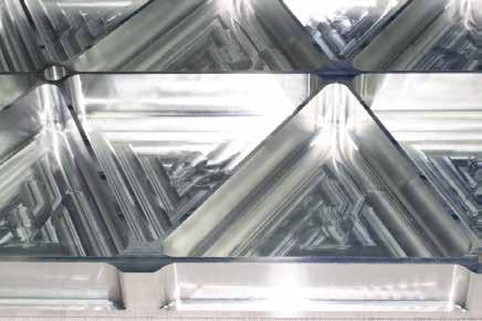
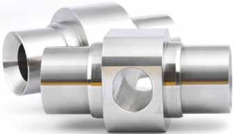
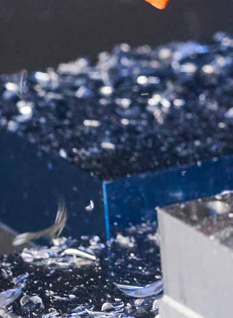
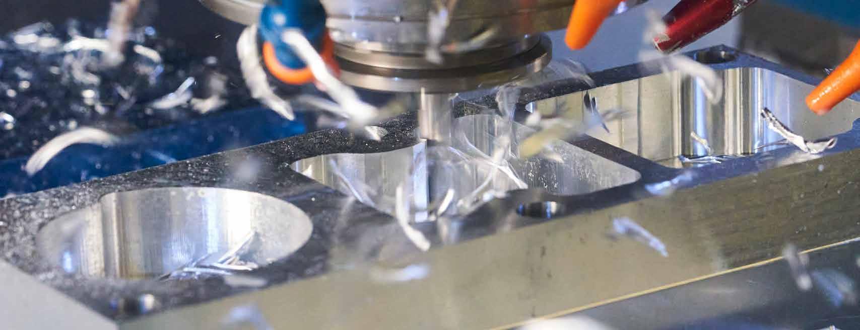
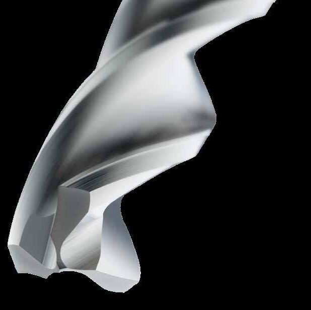
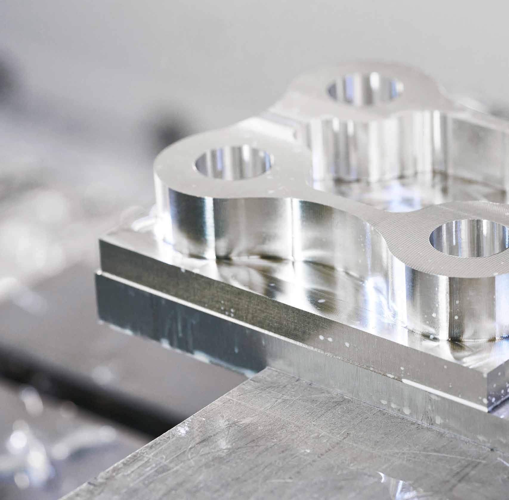
Aluminum Machining Solutions
High Performance Milling and Holemaking
HIGH
ALUMINUM MACHINING


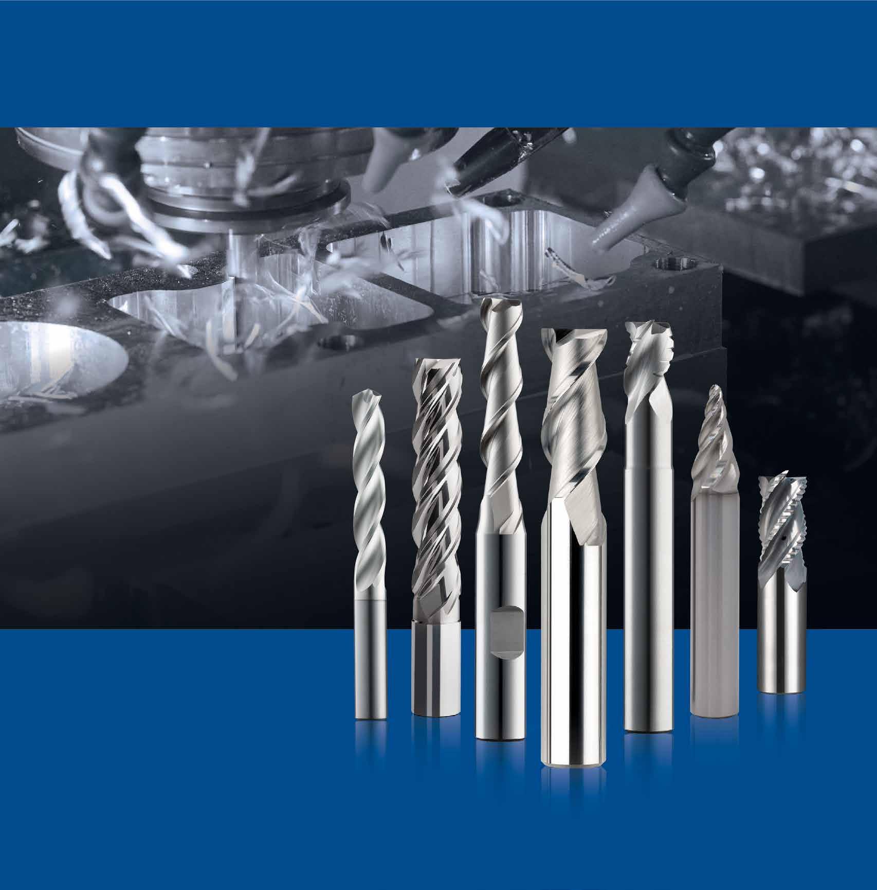
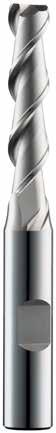
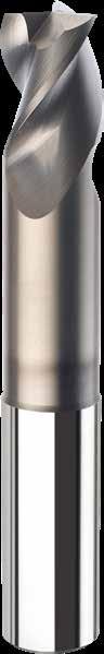
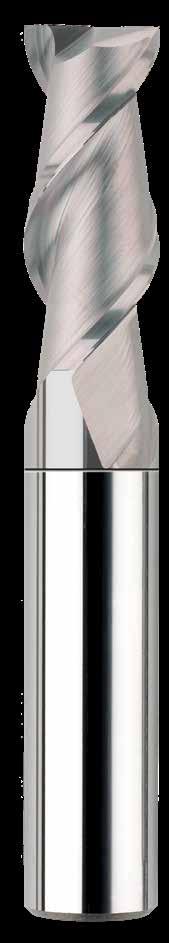
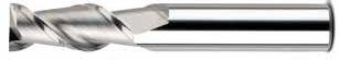
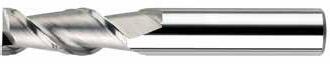
S-Carb - 2 and 3 Flute End Mills

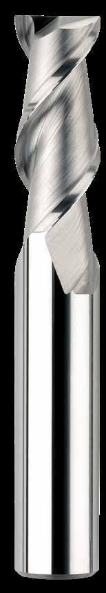
- 2 Flute End Mills
Hi-PerCarb 131N - 3 Flute Drills
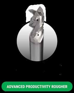
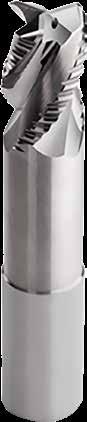
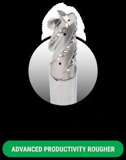
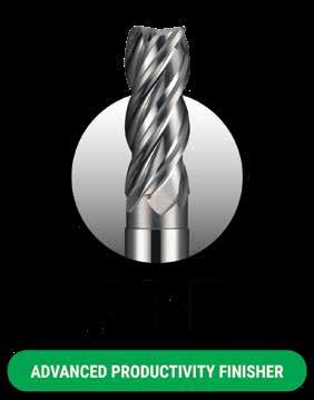
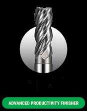
ADVANCED PRODUCTIVITY
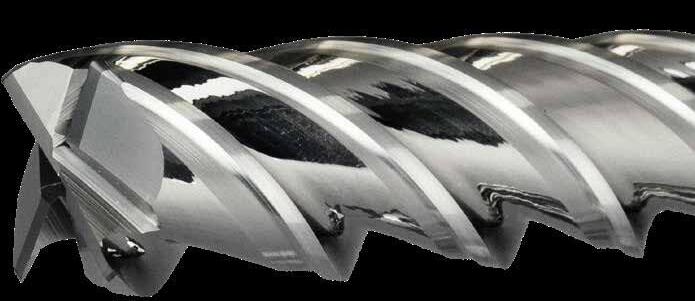
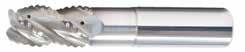
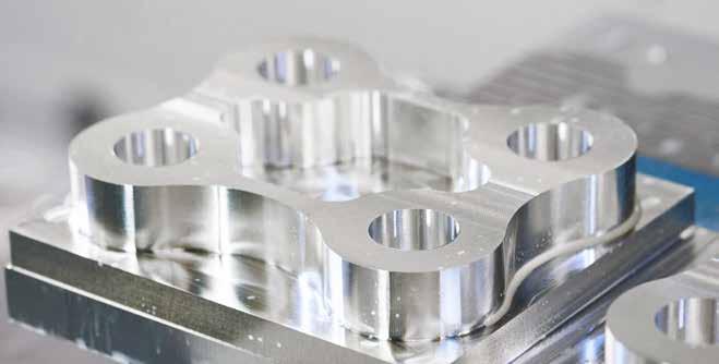
ALUMINUM MACHINING APR ROUGHING |
ROUGHING
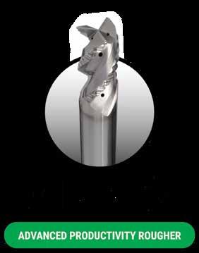
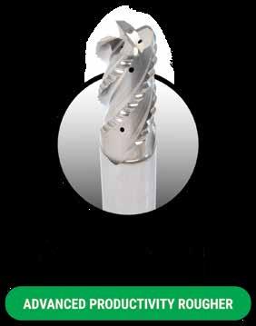
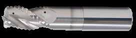
Engineered for peak performance, the Advanced Productivity Roughers redefine aluminum machining performance
• 3 and 4 flute variable pitch geometry for reduced vibration
• Re-engineered flute design for reduced load at high metal removal rates
• Improved design for coolant and MQL
• 4 flute variant for ultimate metal removal rates on high-powered machines
• Ti-NAMITE-B coated for extended tool life
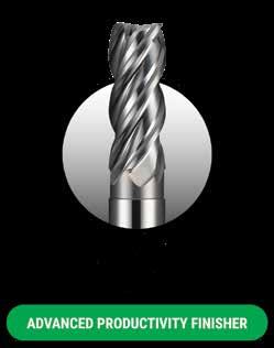
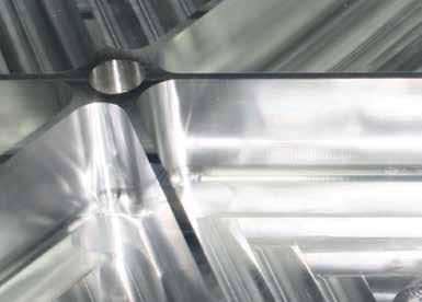
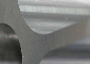
FINISHING
Developed and engineered for high-feed finishing of thin wall aluminum applications. Significant reduction in machining times, with straighter walls and superior finishes compared to waterlining.
• 4 flute unique variable geometry reduces vibration for single-pass thin wall finishing
• Through coolant design
• Polished flutes for superior finishes
• Significant reduction in cycle times
TYPICAL METHOD
High-speed waterline nishing, multiple passes at numerous levels to produce acceptable thin walls


APF METHOD

High-speed nishing at full depth without wall distortion ONE HIT
Dramatic increase in productivity versus the high speed waterline finishing method, which requires multiple passes to produce acceptable thin walls.
T i -NAMITE-B COATING TECHNOLOGY
Available with TiB2 Coating (Titanium Diboride). This ceramic based coating ensures a smooth surface and a low affinity to cold welding or edge build-up, which makes it optimal for aluminum and copper applications. It has high toughness and high hardness.
• Hardness: 4000 HV
• Oxidation Temperature: 850°C / 1562°F
• Coefficient of Friction: 0.10 – 0.20
• Thickness: 1 – 2 Microns (based on tool diameter)

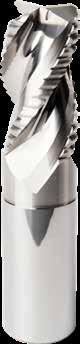
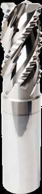
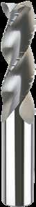
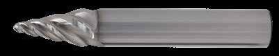
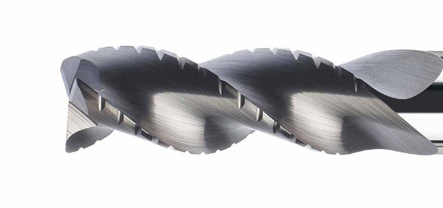
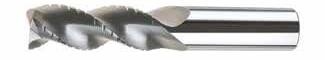
S-Carb APR
3 Flute Advanced Productivity Rougher
43APR-3
• Ultra high-productivity rougher for Aluminum alloys, specifically for aircraft components
• Designed for high material removal rates (MRR)
• 3 flute variable geometry with side exit coolant holes
• Open fluting for deep slotting and profiling
• Recommended for materials ≤ 150 Bhn (≤ 7 HRc)
1-3/8 3-5/8 3/4 1-3/4 .713 .030 34112
3/4 1-3/8 3-5/8 3/4 1-3/4 .713 .060 34113
3/4 1-3/8 3-5/8 3/4
.030 34116*
3/4 1-3/8 4-3/8 3/4 2-1/2 .713 .060 34117*
3/4 1-3/8 4-3/8 3/4 2-1/2 .713 .090 34118*
34120*
3/4 1-3/8 5-1/8
*Variable Helix
Recommended Cutting Conditions
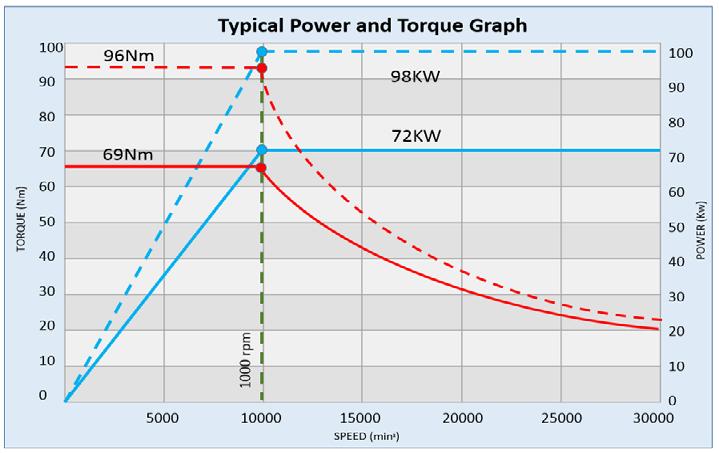
RPM stated may be outside of most machine tools in the smaller sizes, adjust the surface speed but maintain the Fz For best results use the peak power of the specific machine torque chart. Typically 10hp is required to remove 45 cubic inches of material (MRR).
Eg. >> (Ae x Ap x Feed) >> Therefore Full slotting 1" dia: 1 x 1 x 355 = 355 cubic inches, so it needs a min of 78hp.
Larger cuts and chip load consume more power.
Review the power chart of each machine to determine MAX power for ultimate performance.
Example below shows peak power @ 10,000 rpm.
The new coolant supply is designed for MQL as well as normal emulsion coolant on the same data.
Ensure max MQL flow prior to cutting.
rpm
Refer to the SGS APEX: Application Expert for complete technical information www.kyocera-sgstool.com/apex
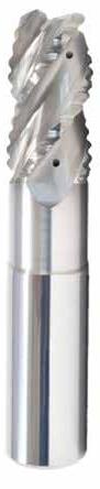
S-Carb APR
3 Flute Advanced Productivity Rougher
43APR-3
METRIC SERIES
• Ultra high-productivity rougher for Aluminum alloys, specifically for aircraft components
• Designed for high material removal rates (MRR)
• 3 flute variable geometry with side exit coolant holes
• Open fluting for deep slotting and profiling
• Recommended for materials ≤ 150 Bhn (≤ 7 HRc)
*Variable Helix
= –0,010/–0,100
= h 6
RPM stated may be outside of most machine tools in the smaller sizes, adjust the surface speed but maintain the Fz For best results use the peak power of the specific machine torque chart. Typically 10kw is required to remove 1 litre of material (MMR).
Eg. >> (Ae x Ap x Feed) / 1000000 >> Therefore Full slotting Ø25: 25 x 25 x 7333 = 4.58 Litres so it needs a min of 46Kw.
Larger cuts and chip load consume more power.
Review the power chart of each machine to determine MAX power for ultimate performance.
Example below shows peak power @ 10,000 rpm.
APR
Refer to the SGS APEX: Application Expert for complete technical information www.kyocera-sgstool.com/apex
The APR-4 design is for ultimate metal removal but typicaly requires more power, and is also better suited to horizontal machines.
The new coolant supply is designed for MQL as well as normal emulsion coolant on the same data.
Ensure max MQL flow prior to cutting.
10000 rpm
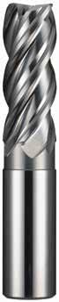
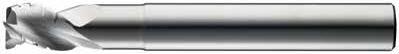
S-Carb APR
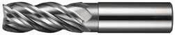
4 Flute Advanced Productivity Rougher
43APR-4
METRIC SERIES
• Ultra high-productivity rougher for Aluminum alloys, specifically for aircraft components
• Designed for high material removal rates (MRR)
• 4 flute variable geometry with side exit coolant holes
• Open fluting for deep slotting and profiling
• Recommended for materials ≤ 150 Bhn (≤ 7 HRc)
TOLERANCES (mm)
20–25 DIAMETER
= –0,010/–0,100
= h 6
= +/–0,05
RPM stated may be outside of most machine tools in the smaller sizes, adjust the surface speed but maintain the Fz For best results use the peak power of the specific machine torque chart.
Typically 10kw is required to remove 1 litre of material (MMR).
Eg. >> (Ae x Ap x Feed) / 1000000 >> Therefore Full slotting Ø25: 25 x 25 x 7333 = 4.58 Litres so it needs a min of 46Kw.
Larger cuts and chip load consume more power.
Review the power chart of each machine to determine MAX power for ultimate performance.
Example below shows peak power @ 10,000 rpm.
Cutting Conditions
Refer to the SGS APEX: Application Expert for complete technical information
www.kyocera-sgstool.com/apex
The APR-4 design is for ultimate metal removal but typicaly requires more power, and is also better suited to horizontal machines.
The new coolant supply is designed for MQL as well as normal emulsion coolant on the same data.
Ensure max MQL flow prior to cutting.
4 Flute Advanced Productivity Finisher
43APF FRACTIONAL SERIES
• Ultra high-productivity finisher for Aluminum alloys, specifically for aircraft components
• Two levels of chatter suppression: variable helix and indexing
• Designed for single axial pass semifinishing and finishing
• Polished flutes maximize chip evacuation and provides enhanced finish
• Recommended for materials ≤ 150 Bhn (≤ 7 HRc)
Available on request: • JetStream Technology
Recommended Cutting Conditions
2024, 5052, 5086, 6061, 6063, 7075
N ALUMINUM ALLOYS
ALUMINUM ALLOYS (LITHIUM)*
2090, 2091, 2099, 2195, 2199, 2297, 8090
88 HRb
150 Bhn
Bhn (Brinell) HRb (Rockwell B) surface speed is dependent on machine spindle and fixturing balancing is recommended at ultra high surface speeds tool life may be reduced when machining Lithium Alloys rpm = Vc x 3.82 / DC ipm = Fz x 4 x rpm maximum recommended depths shown reduce speed and feed for materials harder than listed finish cuts typically require reduced feed and cutting depths of 0.02 X DC maximum ramp angle = 6˚ (feed rate = 50%) plunging not recommended
Refer to the SGS APEX: Application Expert for complete technical information www.kyocera-sgstool.com/apex
APF
4 Flute Advanced Productivity Finisher
43MAPF
METRIC SERIES
• Ultra high-productivity finisher for Aluminum alloys, specifically for aircraft components
• Two levels of chatter suppression: variable helix and indexing
• Designed for single axial pass semifinishing and finishing
• Polished flutes maximize chip evacuation and provides enhanced finish
• Recommended for materials ≤ 150 Bhn (≤ 7 HRc)
Available on request: • JetStream Technology
TOLERANCES (mm)
6–25 DIAMETER
ALUMINUM ALLOYS
2024, 5052, 5086, 6061, 6063, 7075
ALUMINUM ALLOYS (LITHIUM)*
2090, 2091, 2099, 2195, 2199, 2297, 8090
Bhn (Brinell) HRb (Rockwell B) surface speed is dependent on machine spindle and fixturing balancing is recommended at ultra high surface speeds *tool life may be reduced when machining Lithium Alloys rpm = (Vc x 1000) / (DC x 3.14) mm/min = Fz x 4 x rpm maximum recommended depths shown reduce speed and feed for materials harder than listed finish cuts typically require reduced feed and cutting depths of 0.02 X DC maximum ramp angle = 6˚ (feed rate = 50%) plunging not recommended
Refer to the SGS APEX: Application Expert for complete technical information www.kyocera-sgstool.com/apex
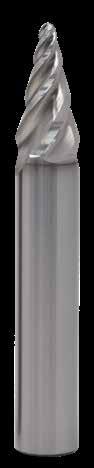
Multi-Flute Tapered (Circle Segment) Form Tools

43APF-B
METRIC SERIES
• Designed to significantly improve traditional ball end applications
• Highly efficient at finishing and semifinishing profiling
• Main application areas include profiling and pocket milling
• Especially suited to machining deep pockets and hard-to-reach areas without using long-reach tools
• Their versatility also allows for machining profiles and blends with one tool
• Recommended for materials ≤ 150 Bhn (≤ 7 HRc)
rpm = (Vc x 1000) / (DC x 3.14)
Feed= Fz x No. of flutes x rpm
Adjust speed and feed cutting
Adjust rates according to cutting area of tool being used
Recommended Cutting Conditions

Avoid using tip of the tool where possible due to reduced chip space
Be aware of max cut Ae, especially on the lower portion of the tool
Refer to the SGS APEX: Application Expert for complete technical information www.kyocera-sgstool.com/apex
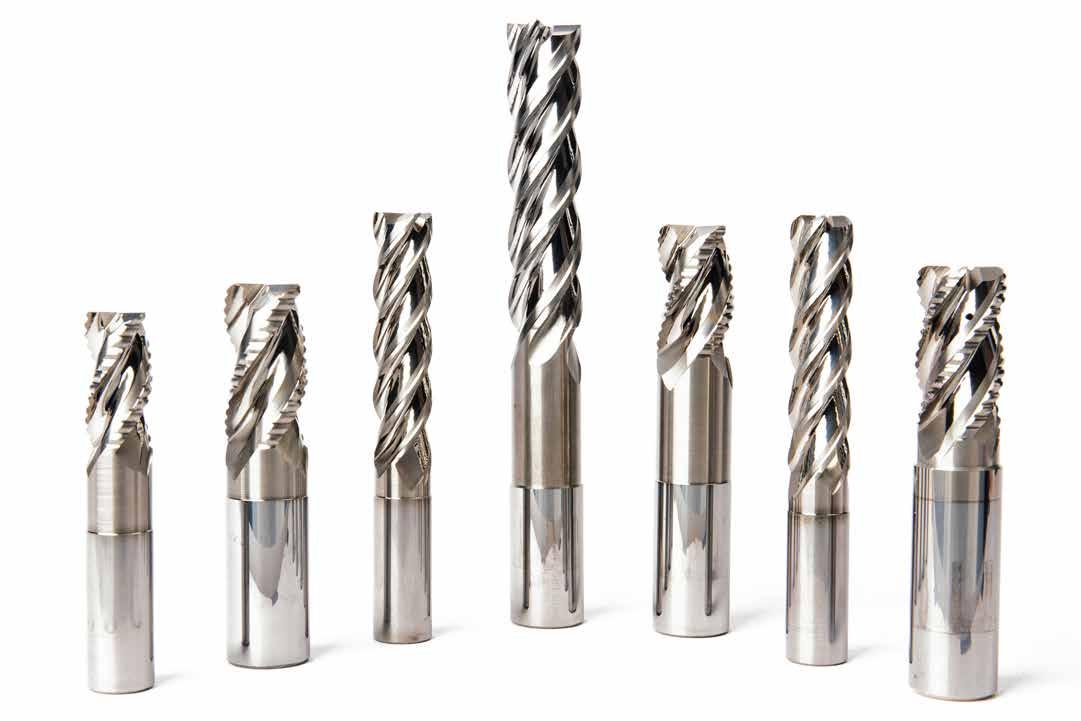
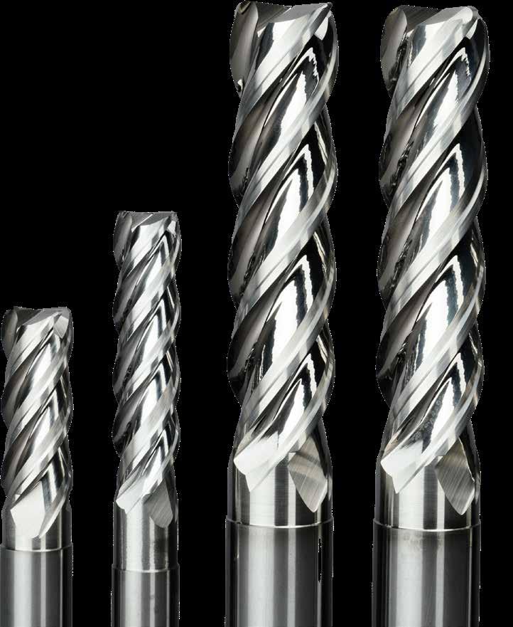
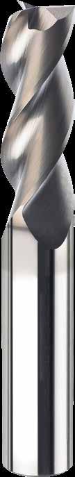
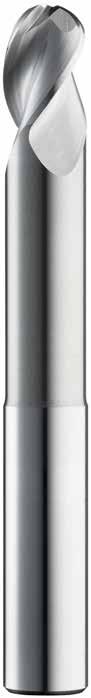
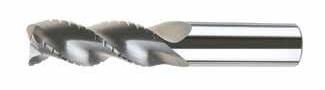
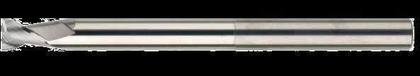
S-CARB
HIGH PERFORMANCE END MILLS
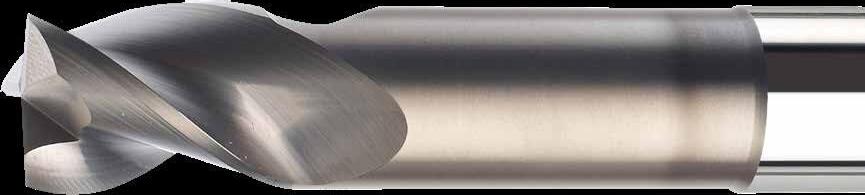
The original, symmetrical flute design features an engineered flute form that provides high performance results through a full range of machining conditions. These tools are designed for aggressive aluminum, non-ferrous, and non-metallic machining requiring a high level of material removal.
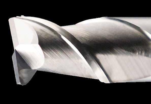
ENGINEERED FLUTE DESIGN
• Effective chip removal at high feed rates
• Lower cutting forces than comparable products
• Improved balance at high spindle speeds
• Improved workpiece finish through better balance
• More effective plunging vs. conventional designs
CIRCULAR LAND
• Increased control at various speed and feed levels
• Reduced chatter
VARIOUS REACH, NECK AND END OPTIONS AVAILABLE
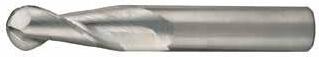
• Ball End design for complex workpieces
• Necked design with blended diameter transitions provide clearance to reach
• Short flutes for maximum rigidity
• Axial slotting up to 1xD
SERIES 43 METRIC TOOLS AVAILABLE WITH POLISHED FLUTES
• Increased control at various speed and feed levels
• Reduced chatter
S-CARB END MILLS ARE ENGINEERED FOR ALUMINUM , NON-FERROUS & NON-METALLIC MATERIALS


Maximum RPM Capability
of
Tolerance
T i -NAMITE-B COATING TECHNOLOGY
Slotting Capability: 3-Flute End Mills
Maximum Feed Rate Achieved at 100% Spindle Load on a 30 hp Vertical Mill in 6061 Aluminum @ 10,000
Available with TiB2 Coating (Titanium Diboride). This ceramic based coating ensures a smooth surface and a low affinity to cold welding or edge build-up, which makes it optimal for aluminum and copper applications. It has high toughness and high hardness.
• Hardness: 4000 HV
• Oxidation Temperature: 850°C / 1562°F
• Coefficient of Friction: 0.10 – 0.20
• Thickness: 1 – 2 Microns (based on tool diameter)
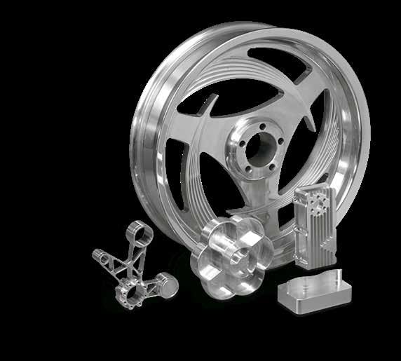
S-CARB HIGH PERFORMANCE END MILLS ARE IDEAL FOR CYCLE TIME REDUCTION IN TARGET APPLICATIONS SUCH AS:
AEROSPACE
• Structural components
• Wheels
AUTOMOTIVE / MOTORBIKE
• Performance aluminum wheels
• Non-ferrous housings, transmissions, manifolds, electronic pumps
MOLD & DIE
• Non-ferrous mold cavities
FIREARMS
• Aluminum components
SEMICONDUCTOR
• Aluminum vacuum chambers
43
3 Flute Square & Corner Radius

• Circular land allows for increased control at various speed and feed rates and reduces chatter
• Symmetrical end gashing for excellent balance at high speeds and aggressive plunging capability
• Open fluting for deep slotting and profiling
• Enhanced corner geometry with tight tolerance corner radii
• Recommended for materials ≤ 150 Bhn (≤ 7 HRc)
1/4 3/8 2-1/2 1/4 .060 35578 35668
1/4 1/2 2-1/2 1/4 – 34824 34859 1/4 3/4 2-1/2 1/4 – 34704 34731
1/4 3/4 2-1/2 1/4 .010 34773 34795
1/4 3/4 2-1/2 1/4 .015 35579 35669
1/4 3/4 2-1/2 1/4 .030 34774 34796
1/4 3/4 2-1/2 1/4 .060 35580 35670
1/4 1 3 1/4 – 34825 34860
1/4 1 3 1/4 .010 35581 35671
1/4 1 3 1/4 .015 35582 35672
1/4 1 3 1/4 .030 35583 35673
TOLERANCES (inch)
1/8–3/16 DIAMETER
1/4–3/8 DIAMETER
1/2–5/8 DIAMETER
= +0.0000/–0.00043
= h 6
3/4–1 DIAMETER
= h 6
5/16 7/16 2 5/16
3 Flute Square & Corner Radius
TOLERANCES (inch)
1/8–3/16 DIAMETER
DC = +0.0000/–0.00032
DCON = h 6
RE = +0.0000/–0.0020
1/4–3/8 DIAMETER
DC = +0.0000/–0.00035
DCON = h 6
RE = +0.0000/–0.0020
1/2–5/8 DIAMETER
DC = +0.0000/–0.00043
DCON = h 6
RE = +0.0000/–0.0020
3/4–1 DIAMETER
DC = +0.0000/–0.00051
DCON = h 6
RE = +0.0000/–0.0020
NON-FERROUS
3/8 1-1/2 4 3/8 .010 35592 35682 3/8 1-1/2 4 3/8 .015 35593 35683 3/8 1-1/2 4 3/8 .030 35594 35684 3/8 1-1/2 4 3/8 .060 35595 35685
3/8 1-1/2 4 3/8 .090 35596 35686 3/8 2 4 3/8 – 34828 34863 1/2 5/8 2-1/2 1/2 – 34712 34739
1/2 5/8 3 1/2 .010 35597 35687
1/2 5/8 3 1/2 .015 35598 35688
1/2 5/8 3 1/2 .030 35599 35689 1/2 5/8 3 1/2 .060 35600 35690
1/2 5/8 3 1/2 .090 35601 35691
1/2 5/8 3 1/2 .120 35602 35692
1/2 1 3 1/2 – 34830 34865 1/2 1 3 1/2 .010 35603 35693 1/2 1 3 1/2 .015 35604 35694
• Circular land allows for increased control at various speed and feed rates and reduces chatter
• Symmetrical end gashing for excellent balance at high speeds and aggressive plunging capability
• Open fluting for deep slotting and profiling
• Enhanced corner geometry with tight tolerance corner radii
• Recommended for materials ≤ 150 Bhn (≤ 7 HRc)
34803 1/2 1-1/4 3-1/4 1/2 .120 32766 32830
1/2 1-5/8 4 1/2 – 34831 34866
1/2 1-5/8 4 1/2 .010 35610 35700 1/2 1-5/8
1/2 .015 35611 35701 continued on next page
3
Flute Square & Corner Radius
• Circular land allows for increased control at various speed and feed rates and reduces chatter
• Symmetrical end gashing for excellent balance at high speeds and aggressive plunging capability
• Open fluting for deep slotting and profiling
• Enhanced corner geometry with tight tolerance corner radii
• Recommended for materials ≤ 150 Bhn (≤ 7 HRc)
5/8 3/4 3-1/2 5/8 .060 35623 35713
5/8 3/4 3-1/2 5/8 .090 35624 35714
5/8 3/4 3-1/2 5/8 .120 35625 35715
5/8 1-5/8 3-3/4 5/8 – 34717 34744
5/8 1-5/8 3-3/4 5/8 .030 34782 34804
5/8 1-5/8 3-3/4 5/8 .060 34783 34805
5/8 1-5/8 3-3/4 5/8 .090 34784 34806
5/8 1-5/8 3-3/4 5/8 .120 35626 35716
5/8 2-1/8 4 5/8 – 34833 34868
5/8 2-1/2 5 5/8 – 34718 34745
5/8 3-1/4 6 5/8 – 34834 34869
5/8 3-3/4 6 5/8 – 34719 34746
3/4 1 3 3/4 – 34720 34747
3/4 1 4 3/4 .030 35627 35717
3/4 1 4 3/4 .060 35628 35718
3/4 1 4 3/4 .090 35629 35719
3/4 1 4 3/4 .120 35630 35720
3/4 1 4 3/4 .190 35631 35721
3/4 1 4 3/4 .250 35632 35722
3/4 1-5/8 4 3/4 – 34721 34748
3/4 1-5/8 4 3/4 .030 34785 34807 continued on next page
TOLERANCES (inch)
1/8–3/16 DIAMETER
= +0.0000/–0.00032
= h 6
= +0.0000/–0.0020
1/4–3/8 DIAMETER
= +0.0000/–0.00035
= h 6
= +0.0000/–0.0020
1/2–5/8 DIAMETER
= +0.0000/–0.00043
= h 6
3/4–1 DIAMETER
= +0.0000/–0.00051
= h 6
3 Flute Square & Corner Radius
TOLERANCES (inch)
1/8–3/16 DIAMETER
DC = +0.0000/–0.00032
DCON = h 6
RE = +0.0000/–0.0020
1/4–3/8 DIAMETER
DC = +0.0000/–0.00035
DCON = h 6
RE = +0.0000/–0.0020
1/2–5/8 DIAMETER
DC = +0.0000/–0.00043
DCON = h 6
RE = +0.0000/–0.0020
3/4–1 DIAMETER
DC = +0.0000/–0.00051
DCON = h 6
RE = +0.0000/–0.0020
NON-FERROUS
• Circular land allows for increased control at various speed and feed rates and reduces chatter
• Symmetrical end gashing for excellent balance at high speeds and aggressive plunging capability
• Open fluting for deep slotting and profiling
• Enhanced corner geometry with tight tolerance corner radii
• Recommended for materials ≤ 150 Bhn (≤ 7 HRc)
3 Flute Square & Corner Radius Long Reach
43L • 43LC
FRACTIONAL SERIES
• Circular land allows for increased control at various speed and feed rates and reduces chatter
• Symmetrical end gashing for excellent balance at high speeds and aggressive plunging capability
• Open fluting for deep slotting and profiling
• Necked design with blended diameter transitions provide clearance to reach
• Enhanced corner geometry with tight tolerance corner radii
• Recommended for materials ≤ 150 Bhn (≤ 7 HRc)

1-1/2 .230 – 32703 32728
1/4 3/8 4 1/4 1-1/2 .230 .010 32755 32819
1/4 3/8 4 1/4 1-1/2 .230 .030 32756 32820
1/4 3/8 4 1/4 2-1/8 .230 – 32704 32729
1/4 3/8 4 1/4 2-1/8 .230 .010 32757 32821 1/4 3/8 4 1/4 2-1/8 .230 .030 32758 32822
5/16 7/16 4 5/16 1-1/8 .292 – 32705 32730
5/16 7/16 4 5/16 1-1/8 .292 .030 32759 32823
5/16 7/16 4 5/16 2-1/8 .292 – 32706 32731
5/16 7/16 4 5/16 2-1/8 .292 .030 32760 32824
3/8 1/2 3 3/8 1-1/8 .355 .015 35791 36239
3/8 1/2 3 3/8 1-1/8 .355 .090 35792 36240
3/8 1/2 4 3/8 1-1/8 .355 – 32707 32732
3/8 1/2 4 3/8 1-1/8 .355 .030 32762 32826
3/8
continued on next page
TOLERANCES (inch)
1/8–3/16 DIAMETER
DC = +0.0000/–0.00032
DCON = h 6
= +0.0000/–0.0020
1/4–3/8 DIAMETER
DC = +0.0000/–0.00035
DCON = h 6 RE = +0.0000/–0.0020
1/2–5/8 DIAMETER DC = +0.0000/–0.00043
DCON = h 6
= +0.0000/–0.0020
3/4–1 DIAMETER
DC = +0.0000/–0.00051
DCON = h 6
RE = +0.0000/–0.0020
NON-FERROUS
3 Flute Square & Corner Radius Long Reach
TOLERANCES (inch)
1/8–3/16 DIAMETER
DC = +0.0000/–0.00032
DCON = h 6
RE = +0.0000/–0.0020
1/4–3/8 DIAMETER
DC = +0.0000/–0.00035
DCON = h 6
RE = +0.0000/–0.0020
1/2–5/8 DIAMETER
DC = +0.0000/–0.00043
DCON = h 6
RE = +0.0000/–0.0020
3/4–1 DIAMETER
DC = +0.0000/–0.00051
DCON = h 6
RE = +0.0000/–0.0020
NON-FERROUS
6 1/2 3-3/8 .480 .120 32778 32842
1/2 5/8 6 1/2 4-1/4 .480 – 32697 34894
5/8 3/4 4 5/8 1-3/4 .605 – 32712 32737
5/8 3/4 4 5/8 1-3/4 .605 .030 32779 32843
5/8 3/4 4 5/8 1-3/4 .605 .060 32780 32844
5/8 3/4 4 5/8 1-3/4 .605 .090 32781 32845
5/8 3/4 4 5/8 1-3/4 .605 .120 32782 32846
5/8 3/4 4 5/8 2-3/8 .605 – 32713 32738
5/8 3/4 4 5/8 2-3/8 .605 .030 32783 32847
5/8 3/4 4 5/8 2-3/8 .605 .060 32784 32848
5/8 3/4 4 5/8 2-3/8 .605 .090 32785 32849
5/8 3/4 4 5/8 2-3/8 .605 .120 32786 32850
5/8 3/4 6 5/8 3-3/8 .605 – 32714 32739
5/8 3/4 6 5/8 3-3/8 .605 .030 32787 32851
5/8 3/4 6 5/8 3-3/8 .605 .060 32788 32852
5/8 3/4 6 5/8 3-3/8 .605 .090 32789 32853
5/8 3/4 6 5/8 3-3/8 .605 .120 32790 32854
5/8 3/4 6 5/8 4-3/8 .605 – 32698 34895
3/4 1 4 3/4 1-3/4 .730 – 32715 32740
3/4 1 4 3/4 1-3/4 .730 .030 32791 32855
3/4 1 4 3/4 1-3/4 .730 .060 32792 32856
3/4 1 4 3/4 1-3/4 .730 .090 32793 32857
3/4 1 4 3/4 1-3/4 .730 .120 32794 32858
3/4 1 4 3/4 2 .730 .190 35803 36251
3/4 1 4 3/4 2 .730 .250 35804 36252
3/4 1 6 3/4 2-3/8 .730 – 32716 32741
3/4 1 6 3/4 2-3/8 .730 .030 32795 32859
continued on next page
• Circular land allows for increased control at various speed and feed rates and reduces chatter
• Symmetrical end gashing for excellent balance at high speeds and aggressive plunging capability
• Open fluting for deep slotting and profiling
• Necked design with blended diameter transitions provide clearance to reach
• Enhanced corner geometry with tight tolerance corner radii
• Recommended for materials ≤ 150 Bhn (≤ 7 HRc)
3 Flute Square & Corner Radius Long Reach
FRACTIONAL SERIES
• Circular land allows for increased control at various speed and feed rates and reduces chatter
• Symmetrical end gashing for excellent balance at high speeds and aggressive plunging capability
• Open fluting for deep slotting and profiling
• Necked design with blended diameter transitions provide clearance to reach
• Enhanced corner geometry with tight tolerance corner radii
• Recommended for materials ≤ 150 Bhn (≤ 7 HRc)
TOLERANCES (inch)
1/8–3/16 DIAMETER
= +0.0000/–0.00032
= h 6
1/4–3/8 DIAMETER
1/2–5/8 DIAMETER
+0.0000/–0.00043
= h 6
= +0.0000/–0.0020
3/4–1 DIAMETER DC = +0.0000/–0.00051
DCON = h 6 RE = +0.0000/–0.0020
NON-FERROUS
3 Flute Corner Radius Extra Long Reach
TOLERANCES (inch)
1/4–3/8 DIAMETER
DC = +0.0000/–0.00035
DCON = h 6
RE = +0.0000/–0.0020
1/2–5/8 DIAMETER
DC = +0.0000/–0.00043
DCON = h 6
RE = +0.0000/–0.0020
3/4–1 DIAMETER
DC = +0.0000/–0.00051
DCON = h 6
RE = +0.0000/–0.0020
NON-FERROUS
• Circular land allows for increased control at various speed and feed rates and reduces chatter
• Symmetrical end gashing for excellent balance at high speeds and aggressive plunging capability
• Open fluting for deep slotting and profiling
• Necked design with blended diameter transitions provide clearance to reach
• Enhanced corner geometry with tight tolerance corner radii
• Recommended for materials ≤ 150 Bhn (≤ 7 HRc)
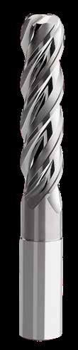
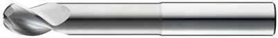
3 Flute Ball End
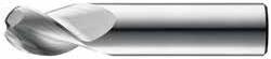
• Circular land allows for increased control at various speed and feed rates and reduces chatter
• Open fluting for deep slotting and profiling
• Ball end design ideal for finishing operations in complex workpieces
• Recommended for materials ≤ 150 Bhn (≤ 7 HRc)
TOLERANCES (inch)
1/4–3/8 DIAMETER
1/2–5/8 DIAMETER
3/4–1 DIAMETER
= +0.0000/–0.00051
= h 6
= +0.0005/–0.0005
NON-FERROUS
3
Flute Ball End Long & Extra Long Reach
TOLERANCES (inch)
1/4–3/8 DIAMETER
DC = +0.0000/–0.00035
DCON = h 6
RE = +0.0005/–0.0005
1/2–5/8 DIAMETER
DC = +0.0000/–0.00043
DCON = h 6
RE = +0.0005/–0.0005
3/4–1 DIAMETER
DC = +0.0000/–0.00051
DCON = h 6
RE = +0.0005/–0.0005
NON-FERROUS
TOLERANCES (inch)
1/4–3/8 DIAMETER
DC = +0.0000/–0.00035
DCON = h 6
RE = +0.0005/–0.0005
1/2–5/8 DIAMETER
DC = +0.0000/–0.00043
DCON = h 6
RE = +0.0005/–0.0005
3/4–1 DIAMETER
DC = +0.0000/–0.00051
DCON = h 6
RE = +0.0005/–0.0005
NON-FERROUS
• Open fluting for deep slotting and profiling
• Necked design with blended diameter transitions provide clearance to reach
• Circular land allows for increased control at various speed and feed rates and reduces chatter
• Ball end design ideal for finishing operations in complex workpieces
• Recommended for materials ≤ 150 Bhn (≤ 7 HRc)
FRACTIONAL SERIES 43EB
FRACTIONAL SERIES
• Circular land allows for increased control at various speed and feed rates and reduces chatter
• Open fluting for deep slotting and profiling
• Necked design with blended diameter transitions provide clearance to reach
• Ball end design ideal for finishing operations in complex workpieces
• Recommended for materials ≤ 150 Bhn (≤ 7 HRc) 43LB
3 Flute Ball Rougher Chip Breaker
43CB
FRACTIONAL SERIES
• Circular land allows for increased control at various speed and feed rates and reduces chatter
• Symmetrical end gashing for excellent balance at high speeds and aggressive plunging capability
• Chip breakers reduce machine loads up to 15% for increased roughing feed rate capability
• Open fluting for deep slotting and profiling
• Recommended for materials ≤ 150 Bhn (≤ 7 HRc)
1/2 2-1/2 1/4 .020 33391 33451 1/4 3/4 2-1/2 1/4 .020 33392 33452 1/4 1 3 1/4 .020 33393 33453 1/4 1-1/4 3-1/2 1/4 .020 33394 33454 1/4 1-3/4 4 1/4 .020 33395 33455
5/16 7/16 2-1/2 5/16 .020 33396 33456 5/16 11/16 2-1/2 5/16 .020 33397 33457
5/16 1 3 5/16 .020 33398 33458 5/16 2-1/8 4 5/16 .020 33400 33460
3/8 1/2 3 3/8 .020 33401 33461
3/8 1 2-1/2 3/8 .020 34300 34305
3/8 1-1/4 3-1/2 3/8 .020 33402 33462
3/8 1-1/2 4 3/8 .020 33403 33463
3/8 2 4 3/8 .020 33404 33464
1/2 5/8 3 1/2 .030 33406 33466 1/2 1 3 1/2 .030 33407 33467
1/2 1-1/4 3-1/4 1/2 .030 34301 34306
1/2 1-5/8 4 1/2 .030 33408 33468
1/2 2 4 1/2 .030 33409 33469 1/2 2-1/2 5 1/2 .030 33410 33470 1/2 3-1/8 6 1/2 .030 33411 33471
5/8 3/4 3-1/2 5/8 .030 33412 33472
5/8 1-5/8 3-3/4 5/8 .030 34302 34307
5/8 2-1/8 4 5/8 .030 33413 33473
5/8 3-1/4 6 5/8 .030 33415 33475
5/8 3-3/4 6 5/8 .030 33416 33476
3/4 1 4 3/4 .030 33417 33477
3/4 1-5/8 4 3/4 .030 34303 34308
3/4 2-1/4 5 3/4 .030 33418 33478
3/4 3-1/4 6 3/4 .030 33419 33479
3/4 4 6 3/4 .030 33420 33480 1 1-1/4 5 1 .030 33421 33481 1 2 4-1/2 1 .030 34304 34309 1 2-5/8 6 1 .030 33422 33482 1 3-1/4 6 1 .030 33423 33483 1 4-1/8 7 1 .030 33424 33484
1/2–5/8 DIAMETER
3/4–1 DIAMETER
TOLERANCES (inch)
1/4–3/8 DIAMETER
DC = +0.0000/–0.00035
DCON = h 6
RE = +0.0000/–0.0020
1/2–5/8 DIAMETER
DC = +0.0000/–0.00043
DCON = h 6
RE = +0.0000/–0.0020
3/4–1 DIAMETER
DC = +0.0000/–0.00051
DCON = h 6
NON-FERROUS
3 Flute Ball Rougher Chip Breaker Long Reach
FRACTIONAL SERIES
• Circular land allows for increased control at various speed and feed rates and reduces chatter
• Symmetrical end gashing for excellent balance at high speeds and aggressive plunging capability
• Chip breakers reduce machine loads up to 15% for increased roughing feed rate capability
• Open fluting for deep slotting and profiling
• Necked design with blended diameter transitions provide clearance to reach
• Recommended for materials ≤ 150 Bhn (≤ 7 HRc)
S-Carb 43
Cutting Conditions
Series 43CR, 43CB, 43LC, 43, 43L, 43LCB, 43B, 43LB, 43ELB, 43EC Fractional Hardness
ALUMINUM ALLOYS
2024, 5052, 5086, 6061, 6073, 7075
COPPER ALLOYS
COPPER ALLOYS
Beryllium Copper C110, Malleable Bronze, Tin Bronze
PLASTICS
ABS, Polycarbonate, PVC, Polypropylene
Bhn (Brinell) HRc (Rockwell C) HRb (Rockwell B) HSM (High Speed Machining)
rpm = Vc x 3.82 / DC
ipm = Fz x 3 x rpm
reduce speed and feed for materials harder than listed reduce cut depth and feed by 50% for long flute and long reach tools reduce feed and Ae when finish milling (.02 x DC maximum)
Refer to the SGS APEX: Application Expert for
3 Flute Square & Corner Radius
TOLERANCES (mm)
≤6 DIAMETER
DC = +0,000/–0,008
DCON = h 6
RE = +0,000/–0,050
>6–10 DIAMETER
DC = +0,000/–0,009
DCON = h 6
RE = +0,000/–0,050
>10–18 DIAMETER
DC = +0,000/–0,011
DCON = h 6
RE = +0,000/–0,050
>18–20 DIAMETER
DC = +0,000/–0,013
DCON = h 6
RE = +0,000/–0,050
NON-FERROUS
6,0 24,0 75,0 6,0 0,5
6,0 24,0 75,0 6,0 1,0
• Circular land allows for increased control at various speed and feed rates and reduces chatter
• Symmetrical end gashing for excellent balance at high speeds and aggressive plunging capability
• Open fluting for deep slotting and profiling
• Enhanced corner geometry with tight tolerance corner radii
• Recommended for materials ≤ 150 Bhn (≤ 7 HRc)
– 44893
– 44844
– 44845
8,0 19,0 63,0 8,0 – 44703 44717
8,0 19,0 63,0 8,0 0,3
8,0 19,0 63,0 8,0 0,5
8,0 19,0 63,0 8,0 1,0
8,0 19,0
– 44846
– 44847
– 44848
44852 8,0 32,0 75,0 8,0 2,0
44705 44719
44853 10,0 22,0 72,0 10,0
44854
44855
44856 10,0 22,0 72,0 10,0 1,5
44857 10,0 40,0 100,0 10,0
44896 10,0 40,0 100,0 10,0 0,5
44858 continued on next page
METRIC S-Carb 43
3 Flute Square & Corner Radius
43M • 43MCR METRIC SERIES
• Circular land allows for increased control at various speed and feed rates and reduces chatter
• Symmetrical end gashing for excellent balance at high speeds and aggressive plunging capability
• Open fluting for deep slotting and profiling
• Enhanced corner geometry with tight tolerance corner radii
• Recommended for materials ≤ 150 Bhn (≤ 7 HRc)
(mm)
DIAMETER
= +0,000/–0,008
= +0,000/–0,050
DIAMETER
DIAMETER
DIAMETER
44877
on next page
NON-FERROUS
3 Flute Square & Corner Radius
TOLERANCES (mm)
≤6 DIAMETER
DC = +0,000/–0,008
DCON = h 6
RE = +0,000/–0,050
>6–10 DIAMETER
DC = +0,000/–0,009
DCON = h 6
RE = +0,000/–0,050
>10–18 DIAMETER
DC = +0,000/–0,011
DCON = h 6
RE = +0,000/–0,050
>18–20 DIAMETER
DC = +0,000/–0,013
DCON = h 6
RE = +0,000/–0,050
NON-FERROUS
• Circular land allows for increased control at various speed and feed rates and reduces chatter
• Symmetrical end gashing for excellent balance at high speeds and aggressive plunging capability
• Open fluting for deep slotting and profiling
• Enhanced corner geometry with tight tolerance corner radii
• Recommended for materials ≤ 150 Bhn (≤ 7 HRc)
3 Flute Square & Corner Radius
43ML •
43MLC
SERIES
• Circular land allows for increased control at various speed and feed rates and reduces chatter
• Symmetrical end gashing for excellent balance at high speeds and aggressive plunging capability
• Open fluting for deep slotting and profiling
• Necked design with blended diameter transitions provide clearance to reach
• Enhanced corner geometry with tight tolerance corner radii
• Recommended for materials ≤ 150 Bhn (≤ 7 HRc)
continued on next page
TOLERANCES (mm)
6 DIAMETER
DC = +0,000/–0,008
= h 6
>6–10 DIAMETER
= +0,000/–0,009
= h 6 RE = +0,000/–0,050
>10–18 DIAMETER
DC = +0,000/–0,011
DCON = h 6
RE = +0,000/–0,050
>18–20 DIAMETER
DC = +0,000/–0,013
DCON = h 6
RE = +0,000/–0,050
NON-FERROUS
3 Flute Square & Corner Radius
TOLERANCES (mm)
6 DIAMETER
DC = +0,000/–0,008
DCON = h 6
>6–10 DIAMETER
DC = +0,000/–0,009
DCON = h 6
RE = +0,000/–0,050
>10–18 DIAMETER
DC = +0,000/–0,011
DCON = h 6
RE = +0,000/–0,050
>18–20 DIAMETER
DC = +0,000/–0,013
DCON = h 6
RE = +0,000/–0,050
NON-FERROUS
• Circular land allows for increased control at various speed and feed rates and reduces chatter
• Symmetrical end gashing for excellent balance at high speeds and aggressive plunging capability
• Open fluting for deep slotting and profiling
• Necked design with blended diameter transitions provide clearance to reach
• Enhanced corner geometry with tight tolerance corner radii
• Recommended for materials ≤ 150 Bhn (≤ 7 HRc)
S-Carb 43
3 Flute Ball End
43MB
• Circular land allows for increased control at various speed and feed rates and reduces chatter
• Open fluting for deep slotting and profiling
• Ball end design ideal for finishing operations in complex workpieces
• Recommended for materials ≤ 150 Bhn (≤ 7 HRc)
= 1/2 Cutting Diameter (DC)
TOLERANCES (mm)
3 DIAMETER
= +0,000/–0,006
= h 6
+0,0127/–0,0127
>3–6 DIAMETER
= +0,000/–0,008
= h 6
>6–10 DIAMETER
+0,000/–0,009
+0,0127/–0,0127
>10–18 DIAMETER
= +0,000/–0,011
= h 6
= +0,0127/–0,0127
>18–25 DIAMETER
DC = +0,000/–0,013
DCON = h 6
= +0,0127/–0,0127
NON-FERROUS
3 Flute Ball End Long Reach
TOLERANCES (mm)
3 DIAMETER
DC = +0,000/–0,006
DCON = h 6
RE = +0,0127/–0,0127
>3–6 DIAMETER
DC = +0,000/–0,008
DCON = h 6
RE = +0,0127/–0,0127
>6–10 DIAMETER
DC = +0,000/–0,009
DCON = h 6
RE = +0,0127/–0,0127
>10–18 DIAMETER
DC = +0,000/–0,011
DCON = h 6
RE = +0,0127/–0,0127
>18–25 DIAMETER
DC = +0,000/–0,013
DCON = h 6
RE = +0,0127/–0,0127
NON-FERROUS
RE = 1/2 Cutting Diameter (DC)
• Circular land allows for increased control at various speed and feed rates and reduces chatter
• Open fluting for deep slotting and profiling
• Ball end design ideal for finishing operations in complex workpieces
• Recommended for materials ≤ 150 Bhn (≤ 7 HRc)
S-Carb 43
3 Flute Rougher Chip Breaker
43MCB
METRIC
SERIES
• Circular land allows for increased control at various speed and feed rates and reduces chatter
• Symmetrical end gashing for excellent balance at high speeds and aggressive plunging capability
• Chip breakers reduce machine loads up to 15% for increased roughing feed rate capability
• Open fluting for deep slotting and profiling
• Recommended for materials ≤ 150 Bhn (≤ 7 HRc)
TOLERANCES (mm) >6–10 DIAMETER
DIAMETER
Series 43M, 43MB, 43MBL, 43MCR, 43ML, 43MLC, 43MCB Metric Hardness
ALUMINUM ALLOYS
2024, 5052, 5086, 6061, 6073, 7075
ALUMINUM DIE CAST ALLOYS (HIGH SILICONE)
A-390,
COPPER ALLOYS
COPPER ALLOYS
Beryllium Copper C110, Manganese Bronze, Tin Bronze
PLASTICS
Polycarbonate, PVC, Polypropylene
Bhn (Brinell) HRc (Rockwell C) HRb (Rockwell B) HSM (High Speed Machining) rpm = (Vc x 1000) / (DC x 3.14) mm/min = Fz x 3 x rpm reduce speed and feed for materials harder than listed reduce cut depth and feed by 50% for long flute and long reach tools reduce feed and Ae when finish milling (.02 x DC maximum)
S-Carb 43
www.kyocera-sgstool.com/apex
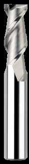
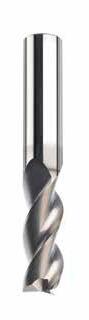
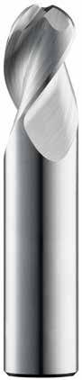
2 Flute Square Regular & Long Reach
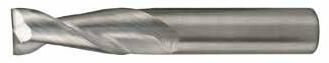
FRACTIONAL SERIES
• Circular land reduces edge aggressiveness for varied
and feed rates
• 2 Flutes effectively manage the large size and volume of chips produced during the aggressive machining process
• Excellent balance at high speeds and aggressive plunging capability
• Recommended for materials ≤ 150 Bhn (≤ 7 HRc)
FRACTIONAL SERIES
• Circular land reduces edge aggressiveness for varied
and feed rates
• 2 Flutes effectively manage the large size and volume of chips produced during the aggressive machining process
• Excellent balance at high speeds and aggressive plunging capability
• Necked design with blended diameter transitions provide clearance to reach
• Recommended for materials ≤ 150 Bhn (≤ 7 HRc)
(inch)
DIAMETER
TOLERANCES (inch)
1/4–3/8 DIAMETER
= +0.0000/–0.00035
= h 6
1/2–5/8 DIAMETER
= +0.0000/–0.00043
= h 6
3/4–1 DIAMETER
= +0.0000/–0.00051 DCON = h 6 NON-FERROUS
2 Flute Ball End Regular & Long Reach
TOLERANCES (inch)
1/8–3/16 DIAMETER
DC = +0.0000/–0.00032
DCON = h 6
RE = +.0005/–.0005
1/4–3/8 DIAMETER
DC = +0.0000/–0.00035
DCON = h 6
RE = +.0005/–.0005
1/2–5/8 DIAMETER
DC = +0.0000/–0.00043
DCON = h 6
RE = +.0005/–.0005
3/4–1 DIAMETER
DC = +0.0000/–0.00051
DCON = h 6
RE = +.0005/–.0005
NON-FERROUS
TOLERANCES (inch)
1/8–3/16 DIAMETER
DC = +0.0000/–0.00032
DCON = h 6
RE = +.0005/–.0005
1/4–3/8 DIAMETER
DC = +0.0000/–0.00035
DCON = h 6
RE = +.0005/–.0005
1/2–5/8 DIAMETER
DC = +0.0000/–0.00043
DCON = h 6
RE = +.0005/–.0005
• Circular land reduces edge aggressiveness for varied speed and feed rates
• 2 Flutes effectively manage the large size and volume of chips produced during the aggressive machining process
• Excellent balance at high speeds and aggressive plunging capability
• Ball end design ideal for finishing operations in complex workpieces
• Recommended for materials ≤ 150 Bhn (≤ 7 HRc)
• Circular land reduces edge aggressiveness for varied speed and feed rates
• 2 Flutes effectively manage the large size and volume of chips produced during the aggressive machining process
• Excellent balance at high speeds and aggressive plunging capability
• Necked design with blended diameter transitions provide clearance to reach
• Ball end design ideal for finishing operations in complex workpieces
• Recommended for materials ≤ 150 Bhn (≤ 7 HRc)
S-Carb 47 Recommended
Cutting Conditions
Series 47, 47B, 47L, 47LB Fractional Hardness
ALUMINUM ALLOYS
2024, 5052, 5086, 6061, 6073, 7075
ALUMINUM DIE CAST ALLOYS (HIGH SILICONE) A-390,
COPPER ALLOYS
COPPER ALLOYS
PLASTICS
Polycarbonate, PVC, Polypropylene
Bhn (Brinell) HRc (Rockwell C) HRb (Rockwell B) HSM (High Speed Machining)
rpm = Vc x 3.82 / DC
ipm = Fz x 2 x rpm
reduce speed and feed for materials harder than listed reduce cut depth and feed by 50% for long flute and long reach tools reduce feed and Ae when finish milling (.02 x DC maximum)
Square Regular & Long Reach
TOLERANCES (mm)
3 DIAMETER
DC = +0,000/–0,006
DCON = h 6
>3–6 DIAMETER
DC = +0,000/–0,008
DCON = h 6
>6–10 DIAMETER
DC = +0,000/–0,009
DCON = h 6
>10–18 DIAMETER
DC = +0,000/–0,012
DCON = h 6
>18–25 DIAMETER
DC = +0,000/–0,013
DCON = h 6
RE = +.0005/–.0005
• Circular land reduces edge aggressiveness for varied speed and feed rates
• 2 Flutes effectively manage the large size and volume of chips produced during the aggressive machining process
• Excellent balance at high speeds and aggressive plunging capability
• Recommended for materials ≤ 150 Bhn (≤ 7 HRc)
TOLERANCES (inch)
6 DIAMETER
DC = +0,000/–0,008
DCON = h 6
>6–10 DIAMETER
DC = +0,000/–0,009
DCON = h 6
>10–18 DIAMETER
DC = +0,000/–0,011
DCON = h 6
>18–20 DIAMETER
DC = +0,000/–0,013
DCON = h 6
NON-FERROUS
• Circular land reduces edge aggressiveness for varied speed and feed rates
• 2 Flutes effectively manage the large size and volume of chips produced during the aggressive machining process
• Excellent balance at high speeds and aggressive plunging capability
• Necked design with blended diameter transitions provide clearance to reach
• Recommended for materials ≤ 150 Bhn (≤ 7 HRc)
S-Carb 47
2 Flute Ball End Regular & Long Reach
47MB
• Circular land reduces edge aggressiveness for varied speed and feed rates
• 2 Flutes effectively manage the large size and volume of chips produced during the aggressive machining process
• Excellent balance at high speeds and aggressive plunging capability
• Ball end design ideal for finishing operations in complex workpieces
SERIES 47MLB
SERIES
• Circular land reduces edge aggressiveness for varied speed and feed rates
• 2 Flutes effectively manage the large size and volume of chips produced during the aggressive machining process
• Excellent balance at high speeds and aggressive plunging capability
• Necked design with blended diameter transitions provide clearance to reach
• Ball end design ideal for finishing operations in complex workpieces
• Recommended for materials ≤ 150 Bhn (≤ 7 HRc)
= 1/2 Cutting Diameter (DC)
1/8–3/16 DIAMETER
= +0.0000/–0.00032
DIAMETER
• Recommended for materials ≤ 150 Bhn (≤ 7 HRc) TOLERANCES (inch)
= +0.0000/–0.00043
3/4–1 DIAMETER
= +0.0000/–0.00051
= h 6
TOLERANCES (inch)
1/8–3/16 DIAMETER
= +0.0000/–0.00032 DCON = h 6
= +.0005/–.0005
1/4–3/8 DIAMETER
= +0.0000/–0.00035 DCON = h 6
= +.0005/–.0005
1/2–5/8 DIAMETER
DC = +0.0000/–0.00043
DCON = h 6
= +.0005/–.0005
Series 47M, 47MB, 47ML, 47MLB Metric Hardness
ALUMINUM ALLOYS
2024, 5052, 5086, 6061, 6073, 7075
ALUMINUM DIE CAST ALLOYS (HIGH SILICONE) A-390, A-392, B- 390
COPPER ALLOYS
COPPER ALLOYS
PLASTICS
Polycarbonate, PVC, Polypropylene
Bhn (Brinell) HRc (Rockwell C) HRb (Rockwell B) HSM (High Speed Machining) rpm = (Vc x 1000) / (DC x 3.14)
mm/min = Fz x 2 x rpm reduce speed and feed for materials harder than listed reduce cut depth and feed by 50% for long flute and long reach tools reduce feed and Ae when finish milling (.02 x DC maximum)
HIGH PERFORMANCE END MILLS
for Aluminum, Non-Ferrous, & Non-Metallic Applications
VARIED SPEED AND FEED
Circular Land reduces edge aggressiveness for varied speed and feed rates and allows for milling into corners while significantly reducing chatter.
SUPERIOR CHIP CONTROL
Ski Land with primary and secondary flute wall construction minimizes chip interference by directing chips away from secondary flute.
MAXIMUM CHIP PROTECTION
Available Corner Radii offer additional protection against chipping.
OPTIMAL RAKE
High Helix (45 degree) increases effective rake for greater shearing ability without reducing edge strength.
OUTSTANDING RIGIDITY
Short Length increases rigidity.
Tight control of the circular land width reduces edge aggressiveness, enabling a wide range of speeds and feeds while allowing smooth corner milling without chatter. The Ski-Carb’s primary-secondary flute wall design further minimizes chip interference.
T i -NAMITE-B COATING TECHNOLOGY
Available with TiB2 Coating (Titanium Diboride). This ceramic based coating ensures a smooth surface and a low affinity to cold welding or edge build-up, which makes it optimal for aluminum and copper applications. It has high toughness and high hardness.
Slotting in 6061 - T6 Aluminum 1/2” Diameter - 0.300” ap 8% Flood Coolant
Slotting in 6061 - T6 Aluminum 1/2” Diameter - 0.300” ap 8% Flood Coolant
Wear Comparison - A390 Cast Aluminum
10,000 rpm / 120 ipm
Wear Comparison A390 Cast Aluminum
10,000 rpm / 120 ipm
0.100 ae x 0.300 ap
0.100 ae x 0.300 ap
Wear (in)
33% less wear with Ti-NAMITE-B after 400” of Machining
• Hardness: 4000 HV
• Oxidation Temperature: 850°C / 1562°F
• Coefficient of Friction: 0.10 – 0.20
• Thickness: 1 – 2 Microns (based on tool diameter)
Ti-NAMITE-B
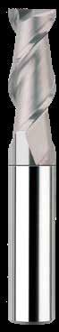
Ski-Carb 44
2 Flute Square End
FRACTIONAL SERIES
• Polished ski land with primary and secondary flute wall design minimizes chip interference by directing chips away from secondary flute
• Circular land allows for increased control at various speed and feed rates ultimately reducing chatter
• Recommended for materials ≤ 150 Bhn (≤ 7 HRc)
Contact your KYOCERA SGS Sales Engineer for more information on Corner Radius options.
= +0.0000/–0.00035
1/2–5/8 DIAMETER
3/4–1 DIAMETER
ALUMINUM ALLOYS
2024, 5052, 5086, 6061, 6073, 7075
ALUMINUM DIE CAST ALLOYS (HIGH SILICONE)
A-390,
COPPER ALLOYS
COPPER ALLOYS
Beryllium Copper C110, Manganese Bronze, Tin Bronze
PLASTICS
ABS, Polycarbonate, PVC, Polypropylene
Bhn (Brinell) HRc (Rockwell C) HRb (Rockwell B) HSM (High Speed Machining)
rpm = Vc x 3.82 / DC
ipm = Fz x 2 x rpm reduce speed and feed for materials harder than listed reduce cut depth and feed by 50% for long flute and long reach tools reduce feed and Ae when finish milling (.02 x DC maximum)
Ski-Carb 44
2 Flute Square End
• Polished ski land with primary and secondary flute wall design minimizes chip interference by directing chips away from secondary flute
• Circular land allows for increased control at various speed and feed rates ultimately reducing chatter
• Recommended for materials ≤ 150 Bhn (≤ 7 HRc)
Contact your KYOCERA SGS Sales Engineer for more information on Corner Radius options.
TOLERANCES (mm)
≤3 DIAMETER
DC = +0,000/–0,006
DCON = h 6
>3–6 DIAMETER DC = +0,000/–0,008
= h 6
>6–10 DIAMETER DC = +0,000/–0,009 DCON = h 6
>10–18 DIAMETER
DC = +0,000/–0,011
DCON = h 6
>18–20 DIAMETER
DC = +0,000/–0,013
DCON = h 6
NON-FERROUS
ALUMINUM ALLOYS
2024, 5052, 5086, 6061, 6073, 7075
ALUMINUM DIE CAST ALLOYS (HIGH SILICONE)
A-390, A-392, B- 390
COPPER ALLOYS
COPPER ALLOYS Beryllium Copper
PLASTICS
Polycarbonate, PVC, Polypropylene
Bhn (Brinell) HRc (Rockwell C) HRb (Rockwell B) HSM (High Speed Machining)
rpm = (Vc x 1000) / (DC x 3.14) mm/min = Fz x 2 x rpm reduce speed and feed for materials harder than listed reduce cut depth and feed by 50% for long flute and long reach tools reduce feed and Ae when finish milling (.02 x DC maximum)
Ski-Carb 45
2 Flute Corner Radius
FRACTIONAL SERIES
• Polished ski land with primary and secondary flute wall design minimizes chip interference by directing chips away from secondary flute
• Circular land allows for increased control at various speed and feed rates ultimately reducing chatter
• Recommended for materials ≤ 150 Bhn (≤ 7 HRc)
Contact your KYOCERA SGS Sales Engineer for reach options.
TOLERANCES (inch)
1/4–3/8 DIAMETER
1/2–5/8 DIAMETER
3/4–1 DIAMETER
= +0.0000/–0.00051
= h 6
= +0.0000/–0.0020
ALUMINUM ALLOYS
2024, 5052, 5086, 6061, 6073, 7075
ALUMINUM DIE CAST ALLOYS (HIGH SILICONE)
COPPER ALLOYS
PLASTICS ABS, Polycarbonate, PVC, Polypropylene
Bhn (Brinell) HRc (Rockwell C) HRb (Rockwell B) HSM (High Speed Machining)
rpm = Vc x 3.82 / DC
ipm = Fz x 2 x rpm
reduce speed and feed for materials harder than listed reduce cut depth and feed by 50% for long flute and long reach tools reduce feed and Ae when finish milling (.02 x DC maximum)
Ski-Carb 45
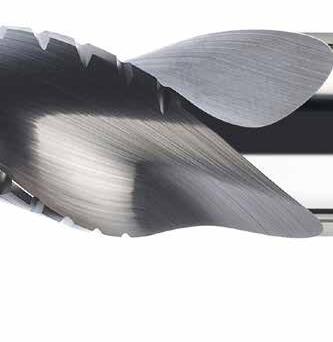
SERIES 131N
HIGH PERFORMANCE DRILLS
for Aluminum, Non-Ferrous, & Non-Metallic Applications
The Hi-PerCarb Series 131N Drill is engineered with advanced features that deliver performance beyond standard carbide and even other highperformance drills. Every element of its design targets common challenges in high-production drilling, providing reliable solutions for greater efficiency and consistency.
3-MARGIN DESIGN
• Improved hole stability over two-flute designs
• Superior surface finish, roundness and hole cylindricity
• Unsurpassed hole size control
SELF-STABILIZING POINT
• Pyramid design stabilizes the drill on contact with the workpiece
OPEN FLUTE STRUCTURE
• Efficiently transports chips while maintaining strength at high feed rates
SCULPTED GASH
• Allows chips to easily flow away from the drill center
• Reduced cutting forces over competitive three-flute designs
• Reduces frictional heat generated by excessive margin contact with the workpiece
• Parallel design maintains contact width as margin wears for performance consistency
POWERFUL PERFORMANCE, PRECISION, AND FINISH

FORCE COMPARISON
Series 131N drills with 15-20% less force than competitors
SURFACE FINISH COMPARISON
Series 131N drill results in improvement of hole finishes 30-60% over competitors
USAGE & WEAR COMPARISON
Ti-NAMITE-B coating significantly improves wear resistance, which is particularly beneficial when drilling high silicon aluminum alloys
T i -NAMITE-B COATING TECHNOLOGY
Available with TiB2 Coating (Titanium Diboride). This ceramic based coating ensures a smooth surface and a low affinity to cold welding or edge build-up, which makes it optimal for aluminum and copper applications. It has high toughness and high hardness.
• Hardness: 4000 HV
• Oxidation Temperature: 850°C / 1562°F
• Coefficient of Friction: 0.10 – 0.20
• Thickness: 1 – 2 Microns (based on tool diameter)
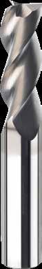
3 Flute 3xD Drill
131N 3xD
FRACTIONAL & METRIC SERIES
• 3-margin design improves hole stability and size control while providing superior finish, roundness and cylindricity
• Self-stabilizing pyramid point design stabilizes the drill on contact with the workpiece
• Open flute structure efficiently transports chips while maintaining strength at high feed rates
• Sculpted gash allows chips to easily flow away from the drill center
• Recommended for materials ≤ 175 Bhn (≤ 16 HRc)
continued on next page
TOLERANCES (inch)
≤.1181 DIAMETER
DC = +.00008/+.00047
DCON = h 6
>.1181–.2362 DIAMETER
DC = +.00016/+.00063
DCON = h 6
>.2362–.3937 DIAMETER
DC = +.00024/+.00083
DCON = h 6
>.3937–.7087 DIAMETER
DC = +.00028/+.00098
DCON = h 6
>.7087–1.1811 DIAMETER
DC = +.00031/+.00114
DCON = h 6
TOLERANCES (mm)
≤3 DIAMETER
DC = +0,002/+0,012
DCON = h 6
>3–6 DIAMETER
DC = +0,004/+0,016
DCON = h 6
>6–10 DIAMETER
DC = +0,006/+0,021
DCON = h 6
>10–18 DIAMETER
DC = +0,007/+0,025
DCON = h 6
NON-FERROUS
131N 3xD
FRACTIONAL & METRIC SERIES
• 3-margin design improves hole stability and size control while providing superior finish, roundness and cylindricity
• Self-stabilizing pyramid point design stabilizes the drill on contact with the workpiece
• Open flute structure efficiently transports chips while maintaining strength at high feed rates
• Sculpted gash allows chips to easily flow away from the drill center
• Recommended for materials ≤ 175 Bhn (≤ 16 HRc)
continued on next page
3 Flute 3xD Drill
131N 3xD
FRACTIONAL & METRIC SERIES
• 3-margin design improves hole stability and size control while providing superior finish, roundness and cylindricity
• Self-stabilizing pyramid point design stabilizes the drill on contact with the workpiece
• Open flute structure efficiently transports chips while maintaining strength at high feed rates
• Sculpted gash allows chips to easily flow away from the drill center
• Recommended for materials ≤ 175 Bhn (≤ 16 HRc)
TOLERANCES (inch)
≤.1181 DIAMETER
DC = +.00008/+.00047
DCON = h 6
>.1181–.2362 DIAMETER
DC = +.00016/+.00063
DCON = h 6
>.2362–.3937 DIAMETER
DC = +.00024/+.00083
DCON = h 6
>.3937–.7087 DIAMETER
DC = +.00028/+.00098
DCON = h 6
>.7087–1.1811 DIAMETER
DC = +.00031/+.00114
DCON = h 6
TOLERANCES (mm)
≤3 DIAMETER
DC = +0,002/+0,012
DCON = h 6
>3–6 DIAMETER
DC = +0,004/+0,016
DCON = h 6
>6–10 DIAMETER
DC = +0,006/+0,021
DCON = h 6
>10–18 DIAMETER
DC = +0,007/+0,025
DCON = h 6
NON-FERROUS
Flute 3xD Drill
TOLERANCES (inch)
≤.1181 DIAMETER
DC = +.00008/+.00047
DCON = h 6
>.1181–.2362 DIAMETER
DC = +.00016/+.00063
DCON = h 6
>.2362–.3937 DIAMETER
DC = +.00024/+.00083
DCON = h 6
>.3937–.7087 DIAMETER
DC = +.00028/+.00098
DCON = h 6
>.7087–1.1811 DIAMETER
DC = +.00031/+.00114
DCON = h 6
TOLERANCES (mm)
≤3 DIAMETER
DC = +0,002/+0,012
DCON = h 6
>3–6 DIAMETER
DC = +0,004/+0,016
DCON = h 6
>6–10 DIAMETER
DC = +0,006/+0,021
DCON = h 6
>10–18 DIAMETER
DC = +0,007/+0,025
DCON = h 6
NON-FERROUS
0.7500
131N 3xD
FRACTIONAL & METRIC SERIES
• 3-margin design improves hole stability and size control while providing superior finish, roundness and cylindricity
• Self-stabilizing pyramid point design stabilizes the drill on contact with the workpiece
• Open flute structure efficiently transports chips while maintaining strength at high feed rates
• Sculpted gash allows chips to easily flow away from the drill center
• Recommended for materials ≤ 175 Bhn (≤ 16 HRc)
3 Flute 3xD Drill
3 Flute 5xD Drill
131N 5xD
FRACTIONAL & METRIC SERIES
• 3-margin design improves hole stability and size control while providing superior finish, roundness and cylindricity
• Self-stabilizing pyramid point design stabilizes the drill on contact with the workpiece
• Open flute structure efficiently transports chips while maintaining strength at high feed rates
• Sculpted gash allows chips to easily flow away from the drill center
• Recommended for materials ≤ 175 Bhn (≤ 16 HRc)
continued on next page
TOLERANCES (inch)
≤.1181 DIAMETER
DC = +.00008/+.00047
DCON = h 6
>.1181–.2362 DIAMETER
DC = +.00016/+.00063
DCON = h 6
>.2362–.3937 DIAMETER
DC = +.00024/+.00083
DCON = h 6
>.3937–.7087 DIAMETER
DC = +.00028/+.00098
DCON = h 6
>.7087–1.1811 DIAMETER
DC = +.00031/+.00114
DCON = h 6
TOLERANCES (mm)
≤3 DIAMETER
DC = +0,002/+0,012
DCON = h 6
>3–6 DIAMETER
DC = +0,004/+0,016
DCON = h 6
>6–10 DIAMETER
DC = +0,006/+0,021
DCON = h 6
>10–18 DIAMETER
DC = +0,007/+0,025
DCON = h 6
64854 continued on next page
5xD
• 3-margin design improves hole stability and size control while providing superior finish, roundness and cylindricity
• Self-stabilizing pyramid point design stabilizes the drill on contact with the workpiece
• Open flute structure efficiently transports chips while maintaining strength at high feed rates
• Sculpted gash allows chips to easily flow away from the drill center
• Recommended for materials ≤ 175 Bhn (≤ 16 HRc)
3 Flute 5xD Drill
131N 5xD
FRACTIONAL & METRIC SERIES
• 3-margin design improves hole stability and size control while providing superior finish, roundness and cylindricity
• Self-stabilizing pyramid point design stabilizes the drill on contact with the workpiece
• Open flute structure efficiently transports chips while maintaining strength at high feed rates
• Sculpted gash allows chips to easily flow away from the drill center
• Recommended for materials ≤ 175 Bhn (≤ 16 HRc)
0.4375
continued on next page
TOLERANCES (inch)
≤.1181 DIAMETER
DC = +.00008/+.00047
DCON = h 6
>.1181–.2362 DIAMETER
DC = +.00016/+.00063
DCON = h 6
>.2362–.3937 DIAMETER
DC = +.00024/+.00083
DCON = h 6
>.3937–.7087 DIAMETER
DC = +.00028/+.00098
DCON = h 6
>.7087–1.1811 DIAMETER
DC = +.00031/+.00114
DCON = h 6
TOLERANCES (mm)
≤3 DIAMETER
DC = +0,002/+0,012
DCON = h 6
>3–6 DIAMETER
DC = +0,004/+0,016
DCON = h 6
>6–10 DIAMETER
DC = +0,006/+0,021
DCON = h 6
>10–18 DIAMETER
DC = +0,007/+0,025
DCON = h 6
TOLERANCES (inch)
≤.1181 DIAMETER
DC = +.00008/+.00047
DCON = h 6
>.1181–.2362 DIAMETER
DC = +.00016/+.00063
DCON = h 6
>.2362–.3937 DIAMETER
DC = +.00024/+.00083
DCON = h 6
>.3937–.7087 DIAMETER
DC = +.00028/+.00098
DCON = h 6
>.7087–1.1811 DIAMETER
DC = +.00031/+.00114
DCON = h 6
TOLERANCES (mm)
≤3 DIAMETER
DC = +0,002/+0,012
DCON = h 6
>3–6 DIAMETER
DC = +0,004/+0,016
DCON = h 6
>6–10 DIAMETER
DC = +0,006/+0,021
DCON = h 6
>10–18 DIAMETER
DC = +0,007/+0,025
DCON = h 6
0.6299
0.7500 19,050 mm 3/4 20,0
5xD
• 3-margin design improves hole stability and size control while providing superior finish, roundness and cylindricity
• Self-stabilizing pyramid point design stabilizes the drill on contact with the workpiece
• Open flute structure efficiently transports chips while maintaining strength at high feed rates
• Sculpted gash allows chips to easily flow away from the drill center
• Recommended for materials ≤ 175 Bhn (≤ 16 HRc)
3 Flute 5xD Drill
& 5D
ALUMINUM ALLOYS > 12% SI A356.0, 390.0, 319.0
COPPER ALLOYS
Alum Bronze, Muntz Brass, Navel Brass
PVC, Polypropylene
175 Bhn or
Bhn (Brinell) HRc (Rockwell C) HRb (Rockwell B)
rpm = Vc x 3.82 / DC
ipm = Fr x rpm reduce speed and feed for materials harder than listed
METRIC
131N Recommended Cutting Conditions
Refer to the SGS APEX: Application Expert for complete technical information www.kyocera-sgstool.com/apex
Bhn (Brinell) HRc (Rockwell C) HRb (Rockwell B)
rpm = (Vc x 1000) / (DC x 3.14) mm/min = Fr x rpm
reduce speed and feed for materials harder than listed
Refer to the SGS APEX: Application Expert for complete technical information www.kyocera-sgstool.com/apex
APPLICA TION EXPER T
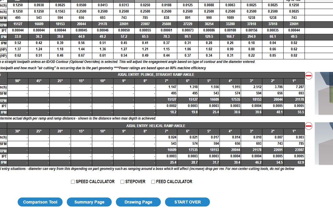
Say hello to APEX: Application Expert KYOCERA SGS's enhanced web application designed to make your SGS tool selection and parameter setup faster and more effective!
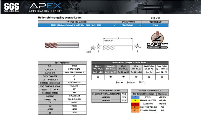


OPTIMIZE TOOL PERFORMANCE
Gain essential application data to optimize tool performance, including cutting parameters and material recommendations.
SAVE TIME
Easily select application types, units, and materials with our user-friendly interface and autofill features.
COMPARE AND CUSTOMIZE
Use powerful tools to tailor results, compare up to five options, and visualize ramping parameters with detailed drawings.
EXPORT AND SHARE
Generate PDFs with application data, add comments, and print precise line drawings with detailed specifications.
Visit: www.kyocera-sgstool.com/apex
or Click the APEX Logo on any Product Detail Page.